Embed Size (px)
Citation preview

Copyright 2004
IMPORTANT!
THIS DOCUMENT CONTAINS IMPORTANT SAFETY INSTRUCTIONS-
PLEASE SAVE THESE INSTRUCTIONS!
Symmetra MW Parallel System
with Ext. Bypass SSW 400V
Paral lel Instal lat ion Guide


Contents
Safety .....................................................................1
IMPORTANT SAFETY INSTRUCTIONS - SAVE THESE INSTRUCTIONS . . . . . . . . . . . . . . . . . . . . . . . . . . 1
Symbols used in this guide . . . . . . . . . . . . . . . . . . . . . . . . . . . . 1
Parallel Operation Principle .....................................3
Introduction . . . . . . . . . . . . . . . . . . . . . . . . . . . . . . . . . . . . . . . 3Single mains systems . . . . . . . . . . . . . . . . . . . . . . . . . . . . . . . . . 3
Dual mains systems . . . . . . . . . . . . . . . . . . . . . . . . . . . . . . . . . . 4
Specifications for Parallel Systems ............................5
400 kW . . . . . . . . . . . . . . . . . . . . . . . . . . . . . . . . . . . . . . . . . . 5Required breaker settings . . . . . . . . . . . . . . . . . . . . . . . . . . . . . 5
600 kW . . . . . . . . . . . . . . . . . . . . . . . . . . . . . . . . . . . . . . . . . . 7Required breaker settings . . . . . . . . . . . . . . . . . . . . . . . . . . . . . 7
800 kW . . . . . . . . . . . . . . . . . . . . . . . . . . . . . . . . . . . . . . . . . . 9Breaker settings . . . . . . . . . . . . . . . . . . . . . . . . . . . . . . . . . . . . 9
1000 kW . . . . . . . . . . . . . . . . . . . . . . . . . . . . . . . . . . . . . . . . 11Breaker settings . . . . . . . . . . . . . . . . . . . . . . . . . . . . . . . . . . . 11
1200 kW . . . . . . . . . . . . . . . . . . . . . . . . . . . . . . . . . . . . . . . . 13Breaker settings . . . . . . . . . . . . . . . . . . . . . . . . . . . . . . . . . . . 13
1400 kW . . . . . . . . . . . . . . . . . . . . . . . . . . . . . . . . . . . . . . . . 15Breaker settings . . . . . . . . . . . . . . . . . . . . . . . . . . . . . . . . . . . 15
1600 kW . . . . . . . . . . . . . . . . . . . . . . . . . . . . . . . . . . . . . . . . 17Breaker settings . . . . . . . . . . . . . . . . . . . . . . . . . . . . . . . . . . . 17
Electrical Installation .............................................19
Interconnecting Parallel Units . . . . . . . . . . . . . . . . . . . . . . . . . 19
Symmetra MW Parallel System with External Bypass SSW 400 V - 990-2274 i

Power Wiring Principle . . . . . . . . . . . . . . . . . . . . . . . . . . . . . . 20
Communication Cables ......................................... 21
Communication Cables between UPS System and Ancillary Equipment . . . . . . . . . . . . . . . . . . . . . . . . . . . . . . . . 21
Overview of communication cables in parallel systems . . . . . . . 21
UPS 1 Communication Cables . . . . . . . . . . . . . . . . . . . . . . . . . 22Communication cables between UPS 1 and Battery CAN I/O Board ID 0 in Battery Breaker Box 1 . . . . . . . . 22
Communication cables between Battery CAN I/O Board ID 0 and Battery CAN I/O Board ID 1 in Battery Breaker Box 1(if available) . . . . . . . . . . . . . . . . . . . . . . . . . . . . . . . . . . . . . . 24
Communication cables between UPS 1 and External EPO . . . . . 25
Communication cables between UPS 1 and MBP CAN I/O Board UPS 1 in Maintenance Bypass Panel (MBP) . . . . . . . . . . . 26
UPS 2 Communication Cables 28Communication cables between UPS 2 and Battery CAN I/O Board ID 0 in Battery Breaker Box 2 . . . . . . . . . . . . . . . . . . . . 28
Communication cables between Battery CAN I/O Board ID 0 and Battery CAN I/O Board ID 1 in Battery Breaker Box 2 (if available) . . . . . . . . . . . . . . . . . . . . . . . . . . . . . . . . . . . . . . 30
Communication cables between UPS 2 and External EPO . . . . . 31
Communication cables between UPS 2 and MBP CAN I/O Board UPS 2 in Maintenance Bypass Panel (MBP) . . . . . . . . . . . 32
UPS 3 Communication Cables . . . . . . . . . . . . . . . . . . . . . . . . . 34Communication cables between UPS 3 and Battery CAN I/O Board ID 0 in Battery Breaker Box 3 . . . . . . . . . . . . . . . . . . . . 34
Communication cables between Battery CAN I/O Board ID 0 and Battery CAN I/O Board ID 1 in Battery Breaker Box 3 (if available) . . . . . . . . . . . . . . . . . . . . . . . . . . . . . . . . . . . . . . 36
Communication cables between UPS 3 and External EPO . . . . . 37
Communication cables between UPS 3 and MBP CAN I/O Board UPS 3 in Maintenance Bypass Panel (MBP) . . . . . . . . . . . 38
External Bypass Static Switch Communication Cables . . . . . . . 40Communication cables between External Bypass SSW and MBP CAN I/O Board Bypass SSW . . . . . . . . . . . . . . . . . . . . . . . 40
Communication cables between External Bypass SSW and External EPO . . . . . . . . . . . . . . . . . . . . . . . . . . . . . . . . . . . . . . 41
Technical Support ................................................. 43
ii Symmetra MW Parallel System with External Bypass SSW 400 V - 990-2274

Safety
IMPORTANT SAFETY INSTRUCTIONS - SAVE THESE INSTRUCTIONS
This guide contains important instructions for the UPS and the External Bypass Static Switch that should be followed when handling the UPS and the External Bypass Static Switch.
Symbols used in this guide
WARNING!Risk of Electric Shock.
CAUTION!Read this important information to avoid equipment damage.
Note
Indicates important information.
Indicates that more information is available on this subject in a different section of this manual.
See also
Indicates that more information is available on the same subject in a different manual.
Symmetra MW Parallel System with External Bypass SSW 400 V - 990-2274 1

Parallel Operation Principle
Introduction
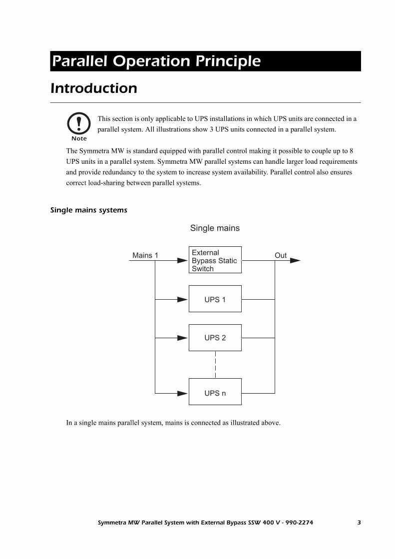
The Symmetra MW is standard equipped with parallel control making it possible to couple up to 8 UPS units in a parallel system. Symmetra MW parallel systems can handle larger load requirements and provide redundancy to the system to increase system availability. Parallel control also ensures correct load-sharing between parallel systems.
Single mains systems
In a single mains parallel system, mains is connected as illustrated above.
Note
This section is only applicable to UPS installations in which UPS units are connected in a parallel system. All illustrations show 3 UPS units connected in a parallel system.
External Bypass Static Switch
Mains 1 Out
Single mains
UPS 1
UPS 2
UPS n
Symmetra MW Parallel System with External Bypass SSW 400 V - 990-2274 3

Parallel Operation Principle: Introduction
Dual mains systems
In a dual mains parallel system, mains 2 is connected to the External Bypass Static Switch and mains 1 is connected to the UPS units as illustrated above.
External Bypass Static Switch
Mains 2
Mains 1
Out
Dual mains
UPS 1
UPS 2
UPS n
4 Symmetra MW Parallel System with External Bypass SSW 400 V - 990-2274

Specifications for Parallel Systems
400 kW
Required breaker settings
The required breaker settings in the table below is applicable to parallel systems including up to three UPS units and an External Bypass Static Switch.
Q1 and Q5 settings in parallel systems.
Q2 settings in parallel systems.
Q1 and Q5 applicable to UPS 1, UPS 2 and UPS 3
Duration [S] Current [A] Total load [%] Event/Operation
< 0.005 18 kA -- Internal fault clearing
600 750* 130 Overload on-line
598 100 On-line
* Only applicable to Q1
Note
Q1 and Q5 breaker settings are the same for all UPS units regardless of the number of UPS units in the parallel system.
Q2 applicable to UPS 1, UPS 2 and UPS 3
Duration [S] Current [A] Total load [%] Event/Operation
< 0.005 18 kA -- Internal fault clearing
60 1155 200 Overload on-line
600 721 125 Overload on-line
577 100 On-line
Note
Q2 breaker settings are the same for all UPS units regardless of the number of UPS units in the parallel system.
∞
∞
Symmetra MW Parallel System with External Bypass SSW 400 V - 990-2274 5

Specifications for Parallel Systems: 400 kW
Q4 settings in parallel systems.
18 kA is the maximum peak let-through current (including safety factor) available during clearing of an internal fault in a 200 kW section or a Power Module. During or after a controlled fault clearing, no breakers are allowed to trip on the instantaneous trip setting below the specified value. The maximum peak let through current is applicable to utility with prospective short-circuit currents up to 200 kA.
Q4 settings in parallel systems with 2 UPS units
Duration [S] Current [A] Total load [%] Event/Operation
< 0.005 18 kA -- Internal fault clearing
60 2310 200 Overload on-line
600 1444 125 Overload on-line
1155 100 On-line
Q4 settings in parallel systems with 3 UPS units
Duration [S] Current [A] Total load [%] Event/Operation
< 0.005 18 kA -- Internal fault clearing
60 3464 200 Overload on-line
600 2165 125 Overload on-line
1732 100 On-line
Note
The instantaneous trip setting must not be derated even though the UPS system is derated in system output power. The system size has no influence on the instantaneous trip setting.
Note
For derated systems, the APC Application Team provides correct breaker settings and breaker frame sizes.
Note
For upstream breakers not mentioned in the table, the APC Application Team provides the correct settings for on-line, overload, and trip currents breaker settings.
∞
∞
6 Symmetra MW Parallel System with External Bypass SSW 400 V - 990-2274

600 kW
Required breaker settings
The required breaker settings in the table below is applicable to parallel systems including up to three UPS units and an External Bypass Static Switch.
Q1 and Q5 settings in parallel systems.
Q2 settings in parallel systems.
Q1 and Q5 applicable to UPS 1, UPS 2 and UPS 3
Duration [S] Current [A] Total load [%] Event/Operation
< 0.005 18 kA -- Internal fault clearing
600 1126* 130 Overload on-line
896 100 On-line
* Only applicable to Q1
Note
Q1 and Q5 breaker settings are the same for all UPS units regardless of the number of UPS units in the parallel system.
Q2 applicable to UPS 1, UPS 2 and UPS 3
Duration [S] Current [A] Total load [%] Event/Operation
< 0.005 18 kA -- Internal fault clearing
60 1732 200 Overload on-line
600 1083 125 Overload on-line
866 100 On-line
Note
Q2 breaker settings are the same for all UPS units regardless of the number of UPS units in the parallel system.
∞
∞
Symmetra MW Parallel System with External Bypass SSW 400 V - 990-2274 7

Specifications for Parallel Systems: 600 kW
Q4 settings in parallel systems.
18 kA is the maximum peak let-through current (including safety factor) available during clearing of an internal fault in a 200 kW section or a Power Module. During or after a controlled fault clearing, no breakers are allowed to trip on the instantaneous trip setting below the specified value. The maximum peak let through current is applicable to utility with prospective short-circuit currents up to 200 kA.
Q4 settings in parallel systems with 2 UPS units
Duration [S] Current [A] Total load [%] Event/Operation
< 0.005 18 kA -- Internal fault clearing
60 3464 200 Overload on-line
600 2165 125 Overload on-line
1732 100 On-line
Q4 settings in parallel systems with 3 UPS units
Duration [S] Current [A] Total load [%] Event/Operation
< 0.005 18 kA -- Internal fault clearing
60 5196 200 Overload on-line
600 3248 125 Overload on-line
2598 100 On-line
Note
The instantaneous trip setting must not be derated even though the UPS system is derated in system output power. The system size has no influence on the instantaneous trip setting.
Note
For derated systems, the APC Application Team provides correct breaker settings and breaker frame sizes.
Note
For upstream breakers not mentioned in the table, the APC Application Team provides the correct settings for on-line, overload, and trip currents breaker settings.
∞
∞
8 Symmetra MW Parallel System with External Bypass SSW 400 V - 990-2274

800 kW
Breaker settings
The required breaker settings in the table below are applicable to parallel systems including up to three UPS units and an External Bypass Static Switch.
Q1 settings.
Q2 settings.
Q1 applicable to UPS 1, UPS 2 and UPS 3
Duration [S] Current [A] Total load [%] Event/Operation
< 0.005 18 kA -- Internal fault clearing
600 1502 130 Overload on-line
1195 100 On-line
Note
Q1 breaker settings are the same for all UPS units regardless of the number of UPS units in the parallel system.
Q2 applicable to UPS 1, UPS 2 and UPS 3
Duration [S] Current [A] Total load [%] Event/Operation
< 0.005 18 kA -- Internal fault clearing. Will end as upstream
60 2310 200 Overload on-line
600 1444 125 Overload on-line
1155 100 On-line
∞
∞
Symmetra MW Parallel System with External Bypass SSW 400 V - 990-2274 9

Specifications for Parallel Systems: 800 kW
Q4, Q5 and Q6 settings.
18 kA is the maximum peak let-through current (including safety factor) available during clearing of an internal fault in a 200 kW section or a Power Module. During or after a controlled fault clearing, no breakers are allowed to trip on the instantaneous trip setting below the specified value. The maximum peak let through current is applicable to utility with prospective short-circuit currents up to 200 kA.
Q4, Q5, and Q6 settings in parallel system with 2 UPS units
Duration [S] Current [A] Total load [%] Event/Operation
< 0.005 18 kA -- Internal fault clearing. Will end as upstream
60 4620* 200 Overload on-line
600 2888* 125 Overload on-line
2310 100 On-line
* Only applicable to Q4
Q4, Q5, and Q6 settings in parallel system with 3 UPS units
Duration [S] Current [A] Total load [%] Event/Operation
< 0.005 18 kA -- Internal fault clearing. Will end as upstream
60 6930* 200 Overload on-line
600 4331* 125 Overload on-line
3465 100 On-line
* Only applicable to Q4
Note
The instantaneous trip setting must not be derated even though the UPS system is derated in system output power. The system size has no influence on the instantaneous trip setting.
Note
For derated systems, the APC Application Team provides correct breaker settings and breaker frame sizes.
Note
For upstream breakers not mentioned in the table, the APC Application Team provides the correct settings for on-line, overload, and trip currents breaker settings.
∞
∞
10 Symmetra MW Parallel System with External Bypass SSW 400 V - 990-2274

1000 kW
Breaker settings
The required breaker settings in the table below are applicable to parallel systems including up to three UPS units and an External Bypass Static Switch.
Q1 settings.
Q2 settings.
Q1 applicable to UPS 1, UPS 2 and UPS 3
Duration [S] Current [A] Total load [%] Event/Operation
< 0.005 18 kA -- Internal fault clearing
600 1833 127 Overload on-line
1494 100 On-line
Note
Q1 breaker settings are the same for all UPS units regardless of the number of UPS units in the parallel system.
Q2 applicable to UPS 1, UPS 2 and UPS 3
Duration [S] Current [A] Total load [%] Event/Operation
< 0.005 18 kA -- Internal fault clearing. Will end as upstream
60 2886 200 Overload on-line
600 1804 125 Overload on-line
1443 100 On-line
∞
∞
Symmetra MW Parallel System with External Bypass SSW 400 V - 990-2274 11
Specifications for Parallel Systems: 1000 kW
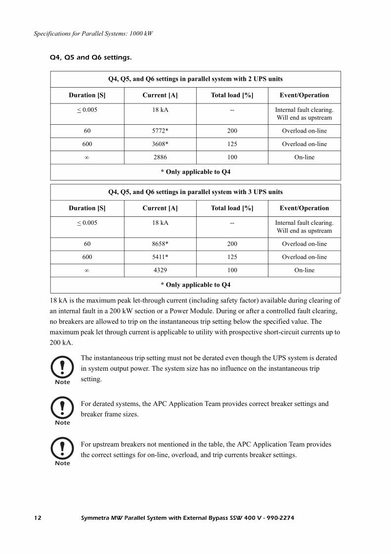
Q4, Q5 and Q6 settings.
18 kA is the maximum peak let-through current (including safety factor) available during clearing of an internal fault in a 200 kW section or a Power Module. During or after a controlled fault clearing, no breakers are allowed to trip on the instantaneous trip setting below the specified value. The maximum peak let through current is applicable to utility with prospective short-circuit currents up to 200 kA.
Q4, Q5, and Q6 settings in parallel system with 2 UPS units
Duration [S] Current [A] Total load [%] Event/Operation
< 0.005 18 kA -- Internal fault clearing. Will end as upstream
60 5772* 200 Overload on-line
600 3608* 125 Overload on-line
2886 100 On-line
* Only applicable to Q4
Q4, Q5, and Q6 settings in parallel system with 3 UPS units
Duration [S] Current [A] Total load [%] Event/Operation
< 0.005 18 kA -- Internal fault clearing. Will end as upstream
60 8658* 200 Overload on-line
600 5411* 125 Overload on-line
4329 100 On-line
* Only applicable to Q4
Note
The instantaneous trip setting must not be derated even though the UPS system is derated in system output power. The system size has no influence on the instantaneous trip setting.
Note
For derated systems, the APC Application Team provides correct breaker settings and breaker frame sizes.
Note
For upstream breakers not mentioned in the table, the APC Application Team provides the correct settings for on-line, overload, and trip currents breaker settings.
∞
∞
12 Symmetra MW Parallel System with External Bypass SSW 400 V - 990-2274

1200 kW
Breaker settings
The required breaker settings in the table below are applicable to parallel systems including up to three UPS units and an External Bypass Static Switch.
Q1 settings.
Q2 settings.
Q1 applicable to UPS 1, UPS 2 and UPS 3
Duration [S] Current [A] Total load [%] Event/Operation
< 0.005 18 kA -- Internal fault clearing
600 2252 130 Overload on-line
1793 100 On-line
Note
Q1 breaker settings are the same for all UPS units regardless of the number of UPS units in the parallel system.
Q2 applicable to UPS 1, UPS 2 and UPS 3
Duration [S] Current [A] Total load [%] Event/Operation
< 0.005 18 kA -- Internal fault clearing. Will end as upstream
60 3464 200 Overload on-line
600 2165 125 Overload on-line
1732 100 On-line
∞
∞
Symmetra MW Parallel System with External Bypass SSW 400 V - 990-2274 13

Specifications for Parallel Systems: 1200 kW
Q4, Q5 and Q6 settings.
18 kA is the maximum peak let-through current (including safety factor) available during clearing of an internal fault in a 200 kW section or a Power Module. During or after a controlled fault clearing, no breakers are allowed to trip on the instantaneous trip setting below the specified value. The maximum peak let through current is applicable to utility with prospective short-circuit currents up to 200 kA.
Q4, Q5, and Q6 settings in parallel system with 2 UPS units
Duration [S] Current [A] Total load [%] Event/Operation
< 0.005 18 kA -- Internal fault clearing. Will end as upstream
60 6928* 200 Overload on-line
600 4330* 125 Overload on-line
3464 100 On-line
* Only applicable to Q4
Q4, Q5, and Q6 settings in parallel system with 3 UPS units
Duration [S] Current [A] Total load [%] Event/Operation
< 0.005 18 kA -- Internal fault clearing. Will end as upstream
60 10390* 200 Overload on-line
600 6495* 125 Overload on-line
5196 100 On-line
* Only applicable to Q4
Note
The instantaneous trip setting must not be derated even though the UPS system is derated in system output power. The system size has no influence on the instantaneous trip setting.
Note
For derated systems, the APC Application Team provides correct breaker settings and breaker frame sizes.
Note
For upstream breakers not mentioned in the table, the APC Application Team provides the correct settings for on-line, overload, and trip currents breaker settings.
∞
∞
14 Symmetra MW Parallel System with External Bypass SSW 400 V - 990-2274

1400 kW
Breaker settings
The required breaker settings in the table below are applicable to parallel systems including up to three UPS units and an External Bypass Static Switch.
Q1 settings.
Q2 settings.
Q1 applicable to UPS 1, UPS 2 and UPS 3
Duration [S] Current [A] Total load [%] Event/Operation
< 0.005 18 kA -- Internal fault clearing
600 2627 130 Overload on-line
2091 100 On-line
Note
Q1 breaker settings are the same for all UPS units regardless of the number of UPS units in the parallel system.
Q2 applicable to UPS 1, UPS 2 and UPS 3
Duration [S] Current [A] Total load [%] Event/Operation
< 0.005 18 kA -- Internal fault clearing. Will end as upstream
60 4042 200 Overload on-line
600 2526 125 Overload on-line
2021 100 On-line
∞
∞
Symmetra MW Parallel System with External Bypass SSW 400 V - 990-2274 15

Specifications for Parallel Systems: 1400 kW
Q4, Q5 and Q6 settings.
18 kA is the maximum peak let-through current (including safety factor) available during clearing of an internal fault in a 200 kW section or a Power Module. During or after a controlled fault clearing, no breakers are allowed to trip on the instantaneous trip setting below the specified value. The maximum peak let through current is applicable to utility with prospective short-circuit currents up to 200 kA.
Q4, Q5, and Q6 settings in parallel system with 2 UPS units
Duration [S] Current [A] Total load [%] Event/Operation
< 0.005 18 kA -- Internal fault clearing. Will end as upstream
60 8084* 200 Overload on-line
600 5053* 125 Overload on-line
4042 100 On-line
* Only applicable to Q4
Q4, Q5, and Q6 settings in parallel system with 3 UPS units
Duration [S] Current [A] Total load [%] Event/Operation
< 0.005 18 kA -- Internal fault clearing. Will end as upstream
60 12130* 200 Overload on-line
600 7579* 125 Overload on-line
6063 100 On-line
* Only applicable to Q4
Note
The instantaneous trip setting must not be derated even though the UPS system is derated in system output power. The system size has no influence on the instantaneous trip setting.
Note
For derated systems, the APC Application Team provides correct breaker settings and breaker frame sizes.
Note
For upstream breakers not mentioned in the table, the APC Application Team provides the correct settings for on-line, overload, and trip currents breaker settings.
∞
∞
16 Symmetra MW Parallel System with External Bypass SSW 400 V - 990-2274

1600 kW
Breaker settings
The required breaker settings in the table below are applicable to parallel systems including up to three UPS units and an External Bypass Static Switch.
Q1 settings.
Q2 settings.
Q1 applicable to UPS 1, UPS 2 and UPS 3
Duration [S] Current [A] Total load [%] Event/Operation
< 0.005 18 kA -- Internal fault clearing
600 3002 130 Overload on-line
2390 100 On-line
Note
Q1 breaker settings are the same for all UPS units regardless of the number of UPS units in the parallel system.
Q2 applicable to UPS 1, UPS 2 and UPS 3
Duration [S] Current [A] Total load [%] Event/Operation
< 0.005 18 kA -- Internal fault clearing. Will end as upstream
60 4618 200 Overload on-line
600 2886 125 Overload on-line
2309 100 On-line
∞
∞
Symmetra MW Parallel System with External Bypass SSW 400 V - 990-2274 17

Specifications for Parallel Systems: 1600 kW
Q4, Q5 and Q6 settings.
18 kA is the maximum peak let-through current (including safety factor) available during clearing of an internal fault in a 200 kW section or a Power Module. During or after a controlled fault clearing, no breakers are allowed to trip on the instantaneous trip setting below the specified value. The maximum peak let through current is applicable to utility with prospective short-circuit currents up to 200 kA.
Q4, Q5, and Q6 settings in parallel system with 2 UPS units
Duration [S] Current [A] Total load [%] Event/Operation
< 0.005 18 kA -- Internal fault clearing. Will end as upstream
60 9236* 200 Overload on-line
600 5773* 125 Overload on-line
4618 100 On-line
* Only applicable to Q4
Q4, Q5, and Q6 settings in parallel system with 3 UPS units
Duration [S] Current [A] Total load [%] Event/Operation
< 0.005 18 kA -- Internal fault clearing. Will end as upstream
60 13850* 200 Overload on-line
600 8659* 125 Overload on-line
6927 100 On-line
* Only applicable to Q4
Note
The instantaneous trip setting must not be derated even though the UPS system is derated in system output power. The system size has no influence on the instantaneous trip setting.
Note
For derated systems, the APC Application Team provides correct breaker settings and breaker frame sizes.
Note
For upstream breakers not mentioned in the table, the APC Application Team provides the correct settings for on-line, overload, and trip currents breaker settings.
∞
∞
18 Symmetra MW Parallel System with External Bypass SSW 400 V - 990-2274

Electrical Installation
Interconnecting Parallel Units
Interconnect the UPS units in a parallel system using the provided P-Bus cables:
Connect X126A from the External Bypass Static Switch to X126B in UPS 1 Control Section.
Connect X127A from the External Bypass Static Switch to X127B in UPS 1 Control Section Section.
Connect X126A from UPS 1 Control Section to X126B in UPS 2 Control Section.
Connect X127A from UPS 1 Control Section to X127B in UPS 2 Control Section.
Connect X126A from UPS 2 Control Section to X126B in UPS 3 Control Section.
Connect X127A from UPS 2 Control Section to X127B in UPS 3 Control Section.
In the External Bypass Static Switch, connect terminators 0M-1879A to X126B and X127B.
In UPS 3, connect terminators 0M-1880A to X126A and X127A.
X012 X013
X103X104
Backfeed protectionEpo OutEpo Out
X131 X132
Ext. Epo Sup Epo Switch
X185 X177 X128 X129
X133A CAN IO Battery
X134A CAN IO MBP
X135
K1
V1
Display
Par
alle
l bu
s 2
X12
7B
X12
7A
X126B
X126A
Parallel b
us 1
X126B
X126A
X126B
X126A
Int. Ext.
CONNECTION PLANE ASSY NO: 640-4607A_Rev.02
X012 X013
X103X104
Backfeed protectionEpo OutEpo Out
X131 X132
Ext. Epo Sup Epo Switch
X185 X177 X128 X129
X133A CAN IO Battery
X134A CAN IO MBP
X135
K1
V1
Display
Par
alle
l bu
s 2
X12
7B
X12
7A
X126B
X126A
Parallel b
us 1
X126B
X126A
X126B
X126A
Int. Ext.
CONNECTION PLANE ASSY NO: 640-4607A_Rev.02 2004 APC 2004 APC 2004 APC
2004 APC
X126B X126A X127A X127BX126B X126A X127A X127BX126B X126A X127A X127B
X126B X126AX127BX127A
External Bypass SSW
UPS 1 UPS 2 UPS 3
Symmetra MW Parallel System with External Bypass SSW 400 V - 990-2274 19

Power Wiring PrincipleM
aint
enan
ce B
ypas
s P
anel
(M
BP
)S
ymm
etra
MW
- a
Sym
met
ra M
W -
b
Ext
erna
l Byp
ass
Sta
tic S
witc
h
Bat
tery
Bre
aker
B
ox 1
a
Bat
tery
Bre
aker
B
ox 2
a
Bat
tery
Bre
aker
B
ox 1
b
Bat
tery
Bre
aker
B
ox 2
b
Bat
terie
s 1a
Bat
terie
s 2a
Bat
terie
s
Bat
terie
s 2b
MA
INS
1. 2. 3. 4. 5. 6. 7. 8. 9. 10.
11.
12.
13.
14.M
AIN
S S
OU
RC
E 3
X4
00
/23
0V
TN
-S (
PR
OV
IDE
D B
Y O
TH
ER
S).
Q1
-
Q6
WIT
H 2
NO
/2N
C A
UX
ILIA
RY
CO
NT
AC
TS
.
Q7
, Q
8 D
C R
AT
ED
TH
ER
MA
L M
AG
NE
TIC
TR
IP M
OL
DE
D C
AS
E C
IRC
UIT
BR
EA
KE
R.
WIT
H 2
4V
OL
T D
C U
ND
ER
VO
LT
AG
E R
EL
EA
SE
(U
VR
) A
ND
2N
O/2
NC
AU
XIL
IAR
Y C
ON
TA
CT
S.
AL
L A
C P
OW
ER
CA
BL
ING
IS
L1
,L2
,L3
,N,P
E.
UP
S I
NP
UT
AN
D O
UT
PU
T C
ON
DU
CT
OR
S M
US
T B
E I
N S
EP
AR
AT
E C
AB
LE
RU
NS
.
UP
S A
ND
ST
AT
IC B
YP
AS
S W
ITH
ST
AN
D R
AT
ING
, Ic
w =
20
0 K
A
SE
E T
HE
IN
ST
AL
LA
TIO
N G
UID
E F
OR
TH
E B
RE
AK
ER
SE
TT
ING
S O
F Q
1,
Q3
, Q
4 A
ND
Q5
.
DC
CA
BL
ING
SH
OU
LD
BE
SE
GR
EG
AT
ED
FR
OM
AC
CA
BL
ING
SE
E B
AT
TE
RY
IN
ST
AL
LA
TIO
N I
NF
OR
MA
TIO
N
PO
WE
R W
IRIN
G A
ND
CO
NT
RO
L W
IRIN
G M
US
T B
E S
EG
RE
GA
TE
D.
AC
CIR
CU
IT C
AB
LE
LE
NG
TH
S (
INP
UT
AN
D O
UT
PU
T)
SH
OU
LD
BE
EQ
UA
L O
N A
LL
MO
DU
LE
S
DC
CIR
CU
IT C
AB
LE
LE
NG
TH
S S
HO
UL
D B
E E
QU
AL
ON
AL
L M
OD
UL
ES
= C
AB
LIN
G P
RO
VID
ED
BY
OT
HE
RS
INS
TA
LL
AT
ION
MU
ST
CO
MP
LY
WIT
H N
AT
ION
AL
AN
D L
OC
AL
EL
EC
TR
ICA
L R
UL
ES
.
6
66
999 9
20 Symmetra MW Parallel System with External Bypass SSW 400 V - 990-2274

Communication Cables
Communication Cables between UPS System and Ancillary Equipment
Overview of communication cables in parallel systems
The below illustration shows a parallel system with 3 UPS units and an External Bypass Static Switch. Communication cable connections are described in “UPS 1 Communication Cables” , “UPS 2 Communication Cables” , “UPS 3 Communication Cables” and “External Bypass Static Switch Communication Cables” . UPS wiring principle is applicable to all UPS units in a parallel system.
Q7
Q8
Q1
A
Q2
A
Q31234
1 2 3 4
1
234
1234
1
23
4
H3
Q7
Q8
Q1
B
Q2
B
Q4
Q7
Q8
Q5
Q6
Q1
C
Q2
C
H4
H5
H6
EPO
Battery Breaker Box 3
UPS 3
UPS 2
UPS 1MBP CAN I/O Board UPS 1
Battery Breaker Box 2
Battery Breaker Box1
External Bypass Static Switch
MBP CAN I/O Board UPS 2
MBP CAN I/O Board UPS 3
MBP CAN I/O Board Bypass SSW
Symmetra MW Parallel System with External Bypass SSW 400 V - 990-2274 21

UPS 1 Communication Cables
Communication cables between UPS 1 and Battery CAN I/O Board ID 0 in Battery Breaker Box 1
Steps only applicable to UPS systems with non-APC ancillary equipment.
Connect X133A from the UPS 1 to X133A on Battery CAN I/O Board ID 0.
Connect X185 from the UPS 1 to X185 on Battery CAN I/O Board ID 0.
Connect temperature sensors provided with the Battery Breaker Box to X181.
On Battery CAN I/O Board ID 0, connect X182, pin 1, 2 to Q7A auxillary contact.
On Battery CAN I/O Board ID 0, connect X182, pin 3, 4 to Q8A auxillary contact.
On Battery CAN I/O Board ID 0, connect X183, pin 1, 2 to H7A.
On Battery CAN I/O Board ID 0, connect X183, pin 3, 4 to H8A.
On Battery CAN I/O Board ID 0, connect X184, pin 1, 2 to UVR Q7A (relay for tripping of Q7A in non-APC Battery Cabinet).
Con
nect
ion
plan
e0P
4627
X131
X130
X133A 21X185
UPS 1
EM
O (
Dis
play
)
X134A
X1281
2
X1291
2
Bac
kfee
d pr
otec
tion
EPO out
EPO out
X1771
2
X12
6B
X12
7BX
126A
X12
7A
X186
34
1 2 3 4X182
1 2 3X183
X133A
Battery CAN I/O boardID 1
0P4512A
4
12X
184X
180
14
23
Fuse
5
1 2 3 4
Fuse
6
5 6
Fuse
7
7 8
Fuse
8
X133BTerminator0M-1878A
Battery Breaker Box 1
12
X185
X186
Q7
1 2 3 4
Q8
X182
X133A
12
X185
Battery CAN I/O boardID 0
0P4512A
X18
01
42
3
X133B
Fuse
1
1 2
Fuse
2
3 4
Fuse
3
5 6
Fuse
4
7 8
1 2 3X183
H7
H8
4
+ - + -
31
Temp sensor+
+
42 -X18
1Temp sensor
NTC
NTC-3
1
Q8
Q7
UVR+
+4
2
UVR
-
-
X18
4
ExternalEPO
placed inroom
1 2 3 4
22 Symmetra MW Parallel System with External Bypass SSW 400 V - 990-2274

Communication Cables: UPS 1 Communication Cables
On Battery CAN I/O Board ID 0, connect X184, pin 3, 4 to UVR Q8A (relay for tripping of Q8A in non-APC Battery Cabinet).
On Battery CAN I/O Board ID 0, connect X186, pin 1, 2 to fuse indicator 1 on battery string (if available - if not connect jumper).
On Battery CAN I/O Board ID 0, connect X186, pin 3, 4 to fuse indicator 2 on battery string (if available - if not connect jumper).
On Battery CAN I/O Board ID 0, connect X186, pin 5, 6 to fuse indicator 3 on battery string (if available - if not connect jumper).
On Battery CAN I/O Board ID 0, connect X186, pin 7, 8 to fuse indicator 4 on battery string (if available - if not connect jumper).
Symmetra MW Parallel System with External Bypass SSW 400 V - 990-2274 23

Communication Cables: UPS 1 Communication Cables
Communication cables between Battery CAN I/O Board ID 0 and Battery CAN I/O Board ID 1 in Battery Breaker Box 1(if available)
Steps only applicable to UPS systems with non-APC ancillary equipment.
Connect X133B from Battery CAN I/O Board ID 0 to X133A on Battery CAN I/O Board ID 1.
On Battery CAN I/O Board ID 1, connect terminator 0M-1878A to X133B.
On Battery CAN I/O Board ID 1, connect jumper from X180, pin 1 to X180, pin 2.
X186
34
1 2 3 4X182
1 2 3X183
X133A
Battery CAN I/O boardID 1
0P4512A
4
12X
184X
180
14
23
Fuse
5
1 2 3 4
Fuse
6
5 6
Fuse
7
7 8Fu
se8
X133BTerminator0M-1878A
Battery Breaker Box 1
12
X185
X186
Q7
1 2 3 4
Q8
X182
X133A
12
X185
Battery CAN I/O boardID 0
0P4512A
X18
01
42
3
X133B
Fuse
1
1 2
Fuse
2
3 4
Fuse
3
5 6
Fuse
4
7 8
1 2 3X183
H7
H8
4
+ - + -
31
Temp sensor+
+
42 -X18
1
Temp sensor
NTC
NTC-
31
Q8
Q7
UVR+
+
42
UVR
-
-
X18
4
On Battery CAN I/O Board ID 1, connect X186, pin 1, 2 to fuse indicator 5 on battery string (if available - if not connect jumper).
On Battery CAN I/O Board ID 1, connect X186, pin 3, 4 to fuse indicator 6 on battery string (if available - if not connect jumper).
On Battery CAN I/O Board ID 1, connect X186, pin 5, 6 to fuse indicator 7 on battery string (if available - if not connect jumper).
On Battery CAN I/O Board ID 1, connect X186, pin 7, 8 to fuse indicator 8 on battery string (if available - if not connect jumper).
24 Symmetra MW Parallel System with External Bypass SSW 400 V - 990-2274

Communication Cables: UPS 1 Communication Cables
Communication cables between UPS 1 and External EPO
Connect X131 to External EPO on wall (use contact I).
Co
nn
ectio
n p
lan
e0
P4
62
7
X131
X130
X133A 21X185
UPS 1
EM
O (
Dis
pla
y)
X134A
X1281
2
X1291
2
Ba
ckfe
ed
pro
tectio
n
EPO out
EPO out
X1771
2
X1
26
B
X1
27
BX
12
6A
X1
27
A
1 2 3 4
External EPOplaced in room
Symmetra MW Parallel System with External Bypass SSW 400 V - 990-2274 25

Communication Cables: UPS 1 Communication Cables
Communication cables between UPS 1 and MBP CAN I/O Board UPS 1 in Maintenance Bypass Panel (MBP)
Steps only applicable to UPS systems with non-APC ancillary equipment.
Connect X134A from the UPS 1 to X134A on MBP CAN I/O Board UPS 1. In installations with optional Relay Board refer to Connecting Optional Relay Board section.
Connect X177 from UPS 1 to X177 on MBP CAN I/O Board UPS 1.
On MBP CAN I/O Board UPS 1, connect terminator 0M-1878A to X134B.
Con
nect
ion
plan
e0P
4627
X131
X130
X133A 21X185
UPS 1
EM
O (
Dis
play
)
X134A
X1281
2
X1291
2
Bac
kfee
d pr
otec
tion
EPO out
EPO out
MBP CAN I/O board 1
Maintenance Bypass Panel
0P4533A
C2
43
C1
21
X17
8
61
23
45
X17
3M
BP
Bre
aker
s
X17
6
87
109
1211
X134A
X134B
Terminator0M-1878A
56
Q2
34
12
Q1
X1771
2X177
1
2
H4H3
Q1 A
Q2 A
Q3 1
Q4 1
Q5 1
Q6 1
X175
12
Norm.op
Relay output
X174
12
Earth fault sensor
X172Lamps
X128
12
X129
124321 121187 10965
+ - + -
+
-
+-
+
-
+
-
-
+
X12
6B
X12
7BX
126A
X12
7A
1 42 3X170
ExternalEPO
placed inroom
1 2 3 4
+
-
Shunt trip 24V
External Lampsupply V or V
Max. 250V 5ADC
DC
AC
AC
On MBP CAN I/O Board UPS 1, connect X172, pin 3, 4 to H3 lamp.
On MBP CAN I/O Board UPS 1, connect X172, pin 5, 6 to H4 lamp.
On MBP CAN I/O Board UPS 1, connect X172, pin 11, 12 to external supply for lamp.
On MBP CAN I/O Board UPS 1, connect X173, pin 1, 2 to Q1A breaker indicator.
On MBP CAN I/O Board UPS 1, at X173, connect pin 3, 4 to Q2A breaker indicator. If Q2 is not available, connect jumper between pin 3 and 4.
On MBP CAN I/O Board UPS 1, connect X173, pin 5, 6 to Q3 breaker indicator(contact I).
On MBP CAN I/O Board UPS 1, connect X173, pin 7, 8 to Q4 breaker indicator (contact I). If Q4 is not available, connect jumper between pin 7 and 8.
On MBP CAN I/O Board UPS 1, connect X173, pin 9, 10 to Q5 breaker indicator (contact I).
26 Symmetra MW Parallel System with External Bypass SSW 400 V - 990-2274

Communication Cables: UPS 1 Communication Cables
On MBP CAN I/O Board UPS 1, connect X173, pin 11, 12 to Q6 breaker indicator (contact I). If Q6 is not available, connect jumper between pin 11 and 12.
On MBP CAN I/O Board UPS 1, connect X174, pin 1, 2 to earth fault indicator (if available - if not, connect jumper).
Optional: On MBP CAN I/O Board UPS 1, connect X175, normal operation output indicator.
On MBP CAN I/O Board UPS 1, connect X176 pin 1, 2 to shunt trip breaker Q1A.
On MBP CAN I/O Board UPS 1, connect X176 pin 3, 4 to shunt trip breaker Q1A (3, 4 redundant with 1, 2).
On MBP CAN I/O Board UPS 1, connect X176 pin 5, 6 to shunt trip breaker Q2A (if available).
On MBP CAN I/O Board UPS 1, connect X178, pin 1, 2 to shunt trip capacitor C1 (Note 1).
On MBP CAN I/O Board UPS 1, connect X178, pin 3, 4 to shunt trip capacitor C2 (Note 1).
Symmetra MW Parallel System with External Bypass SSW 400 V - 990-2274 27
UPS 2 Communication Cables
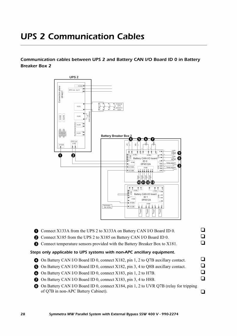
Communication cables between UPS 2 and Battery CAN I/O Board ID 0 in Battery Breaker Box 2
Steps only applicable to UPS systems with non-APC ancillary equipment.
Connect X133A from the UPS 2 to X133A on Battery CAN I/O Board ID 0.
Connect X185 from the UPS 2 to X185 on Battery CAN I/O Board ID 0.
Connect temperature sensors provided with the Battery Breaker Box to X181.
On Battery CAN I/O Board ID 0, connect X182, pin 1, 2 to Q7B auxillary contact.
On Battery CAN I/O Board ID 0, connect X182, pin 3, 4 to Q8B auxillary contact.
On Battery CAN I/O Board ID 0, connect X183, pin 1, 2 to H7B.
On Battery CAN I/O Board ID 0, connect X183, pin 3, 4 to H8B.
On Battery CAN I/O Board ID 0, connect X184, pin 1, 2 to UVR Q7B (relay for tripping of Q7B in non-APC Battery Cabinet).
Con
nect
ion
plan
e0P
4627
X131
X130
X133A 21X185
UPS 2
EM
O (
Dis
play
)
X134A
X1281
2
X1291
2
Bac
kfee
d pr
otec
tion
EPO out
EPO out
X1771
2
X12
6B
X12
7BX
126A
X12
7A
X186
34
1 2 3 4X182
1 2 3X183
X133A
Battery CAN I/O boardID 1
0P4512A
4
12X
184X
180
14
23
Fuse
5
1 2 3 4
Fuse
6
5 6
Fuse
7
7 8
Fuse
8
X133BTerminator0M-1878A
Battery Breaker Box 2
12
X185
X186
Q7
1 2 3 4
Q8
X182
X133A
12
X185
Battery CAN I/O boardID 0
0P4512A
X18
01
42
3
X133B
Fuse
1
1 2
Fuse
2
3 4
Fuse
3
5 6
Fuse
4
7 8
1 2 3X183
H7
H8
4
+ - + -
31
Temp sensor+
+
42 -X18
1
Temp sensor
NTC
NTC-
31
Q8
Q7
UVR+
+4
2
UVR
-
-
X18
4
ExternalEPO
placed inroom
21 3 4
28 Symmetra MW Parallel System with External Bypass SSW 400 V - 990-2274

Communication Cables: UPS 2 Communication Cables
On Battery CAN I/O Board ID 0, connect X184, pin 3, 4 to UVR Q8B (relay for tripping of Q8B in non-APC Battery Cabinet).
On Battery CAN I/O Board ID 0, connect X186, pin 1, 2 to fuse indicator 1 on battery string (if available - if not connect jumper).
On Battery CAN I/O Board ID 0, connect X186, pin 3, 4 to fuse indicator 2 on battery string (if available - if not connect jumper).
On Battery CAN I/O Board ID 0, connect X186, pin 5, 6 to fuse indicator 3 on battery string (if available - if not connect jumper).
On Battery CAN I/O Board ID 0, connect X186, pin 7, 8 to fuse indicator 4 on battery string (if available - if not connect jumper).
Symmetra MW Parallel System with External Bypass SSW 400 V - 990-2274 29

Communication Cables: UPS 2 Communication Cables
Communication cables between Battery CAN I/O Board ID 0 and Battery CAN I/O Board ID 1 in Battery Breaker Box 2 (if available)
Steps only applicable to UPS systems with non-APC ancillary equipment.
Connect X133B from Battery CAN I/O Board ID 0 to X133A on Battery CAN I/O Board ID 1.
On Battery CAN I/O Board ID 1, connect terminator 0M-1878A to X133B.
On Battery CAN I/O Board ID 1, connect jumper from X180, pin 1 to X180, pin 2.
X1863
4
1 2 3 4X182
1 2 3X183
X133A
Battery CAN I/O boardID 1
0P4512A
4
12X
184X
180
14
23
Fuse
5
1 2 3 4
Fuse
6
5 6
Fuse
7
7 8
Fuse
8
X133BTerminator0M-1878A
Battery Breaker Box 2
12
X185
X186
Q7
1 2 3 4
Q8
X182
X133A
12
X185
Battery CAN I/O boardID 0
0P4512A
X18
01
42
3X133B
Fuse
1
1 2
Fuse
2
3 4
Fuse
3
5 6
Fuse
4
7 8
1 2 3X183
H7
H8
4
+ - + -
31
Temp sensor+
+
42 -X18
1
Temp sensor
NTC
NTC-
31
Q8
Q7
UVR+
+
42
UVR
-
-
X18
4
On Battery CAN I/O Board ID 1, connect X186, pin 1, 2 to fuse indicator 5 on battery string (if available - if not connect jumper).
On Battery CAN I/O Board ID 1, connect X186, pin 3, 4 to fuse indicator 6 on battery string (if available - if not connect jumper).
On Battery CAN I/O Board ID 1, connect X186, pin 5, 6 to fuse indicator 7 on battery string (if available - if not connect jumper).
On Battery CAN I/O Board ID 1, connect X186, pin 7, 8 to fuse indicator 8 on battery string (if available - if not connect jumper).
30 Symmetra MW Parallel System with External Bypass SSW 400 V - 990-2274
Communication Cables: UPS 2 Communication Cables
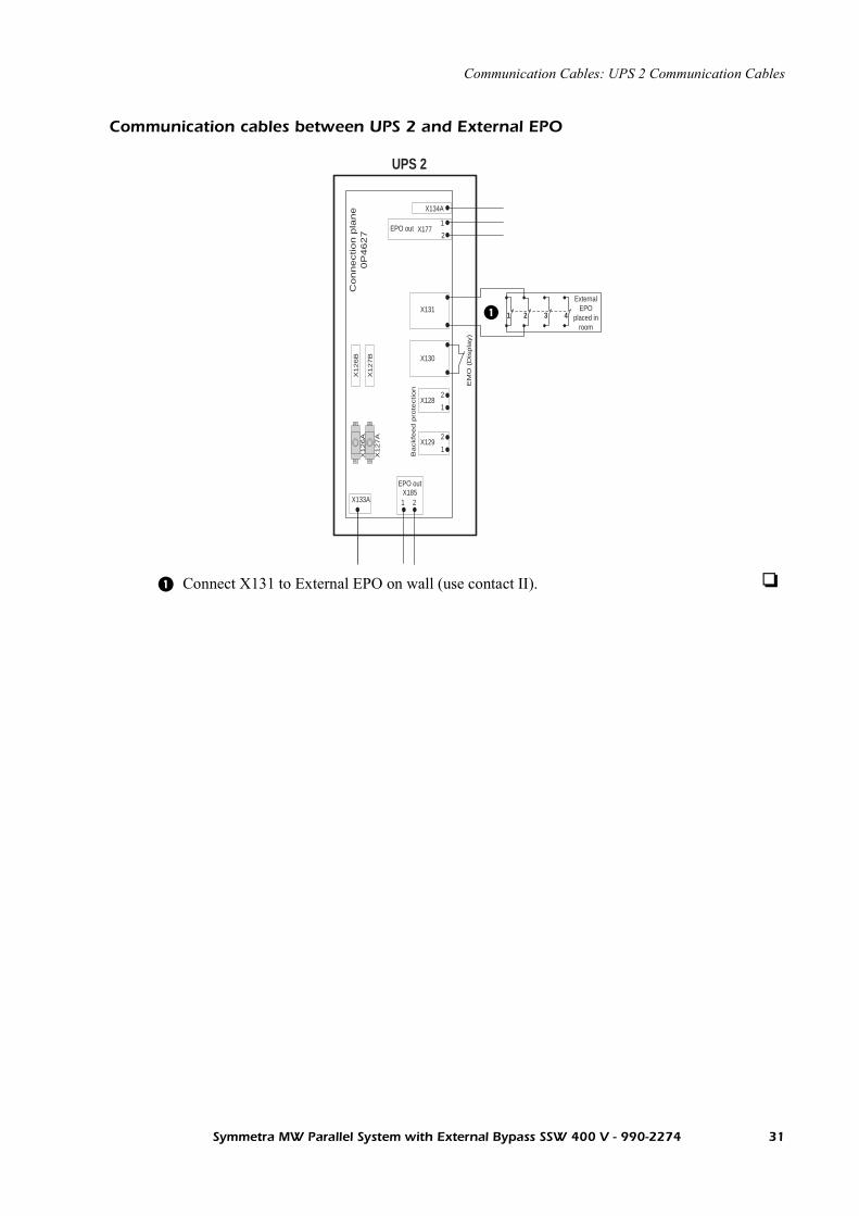
Communication cables between UPS 2 and External EPO
Connect X131 to External EPO on wall (use contact II).
Co
nn
ectio
n p
lan
e0
P4
62
7
X131
X130
X133A 21X185
UPS 2
EM
O (
Dis
pla
y)
X134A
X1281
2
X1291
2
Ba
ckfe
ed
pro
tectio
n
EPO out
EPO out
X1771
2
X1
26
B
X1
27
BX
12
6A
X1
27
A
ExternalEPO
placed inroom
21 3 4
Symmetra MW Parallel System with External Bypass SSW 400 V - 990-2274 31

Communication Cables: UPS 2 Communication Cables
Communication cables between UPS 2 and MBP CAN I/O Board UPS 2 in Maintenance Bypass Panel (MBP)
Steps only applicable to UPS systems with non-APC ancillary equipment.
Connect X134A from the UPS 2 to X134A on MBP CAN I/O Board UPS 2. In installations with optional Relay Board refer to Connecting Optional Relay Board section.
Connect X177 from UPS 2 to X177 on MBP CAN I/O Board UPS 2.
On MBP CAN I/O Board UPS 2, connect terminator 0M-1878A to X134B.
Con
nect
ion
plan
e0P
4627
X131
X130
X133A 21X185
UPS 2
EM
O (
Dis
play
)
X134A
X1281
2
X1291
2
Bac
kfee
d pr
otec
tion
EPO out
EPO out
MBP CAN I/O board 2
Maintenance Bypass Panel
0P4533A
C2
43
C1
21
X17
8
61
23
45
X17
3M
BP
Bre
aker
s
X17
6
87
109
1211
X134A
X134B
Terminator0M-1878A
56
Q2
34
12
Q1
X1771
2X177
1
2
H4H3
X175
12
Norm.op
Relay output
X174
12
Earth fault sensor
X172Lamps
X128
12
X129
124321 121187 10965
+ - + -
+
-
+-
+
-
+
-
-
+
X12
6B
X12
7BX
126A
X12
7A
1 42 3X170
Q1 B
Q2 B
Q3 2
Q4 2
Q5 2
Q6 2
ExternalEPO
placed inroom
1 2 3 4
+
-
Shunt trip 24V
External Lampsupply V or V
Max. 250V 5ADC
DC
AC
AC
On MBP CAN I/O Board UPS 2, connect X172, pin 3, 4 to H3 lamp.
On MBP CAN I/O Board UPS 2, connect X172, pin 5, 6 to H4 lamp.
On MBP CAN I/O Board UPS 2, connect X172, pin 11, 12 to external supply for lamp.
On MBP CAN I/O Board UPS 2, connect X173, pin 1, 2 to Q1B breaker indicator.
On MBP CAN I/O Board UPS 2, at X173, connect pin 3, 4 to Q2B breaker indicator. If Q2 is not available, connect jumper between pin 3 and 4.
On MBP CAN I/O Board UPS 2, connect X173, pin 5, 6 to Q3 breaker indicator (contact II).
On MBP CAN I/O Board UPS 2, connect X173, pin 7, 8 to Q4 breaker indicator (contact II). If Q4 is not available, connect jumper between pin 7 and 8.
32 Symmetra MW Parallel System with External Bypass SSW 400 V - 990-2274
Communication Cables: UPS 2 Communication Cables
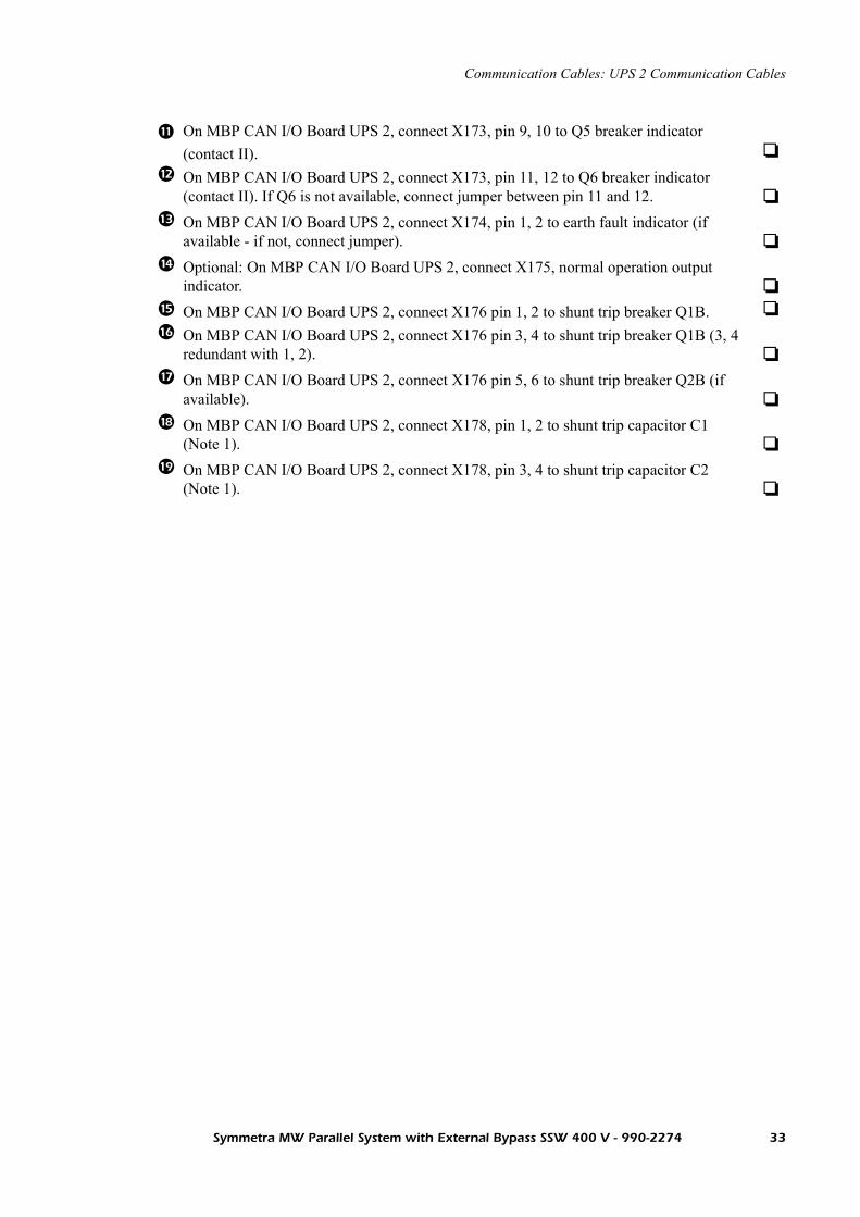
On MBP CAN I/O Board UPS 2, connect X173, pin 9, 10 to Q5 breaker indicator (contact II).
On MBP CAN I/O Board UPS 2, connect X173, pin 11, 12 to Q6 breaker indicator (contact II). If Q6 is not available, connect jumper between pin 11 and 12.
On MBP CAN I/O Board UPS 2, connect X174, pin 1, 2 to earth fault indicator (if available - if not, connect jumper).
Optional: On MBP CAN I/O Board UPS 2, connect X175, normal operation output indicator.
On MBP CAN I/O Board UPS 2, connect X176 pin 1, 2 to shunt trip breaker Q1B.
On MBP CAN I/O Board UPS 2, connect X176 pin 3, 4 to shunt trip breaker Q1B (3, 4 redundant with 1, 2).
On MBP CAN I/O Board UPS 2, connect X176 pin 5, 6 to shunt trip breaker Q2B (if available).
On MBP CAN I/O Board UPS 2, connect X178, pin 1, 2 to shunt trip capacitor C1 (Note 1).
On MBP CAN I/O Board UPS 2, connect X178, pin 3, 4 to shunt trip capacitor C2 (Note 1).
Symmetra MW Parallel System with External Bypass SSW 400 V - 990-2274 33

UPS 3 Communication Cables
Communication cables between UPS 3 and Battery CAN I/O Board ID 0 in Battery Breaker Box 3
Steps only applicable to UPS systems with non-APC ancillary equipment.
Connect X133A from the UPS 3 to X133A on Battery CAN I/O Board ID 0.
Connect X185 from the UPS 3 to X185 on Battery CAN I/O Board ID 0.
Connect temperature sensors provided with the Battery Breaker Box to X181.
On Battery CAN I/O Board ID 0, connect X182, pin 1, 2 to Q7C auxillary contact.
On Battery CAN I/O Board ID 0, connect X182, pin 3, 4 to Q8C auxillary contact.
On Battery CAN I/O Board ID 0, connect X183, pin 1, 2 to H7C.
On Battery CAN I/O Board ID 0, connect X183, pin 3, 4 to H8C.
On Battery CAN I/O Board ID 0, connect X184, pin 1, 2 to UVR Q7C (relay for tripping of Q7C in non-APC Battery Cabinet).
Con
nect
ion
plan
e0P
4627
X131
X130
X133A 21X185
UPS 3
EM
O (
Dis
play
)
X134A
X1281
2
X1291
2
Bac
kfee
d pr
otec
tion
EPO out
EPO out
X1771
2
X12
6B
X12
7BX
126A
X12
7A
X186
34
1 2 3 4X182
1 2 3X183
X133A
Battery CAN I/O boardID 1
0P4512A
4
12X
184X
180
14
23
Fuse
5
1 2 3 4
Fuse
6
5 6
Fuse
7
7 8
Fuse
8
X133BTerminator0M-1878A
Battery Breaker Box 31
2
X185
X186
Q7
1 2 3 4
Q8
X182
X133A
12
X185
Battery CAN I/O boardID 0
0P4512A
X18
01
42
3
X133B
Fuse
1
1 2
Fuse
2
3 4
Fuse
3
5 6
Fuse
4
7 8
1 2 3X183
H7
H8
4
+ - + -
31
Temp sensor+
+
42 -X18
1Temp sensor
NTC
NTC-3
1
Q8
Q7
UVR+
+4
2
UVR
-
-
X18
4
ExternalEPO
placed inroom
1 2 3 4
34 Symmetra MW Parallel System with External Bypass SSW 400 V - 990-2274

Communication Cables: UPS 3 Communication Cables
On Battery CAN I/O Board ID 0, connect X184, pin 3, 4 to UVR Q8C (relay for tripping of Q8C in non-APC Battery Cabinet).
On Battery CAN I/O Board ID 0, connect X186, pin 1, 2 to fuse indicator 1 on battery string (if available - if not connect jumper).
On Battery CAN I/O Board ID 0, connect X186, pin 3, 4 to fuse indicator 2 on battery string (if available - if not connect jumper).
On Battery CAN I/O Board ID 0, connect X186, pin 5, 6 to fuse indicator 3 on battery string (if available - if not connect jumper).
On Battery CAN I/O Board ID 0, connect X186, pin 7, 8 to fuse indicator 4 on battery string (if available - if not connect jumper).
Symmetra MW Parallel System with External Bypass SSW 400 V - 990-2274 35

Communication Cables: UPS 3 Communication Cables
Communication cables between Battery CAN I/O Board ID 0 and Battery CAN I/O Board ID 1 in Battery Breaker Box 3 (if available)
Steps only applicable to UPS systems with non-APC ancillary equipment.
Connect X133B from Battery CAN I/O Board ID 0 to X133A on Battery CAN I/O Board ID 1.
On Battery CAN I/O Board ID 1, connect terminator 0M-1878A to X133B.
On Battery CAN I/O Board ID 1, connect jumper from X180, pin 1 to X180, pin 2.
X186
34
1 2 3 4X182
1 2 3X183
X133A
Battery CAN I/O boardID 1
0P4512A
4
12X
184X
180
14
23
Fuse
5
1 2 3 4
Fuse
6
5 6
Fuse
7
7 8
Fuse
8X133B
Terminator0M-1878A
Battery Breaker Box 3
12
X185
X186
Q7
1 2 3 4
Q8
X182
X133A
12
X185
Battery CAN I/O boardID 0
0P4512A
X18
01
42
3
X133B
Fuse
1
1 2
Fuse
2
3 4
Fuse
3
5 6
Fuse
4
7 8
1 2 3X183
H7
H8
4
+ - + -
31
Temp sensor+
+
42 -X18
1
Temp sensor
NTC
NTC-
31
Q8
Q7
UVR+
+
42
UVR
-
-
X18
4
On Battery CAN I/O Board ID 1, connect X186, pin 1, 2 to fuse indicator 5 on battery string (if available - if not connect jumper).
On Battery CAN I/O Board ID 1, connect X186, pin 3, 4 to fuse indicator 6 on battery string (if available - if not connect jumper).
On Battery CAN I/O Board ID 1, connect X186, pin 5, 6 to fuse indicator 7 on battery string (if available - if not connect jumper).
On Battery CAN I/O Board ID 1, connect X186, pin 7, 8 to fuse indicator 8 on battery string (if available - if not connect jumper).
36 Symmetra MW Parallel System with External Bypass SSW 400 V - 990-2274

Communication Cables: UPS 3 Communication Cables
Communication cables between UPS 3 and External EPO
Connect X131 to External EPO on wall (use contact III).
Connection p
lane
0P
4627
X131
X130
X133A 21X185
UPS 3
EM
O (
Dis
pla
y)
X134A
X1281
2
X1291
2
Backfe
ed p
rote
ction
EPO out
EPO out
X1771
2
X126B
X127B
X126A
X127A
ExternalEPO
placed inroom
1 2 3 4
Symmetra MW Parallel System with External Bypass SSW 400 V - 990-2274 37

Communication Cables: UPS 3 Communication Cables
Communication cables between UPS 3 and MBP CAN I/O Board UPS 3 in Maintenance Bypass Panel (MBP)
Steps only applicable to UPS systems with non-APC ancillary equipment.
Connect X134A from the UPS to X134A on MBP CAN I/O Board UPS 3. In installations with optional Relay Board refer to Connecting Optional Relay Board section.
Connect X177 from UPS 3 to X177 on MBP CAN I/O Board UPS 3.
On MBP CAN I/O Board UPS 3, connect terminator 0M-1878A to X134B.
Con
nect
ion
plan
e0P
4627
X131
X130
X133A 21X185
UPS 3
EM
O (
Dis
play
)
X134A
X1281
2
X1291
2
Bac
kfee
d pr
otec
tion
EPO out
EPO out
MBP CAN I/O board 3
Maintenance Bypass Panel
0P4533A
C2
43
C1
21
X17
8
61
23
45
X17
3M
BP
Bre
aker
s
X17
6
87
109
1211
X134A
X134B
Terminator0M-1878A
56
Q2
34
12
Q1
X1771
2X177
1
2
H4H3
X175
12
Norm.op
Relay output
X174
12
Earth fault sensor
X172Lamps
X128
12
X129
124321 121187 10965
+ - + -
+
-
+-
+
-
+
-
-
+
X12
6B
X12
7BX
126A
X12
7A
1 42 3X170
Q1 C
Q2 C
Q3 3
Q4 3
Q5 3
Q6 3
ExternalEPO
placed inroom
1 2 3 4
+
-
Shunt trip 24V
External Lampsupply V or V
Max. 250V 5ADC
DC
AC
AC
On MBP CAN I/O Board UPS 3, connect X172, pin 3, 4 to H3 lamp).
On MBP CAN I/O Board UPS 3, connect X172, pin 5, 6 to H4 lamp.
On MBP CAN I/O Board UPS 3, connect X172, pin 11, 12 to external supply for lamp.
On MBP CAN I/O Board UPS 3, connect X173, pin 1, 2 to Q1C breaker indicator.
On MBP CAN I/O Board UPS 3, at X173, connect pin 3, 4 to Q2C breaker indicator. If Q2 is not available, connect jumper between pin 3 and 4.
On MBP CAN I/O Board UPS 3, connect X173, pin 5, 6 to Q3 breaker indicator (contact III).
On MBP CAN I/O Board UPS 3, connect X173, pin 7, 8 to Q4 breaker indicator (contact III). If Q4 is not available, connect jumper between pin 7 and 8.
On MBP CAN I/O Board UPS 3, connect X173, pin 9, 10 to Q5 breaker indicator (contact III).
38 Symmetra MW Parallel System with External Bypass SSW 400 V - 990-2274

Communication Cables: UPS 3 Communication Cables
On MBP CAN I/O Board UPS 3, connect X173, pin 11, 12 to Q6 breaker indicator (contact III). If Q6 is not available, connect jumper between pin 11 and 12.
On MBP CAN I/O Board UPS 3, connect X174, pin 1, 2 to earth fault indicator (if available - if not, connect jumper).
Optional: On MBP CAN I/O Board UPS 3, connect X175, normal operation output indicator.
On MBP CAN I/O Board UPS 3, connect X176 pin 1, 2 to shunt trip breaker Q1C.
On MBP CAN I/O Board UPS 3, connect X176 pin 3, 4 to shunt trip breaker Q1C (3, 4 redundant with 1, 2).
On MBP CAN I/O Board UPS 3, connect X176 pin 5, 6 to shunt trip breaker Q2C (if available).
On MBP CAN I/O Board UPS 3, connect X178, pin 1, 2 to shunt trip capacitor C1 (Note 1).
On MBP CAN I/O Board UPS 3, connect X178, pin 3, 4 to shunt trip capacitor C2 (Note 1).
Symmetra MW Parallel System with External Bypass SSW 400 V - 990-2274 39

External Bypass Static Switch Communication Cables
Communication cables between External Bypass SSW and MBP CAN I/O Board Bypass SSW
Steps only applicable to UPS systems with non-APC ancillary equipment.
Connect X134A from the External Bypass SSW to X134A on MBP CAN I/O Board Bypass SSW.
Connect X177 from the External Bypass SSW to X177 on MBP CAN I/O Board Bypass SSW.
Connect X128 from the External Bypass SSW to X128 on MBP CAN I/O Board Bypass SSW.
Connect X129 from the External Bypass SSW to X129 on MBP CAN I/O Board Bypass SSW.
On MBP CAN I/O Board Bypass SSW, connect terminator 0M-1878 to X134B.
On MBP CAN I/O Board Bypass SSW, connect X172, pin 3, 4 to H3 lamp (contact IV).
On MBP CAN I/O Board Bypass SSW, connect X172, pin 5, 6 to H4 lamp (contact IV).
On MBP CAN I/O Board Bypass SSW, connect X172, pin 7, 8 to H5 lamp (contact IV).
On MBP CAN I/O Board Bypass SSW, connect X172, pin 9, 10 to H6 lamp (contact IV).
On MBP CAN I/O Board Bypass SSW, connect X173, pin 5, 6 to Q3 (contact IV).
0P46
27
X128
X12
6A
X12
7A
X129
X131
X130
1
2
1
2
Bac
k fe
ed1
Bac
k fe
ed2
EM
O (
Dis
play
)
X134A
X1771
2
X134A
X1281
2
X129
710
11
X17
3
MB
PB
reak
ers
X172Lamps
H6
109
H5
87
H4
65
H3
43 3 41 2
Q5
X176
11 1221
C2
43
C1
21
X17
8
X175
12
Norm.op
Relay output
X174
12
Earth fault sensor
5 6
Q6
X1771
2
912
86
54
32
1
21
0P4533
X134B
Terminator0M-1878A
+ - + - + - + -
+
-
-+
+ - + - + -
X12
6B
X12
7B
1 42 3X170
Q6
Q5
Q4
Q3
External Bypass Static Switch MBP CAN I/O Board Bypass SSW
ExternalEPO
placed onwall
1 2 3 4
Shunt trip forback feedprotection
24VDC
40 Symmetra MW Parallel System with External Bypass SSW 400 V - 990-2274

Communication Cables: External Bypass Static Switch Communication
Communication cables between External Bypass SSW and External EPO
On MBP CAN I/O Board Bypass SSW, connect X173, pin 7, 8 to Q4 (contact IV). If Q4 is not available, connect jumper between pin 7 and 8.
On MBP CAN I/O Board Bypass SSW, connect X173, pin 9, 10 to Q5 (contact IV).
On MBP CAN I/O Board Bypass SSW, connect X173, pin 11, 12 to Q6 (contact IV). If Q6 is not available, connect jumper between pin 11 and 12.
On MBP CAN I/O Board Bypass SSW, connect X174, pin 1, 2 to earth fault indicator (if available - if not, connect jumper).
Optional: On MBP CAN I/O Board Bypass SSW, connect X175, pin 1, 2, normal operation output indicator.
On MBP CAN I/O Board Bypass SSW, connect X176 pin 1, 2 to shunt trip breaker Q5.
On MBP CAN I/O Board Bypass SSW, connect X176 pin 3, 4 to shunt trip breaker Q5 (3, 4 redundant with 1, 2).
On MBP CAN I/O Board Bypass SSW, connect X176 pin 5, 6 to shunt trip breaker Q6 (if available).
On MBP CAN I/O Board Bypass SSW, connect X178, pin 1, 2 to shunt trip capacitor C1 (Note 1).
On MBP CAN I/O Board Bypass SSW, connect X178, pin 3, 4 to shunt trip capacitor C2 (Note 1).
Connect X131 from the External Bypass Static Switch to External EPO (use contact IV).
Con
nect
ion
plan
e0P
4627
External Bypass Static Switch
X128
X12
6A
X12
7A
X129
X131
X130
1
2
1
2
Bac
k fe
ed1
Bac
k fe
ed2
EM
O (
Dis
play
)
X134A
X1771
2
X12
6B
X12
7B
ExternalEPO
placed inroom
1 2 3 4
Symmetra MW Parallel System with External Bypass SSW 400 V - 990-2274 41


Technical Support
Note the UPS serial number (located behind the cover of the display) before calling technical support.Local, country-specific centers: go to www.apc.com/support/contact.
Europe, Middle East and Africa 00800 0272 0479
Symmetra MW Parallel System with External Bypass SSW 400 V - 990-2274 43