Embed Size (px)
Citation preview
Symbol Error Performance Analysis of OFDM Receiver
with Pulse Blanking over Frequency Selective Fading
Channel
Haitao. Liu1, Zhisheng. Yin
1, and Xuejun. Zhang
2
1 Tianjin Key Lab for Advanced Signal Processing, Civil Aviation University of China, Tianjin 30030, China
2 College of Electronic and Information Engineering, BeiHang University, Beijing 100191, China
Email: [email protected]; [email protected]; [email protected]
Abstract—Pulse blanking is a widely used method to eliminate
impulsive interference in orthogonal frequency division
multiplexing (OFDM) receiver. To analyze the effect of Inter
Carrier Interference (ICI) caused by pulse blanking on the
performance of symbol error rate (SER) for OFDM receiver, the
analytical expression of signal to noise ratio (SNR) for OFDM
receiver with pulse blanking is derived. The SER of OFDM
receiver with pulse blanking over AWGN, Rayleigh and Ricean
fading channel are also analyzed quantitatively based on the
SNR expression. Simulation results validate the accuracy of our
derived formulas. Index Terms—OFDM, impulse interference, pulse blanking;
SNR, SER, AWGN, rayleigh, ricean
I. INTRODUCTION
Orthogonal Frequency Division Multiplexing (OFDM)
is a multicarrier modulation technique which converts a
frequency-selective channel into a parallel collection of
frequency flat subchannels. OFDM has several
advantages over single-carrier communication systems,
such as spectral efficiency, efficient implementation
based on fast Fourier transform (FFT), and simple
channel equalization. Thus OFDM transmission scheme
is widely employed in wireless and wired
communications, e.g. Digital Subscriber Lines (DSL),
Digital Video Broadcasting (DVB), Digital Audio
Broadcasting (DAB), Wireless Local Area Networks
(WLAN), Power Line Communications (PLC), Long
Term Evolution (LTE), L-band Digital Aeronautical
Communication system (L-DACS) [1].
In general, OFDM systems are often exposed to
impulsive interference, e.g. ignition noise of passing
vehicles, powerline impulsive noise, or other systems
operating in the same frequency range. Some studies have
shown that the impulse interference with high power or
frequent occurrence can significantly affect the
performance of the OFDM receiver [2]-[4]. Thus, the
interference mitigation techniques have to be
implemented.
Manuscript received September 16, 2015; revised March 9, 2016. Corresponding author email: [email protected].
doi:10.12720/jcm.11.3.325-332
To improve the reliability of OFDM receiver exposed
to impulsive noise, an interference mitigation method
based on pulse blanking is firstly proposed in [5]. An
optimal threshold of pulse blanking is presented based on
the analytical expression of SNR for OFDM receiver [6].
With maximizing signal-to-interference-and-noise ratio
criterion, adaptive blanking threshold of impulse blanking
for OFDM receiver is proposed in [7]. To eliminate the
Inter Carrier Interference (ICI) caused by pulse blanking
of OFDM receiver, an iterative reconstructing and
subtracting ICI method is proposed in [8], [9], and a
frequency-domain ICI compensation scheme based on
FIR equalizer is also proposed in [10]. Based on
Bernoulli-Gaussian impulsive noise model, the
performance analysis of multicarrier and single carrier
communication systems is given in [2], [3], furthermore,
the influence of impulse noise on the SER performance of
multicarrier and single carrier communication systems is
also presented. The analytical expression of SNR for
OFDM receiver with impulse blanking is derived in
AWGN channel [11], however, the SER performance of
OFDM receiver with pulse blanking is not presented.
Unlike the method used in [11], in this paper, a new
analytical expression of SNR for OFDM receiver with
pulse blanking is derived. The SER performance of
OFDM receiver with pulse blanking over AWGN,
Rayleigh and Ricean fading channel are also derived
based on the SNR expression. Finally, the simulation
results validate the accuracy of our derived formulas.
II. SYSTEM MODEL
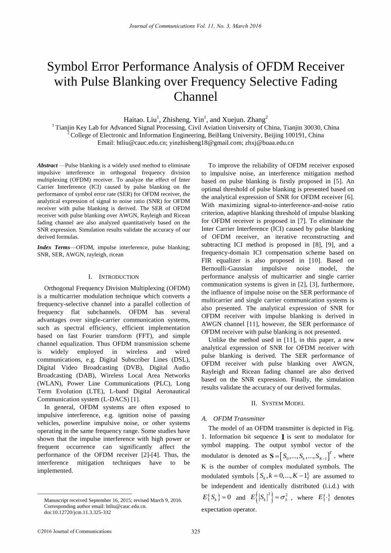
A. OFDM Transmitter
The model of an OFDM transmitter is depicted in Fig.
1. Information bit sequence I is sent to modulator for
symbol mapping. The output symbol vector of the
modulator is denoted as 0 1,..., ,...,T
k KS S S S , where
K is the number of complex modulated symbols. The
modulated symbols , 0,..., 1kS k K are assumed to
be independent and identically distributed (i.i.d.) with
0kE S and 2 2
k SE S , where E denotes
expectation operator.
325
Journal of Communications Vol. 11, No. 3, March 2016
©2016 Journal of Communications
I s xS ( )x t
Infor-
mation
source
Modu-
latorIFFT
Insert
CP
RF
front-
end
D/A
Conve
-rter
Fig. 1. Model of OFDM transmitter
The modulated symbol vector S is then transformed
into time domain by K-point inverse fast Fourier
Transform (IFFT). Thus the IFFT output signal vector
0 1,..., ,...,T
n Ks s s s is given by
H s F S (1)
where IFFT matrix HF is defined by
2
,
1, , 0, , 1
k nj
H Kn k e n k K
K
F (2)
with k being the subcarrier index in the frequency domain
and n denoting the sample index in the time domain.
Considering IFFT is an unitary transformation, the
statistical property of s agrees with S . Thus
, 0,..., 1ns n K are also i.i.d. with 0nE s and
2 2
n SE s .
After inserting Kg-point cyclic prefix, the transmitted
signal vector 0 1[x ,..., x ,..., x ]g
T
n K K x can be
expressed as
in x P s (3)
where inP is the cyclic prefix insertion matrix denoted as
( )
( )
g g g
g
K K K K
in
K K K K
0 IP
I (4)
The transmitted signal vector x is converted to analog
signal ( )x t by D/A converter and then ( )x t is
transformed into RF signal by RF front-end. Finally, the
RF signal is sent to channel by transmitter antenna.
B
z yr Y
RF
front-
end
A/D
Conv-
ertor
Rem-
ove
CP
Pulse
Blank-
ing
Equal-
izerFFT
( )r t y I
Infor-
mation
source
Demo-
dulat-
or
Interf-
erence
Detec-
tor
Channel
Estimat-
ion
kH
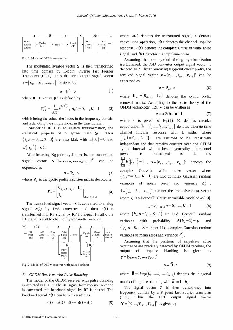
Fig. 2. Model of OFDM receiver with pulse blanking
B. OFDM Receiver with Pulse Blanking
The model of the OFDM receiver with pulse blanking
is depicted in Fig. 2. The RF signal from receiver antenna
is converted into baseband signal by RF front-end. The
baseband signal ( )r t can be represented as
( ) ( ) ( ) ( ) ( )r t x t h t n t i t (5)
where ( )x t denotes the transmitted signal, denotes
convolution operation, ( )h t denotes the channel impulse
response, ( )n t denotes the complex Gaussian white noise
signal, and ( )i t denotes the impulsive noise.
Assuming that the symbol timing synchronization
isestablished, the A/D converter output signal vector is
denoted as r . After removing Kg-point cyclic prefix, the
received signal vector 0 1[ ,..., ,..., ]T
n Kz z z z can be
expressed as
out z P r (6)
where [ ]gout K K KP 0 I denotes the cyclic prefix
removal matrix. According to the basic theory of the
OFDM technology [12], z can be written as
z s h n i (7)
where s is given by Eq.(1), denotes circular
convolution, 0 1,..., ,...,l Lh h h h denotes discrete-time
channel impulse response with L paths, where
, 0,..., 1lh l L are assumed to be statistically
independent and that remains constant over one OFDM
symbol interval., without loss of generality, the channel
power is normalized to 1, i.e.
1
2
0
1L
l
l
E h
,0 1[ ,..., ,..., ]T
n Kn n n n denotes the
complex Gaussian white noise vector where
, 0,..., 1nn n K are i.i.d complex Gaussian random
variables of mean zeros and variance 2
n ,
0 1,..., ,...,T
n Ki i i i denotes the impulsive noise vector
where ni is a Bernoulli-Gaussian variable modeled as[10]
, 0,1,..., 1n n ni b g n K (8)
where , 1,..., 1nb n K are i.i.d. Bernoulli random
variables with probability rP 1nb p and
, 0,..., 1ng n K are i.i.d. complex Gaussian random
variables of mean zeros and variance 2
g .
Assuming that the positions of impulsive noise
occurrence are precisely detected by OFDM receiver, the
output of impulse blanking is given as
0 1[y ,..., y ,..., y ]T
n Ky
y B z (9)
where 0 1,..., ,...,n Kdiag b b b B denotes the diagonal
matrix of impulse blanking with 1n nb b .
The signal vector y is then transformed into
frequency domain by a K-point fast Fourier transform
(FFT). Thus the FFT output signal vector
0 1,..., ,...,T
k KY Y Y Y is given by
326
Journal of Communications Vol. 11, No. 3, March 2016
©2016 Journal of Communications
Y = F y (10)
where the FFT matrix F is defined by
2
,
1, , 0,..., 1
k nj
Kk n e k n K
K
F (11)
Assuming that ideal channel estimation is employed,
the output of linear forced zero equalizer is given as
0 1[ ,..., ,..., ]T
k KY Y Y Y , where kY denotes the output of
k-th subchannel, which is given by
*
2, 0,..., 1k
k k
k
HY Y k N
H (12)
The signal vector Y is sent to demodulator, finally, the
demodulator output bit sequence I is sent to the sink.
III. PERFORMANCE ANALYSIS
A. SNR for OFDM Demodulator with Pulse Blanking
Substituting Eq. (7) into Eq. (9), the output signal
vector of pulse blanking can be represented as
y B s h B n B i (13)
where 0 0 1 1diag ,..., ,...,n n K Kb i b i b i B i with the
n-th term represented as
1 , 0,1,..., 1n n n n nb i b b g n K (14)
Since nb is a Bernoulli random variable with value one
or zero, the product 1 n nb b identically equals to 0.
Thus, 0, 0,1,..., 1n nb i n K , and then B i 0 .
Given all above, Eq. (13) is further simplified as
y s h i n (15)
where i B I s h denotes the equivalent
impulse noise vector with the n-th component ni
represented as
1
mod0
K
n n m n m Km
i b s h
(16)
and n B n denotes the complex Gaussian white noise
vector at the output of pulse blanking with the n-th
component nn represented as
1n n nn b n (17)
Substituting Eq. (14) into Eq. (10) yields
Y S H F i F n (18)
where 0 1,.., ,...,k Kdiag H H H H denotes the
frequency domain channel transfer matrix where kH
denotes the frequency response of the k-th subchannel.
Expanding Eq. (18), the k-th component of Y can be
expressed as
1 12 2
0 0
1 1k n k nK Kj jK K
k k k n n
n n
Y S H i e n eK K
(19)
From Eq. (19), kY can be split into two parts. The first
part contains the desired signal of the k-th subchannel,
which is defined as kE , and the second part contains
noise and the ICI caused by pulse blanking, which is
defined as kW . kY can be further expressed as
k k kY E W (20)
where
k k kE S H (21)
1 12 2
0 0
1 1k n k nK Kj jK K
k n n
n n
W i e n eK K
(22)
The variance of kE is calculated as
2 2
ar k k SV E H (23)
According to appendix A, the variance of kW can be
calculated as
2 21ar k S nV W p p (24)
Combining Eq. (22) and Eq. (23), the instantaneous
Signal-to-Noise Ratio (SNR) of the k-th subchannel for
OFDM receiver with pulse blanking is given by
22
2 2
( )SNR
( )
, 0,..., 11
ar k
k
ar k
S
k
S n
V E
V W
H k Kp p
(25)
B. SER of OFDM Receiver with Pulse Blanking over
AWGN Channel
In terms of AWGN channel, the channel transfer
matrix 0 1diag ,.., ,...,k KH H H H is a K K
identity diagonal matrix. According to Eq.(24), the SNR
of the k-th subchannel for OFDM receiver with pulse
blanking is given by
2
/ 2 2, 0,..., 1
1
S
k B
S n
k Kp p
(26)
By using the result in [13], the SER of the k-th
subchannel for OFDM receiver with pulse blanking in
case of M-PSK modulation can be expressed as
2
1
, / 20
sin π1exp d
sin
M MMPSK
k AWGN k B
MP
(27)
And the SER of the k-th subchannel for OFDM
receiver with pulse blanking in case of M-QAM
modulation can be expressed as
327
Journal of Communications Vol. 11, No. 3, March 2016
©2016 Journal of Communications
/
,
/
314
1
311
1
MQAM k B
k AWGN
k B
MP Q
MM
MQ
MM
(28)
where Q is the Gaussian Q-function defined as [14]
2
2
20
1exp d
2sin
xQ x
(29)
Considering each subchannel of OFDM receiver has
the same SER performance, the average SER is obtained
as
1
,
0
,
1 K
AWGN k AWGN
k
k AWGN
P PK
P
(30)
where ,k AWGN is given by Eq. (27) or (28). Based on
Eq. (27), (28) and (30), the following analysis can be
observed:
(1) In the SER expressions given in Eq. (27) and
Eq.(28), the SER of the k-th subchannel is independent of
subchannel index k, which indicates that the pulse
blanking has same effect on the error performance of
each subchannel of OFDM receiver;
(2) For the special case of no interference, i.e., p 0 ,
Eq.(30) reduces to the analytical expression of SER for
conventional OFDM receiver.
(3) For p 0 , in the limiting case S nSNR 2 2
approaches infinity, /lim 1k BSNR
p
, the SER in Eq.(30)
is determined only by the parameter p, therefore, there
will be an error floor for the SER performance curve.
C. SER of OFDM Receiver with Pulse Blanking over
Rayleigh Fading Channel
For the Rayleigh fading channel, the discrete-time
channel impulse response , 0,..., 1lh l L are
assumed to be i.i.d. complex Gaussian random variables,
i.e., 2~ 0, , 0,..., 1l lh l L and
12
0
1L
l
l
.
Hence, the frequency response of the k-th subchannel
1 2
0
klL jK
k l
l
H h e
is distributed according to complex
Gaussian of mean zeros and variance one. Furthermore, 2| |kH is distributed according to 2 with 2 degrees of
freedom and 2| | 1kE H .
According to Eq. (25), the instantaneous SNR of the k-
th subchannel for OFDM receiver with pulse blanking
over Rayleigh fading channel can be expressed as
22
/ 2 2, 0,..., 1
1
S
k B k
S n
H k Kp p
(31)
Considering 2 2 21S S np p is a constant
when the probability of impulsive noise occurrence p is
given, /k B is also distributed according to 2 with 2
degrees of freedom as well as 2| |kH . Then the average
SNR of the k-th subchannel for OFDM receiver with
pulse blanking can be obtained as
2
/ 2 2, 0,..., 1
1
S
k B
S n
k Kp p
(32)
By using the result in [13], the probability density
function of /k B is given by
/
/
/ /
/
1, 0
k B
k B
k B k B
k B
p e
(33)
By using the result in [14], the SER of the k-th
subchannel for OFDM receiver with pulse blanking in
case of M-PSK modulation over Rayleigh fading channel
can be expressed as
/
,
/
1 /
/
11
1 1 π
πtan cot
2 1
MPSK k B
k Rayleigh
k B
k B
k B
aM MP
M a M
a
a M
(34)
where 2sina M . The SER of the k-th subchannel
for OFDM receiver with pulse blanking in case of M-
QAM modulation over Rayleigh fading channel can be
expressed as
,
2
1
12 1
1 41 tan 1
π
MQAM
k Rayleigh
MP
M
M
M
(35)
where /
/
1.5
1 1.5
k B
k BM
.Thus the average SER is
obtained as
1
,
0
,
1 K
Rayleigh k Rayleigh
k
k Rayleigh
P PK
P
(36)
where ,k RayleighP is given by Eq. (34) or (35). We can
observe that the SER expresses given in Eq. (34~36)
support the analysis presented in section 3.2.
D. SER of OFDM Receiver with Pulse Blanking over
Ricean Fading Channel
For the Ricean fading channel, 0h is assumed to be
non-zero mean complex Gaussian random variable, i.e.,
328
Journal of Communications Vol. 11, No. 3, March 2016
©2016 Journal of Communications
~ , ,h u u 20 0 0 , , 1,..., 1lh l L are assumed
to be complex Gaussian random variables, i.e.,
2~ 0, , 1,..., 1l lh l L . The channel power is
normalized to 1, i.e.,
12 2
0
1L
l
l
u
, and the Ricean
factor is defined as
12 2
0
L
rice l
l
K u
. Hence, the
frequency response of the k-th subchannel kH is
distributed according to complex Gaussian with mean u
and variance
122
0
L
l
l
u
. Furthermore, 2| |kH is
distributed according to noncentral 2 with 2 degrees of
freedom and 2| | 1kE H .
According to (24), the instantaneous SNR of the k-th
subchannel for OFDM receiver with pulse blanking over
Ricean fading channel can be expressed as
22
/ 2 2, 0,..., 1
1
S
k B k
S n
H k Kp p
(37)
Considering 2 2 21S S np p is a constant
when the probability of impulsive noise occurrence p is
given, /k B is also distributed according to noncentral
2 with 2 degrees of freedom as well as 2| |kH . Then
the average SNR of the k-th subchannel for OFDM
receiver with pulse blanking /k B can be obtained as
2
/ 2 2, 0,..., 1
1
S
k B
S n
k Kp p
(38)
By using the result in [13], the probability density
function of /k Blank is given by
/
/
1
/
/
/
0
/
1
12
rice k B
k B
K
K
rice
k B
k B
rice rice k B
k B
K e ep
K KI
/, 0k B (39)
where 0I is the zero-order modified Bessel function of
the first kind. The Moment Generating Function (MGF)
of /k Blank is the Laplace transform of /k Bp with the
exponent reversed in sign, which can be obtained as
/
/ / /
0
/
/ /
1exp
1 1
k B
k B
s
k B k B
rice rice k B
rice k B rice k B
M s p e d
K K s
K s K s
(40)
By using the result in [14], the SER of the k-th
subchannel for OFDM receiver with pulse blanking in
case of M-PSK modulation over Ricean fading channel
can be expressed as
/
2
1 /M
, 20
πsin ( )
1= d
sink B
MMPSK
k RiceanMP M
(41)
the SER of the k-th subchannel for OFDM receiver with
pulse blanking in case of M-QAM modulation over
Ricean fading channel can be expressed as
/
/
/2
, 20
2
/4
20
4 1 3d
2 1 sinπ
4 1 3d
π 2 1 sin
k B
k B
MQAM
k Ricean
MP M
MM
MM
M M
(42)
Thus the average SER is obtained as
1
,
0
,
1 K
Ricean k Ricean
k
k Ricean
P PK
P
(43)
where ,k RiceanP is given by Eq. (40) or (41). We can
observe that the SER expressions given in Eq. (41~43)
also support the analysis presented in section 3.2.
IV. NUMERICAL RESULTS
A. System and Channel Parameters
TABLE I: SYSTEM AND CHANNEL PARAMETERS
Parameter name Value
System parameters
Modulator BPSK,16QAM
Signal bandwidth 8.192MHz
Subcarrier number 512
Data subcarrier number 512
Subcarrier interval 16KHz
Sample interval 0.122us
Cyclic prefix 16
Channel parameters
Channel models
AWGN,
Rayleigh (10 gains),
Ricean (10 gains), Krice = 5,10,15,20 dB
Impulsive noise model Bernoulli-Gaussian
Probability of interference Occurrence
P (shown in figs)
Receiver parameters
Channel estimation Ideal channel estimation
Channel equalization ZF-equalization
329
Journal of Communications Vol. 11, No. 3, March 2016
©2016 Journal of Communications
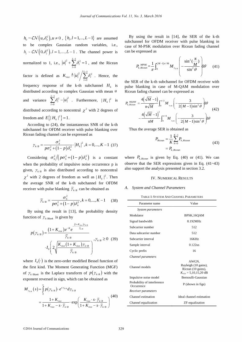
B. Symbol Error Performance Curves
In this section, we present some simulation results of
symbol error performance for AWGN, Rayleigh and
Ricean fading channels. Fig. 3-Fig. 8 show the theoretical
and simulated SER vs. SNR performance curves of
OFDM receiver with pulse blanking, where the SNR is
defined as log S nSNR 2 21010 . The theoretical
curves are obtained as follows: first, using the given
parameter p and input SNR, the average SNR of the k-th
subchannel for OFDM receiver with pulse blanking can
be obtained based on Eq. (26), (32) and (38), then, the
average SER can be obtained by using the average SNR
and Eq. (30), (36) and (43), finally, the theoretical SER
vs. SNR curves are plotted.
0 5 10 15 20 25 30 35 4010
-5
10-4
10-3
10-2
10-1
100
SNR(dB)
SE
R
theory,p=0
simulation,p=0
theory,p=0.01
simulation,p=0.01
theory,p=0.015
simulation,p=0.015
theory,p=0.02
simulation,p=0.02
Fig. 3. Symbol Error Ratio of OFDM receiver with pulse blanking (AWGN channel, 16QAM)
Fig. 3 shows the symbol error performance of OFDM
receiver with pulse blanking in case of 16QAM
modulation over AWGN channel. The figure contains
four pairs curves, which show the theoretical and
simulated SER of OFDM receiver with pulse blanking at
different p values. Based on the above observations, we
see that and simulation results show a good agreement
with theoretical calculation.
10 15 20 25 30 35 40 4510
-6
10-5
10-4
10-3
10-2
10-1
SNR(dB)
SE
R
theory,p=0
simulation,=0
theory,p=0.001
simulation,p=0.001
theory,p=0.005
simulation,p=0.005
theory,p=0.01
simulation,p=0.01
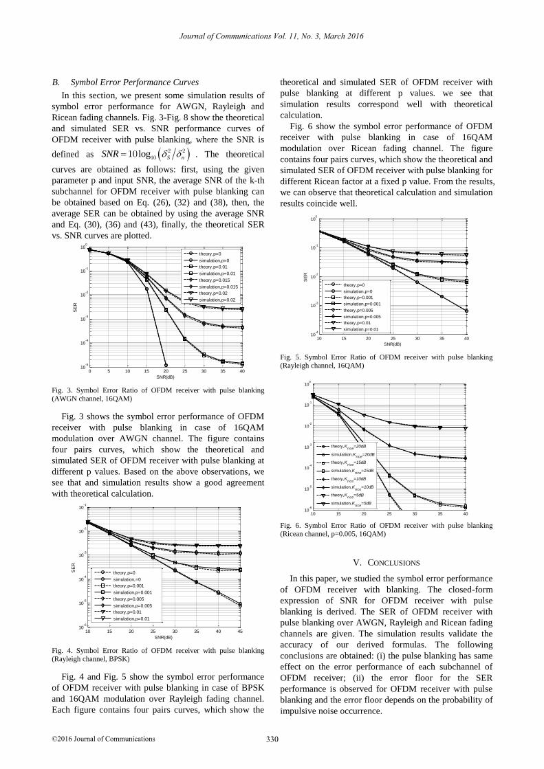
Fig. 4. Symbol Error Ratio of OFDM receiver with pulse blanking (Rayleigh channel, BPSK)
Fig. 4 and Fig. 5 show the symbol error performance
of OFDM receiver with pulse blanking in case of BPSK
and 16QAM modulation over Rayleigh fading channel.
Each figure contains four pairs curves, which show the
theoretical and simulated SER of OFDM receiver with
pulse blanking at different p values. we see that
simulation results correspond well with theoretical
calculation.
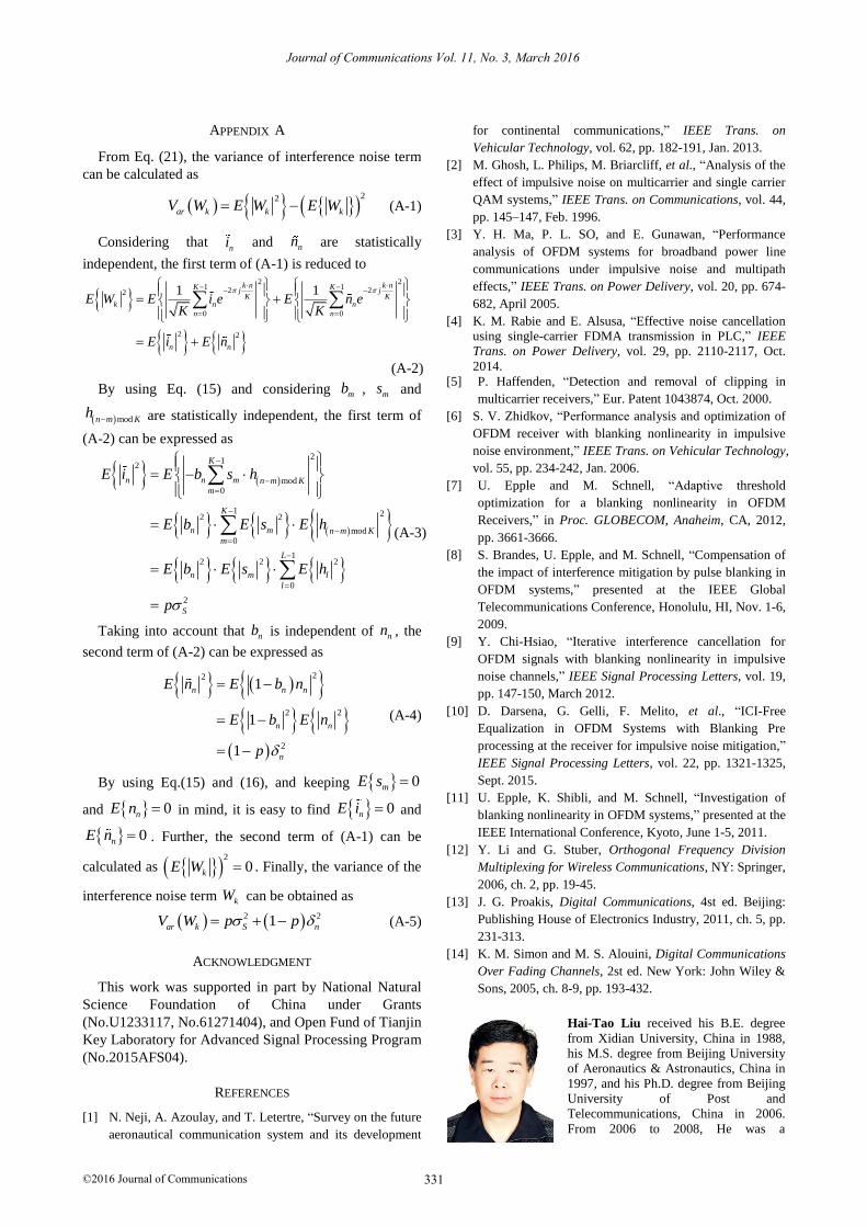
Fig. 6 show the symbol error performance of OFDM
receiver with pulse blanking in case of 16QAM
modulation over Ricean fading channel. The figure
contains four pairs curves, which show the theoretical and
simulated SER of OFDM receiver with pulse blanking for
different Ricean factor at a fixed p value. From the results,
we can observe that theoretical calculation and simulation
results coincide well.
10 15 20 25 30 35 4010
-4
10-3
10-2
10-1
100
SNR(dB)
SE
R
theory,p=0
simulation,p=0
theory,p=0.001
simulation,p=0.001
theory,p=0.005
simulation,p=0.005
theory,p=0.01
simulation,p=0.01
Fig. 5. Symbol Error Ratio of OFDM receiver with pulse blanking (Rayleigh channel, 16QAM)
10 15 20 25 30 35 4010
-6
10-5
10-4
10-3
10-2
10-1
100
theory,Krice
=20dB
simulatiion,Krice
=20dB
theory,Krice
=15dB
simulation,Krice
=15dB
theory,Krice
=10dB
simulation,Krice
=10dB
theory,Krice
=5dB
simulation,Krice
=5dB
Fig. 6. Symbol Error Ratio of OFDM receiver with pulse blanking
(Ricean channel, p=0.005, 16QAM)
V. CONCLUSIONS
In this paper, we studied the symbol error performance
of OFDM receiver with blanking. The closed-form
expression of SNR for OFDM receiver with pulse
blanking is derived. The SER of OFDM receiver with
pulse blanking over AWGN, Rayleigh and Ricean fading
channels are given. The simulation results validate the
accuracy of our derived formulas. The following
conclusions are obtained: (i) the pulse blanking has same
effect on the error performance of each subchannel of
OFDM receiver; (ii) the error floor for the SER
performance is observed for OFDM receiver with pulse
blanking and the error floor depends on the probability of
impulsive noise occurrence.
330
Journal of Communications Vol. 11, No. 3, March 2016
©2016 Journal of Communications
A
From Eq. (21), the variance of interference noise term
can be calculated as
22
ar k k kV W E W E W (A-1)
Considering that ni and nn are statistically
independent, the first term of (A-1) is reduced to
2 21 12 22
0 0
2 2
1 1k n k nK Kj jK K
k n n
n n
n n
E W E i e E n eK K
E i E n
(A-2)
By using Eq. (15) and considering mb , ms and
modn m Kh
are statistically independent, the first term of
(A-2) can be expressed as
21
2
mod0
1 22 2
mod0
12 2 2
0
2
K
n n m n m Km
K
n m n m Km
L
n m l
l
S
E i E b s h
E b E s E h
E b E s E h
p
(A-3)
Taking into account that nb is independent of nn , the
second term of (A-2) can be expressed as
22
2 2
2
1
1
1
n n n
n n
n
E n E b n
E b E n
p
(A-4)
By using Eq.(15) and (16), and keeping 0mE s
and 0nE n in mind, it is easy to find 0nE i and
0nE n . Further, the second term of (A-1) can be
calculated as 2
0kE W . Finally, the variance of the
interference noise term kW can be obtained as
2 21ar k S nV W p p (A-5)
ACKNOWLEDGMENT
This work was supported in part by National Natural
Science Foundation of China under Grants
(No.U1233117, No.61271404), and Open Fund of Tianjin
Key Laboratory for Advanced Signal Processing Program
(No.2015AFS04).
REFERENCES
[1] N. Neji, A. Azoulay, and T. Letertre, “Survey on the future
aeronautical communication system and its development
for continental communications,” IEEE Trans. on
Vehicular Technology, vol. 62, pp. 182-191, Jan. 2013.
[2] M. Ghosh, L. Philips, M. Briarcliff, et al., “Analysis of the
effect of impulsive noise on multicarrier and single carrier
QAM systems,” IEEE Trans. on Communications, vol. 44,
pp. 145–147, Feb. 1996.
[3] Y. H. Ma, P. L. SO, and E. Gunawan, “Performance
analysis of OFDM systems for broadband power line
communications under impulsive noise and multipath
effects,” IEEE Trans. on Power Delivery, vol. 20, pp. 674-
682, April 2005.
[4] K. M. Rabie and E. Alsusa, “Effective noise cancellation
using single-carrier FDMA transmission in PLC,” IEEE
Trans. on Power Delivery, vol. 29, pp. 2110-2117, Oct.
2014.
[5] P. Haffenden, “Detection and removal of clipping in
multicarrier receivers,” Eur. Patent 1043874, Oct. 2000.
[6] S. V. Zhidkov, “Performance analysis and optimization of
OFDM receiver with blanking nonlinearity in impulsive
noise environment,” IEEE Trans. on Vehicular Technology,
vol. 55, pp. 234-242, Jan. 2006.
[7] U. Epple and M. Schnell, “Adaptive threshold
optimization for a blanking nonlinearity in OFDM
Receivers,” in Proc. GLOBECOM, Anaheim, CA, 2012,
pp. 3661-3666.
[8] S. Brandes, U. Epple, and M. Schnell, “Compensation of
the impact of interference mitigation by pulse blanking in
OFDM systems,” presented at the IEEE Global
Telecommunications Conference, Honolulu, HI, Nov. 1-6,
2009.
[9] Y. Chi-Hsiao, “Iterative interference cancellation for
OFDM signals with blanking nonlinearity in impulsive
noise channels,” IEEE Signal Processing Letters, vol. 19,
pp. 147-150, March 2012.
[10] D. Darsena, G. Gelli, F. Melito, et al., “ICI-Free
Equalization in OFDM Systems with Blanking Pre
processing at the receiver for impulsive noise mitigation,”
IEEE Signal Processing Letters, vol. 22, pp. 1321-1325,
Sept. 2015.
[11] U. Epple, K. Shibli, and M. Schnell, “Investigation of
blanking nonlinearity in OFDM systems,” presented at the
IEEE International Conference, Kyoto, June 1-5, 2011.
[12] Y. Li and G. Stuber, Orthogonal Frequency Division
Multiplexing for Wireless Communications, NY: Springer,
2006, ch. 2, pp. 19-45.
[13] J. G. Proakis, Digital Communications, 4st ed. Beijing:
Publishing House of Electronics Industry, 2011, ch. 5, pp.
231-313.
[14] K. M. Simon and M. S. Alouini, Digital Communications
Over Fading Channels, 2st ed. New York: John Wiley &
Sons, 2005, ch. 8-9, pp. 193-432.
Hai-Tao Liu received his B.E. degree
from Xidian University, China in 1988,
his M.S. degree from Beijing University
of Aeronautics & Astronautics, China in
1997, and his Ph.D. degree from Beijing
University of Post and
Telecommunications, China in 2006.
From 2006 to 2008, He was a
331
Journal of Communications Vol. 11, No. 3, March 2016
©2016 Journal of Communications
PPENDIX A

postdoctoral fellow in Potevio Information Technology Co. Ltd.
China. He is a Professor in the School of Electronic and
Information Engineering in Civil Aviation University of
China , His research interests include aviation mobile
communications system and broadband mobile communication
system. The corresponding author. Email: [email protected].
Zhi-Sheng Yin was born in 1990. He is
currently a M.S. candidate in School of
Electronic and Information Engineering
in Civil Aviation University of China.
His recent research interests include
aviation mobile communications system.
Xue-Jun Zhang received his Ph.D.
degree from Beijing University of
Aeronautics & Astronautics, china in
2000. He is a Professor in the School of
Electronic and Information Engineering
in Beihang University. His research
interests include aviation mobile
communication systems and modern air
traffic management technology.
332
Journal of Communications Vol. 11, No. 3, March 2016
©2016 Journal of Communications

![Spectrally and Energy Efficient OFDM (SEE-OFDM) for Intensity … · 2015. 10. 29. · ACO-OFDM modulates only odd subcarriers [5] while DCO-OFDM modulates all subcarriers. Next,](https://img.pdfslide.us/doc/110x75/5fbf2c096a249726ce0f6214/spectrally-and-energy-eficient-ofdm-see-ofdm-for-intensity-2015-10-29-aco-ofdm.jpg)


![OFDM error floor based EVM estimation Error Floor Based EVM Estimation.pdfAWGN source producing the same BER (and EVM) degradation. [1]: The resulting EVM(BER) curves were verified](https://img.pdfslide.us/doc/110x75/5f2e7bc463c3260b31328bb2/ofdm-error-floor-based-evm-estimation-error-floor-based-evm-awgn-source-producing.jpg)


![New EfficientTiming and Frequency Error Estimation in OFDM sitivity of OFDM systems to frequency synchronization errors[3]. Carrier frequency offset if present causes a phase rotation](https://img.pdfslide.us/doc/110x75/5a78fcb17f8b9a68148d95c5/new-efcienttiming-and-frequency-error-estimation-in-ofdm-of-ofdm-systems-to-frequency.jpg)


![Coherent Detection of Turbo-Coded OFDM Signals … · an OFDM frame when it is not present) ... synchronization for OFDM are given in [15]– ... Detection of OFDM signals,](https://img.pdfslide.us/doc/110x75/5ae5fd777f8b9a08778c6dfc/coherent-detection-of-turbo-coded-ofdm-signals-ofdm-frame-when-it-is-not-present.jpg)