Embed Size (px)
Citation preview
bull 4 ASSEMBLER DIRECTIVES
bull
bull
bull ~
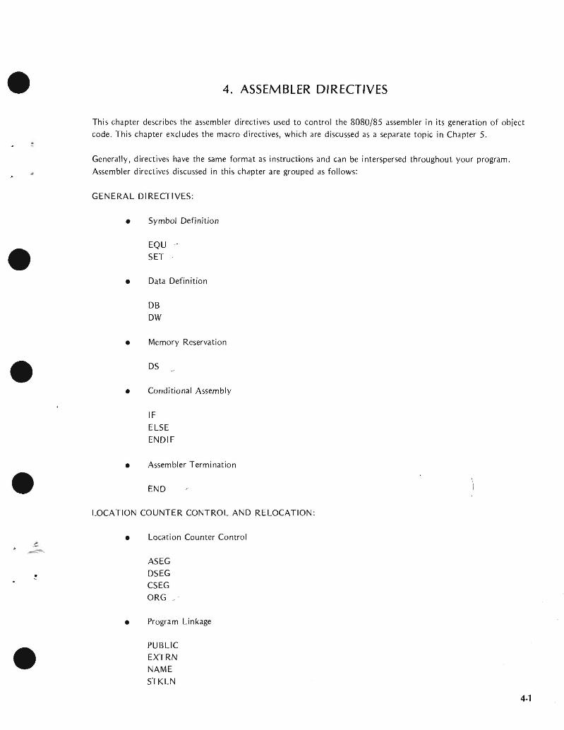
This chapter describes the assembler directives used to control the 808085 assembler in its generation of object code This chapter excl udes the macro directives which are discussed as a separate topic in Chapter 5
Generally directives have the same format as instructions and can be interspersed throughout your program
Assembler directives discussed in this chapter are grouped as follows
GENERAL DIRECTIVES
Symbol Definition bull EQU SET
Data Definition bull DB OW
Memory Reservation bull OS
Conditional Assembly bull IF
ELSE ENDIF
Assembler Termination bull END
LOCATION COUNTER CONTROL AND RELOCATION
bull Location Counter Control
ASEG DSEG CSEG ORG
Program Linkage bull
bull PUBLIC EXTRN NAME STKLN
4middot1
Chapter 4 Assembler Directives
Three assembler directives - EQU SET and MACRO - have a slightly different format from assembly language instructions The EQU SET and MACRO directives require a name for the symbol or macro being defined to be present in the label field Names differ from labels in that they must not be terminated with a bullcolon () as labels are Also the LOCAL and ENDM directives prohibit the use of the label field
The MACRO ENDM and LOCAL directives are explained in Chapter 5
SYMBOL DEFINITION
The assembler automatically assigns values to symbols that appear as instruction labels This val ue is the current
setting of the location counter when the instruction is assembled (The location counters are explained under
Address Control and Relocation later in this chapter )
You may define other symbols and assign them values by using the EQU and SET directives Symbols defined
using EQU cannot be redefined during assembly those defined by SET can be assigned new values by subsequent
SET directives
The name required in the label field of an EQU or SET directive must not be terminated with a colon
Symbols defined by EQU and SET have meaning throughout the remainder of the program This may cause the symbol to have illegal mUltiple definitions when the EQU or SET directive appears in a macro definition Use the LOCAL directive (described in Chapter 5) to avoid this problem
EQU Directive
EQU assigns the value of expression to the name specified in the label field
Label Opcode Operand
name EQU expression
The required name in the label field may not be terminated with a colon This name cannot be redefined by a subsequent EQU or SET directive The EQU expression cannot contain any external symbol (External symbols are explained under Location Counter Control and Relocation later in this chapter )
Assemblymiddottime evaluation of EQU expressions always generates a modulo 64K address Thus the expression
always yields a value in the range 0-65536
Example
The following EQU directive enters the name ONES into the symbol table and assigns the binary value 11111111 to it
ONES EQU OFFH
bull
bull
bull
4-2
Chapter 4 Assembler Directives
bull The value assigned by the EQU directive can be recalled in subsequent source lines by referring to its assigned name as in the following IF directive
IF TYPE EQ ONES
ENDIF
SET Directive
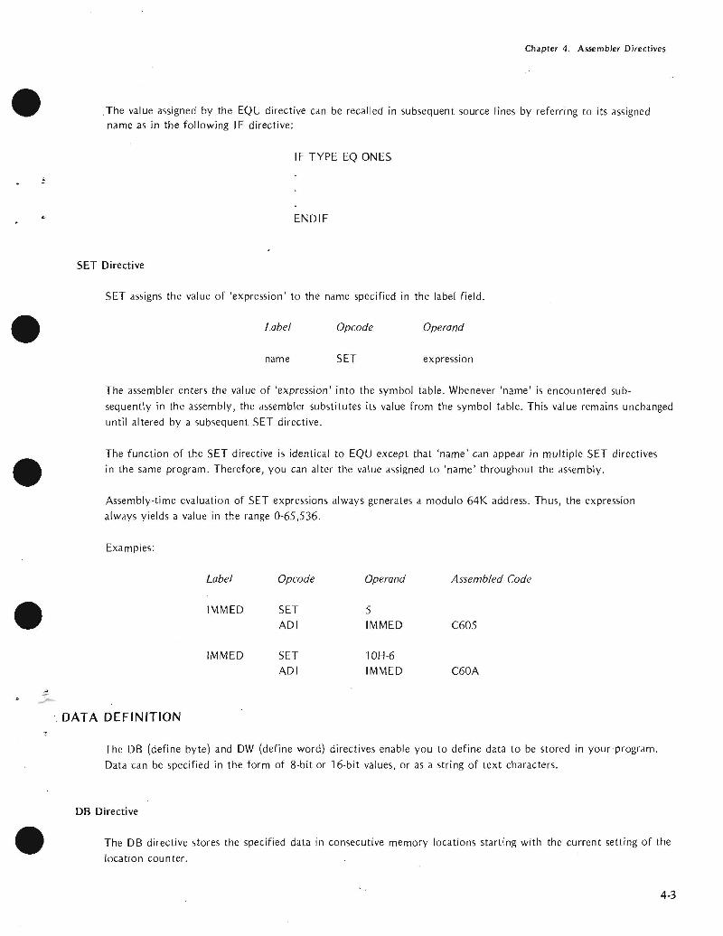
SET assigns the value of expression to the name specified in the label field
bull Label Opcode Operand
SET expression
The assembler enters the value of expression into the symbol table Whenever name is encountered subshy
sequently in the assembly the assembler substitutes its value from the symbol table This value remains unchanged until altered by a subsequent SET directive
bull The function of the SET directive is identical to EQU except that name can appear in mUltiple SET directives in the same program Therefore you can alter the value assigned to name throughout the assembly
Assembly-time evaluation of SET expressions always generates a modulo 64K address Thus the expression always yields a value in the range 0-65536
Examples
Label Opcode Operand Assembled Code
bull IMMED SET 5 ADI IMMED C605
IMMED SET lOH-6 ADI IMMED C60A
DATA DEFINITION
The DB (define byte) and DW (define word) directives enable you to define data to be stored in yourmiddotprogram
Data can be specified in the form of 8-bit or 16-bit values or as a string of text characters
bull DB Directive
The DB directive stores the specified data in consecutive memory locations starting with the current setting of the
location counter
4-3
Chapter 4 Assembler Directives
Label Opcode Operands bulloptional DB expression(s) or string(s)
The operand field of the DB directive can contain a list of expressions andor text strings The list can contain up to eight total items list items must be separated by commas Because of limited workspace the assembler may not be able to handle a total of eight items when the list includes a number of complex expressions If
you ever have this problem it is easily solved simply use two or more directives to shorten the list
Expressions must evaluate to 1-byte (8-bit) numbers in the range -256 through 255 Text strings may comprise a maximum of 128 ASCII characters enclosed in quotes
The assemblers relocation feature treats all external and relocatable symbols as 16-bit addresses When one of these symbols appears in an operand expression of the DB directive it must be preceded by either the HIGH or LOW operator to specify which byte of the address is to be used in the evaluation of the expression When neither operator is present the assembler assumes the LOW operator and issues an error message bull If the optional label is present it is assigned the starting val ue of the location counter and thus references the first byte stored by the DB directive Therefore the label STR in the following examples refers to the letter T of the string TIME
Examples
Label Opcode Operands Assembled Code
STR DB TIME 54494045 bull HERE DB OA3H A3
WOR01 DB -03H52 FOOA
OW Directive
The OW directive stores each 16-bit value from the expression list as an address The values are stored starting bullat the current setting of the location counter
Label Opcode Operands I
optional OW expression list I The least significant eight bits of the first value in the expression list are stored at the current setting of the location counter the most significant eight bits are stored at the next higher location This process is repeated for each item in the expression list
Expressions evaluate to 1-word (16-bit) numbers typically addresses If an expression evaluates to a single byte it is assumed to be the low order byte of a 16middotbit word where the high order byte is all zeros bull
44
Chapter 4 Assembler Directives
bull
bull
bull
bull
List items must be separated by commas The list can contain up to eight total items Because of limited workshyspace the assembler may not be able to handle eight complex expressions If you ever have this problem simply use two or more DW directives to shorten the list
The reversed order for storing the high and low order bytes is the typical format for addresses stored in memory Thus the OW directive is commonly used for storing address constants
Strings containing one or two ASCII characters enclosed in quotation marks l1)ay also appear in the expression
list When using such strings in your program remember that the characters are stored in reversed order
Specifying a string longer than two characters causes an error
If the optional label is present it is middotdssigned the starting address of the location counter and thus references the first byte stored by the OW directive (This is the low order byte of the first item in the expression list)
Examples
Assume that COMP and FILL are labels defined elsewhere in the program COMP addresses memory location 3B1CH FILL addresses memory location 3EB4H
Label Opcode Operands Assembled Code
AOOR1 OW COMP 1C3B
AOOR2 OW FILL B43E
STRNG DW AAB 41004241
FOUR OW 4H 0400
MEMORY RESERVATION
DS Directive
The DS directive can be used to define a block of storage
Label Opcode Operand
optional DS expression
The value of expression specifies the number of bytes to be reserved for data storage In theory this value may
range from OOH through OFFFFH in practice you will reserve no more stordge than will fit in your available memory and still leave room for the program
Any symbol appearing in the operand expression must be defined before the assembler reaches the DS directive
bull Unlike the DB dnd OW directives OS assembles no data into your program The contents of the reserved storage are unpredictable when program execution is initiated
4-5
Chapter 4 Assembler Directives
If the optional label is present it is assigned the current value of the location counter and thus references the first byte of the reserved memory block bullIf the value of the operand expression is zero no memory is reserved However if the optional label is present it is assigned the current value of the location counter
The OS directive reserves memory by incrementing the location counter by the value of the operand expression
Example
TTYBUF OS 72 RESERVE 72 BYTES FOR A TERMINAL OUTPUT BUFFER
Programming Tips Data Description and Access
Random Access Versus Read Only Memory
When coding data descriptions keep in mind the mix of ROM and RAM in your application
Generally the DB and OW directives define constants items that can be assigned to ROM You can use these items in your program but you cannot modify them If these items are assigned to RAM they have an initial value that your program can modify during execution Notice however that these initial values must be reloaded into memory prior to each execution of the program
Variable data in memory must be assigned to RAM
Data Description
Before coding your program you must have a thorough understanding of its input and output data But youll probably find it more convenient to postpone coding the data descriptions until the remainder of the program is fairly well developed This way you will have a better idea of the constants and workareas needed in your program Also the organization of a typical program places instructions in lower memory followed by the data followed by the stack
Data Access
Accessing data from memory is typically a two-step process First you tell the processor where to find the data then the processor fetches the data from memory and loads it into a register usually the accumulator Therefore the following code sequences have the identical effect of loading the ASCII character A into the accumulator
AAA DB A ALPHA DB ABC
bull
bull
bull
LXI BAAA LXI BALPHA LDAX B LDAX B bull
4-6
Chapter 4 Assembler Directives
In the the LXI instructions load the address of the desired data into the Band C registers The LDAX
instructions then load the accumulator with one byte of data from the address specified in the Band C
The assernbler neither knows nor cares that only one character from the threemiddotcharacter field ALPHA has been
accessed The program must account for the characters at ALPHA+j and ALPHA+2 as in the following coding
sequence
ALPHA DB ABC FINE ALPHA
LXI BALPHA ADDRESS OF ALPHA shy
LDAX B I ST ALPHA CHAR
INX B B TO ALPHA+j
LDAX B 2ND ALPHA CHAR
INX B B TO ALPHA+2 LDAX B 3RD ALPHA CHAR
The coding above is acceptable for short data fields like ALPHA For you can conserve memory
by setting up an instruction sequence that is executed until the source data is exhausted
Add Symbols for Data Access
The following example was nrcgtccgttgt earlier as an illustration of the DS directive
Label Opcode Comment
TTYBUF DS 72 TTY BUFFER
To access data in this buffer such as TTYBUF +1 TTYBUF+72 can be a laborious and confusing when you want only selected fields from the buffer You can simplify
this task by subdividing the buffer with the directive
Label Opcode Comment
TTYBUF DS 72 RVE TTY BUFFER
10 EQU TTYBUF RECORD IDENTIFIER
- NAME EQU TTYBUF+6 20middotCHAR NAME FIELD
NUMBER EQU TTYBUF+26 lOmiddotCHAR EMPLOYEE NUMBER
DEPT EQU TTYBUF+36 DEPARTMENT NUMBER
SSNO EQU TTYBUF+41 SEC NUMBER
DOH EQU TTYBUF+50 OF HIRE
DESC EQU TTYBUF+56 DESCRIPTION
4middot7
Chapter 4 Assembler Directives
Subdividing data as shown in the example simplifies data access and provides useful documentation throughout your program Notice that these EQU directives can be inserted anywhere within the program as you need them but coding them as shown in the example provides a more useful record description
CONDITIONAL ASSEMBLY
The I F ELSE and ENDIF directives enable you to assemble portions of your program conditionally that is only if certain conditions that you specify are satisfied
Conditional assembly is especially useful when your application requires custom programs for a number of comshy
mon options As an example assume that a basic control program requires customizing to accept input from one of six different sensing devices and to drive one of five different control devices Rather than code some thirty separate programs to account for all the possibilities you can code a single program The code for the inshydividual sensors and drivers must be enclosed by the conditional directives When you need to generate a custom program you can insert SET directives near the beginning of the source program to select the desired sensor and driver routines
IF ELSE ENDIF Directives
Because these directives arc used in conjunction they are described together here
Label Opcode Operand
optional IF expression
optional ELSE
optional ENDIF
The assembler evaluates the expression in the operand field of the IF directive If bit 0 of the resulting value is
one (TRUE ) all instructions between the IF directive and the next ELSE or ENDIF directive are assembled When bit 0 is zero (FALSE) these instructions are ignored (A TRUE expression evaluates to OFFFFH and FALSE to OH only bit zero need be tested)
All statements included between an IF directive and its required associated ENDIF directive are defined as an IF-ENDIF block The ELSE directive is optional and only one ELSE directive may appear in an IF-ENDIF block When included ELSE is the converse of IF When bit 0 of the expression in the IF directive is zero all statements between ELSE and the next ENDIF are assembled If bit 0 is one these statements are ignored
Operands are not allowed with the ELSE and ENDIF directives
An IF-EN D I F block may appear within another IF-END I F block These blocks can be nested to eight levels
Macro definitions (explained in the next chapter) may appear within an IF-ENDIF block Conversely IF-ENDIF blocks may appear within macro definitions In either case you must be certain to terminate the macro definition
bull
bull
bull
bull
bull 4-8
Chapter 4 Assembler Directives
bull or IF-ENDIF block so that it can be assembled completely For when a macro definition begins in an IF block but terminates after an ELSE only a portion of the macro can be assembled Similarly an
IF-ENDIF block within a macro definition must terminate within that same macro definition
NOTE
Caution is vhen symbols are defined in IF-ENDIF blocks and referenced elsewhere within the program These
symbols are undefined when the evaluation of the IF ex-suppresses the of the IF-ENDIF block
Example 1 Simple IF-ENDIF Block
bull COND1 IF TYPE EO 0
IF TYPE = 0
15 TRUE
ENDIF
2 IF -ELSE-ENDI F Block
bull COND2 IF TYPE 0
MBLED IF TYPE == 0 TRUE
ELSE
ASSEMBLED IF TYPE == 0 FALSE
bull ENDIF
bull 4-9
Chapter 4 Assembler Directives
-I
Example 3 Nested IFs
COND3 IF TYPE EO 0 bull ASSEMBLED IF TYPE = 0
IS TRUE
IF MODE EO 1
LEVEL ASSEMBLED IF TYPE = 0 AND MODE = l ARE BOTH
TRUE ENDIF ELSE
LEVEL ASSEMBLED IF TYPE 0
2 IS FALSE bull IF MODE EO 2
ASSEMBLED IF TYPE = 0 IS FALSE AND MODE = 2 IS TRUE
LEVEL ELSE
ASSEMBLED IF TYPE = 0 AND MODE = 2 ARE BOTH bullFALSE
ENDIF ENDIF
ASSEMBLER TERMINATION
END Directive bullThe END directive identifies the end of the source program and terminates each pass of the assembler
Label Opcode Operand
optional END expression
Only one END statement may appear in a source program and it must be the last source statement
If the optional expression is present its value is used as the starting address for program execution If no exmiddot pression is given the assembler assumes zero as the starting address
When a number of separate program modules are to be joined together only one may specify a program starting address The module with a starting address is the main module When source files are combined using the INshy
CLUDE control there are no restrictions on which source file contains the END bull 4-10
Chapter 4 Assembler Directives
bull END-OF-TAPE INDICATION
The EOT directive allows you to specify the physical end of paper tape to simplify assembly of multiple-tape source
programs
EOT Directive
Label Opcode Operand
optional EOT
When EOT is recognized by the assembler the message NEXT TAPE is sent to the console and the assembler pauses
After the next tape is loaded a space bar character rece ived at the console signals continuation of the assembly
bull Data in the operand field causes an error
LOCATION COUNTER CONTROL AND RELOCATION
All the directives discussed in the remainder of this chapter relate directly to program relocation except for the
ASEG and ORG directives These directives are described first for the convenience of readers who do not use the
relocation feature
bull Location Counter Control (Non-Relocatable Mode)
When you elect not to use the relocation feature an assembler default generates an ASEG directive for you The
ASEG directive specifies that the program is to be assembled in the non-relocatable mode and establishes a
location cou nter for the assembly
bull The location counter performs the same function for the assembler as the program counter performs during
execution It tells the assembler the next memory location available for instruction or data assembly
Initially the location counter is set to zero The location counter can be altered by the ORG (origin) directive
ORG Directive
The ORG directive sets the location counter to the value specified by the operand expression
Label Opcode Operand
optional ORG expression
The location counter is set to the value of the operand expression Assembly-time evaluation of ORG expressions
bull always yields a modulo 64K address Thus the expression always yields an address in the range 0 through
65535 Any symbol in the expression must be previously defined The next machine instruction or data item is
assembled at the specified address
4-11
Chapter 4 Assembler Directives
If no ORG directive is included before the first instruction or data byte in your program assembly begins at location zero
Your program can include any number of ORG directives Multiple ORGs need not specify addresses in ascending sequence but if you fail to do so you may instruct the assembler to write over some previously assembled portion of the program
If the optional label is present it is assigned the current value of the location counter before it is updated by the ORG directive
Example
Assume that the current value of the location counter is OFH (decimal 15) when the following ORG directive is encountered
PAG1 ORG OFFH ORG ASSEMBLER TO LOCATION
OFFH (decimal 225)
The symbol PAGI is assigned the address OFH The next instruction or data byte is assembled at location OFFH
Introduction to Relocatability
A major feature of this assembler is its system for creating relocatable object code modules Support for this new
feature includes a number of new directives for the assembler and three new programs included in ISIS-II The three new programs - LIB LINK and LOCATE _ arc described in the ISIS-Ii System Users Guide The new
assembler directives are described later in this chapter
Relocatability allows the programmer to code programs or sections of programs without worrying about the final arrangement of the object code in memory This offers developers of microcomputer systems major adshyvantages in two areas memory management and modular program development
Memory Management
When developing testing and debugging a system on your Intellec microcomputer development system your only concern with locating a program is that it doesnt overlap the resident routines of ISIS-II Because the Intellec system has 32K 48K or 64K of random access memory the location of your future program is not a great concern_ However the program you arc developing will almost certainly use some mix of random access memory (RAM) readmiddotonly memory (ROM) andor programmable read-only memory (PROM) Therefore the location of your program affects both cost dnd performance in your application The relocatability feature allows
you to develop test and debug your program on the Intellec development system and then simply relocate the object code to suit your application
The relocatability feature also has a major advantage at assembly-time often large programs with many symbols cannot be assembled because of limited work space for the symbol table Such a program can be divided into a
number of modules that can be assembled separately and then linked together to form a single object program
bull
bull
bull
bull
bull 4-12
Chapter 4 Assembler Directives
Modular Program Development
Although relocatability may seem to be a formidable term what it really means is that you can subdivide a
complex program into a number of smaller simpler programs This concept is best illustrated through the use of an example Assume thai a microcomputer program is to control the spark advance on an automobile engine This requires the program to sample the ambient air temperature engine air intake temperature coolant temperashyture manifold vacuum idle sensor and throttle sensor
Let us examine the approaches two different programmers might take to solve this problem Both programmers
want to calculate the degree of spark advance or retardation that provides the best fuel economy with the lowest
emissions Programmer A codes a single program that senses all inputs and calculates the correct spark advance
Programmer B uses a modular approach and codes separate programs for each input plus one program to calculate
spark advance
Although Programmer A avoids the need to learn to use the relocatability feature the modular approach used by Programmer B has a number of advantages you should consider
bull Simplified Program Development
It is generally easier to code test and debug several simple programs than one complex program
bull Sharing the Programming Task
If Programmer B finds that he is falling behind schedule he can assign one or more of his subshy
programs to another programmer Because of his single program concept Programmer A will
probably have to complete the program himself
bull Ease of Testing
Programmer B can lest and debug most of his modules as soon as they arc assembled Programmer
A must lest his program as a whol~ Notice that Programmer B has an extra advantage if the
sensors are being developed at the same lime as the program If one oflhe sensors is behind
schedule Programmer B can continue developing and testing programs for the sensors that arc
ready Because Programmer A cannot test his program until all the sensors are developed his
testing schedule is dependent on events beyond his control
bull Programming Changes
Given the nature of automotive design it is reasonable to expect some changes Juring system development If a change to one of the sensors requires a programming change Programmer A must search through his entire program to find and alter the coding for that sensor Then he must retest the entire program to be certain that those changes do not affect any of the other sensors
By contrast Programmer B need be concerned only with the module for that one sensor This
advantage continues throughout the life of the program
4middot13
Chapter 4 Assembler Directives
DIRECTIVES USED FOR RELOCATION
Several directives have been added to the assembler to support the relocation feature These fdll into the general
categories of location counter control and program linkage
Location Counter Control (Relocatable Programs)
Relocatable programs or program modules may use three locdtion counters The ASEG DSEG and CSEG
directive~ specify which location counter is to be used
The ASEG directive specifies dn dbsolute code segment Even in a relocdtable program module you may want to assign certain code segments to specific addresses For example restart routines invoked by the RST instrucshytion require specific addresses
The CSEG directive specifies a relocatable code segment In general the CSEG location counter is used for porshytions of the program that are to be in some form of read-only memory such as mdchine instructions and proshygram constants
The DSEG location counter specifies a relocdtdble data segment This location counter is used for program
elements that must be located in random access memory
These directives allow you to control program segmentation at assembly time The LOCATE program described in the ISIS-II System Users Guide gives you control over program segment location Therefore the guidelines given dbove are only generdl since they can be overridden by the LOCATE program
Regardless of how many times the ASEG CSEG and DSEG directives appear in your program the assembler produces a single contiguous module Th is module comprises four segments code data stack and memory The LINK and LOCATE programs are used to combine segments from individual modules and relocate them in
memory These programs are explained in the ISIS-II System Users Guide
ASEG Directive
ASEG directs the assembler to use the location counter for the dbsolute program segment
Label Opcode Operand
optional ASEG
Operands are not permitted with the ASEG directive
All instructions and data following the ASEG directive are dssembled in the absolute mode The ASEG directive
remains in effect until d CSEG or DSEG directive is encountered
The ASEG location counter has an initial value of zero The ORG directive can be used to dssign a new value to the ASEG location counter
bull
bull
bull
bull
bull 4-14
Chapter 4 Assembler Directives
When begins the assembler assurres the ASEG directive to be in effect Therefore a CSEG or DSEG
must the first instruction or data definition in a relocatable module If neither of these directives
appears in the program the entire program is assembltd in absolute mode and can be executed immediately
after without using the LINK or LOCATE programs
CSEG Directive
CSEG directs the assembler to assemble instructions and data in the relocatable mode the code
segment location counter
Label Opcode Operand
blank optional CSEG PAGE
INPAGE
When a program contains multiple CSEG all CSEG directives the program must specify
The operand of a CSEG directive has no effect on the current assembly but is stored with code to be to the LINK and LOCATE programs programs are described in the ISIS-II
The LOCATE program uses this information to determine relocation boundaries when it
joins this code segment to code segments from other programs The of the operand is as follows
bull blank This code segment may be relocated to the next available byte boundary
bull PAGE This code segment must when relocated boundaries
occur in multiples of 256 512 etc)
INPAGE -- This code segment must fit within a single page when relocated
The CSEG directive remains in effect until an ASEG or DSEG directive is encountered_
The code segment location counter has an initial value of zero The ORG directive can be used to a new
val ue to the CSEG location counter
DSEG Directive
DSEG directs the assembler to assemble subsequent instructions and data in the relocatable mode using the data
segment location counter
Label Operand
blank DSEG PAGE
INPAGE
When multiple DSEG directives appear in a program they must all specify the same throughout the
program The operands for the DSEG directive have the same meaning as for the CSEG directive except that
they apply to the data segment
4-15
Chapter 4 Assembler Directives
There is no interaction between the operands specified for the DSEG and CSEG directives Thus a code segment
can be byte relocatable while the data segment is page relocatable bull The DSEG directive remaim in effect IJntil an ASEG or CSEG directive is encountered
The data segment location counter has an initial value of zero The ORG directive can be used to assign a new
value to the DSEG location counter
ORG Directive (Relocalable Mode)
The ORG directive can be used to alter the value of the location counter presently in use
Label Opcode Operand
optional ORG expression bullThere are three location counters but only one location counter is in use at any given point in the program
Which one depends on whether the ASEG CSEG or DSEG directive is in effect
Any symbol used in the operand expression must have been previously defined An exception causes phase
errors for all labels that follow the ORG and a label error if the undefined error is defined later
When the ORG directive appears in a relocatable program segment the value of its operand expression must be
either absolute or relocatable within the current segment Thus if the ORG directive appears within a data segshy
ment the value of its expression must be relocatable within the data segment An error occurs if the expression bullevaluates to an address in the code segment
If the optional label is present it is assigned the current value of the location counter presently in use before
the ORG directive is executed
Program Linkage Directives
Modular programming and the relocation feature enable you to assemble and test a number of separate programs bullthat are to be joined together and executed as a single program Eventually it becomes necessary for these
separate programs to communicate information among themselves Establishing such communication is the
fu net ion of the program I inkage directives
A program may share its data addresses and instruction addresses with other programs Only items having an
entry in the symbol table can be shared with other programs therefore the item must be assigned a name or a
label when it is defined in the program I tems to be shared with other programs must be declared in a PUBLIC directive
Your program can directly access data or instructions defined in another program if you know the actual
address of the item but this is unlikely when both programs use relocation Your program can also gain access
to data or instructions declared as PUBLIC in other programs Notice however that the assembler normally
4-16
Chapter 4 Assembler Directives
flags as an error ltlny reference to ltl nltlme or lltlbel thltlt hltlS not been defined in your program To ltlvoid this
you must provide the assembler with ltl list of items used in your program but defined in some other program
These items must be declltlred in an EXTRN directive
The two remaining program linkage directives NAME and STKLN are individually explained later in this chltlpter
PUBLIC Directive
The PUBLIC directive makes each of the symbols listed in the operand field available for access by other programs
Label Opcode Operands
optionltll PUBLIC name-list
Each item in the operand name-list must be the name or label assigned to data or an instruction elsewhere in this program When multiple names appear in the list they must be seplttrated by commas Each nltlme may be declared PUBLIC only once in a program module Reserved words and externltll symbols (see the EXTRN directive below) cannot be declared to be PUBLIC symbols
PUBLIC directives may appear anywhere within a program module
if an item in the operand name-list has no corresponding entry in the symbol table (implying that it is undeshy
fined) it is flagged as an error
Example
PUBLIC SINCOSTANSQRT
EXTRN Directive
The EXTRN directive provides the assembler with a list of symbols referenced in this program but defined in a
different program Because of this the assembler establishes linkage to the other program and does not flag the
undefi ned references as errors
Label Opcode Operands
optional EXTRN name-list
Each item in the name-list identifies a symbol that may be referenced in this program but is defined in another program When multiple items appear in the list they must be separated by commas
If a symbol in the operand name-list is also defined in this program by the user or is a reserved symbol the effect
is the same as defining the same symbol more than once in a program The assembler flags this error
EXTRN directives may appear anywhere within a program module
A symbol may be declared to be external only once in a program module Symbols declared to be PUBLIC cannot also be declared to be EXTRN symbols
4-17
Chapter 4 Assembler Directives
If you omit a symbol from the name--list but reference it in the program the symbol is undefined The assembler
flags this error You may include symbols in the operand name--list that are not referenced in the program withshy bullout causing an error
Example
EXTRN ENTRYADDRTNBEGIN
NAME Directive
The NAME directive assigns a name to the object module generated by this assembly
Label Opcode Operand
optional NAME module-name bull The NAME directive requires the presence of a module-name in the operand field This name must conform to
the rules for defining symbols
Module names are necessary so that you can refer to a module and specify the proper sequence of modules
when a number of modules are to be bound together
The NAME directive must precede the first data or instruction coding in the source program but may follow
comments and control lines bullIf the NAME directive is missing from the program the assembler supplies a default NAME directive with the module-name MODULE This will cause an error if you attempt to bind together several object program modules and more than one has the name MODULE Also if you make an error coding the NAME directive the default name MODULE is assigned
The module - name assigned by the NAME directive appears as part of the page heading in the assembly listing
Example bullNAME MAIN
STKLN Directive
Regardless of the number of object program modules you may bind together only one stack is generated The
STKLN directive allows you to specify the number of bytes to be reserved for the stack for each module
Label Opcode Operand
optional STKLN expression
The operand expression must evaluate to a number which will be used as the maximum size of the stack bull 4middot18
Chapter 4 Assembler Directives
bull When the STKLN directive is omitted the provides a default STKLN of zero This is useful when multiple programs are bound only one stack will be so only one program module need
the stack size However you should provide a STKLN if your module is to be tested separately and uses the stack
If your program includes more than one STKLN directive the last value is retained
STKLN 100
STACI( and MEMORY Reserved Words
bull The reserved words STACK and MEMORY are not directives but are of interest to programmers using the relocation feature These reserved words are external references whose addresses are supplied by the LOCATE
program
STACK is the reference to the stack address You need this address to initialize the stack
pointer register Also you can base data structures on th is address symbolic references such as 5T ACK+1
etc
bull MEMORY is the symbolic reference to the first byte of unused memory the end of your program you can base data structures on this address symbolic such as MEMORY MEMORY+I etc
Programming Testing Rclocatable Modules
The ability to test individual program modules is a major of modular programming However many program modules are not self-sufficient and require some modification before they can be tested The following is a discussion of some of the more Common modifications that may be required
bull Initialization Routines
In most complete programs a number of or initialization are performed when execution first begins If the program module you are relies on initialization assigned to a different
you must duplicate those procedures in the module to be tested however that you can link any number of modules together for
One of the most important initialization is to set the stack The LOCATE program determines the origin of the stack
Your program should include the instruction to initialize the stack
LXI
bull 4middot19
Chapler 4 Assembler Direclives
InputOutput
When testing program modules it is likely that some input or output procedures appear in other modules Your bull program must simulate any of these procedures it needs to operate Since your Intellec development system
probably has considerably more random access memory than you need to test a program module you may be
able to simulate input and output data right in memory The LOCATE program supplies an address for the
reserved word MEMORY this is the address of the first byte of unused memory past the end of your program
You can access this memory using the symbolic reference MEMORY MEMORY+l and so on This memory can be used for storing test data or even for a program that generates test data
Remove Coding Used for Testing
After testing your program be certain to remove any code you inserted for testing In particular make certain that only one module in the complete program initializes the stack pointer bull
bull
bull
bull 4-20
Chapter 4 Assembler Directives
Three assembler directives - EQU SET and MACRO - have a slightly different format from assembly language instructions The EQU SET and MACRO directives require a name for the symbol or macro being defined to be present in the label field Names differ from labels in that they must not be terminated with a bullcolon () as labels are Also the LOCAL and ENDM directives prohibit the use of the label field
The MACRO ENDM and LOCAL directives are explained in Chapter 5
SYMBOL DEFINITION
The assembler automatically assigns values to symbols that appear as instruction labels This val ue is the current
setting of the location counter when the instruction is assembled (The location counters are explained under
Address Control and Relocation later in this chapter )
You may define other symbols and assign them values by using the EQU and SET directives Symbols defined
using EQU cannot be redefined during assembly those defined by SET can be assigned new values by subsequent
SET directives
The name required in the label field of an EQU or SET directive must not be terminated with a colon
Symbols defined by EQU and SET have meaning throughout the remainder of the program This may cause the symbol to have illegal mUltiple definitions when the EQU or SET directive appears in a macro definition Use the LOCAL directive (described in Chapter 5) to avoid this problem
EQU Directive
EQU assigns the value of expression to the name specified in the label field
Label Opcode Operand
name EQU expression
The required name in the label field may not be terminated with a colon This name cannot be redefined by a subsequent EQU or SET directive The EQU expression cannot contain any external symbol (External symbols are explained under Location Counter Control and Relocation later in this chapter )
Assemblymiddottime evaluation of EQU expressions always generates a modulo 64K address Thus the expression
always yields a value in the range 0-65536
Example
The following EQU directive enters the name ONES into the symbol table and assigns the binary value 11111111 to it
ONES EQU OFFH
bull
bull
bull
4-2
Chapter 4 Assembler Directives
bull The value assigned by the EQU directive can be recalled in subsequent source lines by referring to its assigned name as in the following IF directive
IF TYPE EQ ONES
ENDIF
SET Directive
SET assigns the value of expression to the name specified in the label field
bull Label Opcode Operand
SET expression
The assembler enters the value of expression into the symbol table Whenever name is encountered subshy
sequently in the assembly the assembler substitutes its value from the symbol table This value remains unchanged until altered by a subsequent SET directive
bull The function of the SET directive is identical to EQU except that name can appear in mUltiple SET directives in the same program Therefore you can alter the value assigned to name throughout the assembly
Assembly-time evaluation of SET expressions always generates a modulo 64K address Thus the expression always yields a value in the range 0-65536
Examples
Label Opcode Operand Assembled Code
bull IMMED SET 5 ADI IMMED C605
IMMED SET lOH-6 ADI IMMED C60A
DATA DEFINITION
The DB (define byte) and DW (define word) directives enable you to define data to be stored in yourmiddotprogram
Data can be specified in the form of 8-bit or 16-bit values or as a string of text characters
bull DB Directive
The DB directive stores the specified data in consecutive memory locations starting with the current setting of the
location counter
4-3
Chapter 4 Assembler Directives
Label Opcode Operands bulloptional DB expression(s) or string(s)
The operand field of the DB directive can contain a list of expressions andor text strings The list can contain up to eight total items list items must be separated by commas Because of limited workspace the assembler may not be able to handle a total of eight items when the list includes a number of complex expressions If
you ever have this problem it is easily solved simply use two or more directives to shorten the list
Expressions must evaluate to 1-byte (8-bit) numbers in the range -256 through 255 Text strings may comprise a maximum of 128 ASCII characters enclosed in quotes
The assemblers relocation feature treats all external and relocatable symbols as 16-bit addresses When one of these symbols appears in an operand expression of the DB directive it must be preceded by either the HIGH or LOW operator to specify which byte of the address is to be used in the evaluation of the expression When neither operator is present the assembler assumes the LOW operator and issues an error message bull If the optional label is present it is assigned the starting val ue of the location counter and thus references the first byte stored by the DB directive Therefore the label STR in the following examples refers to the letter T of the string TIME
Examples
Label Opcode Operands Assembled Code
STR DB TIME 54494045 bull HERE DB OA3H A3
WOR01 DB -03H52 FOOA
OW Directive
The OW directive stores each 16-bit value from the expression list as an address The values are stored starting bullat the current setting of the location counter
Label Opcode Operands I
optional OW expression list I The least significant eight bits of the first value in the expression list are stored at the current setting of the location counter the most significant eight bits are stored at the next higher location This process is repeated for each item in the expression list
Expressions evaluate to 1-word (16-bit) numbers typically addresses If an expression evaluates to a single byte it is assumed to be the low order byte of a 16middotbit word where the high order byte is all zeros bull
44
Chapter 4 Assembler Directives
bull
bull
bull
bull
List items must be separated by commas The list can contain up to eight total items Because of limited workshyspace the assembler may not be able to handle eight complex expressions If you ever have this problem simply use two or more DW directives to shorten the list
The reversed order for storing the high and low order bytes is the typical format for addresses stored in memory Thus the OW directive is commonly used for storing address constants
Strings containing one or two ASCII characters enclosed in quotation marks l1)ay also appear in the expression
list When using such strings in your program remember that the characters are stored in reversed order
Specifying a string longer than two characters causes an error
If the optional label is present it is middotdssigned the starting address of the location counter and thus references the first byte stored by the OW directive (This is the low order byte of the first item in the expression list)
Examples
Assume that COMP and FILL are labels defined elsewhere in the program COMP addresses memory location 3B1CH FILL addresses memory location 3EB4H
Label Opcode Operands Assembled Code
AOOR1 OW COMP 1C3B
AOOR2 OW FILL B43E
STRNG DW AAB 41004241
FOUR OW 4H 0400
MEMORY RESERVATION
DS Directive
The DS directive can be used to define a block of storage
Label Opcode Operand
optional DS expression
The value of expression specifies the number of bytes to be reserved for data storage In theory this value may
range from OOH through OFFFFH in practice you will reserve no more stordge than will fit in your available memory and still leave room for the program
Any symbol appearing in the operand expression must be defined before the assembler reaches the DS directive
bull Unlike the DB dnd OW directives OS assembles no data into your program The contents of the reserved storage are unpredictable when program execution is initiated
4-5
Chapter 4 Assembler Directives
If the optional label is present it is assigned the current value of the location counter and thus references the first byte of the reserved memory block bullIf the value of the operand expression is zero no memory is reserved However if the optional label is present it is assigned the current value of the location counter
The OS directive reserves memory by incrementing the location counter by the value of the operand expression
Example
TTYBUF OS 72 RESERVE 72 BYTES FOR A TERMINAL OUTPUT BUFFER
Programming Tips Data Description and Access
Random Access Versus Read Only Memory
When coding data descriptions keep in mind the mix of ROM and RAM in your application
Generally the DB and OW directives define constants items that can be assigned to ROM You can use these items in your program but you cannot modify them If these items are assigned to RAM they have an initial value that your program can modify during execution Notice however that these initial values must be reloaded into memory prior to each execution of the program
Variable data in memory must be assigned to RAM
Data Description
Before coding your program you must have a thorough understanding of its input and output data But youll probably find it more convenient to postpone coding the data descriptions until the remainder of the program is fairly well developed This way you will have a better idea of the constants and workareas needed in your program Also the organization of a typical program places instructions in lower memory followed by the data followed by the stack
Data Access
Accessing data from memory is typically a two-step process First you tell the processor where to find the data then the processor fetches the data from memory and loads it into a register usually the accumulator Therefore the following code sequences have the identical effect of loading the ASCII character A into the accumulator
AAA DB A ALPHA DB ABC
bull
bull
bull
LXI BAAA LXI BALPHA LDAX B LDAX B bull
4-6
Chapter 4 Assembler Directives
In the the LXI instructions load the address of the desired data into the Band C registers The LDAX
instructions then load the accumulator with one byte of data from the address specified in the Band C
The assernbler neither knows nor cares that only one character from the threemiddotcharacter field ALPHA has been
accessed The program must account for the characters at ALPHA+j and ALPHA+2 as in the following coding
sequence
ALPHA DB ABC FINE ALPHA
LXI BALPHA ADDRESS OF ALPHA shy
LDAX B I ST ALPHA CHAR
INX B B TO ALPHA+j
LDAX B 2ND ALPHA CHAR
INX B B TO ALPHA+2 LDAX B 3RD ALPHA CHAR
The coding above is acceptable for short data fields like ALPHA For you can conserve memory
by setting up an instruction sequence that is executed until the source data is exhausted
Add Symbols for Data Access
The following example was nrcgtccgttgt earlier as an illustration of the DS directive
Label Opcode Comment
TTYBUF DS 72 TTY BUFFER
To access data in this buffer such as TTYBUF +1 TTYBUF+72 can be a laborious and confusing when you want only selected fields from the buffer You can simplify
this task by subdividing the buffer with the directive
Label Opcode Comment
TTYBUF DS 72 RVE TTY BUFFER
10 EQU TTYBUF RECORD IDENTIFIER
- NAME EQU TTYBUF+6 20middotCHAR NAME FIELD
NUMBER EQU TTYBUF+26 lOmiddotCHAR EMPLOYEE NUMBER
DEPT EQU TTYBUF+36 DEPARTMENT NUMBER
SSNO EQU TTYBUF+41 SEC NUMBER
DOH EQU TTYBUF+50 OF HIRE
DESC EQU TTYBUF+56 DESCRIPTION
4middot7
Chapter 4 Assembler Directives
Subdividing data as shown in the example simplifies data access and provides useful documentation throughout your program Notice that these EQU directives can be inserted anywhere within the program as you need them but coding them as shown in the example provides a more useful record description
CONDITIONAL ASSEMBLY
The I F ELSE and ENDIF directives enable you to assemble portions of your program conditionally that is only if certain conditions that you specify are satisfied
Conditional assembly is especially useful when your application requires custom programs for a number of comshy
mon options As an example assume that a basic control program requires customizing to accept input from one of six different sensing devices and to drive one of five different control devices Rather than code some thirty separate programs to account for all the possibilities you can code a single program The code for the inshydividual sensors and drivers must be enclosed by the conditional directives When you need to generate a custom program you can insert SET directives near the beginning of the source program to select the desired sensor and driver routines
IF ELSE ENDIF Directives
Because these directives arc used in conjunction they are described together here
Label Opcode Operand
optional IF expression
optional ELSE
optional ENDIF
The assembler evaluates the expression in the operand field of the IF directive If bit 0 of the resulting value is
one (TRUE ) all instructions between the IF directive and the next ELSE or ENDIF directive are assembled When bit 0 is zero (FALSE) these instructions are ignored (A TRUE expression evaluates to OFFFFH and FALSE to OH only bit zero need be tested)
All statements included between an IF directive and its required associated ENDIF directive are defined as an IF-ENDIF block The ELSE directive is optional and only one ELSE directive may appear in an IF-ENDIF block When included ELSE is the converse of IF When bit 0 of the expression in the IF directive is zero all statements between ELSE and the next ENDIF are assembled If bit 0 is one these statements are ignored
Operands are not allowed with the ELSE and ENDIF directives
An IF-EN D I F block may appear within another IF-END I F block These blocks can be nested to eight levels
Macro definitions (explained in the next chapter) may appear within an IF-ENDIF block Conversely IF-ENDIF blocks may appear within macro definitions In either case you must be certain to terminate the macro definition
bull
bull
bull
bull
bull 4-8
Chapter 4 Assembler Directives
bull or IF-ENDIF block so that it can be assembled completely For when a macro definition begins in an IF block but terminates after an ELSE only a portion of the macro can be assembled Similarly an
IF-ENDIF block within a macro definition must terminate within that same macro definition
NOTE
Caution is vhen symbols are defined in IF-ENDIF blocks and referenced elsewhere within the program These
symbols are undefined when the evaluation of the IF ex-suppresses the of the IF-ENDIF block
Example 1 Simple IF-ENDIF Block
bull COND1 IF TYPE EO 0
IF TYPE = 0
15 TRUE
ENDIF
2 IF -ELSE-ENDI F Block
bull COND2 IF TYPE 0
MBLED IF TYPE == 0 TRUE
ELSE
ASSEMBLED IF TYPE == 0 FALSE
bull ENDIF
bull 4-9
Chapter 4 Assembler Directives
-I
Example 3 Nested IFs
COND3 IF TYPE EO 0 bull ASSEMBLED IF TYPE = 0
IS TRUE
IF MODE EO 1
LEVEL ASSEMBLED IF TYPE = 0 AND MODE = l ARE BOTH
TRUE ENDIF ELSE
LEVEL ASSEMBLED IF TYPE 0
2 IS FALSE bull IF MODE EO 2
ASSEMBLED IF TYPE = 0 IS FALSE AND MODE = 2 IS TRUE
LEVEL ELSE
ASSEMBLED IF TYPE = 0 AND MODE = 2 ARE BOTH bullFALSE
ENDIF ENDIF
ASSEMBLER TERMINATION
END Directive bullThe END directive identifies the end of the source program and terminates each pass of the assembler
Label Opcode Operand
optional END expression
Only one END statement may appear in a source program and it must be the last source statement
If the optional expression is present its value is used as the starting address for program execution If no exmiddot pression is given the assembler assumes zero as the starting address
When a number of separate program modules are to be joined together only one may specify a program starting address The module with a starting address is the main module When source files are combined using the INshy
CLUDE control there are no restrictions on which source file contains the END bull 4-10
Chapter 4 Assembler Directives
bull END-OF-TAPE INDICATION
The EOT directive allows you to specify the physical end of paper tape to simplify assembly of multiple-tape source
programs
EOT Directive
Label Opcode Operand
optional EOT
When EOT is recognized by the assembler the message NEXT TAPE is sent to the console and the assembler pauses
After the next tape is loaded a space bar character rece ived at the console signals continuation of the assembly
bull Data in the operand field causes an error
LOCATION COUNTER CONTROL AND RELOCATION
All the directives discussed in the remainder of this chapter relate directly to program relocation except for the
ASEG and ORG directives These directives are described first for the convenience of readers who do not use the
relocation feature
bull Location Counter Control (Non-Relocatable Mode)
When you elect not to use the relocation feature an assembler default generates an ASEG directive for you The
ASEG directive specifies that the program is to be assembled in the non-relocatable mode and establishes a
location cou nter for the assembly
bull The location counter performs the same function for the assembler as the program counter performs during
execution It tells the assembler the next memory location available for instruction or data assembly
Initially the location counter is set to zero The location counter can be altered by the ORG (origin) directive
ORG Directive
The ORG directive sets the location counter to the value specified by the operand expression
Label Opcode Operand
optional ORG expression
The location counter is set to the value of the operand expression Assembly-time evaluation of ORG expressions
bull always yields a modulo 64K address Thus the expression always yields an address in the range 0 through
65535 Any symbol in the expression must be previously defined The next machine instruction or data item is
assembled at the specified address
4-11
Chapter 4 Assembler Directives
If no ORG directive is included before the first instruction or data byte in your program assembly begins at location zero
Your program can include any number of ORG directives Multiple ORGs need not specify addresses in ascending sequence but if you fail to do so you may instruct the assembler to write over some previously assembled portion of the program
If the optional label is present it is assigned the current value of the location counter before it is updated by the ORG directive
Example
Assume that the current value of the location counter is OFH (decimal 15) when the following ORG directive is encountered
PAG1 ORG OFFH ORG ASSEMBLER TO LOCATION
OFFH (decimal 225)
The symbol PAGI is assigned the address OFH The next instruction or data byte is assembled at location OFFH
Introduction to Relocatability
A major feature of this assembler is its system for creating relocatable object code modules Support for this new
feature includes a number of new directives for the assembler and three new programs included in ISIS-II The three new programs - LIB LINK and LOCATE _ arc described in the ISIS-Ii System Users Guide The new
assembler directives are described later in this chapter
Relocatability allows the programmer to code programs or sections of programs without worrying about the final arrangement of the object code in memory This offers developers of microcomputer systems major adshyvantages in two areas memory management and modular program development
Memory Management
When developing testing and debugging a system on your Intellec microcomputer development system your only concern with locating a program is that it doesnt overlap the resident routines of ISIS-II Because the Intellec system has 32K 48K or 64K of random access memory the location of your future program is not a great concern_ However the program you arc developing will almost certainly use some mix of random access memory (RAM) readmiddotonly memory (ROM) andor programmable read-only memory (PROM) Therefore the location of your program affects both cost dnd performance in your application The relocatability feature allows
you to develop test and debug your program on the Intellec development system and then simply relocate the object code to suit your application
The relocatability feature also has a major advantage at assembly-time often large programs with many symbols cannot be assembled because of limited work space for the symbol table Such a program can be divided into a
number of modules that can be assembled separately and then linked together to form a single object program
bull
bull
bull
bull
bull 4-12
Chapter 4 Assembler Directives
Modular Program Development
Although relocatability may seem to be a formidable term what it really means is that you can subdivide a
complex program into a number of smaller simpler programs This concept is best illustrated through the use of an example Assume thai a microcomputer program is to control the spark advance on an automobile engine This requires the program to sample the ambient air temperature engine air intake temperature coolant temperashyture manifold vacuum idle sensor and throttle sensor
Let us examine the approaches two different programmers might take to solve this problem Both programmers
want to calculate the degree of spark advance or retardation that provides the best fuel economy with the lowest
emissions Programmer A codes a single program that senses all inputs and calculates the correct spark advance
Programmer B uses a modular approach and codes separate programs for each input plus one program to calculate
spark advance
Although Programmer A avoids the need to learn to use the relocatability feature the modular approach used by Programmer B has a number of advantages you should consider
bull Simplified Program Development
It is generally easier to code test and debug several simple programs than one complex program
bull Sharing the Programming Task
If Programmer B finds that he is falling behind schedule he can assign one or more of his subshy
programs to another programmer Because of his single program concept Programmer A will
probably have to complete the program himself
bull Ease of Testing
Programmer B can lest and debug most of his modules as soon as they arc assembled Programmer
A must lest his program as a whol~ Notice that Programmer B has an extra advantage if the
sensors are being developed at the same lime as the program If one oflhe sensors is behind
schedule Programmer B can continue developing and testing programs for the sensors that arc
ready Because Programmer A cannot test his program until all the sensors are developed his
testing schedule is dependent on events beyond his control
bull Programming Changes
Given the nature of automotive design it is reasonable to expect some changes Juring system development If a change to one of the sensors requires a programming change Programmer A must search through his entire program to find and alter the coding for that sensor Then he must retest the entire program to be certain that those changes do not affect any of the other sensors
By contrast Programmer B need be concerned only with the module for that one sensor This
advantage continues throughout the life of the program
4middot13
Chapter 4 Assembler Directives
DIRECTIVES USED FOR RELOCATION
Several directives have been added to the assembler to support the relocation feature These fdll into the general
categories of location counter control and program linkage
Location Counter Control (Relocatable Programs)
Relocatable programs or program modules may use three locdtion counters The ASEG DSEG and CSEG
directive~ specify which location counter is to be used
The ASEG directive specifies dn dbsolute code segment Even in a relocdtable program module you may want to assign certain code segments to specific addresses For example restart routines invoked by the RST instrucshytion require specific addresses
The CSEG directive specifies a relocatable code segment In general the CSEG location counter is used for porshytions of the program that are to be in some form of read-only memory such as mdchine instructions and proshygram constants
The DSEG location counter specifies a relocdtdble data segment This location counter is used for program
elements that must be located in random access memory
These directives allow you to control program segmentation at assembly time The LOCATE program described in the ISIS-II System Users Guide gives you control over program segment location Therefore the guidelines given dbove are only generdl since they can be overridden by the LOCATE program
Regardless of how many times the ASEG CSEG and DSEG directives appear in your program the assembler produces a single contiguous module Th is module comprises four segments code data stack and memory The LINK and LOCATE programs are used to combine segments from individual modules and relocate them in
memory These programs are explained in the ISIS-II System Users Guide
ASEG Directive
ASEG directs the assembler to use the location counter for the dbsolute program segment
Label Opcode Operand
optional ASEG
Operands are not permitted with the ASEG directive
All instructions and data following the ASEG directive are dssembled in the absolute mode The ASEG directive
remains in effect until d CSEG or DSEG directive is encountered
The ASEG location counter has an initial value of zero The ORG directive can be used to dssign a new value to the ASEG location counter
bull
bull
bull
bull
bull 4-14
Chapter 4 Assembler Directives
When begins the assembler assurres the ASEG directive to be in effect Therefore a CSEG or DSEG
must the first instruction or data definition in a relocatable module If neither of these directives
appears in the program the entire program is assembltd in absolute mode and can be executed immediately
after without using the LINK or LOCATE programs
CSEG Directive
CSEG directs the assembler to assemble instructions and data in the relocatable mode the code
segment location counter
Label Opcode Operand
blank optional CSEG PAGE
INPAGE
When a program contains multiple CSEG all CSEG directives the program must specify
The operand of a CSEG directive has no effect on the current assembly but is stored with code to be to the LINK and LOCATE programs programs are described in the ISIS-II
The LOCATE program uses this information to determine relocation boundaries when it
joins this code segment to code segments from other programs The of the operand is as follows
bull blank This code segment may be relocated to the next available byte boundary
bull PAGE This code segment must when relocated boundaries
occur in multiples of 256 512 etc)
INPAGE -- This code segment must fit within a single page when relocated
The CSEG directive remains in effect until an ASEG or DSEG directive is encountered_
The code segment location counter has an initial value of zero The ORG directive can be used to a new
val ue to the CSEG location counter
DSEG Directive
DSEG directs the assembler to assemble subsequent instructions and data in the relocatable mode using the data
segment location counter
Label Operand
blank DSEG PAGE
INPAGE
When multiple DSEG directives appear in a program they must all specify the same throughout the
program The operands for the DSEG directive have the same meaning as for the CSEG directive except that
they apply to the data segment
4-15
Chapter 4 Assembler Directives
There is no interaction between the operands specified for the DSEG and CSEG directives Thus a code segment
can be byte relocatable while the data segment is page relocatable bull The DSEG directive remaim in effect IJntil an ASEG or CSEG directive is encountered
The data segment location counter has an initial value of zero The ORG directive can be used to assign a new
value to the DSEG location counter
ORG Directive (Relocalable Mode)
The ORG directive can be used to alter the value of the location counter presently in use
Label Opcode Operand
optional ORG expression bullThere are three location counters but only one location counter is in use at any given point in the program
Which one depends on whether the ASEG CSEG or DSEG directive is in effect
Any symbol used in the operand expression must have been previously defined An exception causes phase
errors for all labels that follow the ORG and a label error if the undefined error is defined later
When the ORG directive appears in a relocatable program segment the value of its operand expression must be
either absolute or relocatable within the current segment Thus if the ORG directive appears within a data segshy
ment the value of its expression must be relocatable within the data segment An error occurs if the expression bullevaluates to an address in the code segment
If the optional label is present it is assigned the current value of the location counter presently in use before
the ORG directive is executed
Program Linkage Directives
Modular programming and the relocation feature enable you to assemble and test a number of separate programs bullthat are to be joined together and executed as a single program Eventually it becomes necessary for these
separate programs to communicate information among themselves Establishing such communication is the
fu net ion of the program I inkage directives
A program may share its data addresses and instruction addresses with other programs Only items having an
entry in the symbol table can be shared with other programs therefore the item must be assigned a name or a
label when it is defined in the program I tems to be shared with other programs must be declared in a PUBLIC directive
Your program can directly access data or instructions defined in another program if you know the actual
address of the item but this is unlikely when both programs use relocation Your program can also gain access
to data or instructions declared as PUBLIC in other programs Notice however that the assembler normally
4-16
Chapter 4 Assembler Directives
flags as an error ltlny reference to ltl nltlme or lltlbel thltlt hltlS not been defined in your program To ltlvoid this
you must provide the assembler with ltl list of items used in your program but defined in some other program
These items must be declltlred in an EXTRN directive
The two remaining program linkage directives NAME and STKLN are individually explained later in this chltlpter
PUBLIC Directive
The PUBLIC directive makes each of the symbols listed in the operand field available for access by other programs
Label Opcode Operands
optionltll PUBLIC name-list
Each item in the operand name-list must be the name or label assigned to data or an instruction elsewhere in this program When multiple names appear in the list they must be seplttrated by commas Each nltlme may be declared PUBLIC only once in a program module Reserved words and externltll symbols (see the EXTRN directive below) cannot be declared to be PUBLIC symbols
PUBLIC directives may appear anywhere within a program module
if an item in the operand name-list has no corresponding entry in the symbol table (implying that it is undeshy
fined) it is flagged as an error
Example
PUBLIC SINCOSTANSQRT
EXTRN Directive
The EXTRN directive provides the assembler with a list of symbols referenced in this program but defined in a
different program Because of this the assembler establishes linkage to the other program and does not flag the
undefi ned references as errors
Label Opcode Operands
optional EXTRN name-list
Each item in the name-list identifies a symbol that may be referenced in this program but is defined in another program When multiple items appear in the list they must be separated by commas
If a symbol in the operand name-list is also defined in this program by the user or is a reserved symbol the effect
is the same as defining the same symbol more than once in a program The assembler flags this error
EXTRN directives may appear anywhere within a program module
A symbol may be declared to be external only once in a program module Symbols declared to be PUBLIC cannot also be declared to be EXTRN symbols
4-17
Chapter 4 Assembler Directives
If you omit a symbol from the name--list but reference it in the program the symbol is undefined The assembler
flags this error You may include symbols in the operand name--list that are not referenced in the program withshy bullout causing an error
Example
EXTRN ENTRYADDRTNBEGIN
NAME Directive
The NAME directive assigns a name to the object module generated by this assembly
Label Opcode Operand
optional NAME module-name bull The NAME directive requires the presence of a module-name in the operand field This name must conform to
the rules for defining symbols
Module names are necessary so that you can refer to a module and specify the proper sequence of modules
when a number of modules are to be bound together
The NAME directive must precede the first data or instruction coding in the source program but may follow
comments and control lines bullIf the NAME directive is missing from the program the assembler supplies a default NAME directive with the module-name MODULE This will cause an error if you attempt to bind together several object program modules and more than one has the name MODULE Also if you make an error coding the NAME directive the default name MODULE is assigned
The module - name assigned by the NAME directive appears as part of the page heading in the assembly listing
Example bullNAME MAIN
STKLN Directive
Regardless of the number of object program modules you may bind together only one stack is generated The
STKLN directive allows you to specify the number of bytes to be reserved for the stack for each module
Label Opcode Operand
optional STKLN expression
The operand expression must evaluate to a number which will be used as the maximum size of the stack bull 4middot18
Chapter 4 Assembler Directives
bull When the STKLN directive is omitted the provides a default STKLN of zero This is useful when multiple programs are bound only one stack will be so only one program module need
the stack size However you should provide a STKLN if your module is to be tested separately and uses the stack
If your program includes more than one STKLN directive the last value is retained
STKLN 100
STACI( and MEMORY Reserved Words
bull The reserved words STACK and MEMORY are not directives but are of interest to programmers using the relocation feature These reserved words are external references whose addresses are supplied by the LOCATE
program
STACK is the reference to the stack address You need this address to initialize the stack
pointer register Also you can base data structures on th is address symbolic references such as 5T ACK+1
etc
bull MEMORY is the symbolic reference to the first byte of unused memory the end of your program you can base data structures on this address symbolic such as MEMORY MEMORY+I etc
Programming Testing Rclocatable Modules
The ability to test individual program modules is a major of modular programming However many program modules are not self-sufficient and require some modification before they can be tested The following is a discussion of some of the more Common modifications that may be required
bull Initialization Routines
In most complete programs a number of or initialization are performed when execution first begins If the program module you are relies on initialization assigned to a different
you must duplicate those procedures in the module to be tested however that you can link any number of modules together for
One of the most important initialization is to set the stack The LOCATE program determines the origin of the stack
Your program should include the instruction to initialize the stack
LXI
bull 4middot19
Chapler 4 Assembler Direclives
InputOutput
When testing program modules it is likely that some input or output procedures appear in other modules Your bull program must simulate any of these procedures it needs to operate Since your Intellec development system
probably has considerably more random access memory than you need to test a program module you may be
able to simulate input and output data right in memory The LOCATE program supplies an address for the
reserved word MEMORY this is the address of the first byte of unused memory past the end of your program
You can access this memory using the symbolic reference MEMORY MEMORY+l and so on This memory can be used for storing test data or even for a program that generates test data
Remove Coding Used for Testing
After testing your program be certain to remove any code you inserted for testing In particular make certain that only one module in the complete program initializes the stack pointer bull
bull
bull
bull 4-20
Chapter 4 Assembler Directives
bull The value assigned by the EQU directive can be recalled in subsequent source lines by referring to its assigned name as in the following IF directive
IF TYPE EQ ONES
ENDIF
SET Directive
SET assigns the value of expression to the name specified in the label field
bull Label Opcode Operand
SET expression
The assembler enters the value of expression into the symbol table Whenever name is encountered subshy
sequently in the assembly the assembler substitutes its value from the symbol table This value remains unchanged until altered by a subsequent SET directive
bull The function of the SET directive is identical to EQU except that name can appear in mUltiple SET directives in the same program Therefore you can alter the value assigned to name throughout the assembly
Assembly-time evaluation of SET expressions always generates a modulo 64K address Thus the expression always yields a value in the range 0-65536
Examples
Label Opcode Operand Assembled Code
bull IMMED SET 5 ADI IMMED C605
IMMED SET lOH-6 ADI IMMED C60A
DATA DEFINITION
The DB (define byte) and DW (define word) directives enable you to define data to be stored in yourmiddotprogram
Data can be specified in the form of 8-bit or 16-bit values or as a string of text characters
bull DB Directive
The DB directive stores the specified data in consecutive memory locations starting with the current setting of the
location counter
4-3
Chapter 4 Assembler Directives
Label Opcode Operands bulloptional DB expression(s) or string(s)
The operand field of the DB directive can contain a list of expressions andor text strings The list can contain up to eight total items list items must be separated by commas Because of limited workspace the assembler may not be able to handle a total of eight items when the list includes a number of complex expressions If
you ever have this problem it is easily solved simply use two or more directives to shorten the list
Expressions must evaluate to 1-byte (8-bit) numbers in the range -256 through 255 Text strings may comprise a maximum of 128 ASCII characters enclosed in quotes
The assemblers relocation feature treats all external and relocatable symbols as 16-bit addresses When one of these symbols appears in an operand expression of the DB directive it must be preceded by either the HIGH or LOW operator to specify which byte of the address is to be used in the evaluation of the expression When neither operator is present the assembler assumes the LOW operator and issues an error message bull If the optional label is present it is assigned the starting val ue of the location counter and thus references the first byte stored by the DB directive Therefore the label STR in the following examples refers to the letter T of the string TIME
Examples
Label Opcode Operands Assembled Code
STR DB TIME 54494045 bull HERE DB OA3H A3
WOR01 DB -03H52 FOOA
OW Directive
The OW directive stores each 16-bit value from the expression list as an address The values are stored starting bullat the current setting of the location counter
Label Opcode Operands I
optional OW expression list I The least significant eight bits of the first value in the expression list are stored at the current setting of the location counter the most significant eight bits are stored at the next higher location This process is repeated for each item in the expression list
Expressions evaluate to 1-word (16-bit) numbers typically addresses If an expression evaluates to a single byte it is assumed to be the low order byte of a 16middotbit word where the high order byte is all zeros bull
44
Chapter 4 Assembler Directives
bull
bull
bull
bull
List items must be separated by commas The list can contain up to eight total items Because of limited workshyspace the assembler may not be able to handle eight complex expressions If you ever have this problem simply use two or more DW directives to shorten the list
The reversed order for storing the high and low order bytes is the typical format for addresses stored in memory Thus the OW directive is commonly used for storing address constants
Strings containing one or two ASCII characters enclosed in quotation marks l1)ay also appear in the expression
list When using such strings in your program remember that the characters are stored in reversed order
Specifying a string longer than two characters causes an error
If the optional label is present it is middotdssigned the starting address of the location counter and thus references the first byte stored by the OW directive (This is the low order byte of the first item in the expression list)
Examples
Assume that COMP and FILL are labels defined elsewhere in the program COMP addresses memory location 3B1CH FILL addresses memory location 3EB4H
Label Opcode Operands Assembled Code
AOOR1 OW COMP 1C3B
AOOR2 OW FILL B43E
STRNG DW AAB 41004241
FOUR OW 4H 0400
MEMORY RESERVATION
DS Directive
The DS directive can be used to define a block of storage
Label Opcode Operand
optional DS expression
The value of expression specifies the number of bytes to be reserved for data storage In theory this value may
range from OOH through OFFFFH in practice you will reserve no more stordge than will fit in your available memory and still leave room for the program
Any symbol appearing in the operand expression must be defined before the assembler reaches the DS directive
bull Unlike the DB dnd OW directives OS assembles no data into your program The contents of the reserved storage are unpredictable when program execution is initiated
4-5
Chapter 4 Assembler Directives
If the optional label is present it is assigned the current value of the location counter and thus references the first byte of the reserved memory block bullIf the value of the operand expression is zero no memory is reserved However if the optional label is present it is assigned the current value of the location counter
The OS directive reserves memory by incrementing the location counter by the value of the operand expression
Example
TTYBUF OS 72 RESERVE 72 BYTES FOR A TERMINAL OUTPUT BUFFER
Programming Tips Data Description and Access
Random Access Versus Read Only Memory
When coding data descriptions keep in mind the mix of ROM and RAM in your application
Generally the DB and OW directives define constants items that can be assigned to ROM You can use these items in your program but you cannot modify them If these items are assigned to RAM they have an initial value that your program can modify during execution Notice however that these initial values must be reloaded into memory prior to each execution of the program
Variable data in memory must be assigned to RAM
Data Description
Before coding your program you must have a thorough understanding of its input and output data But youll probably find it more convenient to postpone coding the data descriptions until the remainder of the program is fairly well developed This way you will have a better idea of the constants and workareas needed in your program Also the organization of a typical program places instructions in lower memory followed by the data followed by the stack
Data Access
Accessing data from memory is typically a two-step process First you tell the processor where to find the data then the processor fetches the data from memory and loads it into a register usually the accumulator Therefore the following code sequences have the identical effect of loading the ASCII character A into the accumulator
AAA DB A ALPHA DB ABC
bull
bull
bull
LXI BAAA LXI BALPHA LDAX B LDAX B bull
4-6
Chapter 4 Assembler Directives
In the the LXI instructions load the address of the desired data into the Band C registers The LDAX
instructions then load the accumulator with one byte of data from the address specified in the Band C
The assernbler neither knows nor cares that only one character from the threemiddotcharacter field ALPHA has been
accessed The program must account for the characters at ALPHA+j and ALPHA+2 as in the following coding
sequence
ALPHA DB ABC FINE ALPHA
LXI BALPHA ADDRESS OF ALPHA shy
LDAX B I ST ALPHA CHAR
INX B B TO ALPHA+j
LDAX B 2ND ALPHA CHAR
INX B B TO ALPHA+2 LDAX B 3RD ALPHA CHAR
The coding above is acceptable for short data fields like ALPHA For you can conserve memory
by setting up an instruction sequence that is executed until the source data is exhausted
Add Symbols for Data Access
The following example was nrcgtccgttgt earlier as an illustration of the DS directive
Label Opcode Comment
TTYBUF DS 72 TTY BUFFER
To access data in this buffer such as TTYBUF +1 TTYBUF+72 can be a laborious and confusing when you want only selected fields from the buffer You can simplify
this task by subdividing the buffer with the directive
Label Opcode Comment
TTYBUF DS 72 RVE TTY BUFFER
10 EQU TTYBUF RECORD IDENTIFIER
- NAME EQU TTYBUF+6 20middotCHAR NAME FIELD
NUMBER EQU TTYBUF+26 lOmiddotCHAR EMPLOYEE NUMBER
DEPT EQU TTYBUF+36 DEPARTMENT NUMBER
SSNO EQU TTYBUF+41 SEC NUMBER
DOH EQU TTYBUF+50 OF HIRE
DESC EQU TTYBUF+56 DESCRIPTION
4middot7
Chapter 4 Assembler Directives
Subdividing data as shown in the example simplifies data access and provides useful documentation throughout your program Notice that these EQU directives can be inserted anywhere within the program as you need them but coding them as shown in the example provides a more useful record description
CONDITIONAL ASSEMBLY
The I F ELSE and ENDIF directives enable you to assemble portions of your program conditionally that is only if certain conditions that you specify are satisfied
Conditional assembly is especially useful when your application requires custom programs for a number of comshy
mon options As an example assume that a basic control program requires customizing to accept input from one of six different sensing devices and to drive one of five different control devices Rather than code some thirty separate programs to account for all the possibilities you can code a single program The code for the inshydividual sensors and drivers must be enclosed by the conditional directives When you need to generate a custom program you can insert SET directives near the beginning of the source program to select the desired sensor and driver routines
IF ELSE ENDIF Directives
Because these directives arc used in conjunction they are described together here
Label Opcode Operand
optional IF expression
optional ELSE
optional ENDIF
The assembler evaluates the expression in the operand field of the IF directive If bit 0 of the resulting value is
one (TRUE ) all instructions between the IF directive and the next ELSE or ENDIF directive are assembled When bit 0 is zero (FALSE) these instructions are ignored (A TRUE expression evaluates to OFFFFH and FALSE to OH only bit zero need be tested)
All statements included between an IF directive and its required associated ENDIF directive are defined as an IF-ENDIF block The ELSE directive is optional and only one ELSE directive may appear in an IF-ENDIF block When included ELSE is the converse of IF When bit 0 of the expression in the IF directive is zero all statements between ELSE and the next ENDIF are assembled If bit 0 is one these statements are ignored
Operands are not allowed with the ELSE and ENDIF directives
An IF-EN D I F block may appear within another IF-END I F block These blocks can be nested to eight levels
Macro definitions (explained in the next chapter) may appear within an IF-ENDIF block Conversely IF-ENDIF blocks may appear within macro definitions In either case you must be certain to terminate the macro definition
bull
bull
bull
bull
bull 4-8
Chapter 4 Assembler Directives
bull or IF-ENDIF block so that it can be assembled completely For when a macro definition begins in an IF block but terminates after an ELSE only a portion of the macro can be assembled Similarly an
IF-ENDIF block within a macro definition must terminate within that same macro definition
NOTE
Caution is vhen symbols are defined in IF-ENDIF blocks and referenced elsewhere within the program These
symbols are undefined when the evaluation of the IF ex-suppresses the of the IF-ENDIF block
Example 1 Simple IF-ENDIF Block
bull COND1 IF TYPE EO 0
IF TYPE = 0
15 TRUE
ENDIF
2 IF -ELSE-ENDI F Block
bull COND2 IF TYPE 0
MBLED IF TYPE == 0 TRUE
ELSE
ASSEMBLED IF TYPE == 0 FALSE
bull ENDIF
bull 4-9
Chapter 4 Assembler Directives
-I
Example 3 Nested IFs
COND3 IF TYPE EO 0 bull ASSEMBLED IF TYPE = 0
IS TRUE
IF MODE EO 1
LEVEL ASSEMBLED IF TYPE = 0 AND MODE = l ARE BOTH
TRUE ENDIF ELSE
LEVEL ASSEMBLED IF TYPE 0
2 IS FALSE bull IF MODE EO 2
ASSEMBLED IF TYPE = 0 IS FALSE AND MODE = 2 IS TRUE
LEVEL ELSE
ASSEMBLED IF TYPE = 0 AND MODE = 2 ARE BOTH bullFALSE
ENDIF ENDIF
ASSEMBLER TERMINATION
END Directive bullThe END directive identifies the end of the source program and terminates each pass of the assembler
Label Opcode Operand
optional END expression
Only one END statement may appear in a source program and it must be the last source statement
If the optional expression is present its value is used as the starting address for program execution If no exmiddot pression is given the assembler assumes zero as the starting address
When a number of separate program modules are to be joined together only one may specify a program starting address The module with a starting address is the main module When source files are combined using the INshy
CLUDE control there are no restrictions on which source file contains the END bull 4-10
Chapter 4 Assembler Directives
bull END-OF-TAPE INDICATION
The EOT directive allows you to specify the physical end of paper tape to simplify assembly of multiple-tape source
programs
EOT Directive
Label Opcode Operand
optional EOT
When EOT is recognized by the assembler the message NEXT TAPE is sent to the console and the assembler pauses
After the next tape is loaded a space bar character rece ived at the console signals continuation of the assembly
bull Data in the operand field causes an error
LOCATION COUNTER CONTROL AND RELOCATION
All the directives discussed in the remainder of this chapter relate directly to program relocation except for the
ASEG and ORG directives These directives are described first for the convenience of readers who do not use the
relocation feature
bull Location Counter Control (Non-Relocatable Mode)
When you elect not to use the relocation feature an assembler default generates an ASEG directive for you The
ASEG directive specifies that the program is to be assembled in the non-relocatable mode and establishes a
location cou nter for the assembly
bull The location counter performs the same function for the assembler as the program counter performs during
execution It tells the assembler the next memory location available for instruction or data assembly
Initially the location counter is set to zero The location counter can be altered by the ORG (origin) directive
ORG Directive
The ORG directive sets the location counter to the value specified by the operand expression
Label Opcode Operand
optional ORG expression
The location counter is set to the value of the operand expression Assembly-time evaluation of ORG expressions
bull always yields a modulo 64K address Thus the expression always yields an address in the range 0 through
65535 Any symbol in the expression must be previously defined The next machine instruction or data item is
assembled at the specified address
4-11
Chapter 4 Assembler Directives
If no ORG directive is included before the first instruction or data byte in your program assembly begins at location zero
Your program can include any number of ORG directives Multiple ORGs need not specify addresses in ascending sequence but if you fail to do so you may instruct the assembler to write over some previously assembled portion of the program
If the optional label is present it is assigned the current value of the location counter before it is updated by the ORG directive
Example
Assume that the current value of the location counter is OFH (decimal 15) when the following ORG directive is encountered
PAG1 ORG OFFH ORG ASSEMBLER TO LOCATION
OFFH (decimal 225)
The symbol PAGI is assigned the address OFH The next instruction or data byte is assembled at location OFFH
Introduction to Relocatability
A major feature of this assembler is its system for creating relocatable object code modules Support for this new
feature includes a number of new directives for the assembler and three new programs included in ISIS-II The three new programs - LIB LINK and LOCATE _ arc described in the ISIS-Ii System Users Guide The new
assembler directives are described later in this chapter
Relocatability allows the programmer to code programs or sections of programs without worrying about the final arrangement of the object code in memory This offers developers of microcomputer systems major adshyvantages in two areas memory management and modular program development
Memory Management
When developing testing and debugging a system on your Intellec microcomputer development system your only concern with locating a program is that it doesnt overlap the resident routines of ISIS-II Because the Intellec system has 32K 48K or 64K of random access memory the location of your future program is not a great concern_ However the program you arc developing will almost certainly use some mix of random access memory (RAM) readmiddotonly memory (ROM) andor programmable read-only memory (PROM) Therefore the location of your program affects both cost dnd performance in your application The relocatability feature allows
you to develop test and debug your program on the Intellec development system and then simply relocate the object code to suit your application
The relocatability feature also has a major advantage at assembly-time often large programs with many symbols cannot be assembled because of limited work space for the symbol table Such a program can be divided into a
number of modules that can be assembled separately and then linked together to form a single object program
bull
bull
bull
bull
bull 4-12
Chapter 4 Assembler Directives
Modular Program Development
Although relocatability may seem to be a formidable term what it really means is that you can subdivide a
complex program into a number of smaller simpler programs This concept is best illustrated through the use of an example Assume thai a microcomputer program is to control the spark advance on an automobile engine This requires the program to sample the ambient air temperature engine air intake temperature coolant temperashyture manifold vacuum idle sensor and throttle sensor
Let us examine the approaches two different programmers might take to solve this problem Both programmers
want to calculate the degree of spark advance or retardation that provides the best fuel economy with the lowest
emissions Programmer A codes a single program that senses all inputs and calculates the correct spark advance
Programmer B uses a modular approach and codes separate programs for each input plus one program to calculate
spark advance
Although Programmer A avoids the need to learn to use the relocatability feature the modular approach used by Programmer B has a number of advantages you should consider
bull Simplified Program Development
It is generally easier to code test and debug several simple programs than one complex program
bull Sharing the Programming Task
If Programmer B finds that he is falling behind schedule he can assign one or more of his subshy
programs to another programmer Because of his single program concept Programmer A will
probably have to complete the program himself
bull Ease of Testing
Programmer B can lest and debug most of his modules as soon as they arc assembled Programmer
A must lest his program as a whol~ Notice that Programmer B has an extra advantage if the
sensors are being developed at the same lime as the program If one oflhe sensors is behind
schedule Programmer B can continue developing and testing programs for the sensors that arc
ready Because Programmer A cannot test his program until all the sensors are developed his
testing schedule is dependent on events beyond his control
bull Programming Changes
Given the nature of automotive design it is reasonable to expect some changes Juring system development If a change to one of the sensors requires a programming change Programmer A must search through his entire program to find and alter the coding for that sensor Then he must retest the entire program to be certain that those changes do not affect any of the other sensors
By contrast Programmer B need be concerned only with the module for that one sensor This
advantage continues throughout the life of the program
4middot13
Chapter 4 Assembler Directives
DIRECTIVES USED FOR RELOCATION
Several directives have been added to the assembler to support the relocation feature These fdll into the general
categories of location counter control and program linkage
Location Counter Control (Relocatable Programs)
Relocatable programs or program modules may use three locdtion counters The ASEG DSEG and CSEG
directive~ specify which location counter is to be used
The ASEG directive specifies dn dbsolute code segment Even in a relocdtable program module you may want to assign certain code segments to specific addresses For example restart routines invoked by the RST instrucshytion require specific addresses
The CSEG directive specifies a relocatable code segment In general the CSEG location counter is used for porshytions of the program that are to be in some form of read-only memory such as mdchine instructions and proshygram constants
The DSEG location counter specifies a relocdtdble data segment This location counter is used for program
elements that must be located in random access memory
These directives allow you to control program segmentation at assembly time The LOCATE program described in the ISIS-II System Users Guide gives you control over program segment location Therefore the guidelines given dbove are only generdl since they can be overridden by the LOCATE program
Regardless of how many times the ASEG CSEG and DSEG directives appear in your program the assembler produces a single contiguous module Th is module comprises four segments code data stack and memory The LINK and LOCATE programs are used to combine segments from individual modules and relocate them in
memory These programs are explained in the ISIS-II System Users Guide
ASEG Directive
ASEG directs the assembler to use the location counter for the dbsolute program segment
Label Opcode Operand
optional ASEG
Operands are not permitted with the ASEG directive
All instructions and data following the ASEG directive are dssembled in the absolute mode The ASEG directive
remains in effect until d CSEG or DSEG directive is encountered
The ASEG location counter has an initial value of zero The ORG directive can be used to dssign a new value to the ASEG location counter
bull
bull
bull
bull
bull 4-14
Chapter 4 Assembler Directives
When begins the assembler assurres the ASEG directive to be in effect Therefore a CSEG or DSEG
must the first instruction or data definition in a relocatable module If neither of these directives
appears in the program the entire program is assembltd in absolute mode and can be executed immediately
after without using the LINK or LOCATE programs
CSEG Directive
CSEG directs the assembler to assemble instructions and data in the relocatable mode the code
segment location counter
Label Opcode Operand
blank optional CSEG PAGE
INPAGE
When a program contains multiple CSEG all CSEG directives the program must specify
The operand of a CSEG directive has no effect on the current assembly but is stored with code to be to the LINK and LOCATE programs programs are described in the ISIS-II
The LOCATE program uses this information to determine relocation boundaries when it
joins this code segment to code segments from other programs The of the operand is as follows
bull blank This code segment may be relocated to the next available byte boundary
bull PAGE This code segment must when relocated boundaries
occur in multiples of 256 512 etc)
INPAGE -- This code segment must fit within a single page when relocated
The CSEG directive remains in effect until an ASEG or DSEG directive is encountered_
The code segment location counter has an initial value of zero The ORG directive can be used to a new
val ue to the CSEG location counter
DSEG Directive
DSEG directs the assembler to assemble subsequent instructions and data in the relocatable mode using the data
segment location counter
Label Operand
blank DSEG PAGE
INPAGE
When multiple DSEG directives appear in a program they must all specify the same throughout the
program The operands for the DSEG directive have the same meaning as for the CSEG directive except that
they apply to the data segment
4-15
Chapter 4 Assembler Directives
There is no interaction between the operands specified for the DSEG and CSEG directives Thus a code segment
can be byte relocatable while the data segment is page relocatable bull The DSEG directive remaim in effect IJntil an ASEG or CSEG directive is encountered
The data segment location counter has an initial value of zero The ORG directive can be used to assign a new
value to the DSEG location counter
ORG Directive (Relocalable Mode)
The ORG directive can be used to alter the value of the location counter presently in use
Label Opcode Operand
optional ORG expression bullThere are three location counters but only one location counter is in use at any given point in the program
Which one depends on whether the ASEG CSEG or DSEG directive is in effect
Any symbol used in the operand expression must have been previously defined An exception causes phase
errors for all labels that follow the ORG and a label error if the undefined error is defined later
When the ORG directive appears in a relocatable program segment the value of its operand expression must be
either absolute or relocatable within the current segment Thus if the ORG directive appears within a data segshy
ment the value of its expression must be relocatable within the data segment An error occurs if the expression bullevaluates to an address in the code segment
If the optional label is present it is assigned the current value of the location counter presently in use before
the ORG directive is executed
Program Linkage Directives
Modular programming and the relocation feature enable you to assemble and test a number of separate programs bullthat are to be joined together and executed as a single program Eventually it becomes necessary for these
separate programs to communicate information among themselves Establishing such communication is the
fu net ion of the program I inkage directives
A program may share its data addresses and instruction addresses with other programs Only items having an
entry in the symbol table can be shared with other programs therefore the item must be assigned a name or a
label when it is defined in the program I tems to be shared with other programs must be declared in a PUBLIC directive
Your program can directly access data or instructions defined in another program if you know the actual
address of the item but this is unlikely when both programs use relocation Your program can also gain access
to data or instructions declared as PUBLIC in other programs Notice however that the assembler normally
4-16
Chapter 4 Assembler Directives
flags as an error ltlny reference to ltl nltlme or lltlbel thltlt hltlS not been defined in your program To ltlvoid this
you must provide the assembler with ltl list of items used in your program but defined in some other program
These items must be declltlred in an EXTRN directive
The two remaining program linkage directives NAME and STKLN are individually explained later in this chltlpter
PUBLIC Directive
The PUBLIC directive makes each of the symbols listed in the operand field available for access by other programs
Label Opcode Operands
optionltll PUBLIC name-list
Each item in the operand name-list must be the name or label assigned to data or an instruction elsewhere in this program When multiple names appear in the list they must be seplttrated by commas Each nltlme may be declared PUBLIC only once in a program module Reserved words and externltll symbols (see the EXTRN directive below) cannot be declared to be PUBLIC symbols
PUBLIC directives may appear anywhere within a program module
if an item in the operand name-list has no corresponding entry in the symbol table (implying that it is undeshy
fined) it is flagged as an error
Example
PUBLIC SINCOSTANSQRT
EXTRN Directive
The EXTRN directive provides the assembler with a list of symbols referenced in this program but defined in a
different program Because of this the assembler establishes linkage to the other program and does not flag the
undefi ned references as errors
Label Opcode Operands
optional EXTRN name-list
Each item in the name-list identifies a symbol that may be referenced in this program but is defined in another program When multiple items appear in the list they must be separated by commas
If a symbol in the operand name-list is also defined in this program by the user or is a reserved symbol the effect
is the same as defining the same symbol more than once in a program The assembler flags this error
EXTRN directives may appear anywhere within a program module
A symbol may be declared to be external only once in a program module Symbols declared to be PUBLIC cannot also be declared to be EXTRN symbols
4-17
Chapter 4 Assembler Directives
If you omit a symbol from the name--list but reference it in the program the symbol is undefined The assembler
flags this error You may include symbols in the operand name--list that are not referenced in the program withshy bullout causing an error
Example
EXTRN ENTRYADDRTNBEGIN
NAME Directive
The NAME directive assigns a name to the object module generated by this assembly
Label Opcode Operand
optional NAME module-name bull The NAME directive requires the presence of a module-name in the operand field This name must conform to
the rules for defining symbols
Module names are necessary so that you can refer to a module and specify the proper sequence of modules
when a number of modules are to be bound together
The NAME directive must precede the first data or instruction coding in the source program but may follow
comments and control lines bullIf the NAME directive is missing from the program the assembler supplies a default NAME directive with the module-name MODULE This will cause an error if you attempt to bind together several object program modules and more than one has the name MODULE Also if you make an error coding the NAME directive the default name MODULE is assigned
The module - name assigned by the NAME directive appears as part of the page heading in the assembly listing
Example bullNAME MAIN
STKLN Directive
Regardless of the number of object program modules you may bind together only one stack is generated The
STKLN directive allows you to specify the number of bytes to be reserved for the stack for each module
Label Opcode Operand
optional STKLN expression
The operand expression must evaluate to a number which will be used as the maximum size of the stack bull 4middot18
Chapter 4 Assembler Directives
bull When the STKLN directive is omitted the provides a default STKLN of zero This is useful when multiple programs are bound only one stack will be so only one program module need
the stack size However you should provide a STKLN if your module is to be tested separately and uses the stack
If your program includes more than one STKLN directive the last value is retained
STKLN 100
STACI( and MEMORY Reserved Words
bull The reserved words STACK and MEMORY are not directives but are of interest to programmers using the relocation feature These reserved words are external references whose addresses are supplied by the LOCATE
program
STACK is the reference to the stack address You need this address to initialize the stack
pointer register Also you can base data structures on th is address symbolic references such as 5T ACK+1
etc
bull MEMORY is the symbolic reference to the first byte of unused memory the end of your program you can base data structures on this address symbolic such as MEMORY MEMORY+I etc
Programming Testing Rclocatable Modules
The ability to test individual program modules is a major of modular programming However many program modules are not self-sufficient and require some modification before they can be tested The following is a discussion of some of the more Common modifications that may be required
bull Initialization Routines
In most complete programs a number of or initialization are performed when execution first begins If the program module you are relies on initialization assigned to a different
you must duplicate those procedures in the module to be tested however that you can link any number of modules together for
One of the most important initialization is to set the stack The LOCATE program determines the origin of the stack
Your program should include the instruction to initialize the stack
LXI
bull 4middot19
Chapler 4 Assembler Direclives
InputOutput
When testing program modules it is likely that some input or output procedures appear in other modules Your bull program must simulate any of these procedures it needs to operate Since your Intellec development system
probably has considerably more random access memory than you need to test a program module you may be
able to simulate input and output data right in memory The LOCATE program supplies an address for the
reserved word MEMORY this is the address of the first byte of unused memory past the end of your program
You can access this memory using the symbolic reference MEMORY MEMORY+l and so on This memory can be used for storing test data or even for a program that generates test data
Remove Coding Used for Testing
After testing your program be certain to remove any code you inserted for testing In particular make certain that only one module in the complete program initializes the stack pointer bull
bull
bull
bull 4-20
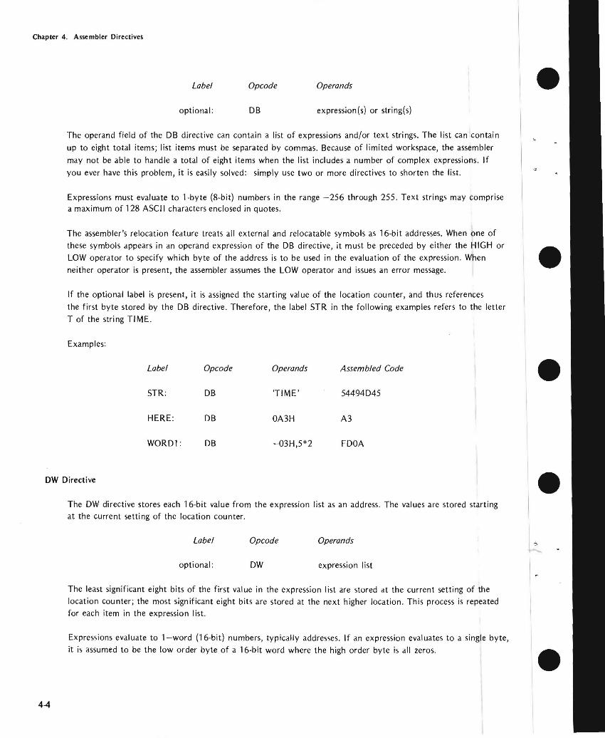
Chapter 4 Assembler Directives
Label Opcode Operands bulloptional DB expression(s) or string(s)
The operand field of the DB directive can contain a list of expressions andor text strings The list can contain up to eight total items list items must be separated by commas Because of limited workspace the assembler may not be able to handle a total of eight items when the list includes a number of complex expressions If
you ever have this problem it is easily solved simply use two or more directives to shorten the list
Expressions must evaluate to 1-byte (8-bit) numbers in the range -256 through 255 Text strings may comprise a maximum of 128 ASCII characters enclosed in quotes
The assemblers relocation feature treats all external and relocatable symbols as 16-bit addresses When one of these symbols appears in an operand expression of the DB directive it must be preceded by either the HIGH or LOW operator to specify which byte of the address is to be used in the evaluation of the expression When neither operator is present the assembler assumes the LOW operator and issues an error message bull If the optional label is present it is assigned the starting val ue of the location counter and thus references the first byte stored by the DB directive Therefore the label STR in the following examples refers to the letter T of the string TIME
Examples
Label Opcode Operands Assembled Code
STR DB TIME 54494045 bull HERE DB OA3H A3
WOR01 DB -03H52 FOOA
OW Directive
The OW directive stores each 16-bit value from the expression list as an address The values are stored starting bullat the current setting of the location counter
Label Opcode Operands I
optional OW expression list I The least significant eight bits of the first value in the expression list are stored at the current setting of the location counter the most significant eight bits are stored at the next higher location This process is repeated for each item in the expression list
Expressions evaluate to 1-word (16-bit) numbers typically addresses If an expression evaluates to a single byte it is assumed to be the low order byte of a 16middotbit word where the high order byte is all zeros bull
44
Chapter 4 Assembler Directives
bull
bull
bull
bull
List items must be separated by commas The list can contain up to eight total items Because of limited workshyspace the assembler may not be able to handle eight complex expressions If you ever have this problem simply use two or more DW directives to shorten the list
The reversed order for storing the high and low order bytes is the typical format for addresses stored in memory Thus the OW directive is commonly used for storing address constants
Strings containing one or two ASCII characters enclosed in quotation marks l1)ay also appear in the expression
list When using such strings in your program remember that the characters are stored in reversed order
Specifying a string longer than two characters causes an error
If the optional label is present it is middotdssigned the starting address of the location counter and thus references the first byte stored by the OW directive (This is the low order byte of the first item in the expression list)
Examples
Assume that COMP and FILL are labels defined elsewhere in the program COMP addresses memory location 3B1CH FILL addresses memory location 3EB4H
Label Opcode Operands Assembled Code
AOOR1 OW COMP 1C3B
AOOR2 OW FILL B43E
STRNG DW AAB 41004241
FOUR OW 4H 0400
MEMORY RESERVATION
DS Directive
The DS directive can be used to define a block of storage
Label Opcode Operand
optional DS expression
The value of expression specifies the number of bytes to be reserved for data storage In theory this value may
range from OOH through OFFFFH in practice you will reserve no more stordge than will fit in your available memory and still leave room for the program
Any symbol appearing in the operand expression must be defined before the assembler reaches the DS directive
bull Unlike the DB dnd OW directives OS assembles no data into your program The contents of the reserved storage are unpredictable when program execution is initiated
4-5
Chapter 4 Assembler Directives
If the optional label is present it is assigned the current value of the location counter and thus references the first byte of the reserved memory block bullIf the value of the operand expression is zero no memory is reserved However if the optional label is present it is assigned the current value of the location counter
The OS directive reserves memory by incrementing the location counter by the value of the operand expression
Example
TTYBUF OS 72 RESERVE 72 BYTES FOR A TERMINAL OUTPUT BUFFER
Programming Tips Data Description and Access
Random Access Versus Read Only Memory
When coding data descriptions keep in mind the mix of ROM and RAM in your application
Generally the DB and OW directives define constants items that can be assigned to ROM You can use these items in your program but you cannot modify them If these items are assigned to RAM they have an initial value that your program can modify during execution Notice however that these initial values must be reloaded into memory prior to each execution of the program
Variable data in memory must be assigned to RAM
Data Description
Before coding your program you must have a thorough understanding of its input and output data But youll probably find it more convenient to postpone coding the data descriptions until the remainder of the program is fairly well developed This way you will have a better idea of the constants and workareas needed in your program Also the organization of a typical program places instructions in lower memory followed by the data followed by the stack
Data Access
Accessing data from memory is typically a two-step process First you tell the processor where to find the data then the processor fetches the data from memory and loads it into a register usually the accumulator Therefore the following code sequences have the identical effect of loading the ASCII character A into the accumulator
AAA DB A ALPHA DB ABC
bull
bull
bull
LXI BAAA LXI BALPHA LDAX B LDAX B bull
4-6
Chapter 4 Assembler Directives
In the the LXI instructions load the address of the desired data into the Band C registers The LDAX
instructions then load the accumulator with one byte of data from the address specified in the Band C
The assernbler neither knows nor cares that only one character from the threemiddotcharacter field ALPHA has been
accessed The program must account for the characters at ALPHA+j and ALPHA+2 as in the following coding
sequence
ALPHA DB ABC FINE ALPHA
LXI BALPHA ADDRESS OF ALPHA shy
LDAX B I ST ALPHA CHAR
INX B B TO ALPHA+j
LDAX B 2ND ALPHA CHAR
INX B B TO ALPHA+2 LDAX B 3RD ALPHA CHAR
The coding above is acceptable for short data fields like ALPHA For you can conserve memory
by setting up an instruction sequence that is executed until the source data is exhausted
Add Symbols for Data Access
The following example was nrcgtccgttgt earlier as an illustration of the DS directive
Label Opcode Comment
TTYBUF DS 72 TTY BUFFER
To access data in this buffer such as TTYBUF +1 TTYBUF+72 can be a laborious and confusing when you want only selected fields from the buffer You can simplify
this task by subdividing the buffer with the directive
Label Opcode Comment
TTYBUF DS 72 RVE TTY BUFFER
10 EQU TTYBUF RECORD IDENTIFIER
- NAME EQU TTYBUF+6 20middotCHAR NAME FIELD
NUMBER EQU TTYBUF+26 lOmiddotCHAR EMPLOYEE NUMBER
DEPT EQU TTYBUF+36 DEPARTMENT NUMBER
SSNO EQU TTYBUF+41 SEC NUMBER
DOH EQU TTYBUF+50 OF HIRE
DESC EQU TTYBUF+56 DESCRIPTION
4middot7
Chapter 4 Assembler Directives
Subdividing data as shown in the example simplifies data access and provides useful documentation throughout your program Notice that these EQU directives can be inserted anywhere within the program as you need them but coding them as shown in the example provides a more useful record description
CONDITIONAL ASSEMBLY
The I F ELSE and ENDIF directives enable you to assemble portions of your program conditionally that is only if certain conditions that you specify are satisfied
Conditional assembly is especially useful when your application requires custom programs for a number of comshy
mon options As an example assume that a basic control program requires customizing to accept input from one of six different sensing devices and to drive one of five different control devices Rather than code some thirty separate programs to account for all the possibilities you can code a single program The code for the inshydividual sensors and drivers must be enclosed by the conditional directives When you need to generate a custom program you can insert SET directives near the beginning of the source program to select the desired sensor and driver routines
IF ELSE ENDIF Directives
Because these directives arc used in conjunction they are described together here
Label Opcode Operand
optional IF expression
optional ELSE
optional ENDIF
The assembler evaluates the expression in the operand field of the IF directive If bit 0 of the resulting value is
one (TRUE ) all instructions between the IF directive and the next ELSE or ENDIF directive are assembled When bit 0 is zero (FALSE) these instructions are ignored (A TRUE expression evaluates to OFFFFH and FALSE to OH only bit zero need be tested)
All statements included between an IF directive and its required associated ENDIF directive are defined as an IF-ENDIF block The ELSE directive is optional and only one ELSE directive may appear in an IF-ENDIF block When included ELSE is the converse of IF When bit 0 of the expression in the IF directive is zero all statements between ELSE and the next ENDIF are assembled If bit 0 is one these statements are ignored
Operands are not allowed with the ELSE and ENDIF directives
An IF-EN D I F block may appear within another IF-END I F block These blocks can be nested to eight levels
Macro definitions (explained in the next chapter) may appear within an IF-ENDIF block Conversely IF-ENDIF blocks may appear within macro definitions In either case you must be certain to terminate the macro definition
bull
bull
bull
bull
bull 4-8
Chapter 4 Assembler Directives
bull or IF-ENDIF block so that it can be assembled completely For when a macro definition begins in an IF block but terminates after an ELSE only a portion of the macro can be assembled Similarly an
IF-ENDIF block within a macro definition must terminate within that same macro definition
NOTE
Caution is vhen symbols are defined in IF-ENDIF blocks and referenced elsewhere within the program These
symbols are undefined when the evaluation of the IF ex-suppresses the of the IF-ENDIF block
Example 1 Simple IF-ENDIF Block
bull COND1 IF TYPE EO 0
IF TYPE = 0
15 TRUE
ENDIF
2 IF -ELSE-ENDI F Block
bull COND2 IF TYPE 0
MBLED IF TYPE == 0 TRUE
ELSE
ASSEMBLED IF TYPE == 0 FALSE
bull ENDIF
bull 4-9
Chapter 4 Assembler Directives
-I
Example 3 Nested IFs
COND3 IF TYPE EO 0 bull ASSEMBLED IF TYPE = 0
IS TRUE
IF MODE EO 1
LEVEL ASSEMBLED IF TYPE = 0 AND MODE = l ARE BOTH
TRUE ENDIF ELSE
LEVEL ASSEMBLED IF TYPE 0
2 IS FALSE bull IF MODE EO 2
ASSEMBLED IF TYPE = 0 IS FALSE AND MODE = 2 IS TRUE
LEVEL ELSE
ASSEMBLED IF TYPE = 0 AND MODE = 2 ARE BOTH bullFALSE
ENDIF ENDIF
ASSEMBLER TERMINATION
END Directive bullThe END directive identifies the end of the source program and terminates each pass of the assembler
Label Opcode Operand
optional END expression
Only one END statement may appear in a source program and it must be the last source statement
If the optional expression is present its value is used as the starting address for program execution If no exmiddot pression is given the assembler assumes zero as the starting address
When a number of separate program modules are to be joined together only one may specify a program starting address The module with a starting address is the main module When source files are combined using the INshy
CLUDE control there are no restrictions on which source file contains the END bull 4-10
Chapter 4 Assembler Directives
bull END-OF-TAPE INDICATION
The EOT directive allows you to specify the physical end of paper tape to simplify assembly of multiple-tape source
programs
EOT Directive
Label Opcode Operand
optional EOT
When EOT is recognized by the assembler the message NEXT TAPE is sent to the console and the assembler pauses
After the next tape is loaded a space bar character rece ived at the console signals continuation of the assembly
bull Data in the operand field causes an error
LOCATION COUNTER CONTROL AND RELOCATION
All the directives discussed in the remainder of this chapter relate directly to program relocation except for the
ASEG and ORG directives These directives are described first for the convenience of readers who do not use the
relocation feature
bull Location Counter Control (Non-Relocatable Mode)
When you elect not to use the relocation feature an assembler default generates an ASEG directive for you The
ASEG directive specifies that the program is to be assembled in the non-relocatable mode and establishes a
location cou nter for the assembly
bull The location counter performs the same function for the assembler as the program counter performs during
execution It tells the assembler the next memory location available for instruction or data assembly
Initially the location counter is set to zero The location counter can be altered by the ORG (origin) directive
ORG Directive
The ORG directive sets the location counter to the value specified by the operand expression
Label Opcode Operand
optional ORG expression
The location counter is set to the value of the operand expression Assembly-time evaluation of ORG expressions
bull always yields a modulo 64K address Thus the expression always yields an address in the range 0 through
65535 Any symbol in the expression must be previously defined The next machine instruction or data item is
assembled at the specified address
4-11
Chapter 4 Assembler Directives
If no ORG directive is included before the first instruction or data byte in your program assembly begins at location zero
Your program can include any number of ORG directives Multiple ORGs need not specify addresses in ascending sequence but if you fail to do so you may instruct the assembler to write over some previously assembled portion of the program
If the optional label is present it is assigned the current value of the location counter before it is updated by the ORG directive
Example
Assume that the current value of the location counter is OFH (decimal 15) when the following ORG directive is encountered
PAG1 ORG OFFH ORG ASSEMBLER TO LOCATION
OFFH (decimal 225)
The symbol PAGI is assigned the address OFH The next instruction or data byte is assembled at location OFFH
Introduction to Relocatability
A major feature of this assembler is its system for creating relocatable object code modules Support for this new
feature includes a number of new directives for the assembler and three new programs included in ISIS-II The three new programs - LIB LINK and LOCATE _ arc described in the ISIS-Ii System Users Guide The new
assembler directives are described later in this chapter
Relocatability allows the programmer to code programs or sections of programs without worrying about the final arrangement of the object code in memory This offers developers of microcomputer systems major adshyvantages in two areas memory management and modular program development
Memory Management
When developing testing and debugging a system on your Intellec microcomputer development system your only concern with locating a program is that it doesnt overlap the resident routines of ISIS-II Because the Intellec system has 32K 48K or 64K of random access memory the location of your future program is not a great concern_ However the program you arc developing will almost certainly use some mix of random access memory (RAM) readmiddotonly memory (ROM) andor programmable read-only memory (PROM) Therefore the location of your program affects both cost dnd performance in your application The relocatability feature allows
you to develop test and debug your program on the Intellec development system and then simply relocate the object code to suit your application
The relocatability feature also has a major advantage at assembly-time often large programs with many symbols cannot be assembled because of limited work space for the symbol table Such a program can be divided into a
number of modules that can be assembled separately and then linked together to form a single object program
bull
bull
bull
bull
bull 4-12
Chapter 4 Assembler Directives
Modular Program Development
Although relocatability may seem to be a formidable term what it really means is that you can subdivide a
complex program into a number of smaller simpler programs This concept is best illustrated through the use of an example Assume thai a microcomputer program is to control the spark advance on an automobile engine This requires the program to sample the ambient air temperature engine air intake temperature coolant temperashyture manifold vacuum idle sensor and throttle sensor
Let us examine the approaches two different programmers might take to solve this problem Both programmers
want to calculate the degree of spark advance or retardation that provides the best fuel economy with the lowest
emissions Programmer A codes a single program that senses all inputs and calculates the correct spark advance
Programmer B uses a modular approach and codes separate programs for each input plus one program to calculate
spark advance
Although Programmer A avoids the need to learn to use the relocatability feature the modular approach used by Programmer B has a number of advantages you should consider
bull Simplified Program Development
It is generally easier to code test and debug several simple programs than one complex program
bull Sharing the Programming Task
If Programmer B finds that he is falling behind schedule he can assign one or more of his subshy
programs to another programmer Because of his single program concept Programmer A will
probably have to complete the program himself
bull Ease of Testing
Programmer B can lest and debug most of his modules as soon as they arc assembled Programmer
A must lest his program as a whol~ Notice that Programmer B has an extra advantage if the
sensors are being developed at the same lime as the program If one oflhe sensors is behind
schedule Programmer B can continue developing and testing programs for the sensors that arc
ready Because Programmer A cannot test his program until all the sensors are developed his
testing schedule is dependent on events beyond his control
bull Programming Changes
Given the nature of automotive design it is reasonable to expect some changes Juring system development If a change to one of the sensors requires a programming change Programmer A must search through his entire program to find and alter the coding for that sensor Then he must retest the entire program to be certain that those changes do not affect any of the other sensors
By contrast Programmer B need be concerned only with the module for that one sensor This
advantage continues throughout the life of the program
4middot13
Chapter 4 Assembler Directives
DIRECTIVES USED FOR RELOCATION
Several directives have been added to the assembler to support the relocation feature These fdll into the general
categories of location counter control and program linkage
Location Counter Control (Relocatable Programs)
Relocatable programs or program modules may use three locdtion counters The ASEG DSEG and CSEG
directive~ specify which location counter is to be used
The ASEG directive specifies dn dbsolute code segment Even in a relocdtable program module you may want to assign certain code segments to specific addresses For example restart routines invoked by the RST instrucshytion require specific addresses
The CSEG directive specifies a relocatable code segment In general the CSEG location counter is used for porshytions of the program that are to be in some form of read-only memory such as mdchine instructions and proshygram constants
The DSEG location counter specifies a relocdtdble data segment This location counter is used for program
elements that must be located in random access memory
These directives allow you to control program segmentation at assembly time The LOCATE program described in the ISIS-II System Users Guide gives you control over program segment location Therefore the guidelines given dbove are only generdl since they can be overridden by the LOCATE program
Regardless of how many times the ASEG CSEG and DSEG directives appear in your program the assembler produces a single contiguous module Th is module comprises four segments code data stack and memory The LINK and LOCATE programs are used to combine segments from individual modules and relocate them in
memory These programs are explained in the ISIS-II System Users Guide
ASEG Directive
ASEG directs the assembler to use the location counter for the dbsolute program segment
Label Opcode Operand
optional ASEG
Operands are not permitted with the ASEG directive
All instructions and data following the ASEG directive are dssembled in the absolute mode The ASEG directive
remains in effect until d CSEG or DSEG directive is encountered
The ASEG location counter has an initial value of zero The ORG directive can be used to dssign a new value to the ASEG location counter
bull
bull
bull
bull
bull 4-14
Chapter 4 Assembler Directives
When begins the assembler assurres the ASEG directive to be in effect Therefore a CSEG or DSEG
must the first instruction or data definition in a relocatable module If neither of these directives
appears in the program the entire program is assembltd in absolute mode and can be executed immediately
after without using the LINK or LOCATE programs
CSEG Directive
CSEG directs the assembler to assemble instructions and data in the relocatable mode the code
segment location counter
Label Opcode Operand
blank optional CSEG PAGE
INPAGE
When a program contains multiple CSEG all CSEG directives the program must specify
The operand of a CSEG directive has no effect on the current assembly but is stored with code to be to the LINK and LOCATE programs programs are described in the ISIS-II
The LOCATE program uses this information to determine relocation boundaries when it
joins this code segment to code segments from other programs The of the operand is as follows
bull blank This code segment may be relocated to the next available byte boundary
bull PAGE This code segment must when relocated boundaries
occur in multiples of 256 512 etc)
INPAGE -- This code segment must fit within a single page when relocated
The CSEG directive remains in effect until an ASEG or DSEG directive is encountered_
The code segment location counter has an initial value of zero The ORG directive can be used to a new
val ue to the CSEG location counter
DSEG Directive
DSEG directs the assembler to assemble subsequent instructions and data in the relocatable mode using the data
segment location counter
Label Operand
blank DSEG PAGE
INPAGE
When multiple DSEG directives appear in a program they must all specify the same throughout the
program The operands for the DSEG directive have the same meaning as for the CSEG directive except that
they apply to the data segment
4-15
Chapter 4 Assembler Directives
There is no interaction between the operands specified for the DSEG and CSEG directives Thus a code segment
can be byte relocatable while the data segment is page relocatable bull The DSEG directive remaim in effect IJntil an ASEG or CSEG directive is encountered
The data segment location counter has an initial value of zero The ORG directive can be used to assign a new
value to the DSEG location counter
ORG Directive (Relocalable Mode)
The ORG directive can be used to alter the value of the location counter presently in use
Label Opcode Operand
optional ORG expression bullThere are three location counters but only one location counter is in use at any given point in the program
Which one depends on whether the ASEG CSEG or DSEG directive is in effect
Any symbol used in the operand expression must have been previously defined An exception causes phase
errors for all labels that follow the ORG and a label error if the undefined error is defined later
When the ORG directive appears in a relocatable program segment the value of its operand expression must be
either absolute or relocatable within the current segment Thus if the ORG directive appears within a data segshy
ment the value of its expression must be relocatable within the data segment An error occurs if the expression bullevaluates to an address in the code segment
If the optional label is present it is assigned the current value of the location counter presently in use before
the ORG directive is executed
Program Linkage Directives
Modular programming and the relocation feature enable you to assemble and test a number of separate programs bullthat are to be joined together and executed as a single program Eventually it becomes necessary for these
separate programs to communicate information among themselves Establishing such communication is the
fu net ion of the program I inkage directives
A program may share its data addresses and instruction addresses with other programs Only items having an
entry in the symbol table can be shared with other programs therefore the item must be assigned a name or a
label when it is defined in the program I tems to be shared with other programs must be declared in a PUBLIC directive
Your program can directly access data or instructions defined in another program if you know the actual
address of the item but this is unlikely when both programs use relocation Your program can also gain access
to data or instructions declared as PUBLIC in other programs Notice however that the assembler normally
4-16
Chapter 4 Assembler Directives
flags as an error ltlny reference to ltl nltlme or lltlbel thltlt hltlS not been defined in your program To ltlvoid this
you must provide the assembler with ltl list of items used in your program but defined in some other program
These items must be declltlred in an EXTRN directive
The two remaining program linkage directives NAME and STKLN are individually explained later in this chltlpter
PUBLIC Directive
The PUBLIC directive makes each of the symbols listed in the operand field available for access by other programs
Label Opcode Operands
optionltll PUBLIC name-list
Each item in the operand name-list must be the name or label assigned to data or an instruction elsewhere in this program When multiple names appear in the list they must be seplttrated by commas Each nltlme may be declared PUBLIC only once in a program module Reserved words and externltll symbols (see the EXTRN directive below) cannot be declared to be PUBLIC symbols
PUBLIC directives may appear anywhere within a program module
if an item in the operand name-list has no corresponding entry in the symbol table (implying that it is undeshy
fined) it is flagged as an error
Example
PUBLIC SINCOSTANSQRT
EXTRN Directive
The EXTRN directive provides the assembler with a list of symbols referenced in this program but defined in a
different program Because of this the assembler establishes linkage to the other program and does not flag the
undefi ned references as errors
Label Opcode Operands
optional EXTRN name-list
Each item in the name-list identifies a symbol that may be referenced in this program but is defined in another program When multiple items appear in the list they must be separated by commas
If a symbol in the operand name-list is also defined in this program by the user or is a reserved symbol the effect
is the same as defining the same symbol more than once in a program The assembler flags this error
EXTRN directives may appear anywhere within a program module
A symbol may be declared to be external only once in a program module Symbols declared to be PUBLIC cannot also be declared to be EXTRN symbols
4-17
Chapter 4 Assembler Directives
If you omit a symbol from the name--list but reference it in the program the symbol is undefined The assembler
flags this error You may include symbols in the operand name--list that are not referenced in the program withshy bullout causing an error
Example
EXTRN ENTRYADDRTNBEGIN
NAME Directive
The NAME directive assigns a name to the object module generated by this assembly
Label Opcode Operand
optional NAME module-name bull The NAME directive requires the presence of a module-name in the operand field This name must conform to
the rules for defining symbols
Module names are necessary so that you can refer to a module and specify the proper sequence of modules
when a number of modules are to be bound together
The NAME directive must precede the first data or instruction coding in the source program but may follow
comments and control lines bullIf the NAME directive is missing from the program the assembler supplies a default NAME directive with the module-name MODULE This will cause an error if you attempt to bind together several object program modules and more than one has the name MODULE Also if you make an error coding the NAME directive the default name MODULE is assigned
The module - name assigned by the NAME directive appears as part of the page heading in the assembly listing
Example bullNAME MAIN
STKLN Directive
Regardless of the number of object program modules you may bind together only one stack is generated The
STKLN directive allows you to specify the number of bytes to be reserved for the stack for each module
Label Opcode Operand
optional STKLN expression
The operand expression must evaluate to a number which will be used as the maximum size of the stack bull 4middot18
Chapter 4 Assembler Directives
bull When the STKLN directive is omitted the provides a default STKLN of zero This is useful when multiple programs are bound only one stack will be so only one program module need
the stack size However you should provide a STKLN if your module is to be tested separately and uses the stack
If your program includes more than one STKLN directive the last value is retained
STKLN 100
STACI( and MEMORY Reserved Words
bull The reserved words STACK and MEMORY are not directives but are of interest to programmers using the relocation feature These reserved words are external references whose addresses are supplied by the LOCATE
program
STACK is the reference to the stack address You need this address to initialize the stack
pointer register Also you can base data structures on th is address symbolic references such as 5T ACK+1
etc
bull MEMORY is the symbolic reference to the first byte of unused memory the end of your program you can base data structures on this address symbolic such as MEMORY MEMORY+I etc
Programming Testing Rclocatable Modules
The ability to test individual program modules is a major of modular programming However many program modules are not self-sufficient and require some modification before they can be tested The following is a discussion of some of the more Common modifications that may be required
bull Initialization Routines
In most complete programs a number of or initialization are performed when execution first begins If the program module you are relies on initialization assigned to a different
you must duplicate those procedures in the module to be tested however that you can link any number of modules together for
One of the most important initialization is to set the stack The LOCATE program determines the origin of the stack
Your program should include the instruction to initialize the stack
LXI
bull 4middot19
Chapler 4 Assembler Direclives
InputOutput
When testing program modules it is likely that some input or output procedures appear in other modules Your bull program must simulate any of these procedures it needs to operate Since your Intellec development system
probably has considerably more random access memory than you need to test a program module you may be
able to simulate input and output data right in memory The LOCATE program supplies an address for the
reserved word MEMORY this is the address of the first byte of unused memory past the end of your program
You can access this memory using the symbolic reference MEMORY MEMORY+l and so on This memory can be used for storing test data or even for a program that generates test data
Remove Coding Used for Testing
After testing your program be certain to remove any code you inserted for testing In particular make certain that only one module in the complete program initializes the stack pointer bull
bull
bull
bull 4-20
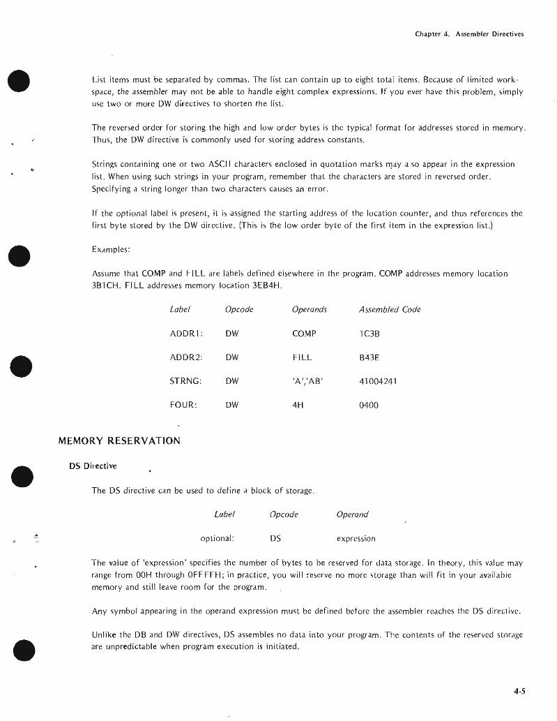
Chapter 4 Assembler Directives
bull
bull
bull
bull
List items must be separated by commas The list can contain up to eight total items Because of limited workshyspace the assembler may not be able to handle eight complex expressions If you ever have this problem simply use two or more DW directives to shorten the list
The reversed order for storing the high and low order bytes is the typical format for addresses stored in memory Thus the OW directive is commonly used for storing address constants
Strings containing one or two ASCII characters enclosed in quotation marks l1)ay also appear in the expression
list When using such strings in your program remember that the characters are stored in reversed order
Specifying a string longer than two characters causes an error
If the optional label is present it is middotdssigned the starting address of the location counter and thus references the first byte stored by the OW directive (This is the low order byte of the first item in the expression list)
Examples
Assume that COMP and FILL are labels defined elsewhere in the program COMP addresses memory location 3B1CH FILL addresses memory location 3EB4H
Label Opcode Operands Assembled Code
AOOR1 OW COMP 1C3B
AOOR2 OW FILL B43E
STRNG DW AAB 41004241
FOUR OW 4H 0400
MEMORY RESERVATION
DS Directive
The DS directive can be used to define a block of storage
Label Opcode Operand
optional DS expression
The value of expression specifies the number of bytes to be reserved for data storage In theory this value may
range from OOH through OFFFFH in practice you will reserve no more stordge than will fit in your available memory and still leave room for the program
Any symbol appearing in the operand expression must be defined before the assembler reaches the DS directive
bull Unlike the DB dnd OW directives OS assembles no data into your program The contents of the reserved storage are unpredictable when program execution is initiated
4-5
Chapter 4 Assembler Directives
If the optional label is present it is assigned the current value of the location counter and thus references the first byte of the reserved memory block bullIf the value of the operand expression is zero no memory is reserved However if the optional label is present it is assigned the current value of the location counter
The OS directive reserves memory by incrementing the location counter by the value of the operand expression
Example
TTYBUF OS 72 RESERVE 72 BYTES FOR A TERMINAL OUTPUT BUFFER
Programming Tips Data Description and Access
Random Access Versus Read Only Memory
When coding data descriptions keep in mind the mix of ROM and RAM in your application
Generally the DB and OW directives define constants items that can be assigned to ROM You can use these items in your program but you cannot modify them If these items are assigned to RAM they have an initial value that your program can modify during execution Notice however that these initial values must be reloaded into memory prior to each execution of the program
Variable data in memory must be assigned to RAM
Data Description
Before coding your program you must have a thorough understanding of its input and output data But youll probably find it more convenient to postpone coding the data descriptions until the remainder of the program is fairly well developed This way you will have a better idea of the constants and workareas needed in your program Also the organization of a typical program places instructions in lower memory followed by the data followed by the stack
Data Access
Accessing data from memory is typically a two-step process First you tell the processor where to find the data then the processor fetches the data from memory and loads it into a register usually the accumulator Therefore the following code sequences have the identical effect of loading the ASCII character A into the accumulator
AAA DB A ALPHA DB ABC
bull
bull
bull
LXI BAAA LXI BALPHA LDAX B LDAX B bull
4-6
Chapter 4 Assembler Directives
In the the LXI instructions load the address of the desired data into the Band C registers The LDAX
instructions then load the accumulator with one byte of data from the address specified in the Band C
The assernbler neither knows nor cares that only one character from the threemiddotcharacter field ALPHA has been
accessed The program must account for the characters at ALPHA+j and ALPHA+2 as in the following coding
sequence
ALPHA DB ABC FINE ALPHA
LXI BALPHA ADDRESS OF ALPHA shy
LDAX B I ST ALPHA CHAR
INX B B TO ALPHA+j
LDAX B 2ND ALPHA CHAR
INX B B TO ALPHA+2 LDAX B 3RD ALPHA CHAR
The coding above is acceptable for short data fields like ALPHA For you can conserve memory
by setting up an instruction sequence that is executed until the source data is exhausted
Add Symbols for Data Access
The following example was nrcgtccgttgt earlier as an illustration of the DS directive
Label Opcode Comment
TTYBUF DS 72 TTY BUFFER
To access data in this buffer such as TTYBUF +1 TTYBUF+72 can be a laborious and confusing when you want only selected fields from the buffer You can simplify
this task by subdividing the buffer with the directive
Label Opcode Comment
TTYBUF DS 72 RVE TTY BUFFER
10 EQU TTYBUF RECORD IDENTIFIER
- NAME EQU TTYBUF+6 20middotCHAR NAME FIELD
NUMBER EQU TTYBUF+26 lOmiddotCHAR EMPLOYEE NUMBER
DEPT EQU TTYBUF+36 DEPARTMENT NUMBER
SSNO EQU TTYBUF+41 SEC NUMBER
DOH EQU TTYBUF+50 OF HIRE
DESC EQU TTYBUF+56 DESCRIPTION
4middot7
Chapter 4 Assembler Directives
Subdividing data as shown in the example simplifies data access and provides useful documentation throughout your program Notice that these EQU directives can be inserted anywhere within the program as you need them but coding them as shown in the example provides a more useful record description
CONDITIONAL ASSEMBLY
The I F ELSE and ENDIF directives enable you to assemble portions of your program conditionally that is only if certain conditions that you specify are satisfied
Conditional assembly is especially useful when your application requires custom programs for a number of comshy
mon options As an example assume that a basic control program requires customizing to accept input from one of six different sensing devices and to drive one of five different control devices Rather than code some thirty separate programs to account for all the possibilities you can code a single program The code for the inshydividual sensors and drivers must be enclosed by the conditional directives When you need to generate a custom program you can insert SET directives near the beginning of the source program to select the desired sensor and driver routines
IF ELSE ENDIF Directives
Because these directives arc used in conjunction they are described together here
Label Opcode Operand
optional IF expression
optional ELSE
optional ENDIF
The assembler evaluates the expression in the operand field of the IF directive If bit 0 of the resulting value is
one (TRUE ) all instructions between the IF directive and the next ELSE or ENDIF directive are assembled When bit 0 is zero (FALSE) these instructions are ignored (A TRUE expression evaluates to OFFFFH and FALSE to OH only bit zero need be tested)
All statements included between an IF directive and its required associated ENDIF directive are defined as an IF-ENDIF block The ELSE directive is optional and only one ELSE directive may appear in an IF-ENDIF block When included ELSE is the converse of IF When bit 0 of the expression in the IF directive is zero all statements between ELSE and the next ENDIF are assembled If bit 0 is one these statements are ignored
Operands are not allowed with the ELSE and ENDIF directives
An IF-EN D I F block may appear within another IF-END I F block These blocks can be nested to eight levels
Macro definitions (explained in the next chapter) may appear within an IF-ENDIF block Conversely IF-ENDIF blocks may appear within macro definitions In either case you must be certain to terminate the macro definition
bull
bull
bull
bull
bull 4-8
Chapter 4 Assembler Directives
bull or IF-ENDIF block so that it can be assembled completely For when a macro definition begins in an IF block but terminates after an ELSE only a portion of the macro can be assembled Similarly an
IF-ENDIF block within a macro definition must terminate within that same macro definition
NOTE
Caution is vhen symbols are defined in IF-ENDIF blocks and referenced elsewhere within the program These
symbols are undefined when the evaluation of the IF ex-suppresses the of the IF-ENDIF block
Example 1 Simple IF-ENDIF Block
bull COND1 IF TYPE EO 0
IF TYPE = 0
15 TRUE
ENDIF
2 IF -ELSE-ENDI F Block
bull COND2 IF TYPE 0
MBLED IF TYPE == 0 TRUE
ELSE
ASSEMBLED IF TYPE == 0 FALSE
bull ENDIF
bull 4-9
Chapter 4 Assembler Directives
-I
Example 3 Nested IFs
COND3 IF TYPE EO 0 bull ASSEMBLED IF TYPE = 0
IS TRUE
IF MODE EO 1
LEVEL ASSEMBLED IF TYPE = 0 AND MODE = l ARE BOTH
TRUE ENDIF ELSE
LEVEL ASSEMBLED IF TYPE 0
2 IS FALSE bull IF MODE EO 2
ASSEMBLED IF TYPE = 0 IS FALSE AND MODE = 2 IS TRUE
LEVEL ELSE
ASSEMBLED IF TYPE = 0 AND MODE = 2 ARE BOTH bullFALSE
ENDIF ENDIF
ASSEMBLER TERMINATION
END Directive bullThe END directive identifies the end of the source program and terminates each pass of the assembler
Label Opcode Operand
optional END expression
Only one END statement may appear in a source program and it must be the last source statement
If the optional expression is present its value is used as the starting address for program execution If no exmiddot pression is given the assembler assumes zero as the starting address
When a number of separate program modules are to be joined together only one may specify a program starting address The module with a starting address is the main module When source files are combined using the INshy
CLUDE control there are no restrictions on which source file contains the END bull 4-10
Chapter 4 Assembler Directives
bull END-OF-TAPE INDICATION
The EOT directive allows you to specify the physical end of paper tape to simplify assembly of multiple-tape source
programs
EOT Directive
Label Opcode Operand
optional EOT
When EOT is recognized by the assembler the message NEXT TAPE is sent to the console and the assembler pauses
After the next tape is loaded a space bar character rece ived at the console signals continuation of the assembly
bull Data in the operand field causes an error
LOCATION COUNTER CONTROL AND RELOCATION
All the directives discussed in the remainder of this chapter relate directly to program relocation except for the
ASEG and ORG directives These directives are described first for the convenience of readers who do not use the
relocation feature
bull Location Counter Control (Non-Relocatable Mode)
When you elect not to use the relocation feature an assembler default generates an ASEG directive for you The
ASEG directive specifies that the program is to be assembled in the non-relocatable mode and establishes a
location cou nter for the assembly
bull The location counter performs the same function for the assembler as the program counter performs during
execution It tells the assembler the next memory location available for instruction or data assembly
Initially the location counter is set to zero The location counter can be altered by the ORG (origin) directive
ORG Directive
The ORG directive sets the location counter to the value specified by the operand expression
Label Opcode Operand
optional ORG expression
The location counter is set to the value of the operand expression Assembly-time evaluation of ORG expressions
bull always yields a modulo 64K address Thus the expression always yields an address in the range 0 through
65535 Any symbol in the expression must be previously defined The next machine instruction or data item is
assembled at the specified address
4-11
Chapter 4 Assembler Directives
If no ORG directive is included before the first instruction or data byte in your program assembly begins at location zero
Your program can include any number of ORG directives Multiple ORGs need not specify addresses in ascending sequence but if you fail to do so you may instruct the assembler to write over some previously assembled portion of the program
If the optional label is present it is assigned the current value of the location counter before it is updated by the ORG directive
Example
Assume that the current value of the location counter is OFH (decimal 15) when the following ORG directive is encountered
PAG1 ORG OFFH ORG ASSEMBLER TO LOCATION
OFFH (decimal 225)
The symbol PAGI is assigned the address OFH The next instruction or data byte is assembled at location OFFH
Introduction to Relocatability
A major feature of this assembler is its system for creating relocatable object code modules Support for this new
feature includes a number of new directives for the assembler and three new programs included in ISIS-II The three new programs - LIB LINK and LOCATE _ arc described in the ISIS-Ii System Users Guide The new
assembler directives are described later in this chapter
Relocatability allows the programmer to code programs or sections of programs without worrying about the final arrangement of the object code in memory This offers developers of microcomputer systems major adshyvantages in two areas memory management and modular program development
Memory Management
When developing testing and debugging a system on your Intellec microcomputer development system your only concern with locating a program is that it doesnt overlap the resident routines of ISIS-II Because the Intellec system has 32K 48K or 64K of random access memory the location of your future program is not a great concern_ However the program you arc developing will almost certainly use some mix of random access memory (RAM) readmiddotonly memory (ROM) andor programmable read-only memory (PROM) Therefore the location of your program affects both cost dnd performance in your application The relocatability feature allows
you to develop test and debug your program on the Intellec development system and then simply relocate the object code to suit your application
The relocatability feature also has a major advantage at assembly-time often large programs with many symbols cannot be assembled because of limited work space for the symbol table Such a program can be divided into a
number of modules that can be assembled separately and then linked together to form a single object program
bull
bull
bull
bull
bull 4-12
Chapter 4 Assembler Directives
Modular Program Development
Although relocatability may seem to be a formidable term what it really means is that you can subdivide a
complex program into a number of smaller simpler programs This concept is best illustrated through the use of an example Assume thai a microcomputer program is to control the spark advance on an automobile engine This requires the program to sample the ambient air temperature engine air intake temperature coolant temperashyture manifold vacuum idle sensor and throttle sensor
Let us examine the approaches two different programmers might take to solve this problem Both programmers
want to calculate the degree of spark advance or retardation that provides the best fuel economy with the lowest
emissions Programmer A codes a single program that senses all inputs and calculates the correct spark advance
Programmer B uses a modular approach and codes separate programs for each input plus one program to calculate
spark advance
Although Programmer A avoids the need to learn to use the relocatability feature the modular approach used by Programmer B has a number of advantages you should consider
bull Simplified Program Development
It is generally easier to code test and debug several simple programs than one complex program
bull Sharing the Programming Task
If Programmer B finds that he is falling behind schedule he can assign one or more of his subshy
programs to another programmer Because of his single program concept Programmer A will
probably have to complete the program himself
bull Ease of Testing
Programmer B can lest and debug most of his modules as soon as they arc assembled Programmer
A must lest his program as a whol~ Notice that Programmer B has an extra advantage if the
sensors are being developed at the same lime as the program If one oflhe sensors is behind
schedule Programmer B can continue developing and testing programs for the sensors that arc
ready Because Programmer A cannot test his program until all the sensors are developed his
testing schedule is dependent on events beyond his control
bull Programming Changes
Given the nature of automotive design it is reasonable to expect some changes Juring system development If a change to one of the sensors requires a programming change Programmer A must search through his entire program to find and alter the coding for that sensor Then he must retest the entire program to be certain that those changes do not affect any of the other sensors
By contrast Programmer B need be concerned only with the module for that one sensor This
advantage continues throughout the life of the program
4middot13
Chapter 4 Assembler Directives
DIRECTIVES USED FOR RELOCATION
Several directives have been added to the assembler to support the relocation feature These fdll into the general
categories of location counter control and program linkage
Location Counter Control (Relocatable Programs)
Relocatable programs or program modules may use three locdtion counters The ASEG DSEG and CSEG
directive~ specify which location counter is to be used
The ASEG directive specifies dn dbsolute code segment Even in a relocdtable program module you may want to assign certain code segments to specific addresses For example restart routines invoked by the RST instrucshytion require specific addresses
The CSEG directive specifies a relocatable code segment In general the CSEG location counter is used for porshytions of the program that are to be in some form of read-only memory such as mdchine instructions and proshygram constants
The DSEG location counter specifies a relocdtdble data segment This location counter is used for program
elements that must be located in random access memory
These directives allow you to control program segmentation at assembly time The LOCATE program described in the ISIS-II System Users Guide gives you control over program segment location Therefore the guidelines given dbove are only generdl since they can be overridden by the LOCATE program
Regardless of how many times the ASEG CSEG and DSEG directives appear in your program the assembler produces a single contiguous module Th is module comprises four segments code data stack and memory The LINK and LOCATE programs are used to combine segments from individual modules and relocate them in
memory These programs are explained in the ISIS-II System Users Guide
ASEG Directive
ASEG directs the assembler to use the location counter for the dbsolute program segment
Label Opcode Operand
optional ASEG
Operands are not permitted with the ASEG directive
All instructions and data following the ASEG directive are dssembled in the absolute mode The ASEG directive
remains in effect until d CSEG or DSEG directive is encountered
The ASEG location counter has an initial value of zero The ORG directive can be used to dssign a new value to the ASEG location counter
bull
bull
bull
bull
bull 4-14
Chapter 4 Assembler Directives
When begins the assembler assurres the ASEG directive to be in effect Therefore a CSEG or DSEG
must the first instruction or data definition in a relocatable module If neither of these directives
appears in the program the entire program is assembltd in absolute mode and can be executed immediately
after without using the LINK or LOCATE programs
CSEG Directive
CSEG directs the assembler to assemble instructions and data in the relocatable mode the code
segment location counter
Label Opcode Operand
blank optional CSEG PAGE
INPAGE
When a program contains multiple CSEG all CSEG directives the program must specify
The operand of a CSEG directive has no effect on the current assembly but is stored with code to be to the LINK and LOCATE programs programs are described in the ISIS-II
The LOCATE program uses this information to determine relocation boundaries when it
joins this code segment to code segments from other programs The of the operand is as follows
bull blank This code segment may be relocated to the next available byte boundary
bull PAGE This code segment must when relocated boundaries
occur in multiples of 256 512 etc)
INPAGE -- This code segment must fit within a single page when relocated
The CSEG directive remains in effect until an ASEG or DSEG directive is encountered_
The code segment location counter has an initial value of zero The ORG directive can be used to a new
val ue to the CSEG location counter
DSEG Directive
DSEG directs the assembler to assemble subsequent instructions and data in the relocatable mode using the data
segment location counter
Label Operand
blank DSEG PAGE
INPAGE
When multiple DSEG directives appear in a program they must all specify the same throughout the
program The operands for the DSEG directive have the same meaning as for the CSEG directive except that
they apply to the data segment
4-15
Chapter 4 Assembler Directives
There is no interaction between the operands specified for the DSEG and CSEG directives Thus a code segment
can be byte relocatable while the data segment is page relocatable bull The DSEG directive remaim in effect IJntil an ASEG or CSEG directive is encountered
The data segment location counter has an initial value of zero The ORG directive can be used to assign a new
value to the DSEG location counter
ORG Directive (Relocalable Mode)
The ORG directive can be used to alter the value of the location counter presently in use
Label Opcode Operand
optional ORG expression bullThere are three location counters but only one location counter is in use at any given point in the program
Which one depends on whether the ASEG CSEG or DSEG directive is in effect
Any symbol used in the operand expression must have been previously defined An exception causes phase
errors for all labels that follow the ORG and a label error if the undefined error is defined later
When the ORG directive appears in a relocatable program segment the value of its operand expression must be
either absolute or relocatable within the current segment Thus if the ORG directive appears within a data segshy
ment the value of its expression must be relocatable within the data segment An error occurs if the expression bullevaluates to an address in the code segment
If the optional label is present it is assigned the current value of the location counter presently in use before
the ORG directive is executed
Program Linkage Directives
Modular programming and the relocation feature enable you to assemble and test a number of separate programs bullthat are to be joined together and executed as a single program Eventually it becomes necessary for these
separate programs to communicate information among themselves Establishing such communication is the
fu net ion of the program I inkage directives
A program may share its data addresses and instruction addresses with other programs Only items having an
entry in the symbol table can be shared with other programs therefore the item must be assigned a name or a
label when it is defined in the program I tems to be shared with other programs must be declared in a PUBLIC directive
Your program can directly access data or instructions defined in another program if you know the actual
address of the item but this is unlikely when both programs use relocation Your program can also gain access
to data or instructions declared as PUBLIC in other programs Notice however that the assembler normally
4-16
Chapter 4 Assembler Directives
flags as an error ltlny reference to ltl nltlme or lltlbel thltlt hltlS not been defined in your program To ltlvoid this
you must provide the assembler with ltl list of items used in your program but defined in some other program
These items must be declltlred in an EXTRN directive
The two remaining program linkage directives NAME and STKLN are individually explained later in this chltlpter
PUBLIC Directive
The PUBLIC directive makes each of the symbols listed in the operand field available for access by other programs
Label Opcode Operands
optionltll PUBLIC name-list
Each item in the operand name-list must be the name or label assigned to data or an instruction elsewhere in this program When multiple names appear in the list they must be seplttrated by commas Each nltlme may be declared PUBLIC only once in a program module Reserved words and externltll symbols (see the EXTRN directive below) cannot be declared to be PUBLIC symbols
PUBLIC directives may appear anywhere within a program module
if an item in the operand name-list has no corresponding entry in the symbol table (implying that it is undeshy
fined) it is flagged as an error
Example
PUBLIC SINCOSTANSQRT
EXTRN Directive
The EXTRN directive provides the assembler with a list of symbols referenced in this program but defined in a
different program Because of this the assembler establishes linkage to the other program and does not flag the
undefi ned references as errors
Label Opcode Operands
optional EXTRN name-list
Each item in the name-list identifies a symbol that may be referenced in this program but is defined in another program When multiple items appear in the list they must be separated by commas
If a symbol in the operand name-list is also defined in this program by the user or is a reserved symbol the effect
is the same as defining the same symbol more than once in a program The assembler flags this error
EXTRN directives may appear anywhere within a program module
A symbol may be declared to be external only once in a program module Symbols declared to be PUBLIC cannot also be declared to be EXTRN symbols
4-17
Chapter 4 Assembler Directives
If you omit a symbol from the name--list but reference it in the program the symbol is undefined The assembler
flags this error You may include symbols in the operand name--list that are not referenced in the program withshy bullout causing an error
Example
EXTRN ENTRYADDRTNBEGIN
NAME Directive
The NAME directive assigns a name to the object module generated by this assembly
Label Opcode Operand
optional NAME module-name bull The NAME directive requires the presence of a module-name in the operand field This name must conform to
the rules for defining symbols
Module names are necessary so that you can refer to a module and specify the proper sequence of modules
when a number of modules are to be bound together
The NAME directive must precede the first data or instruction coding in the source program but may follow
comments and control lines bullIf the NAME directive is missing from the program the assembler supplies a default NAME directive with the module-name MODULE This will cause an error if you attempt to bind together several object program modules and more than one has the name MODULE Also if you make an error coding the NAME directive the default name MODULE is assigned
The module - name assigned by the NAME directive appears as part of the page heading in the assembly listing
Example bullNAME MAIN
STKLN Directive
Regardless of the number of object program modules you may bind together only one stack is generated The
STKLN directive allows you to specify the number of bytes to be reserved for the stack for each module
Label Opcode Operand
optional STKLN expression
The operand expression must evaluate to a number which will be used as the maximum size of the stack bull 4middot18
Chapter 4 Assembler Directives
bull When the STKLN directive is omitted the provides a default STKLN of zero This is useful when multiple programs are bound only one stack will be so only one program module need
the stack size However you should provide a STKLN if your module is to be tested separately and uses the stack
If your program includes more than one STKLN directive the last value is retained
STKLN 100
STACI( and MEMORY Reserved Words
bull The reserved words STACK and MEMORY are not directives but are of interest to programmers using the relocation feature These reserved words are external references whose addresses are supplied by the LOCATE
program
STACK is the reference to the stack address You need this address to initialize the stack
pointer register Also you can base data structures on th is address symbolic references such as 5T ACK+1
etc
bull MEMORY is the symbolic reference to the first byte of unused memory the end of your program you can base data structures on this address symbolic such as MEMORY MEMORY+I etc
Programming Testing Rclocatable Modules
The ability to test individual program modules is a major of modular programming However many program modules are not self-sufficient and require some modification before they can be tested The following is a discussion of some of the more Common modifications that may be required
bull Initialization Routines
In most complete programs a number of or initialization are performed when execution first begins If the program module you are relies on initialization assigned to a different
you must duplicate those procedures in the module to be tested however that you can link any number of modules together for
One of the most important initialization is to set the stack The LOCATE program determines the origin of the stack
Your program should include the instruction to initialize the stack
LXI
bull 4middot19
Chapler 4 Assembler Direclives
InputOutput
When testing program modules it is likely that some input or output procedures appear in other modules Your bull program must simulate any of these procedures it needs to operate Since your Intellec development system
probably has considerably more random access memory than you need to test a program module you may be
able to simulate input and output data right in memory The LOCATE program supplies an address for the
reserved word MEMORY this is the address of the first byte of unused memory past the end of your program
You can access this memory using the symbolic reference MEMORY MEMORY+l and so on This memory can be used for storing test data or even for a program that generates test data
Remove Coding Used for Testing
After testing your program be certain to remove any code you inserted for testing In particular make certain that only one module in the complete program initializes the stack pointer bull
bull
bull
bull 4-20
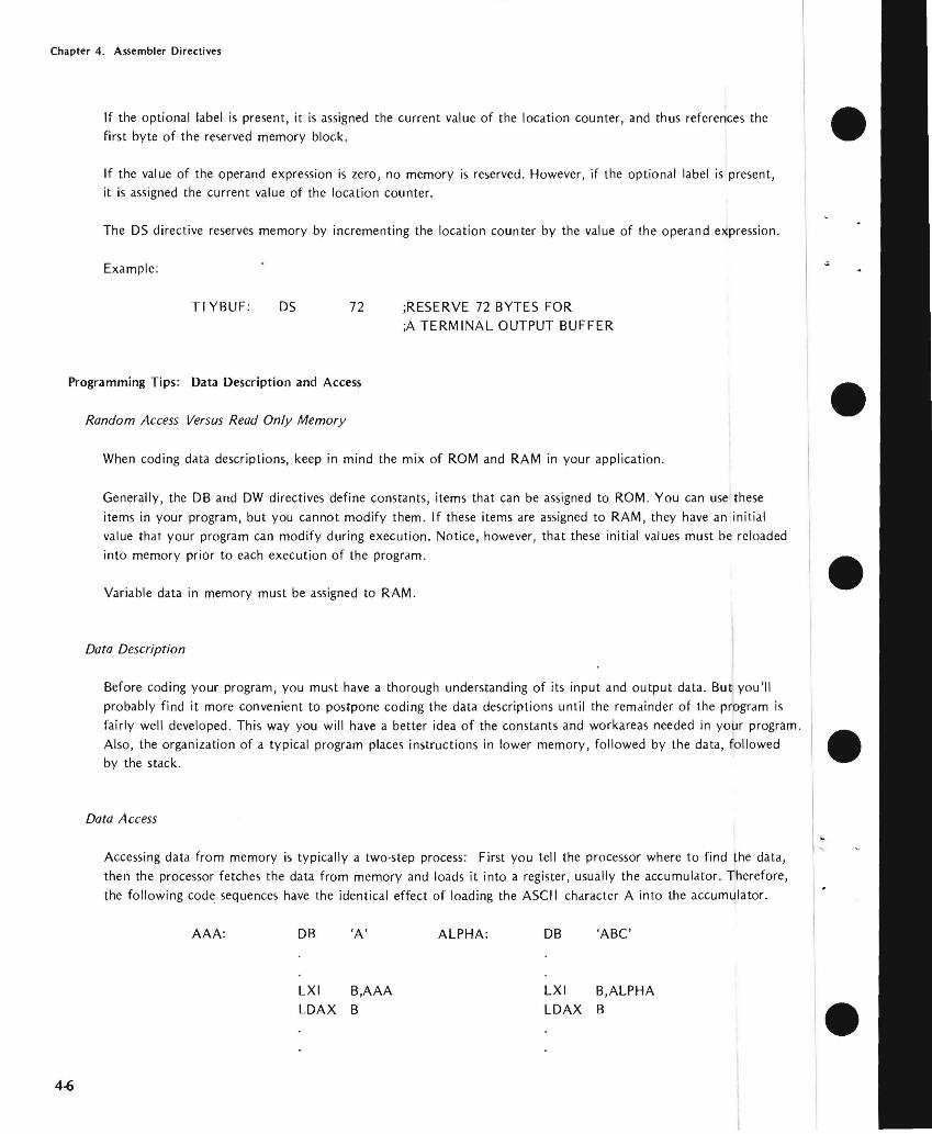
Chapter 4 Assembler Directives
If the optional label is present it is assigned the current value of the location counter and thus references the first byte of the reserved memory block bullIf the value of the operand expression is zero no memory is reserved However if the optional label is present it is assigned the current value of the location counter
The OS directive reserves memory by incrementing the location counter by the value of the operand expression
Example
TTYBUF OS 72 RESERVE 72 BYTES FOR A TERMINAL OUTPUT BUFFER
Programming Tips Data Description and Access
Random Access Versus Read Only Memory
When coding data descriptions keep in mind the mix of ROM and RAM in your application
Generally the DB and OW directives define constants items that can be assigned to ROM You can use these items in your program but you cannot modify them If these items are assigned to RAM they have an initial value that your program can modify during execution Notice however that these initial values must be reloaded into memory prior to each execution of the program
Variable data in memory must be assigned to RAM
Data Description
Before coding your program you must have a thorough understanding of its input and output data But youll probably find it more convenient to postpone coding the data descriptions until the remainder of the program is fairly well developed This way you will have a better idea of the constants and workareas needed in your program Also the organization of a typical program places instructions in lower memory followed by the data followed by the stack
Data Access
Accessing data from memory is typically a two-step process First you tell the processor where to find the data then the processor fetches the data from memory and loads it into a register usually the accumulator Therefore the following code sequences have the identical effect of loading the ASCII character A into the accumulator
AAA DB A ALPHA DB ABC
bull
bull
bull
LXI BAAA LXI BALPHA LDAX B LDAX B bull
4-6
Chapter 4 Assembler Directives
In the the LXI instructions load the address of the desired data into the Band C registers The LDAX
instructions then load the accumulator with one byte of data from the address specified in the Band C
The assernbler neither knows nor cares that only one character from the threemiddotcharacter field ALPHA has been
accessed The program must account for the characters at ALPHA+j and ALPHA+2 as in the following coding
sequence
ALPHA DB ABC FINE ALPHA
LXI BALPHA ADDRESS OF ALPHA shy
LDAX B I ST ALPHA CHAR
INX B B TO ALPHA+j
LDAX B 2ND ALPHA CHAR
INX B B TO ALPHA+2 LDAX B 3RD ALPHA CHAR
The coding above is acceptable for short data fields like ALPHA For you can conserve memory
by setting up an instruction sequence that is executed until the source data is exhausted
Add Symbols for Data Access
The following example was nrcgtccgttgt earlier as an illustration of the DS directive
Label Opcode Comment
TTYBUF DS 72 TTY BUFFER
To access data in this buffer such as TTYBUF +1 TTYBUF+72 can be a laborious and confusing when you want only selected fields from the buffer You can simplify
this task by subdividing the buffer with the directive
Label Opcode Comment
TTYBUF DS 72 RVE TTY BUFFER
10 EQU TTYBUF RECORD IDENTIFIER
- NAME EQU TTYBUF+6 20middotCHAR NAME FIELD
NUMBER EQU TTYBUF+26 lOmiddotCHAR EMPLOYEE NUMBER
DEPT EQU TTYBUF+36 DEPARTMENT NUMBER
SSNO EQU TTYBUF+41 SEC NUMBER
DOH EQU TTYBUF+50 OF HIRE
DESC EQU TTYBUF+56 DESCRIPTION
4middot7
Chapter 4 Assembler Directives
Subdividing data as shown in the example simplifies data access and provides useful documentation throughout your program Notice that these EQU directives can be inserted anywhere within the program as you need them but coding them as shown in the example provides a more useful record description
CONDITIONAL ASSEMBLY
The I F ELSE and ENDIF directives enable you to assemble portions of your program conditionally that is only if certain conditions that you specify are satisfied
Conditional assembly is especially useful when your application requires custom programs for a number of comshy
mon options As an example assume that a basic control program requires customizing to accept input from one of six different sensing devices and to drive one of five different control devices Rather than code some thirty separate programs to account for all the possibilities you can code a single program The code for the inshydividual sensors and drivers must be enclosed by the conditional directives When you need to generate a custom program you can insert SET directives near the beginning of the source program to select the desired sensor and driver routines
IF ELSE ENDIF Directives
Because these directives arc used in conjunction they are described together here
Label Opcode Operand
optional IF expression
optional ELSE
optional ENDIF
The assembler evaluates the expression in the operand field of the IF directive If bit 0 of the resulting value is
one (TRUE ) all instructions between the IF directive and the next ELSE or ENDIF directive are assembled When bit 0 is zero (FALSE) these instructions are ignored (A TRUE expression evaluates to OFFFFH and FALSE to OH only bit zero need be tested)
All statements included between an IF directive and its required associated ENDIF directive are defined as an IF-ENDIF block The ELSE directive is optional and only one ELSE directive may appear in an IF-ENDIF block When included ELSE is the converse of IF When bit 0 of the expression in the IF directive is zero all statements between ELSE and the next ENDIF are assembled If bit 0 is one these statements are ignored
Operands are not allowed with the ELSE and ENDIF directives
An IF-EN D I F block may appear within another IF-END I F block These blocks can be nested to eight levels
Macro definitions (explained in the next chapter) may appear within an IF-ENDIF block Conversely IF-ENDIF blocks may appear within macro definitions In either case you must be certain to terminate the macro definition
bull
bull
bull
bull
bull 4-8
Chapter 4 Assembler Directives
bull or IF-ENDIF block so that it can be assembled completely For when a macro definition begins in an IF block but terminates after an ELSE only a portion of the macro can be assembled Similarly an
IF-ENDIF block within a macro definition must terminate within that same macro definition
NOTE
Caution is vhen symbols are defined in IF-ENDIF blocks and referenced elsewhere within the program These
symbols are undefined when the evaluation of the IF ex-suppresses the of the IF-ENDIF block
Example 1 Simple IF-ENDIF Block
bull COND1 IF TYPE EO 0
IF TYPE = 0
15 TRUE
ENDIF
2 IF -ELSE-ENDI F Block
bull COND2 IF TYPE 0
MBLED IF TYPE == 0 TRUE
ELSE
ASSEMBLED IF TYPE == 0 FALSE
bull ENDIF
bull 4-9
Chapter 4 Assembler Directives
-I
Example 3 Nested IFs
COND3 IF TYPE EO 0 bull ASSEMBLED IF TYPE = 0
IS TRUE
IF MODE EO 1
LEVEL ASSEMBLED IF TYPE = 0 AND MODE = l ARE BOTH
TRUE ENDIF ELSE
LEVEL ASSEMBLED IF TYPE 0
2 IS FALSE bull IF MODE EO 2
ASSEMBLED IF TYPE = 0 IS FALSE AND MODE = 2 IS TRUE
LEVEL ELSE
ASSEMBLED IF TYPE = 0 AND MODE = 2 ARE BOTH bullFALSE
ENDIF ENDIF
ASSEMBLER TERMINATION
END Directive bullThe END directive identifies the end of the source program and terminates each pass of the assembler
Label Opcode Operand
optional END expression
Only one END statement may appear in a source program and it must be the last source statement
If the optional expression is present its value is used as the starting address for program execution If no exmiddot pression is given the assembler assumes zero as the starting address
When a number of separate program modules are to be joined together only one may specify a program starting address The module with a starting address is the main module When source files are combined using the INshy
CLUDE control there are no restrictions on which source file contains the END bull 4-10
Chapter 4 Assembler Directives
bull END-OF-TAPE INDICATION
The EOT directive allows you to specify the physical end of paper tape to simplify assembly of multiple-tape source
programs
EOT Directive
Label Opcode Operand
optional EOT
When EOT is recognized by the assembler the message NEXT TAPE is sent to the console and the assembler pauses
After the next tape is loaded a space bar character rece ived at the console signals continuation of the assembly
bull Data in the operand field causes an error
LOCATION COUNTER CONTROL AND RELOCATION
All the directives discussed in the remainder of this chapter relate directly to program relocation except for the
ASEG and ORG directives These directives are described first for the convenience of readers who do not use the
relocation feature
bull Location Counter Control (Non-Relocatable Mode)
When you elect not to use the relocation feature an assembler default generates an ASEG directive for you The
ASEG directive specifies that the program is to be assembled in the non-relocatable mode and establishes a
location cou nter for the assembly
bull The location counter performs the same function for the assembler as the program counter performs during
execution It tells the assembler the next memory location available for instruction or data assembly
Initially the location counter is set to zero The location counter can be altered by the ORG (origin) directive
ORG Directive
The ORG directive sets the location counter to the value specified by the operand expression
Label Opcode Operand
optional ORG expression
The location counter is set to the value of the operand expression Assembly-time evaluation of ORG expressions
bull always yields a modulo 64K address Thus the expression always yields an address in the range 0 through
65535 Any symbol in the expression must be previously defined The next machine instruction or data item is
assembled at the specified address
4-11
Chapter 4 Assembler Directives
If no ORG directive is included before the first instruction or data byte in your program assembly begins at location zero
Your program can include any number of ORG directives Multiple ORGs need not specify addresses in ascending sequence but if you fail to do so you may instruct the assembler to write over some previously assembled portion of the program
If the optional label is present it is assigned the current value of the location counter before it is updated by the ORG directive
Example
Assume that the current value of the location counter is OFH (decimal 15) when the following ORG directive is encountered
PAG1 ORG OFFH ORG ASSEMBLER TO LOCATION
OFFH (decimal 225)
The symbol PAGI is assigned the address OFH The next instruction or data byte is assembled at location OFFH
Introduction to Relocatability
A major feature of this assembler is its system for creating relocatable object code modules Support for this new
feature includes a number of new directives for the assembler and three new programs included in ISIS-II The three new programs - LIB LINK and LOCATE _ arc described in the ISIS-Ii System Users Guide The new
assembler directives are described later in this chapter
Relocatability allows the programmer to code programs or sections of programs without worrying about the final arrangement of the object code in memory This offers developers of microcomputer systems major adshyvantages in two areas memory management and modular program development
Memory Management
When developing testing and debugging a system on your Intellec microcomputer development system your only concern with locating a program is that it doesnt overlap the resident routines of ISIS-II Because the Intellec system has 32K 48K or 64K of random access memory the location of your future program is not a great concern_ However the program you arc developing will almost certainly use some mix of random access memory (RAM) readmiddotonly memory (ROM) andor programmable read-only memory (PROM) Therefore the location of your program affects both cost dnd performance in your application The relocatability feature allows
you to develop test and debug your program on the Intellec development system and then simply relocate the object code to suit your application
The relocatability feature also has a major advantage at assembly-time often large programs with many symbols cannot be assembled because of limited work space for the symbol table Such a program can be divided into a
number of modules that can be assembled separately and then linked together to form a single object program
bull
bull
bull
bull
bull 4-12
Chapter 4 Assembler Directives
Modular Program Development
Although relocatability may seem to be a formidable term what it really means is that you can subdivide a
complex program into a number of smaller simpler programs This concept is best illustrated through the use of an example Assume thai a microcomputer program is to control the spark advance on an automobile engine This requires the program to sample the ambient air temperature engine air intake temperature coolant temperashyture manifold vacuum idle sensor and throttle sensor
Let us examine the approaches two different programmers might take to solve this problem Both programmers
want to calculate the degree of spark advance or retardation that provides the best fuel economy with the lowest
emissions Programmer A codes a single program that senses all inputs and calculates the correct spark advance
Programmer B uses a modular approach and codes separate programs for each input plus one program to calculate
spark advance
Although Programmer A avoids the need to learn to use the relocatability feature the modular approach used by Programmer B has a number of advantages you should consider
bull Simplified Program Development
It is generally easier to code test and debug several simple programs than one complex program
bull Sharing the Programming Task
If Programmer B finds that he is falling behind schedule he can assign one or more of his subshy
programs to another programmer Because of his single program concept Programmer A will
probably have to complete the program himself
bull Ease of Testing
Programmer B can lest and debug most of his modules as soon as they arc assembled Programmer
A must lest his program as a whol~ Notice that Programmer B has an extra advantage if the
sensors are being developed at the same lime as the program If one oflhe sensors is behind
schedule Programmer B can continue developing and testing programs for the sensors that arc
ready Because Programmer A cannot test his program until all the sensors are developed his
testing schedule is dependent on events beyond his control
bull Programming Changes
Given the nature of automotive design it is reasonable to expect some changes Juring system development If a change to one of the sensors requires a programming change Programmer A must search through his entire program to find and alter the coding for that sensor Then he must retest the entire program to be certain that those changes do not affect any of the other sensors
By contrast Programmer B need be concerned only with the module for that one sensor This
advantage continues throughout the life of the program
4middot13
Chapter 4 Assembler Directives
DIRECTIVES USED FOR RELOCATION
Several directives have been added to the assembler to support the relocation feature These fdll into the general
categories of location counter control and program linkage
Location Counter Control (Relocatable Programs)
Relocatable programs or program modules may use three locdtion counters The ASEG DSEG and CSEG
directive~ specify which location counter is to be used
The ASEG directive specifies dn dbsolute code segment Even in a relocdtable program module you may want to assign certain code segments to specific addresses For example restart routines invoked by the RST instrucshytion require specific addresses
The CSEG directive specifies a relocatable code segment In general the CSEG location counter is used for porshytions of the program that are to be in some form of read-only memory such as mdchine instructions and proshygram constants
The DSEG location counter specifies a relocdtdble data segment This location counter is used for program
elements that must be located in random access memory
These directives allow you to control program segmentation at assembly time The LOCATE program described in the ISIS-II System Users Guide gives you control over program segment location Therefore the guidelines given dbove are only generdl since they can be overridden by the LOCATE program
Regardless of how many times the ASEG CSEG and DSEG directives appear in your program the assembler produces a single contiguous module Th is module comprises four segments code data stack and memory The LINK and LOCATE programs are used to combine segments from individual modules and relocate them in
memory These programs are explained in the ISIS-II System Users Guide
ASEG Directive
ASEG directs the assembler to use the location counter for the dbsolute program segment
Label Opcode Operand
optional ASEG
Operands are not permitted with the ASEG directive
All instructions and data following the ASEG directive are dssembled in the absolute mode The ASEG directive
remains in effect until d CSEG or DSEG directive is encountered
The ASEG location counter has an initial value of zero The ORG directive can be used to dssign a new value to the ASEG location counter
bull
bull
bull
bull
bull 4-14
Chapter 4 Assembler Directives
When begins the assembler assurres the ASEG directive to be in effect Therefore a CSEG or DSEG
must the first instruction or data definition in a relocatable module If neither of these directives
appears in the program the entire program is assembltd in absolute mode and can be executed immediately
after without using the LINK or LOCATE programs
CSEG Directive
CSEG directs the assembler to assemble instructions and data in the relocatable mode the code
segment location counter
Label Opcode Operand
blank optional CSEG PAGE
INPAGE
When a program contains multiple CSEG all CSEG directives the program must specify
The operand of a CSEG directive has no effect on the current assembly but is stored with code to be to the LINK and LOCATE programs programs are described in the ISIS-II
The LOCATE program uses this information to determine relocation boundaries when it
joins this code segment to code segments from other programs The of the operand is as follows
bull blank This code segment may be relocated to the next available byte boundary
bull PAGE This code segment must when relocated boundaries
occur in multiples of 256 512 etc)
INPAGE -- This code segment must fit within a single page when relocated
The CSEG directive remains in effect until an ASEG or DSEG directive is encountered_
The code segment location counter has an initial value of zero The ORG directive can be used to a new
val ue to the CSEG location counter
DSEG Directive
DSEG directs the assembler to assemble subsequent instructions and data in the relocatable mode using the data
segment location counter
Label Operand
blank DSEG PAGE
INPAGE
When multiple DSEG directives appear in a program they must all specify the same throughout the
program The operands for the DSEG directive have the same meaning as for the CSEG directive except that
they apply to the data segment
4-15
Chapter 4 Assembler Directives
There is no interaction between the operands specified for the DSEG and CSEG directives Thus a code segment
can be byte relocatable while the data segment is page relocatable bull The DSEG directive remaim in effect IJntil an ASEG or CSEG directive is encountered
The data segment location counter has an initial value of zero The ORG directive can be used to assign a new
value to the DSEG location counter
ORG Directive (Relocalable Mode)
The ORG directive can be used to alter the value of the location counter presently in use
Label Opcode Operand
optional ORG expression bullThere are three location counters but only one location counter is in use at any given point in the program
Which one depends on whether the ASEG CSEG or DSEG directive is in effect
Any symbol used in the operand expression must have been previously defined An exception causes phase
errors for all labels that follow the ORG and a label error if the undefined error is defined later
When the ORG directive appears in a relocatable program segment the value of its operand expression must be
either absolute or relocatable within the current segment Thus if the ORG directive appears within a data segshy
ment the value of its expression must be relocatable within the data segment An error occurs if the expression bullevaluates to an address in the code segment
If the optional label is present it is assigned the current value of the location counter presently in use before
the ORG directive is executed
Program Linkage Directives
Modular programming and the relocation feature enable you to assemble and test a number of separate programs bullthat are to be joined together and executed as a single program Eventually it becomes necessary for these
separate programs to communicate information among themselves Establishing such communication is the
fu net ion of the program I inkage directives
A program may share its data addresses and instruction addresses with other programs Only items having an
entry in the symbol table can be shared with other programs therefore the item must be assigned a name or a
label when it is defined in the program I tems to be shared with other programs must be declared in a PUBLIC directive
Your program can directly access data or instructions defined in another program if you know the actual
address of the item but this is unlikely when both programs use relocation Your program can also gain access
to data or instructions declared as PUBLIC in other programs Notice however that the assembler normally
4-16
Chapter 4 Assembler Directives
flags as an error ltlny reference to ltl nltlme or lltlbel thltlt hltlS not been defined in your program To ltlvoid this
you must provide the assembler with ltl list of items used in your program but defined in some other program
These items must be declltlred in an EXTRN directive
The two remaining program linkage directives NAME and STKLN are individually explained later in this chltlpter
PUBLIC Directive
The PUBLIC directive makes each of the symbols listed in the operand field available for access by other programs
Label Opcode Operands
optionltll PUBLIC name-list
Each item in the operand name-list must be the name or label assigned to data or an instruction elsewhere in this program When multiple names appear in the list they must be seplttrated by commas Each nltlme may be declared PUBLIC only once in a program module Reserved words and externltll symbols (see the EXTRN directive below) cannot be declared to be PUBLIC symbols
PUBLIC directives may appear anywhere within a program module
if an item in the operand name-list has no corresponding entry in the symbol table (implying that it is undeshy
fined) it is flagged as an error
Example
PUBLIC SINCOSTANSQRT
EXTRN Directive
The EXTRN directive provides the assembler with a list of symbols referenced in this program but defined in a
different program Because of this the assembler establishes linkage to the other program and does not flag the
undefi ned references as errors
Label Opcode Operands
optional EXTRN name-list
Each item in the name-list identifies a symbol that may be referenced in this program but is defined in another program When multiple items appear in the list they must be separated by commas
If a symbol in the operand name-list is also defined in this program by the user or is a reserved symbol the effect
is the same as defining the same symbol more than once in a program The assembler flags this error
EXTRN directives may appear anywhere within a program module
A symbol may be declared to be external only once in a program module Symbols declared to be PUBLIC cannot also be declared to be EXTRN symbols
4-17
Chapter 4 Assembler Directives
If you omit a symbol from the name--list but reference it in the program the symbol is undefined The assembler
flags this error You may include symbols in the operand name--list that are not referenced in the program withshy bullout causing an error
Example
EXTRN ENTRYADDRTNBEGIN
NAME Directive
The NAME directive assigns a name to the object module generated by this assembly
Label Opcode Operand
optional NAME module-name bull The NAME directive requires the presence of a module-name in the operand field This name must conform to
the rules for defining symbols
Module names are necessary so that you can refer to a module and specify the proper sequence of modules
when a number of modules are to be bound together
The NAME directive must precede the first data or instruction coding in the source program but may follow
comments and control lines bullIf the NAME directive is missing from the program the assembler supplies a default NAME directive with the module-name MODULE This will cause an error if you attempt to bind together several object program modules and more than one has the name MODULE Also if you make an error coding the NAME directive the default name MODULE is assigned
The module - name assigned by the NAME directive appears as part of the page heading in the assembly listing
Example bullNAME MAIN
STKLN Directive
Regardless of the number of object program modules you may bind together only one stack is generated The
STKLN directive allows you to specify the number of bytes to be reserved for the stack for each module
Label Opcode Operand
optional STKLN expression
The operand expression must evaluate to a number which will be used as the maximum size of the stack bull 4middot18
Chapter 4 Assembler Directives
bull When the STKLN directive is omitted the provides a default STKLN of zero This is useful when multiple programs are bound only one stack will be so only one program module need
the stack size However you should provide a STKLN if your module is to be tested separately and uses the stack
If your program includes more than one STKLN directive the last value is retained
STKLN 100
STACI( and MEMORY Reserved Words
bull The reserved words STACK and MEMORY are not directives but are of interest to programmers using the relocation feature These reserved words are external references whose addresses are supplied by the LOCATE
program
STACK is the reference to the stack address You need this address to initialize the stack
pointer register Also you can base data structures on th is address symbolic references such as 5T ACK+1
etc
bull MEMORY is the symbolic reference to the first byte of unused memory the end of your program you can base data structures on this address symbolic such as MEMORY MEMORY+I etc
Programming Testing Rclocatable Modules
The ability to test individual program modules is a major of modular programming However many program modules are not self-sufficient and require some modification before they can be tested The following is a discussion of some of the more Common modifications that may be required
bull Initialization Routines
In most complete programs a number of or initialization are performed when execution first begins If the program module you are relies on initialization assigned to a different
you must duplicate those procedures in the module to be tested however that you can link any number of modules together for
One of the most important initialization is to set the stack The LOCATE program determines the origin of the stack
Your program should include the instruction to initialize the stack
LXI
bull 4middot19
Chapler 4 Assembler Direclives
InputOutput
When testing program modules it is likely that some input or output procedures appear in other modules Your bull program must simulate any of these procedures it needs to operate Since your Intellec development system
probably has considerably more random access memory than you need to test a program module you may be
able to simulate input and output data right in memory The LOCATE program supplies an address for the
reserved word MEMORY this is the address of the first byte of unused memory past the end of your program
You can access this memory using the symbolic reference MEMORY MEMORY+l and so on This memory can be used for storing test data or even for a program that generates test data
Remove Coding Used for Testing
After testing your program be certain to remove any code you inserted for testing In particular make certain that only one module in the complete program initializes the stack pointer bull
bull
bull
bull 4-20
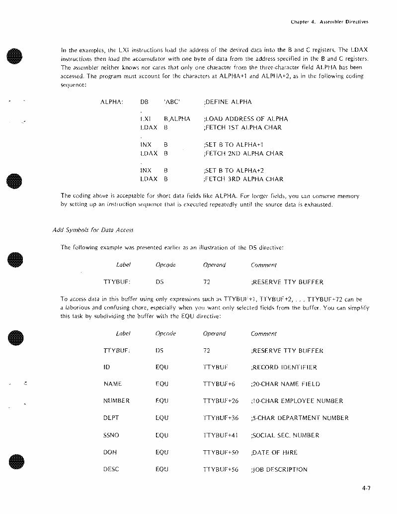
Chapter 4 Assembler Directives
In the the LXI instructions load the address of the desired data into the Band C registers The LDAX
instructions then load the accumulator with one byte of data from the address specified in the Band C
The assernbler neither knows nor cares that only one character from the threemiddotcharacter field ALPHA has been
accessed The program must account for the characters at ALPHA+j and ALPHA+2 as in the following coding
sequence
ALPHA DB ABC FINE ALPHA
LXI BALPHA ADDRESS OF ALPHA shy
LDAX B I ST ALPHA CHAR
INX B B TO ALPHA+j
LDAX B 2ND ALPHA CHAR
INX B B TO ALPHA+2 LDAX B 3RD ALPHA CHAR
The coding above is acceptable for short data fields like ALPHA For you can conserve memory
by setting up an instruction sequence that is executed until the source data is exhausted
Add Symbols for Data Access
The following example was nrcgtccgttgt earlier as an illustration of the DS directive
Label Opcode Comment
TTYBUF DS 72 TTY BUFFER
To access data in this buffer such as TTYBUF +1 TTYBUF+72 can be a laborious and confusing when you want only selected fields from the buffer You can simplify
this task by subdividing the buffer with the directive
Label Opcode Comment
TTYBUF DS 72 RVE TTY BUFFER
10 EQU TTYBUF RECORD IDENTIFIER
- NAME EQU TTYBUF+6 20middotCHAR NAME FIELD
NUMBER EQU TTYBUF+26 lOmiddotCHAR EMPLOYEE NUMBER
DEPT EQU TTYBUF+36 DEPARTMENT NUMBER
SSNO EQU TTYBUF+41 SEC NUMBER
DOH EQU TTYBUF+50 OF HIRE
DESC EQU TTYBUF+56 DESCRIPTION
4middot7
Chapter 4 Assembler Directives
Subdividing data as shown in the example simplifies data access and provides useful documentation throughout your program Notice that these EQU directives can be inserted anywhere within the program as you need them but coding them as shown in the example provides a more useful record description
CONDITIONAL ASSEMBLY
The I F ELSE and ENDIF directives enable you to assemble portions of your program conditionally that is only if certain conditions that you specify are satisfied
Conditional assembly is especially useful when your application requires custom programs for a number of comshy
mon options As an example assume that a basic control program requires customizing to accept input from one of six different sensing devices and to drive one of five different control devices Rather than code some thirty separate programs to account for all the possibilities you can code a single program The code for the inshydividual sensors and drivers must be enclosed by the conditional directives When you need to generate a custom program you can insert SET directives near the beginning of the source program to select the desired sensor and driver routines
IF ELSE ENDIF Directives
Because these directives arc used in conjunction they are described together here
Label Opcode Operand
optional IF expression
optional ELSE
optional ENDIF
The assembler evaluates the expression in the operand field of the IF directive If bit 0 of the resulting value is
one (TRUE ) all instructions between the IF directive and the next ELSE or ENDIF directive are assembled When bit 0 is zero (FALSE) these instructions are ignored (A TRUE expression evaluates to OFFFFH and FALSE to OH only bit zero need be tested)
All statements included between an IF directive and its required associated ENDIF directive are defined as an IF-ENDIF block The ELSE directive is optional and only one ELSE directive may appear in an IF-ENDIF block When included ELSE is the converse of IF When bit 0 of the expression in the IF directive is zero all statements between ELSE and the next ENDIF are assembled If bit 0 is one these statements are ignored
Operands are not allowed with the ELSE and ENDIF directives
An IF-EN D I F block may appear within another IF-END I F block These blocks can be nested to eight levels
Macro definitions (explained in the next chapter) may appear within an IF-ENDIF block Conversely IF-ENDIF blocks may appear within macro definitions In either case you must be certain to terminate the macro definition
bull
bull
bull
bull
bull 4-8
Chapter 4 Assembler Directives
bull or IF-ENDIF block so that it can be assembled completely For when a macro definition begins in an IF block but terminates after an ELSE only a portion of the macro can be assembled Similarly an
IF-ENDIF block within a macro definition must terminate within that same macro definition
NOTE
Caution is vhen symbols are defined in IF-ENDIF blocks and referenced elsewhere within the program These
symbols are undefined when the evaluation of the IF ex-suppresses the of the IF-ENDIF block
Example 1 Simple IF-ENDIF Block
bull COND1 IF TYPE EO 0
IF TYPE = 0
15 TRUE
ENDIF
2 IF -ELSE-ENDI F Block
bull COND2 IF TYPE 0
MBLED IF TYPE == 0 TRUE
ELSE
ASSEMBLED IF TYPE == 0 FALSE
bull ENDIF
bull 4-9
Chapter 4 Assembler Directives
-I
Example 3 Nested IFs
COND3 IF TYPE EO 0 bull ASSEMBLED IF TYPE = 0
IS TRUE
IF MODE EO 1
LEVEL ASSEMBLED IF TYPE = 0 AND MODE = l ARE BOTH
TRUE ENDIF ELSE
LEVEL ASSEMBLED IF TYPE 0
2 IS FALSE bull IF MODE EO 2
ASSEMBLED IF TYPE = 0 IS FALSE AND MODE = 2 IS TRUE
LEVEL ELSE
ASSEMBLED IF TYPE = 0 AND MODE = 2 ARE BOTH bullFALSE
ENDIF ENDIF
ASSEMBLER TERMINATION
END Directive bullThe END directive identifies the end of the source program and terminates each pass of the assembler
Label Opcode Operand
optional END expression
Only one END statement may appear in a source program and it must be the last source statement
If the optional expression is present its value is used as the starting address for program execution If no exmiddot pression is given the assembler assumes zero as the starting address
When a number of separate program modules are to be joined together only one may specify a program starting address The module with a starting address is the main module When source files are combined using the INshy
CLUDE control there are no restrictions on which source file contains the END bull 4-10
Chapter 4 Assembler Directives
bull END-OF-TAPE INDICATION
The EOT directive allows you to specify the physical end of paper tape to simplify assembly of multiple-tape source
programs
EOT Directive
Label Opcode Operand
optional EOT
When EOT is recognized by the assembler the message NEXT TAPE is sent to the console and the assembler pauses
After the next tape is loaded a space bar character rece ived at the console signals continuation of the assembly
bull Data in the operand field causes an error
LOCATION COUNTER CONTROL AND RELOCATION
All the directives discussed in the remainder of this chapter relate directly to program relocation except for the
ASEG and ORG directives These directives are described first for the convenience of readers who do not use the
relocation feature
bull Location Counter Control (Non-Relocatable Mode)
When you elect not to use the relocation feature an assembler default generates an ASEG directive for you The
ASEG directive specifies that the program is to be assembled in the non-relocatable mode and establishes a
location cou nter for the assembly
bull The location counter performs the same function for the assembler as the program counter performs during
execution It tells the assembler the next memory location available for instruction or data assembly
Initially the location counter is set to zero The location counter can be altered by the ORG (origin) directive
ORG Directive
The ORG directive sets the location counter to the value specified by the operand expression
Label Opcode Operand
optional ORG expression
The location counter is set to the value of the operand expression Assembly-time evaluation of ORG expressions
bull always yields a modulo 64K address Thus the expression always yields an address in the range 0 through
65535 Any symbol in the expression must be previously defined The next machine instruction or data item is
assembled at the specified address
4-11
Chapter 4 Assembler Directives
If no ORG directive is included before the first instruction or data byte in your program assembly begins at location zero
Your program can include any number of ORG directives Multiple ORGs need not specify addresses in ascending sequence but if you fail to do so you may instruct the assembler to write over some previously assembled portion of the program
If the optional label is present it is assigned the current value of the location counter before it is updated by the ORG directive
Example
Assume that the current value of the location counter is OFH (decimal 15) when the following ORG directive is encountered
PAG1 ORG OFFH ORG ASSEMBLER TO LOCATION
OFFH (decimal 225)
The symbol PAGI is assigned the address OFH The next instruction or data byte is assembled at location OFFH
Introduction to Relocatability
A major feature of this assembler is its system for creating relocatable object code modules Support for this new
feature includes a number of new directives for the assembler and three new programs included in ISIS-II The three new programs - LIB LINK and LOCATE _ arc described in the ISIS-Ii System Users Guide The new
assembler directives are described later in this chapter
Relocatability allows the programmer to code programs or sections of programs without worrying about the final arrangement of the object code in memory This offers developers of microcomputer systems major adshyvantages in two areas memory management and modular program development
Memory Management
When developing testing and debugging a system on your Intellec microcomputer development system your only concern with locating a program is that it doesnt overlap the resident routines of ISIS-II Because the Intellec system has 32K 48K or 64K of random access memory the location of your future program is not a great concern_ However the program you arc developing will almost certainly use some mix of random access memory (RAM) readmiddotonly memory (ROM) andor programmable read-only memory (PROM) Therefore the location of your program affects both cost dnd performance in your application The relocatability feature allows
you to develop test and debug your program on the Intellec development system and then simply relocate the object code to suit your application
The relocatability feature also has a major advantage at assembly-time often large programs with many symbols cannot be assembled because of limited work space for the symbol table Such a program can be divided into a
number of modules that can be assembled separately and then linked together to form a single object program
bull
bull
bull
bull
bull 4-12
Chapter 4 Assembler Directives
Modular Program Development
Although relocatability may seem to be a formidable term what it really means is that you can subdivide a
complex program into a number of smaller simpler programs This concept is best illustrated through the use of an example Assume thai a microcomputer program is to control the spark advance on an automobile engine This requires the program to sample the ambient air temperature engine air intake temperature coolant temperashyture manifold vacuum idle sensor and throttle sensor
Let us examine the approaches two different programmers might take to solve this problem Both programmers
want to calculate the degree of spark advance or retardation that provides the best fuel economy with the lowest
emissions Programmer A codes a single program that senses all inputs and calculates the correct spark advance
Programmer B uses a modular approach and codes separate programs for each input plus one program to calculate
spark advance
Although Programmer A avoids the need to learn to use the relocatability feature the modular approach used by Programmer B has a number of advantages you should consider
bull Simplified Program Development
It is generally easier to code test and debug several simple programs than one complex program
bull Sharing the Programming Task
If Programmer B finds that he is falling behind schedule he can assign one or more of his subshy
programs to another programmer Because of his single program concept Programmer A will
probably have to complete the program himself
bull Ease of Testing
Programmer B can lest and debug most of his modules as soon as they arc assembled Programmer
A must lest his program as a whol~ Notice that Programmer B has an extra advantage if the
sensors are being developed at the same lime as the program If one oflhe sensors is behind
schedule Programmer B can continue developing and testing programs for the sensors that arc
ready Because Programmer A cannot test his program until all the sensors are developed his
testing schedule is dependent on events beyond his control
bull Programming Changes
Given the nature of automotive design it is reasonable to expect some changes Juring system development If a change to one of the sensors requires a programming change Programmer A must search through his entire program to find and alter the coding for that sensor Then he must retest the entire program to be certain that those changes do not affect any of the other sensors
By contrast Programmer B need be concerned only with the module for that one sensor This
advantage continues throughout the life of the program
4middot13
Chapter 4 Assembler Directives
DIRECTIVES USED FOR RELOCATION
Several directives have been added to the assembler to support the relocation feature These fdll into the general
categories of location counter control and program linkage
Location Counter Control (Relocatable Programs)
Relocatable programs or program modules may use three locdtion counters The ASEG DSEG and CSEG
directive~ specify which location counter is to be used
The ASEG directive specifies dn dbsolute code segment Even in a relocdtable program module you may want to assign certain code segments to specific addresses For example restart routines invoked by the RST instrucshytion require specific addresses
The CSEG directive specifies a relocatable code segment In general the CSEG location counter is used for porshytions of the program that are to be in some form of read-only memory such as mdchine instructions and proshygram constants
The DSEG location counter specifies a relocdtdble data segment This location counter is used for program
elements that must be located in random access memory
These directives allow you to control program segmentation at assembly time The LOCATE program described in the ISIS-II System Users Guide gives you control over program segment location Therefore the guidelines given dbove are only generdl since they can be overridden by the LOCATE program
Regardless of how many times the ASEG CSEG and DSEG directives appear in your program the assembler produces a single contiguous module Th is module comprises four segments code data stack and memory The LINK and LOCATE programs are used to combine segments from individual modules and relocate them in
memory These programs are explained in the ISIS-II System Users Guide
ASEG Directive
ASEG directs the assembler to use the location counter for the dbsolute program segment
Label Opcode Operand
optional ASEG
Operands are not permitted with the ASEG directive
All instructions and data following the ASEG directive are dssembled in the absolute mode The ASEG directive
remains in effect until d CSEG or DSEG directive is encountered
The ASEG location counter has an initial value of zero The ORG directive can be used to dssign a new value to the ASEG location counter
bull
bull
bull
bull
bull 4-14
Chapter 4 Assembler Directives
When begins the assembler assurres the ASEG directive to be in effect Therefore a CSEG or DSEG
must the first instruction or data definition in a relocatable module If neither of these directives
appears in the program the entire program is assembltd in absolute mode and can be executed immediately
after without using the LINK or LOCATE programs
CSEG Directive
CSEG directs the assembler to assemble instructions and data in the relocatable mode the code
segment location counter
Label Opcode Operand
blank optional CSEG PAGE
INPAGE
When a program contains multiple CSEG all CSEG directives the program must specify
The operand of a CSEG directive has no effect on the current assembly but is stored with code to be to the LINK and LOCATE programs programs are described in the ISIS-II
The LOCATE program uses this information to determine relocation boundaries when it
joins this code segment to code segments from other programs The of the operand is as follows
bull blank This code segment may be relocated to the next available byte boundary
bull PAGE This code segment must when relocated boundaries
occur in multiples of 256 512 etc)
INPAGE -- This code segment must fit within a single page when relocated
The CSEG directive remains in effect until an ASEG or DSEG directive is encountered_
The code segment location counter has an initial value of zero The ORG directive can be used to a new
val ue to the CSEG location counter
DSEG Directive
DSEG directs the assembler to assemble subsequent instructions and data in the relocatable mode using the data
segment location counter
Label Operand
blank DSEG PAGE
INPAGE
When multiple DSEG directives appear in a program they must all specify the same throughout the
program The operands for the DSEG directive have the same meaning as for the CSEG directive except that
they apply to the data segment
4-15
Chapter 4 Assembler Directives
There is no interaction between the operands specified for the DSEG and CSEG directives Thus a code segment
can be byte relocatable while the data segment is page relocatable bull The DSEG directive remaim in effect IJntil an ASEG or CSEG directive is encountered
The data segment location counter has an initial value of zero The ORG directive can be used to assign a new
value to the DSEG location counter
ORG Directive (Relocalable Mode)
The ORG directive can be used to alter the value of the location counter presently in use
Label Opcode Operand
optional ORG expression bullThere are three location counters but only one location counter is in use at any given point in the program
Which one depends on whether the ASEG CSEG or DSEG directive is in effect
Any symbol used in the operand expression must have been previously defined An exception causes phase
errors for all labels that follow the ORG and a label error if the undefined error is defined later
When the ORG directive appears in a relocatable program segment the value of its operand expression must be
either absolute or relocatable within the current segment Thus if the ORG directive appears within a data segshy
ment the value of its expression must be relocatable within the data segment An error occurs if the expression bullevaluates to an address in the code segment
If the optional label is present it is assigned the current value of the location counter presently in use before
the ORG directive is executed
Program Linkage Directives
Modular programming and the relocation feature enable you to assemble and test a number of separate programs bullthat are to be joined together and executed as a single program Eventually it becomes necessary for these
separate programs to communicate information among themselves Establishing such communication is the
fu net ion of the program I inkage directives
A program may share its data addresses and instruction addresses with other programs Only items having an
entry in the symbol table can be shared with other programs therefore the item must be assigned a name or a
label when it is defined in the program I tems to be shared with other programs must be declared in a PUBLIC directive
Your program can directly access data or instructions defined in another program if you know the actual
address of the item but this is unlikely when both programs use relocation Your program can also gain access
to data or instructions declared as PUBLIC in other programs Notice however that the assembler normally
4-16
Chapter 4 Assembler Directives
flags as an error ltlny reference to ltl nltlme or lltlbel thltlt hltlS not been defined in your program To ltlvoid this
you must provide the assembler with ltl list of items used in your program but defined in some other program
These items must be declltlred in an EXTRN directive
The two remaining program linkage directives NAME and STKLN are individually explained later in this chltlpter
PUBLIC Directive
The PUBLIC directive makes each of the symbols listed in the operand field available for access by other programs
Label Opcode Operands
optionltll PUBLIC name-list
Each item in the operand name-list must be the name or label assigned to data or an instruction elsewhere in this program When multiple names appear in the list they must be seplttrated by commas Each nltlme may be declared PUBLIC only once in a program module Reserved words and externltll symbols (see the EXTRN directive below) cannot be declared to be PUBLIC symbols
PUBLIC directives may appear anywhere within a program module
if an item in the operand name-list has no corresponding entry in the symbol table (implying that it is undeshy
fined) it is flagged as an error
Example
PUBLIC SINCOSTANSQRT
EXTRN Directive
The EXTRN directive provides the assembler with a list of symbols referenced in this program but defined in a
different program Because of this the assembler establishes linkage to the other program and does not flag the
undefi ned references as errors
Label Opcode Operands
optional EXTRN name-list
Each item in the name-list identifies a symbol that may be referenced in this program but is defined in another program When multiple items appear in the list they must be separated by commas
If a symbol in the operand name-list is also defined in this program by the user or is a reserved symbol the effect
is the same as defining the same symbol more than once in a program The assembler flags this error
EXTRN directives may appear anywhere within a program module
A symbol may be declared to be external only once in a program module Symbols declared to be PUBLIC cannot also be declared to be EXTRN symbols
4-17
Chapter 4 Assembler Directives
If you omit a symbol from the name--list but reference it in the program the symbol is undefined The assembler
flags this error You may include symbols in the operand name--list that are not referenced in the program withshy bullout causing an error
Example
EXTRN ENTRYADDRTNBEGIN
NAME Directive
The NAME directive assigns a name to the object module generated by this assembly
Label Opcode Operand
optional NAME module-name bull The NAME directive requires the presence of a module-name in the operand field This name must conform to
the rules for defining symbols
Module names are necessary so that you can refer to a module and specify the proper sequence of modules
when a number of modules are to be bound together
The NAME directive must precede the first data or instruction coding in the source program but may follow
comments and control lines bullIf the NAME directive is missing from the program the assembler supplies a default NAME directive with the module-name MODULE This will cause an error if you attempt to bind together several object program modules and more than one has the name MODULE Also if you make an error coding the NAME directive the default name MODULE is assigned
The module - name assigned by the NAME directive appears as part of the page heading in the assembly listing
Example bullNAME MAIN
STKLN Directive
Regardless of the number of object program modules you may bind together only one stack is generated The
STKLN directive allows you to specify the number of bytes to be reserved for the stack for each module
Label Opcode Operand
optional STKLN expression
The operand expression must evaluate to a number which will be used as the maximum size of the stack bull 4middot18
Chapter 4 Assembler Directives
bull When the STKLN directive is omitted the provides a default STKLN of zero This is useful when multiple programs are bound only one stack will be so only one program module need
the stack size However you should provide a STKLN if your module is to be tested separately and uses the stack
If your program includes more than one STKLN directive the last value is retained
STKLN 100
STACI( and MEMORY Reserved Words
bull The reserved words STACK and MEMORY are not directives but are of interest to programmers using the relocation feature These reserved words are external references whose addresses are supplied by the LOCATE
program
STACK is the reference to the stack address You need this address to initialize the stack
pointer register Also you can base data structures on th is address symbolic references such as 5T ACK+1
etc
bull MEMORY is the symbolic reference to the first byte of unused memory the end of your program you can base data structures on this address symbolic such as MEMORY MEMORY+I etc
Programming Testing Rclocatable Modules
The ability to test individual program modules is a major of modular programming However many program modules are not self-sufficient and require some modification before they can be tested The following is a discussion of some of the more Common modifications that may be required
bull Initialization Routines
In most complete programs a number of or initialization are performed when execution first begins If the program module you are relies on initialization assigned to a different
you must duplicate those procedures in the module to be tested however that you can link any number of modules together for
One of the most important initialization is to set the stack The LOCATE program determines the origin of the stack
Your program should include the instruction to initialize the stack
LXI
bull 4middot19
Chapler 4 Assembler Direclives
InputOutput
When testing program modules it is likely that some input or output procedures appear in other modules Your bull program must simulate any of these procedures it needs to operate Since your Intellec development system
probably has considerably more random access memory than you need to test a program module you may be
able to simulate input and output data right in memory The LOCATE program supplies an address for the
reserved word MEMORY this is the address of the first byte of unused memory past the end of your program
You can access this memory using the symbolic reference MEMORY MEMORY+l and so on This memory can be used for storing test data or even for a program that generates test data
Remove Coding Used for Testing
After testing your program be certain to remove any code you inserted for testing In particular make certain that only one module in the complete program initializes the stack pointer bull
bull
bull
bull 4-20
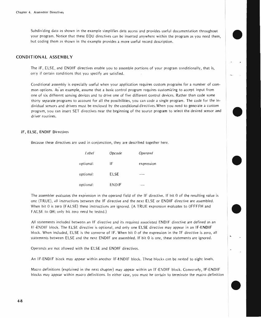
Chapter 4 Assembler Directives
Subdividing data as shown in the example simplifies data access and provides useful documentation throughout your program Notice that these EQU directives can be inserted anywhere within the program as you need them but coding them as shown in the example provides a more useful record description
CONDITIONAL ASSEMBLY
The I F ELSE and ENDIF directives enable you to assemble portions of your program conditionally that is only if certain conditions that you specify are satisfied
Conditional assembly is especially useful when your application requires custom programs for a number of comshy
mon options As an example assume that a basic control program requires customizing to accept input from one of six different sensing devices and to drive one of five different control devices Rather than code some thirty separate programs to account for all the possibilities you can code a single program The code for the inshydividual sensors and drivers must be enclosed by the conditional directives When you need to generate a custom program you can insert SET directives near the beginning of the source program to select the desired sensor and driver routines
IF ELSE ENDIF Directives
Because these directives arc used in conjunction they are described together here
Label Opcode Operand
optional IF expression
optional ELSE
optional ENDIF
The assembler evaluates the expression in the operand field of the IF directive If bit 0 of the resulting value is
one (TRUE ) all instructions between the IF directive and the next ELSE or ENDIF directive are assembled When bit 0 is zero (FALSE) these instructions are ignored (A TRUE expression evaluates to OFFFFH and FALSE to OH only bit zero need be tested)
All statements included between an IF directive and its required associated ENDIF directive are defined as an IF-ENDIF block The ELSE directive is optional and only one ELSE directive may appear in an IF-ENDIF block When included ELSE is the converse of IF When bit 0 of the expression in the IF directive is zero all statements between ELSE and the next ENDIF are assembled If bit 0 is one these statements are ignored
Operands are not allowed with the ELSE and ENDIF directives
An IF-EN D I F block may appear within another IF-END I F block These blocks can be nested to eight levels
Macro definitions (explained in the next chapter) may appear within an IF-ENDIF block Conversely IF-ENDIF blocks may appear within macro definitions In either case you must be certain to terminate the macro definition
bull
bull
bull
bull
bull 4-8
Chapter 4 Assembler Directives
bull or IF-ENDIF block so that it can be assembled completely For when a macro definition begins in an IF block but terminates after an ELSE only a portion of the macro can be assembled Similarly an
IF-ENDIF block within a macro definition must terminate within that same macro definition
NOTE
Caution is vhen symbols are defined in IF-ENDIF blocks and referenced elsewhere within the program These
symbols are undefined when the evaluation of the IF ex-suppresses the of the IF-ENDIF block
Example 1 Simple IF-ENDIF Block
bull COND1 IF TYPE EO 0
IF TYPE = 0
15 TRUE
ENDIF
2 IF -ELSE-ENDI F Block
bull COND2 IF TYPE 0
MBLED IF TYPE == 0 TRUE
ELSE
ASSEMBLED IF TYPE == 0 FALSE
bull ENDIF
bull 4-9
Chapter 4 Assembler Directives
-I
Example 3 Nested IFs
COND3 IF TYPE EO 0 bull ASSEMBLED IF TYPE = 0
IS TRUE
IF MODE EO 1
LEVEL ASSEMBLED IF TYPE = 0 AND MODE = l ARE BOTH
TRUE ENDIF ELSE
LEVEL ASSEMBLED IF TYPE 0
2 IS FALSE bull IF MODE EO 2
ASSEMBLED IF TYPE = 0 IS FALSE AND MODE = 2 IS TRUE
LEVEL ELSE
ASSEMBLED IF TYPE = 0 AND MODE = 2 ARE BOTH bullFALSE
ENDIF ENDIF
ASSEMBLER TERMINATION
END Directive bullThe END directive identifies the end of the source program and terminates each pass of the assembler
Label Opcode Operand
optional END expression
Only one END statement may appear in a source program and it must be the last source statement
If the optional expression is present its value is used as the starting address for program execution If no exmiddot pression is given the assembler assumes zero as the starting address
When a number of separate program modules are to be joined together only one may specify a program starting address The module with a starting address is the main module When source files are combined using the INshy
CLUDE control there are no restrictions on which source file contains the END bull 4-10
Chapter 4 Assembler Directives
bull END-OF-TAPE INDICATION
The EOT directive allows you to specify the physical end of paper tape to simplify assembly of multiple-tape source
programs
EOT Directive
Label Opcode Operand
optional EOT
When EOT is recognized by the assembler the message NEXT TAPE is sent to the console and the assembler pauses
After the next tape is loaded a space bar character rece ived at the console signals continuation of the assembly
bull Data in the operand field causes an error
LOCATION COUNTER CONTROL AND RELOCATION
All the directives discussed in the remainder of this chapter relate directly to program relocation except for the
ASEG and ORG directives These directives are described first for the convenience of readers who do not use the
relocation feature
bull Location Counter Control (Non-Relocatable Mode)
When you elect not to use the relocation feature an assembler default generates an ASEG directive for you The
ASEG directive specifies that the program is to be assembled in the non-relocatable mode and establishes a
location cou nter for the assembly
bull The location counter performs the same function for the assembler as the program counter performs during
execution It tells the assembler the next memory location available for instruction or data assembly
Initially the location counter is set to zero The location counter can be altered by the ORG (origin) directive
ORG Directive
The ORG directive sets the location counter to the value specified by the operand expression
Label Opcode Operand
optional ORG expression
The location counter is set to the value of the operand expression Assembly-time evaluation of ORG expressions
bull always yields a modulo 64K address Thus the expression always yields an address in the range 0 through
65535 Any symbol in the expression must be previously defined The next machine instruction or data item is
assembled at the specified address
4-11
Chapter 4 Assembler Directives
If no ORG directive is included before the first instruction or data byte in your program assembly begins at location zero
Your program can include any number of ORG directives Multiple ORGs need not specify addresses in ascending sequence but if you fail to do so you may instruct the assembler to write over some previously assembled portion of the program
If the optional label is present it is assigned the current value of the location counter before it is updated by the ORG directive
Example
Assume that the current value of the location counter is OFH (decimal 15) when the following ORG directive is encountered
PAG1 ORG OFFH ORG ASSEMBLER TO LOCATION
OFFH (decimal 225)
The symbol PAGI is assigned the address OFH The next instruction or data byte is assembled at location OFFH
Introduction to Relocatability
A major feature of this assembler is its system for creating relocatable object code modules Support for this new
feature includes a number of new directives for the assembler and three new programs included in ISIS-II The three new programs - LIB LINK and LOCATE _ arc described in the ISIS-Ii System Users Guide The new
assembler directives are described later in this chapter
Relocatability allows the programmer to code programs or sections of programs without worrying about the final arrangement of the object code in memory This offers developers of microcomputer systems major adshyvantages in two areas memory management and modular program development
Memory Management
When developing testing and debugging a system on your Intellec microcomputer development system your only concern with locating a program is that it doesnt overlap the resident routines of ISIS-II Because the Intellec system has 32K 48K or 64K of random access memory the location of your future program is not a great concern_ However the program you arc developing will almost certainly use some mix of random access memory (RAM) readmiddotonly memory (ROM) andor programmable read-only memory (PROM) Therefore the location of your program affects both cost dnd performance in your application The relocatability feature allows
you to develop test and debug your program on the Intellec development system and then simply relocate the object code to suit your application
The relocatability feature also has a major advantage at assembly-time often large programs with many symbols cannot be assembled because of limited work space for the symbol table Such a program can be divided into a
number of modules that can be assembled separately and then linked together to form a single object program
bull
bull
bull
bull
bull 4-12
Chapter 4 Assembler Directives
Modular Program Development
Although relocatability may seem to be a formidable term what it really means is that you can subdivide a
complex program into a number of smaller simpler programs This concept is best illustrated through the use of an example Assume thai a microcomputer program is to control the spark advance on an automobile engine This requires the program to sample the ambient air temperature engine air intake temperature coolant temperashyture manifold vacuum idle sensor and throttle sensor
Let us examine the approaches two different programmers might take to solve this problem Both programmers
want to calculate the degree of spark advance or retardation that provides the best fuel economy with the lowest
emissions Programmer A codes a single program that senses all inputs and calculates the correct spark advance
Programmer B uses a modular approach and codes separate programs for each input plus one program to calculate
spark advance
Although Programmer A avoids the need to learn to use the relocatability feature the modular approach used by Programmer B has a number of advantages you should consider
bull Simplified Program Development
It is generally easier to code test and debug several simple programs than one complex program
bull Sharing the Programming Task
If Programmer B finds that he is falling behind schedule he can assign one or more of his subshy
programs to another programmer Because of his single program concept Programmer A will
probably have to complete the program himself
bull Ease of Testing
Programmer B can lest and debug most of his modules as soon as they arc assembled Programmer
A must lest his program as a whol~ Notice that Programmer B has an extra advantage if the
sensors are being developed at the same lime as the program If one oflhe sensors is behind
schedule Programmer B can continue developing and testing programs for the sensors that arc
ready Because Programmer A cannot test his program until all the sensors are developed his
testing schedule is dependent on events beyond his control
bull Programming Changes
Given the nature of automotive design it is reasonable to expect some changes Juring system development If a change to one of the sensors requires a programming change Programmer A must search through his entire program to find and alter the coding for that sensor Then he must retest the entire program to be certain that those changes do not affect any of the other sensors
By contrast Programmer B need be concerned only with the module for that one sensor This
advantage continues throughout the life of the program
4middot13
Chapter 4 Assembler Directives
DIRECTIVES USED FOR RELOCATION
Several directives have been added to the assembler to support the relocation feature These fdll into the general
categories of location counter control and program linkage
Location Counter Control (Relocatable Programs)
Relocatable programs or program modules may use three locdtion counters The ASEG DSEG and CSEG
directive~ specify which location counter is to be used
The ASEG directive specifies dn dbsolute code segment Even in a relocdtable program module you may want to assign certain code segments to specific addresses For example restart routines invoked by the RST instrucshytion require specific addresses
The CSEG directive specifies a relocatable code segment In general the CSEG location counter is used for porshytions of the program that are to be in some form of read-only memory such as mdchine instructions and proshygram constants
The DSEG location counter specifies a relocdtdble data segment This location counter is used for program
elements that must be located in random access memory
These directives allow you to control program segmentation at assembly time The LOCATE program described in the ISIS-II System Users Guide gives you control over program segment location Therefore the guidelines given dbove are only generdl since they can be overridden by the LOCATE program
Regardless of how many times the ASEG CSEG and DSEG directives appear in your program the assembler produces a single contiguous module Th is module comprises four segments code data stack and memory The LINK and LOCATE programs are used to combine segments from individual modules and relocate them in
memory These programs are explained in the ISIS-II System Users Guide
ASEG Directive
ASEG directs the assembler to use the location counter for the dbsolute program segment
Label Opcode Operand
optional ASEG
Operands are not permitted with the ASEG directive
All instructions and data following the ASEG directive are dssembled in the absolute mode The ASEG directive
remains in effect until d CSEG or DSEG directive is encountered
The ASEG location counter has an initial value of zero The ORG directive can be used to dssign a new value to the ASEG location counter
bull
bull
bull
bull
bull 4-14
Chapter 4 Assembler Directives
When begins the assembler assurres the ASEG directive to be in effect Therefore a CSEG or DSEG
must the first instruction or data definition in a relocatable module If neither of these directives
appears in the program the entire program is assembltd in absolute mode and can be executed immediately
after without using the LINK or LOCATE programs
CSEG Directive
CSEG directs the assembler to assemble instructions and data in the relocatable mode the code
segment location counter
Label Opcode Operand
blank optional CSEG PAGE
INPAGE
When a program contains multiple CSEG all CSEG directives the program must specify
The operand of a CSEG directive has no effect on the current assembly but is stored with code to be to the LINK and LOCATE programs programs are described in the ISIS-II
The LOCATE program uses this information to determine relocation boundaries when it
joins this code segment to code segments from other programs The of the operand is as follows
bull blank This code segment may be relocated to the next available byte boundary
bull PAGE This code segment must when relocated boundaries
occur in multiples of 256 512 etc)
INPAGE -- This code segment must fit within a single page when relocated
The CSEG directive remains in effect until an ASEG or DSEG directive is encountered_
The code segment location counter has an initial value of zero The ORG directive can be used to a new
val ue to the CSEG location counter
DSEG Directive
DSEG directs the assembler to assemble subsequent instructions and data in the relocatable mode using the data
segment location counter
Label Operand
blank DSEG PAGE
INPAGE
When multiple DSEG directives appear in a program they must all specify the same throughout the
program The operands for the DSEG directive have the same meaning as for the CSEG directive except that
they apply to the data segment
4-15
Chapter 4 Assembler Directives
There is no interaction between the operands specified for the DSEG and CSEG directives Thus a code segment
can be byte relocatable while the data segment is page relocatable bull The DSEG directive remaim in effect IJntil an ASEG or CSEG directive is encountered
The data segment location counter has an initial value of zero The ORG directive can be used to assign a new
value to the DSEG location counter
ORG Directive (Relocalable Mode)
The ORG directive can be used to alter the value of the location counter presently in use
Label Opcode Operand
optional ORG expression bullThere are three location counters but only one location counter is in use at any given point in the program
Which one depends on whether the ASEG CSEG or DSEG directive is in effect
Any symbol used in the operand expression must have been previously defined An exception causes phase
errors for all labels that follow the ORG and a label error if the undefined error is defined later
When the ORG directive appears in a relocatable program segment the value of its operand expression must be
either absolute or relocatable within the current segment Thus if the ORG directive appears within a data segshy
ment the value of its expression must be relocatable within the data segment An error occurs if the expression bullevaluates to an address in the code segment
If the optional label is present it is assigned the current value of the location counter presently in use before
the ORG directive is executed
Program Linkage Directives
Modular programming and the relocation feature enable you to assemble and test a number of separate programs bullthat are to be joined together and executed as a single program Eventually it becomes necessary for these
separate programs to communicate information among themselves Establishing such communication is the
fu net ion of the program I inkage directives
A program may share its data addresses and instruction addresses with other programs Only items having an
entry in the symbol table can be shared with other programs therefore the item must be assigned a name or a
label when it is defined in the program I tems to be shared with other programs must be declared in a PUBLIC directive
Your program can directly access data or instructions defined in another program if you know the actual
address of the item but this is unlikely when both programs use relocation Your program can also gain access
to data or instructions declared as PUBLIC in other programs Notice however that the assembler normally
4-16
Chapter 4 Assembler Directives
flags as an error ltlny reference to ltl nltlme or lltlbel thltlt hltlS not been defined in your program To ltlvoid this
you must provide the assembler with ltl list of items used in your program but defined in some other program
These items must be declltlred in an EXTRN directive
The two remaining program linkage directives NAME and STKLN are individually explained later in this chltlpter
PUBLIC Directive
The PUBLIC directive makes each of the symbols listed in the operand field available for access by other programs
Label Opcode Operands
optionltll PUBLIC name-list
Each item in the operand name-list must be the name or label assigned to data or an instruction elsewhere in this program When multiple names appear in the list they must be seplttrated by commas Each nltlme may be declared PUBLIC only once in a program module Reserved words and externltll symbols (see the EXTRN directive below) cannot be declared to be PUBLIC symbols
PUBLIC directives may appear anywhere within a program module
if an item in the operand name-list has no corresponding entry in the symbol table (implying that it is undeshy
fined) it is flagged as an error
Example
PUBLIC SINCOSTANSQRT
EXTRN Directive
The EXTRN directive provides the assembler with a list of symbols referenced in this program but defined in a
different program Because of this the assembler establishes linkage to the other program and does not flag the
undefi ned references as errors
Label Opcode Operands
optional EXTRN name-list
Each item in the name-list identifies a symbol that may be referenced in this program but is defined in another program When multiple items appear in the list they must be separated by commas
If a symbol in the operand name-list is also defined in this program by the user or is a reserved symbol the effect
is the same as defining the same symbol more than once in a program The assembler flags this error
EXTRN directives may appear anywhere within a program module
A symbol may be declared to be external only once in a program module Symbols declared to be PUBLIC cannot also be declared to be EXTRN symbols
4-17
Chapter 4 Assembler Directives
If you omit a symbol from the name--list but reference it in the program the symbol is undefined The assembler
flags this error You may include symbols in the operand name--list that are not referenced in the program withshy bullout causing an error
Example
EXTRN ENTRYADDRTNBEGIN
NAME Directive
The NAME directive assigns a name to the object module generated by this assembly
Label Opcode Operand
optional NAME module-name bull The NAME directive requires the presence of a module-name in the operand field This name must conform to
the rules for defining symbols
Module names are necessary so that you can refer to a module and specify the proper sequence of modules
when a number of modules are to be bound together
The NAME directive must precede the first data or instruction coding in the source program but may follow
comments and control lines bullIf the NAME directive is missing from the program the assembler supplies a default NAME directive with the module-name MODULE This will cause an error if you attempt to bind together several object program modules and more than one has the name MODULE Also if you make an error coding the NAME directive the default name MODULE is assigned
The module - name assigned by the NAME directive appears as part of the page heading in the assembly listing
Example bullNAME MAIN
STKLN Directive
Regardless of the number of object program modules you may bind together only one stack is generated The
STKLN directive allows you to specify the number of bytes to be reserved for the stack for each module
Label Opcode Operand
optional STKLN expression
The operand expression must evaluate to a number which will be used as the maximum size of the stack bull 4middot18
Chapter 4 Assembler Directives
bull When the STKLN directive is omitted the provides a default STKLN of zero This is useful when multiple programs are bound only one stack will be so only one program module need
the stack size However you should provide a STKLN if your module is to be tested separately and uses the stack
If your program includes more than one STKLN directive the last value is retained
STKLN 100
STACI( and MEMORY Reserved Words
bull The reserved words STACK and MEMORY are not directives but are of interest to programmers using the relocation feature These reserved words are external references whose addresses are supplied by the LOCATE
program
STACK is the reference to the stack address You need this address to initialize the stack
pointer register Also you can base data structures on th is address symbolic references such as 5T ACK+1
etc
bull MEMORY is the symbolic reference to the first byte of unused memory the end of your program you can base data structures on this address symbolic such as MEMORY MEMORY+I etc
Programming Testing Rclocatable Modules
The ability to test individual program modules is a major of modular programming However many program modules are not self-sufficient and require some modification before they can be tested The following is a discussion of some of the more Common modifications that may be required
bull Initialization Routines
In most complete programs a number of or initialization are performed when execution first begins If the program module you are relies on initialization assigned to a different
you must duplicate those procedures in the module to be tested however that you can link any number of modules together for
One of the most important initialization is to set the stack The LOCATE program determines the origin of the stack
Your program should include the instruction to initialize the stack
LXI
bull 4middot19
Chapler 4 Assembler Direclives
InputOutput
When testing program modules it is likely that some input or output procedures appear in other modules Your bull program must simulate any of these procedures it needs to operate Since your Intellec development system
probably has considerably more random access memory than you need to test a program module you may be
able to simulate input and output data right in memory The LOCATE program supplies an address for the
reserved word MEMORY this is the address of the first byte of unused memory past the end of your program
You can access this memory using the symbolic reference MEMORY MEMORY+l and so on This memory can be used for storing test data or even for a program that generates test data
Remove Coding Used for Testing
After testing your program be certain to remove any code you inserted for testing In particular make certain that only one module in the complete program initializes the stack pointer bull
bull
bull
bull 4-20
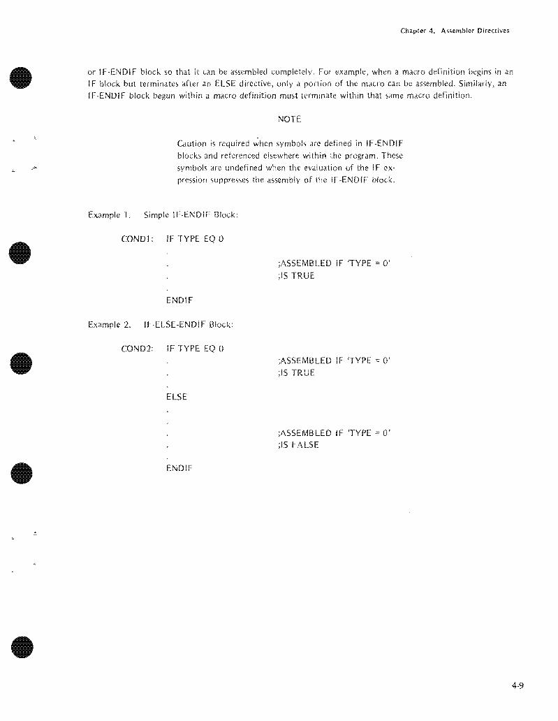
Chapter 4 Assembler Directives
bull or IF-ENDIF block so that it can be assembled completely For when a macro definition begins in an IF block but terminates after an ELSE only a portion of the macro can be assembled Similarly an
IF-ENDIF block within a macro definition must terminate within that same macro definition
NOTE
Caution is vhen symbols are defined in IF-ENDIF blocks and referenced elsewhere within the program These
symbols are undefined when the evaluation of the IF ex-suppresses the of the IF-ENDIF block
Example 1 Simple IF-ENDIF Block
bull COND1 IF TYPE EO 0
IF TYPE = 0
15 TRUE
ENDIF
2 IF -ELSE-ENDI F Block
bull COND2 IF TYPE 0
MBLED IF TYPE == 0 TRUE
ELSE
ASSEMBLED IF TYPE == 0 FALSE
bull ENDIF
bull 4-9
Chapter 4 Assembler Directives
-I
Example 3 Nested IFs
COND3 IF TYPE EO 0 bull ASSEMBLED IF TYPE = 0
IS TRUE
IF MODE EO 1
LEVEL ASSEMBLED IF TYPE = 0 AND MODE = l ARE BOTH
TRUE ENDIF ELSE
LEVEL ASSEMBLED IF TYPE 0
2 IS FALSE bull IF MODE EO 2
ASSEMBLED IF TYPE = 0 IS FALSE AND MODE = 2 IS TRUE
LEVEL ELSE
ASSEMBLED IF TYPE = 0 AND MODE = 2 ARE BOTH bullFALSE
ENDIF ENDIF
ASSEMBLER TERMINATION
END Directive bullThe END directive identifies the end of the source program and terminates each pass of the assembler
Label Opcode Operand
optional END expression
Only one END statement may appear in a source program and it must be the last source statement
If the optional expression is present its value is used as the starting address for program execution If no exmiddot pression is given the assembler assumes zero as the starting address
When a number of separate program modules are to be joined together only one may specify a program starting address The module with a starting address is the main module When source files are combined using the INshy
CLUDE control there are no restrictions on which source file contains the END bull 4-10
Chapter 4 Assembler Directives
bull END-OF-TAPE INDICATION
The EOT directive allows you to specify the physical end of paper tape to simplify assembly of multiple-tape source
programs
EOT Directive
Label Opcode Operand
optional EOT
When EOT is recognized by the assembler the message NEXT TAPE is sent to the console and the assembler pauses
After the next tape is loaded a space bar character rece ived at the console signals continuation of the assembly
bull Data in the operand field causes an error
LOCATION COUNTER CONTROL AND RELOCATION
All the directives discussed in the remainder of this chapter relate directly to program relocation except for the
ASEG and ORG directives These directives are described first for the convenience of readers who do not use the
relocation feature
bull Location Counter Control (Non-Relocatable Mode)
When you elect not to use the relocation feature an assembler default generates an ASEG directive for you The
ASEG directive specifies that the program is to be assembled in the non-relocatable mode and establishes a
location cou nter for the assembly
bull The location counter performs the same function for the assembler as the program counter performs during
execution It tells the assembler the next memory location available for instruction or data assembly
Initially the location counter is set to zero The location counter can be altered by the ORG (origin) directive
ORG Directive
The ORG directive sets the location counter to the value specified by the operand expression
Label Opcode Operand
optional ORG expression
The location counter is set to the value of the operand expression Assembly-time evaluation of ORG expressions
bull always yields a modulo 64K address Thus the expression always yields an address in the range 0 through
65535 Any symbol in the expression must be previously defined The next machine instruction or data item is
assembled at the specified address
4-11
Chapter 4 Assembler Directives
If no ORG directive is included before the first instruction or data byte in your program assembly begins at location zero
Your program can include any number of ORG directives Multiple ORGs need not specify addresses in ascending sequence but if you fail to do so you may instruct the assembler to write over some previously assembled portion of the program
If the optional label is present it is assigned the current value of the location counter before it is updated by the ORG directive
Example
Assume that the current value of the location counter is OFH (decimal 15) when the following ORG directive is encountered
PAG1 ORG OFFH ORG ASSEMBLER TO LOCATION
OFFH (decimal 225)
The symbol PAGI is assigned the address OFH The next instruction or data byte is assembled at location OFFH
Introduction to Relocatability
A major feature of this assembler is its system for creating relocatable object code modules Support for this new
feature includes a number of new directives for the assembler and three new programs included in ISIS-II The three new programs - LIB LINK and LOCATE _ arc described in the ISIS-Ii System Users Guide The new
assembler directives are described later in this chapter
Relocatability allows the programmer to code programs or sections of programs without worrying about the final arrangement of the object code in memory This offers developers of microcomputer systems major adshyvantages in two areas memory management and modular program development
Memory Management
When developing testing and debugging a system on your Intellec microcomputer development system your only concern with locating a program is that it doesnt overlap the resident routines of ISIS-II Because the Intellec system has 32K 48K or 64K of random access memory the location of your future program is not a great concern_ However the program you arc developing will almost certainly use some mix of random access memory (RAM) readmiddotonly memory (ROM) andor programmable read-only memory (PROM) Therefore the location of your program affects both cost dnd performance in your application The relocatability feature allows
you to develop test and debug your program on the Intellec development system and then simply relocate the object code to suit your application
The relocatability feature also has a major advantage at assembly-time often large programs with many symbols cannot be assembled because of limited work space for the symbol table Such a program can be divided into a
number of modules that can be assembled separately and then linked together to form a single object program
bull
bull
bull
bull
bull 4-12
Chapter 4 Assembler Directives
Modular Program Development
Although relocatability may seem to be a formidable term what it really means is that you can subdivide a
complex program into a number of smaller simpler programs This concept is best illustrated through the use of an example Assume thai a microcomputer program is to control the spark advance on an automobile engine This requires the program to sample the ambient air temperature engine air intake temperature coolant temperashyture manifold vacuum idle sensor and throttle sensor
Let us examine the approaches two different programmers might take to solve this problem Both programmers
want to calculate the degree of spark advance or retardation that provides the best fuel economy with the lowest
emissions Programmer A codes a single program that senses all inputs and calculates the correct spark advance
Programmer B uses a modular approach and codes separate programs for each input plus one program to calculate
spark advance
Although Programmer A avoids the need to learn to use the relocatability feature the modular approach used by Programmer B has a number of advantages you should consider
bull Simplified Program Development
It is generally easier to code test and debug several simple programs than one complex program
bull Sharing the Programming Task
If Programmer B finds that he is falling behind schedule he can assign one or more of his subshy
programs to another programmer Because of his single program concept Programmer A will
probably have to complete the program himself
bull Ease of Testing
Programmer B can lest and debug most of his modules as soon as they arc assembled Programmer
A must lest his program as a whol~ Notice that Programmer B has an extra advantage if the
sensors are being developed at the same lime as the program If one oflhe sensors is behind
schedule Programmer B can continue developing and testing programs for the sensors that arc
ready Because Programmer A cannot test his program until all the sensors are developed his
testing schedule is dependent on events beyond his control
bull Programming Changes
Given the nature of automotive design it is reasonable to expect some changes Juring system development If a change to one of the sensors requires a programming change Programmer A must search through his entire program to find and alter the coding for that sensor Then he must retest the entire program to be certain that those changes do not affect any of the other sensors
By contrast Programmer B need be concerned only with the module for that one sensor This
advantage continues throughout the life of the program
4middot13
Chapter 4 Assembler Directives
DIRECTIVES USED FOR RELOCATION
Several directives have been added to the assembler to support the relocation feature These fdll into the general
categories of location counter control and program linkage
Location Counter Control (Relocatable Programs)
Relocatable programs or program modules may use three locdtion counters The ASEG DSEG and CSEG
directive~ specify which location counter is to be used
The ASEG directive specifies dn dbsolute code segment Even in a relocdtable program module you may want to assign certain code segments to specific addresses For example restart routines invoked by the RST instrucshytion require specific addresses
The CSEG directive specifies a relocatable code segment In general the CSEG location counter is used for porshytions of the program that are to be in some form of read-only memory such as mdchine instructions and proshygram constants
The DSEG location counter specifies a relocdtdble data segment This location counter is used for program
elements that must be located in random access memory
These directives allow you to control program segmentation at assembly time The LOCATE program described in the ISIS-II System Users Guide gives you control over program segment location Therefore the guidelines given dbove are only generdl since they can be overridden by the LOCATE program
Regardless of how many times the ASEG CSEG and DSEG directives appear in your program the assembler produces a single contiguous module Th is module comprises four segments code data stack and memory The LINK and LOCATE programs are used to combine segments from individual modules and relocate them in
memory These programs are explained in the ISIS-II System Users Guide
ASEG Directive
ASEG directs the assembler to use the location counter for the dbsolute program segment
Label Opcode Operand
optional ASEG
Operands are not permitted with the ASEG directive
All instructions and data following the ASEG directive are dssembled in the absolute mode The ASEG directive
remains in effect until d CSEG or DSEG directive is encountered
The ASEG location counter has an initial value of zero The ORG directive can be used to dssign a new value to the ASEG location counter
bull
bull
bull
bull
bull 4-14
Chapter 4 Assembler Directives
When begins the assembler assurres the ASEG directive to be in effect Therefore a CSEG or DSEG
must the first instruction or data definition in a relocatable module If neither of these directives
appears in the program the entire program is assembltd in absolute mode and can be executed immediately
after without using the LINK or LOCATE programs
CSEG Directive
CSEG directs the assembler to assemble instructions and data in the relocatable mode the code
segment location counter
Label Opcode Operand
blank optional CSEG PAGE
INPAGE
When a program contains multiple CSEG all CSEG directives the program must specify
The operand of a CSEG directive has no effect on the current assembly but is stored with code to be to the LINK and LOCATE programs programs are described in the ISIS-II
The LOCATE program uses this information to determine relocation boundaries when it
joins this code segment to code segments from other programs The of the operand is as follows
bull blank This code segment may be relocated to the next available byte boundary
bull PAGE This code segment must when relocated boundaries
occur in multiples of 256 512 etc)
INPAGE -- This code segment must fit within a single page when relocated
The CSEG directive remains in effect until an ASEG or DSEG directive is encountered_
The code segment location counter has an initial value of zero The ORG directive can be used to a new
val ue to the CSEG location counter
DSEG Directive
DSEG directs the assembler to assemble subsequent instructions and data in the relocatable mode using the data
segment location counter
Label Operand
blank DSEG PAGE
INPAGE
When multiple DSEG directives appear in a program they must all specify the same throughout the
program The operands for the DSEG directive have the same meaning as for the CSEG directive except that
they apply to the data segment
4-15
Chapter 4 Assembler Directives
There is no interaction between the operands specified for the DSEG and CSEG directives Thus a code segment
can be byte relocatable while the data segment is page relocatable bull The DSEG directive remaim in effect IJntil an ASEG or CSEG directive is encountered
The data segment location counter has an initial value of zero The ORG directive can be used to assign a new
value to the DSEG location counter
ORG Directive (Relocalable Mode)
The ORG directive can be used to alter the value of the location counter presently in use
Label Opcode Operand
optional ORG expression bullThere are three location counters but only one location counter is in use at any given point in the program
Which one depends on whether the ASEG CSEG or DSEG directive is in effect
Any symbol used in the operand expression must have been previously defined An exception causes phase
errors for all labels that follow the ORG and a label error if the undefined error is defined later
When the ORG directive appears in a relocatable program segment the value of its operand expression must be
either absolute or relocatable within the current segment Thus if the ORG directive appears within a data segshy
ment the value of its expression must be relocatable within the data segment An error occurs if the expression bullevaluates to an address in the code segment
If the optional label is present it is assigned the current value of the location counter presently in use before
the ORG directive is executed
Program Linkage Directives
Modular programming and the relocation feature enable you to assemble and test a number of separate programs bullthat are to be joined together and executed as a single program Eventually it becomes necessary for these
separate programs to communicate information among themselves Establishing such communication is the
fu net ion of the program I inkage directives
A program may share its data addresses and instruction addresses with other programs Only items having an
entry in the symbol table can be shared with other programs therefore the item must be assigned a name or a
label when it is defined in the program I tems to be shared with other programs must be declared in a PUBLIC directive
Your program can directly access data or instructions defined in another program if you know the actual
address of the item but this is unlikely when both programs use relocation Your program can also gain access
to data or instructions declared as PUBLIC in other programs Notice however that the assembler normally
4-16
Chapter 4 Assembler Directives
flags as an error ltlny reference to ltl nltlme or lltlbel thltlt hltlS not been defined in your program To ltlvoid this
you must provide the assembler with ltl list of items used in your program but defined in some other program
These items must be declltlred in an EXTRN directive
The two remaining program linkage directives NAME and STKLN are individually explained later in this chltlpter
PUBLIC Directive
The PUBLIC directive makes each of the symbols listed in the operand field available for access by other programs
Label Opcode Operands
optionltll PUBLIC name-list
Each item in the operand name-list must be the name or label assigned to data or an instruction elsewhere in this program When multiple names appear in the list they must be seplttrated by commas Each nltlme may be declared PUBLIC only once in a program module Reserved words and externltll symbols (see the EXTRN directive below) cannot be declared to be PUBLIC symbols
PUBLIC directives may appear anywhere within a program module
if an item in the operand name-list has no corresponding entry in the symbol table (implying that it is undeshy
fined) it is flagged as an error
Example
PUBLIC SINCOSTANSQRT
EXTRN Directive
The EXTRN directive provides the assembler with a list of symbols referenced in this program but defined in a
different program Because of this the assembler establishes linkage to the other program and does not flag the
undefi ned references as errors
Label Opcode Operands
optional EXTRN name-list
Each item in the name-list identifies a symbol that may be referenced in this program but is defined in another program When multiple items appear in the list they must be separated by commas
If a symbol in the operand name-list is also defined in this program by the user or is a reserved symbol the effect
is the same as defining the same symbol more than once in a program The assembler flags this error
EXTRN directives may appear anywhere within a program module
A symbol may be declared to be external only once in a program module Symbols declared to be PUBLIC cannot also be declared to be EXTRN symbols
4-17
Chapter 4 Assembler Directives
If you omit a symbol from the name--list but reference it in the program the symbol is undefined The assembler
flags this error You may include symbols in the operand name--list that are not referenced in the program withshy bullout causing an error
Example
EXTRN ENTRYADDRTNBEGIN
NAME Directive
The NAME directive assigns a name to the object module generated by this assembly
Label Opcode Operand
optional NAME module-name bull The NAME directive requires the presence of a module-name in the operand field This name must conform to
the rules for defining symbols
Module names are necessary so that you can refer to a module and specify the proper sequence of modules
when a number of modules are to be bound together
The NAME directive must precede the first data or instruction coding in the source program but may follow
comments and control lines bullIf the NAME directive is missing from the program the assembler supplies a default NAME directive with the module-name MODULE This will cause an error if you attempt to bind together several object program modules and more than one has the name MODULE Also if you make an error coding the NAME directive the default name MODULE is assigned
The module - name assigned by the NAME directive appears as part of the page heading in the assembly listing
Example bullNAME MAIN
STKLN Directive
Regardless of the number of object program modules you may bind together only one stack is generated The
STKLN directive allows you to specify the number of bytes to be reserved for the stack for each module
Label Opcode Operand
optional STKLN expression
The operand expression must evaluate to a number which will be used as the maximum size of the stack bull 4middot18
Chapter 4 Assembler Directives
bull When the STKLN directive is omitted the provides a default STKLN of zero This is useful when multiple programs are bound only one stack will be so only one program module need
the stack size However you should provide a STKLN if your module is to be tested separately and uses the stack
If your program includes more than one STKLN directive the last value is retained
STKLN 100
STACI( and MEMORY Reserved Words
bull The reserved words STACK and MEMORY are not directives but are of interest to programmers using the relocation feature These reserved words are external references whose addresses are supplied by the LOCATE
program
STACK is the reference to the stack address You need this address to initialize the stack
pointer register Also you can base data structures on th is address symbolic references such as 5T ACK+1
etc
bull MEMORY is the symbolic reference to the first byte of unused memory the end of your program you can base data structures on this address symbolic such as MEMORY MEMORY+I etc
Programming Testing Rclocatable Modules
The ability to test individual program modules is a major of modular programming However many program modules are not self-sufficient and require some modification before they can be tested The following is a discussion of some of the more Common modifications that may be required
bull Initialization Routines
In most complete programs a number of or initialization are performed when execution first begins If the program module you are relies on initialization assigned to a different
you must duplicate those procedures in the module to be tested however that you can link any number of modules together for
One of the most important initialization is to set the stack The LOCATE program determines the origin of the stack
Your program should include the instruction to initialize the stack
LXI
bull 4middot19
Chapler 4 Assembler Direclives
InputOutput
When testing program modules it is likely that some input or output procedures appear in other modules Your bull program must simulate any of these procedures it needs to operate Since your Intellec development system
probably has considerably more random access memory than you need to test a program module you may be
able to simulate input and output data right in memory The LOCATE program supplies an address for the
reserved word MEMORY this is the address of the first byte of unused memory past the end of your program
You can access this memory using the symbolic reference MEMORY MEMORY+l and so on This memory can be used for storing test data or even for a program that generates test data
Remove Coding Used for Testing
After testing your program be certain to remove any code you inserted for testing In particular make certain that only one module in the complete program initializes the stack pointer bull
bull
bull
bull 4-20
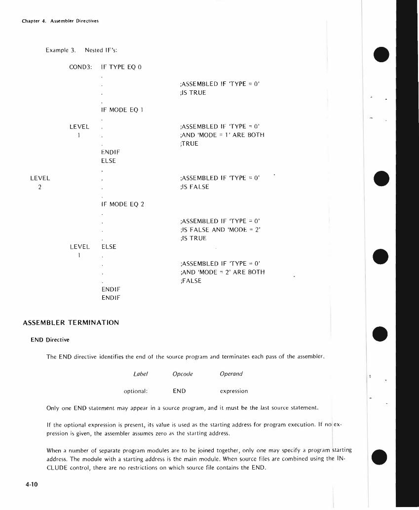
Chapter 4 Assembler Directives
-I
Example 3 Nested IFs
COND3 IF TYPE EO 0 bull ASSEMBLED IF TYPE = 0
IS TRUE
IF MODE EO 1
LEVEL ASSEMBLED IF TYPE = 0 AND MODE = l ARE BOTH
TRUE ENDIF ELSE
LEVEL ASSEMBLED IF TYPE 0
2 IS FALSE bull IF MODE EO 2
ASSEMBLED IF TYPE = 0 IS FALSE AND MODE = 2 IS TRUE
LEVEL ELSE
ASSEMBLED IF TYPE = 0 AND MODE = 2 ARE BOTH bullFALSE
ENDIF ENDIF
ASSEMBLER TERMINATION
END Directive bullThe END directive identifies the end of the source program and terminates each pass of the assembler
Label Opcode Operand
optional END expression
Only one END statement may appear in a source program and it must be the last source statement
If the optional expression is present its value is used as the starting address for program execution If no exmiddot pression is given the assembler assumes zero as the starting address
When a number of separate program modules are to be joined together only one may specify a program starting address The module with a starting address is the main module When source files are combined using the INshy
CLUDE control there are no restrictions on which source file contains the END bull 4-10
Chapter 4 Assembler Directives
bull END-OF-TAPE INDICATION
The EOT directive allows you to specify the physical end of paper tape to simplify assembly of multiple-tape source
programs
EOT Directive
Label Opcode Operand
optional EOT
When EOT is recognized by the assembler the message NEXT TAPE is sent to the console and the assembler pauses
After the next tape is loaded a space bar character rece ived at the console signals continuation of the assembly
bull Data in the operand field causes an error
LOCATION COUNTER CONTROL AND RELOCATION
All the directives discussed in the remainder of this chapter relate directly to program relocation except for the
ASEG and ORG directives These directives are described first for the convenience of readers who do not use the
relocation feature
bull Location Counter Control (Non-Relocatable Mode)
When you elect not to use the relocation feature an assembler default generates an ASEG directive for you The
ASEG directive specifies that the program is to be assembled in the non-relocatable mode and establishes a
location cou nter for the assembly
bull The location counter performs the same function for the assembler as the program counter performs during
execution It tells the assembler the next memory location available for instruction or data assembly
Initially the location counter is set to zero The location counter can be altered by the ORG (origin) directive
ORG Directive
The ORG directive sets the location counter to the value specified by the operand expression
Label Opcode Operand
optional ORG expression
The location counter is set to the value of the operand expression Assembly-time evaluation of ORG expressions
bull always yields a modulo 64K address Thus the expression always yields an address in the range 0 through
65535 Any symbol in the expression must be previously defined The next machine instruction or data item is
assembled at the specified address
4-11
Chapter 4 Assembler Directives
If no ORG directive is included before the first instruction or data byte in your program assembly begins at location zero
Your program can include any number of ORG directives Multiple ORGs need not specify addresses in ascending sequence but if you fail to do so you may instruct the assembler to write over some previously assembled portion of the program
If the optional label is present it is assigned the current value of the location counter before it is updated by the ORG directive
Example
Assume that the current value of the location counter is OFH (decimal 15) when the following ORG directive is encountered
PAG1 ORG OFFH ORG ASSEMBLER TO LOCATION
OFFH (decimal 225)
The symbol PAGI is assigned the address OFH The next instruction or data byte is assembled at location OFFH
Introduction to Relocatability
A major feature of this assembler is its system for creating relocatable object code modules Support for this new
feature includes a number of new directives for the assembler and three new programs included in ISIS-II The three new programs - LIB LINK and LOCATE _ arc described in the ISIS-Ii System Users Guide The new
assembler directives are described later in this chapter
Relocatability allows the programmer to code programs or sections of programs without worrying about the final arrangement of the object code in memory This offers developers of microcomputer systems major adshyvantages in two areas memory management and modular program development
Memory Management
When developing testing and debugging a system on your Intellec microcomputer development system your only concern with locating a program is that it doesnt overlap the resident routines of ISIS-II Because the Intellec system has 32K 48K or 64K of random access memory the location of your future program is not a great concern_ However the program you arc developing will almost certainly use some mix of random access memory (RAM) readmiddotonly memory (ROM) andor programmable read-only memory (PROM) Therefore the location of your program affects both cost dnd performance in your application The relocatability feature allows
you to develop test and debug your program on the Intellec development system and then simply relocate the object code to suit your application
The relocatability feature also has a major advantage at assembly-time often large programs with many symbols cannot be assembled because of limited work space for the symbol table Such a program can be divided into a
number of modules that can be assembled separately and then linked together to form a single object program
bull
bull
bull
bull
bull 4-12
Chapter 4 Assembler Directives
Modular Program Development
Although relocatability may seem to be a formidable term what it really means is that you can subdivide a
complex program into a number of smaller simpler programs This concept is best illustrated through the use of an example Assume thai a microcomputer program is to control the spark advance on an automobile engine This requires the program to sample the ambient air temperature engine air intake temperature coolant temperashyture manifold vacuum idle sensor and throttle sensor
Let us examine the approaches two different programmers might take to solve this problem Both programmers
want to calculate the degree of spark advance or retardation that provides the best fuel economy with the lowest
emissions Programmer A codes a single program that senses all inputs and calculates the correct spark advance
Programmer B uses a modular approach and codes separate programs for each input plus one program to calculate
spark advance
Although Programmer A avoids the need to learn to use the relocatability feature the modular approach used by Programmer B has a number of advantages you should consider
bull Simplified Program Development
It is generally easier to code test and debug several simple programs than one complex program
bull Sharing the Programming Task
If Programmer B finds that he is falling behind schedule he can assign one or more of his subshy
programs to another programmer Because of his single program concept Programmer A will
probably have to complete the program himself
bull Ease of Testing
Programmer B can lest and debug most of his modules as soon as they arc assembled Programmer
A must lest his program as a whol~ Notice that Programmer B has an extra advantage if the
sensors are being developed at the same lime as the program If one oflhe sensors is behind
schedule Programmer B can continue developing and testing programs for the sensors that arc
ready Because Programmer A cannot test his program until all the sensors are developed his
testing schedule is dependent on events beyond his control
bull Programming Changes
Given the nature of automotive design it is reasonable to expect some changes Juring system development If a change to one of the sensors requires a programming change Programmer A must search through his entire program to find and alter the coding for that sensor Then he must retest the entire program to be certain that those changes do not affect any of the other sensors
By contrast Programmer B need be concerned only with the module for that one sensor This
advantage continues throughout the life of the program
4middot13
Chapter 4 Assembler Directives
DIRECTIVES USED FOR RELOCATION
Several directives have been added to the assembler to support the relocation feature These fdll into the general
categories of location counter control and program linkage
Location Counter Control (Relocatable Programs)
Relocatable programs or program modules may use three locdtion counters The ASEG DSEG and CSEG
directive~ specify which location counter is to be used
The ASEG directive specifies dn dbsolute code segment Even in a relocdtable program module you may want to assign certain code segments to specific addresses For example restart routines invoked by the RST instrucshytion require specific addresses
The CSEG directive specifies a relocatable code segment In general the CSEG location counter is used for porshytions of the program that are to be in some form of read-only memory such as mdchine instructions and proshygram constants
The DSEG location counter specifies a relocdtdble data segment This location counter is used for program
elements that must be located in random access memory
These directives allow you to control program segmentation at assembly time The LOCATE program described in the ISIS-II System Users Guide gives you control over program segment location Therefore the guidelines given dbove are only generdl since they can be overridden by the LOCATE program
Regardless of how many times the ASEG CSEG and DSEG directives appear in your program the assembler produces a single contiguous module Th is module comprises four segments code data stack and memory The LINK and LOCATE programs are used to combine segments from individual modules and relocate them in
memory These programs are explained in the ISIS-II System Users Guide
ASEG Directive
ASEG directs the assembler to use the location counter for the dbsolute program segment
Label Opcode Operand
optional ASEG
Operands are not permitted with the ASEG directive
All instructions and data following the ASEG directive are dssembled in the absolute mode The ASEG directive
remains in effect until d CSEG or DSEG directive is encountered
The ASEG location counter has an initial value of zero The ORG directive can be used to dssign a new value to the ASEG location counter
bull
bull
bull
bull
bull 4-14
Chapter 4 Assembler Directives
When begins the assembler assurres the ASEG directive to be in effect Therefore a CSEG or DSEG
must the first instruction or data definition in a relocatable module If neither of these directives
appears in the program the entire program is assembltd in absolute mode and can be executed immediately
after without using the LINK or LOCATE programs
CSEG Directive
CSEG directs the assembler to assemble instructions and data in the relocatable mode the code
segment location counter
Label Opcode Operand
blank optional CSEG PAGE
INPAGE
When a program contains multiple CSEG all CSEG directives the program must specify
The operand of a CSEG directive has no effect on the current assembly but is stored with code to be to the LINK and LOCATE programs programs are described in the ISIS-II
The LOCATE program uses this information to determine relocation boundaries when it
joins this code segment to code segments from other programs The of the operand is as follows
bull blank This code segment may be relocated to the next available byte boundary
bull PAGE This code segment must when relocated boundaries
occur in multiples of 256 512 etc)
INPAGE -- This code segment must fit within a single page when relocated
The CSEG directive remains in effect until an ASEG or DSEG directive is encountered_
The code segment location counter has an initial value of zero The ORG directive can be used to a new
val ue to the CSEG location counter
DSEG Directive
DSEG directs the assembler to assemble subsequent instructions and data in the relocatable mode using the data
segment location counter
Label Operand
blank DSEG PAGE
INPAGE
When multiple DSEG directives appear in a program they must all specify the same throughout the
program The operands for the DSEG directive have the same meaning as for the CSEG directive except that
they apply to the data segment
4-15
Chapter 4 Assembler Directives
There is no interaction between the operands specified for the DSEG and CSEG directives Thus a code segment
can be byte relocatable while the data segment is page relocatable bull The DSEG directive remaim in effect IJntil an ASEG or CSEG directive is encountered
The data segment location counter has an initial value of zero The ORG directive can be used to assign a new
value to the DSEG location counter
ORG Directive (Relocalable Mode)
The ORG directive can be used to alter the value of the location counter presently in use
Label Opcode Operand
optional ORG expression bullThere are three location counters but only one location counter is in use at any given point in the program
Which one depends on whether the ASEG CSEG or DSEG directive is in effect
Any symbol used in the operand expression must have been previously defined An exception causes phase
errors for all labels that follow the ORG and a label error if the undefined error is defined later
When the ORG directive appears in a relocatable program segment the value of its operand expression must be
either absolute or relocatable within the current segment Thus if the ORG directive appears within a data segshy
ment the value of its expression must be relocatable within the data segment An error occurs if the expression bullevaluates to an address in the code segment
If the optional label is present it is assigned the current value of the location counter presently in use before
the ORG directive is executed
Program Linkage Directives
Modular programming and the relocation feature enable you to assemble and test a number of separate programs bullthat are to be joined together and executed as a single program Eventually it becomes necessary for these
separate programs to communicate information among themselves Establishing such communication is the
fu net ion of the program I inkage directives
A program may share its data addresses and instruction addresses with other programs Only items having an
entry in the symbol table can be shared with other programs therefore the item must be assigned a name or a
label when it is defined in the program I tems to be shared with other programs must be declared in a PUBLIC directive
Your program can directly access data or instructions defined in another program if you know the actual
address of the item but this is unlikely when both programs use relocation Your program can also gain access
to data or instructions declared as PUBLIC in other programs Notice however that the assembler normally
4-16
Chapter 4 Assembler Directives
flags as an error ltlny reference to ltl nltlme or lltlbel thltlt hltlS not been defined in your program To ltlvoid this
you must provide the assembler with ltl list of items used in your program but defined in some other program
These items must be declltlred in an EXTRN directive
The two remaining program linkage directives NAME and STKLN are individually explained later in this chltlpter
PUBLIC Directive
The PUBLIC directive makes each of the symbols listed in the operand field available for access by other programs
Label Opcode Operands
optionltll PUBLIC name-list
Each item in the operand name-list must be the name or label assigned to data or an instruction elsewhere in this program When multiple names appear in the list they must be seplttrated by commas Each nltlme may be declared PUBLIC only once in a program module Reserved words and externltll symbols (see the EXTRN directive below) cannot be declared to be PUBLIC symbols
PUBLIC directives may appear anywhere within a program module
if an item in the operand name-list has no corresponding entry in the symbol table (implying that it is undeshy
fined) it is flagged as an error
Example
PUBLIC SINCOSTANSQRT
EXTRN Directive
The EXTRN directive provides the assembler with a list of symbols referenced in this program but defined in a
different program Because of this the assembler establishes linkage to the other program and does not flag the
undefi ned references as errors
Label Opcode Operands
optional EXTRN name-list
Each item in the name-list identifies a symbol that may be referenced in this program but is defined in another program When multiple items appear in the list they must be separated by commas
If a symbol in the operand name-list is also defined in this program by the user or is a reserved symbol the effect
is the same as defining the same symbol more than once in a program The assembler flags this error
EXTRN directives may appear anywhere within a program module
A symbol may be declared to be external only once in a program module Symbols declared to be PUBLIC cannot also be declared to be EXTRN symbols
4-17
Chapter 4 Assembler Directives
If you omit a symbol from the name--list but reference it in the program the symbol is undefined The assembler
flags this error You may include symbols in the operand name--list that are not referenced in the program withshy bullout causing an error
Example
EXTRN ENTRYADDRTNBEGIN
NAME Directive
The NAME directive assigns a name to the object module generated by this assembly
Label Opcode Operand
optional NAME module-name bull The NAME directive requires the presence of a module-name in the operand field This name must conform to
the rules for defining symbols
Module names are necessary so that you can refer to a module and specify the proper sequence of modules
when a number of modules are to be bound together
The NAME directive must precede the first data or instruction coding in the source program but may follow
comments and control lines bullIf the NAME directive is missing from the program the assembler supplies a default NAME directive with the module-name MODULE This will cause an error if you attempt to bind together several object program modules and more than one has the name MODULE Also if you make an error coding the NAME directive the default name MODULE is assigned
The module - name assigned by the NAME directive appears as part of the page heading in the assembly listing
Example bullNAME MAIN
STKLN Directive
Regardless of the number of object program modules you may bind together only one stack is generated The
STKLN directive allows you to specify the number of bytes to be reserved for the stack for each module
Label Opcode Operand
optional STKLN expression
The operand expression must evaluate to a number which will be used as the maximum size of the stack bull 4middot18
Chapter 4 Assembler Directives
bull When the STKLN directive is omitted the provides a default STKLN of zero This is useful when multiple programs are bound only one stack will be so only one program module need
the stack size However you should provide a STKLN if your module is to be tested separately and uses the stack
If your program includes more than one STKLN directive the last value is retained
STKLN 100
STACI( and MEMORY Reserved Words
bull The reserved words STACK and MEMORY are not directives but are of interest to programmers using the relocation feature These reserved words are external references whose addresses are supplied by the LOCATE
program
STACK is the reference to the stack address You need this address to initialize the stack
pointer register Also you can base data structures on th is address symbolic references such as 5T ACK+1
etc
bull MEMORY is the symbolic reference to the first byte of unused memory the end of your program you can base data structures on this address symbolic such as MEMORY MEMORY+I etc
Programming Testing Rclocatable Modules
The ability to test individual program modules is a major of modular programming However many program modules are not self-sufficient and require some modification before they can be tested The following is a discussion of some of the more Common modifications that may be required
bull Initialization Routines
In most complete programs a number of or initialization are performed when execution first begins If the program module you are relies on initialization assigned to a different
you must duplicate those procedures in the module to be tested however that you can link any number of modules together for
One of the most important initialization is to set the stack The LOCATE program determines the origin of the stack
Your program should include the instruction to initialize the stack
LXI
bull 4middot19
Chapler 4 Assembler Direclives
InputOutput
When testing program modules it is likely that some input or output procedures appear in other modules Your bull program must simulate any of these procedures it needs to operate Since your Intellec development system
probably has considerably more random access memory than you need to test a program module you may be
able to simulate input and output data right in memory The LOCATE program supplies an address for the
reserved word MEMORY this is the address of the first byte of unused memory past the end of your program
You can access this memory using the symbolic reference MEMORY MEMORY+l and so on This memory can be used for storing test data or even for a program that generates test data
Remove Coding Used for Testing
After testing your program be certain to remove any code you inserted for testing In particular make certain that only one module in the complete program initializes the stack pointer bull
bull
bull
bull 4-20
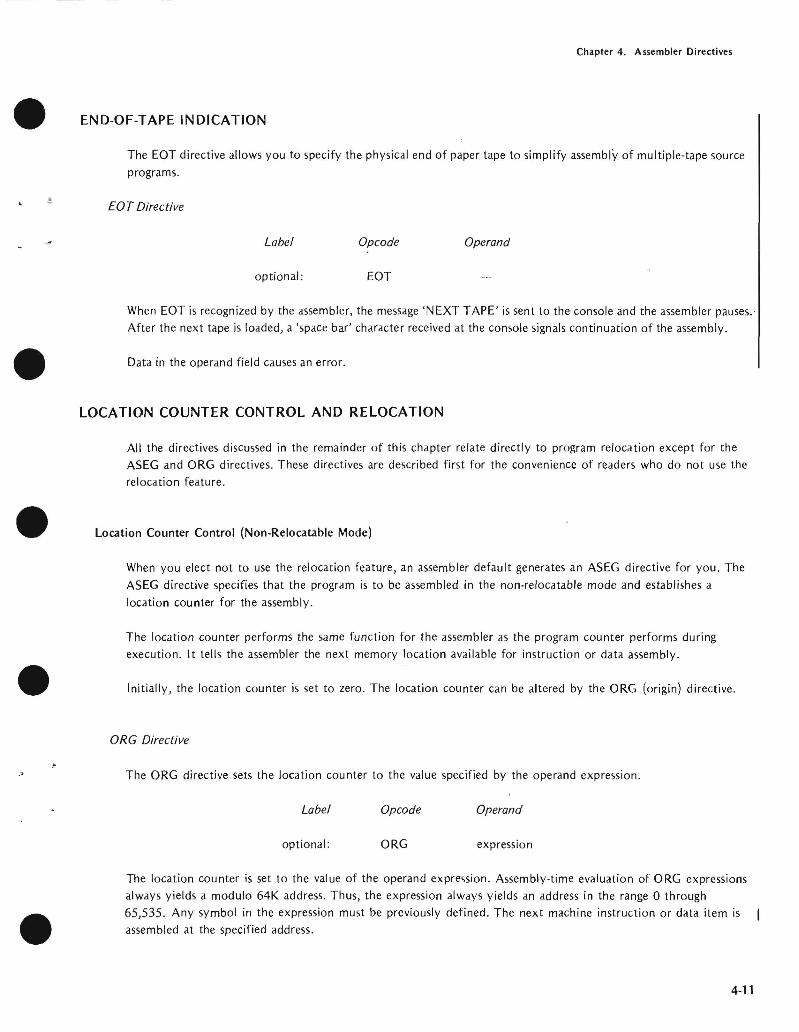
Chapter 4 Assembler Directives
bull END-OF-TAPE INDICATION
The EOT directive allows you to specify the physical end of paper tape to simplify assembly of multiple-tape source
programs
EOT Directive
Label Opcode Operand
optional EOT
When EOT is recognized by the assembler the message NEXT TAPE is sent to the console and the assembler pauses
After the next tape is loaded a space bar character rece ived at the console signals continuation of the assembly
bull Data in the operand field causes an error
LOCATION COUNTER CONTROL AND RELOCATION
All the directives discussed in the remainder of this chapter relate directly to program relocation except for the
ASEG and ORG directives These directives are described first for the convenience of readers who do not use the
relocation feature
bull Location Counter Control (Non-Relocatable Mode)
When you elect not to use the relocation feature an assembler default generates an ASEG directive for you The
ASEG directive specifies that the program is to be assembled in the non-relocatable mode and establishes a
location cou nter for the assembly
bull The location counter performs the same function for the assembler as the program counter performs during
execution It tells the assembler the next memory location available for instruction or data assembly
Initially the location counter is set to zero The location counter can be altered by the ORG (origin) directive
ORG Directive
The ORG directive sets the location counter to the value specified by the operand expression
Label Opcode Operand
optional ORG expression
The location counter is set to the value of the operand expression Assembly-time evaluation of ORG expressions
bull always yields a modulo 64K address Thus the expression always yields an address in the range 0 through
65535 Any symbol in the expression must be previously defined The next machine instruction or data item is
assembled at the specified address
4-11
Chapter 4 Assembler Directives
If no ORG directive is included before the first instruction or data byte in your program assembly begins at location zero
Your program can include any number of ORG directives Multiple ORGs need not specify addresses in ascending sequence but if you fail to do so you may instruct the assembler to write over some previously assembled portion of the program
If the optional label is present it is assigned the current value of the location counter before it is updated by the ORG directive
Example
Assume that the current value of the location counter is OFH (decimal 15) when the following ORG directive is encountered
PAG1 ORG OFFH ORG ASSEMBLER TO LOCATION
OFFH (decimal 225)
The symbol PAGI is assigned the address OFH The next instruction or data byte is assembled at location OFFH
Introduction to Relocatability
A major feature of this assembler is its system for creating relocatable object code modules Support for this new
feature includes a number of new directives for the assembler and three new programs included in ISIS-II The three new programs - LIB LINK and LOCATE _ arc described in the ISIS-Ii System Users Guide The new
assembler directives are described later in this chapter
Relocatability allows the programmer to code programs or sections of programs without worrying about the final arrangement of the object code in memory This offers developers of microcomputer systems major adshyvantages in two areas memory management and modular program development
Memory Management
When developing testing and debugging a system on your Intellec microcomputer development system your only concern with locating a program is that it doesnt overlap the resident routines of ISIS-II Because the Intellec system has 32K 48K or 64K of random access memory the location of your future program is not a great concern_ However the program you arc developing will almost certainly use some mix of random access memory (RAM) readmiddotonly memory (ROM) andor programmable read-only memory (PROM) Therefore the location of your program affects both cost dnd performance in your application The relocatability feature allows
you to develop test and debug your program on the Intellec development system and then simply relocate the object code to suit your application
The relocatability feature also has a major advantage at assembly-time often large programs with many symbols cannot be assembled because of limited work space for the symbol table Such a program can be divided into a
number of modules that can be assembled separately and then linked together to form a single object program
bull
bull
bull
bull
bull 4-12
Chapter 4 Assembler Directives
Modular Program Development
Although relocatability may seem to be a formidable term what it really means is that you can subdivide a
complex program into a number of smaller simpler programs This concept is best illustrated through the use of an example Assume thai a microcomputer program is to control the spark advance on an automobile engine This requires the program to sample the ambient air temperature engine air intake temperature coolant temperashyture manifold vacuum idle sensor and throttle sensor
Let us examine the approaches two different programmers might take to solve this problem Both programmers
want to calculate the degree of spark advance or retardation that provides the best fuel economy with the lowest
emissions Programmer A codes a single program that senses all inputs and calculates the correct spark advance
Programmer B uses a modular approach and codes separate programs for each input plus one program to calculate
spark advance
Although Programmer A avoids the need to learn to use the relocatability feature the modular approach used by Programmer B has a number of advantages you should consider
bull Simplified Program Development
It is generally easier to code test and debug several simple programs than one complex program
bull Sharing the Programming Task
If Programmer B finds that he is falling behind schedule he can assign one or more of his subshy
programs to another programmer Because of his single program concept Programmer A will
probably have to complete the program himself
bull Ease of Testing
Programmer B can lest and debug most of his modules as soon as they arc assembled Programmer
A must lest his program as a whol~ Notice that Programmer B has an extra advantage if the
sensors are being developed at the same lime as the program If one oflhe sensors is behind
schedule Programmer B can continue developing and testing programs for the sensors that arc
ready Because Programmer A cannot test his program until all the sensors are developed his
testing schedule is dependent on events beyond his control
bull Programming Changes
Given the nature of automotive design it is reasonable to expect some changes Juring system development If a change to one of the sensors requires a programming change Programmer A must search through his entire program to find and alter the coding for that sensor Then he must retest the entire program to be certain that those changes do not affect any of the other sensors
By contrast Programmer B need be concerned only with the module for that one sensor This
advantage continues throughout the life of the program
4middot13
Chapter 4 Assembler Directives
DIRECTIVES USED FOR RELOCATION
Several directives have been added to the assembler to support the relocation feature These fdll into the general
categories of location counter control and program linkage
Location Counter Control (Relocatable Programs)
Relocatable programs or program modules may use three locdtion counters The ASEG DSEG and CSEG
directive~ specify which location counter is to be used
The ASEG directive specifies dn dbsolute code segment Even in a relocdtable program module you may want to assign certain code segments to specific addresses For example restart routines invoked by the RST instrucshytion require specific addresses
The CSEG directive specifies a relocatable code segment In general the CSEG location counter is used for porshytions of the program that are to be in some form of read-only memory such as mdchine instructions and proshygram constants
The DSEG location counter specifies a relocdtdble data segment This location counter is used for program
elements that must be located in random access memory
These directives allow you to control program segmentation at assembly time The LOCATE program described in the ISIS-II System Users Guide gives you control over program segment location Therefore the guidelines given dbove are only generdl since they can be overridden by the LOCATE program
Regardless of how many times the ASEG CSEG and DSEG directives appear in your program the assembler produces a single contiguous module Th is module comprises four segments code data stack and memory The LINK and LOCATE programs are used to combine segments from individual modules and relocate them in
memory These programs are explained in the ISIS-II System Users Guide
ASEG Directive
ASEG directs the assembler to use the location counter for the dbsolute program segment
Label Opcode Operand
optional ASEG
Operands are not permitted with the ASEG directive
All instructions and data following the ASEG directive are dssembled in the absolute mode The ASEG directive
remains in effect until d CSEG or DSEG directive is encountered
The ASEG location counter has an initial value of zero The ORG directive can be used to dssign a new value to the ASEG location counter
bull
bull
bull
bull
bull 4-14
Chapter 4 Assembler Directives
When begins the assembler assurres the ASEG directive to be in effect Therefore a CSEG or DSEG
must the first instruction or data definition in a relocatable module If neither of these directives
appears in the program the entire program is assembltd in absolute mode and can be executed immediately
after without using the LINK or LOCATE programs
CSEG Directive
CSEG directs the assembler to assemble instructions and data in the relocatable mode the code
segment location counter
Label Opcode Operand
blank optional CSEG PAGE
INPAGE
When a program contains multiple CSEG all CSEG directives the program must specify
The operand of a CSEG directive has no effect on the current assembly but is stored with code to be to the LINK and LOCATE programs programs are described in the ISIS-II
The LOCATE program uses this information to determine relocation boundaries when it
joins this code segment to code segments from other programs The of the operand is as follows
bull blank This code segment may be relocated to the next available byte boundary
bull PAGE This code segment must when relocated boundaries
occur in multiples of 256 512 etc)
INPAGE -- This code segment must fit within a single page when relocated
The CSEG directive remains in effect until an ASEG or DSEG directive is encountered_
The code segment location counter has an initial value of zero The ORG directive can be used to a new
val ue to the CSEG location counter
DSEG Directive
DSEG directs the assembler to assemble subsequent instructions and data in the relocatable mode using the data
segment location counter
Label Operand
blank DSEG PAGE
INPAGE
When multiple DSEG directives appear in a program they must all specify the same throughout the
program The operands for the DSEG directive have the same meaning as for the CSEG directive except that
they apply to the data segment
4-15
Chapter 4 Assembler Directives
There is no interaction between the operands specified for the DSEG and CSEG directives Thus a code segment
can be byte relocatable while the data segment is page relocatable bull The DSEG directive remaim in effect IJntil an ASEG or CSEG directive is encountered
The data segment location counter has an initial value of zero The ORG directive can be used to assign a new
value to the DSEG location counter
ORG Directive (Relocalable Mode)
The ORG directive can be used to alter the value of the location counter presently in use
Label Opcode Operand
optional ORG expression bullThere are three location counters but only one location counter is in use at any given point in the program
Which one depends on whether the ASEG CSEG or DSEG directive is in effect
Any symbol used in the operand expression must have been previously defined An exception causes phase
errors for all labels that follow the ORG and a label error if the undefined error is defined later
When the ORG directive appears in a relocatable program segment the value of its operand expression must be
either absolute or relocatable within the current segment Thus if the ORG directive appears within a data segshy
ment the value of its expression must be relocatable within the data segment An error occurs if the expression bullevaluates to an address in the code segment
If the optional label is present it is assigned the current value of the location counter presently in use before
the ORG directive is executed
Program Linkage Directives
Modular programming and the relocation feature enable you to assemble and test a number of separate programs bullthat are to be joined together and executed as a single program Eventually it becomes necessary for these
separate programs to communicate information among themselves Establishing such communication is the
fu net ion of the program I inkage directives
A program may share its data addresses and instruction addresses with other programs Only items having an
entry in the symbol table can be shared with other programs therefore the item must be assigned a name or a
label when it is defined in the program I tems to be shared with other programs must be declared in a PUBLIC directive
Your program can directly access data or instructions defined in another program if you know the actual
address of the item but this is unlikely when both programs use relocation Your program can also gain access
to data or instructions declared as PUBLIC in other programs Notice however that the assembler normally
4-16
Chapter 4 Assembler Directives
flags as an error ltlny reference to ltl nltlme or lltlbel thltlt hltlS not been defined in your program To ltlvoid this
you must provide the assembler with ltl list of items used in your program but defined in some other program
These items must be declltlred in an EXTRN directive
The two remaining program linkage directives NAME and STKLN are individually explained later in this chltlpter
PUBLIC Directive
The PUBLIC directive makes each of the symbols listed in the operand field available for access by other programs
Label Opcode Operands
optionltll PUBLIC name-list
Each item in the operand name-list must be the name or label assigned to data or an instruction elsewhere in this program When multiple names appear in the list they must be seplttrated by commas Each nltlme may be declared PUBLIC only once in a program module Reserved words and externltll symbols (see the EXTRN directive below) cannot be declared to be PUBLIC symbols
PUBLIC directives may appear anywhere within a program module
if an item in the operand name-list has no corresponding entry in the symbol table (implying that it is undeshy
fined) it is flagged as an error
Example
PUBLIC SINCOSTANSQRT
EXTRN Directive
The EXTRN directive provides the assembler with a list of symbols referenced in this program but defined in a
different program Because of this the assembler establishes linkage to the other program and does not flag the
undefi ned references as errors
Label Opcode Operands
optional EXTRN name-list
Each item in the name-list identifies a symbol that may be referenced in this program but is defined in another program When multiple items appear in the list they must be separated by commas
If a symbol in the operand name-list is also defined in this program by the user or is a reserved symbol the effect
is the same as defining the same symbol more than once in a program The assembler flags this error
EXTRN directives may appear anywhere within a program module
A symbol may be declared to be external only once in a program module Symbols declared to be PUBLIC cannot also be declared to be EXTRN symbols
4-17
Chapter 4 Assembler Directives
If you omit a symbol from the name--list but reference it in the program the symbol is undefined The assembler
flags this error You may include symbols in the operand name--list that are not referenced in the program withshy bullout causing an error
Example
EXTRN ENTRYADDRTNBEGIN
NAME Directive
The NAME directive assigns a name to the object module generated by this assembly
Label Opcode Operand
optional NAME module-name bull The NAME directive requires the presence of a module-name in the operand field This name must conform to
the rules for defining symbols
Module names are necessary so that you can refer to a module and specify the proper sequence of modules
when a number of modules are to be bound together
The NAME directive must precede the first data or instruction coding in the source program but may follow
comments and control lines bullIf the NAME directive is missing from the program the assembler supplies a default NAME directive with the module-name MODULE This will cause an error if you attempt to bind together several object program modules and more than one has the name MODULE Also if you make an error coding the NAME directive the default name MODULE is assigned
The module - name assigned by the NAME directive appears as part of the page heading in the assembly listing
Example bullNAME MAIN
STKLN Directive
Regardless of the number of object program modules you may bind together only one stack is generated The
STKLN directive allows you to specify the number of bytes to be reserved for the stack for each module
Label Opcode Operand
optional STKLN expression
The operand expression must evaluate to a number which will be used as the maximum size of the stack bull 4middot18
Chapter 4 Assembler Directives
bull When the STKLN directive is omitted the provides a default STKLN of zero This is useful when multiple programs are bound only one stack will be so only one program module need
the stack size However you should provide a STKLN if your module is to be tested separately and uses the stack
If your program includes more than one STKLN directive the last value is retained
STKLN 100
STACI( and MEMORY Reserved Words
bull The reserved words STACK and MEMORY are not directives but are of interest to programmers using the relocation feature These reserved words are external references whose addresses are supplied by the LOCATE
program
STACK is the reference to the stack address You need this address to initialize the stack
pointer register Also you can base data structures on th is address symbolic references such as 5T ACK+1
etc
bull MEMORY is the symbolic reference to the first byte of unused memory the end of your program you can base data structures on this address symbolic such as MEMORY MEMORY+I etc
Programming Testing Rclocatable Modules
The ability to test individual program modules is a major of modular programming However many program modules are not self-sufficient and require some modification before they can be tested The following is a discussion of some of the more Common modifications that may be required
bull Initialization Routines
In most complete programs a number of or initialization are performed when execution first begins If the program module you are relies on initialization assigned to a different
you must duplicate those procedures in the module to be tested however that you can link any number of modules together for
One of the most important initialization is to set the stack The LOCATE program determines the origin of the stack
Your program should include the instruction to initialize the stack
LXI
bull 4middot19
Chapler 4 Assembler Direclives
InputOutput
When testing program modules it is likely that some input or output procedures appear in other modules Your bull program must simulate any of these procedures it needs to operate Since your Intellec development system
probably has considerably more random access memory than you need to test a program module you may be
able to simulate input and output data right in memory The LOCATE program supplies an address for the
reserved word MEMORY this is the address of the first byte of unused memory past the end of your program
You can access this memory using the symbolic reference MEMORY MEMORY+l and so on This memory can be used for storing test data or even for a program that generates test data
Remove Coding Used for Testing
After testing your program be certain to remove any code you inserted for testing In particular make certain that only one module in the complete program initializes the stack pointer bull
bull
bull
bull 4-20
Chapter 4 Assembler Directives
bull When the STKLN directive is omitted the provides a default STKLN of zero This is useful when multiple programs are bound only one stack will be so only one program module need
the stack size However you should provide a STKLN if your module is to be tested separately and uses the stack
If your program includes more than one STKLN directive the last value is retained
STKLN 100
STACI( and MEMORY Reserved Words
bull The reserved words STACK and MEMORY are not directives but are of interest to programmers using the relocation feature These reserved words are external references whose addresses are supplied by the LOCATE
program
STACK is the reference to the stack address You need this address to initialize the stack
pointer register Also you can base data structures on th is address symbolic references such as 5T ACK+1
etc
bull MEMORY is the symbolic reference to the first byte of unused memory the end of your program you can base data structures on this address symbolic such as MEMORY MEMORY+I etc
Programming Testing Rclocatable Modules
The ability to test individual program modules is a major of modular programming However many program modules are not self-sufficient and require some modification before they can be tested The following is a discussion of some of the more Common modifications that may be required
bull Initialization Routines
In most complete programs a number of or initialization are performed when execution first begins If the program module you are relies on initialization assigned to a different
you must duplicate those procedures in the module to be tested however that you can link any number of modules together for
One of the most important initialization is to set the stack The LOCATE program determines the origin of the stack
Your program should include the instruction to initialize the stack
LXI
bull 4middot19
Chapler 4 Assembler Direclives
InputOutput
When testing program modules it is likely that some input or output procedures appear in other modules Your bull program must simulate any of these procedures it needs to operate Since your Intellec development system
probably has considerably more random access memory than you need to test a program module you may be
able to simulate input and output data right in memory The LOCATE program supplies an address for the
reserved word MEMORY this is the address of the first byte of unused memory past the end of your program
You can access this memory using the symbolic reference MEMORY MEMORY+l and so on This memory can be used for storing test data or even for a program that generates test data
Remove Coding Used for Testing
After testing your program be certain to remove any code you inserted for testing In particular make certain that only one module in the complete program initializes the stack pointer bull
bull
bull
bull 4-20