Embed Size (px)
Citation preview
© 2017 Symantec Corporation 1 of 44 Updated 5 Jun 2017
Symantec Corporation
Security Analytics S500 Appliances Models: SA-S500-10-CM, SA-S500-20-FA, SA-S500-30-FA, SA-S500-40-FA Hardware Versions: 090-03645, 080-03938, 090-03646, 080-03939, 090-03648, 080-03940, 090-03649, and 080-03941 FIPS Security Kit Version: HW-KIT-FIPS-500 Firmware Version: 7.2.3
FIPS 140-2 Non-Proprietary Security Policy FIPS 140-2 Security Level: 2 Document Version: 0.8
© 2017 Symantec Corporation 2 of 44 Updated 5 Jun 2017
COPYRIGHT NOTICE
© 2017 Symantec Corporation All rights reserved. BLUE COAT, PROXYSG, PACKETSHAPER, CACHEFLOW,
INTELLIGENCECENTER, CACHEOS, CACHEPULSE, CROSSBEAM, K9, DRTR, MACH5, PACKETWISE,
POLICYCENTER, PROXYAV, PROXYCLIENT, SGOS, WEBPULSE, SOLERA NETWORKS, DEEPSEE, DS
APPLIANCE, SEE EVERYTHING. KNOW EVERYTHING., SECURITY EMPOWERS BUSINESS, BLUETOUCH, the
Blue Coat shield, K9, and Solera Networks logos and other Symantec logos are registered
trademarks or trademarks of Symantec Corporation or its affiliates in the U.S. and certain other countries. This list may
not be complete, and the absence of a trademark from this list does not mean it is not a trademark of Symantec or that
Symantec has stopped using the trademark. All other trademarks mentioned in this document owned by third parties
are the property of their respective owners. This document is for informational purposes only.
SYMANTEC MAKES NO WARRANTIES, EXPRESS, IMPLIED, OR STATUTORY, AS TO THE INFORMATION IN THIS DOCUMENT. SYMANTEC PRODUCTS, TECHNICAL SERVICES, AND ANY OTHER TECHNICAL DATA REFERENCED IN THIS DOCUMENT ARE SUBJECT TO U.S. EXPORT CONTROL AND SANCTIONS LAWS, REGULATIONS AND REQUIREMENTS, AND MAY BE SUBJECT TO EXPORT OR IMPORT REGULATIONS IN OTHER COUNTRIES. YOU AGREE TO COMPLY STRICTLY WITH THESE LAWS, REGULATIONS AND REQUIREMENTS, AND ACKNOWLEDGE THAT YOU HAVE THE RESPONSIBILITY TO OBTAIN ANY LICENSES, PERMITS OR OTHER APPROVALS THAT MAY BE REQUIRED IN ORDER TO EXPORT, RE-EXPORT, TRANSFER IN COUNTRY OR IMPORT AFTER DELIVERY TO YOU.
Americas: Rest of the World:
Symantec Corporation 350 Ellis Street Mountain View, CA 94043
This document may be freely reproduced and distributed whole and intact including this copyright notice.
© 2017 Symantec Corporation 3 of 44 Updated 5 Jun 2017
Table of Contents 1. INTRODUCTION .................................................................................................................. 5
1.1 PURPOSE ...................................................................................................................... 5 1.2 REFERENCES ................................................................................................................ 5 1.3 DOCUMENT ORGANIZATION ............................................................................................. 5
2. SECURITY ANALYTICS S500 APPLIANCE ........................................................................ 6 2.1 OVERVIEW .................................................................................................................... 6 2.2 MODULE SPECIFICATION ................................................................................................. 8 2.3 MODULE INTERFACES ..................................................................................................... 8
2.3.1 SA-S500-10-CM/20-FA/30-FA/40-FA Front Panel ............................................. 9 2.3.2 SA-S500-10-CM Rear Panel ........................................................................... 10 2.3.3 SA-S500-20-FA Rear Panel ............................................................................ 12 2.3.4 SA-S500-30-FA Rear Panel ............................................................................ 13 2.3.5 SA-S500-40-FA Rear Panel ............................................................................ 14
2.4 ROLES AND SERVICES .................................................................................................. 15 2.4.1 Crypto-Officer Role ......................................................................................... 16 2.4.2 User Role ....................................................................................................... 19 2.4.3 Authentication Mechanism .............................................................................. 21
2.5 PHYSICAL SECURITY .................................................................................................... 25 2.6 NON-MODIFIABLE OPERATIONAL ENVIRONMENT .............................................................. 25 2.7 CRYPTOGRAPHIC KEY MANAGEMENT ............................................................................. 25 2.8 SELF-TESTS ................................................................................................................ 34
2.8.1 Power-Up Self-Tests ....................................................................................... 34 2.8.2 Conditional Self-Tests ..................................................................................... 34 2.8.3 Critical Function Tests .................................................................................... 34
2.9 MITIGATION OF OTHER ATTACKS ................................................................................... 35
3. SECURE OPERATION....................................................................................................... 36 3.1 INITIAL SETUP .............................................................................................................. 36
3.1.1 Label and Baffle Installation Instructions ......................................................... 36 3.1.2 Shutter Installation .......................................................................................... 37 3.1.3 Label Application ............................................................................................ 38
3.2 SECURE MANAGEMENT ................................................................................................ 40 3.2.1 Initialization ..................................................................................................... 40 3.2.2 Management................................................................................................... 41 3.2.3 Zeroization ...................................................................................................... 41
3.3 USER GUIDANCE.......................................................................................................... 42 3.4 NON-APPROVED MODE ................................................................................................ 42
4. ACRONYMS ...................................................................................................................... 43
© 2017 Symantec Corporation 4 of 44 Updated 5 Jun 2017
List of Figures FIGURE 1 TYPICAL DEPLOYMENT DIAGRAM................................................................................................... 7 FIGURE 2 CONNECTION PORTS AT THE FRONT OF THE SA-S500 APPLIANCES ................................................. 9 FIGURE 3 REAR OF THE SA-S500 APPLIANCES .......................................................................................... 11 FIGURE 4 FIPS SECURITY KIT CONTENTS .................................................................................................. 36 FIGURE 5 SHUTTER DISASSEMBLY ............................................................................................................. 37 FIGURE 6 LOWER SHUTTER INSTALLATION.................................................................................................. 38 FIGURE 7 UPPER SHUTTER INSTALLATION .................................................................................................. 38 FIGURE 8 LABELS SHOWING TAMPER EVIDENCE ......................................................................................... 39
List of Tables TABLE 1 SECURITY LEVEL PER FIPS 140-2 SECTION.................................................................................... 7 TABLE 2 SECURITY ANALYTICS S500 APPLIANCE TESTED CONFIGURATIONS ................................................... 8 TABLE 3 FIPS 140-2 LOGICAL INTERFACE MAPPINGS FOR THE FRONT OF THE SA-S500 APPLIANCES ................ 9 TABLE 4 FRONT PANEL LED STATUS INDICATIONS FOR THE SA-S500 APPLIANCES ....................................... 10 TABLE 5 FIPS 140-2 LOGICAL INTERFACE MAPPINGS FOR THE REAR OF THE SA-S500-10-CM APPLIANCE ..... 11 TABLE 6 REAR PANEL LED STATUS INDICATIONS FOR THE SA-S500-10-CM APPLIANCE ............................... 11 TABLE 7 FIPS 140-2 LOGICAL INTERFACE MAPPINGS FOR THE REAR OF THE SA-S500-20-FA APPLIANCE ...... 12 TABLE 8 REAR PANEL LED STATUS INDICATIONS FOR THE SA-S500-20-FA APPLIANCE ................................ 13 TABLE 9 FIPS 140-2 LOGICAL INTERFACE MAPPINGS FOR THE REAR OF THE SA-S500-30-FA APPLIANCE ...... 13 TABLE 10 REAR PANEL LED STATUS INDICATIONS FOR THE SA-S500-30-FA APPLIANCE .............................. 14 TABLE 11 FIPS 140-2 LOGICAL INTERFACE MAPPINGS FOR THE REAR OF THE SA-S500-40-FA APPLIANCE .... 14 TABLE 12 REAR PANEL LED STATUS INDICATIONS FOR THE SA-S500-40-FA APPLIANCE .............................. 15 TABLE 13 FIPS AND SECURITY ANALYTICS S500 APPLIANCE ROLES ........................................................... 16 TABLE 14 CRYPTO OFFICER ROLE SERVICES AND CSP ACCESS ................................................................. 16 TABLE 15 USER SERVICES AND CSP ACCESS ........................................................................................... 20 TABLE 16 AUTHENTICATION MECHANISMS USED BY SECURITY ANALYTICS S500 APPLIANCE .......................... 22 TABLE 17 FIPS-APPROVED ALGORITHM IMPLEMENTATIONS ........................................................................ 25 TABLE 18 LIST OF CRYPTOGRAPHIC KEYS, CRYPTOGRAPHIC KEY COMPONENTS, AND CSPS ......................... 27 TABLE 19 ACRONYMS .............................................................................................................................. 43
© 2017 Symantec Corporation 5 of 44 Updated 5 Jun 2017
1. Introduction
1.1 Purpose This is a Non-Proprietary Cryptographic Module Security Policy for the Security Analytics S500 Appliance (090-03645, 080-03938, 090-03646, 080-03939, 090-03648, 080-03940, 090-03649, and 080-03941; 7.2.3) from Symantec Corporation. This Non-Proprietary Security Policy describes how the Security Analytics S500 Appliance meets the security requirements of Federal Information Processing Standards (FIPS) Publication 140-2, which details the U.S. and Canadian Government requirements for cryptographic modules. More information about the FIPS 140-2 standard and validation program is available on the National Institute of Standards and Technology (NIST) and the Communications Security Establishment (CSE) Cryptographic Module Validation Program (CMVP) website at http://csrc.nist.gov/groups/STM/cmvp.
This document also describes how to run the appliance in the Approved mode of operation. This policy was prepared as part of the 2 validation of the module. The Security Analytics S500 Appliance is referred to in this document as SA S500 Appliance, crypto module, or module.
1.2 References This document deals only with operations and capabilities of the module in the technical terms of a FIPS 140-2 cryptographic module security policy. More information is available on the module from the following sources:
The Symantec website (www.symantec.com) contains information on the full line of products from Symantec.
The CMVP website (http://csrc.nist.gov/groups/STM/cmvp/documents/140-1/140val-all.htm) contains contact information for individuals to answer technical or sales-related questions for the module.
1.3 Document Organization The Non-Proprietary Security Policy document is one document in a FIPS 140-2 Submission Package. In addition to this document, the Submission Package contains:
Vendor Evidence document
Finite State Model document
Submission Summary document
Other supporting documentation as additional references With the exception of this Non-Proprietary Security Policy, the FIPS 140-2 Submission Package is proprietary to Symantec and is releasable only under appropriate non-disclosure agreements. For access to these documents, please contact Symantec.
© 2017 Symantec Corporation 6 of 44 Updated 5 Jun 2017
2. Security Analytics S500 Appliance
2.1 Overview The Security Analytics Appliances (SA-S500-10-CM, SA-S500-20-FA, SA-S500-30-FA, and SA-S500-40-FA) are part of Symantec’s Security Platform’s Incident Response and Forensics solutions. The turnkey, pre-configured appliances harness the Security Analytics software to capture, index and classify all network traffic (including full packets) in real time. This data is stored in an optimized file system for rapid analysis, instant retrieval and complete reconstruction to support all your incident response activities. The appliances can be deployed anywhere in the network: at the perimeter, in the core, in a 10 GbE backbone, or at a remote link to deliver clear, actionable intelligence for swift incident response and resolution and real-time network forensics.
Security Analytics helps you visualize and analyze network data and uncover specific network activity – without requiring specific knowledge of networking protocols and packet analysis methods. Its powerful features let you locate and reconstruct specific communication flows, as well as network and user activities, within seconds. The platform does this by classifying captured network traffic packets and identifying meaningful data flows. A flow is the collection of packets that comprises a single communication between two specific network entities. Within a particular data flow, you can then identify and examine network artifacts such as image files, Word documents, emails, and video, as well as executable files, HTML files, and more. Security Analytics also allows you to reconstruct HTML pages, emails, and instant messaging conversations.
Security Analytics also provides the ability to do real-time, policy-based artifact extraction, and is not limited to any specific operating system (OS) environment. Extracted artifacts can be automatically placed in centralized network repositories for analysis by superior forensics tools within Security Analytics. These artifacts are hashed and stored for future retrospection on newly discovered malware variants and provide a method to understand relatedness to preexisting hashes. The Central Manager Appliance (SA-S500-10-CM) facilitates federated queries on hundreds of Security Analytics Forensic Appliances (SA-S500-20-FA, SA-S500-30-FA, and SA-S500-40-FA) to provide a 360-degree view of activity across the entire enterprise network including perimeter, data centers, and remote offices.
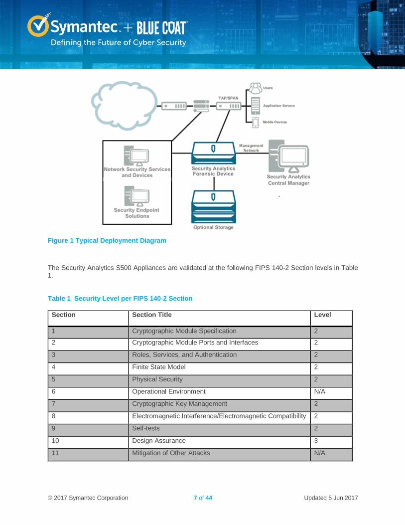
In a typical deployment, the Security Analytics Forensic Appliance receives mirrored traffic from a SPAN port or network tap. The traffic enters the appliance through one or more Ethernet ports, also known as capture interfaces. The Forensic Appliances can be integrated with leading security network and endpoint solutions for a full network-to-endpoint view of any malicious activity, delivering prompt and precise attack resolution. The Central Manager Platform is a dedicated appliance that sits on the network alongside the Forensic Appliances to provide an aggregated view of data across multiple Forensic Appliances, an interface for Forensic Appliance management, and centralized Forensic Appliance software upgrades. Please see Figure 1 below for a typical deployment diagram of the Security Analytics appliances.
© 2017 Symantec Corporation 7 of 44 Updated 5 Jun 2017
Figure 1 Typical Deployment Diagram
The Security Analytics S500 Appliances are validated at the following FIPS 140-2 Section levels in Table 1.
Table 1 Security Level per FIPS 140-2 Section
Section Section Title Level
1 Cryptographic Module Specification 2
2 Cryptographic Module Ports and Interfaces 2
3 Roles, Services, and Authentication 2
4 Finite State Model 2
5 Physical Security 2
6 Operational Environment N/A
7 Cryptographic Key Management 2
8 Electromagnetic Interference/Electromagnetic Compatibility 2
9 Self-tests 2
10 Design Assurance 3
11 Mitigation of Other Attacks N/A
© 2017 Symantec Corporation 8 of 44 Updated 5 Jun 2017
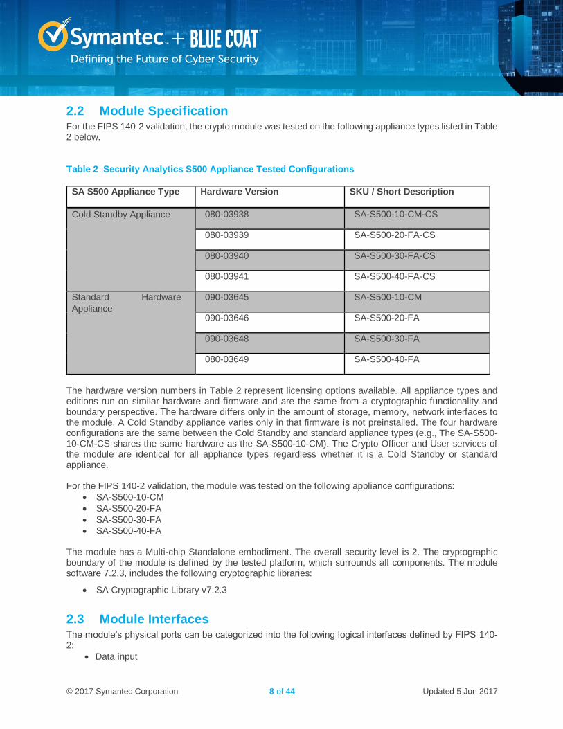
2.2 Module Specification For the FIPS 140-2 validation, the crypto module was tested on the following appliance types listed in Table 2 below.
Table 2 Security Analytics S500 Appliance Tested Configurations
SA S500 Appliance Type Hardware Version SKU / Short Description
Cold Standby Appliance 080-03938 SA-S500-10-CM-CS
080-03939 SA-S500-20-FA-CS
080-03940 SA-S500-30-FA-CS
080-03941 SA-S500-40-FA-CS
Standard Hardware
Appliance
090-03645 SA-S500-10-CM
090-03646 SA-S500-20-FA
090-03648 SA-S500-30-FA
080-03649 SA-S500-40-FA
The hardware version numbers in Table 2 represent licensing options available. All appliance types and editions run on similar hardware and firmware and are the same from a cryptographic functionality and boundary perspective. The hardware differs only in the amount of storage, memory, network interfaces to the module. A Cold Standby appliance varies only in that firmware is not preinstalled. The four hardware configurations are the same between the Cold Standby and standard appliance types (e.g., The SA-S500-10-CM-CS shares the same hardware as the SA-S500-10-CM). The Crypto Officer and User services of the module are identical for all appliance types regardless whether it is a Cold Standby or standard appliance. For the FIPS 140-2 validation, the module was tested on the following appliance configurations:
SA-S500-10-CM
SA-S500-20-FA
SA-S500-30-FA
SA-S500-40-FA The module has a Multi-chip Standalone embodiment. The overall security level is 2. The cryptographic boundary of the module is defined by the tested platform, which surrounds all components. The module software 7.2.3, includes the following cryptographic libraries:
SA Cryptographic Library v7.2.3
2.3 Module Interfaces The module’s physical ports can be categorized into the following logical interfaces defined by FIPS 140-2:
Data input
© 2017 Symantec Corporation 9 of 44 Updated 5 Jun 2017
Data output
Control input
Status output
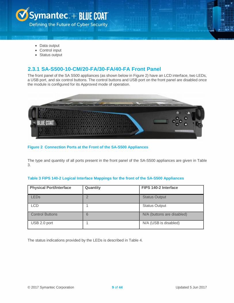
2.3.1 SA-S500-10-CM/20-FA/30-FA/40-FA Front Panel The front panel of the SA S500 appliances (as shown below in Figure 2) have an LCD interface, two LEDs, a USB port, and six control buttons. The control buttons and USB port on the front panel are disabled once the module is configured for its Approved mode of operation.
Figure 2 Connection Ports at the Front of the SA-S500 Appliances
The type and quantity of all ports present in the front panel of the SA-S500 appliances are given in Table 3.
Table 3 FIPS 140-2 Logical Interface Mappings for the front of the SA-S500 Appliances
Physical Port/Interface Quantity FIPS 140-2 Interface
LEDs 2 Status Output
LCD 1 Status Output
Control Buttons 6 N/A (buttons are disabled)
USB 2.0 port 1 N/A (USB is disabled)
The status indications provided by the LEDs is described in Table 4.
© 2017 Symantec Corporation 10 of 44 Updated 5 Jun 2017
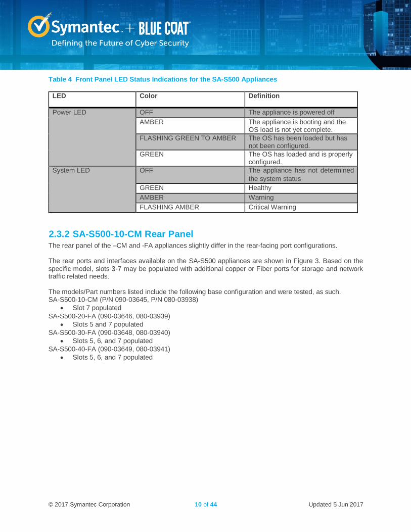
Table 4 Front Panel LED Status Indications for the SA-S500 Appliances
LED Color Definition
Power LED OFF The appliance is powered off
AMBER The appliance is booting and the OS load is not yet complete.
FLASHING GREEN TO AMBER The OS has been loaded but has not been configured.
GREEN The OS has loaded and is properly configured.
System LED OFF The appliance has not determined
the system status
GREEN Healthy
AMBER Warning
FLASHING AMBER Critical Warning
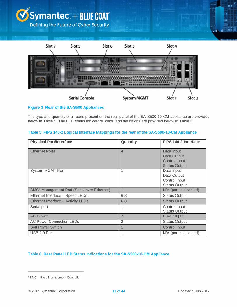
2.3.2 SA-S500-10-CM Rear Panel The rear panel of the –CM and -FA appliances slightly differ in the rear-facing port configurations. The rear ports and interfaces available on the SA-S500 appliances are shown in Figure 3. Based on the specific model, slots 3-7 may be populated with additional copper or Fiber ports for storage and network traffic related needs. The models/Part numbers listed include the following base configuration and were tested, as such. SA-S500-10-CM (P/N 090-03645, P/N 080-03938)
Slot 7 populated
SA-S500-20-FA (090-03646, 080-03939)
Slots 5 and 7 populated
SA-S500-30-FA (090-03648, 080-03940)
Slots 5, 6, and 7 populated
SA-S500-40-FA (090-03649, 080-03941)
Slots 5, 6, and 7 populated
© 2017 Symantec Corporation 11 of 44 Updated 5 Jun 2017
Figure 3 Rear of the SA-S500 Appliances
The type and quantity of all ports present on the rear panel of the SA-S500-10-CM appliance are provided below in Table 5. The LED status indicators, color, and definitions are provided below in Table 6.
Table 5 FIPS 140-2 Logical Interface Mappings for the rear of the SA-S500-10-CM Appliance
Physical Port/Interface Quantity FIPS 140-2 Interface
Ethernet Ports 4 Data Input
Data Output
Control Input
Status Output
System MGMT Port 1 Data Input
Data Output
Control Input
Status Output
BMC1 Management Port (Serial over Ethernet) 1 N/A (port is disabled)
Ethernet Interface – Speed LEDs 6-8 Status Output
Ethernet Interface – Activity LEDs 6-8 Status Output
Serial port 1 Control Input Status Output
AC Power 2 Power Input
AC Power Connection LEDs 2 Status Output
Soft Power Switch 1 Control Input
USB 2.0 Port 1 N/A (port is disabled)
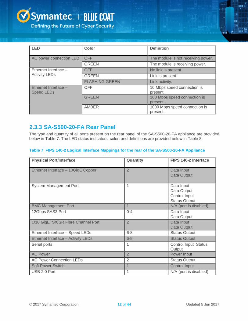
Table 6 Rear Panel LED Status Indications for the SA-S500-10-CM Appliance
1 BMC – Base Management Controller
© 2017 Symantec Corporation 12 of 44 Updated 5 Jun 2017
LED Color Definition
AC power connection LED OFF The module is not receiving power.
GREEN The module is receiving power.
Ethernet Interface – Activity LEDs
OFF No link is present.
GREEN Link is present
FLASHING GREEN Link activity.
Ethernet Interface – Speed LEDs
OFF 10 Mbps speed connection is present.
GREEN 100 Mbps speed connection is present.
AMBER 1000 Mbps speed connection is present.
2.3.3 SA-S500-20-FA Rear Panel The type and quantity of all ports present on the rear panel of the SA-S500-20-FA appliance are provided below in Table 7. The LED status indicators, color, and definitions are provided below in Table 8.
Table 7 FIPS 140-2 Logical Interface Mappings for the rear of the SA-S500-20-FA Appliance
Physical Port/Interface Quantity FIPS 140-2 Interface
Ethernet Interface – 10GigE Copper 2 Data Input
Data Output
System Management Port 1 Data Input
Data Output
Control Input
Status Output
BMC Management Port 1 N/A (port is disabled)
12Gbps SAS3 Port 0-4 Data Input
Data Output
1/10 GigE SX/SR Fibre Channel Port 2 Data Input
Data Output
Ethernet Interface – Speed LEDs 6-8 Status Output
Ethernet Interface – Activity LEDs 6-8 Status Output
Serial ports 1 Control Input Status Output
AC Power 2 Power Input
AC Power Connection LEDs 2 Status Output
Soft Power Switch 1 Control Input
USB 2.0 Port 1 N/A (port is disabled)
© 2017 Symantec Corporation 13 of 44 Updated 5 Jun 2017
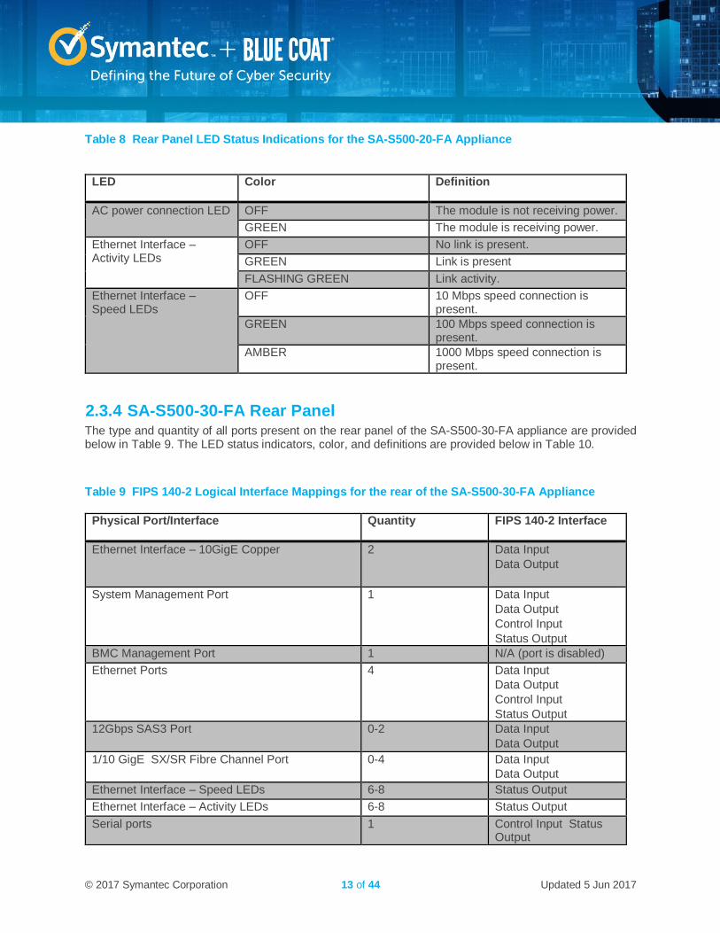
Table 8 Rear Panel LED Status Indications for the SA-S500-20-FA Appliance
LED Color Definition
AC power connection LED OFF The module is not receiving power.
GREEN The module is receiving power.
Ethernet Interface – Activity LEDs
OFF No link is present.
GREEN Link is present
FLASHING GREEN Link activity.
Ethernet Interface – Speed LEDs
OFF 10 Mbps speed connection is present.
GREEN 100 Mbps speed connection is present.
AMBER 1000 Mbps speed connection is present.
2.3.4 SA-S500-30-FA Rear Panel The type and quantity of all ports present on the rear panel of the SA-S500-30-FA appliance are provided below in Table 9. The LED status indicators, color, and definitions are provided below in Table 10.
Table 9 FIPS 140-2 Logical Interface Mappings for the rear of the SA-S500-30-FA Appliance
Physical Port/Interface Quantity FIPS 140-2 Interface
Ethernet Interface – 10GigE Copper 2 Data Input
Data Output
System Management Port 1 Data Input
Data Output
Control Input
Status Output
BMC Management Port 1 N/A (port is disabled)
Ethernet Ports 4 Data Input
Data Output
Control Input
Status Output
12Gbps SAS3 Port 0-2 Data Input
Data Output
1/10 GigE SX/SR Fibre Channel Port 0-4 Data Input
Data Output
Ethernet Interface – Speed LEDs 6-8 Status Output
Ethernet Interface – Activity LEDs 6-8 Status Output
Serial ports 1 Control Input Status Output
© 2017 Symantec Corporation 14 of 44 Updated 5 Jun 2017
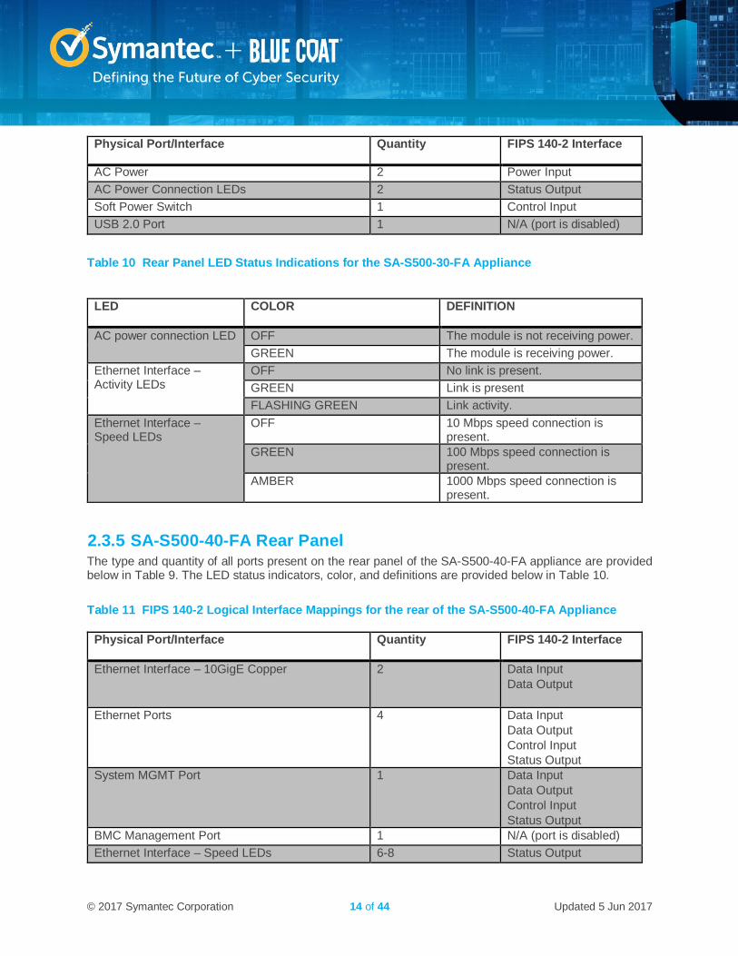
Physical Port/Interface Quantity FIPS 140-2 Interface
AC Power 2 Power Input
AC Power Connection LEDs 2 Status Output
Soft Power Switch 1 Control Input
USB 2.0 Port 1 N/A (port is disabled)
Table 10 Rear Panel LED Status Indications for the SA-S500-30-FA Appliance
LED COLOR DEFINITION
AC power connection LED OFF The module is not receiving power.
GREEN The module is receiving power.
Ethernet Interface – Activity LEDs
OFF No link is present.
GREEN Link is present
FLASHING GREEN Link activity.
Ethernet Interface – Speed LEDs
OFF 10 Mbps speed connection is present.
GREEN 100 Mbps speed connection is present.
AMBER 1000 Mbps speed connection is present.
2.3.5 SA-S500-40-FA Rear Panel The type and quantity of all ports present on the rear panel of the SA-S500-40-FA appliance are provided below in Table 9. The LED status indicators, color, and definitions are provided below in Table 10.
Table 11 FIPS 140-2 Logical Interface Mappings for the rear of the SA-S500-40-FA Appliance
Physical Port/Interface Quantity FIPS 140-2 Interface
Ethernet Interface – 10GigE Copper 2 Data Input
Data Output
Ethernet Ports 4 Data Input
Data Output
Control Input
Status Output
System MGMT Port 1 Data Input
Data Output
Control Input
Status Output
BMC Management Port 1 N/A (port is disabled)
Ethernet Interface – Speed LEDs 6-8 Status Output
© 2017 Symantec Corporation 15 of 44 Updated 5 Jun 2017
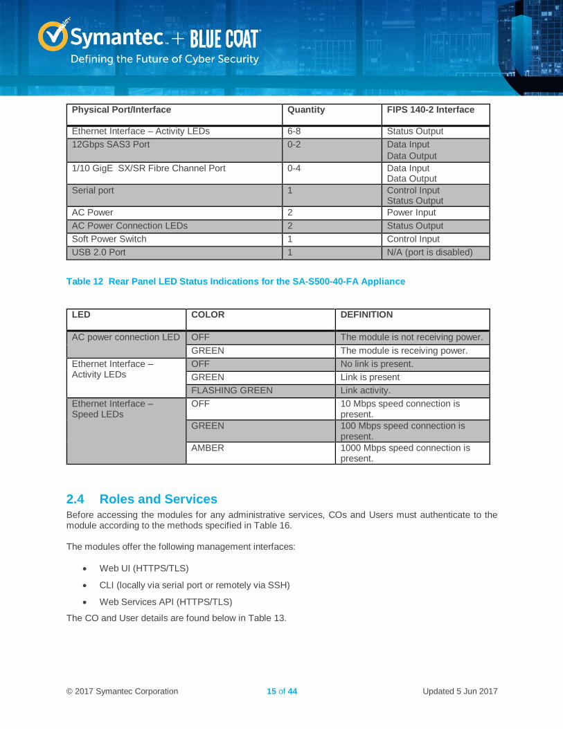
Physical Port/Interface Quantity FIPS 140-2 Interface
Ethernet Interface – Activity LEDs 6-8 Status Output
12Gbps SAS3 Port 0-2 Data Input
Data Output
1/10 GigE SX/SR Fibre Channel Port 0-4 Data Input Data Output
Serial port 1 Control Input Status Output
AC Power 2 Power Input
AC Power Connection LEDs 2 Status Output
Soft Power Switch 1 Control Input
USB 2.0 Port 1 N/A (port is disabled)
Table 12 Rear Panel LED Status Indications for the SA-S500-40-FA Appliance
LED COLOR DEFINITION
AC power connection LED OFF The module is not receiving power.
GREEN The module is receiving power.
Ethernet Interface – Activity LEDs
OFF No link is present.
GREEN Link is present
FLASHING GREEN Link activity.
Ethernet Interface – Speed LEDs
OFF 10 Mbps speed connection is present.
GREEN 100 Mbps speed connection is present.
AMBER 1000 Mbps speed connection is present.
2.4 Roles and Services Before accessing the modules for any administrative services, COs and Users must authenticate to the module according to the methods specified in Table 16. The modules offer the following management interfaces:
Web UI (HTTPS/TLS)
CLI (locally via serial port or remotely via SSH)
Web Services API (HTTPS/TLS)
The CO and User details are found below in Table 13.
© 2017 Symantec Corporation 16 of 44 Updated 5 Jun 2017
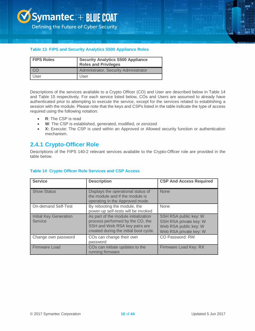
Table 13 FIPS and Security Analytics S500 Appliance Roles
FIPS Roles Security Analytics S500 Appliance Roles and Privileges
CO Administrator, Security Administrator
User User
Descriptions of the services available to a Crypto Officer (CO) and User are described below in Table 14 and Table 15 respectively. For each service listed below, COs and Users are assumed to already have authenticated prior to attempting to execute the service, except for the services related to establishing a session with the module. Please note that the keys and CSPs listed in the table indicate the type of access required using the following notation:
R: The CSP is read
W: The CSP is established, generated, modified, or zeroized
X: Execute: The CSP is used within an Approved or Allowed security function or authentication mechanism.
2.4.1 Crypto-Officer Role Descriptions of the FIPS 140-2 relevant services available to the Crypto-Officer role are provided in the table below.
Table 14 Crypto Officer Role Services and CSP Access
Service Description CSP And Access Required
Show Status Displays the operational status of the module and if the module is operating in the Approved mode.
None
On-demand Self-Test By rebooting the module, the power-up self-tests will be invoked
None
Initial Key Generation Service
As part of the module initialization process performed by the CO, the SSH and Web RSA key pairs are created during the initial boot cycle.
SSH RSA public key: W
SSH RSA private key: W Web RSA public key: W
Web RSA private key: W
Change own password COs can change their own password
CO Password: RW
Firmware Load COs can initiate updates to the running firmware
Firmware Load Key: RX
© 2017 Symantec Corporation 17 of 44 Updated 5 Jun 2017
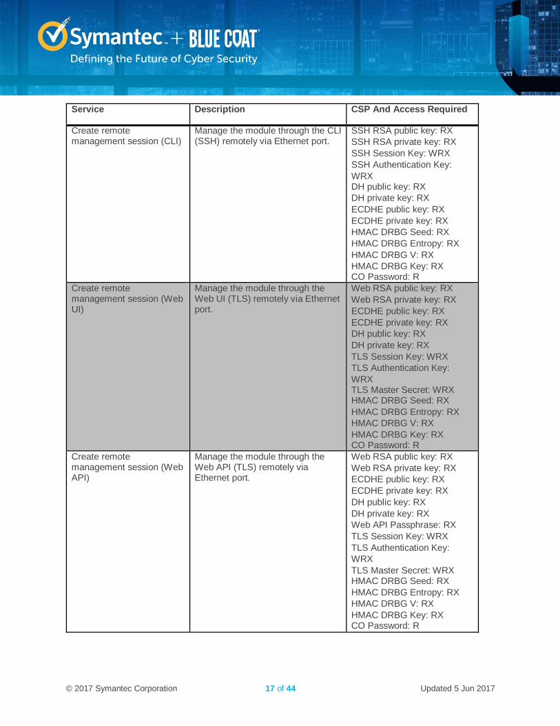
Service Description CSP And Access Required
Create remote management session (CLI)
Manage the module through the CLI (SSH) remotely via Ethernet port.
SSH RSA public key: RX
SSH RSA private key: RX
SSH Session Key: WRX
SSH Authentication Key:
WRX DH public key: RX
DH private key: RX
ECDHE public key: RX
ECDHE private key: RX
HMAC DRBG Seed: RX
HMAC DRBG Entropy: RX
HMAC DRBG V: RX
HMAC DRBG Key: RX CO Password: R
Create remote management session (Web UI)
Manage the module through the Web UI (TLS) remotely via Ethernet port.
Web RSA public key: RX
Web RSA private key: RX
ECDHE public key: RX
ECDHE private key: RX
DH public key: RX
DH private key: RX
TLS Session Key: WRX
TLS Authentication Key:
WRX TLS Master Secret: WRX HMAC DRBG Seed: RX
HMAC DRBG Entropy: RX
HMAC DRBG V: RX
HMAC DRBG Key: RX CO Password: R
Create remote management session (Web API)
Manage the module through the Web API (TLS) remotely via Ethernet port.
Web RSA public key: RX
Web RSA private key: RX
ECDHE public key: RX
ECDHE private key: RX
DH public key: RX
DH private key: RX
Web API Passphrase: RX
TLS Session Key: WRX
TLS Authentication Key:
WRX
TLS Master Secret: WRX HMAC DRBG Seed: RX
HMAC DRBG Entropy: RX
HMAC DRBG V: RX
HMAC DRBG Key: RX CO Password: R
© 2017 Symantec Corporation 18 of 44 Updated 5 Jun 2017
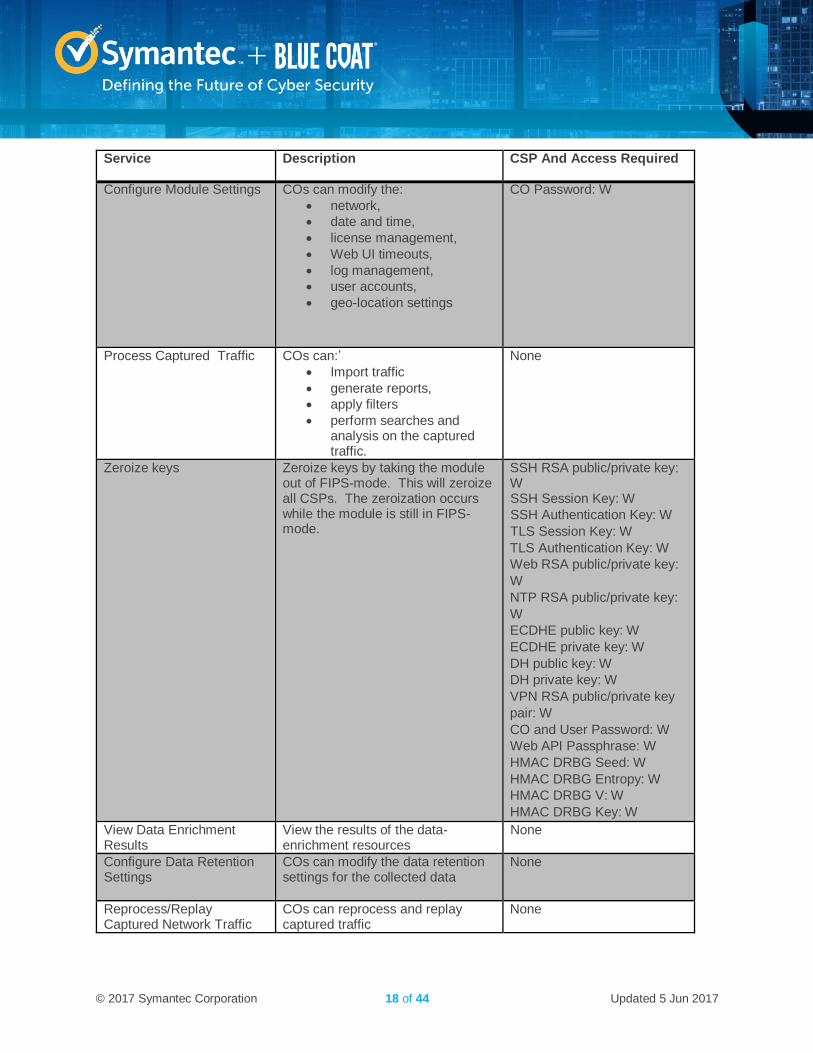
Service Description CSP And Access Required
Configure Module Settings COs can modify the:
network,
date and time,
license management,
Web UI timeouts,
log management,
user accounts,
geo-location settings
CO Password: W
Process Captured Traffic COs can:’
Import traffic
generate reports,
apply filters
perform searches and analysis on the captured traffic.
None
Zeroize keys Zeroize keys by taking the module out of FIPS-mode. This will zeroize all CSPs. The zeroization occurs while the module is still in FIPS-mode.
SSH RSA public/private key: W SSH Session Key: W
SSH Authentication Key: W
TLS Session Key: W
TLS Authentication Key: W
Web RSA public/private key:
W
NTP RSA public/private key:
W
ECDHE public key: W
ECDHE private key: W
DH public key: W
DH private key: W
VPN RSA public/private key
pair: W
CO and User Password: W
Web API Passphrase: W
HMAC DRBG Seed: W
HMAC DRBG Entropy: W
HMAC DRBG V: W
HMAC DRBG Key: W
View Data Enrichment Results
View the results of the data-enrichment resources
None
Configure Data Retention Settings
COs can modify the data retention settings for the collected data
None
Reprocess/Replay Captured Network Traffic
COs can reprocess and replay captured traffic
None
© 2017 Symantec Corporation 19 of 44 Updated 5 Jun 2017
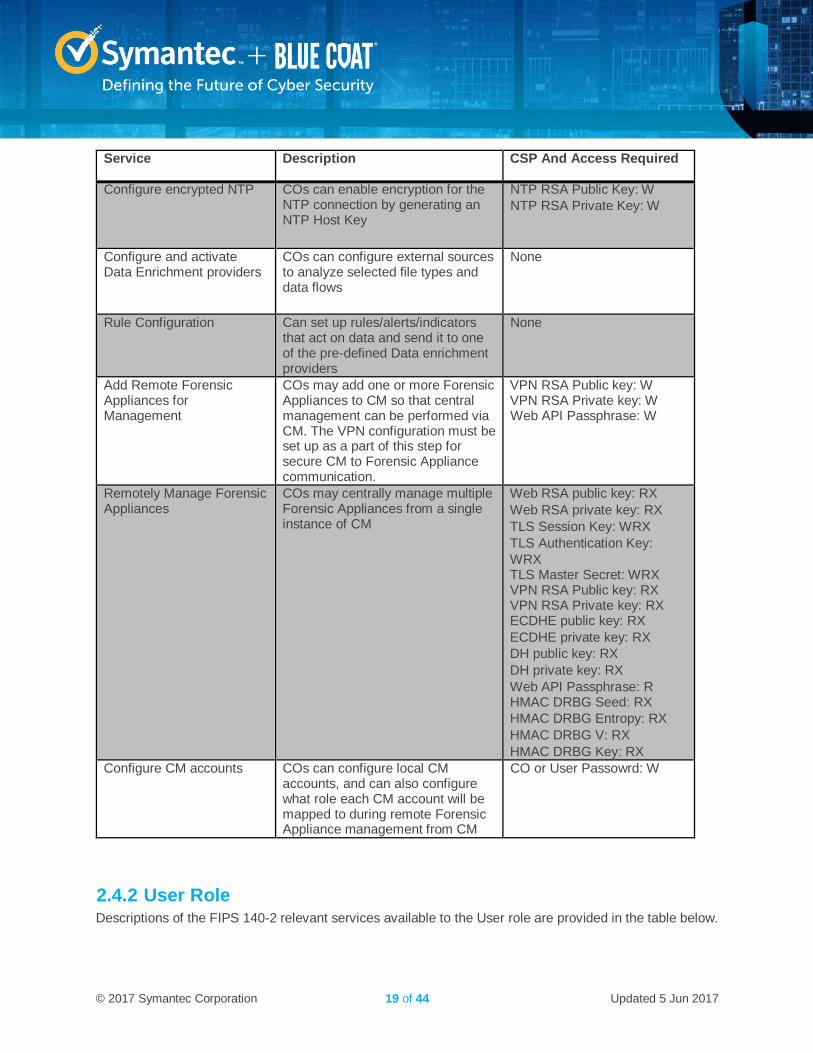
Service Description CSP And Access Required
Configure encrypted NTP COs can enable encryption for the NTP connection by generating an NTP Host Key
NTP RSA Public Key: W
NTP RSA Private Key: W
Configure and activate Data Enrichment providers
COs can configure external sources to analyze selected file types and data flows
None
Rule Configuration Can set up rules/alerts/indicators that act on data and send it to one of the pre-defined Data enrichment providers
None
Add Remote Forensic Appliances for Management
COs may add one or more Forensic Appliances to CM so that central management can be performed via CM. The VPN configuration must be set up as a part of this step for secure CM to Forensic Appliance communication.
VPN RSA Public key: W VPN RSA Private key: W Web API Passphrase: W
Remotely Manage Forensic Appliances
COs may centrally manage multiple Forensic Appliances from a single instance of CM
Web RSA public key: RX
Web RSA private key: RX
TLS Session Key: WRX
TLS Authentication Key:
WRX TLS Master Secret: WRX VPN RSA Public key: RX VPN RSA Private key: RX ECDHE public key: RX
ECDHE private key: RX
DH public key: RX
DH private key: RX
Web API Passphrase: R HMAC DRBG Seed: RX
HMAC DRBG Entropy: RX
HMAC DRBG V: RX
HMAC DRBG Key: RX
Configure CM accounts COs can configure local CM accounts, and can also configure what role each CM account will be mapped to during remote Forensic Appliance management from CM
CO or User Passowrd: W
2.4.2 User Role Descriptions of the FIPS 140-2 relevant services available to the User role are provided in the table below.
© 2017 Symantec Corporation 20 of 44 Updated 5 Jun 2017
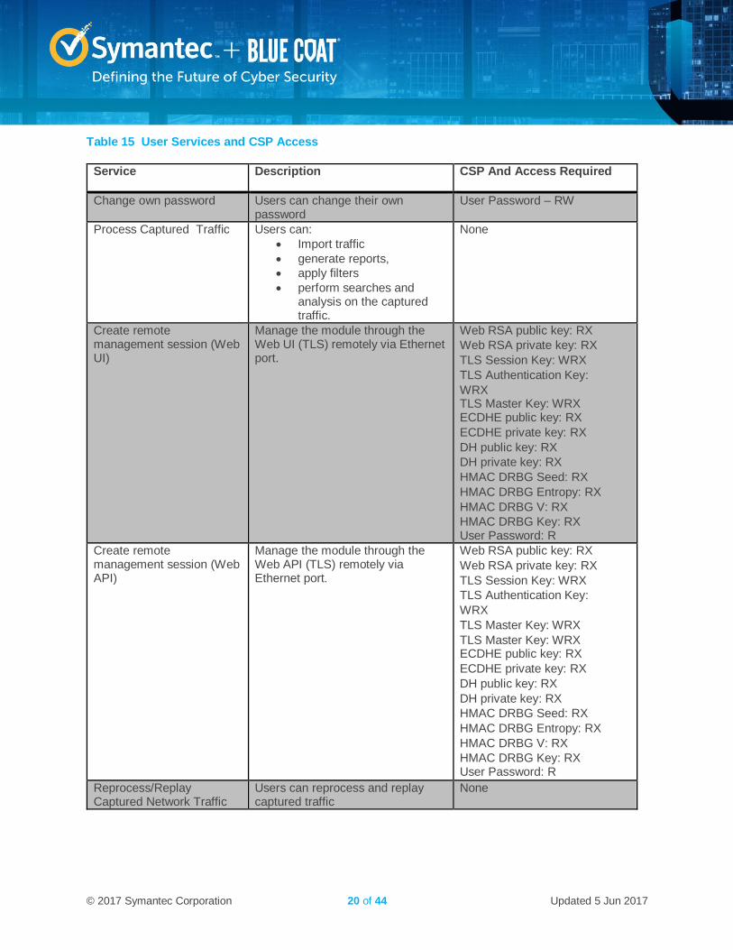
Table 15 User Services and CSP Access
Service Description CSP And Access Required
Change own password Users can change their own password
User Password – RW
Process Captured Traffic Users can:
Import traffic
generate reports,
apply filters
perform searches and analysis on the captured traffic.
None
Create remote management session (Web UI)
Manage the module through the Web UI (TLS) remotely via Ethernet port.
Web RSA public key: RX
Web RSA private key: RX
TLS Session Key: WRX
TLS Authentication Key:
WRX TLS Master Key: WRX ECDHE public key: RX
ECDHE private key: RX
DH public key: RX
DH private key: RX
HMAC DRBG Seed: RX
HMAC DRBG Entropy: RX
HMAC DRBG V: RX
HMAC DRBG Key: RX User Password: R
Create remote management session (Web API)
Manage the module through the Web API (TLS) remotely via Ethernet port.
Web RSA public key: RX
Web RSA private key: RX
TLS Session Key: WRX
TLS Authentication Key:
WRX
TLS Master Key: WRX
TLS Master Key: WRX ECDHE public key: RX
ECDHE private key: RX
DH public key: RX
DH private key: RX
HMAC DRBG Seed: RX
HMAC DRBG Entropy: RX
HMAC DRBG V: RX
HMAC DRBG Key: RX User Password: R
Reprocess/Replay Captured Network Traffic
Users can reprocess and replay captured traffic
None
© 2017 Symantec Corporation 21 of 44 Updated 5 Jun 2017
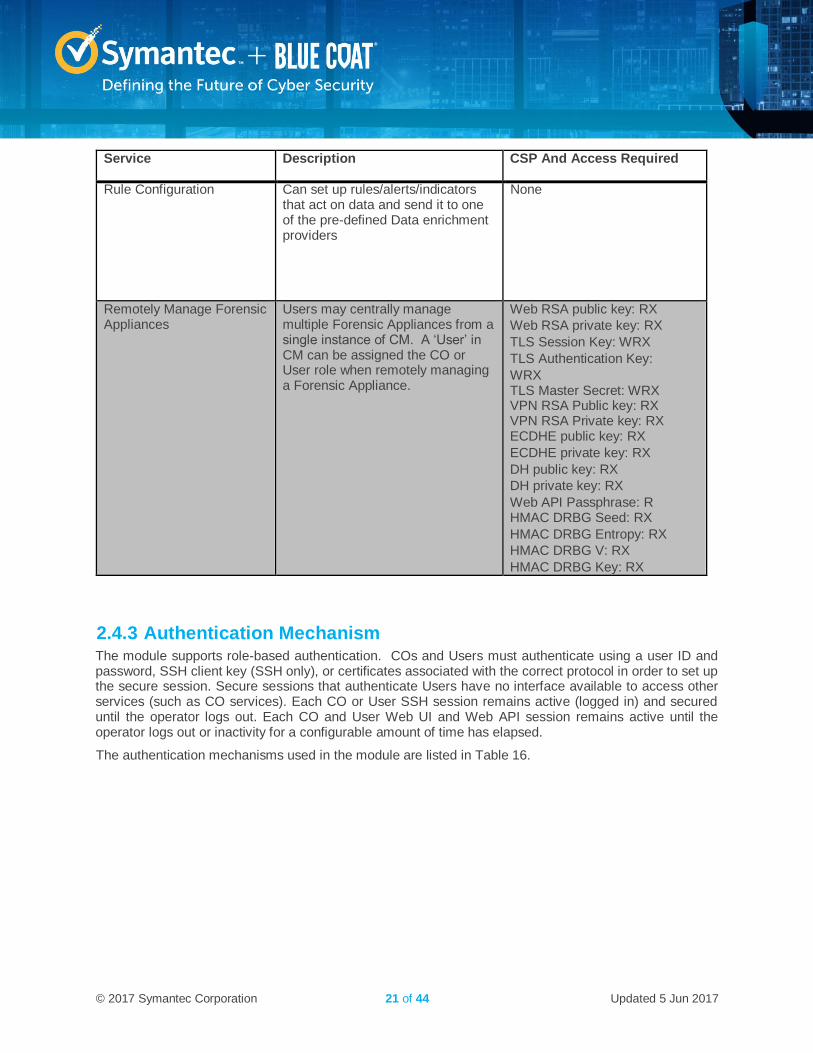
Service Description CSP And Access Required
Rule Configuration Can set up rules/alerts/indicators that act on data and send it to one of the pre-defined Data enrichment providers
None
Remotely Manage Forensic Appliances
Users may centrally manage multiple Forensic Appliances from a single instance of CM. A ‘User’ in CM can be assigned the CO or User role when remotely managing a Forensic Appliance.
Web RSA public key: RX
Web RSA private key: RX
TLS Session Key: WRX
TLS Authentication Key:
WRX TLS Master Secret: WRX VPN RSA Public key: RX VPN RSA Private key: RX ECDHE public key: RX
ECDHE private key: RX
DH public key: RX
DH private key: RX
Web API Passphrase: R HMAC DRBG Seed: RX
HMAC DRBG Entropy: RX
HMAC DRBG V: RX
HMAC DRBG Key: RX
2.4.3 Authentication Mechanism The module supports role-based authentication. COs and Users must authenticate using a user ID and password, SSH client key (SSH only), or certificates associated with the correct protocol in order to set up the secure session. Secure sessions that authenticate Users have no interface available to access other services (such as CO services). Each CO or User SSH session remains active (logged in) and secured until the operator logs out. Each CO and User Web UI and Web API session remains active until the operator logs out or inactivity for a configurable amount of time has elapsed.
The authentication mechanisms used in the module are listed in Table 16.
© 2017 Symantec Corporation 22 of 44 Updated 5 Jun 2017
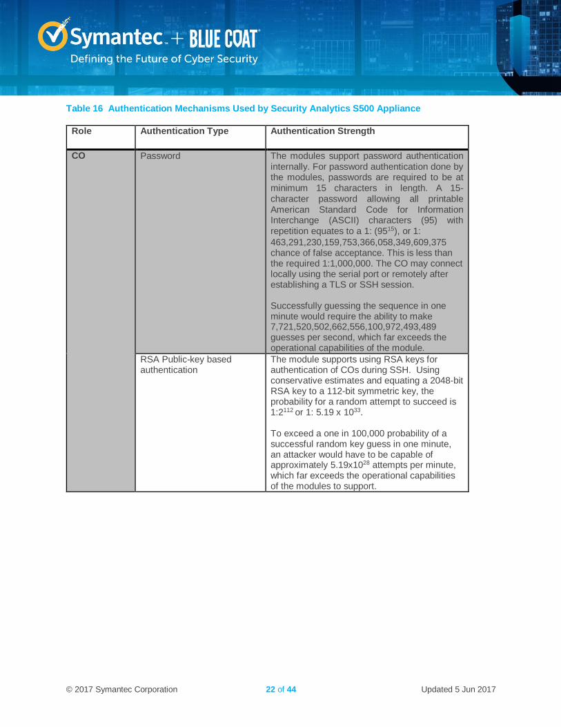
Table 16 Authentication Mechanisms Used by Security Analytics S500 Appliance
Role Authentication Type Authentication Strength
CO Password The modules support password authentication internally. For password authentication done by the modules, passwords are required to be at minimum 15 characters in length. A 15-character password allowing all printable American Standard Code for Information Interchange (ASCII) characters (95) with repetition equates to a 1: (9515), or 1:
463,291,230,159,753,366,058,349,609,375 chance of false acceptance. This is less than the required 1:1,000,000. The CO may connect locally using the serial port or remotely after establishing a TLS or SSH session. Successfully guessing the sequence in one minute would require the ability to make 7,721,520,502,662,556,100,972,493,489 guesses per second, which far exceeds the operational capabilities of the module.
RSA Public-key based authentication
The module supports using RSA keys for authentication of COs during SSH. Using conservative estimates and equating a 2048-bit RSA key to a 112-bit symmetric key, the probability for a random attempt to succeed is 1:2112 or 1: 5.19 x 1033. To exceed a one in 100,000 probability of a successful random key guess in one minute, an attacker would have to be capable of approximately 5.19x1028 attempts per minute, which far exceeds the operational capabilities of the modules to support.
© 2017 Symantec Corporation 23 of 44 Updated 5 Jun 2017
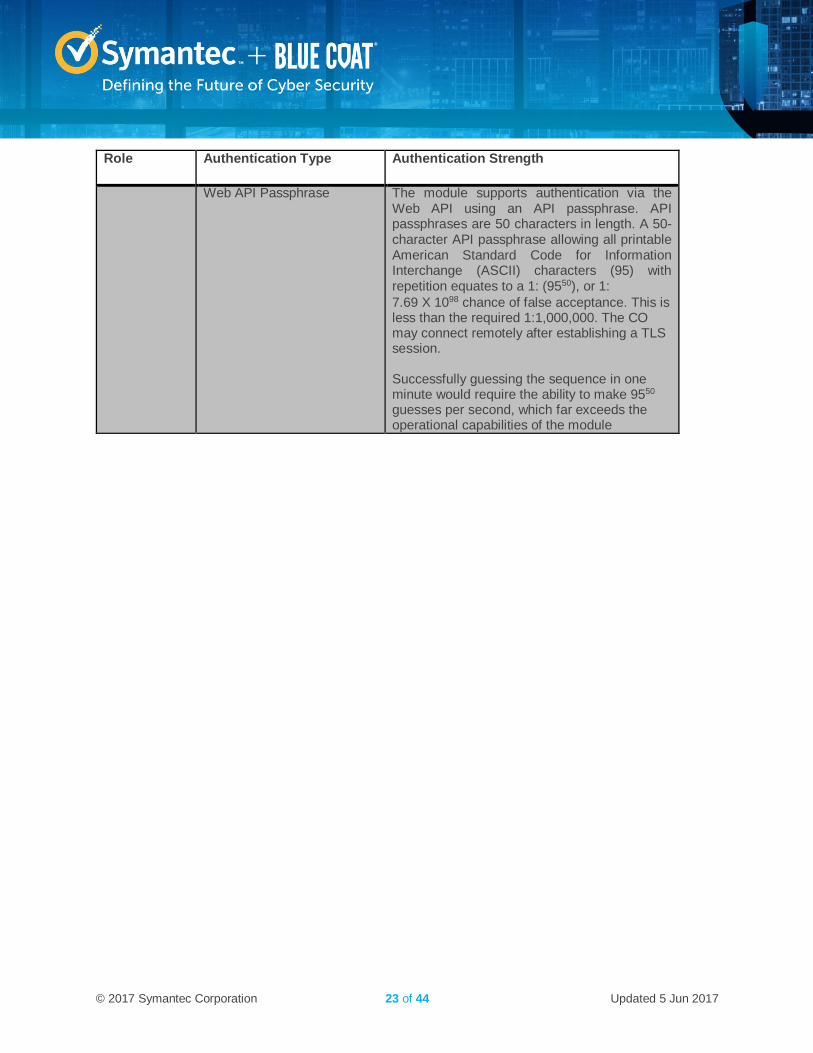
Role Authentication Type Authentication Strength
Web API Passphrase The module supports authentication via the Web API using an API passphrase. API passphrases are 50 characters in length. A 50-character API passphrase allowing all printable American Standard Code for Information Interchange (ASCII) characters (95) with repetition equates to a 1: (9550), or 1:
7.69 X 1098 chance of false acceptance. This is less than the required 1:1,000,000. The CO may connect remotely after establishing a TLS session. Successfully guessing the sequence in one minute would require the ability to make 9550 guesses per second, which far exceeds the operational capabilities of the module
© 2017 Symantec Corporation 24 of 44 Updated 5 Jun 2017
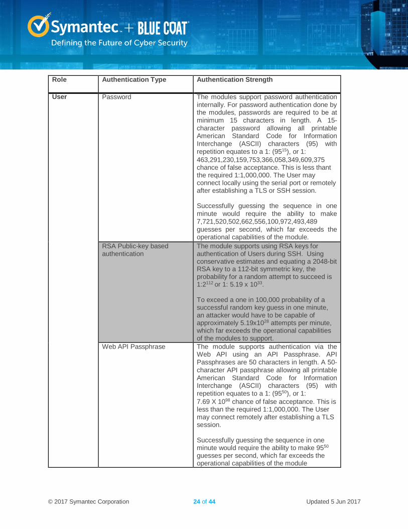
Role Authentication Type Authentication Strength
User Password The modules support password authentication internally. For password authentication done by the modules, passwords are required to be at minimum 15 characters in length. A 15-character password allowing all printable American Standard Code for Information Interchange (ASCII) characters (95) with repetition equates to a 1: (9515), or 1:
463,291,230,159,753,366,058,349,609,375 chance of false acceptance. This is less thant the required 1:1,000,000. The User may connect locally using the serial port or remotely after establishing a TLS or SSH session. Successfully guessing the sequence in one minute would require the ability to make 7,721,520,502,662,556,100,972,493,489 guesses per second, which far exceeds the operational capabilities of the module.
RSA Public-key based authentication
The module supports using RSA keys for authentication of Users during SSH. Using conservative estimates and equating a 2048-bit RSA key to a 112-bit symmetric key, the probability for a random attempt to succeed is 1:2112 or 1: 5.19 x 1033. To exceed a one in 100,000 probability of a successful random key guess in one minute, an attacker would have to be capable of approximately 5.19x1028 attempts per minute, which far exceeds the operational capabilities of the modules to support.
Web API Passphrase The module supports authentication via the Web API using an API Passphrase. API Passphrases are 50 characters in length. A 50-character API passphrase allowing all printable American Standard Code for Information Interchange (ASCII) characters (95) with repetition equates to a 1: (9550), or 1:
7.69 X 1098 chance of false acceptance. This is less than the required 1:1,000,000. The User may connect remotely after establishing a TLS session. Successfully guessing the sequence in one minute would require the ability to make 9550 guesses per second, which far exceeds the operational capabilities of the module
© 2017 Symantec Corporation 25 of 44 Updated 5 Jun 2017
2.5 Physical Security The Security Analytics S500 Appliance is a multi-chip standalone cryptographic module and is enclosed in a hard, opaque metal case that completely encloses all of its internal components. There are only a limited set of vent holes provided in the case, and these holes obscure the view of the internal components of the module. Tamper-evident labels are applied to the case to provide physical evidence of attempts to remove the case of the module. The Crypto-Officer is responsible for the placement of tamper-evident labels and baffles and guidance can be found in section 3.1.1. The labels and baffles are part of the FIPS Security Kit (Part Number: HW-KIT-FIPS-500).
All of the module’s components are production grade. The Security Analytics S500 Appliance (10-CM, 20-FA, 30-FA, and 40-FA-F) were tested and found conformant to the EMI/EMC requirements specified by 47 Code of Federal Regulations, Part 15, Subpart B, Unintentional Radiators, Digital Devices, Class A (i.e., for business use).
2.6 Non-Modifiable Operational Environment The operational environment of the modules does not provide a general-purpose operating system (OS) to the user. The SA-S500 Appliances run Red Hat Fedora-based kernel in a non-modifiable operational environment. The operating system is not modifiable by the operator, and only the modules’ signed image can be executed. All firmware upgrades are digitally-signed, and a conditional self-test (RSA signature verification) is performed during each upgrade.
NOTE: Only FIPS-validated firmware may be loaded to maintain the module’s validation.
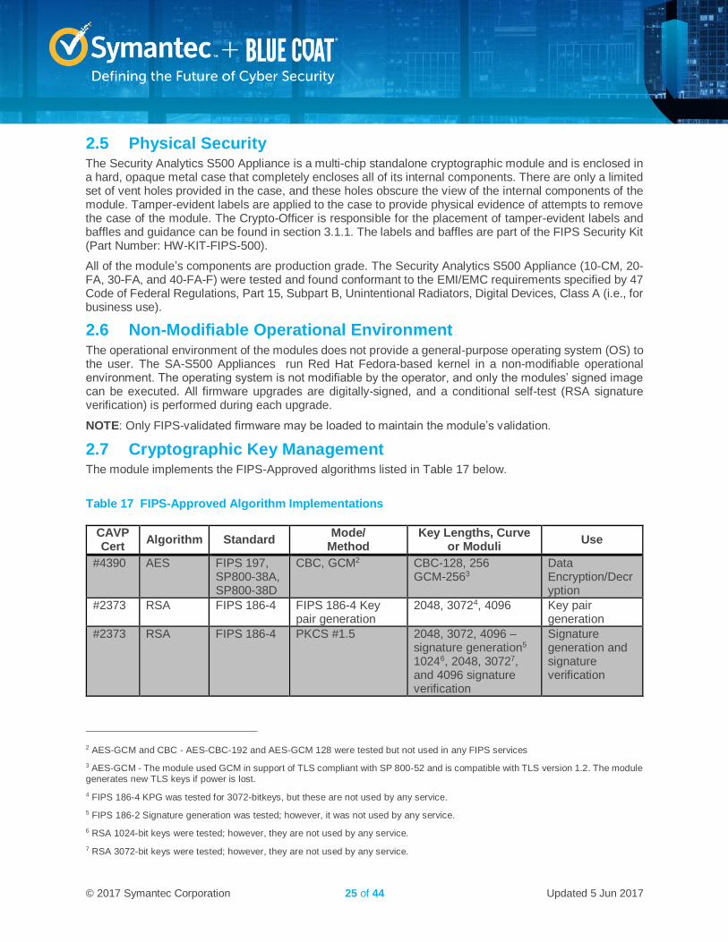
2.7 Cryptographic Key Management The module implements the FIPS-Approved algorithms listed in Table 17 below.
Table 17 FIPS-Approved Algorithm Implementations
CAVP Cert
Algorithm Standard Mode/
Method Key Lengths, Curve
or Moduli Use
#4390 AES FIPS 197, SP800-38A, SP800-38D
CBC, GCM2 CBC-128, 256 GCM-2563
Data Encryption/Decryption
#2373 RSA FIPS 186-4 FIPS 186-4 Key pair generation
2048, 30724, 4096 Key pair generation
#2373 RSA FIPS 186-4 PKCS #1.5 2048, 3072, 4096 – signature generation5 10246, 2048, 30727, and 4096 signature verification
Signature generation and signature verification
2 AES-GCM and CBC - AES-CBC-192 and AES-GCM 128 were tested but not used in any FIPS services
3 AES-GCM - The module used GCM in support of TLS compliant with SP 800-52 and is compatible with TLS version 1.2. The module generates new TLS keys if power is lost.
4 FIPS 186-4 KPG was tested for 3072-bitkeys, but these are not used by any service.
5 FIPS 186-2 Signature generation was tested; however, it was not used by any service.
6 RSA 1024-bit keys were tested; however, they are not used by any service.
7 RSA 3072-bit keys were tested; however, they are not used by any service.
© 2017 Symantec Corporation 26 of 44 Updated 5 Jun 2017
CAVP Cert
Algorithm Standard Mode/
Method Key Lengths, Curve
or Moduli Use
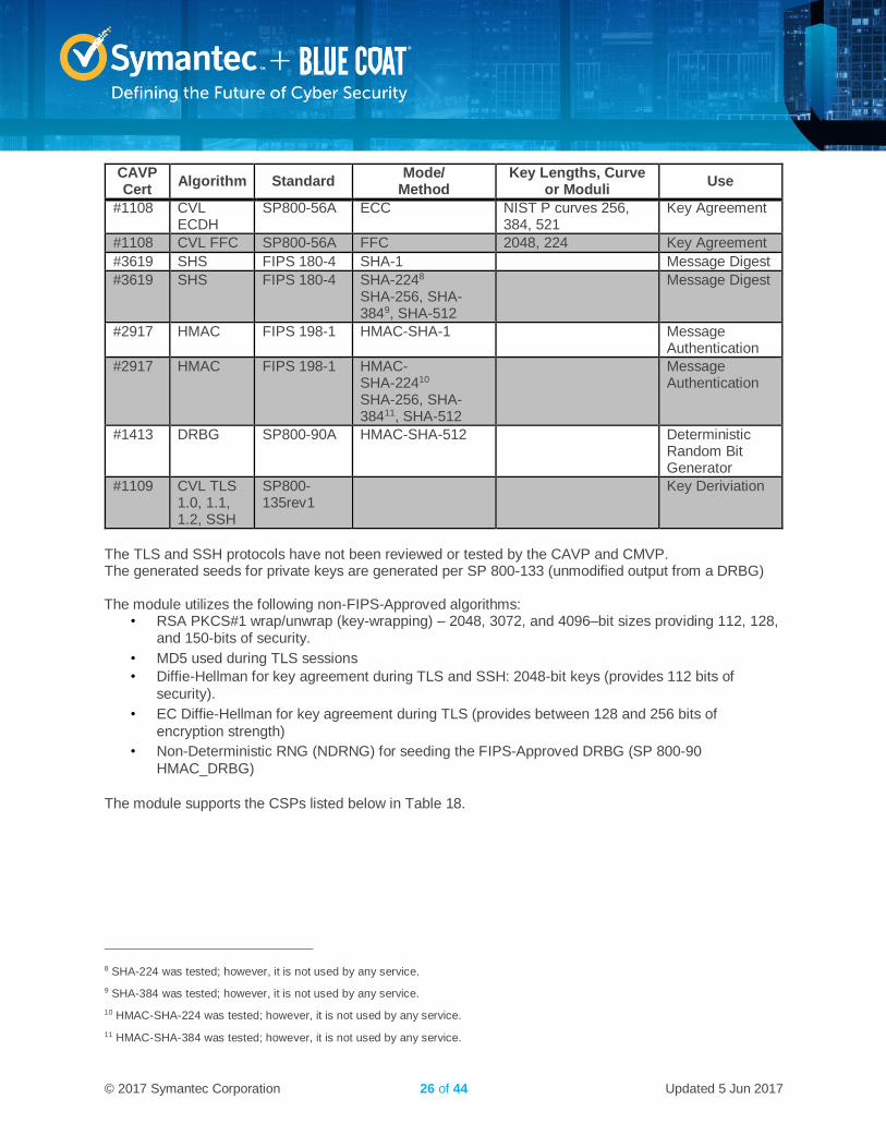
#1108 CVL ECDH
SP800-56A ECC NIST P curves 256, 384, 521
Key Agreement
#1108 CVL FFC SP800-56A FFC 2048, 224 Key Agreement
#3619 SHS FIPS 180-4 SHA-1 Message Digest
#3619 SHS FIPS 180-4 SHA-2248 SHA-256, SHA-3849, SHA-512
Message Digest
#2917 HMAC FIPS 198-1 HMAC-SHA-1 Message Authentication
#2917 HMAC FIPS 198-1 HMAC- SHA-22410 SHA-256, SHA-38411, SHA-512
Message Authentication
#1413 DRBG SP800-90A HMAC-SHA-512 Deterministic Random Bit Generator
#1109 CVL TLS 1.0, 1.1, 1.2, SSH
SP800-135rev1
Key Deriviation
The TLS and SSH protocols have not been reviewed or tested by the CAVP and CMVP. The generated seeds for private keys are generated per SP 800-133 (unmodified output from a DRBG) The module utilizes the following non-FIPS-Approved algorithms:
• RSA PKCS#1 wrap/unwrap (key-wrapping) – 2048, 3072, and 4096–bit sizes providing 112, 128, and 150-bits of security.
• MD5 used during TLS sessions
• Diffie-Hellman for key agreement during TLS and SSH: 2048-bit keys (provides 112 bits of
security).
• EC Diffie-Hellman for key agreement during TLS (provides between 128 and 256 bits of
encryption strength)
• Non-Deterministic RNG (NDRNG) for seeding the FIPS-Approved DRBG (SP 800-90
HMAC_DRBG)
The module supports the CSPs listed below in Table 18.
8 SHA-224 was tested; however, it is not used by any service.
9 SHA-384 was tested; however, it is not used by any service.
10 HMAC-SHA-224 was tested; however, it is not used by any service.
11 HMAC-SHA-384 was tested; however, it is not used by any service.
© 2017 Symantec Corporation 27 of 44 Updated 5 Jun 2017
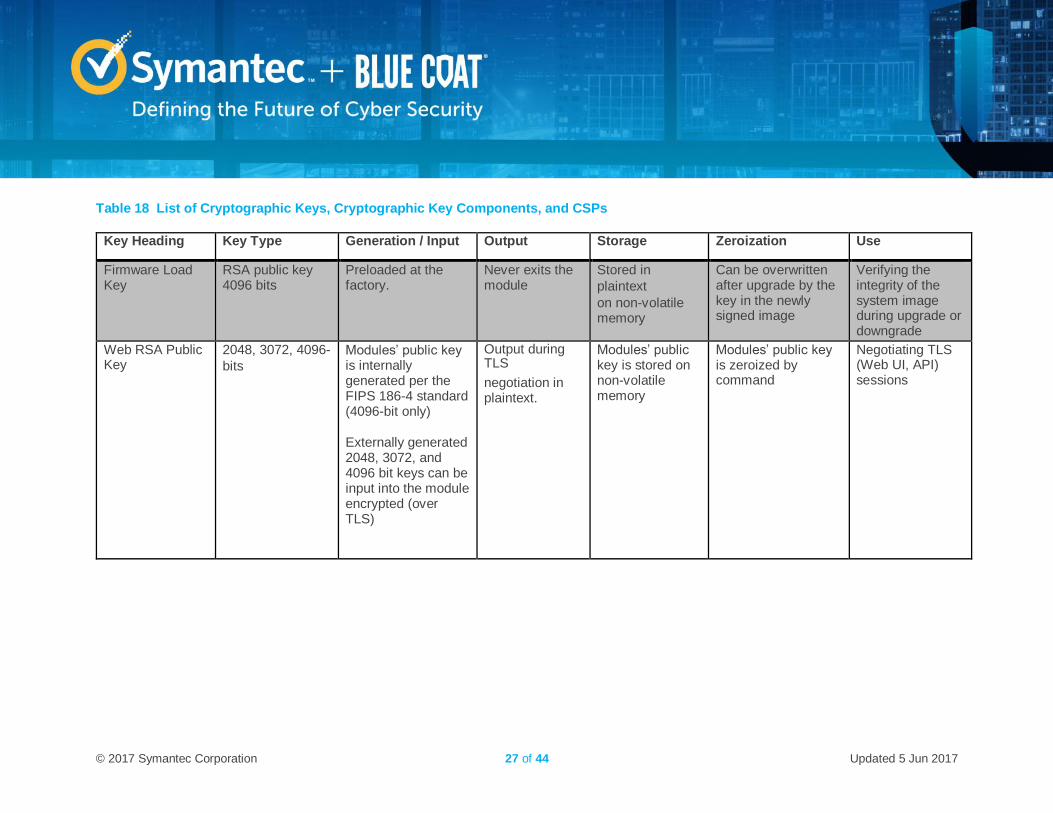
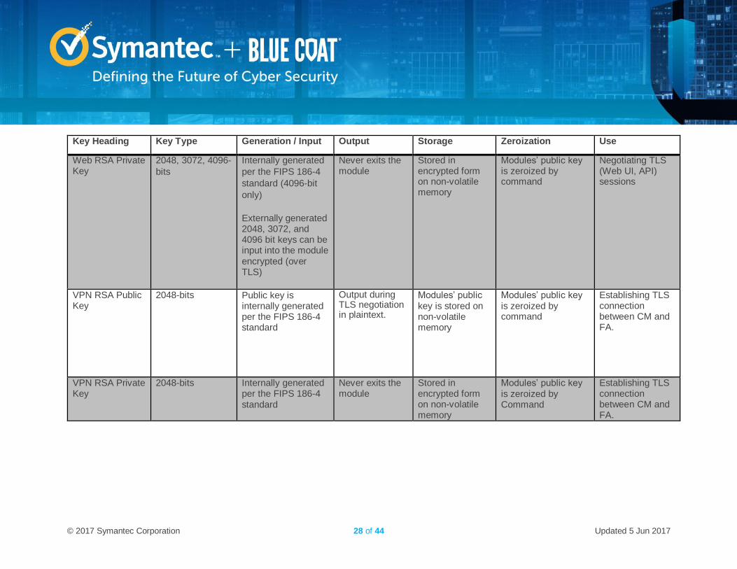
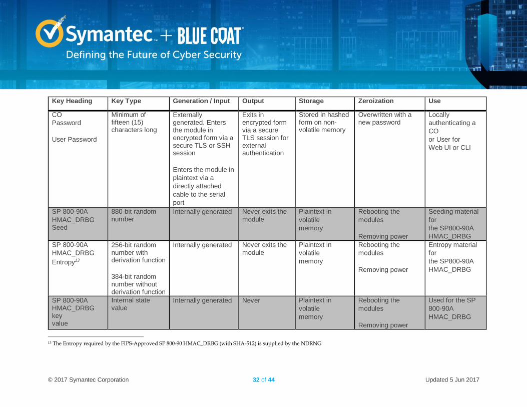
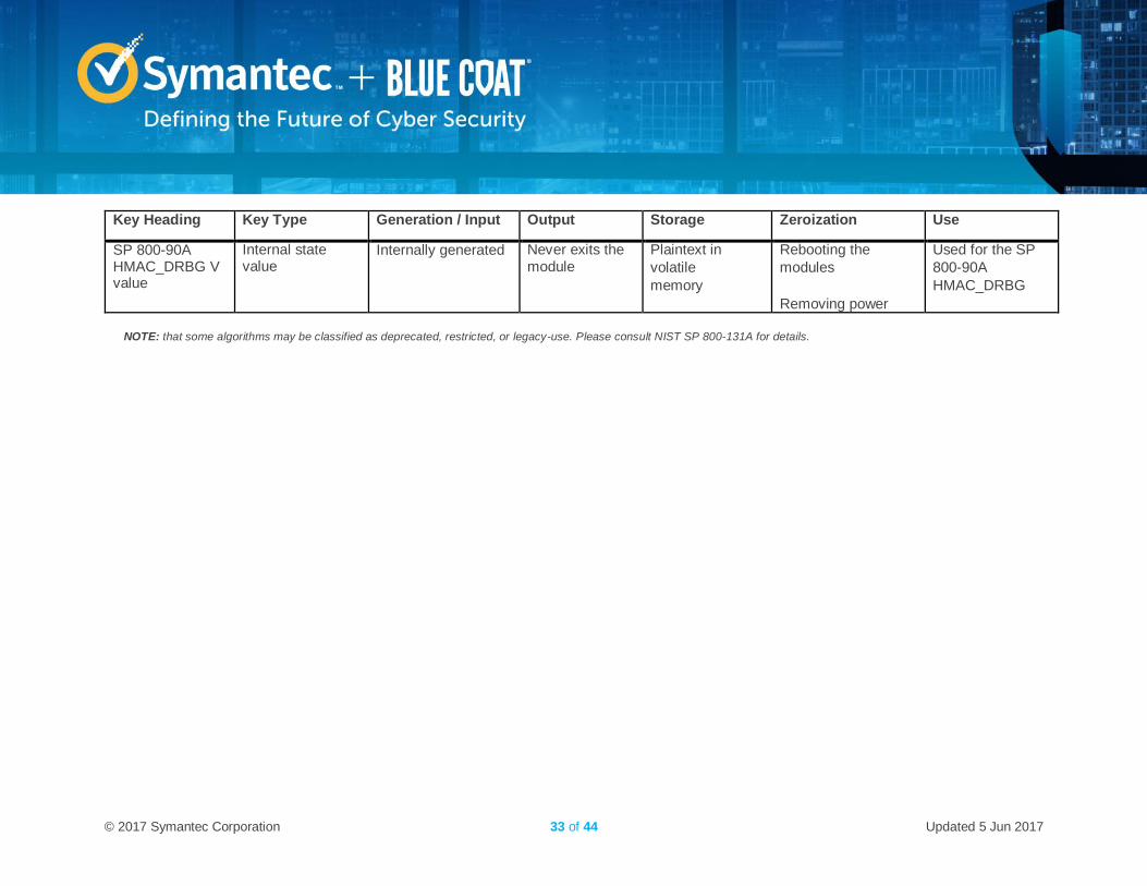
Table 18 List of Cryptographic Keys, Cryptographic Key Components, and CSPs
Key Heading Key Type Generation / Input Output Storage Zeroization Use
Firmware Load Key
RSA public key 4096 bits
Preloaded at the factory.
Never exits the module
Stored in
plaintext
on non-volatile memory
Can be overwritten after upgrade by the key in the newly signed image
Verifying the integrity of the system image during upgrade or downgrade
Web RSA Public Key
2048, 3072, 4096-
bits
Modules’ public key is internally generated per the FIPS 186-4 standard (4096-bit only) Externally generated 2048, 3072, and 4096 bit keys can be input into the module encrypted (over TLS)
Output during TLS
negotiation in plaintext.
Modules’ public key is stored on non-volatile memory
Modules’ public key is zeroized by command
Negotiating TLS (Web UI, API) sessions
© 2017 Symantec Corporation 28 of 44 Updated 5 Jun 2017
Key Heading Key Type Generation / Input Output Storage Zeroization Use
Web RSA Private Key
2048, 3072, 4096-
bits
Internally generated
per the FIPS 186-4
standard (4096-bit
only)
Externally generated 2048, 3072, and 4096 bit keys can be input into the module encrypted (over TLS)
Never exits the module
Stored in encrypted form on non-volatile memory
Modules’ public key is zeroized by command
Negotiating TLS (Web UI, API) sessions
VPN RSA Public Key
2048-bits Public key is internally generated per the FIPS 186-4 standard
Output during TLS negotiation in plaintext.
Modules’ public key is stored on non-volatile memory
Modules’ public key is zeroized by command
Establishing TLS connection between CM and FA.
VPN RSA Private Key
2048-bits Internally generated per the FIPS 186-4 standard
Never exits the module
Stored in encrypted form on non-volatile memory
Modules’ public key is zeroized by Command
Establishing TLS connection between CM and FA.
© 2017 Symantec Corporation 29 of 44 Updated 5 Jun 2017
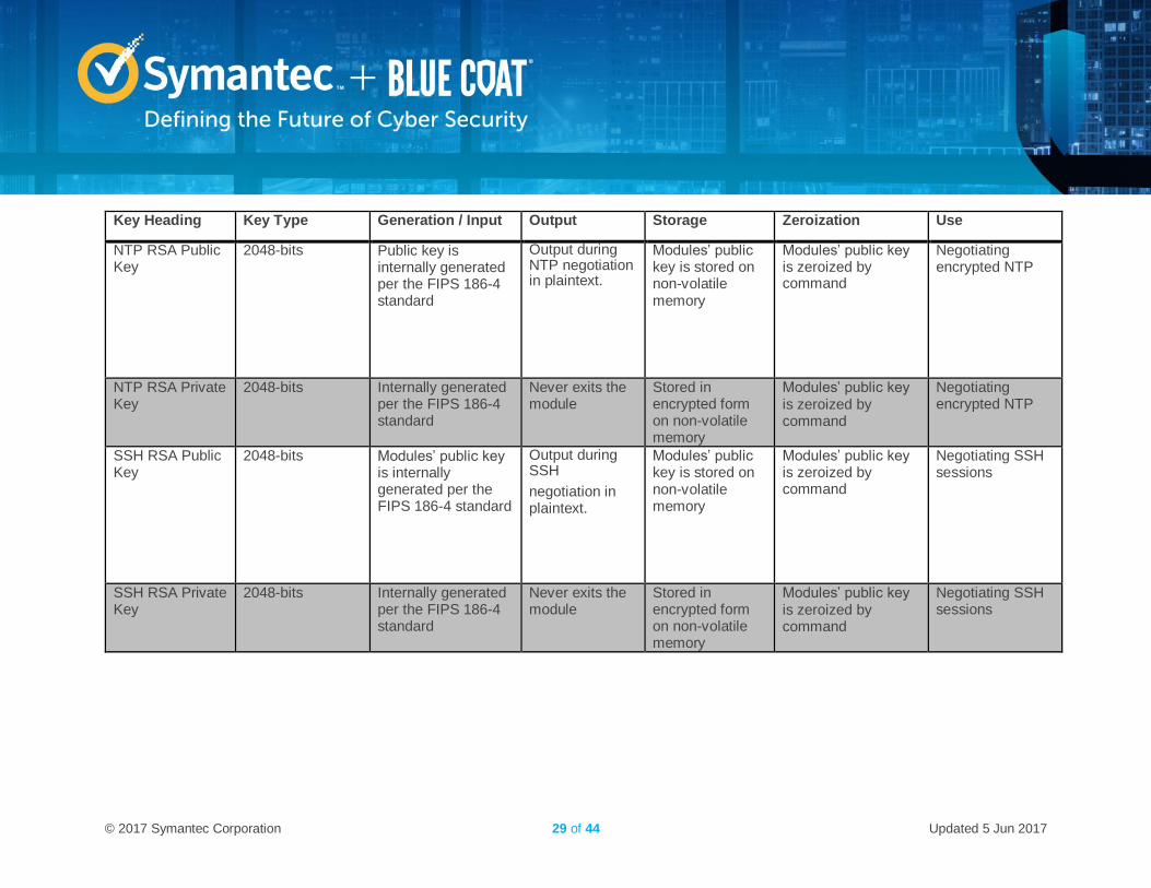
Key Heading Key Type Generation / Input Output Storage Zeroization Use
NTP RSA Public Key
2048-bits Public key is internally generated per the FIPS 186-4 standard
Output during NTP negotiation in plaintext.
Modules’ public key is stored on non-volatile memory
Modules’ public key is zeroized by command
Negotiating encrypted NTP
NTP RSA Private Key
2048-bits Internally generated per the FIPS 186-4 standard
Never exits the module
Stored in encrypted form on non-volatile memory
Modules’ public key is zeroized by command
Negotiating encrypted NTP
SSH RSA Public Key
2048-bits Modules’ public key is internally generated per the FIPS 186-4 standard
Output during SSH
negotiation in plaintext.
Modules’ public key is stored on non-volatile memory
Modules’ public key is zeroized by command
Negotiating SSH sessions
SSH RSA Private Key
2048-bits Internally generated per the FIPS 186-4 standard
Never exits the module
Stored in encrypted form on non-volatile memory
Modules’ public key is zeroized by command
Negotiating SSH sessions
© 2017 Symantec Corporation 30 of 44 Updated 5 Jun 2017
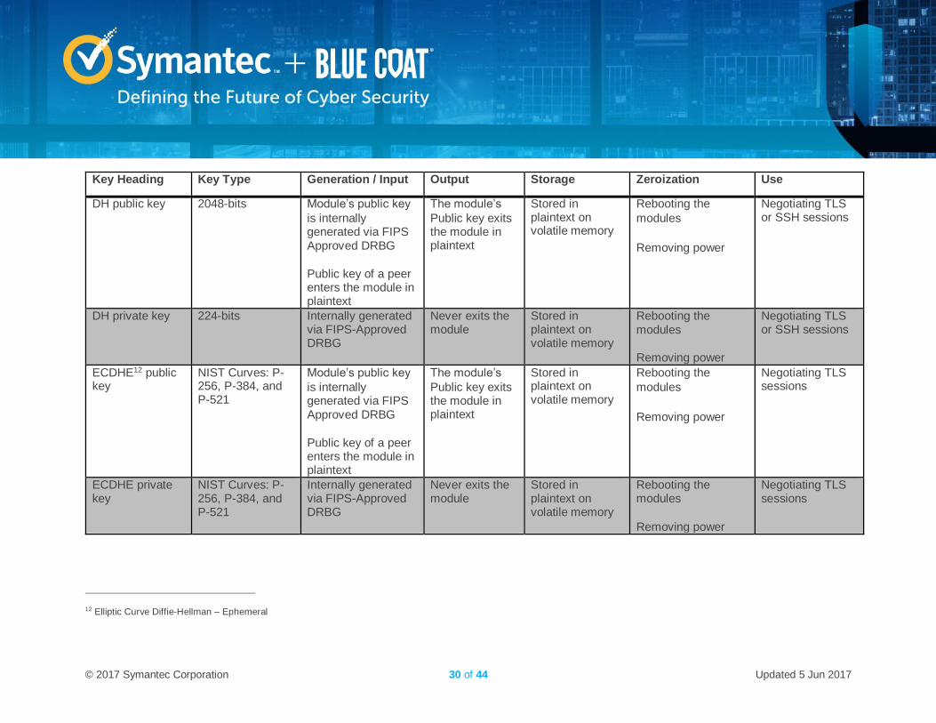
Key Heading Key Type Generation / Input Output Storage Zeroization Use
DH public key 2048-bits Module’s public key
is internally generated via FIPS Approved DRBG
Public key of a peer enters the module in plaintext
The module’s
Public key exits the module in plaintext
Stored in plaintext on volatile memory
Rebooting the
modules
Removing power
Negotiating TLS or SSH sessions
DH private key 224-bits Internally generated via FIPS-Approved DRBG
Never exits the module
Stored in plaintext on volatile memory
Rebooting the modules
Removing power
Negotiating TLS or SSH sessions
ECDHE12 public key
NIST Curves: P-256, P-384, and P-521
Module’s public key
is internally generated via FIPS Approved DRBG
Public key of a peer enters the module in plaintext
The module’s
Public key exits the module in plaintext
Stored in plaintext on volatile memory
Rebooting the
modules
Removing power
Negotiating TLS sessions
ECDHE private key
NIST Curves: P-256, P-384, and P-521
Internally generated via FIPS-Approved DRBG
Never exits the module
Stored in plaintext on volatile memory
Rebooting the modules
Removing power
Negotiating TLS sessions
12 Elliptic Curve Diffie-Hellman – Ephemeral
© 2017 Symantec Corporation 31 of 44 Updated 5 Jun 2017
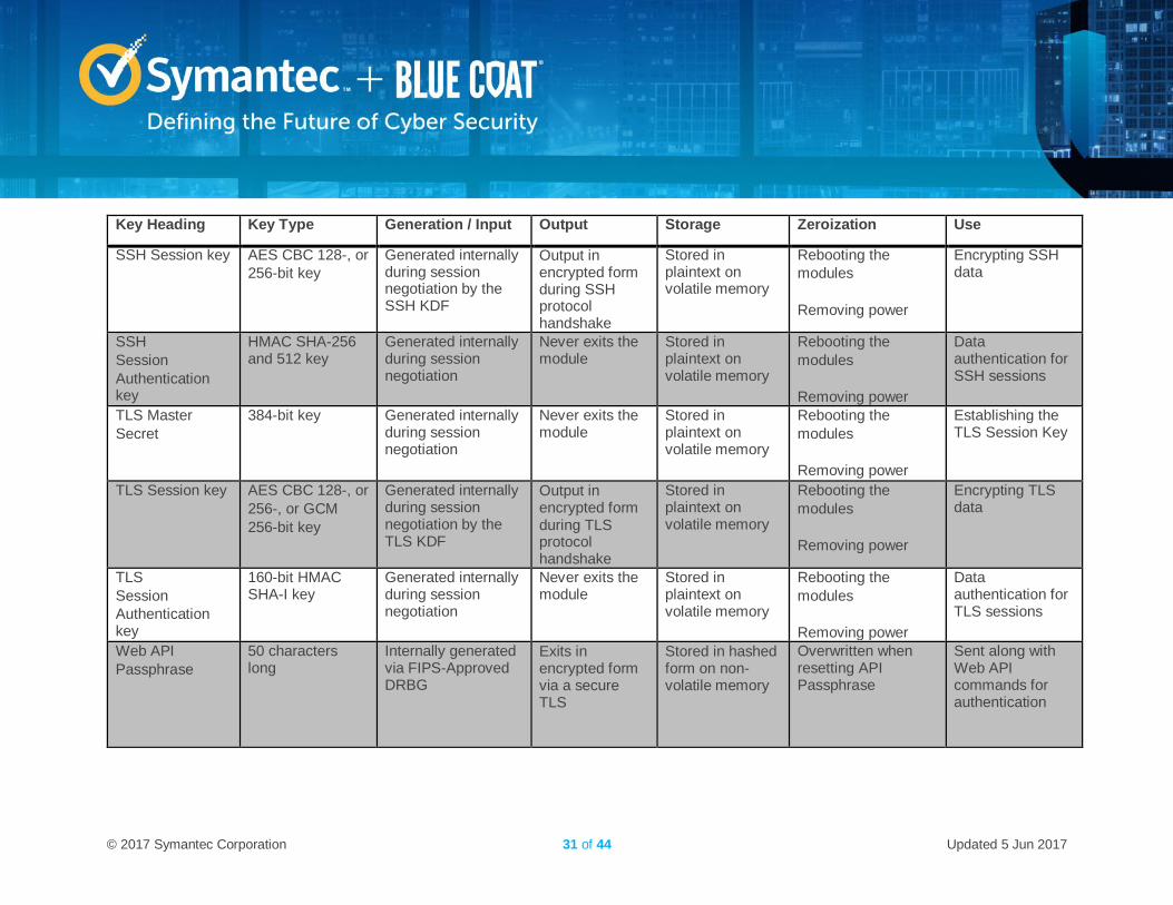
Key Heading Key Type Generation / Input Output Storage Zeroization Use
SSH Session key AES CBC 128-, or
256-bit key
Generated internally during session negotiation by the SSH KDF
Output in encrypted form during SSH protocol handshake
Stored in plaintext on volatile memory
Rebooting the
modules
Removing power
Encrypting SSH data
SSH
Session
Authentication key
HMAC SHA-256 and 512 key
Generated internally during session negotiation
Never exits the module
Stored in plaintext on volatile memory
Rebooting the
modules
Removing power
Data authentication for SSH sessions
TLS Master
Secret
384-bit key Generated internally during session negotiation
Never exits the module
Stored in plaintext on volatile memory
Rebooting the
modules
Removing power
Establishing the TLS Session Key
TLS Session key AES CBC 128-, or
256-, or GCM
256-bit key
Generated internally during session negotiation by the TLS KDF
Output in encrypted form during TLS protocol handshake
Stored in plaintext on volatile memory
Rebooting the
modules
Removing power
Encrypting TLS data
TLS
Session
Authentication key
160-bit HMAC SHA-I key
Generated internally during session negotiation
Never exits the module
Stored in plaintext on volatile memory
Rebooting the
modules
Removing power
Data authentication for TLS sessions
Web API
Passphrase
50 characters long
Internally generated via FIPS-Approved DRBG
Exits in encrypted form via a secure TLS
Stored in hashed form on non-volatile memory
Overwritten when resetting API Passphrase
Sent along with Web API commands for authentication
© 2017 Symantec Corporation 32 of 44 Updated 5 Jun 2017
Key Heading Key Type Generation / Input Output Storage Zeroization Use
CO
Password
User Password
Minimum of fifteen (15) characters long
Externally generated. Enters the module in encrypted form via a secure TLS or SSH session
Enters the module in
plaintext via a
directly attached
cable to the serial
port
Exits in encrypted form via a secure TLS session for external authentication
Stored in hashed form on non-volatile memory
Overwritten with a new password
Locally
authenticating a
CO
or User for
Web UI or CLI
SP 800-90A
HMAC_DRBG Seed
880-bit random number
Internally generated Never exits the module
Plaintext in
volatile
memory
Rebooting the
modules
Removing power
Seeding material
for
the SP800-90A
HMAC_DRBG
SP 800-90A
HMAC_DRBG
Entropy13
256-bit random number with derivation function
384-bit random number without derivation function
Internally generated Never exits the module
Plaintext in
volatile
memory
Rebooting the
modules
Removing power
Entropy material
for
the SP800-90A
HMAC_DRBG
SP 800-90A HMAC_DRBG key value
Internal state value
Internally generated Never Plaintext in
volatile
memory
Rebooting the
modules
Removing power
Used for the SP
800-90A
HMAC_DRBG
13 The Entropy required by the FIPS-Approved SP 800-90 HMAC_DRBG (with SHA-512) is supplied by the NDRNG
© 2017 Symantec Corporation 33 of 44 Updated 5 Jun 2017
Key Heading Key Type Generation / Input Output Storage Zeroization Use
SP 800-90A HMAC_DRBG V value
Internal state value
Internally generated Never exits the module
Plaintext in
volatile
memory
Rebooting the
modules
Removing power
Used for the SP
800-90A
HMAC_DRBG
NOTE: that some algorithms may be classified as deprecated, restricted, or legacy-use. Please consult NIST SP 800-131A for details.
© 2017 Symantec Corporation 34 of 44 Updated 5 Jun 2017
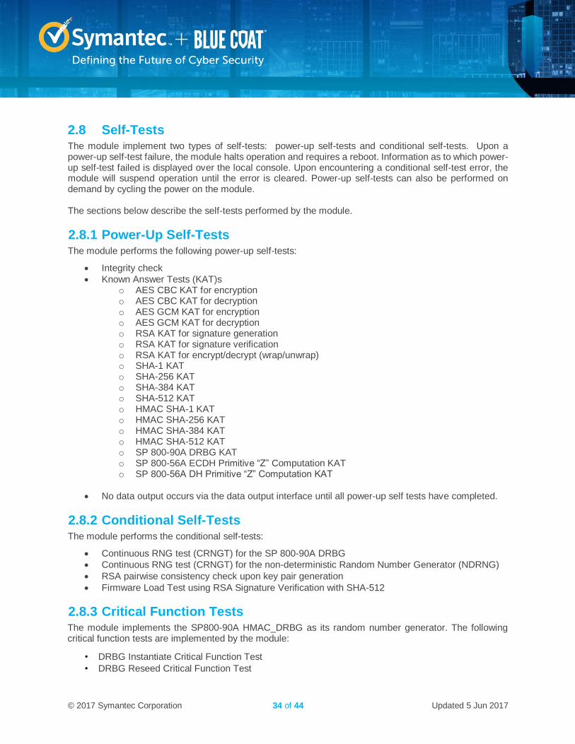
2.8 Self-Tests The module implement two types of self-tests: power-up self-tests and conditional self-tests. Upon a power-up self-test failure, the module halts operation and requires a reboot. Information as to which power-up self-test failed is displayed over the local console. Upon encountering a conditional self-test error, the module will suspend operation until the error is cleared. Power-up self-tests can also be performed on demand by cycling the power on the module. The sections below describe the self-tests performed by the module.
2.8.1 Power-Up Self-Tests The module performs the following power-up self-tests:
Integrity check
Known Answer Tests (KAT)s o AES CBC KAT for encryption o AES CBC KAT for decryption o AES GCM KAT for encryption o AES GCM KAT for decryption o RSA KAT for signature generation o RSA KAT for signature verification o RSA KAT for encrypt/decrypt (wrap/unwrap) o SHA-1 KAT o SHA-256 KAT o SHA-384 KAT o SHA-512 KAT o HMAC SHA-1 KAT o HMAC SHA-256 KAT o HMAC SHA-384 KAT o HMAC SHA-512 KAT o SP 800-90A DRBG KAT o SP 800-56A ECDH Primitive “Z” Computation KAT o SP 800-56A DH Primitive “Z” Computation KAT
No data output occurs via the data output interface until all power-up self tests have completed.
2.8.2 Conditional Self-Tests The module performs the conditional self-tests:
Continuous RNG test (CRNGT) for the SP 800-90A DRBG
Continuous RNG test (CRNGT) for the non-deterministic Random Number Generator (NDRNG)
RSA pairwise consistency check upon key pair generation
Firmware Load Test using RSA Signature Verification with SHA-512
2.8.3 Critical Function Tests The module implements the SP800-90A HMAC_DRBG as its random number generator. The following critical function tests are implemented by the module:
• DRBG Instantiate Critical Function Test
• DRBG Reseed Critical Function Test
© 2017 Symantec Corporation 35 of 44 Updated 5 Jun 2017
• DRBG Generate Critical Function Test
• DRBG Uninstantiate Critical Function Test
The module also performs a validity check on the installed license. If the license is not vaild, the module
will not operate.
2.9 Mitigation of Other Attacks This section is not applicable. The module does not claim to mitigate any attacks beyond the FIPS 140-2 Level 2 requirements for this validation.
© 2017 Symantec Corporation 36 of 44 Updated 5 Jun 2017
3. Secure Operation The module meets FIPS 140-2 Level 2 requirements. The sections below describe how to place and keep the module in FIPS-Approved mode of operation. The tamper seals and FIPS kit shall be installed for the module to operate in a FIPS Approved mode of operation
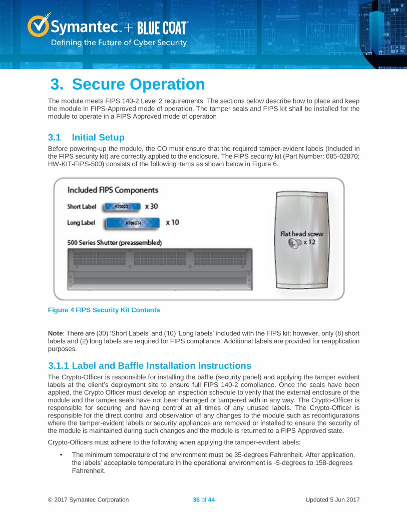
3.1 Initial Setup Before powering-up the module, the CO must ensure that the required tamper-evident labels (included in the FIPS security kit) are correctly applied to the enclosure. The FIPS security kit (Part Number: 085-02870; HW-KIT-FIPS-500) consists of the following items as shown below in Figure 6.
Figure 4 FIPS Security Kit Contents
Note: There are (30) ‘Short Labels’ and (10) ‘Long labels’ included with the FIPS kit; however, only (8) short labels and (2) long labels are required for FIPS compliance. Additional labels are provided for reapplication purposes.
3.1.1 Label and Baffle Installation Instructions The Crypto-Officer is responsible for installing the baffle (security panel) and applying the tamper evident labels at the client’s deployment site to ensure full FIPS 140-2 compliance. Once the seals have been applied, the Crypto Officer must develop an inspection schedule to verify that the external enclosure of the module and the tamper seals have not been damaged or tampered with in any way. The Crypto-Officer is responsible for securing and having control at all times of any unused labels. The Crypto-Officer is responsible for the direct control and observation of any changes to the module such as reconfigurations where the tamper-evident labels or security appliances are removed or installed to ensure the security of the module is maintained during such changes and the module is returned to a FIPS Approved state.
Crypto-Officers must adhere to the following when applying the tamper-evident labels:
• The minimum temperature of the environment must be 35-degrees Fahrenheit. After application,
the labels’ acceptable temperature in the operational environment is -5-degrees to 158-degrees
Fahrenheit.
© 2017 Symantec Corporation 37 of 44 Updated 5 Jun 2017
• Do not touch the adhesive side of the label. This disrupts the integrity of the adhesive. If a label is
removed from a surface, the image is destroyed and the label shows tamper-evident text as
evidence. If you accidently touch the adhesive side, discard that label and apply another one.
Label application tips:
• Apply skin moisturizer on your fingers before handling.
• Use a rubber fingertip to partially remove the label from its backing.
• After applying the labels, allow at least 24 hours for the label adhesive to cure.
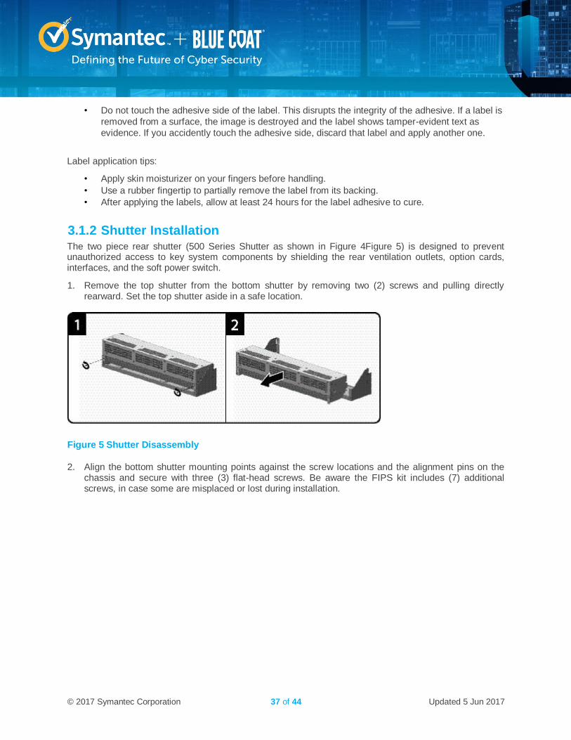
3.1.2 Shutter Installation The two piece rear shutter (500 Series Shutter as shown in Figure 4Figure 5) is designed to prevent unauthorized access to key system components by shielding the rear ventilation outlets, option cards, interfaces, and the soft power switch.
1. Remove the top shutter from the bottom shutter by removing two (2) screws and pulling directly rearward. Set the top shutter aside in a safe location.
Figure 5 Shutter Disassembly
2. Align the bottom shutter mounting points against the screw locations and the alignment pins on the chassis and secure with three (3) flat-head screws. Be aware the FIPS kit includes (7) additional screws, in case some are misplaced or lost during installation.

© 2017 Symantec Corporation 38 of 44 Updated 5 Jun 2017
Figure 6 Lower Shutter Installation
3. Rack mount the appliance. Refer to the 500 Series Maintenance and Upgrade Guide for instructions and safety information on rack-mounting the appliance.
4. Reinstall the appliance network and other interconnect cables to their respective locations
Note: All network and interconnect cables must installed at this time to prevent reopening of the shutters and subsequent reapplication of the security labels.
5. Route the network cables through the cable management anchors to prevent cables from obstructing airflow.
6. Install the top shutter by aligning the notches with the raised pins on the appliance and secure with two (2) flat-head screws. Be aware the FIPS kit includes (7) additional screws, in case some are misplaced or lost during installation.
Figure 7 Upper Shutter Installation
3.1.3 Label Application The FIPS compliant blue labels are applied over key areas of the chassis to provide tamper-evident security. If the labels are removed after being affixed to a surface, the image self-destructs and leaves a
© 2017 Symantec Corporation 39 of 44 Updated 5 Jun 2017
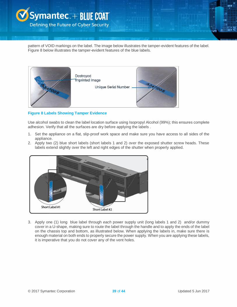
pattern of VOID markings on the label. The image below illustrates the tamper-evident features of the label. Figure 8 below illustrates the tamper-evident features of the blue labels.
Figure 8 Labels Showing Tamper Evidence
Use alcohol swabs to clean the label location surface using Isopropyl Alcohol (99%); this ensures complete adhesion. Verify that all the surfaces are dry before applying the labels .
1. Set the appliance on a flat, slip-proof work space and make sure you have access to all sides of the appliance.
2. Apply two (2) blue short labels (short labels 1 and 2) over the exposed shutter screw heads. These labels extend slightly over the left and right edges of the shutter when properly applied.
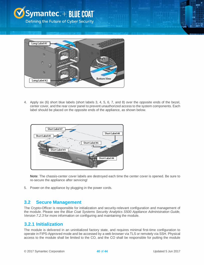
3. Apply one (1) long blue label through each power supply unit (long labels 1 and 2) and/or dummy
cover in a U-shape, making sure to route the label through the handle and to apply the ends of the label on the chassis top and bottom, as illustrated below. When applying the labels in, make sure there is enough material on both ends to properly secure the power supply. When you are applying these labels, it is imperative that you do not cover any of the vent holes.
© 2017 Symantec Corporation 40 of 44 Updated 5 Jun 2017
4. Apply six (6) short blue labels (short labels 3, 4, 5, 6, 7, and 8) over the opposite ends of the bezel,
center cover, and the rear cover panel to prevent unauthorized access to the system components. Each label should be placed on the opposite ends of the appliance, as shown below.
Note: The chassis-center cover labels are destroyed each time the center cover is opened. Be sure to re-secure the appliance after servicing!
5. Power-on the appliance by plugging in the power cords.
3.2 Secure Management The Crypto-Officer is responsible for initialization and security-relevant configuration and management of the module. Please see the Blue Coat Systems Security Analytics S500 Appliance Administration Guide, Version 7.2.3 for more information on configuring and maintaining the module.
3.2.1 Initialization The module is delivered in an uninitialized factory state, and requires minimal first-time configuration to operate in FIPS-Approved mode and be accessed by a web browser via TLS or remotely via SSH. Physical access to the module shall be limited to the CO, and the CO shall be responsible for putting the module
© 2017 Symantec Corporation 41 of 44 Updated 5 Jun 2017
into the Approved mode. Note, these same steps in this section shall be followed after the zeroization command is entered.
The process of establishing the initial configuration is described below.
1. Connect to the serial interface with the admin account (admin | Solera).
2. Set the IP address and default gateway using sudo ifconfig and sudo route. 3. Login to the Web Interface with the admin account. 4. Re-enter the IP address, netmask, and gateway values. 5. Specify at least one DNS server. 6. Set the correct date, time, and zone for the appliance: MM/DD/YYYY hh:ii:ss. 7. Set the passwords for the root and admin accounts. The default password-strength requirements are:
14 characters, digit, uppercase, lowercase, other character. NOTE: After entering FIPS mode, the root account is disabled.
8. Click Save. 9. Enter the license key in the space provided, send the request, and then select the license for the
appliance. The appliance automatically reboots. 10. When the appliance has rebooted, log in to the web interface using the admin account and the new
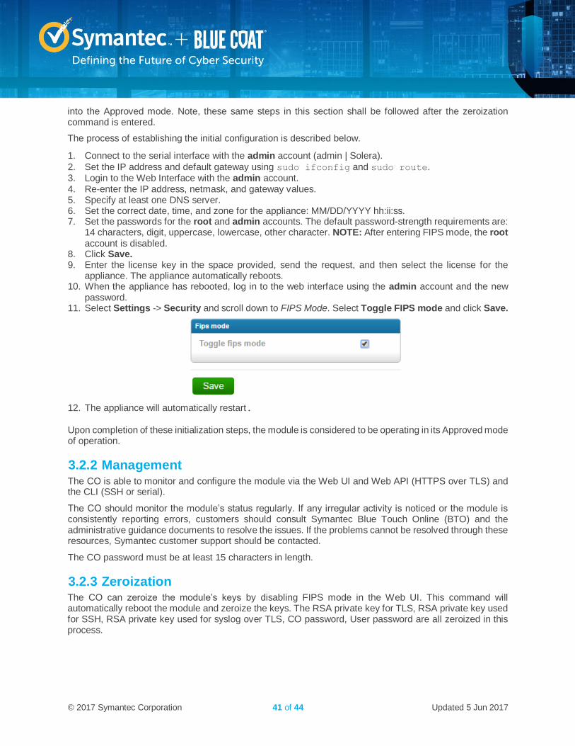
password. 11. Select Settings -> Security and scroll down to FIPS Mode. Select Toggle FIPS mode and click Save.
12. The appliance will automatically restart.
Upon completion of these initialization steps, the module is considered to be operating in its Approved mode of operation.
3.2.2 Management The CO is able to monitor and configure the module via the Web UI and Web API (HTTPS over TLS) and the CLI (SSH or serial).
The CO should monitor the module’s status regularly. If any irregular activity is noticed or the module is consistently reporting errors, customers should consult Symantec Blue Touch Online (BTO) and the administrative guidance documents to resolve the issues. If the problems cannot be resolved through these resources, Symantec customer support should be contacted.
The CO password must be at least 15 characters in length.
3.2.3 Zeroization The CO can zeroize the module’s keys by disabling FIPS mode in the Web UI. This command will automatically reboot the module and zeroize the keys. The RSA private key for TLS, RSA private key used for SSH, RSA private key used for syslog over TLS, CO password, User password are all zeroized in this process.
© 2017 Symantec Corporation 42 of 44 Updated 5 Jun 2017
In addition, rebooting the module causes all temporary keys stored in volatile memory (SSH Session key, TLS session key, DRBG entropy values, and NDRNG entropy values) to be zeroized. The CO must wait until the module has successfully rebooted in order to verify that zeroization has completed.
3.3 User Guidance The User is only able to access the module remotely via SSH (CLI) or HTTPS (Web UI). The User must change his or her password at the initial login. The User must be diligent to pick strong passwords (alphanumeric with minimum 15 characters) that will not be easily guessed, and must not reveal their password to anyone. Additionally, the User should be careful to protect any secret/private keys in their possession, such as TLS or SSH session keys. The User should report to the CO if any irregular activity is noticed.
3.4 Non-Approved Mode When initialized and configured according to the Crypto-Officer guidance in this Non-Proprietary Security Policy, the module does not support a non-Approved mode of operation.
© 2017 Symantec Corporation 43 of 44 Updated 5 Jun 2017
© 2017 Symantec Corporation All rights reserved. Symantec, the Symantec logos, ProxySG, PacketShaper, CacheFlow, IntelligenceCenter, CacheOS,
CachePulse, Crossbeam, K9, the K9 logo, DRTR, MACH5, PacketWise, PolicyCenter, ProxyAV, ProxyClient, SGOS, WebPulse, Solera Networks, the Solera Networks logos, DeepSee, “See Everything. Know Everything.”, “Security Empowers Business”, and BlueTouch are registered trademarks or trademarks of Symantec Corporation or its affiliates in the U.S. and certain other countries. This list may not be complete, and the absence of a trademark from this list does not mean it is not a trademark of Symantec or that Symantec has stopped using the trademark. All other trademarks mentioned in this document owned by third parties are the property of their respective owners. This document is for informational purposes only. Symantec makes no warranties, express, implied, or statutory, as to the information in this document.
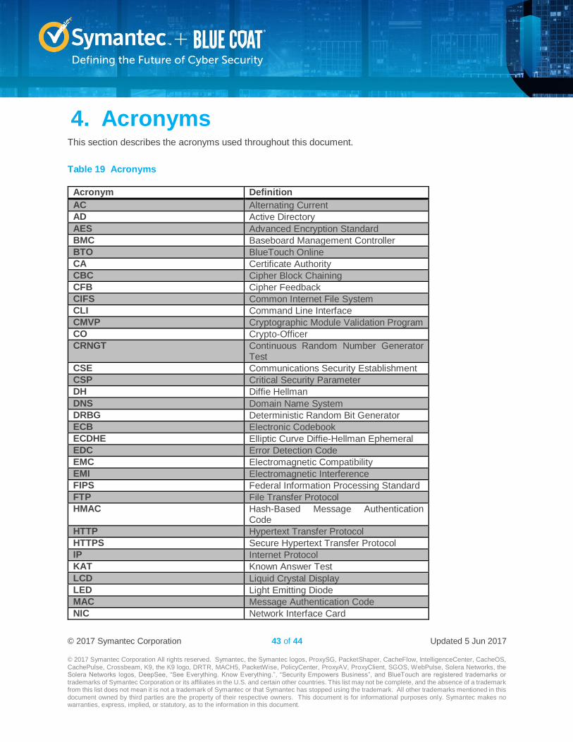
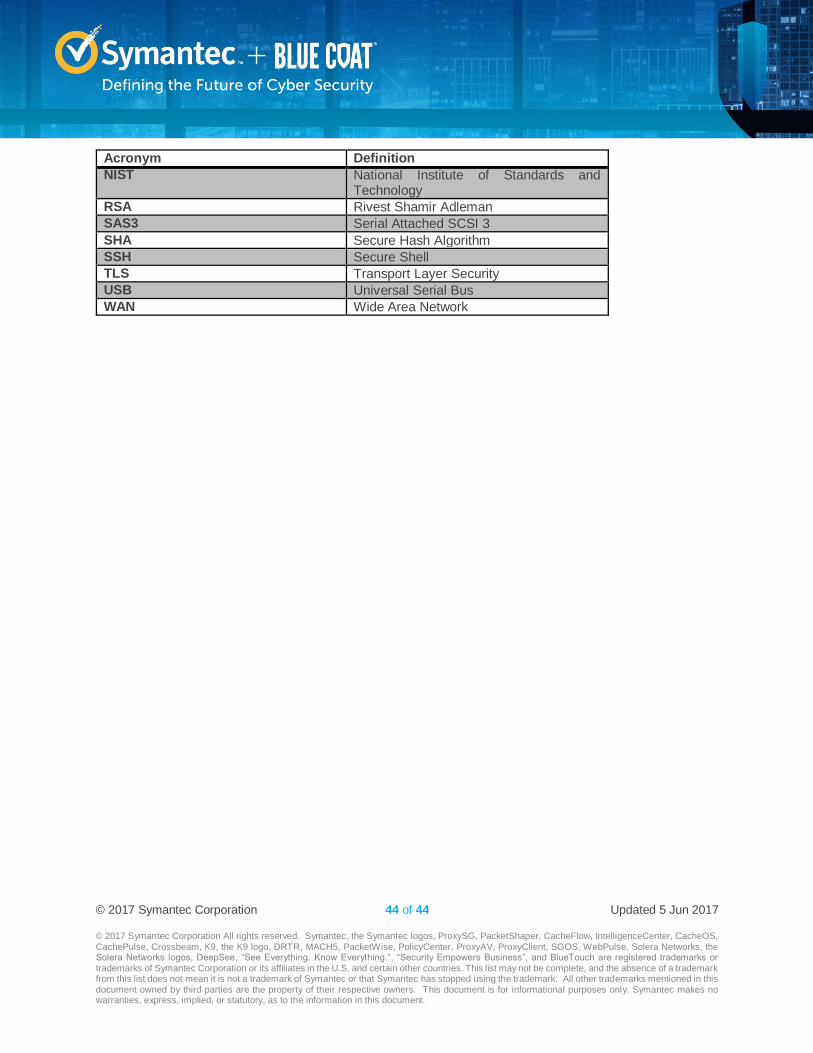
4. Acronyms This section describes the acronyms used throughout this document.
Table 19 Acronyms
Acronym Definition
AC Alternating Current
AD Active Directory
AES Advanced Encryption Standard
BMC Baseboard Management Controller
BTO BlueTouch Online
CA Certificate Authority
CBC Cipher Block Chaining
CFB Cipher Feedback
CIFS Common Internet File System
CLI Command Line Interface
CMVP Cryptographic Module Validation Program
CO Crypto-Officer
CRNGT Continuous Random Number Generator Test
CSE Communications Security Establishment
CSP Critical Security Parameter
DH Diffie Hellman
DNS Domain Name System
DRBG Deterministic Random Bit Generator
ECB Electronic Codebook
ECDHE Elliptic Curve Diffie-Hellman Ephemeral
EDC Error Detection Code
EMC Electromagnetic Compatibility
EMI Electromagnetic Interference
FIPS Federal Information Processing Standard
FTP File Transfer Protocol
HMAC Hash-Based Message Authentication Code
HTTP Hypertext Transfer Protocol
HTTPS Secure Hypertext Transfer Protocol
IP Internet Protocol
KAT Known Answer Test
LCD Liquid Crystal Display
LED Light Emitting Diode
MAC Message Authentication Code
NIC Network Interface Card
© 2017 Symantec Corporation 44 of 44 Updated 5 Jun 2017
© 2017 Symantec Corporation All rights reserved. Symantec, the Symantec logos, ProxySG, PacketShaper, CacheFlow, IntelligenceCenter, CacheOS,
CachePulse, Crossbeam, K9, the K9 logo, DRTR, MACH5, PacketWise, PolicyCenter, ProxyAV, ProxyClient, SGOS, WebPulse, Solera Networks, the Solera Networks logos, DeepSee, “See Everything. Know Everything.”, “Security Empowers Business”, and BlueTouch are registered trademarks or trademarks of Symantec Corporation or its affiliates in the U.S. and certain other countries. This list may not be complete, and the absence of a trademark from this list does not mean it is not a trademark of Symantec or that Symantec has stopped using the trademark. All other trademarks mentioned in this document owned by third parties are the property of their respective owners. This document is for informational purposes only. Symantec makes no warranties, express, implied, or statutory, as to the information in this document.
Acronym Definition
NIST National Institute of Standards and Technology
RSA Rivest Shamir Adleman
SAS3 Serial Attached SCSI 3
SHA Secure Hash Algorithm
SSH Secure Shell
TLS Transport Layer Security
USB Universal Serial Bus
WAN Wide Area Network