Embed Size (px)
Citation preview
8/12/2019 SYM Mio50 Service Manual 000
http://slidepdf.com/reader/full/sym-mio50-service-manual-000 1/215
M io 5 0 / 1 0 0
SERVICE MANUAL
FORWARD
HOW TO USE THIS MANUAL
CONTENTS
Mechanism Illustrations
8/12/2019 SYM Mio50 Service Manual 000
http://slidepdf.com/reader/full/sym-mio50-service-manual-000 2/215
Forward
This service manual contains the technical data of each component inspection and
repair for the SANYANG Mio 50 / 100 scooters. The manual is shown with
illustrations and focused on “Service Procedures”, “Operation Key Points”, and
“Inspection Adjustment” so that provides technician with service guidelines.
If the style and construction of the scooter, Mio 50 / 100, are different from that of
the photos, pictures shown in this manual, the actual vehicle shall prevail.
Specifications are subject to change without notice.
Service Department
SANYANG INDUSTRY CO., LTD.
Homepage Contents
8/12/2019 SYM Mio50 Service Manual 000
http://slidepdf.com/reader/full/sym-mio50-service-manual-000 3/215
How To Use This Manual
This service manual describes basic information of different system parts and
system inspection & service for SANYANG Mio 50 / 100 scooters. In addition,
please refer to the manual contents in detailed for the model you serviced in
inspection and adjustment.
The first chapter covers general information and trouble diagnosis.
The second chapter covers service maintenance information and special tools
manual.
The third to the 11th chapters cover engine and driving systems.
The 12th chapter is cooling system.
The 13th to the 16th chapter is contained the parts set of assembly frame body.
The 17th chapter is electrical equipment.
The 18th chapter is wiring diagram.
Please see index of content for quick having the special parts and system
information.
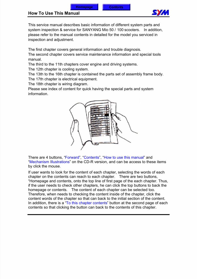
There are 4 buttons, “Forward”, “Contents”, “How to use this manual” and
“Mechanism Illustrations” on the CD-R version, and can be access to these itemsby click the mouse.
If user wants to look for the content of each chapter, selecting the words of eachchapter on the contents can reach to each chapter. There are two buttons,“Homepage and contents, onto the top line of first page of the each chapter. Thus,if the user needs to check other chapters, he can click the top buttons to back thehomepage or contents. The content of each chapter can be selected too.Therefore, when needs to checking the content inside of the chapter, click thecontent words of the chapter so that can back to the initial section of the content.
In addition, there is a “To this chapter contents” button at the second page of eachcontents so that clicking the button can back to the contents of this chapter.
Homepage Contents
8/12/2019 SYM Mio50 Service Manual 000
http://slidepdf.com/reader/full/sym-mio50-service-manual-000 4/215
Contents
Page Content Index
1-1 ~ 1-18 General Information 1
2-1 ~ 2-18 Service Maintenance Information 2
3-1 ~ 3-8 Lubrication System 3
4-1 ~ 4-12 Fuel System 4
5-1 ~ 5-8 Engine Removal 5
6-1 ~ 6-18
Cylinder Head/Valve6
7-1 ~ 7-8 Cylinder/Piston 7
8-1 ~ 8-14 “V” Type Belt Driving System / Kick-Starter 8
9-1 ~ 9-8 Final Driving Mechanism 9
10-1 ~ 10-8 Alternator 10
11-1 ~ 11-8 Crankshaft / Crankcase 11
12-1 ~ 12-16 Body Cover 12
13-1 ~ 13-14 Brake 13
14-1 ~ 14-12 Steering / Front Wheel / Front Cushion 14
15-1 ~ 15-4 Rear Wheel / Rear Cushion 15
16-1 ~ 16-26 Electrical Equipment 16
17-1 ~ 17-8 Emission Control System 17
18-1 ~ 18-2 Electrical Diagram 18
Homepage
8/12/2019 SYM Mio50 Service Manual 000
http://slidepdf.com/reader/full/sym-mio50-service-manual-000 5/215
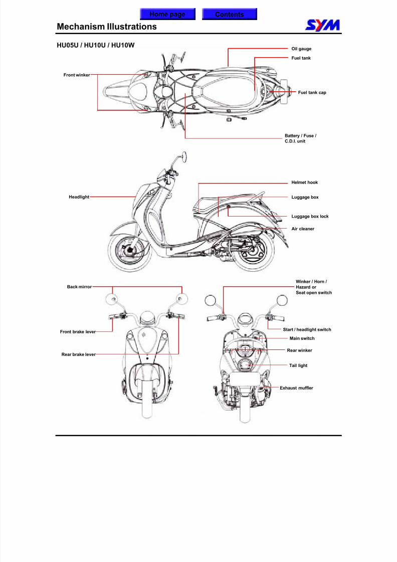
Mechanism Illustrations
HU05U / HU10U / HU10W
Exhaust muffler
Home page Contents
Air cleaner
Fuel tank cap
Start / headlight switch
Battery / Fuse /
C.D.I. unit
Front brake lever
Rear brake lever
Back mirror
Luggage box
Luggage box lock
Helmet hook
Winker / Horn /
Hazard or
Seat open switch
Front winker
Headlight
Tail light
Main switch
Oil gauge
Fuel tank
Rear winker
8/12/2019 SYM Mio50 Service Manual 000
http://slidepdf.com/reader/full/sym-mio50-service-manual-000 6/215
1. General Information
1-1
Symbols and Marks····························1-1
General Safety····································1-2
Service Precautions···························1-3
Specifications·····································1-9
Torque Values ···································· 1-11
Troubles Diagnosis···························· 1-13
Lubrication Points ····························· 1-17
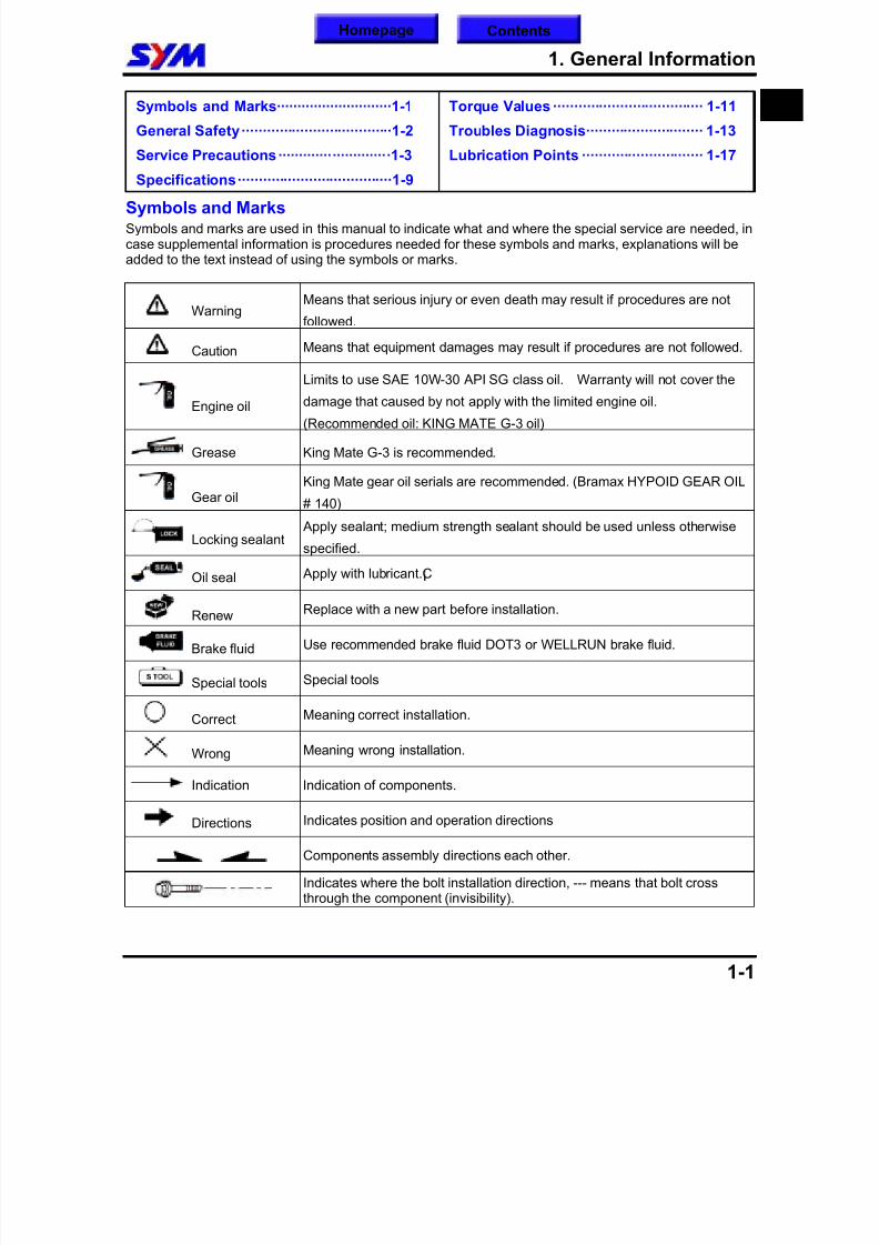
Symbols and MarksSymbols and marks are used in this manual to indicate what and where the special service are needed, incase supplemental information is procedures needed for these symbols and marks, explanations will beadded to the text instead of using the symbols or marks.
WarningMeans that serious injury or even death may result if procedures are not
followed.
Caution Means that equipment damages may result if procedures are not followed.
Engine oil
Limits to use SAE 10W-30 API SG class oil. Warranty will not cover the
damage that caused by not apply with the limited engine oil.
(Recommended oil: KING MATE G-3 oil)
Grease King Mate G-3 is recommended.
Gear oilKing Mate gear oil serials are recommended. (Bramax HYPOID GEAR OIL
# 140)
Locking sealant
Apply sealant; medium strength sealant should be used unless otherwise
specified.
Oil seal Apply with lubricant.¡C
Renew Replace with a new part before installation.
Brake fluid Use recommended brake fluid DOT3 or WELLRUN brake fluid.
Special tools Special tools
CorrectMeaning correct installation.
Wrong Meaning wrong installation.
Indication Indication of components.
Directions Indicates position and operation directions
Components assembly directions each other.
Indicates where the bolt installation direction, --- means that bolt crossthrough the component (invisibility).
1
Homepage Contents
8/12/2019 SYM Mio50 Service Manual 000
http://slidepdf.com/reader/full/sym-mio50-service-manual-000 7/215
1. General Information
1-2
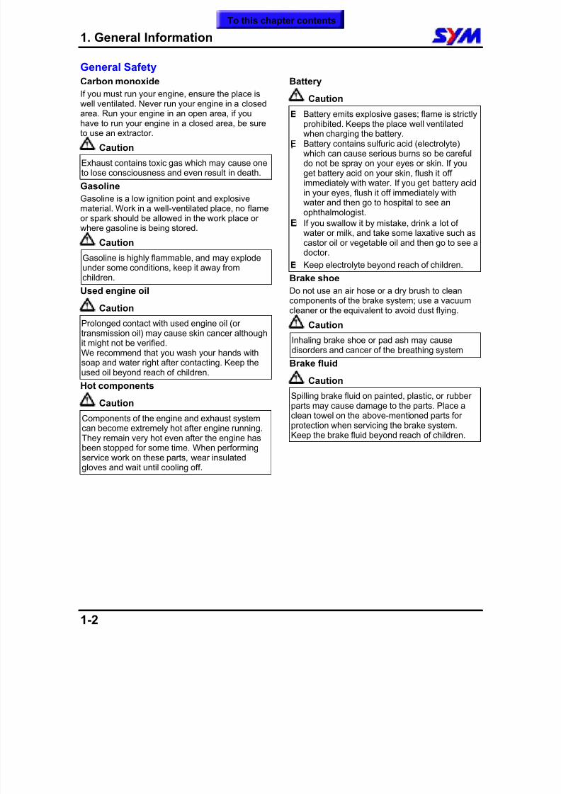
General Safety
Carbon monoxide
If you must run your engine, ensure the place iswell ventilated. Never run your engine in a closed
area. Run your engine in an open area, if youhave to run your engine in a closed area, be sureto use an extractor.
Caution
Exhaust contains toxic gas which may cause oneto lose consciousness and even result in death.
Gasoline Gasoline is a low ignition point and explosivematerial. Work in a well-ventilated place, no flameor spark should be allowed in the work place or
where gasoline is being stored. Caution
Gasoline is highly flammable, and may explodeunder some conditions, keep it away fromchildren.
Used engine oil
Caution
Prolonged contact with used engine oil (ortransmission oil) may cause skin cancer although
it might not be verified.We recommend that you wash your hands withsoap and water right after contacting. Keep theused oil beyond reach of children.
Hot components
Caution
Components of the engine and exhaust systemcan become extremely hot after engine running.They remain very hot even after the engine hasbeen stopped for some time. When performingservice work on these parts, wear insulatedgloves and wait until cooling off.
Battery
Caution
¡E Battery emits explosive gases; flame is strictlyprohibited. Keeps the place well ventilatedwhen charging the battery.
¡E Battery contains sulfuric acid (electrolyte)which can cause serious burns so be carefuldo not be spray on your eyes or skin. If youget battery acid on your skin, flush it offimmediately with water. If you get battery acidin your eyes, flush it off immediately withwater and then go to hospital to see anophthalmologist.
¡E If you swallow it by mistake, drink a lot of
water or milk, and take some laxative such ascastor oil or vegetable oil and then go to see adoctor.
¡E Keep electrolyte beyond reach of children.
Brake shoe Do not use an air hose or a dry brush to cleancomponents of the brake system; use a vacuumcleaner or the equivalent to avoid dust flying.
Caution
Inhaling brake shoe or pad ash may causedisorders and cancer of the breathing system Brake fluid
Caution
Spilling brake fluid on painted, plastic, or rubberparts may cause damage to the parts. Place aclean towel on the above-mentioned parts forprotection when servicing the brake system.Keep the brake fluid beyond reach of children.
To this chapter contents
8/12/2019 SYM Mio50 Service Manual 000
http://slidepdf.com/reader/full/sym-mio50-service-manual-000 8/215
1. General Information
1-3
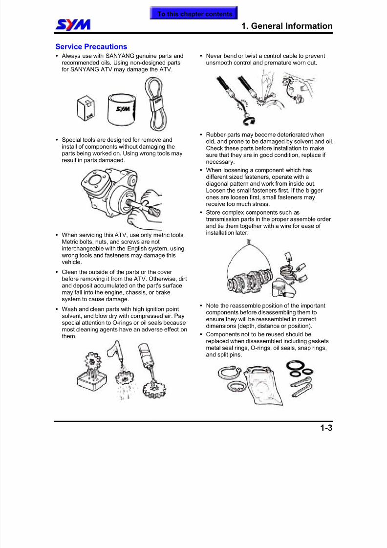
Service Precautions Always use with SANYANG genuine parts and
recommended oils. Using non-designed partsfor SANYANG ATV may damage the ATV.
Special tools are designed for remove andinstall of components without damaging theparts being worked on. Using wrong tools may
result in parts damaged.
When servicing this ATV, use only metric tools.Metric bolts, nuts, and screws are notinterchangeable with the English system, usingwrong tools and fasteners may damage thisvehicle.
Clean the outside of the parts or the coverbefore removing it from the ATV. Otherwise, dirtand deposit accumulated on the part's surfacemay fall into the engine, chassis, or brakesystem to cause damage.
Wash and clean parts with high ignition pointsolvent, and blow dry with compressed air. Payspecial attention to O-rings or oil seals becausemost cleaning agents have an adverse effect onthem.
Never bend or twist a control cable to preventunsmooth control and premature worn out.
Rubber parts may become deteriorated whenold, and prone to be damaged by solvent and oil.Check these parts before installation to makesure that they are in good condition, replace ifnecessary.
When loosening a component which hasdifferent sized fasteners, operate with adiagonal pattern and work from inside out.Loosen the small fasteners first. If the biggerones are loosen first, small fasteners mayreceive too much stress.
Store complex components such astransmission parts in the proper assemble orderand tie them together with a wire for ease ofinstallation later.
Note the reassemble position of the importantcomponents before disassembling them to
ensure they will be reassembled in correctdimensions (depth, distance or position).
Components not to be reused should bereplaced when disassembled including gasketsmetal seal rings, O-rings, oil seals, snap rings,and split pins.
To this chapter contents
8/12/2019 SYM Mio50 Service Manual 000
http://slidepdf.com/reader/full/sym-mio50-service-manual-000 9/215
1. General Information
1-4
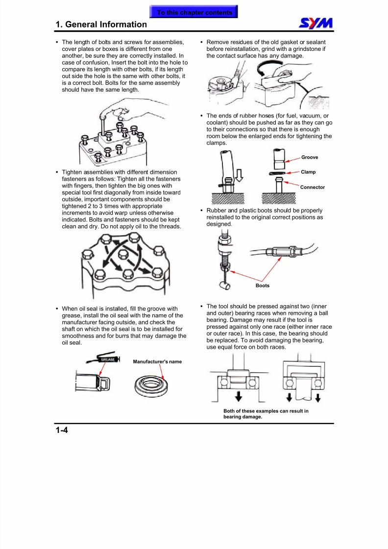
The length of bolts and screws for assemblies,cover plates or boxes is different from oneanother, be sure they are correctly installed. Incase of confusion, Insert the bolt into the hole tocompare its length with other bolts, if its lengthout side the hole is the same with other bolts, itis a correct bolt. Bolts for the same assemblyshould have the same length.
Tighten assemblies with different dimensionfasteners as follows: Tighten all the fastenerswith fingers, then tighten the big ones withspecial tool first diagonally from inside towardoutside, important components should betightened 2 to 3 times with appropriateincrements to avoid warp unless otherwiseindicated. Bolts and fasteners should be keptclean and dry. Do not apply oil to the threads.
When oil seal is installed, fill the groove withgrease, install the oil seal with the name of themanufacturer facing outside, and check theshaft on which the oil seal is to be installed forsmoothness and for burrs that may damage theoil seal.
Remove residues of the old gasket or sealantbefore reinstallation, grind with a grindstone ifthe contact surface has any damage.
The ends of rubber hoses (for fuel, vacuum, orcoolant) should be pushed as far as they can goto their connections so that there is enoughroom below the enlarged ends for tightening theclamps.
Rubber and plastic boots should be properlyreinstalled to the original correct positions asdesigned.
The tool should be pressed against two (innerand outer) bearing races when removing a ball
bearing. Damage may result if the tool ispressed against only one race (either inner raceor outer race). In this case, the bearing shouldbe replaced. To avoid damaging the bearing,use equal force on both races.
Both of these examples can result inbearing damage.
Manufacturer's name
Groove
Clamp
Connector
Boots
To this chapter contents
8/12/2019 SYM Mio50 Service Manual 000
http://slidepdf.com/reader/full/sym-mio50-service-manual-000 10/215
1. General Information
1-5
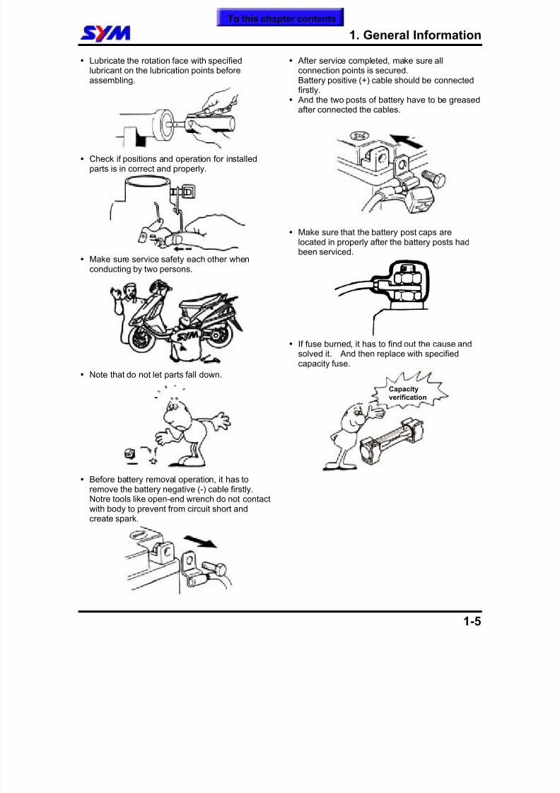
Lubricate the rotation face with specifiedlubricant on the lubrication points beforeassembling.
Check if positions and operation for installedparts is in correct and properly.
Make sure service safety each other whenconducting by two persons.
Note that do not let parts fall down.
Before battery removal operation, it has toremove the battery negative (-) cable firstly.Notre tools like open-end wrench do not contactwith body to prevent from circuit short andcreate spark.
After service completed, make sure allconnection points is secured.Battery positive (+) cable should be connectedfirstly.
And the two posts of battery have to be greasedafter connected the cables.
Make sure that the battery post caps arelocated in properly after the battery posts hadbeen serviced.
If fuse burned, it has to find out the cause andsolved it. And then replace with specifiedcapacity fuse.
Capacityverification
To this chapter contents
8/12/2019 SYM Mio50 Service Manual 000
http://slidepdf.com/reader/full/sym-mio50-service-manual-000 11/215
1. General Information
1-6
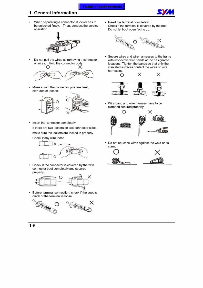
When separating a connector, it locker has tobe unlocked firstly. Then, conduct the serviceoperation.
Do not pull the wires as removing a connectoror wires. Hold the connector body.
Make sure if the connector pins are bent,extruded or loosen.
Insert the connector completely.
If there are two lockers on two connector sides,
make sure the lockers are locked in properly.
Check if any wire loose.
Check if the connector is covered by the twin
connector boot completely and securedproperly.
Before terminal connection, check if the boot iscrack or the terminal is loose.
Insert the terminal completely.Check if the terminal is covered by the boot.Do not let boot open facing up.
Secure wires and wire harnesses to the framewith respective wire bands at the designatedlocations. Tighten the bands so that only theinsulated surfaces contact the wires or wireharnesses.
Wire band and wire harness have to beclamped secured properly.
Do not squeeze wires against the weld or itsclamp.
To this chapter contents
8/12/2019 SYM Mio50 Service Manual 000
http://slidepdf.com/reader/full/sym-mio50-service-manual-000 12/215
1. General Information
1-7
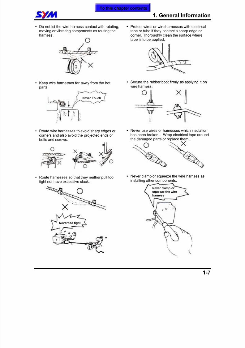
Do not let the wire harness contact with rotating,moving or vibrating components as routing theharness.
Keep wire harnesses far away from the hotparts.
Route wire harnesses to avoid sharp edges orcorners and also avoid the projected ends ofbolts and screws.
Route harnesses so that they neither pull tootight nor have excessive slack.
Protect wires or wire harnesses with electricaltape or tube if they contact a sharp edge orcorner. Thoroughly clean the surface wheretape is to be applied.
Secure the rubber boot firmly as applying it onwire harness.
Never use wires or harnesses which insulationhas been broken. Wrap electrical tape aroundthe damaged parts or replace them.
Never clamp or squeeze the wire harness asinstalling other components.
Never Touch
Never too tight
Never clamp orsqueeze the wireharness
To this chapter contents
8/12/2019 SYM Mio50 Service Manual 000
http://slidepdf.com/reader/full/sym-mio50-service-manual-000 13/215
1. General Information
1-8
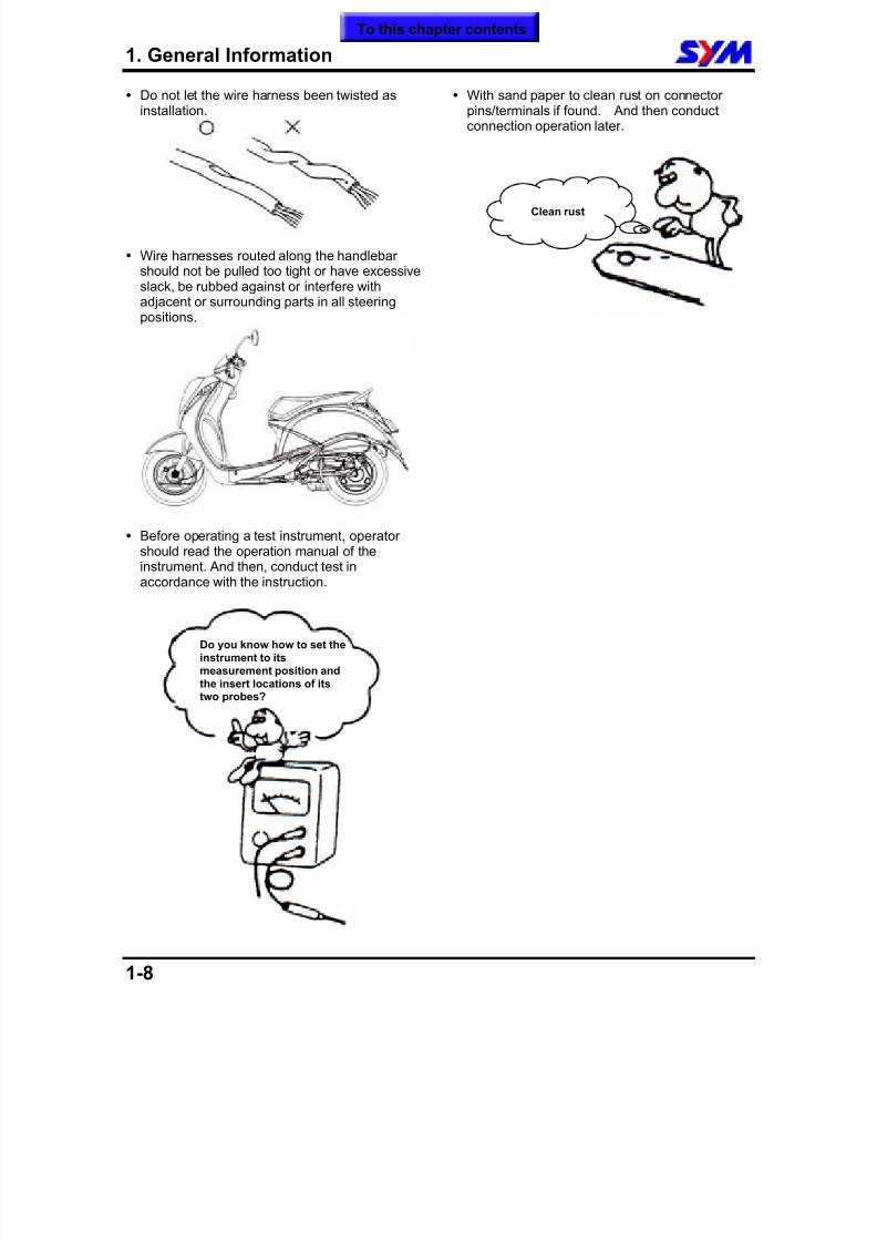
Do not let the wire harness been twisted asinstallation.
Wire harnesses routed along the handlebarshould not be pulled too tight or have excessiveslack, be rubbed against or interfere withadjacent or surrounding parts in all steeringpositions.
Before operating a test instrument, operatorshould read the operation manual of theinstrument. And then, conduct test inaccordance with the instruction.
With sand paper to clean rust on connectorpins/terminals if found. And then conductconnection operation later.
Do you know how to set theinstrument to itsmeasurement position andthe insert locations of itstwo probes?
Clean rust
To this chapter contents
8/12/2019 SYM Mio50 Service Manual 000
http://slidepdf.com/reader/full/sym-mio50-service-manual-000 14/215
1. General Information
1-9
Specifications
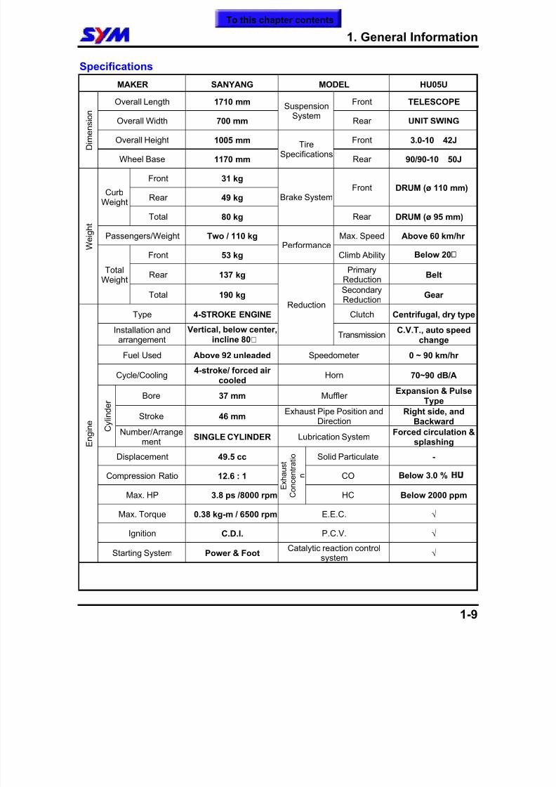
MAKER SANYANG MODEL HU05U
Overall Length 1710 mm Front TELESCOPE
Overall Width 700 mm
Suspension
System Rear UNlT SWING
Overall Height 1005 mm Front 3.0-10 42J D i m e n s i o n
Wheel Base 1170 mm
TireSpecifications
Rear 90/90-10 50J
Front 31 kg
Rear 49 kgFront DRUM (ø 110 mm)
CurbWeight
Total 80 kg
Brake System
Rear DRUM (ø 95 mm)
Passengers/Weight Two / 110 kg Max. Speed Above 60 km/hr
Front 53 kgPerformance
Climb Ability Below 20¢
Rear 137 kgPrimary
ReductionBelt
W e i g h
t
TotalWeight
Total 190 kgSecondaryReduction
Gear
Type 4-STROKE ENGINE Clutch Centrifugal, dry type
Installation and
arrangement
Vertical, below center,
incline 80¢X
Reduction
TransmissionC.V.T., auto speed
changeFuel Used Above 92 unleaded Speedometer 0 ~ 90 km/hr
Cycle/Cooling4-stroke/ forced air
cooledHorn 70~90 dB/A
Bore 37 mm MufflerExpansion & Pulse
Type
Stroke 46 mmExhaust Pipe Position and
Direction Right side, and
Backward C y l i n d e r
Number/Arrangement
SINGLE CYLINDER Lubrication SystemForced circulation &
splashing
Displacement 49.5 cc Solid Particulate -
Compression Ratio 12.6 : 1 CO Below 3.0 % ¥¤
Max. HP 3.8 ps /8000 rpm E x h a u s t
C o n c e n t r a t i o
n
HC Below 2000 ppm
Max. Torque 0.38 kg-m / 6500 rpm E.E.C. √
Ignition C.D.I. P.C.V. √
E n g i n e
Starting System Power & FootCatalytic reaction control
system √
To this chapter contents
8/12/2019 SYM Mio50 Service Manual 000
http://slidepdf.com/reader/full/sym-mio50-service-manual-000 15/215
1. General Information
1-10
Specifications
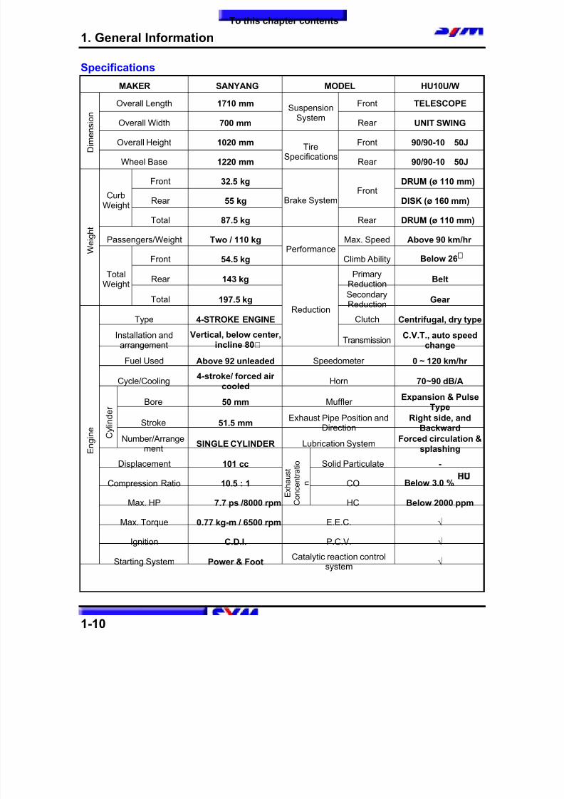
MAKER SANYANG MODEL HU10U/W
Overall Length 1710 mm Front TELESCOPE
Overall Width 700 mm
Suspension
System Rear UNlT SWING
Overall Height 1020 mm Front 90/90-10 50J D i m e n s i o n
Wheel Base 1220 mm
TireSpecifications
Rear 90/90-10 50J
Front 32.5 kg DRUM (ø 110 mm)
Rear 55 kg
Front
DISK (ø 160 mm)Curb
Weight
Total 87.5 kg
Brake System
Rear DRUM (ø 110 mm)
Passengers/Weight Two / 110 kg Max. Speed Above 90 km/hr
Front 54.5 kg
PerformanceClimb Ability Below 26¢
Rear 143 kgPrimary
ReductionBelt
W e i g h
t
TotalWeight
Total 197.5 kgSecondaryReduction
Gear
Type 4-STROKE ENGINE Clutch Centrifugal, dry type
Installation and
arrangement
Vertical, below center,
incline 80¢X
Reduction
TransmissionC.V.T., auto speed
changeFuel Used Above 92 unleaded Speedometer 0 ~ 120 km/hr
Cycle/Cooling4-stroke/ forced air
cooledHorn 70~90 dB/A
Bore 50 mm MufflerExpansion & Pulse
Type
Stroke 51.5 mmExhaust Pipe Position and
Direction Right side, and
Backward C y l i n d e r
Number/Arrangement
SINGLE CYLINDER Lubrication SystemForced circulation &
splashing
Displacement 101 cc Solid Particulate -
Compression Ratio 10.5 : 1 CO Below 3.0 % ¥¤
Max. HP 7.7 ps /8000 rpm E x h a u s t
C o n c e n t r a t i o
n
HC Below 2000 ppm
Max. Torque 0.77 kg-m / 6500 rpm E.E.C. √
Ignition C.D.I. P.C.V. √
E n g i n e
Starting System Power & FootCatalytic reaction control
system √
To this chapter contents
8/12/2019 SYM Mio50 Service Manual 000
http://slidepdf.com/reader/full/sym-mio50-service-manual-000 16/215
1. General Information
1-11
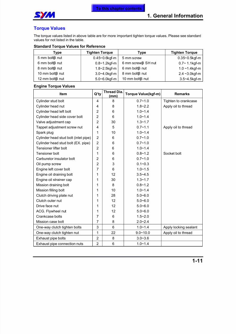
Torque Values
The torque values listed in above table are for more important tighten torque values. Please see standardvalues for not listed in the table.
Standard Torque Values for Reference
Type Tighten Torque Type Tighten Torque
5 mm bolt¡B nut 0.45~0.6kgf-m 5 mm screw 0.35~0.5kgf-m
6 mm bolt¡B nut 0.8~1.2kgf-m 6 mm screw¡B SH nut 0.7~ 1.1kgf-m
8 mm bolt¡B nut 1.8~2.5kgf-m 6 mm bolt¡B nut 1.0 ~1.4kgf-m
10 mm bolt¡B nut 3.0~4.0kgf-m 8 mm bolt¡B nut 2.4 ~3.0kgf-m
12 mm bolt¡B nut 5.0~6.0kgf-m 10 mm bolt¡B nut 3.5~4.5kgf-m Engine Torque Values
Item Q’ty Thread Dia.
(mm)
Torque Value(kgf-m) Remarks
Cylinder stud bolt 4 8 0.7~1.0 Tighten to crankcase
Cylinder head nut 4 8 1.8~2.2 Apply oil to thread
Cylinder head left bolt 2 6 1.0~1.4
Cylinder head side cover bolt 2 6 1.0~1.4
Valve adjustment cap 2 30 1.3~1.7
Tappet adjustment screw nut 4 5 0.7~1.1 Apply oil to thread
Spark plug 1 10 1.0~1.4
Cylinder head stud bolt (inlet pipe) 2 6 0.7~1.0
Cylinder head stud bolt (EX. pipe) 2 6 0.7~1.0
Tensioner lifter bolt 2 6 1.0~1.4
Tensioner bolt 1 6 0.8~1.2 Socket bolt
Carburetor insulator bolt 2 6 0.7~1.0
Oil pump screw 2 3 0.1~0.3
Engine left cover bolt 7 6 1.0~1.5
Engine oil draining bolt 1 12 3.5~4.5
Engine oil strainer cap 1 30 1.3~1.7
Mission draining bolt 1 8 0.8~1.2
Mission filling bolt 1 10 1.0~1.4
Clutch driving plate nut 1 28 5.0~6.0
Clutch outer nut 1 12 5.0~6.0
Drive face nut 1 12 5.0~6.0
ACG. Flywheel nut 1 12 5.0~6.0
Crankcase bolts 7 6 1.5~2.0
Mission case bolt 7 8 2.0~2.4
One-way clutch tighten bolts 3 6 1.0~1.4 Apply locking sealant
One-way clutch tighten nut 1 22 9.0~10.0 Apply oil to thread
Exhaust pipe bolts 2 8 3.0~3.6
Exhaust pipe connection nuts 2 6 1.0~1.4
To this chapter contents
8/12/2019 SYM Mio50 Service Manual 000
http://slidepdf.com/reader/full/sym-mio50-service-manual-000 17/215
1. General Information
1-12
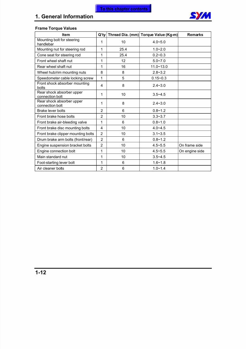
Frame Torque Values
Item Q’ty Thread Dia. (mm) Torque Value (Kg-m) Remarks
Mounting bolt for steeringhandlebar
1 10 4.0~5.0
Mounting nut for steering rod 1 25.4 1.0~2.0Cone seat for steering rod 1 25.4 0.2~0.3
Front wheel shaft nut 1 12 5.0~7.0
Rear wheel shaft nut 1 16 11.0~13.0
Wheel hub/rim mounting nuts 8 8 2.8~3.2
Speedometer cable locking screw 1 5 0.15~0.3
Front shock absorber mountingbolts
4 8 2.4~3.0
Rear shock absorber upperconnection bolt
1 10 3.5~4.5
Rear shock absorber upperconnection bolt
1 8 2.4~3.0
Brake lever bolts 2 6 0.8~1.2
Front brake hose bolts 2 10 3.3~3.7
Front brake air-bleeding valve 1 6 0.8~1.0
Front brake disc mounting bolts 4 10 4.0~4.5
Front brake clipper mounting bolts 2 10 3.1~3.5
Drum brake arm bolts (front/rear) 2 6 0.8~1.2
Engine suspension bracket bolts 2 10 4.5~5.5 On frame side
Engine connection bolt 1 10 4.5~5.5 On engine sideMain standard nut 1 10 3.5~4.5
Foot-starting lever bolt 1 6 1.6~1.8
Air cleaner bolts 2 6 1.0~1.4
To this chapter contents
8/12/2019 SYM Mio50 Service Manual 000
http://slidepdf.com/reader/full/sym-mio50-service-manual-000 18/215
1. General Information
1-13
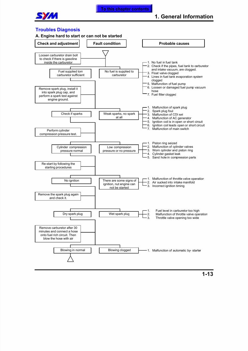
Troubles Diagnosis
A. Engine hard to start or can not be started
To this chapter contents
Check and adjustment Fault condition Probable causes
Loosen carburetor drain boltto check if there is gasoline
inside the carburetor
Fuel supplied tomcarburetor sufficient
No fuel is supplied tocarburetor
Remove spark plug, install itinto spark plug cap, and
perform a spark test againstengine ground.
Perform cylindercompression pressure test.
Check if sparks Weak sparks, no sparkat all
Cylinder compressionpressure normal
Low compressionpressure or no pressure
Re-start by following thestarting procedures
No ignition There are some signs ofignition, nut engine can
not be started
Remove the spark plug againand check it.
Remove carburetor after 30minutes and connect a hoseonto fuel rich circuit. Then
blow the hose with air
Dry spark plug Wet spark plug
Blowing in normal Blowing clogged
1. No fuel in fuel tank2. Check if the pipes, fuel tank to carburetor
and intake vacuum, are clogged.3. Float valve clogged4. Lines in fuel tank evaporation system
clogged5. Malfunction of fuel pump6. Loosen or damaged fuel pump vacuum
hose7. Fuel filter clogged
1. Malfunction of spark plug2. Spark plug foul3. Malfunction of CDI set4. Malfunction of AC generator5. Ignition coil is in open or short circuit6. Ignition coil leads open or short circuit7. Malfunction of main switch
1. Piston ring seized2. Malfunction of cylinder valves3. Worn cylinder and piston ring
4. Cylinder gasket leak5. Sand hole in compression parts
1. Malfunction of throttle valve operation2. Air sucked into intake manifold3. Incorrect ignition timing
1. Fuel level in carburetor too high2. Malfunction of throttle valve operation3. Throttle valve opening too wide
1. Malfunction of automatic by- starter
8/12/2019 SYM Mio50 Service Manual 000
http://slidepdf.com/reader/full/sym-mio50-service-manual-000 19/215
1. General Information
1-14
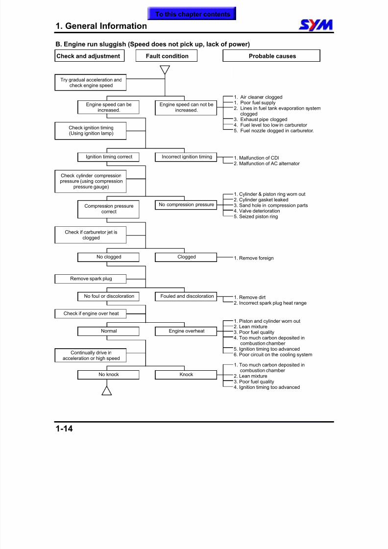
B. Engine run sluggish (Speed does not pick up, lack of power)
Check and adjustment Fault condition Probable causes
Try gradual acceleration andcheck engine speed
Engine speed can beincreased.
Engine speed can not beincreased.
Check ignition timing(Using ignition lamp)
Check cylinder compressionpressure (using compression
pressure gauge)
Ignition timing correct Incorrect ignition timing
Compression pressurecorrect
No compression pressure
Check if carburetor jet is
clogged
No clogged Clogged
Remove spark plug
Check if engine over heat
No foul or discoloration Fouled and discoloration
No knock Knock
1. Air cleaner clogged1. Poor fuel supply2. Lines in fuel tank evaporation system
clogged3. Exhaust pipe clogged4. Fuel level too low in carburetor5. Fuel nozzle clogged in carburetor.
1. Malfunction of CDI2. Malfunction of AC alternator
1. Cylinder & piston ring worn out2. Cylinder gasket leaked3. Sand hole in compression parts4. Valve deterioration5. Seized piston ring
1. Remove foreign
1. Remove dirt2. Incorrect spark plug heat range
1. Piston and cylinder worn out2. Lean mixture3. Poor fuel quality4. Too much carbon deposited in
combustion chamber5. Ignition timing too advanced6. Poor circuit on the cooling system
Normal Engine overheat
Continually drive inacceleration or high speed
1. Too much carbon deposited incombustion chamber
2. Lean mixture3. Poor fuel quality4. Ignition timing too advanced
To this chapter contents
8/12/2019 SYM Mio50 Service Manual 000
http://slidepdf.com/reader/full/sym-mio50-service-manual-000 20/215
1. General Information
1-15
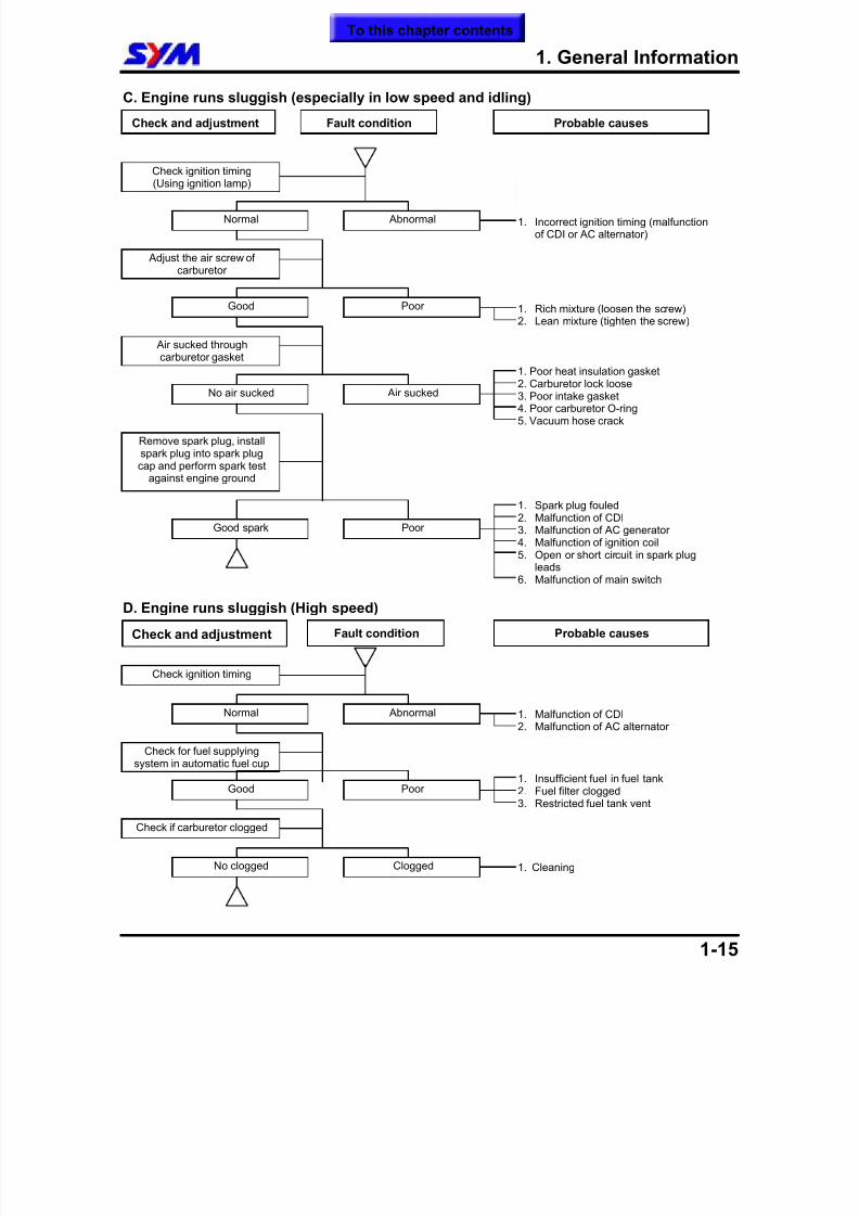
C. Engine runs sluggish (especially in low speed and idling)
D. Engine runs sluggish (High speed)
Check and adjustment Fault condition Probable causes
Check ignition timing(Using ignition lamp)
Check for fuel supplyingsystem in automatic fuel cup
Check if carburetor clogged
1. Incorrect ignition timing (malfunctionof CDI or AC alternator)
1. Rich mixture (loosen the screw)2. Lean mixture (tighten the screw)
1. Poor heat insulation gasket2. Carburetor lock loose3. Poor intake gasket4. Poor carburetor O-ring5. Vacuum hose crack
1. Spark plug fouled2. Malfunction of CDI
3. Malfunction of AC generator4. Malfunction of ignition coil5. Open or short circuit in spark plug
leads6. Malfunction of main switch
1. Insufficient fuel in fuel tank2. Fuel filter clogged3. Restricted fuel tank vent
Good Poor
Good spark Poor
No air sucked Air sucked
Good Poor
Normal Abnormal
Air sucked through
carburetor gasket
Adjust the air screw ofcarburetor
Remove spark plug, installspark plug into spark plugcap and perform spark test
against engine ground
Check and adjustment Fault condition Probable causes
Check ignition timing
1. Malfunction of CDI2. Malfunction of AC alternator
Normal Abnormal
No clogged Clogged 1. Cleaning
To this chapter contents
8/12/2019 SYM Mio50 Service Manual 000
http://slidepdf.com/reader/full/sym-mio50-service-manual-000 21/215
1. General Information
1-16
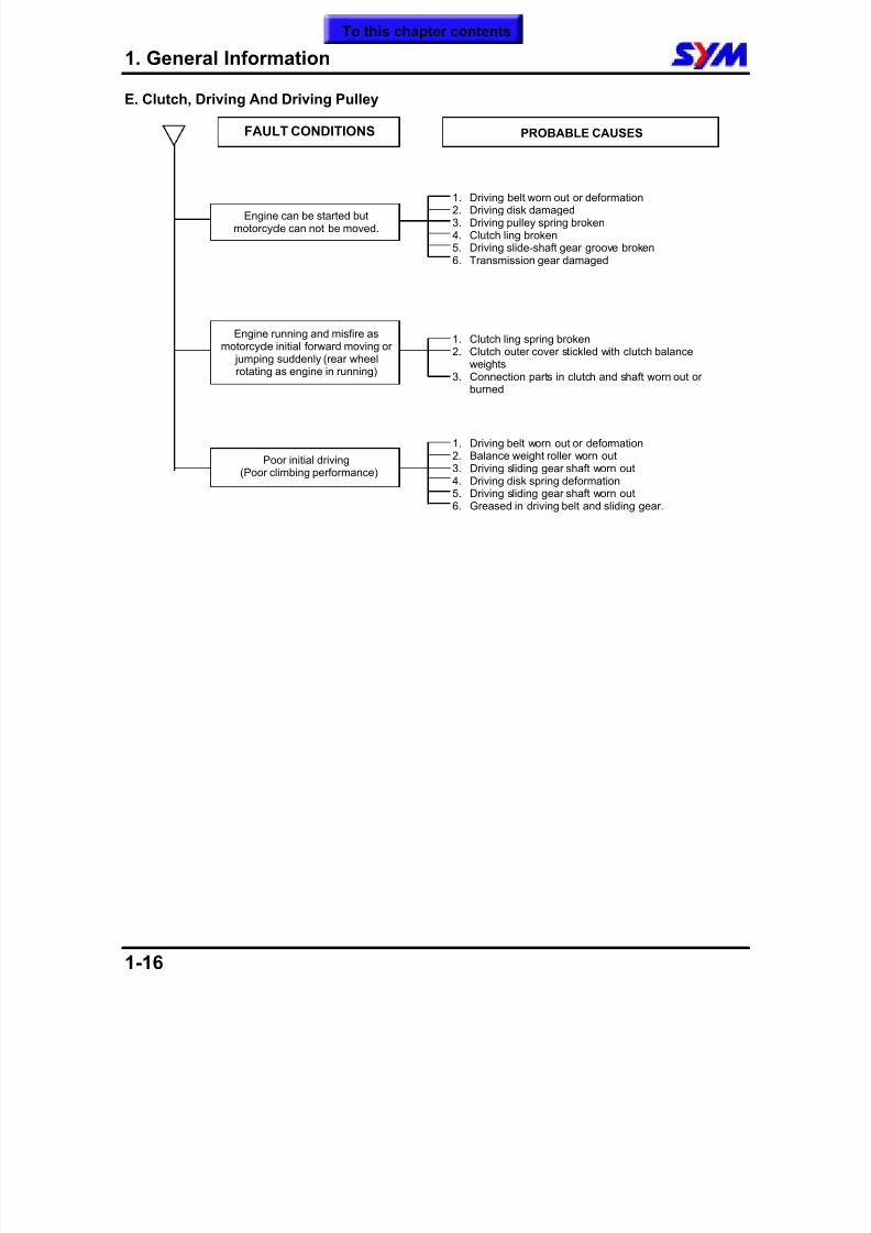
E. Clutch, Driving And Driving Pulley
1. Clutch ling spring broken2. Clutch outer cover stickled with clutch balance
weights3. Connection parts in clutch and shaft worn out or
burned
Engine can be started butmotorcycle can not be moved.
FAULT CONDITIONS PROBABLE CAUSES
1. Driving belt worn out or deformation2. Driving disk damaged3. Driving pulley spring broken4. Clutch ling broken5. Driving slide-shaft gear groove broken6. Transmission gear damaged
Engine running and misfire asmotorcycle initial forward moving or
jumping suddenly (rear wheelrotating as engine in running)
Poor initial driving(Poor climbing performance)
1. Driving belt worn out or deformation2. Balance weight roller worn out3. Driving sliding gear shaft worn out4. Driving disk spring deformation5. Driving sliding gear shaft worn out6. Greased in driving belt and sliding gear.
To this chapter contents
8/12/2019 SYM Mio50 Service Manual 000
http://slidepdf.com/reader/full/sym-mio50-service-manual-000 22/215
1. General Information
1-17
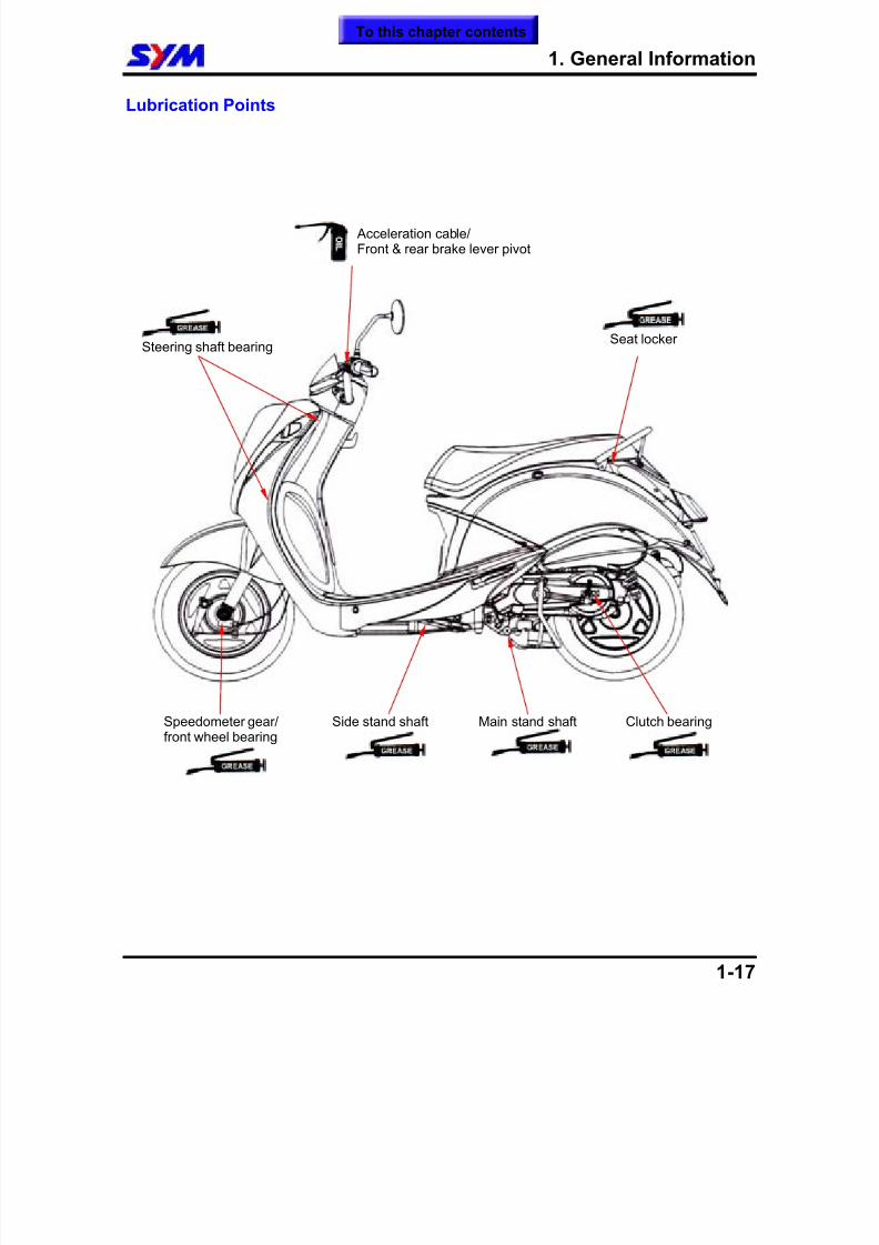
Lubrication Points
Steering shaft bearingSeat locker
Clutch bearing
Main stand shaft
Side stand shaftSpeedometer gear/front wheel bearing
Acceleration cable/Front & rear brake lever pivot
To this chapter contents

8/12/2019 SYM Mio50 Service Manual 000
http://slidepdf.com/reader/full/sym-mio50-service-manual-000 23/215
1. General Information
1-18
Note:
To this chapter contents
8/12/2019 SYM Mio50 Service Manual 000
http://slidepdf.com/reader/full/sym-mio50-service-manual-000 24/215
2. Maintenance Information
2-1
Precautions in Operation...................... 2-1
Periodical Maintenance Schedule........ 2-2
Lubrication System............................... 2-3
Fuel System ........................................... 2-4
Air Cleaner ............................................. 2-5
Throttle Valve Operation....................... 2-5
Crankcase Blow-By Ventilation............ 2-6
Valve Clearance Adjustment ................ 2-6
Carburetor Idle Speed Adjustment ...... 2-7
Ignition System...................................... 2-8
Spark Plug.............................................. 2-8
Cylinder Compression Pressure..... 2-9
Driving System................................. 2-9
Steering System............................... 2-10
Suspension System ......................... 2-10
Front Disk Brake System................. 2-11
Drum Brake System ......................... 2-13
Wheel / Tire....................................... 2-14
Battery............................................... 2-15
Headlight Adjustment ...................... 2-15
Nuts¡ Bolts Tightness..................... 2-15
Special Service Tools Catalogue.... 2-16
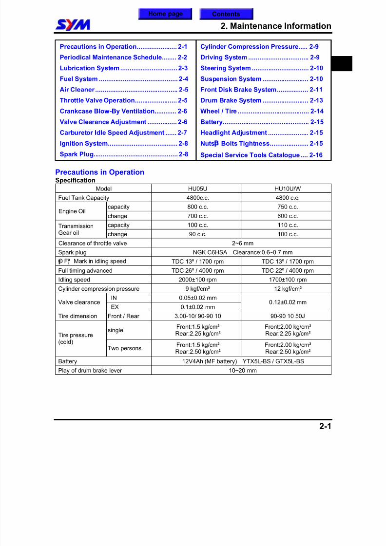
Precautions in OperationSpecification
Model HU05U HU10U/W
Fuel Tank Capacity 4800c.c. 4800 c.c.
capacity 800 c.c. 750 c.c.Engine Oil
change 700 c.c. 600 c.c.
capacity 100 c.c. 110 c.c.TransmissionGear oil change 90 c.c. 100 c.c.
Clearance of throttle valve 2~6 mm
Spark plug NGK C6HSA Clearance:0.6~0.7 mm ¡ © F¡ª Mark in idling speed TDC 13º / 1700 rpm TDC 13º / 1700 rpm
Full timing advanced TDC 26º / 4000 rpm TDC 22º / 4000 rpm
Idling speed 2000±100 rpm 1700±100 rpm
Cylinder compression pressure 9 kgf/cm² 12 kgf/cm² IN 0.05±0.02 mm
Valve clearanceEX 0.1±0.02 mm
0.12±0.02 mm
Tire dimension Front / Rear 3.00-10/ 90-90 10 90-90 10 50J
single Front:1.5 kg/cm²Rear:2.25 kg/cm²
Front:2.00 kg/cm²Rear:2.25 kg/cm² Tire pressure
(cold) Two persons Front:1.5 kg/cm²
Rear:2.50 kg/cm² Front:2.00 kg/cm²Rear:2.50 kg/cm²
Battery 12V4Ah (MF battery) YTX5L-BS / GTX5L-BS
Play of drum brake lever 10~20 mm
2
Home page Contents
8/12/2019 SYM Mio50 Service Manual 000
http://slidepdf.com/reader/full/sym-mio50-service-manual-000 25/215
2. Maintenance Information
2-2
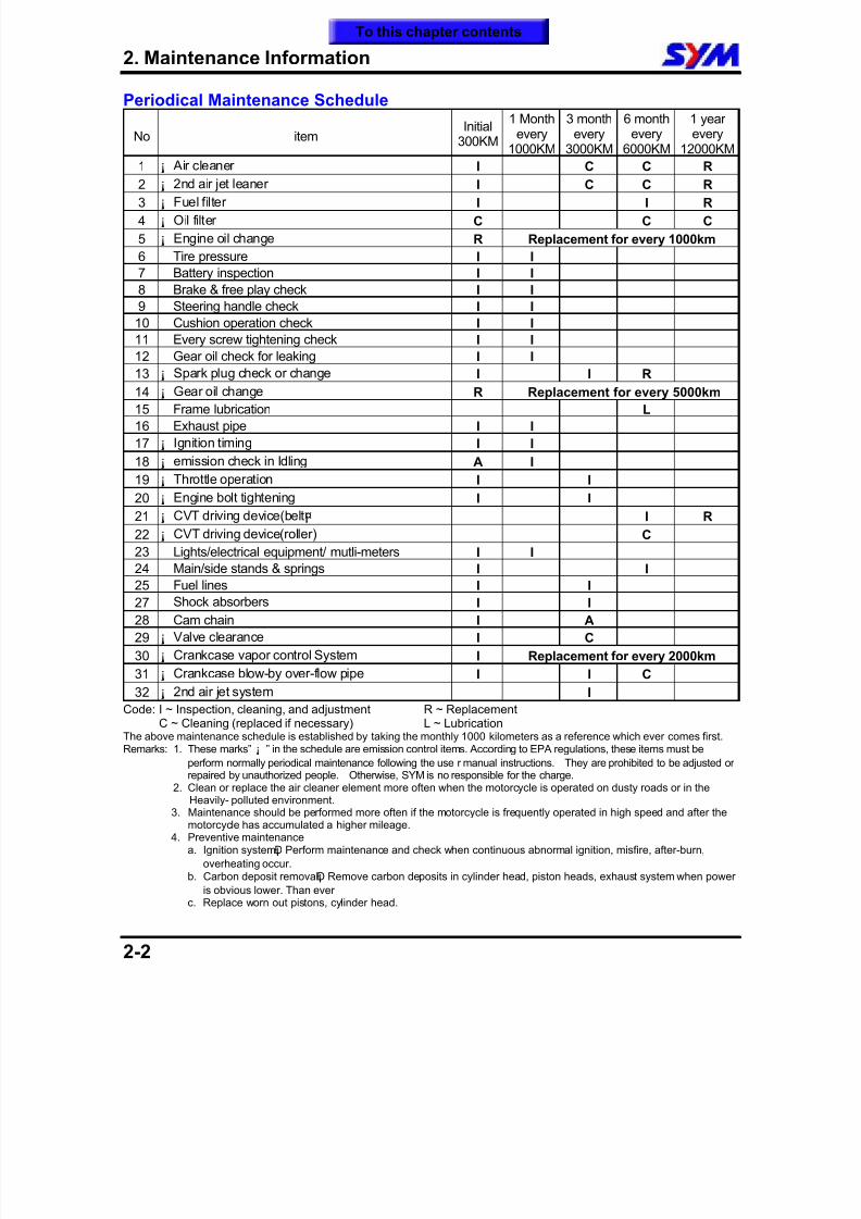
Periodical Maintenance Schedule
No itemInitial
300KM
1 Monthevery
1000KM
3 monthevery
3000KM
6 monthevery
6000KM
1 yearevery
12000KM
1 ¡ Air cleaner I C C R
2 ¡ 2nd air jet leaner I C C R
3 ¡ Fuel filter I I R
4 ¡ Oil filter C C C
5 ¡ Engine oil change R Replacement for every 1000km
6 Tire pressure I I
7 Battery inspection I I
8 Brake & free play check I I
9 Steering handle check I I
10 Cushion operation check I I
11 Every screw tightening check I I
12 Gear oil check for leaking I I13 ¡ Spark plug check or change I I R
14 ¡ Gear oil change R Replacement for every 5000km
15 Frame lubrication L
16 Exhaust pipe I I
17 ¡ Ignition timing I I
18 ¡ emission check in Idling A I
19 ¡ Throttle operation I I
20 ¡ Engine bolt tightening I I
21 ¡ CVT driving device(belt¡¤ I R
22 ¡ CVT driving device(roller) C23 Lights/electrical equipment/ mutli-meters I I
24 Main/side stands & springs I I
25 Fuel lines I I
27 Shock absorbers I I
28 Cam chain I A
29 ¡ Valve clearance I C
30 ¡ Crankcase vapor control System I Replacement for every 2000km
31 ¡ Crankcase blow-by over-flow pipe I I C
32 ¡ 2nd air jet system I
Code: I ~ Inspection, cleaning, and adjustment R ~ ReplacementC ~ Cleaning (replaced if necessary) L ~ Lubrication
The above maintenance schedule is established by taking the monthly 1000 kilometers as a reference which ever comes first.Remarks: 1. These marks” ¡ ” in the schedule are emission control items. According to EPA regulations, these items must be
perform normally periodical maintenance following the use r manual instructions. They are prohibited to be adjusted orrepaired by unauthorized people. Otherwise, SYM is no responsible for the charge.
2. Clean or replace the air cleaner element more often when the motorcycle is operated on dusty roads or in theHeavily- polluted environment.
3. Maintenance should be performed more often if the motorcycle is frequently operated in high speed and after themotorcycle has accumulated a higher mileage.
4. Preventive maintenancea. Ignition system¡ Ð Perform maintenance and check when continuous abnormal ignition, misfire, after-burn,
overheating occur.b. Carbon deposit removal¡ Ð Remove carbon deposits in cylinder head, piston heads, exhaust system when power
is obvious lower. Than everc. Replace worn out pistons, cylinder head.
To this chapter contents
8/12/2019 SYM Mio50 Service Manual 000
http://slidepdf.com/reader/full/sym-mio50-service-manual-000 26/215
8/12/2019 SYM Mio50 Service Manual 000
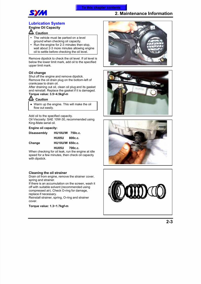
http://slidepdf.com/reader/full/sym-mio50-service-manual-000 27/215
2. Maintenance Information
2-4
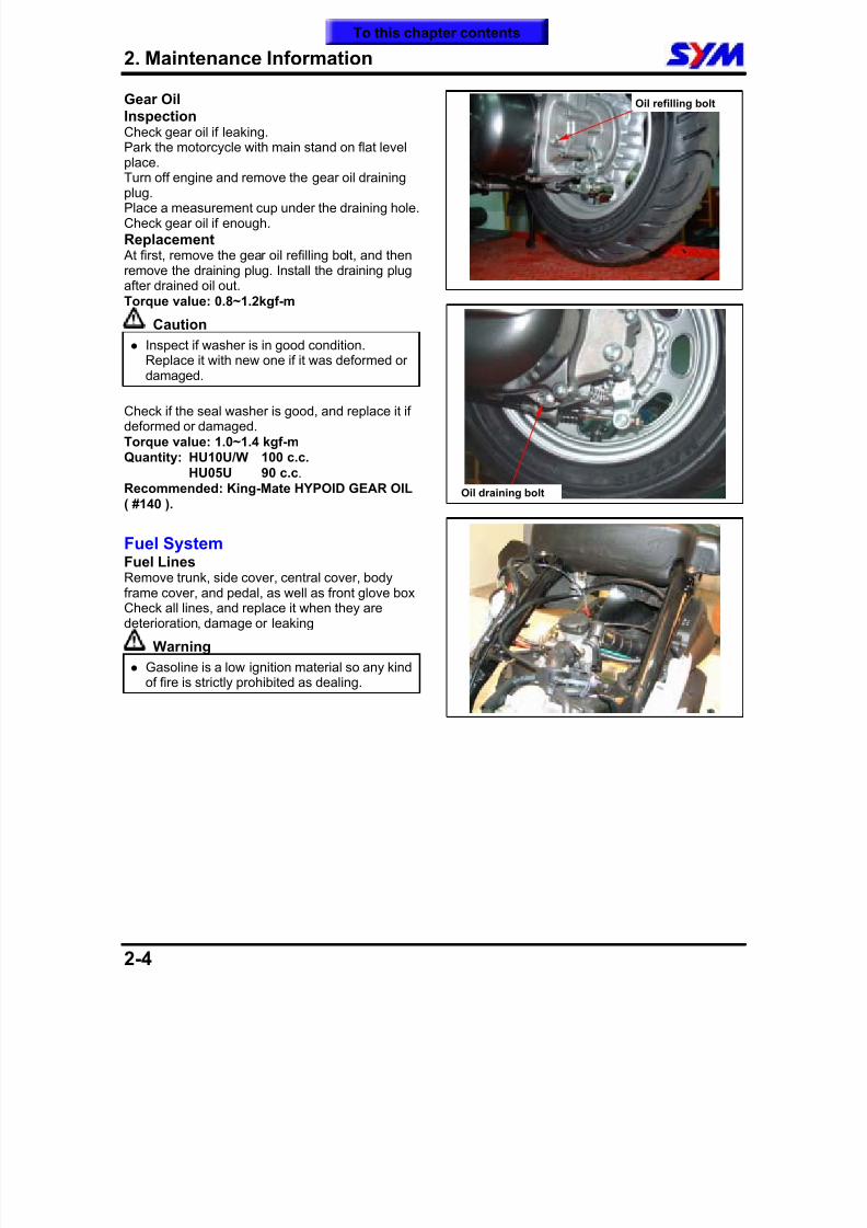
Gear OilInspectionCheck gear oil if leaking.Park the motorcycle with main stand on flat levelplace.
Turn off engine and remove the gear oil drainingplug.Place a measurement cup under the draining hole.Check gear oil if enough.
Replacement At first, remove the gear oil refilling bolt, and thenremove the draining plug. Install the draining plugafter drained oil out.Torque value: 0.8~1.2kgf-m
Caution
Inspect if washer is in good condition.
Replace it with new one if it was deformed ordamaged.
Check if the seal washer is good, and replace it ifdeformed or damaged.Torque value: 1.0~1.4 kgf-m
Quantity: HU10U/W 100 c.c.HU05U 90 c.c.
Recommended: King-Mate HYPOID GEAR OIL( #140 ).
Fuel SystemFuel LinesRemove trunk, side cover, central cover, bodyframe cover, and pedal, as well as front glove boxCheck all lines, and replace it when they aredeterioration, damage or leaking
Warning
Gasoline is a low ignition material so any kindof fire is strictly prohibited as dealing.
Oil draining bolt
Oil refilling bolt
To this chapter contents
8/12/2019 SYM Mio50 Service Manual 000
http://slidepdf.com/reader/full/sym-mio50-service-manual-000 28/215
2. Maintenance Information
2-5
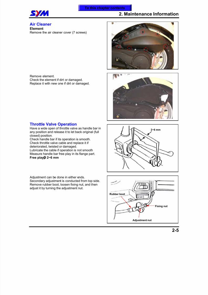
Air CleanerElementRemove the air cleaner cover (7 screws)
Remove element.Check the element if dirt or damaged.Replace it with new one if dirt or damaged.
Throttle Valve Operation
Have a wide open of throttle valve as handle bar inany position and release it to let back original (fullclosed) position.Check handle bar if its operation is smooth.Check throttle valve cable and replace it ifdeteriorated, twisted or damaged.Lubricate the cable if operation is not smoothMeasure handle bar free play in its flange part.Free play¡G 2~6 mm
Adjustment can be done in either ends.Secondary adjustment is conducted from top side.Remove rubber boot, loosen fixing nut, and thenadjust it by turning the adjustment nut.
2~6 mm
Rubber boot
Fixing nut
Adjustment nut
To this chapter contents
8/12/2019 SYM Mio50 Service Manual 000
http://slidepdf.com/reader/full/sym-mio50-service-manual-000 29/215
2. Maintenance Information
2-6
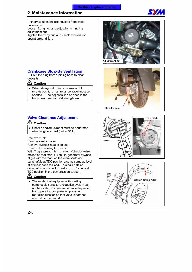
Primary adjustment is conducted from cablebutton side.Loosen fixing nut, and adjust by turning theadjustment nut.Tighten the fixing nut, and check acceleration
operation condition.
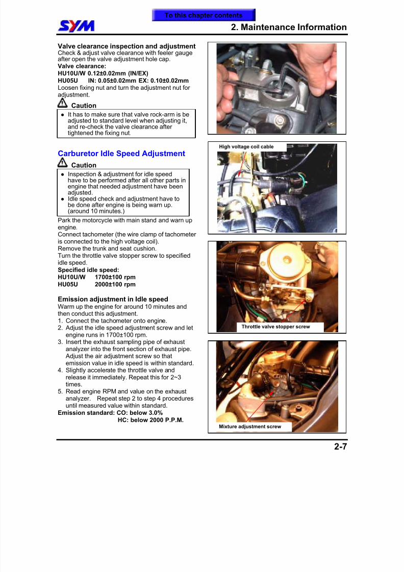
Crankcase Blow-By VentilationPull out the plug from draining hose to clean
depositsCaution
When always riding in rainy area or fullthrottle position, maintenance travel must beshorted. The deposits can be seen in thetransparent section of draining hose.
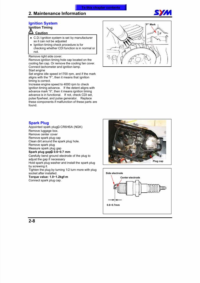
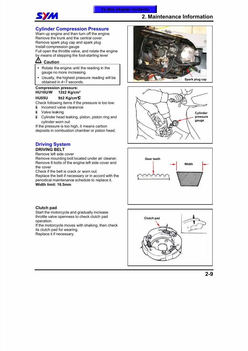
Valve Clearance AdjustmentCaution
Checks and adjustment must be performedwhen engine is cold (below 35¢J ).
Remove trunkRemove central coverRemove cylinder head side-cap.Remove the cooling fan cover.With T type wrench, turn crankshaft in clockwisemotion so that mark (T) on the generator flywheel
aligns with the mark on the crankshaft, andcamshaft is at TDC position also as same as levelof cylinder head top-end. A single hole oncamshaft sprocket is forward to up. (Piston is atTDC position in the compression stroke.)
Caution
The model that equipped with startingcompression pressure reduction system cannot be rotated in counter-clockwise to preventfrom operating compression pressurereduction function so that valve clearance
can not be measured.
Ignition timing mark
TDC mark
Adjustment nut
Blow-by hose
To this chapter contents
8/12/2019 SYM Mio50 Service Manual 000
http://slidepdf.com/reader/full/sym-mio50-service-manual-000 30/215
2. Maintenance Information
2-7
Valve clearance inspection and adjustmentCheck & adjust valve clearance with feeler gaugeafter open the valve adjustment hole cap.Valve clearance:HU10U/W 0.12±0.02mm (IN/EX)
HU05U IN: 0.05±0.02mm EX: 0.10±0.02mmLoosen fixing nut and turn the adjustment nut foradjustment.
Caution
It has to make sure that valve rock-arm is beadjusted to standard level when adjusting it,and re-check the valve clearance aftertightened the fixing nut.
Carburetor Idle Speed Adjustment
Caution Inspection & adjustment for idle speed
have to be performed after all other parts inengine that needed adjustment have beenadjusted.
Idle speed check and adjustment have tobe done after engine is being warn up.(around 10 minutes.)
Park the motorcycle with main stand and warn upengine.Connect tachometer (the wire clamp of tachometeris connected to the high voltage coil).
Remove the trunk and seat cushion.Turn the throttle valve stopper screw to specifiedidle speed.Specified idle speed:HU10U/W 1700±100 rpmHU05U 2000±100 rpm
Emission adjustment in Idle speedWarm up the engine for around 10 minutes andthen conduct this adjustment.1. Connect the tachometer onto engine.2. Adjust the idle speed adjustment screw and let
engine runs in 1700±100 rpm.3. Insert the exhaust sampling pipe of exhaust
analyzer into the front section of exhaust pipe. Adjust the air adjustment screw so thatemission value in idle speed is within standard.
4. Slightly accelerate the throttle valve andrelease it immediately. Repeat this for 2~3times.
5. Read engine RPM and value on the exhaustanalyzer. Repeat step 2 to step 4 proceduresuntil measured value within standard.
Emission standard: CO: below 3.0%HC: below 2000 P.P.M.
Throttle valve stopper screw
High voltage coil cable
Mixture adjustment screw
To this chapter contents
8/12/2019 SYM Mio50 Service Manual 000
http://slidepdf.com/reader/full/sym-mio50-service-manual-000 31/215
2. Maintenance Information
2-8
Ignition SystemIgnition Timing
Caution
C.D.I ignition system is set by manufacturer
so it can not be adjusted Ignition timing check procedure is for
checking whether CDI function is in normal ornot.
Remove right side cover.Remove ignition timing hole cap located on thecooling fan cap. Or remove the cooling fan cover.Connect tachometer and ignition lamp.Start engineSet engine idle speed in1700 rpm, and if the markaligns with the “F”, then it means that ignition
timing is correct.Increase engine speed to 4000 rpm to checkignition timing advance. If the detent aligns withadvance mark “II”, then it means ignition timingadvance is in functional. If not, check CDI set,pulse flywheel, and pulse generator. Replacethese components if malfunction of these parts arefound.
Spark Plug Appointed spark plug¡G CR6HSA (NGK)
Remove luggage box.Remove center coverRemove spark plug capClean dirt around the spark plug hole.Remove spark plugMeasure spark plug gapSpark plug gap
¡G
0.6~0.7 mm
Carefully bend ground electrode of the plug toadjust the gap if necessaryHold spark plug washer and install the spark plugby screwing it.Tighten the plug by turning 1/2 turn more with plugsocket after installed.Torque value: 1.0~1.2kgf-mConnect spark plug cap.
“F” Mark
0.6~0.7mm
Side electrode
Center electrode
Plug cap
To this chapter contents
8/12/2019 SYM Mio50 Service Manual 000
http://slidepdf.com/reader/full/sym-mio50-service-manual-000 32/215
2. Maintenance Information
2-9
Cylinder Compression PressureWarn up engine and then turn off the engine.Remove the trunk and the central cover.Remove spark plug cap and spark plugInstall compression gauge
Full open the throttle valve, and rotate the engineby means of stepping the foot-starting lever
Caution
Rotate the engine until the reading in thegauge no more increasing.
Usually, the highest pressure reading will beobtained in 4~7 seconds.
Compression pressure:HU10U/W 12±2 Kg/cm²
HU05U 9±2 Kg/cm²¡C
Check following items if the pressure is too low:£» Incorrect valve clearance
£» Valve leaking
£» Cylinder head leaking, piston, piston ring and
cylinder worn outIf the pressure is too high, it means carbondeposits in combustion chamber or piston head.
Driving SystemDRIVING BELT
Remove left side coverRemove mounting bolt located under air cleaner.Remove 8 bolts of the engine left side cover andthe coverCheck if the belt is crack or worn out.Replace the belt if necessary or in accord with theperiodical maintenance schedule to replace it.Width limit: 16.5mm
Clutch padStart the motorcycle and gradually increasethrottle valve openness to check clutch padoperation.If the motorcycle moves with shaking, then checkits clutch pad for wearing.Replace it if necessary.
Gear teeth
Width
Cylinderpressuregauge
Clutch pad
Spark plug cap
To this chapter contents
8/12/2019 SYM Mio50 Service Manual 000
http://slidepdf.com/reader/full/sym-mio50-service-manual-000 33/215
2. Maintenance Information
2-10
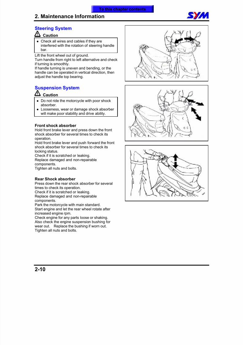
Steering System
Caution
Check all wires and cables if they areinterfered with the rotation of steering handle
bar.Lift the front wheel out of ground.Turn handle from right to left alternative and checkif turning is smoothly.If handle turning is uneven and bending, or thehandle can be operated in vertical direction, thenadjust the handle top bearing.
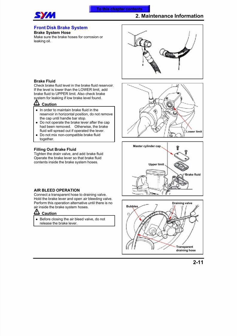
Suspension System
Caution
Do not ride the motorcycle with poor shockabsorber.
Looseness, wear or damage shock absorberwill make poor stability and drive ability.
Front shock absorberHold front brake lever and press down the frontshock absorber for several times to check itsoperation.Hold front brake lever and push forward the frontshock absorber for several times to check its
locking status.Check if it is scratched or leaking.Replace damaged and non-repairablecomponents.Tighten all nuts and bolts.
Rear Shock absorberPress down the rear shock absorber for severaltimes to check its operation.Check if it is scratched or leaking.Replace damaged and non-repairable
components.Park the motorcycle with main standard.Start engine and let the rear wheel rotate afterincreased engine rpm.Check engine for any parts loose or shaking. Also check the engine suspension bushing forwear out. Replace the bushing if worn out.Tighten all nuts and bolts.
To this chapter contents
8/12/2019 SYM Mio50 Service Manual 000
http://slidepdf.com/reader/full/sym-mio50-service-manual-000 34/215
8/12/2019 SYM Mio50 Service Manual 000
http://slidepdf.com/reader/full/sym-mio50-service-manual-000 35/215
2. Maintenance Information
2-12
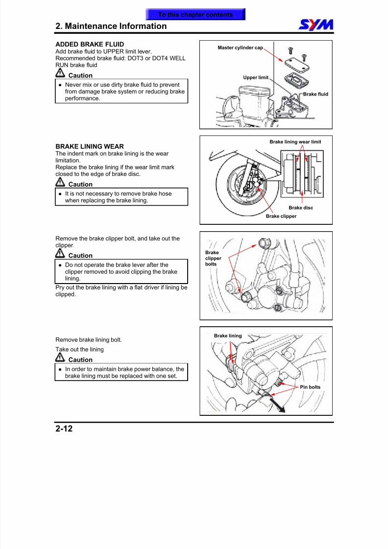
ADDED BRAKE FLUID Add brake fluid to UPPER limit lever.Recommended brake fluid: DOT3 or DOT4 WELLRUN brake fluid
Caution
Never mix or use dirty brake fluid to preventfrom damage brake system or reducing brakeperformance.
BRAKE LINING WEARThe indent mark on brake lining is the wear
limitation.Replace the brake lining if the wear limit markclosed to the edge of brake disc.
Caution
It is not necessary to remove brake hosewhen replacing the brake lining.
Remove the brake clipper bolt, and take out theclipper.
Caution
Do not operate the brake lever after theclipper removed to avoid clipping the brakelining.
Pry out the brake lining with a flat driver if lining beclipped.
Remove brake lining bolt.
Take out the lining
Caution
In order to maintain brake power balance, thebrake lining must be replaced with one set.
Brake lining wear limit
Brake clipper
Brake disc
Brakeclipperbolts
Pin bolts
Brake lining
Master cylinder cap
Upper limit
Brake fluid
To this chapter contents
8/12/2019 SYM Mio50 Service Manual 000
http://slidepdf.com/reader/full/sym-mio50-service-manual-000 36/215
2. Maintenance Information
2-13
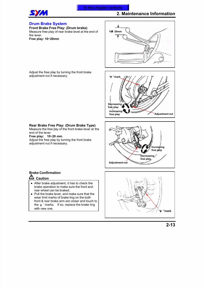
Drum Brake System
Front Brake Free Play: (Drum brake)Measure free play of rear brake level at the end ofthe lever.Free play: 10~20mm
Adjust the free play by turning the front brakeadjustment nut if necessary.
Rear Brake Free Play: (Drum Brake Type)Measure the free [lay of the front brake lever at theend of the lever.Free play: 10~20 mm Adjust the free play by turning the front brakeadjustment nut if necessary.
Brake Confirmation
Caution
After brake adjustment, it has to check thebrake operation to make sure the front andrear wheel can be braked.
Pull the brake lever, and make sure that thewear limit marks of brake ling on the bothfront & rear brake arm are closer and touch tothe ¡µ ’ marks. If so, replace the brake ling
with new one.
10¡ã 20mm
Adjustment nut
Decreasingfree play
Increasingfree play
“¡µ
”mark
“¡µ
”mark
Adjustment nut
Decreasingfree play
Increasingfree play
To this chapter contents
8/12/2019 SYM Mio50 Service Manual 000
http://slidepdf.com/reader/full/sym-mio50-service-manual-000 37/215
2. Maintenance Information
2-14
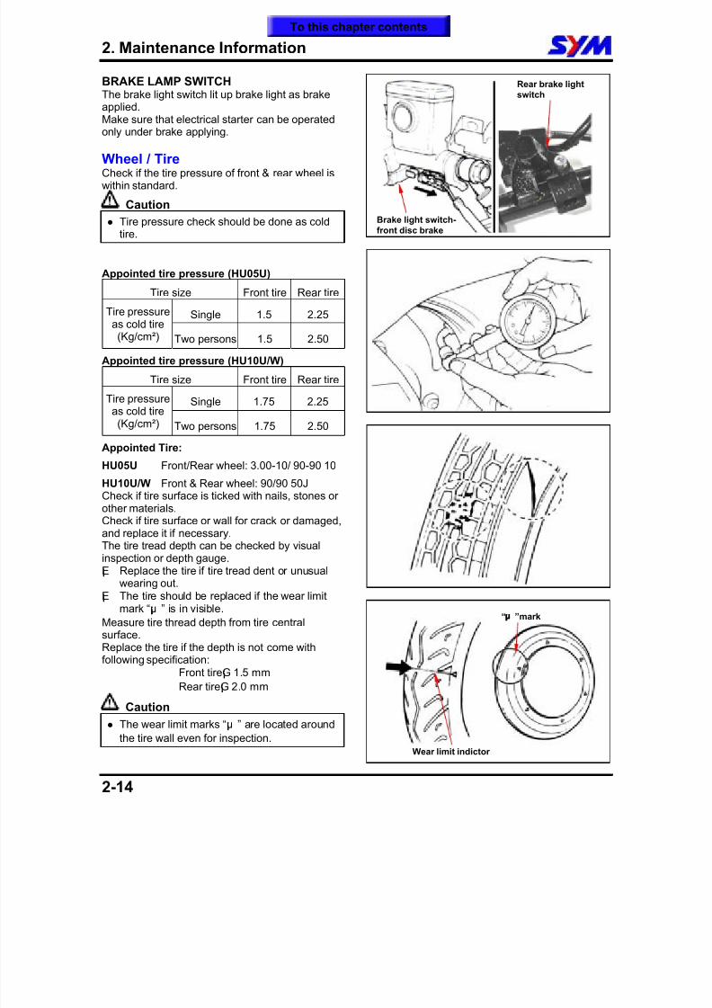
BRAKE LAMP SWITCH
The brake light switch lit up brake light as brakeapplied.Make sure that electrical starter can be operatedonly under brake applying.
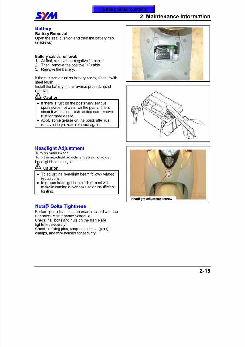
Wheel / TireCheck if the tire pressure of front & rear wheel iswithin standard.
Caution
Tire pressure check should be done as coldtire.
Appointed tire pressure (HU05U)
Tire size Front tire Rear tire
Single 1.5 2.25Tire pressureas cold tire(Kg/cm²) Two persons 1.5 2.50
Appointed tire pressure (HU10U/W)
Tire size Front tire Rear tire
Single 1.75 2.25Tire pressureas cold tire(Kg/cm²) Two persons 1.75 2.50
Appointed Tire:
HU05U Front/Rear wheel: 3.00-10/ 90-90 10
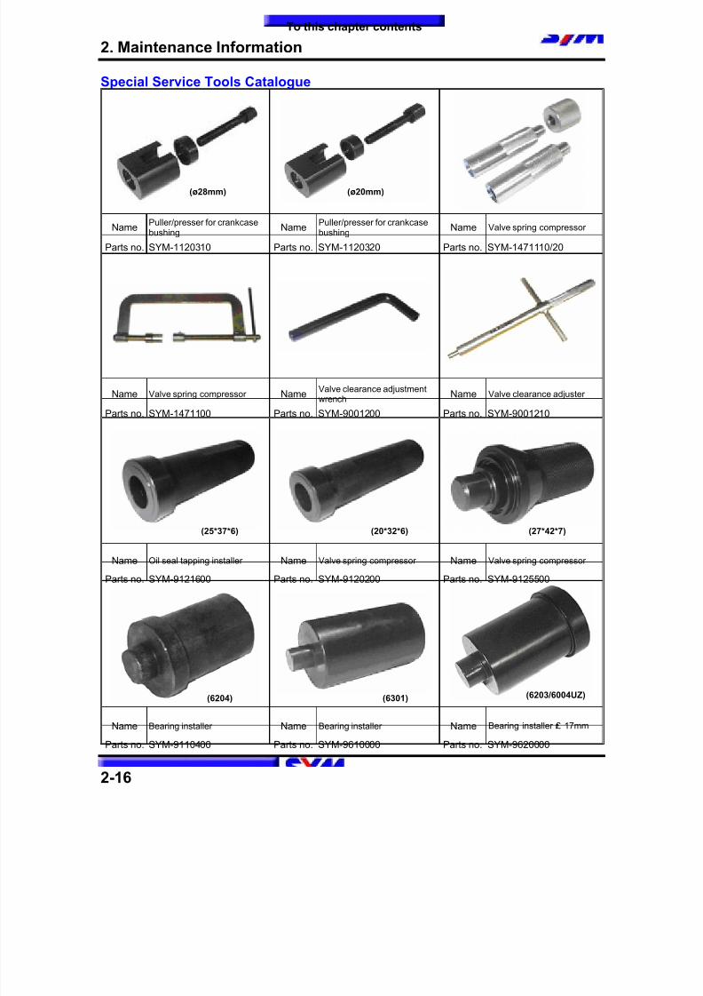
HU10U/W Front & Rear wheel: 90/90 50JCheck if tire surface is ticked with nails, stones orother materials.Check if tire surface or wall for crack or damaged,and replace it if necessary.The tire tread depth can be checked by visualinspection or depth gauge.¡E Replace the tire if tire tread dent or unusual
wearing out.¡E The tire should be replaced if the wear limitmark “¡µ ” is in visible.
Measure tire thread depth from tire centralsurface.Replace the tire if the depth is not come withfollowing specification:
Front tire¡G 1.5 mm
Rear tire¡G 2.0 mm
Caution
The wear limit marks “¡µ ” are located around
the tire wall even for inspection.
Rear brake lightswitch
“¡µ
”mark
Brake light switch-front disc brake
Wear limit indictor
To this chapter contents
8/12/2019 SYM Mio50 Service Manual 000
http://slidepdf.com/reader/full/sym-mio50-service-manual-000 38/215
2. Maintenance Information
2-15
BatteryBattery RemovalOpen the seat cushion and then the battery cap.(2 screws)
Battery cables removal:1. At first, remove the negative “-“ cable.2. Then, remove the positive “+” cable3. Remove the battery.
If there is some rust on battery posts, clean it withsteel brush.Install the battery in the reverse procedures ofremoval.
Caution
If there is rust on the posts very serious,spray some hot water on the posts. Then,clean it with steel brush so that can removerust for more easily.
Apply some grease on the posts after rustremoved to prevent from rust again.
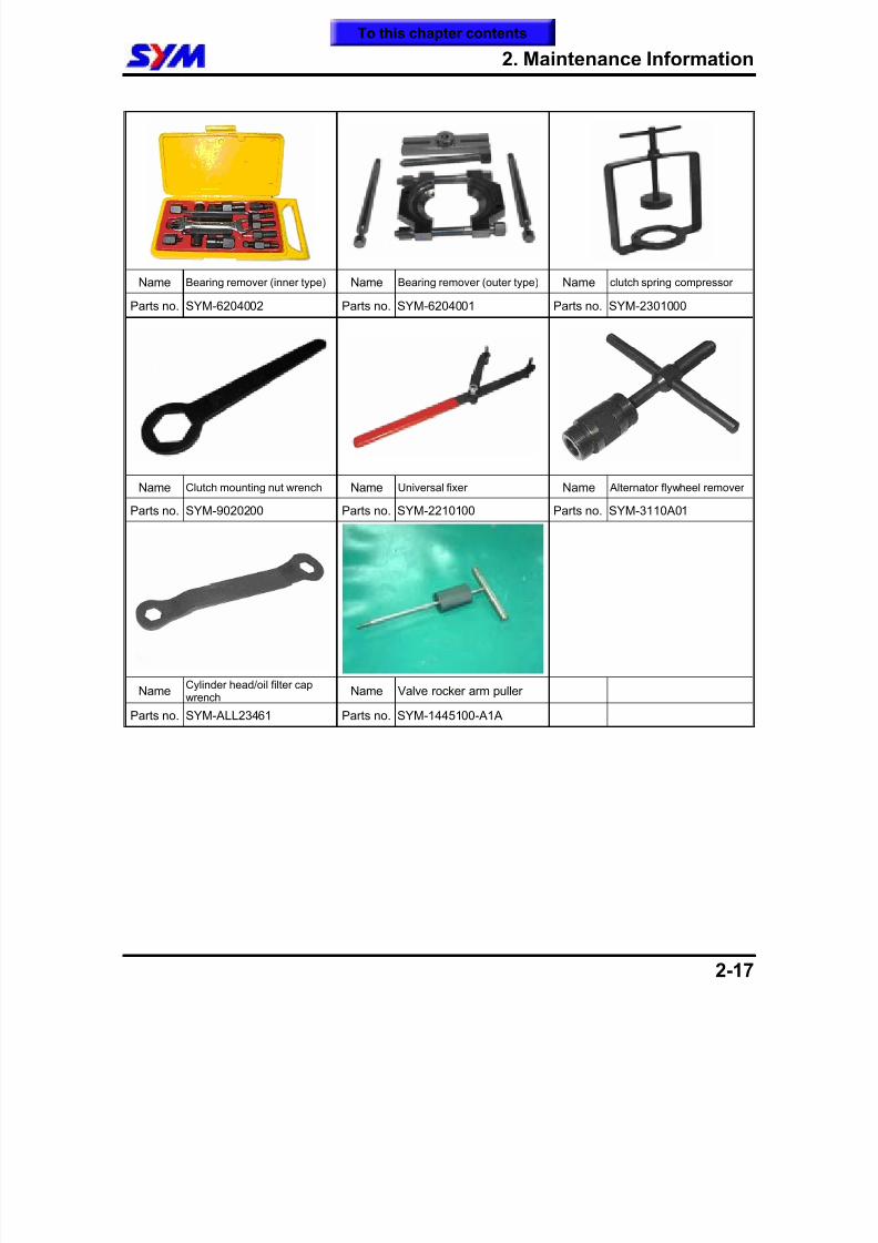
Headlight AdjustmentTurn on main switchTurn the headlight adjustment screw to adjustheadlight beam height.
Caution
To adjust the headlight beam follows relatedregulations.
Improper headlight beam adjustment willmake in coming driver dazzled or insufficientlighting.
Nuts¡ Bolts TightnessPerform periodical maintenance in accord with thePeriodical Maintenance ScheduleCheck if all bolts and nuts on the frame aretightened securely.Check all fixing pins, snap rings, hose (pipe)clamps, and wire holders for security.
Headlight adjustment screw
To this chapter contents
8/12/2019 SYM Mio50 Service Manual 000
http://slidepdf.com/reader/full/sym-mio50-service-manual-000 39/215
2. Maintenance Information
2-16
Special Service Tools Catalogue
NamePuller/presser for crankcasebushing
NamePuller/presser for crankcasebushing
Name Valve spring compressor
Parts no. SYM-1120310 Parts no. SYM-1120320 Parts no. SYM-1471110/20
Name Valve spring compressor NameValve clearance adjustmentwrench
Name Valve clearance adjuster
Parts no. SYM-1471100 Parts no. SYM-9001200 Parts no. SYM-9001210
Name Oil seal tapping installer Name Valve spring compressor Name Valve spring compressor
Parts no. SYM-9121600 Parts no. SYM-9120200 Parts no. SYM-9125500
Name Bearing installer Name Bearing installer Name Bearing installer £r 17mm
Parts no. SYM-9110400 Parts no. SYM-9610000 Parts no. SYM-9620000
(ø28mm) (ø20mm)
(20*32*6)(25*37*6) (27*42*7)
(6301) (6203/6004UZ)(6204)
To this chapter contents
8/12/2019 SYM Mio50 Service Manual 000
http://slidepdf.com/reader/full/sym-mio50-service-manual-000 40/215
2. Maintenance Information
2-17
Name Bearing remover (inner type) Name Bearing remover (outer type) Name clutch spring compressor
Parts no. SYM-6204002 Parts no. SYM-6204001 Parts no. SYM-2301000
Name Clutch mounting nut wrench Name Universal fixer Name Alternator flywheel remover
Parts no. SYM-9020200 Parts no. SYM-2210100 Parts no. SYM-3110A01
NameCylinder head/oil filter capwrench
Name Valve rocker arm puller
Parts no. SYM-ALL23461 Parts no. SYM-1445100-A1A
To this chapter contents
8/12/2019 SYM Mio50 Service Manual 000
http://slidepdf.com/reader/full/sym-mio50-service-manual-000 41/215
2. Maintenance Information
2-18
NOTE:
To this chapter contents
8/12/2019 SYM Mio50 Service Manual 000
http://slidepdf.com/reader/full/sym-mio50-service-manual-000 42/215
3. Lubrication System
3-1
Mechanism Illustrations ····················· 3-1
Operational Precautions····················· 3-2
Trouble Diagnosis ······························· 3-2
Engine OIL ··········································· 3-3
Cleaning Engine Oil Strainer···············3-4
Oil Pump ···············································3-5
Gear Oil ················································· 3-8
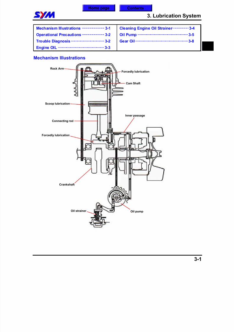
Mechanism Illustrations
3
Rock Arm
Cam Shaft
Scoop lubrication
Forcedly lubrication
Forcedly lubrication
Inner passage
Connecting rod
Oil pumpOil strainer
Crankshaft
Home page Contents
8/12/2019 SYM Mio50 Service Manual 000
http://slidepdf.com/reader/full/sym-mio50-service-manual-000 43/215
3. Lubrication System
3-2
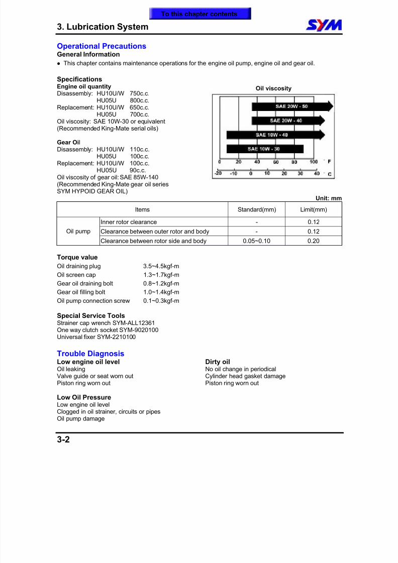
Operational PrecautionsGeneral Information
This chapter contains maintenance operations for the engine oil pump, engine oil and gear oil.
SpecificationsEngine oil quantityDisassembly: HU10U/W 750c.c.
HU05U 800c.c. Replacement: HU10U/W 650c.c.
HU05U 700c.c. Oil viscosity: SAE 10W-30 or equivalent(Recommended King-Mate serial oils)
Gear OilDisassembly: HU10U/W 110c.c.
HU05U 100c.c.
Replacement: HU10U/W 100c.c.HU05U 90c.c.
Oil viscosity of gear oil: SAE 85W-140(Recommended King-Mate gear oil seriesSYM HYPOID GEAR OIL)
Oil viscosity
Unit: mm
Items Standard(mm) Limit(mm)
Inner rotor clearance - 0.12
Clearance between outer rotor and body - 0.12Oil pump
Clearance between rotor side and body 0.05~0.10 0.20
Torque value
Oil draining plug 3.5~4.5kgf-m
Oil screen cap 1.3~1.7kgf-m
Gear oil draining bolt 0.8~1.2kgf-m
Gear oil filling bolt 1.0~1.4kgf-m
Oil pump connection screw 0.1~0.3kgf-m
Special Service ToolsStrainer cap wrench SYM-ALL12361
One way clutch socket SYM-9020100Universal fixer SYM-2210100
Trouble DiagnosisLow engine oil levelOil leaking Valve guide or seat worn out Piston ring worn out
Low Oil PressureLow engine oil level
Clogged in oil strainer, circuits or pipesOil pump damage
Dirty oilNo oil change in periodicalCylinder head gasket damagePiston ring worn out
To this chapter contents
8/12/2019 SYM Mio50 Service Manual 000
http://slidepdf.com/reader/full/sym-mio50-service-manual-000 44/215
8/12/2019 SYM Mio50 Service Manual 000
http://slidepdf.com/reader/full/sym-mio50-service-manual-000 45/215
3. Lubrication System
3-4
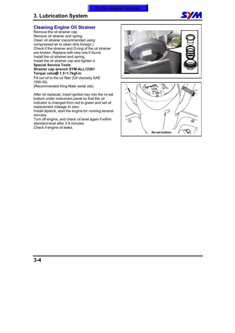
Cleaning Engine Oil StrainerRemove the oil strainer cap.Remove oil strainer and springClean oil strainer (recommended usingcompressed air to clean dirty foreign.)
Check if the strainer and O-ring of the oil strainerare broken. Replace with new one if found.Install the oil strainer and spring.Install the oil strainer cap and tighten it.Special Service Tools:Strainer cap wrench SYM-ALL12361Torque value
¡G
1.3~1.7kgf-m
Fill out oil to the oil filler (Oil viscosity SAE10W-30)(Recommended King-Mate serial oils)
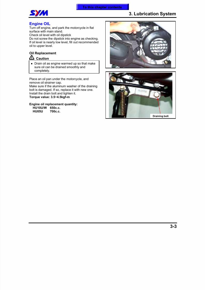
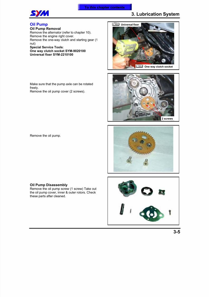
After oil replaced, insert ignition key into the re-setbottom under instrument panel so that the oilindicator is changed from red to green and set oilreplacement mileage to zero.Install dipstick, start the engine for running severalminutes.Turn off engine, and check oil level again if withinstandard level after 3-5 minutes.Check if engine oil leaks.
Re-set bottom
To this chapter contents
8/12/2019 SYM Mio50 Service Manual 000
http://slidepdf.com/reader/full/sym-mio50-service-manual-000 46/215
3. Lubrication System
3-5
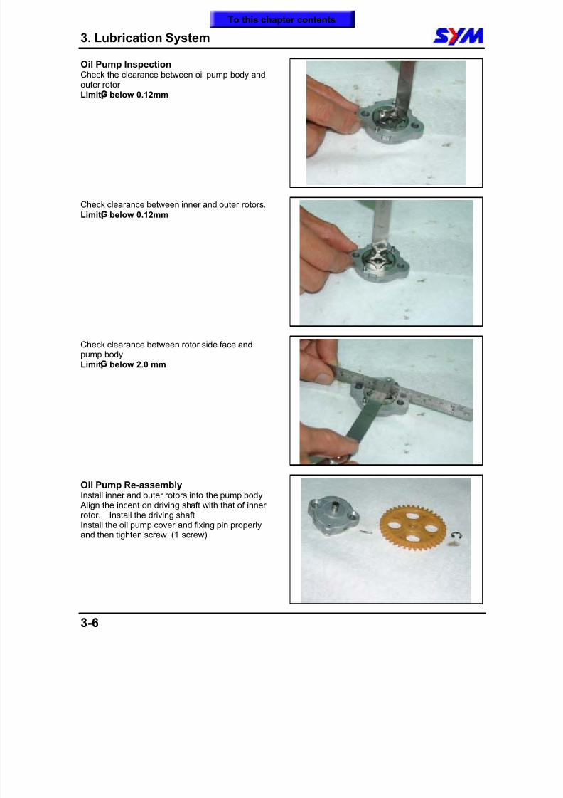
Oil PumpOil Pump RemovalRemove the alternator (refer to chapter 10).Remove the engine right cover.Remove the one-way clutch and starting gear (1
nut)Special Service Tools:One way clutch socket SYM-9020100Universal fixer SYM-2210100
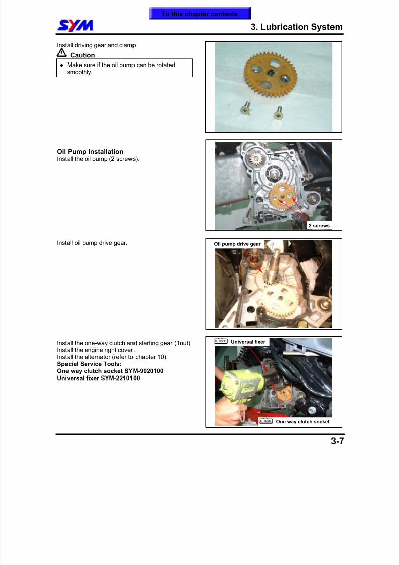
Make sure that the pump axle can be rotatedfreely.Remove the oil pump cover (2 screws).
Remove the oil pump.
Oil Pump DisassemblyRemove the oil pump screw (1 screw) Take outthe oil pump cover, inner & outer rotors. Checkthese parts after cleaned.
2 screws
Universal fixer
One way clutch socket
To this chapter contents
8/12/2019 SYM Mio50 Service Manual 000
http://slidepdf.com/reader/full/sym-mio50-service-manual-000 47/215
3. Lubrication System
3-6
Oil Pump InspectionCheck the clearance between oil pump body andouter rotorLimit¡G below 0.12mm
Check clearance between inner and outer rotors.Limit¡G below 0.12mm
Check clearance between rotor side face andpump bodyLimit¡G below 2.0 mm
Oil Pump Re-assemblyInstall inner and outer rotors into the pump body Align the indent on driving shaft with that of innerrotor. Install the driving shaftInstall the oil pump cover and fixing pin properlyand then tighten screw. (1 screw)
To this chapter contents
8/12/2019 SYM Mio50 Service Manual 000
http://slidepdf.com/reader/full/sym-mio50-service-manual-000 48/215
3. Lubrication System
3-7
Install driving gear and clamp.
Caution
Make sure if the oil pump can be rotatedsmoothly.
Oil Pump InstallationInstall the oil pump (2 screws).
Install oil pump drive gear.
Install the one-way clutch and starting gear (1nut)Install the engine right cover.Install the alternator (refer to chapter 10).Special Service Tools:One way clutch socket SYM-9020100Universal fixer SYM-2210100
Oil pump drive gear
2 screws
Universal fixer
One way clutch socket
To this chapter contents
8/12/2019 SYM Mio50 Service Manual 000
http://slidepdf.com/reader/full/sym-mio50-service-manual-000 49/215
3. Lubrication System
3-8
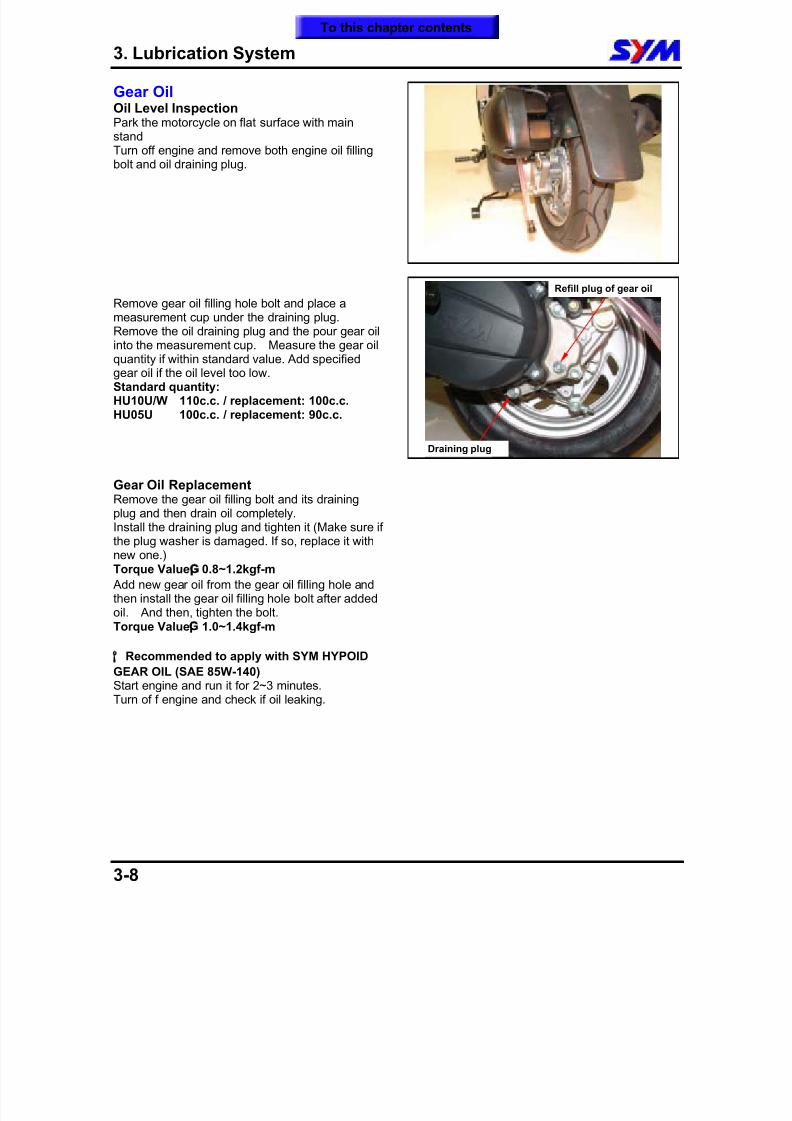
Gear OilOil Level InspectionPark the motorcycle on flat surface with mainstandTurn off engine and remove both engine oil filling
bolt and oil draining plug.
Remove gear oil filling hole bolt and place ameasurement cup under the draining plug.Remove the oil draining plug and the pour gear oilinto the measurement cup. Measure the gear oilquantity if within standard value. Add specifiedgear oil if the oil level too low.Standard quantity:HU10U/W 110c.c. / replacement: 100c.c.HU05U 100c.c. / replacement: 90c.c.
Gear Oil ReplacementRemove the gear oil filling bolt and its drainingplug and then drain oil completely.Install the draining plug and tighten it (Make sure ifthe plug washer is damaged. If so, replace it withnew one.)Torque Value¡G 0.8~1.2kgf-m
Add new gear oil from the gear oil filling hole andthen install the gear oil filling hole bolt after addedoil. And then, tighten the bolt.Torque Value¡G 1.0~1.4kgf-m
¡°
Recommended to apply with SYM HYPOIDGEAR OIL (SAE 85W-140)Start engine and run it for 2~3 minutes.Turn of f engine and check if oil leaking.
Refill plug of gear oil
Draining plug
To this chapter contents
8/12/2019 SYM Mio50 Service Manual 000
http://slidepdf.com/reader/full/sym-mio50-service-manual-000 50/215
4. Fuel System
4-1
Mechanism Illustration ......................4-1
Operational Precautions....................4-2
Trouble Diagnosis..............................4-3
Carburetor...........................................4-4
Idle Speed Adjustment ...................... 4-8
Fuel Tank............................................ 4-9
Air Cleaner.......................................... 4-11
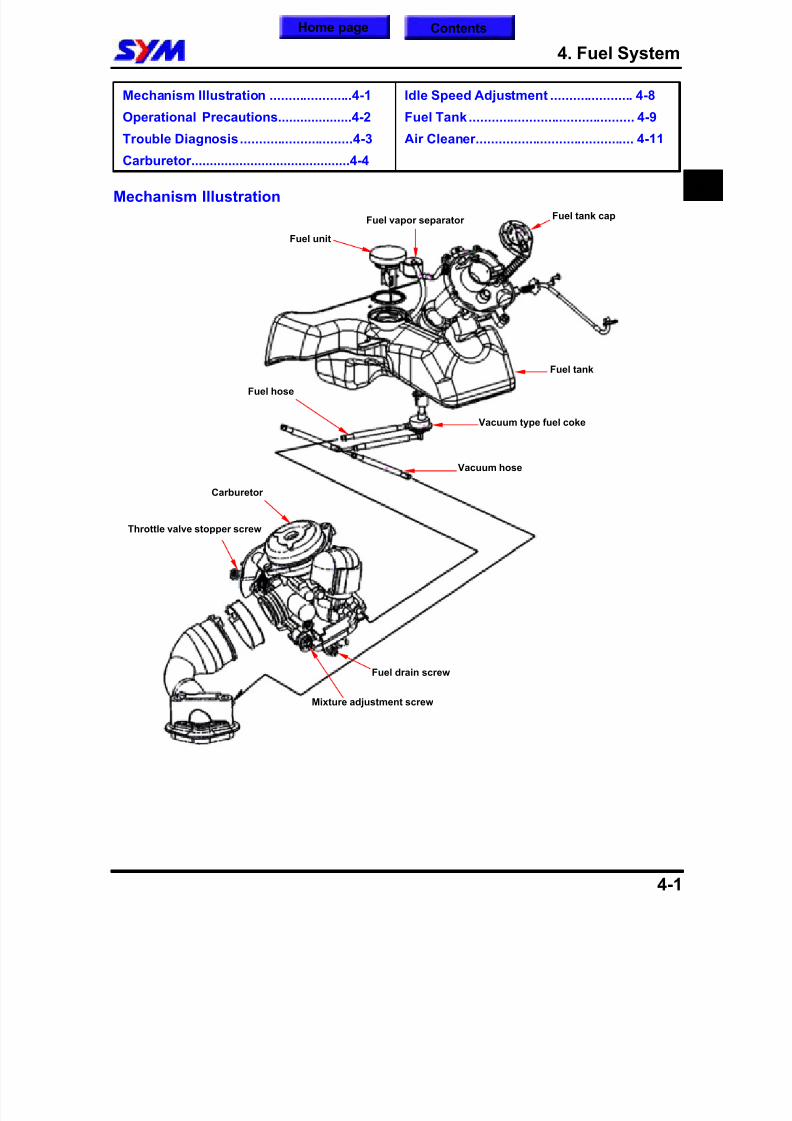
Mechanism Illustration Fuel tank capFuel vapor separator
Fuel unit
Fuel tank
Vacuum hose
Vacuum type fuel coke
Carburetor
Fuel hose
Fuel drain screw
Mixture adjustment screw
Throttle valve stopper screw
4
Home page Contents
8/12/2019 SYM Mio50 Service Manual 000
http://slidepdf.com/reader/full/sym-mio50-service-manual-000 51/215
4. Fuel System
4-2
Operational Precautions
General Information
Warning
Gasoline is a low ignition point and explosive materials, so always work in a well-ventilated place andstrictly prohibit flame when working with gasoline.
Caution
Do not bend or twist throttle valve cable. Damaged cable will make unstable drive ability. When disassembling fuel system parts, pay attention to O-ring position, replace with new one as
re-assembly There is a drain screw in the float chamber for draining residual gasoline. Do not disassemble automatic by-starter and air cut-off valves arbitrarily.
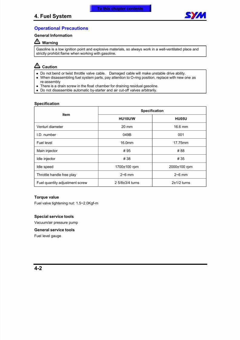
Specification
SpecificationItem
HU10U/W HU05U
Venturi diameter 20 mm 16.6 mm
I.D. number 049B 001
Fuel level 16.0mm 17.75mm
Main injector # 95 # 88
Idle injector # 38 # 35
Idle speed 1700±100 rpm 2000±100 rpm
Throttle handle free play 2~6 mm 2~6 mm
Fuel quantity adjustment screw 2 5/8±3/4 turns 2±1/2 turns
Torque valueFuel valve tightening nut: 1.5~2.0Kgf-m
Special service tools
Vacuum/air pressure pump
General service tools
Fuel level gauge
To this chapter contents
8/12/2019 SYM Mio50 Service Manual 000
http://slidepdf.com/reader/full/sym-mio50-service-manual-000 52/215
4. Fuel System
4-3
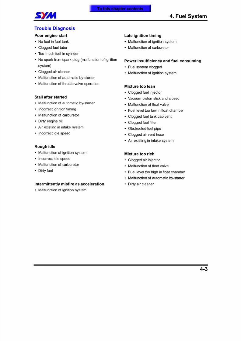
Trouble Diagnosis
Poor engine start
No fuel in fuel tank
Clogged fuel tube
Too much fuel in cylinder
No spark from spark plug (malfunction of ignition
system)
Clogged air cleaner
Malfunction of automatic by-starter
Malfunction of throttle valve operation
Stall after started
Malfunction of automatic by-starter
Incorrect ignition timing
Malfunction of carburetor
Dirty engine oil
Air existing in intake system
Incorrect idle speed
Rough idle
Malfunction of ignition system
Incorrect idle speed
Malfunction of carburetor
Dirty fuel
Intermittently misfire as acceleration
Malfunction of ignition system
Late ignition timing
Malfunction of ignition system
Malfunction of carburetor
Power insufficiency and fuel consuming
Fuel system clogged
Malfunction of ignition system
Mixture too lean
Clogged fuel injector
Vacuum piston stick and closed Malfunction of float valve
Fuel level too low in float chamber
Clogged fuel tank cap vent
Clogged fuel filter
Obstructed fuel pipe
Clogged air vent hose
Air existing in intake system
Mixture too rich
Clogged air injector
Malfunction of float valve
Fuel level too high in float chamber
Malfunction of automatic by-starter
Dirty air cleaner
To this chapter contents

8/12/2019 SYM Mio50 Service Manual 000
http://slidepdf.com/reader/full/sym-mio50-service-manual-000 53/215
4. Fuel System
4-4
Carburetor
Carburetor RemovalRemove the luggage box and seat.Loosen the adjustment nut and fixing nut of throttle
valve cable, and release the cable fromcarburetor.Remove fuel pipe, vacuum hose.Remove air cut-off valve hoseDisconnect automatic by-starter connectors.Release the clamp strip of air cleaner.Release the clamp strip of carburetor isolator.Take the carburetor out.
Vacuum Chamber RemovalLoosen drain screw, and drain out residual fuel in
float chamber.Remove screws (2 screws) of vacuum chambercover and the cover.
Remove compress spring and vacuum piston.
Remove fuel needle seat, spring, and injectorneedle.Check if the vacuum piston for wear out, crack orother damage.Check if the diaphragm for damage or crack.
Caution
Do not damage vacuum diaphragm.
InstallationInstall in reverse order of removal procedures.
2 Screws
Adjustment nut
Heat-isolator clampAir cleaner clamp
To this chapter contents
8/12/2019 SYM Mio50 Service Manual 000
http://slidepdf.com/reader/full/sym-mio50-service-manual-000 54/215
4. Fuel System
4-5
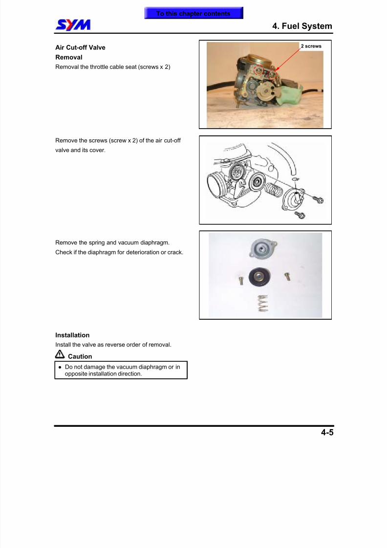
Air Cut-off Valve
Removal
Removal the throttle cable seat (screws x 2)
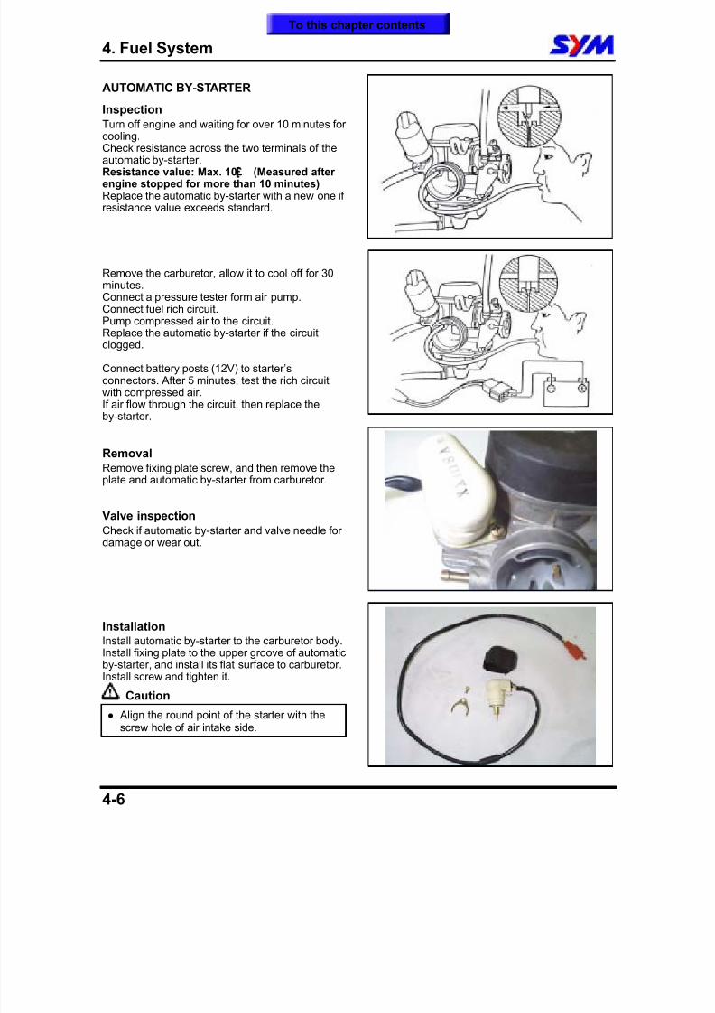
Remove the screws (screw x 2) of the air cut-off
valve and its cover.
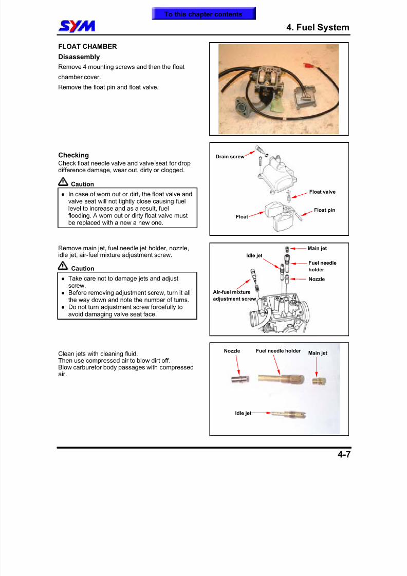
Remove the spring and vacuum diaphragm.
Check if the diaphragm for deterioration or crack.
Installation
Install the valve as reverse order of removal.
Caution
Do not damage the vacuum diaphragm or inopposite installation direction.
2 screws
To this chapter contents
8/12/2019 SYM Mio50 Service Manual 000
http://slidepdf.com/reader/full/sym-mio50-service-manual-000 55/215
4. Fuel System
4-6
AUTOMATIC BY-STARTER
InspectionTurn off engine and waiting for over 10 minutes forcooling.
Check resistance across the two terminals of theautomatic by-starter.Resistance value: Max. 10£ (Measured afterengine stopped for more than 10 minutes)Replace the automatic by-starter with a new one ifresistance value exceeds standard.
Remove the carburetor, allow it to cool off for 30minutes.
Connect a pressure tester form air pump.Connect fuel rich circuit.Pump compressed air to the circuit.Replace the automatic by-starter if the circuitclogged.
Connect battery posts (12V) to starter’sconnectors. After 5 minutes, test the rich circuitwith compressed air.If air flow through the circuit, then replace theby-starter.
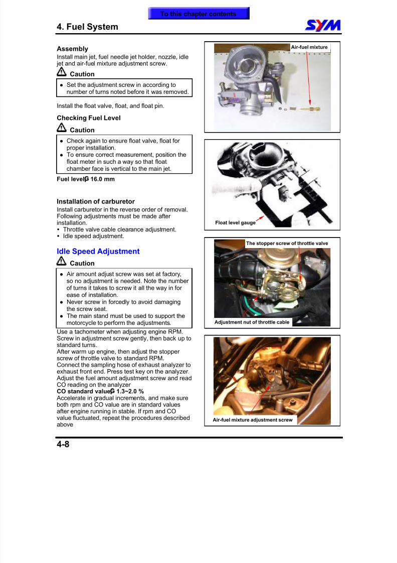
Removal Remove fixing plate screw, and then remove theplate and automatic by-starter from carburetor.
Valve inspectionCheck if automatic by-starter and valve needle fordamage or wear out.
InstallationInstall automatic by-starter to the carburetor body.Install fixing plate to the upper groove of automaticby-starter, and install its flat surface to carburetor.Install screw and tighten it.
Caution
Align the round point of the starter with thescrew hole of air intake side.
To this chapter contents
8/12/2019 SYM Mio50 Service Manual 000
http://slidepdf.com/reader/full/sym-mio50-service-manual-000 56/215
4. Fuel System
4-7
FLOAT CHAMBER
Disassembly
Remove 4 mounting screws and then the float
chamber cover.
Remove the float pin and float valve.
CheckingCheck float needle valve and valve seat for dropdifference damage, wear out, dirty or clogged.
Caution
In case of worn out or dirt, the float valve andvalve seat will not tightly close causing fuellevel to increase and as a result, fuelflooding. A worn out or dirty float valve mustbe replaced with a new a new one.
Remove main jet, fuel needle jet holder, nozzle,idle jet, air-fuel mixture adjustment screw.
Caution
Take care not to damage jets and adjustscrew.
Before removing adjustment screw, turn it allthe way down and note the number of turns.
Do not turn adjustment screw forcefully toavoid damaging valve seat face.
Clean jets with cleaning fluid.Then use compressed air to blow dirt off.Blow carburetor body passages with compressedair.
Float
Float pin
Float valve
Drain screw
Main jet
Idle jet
Nozzle
Fuel needle
holder
Air-fuel mixture
adjustment screw
Main jetNozzle Fuel needle holder
Idle jet
To this chapter contents
8/12/2019 SYM Mio50 Service Manual 000
http://slidepdf.com/reader/full/sym-mio50-service-manual-000 57/215
4. Fuel System
4-8
AssemblyInstall main jet, fuel needle jet holder, nozzle, idle jet and air-fuel mixture adjustment screw.
Caution
Set the adjustment screw in according tonumber of turns noted before it was removed.
Install the float valve, float, and float pin.
Checking Fuel Level
Caution
Check again to ensure float valve, float forproper installation.
To ensure correct measurement, position the
float meter in such a way so that floatchamber face is vertical to the main jet.
Fuel level¡G
16.0 mm
Installation of carburetorInstall carburetor in the reverse order of removal.Following adjustments must be made afterinstallation. Throttle valve cable clearance adjustment. Idle speed adjustment.
Idle Speed Adjustment
Caution
Air amount adjust screw was set at factory,so no adjustment is needed. Note the numberof turns it takes to screw it all the way in forease of installation.
Never screw in forcedly to avoid damagingthe screw seat.
The main stand must be used to support themotorcycle to perform the adjustments.
Use a tachometer when adjusting engine RPM.Screw in adjustment screw gently, then back up tostandard turns. After warm up engine, then adjust the stopperscrew of throttle valve to standard RPM.Connect the sampling hose of exhaust analyzer toexhaust front end. Press test key on the analyzer. Adjust the fuel amount adjustment screw and readCO reading on the analyzerCO standard value¡G 1.3~2.0 % Accelerate in gradual increments, and make sureboth rpm and CO value are in standard values
after engine running in stable. If rpm and COvalue fluctuated, repeat the procedures describedabove
Air-fuel mixture
Float level gauge
Adjustment nut of throttle cable
The stopper screw of throttle valve
Air-fuel mixture adjustment screw
To this chapter contents
8/12/2019 SYM Mio50 Service Manual 000
http://slidepdf.com/reader/full/sym-mio50-service-manual-000 58/215
4. Fuel System
4-9
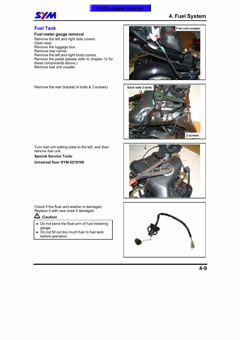
Fuel Tank
Fuel meter gauge removalRemove the left and right side covers.Open seat.Remove the luggage box.Remove rear carrier.Remove the left and right body covers.Remove the pedal (please refer to chapter 12 forthese components above.)Remove fuel unit coupler.
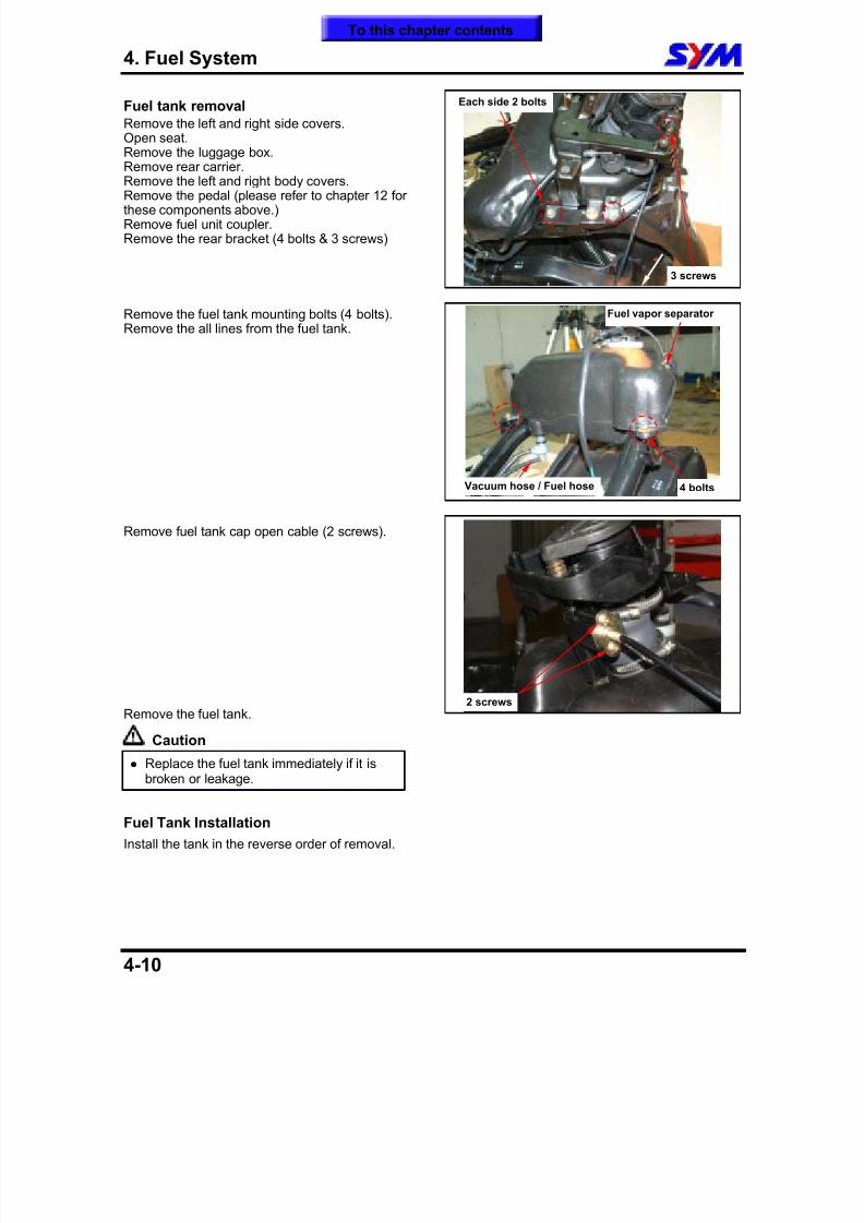
Remove the rear bracket (4 bolts & 3 screws)
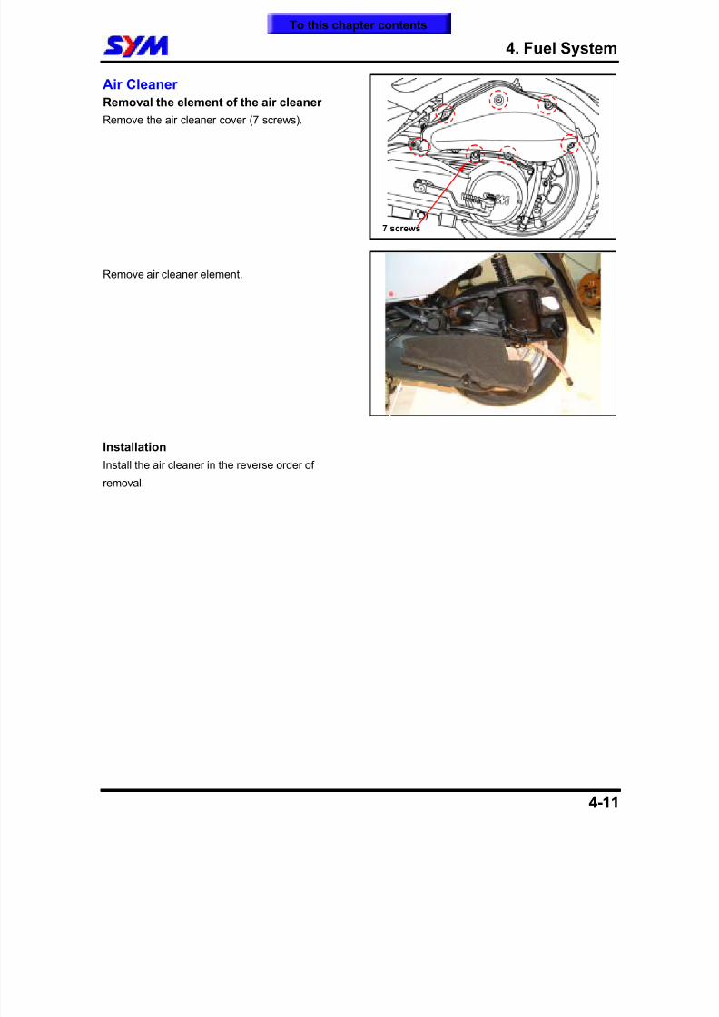
Turn fuel unit setting plate to the left, and thenremove fuel unit.
Special Service Tools:
Universal fixer SYM-2210100
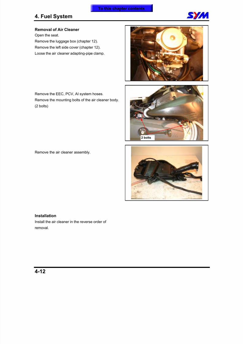
Check if the float and washer is damaged.Replace it with new ones if damaged.
Caution
Do not bend the float arm of fuel meteringgauge.
Do not fill out too much fuel to fuel tankbefore operation.
Fuel unit coupler
Each side 2 bolts
3 screws
To this chapter contents
8/12/2019 SYM Mio50 Service Manual 000
http://slidepdf.com/reader/full/sym-mio50-service-manual-000 59/215
4. Fuel System
4-10
Fuel tank removal Remove the left and right side covers.Open seat.Remove the luggage box.Remove rear carrier.
Remove the left and right body covers.Remove the pedal (please refer to chapter 12 forthese components above.)Remove fuel unit coupler.Remove the rear bracket (4 bolts & 3 screws)
Remove the fuel tank mounting bolts (4 bolts).Remove the all lines from the fuel tank.
Remove fuel tank cap open cable (2 screws).
Remove the fuel tank.
Caution
Replace the fuel tank immediately if it isbroken or leakage.
Fuel Tank Installation
Install the tank in the reverse order of removal.
Vacuum hose / Fuel hose
Fuel vapor separator
4 bolts
2 screws
Each side 2 bolts
3 screws
To this chapter contents
8/12/2019 SYM Mio50 Service Manual 000
http://slidepdf.com/reader/full/sym-mio50-service-manual-000 60/215
4. Fuel System
4-11
Air Cleaner
Removal the element of the air cleaner
Remove the air cleaner cover (7 screws).
Remove air cleaner element.
Installation
Install the air cleaner in the reverse order of
removal.
7 screws
To this chapter contents
8/12/2019 SYM Mio50 Service Manual 000
http://slidepdf.com/reader/full/sym-mio50-service-manual-000 61/215
4. Fuel System
4-12
Removal of Air Cleaner
Open the seat.
Remove the luggage box (chapter 12).
Remove the left side cover (chapter 12).
Loose the air cleaner adapting-pipe clamp.
Remove the EEC, PCV, AI system hoses.
Remove the mounting bolts of the air cleaner body.
(2 bolts)
Remove the air cleaner assembly.
Installation
Install the air cleaner in the reverse order of
removal.
2 bolts
To this chapter contents
8/12/2019 SYM Mio50 Service Manual 000
http://slidepdf.com/reader/full/sym-mio50-service-manual-000 62/215
5. Removal & Installation of Engine
5-1
Mechanism Illustrations ····················· 5-1
Operational Precautions····················· 5-2
Engine Removal ·································· 5-3
Removal of Engine Bush····················· 5-6
Engine Hanger······································5-7
Installation of Engine··························· 5-8
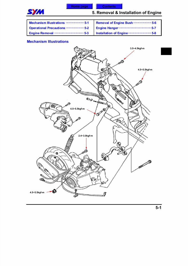
Mechanism Illustrations
5
3.5~4.5kgf-m
2.4~3.0kgf-m
4.5~5.5kgf-m
4.5~5.5kgf-m
4.5~5.5kgf-m
Home page Contents
8/12/2019 SYM Mio50 Service Manual 000
http://slidepdf.com/reader/full/sym-mio50-service-manual-000 63/215
5. Removal & Installation of Engine
5-2
Operational PrecautionsGeneral Information Engine must be supported by a bracket or adjustable tool in height. The following parts can be serviced with the engine installed on the frame.
1. Carburetor
2. Driving disk, driving belt, clutch, and transporting disk3. Final reduction gear mechanism
Specification
Specification Item
MIO 50 MIO 100
Replacement 700 c.c. 650 c.c.Engine Oil Capacity
Disassemble 800 c.c. 750 c.c.
Replacement 90 c.c. 100 c.c.Gear Oil Capacity
Disassemble 100 c.c. 110 c.c.
Torque Values
Engine hanger bolt (frame side) 4.5~5.5kgf-m
Engine hanger nut (engine side) 4.5~5.5kgf-m
Bolt of rear cushion upper connection 3.5~4.5kgf-m
Bolt of rear cushion lower connection 2.4~3.0kgf-m
To this chapter contents
8/12/2019 SYM Mio50 Service Manual 000
http://slidepdf.com/reader/full/sym-mio50-service-manual-000 64/215
5. Removal & Installation of Engine
5-3
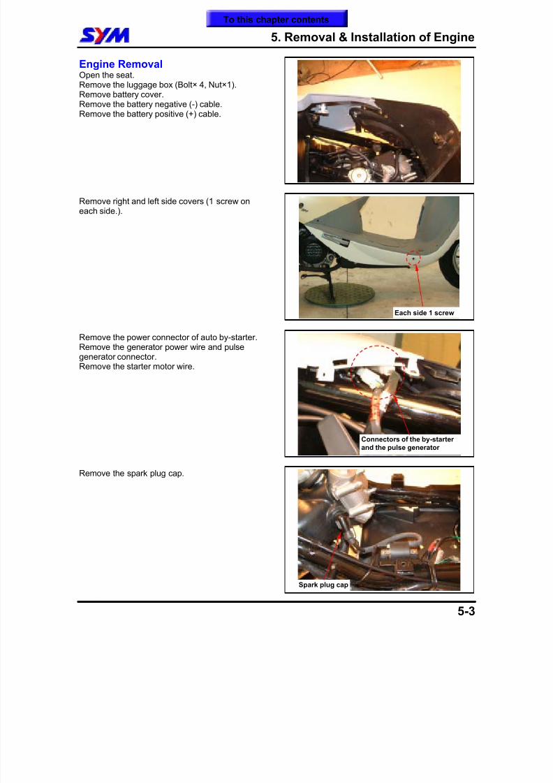
Engine RemovalOpen the seat.Remove the luggage box (Bolt× 4, Nut×1).Remove battery cover.Remove the battery negative (-) cable.
Remove the battery positive (+) cable.
Remove right and left side covers (1 screw oneach side.).
Remove the power connector of auto by-starter.Remove the generator power wire and pulsegenerator connector.Remove the starter motor wire.
Remove the spark plug cap.
Connectors of the by-starterand the pulse generator
Spark plug cap
Each side 1 screw
To this chapter contents
8/12/2019 SYM Mio50 Service Manual 000
http://slidepdf.com/reader/full/sym-mio50-service-manual-000 65/215
5. Removal & Installation of Engine
5-4
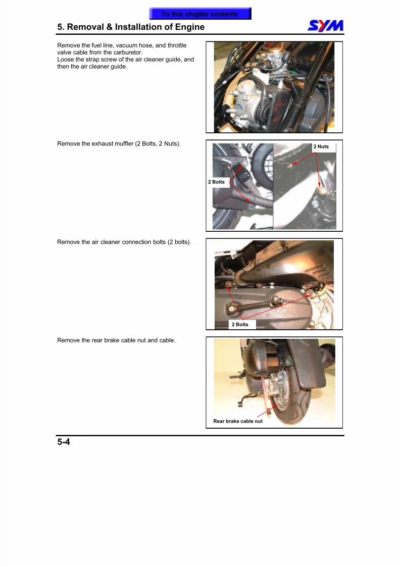
Remove the fuel line, vacuum hose, and throttlevalve cable from the carburetor.Loose the strap screw of the air cleaner guide, andthen the air cleaner guide.
Remove the exhaust muffler (2 Bolts, 2 Nuts).
Remove the air cleaner connection bolts (2 bolts).
Remove the rear brake cable nut and cable.
2 Nuts
2 Bolts
2 Bolts
Rear brake cable nut
To this chapter contents
8/12/2019 SYM Mio50 Service Manual 000
http://slidepdf.com/reader/full/sym-mio50-service-manual-000 66/215
5. Removal & Installation of Engine
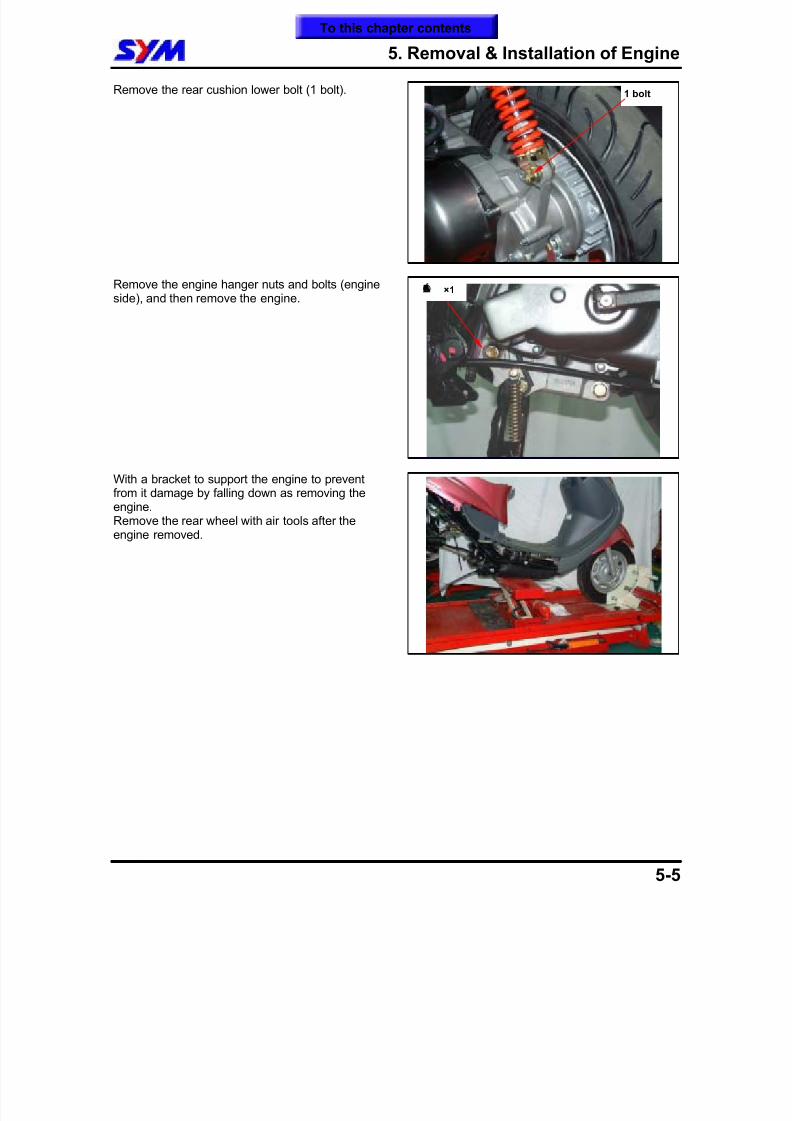
5-5
Remove the rear cushion lower bolt (1 bolt).
Remove the engine hanger nuts and bolts (engineside), and then remove the engine.
With a bracket to support the engine to prevent
from it damage by falling down as removing theengine.Remove the rear wheel with air tools after theengine removed.
1 bolt
Á® ×1
To this chapter contents
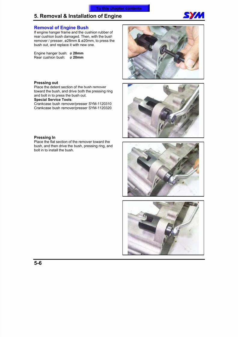
8/12/2019 SYM Mio50 Service Manual 000
http://slidepdf.com/reader/full/sym-mio50-service-manual-000 67/215
5. Removal & Installation of Engine
5-6
Removal of Engine BushIf engine hanger frame and the cushion rubber ofrear cushion bush damaged. Then, with the bushremover / presser, ø28mm & ø20mm, to press thebush out, and replace it with new one.
Engine hanger bush: ø 28mm Rear cushion bush: ø 20mm
Pressing outPlace the detent section of the bush removertoward the bush, and drive both the pressing ringand bolt in to press the bush out.Special Service Tools:Crankcase bush remover/presser SYM-1120310Crankcase bush remover/presser SYM-1120320
Pressing InPlace the flat section of the remover toward the
bush, and then drive the bush, pressing ring, andbolt in to install the bush.
To this chapter contents
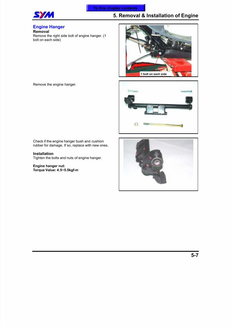
8/12/2019 SYM Mio50 Service Manual 000
http://slidepdf.com/reader/full/sym-mio50-service-manual-000 68/215
5. Removal & Installation of Engine
5-7
Engine HangerRemovalRemove the right side bolt of engine hanger. (1bolt on each side)
Remove the engine hanger.
Check if the engine hanger bush and cushionrubber for damage. If so, replace with new ones.
InstallationTighten the bolts and nuts of engine hanger.
Engine hanger nut:Torque Value: 4.5~5.5kgf-m
1 bolt on each side
To this chapter contents
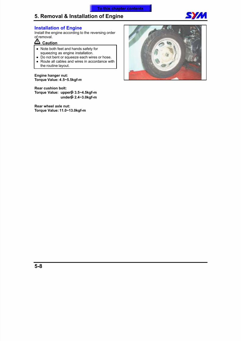
8/12/2019 SYM Mio50 Service Manual 000
http://slidepdf.com/reader/full/sym-mio50-service-manual-000 69/215
5. Removal & Installation of Engine
5-8
Installation of EngineInstall the engine according to the reversing orderof removal.
Caution
Note both feet and hands safety forsqueezing as engine installation.
Do not bent or squeeze each wires or hose. Route all cables and wires in accordance with
the routine layout.
Engine hanger nut:Torque Value: 4.5~5.5kgf-m
Rear cushion bolt:Torque Value: upper ¡G 3.5~4.5kgf-m
under ¡G 2.4~3.0kgf-m
Rear wheel axle nut:Torque Value: 11.0~13.0kgf-m
To this chapter contents
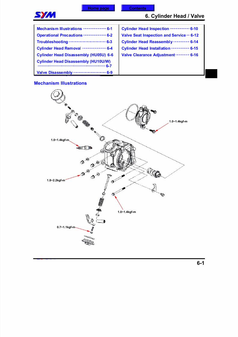
8/12/2019 SYM Mio50 Service Manual 000
http://slidepdf.com/reader/full/sym-mio50-service-manual-000 70/215
6. Cylinder Head / Valve
6-1
Mechanism Illustrations ····················· 6-1
Operational Precautions····················· 6-2
Troubleshooting ·································· 6-3
Cylinder Head Removal ······················ 6-4
Cylinder Head Disassembly (HU05U) 6-6
Cylinder Head Disassembly (HU10U/W)······························································ 6-7
Valve Disassembly ······························ 6-9
Cylinder Head Inspection ·················· 6-10
Valve Seat Inspection and Service··· 6-12
Cylinder Head Reassembly··············· 6-14
Cylinder Head Installation················· 6-15
Valve Clearance Adjustment············· 6-16
Mechanism Illustrations
6
Home page Contents
1.0~1.4kgf-m
0.7~1.1kgf-m
1.0~1.4kgf-m
1.8~2.2kgf-m
1.0~1.4kgf-m
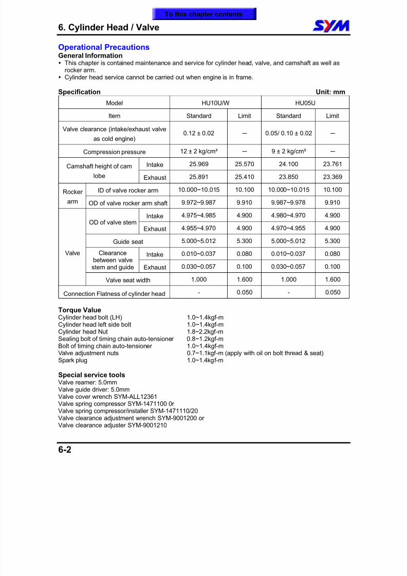
8/12/2019 SYM Mio50 Service Manual 000
http://slidepdf.com/reader/full/sym-mio50-service-manual-000 71/215
6. Cylinder Head / Valve
6-2
Operational PrecautionsGeneral Information This chapter is contained maintenance and service for cylinder head, valve, and camshaft as well as
rocker arm. Cylinder head service cannot be carried out when engine is in frame.
Specification Unit: mm
Model HU10U/W HU05U
Item Standard Limit Standard Limit
Valve clearance (intake/exhaust valve
as cold engine) 0.12 ± 0.02 0.05/ 0.10 ± 0.02
Compression pressure 12 ± 2 kg/cm² 9 ± 2 kg/cm²
Intake25.969 25.570 24.100 23.761
Camshaft height of camlobe Exhaust 25.891 25.410 23.850 23.369
ID of valve rocker arm 10.000~10.015 10.100 10.000~10.015 10.100Rocker
arm OD of valve rocker arm shaft 9.972~9.987 9.910 9.987~9.978 9.910
Intake 4.975~4.985 4.900 4.980~4.970 4.900OD of valve stem
Exhaust 4.955~4.970 4.900 4.970~4.955 4.900
Guide seat 5.000~5.012 5.300 5.000~5.012 5.300
Intake 0.010~0.037 0.080 0.010~0.037 0.080Clearancebetween valvestem and guide Exhaust 0.030~0.057 0.100 0.030~0.057 0.100
Valve
Valve seat width 1.000 1.600 1.000 1.600
Connection Flatness of cylinder head - 0.050 - 0.050
Torque Value Cylinder head bolt (LH) 1.0~1.4kgf-mCylinder head left side bolt 1.0~1.4kgf-mCylinder head Nut 1.8~2.2kgf-mSealing bolt of timing chain auto-tensioner 0.8~1.2kgf-mBolt of timing chain auto-tensioner 1.0~1.4kgf-mValve adjustment nuts 0.7~1.1kgf-m (apply with oil on bolt thread & seat)Spark plug 1.0~1.4kgf-m
Special service toolsValve reamer: 5.0mmValve guide driver: 5.0mmValve cover wrench SYM-ALL12361Valve spring compressor SYM-1471100 0rValve spring compressor/installer SYM-1471110/20
Valve clearance adjustment wrench SYM-9001200 orValve clearance adjuster SYM-9001210
To this chapter contents
8/12/2019 SYM Mio50 Service Manual 000
http://slidepdf.com/reader/full/sym-mio50-service-manual-000 72/215
6. Cylinder Head / Valve
6-3
Troubleshooting
Engine performance will be affected by troubles on engine top end. The troubles usually can be
determinate or by performing cylinder compression test and judging the abnormal noise generated.
Rough IdleLow compression pressure
Low compression pressure1. Valve
Improper valve adjustment Burnt or bended valve Improper valve timing Valve spring damaged Valve carbon Poor sealing on valve seat Improper spark plug installation
2. Cylinder head Cylinder head gasket leaking or damage Tilt or crack cylinder surface
3. Piston Piston ring worn out
High compression pressure Too much carbon deposit on combustion chamber or piston head
Noise Improper valve clearance adjustment Burnt valve or damaged valve spring Camshaft wear out or damage Cam chain wear out or looseness Auto-tensioner wear out or damage of cam chain Camshaft sprocket wear out Rocker arm or rocker arm shaft wear out
White smoke Valve guide or valve stem wear out Valve stem seal wear out
To this chapter contents
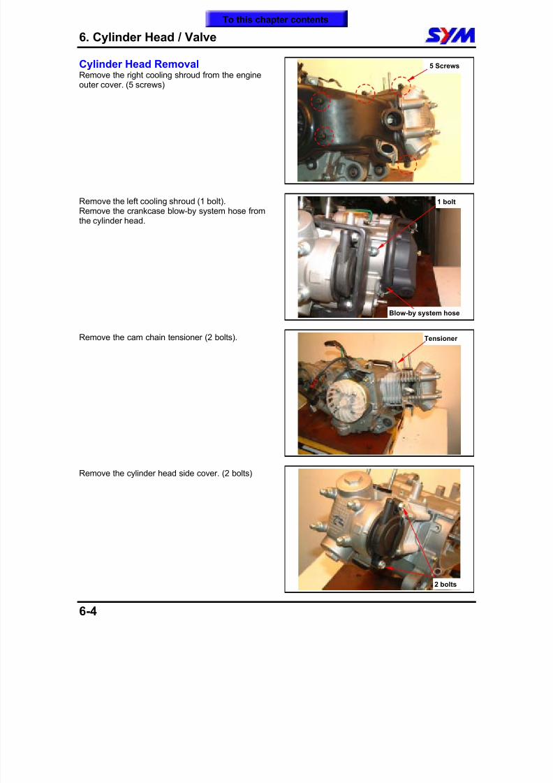
8/12/2019 SYM Mio50 Service Manual 000
http://slidepdf.com/reader/full/sym-mio50-service-manual-000 73/215
6. Cylinder Head / Valve
6-4
Cylinder Head RemovalRemove the right cooling shroud from the engineouter cover. (5 screws)
Remove the left cooling shroud (1 bolt).Remove the crankcase blow-by system hose fromthe cylinder head.
Remove the cam chain tensioner (2 bolts).
Remove the cylinder head side cover. (2 bolts)
5 Screws
Tensioner
2 bolts
Blow-by system hose
1 bolt
To this chapter contents
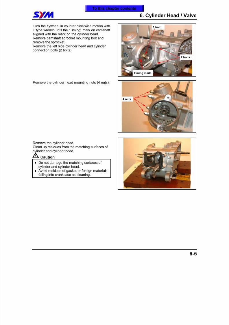
8/12/2019 SYM Mio50 Service Manual 000
http://slidepdf.com/reader/full/sym-mio50-service-manual-000 74/215
6. Cylinder Head / Valve
6-5
Turn the flywheel in counter clockwise motion withT type wrench until the “Timing” mark on camshaftaligned with the mark on the cylinder head.Remove camshaft sprocket mounting bolt andremove the sprocket.
Remove the left side cylinder head and cylinderconnection bolts (2 bolts)
Remove the cylinder head mounting nuts (4 nuts).
Remove the cylinder head.Clean up residues from the matching surfaces ofcylinder and cylinder head.
Caution
Do not damage the matching surfaces ofcylinder and cylinder head.
Avoid residues of gasket or foreign materialsfalling into crankcase as cleaning.
4 nuts
Timing mark
2 bolts
1 bolt
To this chapter contents
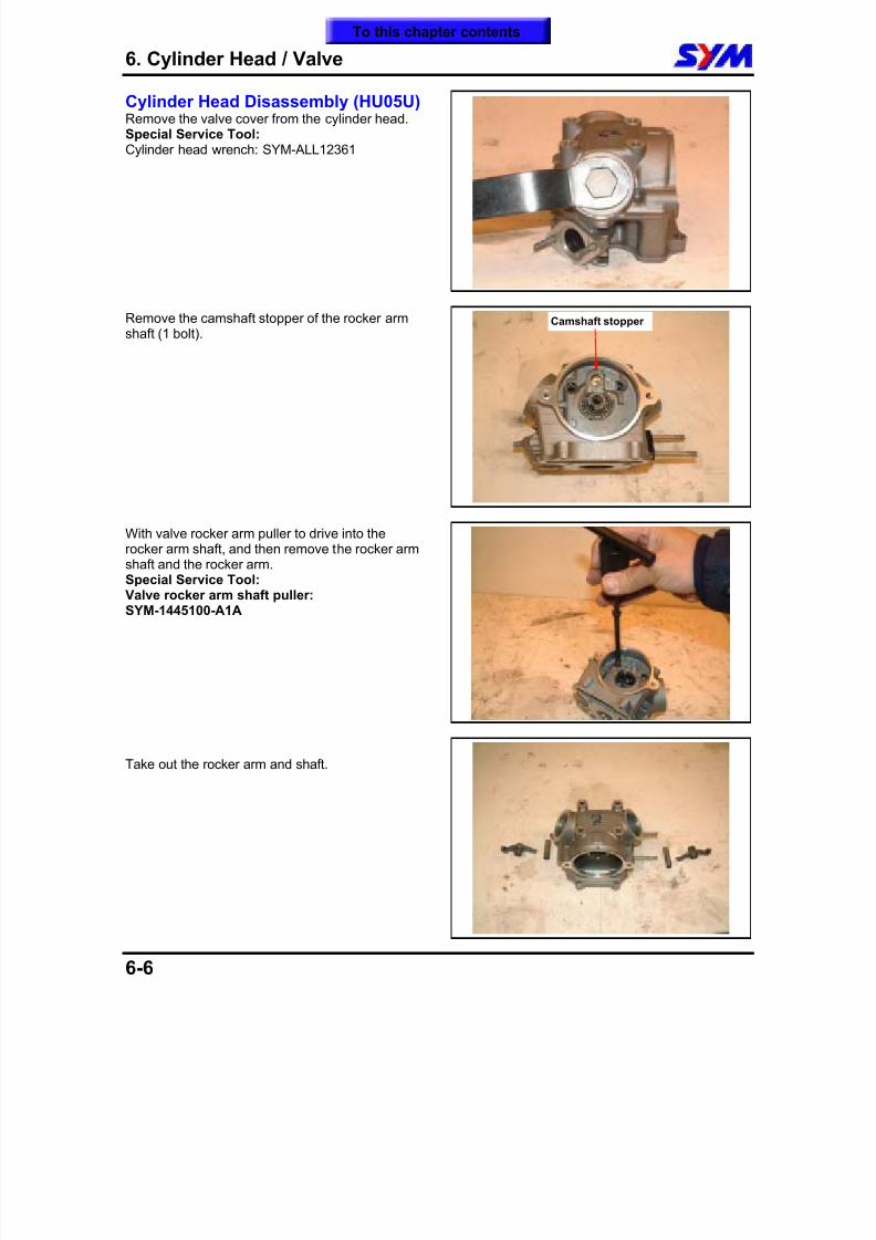
8/12/2019 SYM Mio50 Service Manual 000
http://slidepdf.com/reader/full/sym-mio50-service-manual-000 75/215
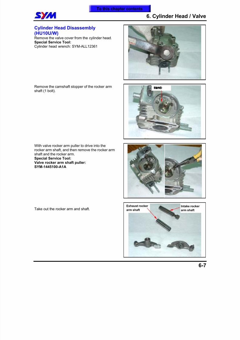
8/12/2019 SYM Mio50 Service Manual 000
http://slidepdf.com/reader/full/sym-mio50-service-manual-000 76/215
6. Cylinder Head / Valve
6-7
Cylinder Head Disassembly(HU10U/W)Remove the valve cover from the cylinder head.Special Service Tool:Cylinder head wrench: SYM-ALL12361
Remove the camshaft stopper of the rocker armshaft (1 bolt).
With valve rocker arm puller to drive into therocker arm shaft, and then remove the rocker armshaft and the rocker arm.Special Service Tool:Valve rocker arm shaft puller:SYM-1445100-A1A
Take out the rocker arm and shaft.
©©¾ªO
Intake rocker
arm shaft
Exhaust rocker
arm shaft
To this chapter contents
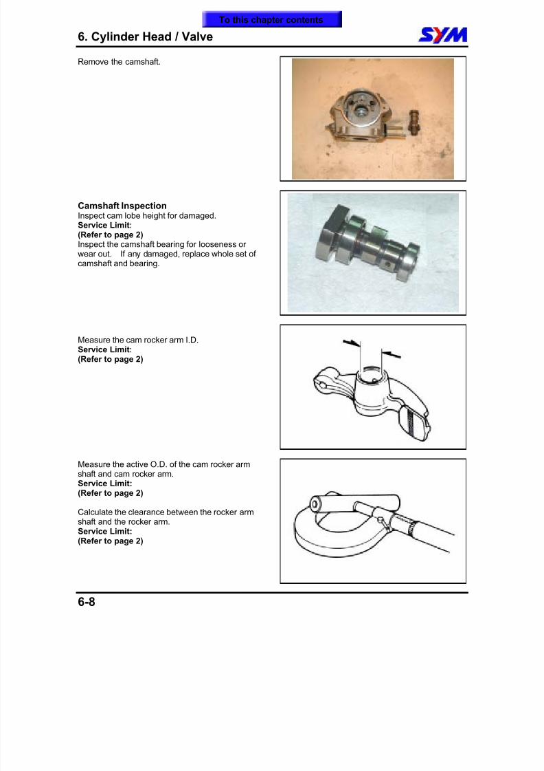
8/12/2019 SYM Mio50 Service Manual 000
http://slidepdf.com/reader/full/sym-mio50-service-manual-000 77/215
6. Cylinder Head / Valve
6-8
Remove the camshaft.
Camshaft InspectionInspect cam lobe height for damaged.
Service Limit:(Refer to page 2)Inspect the camshaft bearing for looseness orwear out. If any damaged, replace whole set ofcamshaft and bearing.
Measure the cam rocker arm I.D.Service Limit:(Refer to page 2)
Measure the active O.D. of the cam rocker armshaft and cam rocker arm.Service Limit:(Refer to page 2)
Calculate the clearance between the rocker armshaft and the rocker arm.Service Limit:(Refer to page 2)
To this chapter contents
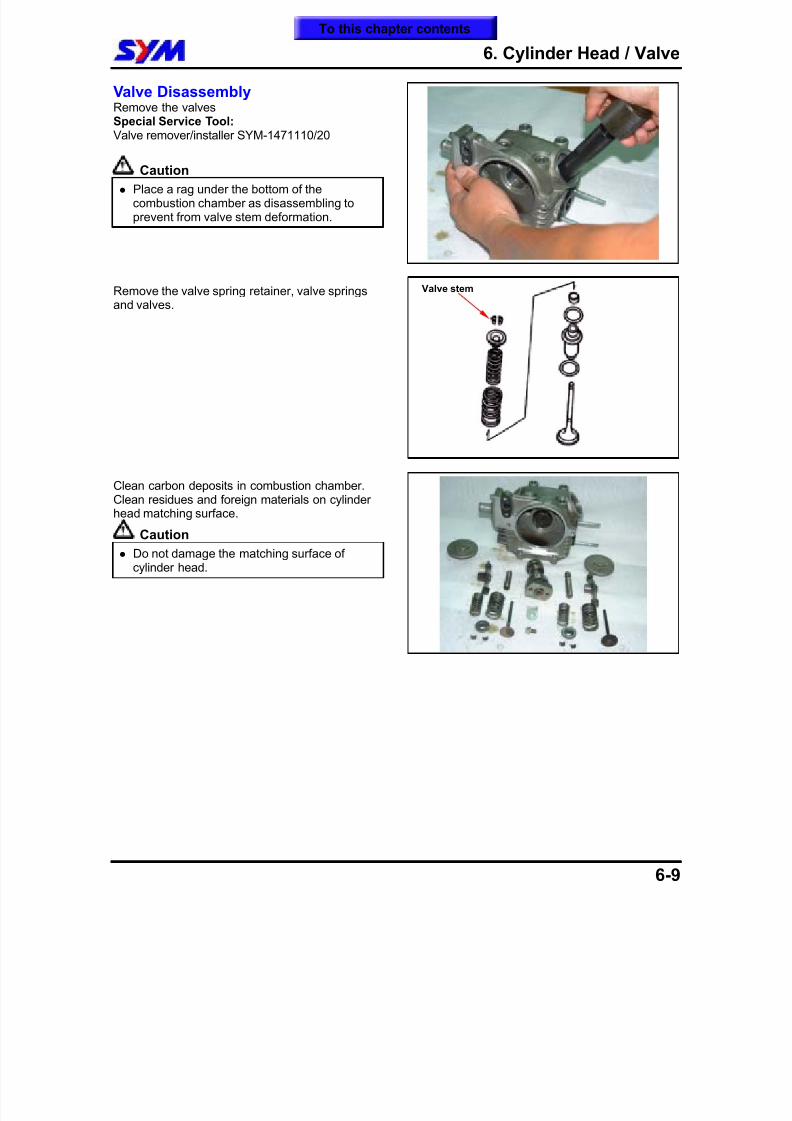
8/12/2019 SYM Mio50 Service Manual 000
http://slidepdf.com/reader/full/sym-mio50-service-manual-000 78/215
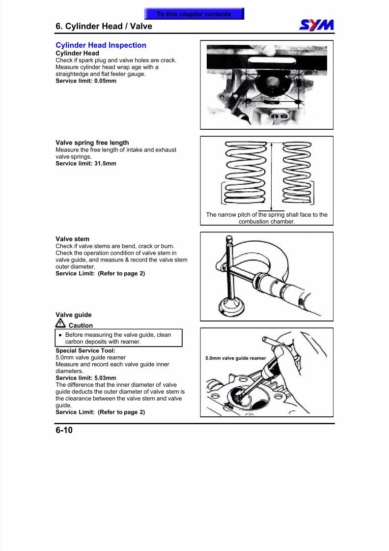
8/12/2019 SYM Mio50 Service Manual 000
http://slidepdf.com/reader/full/sym-mio50-service-manual-000 79/215
6. Cylinder Head / Valve
6-10
Cylinder Head InspectionCylinder HeadCheck if spark plug and valve holes are crack.Measure cylinder head wrap age with astraightedge and flat feeler gauge.
Service limit: 0.05mm
Valve spring free lengthMeasure the free length of intake and exhaustvalve springs.Service limit: 31.5mm
Valve stemCheck if valve stems are bend, crack or burn.Check the operation condition of valve stem invalve guide, and measure & record the valve stemouter diameter.Service Limit: (Refer to page 2)
Valve guide
Caution
Before measuring the valve guide, cleancarbon deposits with reamer.
Special Service Tool:5.0mm valve guide reamerMeasure and record each valve guide innerdiameters.Service limit: 5.03mmThe difference that the inner diameter of valveguide deducts the outer diameter of valve stem is
the clearance between the valve stem and valveguide.Service Limit: (Refer to page 2)
The narrow pitch of the spring shall face to thecombustion chamber.
5.0mm valve guide reamer
To this chapter contents
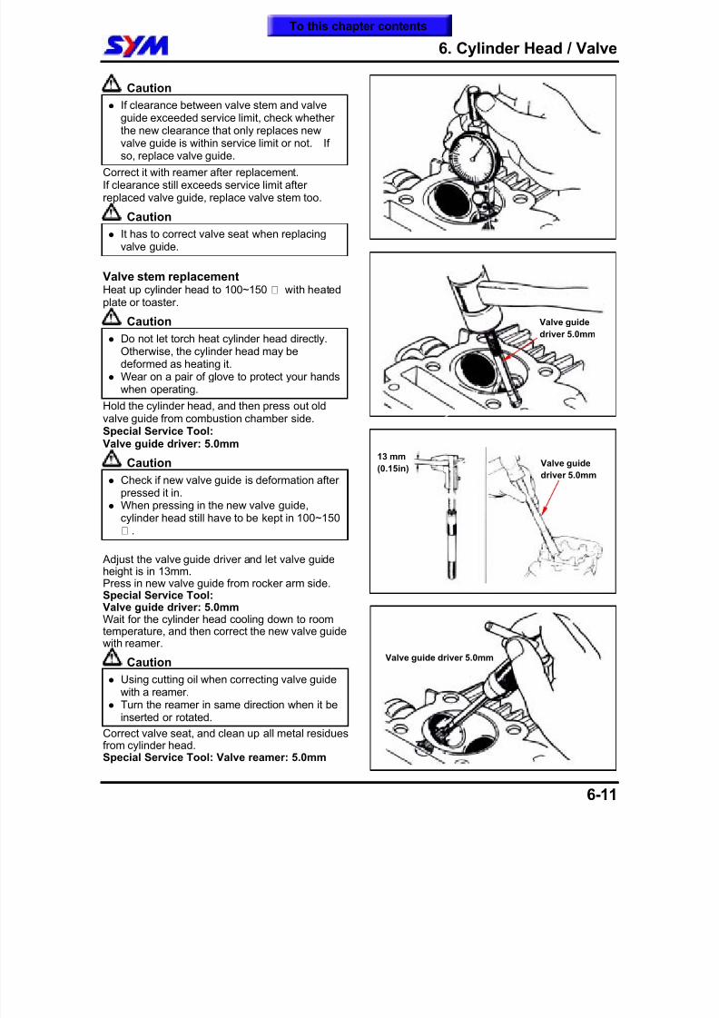
8/12/2019 SYM Mio50 Service Manual 000
http://slidepdf.com/reader/full/sym-mio50-service-manual-000 80/215
6. Cylinder Head / Valve
6-11
Caution
If clearance between valve stem and valveguide exceeded service limit, check whetherthe new clearance that only replaces new
valve guide is within service limit or not. Ifso, replace valve guide. Correct it with reamer after replacement.If clearance still exceeds service limit afterreplaced valve guide, replace valve stem too.
Caution
It has to correct valve seat when replacingvalve guide.
Valve stem replacementHeat up cylinder head to 100~150 ¢J with heatedplate or toaster.
Caution
Do not let torch heat cylinder head directly.Otherwise, the cylinder head may bedeformed as heating it.
Wear on a pair of glove to protect your handswhen operating.
Hold the cylinder head, and then press out oldvalve guide from combustion chamber side.Special Service Tool:
Valve guide driver: 5.0mm
Caution
Check if new valve guide is deformation afterpressed it in.
When pressing in the new valve guide,cylinder head still have to be kept in 100~150¢J .
Adjust the valve guide driver and let valve guideheight is in 13mm.Press in new valve guide from rocker arm side.
Special Service Tool:Valve guide driver: 5.0mmWait for the cylinder head cooling down to roomtemperature, and then correct the new valve guidewith reamer.
Caution
Using cutting oil when correcting valve guidewith a reamer.
Turn the reamer in same direction when it beinserted or rotated.
Correct valve seat, and clean up all metal residuesfrom cylinder head.Special Service Tool: Valve reamer: 5.0mm
Valve guide
driver 5.0mm
13 mm
(0.15in)
Valve guide driver 5.0mm
Valve guide
driver 5.0mm
To this chapter contents
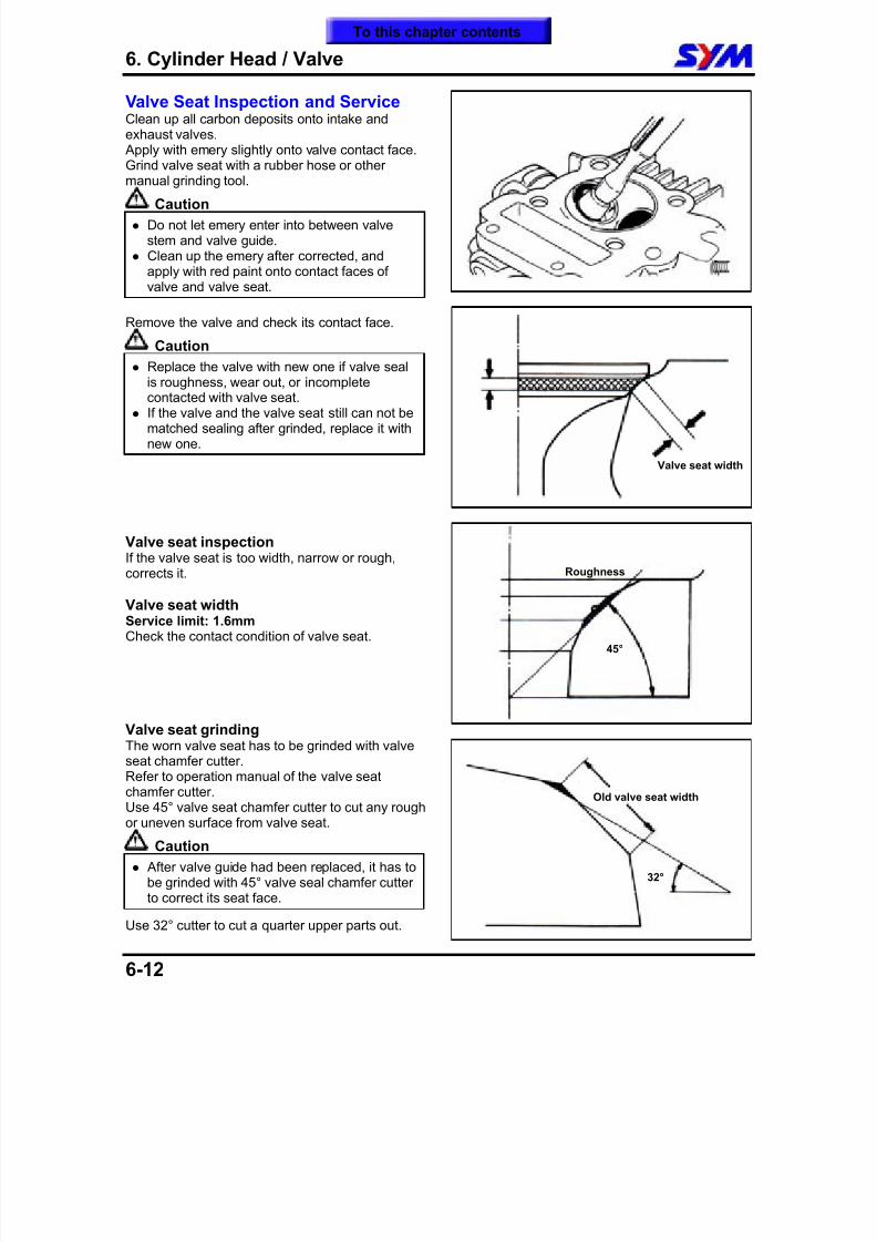
8/12/2019 SYM Mio50 Service Manual 000
http://slidepdf.com/reader/full/sym-mio50-service-manual-000 81/215
6. Cylinder Head / Valve
6-12
Valve Seat Inspection and ServiceClean up all carbon deposits onto intake andexhaust valves. Apply with emery slightly onto valve contact face.Grind valve seat with a rubber hose or other
manual grinding tool.
Caution
Do not let emery enter into between valvestem and valve guide.
Clean up the emery after corrected, andapply with red paint onto contact faces ofvalve and valve seat.
Remove the valve and check its contact face.
Caution
Replace the valve with new one if valve sealis roughness, wear out, or incompletecontacted with valve seat.
If the valve and the valve seat still can not bematched sealing after grinded, replace it withnew one.
Valve seat inspectionIf the valve seat is too width, narrow or rough,corrects it.
Valve seat widthService limit: 1.6mmCheck the contact condition of valve seat.
Valve seat grindingThe worn valve seat has to be grinded with valveseat chamfer cutter.Refer to operation manual of the valve seatchamfer cutter.Use 45° valve seat chamfer cutter to cut any roughor uneven surface from valve seat.
Caution
After valve guide had been replaced, it has tobe grinded with 45° valve seal chamfer cutter
to correct its seat face. Use 32° cutter to cut a quarter upper parts out.
Valve seat width
45°
Roughness
32°
Old valve seat width
To this chapter contents
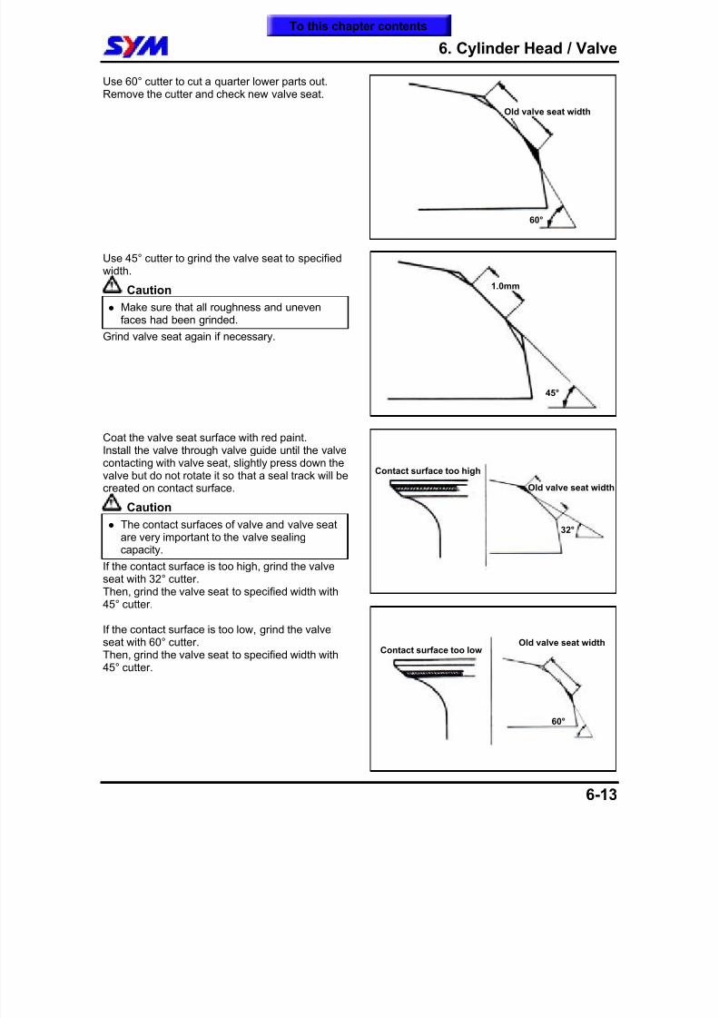
8/12/2019 SYM Mio50 Service Manual 000
http://slidepdf.com/reader/full/sym-mio50-service-manual-000 82/215
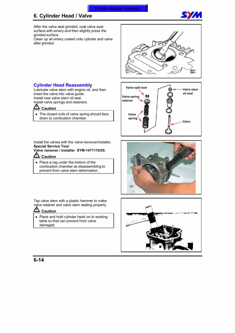
8/12/2019 SYM Mio50 Service Manual 000
http://slidepdf.com/reader/full/sym-mio50-service-manual-000 83/215
6. Cylinder Head / Valve
6-14
After the valve seat grinded, coat valve seatsurface with emery and then slightly press thegrinded surface.Clean up all emery coated onto cylinder and valveafter grinded.
Cylinder Head ReassemblyLubricate valve stem with engine oil, and theninsert the valve into valve guide.
Install new valve stem oil seal.Install valve springs and retainers.
Caution
The closed coils of valve spring should facedown to combustion chamber.
Install the valves with the valve remover/installer.
Special Service Tool:Valve remover / installer SYM-1471110/20.
Caution
Place a rag under the bottom of thecombustion chamber as disassembling toprevent from valve stem deformation.
Tap valve stem with a plastic hammer to makevalve retainer and valve stem sealing properly.
Caution
Place and hold cylinder head on to workingtable so that can prevent from valvedamaged.
Valve stem
oil seal
Valve
spring
Valve springretainer
Valve split lock
Valve
To this chapter contents
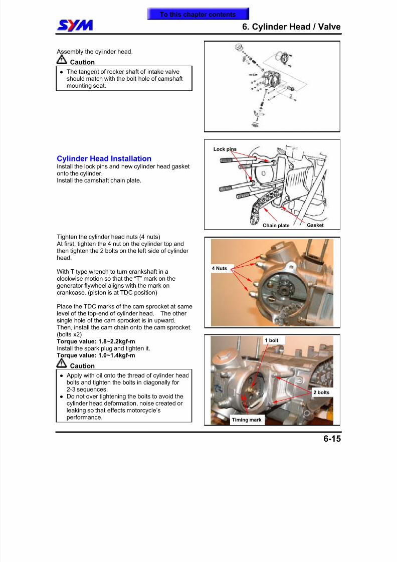
8/12/2019 SYM Mio50 Service Manual 000
http://slidepdf.com/reader/full/sym-mio50-service-manual-000 84/215
6. Cylinder Head / Valve
6-15
Assembly the cylinder head.
Caution
The tangent of rocker shaft of intake valve
should match with the bolt hole of camshaftmounting seat.
Cylinder Head InstallationInstall the lock pins and new cylinder head gasketonto the cylinder.Install the camshaft chain plate.
Tighten the cylinder head nuts (4 nuts)
At first, tighten the 4 nut on the cylinder top andthen tighten the 2 bolts on the left side of cylinderhead.
With T type wrench to turn crankshaft in aclockwise motion so that the “T” mark on thegenerator flywheel aligns with the mark oncrankcase. (piston is at TDC position)
Place the TDC marks of the cam sprocket at samelevel of the top-end of cylinder head. The othersingle hole of the cam sprocket is in upward.
Then, install the cam chain onto the cam sprocket.(bolts x2)Torque value: 1.8~2.2kgf-mInstall the spark plug and tighten it.Torque value: 1.0~1.4kgf-m
Caution
Apply with oil onto the thread of cylinder headbolts and tighten the bolts in diagonally for2-3 sequences.
Do not over tightening the bolts to avoid thecylinder head deformation, noise created or
leaking so that effects motorcycle’sperformance.
Chain plate
Lock pins
Gasket
4 Nuts
Timing mark
2 bolts
1 bolt
To this chapter contents
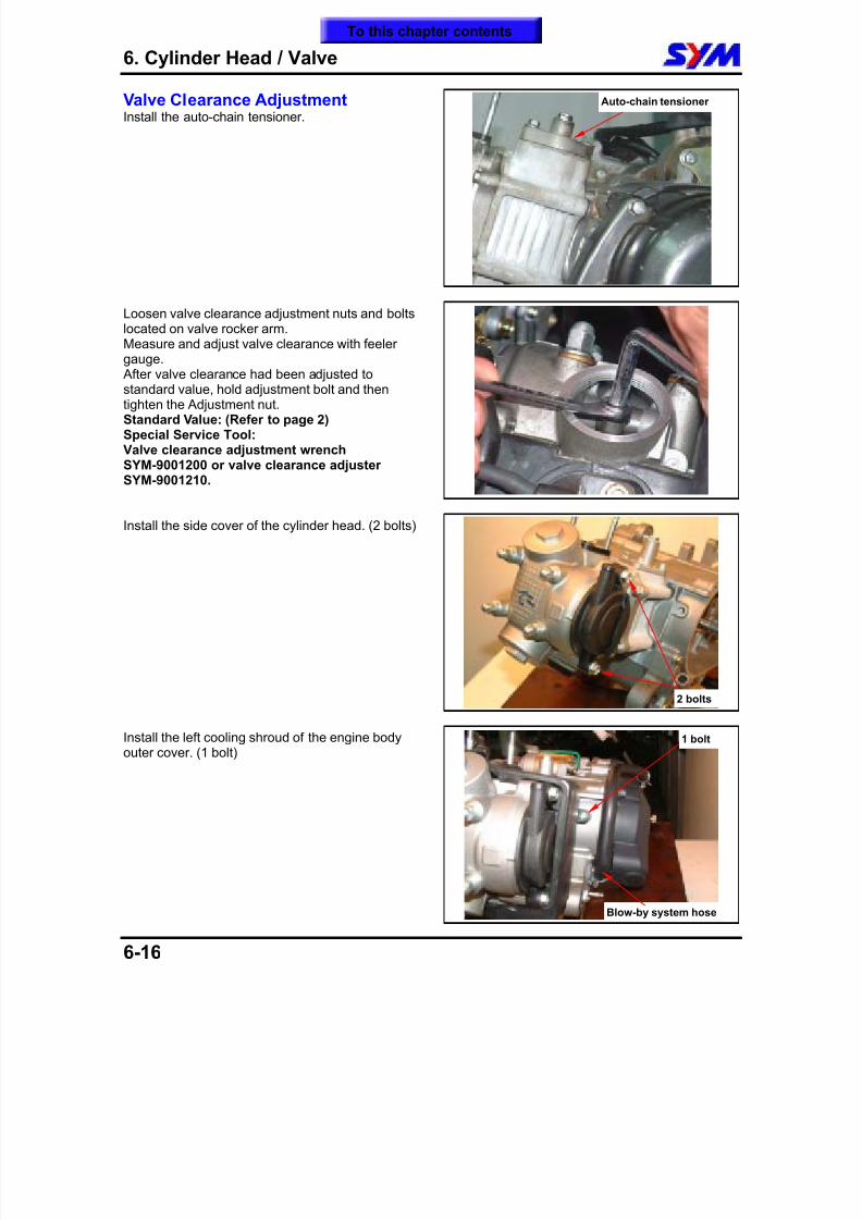
8/12/2019 SYM Mio50 Service Manual 000
http://slidepdf.com/reader/full/sym-mio50-service-manual-000 85/215
6. Cylinder Head / Valve
6-16
Valve Clearance AdjustmentInstall the auto-chain tensioner.
Loosen valve clearance adjustment nuts and boltslocated on valve rocker arm.Measure and adjust valve clearance with feeler
gauge. After valve clearance had been adjusted tostandard value, hold adjustment bolt and thentighten the Adjustment nut.Standard Value: (Refer to page 2)Special Service Tool:Valve clearance adjustment wrenchSYM-9001200 or valve clearance adjusterSYM-9001210.
Install the side cover of the cylinder head. (2 bolts)
Install the left cooling shroud of the engine bodyouter cover. (1 bolt)
Auto-chain tensioner
2 bolts
Blow-by system hose
1 bolt
To this chapter contents
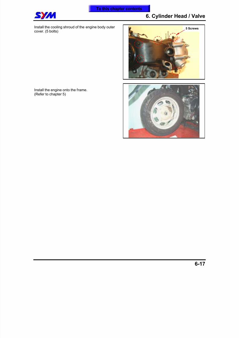
8/12/2019 SYM Mio50 Service Manual 000
http://slidepdf.com/reader/full/sym-mio50-service-manual-000 86/215

8/12/2019 SYM Mio50 Service Manual 000
http://slidepdf.com/reader/full/sym-mio50-service-manual-000 87/215
6. Cylinder Head / Valve
6-18
Notes:
To this chapter contents
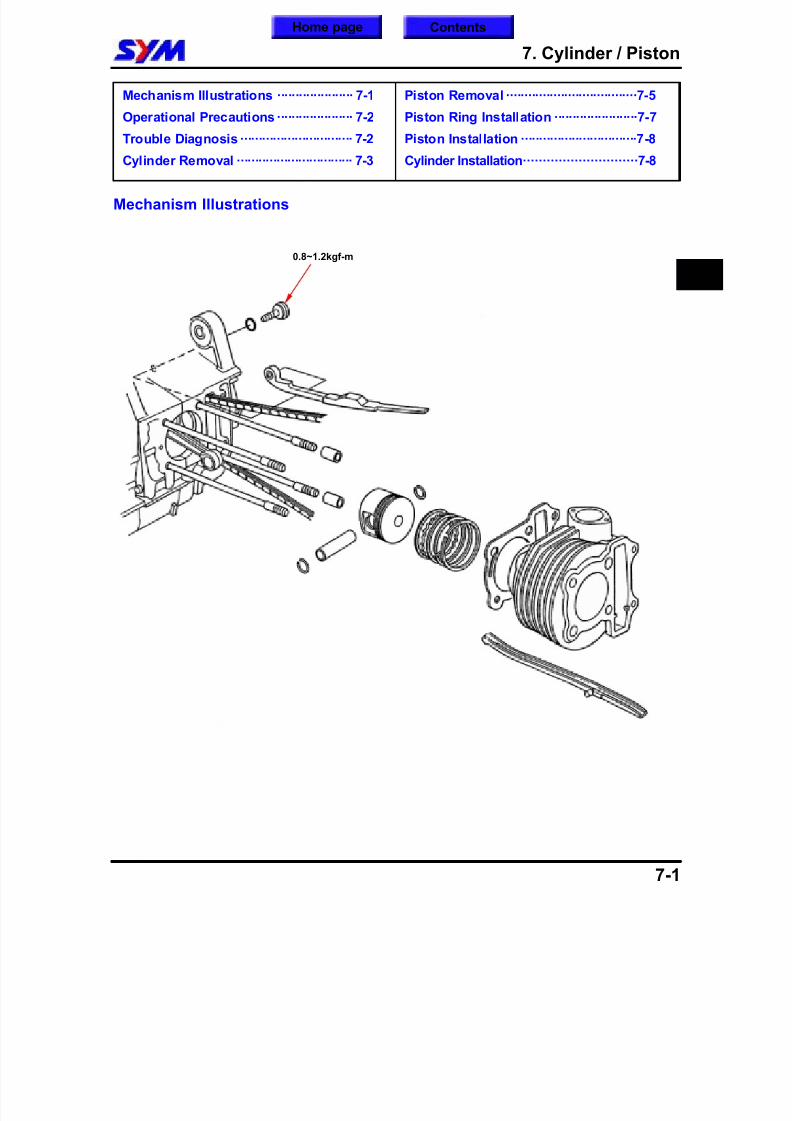
8/12/2019 SYM Mio50 Service Manual 000
http://slidepdf.com/reader/full/sym-mio50-service-manual-000 88/215
7. Cylinder / Piston
7-1
Mechanism Illustrations ····················· 7-1
Operational Precautions····················· 7-2
Trouble Diagnosis ······························· 7-2
Cylinder Removal ································ 7-3
Piston Removal ····································7-5
Piston Ring Installation ·······················7-7
Piston Installation ································7-8
Cylinder Installation·····························7-8
Mechanism Illustrations
7
0.8~1.2kgf-m
Home page Contents
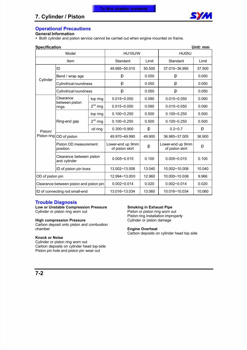
8/12/2019 SYM Mio50 Service Manual 000
http://slidepdf.com/reader/full/sym-mio50-service-manual-000 89/215
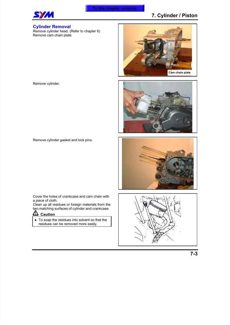
8/12/2019 SYM Mio50 Service Manual 000
http://slidepdf.com/reader/full/sym-mio50-service-manual-000 90/215
7. Cylinder / Piston
7-3
Cylinder RemovalRemove cylinder head. (Refer to chapter 6)Remove cam chain plate.
Remove cylinder.
Remove cylinder gasket and lock pins.
Cover the holes of crankcase and cam chain witha piece of cloth.Clean up all residues or foreign materials from thetwo matching surfaces of cylinder and crankcase.
Caution
To soap the residues into solvent so that theresidues can be removed more easily.
Cam chain plate
To this chapter contents
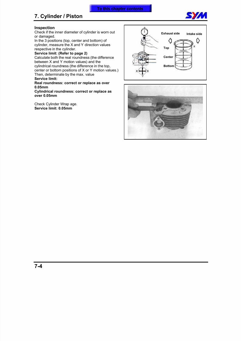
8/12/2019 SYM Mio50 Service Manual 000
http://slidepdf.com/reader/full/sym-mio50-service-manual-000 91/215
7. Cylinder / Piston
7-4
InspectionCheck if the inner diameter of cylinder is worn outor damaged.In the 3 positions (top, center and bottom) ofcylinder, measure the X and Y direction values
respective in the cylinder.Service limit: (Refer to page 2)Calculate both the real roundness (the differencebetween X and Y motion values) and thecylindrical roundness (the difference in the top,center or bottom positions of X or Y motion values.)Then, determinate by the max. valueService limit:Real roundness: correct or replace as over0.05mmCylindrical roundness: correct or replace asover 0.05mm
Check Cylinder Wrap age.Service limit: 0.05mm
Top
Center
Bottom
Exhaust side Intake side
To this chapter contents
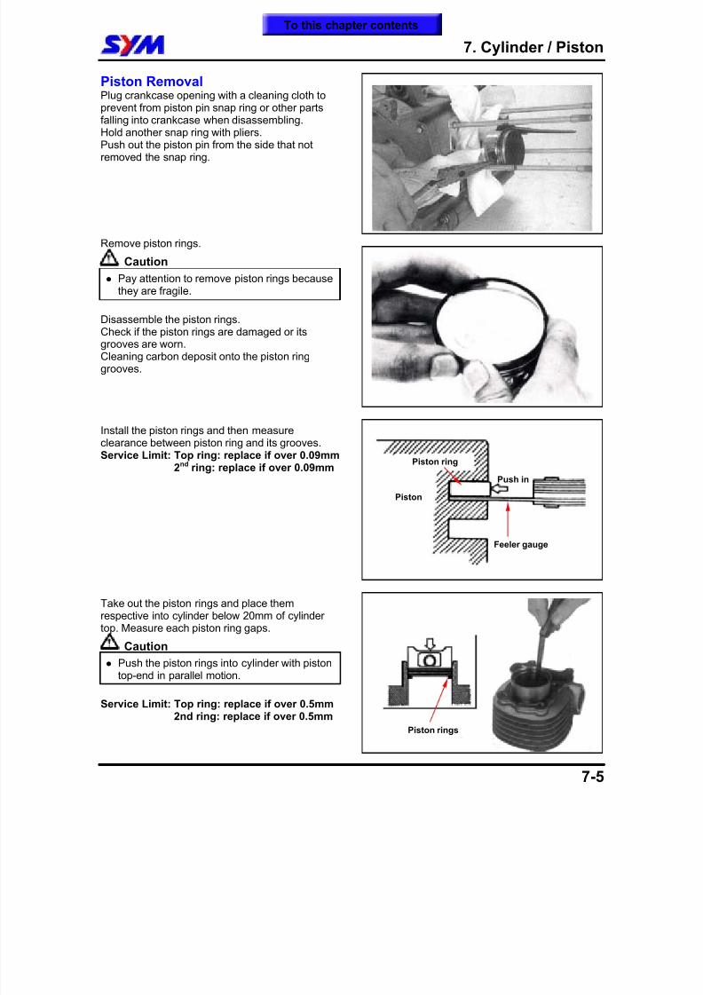
8/12/2019 SYM Mio50 Service Manual 000
http://slidepdf.com/reader/full/sym-mio50-service-manual-000 92/215
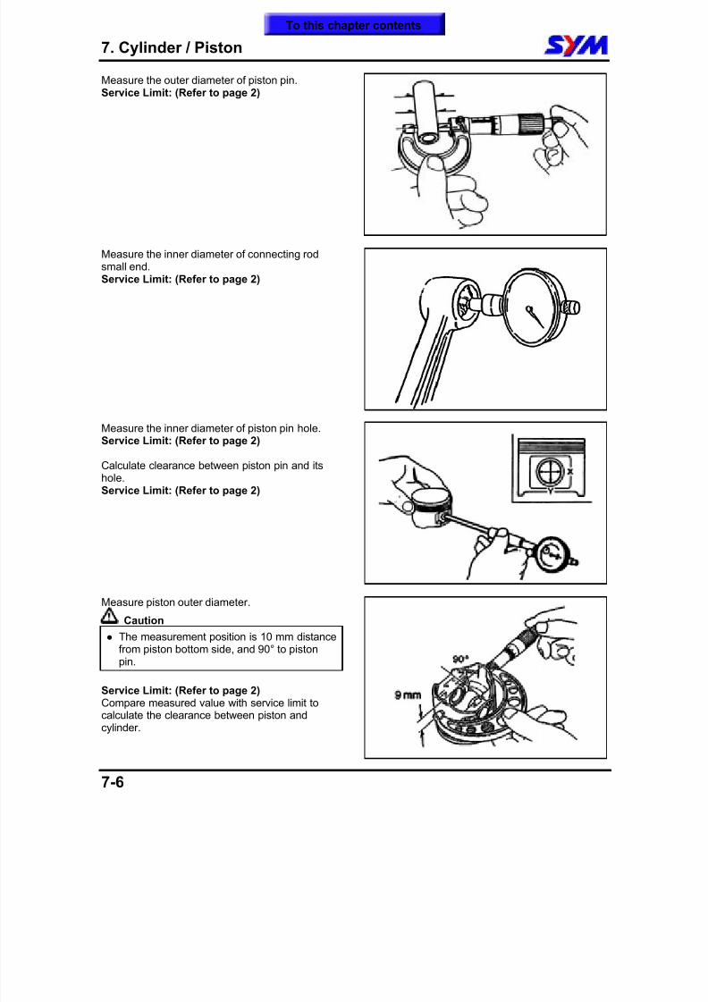
8/12/2019 SYM Mio50 Service Manual 000
http://slidepdf.com/reader/full/sym-mio50-service-manual-000 93/215
7. Cylinder / Piston
7-6
Measure the outer diameter of piston pin.Service Limit: (Refer to page 2)
Measure the inner diameter of connecting rodsmall end.Service Limit: (Refer to page 2)
Measure the inner diameter of piston pin hole.
Service Limit: (Refer to page 2)
Calculate clearance between piston pin and itshole.Service Limit: (Refer to page 2)
Measure piston outer diameter.
Caution
The measurement position is 10 mm distancefrom piston bottom side, and 90° to pistonpin.
Service Limit: (Refer to page 2)Compare measured value with service limit tocalculate the clearance between piston and
cylinder.
To this chapter contents
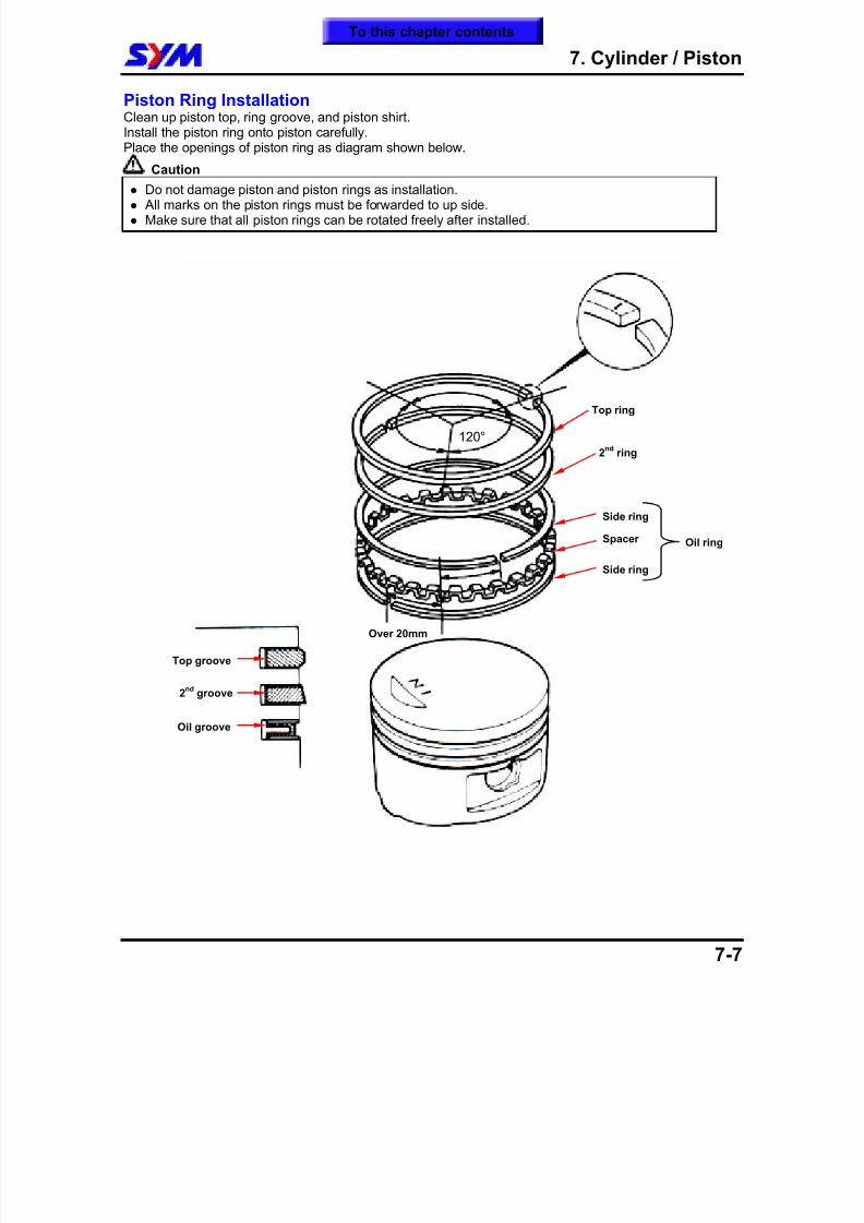
8/12/2019 SYM Mio50 Service Manual 000
http://slidepdf.com/reader/full/sym-mio50-service-manual-000 94/215
7. Cylinder / Piston
7-7
Piston Ring InstallationClean up piston top, ring groove, and piston shirt.Install the piston ring onto piston carefully.Place the openings of piston ring as diagram shown below.
Caution
Do not damage piston and piston rings as installation. All marks on the piston rings must be forwarded to up side. Make sure that all piston rings can be rotated freely after installed.
120°
Top groove
2nd
groove
Oil groove
Top ring
2nd
ring
Oil ringSpacer
Side ring
Side ring
Over 20mm
To this chapter contents
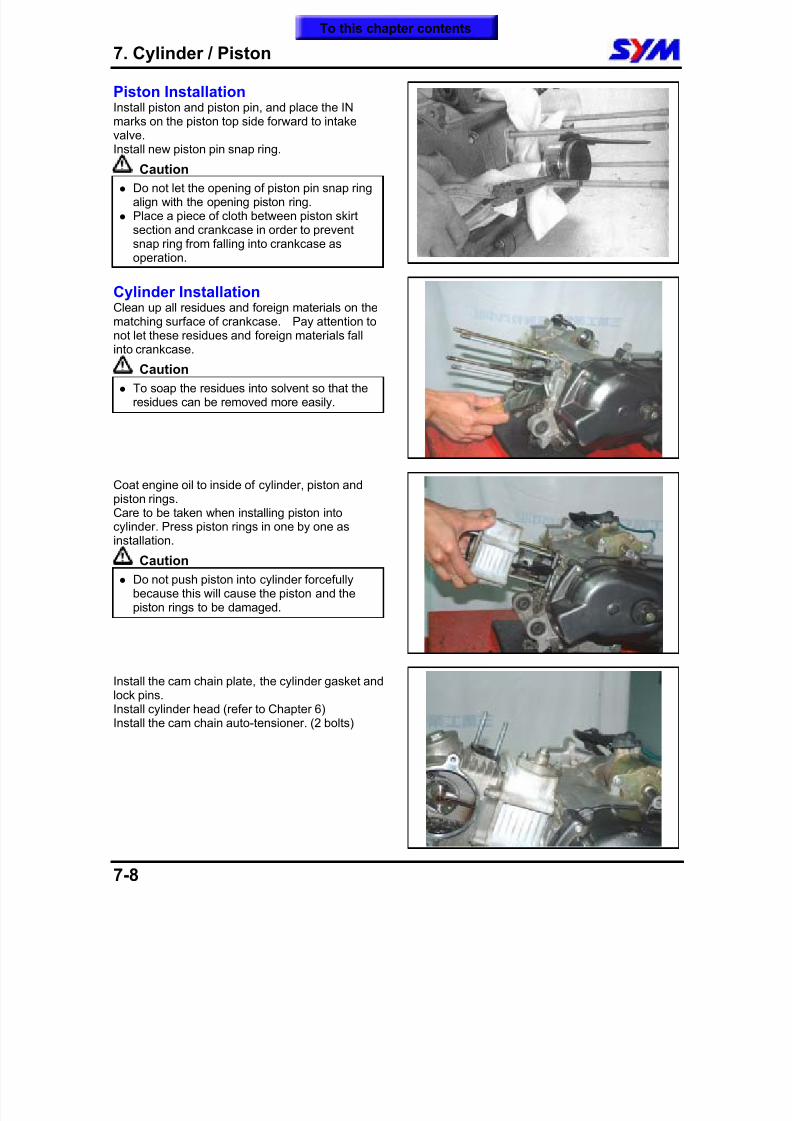
8/12/2019 SYM Mio50 Service Manual 000
http://slidepdf.com/reader/full/sym-mio50-service-manual-000 95/215
7. Cylinder / Piston
7-8
Piston InstallationInstall piston and piston pin, and place the INmarks on the piston top side forward to intakevalve.Install new piston pin snap ring.
Caution
Do not let the opening of piston pin snap ringalign with the opening piston ring.
Place a piece of cloth between piston skirtsection and crankcase in order to preventsnap ring from falling into crankcase asoperation.
Cylinder InstallationClean up all residues and foreign materials on the
matching surface of crankcase. Pay attention tonot let these residues and foreign materials fallinto crankcase.
Caution
To soap the residues into solvent so that theresidues can be removed more easily.
Coat engine oil to inside of cylinder, piston andpiston rings.Care to be taken when installing piston intocylinder. Press piston rings in one by one asinstallation.
Caution
Do not push piston into cylinder forcefullybecause this will cause the piston and thepiston rings to be damaged.
Install the cam chain plate, the cylinder gasket andlock pins.Install cylinder head (refer to Chapter 6)Install the cam chain auto-tensioner. (2 bolts)
To this chapter contents
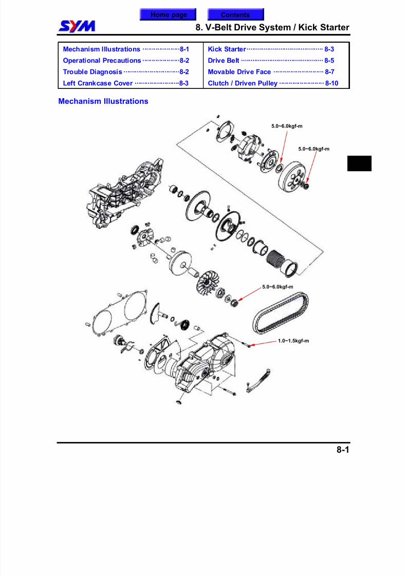
8/12/2019 SYM Mio50 Service Manual 000
http://slidepdf.com/reader/full/sym-mio50-service-manual-000 96/215
8. V-Belt Drive System / Kick Starter
8-1
Mechanism Illustrations ····················8-1
Operational Precautions····················8-2
Trouble Diagnosis ······························8-2
Left Crankcase Cover ························8-3
Kick Starter········································· 8-3
Drive Belt ············································ 8-5
Movable Drive Face ··························· 8-7
Clutch / Driven Pulley ························ 8-10
Mechanism Illustrations
8
5.0~6.0kgf-m
5.0~6.0kgf-m
5.0~6.0kgf-m
1.0~1.5kgf-m
Home page Contents
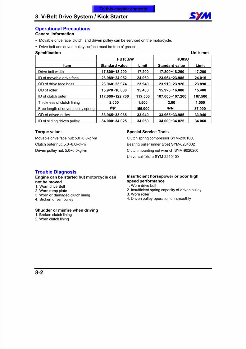
8/12/2019 SYM Mio50 Service Manual 000
http://slidepdf.com/reader/full/sym-mio50-service-manual-000 97/215
8. V-Belt Drive System / Kick Starter
8-2
Operational PrecautionsGeneral Information
Movable drive face, clutch, and driven pulley can be serviced on the motorcycle.
Drive belt and driven pulley surface must be free of grease.
Specification Unit: mm
HU10U/W HU05U
Item Standard value Limit Standard value Limit
Drive belt width 17.800~18.200 17.200 17.800~18.200 17.200
ID of movable drive face 23.989~24.052 24.060 23.964~23.985 24.015
OD of drive face boss 23.960~23.974 23.940 23.910~23.926 23.890
OD of roller 15.920~16.080 15.400 15.920~16.080 15.400
ID of clutch outer 112.000~122.200 112.500 107.000~107.200 107.500
Thickness of clutch lining 2.000 1.500 2.00 1.500
Free length of driven pulley spring ¢ ¢ 156.000 ¢w¢w
87.900
OD of driven pulley 33.965~33.985 33.940 33.965~33.985 33.940
ID of sliding driven pulley 34.000~34.025 34.060 34.000~34.025 34.060
Torque value:
Movable drive face nut: 5.0~6.0kgf-m
Clutch outer nut: 5.0~6.0kgf-m
Driven pulley nut: 5.0~6.0kgf-m
Special Service Tools
Clutch spring compressor SYM-2301000
Bearing puller (inner type) SYM-6204002
Clutch mounting nut wrench SYM-9020200Universal fixture SYM-2210100
Trouble DiagnosisEngine can be started but motorcycle cannot be moved1. Worn drive Belt2. Worn ramp plate3. Worn or damaged clutch lining4. Broken driven pulley
Shudder or misfire when driving1. Broken clutch lining2. Worn clutch lining
Insufficient horsepower or poor highspeed performance1. Worn drive belt2. Insufficient spring capacity of driven pulley3. Worn roller4. Driven pulley operation un-smoothly
To this chapter contents
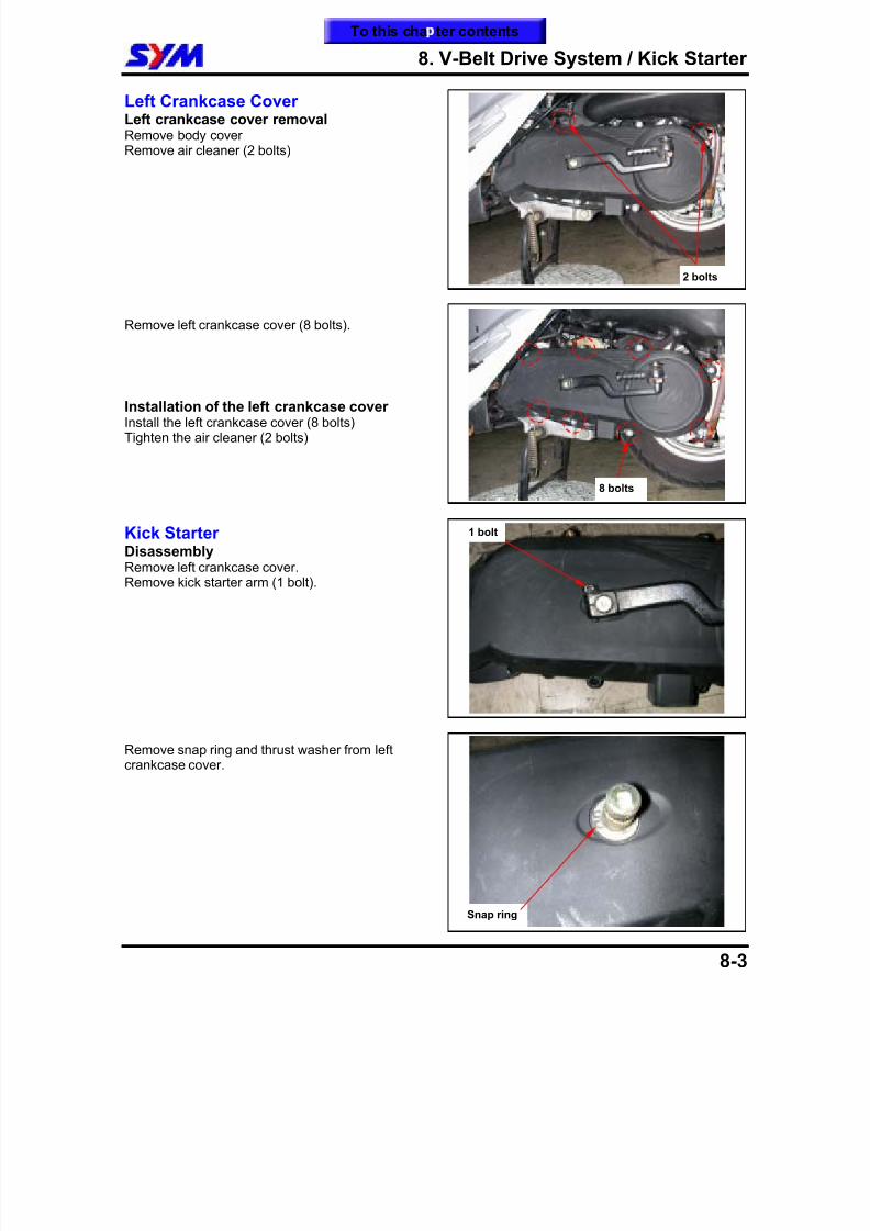
8/12/2019 SYM Mio50 Service Manual 000
http://slidepdf.com/reader/full/sym-mio50-service-manual-000 98/215
8. V-Belt Drive System / Kick Starter
8-3
Left Crankcase CoverLeft crankcase cover removalRemove body coverRemove air cleaner (2 bolts)
Remove left crankcase cover (8 bolts).
Installation of the left crankcase coverInstall the left crankcase cover (8 bolts)Tighten the air cleaner (2 bolts)
Kick StarterDisassemblyRemove left crankcase cover.Remove kick starter arm (1 bolt).
Remove snap ring and thrust washer from leftcrankcase cover.
2 bolts
8 bolts
Snap ring
1 bolt
To this cha ter contents
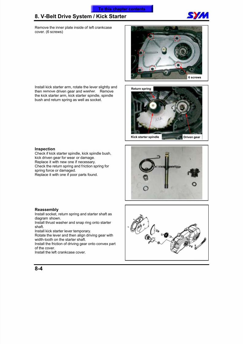
8/12/2019 SYM Mio50 Service Manual 000
http://slidepdf.com/reader/full/sym-mio50-service-manual-000 99/215
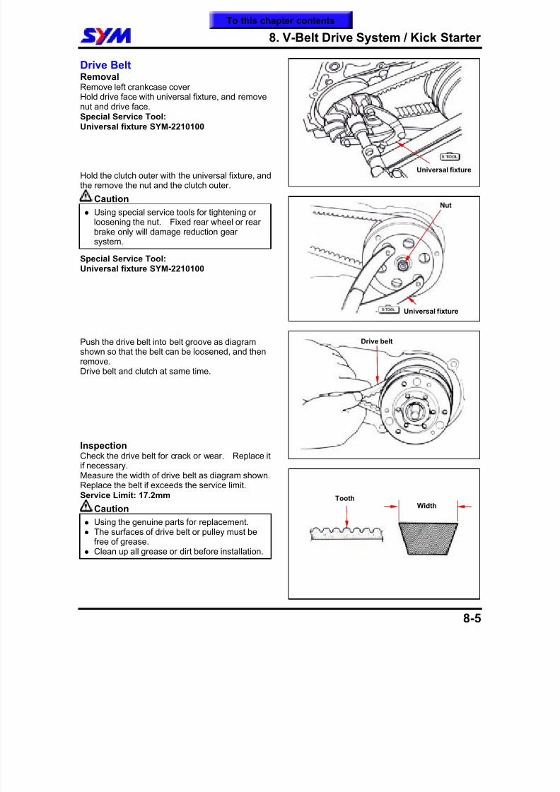
8/12/2019 SYM Mio50 Service Manual 000
http://slidepdf.com/reader/full/sym-mio50-service-manual-000 100/215
8. V-Belt Drive System / Kick Starter
8-5
Drive BeltRemoval Remove left crankcase coverHold drive face with universal fixture, and removenut and drive face.
Special Service Tool:Universal fixture SYM-2210100
Hold the clutch outer with the universal fixture, andthe remove the nut and the clutch outer.
Caution
Using special service tools for tightening orloosening the nut. Fixed rear wheel or rear
brake only will damage reduction gearsystem.
Special Service Tool:Universal fixture SYM-2210100
Push the drive belt into belt groove as diagramshown so that the belt can be loosened, and thenremove.Drive belt and clutch at same time.
InspectionCheck the drive belt for crack or wear. Replace itif necessary.Measure the width of drive belt as diagram shown.Replace the belt if exceeds the service limit.Service Limit: 17.2mm
Caution
Using the genuine parts for replacement. The surfaces of drive belt or pulley must be
free of grease. Clean up all grease or dirt before installation.
Universal fixture
ToothWidth
Nut
Drive belt
Universal fixture
To this chapter contents
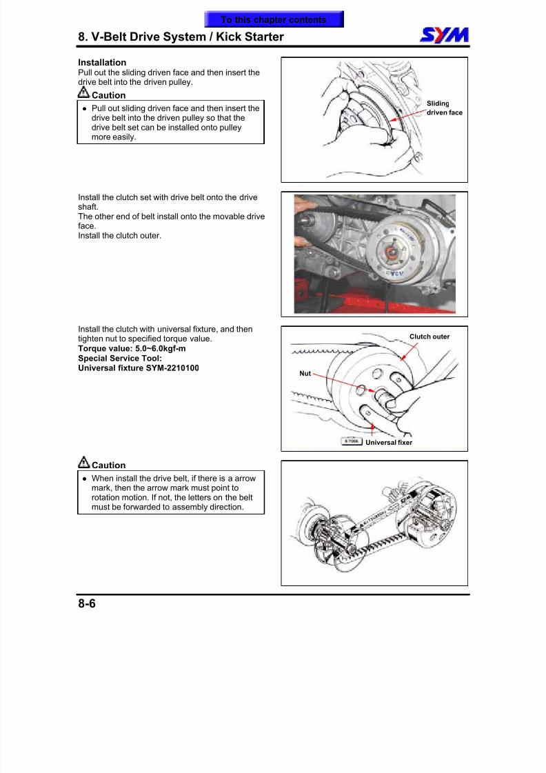
8/12/2019 SYM Mio50 Service Manual 000
http://slidepdf.com/reader/full/sym-mio50-service-manual-000 101/215
8. V-Belt Drive System / Kick Starter
8-6
InstallationPull out the sliding driven face and then insert thedrive belt into the driven pulley.
Caution
Pull out sliding driven face and then insert thedrive belt into the driven pulley so that thedrive belt set can be installed onto pulleymore easily.
Install the clutch set with drive belt onto the driveshaft.The other end of belt install onto the movable drive
face.Install the clutch outer.
Install the clutch with universal fixture, and then
tighten nut to specified torque value.Torque value: 5.0~6.0kgf-mSpecial Service Tool:Universal fixture SYM-2210100
Caution
When install the drive belt, if there is a arrowmark, then the arrow mark must point torotation motion. If not, the letters on the beltmust be forwarded to assembly direction.
Sliding
driven face
Universal fixer
Nut
Clutch outer
To this chapter contents
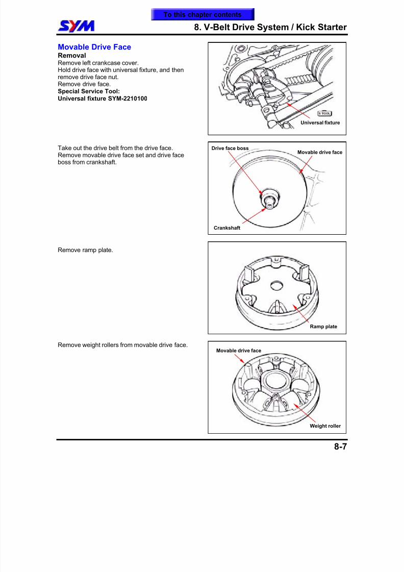
8/12/2019 SYM Mio50 Service Manual 000
http://slidepdf.com/reader/full/sym-mio50-service-manual-000 102/215
8. V-Belt Drive System / Kick Starter
8-7
Movable Drive FaceRemovalRemove left crankcase cover.Hold drive face with universal fixture, and thenremove drive face nut.
Remove drive face.Special Service Tool:Universal fixture SYM-2210100
Take out the drive belt from the drive face.Remove movable drive face set and drive faceboss from crankshaft.
Remove ramp plate.
Remove weight rollers from movable drive face. Movable drive face
Weight roller
Movable drive faceDrive face boss
Ramp plate
Crankshaft
Universal fixture
To this chapter contents
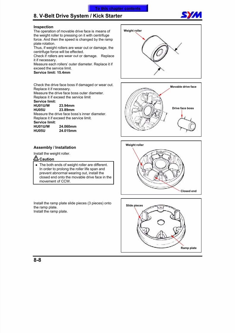
8/12/2019 SYM Mio50 Service Manual 000
http://slidepdf.com/reader/full/sym-mio50-service-manual-000 103/215
8. V-Belt Drive System / Kick Starter
8-8
InspectionThe operation of movable drive face is means ofthe weight roller to pressing on it with centrifugeforce. And then the speed is changed by the rampplate rotation.
Thus, if weight rollers are wear out or damage, thecentrifuge force will be effected.Check if rollers are wear out or damage. Replaceit if necessary.Measure each rollers’ outer diameter. Replace it ifexceed the service limit.Service limit: 15.4mm
Check the drive face boss if damaged or wear out.Replace it if necessary.Measure the drive face boss outer diameter.
Replace it if exceed the service limitService limit:HU01U/W 23.94mmHU05U 23.89mmMeasure the drive face boss’s inner diameter.Replace it if exceed the service limit.Service limit:HU01U/W 24.060mmHU05U 24.015mm
Assembly / Installation
Install the weight roller.
Caution
The both ends of weight roller are different.In order to prolong the roller life span andprevent abnormal wearing out, install theclosed end onto the movable drive face in themovement of CCW.
Install the ramp plate slide pieces (3 pieces) ontothe ramp plate.Install the ramp plate.
Weight roller
Slide pieces
Ramp plate
Movable drive face
Drive face boss
Closed end
Weight roller
To this chapter contents
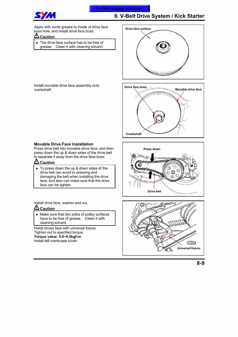
8/12/2019 SYM Mio50 Service Manual 000
http://slidepdf.com/reader/full/sym-mio50-service-manual-000 104/215
8. V-Belt Drive System / Kick Starter
8-9
Apply with some grease to inside of drive faceboss hole, and install drive face boss.
Caution
The drive face surface has to be free ofgrease. Clean it with cleaning solvent.
Install movable drive face assembly ontocrankshaft.
Movable Drive Face InstallationPress drive belt into movable drive face, and thenpress down the up & down sides of the drive beltto separate it away from the drive face boss.
Caution
To press down the up & down sides of thedrive belt can avoid to pressing anddamaging the belt when installing the driveface, and also can make sure that the driveface can be tighten.
Install drive face, washer and nut.
Caution
Make sure that two sides of pulley surfaceshave to be free of grease. Clean it withcleaning solvent.
Holds drives face with universal fixture.Tighten nut to specified torque.Torque value: 5.0~6.0kgf-mInstall left crankcase cover.
Drive face surface
Drive belt
Press down
Movable drive faceDrive face boss
Crankshaft
Universal fixture
To this chapter contents
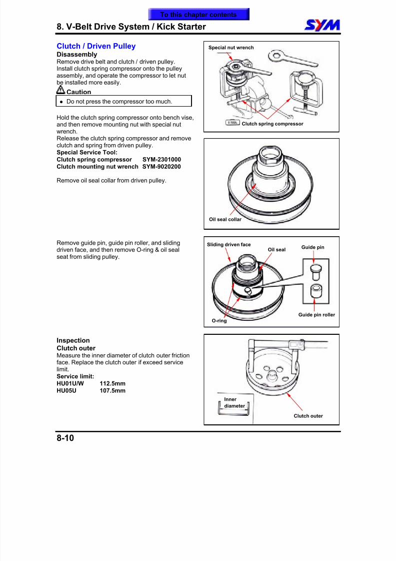
8/12/2019 SYM Mio50 Service Manual 000
http://slidepdf.com/reader/full/sym-mio50-service-manual-000 105/215
8. V-Belt Drive System / Kick Starter
8-10
Clutch / Driven PulleyDisassemblyRemove drive belt and clutch / driven pulley.Install clutch spring compressor onto the pulleyassembly, and operate the compressor to let nut
be installed more easily.
Caution
Do not press the compressor too much.
Hold the clutch spring compressor onto bench vise,and then remove mounting nut with special nutwrench.Release the clutch spring compressor and removeclutch and spring from driven pulley.Special Service Tool:Clutch spring compressor SYM-2301000Clutch mounting nut wrench SYM-9020200
Remove oil seal collar from driven pulley.
Remove guide pin, guide pin roller, and slidingdriven face, and then remove O-ring & oil sealseat from sliding pulley.
InspectionClutch outerMeasure the inner diameter of clutch outer frictionface. Replace the clutch outer if exceed servicelimit.Service limit:HU01U/W 112.5mmHU05U 107.5mm
Special nut wrench
Guide pin roller
Guide pinOil seal
Sliding driven face
Oil seal collar
Clutch spring compressor
O-ring
Clutch outer
Inner
diameter
To this chapter contents
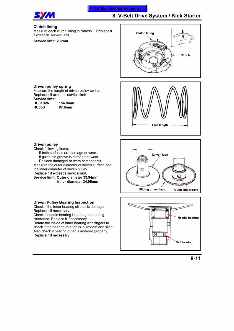
8/12/2019 SYM Mio50 Service Manual 000
http://slidepdf.com/reader/full/sym-mio50-service-manual-000 106/215
8. V-Belt Drive System / Kick Starter
8-11
Clutch liningMeasure each clutch lining thickness. Replace itif exceeds service limit.
Service limit: 2.0mm
Driven pulley springMeasure the length of driven pulley spring.
Replace it if exceeds service limitService limit:HU01U/W 156.0mmHU05U 87.9mm
Driven pulleyCheck following items: If both surfaces are damage or wear. If guide pin groove is damage or wear. Replace damaged or worn components.Measure the outer diameter of driven surface andthe inner diameter of driven pulley.Replace it if exceeds service limit.Service limit: Outer diameter 33.94mm
Inner diameter 34.06mm
Driven Pulley Bearing InspectionCheck if the inner bearing oil seal is damage.Replace it if necessary.Check if needle bearing is damage or too bigclearance. Replace it if necessary.Rotate the inside of inner bearing with fingers tocheck if the bearing rotation is in smooth and silent. Also check if bearing outer is installed properly.Replace it if necessary.
Guide pin groove
Driven face
Free length
Sliding driven face
Clutch
Clutch lining
Needle bearing
Ball bearing
To this chapter contents
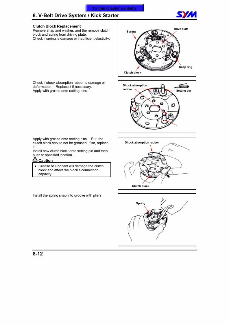
8/12/2019 SYM Mio50 Service Manual 000
http://slidepdf.com/reader/full/sym-mio50-service-manual-000 107/215
8. V-Belt Drive System / Kick Starter
8-12
Clutch Block ReplacementRemove snap and washer, and the remove clutchblock and spring from driving plate.Check if spring is damage or insufficient elasticity.
Check if shock absorption rubber is damage ordeformation. Replace it if necessary. Apply with grease onto setting pins.
Apply with grease onto setting pins. But, the
clutch block should not be greased. If so, replaceit.Install new clutch block onto setting pin and thenpush to specified location.
Caution
Grease or lubricant will damage the clutchblock and affect the block’s connectioncapacity.
Install the spring snap into groove with pliers.
Clutch block
Shock absorption rubber
Snap ring
Spring
Spring
Drive plate
Clutch block
Setting pin
Shock absorption
rubber
To this chapter contents
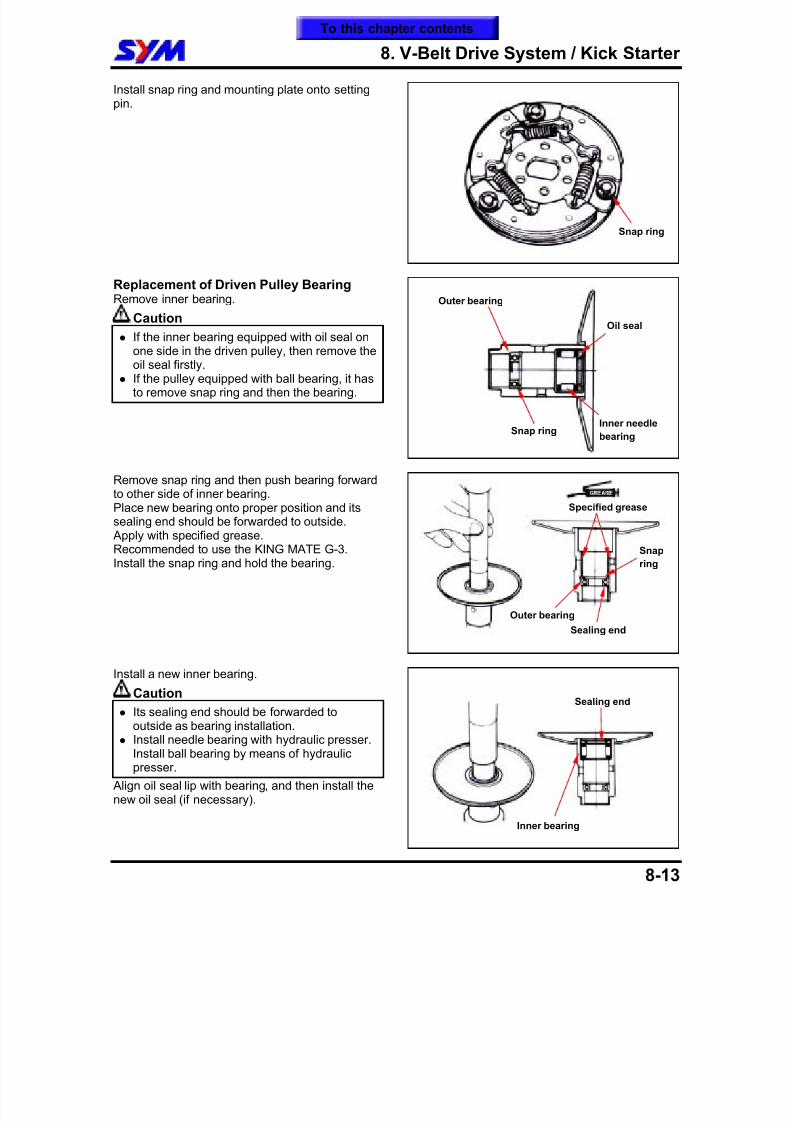
8/12/2019 SYM Mio50 Service Manual 000
http://slidepdf.com/reader/full/sym-mio50-service-manual-000 108/215
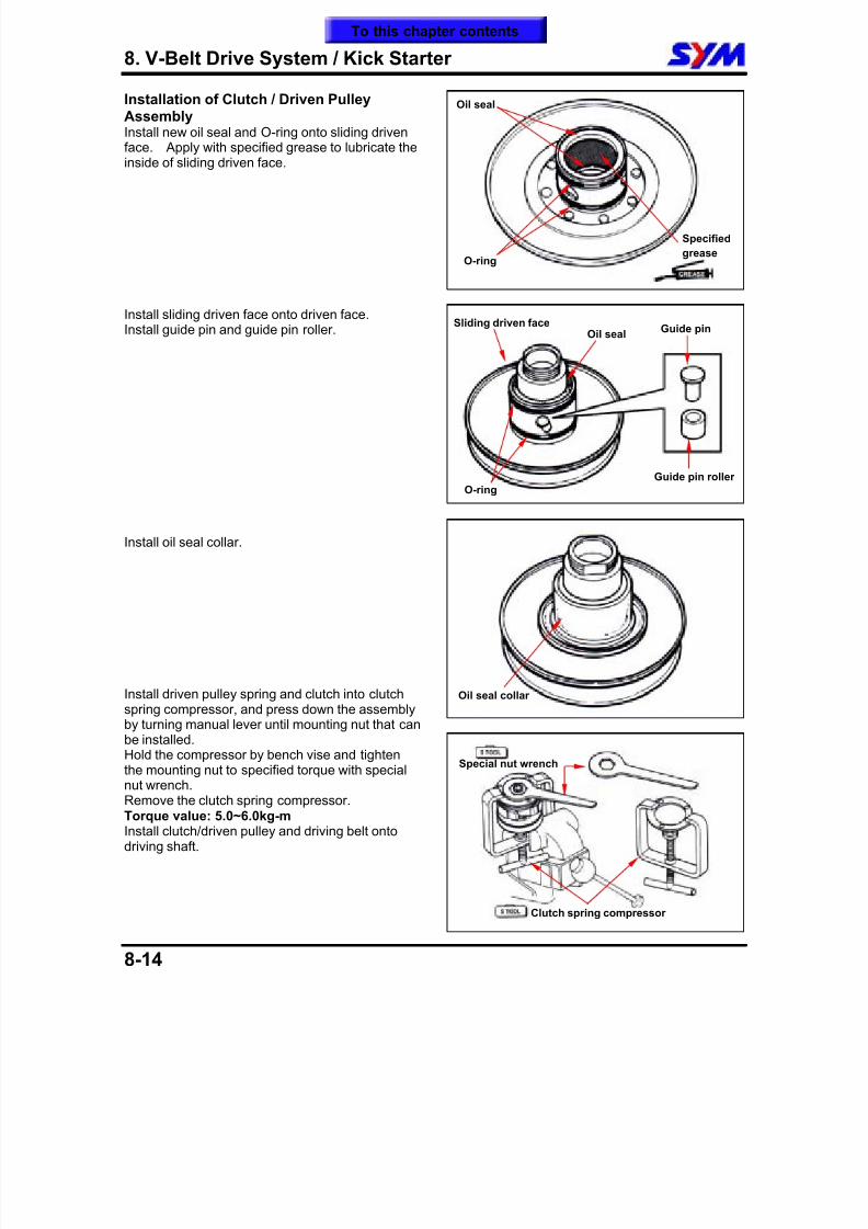
8/12/2019 SYM Mio50 Service Manual 000
http://slidepdf.com/reader/full/sym-mio50-service-manual-000 109/215
8. V-Belt Drive System / Kick Starter
8-14
Installation of Clutch / Driven PulleyAssemblyInstall new oil seal and O-ring onto sliding drivenface. Apply with specified grease to lubricate theinside of sliding driven face.
Install sliding driven face onto driven face.Install guide pin and guide pin roller.
Install oil seal collar.
Install driven pulley spring and clutch into clutch
spring compressor, and press down the assemblyby turning manual lever until mounting nut that canbe installed.Hold the compressor by bench vise and tightenthe mounting nut to specified torque with specialnut wrench.Remove the clutch spring compressor.Torque value: 5.0~6.0kg-mInstall clutch/driven pulley and driving belt ontodriving shaft.
Oil seal
O-ring
Specified
grease
Guide pin roller
Guide pinOil seal
Sliding driven face
O-ring
Special nut wrench
Clutch spring compressor
Oil seal collar
To this chapter contents
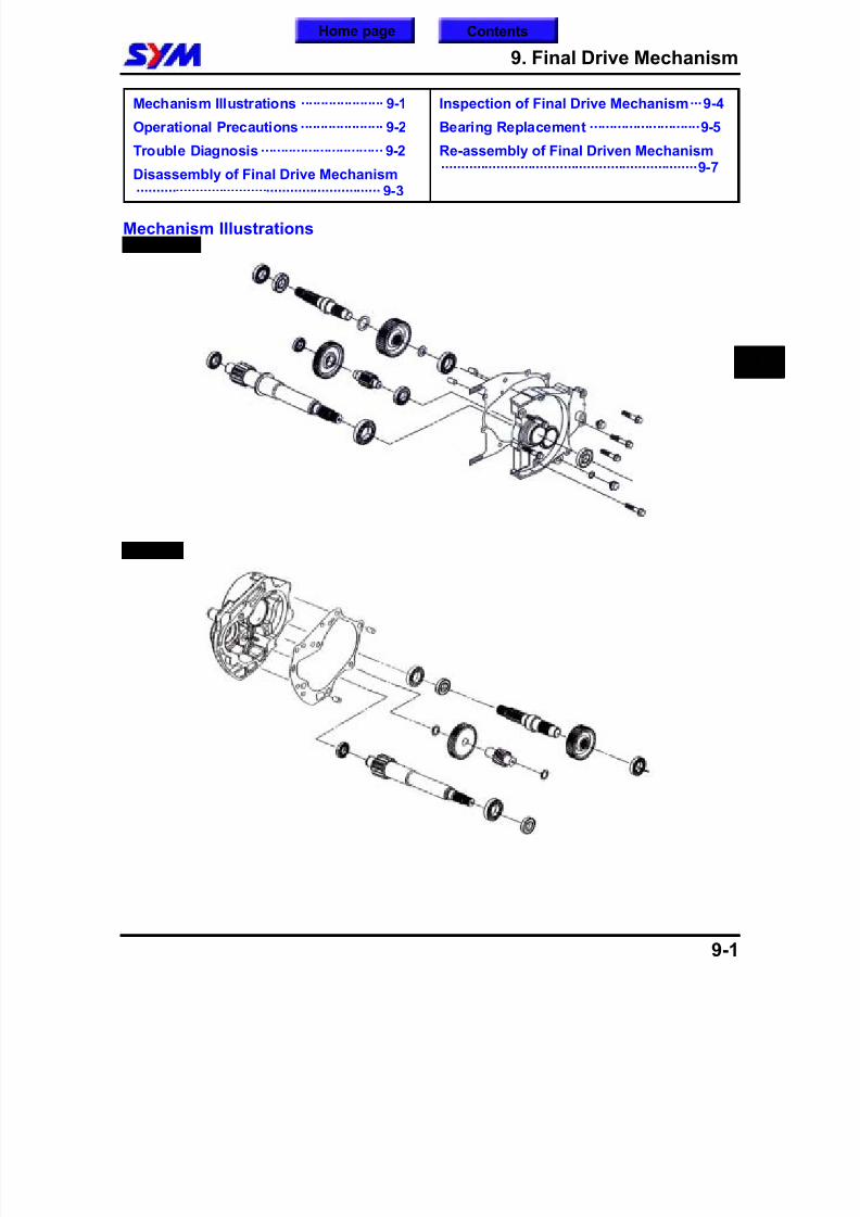
8/12/2019 SYM Mio50 Service Manual 000
http://slidepdf.com/reader/full/sym-mio50-service-manual-000 110/215
9. Final Drive Mechanism
9-1
Mechanism Illustrations ····················· 9-1
Operational Precautions····················· 9-2
Trouble Diagnosis ······························· 9-2
Disassembly of Final Drive Mechanism······························································ 9-3
Inspection of Final Drive Mechanism···9-4
Bearing Replacement ····························9-5
Re-assembly of Final Driven Mechanism·································································9-7
Mechanism Illustrations HU10U/W
HU05U
9
ContentsHome page
8/12/2019 SYM Mio50 Service Manual 000
http://slidepdf.com/reader/full/sym-mio50-service-manual-000 111/215
9. Final Drive Mechanism
9-2
Operational PrecautionsSpecification Application gear oil: GEAR OIL SAE 85W-140Recommended oil: KING MATE serial gear oilsOil quantity:
HU10U/W 110 c.c. (100 c.c. when replacing)HU05U 100 c.c. (90 c.c. when replacing)
Torque valueGear box cover 2.0~2.4kgf-mGear oil drain plug 1.0~1.4kgf-mGear oil filling bolt 0.8~1.2kgf-m
Special service toolsInner type bearing puller SYM-6204002Outer type bearing puller SYM-6204001
Gear box oil seal installer SYM-9120200Gear box bearing installer SYM-9125500Bearing (6204) installer SYM-9110400Bearing (6301) installer SYM-9610000Bearing (6203/6004UZ) installer SYM-9620000Drive shaft puller SYM-13000Puller set SYM-13000-01
Trouble DiagnosisEngine can be started but motorcycle can not be moved. Damaged drive gear. Burnt out drive gear. Broken drive belt.
Noise Worn or burnt gear. Worn gear.
Gear oil leaks Excessive gear oil. Worn or damage oil seal.
To this chapter contents
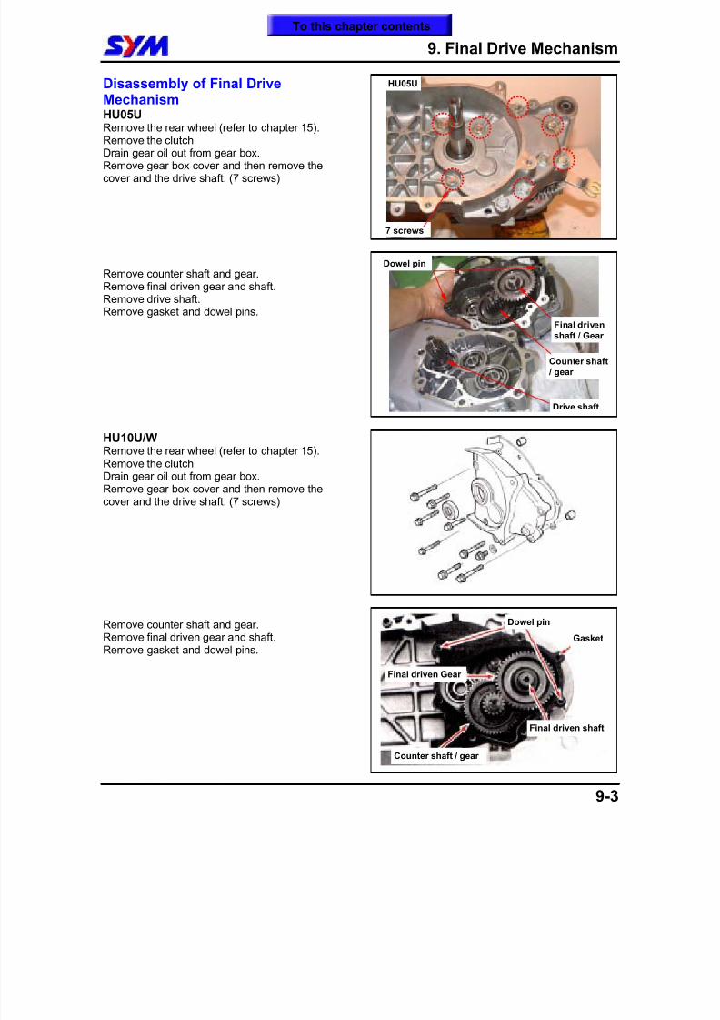
8/12/2019 SYM Mio50 Service Manual 000
http://slidepdf.com/reader/full/sym-mio50-service-manual-000 112/215
9. Final Drive Mechanism
9-3
Disassembly of Final DriveMechanismHU05URemove the rear wheel (refer to chapter 15).Remove the clutch.Drain gear oil out from gear box.Remove gear box cover and then remove thecover and the drive shaft. (7 screws)
Remove counter shaft and gear.Remove final driven gear and shaft.
Remove drive shaft.Remove gasket and dowel pins.
HU10U/WRemove the rear wheel (refer to chapter 15).Remove the clutch.Drain gear oil out from gear box.Remove gear box cover and then remove thecover and the drive shaft. (7 screws)
Remove counter shaft and gear.Remove final driven gear and shaft.Remove gasket and dowel pins.
7 screws
HU05U
Final drivenshaft / Gear
Counter shaft / gear
Dowel pin
Drive shaft
Final driven shaft
Counter shaft / gear
Dowel pin
Gasket
Final driven Gear
To this chapter contents
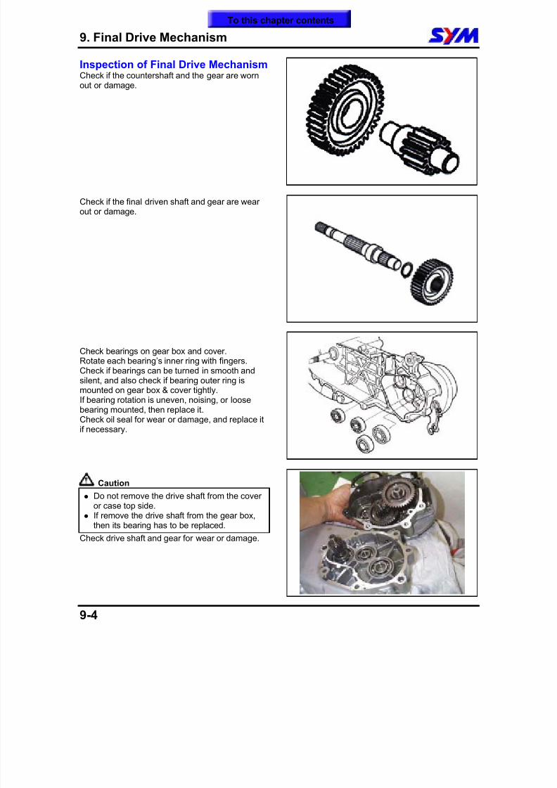
8/12/2019 SYM Mio50 Service Manual 000
http://slidepdf.com/reader/full/sym-mio50-service-manual-000 113/215
9. Final Drive Mechanism
9-4
Inspection of Final Drive MechanismCheck if the countershaft and the gear are wornout or damage.
Check if the final driven shaft and gear are wearout or damage.
Check bearings on gear box and cover.Rotate each bearing’s inner ring with fingers.Check if bearings can be turned in smooth andsilent, and also check if bearing outer ring ismounted on gear box & cover tightly.If bearing rotation is uneven, noising, or loosebearing mounted, then replace it.Check oil seal for wear or damage, and replace itif necessary.
Caution
Do not remove the drive shaft from the coveror case top side.
If remove the drive shaft from the gear box,then its bearing has to be replaced.
Check drive shaft and gear for wear or damage.
To this chapter contents
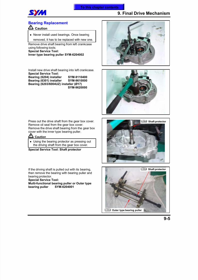
8/12/2019 SYM Mio50 Service Manual 000
http://slidepdf.com/reader/full/sym-mio50-service-manual-000 114/215
9. Final Drive Mechanism
9-5
Bearing Replacement
Caution
Never install used bearings. Once bearing
removed, it has to be replaced with new one. Remove drive shaft bearing from left crankcaseusing following tools;Special Service Tool:Inner type bearing puller SYM-6204002
Install new drive shaft bearing into left crankcase.Special Service Tool:Bearing (6204) installer SYM-9110400
Bearing (6301) installer SYM-9610000Bearing (6203/6004UZ) installer (Ø17)SYM-9620000
Press out the drive shaft from the gear box cover.Remove oil seal from the gear box cover.Remove the drive shaft bearing from the gear boxcover with the inner type bearing puller.
Caution
Using the bearing protector as pressing outthe driving shaft from the gear box cover.
Special Service Tool: Shaft protector
If the driving shaft is pulled out with its bearing,then remove the bearing with bearing puller andbearing protector.Special Service Tool:Multi-functional bearing puller or Outer typebearing puller SYM-6204001
Shaft protector
Outer type bearing puller
Shaft protector
To this chapter contents
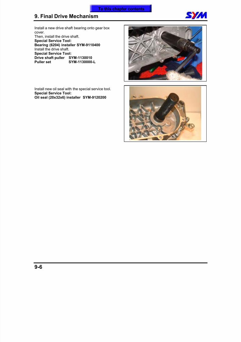
8/12/2019 SYM Mio50 Service Manual 000
http://slidepdf.com/reader/full/sym-mio50-service-manual-000 115/215
9. Final Drive Mechanism
9-6
Install a new drive shaft bearing onto gear boxcover.Then, install the drive shaft.Special Service Tool:Bearing (6204) installer SYM-9110400
Install the drive shaft.Special Service Tool:Drive shaft puller SYM-1130010Puller set SYM-1130000-L
Install new oil seal with the special service tool.Special Service Tool:Oil seal (20x32x6) installer SYM-9120200
To this chapter contents
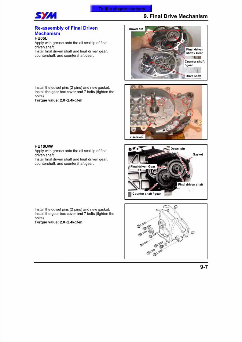
8/12/2019 SYM Mio50 Service Manual 000
http://slidepdf.com/reader/full/sym-mio50-service-manual-000 116/215
9. Final Drive Mechanism
9-7
Re-assembly of Final DrivenMechanismHU05U Apply with grease onto the oil seal lip of finaldriven shaft.Install final driven shaft and final driven gear,countershaft, and countershaft gear.
Install the dowel pins (2 pins) and new gasket.Install the gear box cover and 7 bolts (tighten thebolts).
Torque value: 2.0~2.4kgf-m
HU10U/W Apply with grease onto the oil seal lip of finaldriven shaft.Install final driven shaft and final driven gear,countershaft, and countershaft gear.
Install the dowel pins (2 pins) and new gasket.Install the gear box cover and 7 bolts (tighten thebolts).Torque value: 2.0~2.4kgf-m
Final drivenshaft / Gear
Counter shaft / gear
Dowel pin
Drive shaft
7 screws
Final driven shaft
Counter shaft / gear
Dowel pin
Gasket
Final driven Gear
To this chapter contents
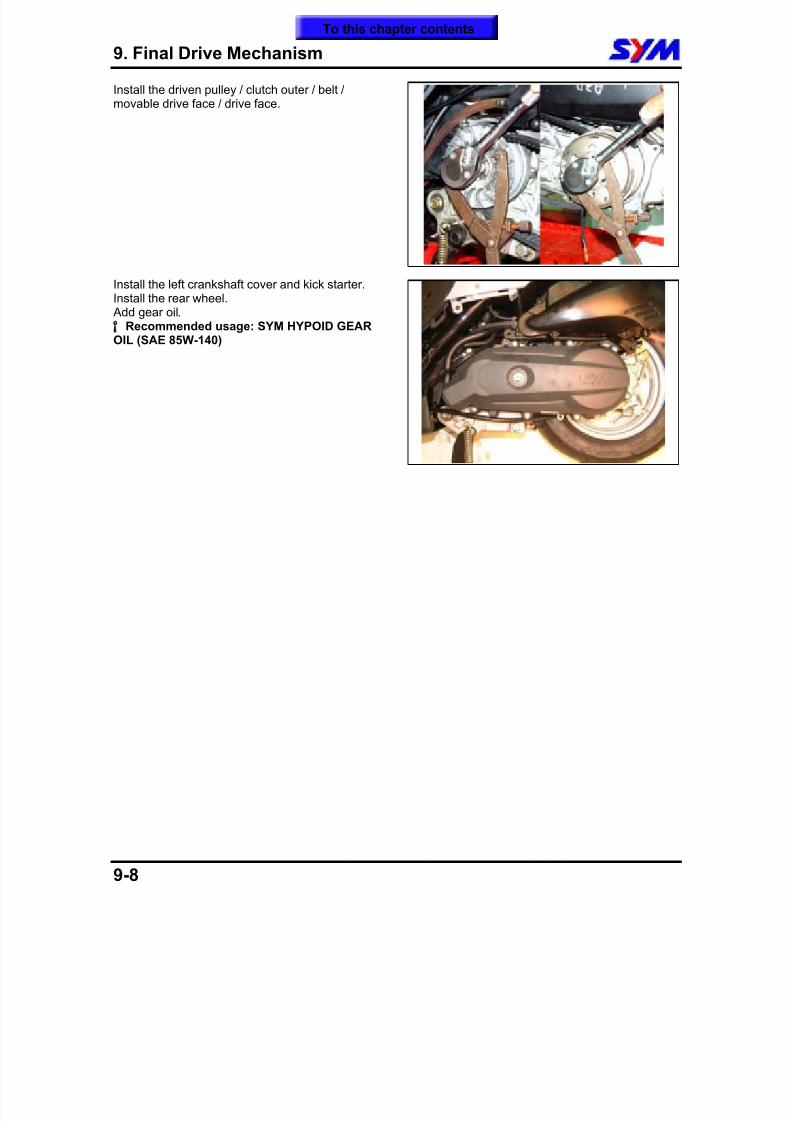
8/12/2019 SYM Mio50 Service Manual 000
http://slidepdf.com/reader/full/sym-mio50-service-manual-000 117/215
9. Final Drive Mechanism
9-8
Install the driven pulley / clutch outer / belt /movable drive face / drive face.
Install the left crankshaft cover and kick starter.Install the rear wheel. Add gear oil.
Recommended usage: SYM HYPOID GEAR°
OIL (SAE 85W-140)
To this chapter contents
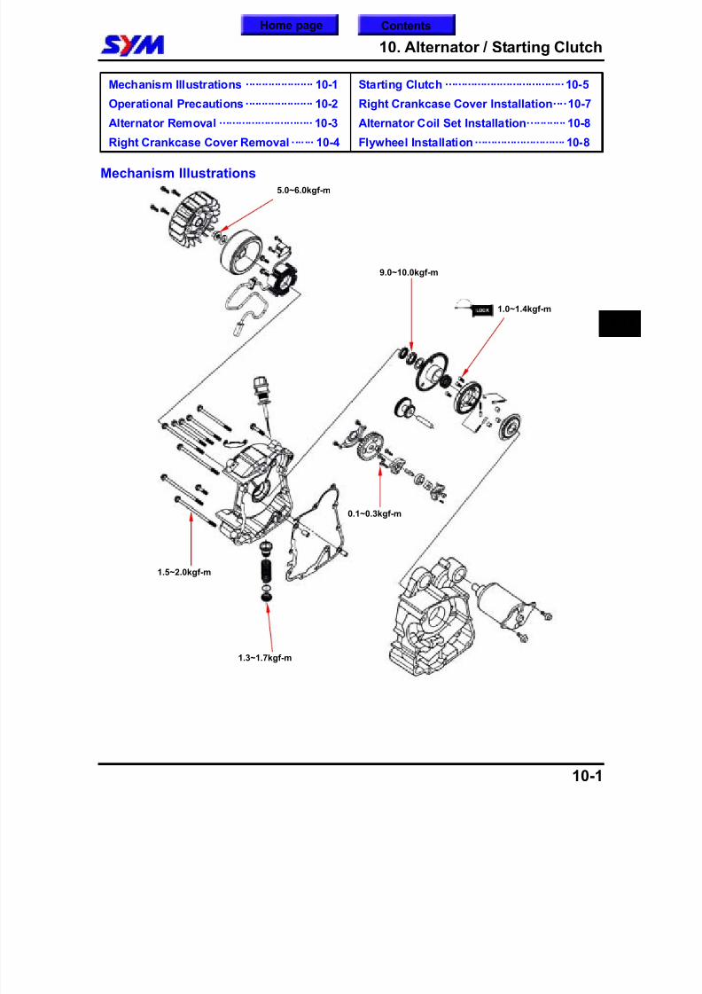
8/12/2019 SYM Mio50 Service Manual 000
http://slidepdf.com/reader/full/sym-mio50-service-manual-000 118/215
10. Alternator / Starting Clutch
10-1
Mechanism Illustrations ····················· 10-1
Operational Precautions····················· 10-2
Alternator Removal ····························· 10-3
Right Crankcase Cover Removal ······· 10-4
Starting Clutch ·····································10-5
Right Crankcase Cover Installation····10-7
Alternator Coil Set Installation············ 10-8
Flywheel Installation···························· 10-8
Mechanism Illustrations
10
9.0~10.0kgf-m
1.0~1.4kgf-m
1.5~2.0kgf-m
1.3~1.7kgf-m
5.0~6.0kgf-m
0.1~0.3kgf-m
ContentsHome page
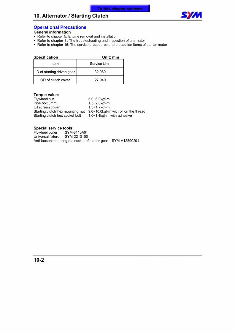
8/12/2019 SYM Mio50 Service Manual 000
http://slidepdf.com/reader/full/sym-mio50-service-manual-000 119/215
10. Alternator / Starting Clutch
10-2
Operational PrecautionsGeneral information Refer to chapter 5: Engine removal and installation Refer to chapter 1 : The troubleshooting and inspection of alternator Refer to chapter 16: The service procedures and precaution items of starter motor
Specification Unit: mm
Item Service Limit
ID of starting driven gear 32.060
OD of clutch cover 27.940
Torque value:Flywheel nut 5.0~6.0kgf-m Pipe bolt 8mm 1.5~2.0kgf-m Oil screen cover 1.3~1.7kgf-m Starting clutch hex mounting nut 9.0~10.0kgf-m with oil on the thread Starting clutch hex socket bolt 1.0~1.4kgf-m with adhesive
Special service toolsFlywheel puller SYM-3110A01Universal fixture SYM-2210100 Anti-loosen mounting nut socket of starter gear SYM-A12590201
To this chapter contents
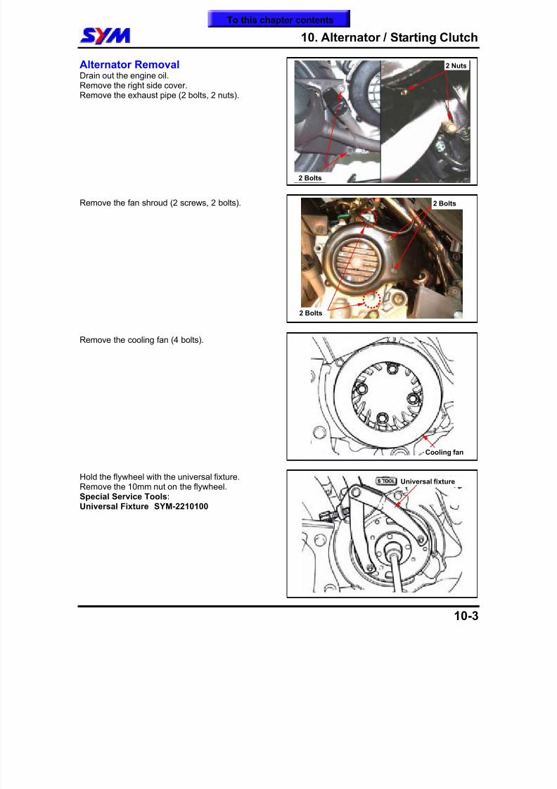
8/12/2019 SYM Mio50 Service Manual 000
http://slidepdf.com/reader/full/sym-mio50-service-manual-000 120/215
10. Alternator / Starting Clutch
10-3
Alternator RemovalDrain out the engine oil.Remove the right side cover.Remove the exhaust pipe (2 bolts, 2 nuts).
Remove the fan shroud (2 screws, 2 bolts).
Remove the cooling fan (4 bolts).
Hold the flywheel with the universal fixture.Remove the 10mm nut on the flywheel.Special Service Tools:Universal Fixture SYM-2210100
Universal fixture
Cooling fan
2 Nuts
2 Bolts
2 Bolts
2 Bolts
To this chapter contents
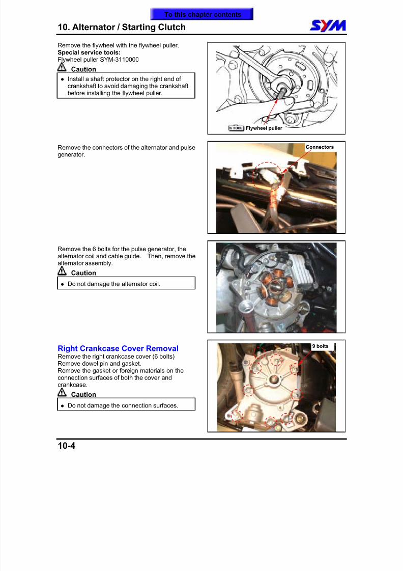
8/12/2019 SYM Mio50 Service Manual 000
http://slidepdf.com/reader/full/sym-mio50-service-manual-000 121/215
10. Alternator / Starting Clutch
10-4
Remove the flywheel with the flywheel puller.Special service tools:Flywheel puller SYM-3110000
Caution Install a shaft protector on the right end of
crankshaft to avoid damaging the crankshaftbefore installing the flywheel puller.
Remove the connectors of the alternator and pulsegenerator.
Remove the 6 bolts for the pulse generator, thealternator coil and cable guide. Then, remove thealternator assembly.
Caution
Do not damage the alternator coil.
Right Crankcase Cover RemovalRemove the right crankcase cover (6 bolts)Remove dowel pin and gasket.Remove the gasket or foreign materials on theconnection surfaces of both the cover andcrankcase.
Caution
Do not damage the connection surfaces.
9 bolts
Flywheel puller
Connectors
To this chapter contents
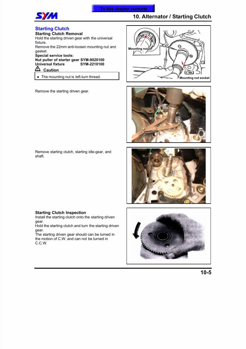
8/12/2019 SYM Mio50 Service Manual 000
http://slidepdf.com/reader/full/sym-mio50-service-manual-000 122/215
10. Alternator / Starting Clutch
10-5
Starting ClutchStarting Clutch RemovalHold the starting driven gear with the universalfixture.Remove the 22mm anti-loosen mounting nut and
gasket.Special service tools:Nut puller of starter gear SYM-9020100Universal fixture SYM-2210100
Caution
The mounting nut is left-turn thread.
Remove the starting driven gear.
Remove starting clutch, starting idle-gear, andshaft.
Starting Clutch InspectionInstall the starting clutch onto the starting drivengear.Hold the starting clutch and turn the starting drivengear.The starting driven gear should can be turned inthe motion of C.W. and can not be turned inC.C.W.
Mounting nut
Mounting nut socket
To this chapter contents
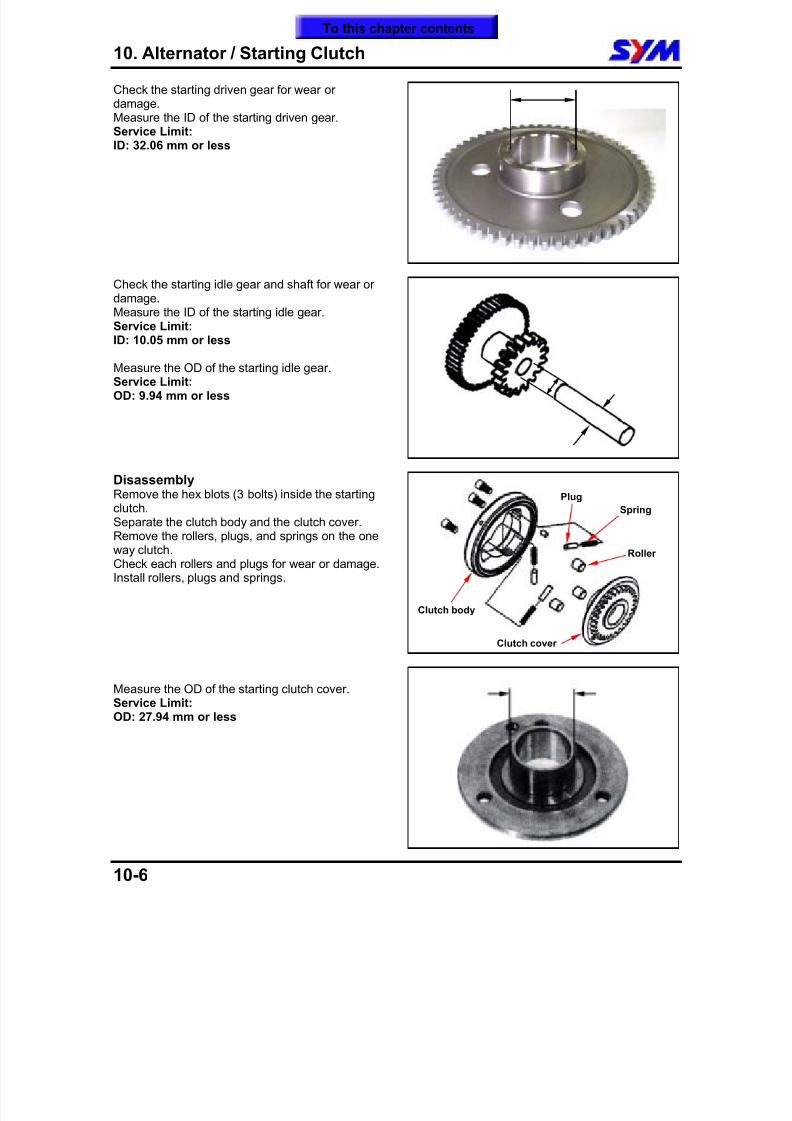
8/12/2019 SYM Mio50 Service Manual 000
http://slidepdf.com/reader/full/sym-mio50-service-manual-000 123/215
10. Alternator / Starting Clutch
10-6
Check the starting driven gear for wear ordamage.Measure the ID of the starting driven gear.Service Limit:ID: 32.06 mm or less
Check the starting idle gear and shaft for wear ordamage.Measure the ID of the starting idle gear.
Service Limit:ID: 10.05 mm or less
Measure the OD of the starting idle gear.Service Limit:OD: 9.94 mm or less
DisassemblyRemove the hex blots (3 bolts) inside the startingclutch.Separate the clutch body and the clutch cover.Remove the rollers, plugs, and springs on the oneway clutch.Check each rollers and plugs for wear or damage.Install rollers, plugs and springs.
Measure the OD of the starting clutch cover.Service Limit:OD: 27.94 mm or less
Spring
Roller
Plug
Clutch body
Clutch cover
To this chapter contents
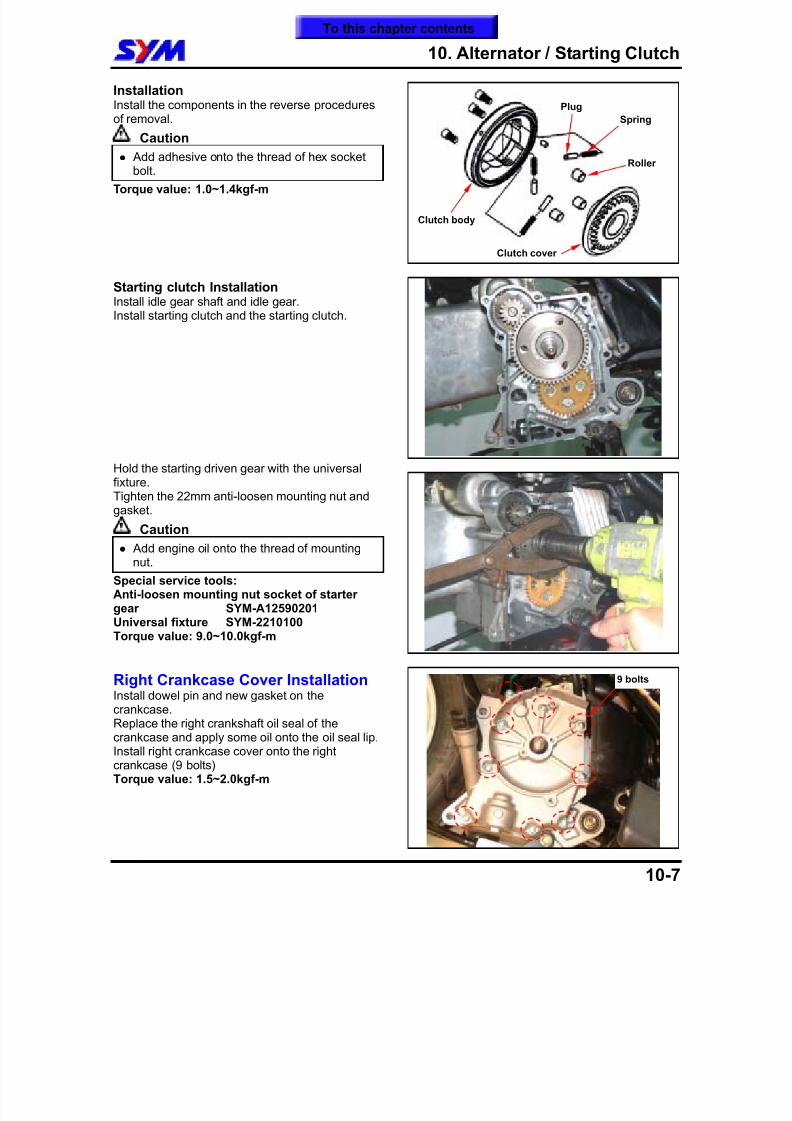
8/12/2019 SYM Mio50 Service Manual 000
http://slidepdf.com/reader/full/sym-mio50-service-manual-000 124/215
10. Alternator / Starting Clutch
10-7
InstallationInstall the components in the reverse proceduresof removal.
Caution
Add adhesive onto the thread of hex socketbolt. Torque value: 1.0~1.4kgf-m
Starting clutch InstallationInstall idle gear shaft and idle gear.Install starting clutch and the starting clutch.
Hold the starting driven gear with the universalfixture.Tighten the 22mm anti-loosen mounting nut andgasket.
Caution Add engine oil onto the thread of mounting
nut. Special service tools:Anti-loosen mounting nut socket of startergear SYM-A12590201Universal fixture SYM-2210100Torque value: 9.0~10.0kgf-m
Right Crankcase Cover InstallationInstall dowel pin and new gasket on thecrankcase.Replace the right crankshaft oil seal of thecrankcase and apply some oil onto the oil seal lip.Install right crankcase cover onto the rightcrankcase (9 bolts)Torque value: 1.5~2.0kgf-m
Spring
Roller
Plug
Clutch body
Clutch cover
9 bolts
To this chapter contents
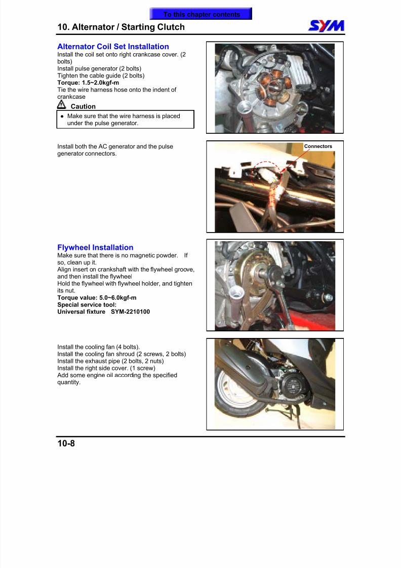
8/12/2019 SYM Mio50 Service Manual 000
http://slidepdf.com/reader/full/sym-mio50-service-manual-000 125/215
10. Alternator / Starting Clutch
10-8
Alternator Coil Set InstallationInstall the coil set onto right crankcase cover. (2bolts)Install pulse generator (2 bolts)Tighten the cable guide (2 bolts)
Torque: 1.5~2.0kgf-mTie the wire harness hose onto the indent ofcrankcase
Caution Make sure that the wire harness is placed
under the pulse generator.
Install both the AC generator and the pulsegenerator connectors.
Flywheel InstallationMake sure that there is no magnetic powder. Ifso, clean up it. Align insert on crankshaft with the flywheel groove,and then install the flywheelHold the flywheel with flywheel holder, and tightenits nut.Torque value: 5.0~6.0kgf-mSpecial service tool:Universal fixture SYM-2210100
Install the cooling fan (4 bolts).Install the cooling fan shroud (2 screws, 2 bolts)Install the exhaust pipe (2 bolts, 2 nuts)Install the right side cover. (1 screw) Add some engine oil according the specifiedquantity.
Connectors
To this chapter contents
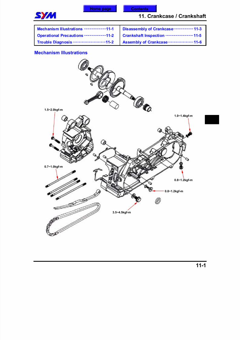
8/12/2019 SYM Mio50 Service Manual 000
http://slidepdf.com/reader/full/sym-mio50-service-manual-000 126/215
11. Crankcase / Crankshaft
11-1
Mechanism Illustrations ····················11-1
Operational Precautions····················11-2
Trouble Diagnosis ······························11-2
Disassembly of Crankcase·················· 11-3
Crankshaft Inspection ························· 11-5
Assembly of Crankcase·······················11-6
Mechanism Illustrations
11
0.8~1.2kgf-m
0.8~1.2kgf-m
3.5~4.5kgf-m
1.5~2.0kgf-m
1.0~1.4kgf-m
0.7~1.0kgf-m
ContentsHome page
8/12/2019 SYM Mio50 Service Manual 000
http://slidepdf.com/reader/full/sym-mio50-service-manual-000 127/215
11. Crankcase / Crankshaft
11-2
Operational PrecautionsGeneral information This Section contains descriptions concerning disassembly of the crankcase so that the crankshaft can
be serviced.
Complete following operations before disassembling crankcase.Engine Chapter 5Cylinder head Chapter 6Cylinder and piston Chapter 7V-belt Drive pulley Chapter 8 Alternator/Foot Starting Clutch Chapter 10Start motor Chapter 16
If the crankshaft bearing or timing sprocket need be replaced, then the crankshaft set have to replaced.
Specification Unit: mm
Item Standard Limit
Left, right clearance of the big end of the connecting rod 0.100~0.300 0.550
Right angle clearance of the big end of the connecting rod 0.000~0.008 0.050
Run-out ¢w 0.100
Torque valueBolts for crankcase 1.5 ~ 2.0kgf-mBolts for cylinder/cylinder head 0.7 ~ 1.0kgf-m
Engine oil draining plug 3.5 ~ 4.5kgf-mBolts for cam chain tensioner 0.8 ~ 1.2kgf-m
Special Service ToolsOil seal (25X37X6) pressing tools SYM-9121600
Trouble DiagnosisEngine noise Loose crankshaft bearing Loose crankshaft pin bearing Wear piston pin or piston pin hole
To this chapter contents
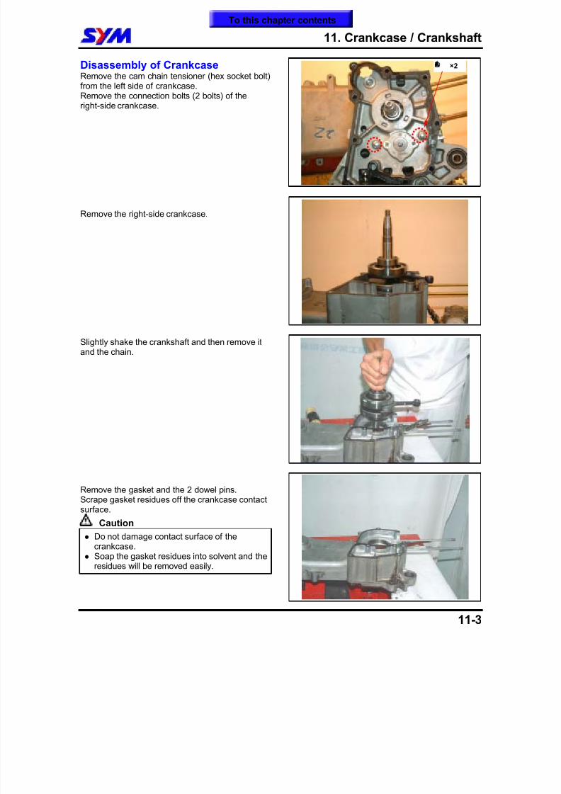
8/12/2019 SYM Mio50 Service Manual 000
http://slidepdf.com/reader/full/sym-mio50-service-manual-000 128/215
11. Crankcase / Crankshaft
11-3
Disassembly of CrankcaseRemove the cam chain tensioner (hex socket bolt)from the left side of crankcase.Remove the connection bolts (2 bolts) of theright-side crankcase.
Remove the right-side crankcase.
Slightly shake the crankshaft and then remove itand the chain.
Remove the gasket and the 2 dowel pins.Scrape gasket residues off the crankcase contactsurface.
Caution Do not damage contact surface of the
crankcase. Soap the gasket residues into solvent and the
residues will be removed easily.
Á® ×2
To this chapter contents
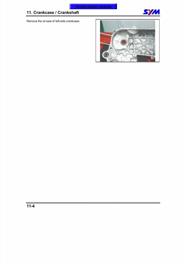
8/12/2019 SYM Mio50 Service Manual 000
http://slidepdf.com/reader/full/sym-mio50-service-manual-000 129/215
11. Crankcase / Crankshaft
11-4
Remove the oil seal of left-side crankcase.
To this chapter contents
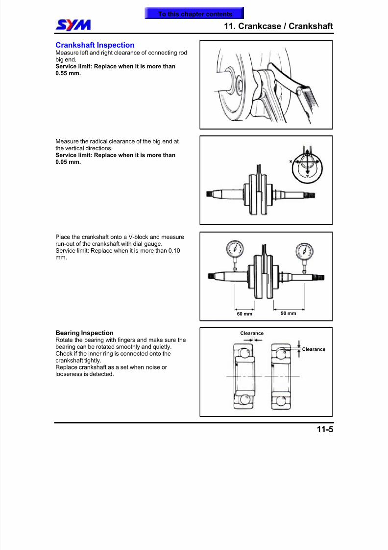
8/12/2019 SYM Mio50 Service Manual 000
http://slidepdf.com/reader/full/sym-mio50-service-manual-000 130/215
11. Crankcase / Crankshaft
11-5
Crankshaft InspectionMeasure left and right clearance of connecting rodbig end.Service limit: Replace when it is more than0.55 mm.
Measure the radical clearance of the big end atthe vertical directions.Service limit: Replace when it is more than
0.05 mm.
Place the crankshaft onto a V-block and measurerun-out of the crankshaft with dial gauge.Service limit: Replace when it is more than 0.10mm.
Bearing InspectionRotate the bearing with fingers and make sure thebearing can be rotated smoothly and quietly.Check if the inner ring is connected onto thecrankshaft tightly.Replace crankshaft as a set when noise orlooseness is detected.
60 mm 90 mm
Clearance
Clearance
To this chapter contents
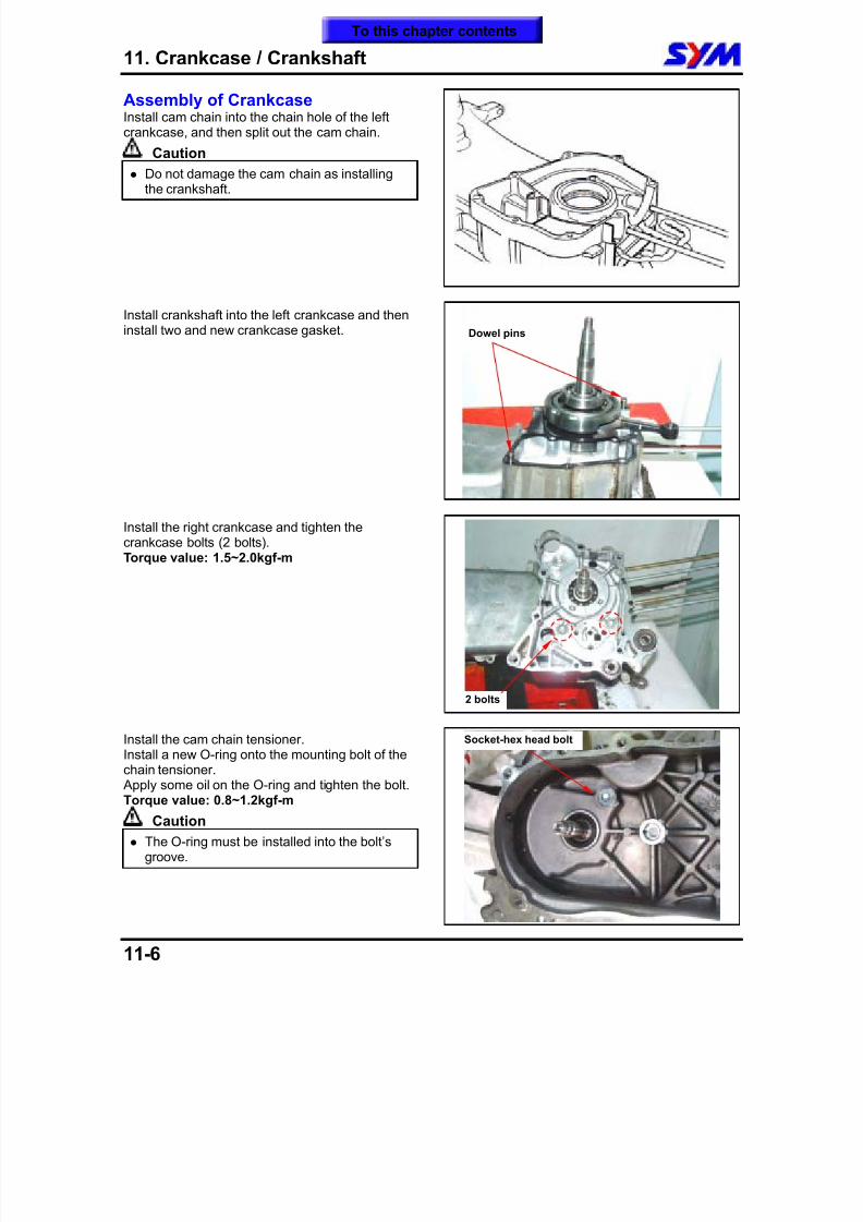
8/12/2019 SYM Mio50 Service Manual 000
http://slidepdf.com/reader/full/sym-mio50-service-manual-000 131/215
11. Crankcase / Crankshaft
11-6
Assembly of CrankcaseInstall cam chain into the chain hole of the leftcrankcase, and then split out the cam chain.
Caution
Do not damage the cam chain as installingthe crankshaft.
Install crankshaft into the left crankcase and theninstall two and new crankcase gasket.
Install the right crankcase and tighten thecrankcase bolts (2 bolts).Torque value: 1.5~2.0kgf-m
Install the cam chain tensioner.Install a new O-ring onto the mounting bolt of thechain tensioner. Apply some oil on the O-ring and tighten the bolt.Torque value: 0.8~1.2kgf-m
Caution The O-ring must be installed into the bolt’s
groove.
Socket-hex head bolt
Dowel pins
2 bolts
To this chapter contents
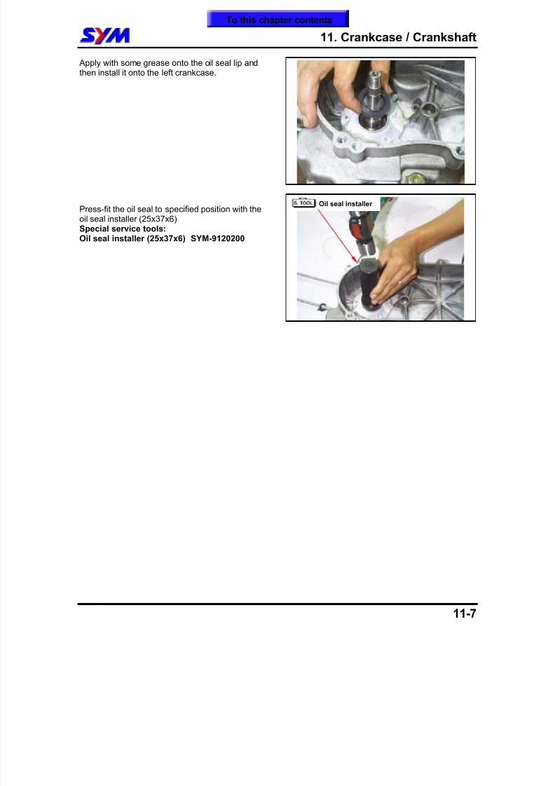
8/12/2019 SYM Mio50 Service Manual 000
http://slidepdf.com/reader/full/sym-mio50-service-manual-000 132/215
11. Crankcase / Crankshaft
11-7
Apply with some grease onto the oil seal lip andthen install it onto the left crankcase.
Press-fit the oil seal to specified position with theoil seal installer (25x37x6)
Special service tools:Oil seal installer (25x37x6) SYM-9120200
Oil seal installer
To this chapter contents

8/12/2019 SYM Mio50 Service Manual 000
http://slidepdf.com/reader/full/sym-mio50-service-manual-000 133/215
11. Crankcase / Crankshaft
11-8
Notes:
To this chapter contents
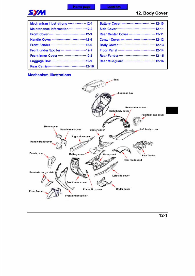
8/12/2019 SYM Mio50 Service Manual 000
http://slidepdf.com/reader/full/sym-mio50-service-manual-000 134/215
12. Body Cover
12-1
Mechanism Illustrations ····················12-1
Maintenance Information ···················12-2
Front Cover·········································12-3
Handle Cover ······································12-4
Front Fender ·······································12-6
Front under Spoiler ····························12-7
Front Inner Cover ·······························12-8
Luggage Box·······································12-9
Rear Carrier·········································12-10
Battery Cover ····································· 12-10
Side Cover ·········································· 12-11
Rear Center Cover ····························· 12-11
Center Cover ······································ 12-12
Body Cover········································· 12-13
Floor Panel ········································· 12-14
Rear Fender ········································ 12-15
Rear Mudguard··································· 12-16
Mechanism Illustrations
12
Luggage box
Rear fender
Seat
Handle rear cover
Handle front cover
Front inner cover
Front cover
Front fender
Floor panel
Center cover Left body cover
Right body cover
Right side cover
Left side cover
Rear center cover
Under cover
Front under spoiler
Battery cover
Rear mudguard
Front winker garnish
Frame No. cover
Fuel tank cap cover
Meter cover
Home page Contents
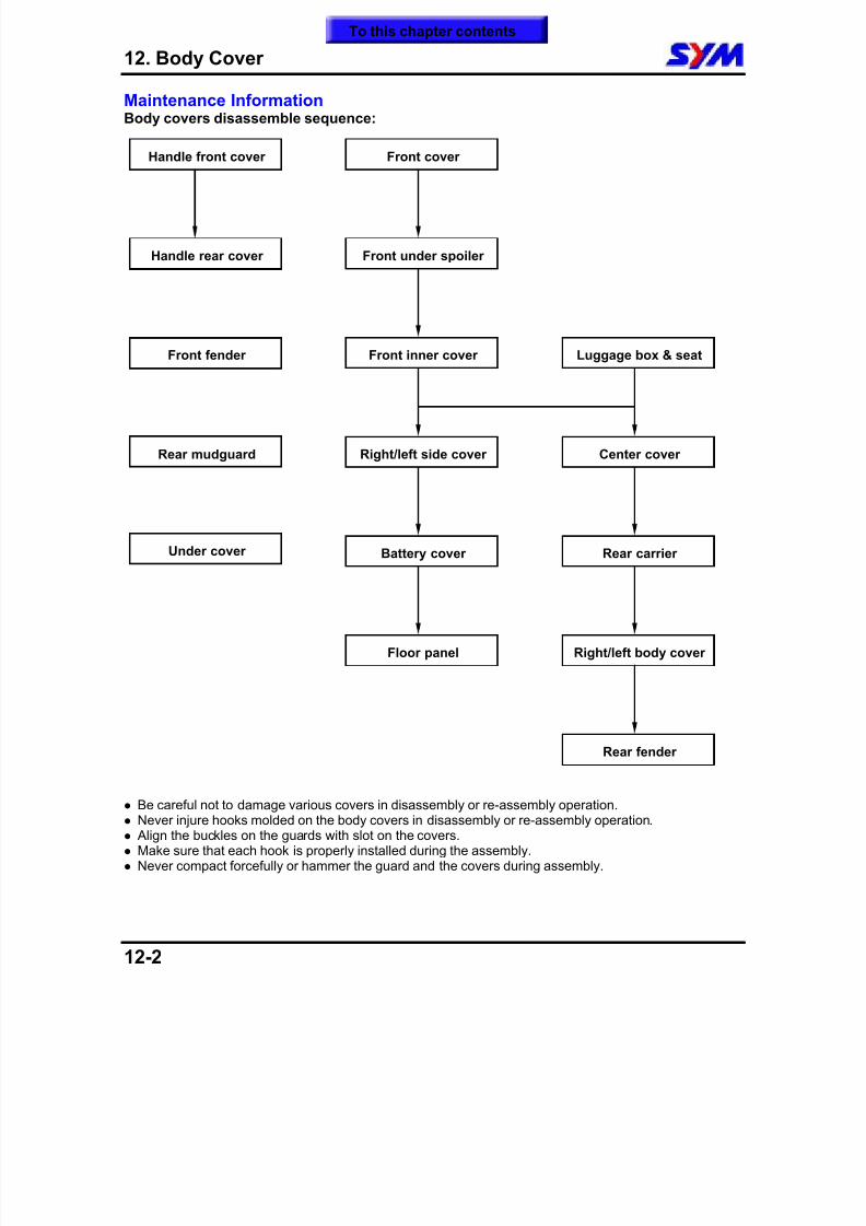
8/12/2019 SYM Mio50 Service Manual 000
http://slidepdf.com/reader/full/sym-mio50-service-manual-000 135/215
12. Body Cover
12-2
Maintenance InformationBody covers disassemble sequence:
Be careful not to damage various covers in disassembly or re-assembly operation. Never injure hooks molded on the body covers in disassembly or re-assembly operation. Align the buckles on the guards with slot on the covers. Make sure that each hook is properly installed during the assembly. Never compact forcefully or hammer the guard and the covers during assembly.
Right/left side cover
Front cover
Front under spoiler
Luggage box & seat
Rear carrierUnder cover
Front inner cover
Handle front cover
Right/left body cover
Handle rear cover
Floor panel
Rear fender
Center cover
Front fender
Battery cover
Rear mudguard
To this chapter contents
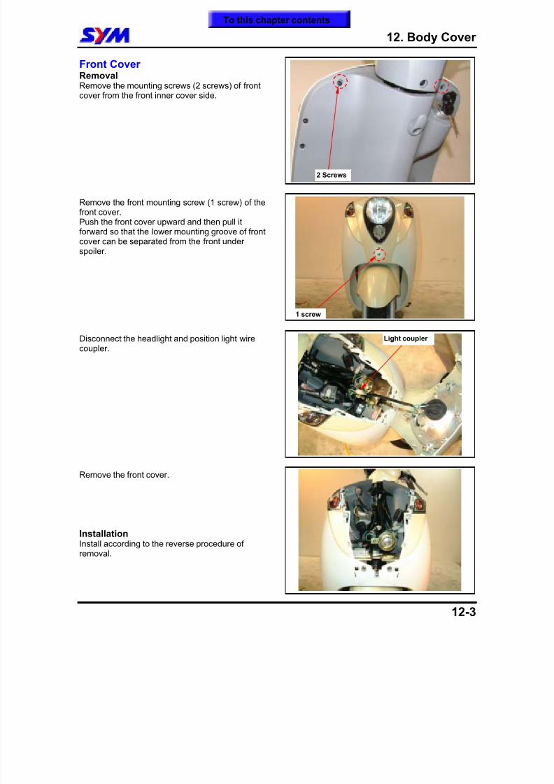
8/12/2019 SYM Mio50 Service Manual 000
http://slidepdf.com/reader/full/sym-mio50-service-manual-000 136/215
12. Body Cover
12-3
Front CoverRemovalRemove the mounting screws (2 screws) of frontcover from the front inner cover side.
Remove the front mounting screw (1 screw) of thefront cover.Push the front cover upward and then pull itforward so that the lower mounting groove of frontcover can be separated from the front underspoiler.
Disconnect the headlight and position light wirecoupler.
Remove the front cover.
InstallationInstall according to the reverse procedure ofremoval.
1 screw
Light coupler
2 Screws
To this chapter contents
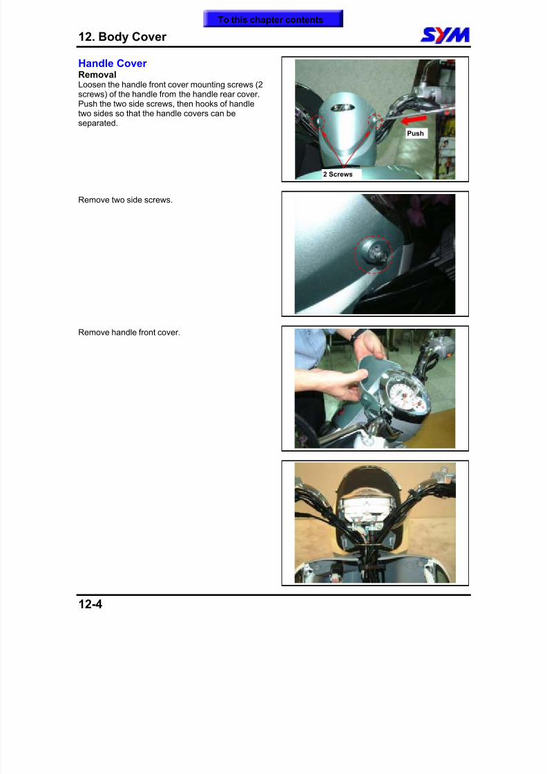
8/12/2019 SYM Mio50 Service Manual 000
http://slidepdf.com/reader/full/sym-mio50-service-manual-000 137/215
12. Body Cover
12-4
Handle CoverRemovalLoosen the handle front cover mounting screws (2screws) of the handle from the handle rear cover.Push the two side screws, then hooks of handle
two sides so that the handle covers can beseparated.
Remove two side screws.
Remove handle front cover.
Push
2 Screws
To this chapter contents
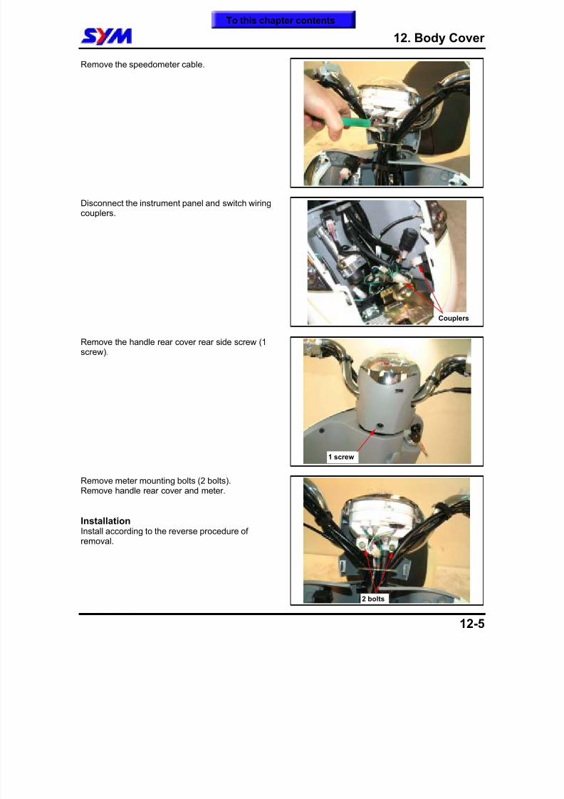
8/12/2019 SYM Mio50 Service Manual 000
http://slidepdf.com/reader/full/sym-mio50-service-manual-000 138/215
12. Body Cover
12-5
Remove the speedometer cable.
Disconnect the instrument panel and switch wiringcouplers.
Remove the handle rear cover rear side screw (1
screw).
Remove meter mounting bolts (2 bolts).Remove handle rear cover and meter.
InstallationInstall according to the reverse procedure ofremoval.
Couplers
2 bolts
1 screw
To this chapter contents
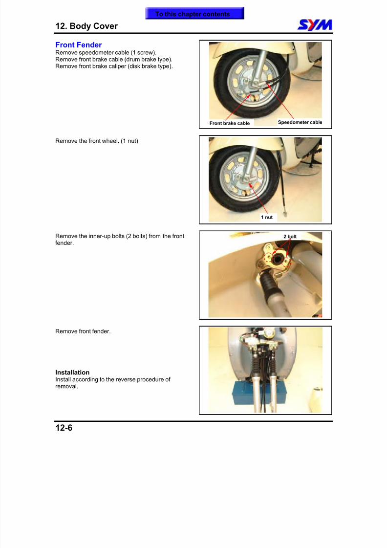
8/12/2019 SYM Mio50 Service Manual 000
http://slidepdf.com/reader/full/sym-mio50-service-manual-000 139/215
12. Body Cover
12-6
Front FenderRemove speedometer cable (1 screw).Remove front brake cable (drum brake type).Remove front brake caliper (disk brake type).
Remove the front wheel. (1 nut)
Remove the inner-up bolts (2 bolts) from the frontfender.
Remove front fender.
InstallationInstall according to the reverse procedure ofremoval.
Speedometer cableFront brake cable
1 nut
2 bolt
To this chapter contents
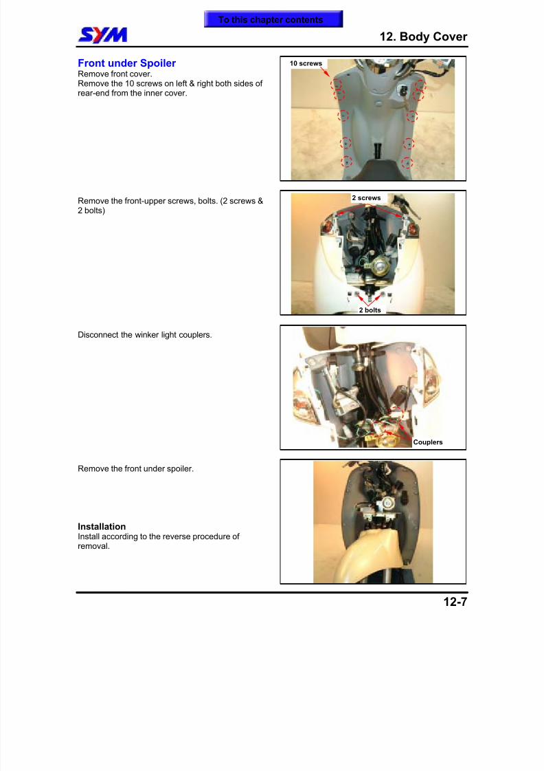
8/12/2019 SYM Mio50 Service Manual 000
http://slidepdf.com/reader/full/sym-mio50-service-manual-000 140/215
12. Body Cover
12-7
Front under SpoilerRemove front cover.Remove the 10 screws on left & right both sides ofrear-end from the inner cover.
Remove the front-upper screws, bolts. (2 screws &2 bolts)
Disconnect the winker light couplers.
Remove the front under spoiler.
InstallationInstall according to the reverse procedure ofremoval.
2 screws
10 screws
2 bolts
Couplers
To this chapter contents
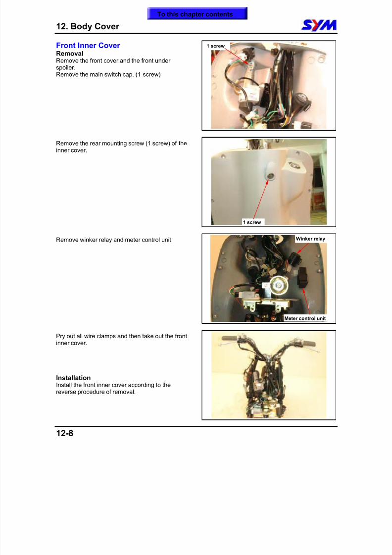
8/12/2019 SYM Mio50 Service Manual 000
http://slidepdf.com/reader/full/sym-mio50-service-manual-000 141/215
12. Body Cover
12-8
Front Inner CoverRemovalRemove the front cover and the front underspoiler.Remove the main switch cap. (1 screw)
Remove the rear mounting screw (1 screw) of theinner cover.
Remove winker relay and meter control unit.
Pry out all wire clamps and then take out the frontinner cover.
InstallationInstall the front inner cover according to thereverse procedure of removal.
1 screw
1 screw
Meter control unit
Winker relay
To this chapter contents
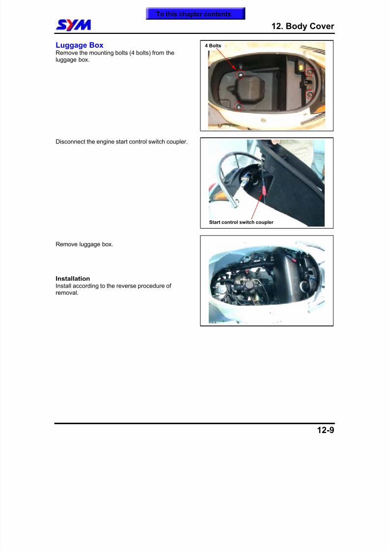
8/12/2019 SYM Mio50 Service Manual 000
http://slidepdf.com/reader/full/sym-mio50-service-manual-000 142/215
12. Body Cover
12-9
Luggage BoxRemove the mounting bolts (4 bolts) from theluggage box.
Disconnect the engine start control switch coupler.
Remove luggage box.
InstallationInstall according to the reverse procedure ofremoval.
4 Bolts
Start control switch coupler
To this chapter contents
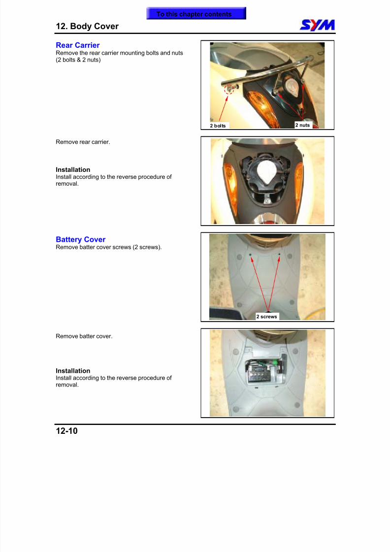
8/12/2019 SYM Mio50 Service Manual 000
http://slidepdf.com/reader/full/sym-mio50-service-manual-000 143/215
12. Body Cover
12-10
Rear CarrierRemove the rear carrier mounting bolts and nuts(2 bolts & 2 nuts)
Remove rear carrier.
InstallationInstall according to the reverse procedure ofremoval.
Battery CoverRemove batter cover screws (2 screws).
Remove batter cover.
InstallationInstall according to the reverse procedure ofremoval.
2 bolts
2 screws
2 nuts
To this chapter contents
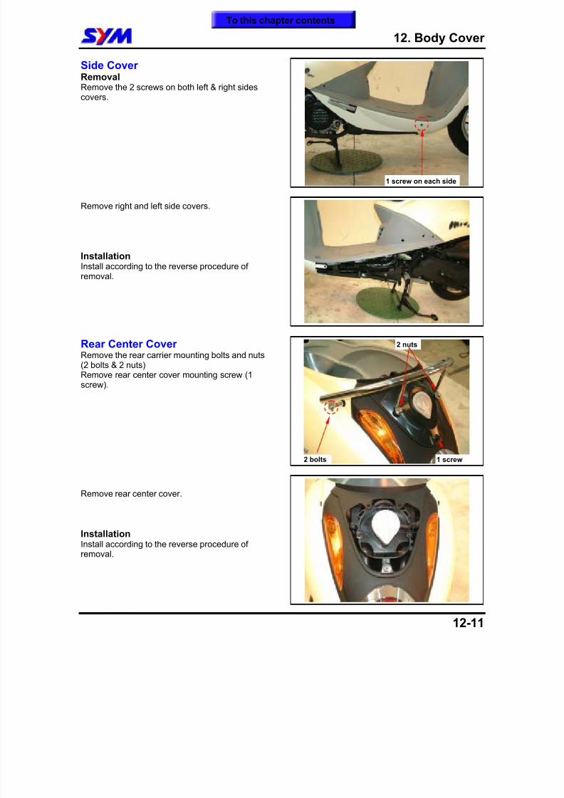
8/12/2019 SYM Mio50 Service Manual 000
http://slidepdf.com/reader/full/sym-mio50-service-manual-000 144/215
12. Body Cover
12-11
Side CoverRemovalRemove the 2 screws on both left & right sidescovers.
Remove right and left side covers.
InstallationInstall according to the reverse procedure ofremoval.
Rear Center CoverRemove the rear carrier mounting bolts and nuts(2 bolts & 2 nuts)Remove rear center cover mounting screw (1screw).
Remove rear center cover.
InstallationInstall according to the reverse procedure ofremoval.
1 screw on each side
2 bolts
2 nuts
1 screw
To this chapter contents
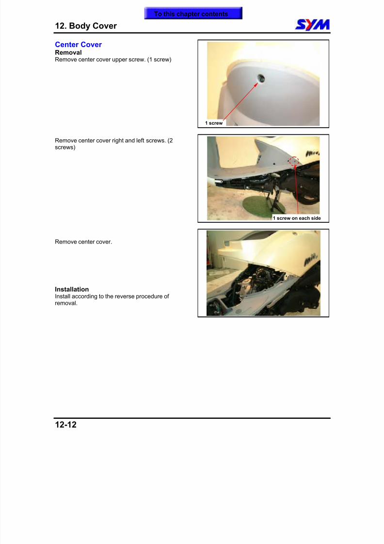
8/12/2019 SYM Mio50 Service Manual 000
http://slidepdf.com/reader/full/sym-mio50-service-manual-000 145/215
12. Body Cover
12-12
Center CoverRemovalRemove center cover upper screw. (1 screw)
Remove center cover right and left screws. (2screws)
Remove center cover.
InstallationInstall according to the reverse procedure ofremoval.
1 screw
1 screw on each side
To this chapter contents
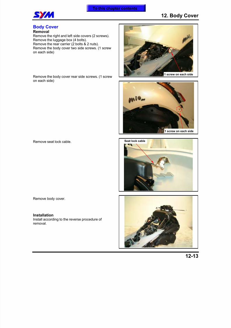
8/12/2019 SYM Mio50 Service Manual 000
http://slidepdf.com/reader/full/sym-mio50-service-manual-000 146/215
12. Body Cover
12-13
Body CoverRemovalRemove the right and left side covers (2 screws).Remove the luggage box (4 bolts).Remove the rear carrier (2 bolts & 2 nuts).
Remove the body cover two side screws. (1 screwon each side)
Remove the body cover rear side screws. (1 screwon each side)
Remove seat lock cable.
Remove body cover.
InstallationInstall according to the reverse procedure ofremoval.
1 screw on each side
Seat lock cable
1 screw on each side
To this chapter contents
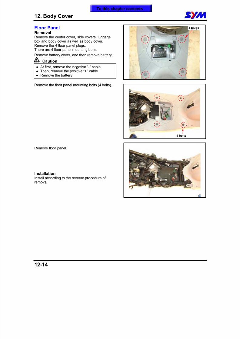
8/12/2019 SYM Mio50 Service Manual 000
http://slidepdf.com/reader/full/sym-mio50-service-manual-000 147/215
12. Body Cover
12-14
Floor PanelRemovalRemove the center cover, side covers, luggagebox and body cover as well as body cover.Remove the 4 floor panel plugs.
There are 4 floor panel mounting bolts.Remove battery cover, and then remove battery.
Caution At first, remove the negative “-“ cable Then, remove the positive “+” cable Remove the battery
Remove the floor panel mounting bolts (4 bolts).
Remove floor panel.
InstallationInstall according to the reverse procedure ofremoval.
4 plugs
4 bolts
To this chapter contents
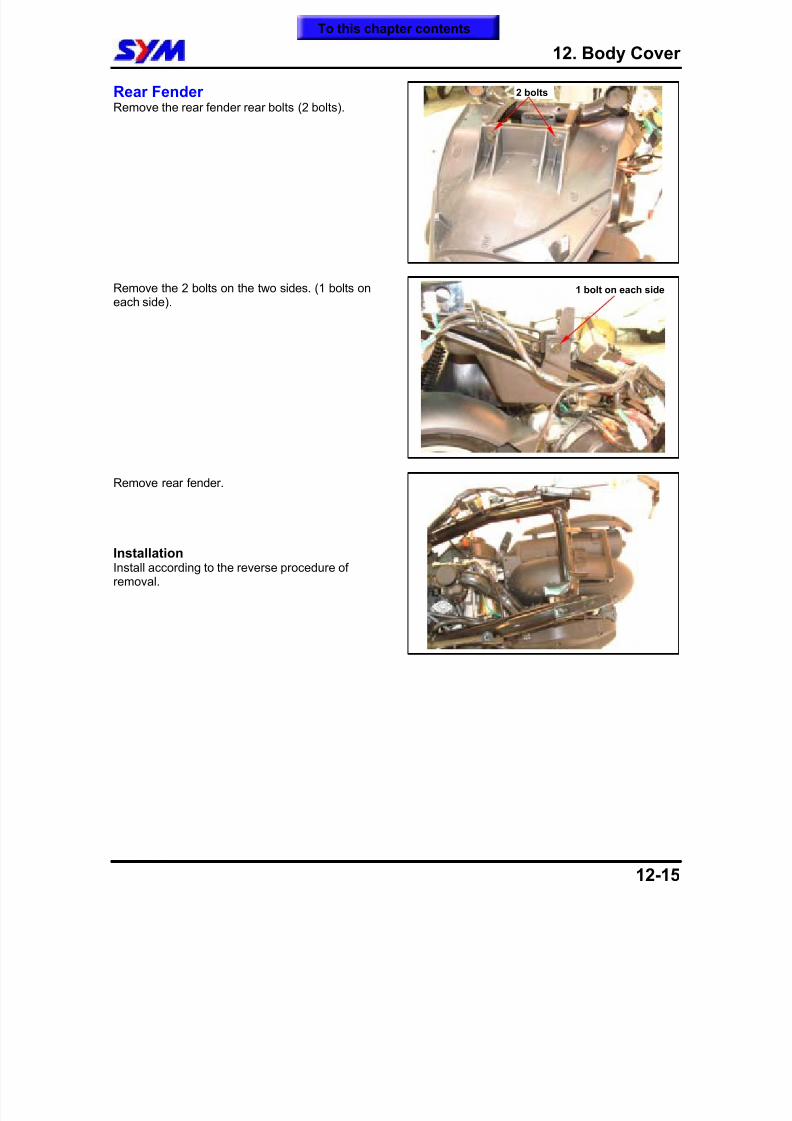
8/12/2019 SYM Mio50 Service Manual 000
http://slidepdf.com/reader/full/sym-mio50-service-manual-000 148/215
12. Body Cover
12-15
Rear FenderRemove the rear fender rear bolts (2 bolts).
Remove the 2 bolts on the two sides. (1 bolts oneach side).
Remove rear fender.
InstallationInstall according to the reverse procedure ofremoval.
2 bolts
1 bolt on each side
To this chapter contents
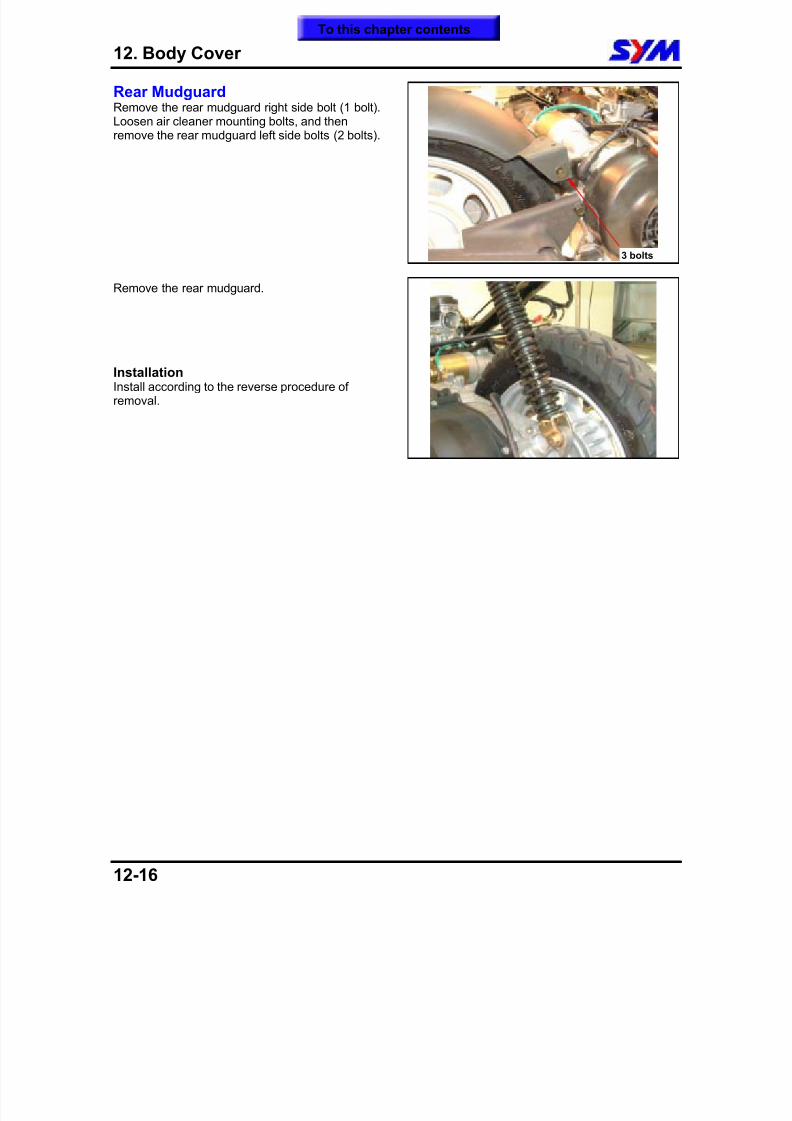
8/12/2019 SYM Mio50 Service Manual 000
http://slidepdf.com/reader/full/sym-mio50-service-manual-000 149/215
12. Body Cover
12-16
Rear MudguardRemove the rear mudguard right side bolt (1 bolt).Loosen air cleaner mounting bolts, and thenremove the rear mudguard left side bolts (2 bolts).
Remove the rear mudguard.
InstallationInstall according to the reverse procedure ofremoval.
3 bolts
To this chapter contents
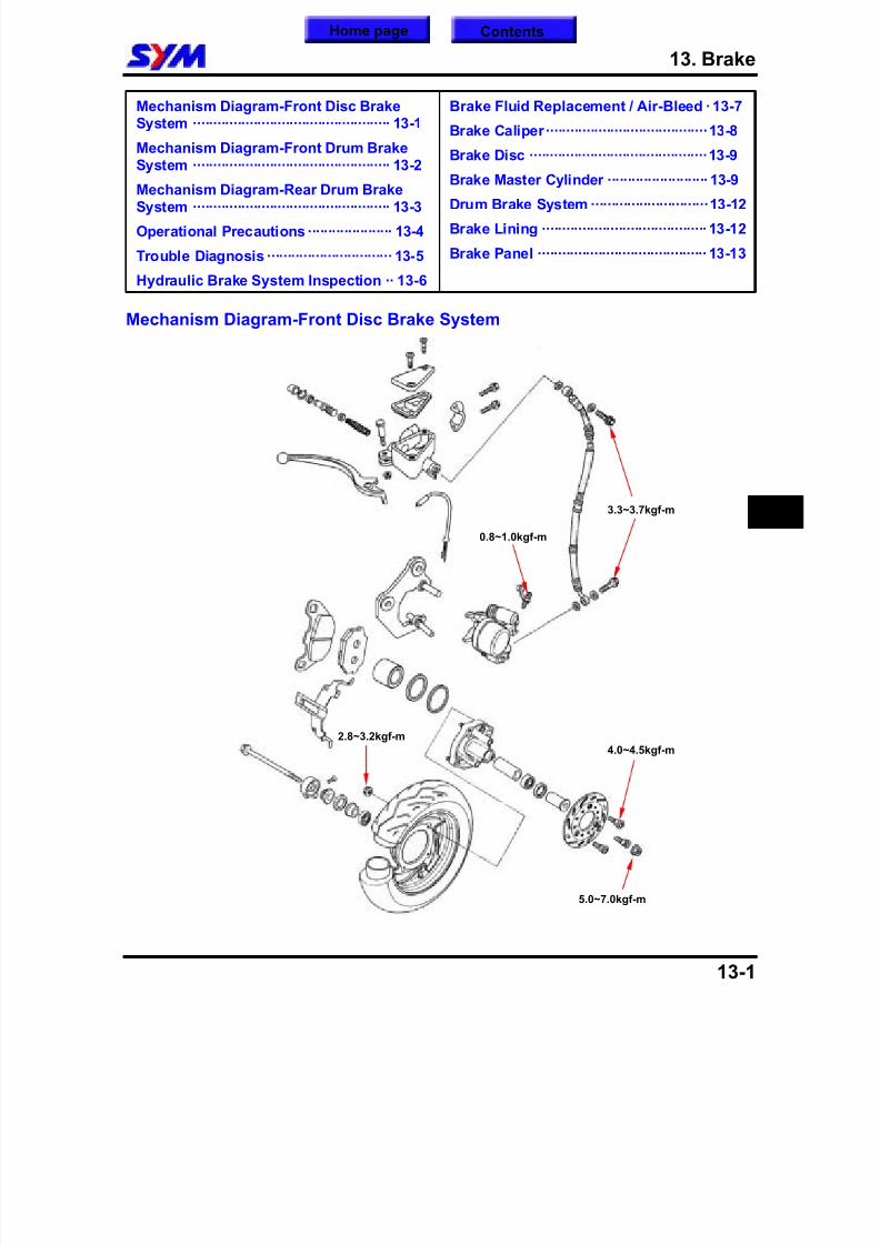
8/12/2019 SYM Mio50 Service Manual 000
http://slidepdf.com/reader/full/sym-mio50-service-manual-000 150/215
13. Brake
13-1
Mechanism Diagram-Front Disc BrakeSystem ················································· 13-1
Mechanism Diagram-Front Drum BrakeSystem ················································· 13-2
Mechanism Diagram-Rear Drum BrakeSystem ················································· 13-3
Operational Precautions····················· 13-4
Trouble Diagnosis ······························· 13-5
Hydraulic Brake System Inspection ·· 13-6
Brake Fluid Replacement / Air-Bleed ·13-7
Brake Caliper········································13-8
Brake Disc ············································13-9
Brake Master Cylinder ························· 13-9
Drum Brake System ·····························13-12
Brake Lining ·········································13-12
Brake Panel ··········································13-13
Mechanism Diagram-Front Disc Brake System
13
5.0~7.0kgf-m
4.0~4.5kgf-m
0.8~1.0kgf-m
3.3~3.7kgf-m
2.8~3.2kgf-m
Home page Contents
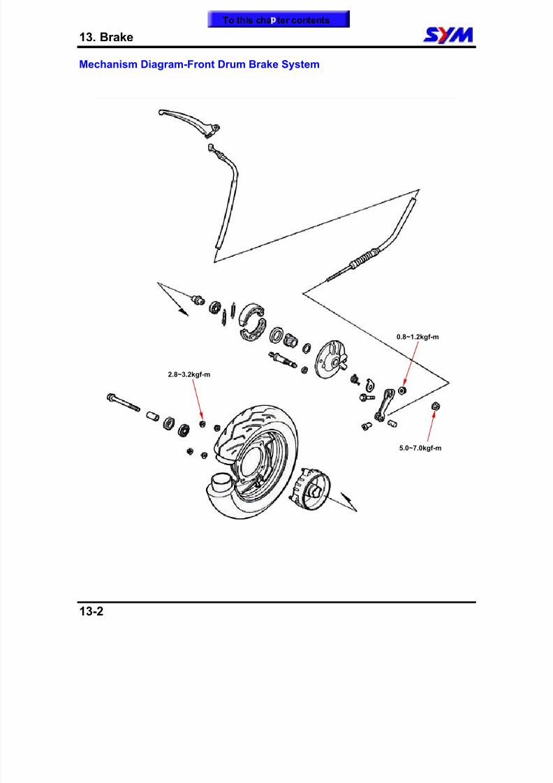
8/12/2019 SYM Mio50 Service Manual 000
http://slidepdf.com/reader/full/sym-mio50-service-manual-000 151/215
13. Brake
13-2
Mechanism Diagram-Front Drum Brake System
0.8~1.2kgf-m
2.8~3.2kgf-m
5.0~7.0kgf-m
To this cha ter contents
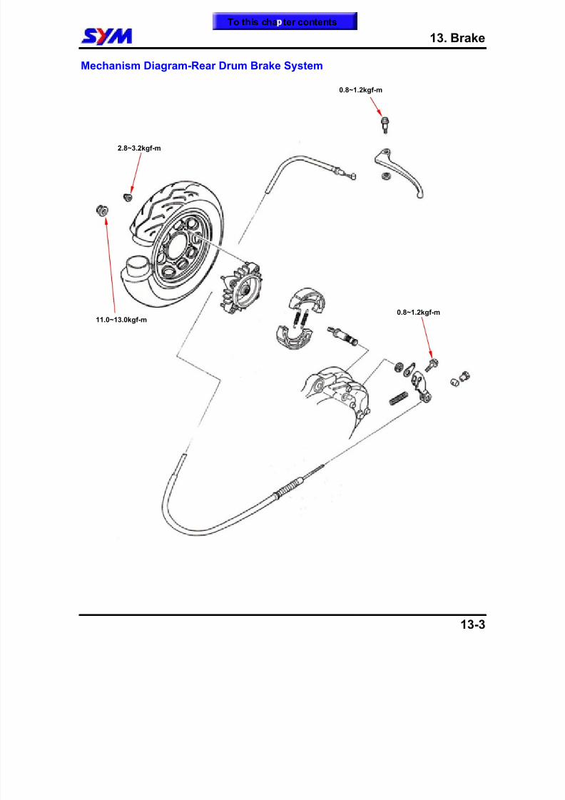
8/12/2019 SYM Mio50 Service Manual 000
http://slidepdf.com/reader/full/sym-mio50-service-manual-000 152/215
13. Brake
13-3
Mechanism Diagram-Rear Drum Brake System
2.8~3.2kgf-m
11.0~13.0kgf-m0.8~1.2kgf-m
0.8~1.2kgf-m
To this cha ter contents
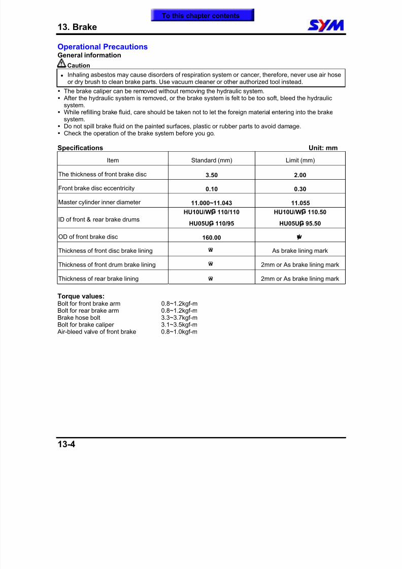
8/12/2019 SYM Mio50 Service Manual 000
http://slidepdf.com/reader/full/sym-mio50-service-manual-000 153/215
13. Brake
13-4
Operational PrecautionsGeneral information
Caution
Inhaling asbestos may cause disorders of respiration system or cancer, therefore, never use air hose
or dry brush to clean brake parts. Use vacuum cleaner or other authorized tool instead. The brake caliper can be removed without removing the hydraulic system. After the hydraulic system is removed, or the brake system is felt to be too soft, bleed the hydraulic
system. While refilling brake fluid, care should be taken not to let the foreign material entering into the brake
system. Do not spill brake fluid on the painted surfaces, plastic or rubber parts to avoid damage. Check the operation of the brake system before you go.
Specifications Unit: mm
Item Standard (mm) Limit (mm)
The thickness of front brake disc 3.50 2.00
Front brake disc eccentricity 0.10 0.30
Master cylinder inner diameter 11.000~11.043 11.055
ID of front & rear brake drums
HU10U/W¡G 110/110
HU05U¡G 110/95
HU10U/W¡G 110.50
HU05U¡G 95.50
OD of front brake disc 160.00 ¢w
Thickness of front disc brake lining As brake lining mark
Thickness of front drum brake lining 2mm or As brake lining mark
Thickness of rear brake lining 2mm or As brake lining mark
Torque values:Bolt for front brake arm 0.8~1.2kgf-mBolt for rear brake arm 0.8~1.2kgf-mBrake hose bolt 3.3~3.7kgf-mBolt for brake caliper 3.1~3.5kgf-m
Air-bleed valve of front brake 0.8~1.0kgf-m
To this chapter contents
8/12/2019 SYM Mio50 Service Manual 000
http://slidepdf.com/reader/full/sym-mio50-service-manual-000 154/215
13. Brake
13-5
Trouble DiagnosisDisc Brake Soft brake lever
1. Air inside the hydraulic system2. Hydraulic system leaking
3. Worn master piston4. Worn brake pad5. Poor brake caliper6. Worn brake lining/disc7. Low brake fluid8. Blocked brake pipe9. Warp/bent brake disc
10. Bent brake lever
Hard operation of brake lever1. Blocked brake system
2. Poor brake caliper3. Blocked brake pipe4. Seized/worn master cylinder piston5. Bent brake lever
Uneven brake1. Dirty brake lining/disc2. Poor wheel alignment
3. Clogged brake hose4. Deformed or warped brake disc5. Restricted brake hose and fittings
Tight brake1. Dirty brake lining/disc2. Poor wheel alignment3. Deformed or warped brake disc
Brake noise1. Dirty lining
2. Deformed brake disc3. Poor brake caliper installation4. Imbalance brake disc or wheel
Drum Brake Poor brake performance
1. improper brake adjustment2. worn brake lining3. worn brake drum4. worn brake cam5. improper brake lining installation6. seized brake cable7. Dirty brake lining8. Dirty brake drum9. brake pad worn in brake cam area.
10. poor contact between brake arm and camshaftindent
Tight operation or low return speed of brakelever
1. worn/broken/crack return spring2. worn drum3. Dirty brake lining4. brake seized caused from dirty brake drum5. seized brake cable6. worn brake cam7. improper brake lining installation
Brake noise1. worn brake lining2. worn drum3. Dirty brake lining4. Dirty brake drum
To this chapter contents
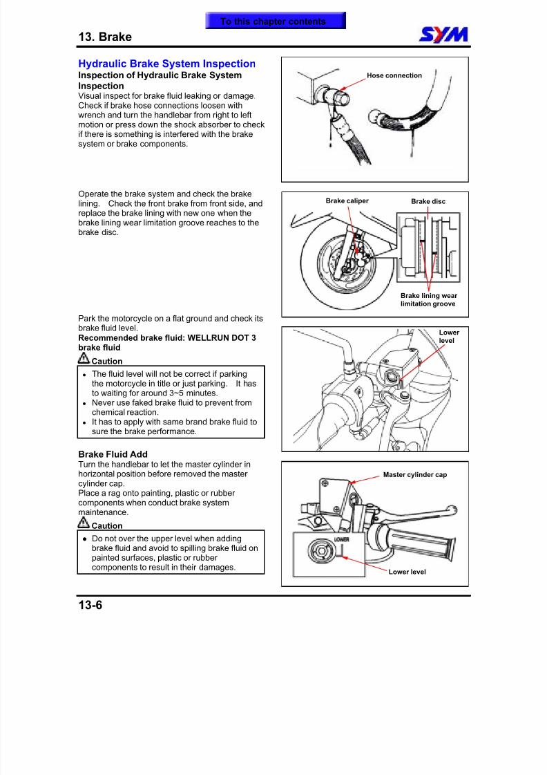
8/12/2019 SYM Mio50 Service Manual 000
http://slidepdf.com/reader/full/sym-mio50-service-manual-000 155/215
13. Brake
13-6
Hydraulic Brake System InspectionInspection of Hydraulic Brake SystemInspectionVisual inspect for brake fluid leaking or damage.Check if brake hose connections loosen with
wrench and turn the handlebar from right to leftmotion or press down the shock absorber to checkif there is something is interfered with the brakesystem or brake components.
Operate the brake system and check the brakelining. Check the front brake from front side, andreplace the brake lining with new one when the
brake lining wear limitation groove reaches to thebrake disc.
Park the motorcycle on a flat ground and check itsbrake fluid level.
Recommended brake fluid: WELLRUN DOT 3brake fluid
Caution
The fluid level will not be correct if parkingthe motorcycle in title or just parking. It hasto waiting for around 3~5 minutes.
Never use faked brake fluid to prevent fromchemical reaction.
It has to apply with same brand brake fluid tosure the brake performance.
Brake Fluid AddTurn the handlebar to let the master cylinder inhorizontal position before removed the mastercylinder cap.Place a rag onto painting, plastic or rubbercomponents when conduct brake systemmaintenance.
Caution
Do not over the upper level when addingbrake fluid and avoid to spilling brake fluid onpainted surfaces, plastic or rubber
components to result in their damages.
Master cylinder cap
Lower level
Brake caliper Brake disc
Brake lining wearlimitation groove
Lower
level
Hose connection
To this chapter contents
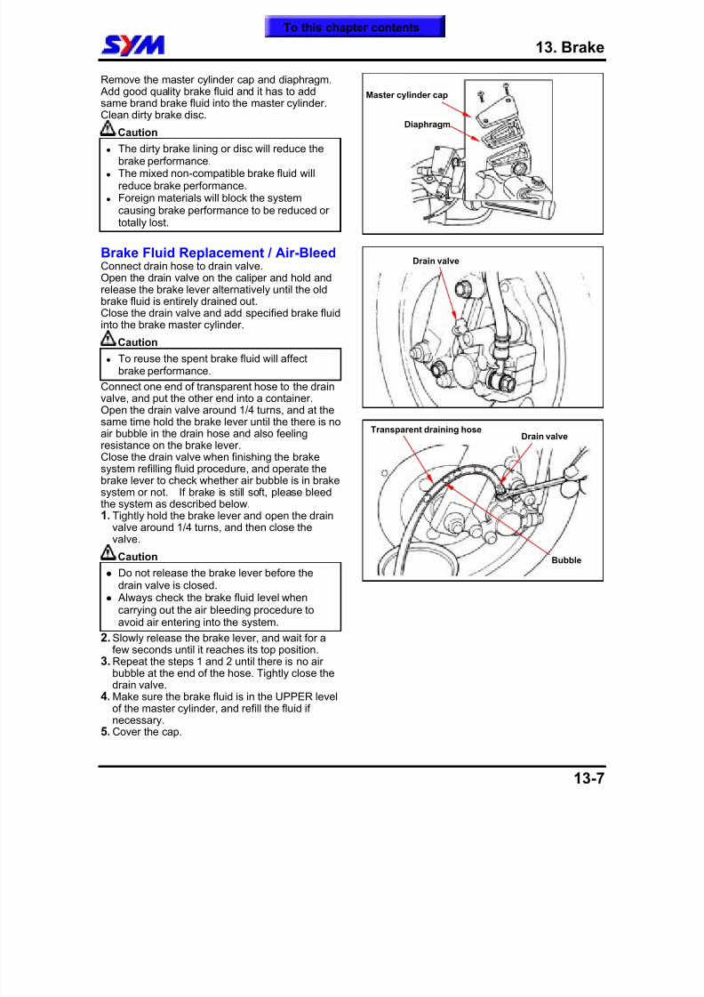
8/12/2019 SYM Mio50 Service Manual 000
http://slidepdf.com/reader/full/sym-mio50-service-manual-000 156/215
13. Brake
13-7
Remove the master cylinder cap and diaphragm. Add good quality brake fluid and it has to addsame brand brake fluid into the master cylinder.Clean dirty brake disc.
Caution
The dirty brake lining or disc will reduce thebrake performance.
The mixed non-compatible brake fluid willreduce brake performance.
Foreign materials will block the systemcausing brake performance to be reduced ortotally lost.
Brake Fluid Replacement / Air-BleedConnect drain hose to drain valve.Open the drain valve on the caliper and hold and
release the brake lever alternatively until the oldbrake fluid is entirely drained out.Close the drain valve and add specified brake fluidinto the brake master cylinder.
Caution
To reuse the spent brake fluid will affectbrake performance.
Connect one end of transparent hose to the drainvalve, and put the other end into a container.Open the drain valve around 1/4 turns, and at thesame time hold the brake lever until the there is no
air bubble in the drain hose and also feelingresistance on the brake lever.Close the drain valve when finishing the brakesystem refilling fluid procedure, and operate thebrake lever to check whether air bubble is in brakesystem or not. If brake is still soft, please bleedthe system as described below.1. Tightly hold the brake lever and open the drain
valve around 1/4 turns, and then close thevalve.
Caution
Do not release the brake lever before thedrain valve is closed.
Always check the brake fluid level whencarrying out the air bleeding procedure toavoid air entering into the system.
2. Slowly release the brake lever, and wait for afew seconds until it reaches its top position.
3. Repeat the steps 1 and 2 until there is no airbubble at the end of the hose. Tightly close thedrain valve.
4. Make sure the brake fluid is in the UPPER levelof the master cylinder, and refill the fluid ifnecessary.
5. Cover the cap.
Transparent draining hose
Bubble
Drain valve
Drain valve
Master cylinder cap
Diaphragm
To this chapter contents
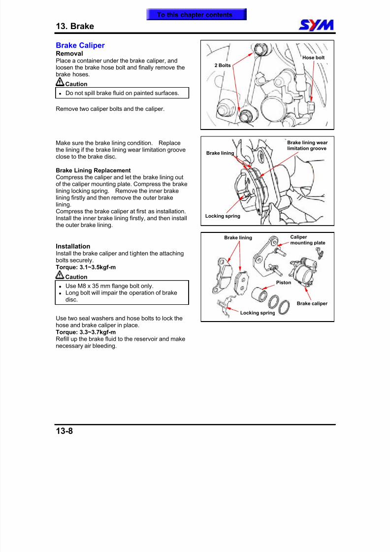
8/12/2019 SYM Mio50 Service Manual 000
http://slidepdf.com/reader/full/sym-mio50-service-manual-000 157/215
13. Brake
13-8
Brake CaliperRemovalPlace a container under the brake caliper, andloosen the brake hose bolt and finally remove thebrake hoses.
Caution
Do not spill brake fluid on painted surfaces.
Remove two caliper bolts and the caliper.
Make sure the brake lining condition. Replacethe lining if the brake lining wear limitation grooveclose to the brake disc.
Brake Lining ReplacementCompress the caliper and let the brake lining outof the caliper mounting plate. Compress the brakelining locking spring. Remove the inner brakelining firstly and then remove the outer brakelining.Compress the brake caliper at first as installation.Install the inner brake lining firstly, and then installthe outer brake lining.
InstallationInstall the brake caliper and tighten the attachingbolts securely.Torque: 3.1~3.5kgf-m
Caution
Use M8 x 35 mm flange bolt only. Long bolt will impair the operation of brake
disc.
Use two seal washers and hose bolts to lock thehose and brake caliper in place.Torque: 3.3~3.7kgf-mRefill up the brake fluid to the reservoir and makenecessary air bleeding.
Brake lining
Locking spring
Brake lining
Brake caliper
Brake lining wearlimitation groove
Caliper
mounting plate
2 Bolts
Hose bolt
Piston
Locking spring
To this chapter contents
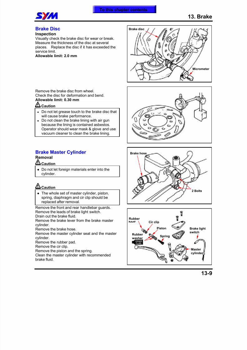
8/12/2019 SYM Mio50 Service Manual 000
http://slidepdf.com/reader/full/sym-mio50-service-manual-000 158/215
13. Brake
13-9
Brake DiscInspection Visually check the brake disc for wear or break.Measure the thickness of the disc at severalplaces. Replace the disc if it has exceeded the
service limit.Allowable limit: 2.0 mm
Remove the brake disc from wheel.Check the disc for deformation and bend.Allowable limit: 0.30 mm
Caution
Do not let grease touch to the brake disc thatwill cause brake performance.
Do not clean the brake lining with air gunbecause the lining is contained asbestos.Operator should wear mask & glove and usevacuum cleaner to clean the brake lining.
Brake Master CylinderRemoval
Caution Do not let foreign materials enter into the
cylinder.
Caution The whole set of master cylinder, piston,
spring, diaphragm and cir clip should be
replaced after removal. Remove the front and rear handlebar guards.Remove the leads of brake light switch.Drain out the brake fluid.Remove the brake lever from the brake mastercylinder.Remove the brake hose.Remove the master cylinder seat and the mastercylinder.Remove the rubber pad.Remove the cir clip.Remove the piston and the spring.
Clean the master cylinder with recommendedbrake fluid.
Cir clip
Piston
Rubberwasher
Brake hose
2 Bolts
Brake disc
Micrometer
Rubber
Brake lightswitch
Mastercylinder
Spring
To this chapter contents
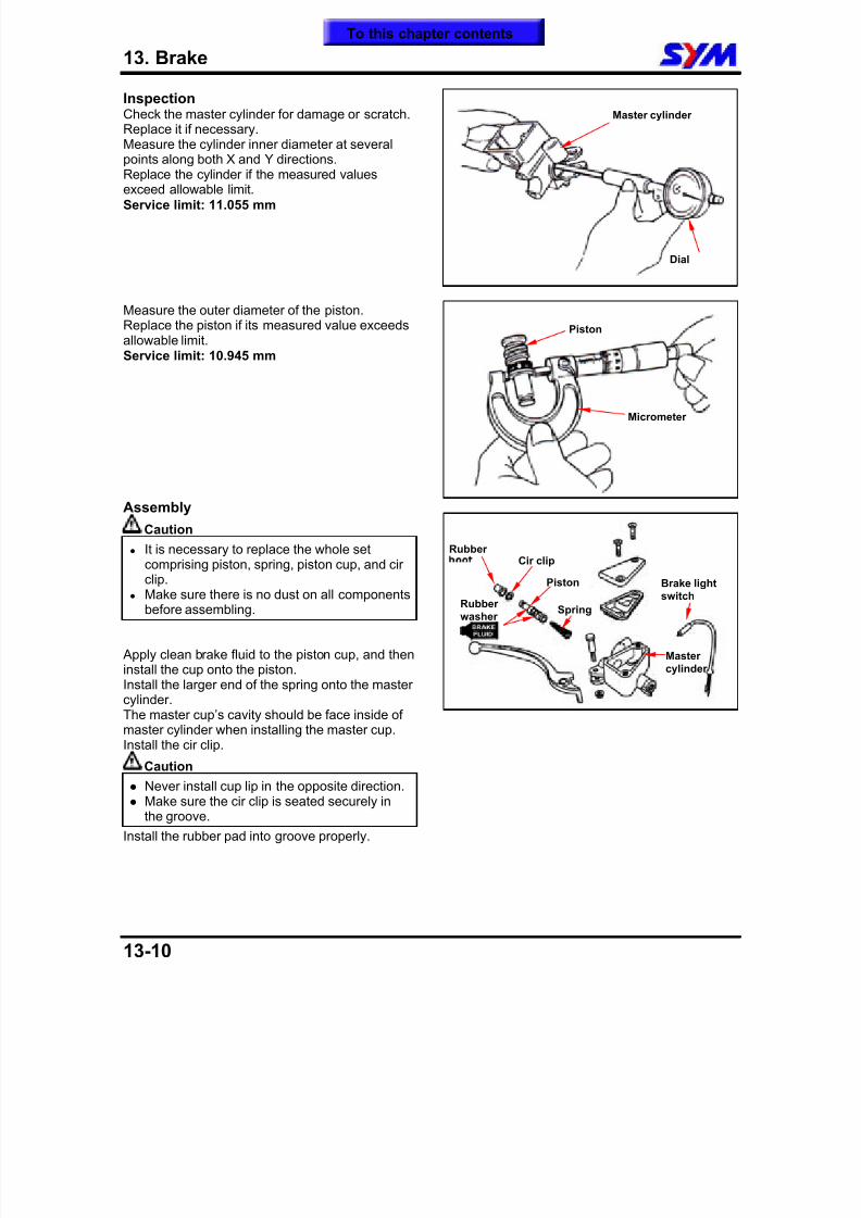
8/12/2019 SYM Mio50 Service Manual 000
http://slidepdf.com/reader/full/sym-mio50-service-manual-000 159/215
13. Brake
13-10
Inspection Check the master cylinder for damage or scratch.Replace it if necessary.Measure the cylinder inner diameter at severalpoints along both X and Y directions.
Replace the cylinder if the measured valuesexceed allowable limit.Service limit: 11.055 mm
Measure the outer diameter of the piston.Replace the piston if its measured value exceedsallowable limit.
Service limit: 10.945 mm
Assembly
Caution It is necessary to replace the whole set
comprising piston, spring, piston cup, and circlip.
Make sure there is no dust on all componentsbefore assembling.
Apply clean brake fluid to the piston cup, and theninstall the cup onto the piston.Install the larger end of the spring onto the mastercylinder.The master cup’s cavity should be face inside ofmaster cylinder when installing the master cup.Install the cir clip.
Caution Never install cup lip in the opposite direction. Make sure the cir clip is seated securely in
the groove. Install the rubber pad into groove properly.
Master cylinder
Dial
Piston
Micrometer
Cir clip
Piston
Rubberwasher
Rubber
Brake lightswitch
Mastercylinder
Spring
To this chapter contents
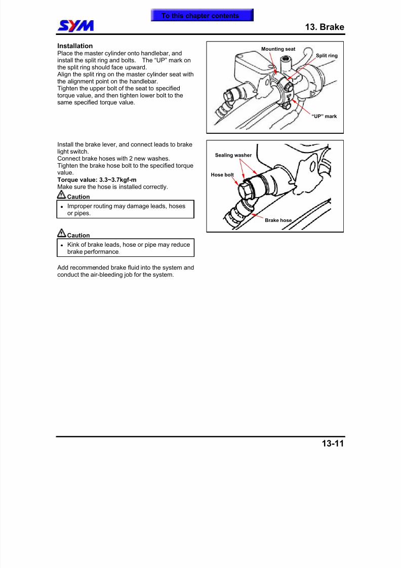
8/12/2019 SYM Mio50 Service Manual 000
http://slidepdf.com/reader/full/sym-mio50-service-manual-000 160/215
13. Brake
13-11
InstallationPlace the master cylinder onto handlebar, andinstall the split ring and bolts. The “UP” mark onthe split ring should face upward. Align the split ring on the master cylinder seat with
the alignment point on the handlebar.Tighten the upper bolt of the seat to specifiedtorque value, and then tighten lower bolt to thesame specified torque value.
Install the brake lever, and connect leads to brakelight switch.Connect brake hoses with 2 new washes.
Tighten the brake hose bolt to the specified torquevalue.Torque value: 3.3~3.7kgf-mMake sure the hose is installed correctly.
Caution
Improper routing may damage leads, hosesor pipes.
Caution
Kink of brake leads, hose or pipe may reducebrake performance.
Add recommended brake fluid into the system andconduct the air-bleeding job for the system.
Split ring
Mounting seat
“UP” mark
Brake hose
Sealing washer
Hose bolt
To this chapter contents
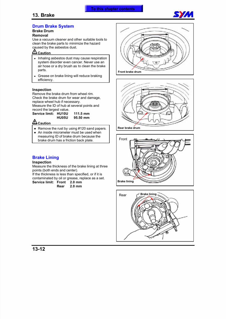
8/12/2019 SYM Mio50 Service Manual 000
http://slidepdf.com/reader/full/sym-mio50-service-manual-000 161/215
13. Brake
13-12
Drum Brake SystemBrake DrumRemovalUse a vacuum cleaner and other suitable tools toclean the brake parts to minimize the hazard
caused by the asbestos dust.
Caution
Inhaling asbestos dust may cause respirationsystem disorder even cancer. Never use anair hose or a dry brush as to clean the brakeparts.
Grease on brake lining will reduce brakingefficiency.
InspectionRemove the brake drum from wheel rim.Check the brake drum for wear and damage,replace wheel hub if necessary.Measure the ID of hub at several points andrecord the largest value.Service limit: HU10U 111.5 mm
HU05U 95.50 mm
Caution
Remove the rust by using #120 sand papers. An inside micrometer must be used when
measuring ID of brake drum because the
brake drum has a friction back plate.
Brake LiningInspectionMeasure the thickness of the brake lining at threepoints (both ends and center).If the thickness is less than specified, or if it iscontaminated by oil or grease, replace as a set.Service limit: Front 2.0 mm
Rear 2.0 mm
Front
Rear
Front brake drum
Brake lining
Brake lining
Rear brake drum
To this chapter contents
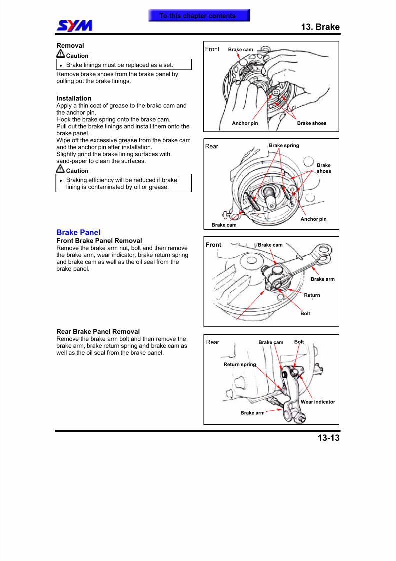
8/12/2019 SYM Mio50 Service Manual 000
http://slidepdf.com/reader/full/sym-mio50-service-manual-000 162/215
13. Brake
13-13
Removal
Caution
Brake linings must be replaced as a set. Remove brake shoes from the brake panel by
pulling out the brake linings.
Installation Apply a thin coat of grease to the brake cam andthe anchor pin.Hook the brake spring onto the brake cam.Pull out the brake linings and install them onto thebrake panel.Wipe off the excessive grease from the brake camand the anchor pin after installation.Slightly grind the brake lining surfaces with
sand-paper to clean the surfaces.Caution
Braking efficiency will be reduced if brakelining is contaminated by oil or grease.
Brake PanelFront Brake Panel RemovalRemove the brake arm nut, bolt and then removethe brake arm, wear indicator, brake return springand brake cam as well as the oil seal from thebrake panel.
Rear Brake Panel RemovalRemove the brake arm bolt and then remove thebrake arm, brake return spring and brake cam aswell as the oil seal from the brake panel.
Bolt
Brake arm
Return
Brake cam
Front
Brakeshoes
Brake camAnchor pin
Rear
Front
Anchor pin
Brake spring
Brake cam
Brake shoes
Bolt
Brake arm
Return spring
Wear indicator
Brake camRear
To this chapter contents
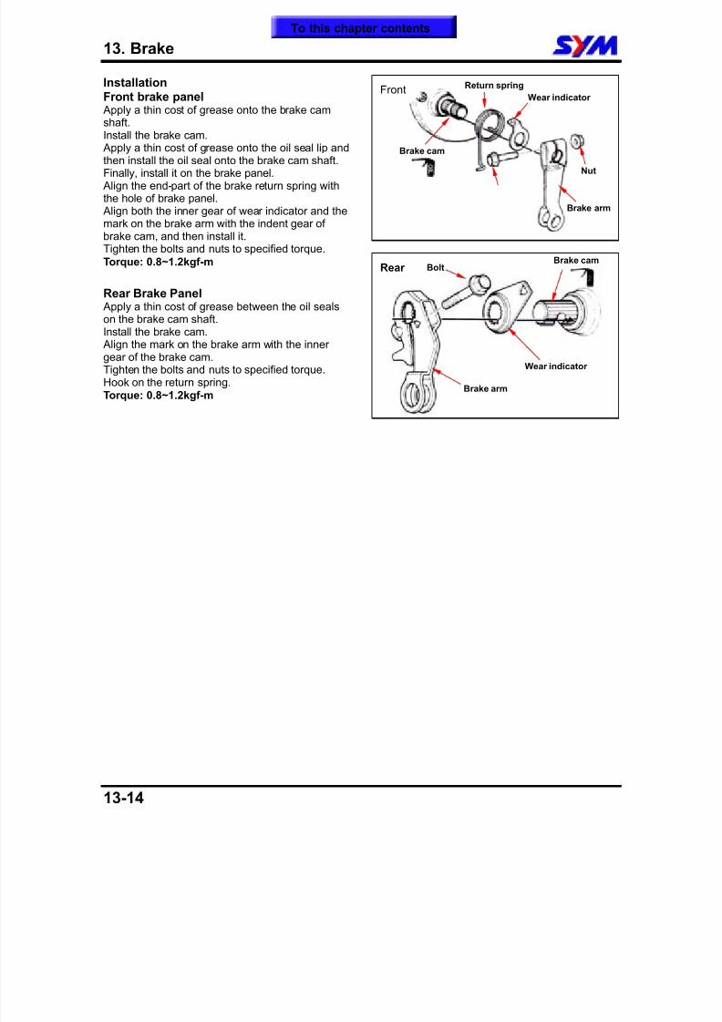
8/12/2019 SYM Mio50 Service Manual 000
http://slidepdf.com/reader/full/sym-mio50-service-manual-000 163/215
13. Brake
13-14
InstallationFront brake panel Apply a thin cost of grease onto the brake camshaft.Install the brake cam.
Apply a thin cost of grease onto the oil seal lip andthen install the oil seal onto the brake cam shaft.Finally, install it on the brake panel. Align the end-part of the brake return spring withthe hole of brake panel. Align both the inner gear of wear indicator and themark on the brake arm with the indent gear ofbrake cam, and then install it.Tighten the bolts and nuts to specified torque.Torque: 0.8~1.2kgf-m
Rear Brake Panel Apply a thin cost of grease between the oil sealson the brake cam shaft.Install the brake cam. Align the mark on the brake arm with the innergear of the brake cam.Tighten the bolts and nuts to specified torque.Hook on the return spring.Torque: 0.8~1.2kgf-m
Brake arm
Return spring
Wear indicator
Brake cam
Front
Bolt
Brake arm
Wear indicator
Brake camRear
Nut
To this chapter contents
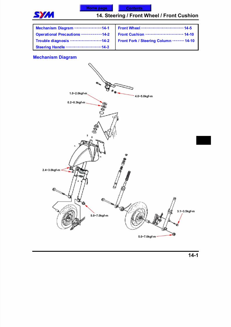
8/12/2019 SYM Mio50 Service Manual 000
http://slidepdf.com/reader/full/sym-mio50-service-manual-000 164/215
14. Steering / Front Wheel / Front Cushion
14-1
Mechanism Diagram ··························14-1
Operational Precautions····················14-2
Trouble diagnosis ······························14-2
Steering Handle ··································14-3
Front Wheel ········································ 14-5
Front Cushion ···································· 14-10
Front Fork / Steering Column ··········· 14-10
Mechanism Diagram
3.1~3.5kgf-m
1.0~2.0kgf-m
5.0~7.0kgf-m
0.2~0.3kgf-m
4.0~5.0kgf-m
5.0~7.0kgf-m
2.4~3.0kgf-m
14
Home page Contents
8/12/2019 SYM Mio50 Service Manual 000
http://slidepdf.com/reader/full/sym-mio50-service-manual-000 165/215
14. Steering / Front Wheel / Front Cushion
14-2
Operational PrecautionsGeneral information Before remove front wheel, use a jack to lift the body until front wheel free of ground, and take care not
to rotate body in reverse. Be careful not to allow oil or grease get on brake drum, disk or linings.
Torque valuesFront wheel axle nut 5.0~7.0kgf-mSteering handle nut 4.0~5.0kgf-mSteering column top cone sliding ring 0.2~0.3kgf-mSteering column lock nut 1.0~2.0kgf-mSpeedometer cable screw 0.15~0.3kgf-mFront cushion: Upper nut 2.4~3.0kgf-mFront brake caliper bolt 3.1~3.5kgf-m
Special service toolsSteering column wrenchBearing removerInner type bearing remover SYM-6204002 Attachment, 32×35 mm Attachment, 42×47 mmSteering column nut wrenchSteering column top cone ring nut wrench
Trouble diagnosisHard steering stem Over tightening of steering stem lock nut
Broken steering stem steel ball Damaged steering stem steel ball Insufficient tire pressure
Steering stem off center Uneven left/right cushion Bend fork Bent front wheel/tire offset
Front wheel wobbling Deformed rim
Front wheel bearing loose Faulty tire Wheel axle nut tightened improperly
Soft front suspension
Weak fork springs Cushion seal leaking
Front suspension noise Cushion cover friction noise Cushion bolts loose
To this chapter contents
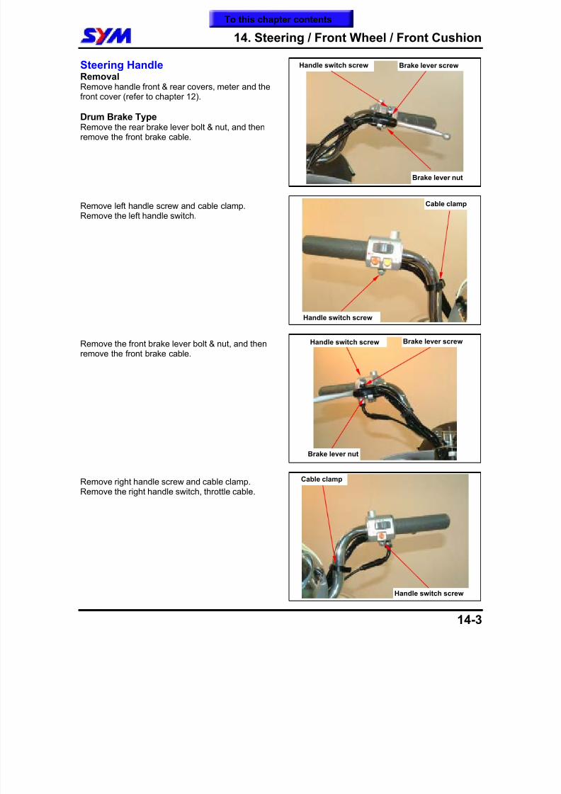
8/12/2019 SYM Mio50 Service Manual 000
http://slidepdf.com/reader/full/sym-mio50-service-manual-000 166/215
14. Steering / Front Wheel / Front Cushion
14-3
Steering HandleRemovalRemove handle front & rear covers, meter and thefront cover (refer to chapter 12).
Drum Brake TypeRemove the rear brake lever bolt & nut, and thenremove the front brake cable.
Remove left handle screw and cable clamp.Remove the left handle switch.
Remove the front brake lever bolt & nut, and thenremove the front brake cable.
Remove right handle screw and cable clamp.Remove the right handle switch, throttle cable.
Brake lever screw
Brake lever nut
Handle switch screw
Handle switch screw
Cable clamp
Handle switch screw Brake lever screw
Brake lever nut
Handle switch screw
Cable clamp
To this chapter contents
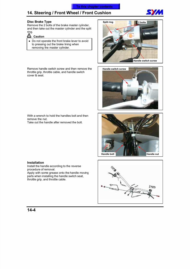
8/12/2019 SYM Mio50 Service Manual 000
http://slidepdf.com/reader/full/sym-mio50-service-manual-000 167/215
14. Steering / Front Wheel / Front Cushion
14-4
Disc Brake TypeRemove the 2 bolts of the brake master cylinder,and then take out the master cylinder and the splitring.
Caution
Do not operate the front brake lever to avoidto pressing out the brake lining whenremoving the master cylinder.
Remove handle switch screw and then remove thethrottle grip, throttle cable, and handle switchcover & seat.
With a wrench to hold the handles bolt and thenremove the nut.Take out the handle after removed the bolt.
InstallationInstall the handle according to the reverseprocedure of removal. Apply with some grease onto the handle movingparts when installing the handle switch seat,throttle grip, and throttle cable.
Split ring 2 bolts
Handle bolt Handle nut
Handle switch screw
Handle switch screw
To this chapter contents
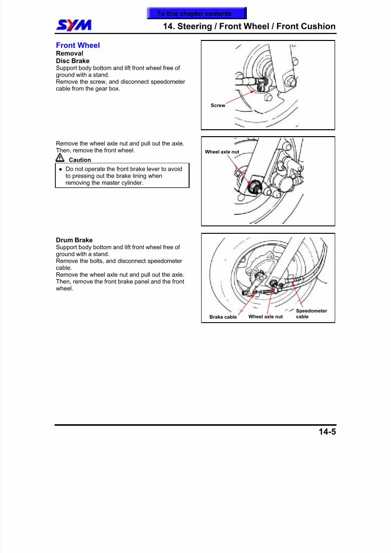
8/12/2019 SYM Mio50 Service Manual 000
http://slidepdf.com/reader/full/sym-mio50-service-manual-000 168/215
14. Steering / Front Wheel / Front Cushion
14-5
Front WheelRemovalDisc BrakeSupport body bottom and lift front wheel free ofground with a stand.
Remove the screw, and disconnect speedometercable from the gear box.
Remove the wheel axle nut and pull out the axle.Then, remove the front wheel.
Caution Do not operate the front brake lever to avoid
to pressing out the brake lining whenremoving the master cylinder.
Drum BrakeSupport body bottom and lift front wheel free ofground with a stand.Remove the bolts, and disconnect speedometercable.Remove the wheel axle nut and pull out the axle.Then, remove the front brake panel and the frontwheel.
Wheel axle nut
Screw
Brake cable Wheel axle nutSpeedometer cable
To this chapter contents
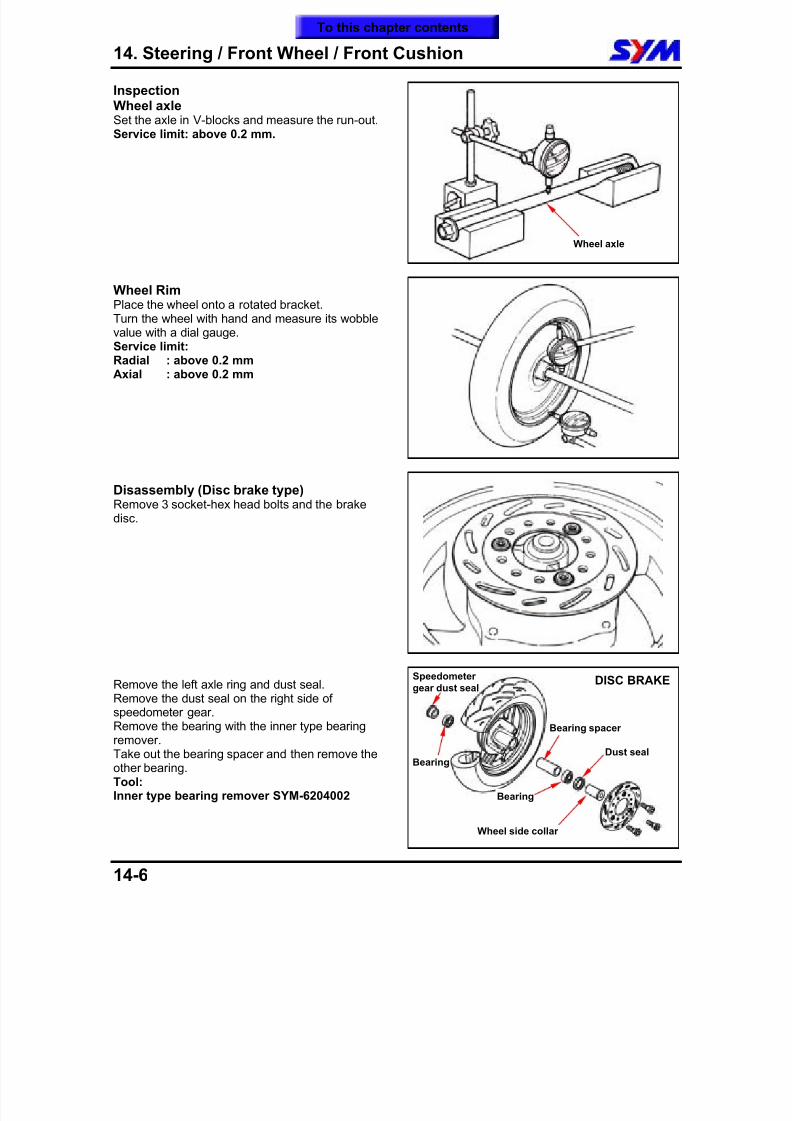
8/12/2019 SYM Mio50 Service Manual 000
http://slidepdf.com/reader/full/sym-mio50-service-manual-000 169/215
14. Steering / Front Wheel / Front Cushion
14-6
InspectionWheel axleSet the axle in V-blocks and measure the run-out.Service limit: above 0.2 mm.
Wheel RimPlace the wheel onto a rotated bracket.Turn the wheel with hand and measure its wobblevalue with a dial gauge.Service limit:Radial : above 0.2 mmAxial : above 0.2 mm
Disassembly (Disc brake type)Remove 3 socket-hex head bolts and the brakedisc.
Remove the left axle ring and dust seal.Remove the dust seal on the right side ofspeedometer gear. Remove the bearing with the inner type bearingremover.Take out the bearing spacer and then remove theother bearing.Tool:Inner type bearing remover SYM-6204002
Speedometer gear dust seal
Wheel axle
Dust seal
Wheel side collar
Bearing
Bearing spacer
DISC BRAKE
Bearing
To this chapter contents
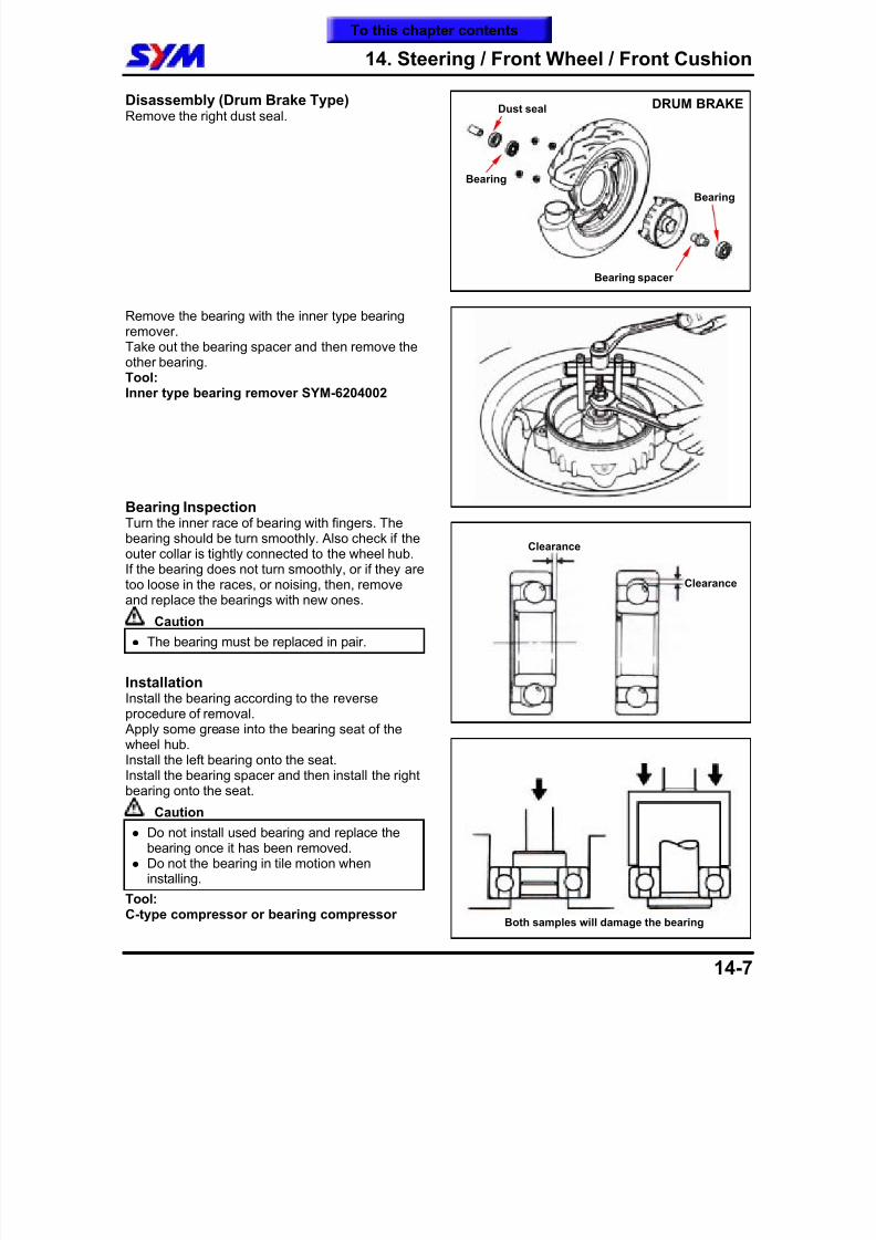
8/12/2019 SYM Mio50 Service Manual 000
http://slidepdf.com/reader/full/sym-mio50-service-manual-000 170/215
14. Steering / Front Wheel / Front Cushion
14-7
Disassembly (Drum Brake Type)Remove the right dust seal.
Remove the bearing with the inner type bearingremover.Take out the bearing spacer and then remove the
other bearing.Tool:Inner type bearing remover SYM-6204002
Bearing InspectionTurn the inner race of bearing with fingers. The
bearing should be turn smoothly. Also check if theouter collar is tightly connected to the wheel hub.If the bearing does not turn smoothly, or if they aretoo loose in the races, or noising, then, removeand replace the bearings with new ones.
Caution The bearing must be replaced in pair.
InstallationInstall the bearing according to the reverseprocedure of removal. Apply some grease into the bearing seat of thewheel hub.Install the left bearing onto the seat.Install the bearing spacer and then install the rightbearing onto the seat.
Caution
Do not install used bearing and replace thebearing once it has been removed.
Do not the bearing in tile motion wheninstalling.
Tool:C-type compressor or bearing compressor
Clearance
Clearance
Bearing spacer
DRUM BRAKE
Bearing
Dust seal
Bearing
Both samples will damage the bearing
To this chapter contents
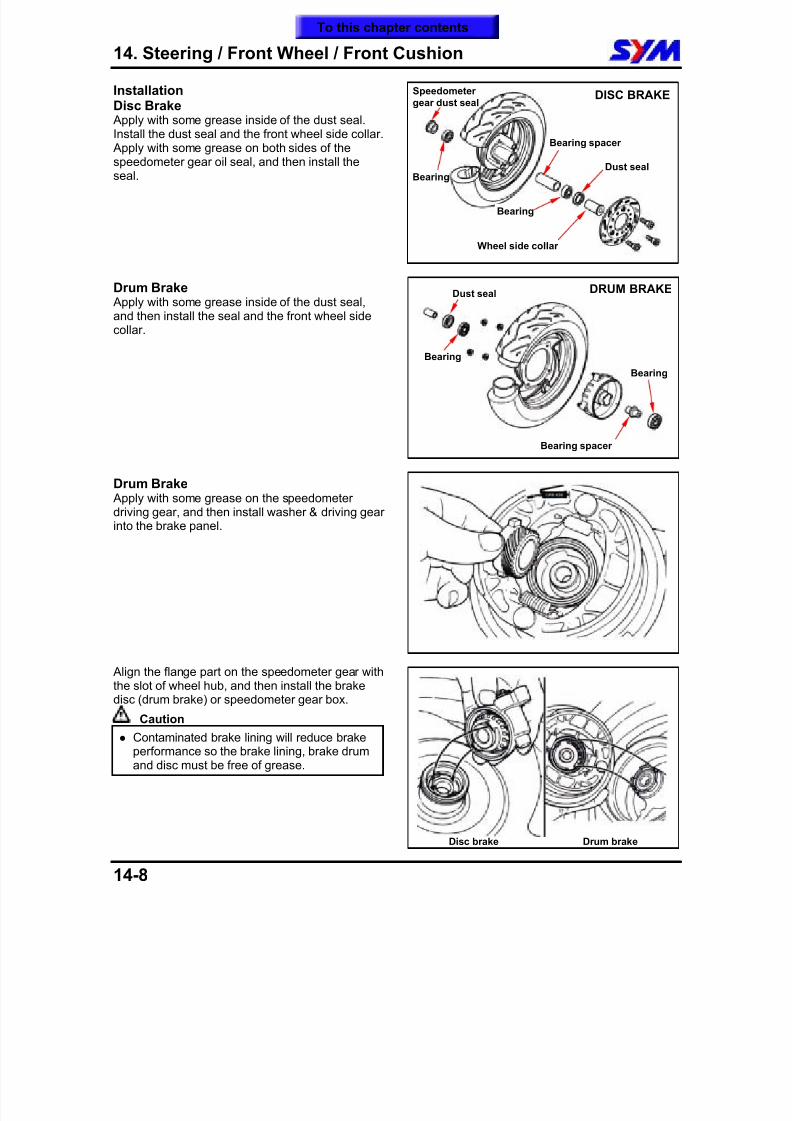
8/12/2019 SYM Mio50 Service Manual 000
http://slidepdf.com/reader/full/sym-mio50-service-manual-000 171/215
14. Steering / Front Wheel / Front Cushion
14-8
InstallationDisc Brake Apply with some grease inside of the dust seal.Install the dust seal and the front wheel side collar. Apply with some grease on both sides of the
speedometer gear oil seal, and then install theseal.
Drum Brake Apply with some grease inside of the dust seal,and then install the seal and the front wheel side
collar.
Drum Brake Apply with some grease on the speedometerdriving gear, and then install washer & driving gearinto the brake panel.
Align the flange part on the speedometer gear withthe slot of wheel hub, and then install the brakedisc (drum brake) or speedometer gear box.
Caution
Contaminated brake lining will reduce brakeperformance so the brake lining, brake drumand disc must be free of grease.
Disc brake Drum brake
Speedometer gear dust seal
Dust seal
Wheel side collar
Bearing
Bearing spacer
DISC BRAKE
Bearing
Bearing spacer
DRUM BRAKE
Bearing
Dust seal
Bearing
To this chapter contents
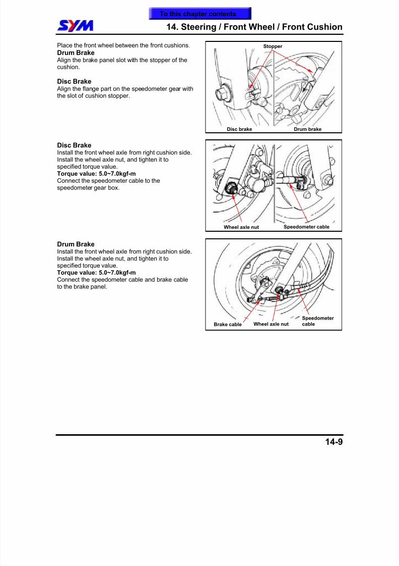
8/12/2019 SYM Mio50 Service Manual 000
http://slidepdf.com/reader/full/sym-mio50-service-manual-000 172/215
14. Steering / Front Wheel / Front Cushion
14-9
Place the front wheel between the front cushions.
Drum Brake Align the brake panel slot with the stopper of thecushion.
Disc Brake Align the flange part on the speedometer gear withthe slot of cushion stopper.
Disc BrakeInstall the front wheel axle from right cushion side.Install the wheel axle nut, and tighten it to
specified torque value.Torque value: 5.0~7.0kgf-mConnect the speedometer cable to thespeedometer gear box.
Drum BrakeInstall the front wheel axle from right cushion side.Install the wheel axle nut, and tighten it tospecified torque value.Torque value: 5.0~7.0kgf-mConnect the speedometer cable and brake cableto the brake panel.
Speedometer cableWheel axle nut
Stopper
Disc brake Drum brake
Brake cable Wheel axle nutSpeedometer cable
To this chapter contents
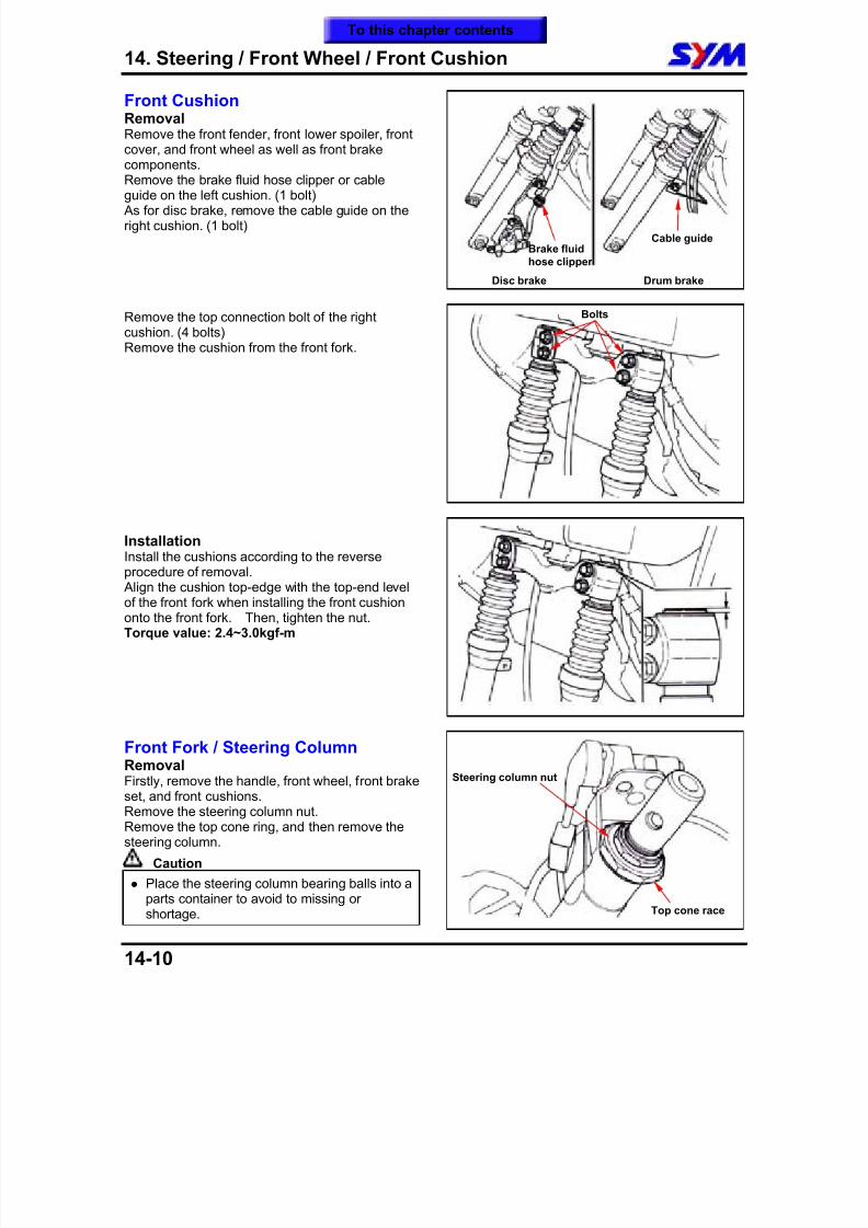
8/12/2019 SYM Mio50 Service Manual 000
http://slidepdf.com/reader/full/sym-mio50-service-manual-000 173/215
14. Steering / Front Wheel / Front Cushion
14-10
Front CushionRemovalRemove the front fender, front lower spoiler, frontcover, and front wheel as well as front brakecomponents.
Remove the brake fluid hose clipper or cableguide on the left cushion. (1 bolt) As for disc brake, remove the cable guide on theright cushion. (1 bolt)
Remove the top connection bolt of the rightcushion. (4 bolts)Remove the cushion from the front fork.
InstallationInstall the cushions according to the reverseprocedure of removal. Align the cushion top-edge with the top-end levelof the front fork when installing the front cushiononto the front fork. Then, tighten the nut.Torque value: 2.4~3.0kgf-m
Front Fork / Steering ColumnRemovalFirstly, remove the handle, front wheel, front brakeset, and front cushions.Remove the steering column nut.Remove the top cone ring, and then remove thesteering column.
Caution Place the steering column bearing balls into a
parts container to avoid to missing orshortage.
Brake fluidhose clipper
Cable guide
Disc brake
Bolts
Drum brake
Steering column nut
Top cone race
To this chapter contents
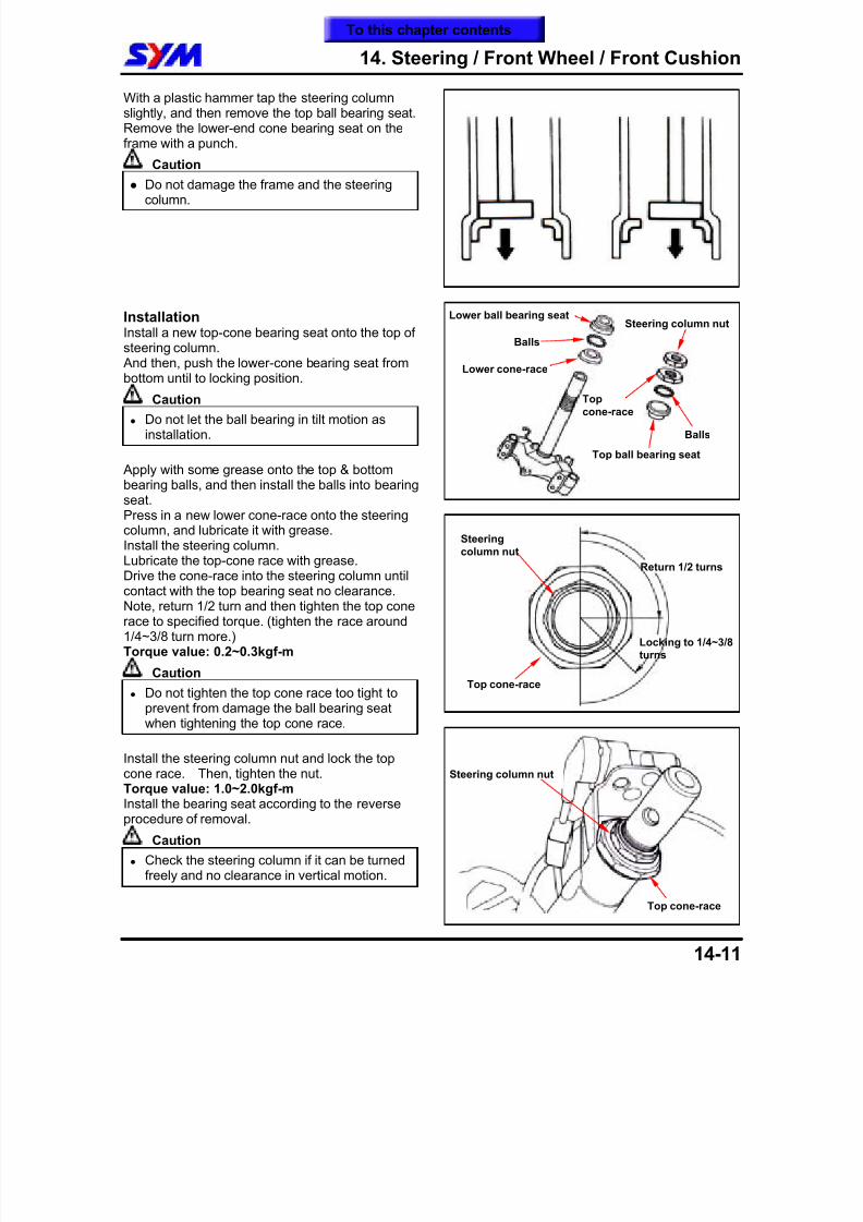
8/12/2019 SYM Mio50 Service Manual 000
http://slidepdf.com/reader/full/sym-mio50-service-manual-000 174/215

8/12/2019 SYM Mio50 Service Manual 000
http://slidepdf.com/reader/full/sym-mio50-service-manual-000 175/215
14. Steering / Front Wheel / Front Cushion
14-12
Note:
To this chapter contents
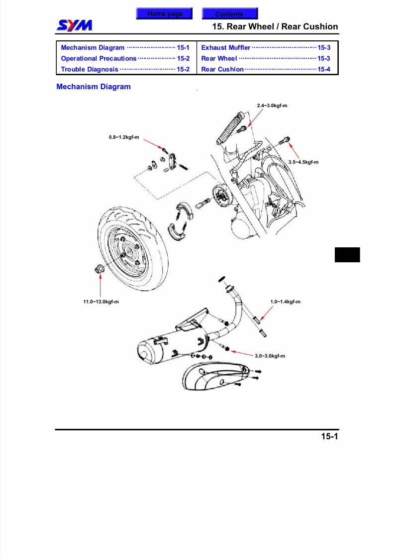
8/12/2019 SYM Mio50 Service Manual 000
http://slidepdf.com/reader/full/sym-mio50-service-manual-000 176/215
15. Rear Wheel / Rear Cushion
15-1
Mechanism Diagram ··························· 15-1
Operational Precautions····················· 15-2
Trouble Diagnosis ······························· 15-2
Exhaust Muffler ····································15-3
Rear Wheel ···········································15-3
Rear Cushion········································15-4
Mechanism Diagram
15
11.0~13.0kgf-m
3.0~3.6kgf-m
1.0~1.4kgf-m
0.8~1.2kgf-m
2.4~3.0kgf-m
3.5~4.5kgf-m
Home page Contents
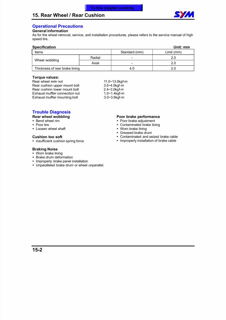
8/12/2019 SYM Mio50 Service Manual 000
http://slidepdf.com/reader/full/sym-mio50-service-manual-000 177/215
15. Rear Wheel / Rear Cushion
15-2
Operational PrecautionsGeneral information As for the wheel removal, service, and installation procedures, please refers to the service manual of highspeed tire.
Specification Unit: mmItems Standard (mm) Limit (mm)
Radial - 2.0Wheel wobbling
Axial - 2.0
Thickness of rear brake lining 4.0 2.0
Torque values:Rear wheel axle nut 11.0~13.0kgf-mRear cushion upper mount bolt 3.5~4.5kgf-mRear cushion lower mount bolt 2.4~3.0kgf-m
Exhaust muffler connection nut 1.0~1.4kgf-mExhaust muffler mounting bolt 3.0~3.6kgf-m
Trouble DiagnosisRear wheel wobbling Bend wheel rim Poor tire Loosen wheel shaft
Cushion too soft insufficient cushion spring force
Braking Noise Worn brake lining Brake drum deformation Improperly brake panel installation Unparalleled brake drum or wheel unparallel.
Poor brake performance Poor brake adjustment Contaminated brake lining Worn brake lining Greased brake drum Contaminated and seized brake cable Improperly installation of brake cable
To this chapter contents
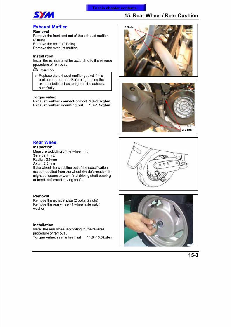
8/12/2019 SYM Mio50 Service Manual 000
http://slidepdf.com/reader/full/sym-mio50-service-manual-000 178/215
15. Rear Wheel / Rear Cushion
15-3
Exhaust MufflerRemoval Remove the front-end nut of the exhaust muffler.(2 nuts)Remove the bolts. (2 bolts)
Remove the exhaust muffler.
InstallationInstall the exhaust muffler according to the reverseprocedure of removal.
Caution
Replace the exhaust muffler gasket if it isbroken or deformed. Before tightening theexhaust bolts, it has to tighten the exhaustnuts firstly.
Torque value:Exhaust muffler connection bolt 3.0~3.6kgf-mExhaust muffler mounting nut 1.0~1.4kgf-m
Rear WheelInspectionMeasure wobbling of the wheel rim.Service limit:Radial: 2.0mmAxial: 2.0mmIf the wheel rim wobbling out of the specification,except resulted from the wheel rim deformation, itmight be loosen or worn final driving shaft bearingor bend, deformed driving shaft.
RemovalRemove the exhaust pipe (2 bolts, 2 nuts)Remove the rear wheel (1 wheel axle nut, 1washer)
InstallationInstall the rear wheel according to the reverseprocedure of removal.
Torque value: rear wheel nut 11.0~13.0kgf-m
2 Nuts
2 Bolts
To this chapter contents
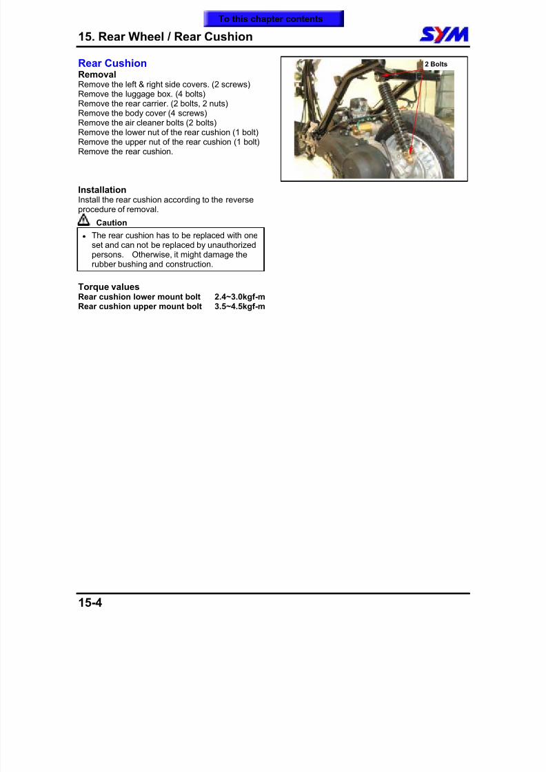
8/12/2019 SYM Mio50 Service Manual 000
http://slidepdf.com/reader/full/sym-mio50-service-manual-000 179/215
15. Rear Wheel / Rear Cushion
15-4
Rear CushionRemovalRemove the left & right side covers. (2 screws)Remove the luggage box. (4 bolts)Remove the rear carrier. (2 bolts, 2 nuts)
Remove the body cover (4 screws)Remove the air cleaner bolts (2 bolts)Remove the lower nut of the rear cushion (1 bolt)Remove the upper nut of the rear cushion (1 bolt)Remove the rear cushion.
InstallationInstall the rear cushion according to the reverseprocedure of removal.
Caution The rear cushion has to be replaced with one
set and can not be replaced by unauthorizedpersons. Otherwise, it might damage therubber bushing and construction.
Torque valuesRear cushion lower mount bolt 2.4~3.0kgf-mRear cushion upper mount bolt 3.5~4.5kgf-m
2 Bolts
To this chapter contents
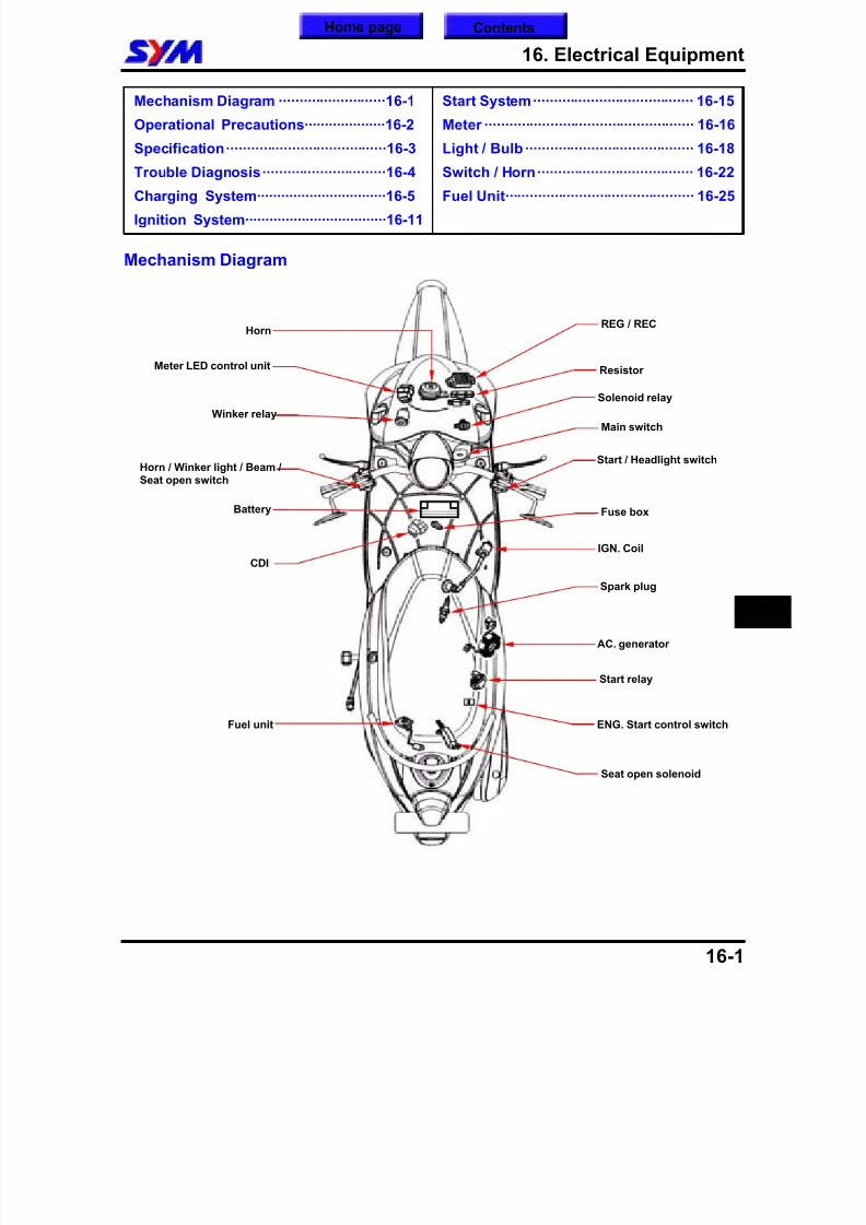
8/12/2019 SYM Mio50 Service Manual 000
http://slidepdf.com/reader/full/sym-mio50-service-manual-000 180/215
16. Electrical Equipment
16-1
Mechanism Diagram ··························16-1
Operational Precautions····················16-2
Specification·······································16-3
Trouble Diagnosis······························16-4
Charging System································16-5
Ignition System···································16-11
Start System······································· 16-15
Meter ··················································· 16-16
Light / Bulb ········································· 16-18
Switch / Horn······································ 16-22
Fuel Unit·············································· 16-25
Mechanism Diagram
16
IGN. Coil
Spark plug
Main switch
Resistor
Start / Headlight switch
AC. generator
Fuse box
Winker relay
Horn / Winker light / Beam /Seat open switch
REG / RECHorn
Seat open solenoid
CDI
Fuel unit
Start relay
Battery
Meter LED control unit
Solenoid relay
ENG. Start control switch
Home page Contents
8/12/2019 SYM Mio50 Service Manual 000
http://slidepdf.com/reader/full/sym-mio50-service-manual-000 181/215
16. Electrical Equipment
16-2
Operational PrecautionsCharging System When remove the battery, the disconnection sequence of cable terminals shall be strictly observed.
(First disconnect the negative cable terminal, next, the positive cable terminal.) MF (Maintenance Free) battery does not need to check, add electrolyte or distilled water.
Battery must be taken out from scooter when charging the battery. But do not open the battery caps. Do not quick charge the battery unless in emergency. A voltmeter must be used when checking battery charging condition. Battery can be charged or discharged alternately. To set a discharged battery idle for a prolonged
period will shorten its service life and reduce its capacity. Usually, battery’s capacity will reduce after1~2 years. After low capacity battery was charged, its voltage will increase. If it connects to anadditional load, the voltage will reduce suddenly, and then go up again.
Over-charged battery. Usually, the over-charged battery can be seen externally. If a short circuitoccurred inside the battery, there will be no voltage on the terminals of battery if voltage regulator doesnot operate. Then, the battery’s voltage will be too high that may reduce battery’s life.
The battery will be self-discharged if it was set idle for a long time. An idle battery must be chargedabout every 2months.
A new battery filled with electrolyte will generate a voltage after filled out electrolyte. The voltage shouldbe in 12.5V or more after 10 minutes. When electrolyte is not enough, the battery must be filled withelectrolyte and then charged to prolong the battery’s life-span.
Please check electrical device according to the procedure of diagnosis chart. Do not disconnect and connect the coupler of electrical devices when current is passing these devices
because this will generate high voltage and the electrical components in the voltage-current regulatorwill be damaged. The ignition switch must be turned OFF before performing any work.
Please do not replace with traditional type battery as replacement. Please refer to the removal instruction when removing the alternator and the pulse generator.
Ignition System Please follow the procedure of trouble diagnosis chart to check ignition system. The ignition system equipped with a auto-advanced timing device in CDI unit. Thus, ignition timing need
not to be adjusted. In case of incorrect ignition timing occurred, check the CDI unit or alternator system.It has to check the ignition timing with the ignition timing lamp if replaced these components.
Do not hang or impact the CDI unit of ignition system because the major faulty of CDI unit is caused byimpact. Therefore, take care when disassembling.
Most of ignition system problems were resulted from poor connecting coupler. Please check thecouplers first when servicing.
Make sure that the heat range of spark plug is suitable. Improper spark plug is the main cause of poorengine operation or combustion.
Inspection procedures in this manual are based on Max. voltage. This manual also contains methods of
how to check ignition coil resistance and component operation. Please follow the continuity chart to check ignition switch.
Starting System As to the ignition system inspection, please follow the Trouble Diagnosis procedure to check. Starting motor can be removed directly from engine. Please refer to chapter 10 for starting clutch removal procedures.
To this chapter contents
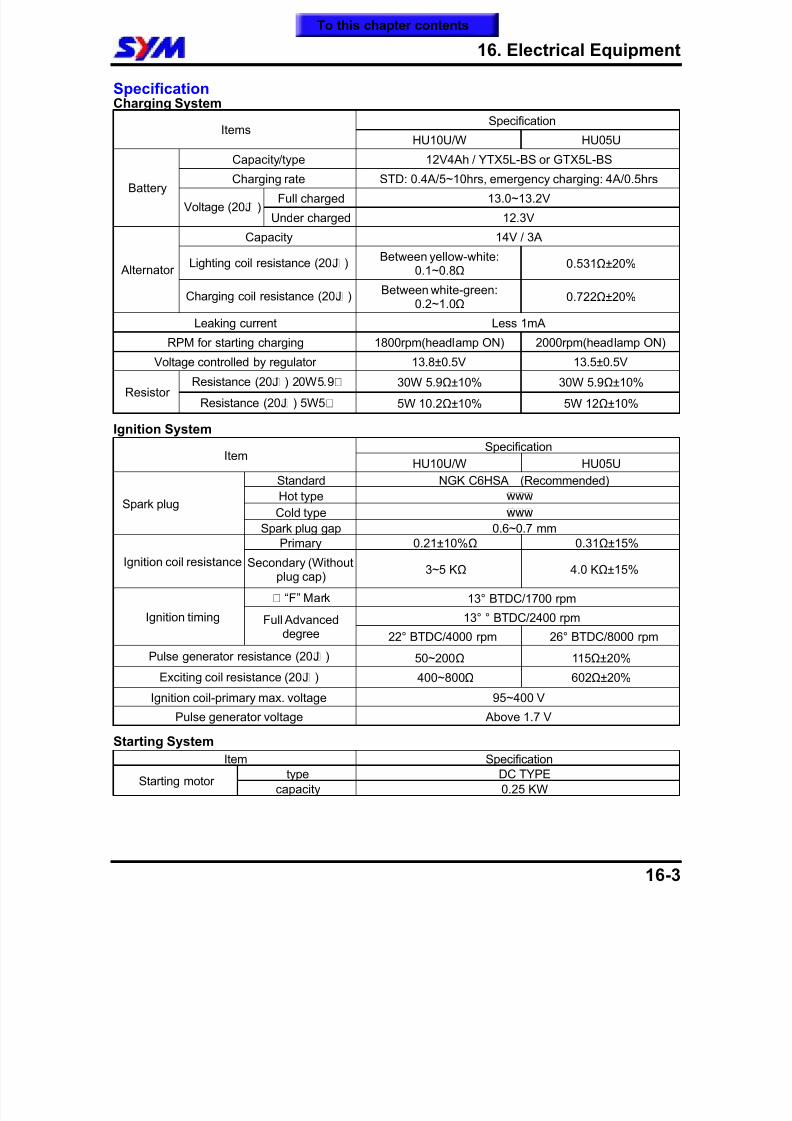
8/12/2019 SYM Mio50 Service Manual 000
http://slidepdf.com/reader/full/sym-mio50-service-manual-000 182/215
16. Electrical Equipment
16-3
SpecificationCharging System
SpecificationItems
HU10U/W HU05U
Capacity/type 12V4Ah / YTX5L-BS or GTX5L-BSCharging rate STD: 0.4A/5~10hrs, emergency charging: 4A/0.5hrs
Full charged 13.0~13.2VBattery
Voltage (20¢J )Under charged 12.3V
Capacity 14V / 3A
Lighting coil resistance (20¢J )Between yellow-white:
0.1~0.8Ω 0.531Ω±20%
Alternator
Charging coil resistance (20¢J )Between white-green:
0.2~1.0Ω 0.722Ω±20%
Leaking current Less 1mARPM for starting charging 1800rpm(headlamp ON) 2000rpm(headlamp ON)
Voltage controlled by regulator 13.8±0.5V 13.5±0.5V
Resistance (20¢J ) 20W5.9£[ 30W 5.9Ω±10% 30W 5.9Ω±10%Resistor
Resistance (20¢J ) 5W5£[ 5W 10.2Ω±10% 5W 12Ω±10%
Ignition System
SpecificationItem
HU10U/W HU05U
Standard NGK C6HSA (Recommended)
Hot type ¢w¢w¢w
Cold type ¢w¢w¢wSpark plug
Spark plug gap 0.6~0.7 mm
Primary 0.21±10%Ω 0.31Ω±15%
Ignition coil resistance Secondary (Withoutplug cap)
3~5 KΩ 4.0 KΩ±15%
¡© “F” Mark 13° BTDC/1700 rpm
13° ° BTDC/2400 rpmIgnition timing Full Advanceddegree 22° BTDC/4000 rpm 26° BTDC/8000 rpm
Pulse generator resistance (20¢J ) 50~200Ω 115Ω±20%
Exciting coil resistance (20¢J ) 400~800Ω 602Ω±20%
Ignition coil-primary max. voltage 95~400 V
Pulse generator voltage Above 1.7 V
Starting System
Item Specification
type DC TYPEStarting motor
capacity 0.25 KW
To this chapter contents
8/12/2019 SYM Mio50 Service Manual 000
http://slidepdf.com/reader/full/sym-mio50-service-manual-000 183/215
16. Electrical Equipment
16-4
Trouble DiagnosisCharging SystemNo power supply Dead battery Disconnect battery cable
Fuse burned out Faulty main switch
Low voltage Weak battery Loose battery connection Charging system failure Voltage-current regulator failure
Intermittent power supply Loose charging system cables Loose battery cables Poor connection or shorted circuit in discharging
system Poor connection or shorted circuit in charging
system
Charging system failure The fuse is blown Loose, broken or shorted wire or wire
connection Faulty voltage-current regulator Faulty alternator
Starting System
Starter motor does not work The fuse is blown The battery is not fully charge Poor main switch Poor starter switch The front and rear brake switches do not
operate correctly Starter relay is out of work The ignition coil is poorly connected, open or
short-circuited The starter motor is out of work
Weak starter motor Poor charging system The battery is not fully charged Poor connection in the windings The motor gear is jammed by foreign material
Starter motor is working, but engine does notcrank Poor starter motor pinion Poor starter clutch The starter motor run in reverse direction Poor battery
Ignition SystemNo spark produced by spark plug The spark plug is out of work The cable is poorly connected, open or
short-circuited- Between alternator and C.D.I.- Between CDI and ignition coil.- Between CDI and main switch
Poor main switch Poor C.D.I. alternator is out of work
Engine does not crank smoothly Primary coil circuit
- Poor ignition coil- Poor connection of cable and couplers- Poor main switch
Secondary coil circuit- Poor ignition coil- Poor spark plug- Poor high-tension cable- Current leakage in the spark plug cap
Incorrect ignition timing- Poor alternator- Improper installation of the pulse sensor- Poor C.D.I.
To this chapter contents
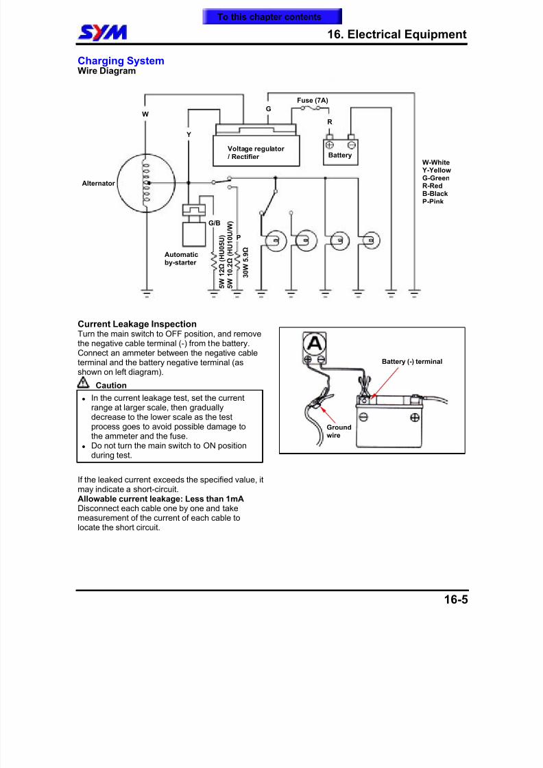
8/12/2019 SYM Mio50 Service Manual 000
http://slidepdf.com/reader/full/sym-mio50-service-manual-000 184/215
16. Electrical Equipment
16-5
Charging SystemWire Diagram
Current Leakage Inspection
Turn the main switch to OFF position, and removethe negative cable terminal (-) from the battery.Connect an ammeter between the negative cableterminal and the battery negative terminal (asshown on left diagram).
Caution
In the current leakage test, set the currentrange at larger scale, then graduallydecrease to the lower scale as the testprocess goes to avoid possible damage tothe ammeter and the fuse.
Do not turn the main switch to ON positionduring test.
If the leaked current exceeds the specified value, itmay indicate a short-circuit.Allowable current leakage: Less than 1mADisconnect each cable one by one and takemeasurement of the current of each cable tolocate the short circuit.
Alternator
Automaticby-starter
Voltage regulator / Rectifier
Fuse (7A)
Battery
G
Y
WR
5 W
1 2 Ω
( H U 0 5 U )
5 W
1 0 . 2
Ω ( H
U 1 0 U / W )
3 0 W
5 . 9
Ω
G/B
P
Battery (-) terminal
Groundwire
W-White Y-YellowG-GreenR-RedB-BlackP-Pink
To this chapter contents
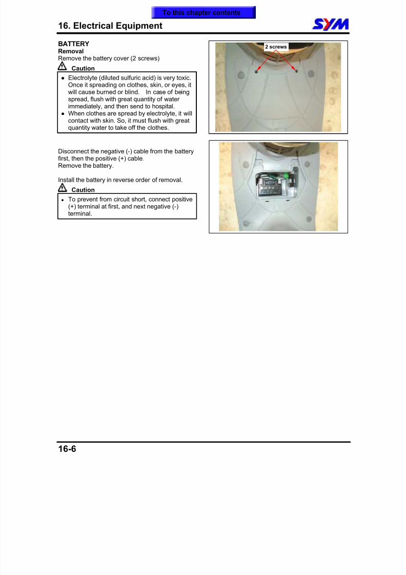
8/12/2019 SYM Mio50 Service Manual 000
http://slidepdf.com/reader/full/sym-mio50-service-manual-000 185/215
16. Electrical Equipment
16-6
BATTERYRemovalRemove the battery cover (2 screws)
Caution
Electrolyte (diluted sulfuric acid) is very toxic.
Once it spreading on clothes, skin, or eyes, itwill cause burned or blind. In case of beingspread, flush with great quantity of waterimmediately, and then send to hospital.
When clothes are spread by electrolyte, it willcontact with skin. So, it must flush with greatquantity water to take off the clothes.
Disconnect the negative (-) cable from the batteryfirst, then the positive (+) cable.
Remove the battery.
Install the battery in reverse order of removal.
Caution
To prevent from circuit short, connect positive(+) terminal at first, and next negative (-)terminal.
2 screws
To this chapter contents
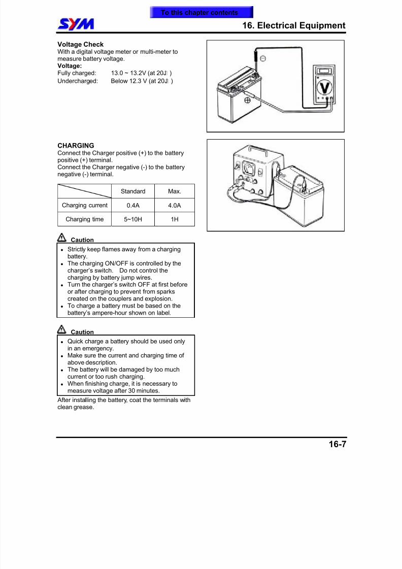
8/12/2019 SYM Mio50 Service Manual 000
http://slidepdf.com/reader/full/sym-mio50-service-manual-000 186/215
16. Electrical Equipment
16-7
Voltage CheckWith a digital voltage meter or multi-meter tomeasure battery voltage.Voltage:Fully charged: 13.0 ~ 13.2V (at 20¢J )
Undercharged: Below 12.3 V (at 20¢J )
CHARGINGConnect the Charger positive (+) to the batterypositive (+) terminal.
Connect the Charger negative (-) to the batterynegative (-) terminal.
Standard Max.
Charging current 0.4A 4.0A
Charging time 5~10H 1H
Caution
Strictly keep flames away from a chargingbattery.
The charging ON/OFF is controlled by thecharger’s switch. Do not control thecharging by battery jump wires.
Turn the charger’s switch OFF at first beforeor after charging to prevent from sparkscreated on the couplers and explosion.
To charge a battery must be based on thebattery’s ampere-hour shown on label.
Caution Quick charge a battery should be used only
in an emergency. Make sure the current and charging time of
above description. The battery will be damaged by too much
current or too rush charging. When finishing charge, it is necessary to
measure voltage after 30 minutes.
After installing the battery, coat the terminals withclean grease.
To this chapter contents
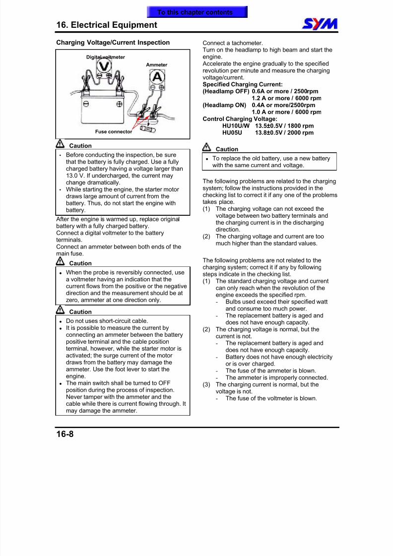
8/12/2019 SYM Mio50 Service Manual 000
http://slidepdf.com/reader/full/sym-mio50-service-manual-000 187/215
16. Electrical Equipment
16-8
Charging Voltage/Current Inspection
Caution Before conducting the inspection, be sure
that the battery is fully charged. Use a fullycharged battery having a voltage larger than13.0 V. If undercharged, the current maychange dramatically.
While starting the engine, the starter motordraws large amount of current from thebattery. Thus, do not start the engine withbattery.
After the engine is warmed up, replace originalbattery with a fully charged battery.Connect a digital voltmeter to the battery
terminals.Connect an ammeter between both ends of themain fuse.
Caution
When the probe is reversibly connected, usea voltmeter having an indication that thecurrent flows from the positive or the negativedirection and the measurement should be atzero, ammeter at one direction only.
Caution
Do not uses short-circuit cable. It is possible to measure the current byconnecting an ammeter between the batterypositive terminal and the cable positionterminal, however, while the starter motor isactivated; the surge current of the motordraws from the battery may damage theammeter. Use the foot lever to start theengine.
The main switch shall be turned to OFFposition during the process of inspection.Never tamper with the ammeter and the
cable while there is current flowing through. Itmay damage the ammeter.
Connect a tachometer.Turn on the headlamp to high beam and start theengine. Accelerate the engine gradually to the specifiedrevolution per minute and measure the chargingvoltage/current.Specified Charging Current:(Headlamp OFF) 0.6A or more / 2500rpm
1.2 A or more / 6000 rpm(Headlamp ON) 0.4A or more/2500rpm
1.0 A or more / 6000 rpmControl Charging Voltage:
HU10U/W 13.5±0.5V / 1800 rpmHU05U 13.8±0.5V / 2000 rpm
Caution
To replace the old battery, use a new batterywith the same current and voltage.
The following problems are related to the chargingsystem; follow the instructions provided in thechecking list to correct it if any one of the problemstakes place.(1) The charging voltage can not exceed the
voltage between two battery terminals andthe charging current is in the dischargingdirection.
(2) The charging voltage and current are too
much higher than the standard values.
The following problems are not related to thecharging system; correct it if any by followingsteps indicate in the checking list.(1) The standard charging voltage and current
can only reach when the revolution of theengine exceeds the specified rpm.- Bulbs used exceed their specified watt
and consume too much power.- The replacement battery is aged and
does not have enough capacity.(2) The charging voltage is normal, but the
current is not.- The replacement battery is aged and
does not have enough capacity.- Battery does not have enough electricity
or is over charged.- The fuse of the ammeter is blown.- The ammeter is improperly connected.
(3) The charging current is normal, but thevoltage is not.- The fuse of the voltmeter is blown.
Digital voltmeter
Ammeter
Fuse connector
To this chapter contents
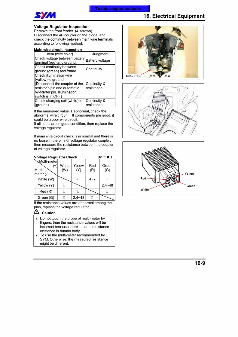
8/12/2019 SYM Mio50 Service Manual 000
http://slidepdf.com/reader/full/sym-mio50-service-manual-000 188/215
16. Electrical Equipment
16-9
Voltage Regulator InspectionRemove the front fender. (4 screws)Disconnect the 4P coupler on the diode, andcheck the continuity between main wire terminalsaccording to following method.
Main wire circuit inspectionItem (wire color) Judgment
Check voltage between batteryterminal (red) and ground.
Battery voltage
Check continuity betweenground (green) and frame.
Continuity
Check illumination wire(yellow) to ground.(Disconnect the coupler of theresistor’s pin and automaticby-starter pin. Illumination
switch is in OFF)
Continuity &resistance
Check charging coil (white) to(ground)
Continuity &resistance
If the measured value is abnormal, check theabnormal wire circuit. If components are good, itcould be a poor wire circuit.If all items are in good condition, then replace thevoltage regulator.
If main wire circuit check is in normal and there isno loose in the pins of voltage regulator coupler,then measure the resistance between the couplerof voltage regulator.
Voltage Regulator Check Unit: KΩ
Multi-meter (+)
Multi-meter (-)
White(W)
Yellow(Y)
Red(R)
Green(G)
White (W) ¡Û 4~7 ¡Û
Yellow (Y) ¡Û 2.4~48
Red (R) ¡Û ¡Û ¡Û
Green (G) ¡Û 2.4~48 ¡Û
If the resistance values are abnormal among thepins, replace the voltage regulator.
Caution
Do not touch the probe of multi-meter byfingers, then the resistance values will beincorrect because there is some resistanceexistence in human body.
To use the multi-meter recommended bySYM. Otherwise, the measured resistance
might be different.
Green
Red
White
Yellow
REG. REC.
To this chapter contents
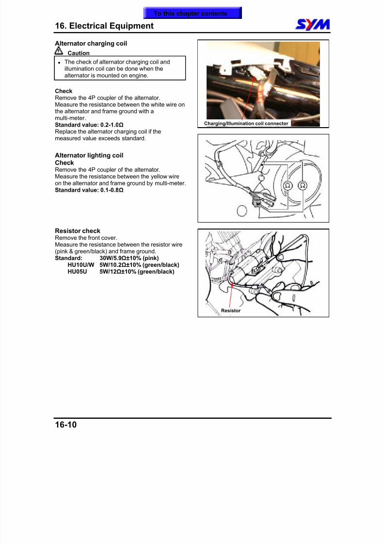
8/12/2019 SYM Mio50 Service Manual 000
http://slidepdf.com/reader/full/sym-mio50-service-manual-000 189/215
16. Electrical Equipment
16-10
Alternator charging coil
Caution
The check of alternator charging coil andillumination coil can be done when thealternator is mounted on engine.
CheckRemove the 4P coupler of the alternator.Measure the resistance between the white wire onthe alternator and frame ground with amulti-meter.Standard value: 0.2-1.0Ω Replace the alternator charging coil if themeasured value exceeds standard.
Alternator lighting coilCheckRemove the 4P coupler of the alternator.Measure the resistance between the yellow wireon the alternator and frame ground by multi-meter.Standard value: 0.1-0.8Ω
Resistor check
Remove the front cover.Measure the resistance between the resistor wire(pink & green/black) and frame ground.Standard: 30W/5.9Ω±10% (pink)
HU10U/W 5W/10.2Ω±10% (green/black)HU05U 5W/12Ω±10% (green/black)
Resistor
Charging/Illumination coil connector
To this chapter contents
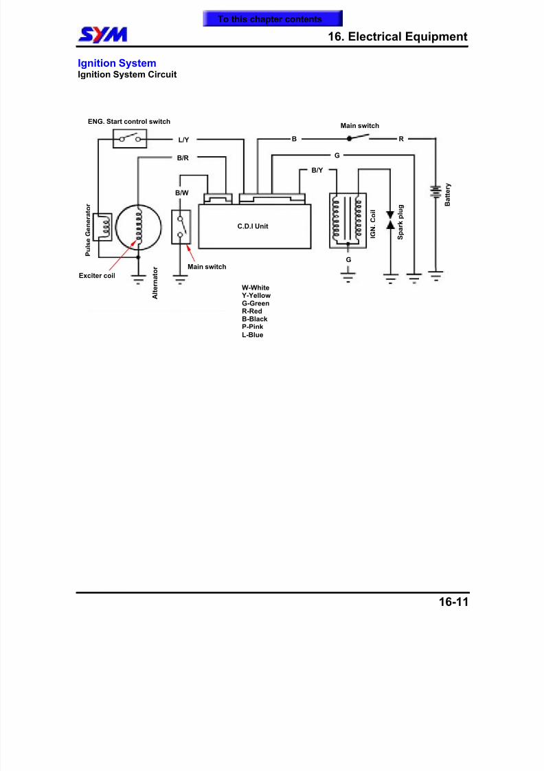
8/12/2019 SYM Mio50 Service Manual 000
http://slidepdf.com/reader/full/sym-mio50-service-manual-000 190/215
16. Electrical Equipment
16-11
Ignition SystemIgnition System Circuit
S p a r k
p l u g
I G N .
C o i l
C.D.I Unit
G
B/Y
GB/R
B/W
B R
B a t t e r y
Main switch
L/Y
ENG. Start control switch
W-White Y-YellowG-GreenR-RedB-BlackP-Pink
L-Blue
Main switch
Exciter coil
A l t e r n a t o r
P u l s e G e n e r a t o r
To this chapter contents
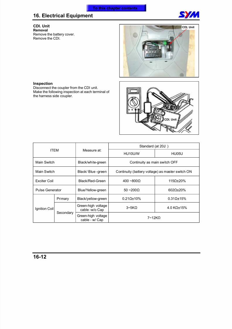
8/12/2019 SYM Mio50 Service Manual 000
http://slidepdf.com/reader/full/sym-mio50-service-manual-000 191/215
16. Electrical Equipment
16-12
CDI. UnitRemovalRemove the battery cover.Remove the CDI.
InspectionDisconnect the coupler from the CDI unit.Make the following inspection at each terminal of
the harness side coupler.
Standard (at 20¢J )ITEM Measure at:
HU10U/W HU05U
Main Switch Black/white-green Continuity as main switch OFF
Main Switch Black/ Blue -green Continuity (battery voltage) as master switch ON
Exciter Coil Black/Red-Green 400 ~800Ω 115Ω±20%
Pulse Generator Blue/Yellow-green 50 ~200Ω
602Ω
±20%
Primary Black/yellow-green 0.21Ω±10% 0.31Ω±15%
Green-high voltagecable -w/o Cap
3~5KΩ 4.0 KΩ±15%Ignition CoilSecondary
Green-high voltagecable - w/ Cap
7~12KΩ
CDI. Unit
CDI. Unit
To this chapter contents
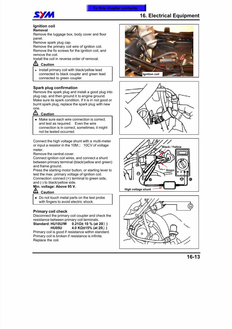
8/12/2019 SYM Mio50 Service Manual 000
http://slidepdf.com/reader/full/sym-mio50-service-manual-000 192/215
16. Electrical Equipment
16-13
Ignition coilRemovalRemove the luggage box, body cover and floorpanel.Remove spark plug cap.
Remove the primary coil wire of ignition coil.Remove the fix screws for the ignition coil, andremove the coil.Install the coil in reverse order of removal.
Caution
Install primary coil with black/yellow leadconnected to black coupler and green leadconnected to green coupler.
Spark plug confirmationRemove the spark plug and install a good plug into
plug cap, and then ground it to engine ground.Make sure its spark condition. If it is in not good orburnt spark plug, replace the spark plug with newone.
Caution Make sure each wire connection is correct,
and test as required. Even the wireconnection is in correct, sometimes; it mightnot be tested occurred.
Connect the high voltage shunt with a multi-meteror input a resistor in the 10M£[ 10CV of voltage
meter.Remove the central cover.Connect ignition coil wires, and connect a shuntbetween primary terminal (black/yellow and green)and frame ground.Press the starting motor button, or starting lever totest the max. primary voltage of ignition coil.Connection: connect (+) terminal to green side,and (-) to black/yellow side.Min. voltage: Above 95 V.
Caution Do not touch metal parts on the test probe
with fingers to avoid electric shock.
Primary coil checkDisconnect the primary coil coupler and check theresistance between primary coil terminals.Standard: HU10U/W 0.21Ω± 10 % (at 20¢ )
HU05U 4.0 KΩ±15% (at 20¢ )Primary coil is good if resistance within standard.Primary coil is broken if resistance is infinite.
Replace the coil.
High voltage shunt
Green
Ignition coil
Black / Yellow
To this chapter contents
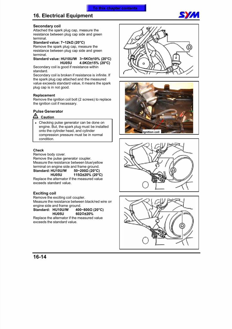
8/12/2019 SYM Mio50 Service Manual 000
http://slidepdf.com/reader/full/sym-mio50-service-manual-000 193/215
16. Electrical Equipment
16-14
Secondary coil Attached the spark plug cap, measure theresistance between plug cap side and greenterminal.Standard value: 7~12kΩ (20°C)
Remove the spark plug cap, measure theresistance between plug cap side and greenterminal.Standard value: HU10U/W 3~5KΩ±10% (20°C)
HU05U 4.0KΩ±15% (20°C)Secondary coil is good if resistance withinstandard.Secondary coil is broken if resistance is infinite. Ifthe spark plug cap attached and the measuredvalue exceeds standard value, it means the sparkplug cap is in not good.
ReplacementRemove the ignition coil bolt (2 screws) to replacethe ignition coil if necessary.
Pulse Generator
Caution
Checking pulse generator can be done onengine. But, the spark plug must be installedonto the cylinder head, and cylindercompression pressure must be in normalcondition.
CheckRemove body cover.Remove the pulse generator coupler.Measure the resistance between blue/yellowterminal on engine side and frame ground.Standard: HU10U/W 50~200Ω (20°C)
HU05U 115Ω±20% (20°C)Replace the alternator if the measured valueexceeds standard value.
Exciting coilRemove the exciting coil coupler.Measure the resistance between black/red wire onengine side and frame ground.Standard: HU10U/W 400~800Ω (20°C)
HU05U 602Ω±20%Replace the alternator if the measured valueexceeds the standard value.
Ignition coil
To this chapter contents
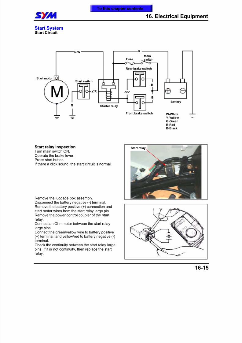
8/12/2019 SYM Mio50 Service Manual 000
http://slidepdf.com/reader/full/sym-mio50-service-manual-000 194/215
16. Electrical Equipment
16-15
Start SystemStart Circuit
Start relay inspectionTurn main switch ON.Operate the brake lever.Press start button.If there a click sound, the start circuit is normal.
Remove the luggage box assembly.Disconnect the battery negative (-) terminal.Remove the battery positive (+) connection andstart motor wires from the start relay large pin.Remove the power control coupler of the startrelay.Connect an Ohmmeter between the start relaylarge pins.Connect the green/yellow wire to battery positive(+) terminal, and yellow/red to battery negative (-)terminal.Check the continuity between the start relay large
pins. If it is not continuity, then replace the startrelay.
FuseMainswitch
Rear brake switch
Start switch
Starter relay
Start motor
R
Y/R G/Y
Battery
Front brake switch
G
B
B
Start relay
R/W
W-White Y-YellowG-GreenR-RedB-Black
To this chapter contents
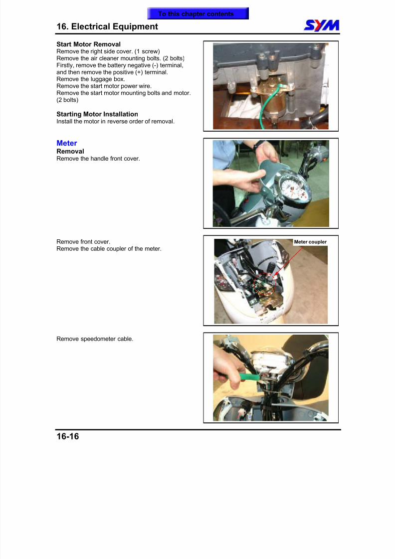
8/12/2019 SYM Mio50 Service Manual 000
http://slidepdf.com/reader/full/sym-mio50-service-manual-000 195/215
16. Electrical Equipment
16-16
Start Motor RemovalRemove the right side cover. (1 screw)Remove the air cleaner mounting bolts. (2 bolts)Firstly, remove the battery negative (-) terminal,and then remove the positive (+) terminal.
Remove the luggage box.Remove the start motor power wire.Remove the start motor mounting bolts and motor.(2 bolts)
Starting Motor InstallationInstall the motor in reverse order of removal.
MeterRemovalRemove the handle front cover.
Remove front cover.Remove the cable coupler of the meter.
Remove speedometer cable.
Meter coupler
To this chapter contents
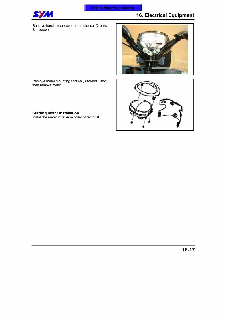
8/12/2019 SYM Mio50 Service Manual 000
http://slidepdf.com/reader/full/sym-mio50-service-manual-000 196/215
16. Electrical Equipment
16-17
Remove handle rear cover and meter set (2 bolts& 1 screw).
Remove meter mounting screws (3 screws), andthen remove meter.
Starting Motor InstallationInstall the meter in reverse order of removal.
To this chapter contents
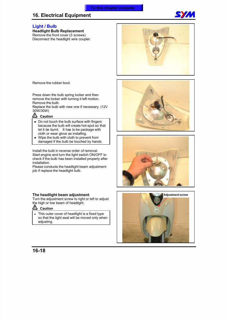
8/12/2019 SYM Mio50 Service Manual 000
http://slidepdf.com/reader/full/sym-mio50-service-manual-000 197/215
16. Electrical Equipment
16-18
Light / BulbHeadlight Bulb ReplacementRemove the front cover (3 screws)Disconnect the headlight wire coupler.
Remove the rubber boot.
Press down the bulb spring locker and thenremove the locker with turning it left motion.Remove the bulb.Replace the bulb with new one if necessary. (12V30W/30W)
Caution
Do not touch the bulb surface with fingersbecause the bulb will create hot-spot so thatlet it be burnt. It has to be package withcloth or wear glove as installing.
Wipe the bulb with cloth to prevent fromdamaged if the bulb be touched by hands.
Install the bulb in reverse order of removal.Start engine and turn the light switch ON/OFF tocheck if the bulb has been installed properly afterinstallation.Please conducts the headlight beam adjustment job if replace the headlight bulb.
The headlight beam adjustmentTurn the adjustment screw to right or left to adjustthe high or low beam of headlight.
Caution
This outer cover of headlight is a fixed typeso that the light seat will be moved only whenadjusting.
Adjustment screw
To this chapter contents
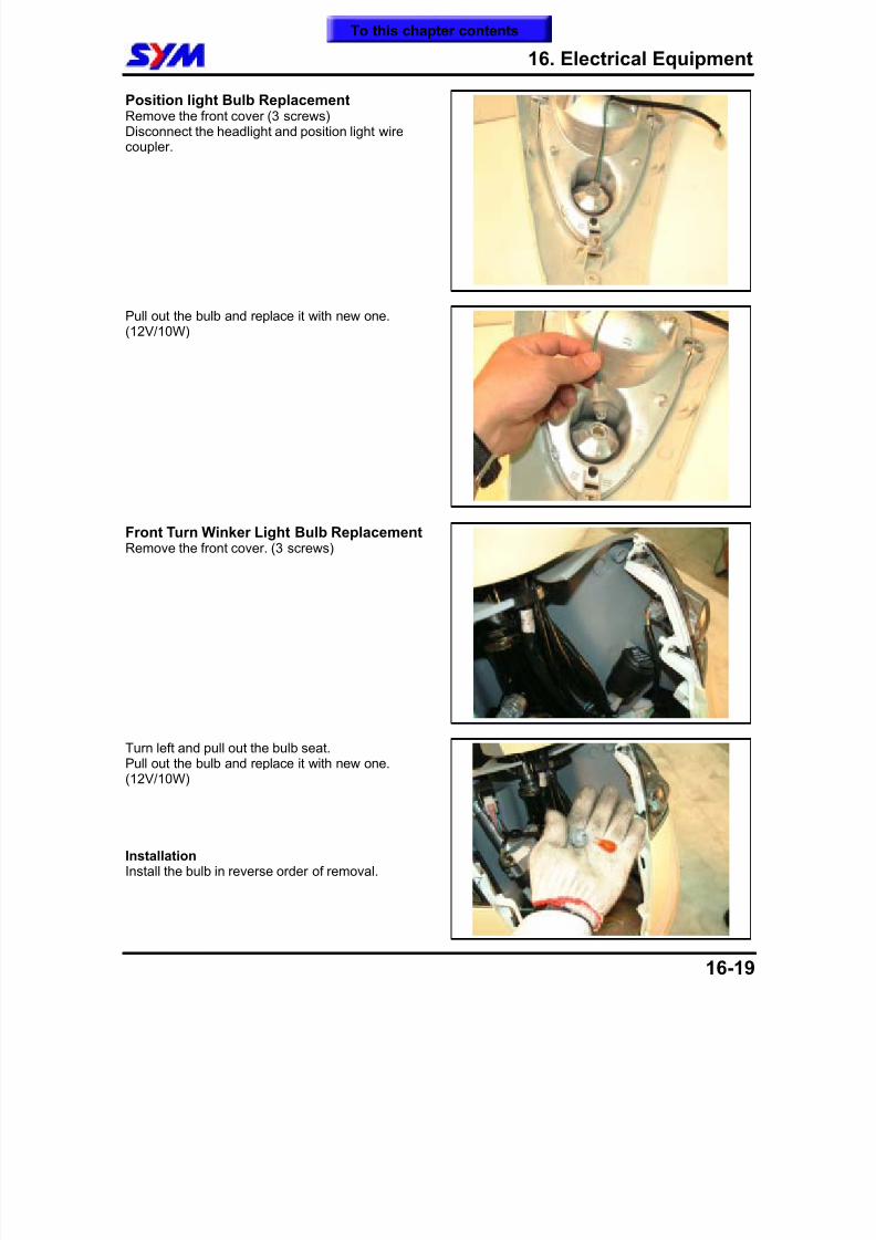
8/12/2019 SYM Mio50 Service Manual 000
http://slidepdf.com/reader/full/sym-mio50-service-manual-000 198/215
16. Electrical Equipment
16-19
Position light Bulb ReplacementRemove the front cover (3 screws)Disconnect the headlight and position light wirecoupler.
Pull out the bulb and replace it with new one.(12V/10W)
Front Turn Winker Light Bulb ReplacementRemove the front cover. (3 screws)
Turn left and pull out the bulb seat.Pull out the bulb and replace it with new one.(12V/10W)
InstallationInstall the bulb in reverse order of removal.
To this chapter contents
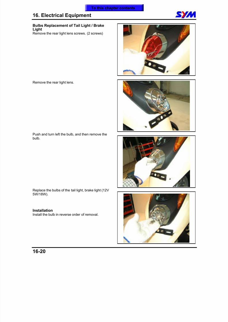
8/12/2019 SYM Mio50 Service Manual 000
http://slidepdf.com/reader/full/sym-mio50-service-manual-000 199/215
16. Electrical Equipment
16-20
Bulbs Replacement of Tail Light / BrakeLightRemove the rear light lens screws. (2 screws)
Remove the rear light lens.
Push and turn left the bulb, and then remove thebulb.
Replace the bulbs of the tail light, brake light (12V5W/18W).
InstallationInstall the bulb in reverse order of removal.
To this chapter contents
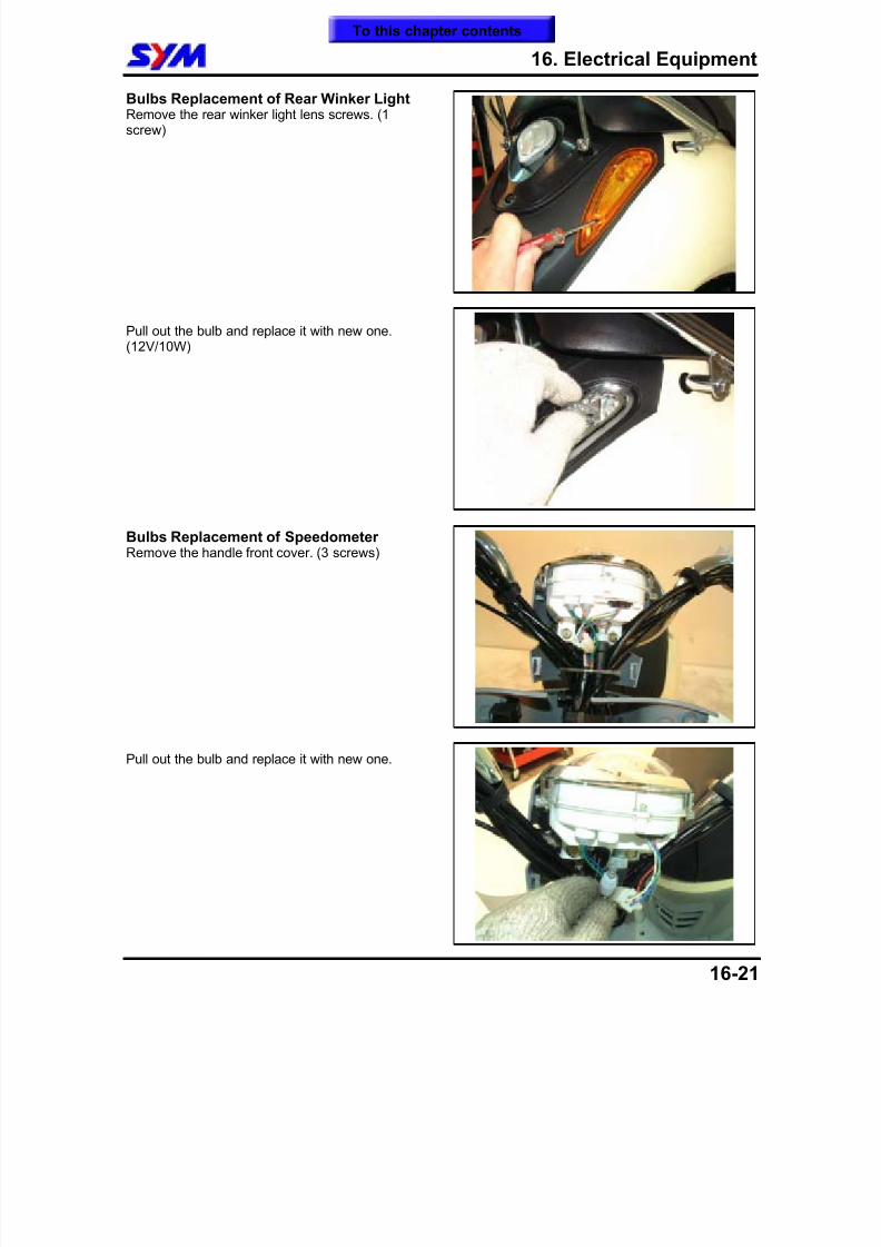
8/12/2019 SYM Mio50 Service Manual 000
http://slidepdf.com/reader/full/sym-mio50-service-manual-000 200/215
16. Electrical Equipment
16-21
Bulbs Replacement of Rear Winker LightRemove the rear winker light lens screws. (1screw)
Pull out the bulb and replace it with new one.(12V/10W)
Bulbs Replacement of SpeedometerRemove the handle front cover. (3 screws)
Pull out the bulb and replace it with new one.
To this chapter contents
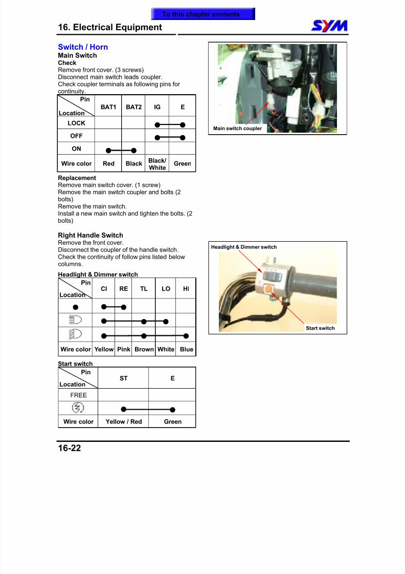
8/12/2019 SYM Mio50 Service Manual 000
http://slidepdf.com/reader/full/sym-mio50-service-manual-000 201/215
16. Electrical Equipment
16-22
Switch / HornMain Switch CheckRemove front cover. (3 screws)Disconnect main switch leads coupler.
Check coupler terminals as following pins forcontinuity.
Pin
Location BAT1 BAT2 IG E
LOCK OFF ON
Wire color Red BlackBlack/
WhiteGreen
ReplacementRemove main switch cover. (1 screw)Remove the main switch coupler and bolts (2bolts)Remove the main switch.Install a new main switch and tighten the bolts. (2bolts)
Right Handle SwitchRemove the front cover.
Disconnect the coupler of the handle switch.Check the continuity of follow pins listed belowcolumns.
Headlight & Dimmer switch
Pin
Location CI RE TL LO HI
Wire color Yellow Pink Brown White Blue
Start switch
Pin
Location ST E
FREE
Wire color Yellow / Red Green
Main switch coupler
Start switch
Headlight & Dimmer switch
To this chapter contents
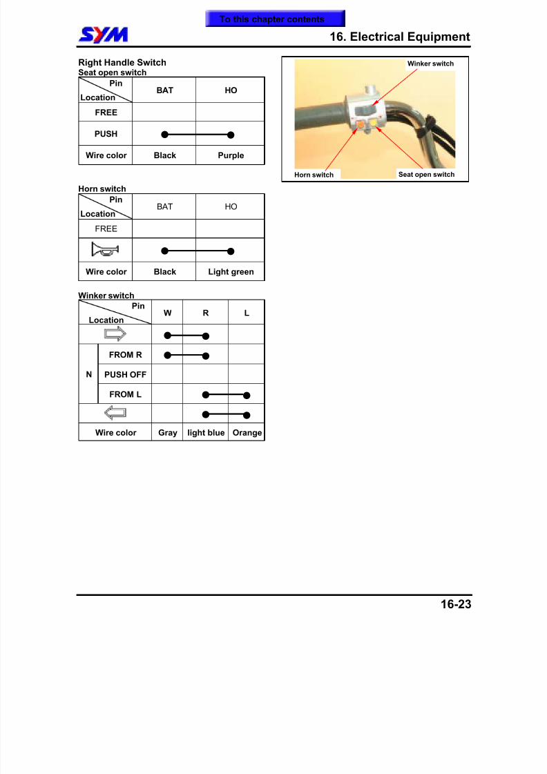
8/12/2019 SYM Mio50 Service Manual 000
http://slidepdf.com/reader/full/sym-mio50-service-manual-000 202/215
16. Electrical Equipment
16-23
Right Handle SwitchSeat open switch
Pin
Location BAT HO
FREE
PUSH Wire color Black Purple
Horn switch
Pin
Location BAT HO
FREE
Wire color Black Light green
Winker switch
Pin
Location W R L
FROM R
PUSH OFFN
FROM L
Wire color Gray light blue Orange
Winker switch
Seat open switchHorn switch
To this chapter contents
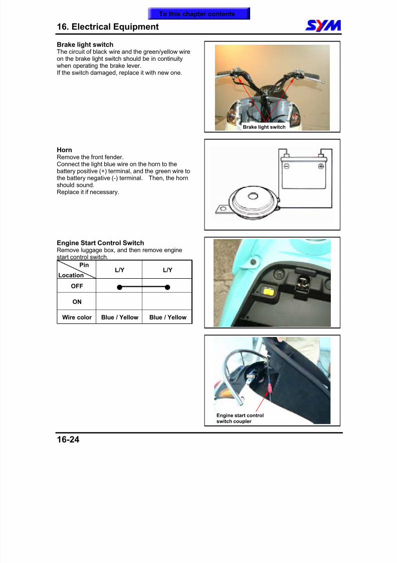
8/12/2019 SYM Mio50 Service Manual 000
http://slidepdf.com/reader/full/sym-mio50-service-manual-000 203/215
16. Electrical Equipment
16-24
Brake light switchThe circuit of black wire and the green/yellow wireon the brake light switch should be in continuitywhen operating the brake lever.If the switch damaged, replace it with new one.
HornRemove the front fender.
Connect the light blue wire on the horn to thebattery positive (+) terminal, and the green wire tothe battery negative (-) terminal. Then, the hornshould sound.Replace it if necessary.
Engine Start Control SwitchRemove luggage box, and then remove enginestart control switch.
Pin
Location L/Y L/Y
OFF
ON
Wire color Blue / Yellow Blue / Yellow
Engine start controlswitch coupler
Brake light switch
To this chapter contents
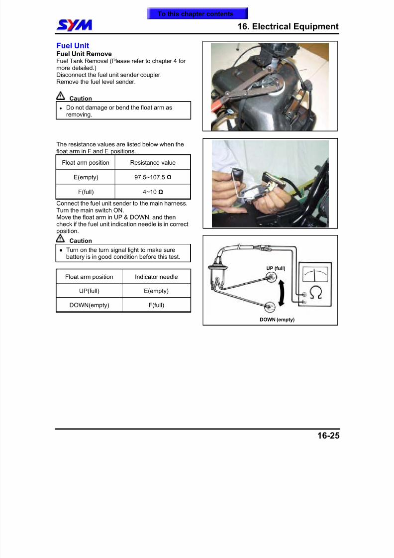
8/12/2019 SYM Mio50 Service Manual 000
http://slidepdf.com/reader/full/sym-mio50-service-manual-000 204/215
8/12/2019 SYM Mio50 Service Manual 000
http://slidepdf.com/reader/full/sym-mio50-service-manual-000 205/215
16. Electrical Equipment
16-26
Note:
To this chapter contents
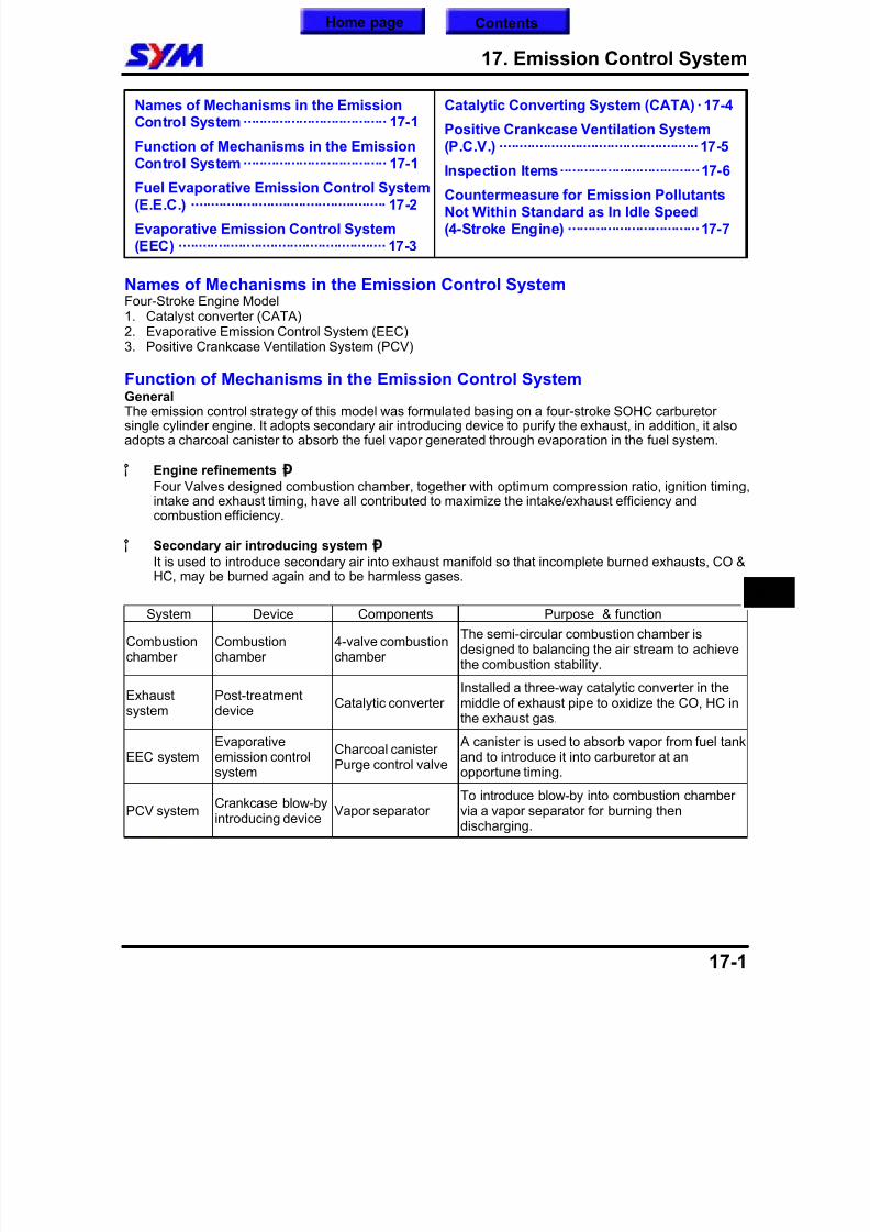
8/12/2019 SYM Mio50 Service Manual 000
http://slidepdf.com/reader/full/sym-mio50-service-manual-000 206/215
17. Emission Control System
17-1
Names of Mechanisms in the EmissionControl System···································· 17-1
Function of Mechanisms in the EmissionControl System···································· 17-1
Fuel Evaporative Emission Control System (E.E.C.) ················································· 17-2
Evaporative Emission Control System(EEC) ···················································· 17-3
Catalytic Converting System (CATA) ·17-4
Positive Crankcase Ventilation System(P.C.V.) ··················································17-5
Inspection Items···································17-6
Countermeasure for Emission PollutantsNot Within Standard as In Idle Speed(4-Stroke Engine) ·································17-7
Names of Mechanisms in the Emission Control SystemFour-Stroke Engine Model1. Catalyst converter (CATA)2. Evaporative Emission Control System (EEC)3. Positive Crankcase Ventilation System (PCV)
Function of Mechanisms in the Emission Control SystemGeneralThe emission control strategy of this model was formulated basing on a four-stroke SOHC carburetorsingle cylinder engine. It adopts secondary air introducing device to purify the exhaust, in addition, it alsoadopts a charcoal canister to absorb the fuel vapor generated through evaporation in the fuel system.
¡°
Engine refinements ¡Ð
Four Valves designed combustion chamber, together with optimum compression ratio, ignition timing,intake and exhaust timing, have all contributed to maximize the intake/exhaust efficiency andcombustion efficiency.
¡°
Secondary air introducing system¡Ð
It is used to introduce secondary air into exhaust manifold so that incomplete burned exhausts, CO &HC, may be burned again and to be harmless gases.
System Device Components Purpose & function
Combustionchamber
Combustionchamber
4-valve combustionchamber
The semi-circular combustion chamber isdesigned to balancing the air stream to achievethe combustion stability.
Exhaust
system
Post-treatment
device
Catalytic converterInstalled a three-way catalytic converter in themiddle of exhaust pipe to oxidize the CO, HC in
the exhaust gas.
EEC systemEvaporativeemission controlsystem
Charcoal canisterPurge control valve
A canister is used to absorb vapor from fuel tankand to introduce it into carburetor at anopportune timing.
PCV systemCrankcase blow-byintroducing device
Vapor separatorTo introduce blow-by into combustion chambervia a vapor separator for burning thendischarging.
17
Home page Contents
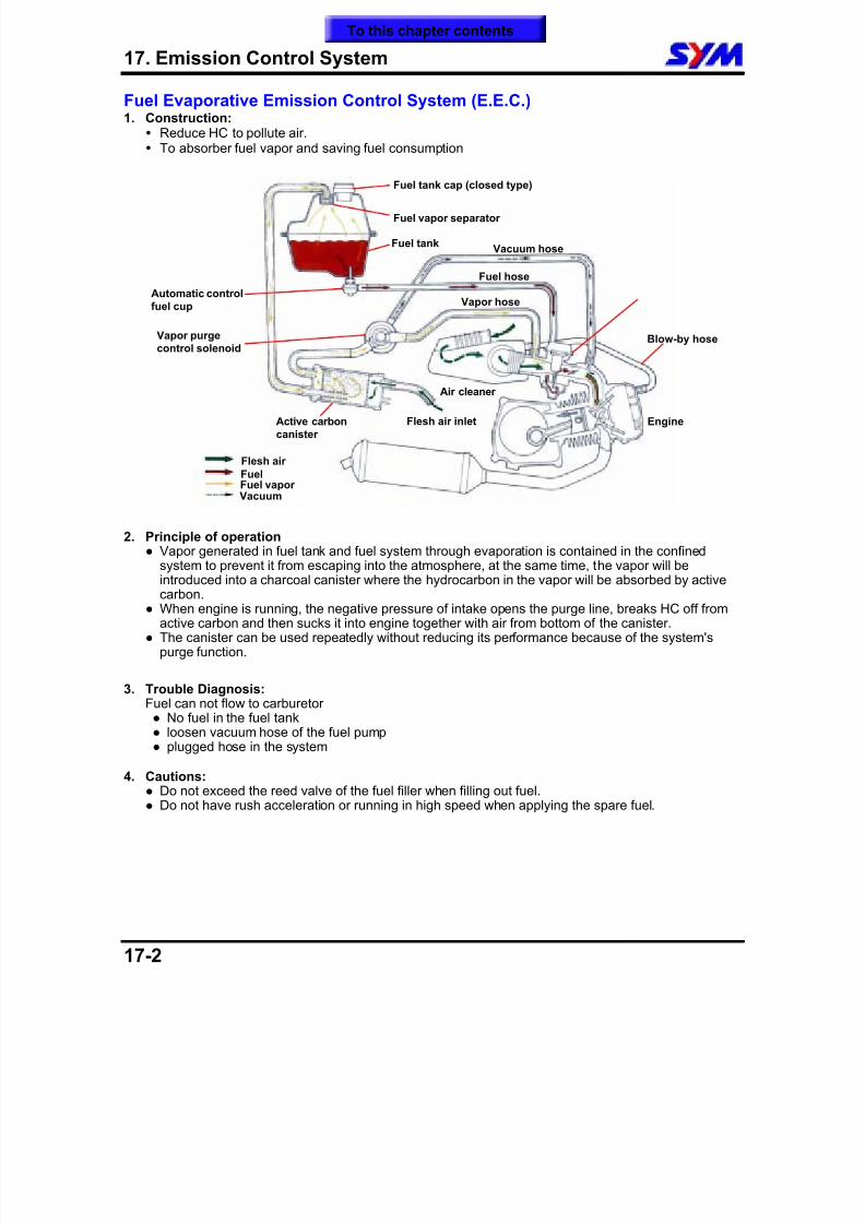
8/12/2019 SYM Mio50 Service Manual 000
http://slidepdf.com/reader/full/sym-mio50-service-manual-000 207/215
17. Emission Control System
17-2
Fuel Evaporative Emission Control System (E.E.C.)1. Construction:
Reduce HC to pollute air. To absorber fuel vapor and saving fuel consumption
2. Principle of operation Vapor generated in fuel tank and fuel system through evaporation is contained in the confined
system to prevent it from escaping into the atmosphere, at the same time, the vapor will beintroduced into a charcoal canister where the hydrocarbon in the vapor will be absorbed by activecarbon.
When engine is running, the negative pressure of intake opens the purge line, breaks HC off fromactive carbon and then sucks it into engine together with air from bottom of the canister.
The canister can be used repeatedly without reducing its performance because of the system'spurge function.
3. Trouble Diagnosis:Fuel can not flow to carburetor No fuel in the fuel tank loosen vacuum hose of the fuel pump plugged hose in the system
4. Cautions: Do not exceed the reed valve of the fuel filler when filling out fuel. Do not have rush acceleration or running in high speed when applying the spare fuel.
Automatic controlfuel cup
Active carboncanister
Vacuum hose
Flesh air inlet
Blow-by hose
Flesh air FuelFuel vapor Vacuum
Engine
Fuel vapor separator
Fuel tank cap (closed type)
Fuel tank
Fuel hose
Vapor hose
Vapor purgecontrol solenoid
Air cleaner
To this chapter contents
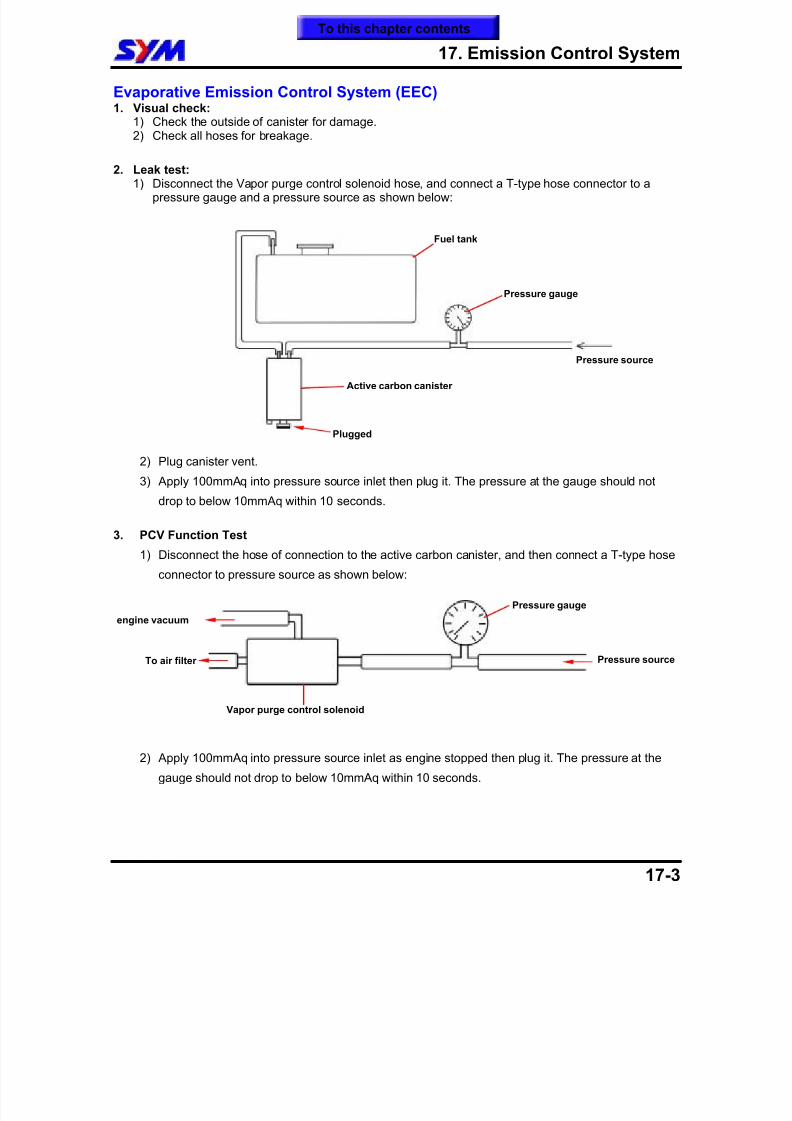
8/12/2019 SYM Mio50 Service Manual 000
http://slidepdf.com/reader/full/sym-mio50-service-manual-000 208/215
17. Emission Control System
17-3
Evaporative Emission Control System (EEC)1. Visual check:
1) Check the outside of canister for damage.2) Check all hoses for breakage.
2. Leak test:1) Disconnect the Vapor purge control solenoid hose, and connect a T-type hose connector to a
pressure gauge and a pressure source as shown below:
2) Plug canister vent.
3) Apply 100mmAq into pressure source inlet then plug it. The pressure at the gauge should not
drop to below 10mmAq within 10 seconds.
3. PCV Function Test
1) Disconnect the hose of connection to the active carbon canister, and then connect a T-type hose
connector to pressure source as shown below:
2) Apply 100mmAq into pressure source inlet as engine stopped then plug it. The pressure at the
gauge should not drop to below 10mmAq within 10 seconds.
Pressure source
Pressure gauge
Fuel tank
Active carbon canister
Plugged
To air filter
engine vacuum
Vapor purge control solenoid
Pressure gauge
Pressure source
To this chapter contents
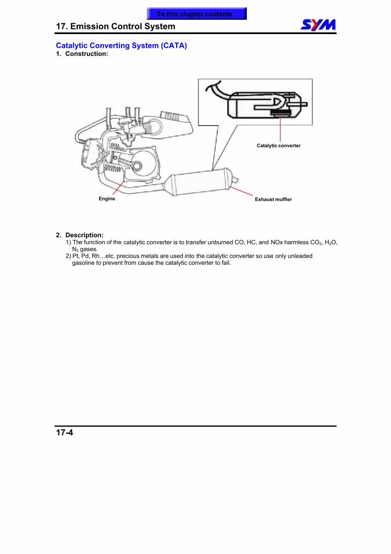
8/12/2019 SYM Mio50 Service Manual 000
http://slidepdf.com/reader/full/sym-mio50-service-manual-000 209/215
17. Emission Control System
17-4
Catalytic Converting System (CATA)1. Construction:
2. Description:
1) The function of the catalytic converter is to transfer unburned CO, HC, and NOx harmless CO2, H2O,N2 gases.
2) Pt, Pd, Rh…etc. precious metals are used into the catalytic converter so use only unleadedgasoline to prevent from cause the catalytic converter to fail.
Engine Exhaust muffler
Catalytic converter
To this chapter contents
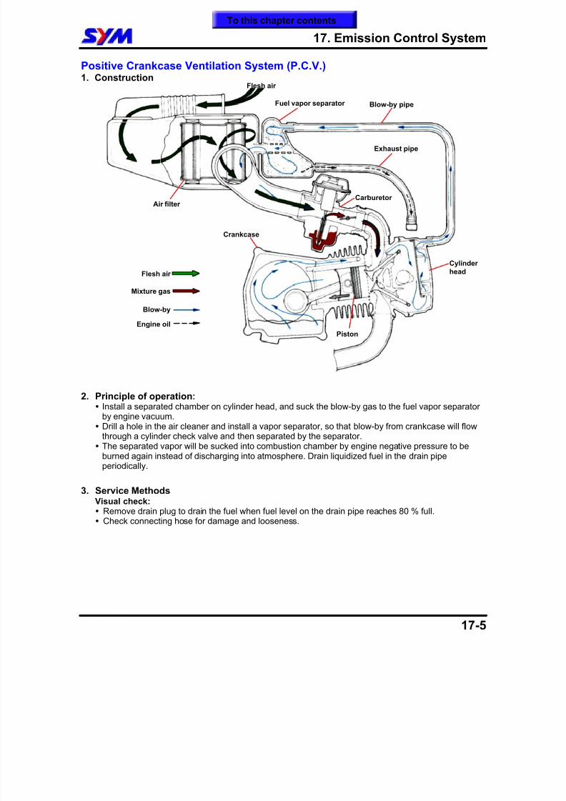
8/12/2019 SYM Mio50 Service Manual 000
http://slidepdf.com/reader/full/sym-mio50-service-manual-000 210/215
17. Emission Control System
17-5
Positive Crankcase Ventilation System (P.C.V.)1. Construction
2. Principle of operation: Install a separated chamber on cylinder head, and suck the blow-by gas to the fuel vapor separator
by engine vacuum. Drill a hole in the air cleaner and install a vapor separator, so that blow-by from crankcase will flow
through a cylinder check valve and then separated by the separator. The separated vapor will be sucked into combustion chamber by engine negative pressure to be
burned again instead of discharging into atmosphere. Drain liquidized fuel in the drain pipe
periodically.
3. Service Methods Visual check: Remove drain plug to drain the fuel when fuel level on the drain pipe reaches 80 % full. Check connecting hose for damage and looseness.
Cylinderhead
Carburetor
Flesh air
Exhaust pipe
Air filter
Fuel vapor separator
Crankcase
Blow-by pipe
Piston
Flesh air
Mixture gas
Blow-by
Engine oil
To this chapter contents
8/12/2019 SYM Mio50 Service Manual 000
http://slidepdf.com/reader/full/sym-mio50-service-manual-000 211/215
17. Emission Control System
17-6
Inspection ItemsSecondary air injection system1. Visual inspect the reed valve, air injection cut valve, and secondary air filter as well as hoses for
damage.2. Leaking check.
3. Warm-up running check.
Fuel Evaporation Control System1. Visual inspect the carbon canister and hoses for damage.2. Leaking check.3. Function test of the purge control solenoid.
Catalytic converter1. Check if exhaust gas content is within standard.2. Remove the exhaust pipe and shake it gently for noise.
Fuel Supply System1. Clean the air filter.2. Check the air filter.3. Clean the carburetor fuel jet, air jet and all circuit with air gun or specified solvent.4. Check the float level of carburetor.5. Adjust CO/HC values at idling. (engine rpm must be within specification)
Ignition system1. Spark plug check and replacement.2. Ignition coil check and replacement.
To this chapter contents
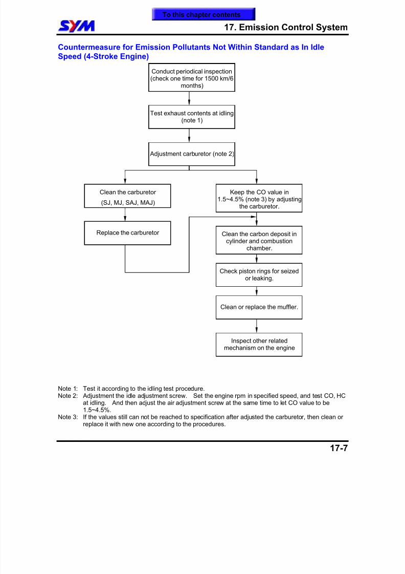
8/12/2019 SYM Mio50 Service Manual 000
http://slidepdf.com/reader/full/sym-mio50-service-manual-000 212/215
17. Emission Control System
17-7
Countermeasure for Emission Pollutants Not Within Standard as In IdleSpeed (4-Stroke Engine)
Note 1: Test it according to the idling test procedure.Note 2: Adjustment the idle adjustment screw. Set the engine rpm in specified speed, and test CO, HC
at idling. And then adjust the air adjustment screw at the same time to let CO value to be1.5~4.5%.
Note 3: If the values still can not be reached to specification after adjusted the carburetor, then clean orreplace it with new one according to the procedures.
Conduct periodical inspection(check one time for 1500 km/6
months)
Test exhaust contents at idling(note 1)
Adjustment carburetor (note 2)
Clean the carburetor
(SJ, MJ, SAJ, MAJ)
Replace the carburetor
Keep the CO value in1.5~4.5% (note 3) by adjusting
the carburetor.
Clean the carbon deposit incylinder and combustion
chamber.
Check piston rings for seizedor leaking.
Clean or replace the muffler.
Inspect other relatedmechanism on the engine
To this chapter contents
8/12/2019 SYM Mio50 Service Manual 000
http://slidepdf.com/reader/full/sym-mio50-service-manual-000 213/215
17. Emission Control System
17-8
Note:
To this chapter contents
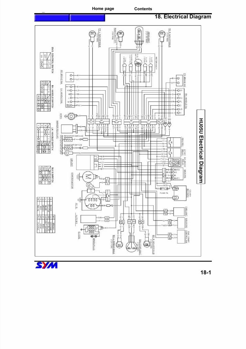
8/12/2019 SYM Mio50 Service Manual 000
http://slidepdf.com/reader/full/sym-mio50-service-manual-000 214/215
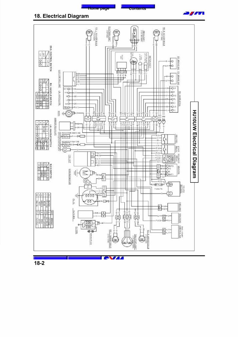
8/12/2019 SYM Mio50 Service Manual 000
http://slidepdf.com/reader/full/sym-mio50-service-manual-000 215/215