Embed Size (px)
Citation preview
Syllacon NOTES
SINGAPORE-CAMBRIDGE GCE O-LEVEL
PHYSICS OUTLINE
SYLLABUS 5059
UPDATED 20 JAN 2014
syllacon.weebly.com
2 ‘Consylladated’ by Lim Ting Jie
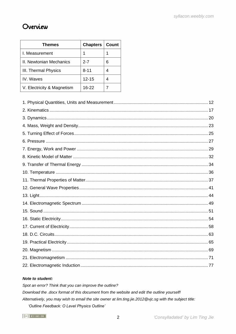
Overview
Themes Chapters Count
I. Measurement 1 1
II. Newtonian Mechanics 2-7 6
III. Thermal Physics 8-11 4
IV. Waves 12-15 4
V. Electricity & Magnetism 16-22 7
1. Physical Quantities, Units and Measurement ............................................................................ 12
2. Kinematics ................................................................................................................................ 17
3. Dynamics .................................................................................................................................. 20
4. Mass, Weight and Density......................................................................................................... 23
5. Turning Effect of Forces ............................................................................................................ 25
6. Pressure ................................................................................................................................... 27
7. Energy, Work and Power .......................................................................................................... 29
8. Kinetic Model of Matter ............................................................................................................. 32
9. Transfer of Thermal Energy ...................................................................................................... 34
10. Temperature ........................................................................................................................... 36
11. Thermal Properties of Matter ................................................................................................... 37
12. General Wave Properties ........................................................................................................ 41
13. Light ........................................................................................................................................ 44
14. Electromagnetic Spectrum ...................................................................................................... 49
15. Sound ..................................................................................................................................... 51
16. Static Electricity ....................................................................................................................... 54
17. Current of Electricity ................................................................................................................ 58
18. D.C. Circuits ............................................................................................................................ 63
19. Practical Electricity .................................................................................................................. 65
20. Magnetism .............................................................................................................................. 69
21. Electromagnetism ................................................................................................................... 71
22. Electromagnetic Induction ....................................................................................................... 77
Note to student:
Spot an error? Think that you can improve the outline?
Download the .docx format of this document from the website and edit the outline yourself!
Alternatively, you may wish to email the site owner at [email protected] with the subject title:
‘Outline Feedback: O Level Physics Outline’
syllacon.weebly.com
3 ‘Consylladated’ by Lim Ting Jie
Contents
1. Physical Quantities, Units and Measurement ....................................................................... 12
(a) show understanding that all physical quantities consist of a numerical magnitude and a unit12
(b) recall the following base quantities and their units: mass (kg), length (m), time (s), current (A),
temperature (K), amount of substance (mol) ............................................................................. 12
(c) use the following prefixes and their symbols to indicate decimal sub-multiples and multiples of
the SI units: nano (n), micro (μ), milli (m), centi (c), deci (d), kilo (k), mega (M), giga (G) ........... 12
(d) show an understanding of the orders of magnitude of the sizes of common objects ranging
from a typical atom to the Earth ................................................................................................. 12
(e) state what is meant by scalar and vector quantities and give common examples of each .... 13
(f) add two vectors to determine a resultant by a graphical method ........................................... 13
(g) describe how to measure a variety of lengths with appropriate accuracy by means of tapes,
rules, micrometers and calipers, using a vernier scale as necessary ......................................... 14
(h) describe how to measure a short interval of time including the period of a simple pendulum
with appropriate accuracy using stopwatches or appropriate instruments.................................. 15
2. Kinematics ............................................................................................................................... 17
(a) state what is meant by speed and velocity ........................................................................... 17
(b) calculate average speed using distance travelled / time taken ............................................. 17
(c) state what is meant by uniform acceleration and calculate the value of an acceleration using
change in velocity / time taken ................................................................................................... 17
(d) interpret given examples of non-uniform acceleration .......................................................... 18
(e) plot and interpret a displacement-time graph and a velocity-time graph ............................... 18
(f) deduce from the shape of a displacement-time graph when a body is: (i) at rest (ii) moving
with uniform velocity (iii) moving with non-uniform velocity ........................................................ 18
(g) deduce from the shape of a velocity-time graph when a body is: (i) at rest (ii) moving with
uniform velocity (iii) moving with uniform acceleration (iv) moving with non-uniform acceleration
.................................................................................................................................................. 18
(h) calculate the area under a velocity-time graph to determine the displacement travelled for
motion with uniform velocity or uniform acceleration .................................................................. 19
(i) state that the acceleration of free fall for a body near to the Earth is constant and is
approximately 10 m/s2 ............................................................................................................... 19
(j) describe the motion of bodies with constant weight falling with or without air resistance,
including reference to terminal velocity ...................................................................................... 19
3. Dynamics ................................................................................................................................. 20
(a) apply Newton's Laws to: (i) describe the effect of balanced and unbalanced forces on a body
(ii) describe the ways in which a force may change the motion of a body (iii) identify action-
reaction pairs acting on two interacting bodies (stating of Newton's Laws is not required) ......... 20
(b) identify forces acting on an object and draw free body diagram(s) representing the forces
acting on the object (for cases involving forces acting in at most 2 dimensions) ........................ 21
syllacon.weebly.com
4 ‘Consylladated’ by Lim Ting Jie
(c) solve problems for a static point mass under the action of 3 forces for 2-dimensional cases (a
graphical method would suffice) ................................................................................................ 21
(d) recall and apply the relationship resultant force = mass × acceleration to new situations or to
solve related problems .............................................................................................................. 22
(e) explain the effects of friction on the motion of a body ........................................................... 22
4. Mass, Weight and Density ...................................................................................................... 23
(a) state that mass is a measure of the amount of substance in a body (b) state that mass of a
body resists a change in the state of rest or motion of the body (inertia).................................... 23
(c) state that a gravitational field is a region in which a mass experiences a force due to
gravitational attraction ............................................................................................................... 23
(d) define gravitational field strength, g, as gravitational force per unit mass ............................. 23
(e) recall and apply the relationship weight = mass × gravitational field strength to new situations
or to solve related problems ...................................................................................................... 23
(f) distinguish between mass and weight ................................................................................... 24
(g) recall and apply the relationship density = mass / volume to new situations or to solve related
problems ................................................................................................................................... 24
5. Turning Effect of Forces ......................................................................................................... 25
(a) describe the moment of a force in terms of its turning effect and relate this to everyday
examples (b) recall and apply the relationship moment of a force (or torque) = force ×
perpendicular distance from the pivot to new situations or to solve related problems ................ 25
(c) state the principle of moments for a body in equilibrium (d) apply the principle of moments to
new situations or to solve related problems ............................................................................... 25
(e) show understanding that the weight of a body may be taken as acting at a single point known
as its centre of gravity................................................................................................................ 25
(f) describe qualitatively the effect of the position of the centre of gravity on the stability of objects
.................................................................................................................................................. 26
6. Pressure .................................................................................................................................. 27
(a) define the term pressure in terms of force and area (b) recall and apply the relationship
pressure = force / area to new situations or to solve related problems....................................... 27
(c) describe and explain the transmission of pressure in hydraulic systems with particular
reference to the hydraulic press ................................................................................................ 27
(d) recall and apply the relationship pressure due to a liquid column = height of column × density
of the liquid × gravitational field strength to new situations or to solve related problems ............ 28
(e) describe how the height of a liquid column may be used to measure the atmospheric
pressure .................................................................................................................................... 28
(f) describe the use of a manometer in the measurement of pressure difference ....................... 28
7. Energy, Work and Power ........................................................................................................ 29
(a) show understanding that kinetic energy, potential energy (chemical, gravitational, elastic),
light energy, thermal energy, electrical energy and nuclear energy are examples of different
forms of energy ......................................................................................................................... 29
(b) state the principle of the conservation of energy and apply the principle to new situations or to
solve related problems .............................................................................................................. 29
syllacon.weebly.com
5 ‘Consylladated’ by Lim Ting Jie
(c) calculate the efficiency of an energy conversion using the formula efficiency = energy
converted to useful output / total energy input ........................................................................... 29
(d) state that kinetic energy Ek = ½ mv2 and gravitational potential energy Ep = mgh (for potential
energy changes near the Earth’s surface) (e) apply the relationships for kinetic energy and
potential energy to new situations or to solve related problems ................................................. 30
(f) recall and apply the relationship work done = force × distance moved in the direction of the
force to new situations or to solve related problems .................................................................. 30
(g) recall and apply the relationship power = work done / time taken to new situations or to solve
related problems ........................................................................................................................ 30
8. Kinetic Model of Matter ........................................................................................................... 32
(a) compare the properties of solids, liquids and gases ............................................................. 32
(b) describe qualitatively the molecular structure of solids, liquids and gases, relating their
properties to the forces and distances between molecules and to the motion of the molecules . 32
(c) infer from Brownian motion experiment the evidence for the movement of molecules .......... 32
(d) describe the relationship between the motion of molecules and temperature ....................... 33
(e) explain the pressure of a gas in terms of the motion of its molecules ................................... 33
(f) recall and explain the following relationships using the kinetic model (stating of the
corresponding gas laws is not required): (i) a change in pressure of a fixed mass of gas at
constant volume is caused by a change in temperature of the gas (ii) a change in volume
occupied by a fixed mass of gas at constant pressure is caused by a change in temperature of
the gas (iii) a change in pressure of a fixed mass of gas at constant temperature is caused by a
change in volume of the gas ...................................................................................................... 33
(g) use the relationships in (f) in related situations and to solve problems (a qualitative treatment
would suffice) ............................................................................................................................ 33
9. Transfer of Thermal Energy ................................................................................................... 34
(a) show understanding that thermal energy is transferred from a region of higher temperature to
a region of lower temperature .................................................................................................... 34
(b) describe, in molecular terms, how energy transfer occurs in solids ...................................... 34
(c) describe, in terms of density changes, convection in fluids ................................................... 34
(d) explain that energy transfer of a body by radiation does not require a material medium and
the rate of energy transfer is affected by: (i) colour and texture of the surface (ii) surface
temperature (iii) surface area ..................................................................................................... 34
(e) apply the concept of thermal energy transfer to everyday applications ................................. 35
10. Temperature .......................................................................................................................... 36
(a) explain how a physical property which varies with temperature, such as volume of liquid
column, resistance of metal wire and electromotive force (e.m.f.) produced by junctions formed
with wires of two different metals, may be used to define temperature scales ........................... 36
(b) describe the process of calibration of a liquid-in-glass thermometer, including the need for
fixed points such as the ice point and steam point ..................................................................... 36
11. Thermal Properties of Matter ............................................................................................... 37
(a) describe a rise in temperature of a body in terms of an increase in its internal energy (random
thermal energy) ......................................................................................................................... 37
syllacon.weebly.com
6 ‘Consylladated’ by Lim Ting Jie
(b) define the terms heat capacity and specific heat capacity .................................................... 37
(c) recall and apply the relationship thermal energy = mass × specific heat capacity × change in
temperature to new situations or to solve related problems ....................................................... 37
(d) describe melting/solidification and boiling/condensation as processes of energy transfer
without a change in temperature ............................................................................................... 38
(e) explain the difference between boiling and evaporation ....................................................... 38
(f) define the terms latent heat and specific latent heat .............................................................. 38
(g) recall and apply the relationship thermal energy = mass × specific latent heat to new
situations or to solve related problems ...................................................................................... 38
(h) explain latent heat in terms of molecular behaviour .............................................................. 39
(i) sketch and interpret a cooling curve ...................................................................................... 39
12. General Wave Properties ...................................................................................................... 41
(a) describe what is meant by wave motion as illustrated by vibrations in ropes and springs and
by waves in a ripple tank ........................................................................................................... 41
(b) show understanding that waves transfer energy without transferring matter......................... 42
(c) define speed, frequency, wavelength, period and amplitude ................................................ 42
(d) state what is meant by the term wavefront ........................................................................... 43
(e) recall and apply the relationship velocity = frequency × wavelength to new situations or to
solve related problems .............................................................................................................. 43
(f) compare transverse and longitudinal waves and give suitable examples of each .................. 43
13. Light ....................................................................................................................................... 44
(a) recall and use the terms for reflection, including normal, angle of incidence and angle of
reflection.................................................................................................................................... 44
(b) state that, for reflection, the angle of incidence is equal to the angle of reflection and use this
principle in constructions, measurements and calculations ........................................................ 44
(c) recall and use the terms for refraction, including normal, angle of incidence and angle of
refraction ................................................................................................................................... 45
(d) recall and apply the relationship sin i / sin r = constant to new situations or to solve related
problems (e) define refractive index of a medium in terms of the ratio of speed of light in vacuum
and in the medium ..................................................................................................................... 45
(f) explain the terms critical angle and total internal reflection .................................................... 46
(g) identify the main ideas in total internal reflection and apply them to the use of optical fibres in
telecommunication and state the advantages of their use ......................................................... 46
(h) describe the action of a thin lens (both converging and diverging) on a beam of light .......... 47
(i) define the term focal length for a converging lens ................................................................. 47
(j) draw ray diagrams to illustrate the formation of real and virtual images of an object by a thin
converging lens ......................................................................................................................... 48
14. Electromagnetic Spectrum ................................................................................................... 49
(a) state that all electromagnetic waves are transverse waves that travel with the same speed in
vacuum and state the magnitude of this speed .......................................................................... 49
syllacon.weebly.com
7 ‘Consylladated’ by Lim Ting Jie
(b) describe the main components of the electromagnetic spectrum (c) state examples of the use
of the following components: (i) radiowaves (e.g. radio and television communication) (ii)
microwaves (e.g. microwave oven and satellite television) (iii) infra-red (e.g. infra-red remote
controllers and intruder alarms) (iv) light (e.g. optical fibres for medical uses and
telecommunications) (v) ultra-violet (e.g. sunbeds and sterilisation) (vi) X-rays (e.g. radiological
and engineering applications) (vii) gamma rays (e.g. medical treatment)................................... 50
(d) describe the effects of absorbing electromagnetic waves, e.g. heating, ionisation and damage
to living cells and tissue ............................................................................................................. 50
15. Sound..................................................................................................................................... 51
(a) describe the production of sound by vibrating sources (b) describe the longitudinal nature of
sound waves in terms of the processes of compression and rarefaction ................................... 51
(c) explain that a medium is required in order to transmit sound waves and the speed of sound
differs in air, liquids and solids ................................................................................................... 51
(d) describe a direct method for the determination of the speed of sound in air and make the
necessary calculation ................................................................................................................ 51
(e) relate loudness of a sound wave to its amplitude and pitch to its frequency ......................... 52
(f) describe how the reflection of sound may produce an echo, and how this may be used for
measuring distances ................................................................................................................. 52
(g) define ultrasound and describe one use of ultrasound, e.g. quality control and pre-natal
scanning .................................................................................................................................... 52
16. Static Electricity .................................................................................................................... 54
(a) state that there are positive and negative charges and that charge is measured in coulombs
.................................................................................................................................................. 54
(b) state that unlike charges attract and like charges repel ........................................................ 54
(c) describe an electric field as a region in which an electric charge experiences a force (d) draw
the electric field of an isolated point charge and recall that the direction of the field lines gives the
direction of the force acting on a positive test charge ................................................................ 54
(e) draw the electric field pattern between two isolated point charges ....................................... 55
(f) show understanding that electrostatic charging by rubbing involves a transfer of electrons ... 55
(g) describe experiments to show electrostatic charging by induction ........................................ 56
(h) describe examples where electrostatic charging may be a potential hazard ......................... 56
(i) describe the use of electrostatic charging in a photocopier, and apply the use of electrostatic
charging to new situations ......................................................................................................... 57
17. Current of Electricity ............................................................................................................. 58
(a) state that current is a rate of flow of charge and that it is measured in amperes ................... 58
(b) distinguish between conventional current and electron flow ................................................. 58
(c) recall and apply the relationship charge = current × time to new situations or to solve related
problems ................................................................................................................................... 58
(d) define electromotive force (e.m.f.) as the work done by a source in driving unit charge around
a complete circuit ...................................................................................................................... 59
(e) calculate the total e.m.f. where several sources are arranged in series ................................ 59
syllacon.weebly.com
8 ‘Consylladated’ by Lim Ting Jie
(f) state that the e.m.f. of a source and the potential difference (p.d.) across a circuit component
is measured in volts (g) define the p.d. across a component in a circuit as the work done to drive
unit charge through the component ........................................................................................... 59
(h) state the definition that resistance = p.d. / current (i) apply the relationship R = V/I to new
situations or to solve related problems ...................................................................................... 59
(j) describe an experiment to determine the resistance of a metallic conductor using a voltmeter
and an ammeter, and make the necessary calculations ............................................................ 60
(k) recall and apply the formulae for the effective resistance of a number of resistors in series
and in parallel to new situations or to solve related problems .................................................... 60
(l) recall and apply the relationship of the proportionality between resistance and the length and
cross-sectional area of a wire to new situations or to solve related problems ............................ 61
(m) state Ohm’s Law ................................................................................................................. 61
(n) describe the effect of temperature increase on the resistance of a metallic conductor ......... 61
(o) sketch and interpret the I/V characteristic graphs for a metallic conductor at constant
temperature, for a filament lamp and for a semiconductor diode ............................................... 62
18. D.C. Circuits .......................................................................................................................... 63
(a) draw circuit diagrams with power sources (cell, battery, d.c. supply or a.c. supply), switches,
lamps, resistors (fixed and variable), variable potential divider (potentiometer), fuses, ammeters
and voltmeters, bells, light-dependent resistors, thermistors and light-emitting diodes .............. 63
(b) state that the current at every point in a series circuit is the same and apply the principle to
new situations or to solve related problems (c) state that the sum of the potential differences in a
series circuit is equal to the potential difference across the whole circuit and apply the principle
to new situations or to solve related problems (d) state that the current from the source is the
sum of the currents in the separate branches of a parallel circuit and apply the principle to new
situations or to solve related problems (e) state that the potential difference across the separate
branches of a parallel circuit is the same and apply the principle to new situations or to solve
related problems ........................................................................................................................ 64
(f) recall and apply the relevant relationships, including R = V/I and those for current, potential
differences and resistors in series and in parallel circuits, in calculations involving a whole circuit
.................................................................................................................................................. 64
(g) describe the action of a variable potential divider (potentiometer) ........................................ 64
(h) describe the action of thermistors and light-dependent resistors and explain their use as input
transducers in potential dividers (i) solve simple circuit problems involving thermistors and light-
dependent resistors ................................................................................................................... 64
19. Practical Electricity ............................................................................................................... 65
(a) describe the use of the heating effect of electricity in appliances such as electric kettles,
ovens and heaters ..................................................................................................................... 65
(b) recall and apply the relationships P = VI and E = VIt to new situations or to solve related
problems ................................................................................................................................... 65
(c) calculate the cost of using electrical appliances where the energy unit is the kW h .............. 65
(d) compare the use of non-renewable and renewable energy sources such as fossil fuels,
nuclear energy, solar energy, wind energy and hydroelectric generation to generate electricity in
terms of energy conversion efficiency, cost per kW h produced and environmental impact ....... 66
syllacon.weebly.com
9 ‘Consylladated’ by Lim Ting Jie
(e) state the hazards of using electricity in the following situations: (i) damaged insulation (ii)
overheating of cables (iii) damp conditions ................................................................................ 67
(f) explain the use of fuses and circuit breakers in electrical circuits and of fuse ratings ............ 67
(g) explain the need for earthing metal cases and for double insulation ..................................... 67
(h) state the meaning of the terms live, neutral and earth .......................................................... 67
(i) describe the wiring in a mains plug ........................................................................................ 68
(j) explain why switches, fuses, and circuit breakers are wired into the live conductor ............... 68
20. Magnetism ............................................................................................................................. 69
(a) state the properties of magnets ............................................................................................ 69
(b) describe induced magnetism ................................................................................................ 69
(c) describe electrical methods of magnetisation and demagnetisation ..................................... 69
(d) draw the magnetic field pattern around a bar magnet and between the poles of two bar
magnets (e) describe the plotting of magnetic field lines with a compass .................................. 70
(f) distinguish between the properties and uses of temporary magnets (e.g. iron) and permanent
magnets (e.g. steel) ................................................................................................................... 70
21. Electromagnetism ................................................................................................................. 71
(a) draw the pattern of the magnetic field due to currents in straight wires and in solenoids and
state the effect on the magnetic field of changing the magnitude and/or direction of the current 71
(b) describe the application of the magnetic effect of a current in a circuit breaker .................... 72
(c) describe experiments to show the force on a current-carrying conductor, and on a beam of
charged particles, in a magnetic field, including the effect of reversing (i) the current (ii) the
direction of the field ................................................................................................................... 73
(d) deduce the relative directions of force, field and current when any two of these quantities are
at right angles to each other using Fleming’s left-hand rule ....................................................... 74
(e) describe the field patterns between currents in parallel conductors and relate these to the
forces which exist between the conductors (excluding the Earth’s field) .................................... 74
(f) explain how a current-carrying coil in a magnetic field experiences a turning effect and that
the effect is increased by increasing (i) the number of turns on the coil (ii) the current .............. 75
(g) discuss how this turning effect is used in the action of an electric motor .............................. 75
(h) describe the action of a split-ring commutator in a two-pole, single-coil motor and the effect of
winding the coil on to a soft-iron cylinder ................................................................................... 76
22. Electromagnetic Induction ................................................................................................... 77
(a) deduce from Faraday’s experiments on electromagnetic induction or other appropriate
experiments: (i) that a changing magnetic field can induce an e.m.f. in a circuit (ii) that the
direction of the induced e.m.f. opposes the change producing it ................................................ 77
(iii) the factors affecting the magnitude of the induced e.m.f. ..................................................... 78
(b) describe a simple form of a.c. generator (rotating coil or rotating magnet) and the use of slip
rings (where needed) (c) sketch a graph of voltage output against time for a simple a.c.
generator ................................................................................................................................... 79

syllacon.weebly.com
10 ‘Consylladated’ by Lim Ting Jie
(d) describe the use of a cathode-ray oscilloscope (c.r.o.) to display waveforms and to measure
potential differences and short intervals of time (detailed circuits, structure and operation of the
c.r.o. are not required) ............................................................................................................... 80
(e) interpret c.r.o. displays of waveforms, potential differences and time intervals to solve related
problems ................................................................................................................................... 81
(f) describe the structure and principle of operation of a simple iron-cored transformer as used
for voltage transformations ........................................................................................................ 82
(g) recall and apply the equations VP / VS = NP / NS and VPIP = VSIS to new situations or to solve
related problems (for an ideal transformer) ................................................................................ 82
(h) describe the energy loss in cables and deduce the advantages of high voltage transmission
.................................................................................................................................................. 82
syllacon.weebly.com
11 ‘Consylladated’ by Lim Ting Jie
SECTION I: MEASUREMENT
Overview In order to gain a better understanding of the physical world, scientists use a process of investigation that follows a general cycle of observation, hypothesis, deduction, test and revision, sometimes referred to as the scientific method. Galileo Galilei, one of the earliest architects of this method, believed that the study of science had a strong logical basis that involved precise definitions of terms and physical quantities, and a mathematical structure to express relationships between these physical quantities. In this section, we study a set of base physical quantities and units that can be used to derive all other physical quantities. These precisely defined quantities and units, with accompanying order-of-ten prefixes (e.g. milli, centi and kilo) can then be used to describe the interactions between objects in systems that range from celestial objects in space to sub-atomic particles.
Extracted from PHYSICS GCE ORDINARY LEVEL (2014) Syllabus Document
syllacon.weebly.com
12 ‘Consylladated’ by Lim Ting Jie
1. Physical Quantities, Units and Measurement
Content
• Physical quantities
• SI units
• Prefixes
• Scalars and vectors
• Measurement of length and time
Learning Outcomes
Candidates should be able to:
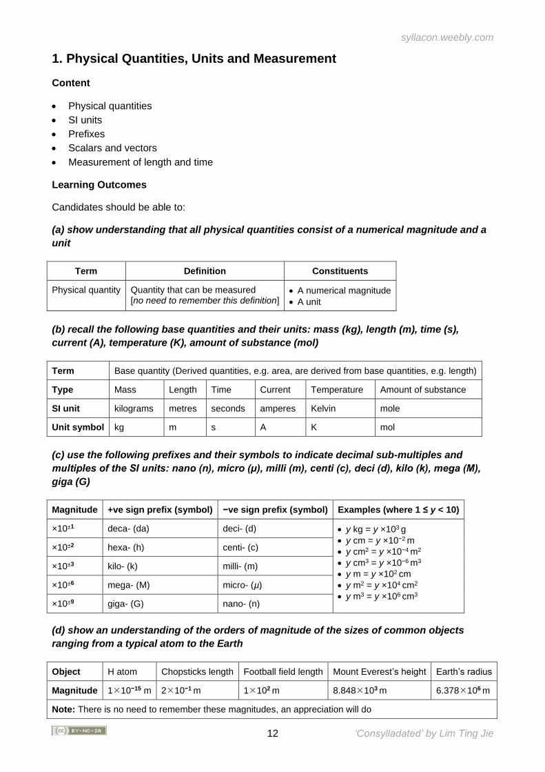
(a) show understanding that all physical quantities consist of a numerical magnitude and a
unit
Term Definition Constituents
Physical quantity Quantity that can be measured [no need to remember this definition]
• A numerical magnitude
• A unit
(b) recall the following base quantities and their units: mass (kg), length (m), time (s),
current (A), temperature (K), amount of substance (mol)
Term Base quantity (Derived quantities, e.g. area, are derived from base quantities, e.g. length)
Type Mass Length Time Current Temperature Amount of substance
SI unit kilograms metres seconds amperes Kelvin mole
Unit symbol kg m s A K mol
(c) use the following prefixes and their symbols to indicate decimal sub-multiples and
multiples of the SI units: nano (n), micro (μ), milli (m), centi (c), deci (d), kilo (k), mega (M),
giga (G)
Magnitude +ve sign prefix (symbol) −ve sign prefix (symbol) Examples (where 1 ≤ y < 10)
×10±1 deca- (da) deci- (d) • y kg = y ×103 g
• y cm = y ×10−2 m
• y cm2 = y ×10−4 m2
• y cm3 = y ×10−6 m3
• y m = y ×102 cm
• y m2 = y ×104 cm2
• y m3 = y ×106 cm3
×10±2 hexa- (h) centi- (c)
×10±3 kilo- (k) milli- (m)
×10±6 mega- (M) micro- (µ)
×10±9 giga- (G) nano- (n)
(d) show an understanding of the orders of magnitude of the sizes of common objects
ranging from a typical atom to the Earth
Object H atom Chopsticks length Football field length Mount Everest’s height Earth’s radius
Magnitude 110−15 m 210−1 m 1102 m 8.848103 m 6.378106 m
Note: There is no need to remember these magnitudes, an appreciation will do
syllacon.weebly.com
13 ‘Consylladated’ by Lim Ting Jie
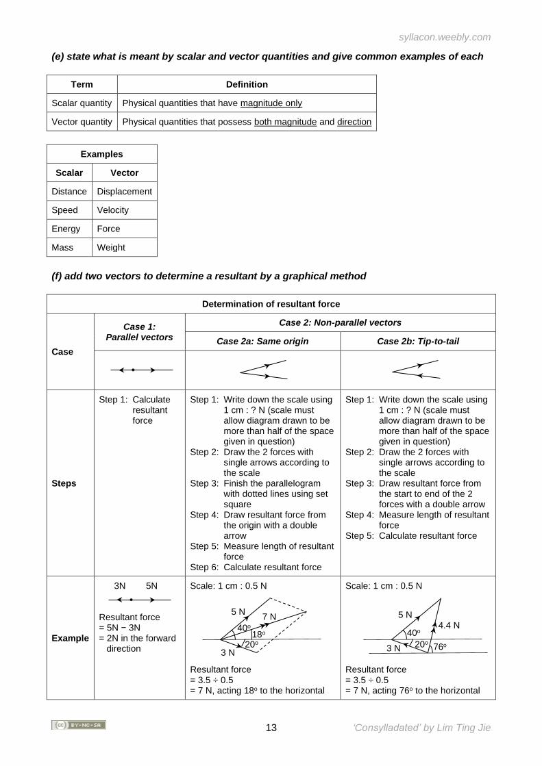
(e) state what is meant by scalar and vector quantities and give common examples of each
Term Definition
Scalar quantity Physical quantities that have magnitude only
Vector quantity Physical quantities that possess both magnitude and direction
Examples
Scalar Vector
Distance Displacement
Speed Velocity
Energy Force
Mass Weight
(f) add two vectors to determine a resultant by a graphical method
Determination of resultant force
Case
Case 1: Parallel vectors
Case 2: Non-parallel vectors
Case 2a: Same origin Case 2b: Tip-to-tail
Steps
Step 1: Calculate resultant force
Step 1: Write down the scale using 1 cm : ? N (scale must allow diagram drawn to be more than half of the space given in question)
Step 2: Draw the 2 forces with single arrows according to the scale
Step 3: Finish the parallelogram with dotted lines using set square
Step 4: Draw resultant force from the origin with a double arrow
Step 5: Measure length of resultant force
Step 6: Calculate resultant force
Step 1: Write down the scale using 1 cm : ? N (scale must allow diagram drawn to be more than half of the space given in question)
Step 2: Draw the 2 forces with single arrows according to the scale
Step 3: Draw resultant force from the start to end of the 2 forces with a double arrow
Step 4: Measure length of resultant force
Step 5: Calculate resultant force
Example
3N 5N Resultant force = 5N − 3N = 2N in the forward direction
Scale: 1 cm : 0.5 N Resultant force = 3.5 ÷ 0.5 = 7 N, acting 18o to the horizontal
Scale: 1 cm : 0.5 N Resultant force = 3.5 ÷ 0.5 = 7 N, acting 76o to the horizontal
5 N
3 N
7 N
40o 18o
20o
5 N
3 N
4.4 N 40o
20o 76o
syllacon.weebly.com
14 ‘Consylladated’ by Lim Ting Jie
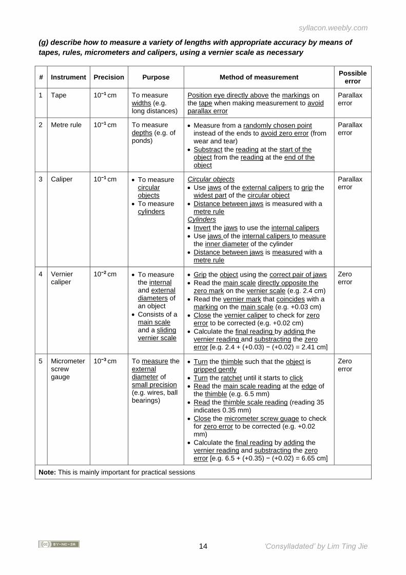
(g) describe how to measure a variety of lengths with appropriate accuracy by means of
tapes, rules, micrometers and calipers, using a vernier scale as necessary
# Instrument Precision Purpose Method of measurement Possible
error
1 Tape 10−1 cm To measure widths (e.g. long distances)
Position eye directly above the markings on the tape when making measurement to avoid parallax error
Parallax error
2 Metre rule 10−1 cm To measure depths (e.g. of ponds)
• Measure from a randomly chosen point instead of the ends to avoid zero error (from wear and tear)
• Substract the reading at the start of the object from the reading at the end of the object
Parallax error
3 Caliper 10−1 cm • To measure circular objects
• To measure cylinders
Circular objects
• Use jaws of the external calipers to grip the widest part of the circular object
• Distance between jaws is measured with a metre rule
Cylinders
• Invert the jaws to use the internal calipers
• Use jaws of the internal calipers to measure the inner diameter of the cylinder
• Distance between jaws is measured with a metre rule
Parallax error
4 Vernier caliper
10−2 cm • To measure the internal and external diameters of an object
• Consists of a main scale and a sliding vernier scale
• Grip the object using the correct pair of jaws
• Read the main scale directly opposite the zero mark on the vernier scale (e.g. 2.4 cm)
• Read the vernier mark that coincides with a marking on the main scale (e.g. +0.03 cm)
• Close the vernier caliper to check for zero error to be corrected (e.g. +0.02 cm)
• Calculate the final reading by adding the vernier reading and substracting the zero error [e.g. 2.4 + (+0.03) − (+0.02) = 2.41 cm]
Zero error
5 Micrometer screw gauge
10−3 cm To measure the external diameter of small precision (e.g. wires, ball bearings)
• Turn the thimble such that the object is gripped gently
• Turn the ratchet until it starts to click
• Read the main scale reading at the edge of the thimble (e.g. 6.5 mm)
• Read the thimble scale reading (reading 35 indicates 0.35 mm)
• Close the micrometer screw guage to check for zero error to be corrected (e.g. +0.02 mm)
• Calculate the final reading by adding the vernier reading and substracting the zero error [e.g. 6.5 + (+0.35) − (+0.02) = 6.65 cm]
Zero error
Note: This is mainly important for practical sessions
syllacon.weebly.com
15 ‘Consylladated’ by Lim Ting Jie
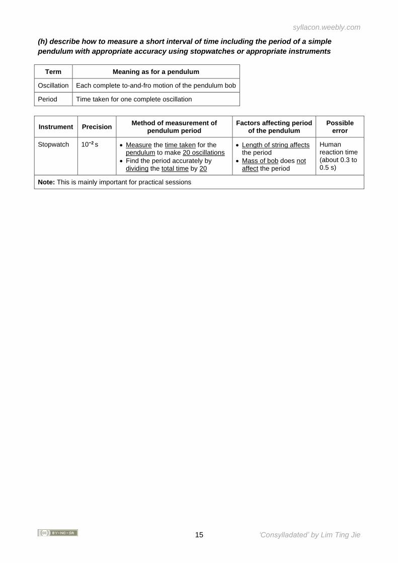
(h) describe how to measure a short interval of time including the period of a simple
pendulum with appropriate accuracy using stopwatches or appropriate instruments
Term Meaning as for a pendulum
Oscillation Each complete to-and-fro motion of the pendulum bob
Period Time taken for one complete oscillation
Instrument Precision Method of measurement of
pendulum period Factors affecting period
of the pendulum Possible
error
Stopwatch 10−2 s • Measure the time taken for the pendulum to make 20 oscillations
• Find the period accurately by dividing the total time by 20
• Length of string affects the period
• Mass of bob does not affect the period
Human reaction time (about 0.3 to 0.5 s)
Note: This is mainly important for practical sessions
syllacon.weebly.com
16 ‘Consylladated’ by Lim Ting Jie
SECTION II: NEWTONIAN MECHANICS
Overview Mechanics is the branch of physics that deals with the study of motion and its causes. Through a careful process of observation and experimentation, Galileo Galilei used experiments to overturn Aristotle’s ideas of the motion of objects, for example the flawed idea that heavy objects fall faster than lighter ones, which dominated physics for about 2,000 years. The greatest contribution to the development of mechanics is by one of the greatest physicists of all time, Isaac Newton. By extending Galileo’s methods and understanding of motion and gravitation, Newton developed the three laws of motion and his law of universal gravitation, and successfully applied them to both terrestrial and celestial systems to predict and explain phenomena. He showed that nature is governed by a few special rules or laws that can be expressed in mathematical formulae. Newton’s combination of logical experimentation and mathematical analysis shaped the way science has been done ever since. In this section, we begin by examining kinematics, which is a study of motion without regard for the cause. After which, we study the conditions required for an object to be accelerated and introduce the concept of forces through Newton’s Laws. Subsequently, concepts of moments and pressure are introduced as consequences of a force. Finally, this section rounds up by leading the discussion from force to work and energy, and the use of the principle of conservation of energy to explain interactions between bodies.
Extracted from PHYSICS GCE ORDINARY LEVEL (2014) Syllabus Document
syllacon.weebly.com
17 ‘Consylladated’ by Lim Ting Jie
2. Kinematics
Content
• Speed, velocity and acceleration
• Graphical analysis of motion
• Free-fall
• Effect of air resistance
Learning Outcomes
Candidates should be able to:
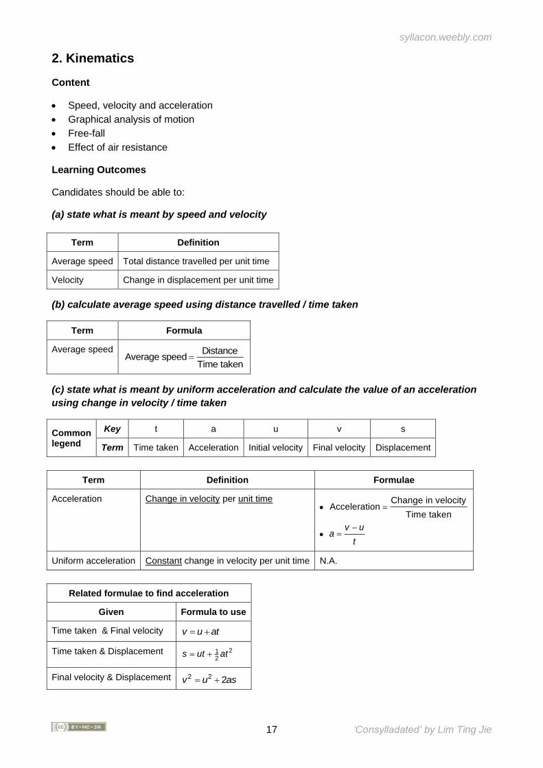
(a) state what is meant by speed and velocity
Term Definition
Average speed Total distance travelled per unit time
Velocity Change in displacement per unit time
(b) calculate average speed using distance travelled / time taken
Term Formula
Average speed DistanceAverage speed
Time taken=
(c) state what is meant by uniform acceleration and calculate the value of an acceleration
using change in velocity / time taken
Common legend
Key t a u v s
Term Time taken Acceleration Initial velocity Final velocity Displacement
Term Definition Formulae
Acceleration Change in velocity per unit time •
Change in velocityAcceleration
Time taken=
• v u
at
−=
Uniform acceleration Constant change in velocity per unit time N.A.
Related formulae to find acceleration
Given Formula to use
Time taken & Final velocity v u at= +
Time taken & Displacement 212
s ut at= +
Final velocity & Displacement 2 2 2v u as= +
syllacon.weebly.com
18 ‘Consylladated’ by Lim Ting Jie
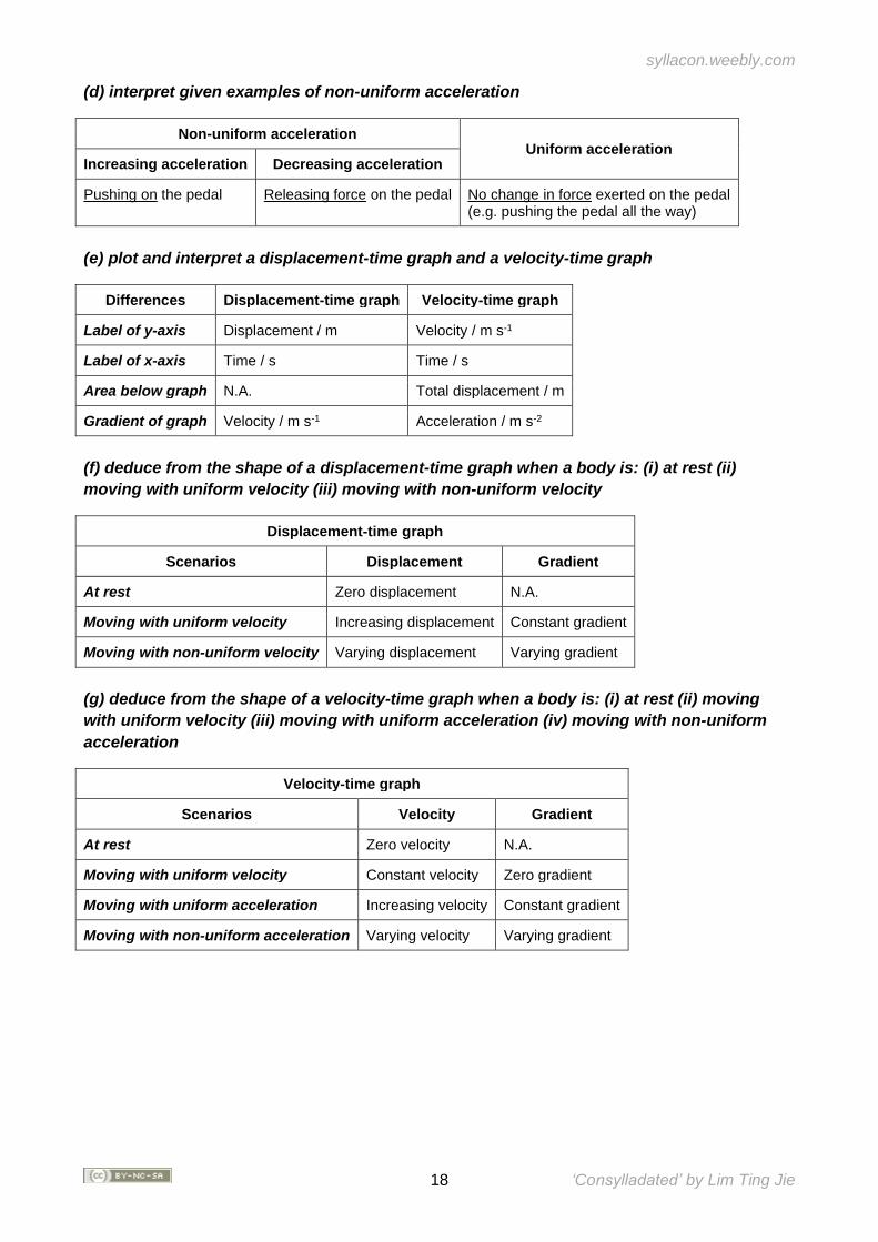
(d) interpret given examples of non-uniform acceleration
Non-uniform acceleration Uniform acceleration
Increasing acceleration Decreasing acceleration
Pushing on the pedal Releasing force on the pedal No change in force exerted on the pedal (e.g. pushing the pedal all the way)
(e) plot and interpret a displacement-time graph and a velocity-time graph
Differences Displacement-time graph Velocity-time graph
Label of y-axis Displacement / m Velocity / m s-1
Label of x-axis Time / s Time / s
Area below graph N.A. Total displacement / m
Gradient of graph Velocity / m s-1 Acceleration / m s-2
(f) deduce from the shape of a displacement-time graph when a body is: (i) at rest (ii)
moving with uniform velocity (iii) moving with non-uniform velocity
Displacement-time graph
Scenarios Displacement Gradient
At rest Zero displacement N.A.
Moving with uniform velocity Increasing displacement Constant gradient
Moving with non-uniform velocity Varying displacement Varying gradient
(g) deduce from the shape of a velocity-time graph when a body is: (i) at rest (ii) moving
with uniform velocity (iii) moving with uniform acceleration (iv) moving with non-uniform
acceleration
Velocity-time graph
Scenarios Velocity Gradient
At rest Zero velocity N.A.
Moving with uniform velocity Constant velocity Zero gradient
Moving with uniform acceleration Increasing velocity Constant gradient
Moving with non-uniform acceleration Varying velocity Varying gradient
syllacon.weebly.com
19 ‘Consylladated’ by Lim Ting Jie
(h) calculate the area under a velocity-time graph to determine the displacement travelled
for motion with uniform velocity or uniform acceleration
Term Formulae
Displacement Displacement Area under velocity-time graph=
Area of square Velocity Time taken=
12
Area of triangle Velocity Time taken=
Term Formulae in symbols
Displacement ( )( )12
s v u t= +
Average velocity ( )12
Average velocity v u= +
(i) state that the acceleration of free fall for a body near to the Earth is constant and is
approximately 10 m/s2
Relationship between force and acceleration
• When a force is exerted on an object, the object will experience constant acceleration in the direction of the force if there is no other force acting against it (i.e. constant resultant force)
• Any free falling object near to the Earth will experience constant acceleration of approximately 10 m/s2 due to gravity as there is no air resistance acting against it
• Acceleration will only decrease when the object enters Earth as it will then experience air resistance
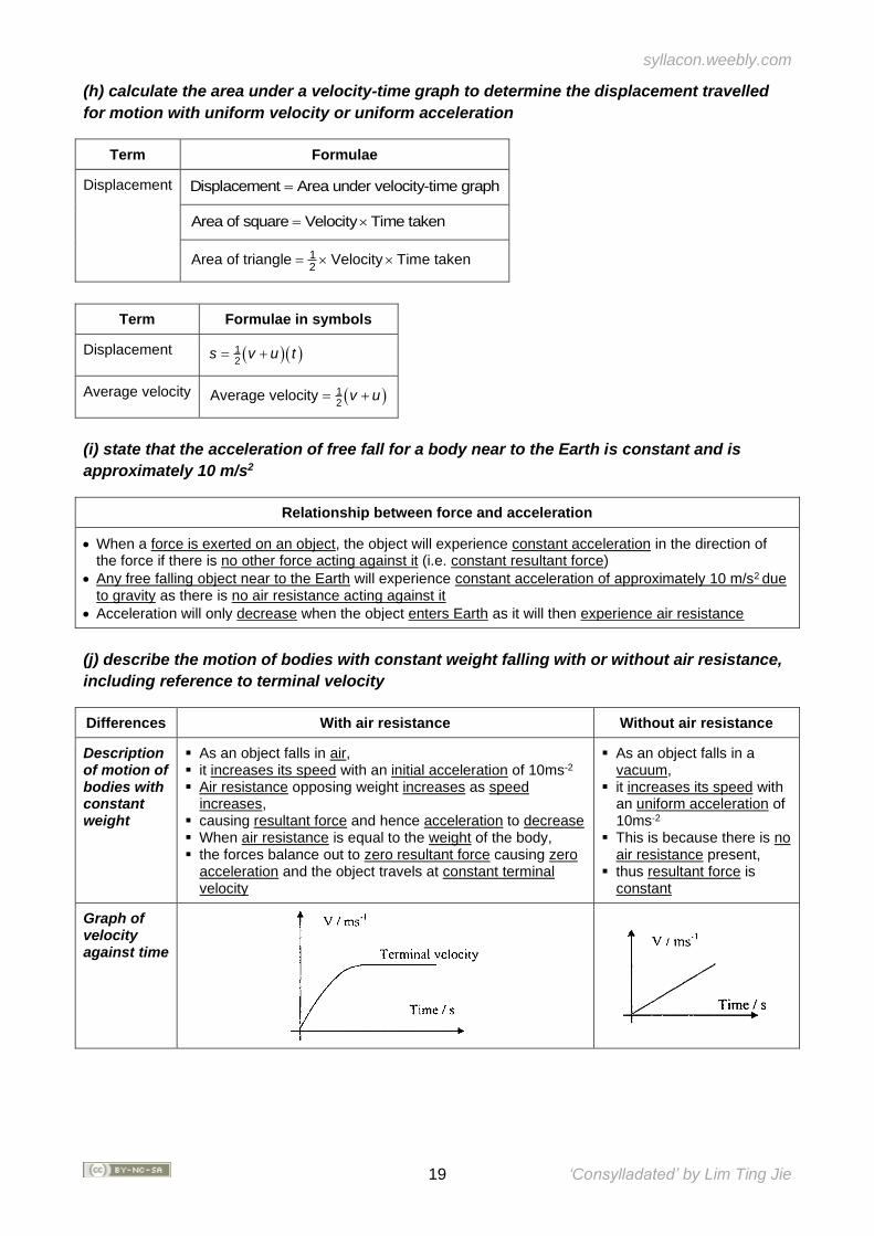
(j) describe the motion of bodies with constant weight falling with or without air resistance,
including reference to terminal velocity
Differences With air resistance Without air resistance
Description of motion of bodies with constant weight
▪ As an object falls in air, ▪ it increases its speed with an initial acceleration of 10ms-2 ▪ Air resistance opposing weight increases as speed
increases, ▪ causing resultant force and hence acceleration to decrease ▪ When air resistance is equal to the weight of the body, ▪ the forces balance out to zero resultant force causing zero
acceleration and the object travels at constant terminal velocity
▪ As an object falls in a vacuum,
▪ it increases its speed with an uniform acceleration of 10ms-2
▪ This is because there is no air resistance present,
▪ thus resultant force is constant
Graph of velocity against time
syllacon.weebly.com
20 ‘Consylladated’ by Lim Ting Jie
3. Dynamics
Content
• Balanced and unbalanced forces
• Free-body diagram
• Friction
Learning Outcomes
Candidates should be able to:
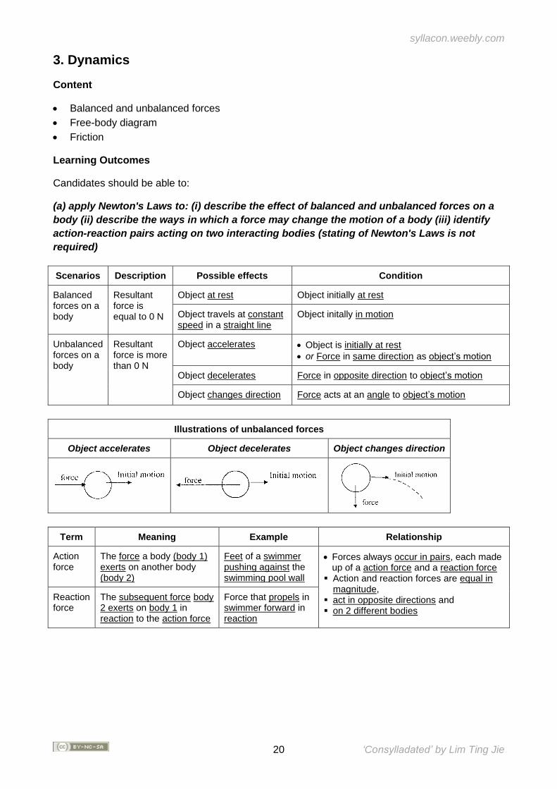
(a) apply Newton's Laws to: (i) describe the effect of balanced and unbalanced forces on a
body (ii) describe the ways in which a force may change the motion of a body (iii) identify
action-reaction pairs acting on two interacting bodies (stating of Newton's Laws is not
required)
Scenarios Description Possible effects Condition
Balanced forces on a body
Resultant force is equal to 0 N
Object at rest Object initially at rest
Object travels at constant speed in a straight line
Object initally in motion
Unbalanced forces on a body
Resultant force is more than 0 N
Object accelerates • Object is initially at rest
• or Force in same direction as object’s motion
Object decelerates Force in opposite direction to object’s motion
Object changes direction Force acts at an angle to object’s motion
Illustrations of unbalanced forces
Object accelerates Object decelerates Object changes direction
Term Meaning Example Relationship
Action force
The force a body (body 1) exerts on another body (body 2)
Feet of a swimmer pushing against the swimming pool wall
• Forces always occur in pairs, each made up of a action force and a reaction force
▪ Action and reaction forces are equal in magnitude,
▪ act in opposite directions and ▪ on 2 different bodies
Reaction force
The subsequent force body 2 exerts on body 1 in reaction to the action force
Force that propels in swimmer forward in reaction
syllacon.weebly.com
21 ‘Consylladated’ by Lim Ting Jie
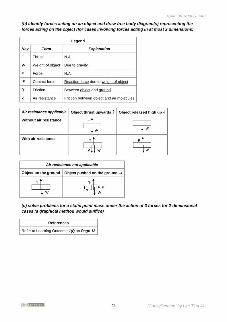
(b) identify forces acting on an object and draw free body diagram(s) representing the
forces acting on the object (for cases involving forces acting in at most 2 dimensions)
Legend
Key Term Explanation
T Thrust N.A.
W Weight of object Due to gravity
F Force N.A.
+F Contact force Reaction force due to weight of object
*f Friction Between object and ground
R Air resistance Friction between object and air molecules
Air resistance applicable Object thrust upwards Object released high up
Without air resistance
With air resistance
Air resistance not applicable
Object on the ground Object pushed on the ground →
(c) solve problems for a static point mass under the action of 3 forces for 2-dimensional
cases (a graphical method would suffice)
References
Refer to Learning Outcome 1(f) on Page 13
syllacon.weebly.com
22 ‘Consylladated’ by Lim Ting Jie
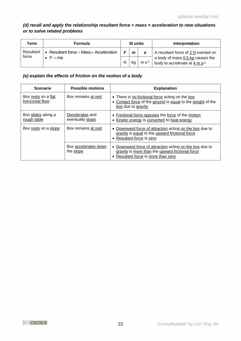
(d) recall and apply the relationship resultant force = mass × acceleration to new situations
or to solve related problems
Term Formula SI units Interpretation
Resultant force
• Resultant force Mass Acceleration=
• F ma=
F m a A resultant force of 2 N exerted on
a body of mass 0.5 kg causes the
body to accelerate at 4 m s-2 N kg m s-2
(e) explain the effects of friction on the motion of a body
Scenario Possible motions Explanation
Box rests on a flat horizontal floor
Box remains at rest • There is no frictional force acting on the box
• Contact force of the ground is equal to the weight of the box due to gravity
Box slides along a rough table
Decelerates and eventually stops
• Frictional force opposes the force of the motion
• Kinetic energy is converted to heat energy
Box rests on a slope Box remains at rest • Downward force of attraction acting on the box due to gravity is equal to the upward frictional force
• Resultant force is zero
Box accelerates down the slope
• Downward force of attraction acting on the box due to gravity is more than the upward frictional force
• Resultant force is more than zero
syllacon.weebly.com
23 ‘Consylladated’ by Lim Ting Jie
4. Mass, Weight and Density
Content
• Mass and weight
• Gravitational field and field strength
• Density
Learning Outcomes
Candidates should be able to:
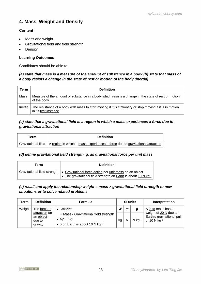
(a) state that mass is a measure of the amount of substance in a body (b) state that mass of
a body resists a change in the state of rest or motion of the body (inertia)
Term Definition
Mass Measure of the amount of substance in a body which resists a change in the state of rest or motion of the body
Inertia The resistance of a body with mass to start moving if it is stationary or stop moving if it is in motion in its first instance
(c) state that a gravitational field is a region in which a mass experiences a force due to
gravitational attraction
Term Definition
Gravitational field A region in which a mass experiences a force due to gravitational attraction
(d) define gravitational field strength, g, as gravitational force per unit mass
Term Definition
Gravitational field strength • Gravitational force acting per unit mass on an object
• The gravitational field strength on Earth is about 10 N kg-1
(e) recall and apply the relationship weight = mass × gravitational field strength to new
situations or to solve related problems
Term Definition Formula SI units Interpretation
Weight The force of attraction on an object due to gravity
• Weight
Mass Gravitational field strength=
• W mg=
• g on Earth is about 10 N kg-1
W m g A 2 kg mass has a weight of 20 N due to Earth’s gravitational pull of 10 N kg-1 kg N N kg-1
syllacon.weebly.com
24 ‘Consylladated’ by Lim Ting Jie
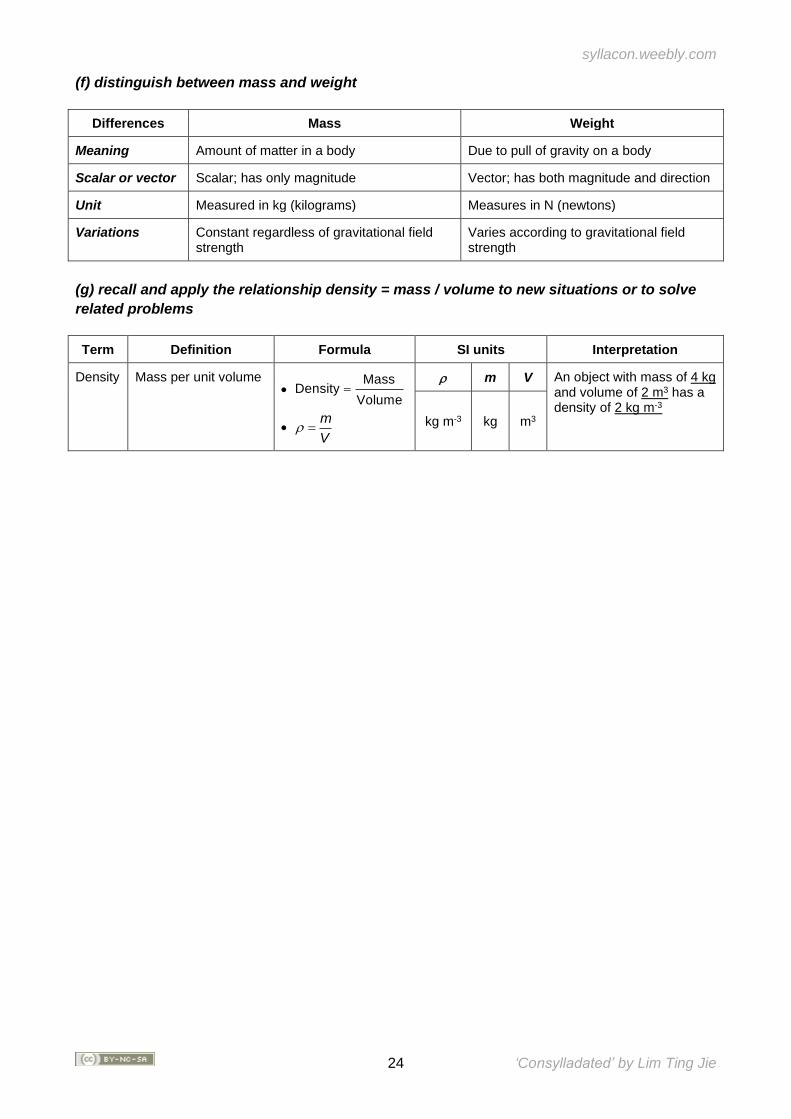
(f) distinguish between mass and weight
Differences Mass Weight
Meaning Amount of matter in a body Due to pull of gravity on a body
Scalar or vector Scalar; has only magnitude Vector; has both magnitude and direction
Unit Measured in kg (kilograms) Measures in N (newtons)
Variations Constant regardless of gravitational field strength
Varies according to gravitational field strength
(g) recall and apply the relationship density = mass / volume to new situations or to solve
related problems
Term Definition Formula SI units Interpretation
Density Mass per unit volume •
MassDensity
Volume=
• m
V =
m V An object with mass of 4 kg and volume of 2 m3 has a density of 2 kg m-3
kg m-3 kg m3
syllacon.weebly.com
25 ‘Consylladated’ by Lim Ting Jie
5. Turning Effect of Forces
Content
• Moments
• Centre of gravity
• Stability
Learning Outcomes
Candidates should be able to:
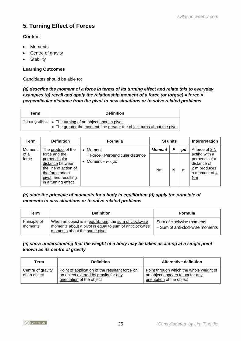
(a) describe the moment of a force in terms of its turning effect and relate this to everyday
examples (b) recall and apply the relationship moment of a force (or torque) = force ×
perpendicular distance from the pivot to new situations or to solve related problems
Term Definition
Turning effect • The turning of an object about a pivot
• The greater the moment, the greater the object turns about the pivot
Term Definition Formula SI units Interpretation
Moment of a force
The product of the force and the perpendicular distance between the line of action of the force and a pivot, and resulting in a turning effect
• Moment
Force Perpendicular distance=
• Moment F pd=
Moment F pd A force of 2 N acting with a perpendicular distance of 2 m produces a moment of 4 Nm
Nm N m
(c) state the principle of moments for a body in equilibrium (d) apply the principle of
moments to new situations or to solve related problems
Term Definition Formula
Principle of moments
When an object is in equilibrium, the sum of clockwise moments about a pivot is equal to sum of anticlockwise moments about the same pivot
Sum of clockwise moments Sum of anti-clockwise moments=
(e) show understanding that the weight of a body may be taken as acting at a single point
known as its centre of gravity
Term Definition Alternative definition
Centre of gravity of an object
Point of application of the resultant force on an object exerted by gravity for any orientation of the object
Point through which the whole weight of an object appears to act for any orientation of the object

syllacon.weebly.com
26 ‘Consylladated’ by Lim Ting Jie
(f) describe qualitatively the effect of the position of the centre of gravity on the stability of
objects
Scenario Effect on stability Measure to increase stability
Higher centre of gravity • Lower stability of the object
• Toppling will occur at smaller angles of tilt
Decrease the centre of gravity by adding more mass below the current centre of gravity to the object
Object is tilted such that centre of gravity is still vertically above the base of object
Object will not topple Increase the size of base
Object is tilted such that centre of gravity is no longer vertically above the base of object
Object will topple
syllacon.weebly.com
27 ‘Consylladated’ by Lim Ting Jie
6. Pressure
Content
• Pressure
• Pressure differences
• Pressure measurement
Learning Outcomes
Candidates should be able to:
(a) define the term pressure in terms of force and area (b) recall and apply the relationship
pressure = force / area to new situations or to solve related problems
Term Definition Formula SI units Interpretation
Pressure Average force per unit area •
ForcePressure
Area=
• F
p =A
p F A A force of 4 N acting on an area of 2 m2 results in a pressure of 2 Pa
Pa or N m-2 N m2
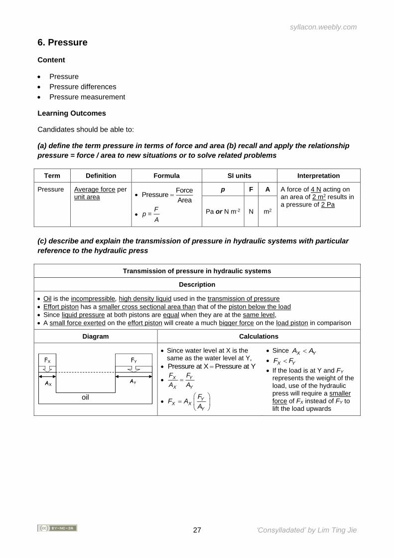
(c) describe and explain the transmission of pressure in hydraulic systems with particular
reference to the hydraulic press
Transmission of pressure in hydraulic systems
Description
• Oil is the incompressible, high density liquid used in the transmission of pressure
• Effort piston has a smaller cross sectional area than that of the piston below the load
• Since liquid pressure at both pistons are equal when they are at the same level,
• A small force exerted on the effort piston will create a much bigger force on the load piston in comparison
Diagram Calculations
• Since water level at X is the same as the water level at Y,
• Pressure at X Pressure at Y=
• X Y
X Y
F F
A A=
• YX X
Y
FF A
A
=
• Since X YA A
• X YF F
• If the load is at Y and FY represents the weight of the load, use of the hydraulic press will require a smaller force of FX instead of FY to lift the load upwards
oil
syllacon.weebly.com
28 ‘Consylladated’ by Lim Ting Jie
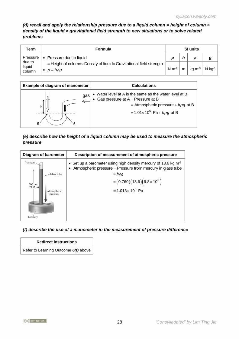
(d) recall and apply the relationship pressure due to a liquid column = height of column ×
density of the liquid × gravitational field strength to new situations or to solve related
problems
Term Formula SI units
Pressure due to liquid column
• Pressure due to liquid
Height of column Density of liquid Gravitational field strength=
• p h g=
p h g
N m-2 m kg m-3 N kg-1
Example of diagram of manometer Calculations
• Water level at A is the same as the water level at B
• Gas pressure at A Pressure at B=
5
Atmospheric pressure at B
1.01 10 Pa at B
= +
= +
h g
h g
(e) describe how the height of a liquid column may be used to measure the atmospheric
pressure
Diagram of barometer Description of measurement of atmospheric pressure
• Set up a barometer using high density mercury of 13.6 kg m-3
• Atmospheric pressure Pressure from mercury in glass tube=
( ) ( ) ( )3
5
0.760 13.6 9.8 10
1.013 10 Pa
=
=
=
h g
(f) describe the use of a manometer in the measurement of pressure difference
Redirect instructions
Refer to Learning Outcome 6(f) above
gas
syllacon.weebly.com
29 ‘Consylladated’ by Lim Ting Jie
7. Energy, Work and Power
Content
• Energy conversion and conservation
• Work
• Power
Learning Outcomes
Candidates should be able to:
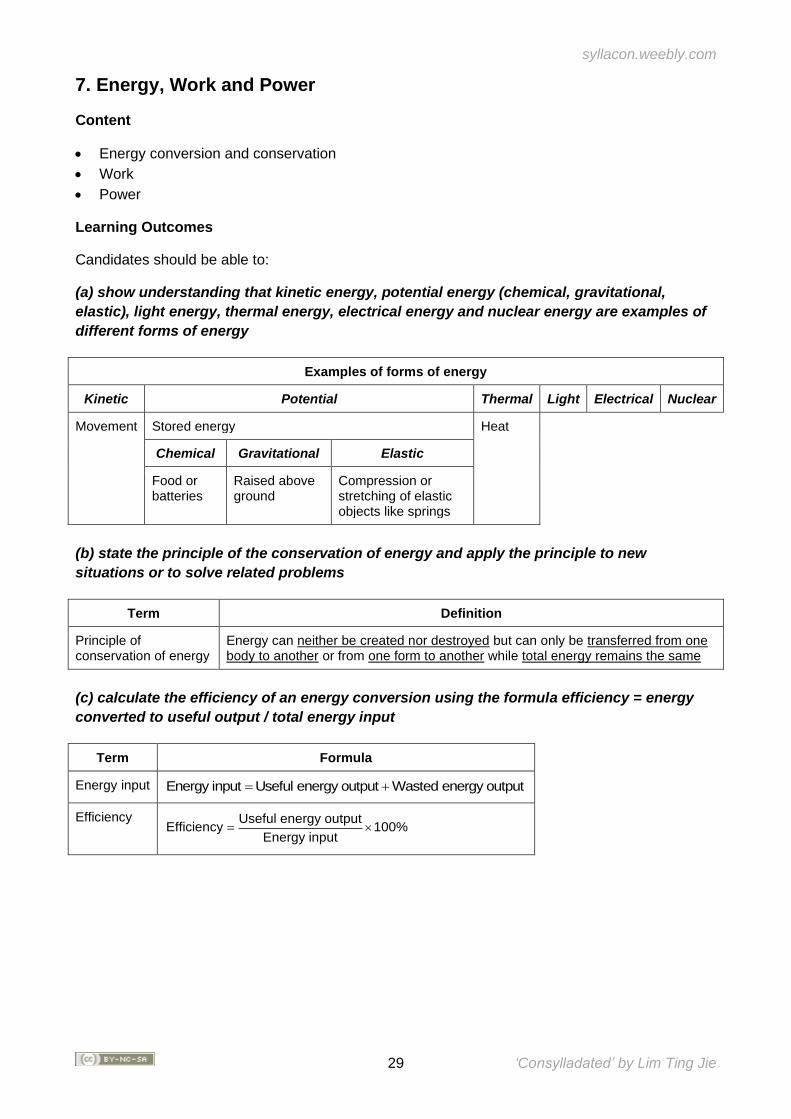
(a) show understanding that kinetic energy, potential energy (chemical, gravitational,
elastic), light energy, thermal energy, electrical energy and nuclear energy are examples of
different forms of energy
Examples of forms of energy
Kinetic Potential Thermal Light Electrical Nuclear
Movement Stored energy Heat
Chemical Gravitational Elastic
Food or batteries
Raised above ground
Compression or stretching of elastic objects like springs
(b) state the principle of the conservation of energy and apply the principle to new
situations or to solve related problems
Term Definition
Principle of conservation of energy
Energy can neither be created nor destroyed but can only be transferred from one body to another or from one form to another while total energy remains the same
(c) calculate the efficiency of an energy conversion using the formula efficiency = energy
converted to useful output / total energy input
Term Formula
Energy input Useful energy output Wasted En energy inp ergy ou uut tp t= +
Efficiency Useful energy outputEfficiency 100%
Energy input=
syllacon.weebly.com
30 ‘Consylladated’ by Lim Ting Jie
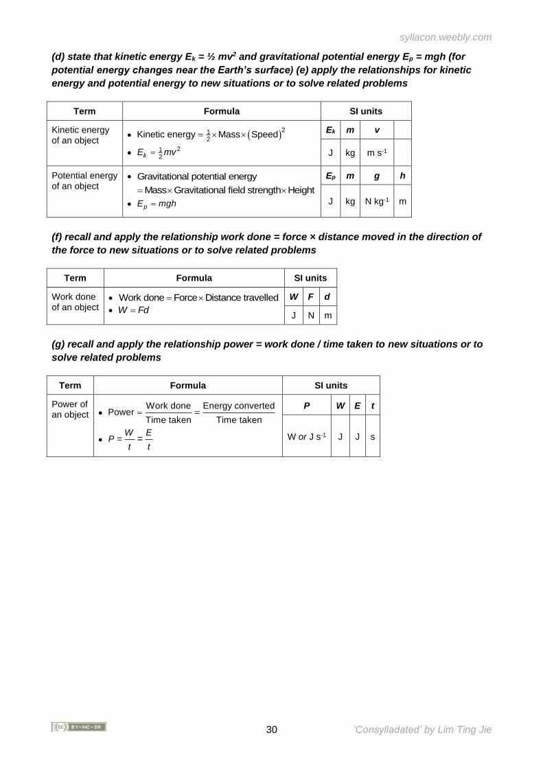
(d) state that kinetic energy Ek = ½ mv2 and gravitational potential energy Ep = mgh (for
potential energy changes near the Earth’s surface) (e) apply the relationships for kinetic
energy and potential energy to new situations or to solve related problems
Term Formula SI units
Kinetic energy of an object
• ( )21
2Kinetic energy Mass Speed=
• 21
2kE mv=
Ek m v
J kg m s-1
Potential energy of an object
• Gravitational potential energy
Mass Gravitational field strength Height=
• pE mgh=
Ep m g h
J kg N kg-1 m
(f) recall and apply the relationship work done = force × distance moved in the direction of
the force to new situations or to solve related problems
Term Formula SI units
Work done of an object
• Force DistanceWork travdo e en de ll=
• W Fd=
W F d
J N m
(g) recall and apply the relationship power = work done / time taken to new situations or to
solve related problems
Term Formula SI units
Power of an object •
Work done Energy converted
Time taken TimeP
owe
enr
tak= =
• PW E
=t t
=
P W E t
W or J s-1 J J s
syllacon.weebly.com
31 ‘Consylladated’ by Lim Ting Jie
SECTION III: THERMAL PHYSICS
Overview Amongst the early scientists, heat was thought as some kind of invisible, massless fluid called ‘caloric’. Certain objects that released heat upon combustion were thought to be able to ‘store’ the fluid. However, this explanation failed to explain why friction was able to produce heat. In the 1840s, James Prescott Joule used a falling weight to drive an electrical generator that heated a wire immersed in water. This experiment demonstrated that work done by a falling object could be converted to heat. In the previous section, we studied about energy and its conversion. Many energy conversion processes which involve friction will have heat as a product. This section begins with the introduction of the kinetic model of matter. This model is then used to explain and predict the physical properties and changes of matter at the molecular level in relation to heat or thermal energy transfer.
Extracted from PHYSICS GCE ORDINARY LEVEL (2014) Syllabus Document
syllacon.weebly.com
32 ‘Consylladated’ by Lim Ting Jie
8. Kinetic Model of Matter
Content
• States of matter
• Brownian motion
• Kinetic model
Learning Outcomes
Candidates should be able to:
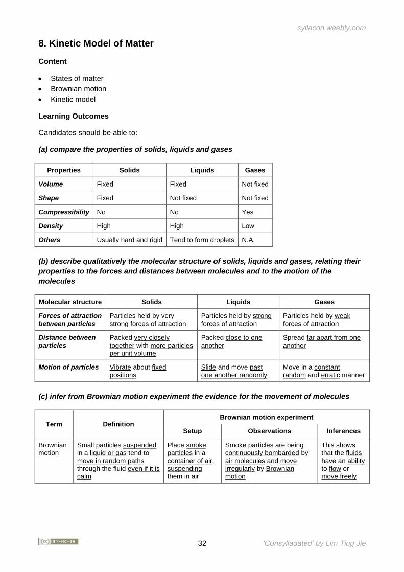
(a) compare the properties of solids, liquids and gases
Properties Solids Liquids Gases
Volume Fixed Fixed Not fixed
Shape Fixed Not fixed Not fixed
Compressibility No No Yes
Density High High Low
Others Usually hard and rigid Tend to form droplets N.A.
(b) describe qualitatively the molecular structure of solids, liquids and gases, relating their
properties to the forces and distances between molecules and to the motion of the
molecules
Molecular structure Solids Liquids Gases
Forces of attraction between particles
Particles held by very strong forces of attraction
Particles held by strong forces of attraction
Particles held by weak forces of attraction
Distance between particles
Packed very closely together with more particles per unit volume
Packed close to one another
Spread far apart from one another
Motion of particles Vibrate about fixed positions
Slide and move past one another randomly
Move in a constant, random and erratic manner
(c) infer from Brownian motion experiment the evidence for the movement of molecules
Term Definition Brownian motion experiment
Setup Observations Inferences
Brownian motion
Small particles suspended in a liquid or gas tend to move in random paths through the fluid even if it is calm
Place smoke particles in a container of air, suspending them in air
Smoke particles are being continuously bombarded by air molecules and move irregularly by Brownian motion
This shows that the fluids have an ability to flow or move freely
syllacon.weebly.com
33 ‘Consylladated’ by Lim Ting Jie
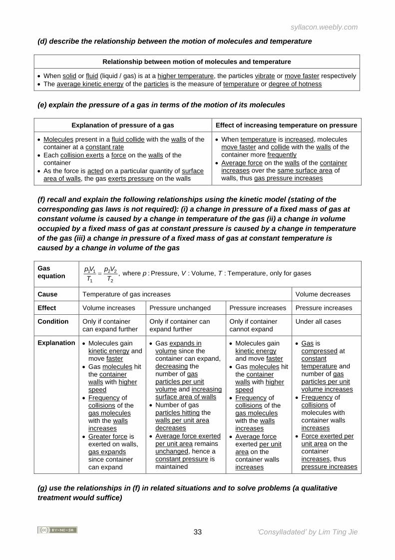
(d) describe the relationship between the motion of molecules and temperature
Relationship between motion of molecules and temperature
• When solid or fluid (liquid / gas) is at a higher temperature, the particles vibrate or move faster respectively
• The average kinetic energy of the particles is the measure of temperature or degree of hotness
(e) explain the pressure of a gas in terms of the motion of its molecules
Explanation of pressure of a gas Effect of increasing temperature on pressure
• Molecules present in a fluid collide with the walls of the container at a constant rate
• Each collision exerts a force on the walls of the container
• As the force is acted on a particular quantity of surface area of walls, the gas exerts pressure on the walls
• When temperature is increased, molecules move faster and collide with the walls of the container more frequently
• Average force on the walls of the container increases over the same surface area of walls, thus gas pressure increases
(f) recall and explain the following relationships using the kinetic model (stating of the
corresponding gas laws is not required): (i) a change in pressure of a fixed mass of gas at
constant volume is caused by a change in temperature of the gas (ii) a change in volume
occupied by a fixed mass of gas at constant pressure is caused by a change in temperature
of the gas (iii) a change in pressure of a fixed mass of gas at constant temperature is
caused by a change in volume of the gas
Gas equation
1 1 2 2
1 2
, where : Pressure, : Volume, : Temperature, only for gasesp V p V
p V TT T
=
Cause Temperature of gas increases Volume decreases
Effect Volume increases Pressure unchanged Pressure increases Pressure increases
Condition Only if container can expand further
Only if container can expand further
Only if container cannot expand
Under all cases
Explanation • Molecules gain kinetic energy and move faster
• Gas molecules hit the container walls with higher speed
• Frequency of collisions of the gas molecules with the walls increases
• Greater force is exerted on walls, gas expands since container can expand
• Gas expands in volume since the container can expand, decreasing the number of gas particles per unit volume and increasing surface area of walls
• Number of gas particles hitting the walls per unit area decreases
• Average force exerted per unit area remains unchanged, hence a constant pressure is maintained
• Molecules gain kinetic energy and move faster
• Gas molecules hit the container walls with higher speed
• Frequency of collisions of the gas molecules with the walls increases
• Average force exerted per unit area on the container walls increases
• Gas is compressed at constant temperature and number of gas particles per unit volume increases
• Frequency of collisions of molecules with container walls increases
• Force exerted per unit area on the container increases, thus pressure increases
(g) use the relationships in (f) in related situations and to solve problems (a qualitative
treatment would suffice)
syllacon.weebly.com
34 ‘Consylladated’ by Lim Ting Jie
9. Transfer of Thermal Energy
Content
• Conduction
• Convection
• Radiation
Learning Outcomes
Candidates should be able to:
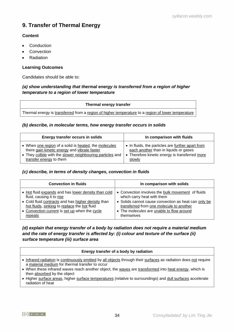
(a) show understanding that thermal energy is transferred from a region of higher
temperature to a region of lower temperature
Thermal energy transfer
Thermal energy is transferred from a region of higher temperature to a region of lower temperature
(b) describe, in molecular terms, how energy transfer occurs in solids
Energy transfer occurs in solids In comparison with fluids
• When one region of a solid is heated, the molecules there gain kinetic energy and vibrate faster
• They collide with the slower neighbouring particles and transfer energy to them
• In fluids, the particles are further apart from each another than in liquids or gases
• Therefore kinetic energy is transferred more slowly
(c) describe, in terms of density changes, convection in fluids
Convection in fluids In comparison with solids
• Hot fluid expands and has lower density than cold fluid, causing it to rise
• Cold fluid contracts and has higher density than hot fluids, sinking to replace the hot fluid
• Convection current is set up when the cycle repeats
• Convection involves the bulk movement of fluids which carry heat with them
• Solids cannot cause convection as heat can only be transferred from one molecule to another
• The molecules are unable to flow around themselves
(d) explain that energy transfer of a body by radiation does not require a material medium
and the rate of energy transfer is affected by: (i) colour and texture of the surface (ii)
surface temperature (iii) surface area
Energy transfer of a body by radiation
• Infrared radiation is continuously emitted by all objects through their surfaces as radiation does not require a material medium for thermal transfer to occur
• When these infrared waves reach another object, the waves are transformed into heat energy, which is then absorbed by the object
• Higher surface areas, higher surface temperatures (relative to surroundings) and dull surfaces accelerate radiation of heat
syllacon.weebly.com
35 ‘Consylladated’ by Lim Ting Jie
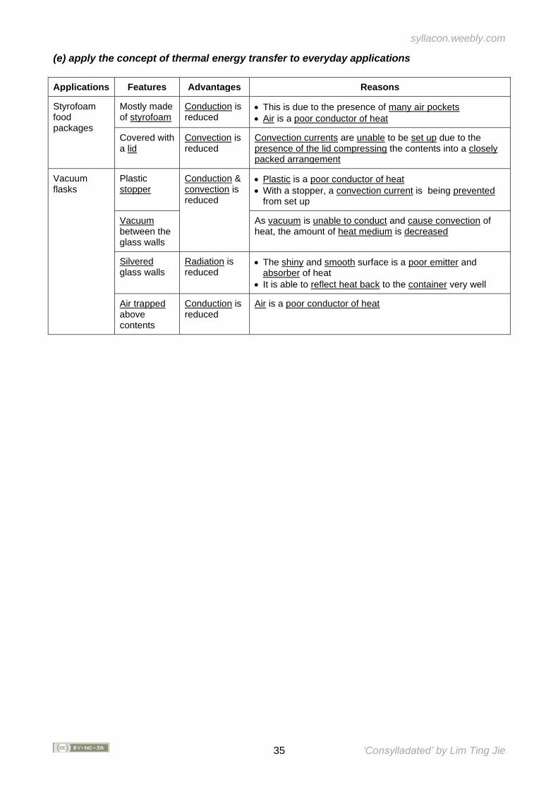
(e) apply the concept of thermal energy transfer to everyday applications
Applications Features Advantages Reasons
Styrofoam food packages
Mostly made of styrofoam
Conduction is reduced
• This is due to the presence of many air pockets
• Air is a poor conductor of heat
Covered with a lid
Convection is reduced
Convection currents are unable to be set up due to the presence of the lid compressing the contents into a closely packed arrangement
Vacuum flasks
Plastic stopper
Conduction & convection is reduced
• Plastic is a poor conductor of heat
• With a stopper, a convection current is being prevented from set up
Vacuum between the glass walls
As vacuum is unable to conduct and cause convection of heat, the amount of heat medium is decreased
Silvered glass walls
Radiation is reduced
• The shiny and smooth surface is a poor emitter and absorber of heat
• It is able to reflect heat back to the container very well
Air trapped above contents
Conduction is reduced
Air is a poor conductor of heat
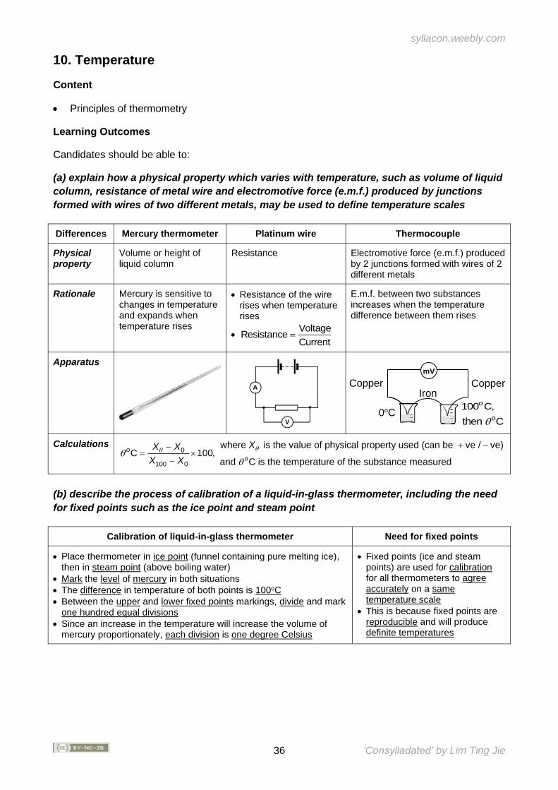
syllacon.weebly.com
36 ‘Consylladated’ by Lim Ting Jie
10. Temperature
Content
• Principles of thermometry
Learning Outcomes
Candidates should be able to:
(a) explain how a physical property which varies with temperature, such as volume of liquid
column, resistance of metal wire and electromotive force (e.m.f.) produced by junctions
formed with wires of two different metals, may be used to define temperature scales
Differences Mercury thermometer Platinum wire Thermocouple
Physical property
Volume or height of liquid column
Resistance Electromotive force (e.m.f.) produced by 2 junctions formed with wires of 2 different metals
Rationale Mercury is sensitive to changes in temperature and expands when temperature rises
• Resistance of the wire rises when temperature rises
• Voltage
ResistanceCurrent
=
E.m.f. between two substances increases when the temperature difference between them rises
Apparatus
Calculations 0
100 0
where is the value of physical property used (can be ve / ve)C 100,
and C is the temperature of the substance measured
o
o
XX X
X X
+ −−=
−
(b) describe the process of calibration of a liquid-in-glass thermometer, including the need
for fixed points such as the ice point and steam point
Calibration of liquid-in-glass thermometer Need for fixed points
• Place thermometer in ice point (funnel containing pure melting ice), then in steam point (above boiling water)
• Mark the level of mercury in both situations
• The difference in temperature of both points is 100oC
• Between the upper and lower fixed points markings, divide and mark one hundred equal divisions
• Since an increase in the temperature will increase the volume of mercury proportionately, each division is one degree Celsius
• Fixed points (ice and steam points) are used for calibration for all thermometers to agree accurately on a same temperature scale
• This is because fixed points are reproducible and will produce definite temperatures
mV
Iron Copper
0oC
s
Copper
100 C,o
then Co
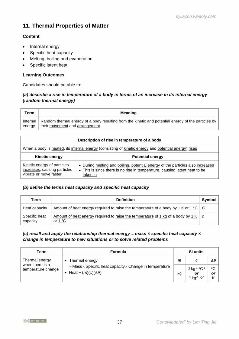
syllacon.weebly.com
37 ‘Consylladated’ by Lim Ting Jie
11. Thermal Properties of Matter
Content
• Internal energy
• Specific heat capacity
• Melting, boiling and evaporation
• Specific latent heat
Learning Outcomes
Candidates should be able to:
(a) describe a rise in temperature of a body in terms of an increase in its internal energy
(random thermal energy)
Term Meaning
Internal energy
Random thermal energy of a body resulting from the kinetic and potential energy of the particles by their movement and arrangement
Description of rise in temperature of a body
When a body is heated, its internal energy (consisting of kinetic energy and potential energy) rises
Kinetic energy Potential energy
Kinetic energy of particles increases, causing particles vibrate or move faster
• During melting and boiling, potential energy of the particles also increases
• This is since there is no rise in temperature, causing latent heat to be taken in
(b) define the terms heat capacity and specific heat capacity
Term Definition Symbol
Heat capacity Amount of heat energy required to raise the temperature of a body by 1 K or 1 °C C
Specific heat capacity
Amount of heat energy required to raise the temperature of 1 kg of a body by 1 K or 1 °C
c
(c) recall and apply the relationship thermal energy = mass × specific heat capacity ×
change in temperature to new situations or to solve related problems
Term Formula SI units
Thermal energy when there is a temperature change
• Thermal energy
Mass Specific heat capacity Change in temperature=
• Heat ( )( )( )m c =
m c
kg J kg-1 oC-1
or J kg-1 K-1
oC or K
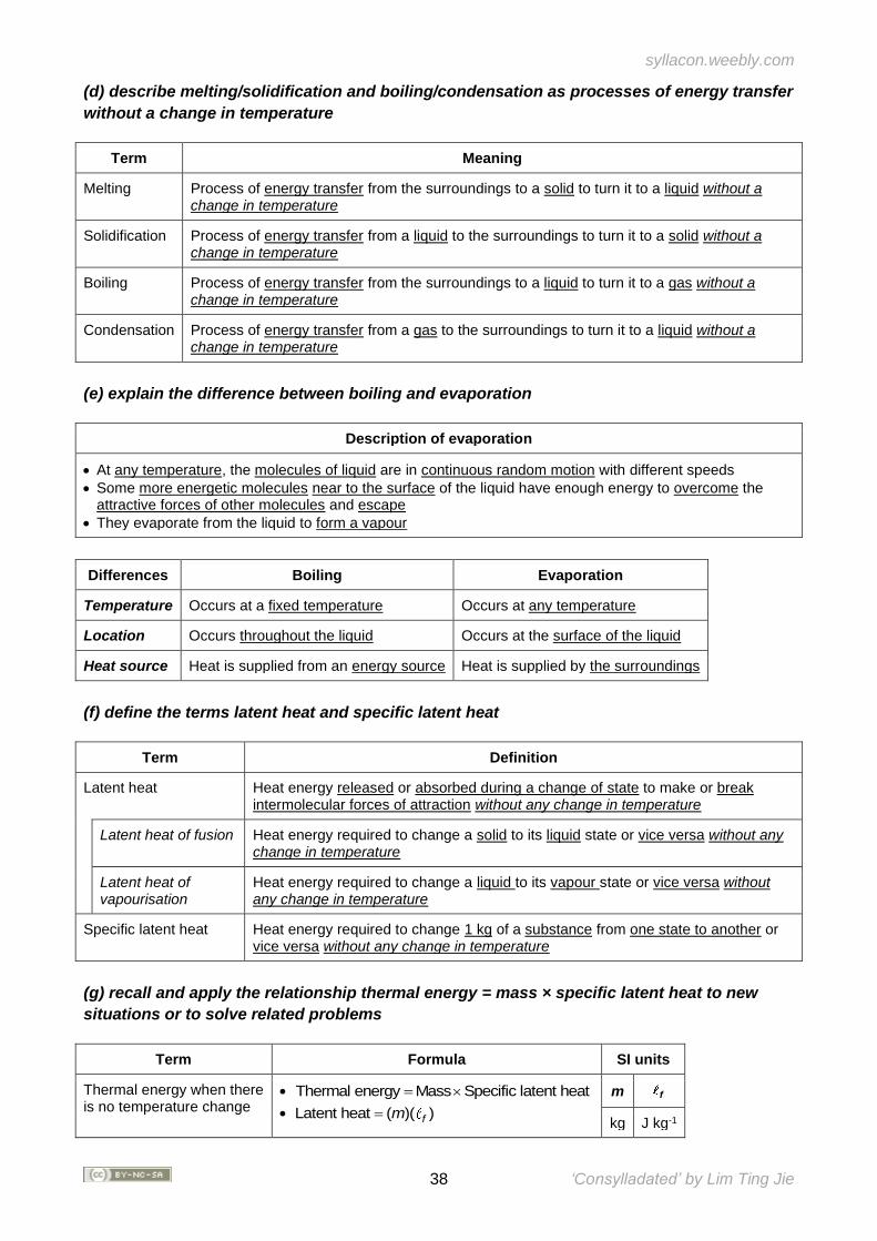
syllacon.weebly.com
38 ‘Consylladated’ by Lim Ting Jie
(d) describe melting/solidification and boiling/condensation as processes of energy transfer
without a change in temperature
Term Meaning
Melting Process of energy transfer from the surroundings to a solid to turn it to a liquid without a change in temperature
Solidification Process of energy transfer from a liquid to the surroundings to turn it to a solid without a change in temperature
Boiling Process of energy transfer from the surroundings to a liquid to turn it to a gas without a change in temperature
Condensation Process of energy transfer from a gas to the surroundings to turn it to a liquid without a change in temperature
(e) explain the difference between boiling and evaporation
Description of evaporation
• At any temperature, the molecules of liquid are in continuous random motion with different speeds
• Some more energetic molecules near to the surface of the liquid have enough energy to overcome the attractive forces of other molecules and escape
• They evaporate from the liquid to form a vapour
Differences Boiling Evaporation
Temperature Occurs at a fixed temperature Occurs at any temperature
Location Occurs throughout the liquid Occurs at the surface of the liquid
Heat source Heat is supplied from an energy source Heat is supplied by the surroundings
(f) define the terms latent heat and specific latent heat
Term Definition
Latent heat Heat energy released or absorbed during a change of state to make or break intermolecular forces of attraction without any change in temperature
Latent heat of fusion Heat energy required to change a solid to its liquid state or vice versa without any change in temperature
Latent heat of vapourisation
Heat energy required to change a liquid to its vapour state or vice versa without any change in temperature
Specific latent heat Heat energy required to change 1 kg of a substance from one state to another or vice versa without any change in temperature
(g) recall and apply the relationship thermal energy = mass × specific latent heat to new
situations or to solve related problems
Term Formula SI units
Thermal energy when there is no temperature change
• Thermal energy Mass Specific latent heat=
• Latent heat ( )( )fm=
m f
kg J kg-1
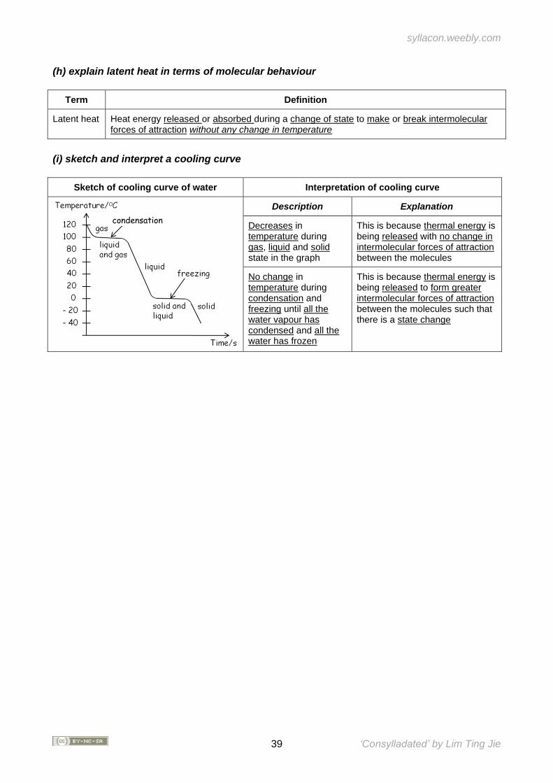
syllacon.weebly.com
39 ‘Consylladated’ by Lim Ting Jie
(h) explain latent heat in terms of molecular behaviour
Term Definition
Latent heat Heat energy released or absorbed during a change of state to make or break intermolecular forces of attraction without any change in temperature
(i) sketch and interpret a cooling curve
Sketch of cooling curve of water Interpretation of cooling curve
Description Explanation
Decreases in temperature during gas, liquid and solid state in the graph
This is because thermal energy is being released with no change in intermolecular forces of attraction between the molecules
No change in temperature during condensation and freezing until all the water vapour has condensed and all the water has frozen
This is because thermal energy is being released to form greater intermolecular forces of attraction between the molecules such that there is a state change
condensation
syllacon.weebly.com
40 ‘Consylladated’ by Lim Ting Jie
SECTION IV: WAVES
Overview Waves are inherent in our everyday lives. Much of our understanding of wave phenomena has been accumulated over the centuries through the study of light (optics) and sound (acoustics). The nature of oscillations in light was only understood when James Clerk Maxwell, in his unification of electricity, magnetism and electromagnetic waves, stated that all electromagnetic fields spread in the form of waves. Using a mathematical model (Maxwell’s equations), he calculated the speed of electromagnetic waves and found it to be close to the speed of light, leading him to make a bold but correct inference that light consists of propagating electromagnetic disturbances. This gave the very nature of electromagnetic waves, and hence its name. In this section, we examine the nature of waves in terms of the coordinated movement of particles. The discussion moves on to wave propagation and its uses by studying the properties of light, electromagnetic waves and sound, as well as their applications in wireless communication, home appliances, medicine and industry.
Extracted from PHYSICS GCE ORDINARY LEVEL (2014) Syllabus Document
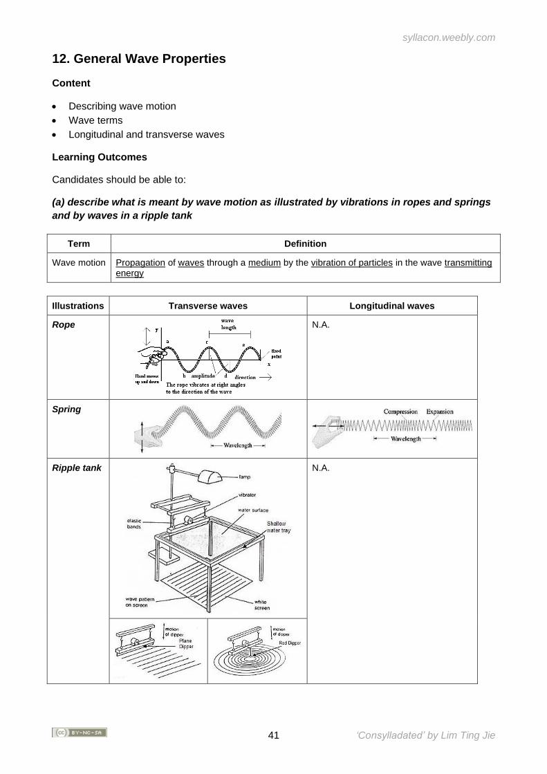
syllacon.weebly.com
41 ‘Consylladated’ by Lim Ting Jie
12. General Wave Properties
Content
• Describing wave motion
• Wave terms
• Longitudinal and transverse waves
Learning Outcomes
Candidates should be able to:
(a) describe what is meant by wave motion as illustrated by vibrations in ropes and springs
and by waves in a ripple tank
Term Definition
Wave motion Propagation of waves through a medium by the vibration of particles in the wave transmitting energy
Illustrations Transverse waves Longitudinal waves
Rope
N.A.
Spring
Ripple tank
N.A.
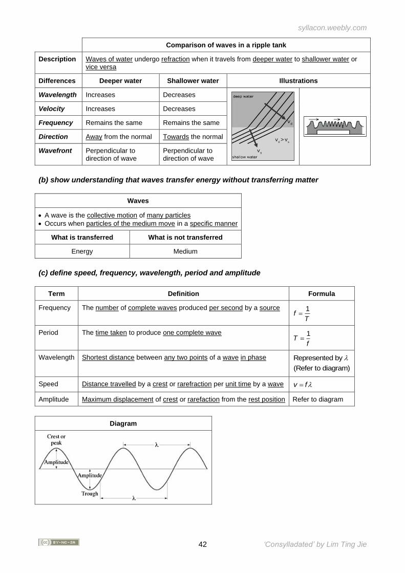
syllacon.weebly.com
42 ‘Consylladated’ by Lim Ting Jie
Comparison of waves in a ripple tank
Description Waves of water undergo refraction when it travels from deeper water to shallower water or vice versa
Differences Deeper water Shallower water Illustrations
Wavelength Increases Decreases
Velocity Increases Decreases
Frequency Remains the same Remains the same
Direction Away from the normal Towards the normal
Wavefront Perpendicular to direction of wave
Perpendicular to direction of wave
(b) show understanding that waves transfer energy without transferring matter
Waves
• A wave is the collective motion of many particles
• Occurs when particles of the medium move in a specific manner
What is transferred What is not transferred
Energy Medium
(c) define speed, frequency, wavelength, period and amplitude
Term Definition Formula
Frequency The number of complete waves produced per second by a source 1f
T=
Period The time taken to produce one complete wave 1T
f=
Wavelength Shortest distance between any two points of a wave in phase Represented by
(Refer to diagram)
Speed Distance travelled by a crest or rarefraction per unit time by a wave v f=
Amplitude Maximum displacement of crest or rarefaction from the rest position Refer to diagram
Diagram
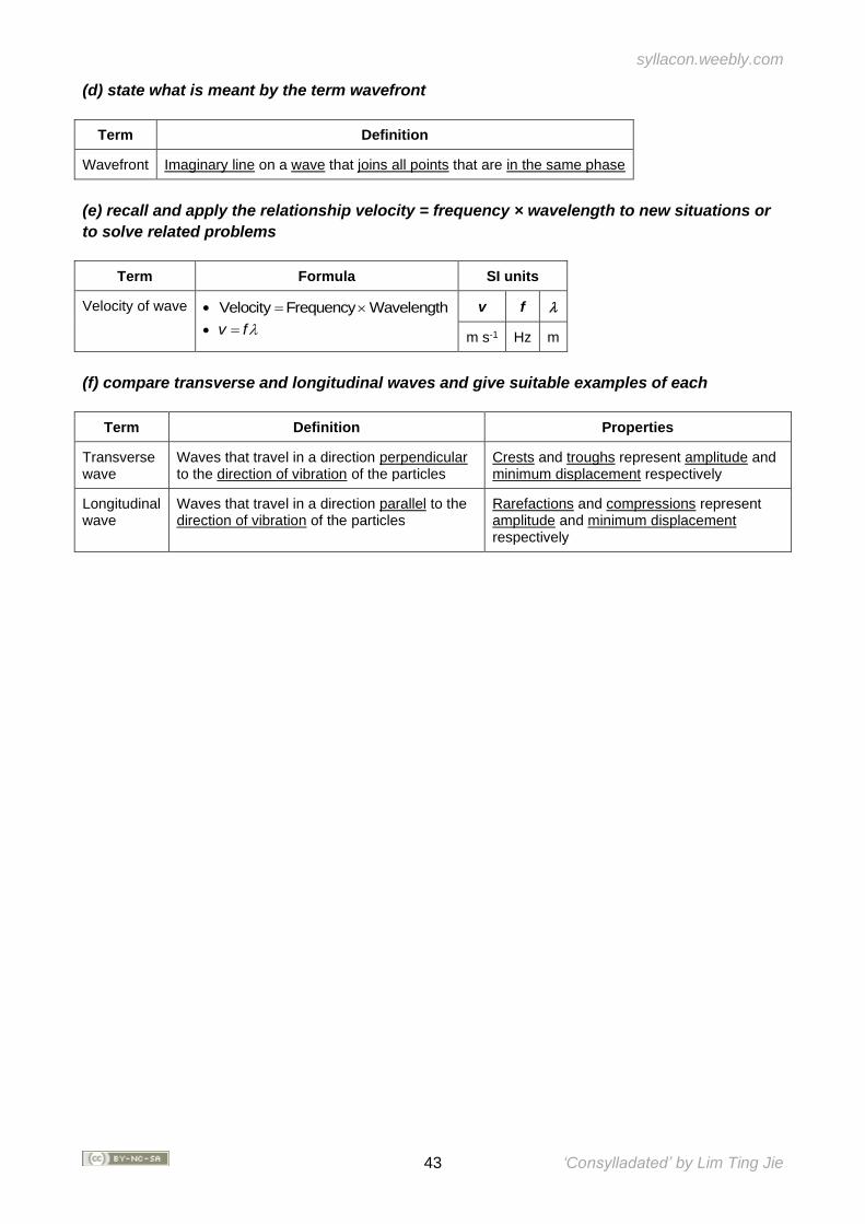
syllacon.weebly.com
43 ‘Consylladated’ by Lim Ting Jie
(d) state what is meant by the term wavefront
Term Definition
Wavefront Imaginary line on a wave that joins all points that are in the same phase
(e) recall and apply the relationship velocity = frequency × wavelength to new situations or
to solve related problems
Term Formula SI units
Velocity of wave • Velocity Frequency Wavelength=
• v f=
v f
m s-1 Hz m
(f) compare transverse and longitudinal waves and give suitable examples of each
Term Definition Properties
Transverse wave
Waves that travel in a direction perpendicular to the direction of vibration of the particles
Crests and troughs represent amplitude and minimum displacement respectively
Longitudinal wave
Waves that travel in a direction parallel to the direction of vibration of the particles
Rarefactions and compressions represent amplitude and minimum displacement respectively
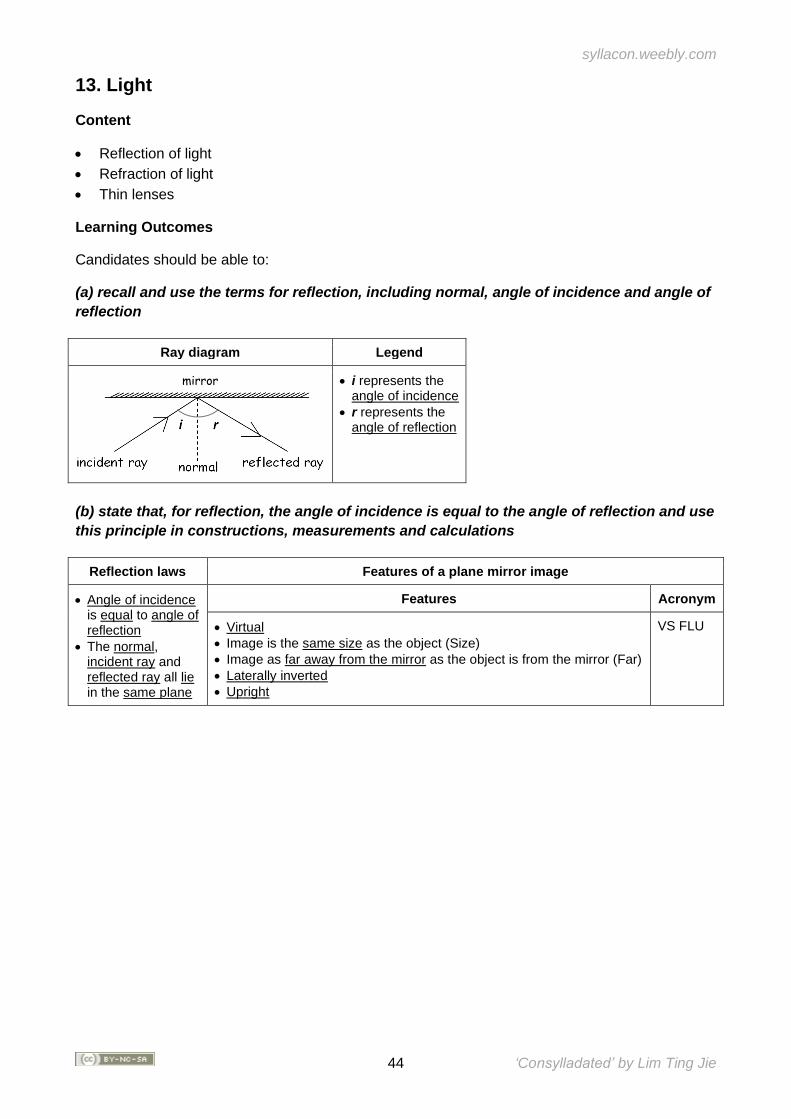
syllacon.weebly.com
44 ‘Consylladated’ by Lim Ting Jie
13. Light
Content
• Reflection of light
• Refraction of light
• Thin lenses
Learning Outcomes
Candidates should be able to:
(a) recall and use the terms for reflection, including normal, angle of incidence and angle of
reflection
Ray diagram Legend
mirror
• i represents the angle of incidence
• r represents the angle of reflection
(b) state that, for reflection, the angle of incidence is equal to the angle of reflection and use
this principle in constructions, measurements and calculations
Reflection laws Features of a plane mirror image
• Angle of incidence is equal to angle of reflection
• The normal, incident ray and reflected ray all lie in the same plane
Features Acronym
• Virtual
• Image is the same size as the object (Size)
• Image as far away from the mirror as the object is from the mirror (Far)
• Laterally inverted
• Upright
VS FLU
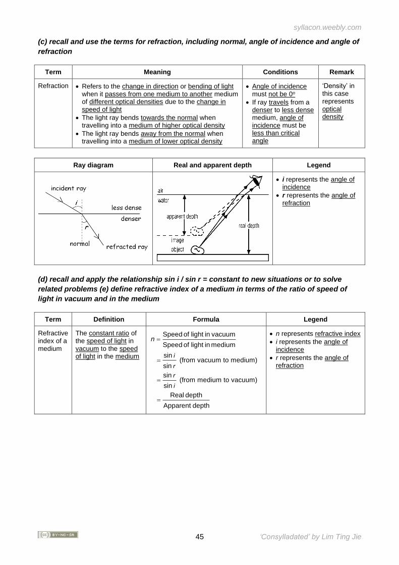
syllacon.weebly.com
45 ‘Consylladated’ by Lim Ting Jie
(c) recall and use the terms for refraction, including normal, angle of incidence and angle of
refraction
Term Meaning Conditions Remark
Refraction • Refers to the change in direction or bending of light when it passes from one medium to another medium of different optical densities due to the change in speed of light
• The light ray bends towards the normal when travelling into a medium of higher optical density
• The light ray bends away from the normal when travelling into a medium of lower optical density
• Angle of incidence must not be 0o
• If ray travels from a denser to less dense medium, angle of incidence must be less than critical angle
‘Density’ in this case represents optical density
Ray diagram Real and apparent depth Legend
• i represents the angle of incidence
• r represents the angle of refraction
(d) recall and apply the relationship sin i / sin r = constant to new situations or to solve
related problems (e) define refractive index of a medium in terms of the ratio of speed of
light in vacuum and in the medium
Term Definition Formula Legend
Refractive index of a medium
The constant ratio of the speed of light in vacuum to the speed of light in the medium
Speed of light in vacuum
Speed of light in mediumn =
sin (from vacuum to medium)
sin =
i
r sin
(from medium to vacuum)sin
=r
i
Real depth
Apparent depth=
• n represents refractive index
• i represents the angle of incidence
• r represents the angle of refraction
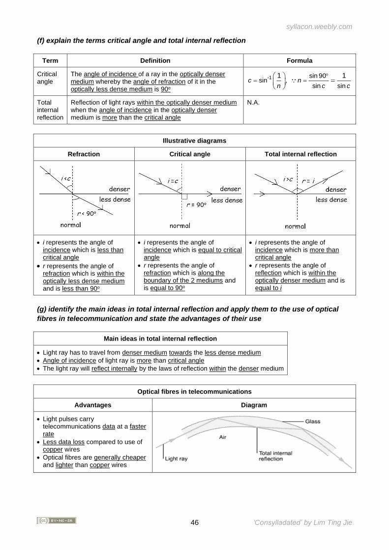
syllacon.weebly.com
46 ‘Consylladated’ by Lim Ting Jie
(f) explain the terms critical angle and total internal reflection
Term Definition Formula
Critical angle
The angle of incidence of a ray in the optically denser medium whereby the angle of refraction of it in the optically less dense medium is 90o
-1 sin 90sin ,
sin sin
1 1c n
n c c
= =
=
Total internal reflection
Reflection of light rays within the optically denser medium when the angle of incidence in the optically denser medium is more than the critical angle
N.A.
Illustrative diagrams
Refraction Critical angle Total internal reflection
• i represents the angle of incidence which is less than critical angle
• r represents the angle of refraction which is within the optically less dense medium and is less than 90o
• i represents the angle of incidence which is equal to critical angle
• r represents the angle of refraction which is along the boundary of the 2 mediums and is equal to 90o
• i represents the angle of incidence which is more than critical angle
• r represents the angle of reflection which is within the optically denser medium and is equal to i
(g) identify the main ideas in total internal reflection and apply them to the use of optical
fibres in telecommunication and state the advantages of their use
Main ideas in total internal reflection
• Light ray has to travel from denser medium towards the less dense medium
• Angle of incidence of light ray is more than critical angle
• The light ray will reflect internally by the laws of reflection within the denser medium
Optical fibres in telecommunications
Advantages Diagram
• Light pulses carry telecommunications data at a faster rate
• Less data loss compared to use of copper wires
• Optical fibres are generally cheaper and lighter than copper wires
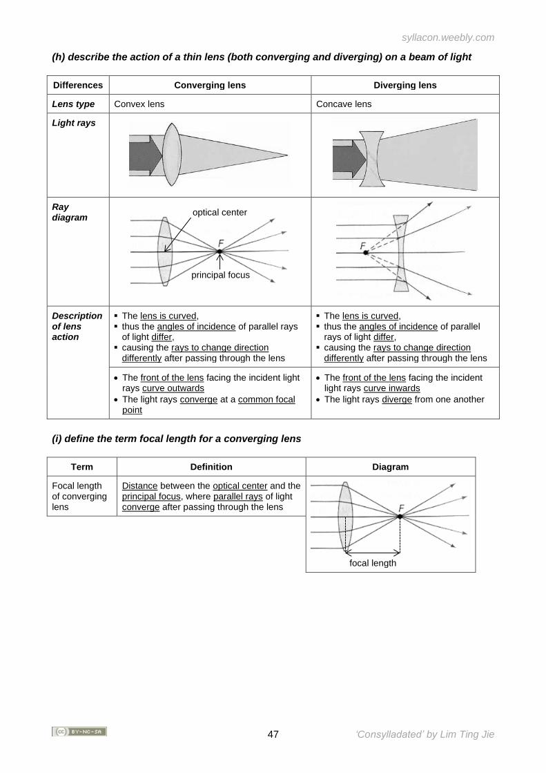
syllacon.weebly.com
47 ‘Consylladated’ by Lim Ting Jie
(h) describe the action of a thin lens (both converging and diverging) on a beam of light
Differences Converging lens Diverging lens
Lens type Convex lens Concave lens
Light rays
Ray diagram
Description of lens action
▪ The lens is curved, ▪ thus the angles of incidence of parallel rays
of light differ, ▪ causing the rays to change direction
differently after passing through the lens
▪ The lens is curved, ▪ thus the angles of incidence of parallel
rays of light differ, ▪ causing the rays to change direction
differently after passing through the lens
• The front of the lens facing the incident light rays curve outwards
• The light rays converge at a common focal point
• The front of the lens facing the incident light rays curve inwards
• The light rays diverge from one another
(i) define the term focal length for a converging lens
Term Definition Diagram
Focal length of converging lens
Distance between the optical center and the principal focus, where parallel rays of light converge after passing through the lens
focal length
optical center
principal focus
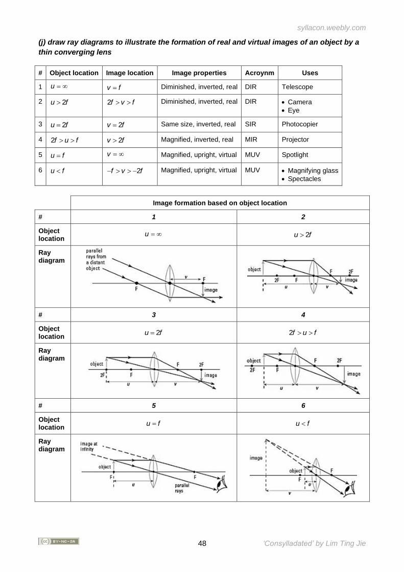
syllacon.weebly.com
48 ‘Consylladated’ by Lim Ting Jie
(j) draw ray diagrams to illustrate the formation of real and virtual images of an object by a
thin converging lens
# Object location Image location Image properties Acroynm Uses
1 u = v f= Diminished, inverted, real DIR Telescope
2 2u f 2f v f Diminished, inverted, real DIR • Camera
• Eye
3 2u f= 2v f= Same size, inverted, real SIR Photocopier
4 2f u f 2v f Magnified, inverted, real MIR Projector
5 u f= v = Magnified, upright, virtual MUV Spotlight
6 u f 2f v f− − Magnified, upright, virtual MUV • Magnifying glass
• Spectacles
Image formation based on object location
# 1 2
Object location
u = 2u f
Ray diagram
# 3 4
Object location
2u f= 2f u f
Ray diagram
# 5 6
Object location
u f= u f
Ray diagram
syllacon.weebly.com
49 ‘Consylladated’ by Lim Ting Jie
14. Electromagnetic Spectrum
Content
• Properties of electromagnetic waves
• Applications of electromagnetic waves
• Effects of electromagnetic waves on cells and tissue
Learning Outcomes
Candidates should be able to:
(a) state that all electromagnetic waves are transverse waves that travel with the same
speed in vacuum and state the magnitude of this speed
# Point Property of electromagnetic waves (EM waves)
1 Type • Transverse waves
• Electric and magnetic fields oscillate 90o to each other
2 Laws They obey the laws of reflection and refraction
3 Electric charge No electric charge is carried through EM waves
4 Medium No medium is required and the wave can travel through vacuum
5 Frequency Remains the same all the time
6 Wavelength Decreases from optically less dense to denser medium
7 Velocity • 3 x 10⁸ ms-1 in vacuum, slows down in matter
• Decreases from optically less dense to denser medium
syllacon.weebly.com
50 ‘Consylladated’ by Lim Ting Jie
(b) describe the main components of the electromagnetic spectrum (c) state examples of
the use of the following components: (i) radiowaves (e.g. radio and television
communication) (ii) microwaves (e.g. microwave oven and satellite television) (iii) infra-red
(e.g. infra-red remote controllers and intruder alarms) (iv) light (e.g. optical fibres for
medical uses and telecommunications) (v) ultra-violet (e.g. sunbeds and sterilisation) (vi) X-
rays (e.g. radiological and engineering applications) (vii) gamma rays (e.g. medical
treatment)
Component Frequency Applications Description
Radio waves 1× 10^ 8 Hz Radio and television communications
Able to go around obstructions (due to longer wavelengths)
Microwaves 1× 10^ 10 Hz Microwave oven Water molecules vibrate millions of times a second to produce heat from friction
Satellite television Can penetrate haze, light rain, snow, clouds and smoke with proper alignment
Infra-red 1× 10^ 12 Hz Remote controllers −
Intruder alarms Alarm rings when it receives infra-red radiation an intruding human gives out
Light (Red) 5× 10^ 14 Hz Medical optical fibres −
(Violet) Telecommunications −
Ultra-violet 3× 10^ 16 Hz Sunbeds Artificial tanning (shorter frequency UVA)
Sterilisation Germicidal lamps (longer frequency UVB/C)
X-rays 3× 10^ 18 Hz • Diagnose fractures
• Airport scanners
Can penetrate through all materials other than lead, thus may be applied using X-ray imagery
Gamma rays 3× 10^ 20 Hz Cancer treatment Kill cancer cells in cancerous tumours (high energy waves)
Changes in the EM spectrum from radio to gamma waves
Frequency Wavelength
Increases from radio waves to gamma rays Decreases from radio waves to gamma rays
(d) describe the effects of absorbing electromagnetic waves, e.g. heating, ionisation and
damage to living cells and tissue
Effects of absorbing electromagnetic waves
Infrared High energy EM waves X-rays
• Human skin absorbs infrared waves from BBQ pits
• Human bodies will receive the radiation and be heated to feel warm
• EM waves of frequencies higher than light have high energy causing ionisation
• Ionisation of living matter in human bodies damages chromosomes, living cells and tissues
• Overexposure leads to premature ageing and lifespan shortening
• Overexposure of developing fetus to X-ray imagery can cause abnormal cell division
• A deformed baby and leukemia may result
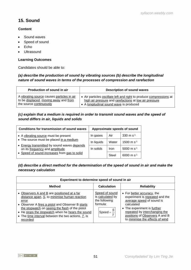
syllacon.weebly.com
51 ‘Consylladated’ by Lim Ting Jie
15. Sound
Content
• Sound waves
• Speed of sound
• Echo
• Ultrasound
Learning Outcomes
Candidates should be able to:
(a) describe the production of sound by vibrating sources (b) describe the longitudinal
nature of sound waves in terms of the processes of compression and rarefaction
Production of sound in air Description of sound waves
A vibrating source causes particles in air to be displaced, moving away and from the source continuously
• Air particles oscillate left and right to produce compressions at high air pressure and rarefactions at low air pressure
• A longitudinal sound wave is produced
(c) explain that a medium is required in order to transmit sound waves and the speed of
sound differs in air, liquids and solids
Conditions for transmission of sound waves Approximate speeds of sound
• A vibrating source must be present
• The source must be placed in a medium
• Energy transmitted by sound waves depends on its frequency and amplitude
• Speed of sound increases from gas to solid
In gases Air 330 m s-1
In liquids Water 1500 m s-1
In solids Iron 5000 m s-1
Steel 6000 m s-1
(d) describe a direct method for the determination of the speed of sound in air and make the
necessary calculation
Experiment to determine speed of sound in air
Method Calculation Reliability
• Observers A and B are positioned at a far distance apart, S, to minimise human reaction error
• Observer A fires a pistol and Observer B starts the stopwatch on seeing the flash of the pistol
• He stops the stopwatch when he hears the sound
• The time interval between the two actions, T, is recorded
Speed of sound is calculated by the following formula:
SpeedS
T=
• For better accuracy, the experiment is repeated and the average speed of sound is calculated
• The experiment is further repeated by interchanging the positions of Observers A and B to minimise the effects of wind
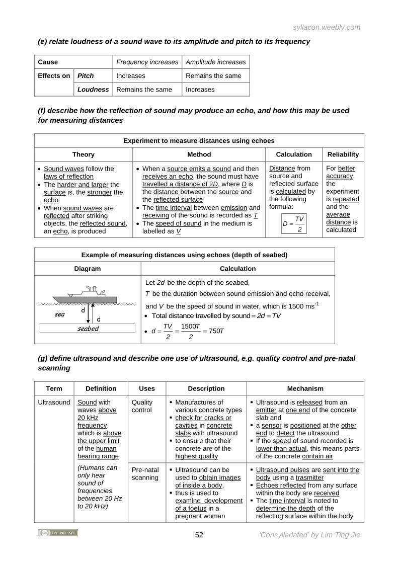
syllacon.weebly.com
52 ‘Consylladated’ by Lim Ting Jie
(e) relate loudness of a sound wave to its amplitude and pitch to its frequency
Cause Frequency increases Amplitude increases
Effects on Pitch Increases Remains the same
Loudness Remains the same Increases
(f) describe how the reflection of sound may produce an echo, and how this may be used
for measuring distances
Experiment to measure distances using echoes
Theory Method Calculation Reliability
• Sound waves follow the laws of reflectlon
• The harder and larger the surface is, the stronger the echo
• When sound waves are reflected after striking objects, the reflected sound, an echo, is produced
• When a source emits a sound and then receives an echo, the sound must have travelled a distance of 2D, where D is the distance between the source and the reflected surface
• The time interval between emission and receiving of the sound is recorded as T
• The speed of sound in the medium is labelled as V
Distance from source and reflected surface is calculated by the following formula:
TVD
2=
For better accuracy, the experiment is repeated and the average distance is calculated
Example of measuring distances using echoes (depth of seabed)
Diagram Calculation
-1
Let be the depth of the seabed,
be the duration between sound emission and echo receival,
and be the speed of sound in water, which is 1500 ms
2d
T
V
• Total distance travelled by sound 2d TV= =
• 1500
750TV T
d T2 2
= = =
(g) define ultrasound and describe one use of ultrasound, e.g. quality control and pre-natal
scanning
Term Definition Uses Description Mechanism
Ultrasound Sound with waves above 20 kHz frequency, which is above the upper limit of the human hearing range
(Humans can only hear sound of frequencies between 20 Hz to 20 kHz)
Quality control
▪ Manufactures of various concrete types
▪ check for cracks or cavities in concrete slabs with ultrasound
▪ to ensure that their concrete are of the highest quality
▪ Ultrasound is released from an emitter at one end of the concrete slab and
▪ a sensor is positioned at the other end to detect the ultrasound
▪ If the speed of sound recorded is lower than actual, this means parts of the concrete contain air
Pre-natal scanning
▪ Ultrasound can be used to obtain images of inside a body,
▪ thus is used to examine development of a foetus in a pregnant woman
▪ Ultrasound pulses are sent into the body using a trasmitter
▪ Echoes reflected from any surface within the body are received
▪ The time interval is noted to determine the depth of the reflecting surface within the body
syllacon.weebly.com
53 ‘Consylladated’ by Lim Ting Jie
SECTION V: ELECTRICITY AND MAGNETISM
Overview For a long time, electricity and magnetism were seen as independent phenomena. Hans Christian Oersted, in 1802, discovered that a current carrying conductor deflected a compass needle. This discovery was overlooked by the scientific community until 18 years later. It may be a chance discovery, but it takes an observant scientist to notice. The exact relationship between an electric current and the magnetic field it produced was deduced mainly through the work of Andre Marie Ampere. However, the major discoveries in electromagnetism were made by two of the greatest names in physics, Michael Faraday and James Clerk Maxwell. The section begins with a discussion of electric charges that are static, i.e. not moving. Next, we study the phenomena associated with moving charges and the concepts of current, voltage and resistance. We also study how these concepts are applied to simple circuits and household electricity. Thereafter, we study the interaction of magnetic fields to pave the way for the study of the interrelationship between electricity and magnetism. The phenomenon in which a current interacts with a magnetic field is studied in electromagnetism, while the phenomenon in which a current or electromotive force is induced in a moving conductor within a magnetic field is studied in electromagnetic induction.
Extracted from CHEMISTRY GCE ORDINARY LEVEL (2014) Syllabus Document
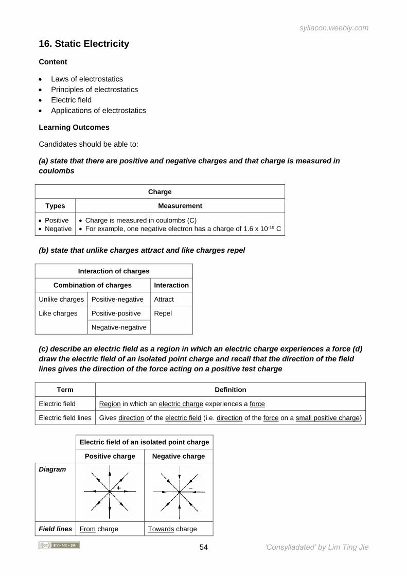
syllacon.weebly.com
54 ‘Consylladated’ by Lim Ting Jie
16. Static Electricity
Content
• Laws of electrostatics
• Principles of electrostatics
• Electric field
• Applications of electrostatics
Learning Outcomes
Candidates should be able to:
(a) state that there are positive and negative charges and that charge is measured in
coulombs
Charge
Types Measurement
• Positive
• Negative
• Charge is measured in coulombs (C)
• For example, one negative electron has a charge of 1.6 x 10⁻¹⁹ C
(b) state that unlike charges attract and like charges repel
Interaction of charges
Combination of charges Interaction
Unlike charges Positive-negative Attract
Like charges Positive-positive Repel
Negative-negative
(c) describe an electric field as a region in which an electric charge experiences a force (d)
draw the electric field of an isolated point charge and recall that the direction of the field
lines gives the direction of the force acting on a positive test charge
Term Definition
Electric field Region in which an electric charge experiences a force
Electric field lines Gives direction of the electric field (i.e. direction of the force on a small positive charge)
Electric field of an isolated point charge
Positive charge Negative charge
Diagram
Field lines From charge Towards charge
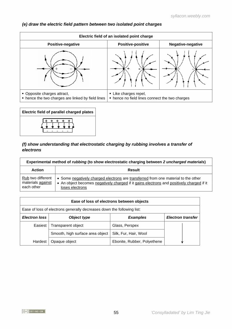
syllacon.weebly.com
55 ‘Consylladated’ by Lim Ting Jie
(e) draw the electric field pattern between two isolated point charges
Electric field of an isolated point charge
Positive-negative Positive-positive Negative-negative
▪ Opposite charges attract, ▪ hence the two charges are linked by field lines
▪ Like charges repel, ▪ hence no field lines connect the two charges
Electric field of parallel charged plates
(f) show understanding that electrostatic charging by rubbing involves a transfer of
electrons
Experimental method of rubbing (to show electrostatic charging between 2 uncharged materials)
Action Result
Rub two different materials against each other
• Some negatively charged electrons are transferred from one material to the other
• An object becomes negatively charged if it gains electrons and positively charged if it loses electrons
Ease of loss of electrons between objects
Ease of loss of electrons generally decreases down the following list:
Electron loss Object type Examples Electron transfer
Easiest Transparent object Glass, Perspex
Smooth, high surface area object Silk, Fur, Hair, Wool
Hardest Opaque object Ebonite, Rubber, Polyethene
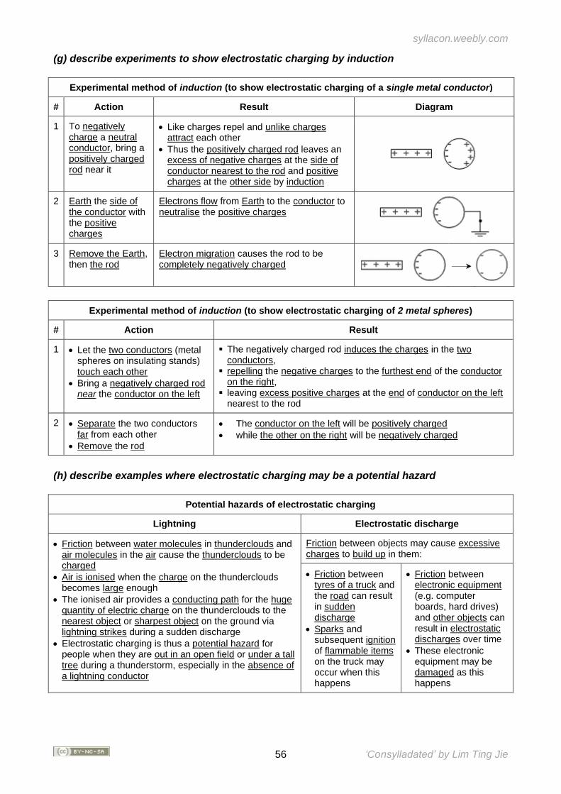
syllacon.weebly.com
56 ‘Consylladated’ by Lim Ting Jie
(g) describe experiments to show electrostatic charging by induction
Experimental method of induction (to show electrostatic charging of a single metal conductor)
# Action Result Diagram
1 To negatively charge a neutral conductor, bring a positively charged rod near it
• Like charges repel and unlike charges attract each other
• Thus the positively charged rod leaves an excess of negative charges at the side of conductor nearest to the rod and positive charges at the other side by induction
2 Earth the side of the conductor with the positive charges
Electrons flow from Earth to the conductor to neutralise the positive charges
3 Remove the Earth, then the rod
Electron migration causes the rod to be completely negatively charged
Experimental method of induction (to show electrostatic charging of 2 metal spheres)
# Action Result
1 • Let the two conductors (metal spheres on insulating stands) touch each other
• Bring a negatively charged rod near the conductor on the left
▪ The negatively charged rod induces the charges in the two conductors,
▪ repelling the negative charges to the furthest end of the conductor on the right,
▪ leaving excess positive charges at the end of conductor on the left nearest to the rod
2 • Separate the two conductors far from each other
• Remove the rod
• The conductor on the left will be positively charged
• while the other on the right will be negatively charged
(h) describe examples where electrostatic charging may be a potential hazard
Potential hazards of electrostatic charging
Lightning Electrostatic discharge
• Friction between water molecules in thunderclouds and air molecules in the air cause the thunderclouds to be charged
• Air is ionised when the charge on the thunderclouds becomes large enough
• The ionised air provides a conducting path for the huge quantity of electric charge on the thunderclouds to the nearest object or sharpest object on the ground via lightning strikes during a sudden discharge
• Electrostatic charging is thus a potential hazard for people when they are out in an open field or under a tall tree during a thunderstorm, especially in the absence of a lightning conductor
Friction between objects may cause excessive charges to build up in them:
• Friction between tyres of a truck and the road can result in sudden discharge
• Sparks and subsequent ignition of flammable items on the truck may occur when this happens
• Friction between electronic equipment (e.g. computer boards, hard drives) and other objects can result in electrostatic discharges over time
• These electronic equipment may be damaged as this happens
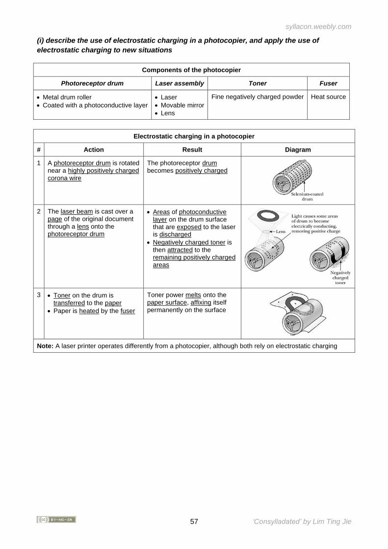
syllacon.weebly.com
57 ‘Consylladated’ by Lim Ting Jie
(i) describe the use of electrostatic charging in a photocopier, and apply the use of
electrostatic charging to new situations
Components of the photocopier
Photoreceptor drum Laser assembly Toner Fuser
• Metal drum roller
• Coated with a photoconductive layer
• Laser
• Movable mirror
• Lens
Fine negatively charged powder Heat source
Electrostatic charging in a photocopier
# Action Result Diagram
1 A photoreceptor drum is rotated near a highly positively charged corona wire
The photoreceptor drum becomes positively charged
2 The laser beam is cast over a page of the original document through a lens onto the photoreceptor drum
• Areas of photoconductive layer on the drum surface that are exposed to the laser is discharged
• Negatively charged toner is then attracted to the remaining positively charged areas
3 • Toner on the drum is transferred to the paper
• Paper is heated by the fuser
Toner power melts onto the paper surface, affixing itself permanently on the surface
Note: A laser printer operates differently from a photocopier, although both rely on electrostatic charging
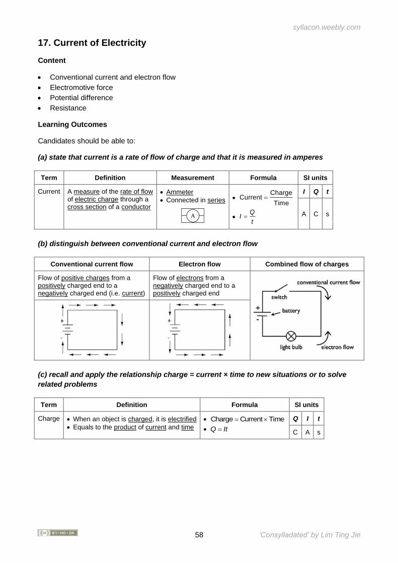
syllacon.weebly.com
58 ‘Consylladated’ by Lim Ting Jie
17. Current of Electricity
Content
• Conventional current and electron flow
• Electromotive force
• Potential difference
• Resistance
Learning Outcomes
Candidates should be able to:
(a) state that current is a rate of flow of charge and that it is measured in amperes
Term Definition Measurement Formula SI units
Current A measure of the rate of flow of electric charge through a cross section of a conductor
• Ammeter
• Connected in series
• Charge
CurrentTime
=
• Q
It
=
I Q t
A C s
(b) distinguish between conventional current and electron flow
Conventional current flow Electron flow Combined flow of charges
Flow of positive charges from a positively charged end to a negatively charged end (i.e. current)
Flow of electrons from a negatively charged end to a positively charged end
(c) recall and apply the relationship charge = current × time to new situations or to solve
related problems
Term Definition Formula SI units
Charge • When an object is charged, it is electrified
• Equals to the product of current and time
• Charge Current Time=
• Q It=
Q I t
C A s
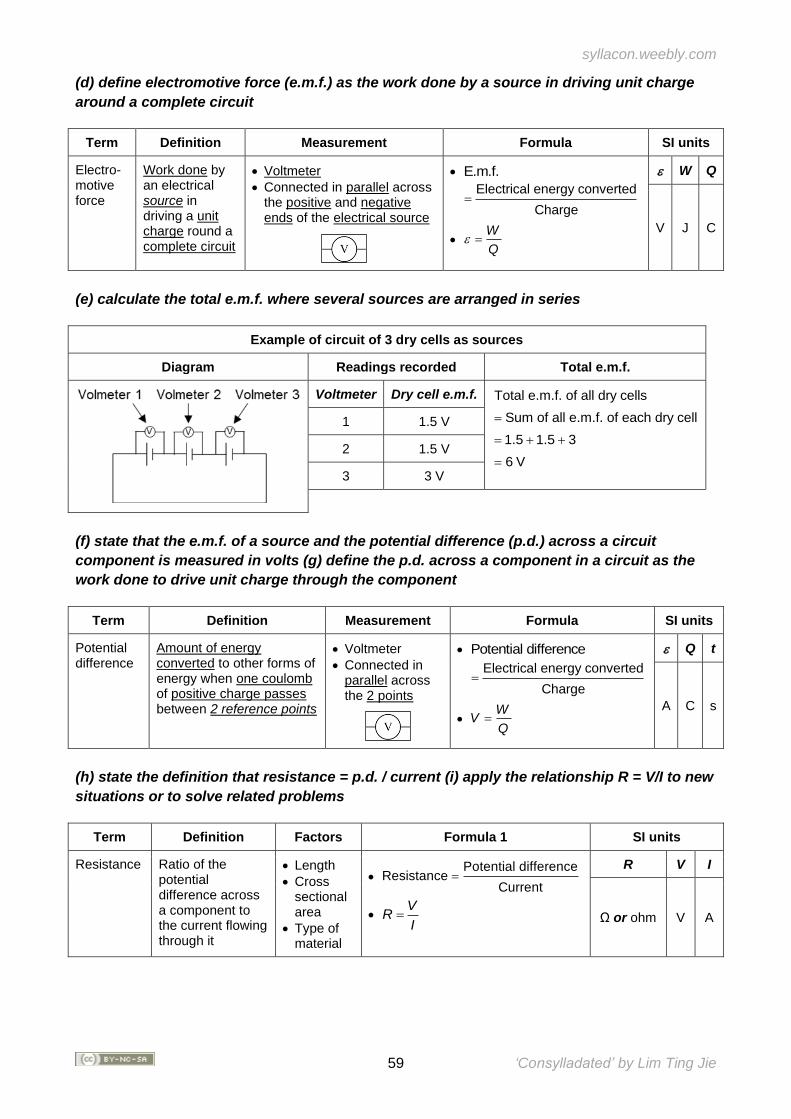
syllacon.weebly.com
59 ‘Consylladated’ by Lim Ting Jie
(d) define electromotive force (e.m.f.) as the work done by a source in driving unit charge
around a complete circuit
Term Definition Measurement Formula SI units
Electro-motive force
Work done by an electrical source in driving a unit charge round a complete circuit
• Voltmeter
• Connected in parallel across the positive and negative ends of the electrical source
• E.m.f.
Electrical energy converted
Charge=
• W
Q =
W Q
V J C
(e) calculate the total e.m.f. where several sources are arranged in series
Example of circuit of 3 dry cells as sources
Diagram Readings recorded Total e.m.f.
Voltmeter Dry cell e.m.f. Total e.m.f. of all dry cells
Sum of all e.m.f. of each dry cell
1.5 1.5 3
6 V
=
= + +
=
1 1.5 V
2 1.5 V
3 3 V
(f) state that the e.m.f. of a source and the potential difference (p.d.) across a circuit
component is measured in volts (g) define the p.d. across a component in a circuit as the
work done to drive unit charge through the component
(h) state the definition that resistance = p.d. / current (i) apply the relationship R = V/I to new
situations or to solve related problems
Term Definition Factors Formula 1 SI units
Resistance Ratio of the potential difference across a component to the current flowing through it
• Length
• Cross sectional area
• Type of material
• Potential difference
ResistanceCurrent
=
• V
RI
=
R V I
Ω or ohm V A
Term Definition Measurement Formula SI units
Potential difference
Amount of energy converted to other forms of energy when one coulomb of positive charge passes between 2 reference points
• Voltmeter
• Connected in parallel across the 2 points
• Potential difference
Electrical energy converted
Charge=
• W
VQ
=
Q t
A C s
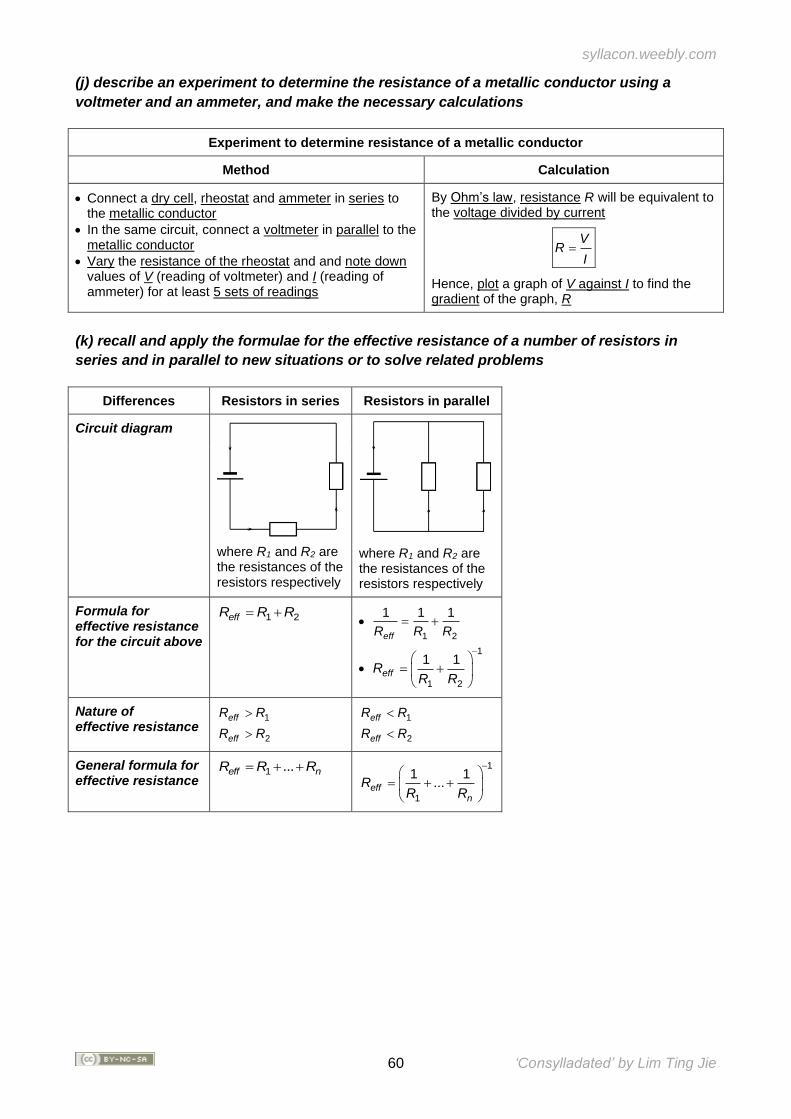
syllacon.weebly.com
60 ‘Consylladated’ by Lim Ting Jie
(j) describe an experiment to determine the resistance of a metallic conductor using a
voltmeter and an ammeter, and make the necessary calculations
Experiment to determine resistance of a metallic conductor
Method Calculation
• Connect a dry cell, rheostat and ammeter in series to the metallic conductor
• In the same circuit, connect a voltmeter in parallel to the metallic conductor
• Vary the resistance of the rheostat and and note down values of V (reading of voltmeter) and I (reading of ammeter) for at least 5 sets of readings
By Ohm’s law, resistance R will be equivalent to the voltage divided by current
VR
I=
Hence, plot a graph of V against I to find the gradient of the graph, R
(k) recall and apply the formulae for the effective resistance of a number of resistors in
series and in parallel to new situations or to solve related problems
Differences Resistors in series Resistors in parallel
Circuit diagram
where R1 and R2 are the resistances of the resistors respectively
where R1 and R2 are the resistances of the resistors respectively
Formula for effective resistance for the circuit above
1 2effR R R= + • 1 2
1 1 1
effR R R= +
•
1
1 2
1 1effR
R R
−
= +
Nature of effective resistance
1
2
eff
eff
R R
R R
1
2
eff
eff
R R
R R
General formula for effective resistance
1 ...eff nR R R= + + 1
1
1 1...eff
n
RR R
−
= + +
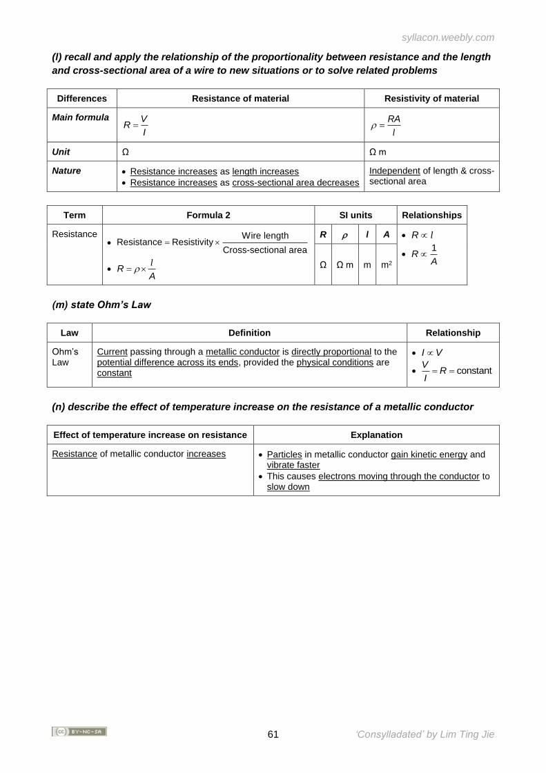
syllacon.weebly.com
61 ‘Consylladated’ by Lim Ting Jie
(l) recall and apply the relationship of the proportionality between resistance and the length
and cross-sectional area of a wire to new situations or to solve related problems
Differences Resistance of material Resistivity of material
Main formula VR
I=
RA =
l
Unit Ω
Ω m
Nature • Resistance increases as length increases
• Resistance increases as cross-sectional area decreases
Independent of length & cross-sectional area
Term Formula 2 SI units Relationships
Resistance •
Wire lengthResistance Resistivity
Cross-sectional area=
• RA
= l
R l A • R l
• 1
RA
Ω Ω m m m2
(m) state Ohm’s Law
Law Definition Relationship
Ohm’s Law
Current passing through a metallic conductor is directly proportional to the potential difference across its ends, provided the physical conditions are constant
• I V
• constantV
RI= =
(n) describe the effect of temperature increase on the resistance of a metallic conductor
Effect of temperature increase on resistance Explanation
Resistance of metallic conductor increases • Particles in metallic conductor gain kinetic energy and vibrate faster
• This causes electrons moving through the conductor to slow down
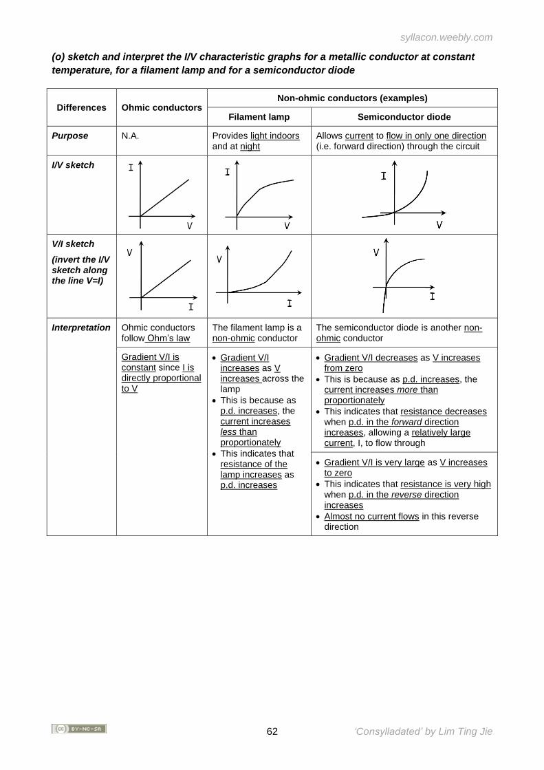
syllacon.weebly.com
62 ‘Consylladated’ by Lim Ting Jie
(o) sketch and interpret the I/V characteristic graphs for a metallic conductor at constant
temperature, for a filament lamp and for a semiconductor diode
Differences Ohmic conductors Non-ohmic conductors (examples)
Filament lamp Semiconductor diode
Purpose N.A. Provides light indoors and at night
Allows current to flow in only one direction (i.e. forward direction) through the circuit
I/V sketch
V/I sketch
(invert the I/V sketch along the line V=I)
Interpretation Ohmic conductors follow Ohm’s law
The filament lamp is a non-ohmic conductor
The semiconductor diode is another non-ohmic conductor
Gradient V/I is constant since I is directly proportional to V
• Gradient V/I increases as V increases across the lamp
• This is because as p.d. increases, the current increases less than proportionately
• This indicates that resistance of the lamp increases as p.d. increases
• Gradient V/I decreases as V increases from zero
• This is because as p.d. increases, the current increases more than proportionately
• This indicates that resistance decreases when p.d. in the forward direction increases, allowing a relatively large current, I, to flow through
• Gradient V/I is very large as V increases to zero
• This indicates that resistance is very high when p.d. in the reverse direction increases
• Almost no current flows in this reverse direction
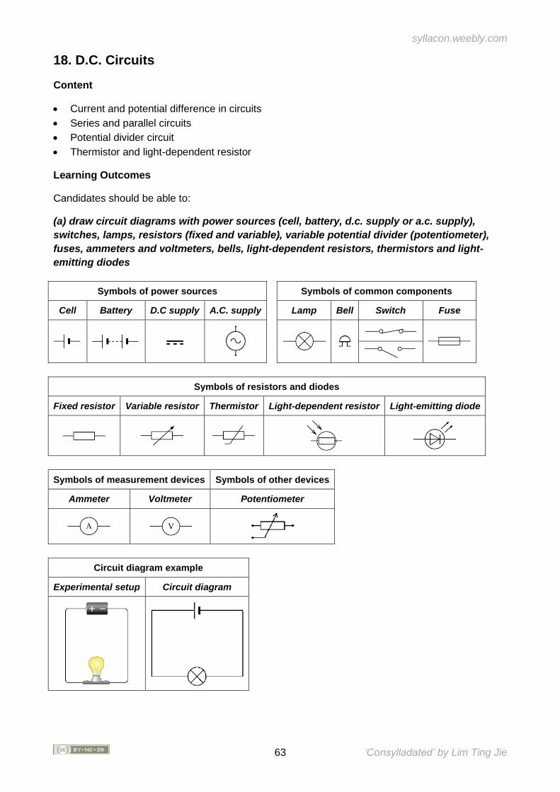
syllacon.weebly.com
63 ‘Consylladated’ by Lim Ting Jie
18. D.C. Circuits
Content
• Current and potential difference in circuits
• Series and parallel circuits
• Potential divider circuit
• Thermistor and light-dependent resistor
Learning Outcomes
Candidates should be able to:
(a) draw circuit diagrams with power sources (cell, battery, d.c. supply or a.c. supply),
switches, lamps, resistors (fixed and variable), variable potential divider (potentiometer),
fuses, ammeters and voltmeters, bells, light-dependent resistors, thermistors and light-
emitting diodes
Symbols of power sources Symbols of common components
Cell Battery D.C supply A.C. supply Lamp Bell Switch Fuse
Symbols of resistors and diodes
Fixed resistor Variable resistor Thermistor Light-dependent resistor Light-emitting diode
Symbols of measurement devices Symbols of other devices
Ammeter Voltmeter Potentiometer
Circuit diagram example
Experimental setup Circuit diagram
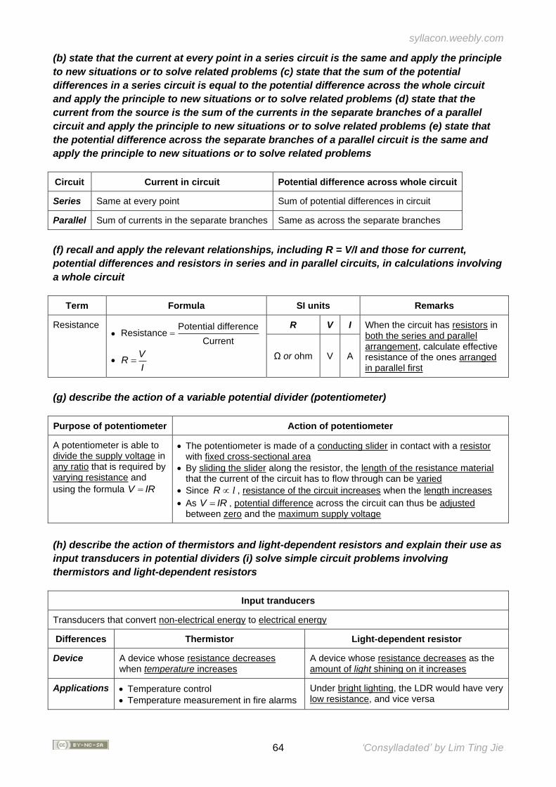
syllacon.weebly.com
64 ‘Consylladated’ by Lim Ting Jie
(b) state that the current at every point in a series circuit is the same and apply the principle
to new situations or to solve related problems (c) state that the sum of the potential
differences in a series circuit is equal to the potential difference across the whole circuit
and apply the principle to new situations or to solve related problems (d) state that the
current from the source is the sum of the currents in the separate branches of a parallel
circuit and apply the principle to new situations or to solve related problems (e) state that
the potential difference across the separate branches of a parallel circuit is the same and
apply the principle to new situations or to solve related problems
Circuit Current in circuit Potential difference across whole circuit
Series Same at every point Sum of potential differences in circuit
Parallel Sum of currents in the separate branches Same as across the separate branches
(f) recall and apply the relevant relationships, including R = V/I and those for current,
potential differences and resistors in series and in parallel circuits, in calculations involving
a whole circuit
Term Formula SI units Remarks
Resistance •
Potential differenceResistance
Current=
• V
RI
=
R V I When the circuit has resistors in both the series and parallel arrangement, calculate effective resistance of the ones arranged in parallel first
Ω or ohm V A
(g) describe the action of a variable potential divider (potentiometer)
Purpose of potentiometer Action of potentiometer
A potentiometer is able to divide the supply voltage in any ratio that is required by varying resistance and
using the formula V IR=
• The potentiometer is made of a conducting slider in contact with a resistor with fixed cross-sectional area
• By sliding the slider along the resistor, the length of the resistance material that the current of the circuit has to flow through can be varied
• Since R l , resistance of the circuit increases when the length increases
• As V IR= , potential difference across the circuit can thus be adjusted between zero and the maximum supply voltage
(h) describe the action of thermistors and light-dependent resistors and explain their use as
input transducers in potential dividers (i) solve simple circuit problems involving
thermistors and light-dependent resistors
Input tranducers
Transducers that convert non-electrical energy to electrical energy
Differences Thermistor Light-dependent resistor
Device A device whose resistance decreases when temperature increases
A device whose resistance decreases as the amount of light shining on it increases
Applications • Temperature control
• Temperature measurement in fire alarms
Under bright lighting, the LDR would have very low resistance, and vice versa
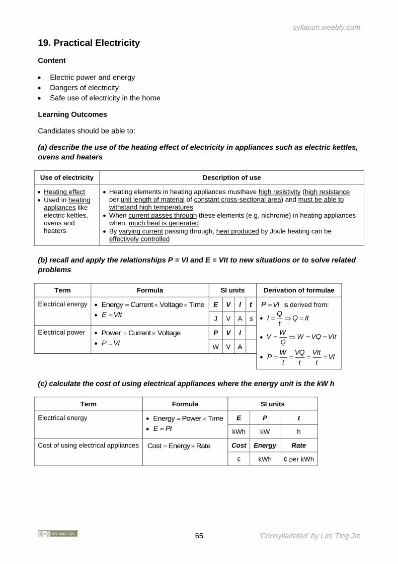
syllacon.weebly.com
65 ‘Consylladated’ by Lim Ting Jie
19. Practical Electricity
Content
• Electric power and energy
• Dangers of electricity
• Safe use of electricity in the home
Learning Outcomes
Candidates should be able to:
(a) describe the use of the heating effect of electricity in appliances such as electric kettles,
ovens and heaters
Use of electricity Description of use
• Heating effect
• Used in heating appliances like electric kettles, ovens and heaters
• Heating elements in heating appliances musthave high resistivity (high resistance per unit length of material of constant cross-sectional area) and must be able to withstand high temperatures
• When current passes through these elements (e.g. nichrome) in heating appliances when, much heat is generated
• By varying current passing through, heat produced by Joule heating can be effectively controlled
(b) recall and apply the relationships P = VI and E = VIt to new situations or to solve related
problems
Term Formula SI units Derivation of formulae
Electrical energy • Energy Current Voltage Time=
• E VIt=
E V I t P VI= is derived from:
• Q
I Q Itt
= =
• W
V W VQ VItQ
= = =
• W VQ VIt
P VIt t t
= = = =
J V A s
Electrical power • Power Current Voltage=
• P VI=
P V I
W V A
(c) calculate the cost of using electrical appliances where the energy unit is the kW h
Term Formula SI units
Electrical energy • Energy Power Time=
• E Pt=
E P t
kWh kW h
Cost of using electrical appliances Cost Energy Rate= Cost Energy Rate
¢ kWh ¢ per kWh
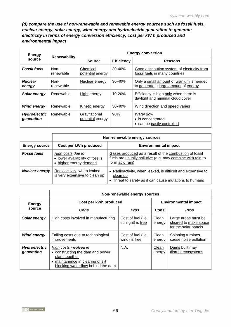
syllacon.weebly.com
66 ‘Consylladated’ by Lim Ting Jie
(d) compare the use of non-renewable and renewable energy sources such as fossil fuels,
nuclear energy, solar energy, wind energy and hydroelectric generation to generate
electricity in terms of energy conversion efficiency, cost per kW h produced and
environmental impact
Energy source
Renewability Energy conversion
Source Efficiency Reasons
Fossil fuels Non-renewable
Chemical potential energy
30-40% Good distribution system of electricity from fossil fuels in many countries
Nuclear energy
Non-renewable
Nuclear energy 30-40% Only a small amount of uranium is needed to generate a large amount of energy
Solar energy Renewable Light energy 10-20% Efficiency is high only when there is daylight and minimal cloud cover
Wind energy Renewable Kinetic energy 30-40% Wind direction and speed varies
Hydroelectric generation
Renewable Gravitational potential energy
90% Water flow
• is concentrated
• can be easily controlled
Non-renewable energy sources
Energy source Cost per kWh produced Environmental impact
Fossil fuels High costs due to
• lower availability of fossils
• higher energy demand
Gases produced as a result of the combustion of fossil fuels are usually pollutive (e.g. may combine with rain to form acid rain)
Nuclear energy Radioactivity, when leaked, is very expensive to clean up
• Radioactivity, when leaked, is difficult and expensive to clean up
• Threat to safety as it can cause mutations to humans
Non-renewable energy sources
Energy source
Cost per kWh produced Environmental impact
Cons Pros Cons Pros
Solar energy High costs involved in manufacturing Cost of fuel (i.e. sunlight) is free
Clean energy
Large areas must be cleared to make space for the solar panels
Wind energy Falling costs due to technological improvements
Cost of fuel (i.e. wind) is free
Clean energy
Spinning turbines cause noise pollution
Hydroelectric generation
High costs involved in
• constructing the dam and power plant together
• maintanence in clearing of slit blocking water flow behind the dam
N.A. Clean energy
Dams built may disrupt ecosystems
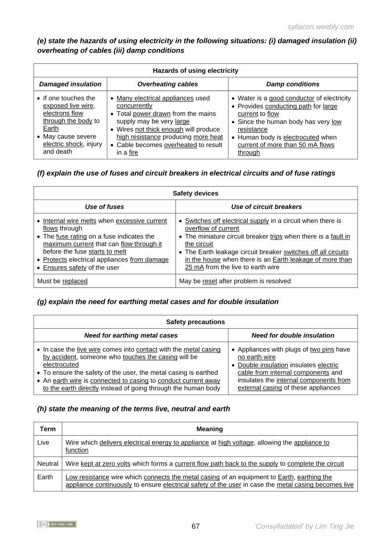
syllacon.weebly.com
67 ‘Consylladated’ by Lim Ting Jie
(e) state the hazards of using electricity in the following situations: (i) damaged insulation (ii)
overheating of cables (iii) damp conditions
Hazards of using electricity
Damaged insulation Overheating cables Damp conditions
• If one touches the exposed live wire, electrons flow through the body to Earth
• May cause severe electric shock, injury and death
• Many electrical appliances used concurrently
• Total power drawn from the mains supply may be very large
• Wires not thick enough will produce high resistance producing more heat
• Cable becomes overheated to result in a fire
• Water is a good conductor of electricity
• Provides conducting path for large current to flow
• Since the human body has very low resistance
• Human body is electrocuted when current of more than 50 mA flows through
(f) explain the use of fuses and circuit breakers in electrical circuits and of fuse ratings
Safety devices
Use of fuses Use of circuit breakers
• Internal wire melts when excessive current flows through
• The fuse rating on a fuse indicates the maximum current that can flow through it before the fuse starts to melt
• Protects electrical appliances from damage
• Ensures safety of the user
• Switches off electrical supply in a circuit when there is overflow of current
• The miniature circuit breaker trips when there is a fault in the circuit
• The Earth leakage circuit breaker switches off all circuits in the house when there is an Earth leakage of more than 25 mA from the live to earth wire
Must be replaced May be reset after problem is resolved
(g) explain the need for earthing metal cases and for double insulation
Safety precautions
Need for earthing metal cases Need for double insulation
• In case the live wire comes into contact with the metal casing by accident, someone who touches the casing will be electrocuted
• To ensure the safety of the user, the metal casing is earthed
• An earth wire is connected to casing to conduct current away to the earth directly instead of going through the human body
• Appliances with plugs of two pins have no earth wire
• Double insulation insulates electric cable from internal components and insulates the internal components from external casing of these appliances
(h) state the meaning of the terms live, neutral and earth
Term Meaning
Live Wire which delivers electrical energy to appliance at high voltage, allowing the appliance to function
Neutral Wire kept at zero volts which forms a current flow path back to the supply to complete the circuit
Earth Low resistance wire which connects the metal casing of an equipment to Earth, earthing the appliance continuously to ensure electrical safety of the user in case the metal casing becomes live
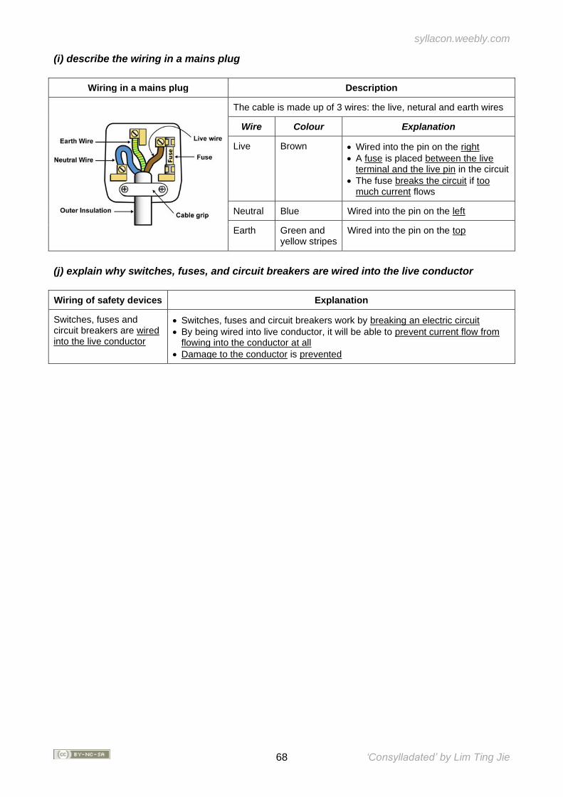
syllacon.weebly.com
68 ‘Consylladated’ by Lim Ting Jie
(i) describe the wiring in a mains plug
Wiring in a mains plug Description
The cable is made up of 3 wires: the live, netural and earth wires
Wire Colour Explanation
Live Brown • Wired into the pin on the right
• A fuse is placed between the live terminal and the live pin in the circuit
• The fuse breaks the circuit if too much current flows
Neutral Blue Wired into the pin on the left
Earth Green and yellow stripes
Wired into the pin on the top
(j) explain why switches, fuses, and circuit breakers are wired into the live conductor
Wiring of safety devices Explanation
Switches, fuses and circuit breakers are wired into the live conductor
• Switches, fuses and circuit breakers work by breaking an electric circuit
• By being wired into live conductor, it will be able to prevent current flow from flowing into the conductor at all
• Damage to the conductor is prevented
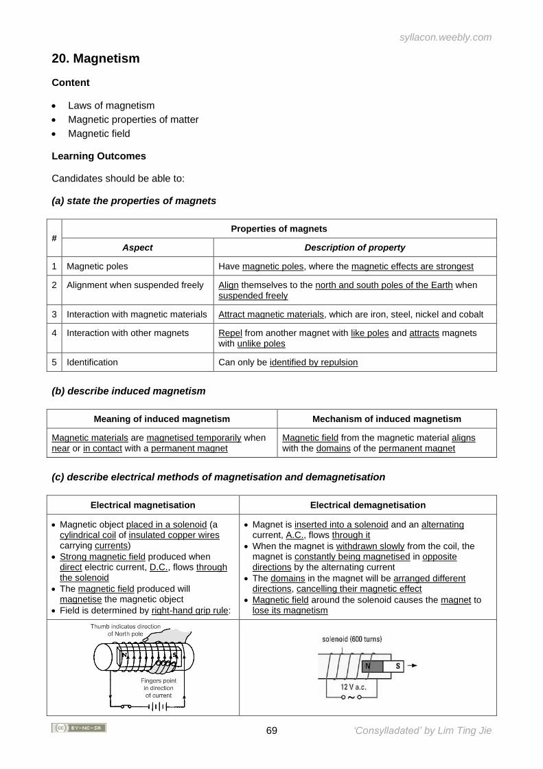
syllacon.weebly.com
69 ‘Consylladated’ by Lim Ting Jie
20. Magnetism
Content
• Laws of magnetism
• Magnetic properties of matter
• Magnetic field
Learning Outcomes
Candidates should be able to:
(a) state the properties of magnets
# Properties of magnets
Aspect Description of property
1 Magnetic poles Have magnetic poles, where the magnetic effects are strongest
2 Alignment when suspended freely Align themselves to the north and south poles of the Earth when suspended freely
3 Interaction with magnetic materials Attract magnetic materials, which are iron, steel, nickel and cobalt
4 Interaction with other magnets Repel from another magnet with like poles and attracts magnets with unlike poles
5 Identification Can only be identified by repulsion
(b) describe induced magnetism
Meaning of induced magnetism Mechanism of induced magnetism
Magnetic materials are magnetised temporarily when near or in contact with a permanent magnet
Magnetic field from the magnetic material aligns with the domains of the permanent magnet
(c) describe electrical methods of magnetisation and demagnetisation
Electrical magnetisation Electrical demagnetisation
• Magnetic object placed in a solenoid (a cylindrical coil of insulated copper wires carrying currents)
• Strong magnetic field produced when direct electric current, D.C., flows through the solenoid
• The magnetic field produced will magnetise the magnetic object
• Field is determined by right-hand grip rule:
• Magnet is inserted into a solenoid and an alternating current, A.C., flows through it
• When the magnet is withdrawn slowly from the coil, the magnet is constantly being magnetised in opposite directions by the alternating current
• The domains in the magnet will be arranged different directions, cancelling their magnetic effect
• Magnetic field around the solenoid causes the magnet to lose its magnetism
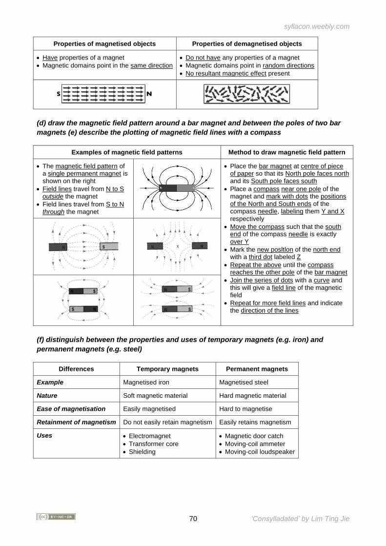
syllacon.weebly.com
70 ‘Consylladated’ by Lim Ting Jie
Properties of magnetised objects Properties of demagnetised objects
• Have properties of a magnet
• Magnetic domains point in the same direction
• Do not have any properties of a magnet
• Magnetic domains point in random directions
• No resultant magnetic effect present
(d) draw the magnetic field pattern around a bar magnet and between the poles of two bar
magnets (e) describe the plotting of magnetic field lines with a compass
Examples of magnetic field patterns Method to draw magnetic field pattern
• The magnetic field pattern of a single permanent magnet is shown on the right
• Field lines travel from N to S outside the magnet
• Field lines travel from S to N through the magnet
• Place the bar magnet at centre of piece of paper so that its North pole faces north and its South pole faces south
• Place a compass near one pole of the magnet and mark with dots the positions of the North and South ends of the compass needle, labeling them Y and X respectively
• Move the compass such that the south end of the compass needle is exactly over Y
• Mark the new posltlon of the north end with a third dot labeled Z
• Repeat the above until the compass reaches the other pole of the bar magnet
• Join the series of dots with a curve and this will give a field line of the magnetic field
• Repeat for more field lines and indicate the direction of the lines
(f) distinguish between the properties and uses of temporary magnets (e.g. iron) and
permanent magnets (e.g. steel)
Differences Temporary magnets Permanent magnets
Example Magnetised iron Magnetised steel
Nature Soft magnetic material Hard magnetic material
Ease of magnetisation Easily magnetised Hard to magnetise
Retainment of magnetism Do not easily retain magnetism Easily retains magnetism
Uses • Electromagnet
• Transformer core
• Shielding
• Magnetic door catch
• Moving-coil ammeter
• Moving-coil loudspeaker
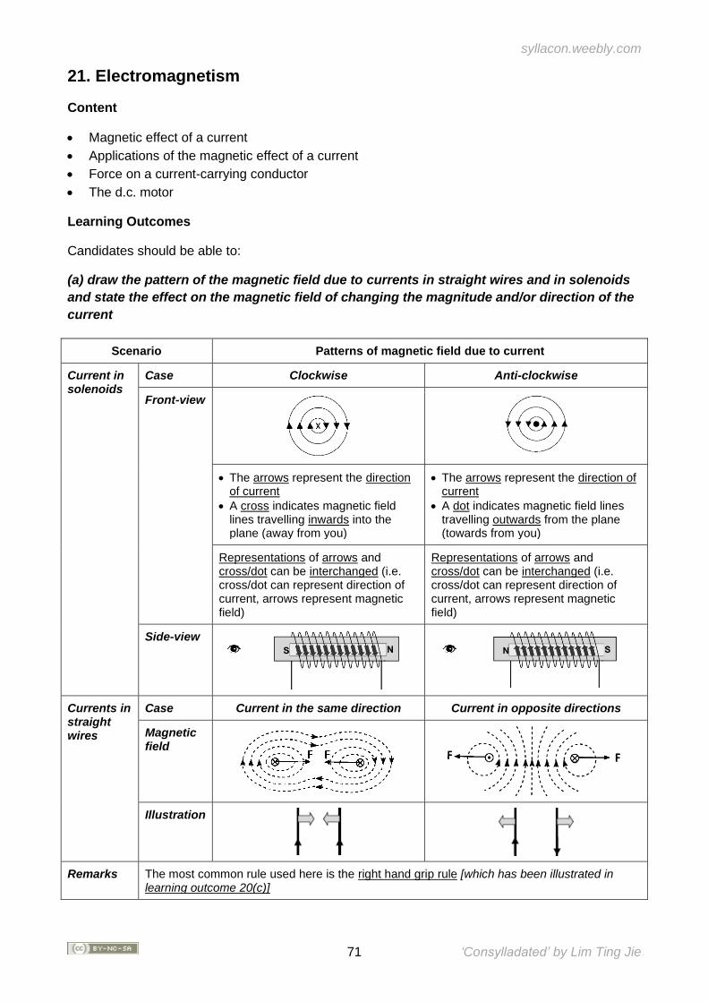
syllacon.weebly.com
71 ‘Consylladated’ by Lim Ting Jie
21. Electromagnetism
Content
• Magnetic effect of a current
• Applications of the magnetic effect of a current
• Force on a current-carrying conductor
• The d.c. motor
Learning Outcomes
Candidates should be able to:
(a) draw the pattern of the magnetic field due to currents in straight wires and in solenoids
and state the effect on the magnetic field of changing the magnitude and/or direction of the
current
Scenario Patterns of magnetic field due to current
Current in solenoids
Case Clockwise Anti-clockwise
Front-view
• The arrows represent the direction of current
• A cross indicates magnetic field lines travelling inwards into the plane (away from you)
• The arrows represent the direction of current
• A dot indicates magnetic field lines travelling outwards from the plane (towards from you)
Representations of arrows and cross/dot can be interchanged (i.e. cross/dot can represent direction of current, arrows represent magnetic field)
Representations of arrows and cross/dot can be interchanged (i.e. cross/dot can represent direction of current, arrows represent magnetic field)
Side-view
Currents in straight wires
Case Current in the same direction Current in opposite directions
Magnetic field
Illustration
Remarks The most common rule used here is the right hand grip rule [which has been illustrated in learning outcome 20(c)]
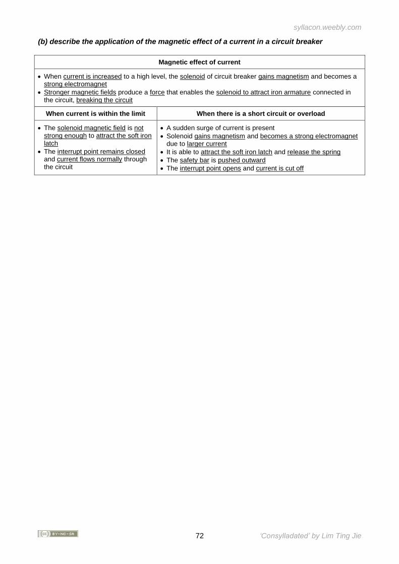
syllacon.weebly.com
72 ‘Consylladated’ by Lim Ting Jie
(b) describe the application of the magnetic effect of a current in a circuit breaker
Magnetic effect of current
• When current is increased to a high level, the solenoid of circuit breaker gains magnetism and becomes a strong electromagnet
• Stronger magnetic fields produce a force that enables the solenoid to attract iron armature connected in the circuit, breaking the circuit
When current is within the limit When there is a short circuit or overload
• The solenoid magnetic field is not strong enough to attract the soft iron latch
• The interrupt point remains closed and current flows normally through the circuit
• A sudden surge of current is present
• Solenoid gains magnetism and becomes a strong electromagnet due to larger current
• It is able to attract the soft iron latch and release the spring
• The safety bar is pushed outward
• The interrupt point opens and current is cut off
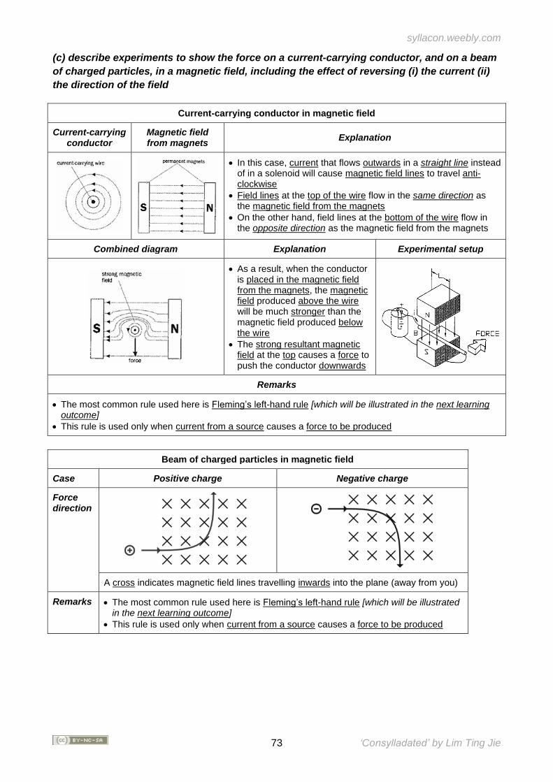
syllacon.weebly.com
73 ‘Consylladated’ by Lim Ting Jie
(c) describe experiments to show the force on a current-carrying conductor, and on a beam
of charged particles, in a magnetic field, including the effect of reversing (i) the current (ii)
the direction of the field
Current-carrying conductor in magnetic field
Current-carrying conductor
Magnetic field from magnets
Explanation
• In this case, current that flows outwards in a straight line instead of in a solenoid will cause magnetic field lines to travel anti-clockwise
• Field lines at the top of the wire flow in the same direction as the magnetic field from the magnets
• On the other hand, field lines at the bottom of the wire flow in the opposite direction as the magnetic field from the magnets
Combined diagram Explanation Experimental setup
• As a result, when the conductor is placed in the magnetic field from the magnets, the magnetic field produced above the wire will be much stronger than the magnetic field produced below the wire
• The strong resultant magnetic field at the top causes a force to push the conductor downwards
Remarks
• The most common rule used here is Fleming’s left-hand rule [which will be illustrated in the next learning outcome]
• This rule is used only when current from a source causes a force to be produced
Beam of charged particles in magnetic field
Case Positive charge Negative charge
Force direction
A cross indicates magnetic field lines travelling inwards into the plane (away from you)
Remarks • The most common rule used here is Fleming’s left-hand rule [which will be illustrated in the next learning outcome]
• This rule is used only when current from a source causes a force to be produced
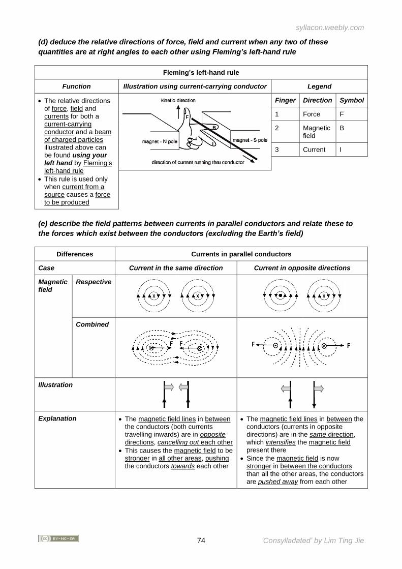
syllacon.weebly.com
74 ‘Consylladated’ by Lim Ting Jie
(d) deduce the relative directions of force, field and current when any two of these
quantities are at right angles to each other using Fleming’s left-hand rule
Fleming’s left-hand rule
Function Illustration using current-carrying conductor Legend
• The relative directions of force, field and currents for both a current-carrying conductor and a beam of charged particles illustrated above can be found using your left hand by Fleming’s left-hand rule
• This rule is used only when current from a source causes a force to be produced
Finger Direction Symbol
1 Force F
2 Magnetic field
B
3 Current I
(e) describe the field patterns between currents in parallel conductors and relate these to
the forces which exist between the conductors (excluding the Earth’s field)
Differences Currents in parallel conductors
Case Current in the same direction Current in opposite directions
Magnetic field
Respective
Combined
Illustration
Explanation • The magnetic field lines in between the conductors (both currents travelling inwards) are in opposite directions, cancelling out each other
• This causes the magnetic field to be stronger in all other areas, pushing the conductors towards each other
• The magnetic field lines in between the conductors (currents in opposite directions) are in the same direction, which intensifies the magnetic field present there
• Since the magnetic field is now stronger in between the conductors than all the other areas, the conductors are pushed away from each other
F
B
I
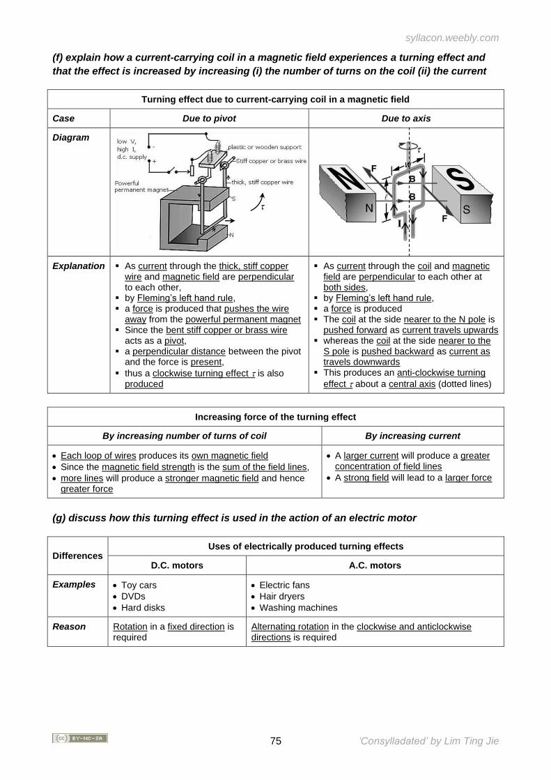
syllacon.weebly.com
75 ‘Consylladated’ by Lim Ting Jie
(f) explain how a current-carrying coil in a magnetic field experiences a turning effect and
that the effect is increased by increasing (i) the number of turns on the coil (ii) the current
Turning effect due to current-carrying coil in a magnetic field
Case Due to pivot Due to axis
Diagram
Explanation ▪ As current through the thick, stiff copper wire and magnetic field are perpendicular to each other,
▪ by Fleming’s left hand rule, ▪ a force is produced that pushes the wire
away from the powerful permanent magnet ▪ Since the bent stiff copper or brass wire
acts as a pivot, ▪ a perpendicular distance between the pivot
and the force is present,
▪ thus a clockwise turning effect is also produced
▪ As current through the coil and magnetic field are perpendicular to each other at both sides,
▪ by Fleming’s left hand rule, ▪ a force is produced ▪ The coil at the side nearer to the N pole is
pushed forward as current travels upwards ▪ whereas the coil at the side nearer to the
S pole is pushed backward as current as travels downwards
▪ This produces an anti-clockwise turning
effect about a central axis (dotted lines)
Increasing force of the turning effect
By increasing number of turns of coil By increasing current
• Each loop of wires produces its own magnetic field
• Since the magnetic field strength is the sum of the field lines,
• more lines will produce a stronger magnetic field and hence greater force
• A larger current will produce a greater concentration of field lines
• A strong field will lead to a larger force
(g) discuss how this turning effect is used in the action of an electric motor
Differences Uses of electrically produced turning effects
D.C. motors A.C. motors
Examples • Toy cars
• DVDs
• Hard disks
• Electric fans
• Hair dryers
• Washing machines
Reason Rotation in a fixed direction is required
Alternating rotation in the clockwise and anticlockwise directions is required
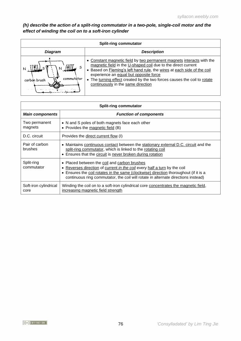
syllacon.weebly.com
76 ‘Consylladated’ by Lim Ting Jie
(h) describe the action of a split-ring commutator in a two-pole, single-coil motor and the
effect of winding the coil on to a soft-iron cylinder
Split-ring commutator
Diagram Description
• Constant magnetic field by two permanent magnets interacts with the magnetic field in the U-shaped coil due to the direct current
• Based on Fleming’s left hand rule, the wires at each side of the coil experience an equal but opposite force
• The turning effect created by the two forces causes the coil to rotate continuously in the same direction
Split-ring commutator
Main components Function of components
Two permanent magnets
• N and S poles of both magnets face each other
• Provides the magnetic field (B)
D.C. circuit Provides the direct current flow (I)
Pair of carbon brushes
• Maintains continuous contact between the stationary external D.C. circuit and the split-ring commutator, which is linked to the rotating coil
• Ensures that the circuit is never broken during rotation
Split-ring commutator
• Placed between the coil and carbon brushes
• Reverses direction of current in the coil every half a turn by the coil
• Ensures the coil rotates in the same (clockwise) direction thoroughout (if it is a continuous ring commutator, the coil will rotate in alternate directions instead)
Soft-iron cylindrical core
Winding the coil on to a soft-iron cylindrical core concentrates the magnetic field, increasing magnetic field strength
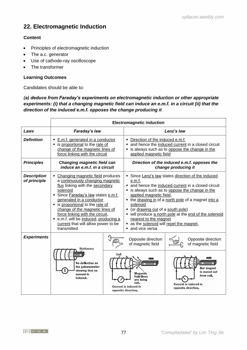
syllacon.weebly.com
77 ‘Consylladated’ by Lim Ting Jie
22. Electromagnetic Induction
Content
• Principles of electromagnetic induction
• The a.c. generator
• Use of cathode-ray oscilloscope
• The transformer
Learning Outcomes
Candidates should be able to:
(a) deduce from Faraday’s experiments on electromagnetic induction or other appropriate
experiments: (i) that a changing magnetic field can induce an e.m.f. in a circuit (ii) that the
direction of the induced e.m.f. opposes the change producing it
Electromagnetic induction
Laws Faraday’s law Lenz’s law
Definition ▪ E.m.f. generated in a conductor ▪ is proportional to the rate of
change of the magnetic lines of force linking with the circuit
▪ Direction of the induced e.m.f. ▪ and hence the induced current in a closed circuit ▪ is always such as to oppose the change in the
applied magnetic field
Principles Changing magnetic field can induce an e.m.f. in a circuit
Direction of the induced e.m.f. opposes the change producing it
Description of principle
▪ Changing magnetic field produces a continuously changing magnetic flux linking with the secondary solenoid
▪ Since Faraday’s law states e.m.f. generated in a conductor
▪ is proportional to the rate of change of the magnetic lines of force linking with the circuit,
▪ e.m.f. will be induced, producing a current that will allow power to be transmitted
▪ Since Lenz’s law states direction of the induced e.m.f.
▪ and hence the induced current in a closed circuit ▪ is always such as to oppose the change in the
applied magnetic field, ▪ the drawing in of a north pole of a magnet into a
solenoid ▪ (or drawing out of a south pole) ▪ will produce a north pole at the end of the solenoid
nearest to the magnet ▪ as the solenoid will repel the magnet, ▪ and vice versa
Experiments
Opposite direction of magnetic field
Opposite direction of magnetic field
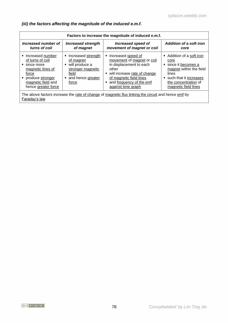
syllacon.weebly.com
78 ‘Consylladated’ by Lim Ting Jie
(iii) the factors affecting the magnitude of the induced e.m.f.
Factors to increase the magnitude of induced e.m.f.
Increased number of turns of coil
Increased strength of magnet
Increased speed of movement of magnet or coil
Addition of a soft iron core
▪ Increased number of turns of coil
▪ since more magnetic lines of force
▪ produce stronger magnetic field and hence greater force
▪ Increased strength of magnet
▪ will produce a stronger magnetic field
▪ and hence greater force
▪ Increased speed of movement of magnet or coil in displacement to each other
▪ will increase rate of change of magnetic field lines
▪ and frequency of the emf against time graph
▪ Addition of a soft iron core
▪ since it becomes a magnet within the field lines
▪ such that it increases the concentration of magnetic field lines
The above factors increase the rate of change of magnetic flux linking the circuit and hence emf by Faraday’s law
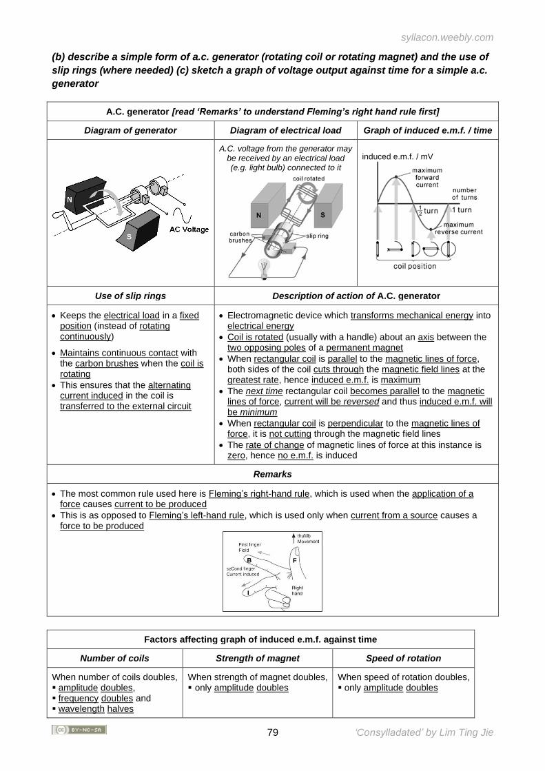
syllacon.weebly.com
79 ‘Consylladated’ by Lim Ting Jie
(b) describe a simple form of a.c. generator (rotating coil or rotating magnet) and the use of
slip rings (where needed) (c) sketch a graph of voltage output against time for a simple a.c.
generator
A.C. generator [read ‘Remarks’ to understand Fleming’s right hand rule first]
Diagram of generator Diagram of electrical load Graph of induced e.m.f. / time
A.C. voltage from the generator may be received by an electrical load (e.g. light bulb) connected to it
Use of slip rings Description of action of A.C. generator
• Keeps the electrical load in a fixed position (instead of rotating continuously)
• Maintains continuous contact with the carbon brushes when the coil is rotating
• This ensures that the alternating current induced in the coil is transferred to the external circuit
• Electromagnetic device which transforms mechanical energy into electrical energy
• Coil is rotated (usually with a handle) about an axis between the two opposing poles of a permanent magnet
• When rectangular coil is parallel to the magnetic lines of force, both sides of the coil cuts through the magnetic field lines at the greatest rate, hence induced e.m.f. is maximum
• The next time rectangular coil becomes parallel to the magnetic lines of force, current will be reversed and thus induced e.m.f. will be minimum
• When rectangular coil is perpendicular to the magnetic lines of force, it is not cutting through the magnetic field lines
• The rate of change of magnetic lines of force at this instance is zero, hence no e.m.f. is induced
Remarks
• The most common rule used here is Fleming’s right-hand rule, which is used when the application of a force causes current to be produced
• This is as opposed to Fleming’s left-hand rule, which is used only when current from a source causes a force to be produced
Factors affecting graph of induced e.m.f. against time
Number of coils Strength of magnet Speed of rotation
When number of coils doubles, ▪ amplitude doubles, ▪ frequency doubles and ▪ wavelength halves
When strength of magnet doubles, ▪ only amplitude doubles
When speed of rotation doubles, ▪ only amplitude doubles
induced e.m.f. / mV
F B
I
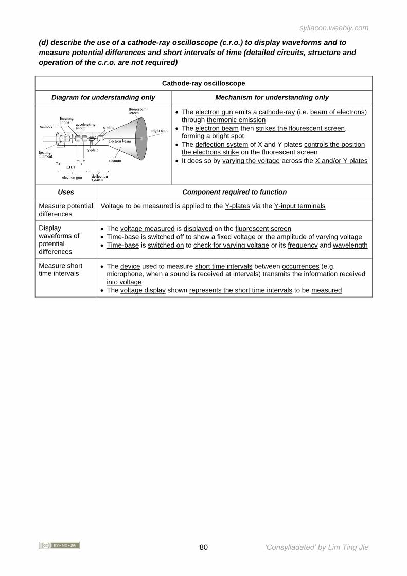
syllacon.weebly.com
80 ‘Consylladated’ by Lim Ting Jie
(d) describe the use of a cathode-ray oscilloscope (c.r.o.) to display waveforms and to
measure potential differences and short intervals of time (detailed circuits, structure and
operation of the c.r.o. are not required)
Cathode-ray oscilloscope
Diagram for understanding only Mechanism for understanding only
• The electron gun emits a cathode-ray (i.e. beam of electrons) through thermonic emission
• The electron beam then strikes the flourescent screen, forming a bright spot
• The deflection system of X and Y plates controls the position the electrons strike on the fluorescent screen
• It does so by varying the voltage across the X and/or Y plates
Uses Component required to function
Measure potential differences
Voltage to be measured is applied to the Y-plates via the Y-input terminals
Display waveforms of potential differences
• The voltage measured is displayed on the fluorescent screen
• Time-base is switched off to show a fixed voltage or the amplitude of varying voltage
• Time-base is switched on to check for varying voltage or its frequency and wavelength
Measure short time intervals
• The device used to measure short time intervals between occurrences (e.g. microphone, when a sound is received at intervals) transmits the information received into voltage
• The voltage display shown represents the short time intervals to be measured
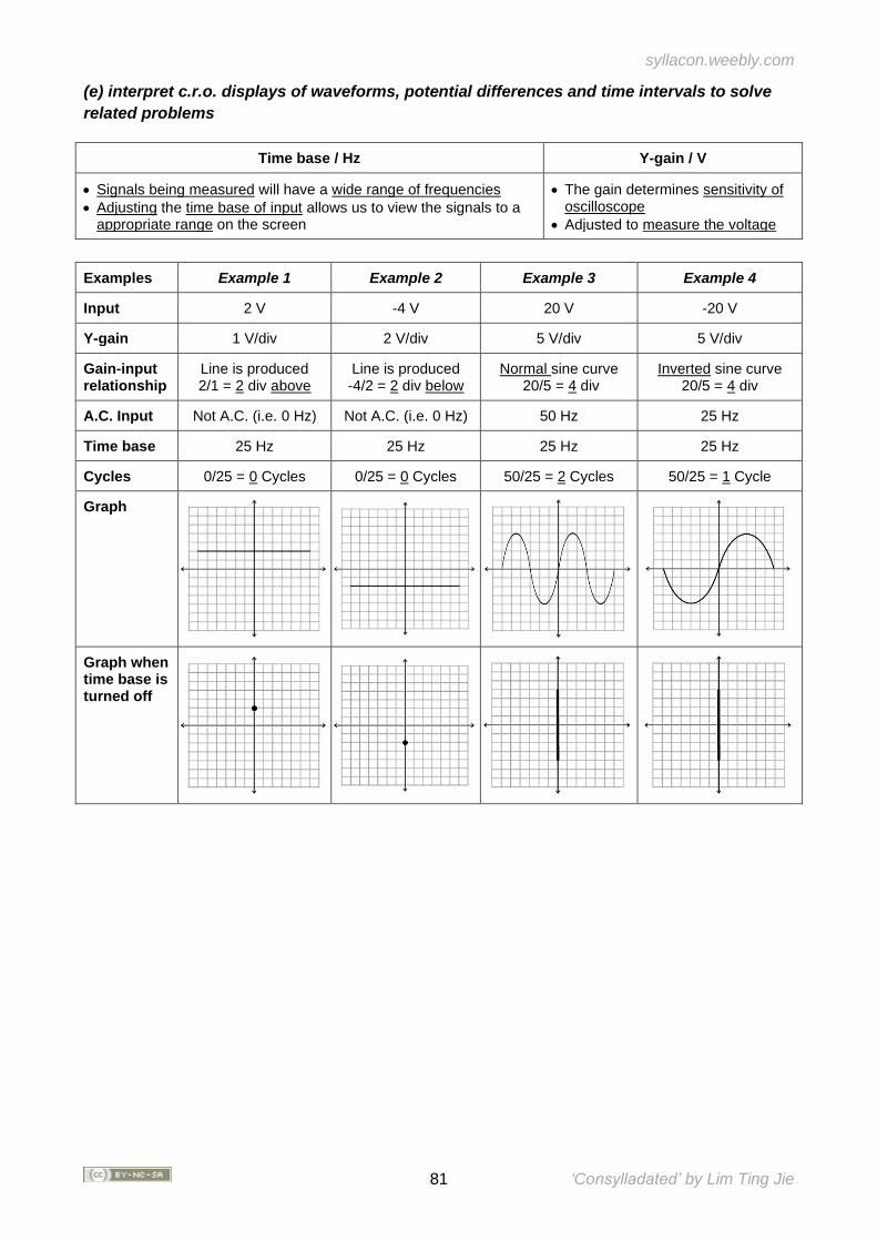
syllacon.weebly.com
81 ‘Consylladated’ by Lim Ting Jie
(e) interpret c.r.o. displays of waveforms, potential differences and time intervals to solve
related problems
Time base / Hz Y-gain / V
• Signals being measured will have a wide range of frequencies
• Adjusting the time base of input allows us to view the signals to a appropriate range on the screen
• The gain determines sensitivity of oscilloscope
• Adjusted to measure the voltage
Examples Example 1 Example 2 Example 3 Example 4
Input 2 V -4 V 20 V -20 V
Y-gain 1 V/div 2 V/div 5 V/div 5 V/div
Gain-input relationship
Line is produced 2/1 = 2 div above
Line is produced -4/2 = 2 div below
Normal sine curve 20/5 = 4 div
Inverted sine curve 20/5 = 4 div
A.C. Input Not A.C. (i.e. 0 Hz) Not A.C. (i.e. 0 Hz) 50 Hz 25 Hz
Time base 25 Hz 25 Hz 25 Hz 25 Hz
Cycles 0/25 = 0 Cycles 0/25 = 0 Cycles 50/25 = 2 Cycles 50/25 = 1 Cycle
Graph
Graph when time base is turned off
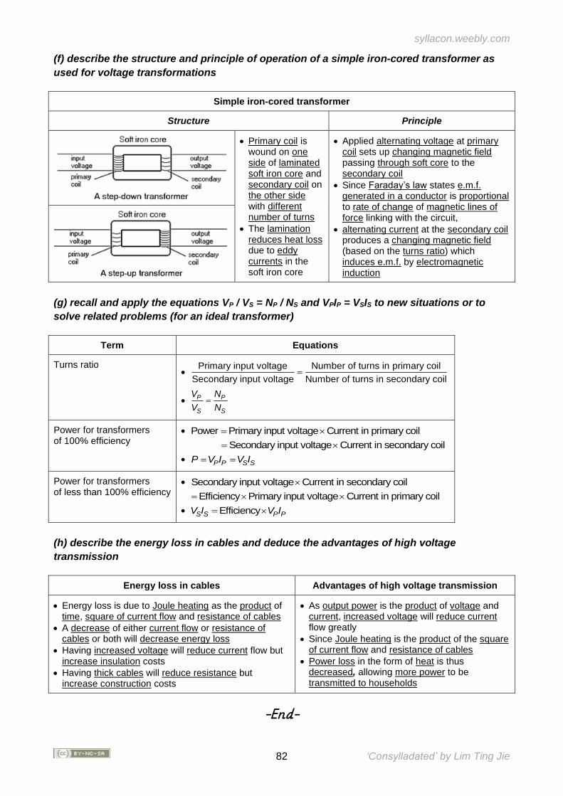
syllacon.weebly.com
82 ‘Consylladated’ by Lim Ting Jie
(f) describe the structure and principle of operation of a simple iron-cored transformer as
used for voltage transformations
Simple iron-cored transformer
Structure Principle
• Primary coil is wound on one side of laminated soft iron core and secondary coil on the other side with different number of turns
• The lamination reduces heat loss due to eddy currents in the soft iron core
• Applied alternating voltage at primary coil sets up changing magnetic field passing through soft core to the secondary coil
• Since Faraday’s law states e.m.f. generated in a conductor is proportional to rate of change of magnetic lines of force linking with the circuit,
• alternating current at the secondary coil produces a changing magnetic field (based on the turns ratio) which induces e.m.f. by electromagnetic induction
(g) recall and apply the equations VP / VS = NP / NS and VPIP = VSIS to new situations or to
solve related problems (for an ideal transformer)
Term Equations
Turns ratio •
Primary input voltage Number of turns in primary coil
Secondary input voltage Number of turns in secondary coil=
• P P
S S
V N
V N=
Power for transformers of 100% efficiency
• Power Primary input voltage Current in primary coil=
Secondary input voltage Current in secondary coil=
• P P S SP V I V I= =
Power for transformers of less than 100% efficiency
• Secondary input voltage Current in secondary coil
Efficiency Primary input voltage Current in primary coil=
• EfficiencyS S P PV I V I=
(h) describe the energy loss in cables and deduce the advantages of high voltage
transmission
Energy loss in cables Advantages of high voltage transmission
• Energy loss is due to Joule heating as the product of time, square of current flow and resistance of cables
• A decrease of either current flow or resistance of cables or both will decrease energy loss
• Having increased voltage will reduce current flow but increase insulation costs
• Having thick cables will reduce resistance but increase construction costs
• As output power is the product of voltage and current, increased voltage will reduce current flow greatly
• Since Joule heating is the product of the square of current flow and resistance of cables
• Power loss in the form of heat is thus decreased, allowing more power to be transmitted to households
-End-
syllacon.weebly.com
83 ‘Consylladated’ by Lim Ting Jie
Notice
While every effort has been made to avoid using copyright material, some copyright material may
have been inadvertently used in this set of notes. To these copyright holders, we offer our sincere
apologies and hope they will take our liberty in good faith. We would welcome any information
which would enable us to contact the copyright owners involved.
Under the Creative Commons licence,
Editors are free to:
Share — copy and redistribute the material in any medium or format
Adapt — remix, transform, and build upon the material
Under the following terms:
Attribution — You must give appropriate credit, provide a link to the license, and indicate if
changes were made. You may do so in any reasonable manner, but not in any way that suggests
the licensor endorses you or your use.
NonCommercial — You may not use the material for commercial purposes.
ShareAlike — If you remix, transform, or build upon the material, you must distribute your
contributions under the same license as the original.
Editors should ensure that any material they wish to embed in this set of notes is not copyrighted
before proceeding with editing.


![Bio Soil Interactions Engineering Workshop1].pdf · Bio‐Soil Interactions & Engineering Workshop ... Notes. Notes. Notes. Notes. Notes. Notes. ... Electrokinetic and Electrolytic](https://img.pdfslide.us/doc/110x75/5e7be480f39bf41290742405/bio-soil-interactions-engineering-workshop-1pdf-bioasoil-interactions-.jpg)


![notes NOTES ]” BACKGROUND](https://img.pdfslide.us/doc/110x75/61bd44c661276e740b111621/notes-notes-background.jpg)