Embed Size (px)
DESCRIPTION
Syllabus and slides. Lecture 1: Overview and history of Particle accelerators (EW) Lecture 2: Beam optics I (transverse) (EW) Lecture 3: Beam optics II (longitudinal) (EW) Lecture 4: Liouville's theorem and Emittance (RB) Lecture 5: Beam Optics and Imperfections (RB) - PowerPoint PPT Presentation
Citation preview
Syllabus and slidesSyllabus and slides
• Lecture 1: Overview and history of Particle accelerators (EW)• Lecture 2: Beam optics I (transverse) (EW)• Lecture 3: Beam optics II (longitudinal) (EW)• Lecture 4: Liouville's theorem and Emittance (RB)• Lecture 5: Beam Optics and Imperfections (RB)• Lecture 6: Beam Optics in linac (Compression) (RB)• Lecture 7: Synchrotron radiation (RB)• Lecture 8: Beam instabilities (RB)• Lecture 9: Space charge (RB)• Lecture 10: RF (ET)• Lecture 11: Beam diagnostics (ET)• Lecture 12: Accelerator Applications (Particle Physics) (ET)• Visit of Diamond Light Source/ ISIS / (some hospital if possible)
The slides of the lectures are available at
http://www.adams-institute.ac.uk/training/undergraduate
Dr. Riccardo Bartolini (DWB room 622) [email protected]
2/32
Lecture 8: wakefields and basic principles of beam instability
Beam Instabilities
High current operation in storage rings
Wakefields
Single bunch effects
Multi-bunch effects
Numerical analysis of instabilities with tracking codes
“Good wakefields”
Plasma Wakefield accelerators
R. Bartolini, John Adams Institute, 9 May 2013
Wakefields and collective effects
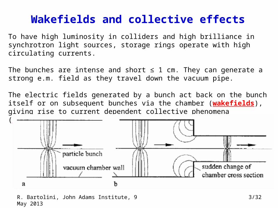
To have high luminosity in colliders and high brilliance in synchrotron light sources, storage rings operate with high circulating currents.
The bunches are intense and short ≤ 1 cm. They can generate a strong e.m. field as they travel down the vacuum pipe.
The electric fields generated by a bunch act back on the bunch itself or on subsequent bunches via the chamber (wakefields), giving rise to current dependent collective phenomena (collective effects).
3/32R. Bartolini, John Adams Institute, 9 May 2013
Collective effectsCollective effects
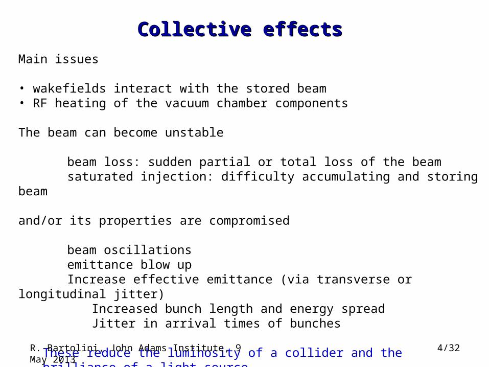
Main issues
• wakefields interact with the stored beam• RF heating of the vacuum chamber components
The beam can become unstable
beam loss: sudden partial or total loss of the beamsaturated injection: difficulty accumulating and storing beam
and/or its properties are compromised
beam oscillationsemittance blow upIncrease effective emittance (via transverse or longitudinal jitter)
Increased bunch length and energy spreadJitter in arrival times of bunches
These reduce the luminosity of a collider and the brilliance of a light source
R. Bartolini, John Adams Institute, 9 May 2013 4/32
5/32
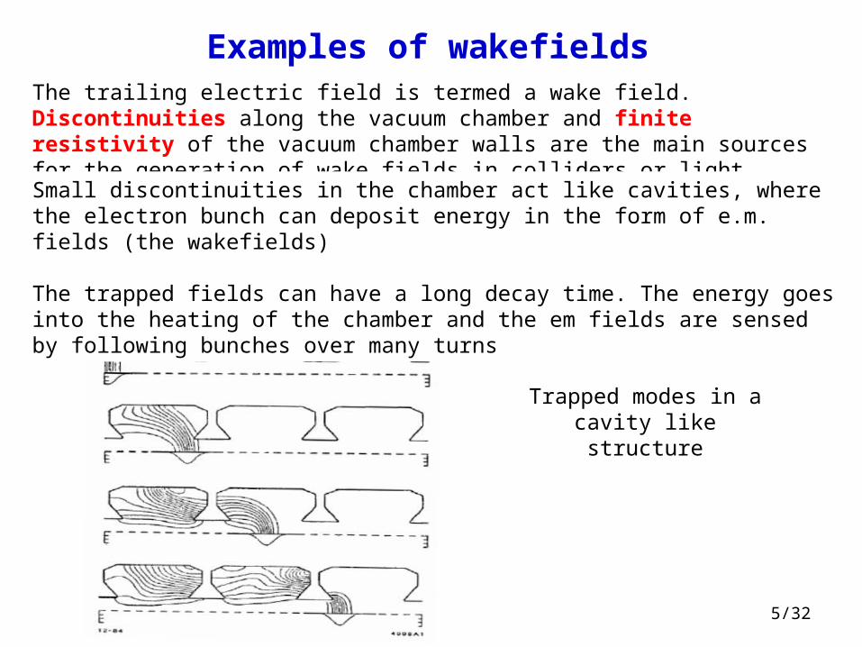
Examples of wakefieldsThe trailing electric field is termed a wake field. Discontinuities along the vacuum chamber and finite resistivity of the vacuum chamber walls are the main sources for the generation of wake fields in colliders or light sources
Small discontinuities in the chamber act like cavities, where the electron bunch can deposit energy in the form of e.m. fields (the wakefields)
The trapped fields can have a long decay time. The energy goes into the heating of the chamber and the em fields are sensed by following bunches over many turns
Trapped modes in a cavity like structure
6/32
Collective effects: examples
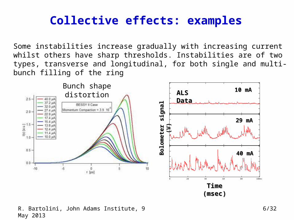
Some instabilities increase gradually with increasing current whilst others have sharp thresholds. Instabilities are of two types, transverse and longitudinal, for both single and multi-bunch filling of the ring
10.5mA
28.8mA
100ms806040200
Time (msec)
40.0mA
10 mA10 mA
29 mA29 mA
40 mA40 mA
Time (msec)Time (msec)
Bo
lom
eter
sig
nal
(V
)B
olo
met
er s
ign
al (
V)
ALS DataALS DataBunch shape distortion
R. Bartolini, John Adams Institute, 9 May 2013
Example: CSR in storage ringsExample: CSR in storage rings
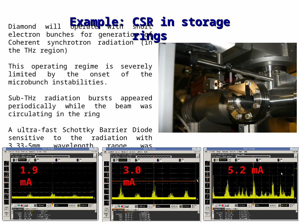
Diamond will operate with short electron bunches for generation of Coherent synchrotron radiation (in the THz region)
This operating regime is severely limited by the onset of the microbunch instabilities.
Sub-THz radiation bursts appeared periodically while the beam was circulating in the ring
A ultra-fast Schottky Barrier Diode sensitive to the radiation with 3.33-5mm wavelength range was installed in a dipole beamport;
1.9 mA 3.0 mA 5.2 mA
Transverse beam instabilitiesTransverse beam instabilities
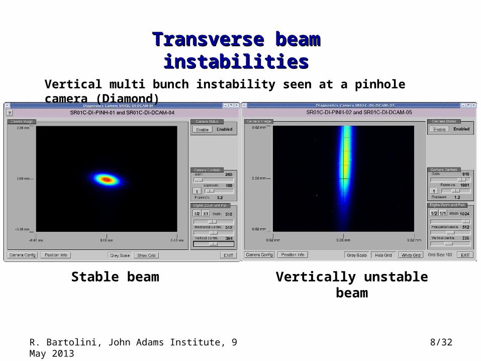
Stable beam Vertically unstable beam
8/32R. Bartolini, John Adams Institute, 9 May 2013
Vertical multi bunch instability seen at a pinhole camera (Diamond)
9/32
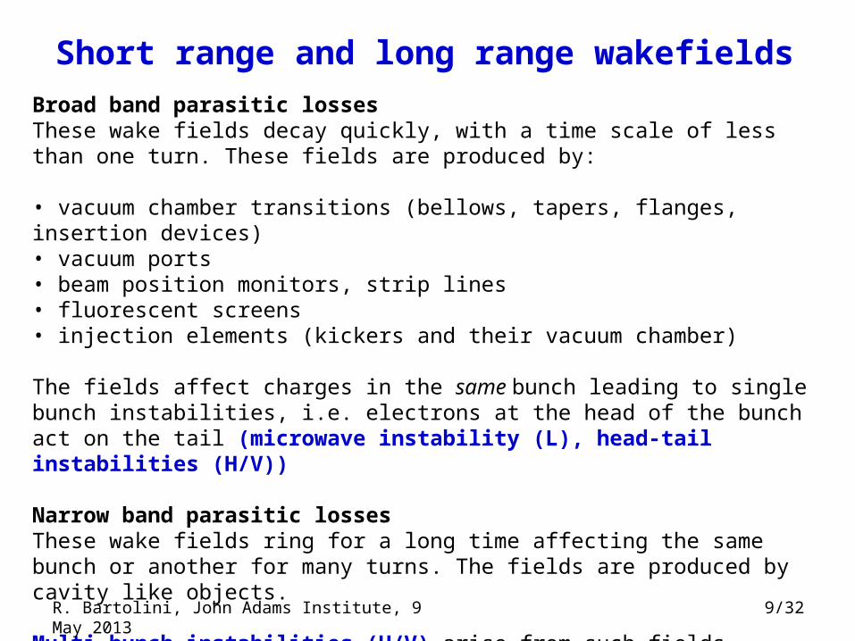
Short range and long range wakefields
Broad band parasitic lossesThese wake fields decay quickly, with a time scale of less than one turn. These fields are produced by:
• vacuum chamber transitions (bellows, tapers, flanges, insertion devices)• vacuum ports• beam position monitors, strip lines• fluorescent screens• injection elements (kickers and their vacuum chamber)
The fields affect charges in the same bunch leading to single bunch instabilities, i.e. electrons at the head of the bunch act on the tail (microwave instability (L), head-tail instabilities (H/V))
Narrow band parasitic lossesThese wake fields ring for a long time affecting the same bunch or another for many turns. The fields are produced by cavity like objects.
Multi-bunch instabilities (H/V) arise from such fields.
R. Bartolini, John Adams Institute, 9 May 2013
10/33
Computation of Wakefields (I)In its full generality, the computation of the wakefields generated by a bunch of charged particles is a very complex electromagnetic problem.
It requires the solution of the Maxwell’s equations with given source terms and boundary conditions imposed by the vacuum chamber
It is a 3D, time dependent problem that should be solved self consistently, i.e. the equation of the e.m. field are coupled to the equation of motion of the charged particles, so that the driving terms (charge and current densities) are also changing with time.
PIC codes runs, for complex EM problems, may take many weeks of CPU time !!! Finite elements codes also require an intensive computational effort despite some simplifying approximations customarily used to deal with this problem:
• the wakefields are computed assuming that the bunch distribution does not change under the action of the wakefields themselves in the structure
• the charge particle beam is assumed to be ultra-relativistic (v ~ c)
• the net effect of the wakefield on each particle is assumed to be small and is computed with the momentum transfer of the particle in the structure
• where possible, symmetric geometry allows the simplification of the problem.
11/32
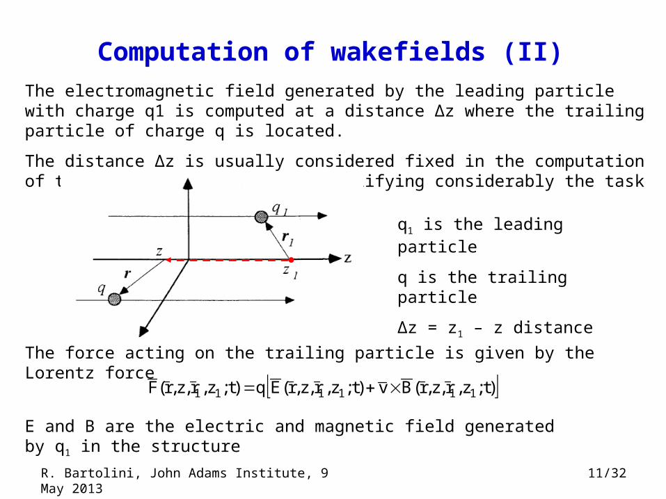
Computation of wakefields (II)The electromagnetic field generated by the leading particle with charge q1 is computed at a distance Δz where the trailing particle of charge q is located.
The distance Δz is usually considered fixed in the computation of the wakefield. This helps simplifying considerably the task
)t;z,r,z,r(Bv)t;z,r,z,r(Eq)t;z,r,z,r(F 111111
q1 is the leading particle
q is the trailing particle
Δz = z1 – z distance
The force acting on the trailing particle is given by the Lorentz force
E and B are the electric and magnetic field generated by q1 in the structure
R. Bartolini, John Adams Institute, 9 May 2013
12/32
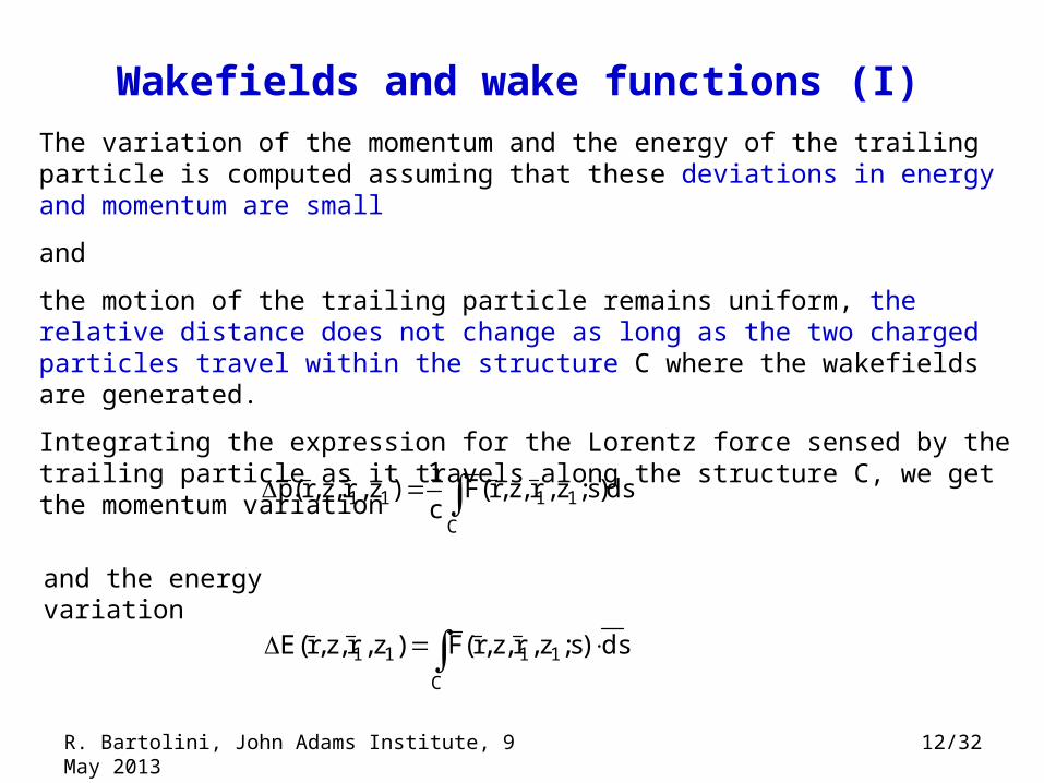
Wakefields and wake functions (I)
C
1111 ds)s;z,r,z,r(Fc
1)z,r,z,r(p
C
1111 ds)s;z,r,z,r(F)z,r,z,r(E
The variation of the momentum and the energy of the trailing particle is computed assuming that these deviations in energy and momentum are small
and
the motion of the trailing particle remains uniform, the relative distance does not change as long as the two charged particles travel within the structure C where the wakefields are generated.
Integrating the expression for the Lorentz force sensed by the trailing particle as it travels along the structure C, we get the momentum variation
and the energy variation
R. Bartolini, John Adams Institute, 9 May 2013
13/32
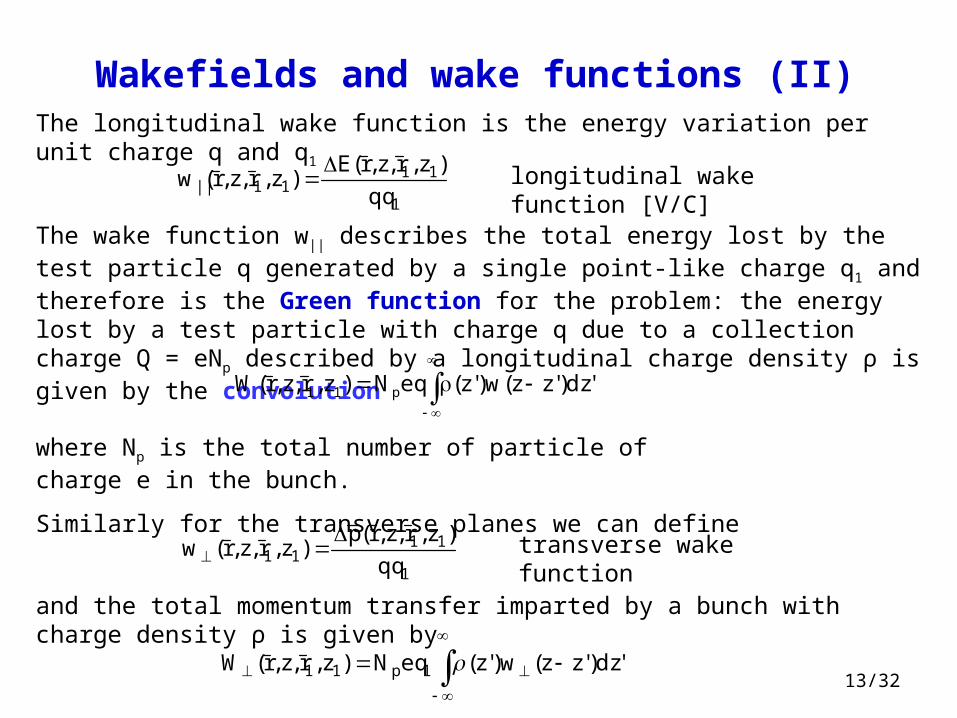
Wakefields and wake functions (II)
The wake function w|| describes the total energy lost by the test particle q generated by a single point-like charge q1 and therefore is the Green function for the problem: the energy lost by a test particle with charge q due to a collection charge Q = eNp described by a longitudinal charge density ρ is given by the convolution
'dz)'zz(w)'z(eqN)z,r,z,r(W p11
where Np is the total number of particle of charge e in the bunch.
Similarly for the transverse planes we can define
The longitudinal wake function is the energy variation per unit charge q and q1
1
1111|| qq
)z,r,z,r(E)z,r,z,r(w
longitudinal wake function [V/C]
1
1111 qq
)z,r,z,r(p)z,r,z,r(w
transverse wake function
and the total momentum transfer imparted by a bunch with charge density ρ is given by
'dz)'zz(w)'z(eqN)z,r,z,r(W 1p11
14/32
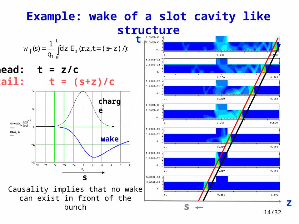
Causality implies that no wake can exist in front of the bunch
Example: wake of a slot cavity like structure
L
0
z1
|| )z)/c(st,z,r(Edzq
1)s(w
head: t = z/ctail: t = (s+z)/c
z
t
s
charge
wake
s
15/32
Coupling impedance
de)();'r,r(Z
q2
1)z;'r,r(W c
zi
||1
||
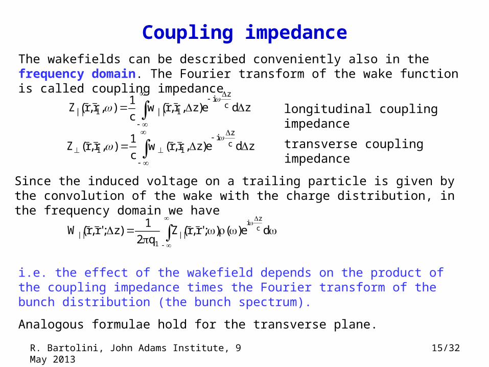
Since the induced voltage on a trailing particle is given by the convolution of the wake with the charge distribution, in the frequency domain we have
zde)z,r,r(wc
1),r,r(Z c
zi
1||1||
The wakefields can be described conveniently also in the frequency domain. The Fourier transform of the wake function is called coupling impedance
longitudinal coupling impedance
zde)z,r,r(wc
1),r,r(Z c
zi
11
transverse coupling impedance
i.e. the effect of the wakefield depends on the product of the coupling impedance times the Fourier transform of the bunch distribution (the bunch spectrum).
Analogous formulae hold for the transverse plane.
R. Bartolini, John Adams Institute, 9 May 2013
16/32
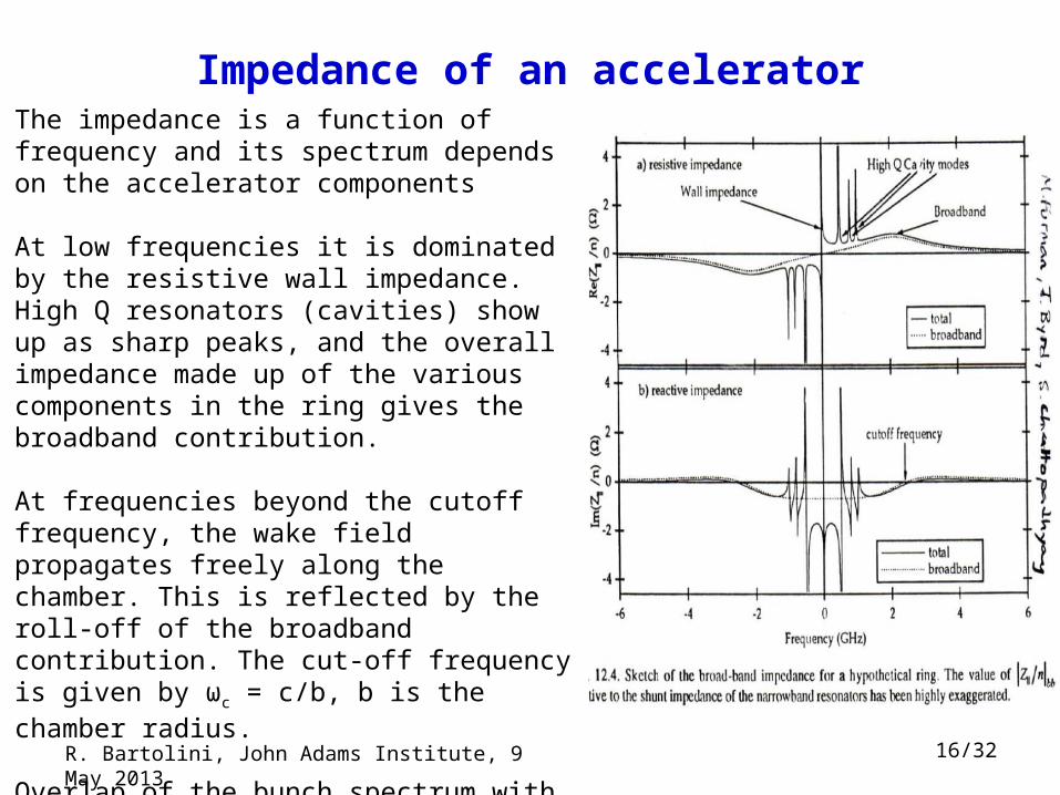
Impedance of an acceleratorThe impedance is a function of frequency and its spectrum depends on the accelerator components
At low frequencies it is dominated by the resistive wall impedance. High Q resonators (cavities) show up as sharp peaks, and the overall impedance made up of the various components in the ring gives the broadband contribution.
At frequencies beyond the cutoff frequency, the wake field propagates freely along the chamber. This is reflected by the roll-off of the broadband contribution. The cut-off frequency is given by ωc = c/b, b is the chamber radius.
Overlap of the bunch spectrum with the impedance of the machine generate instabilities
R. Bartolini, John Adams Institute, 9 May 2013
17/32
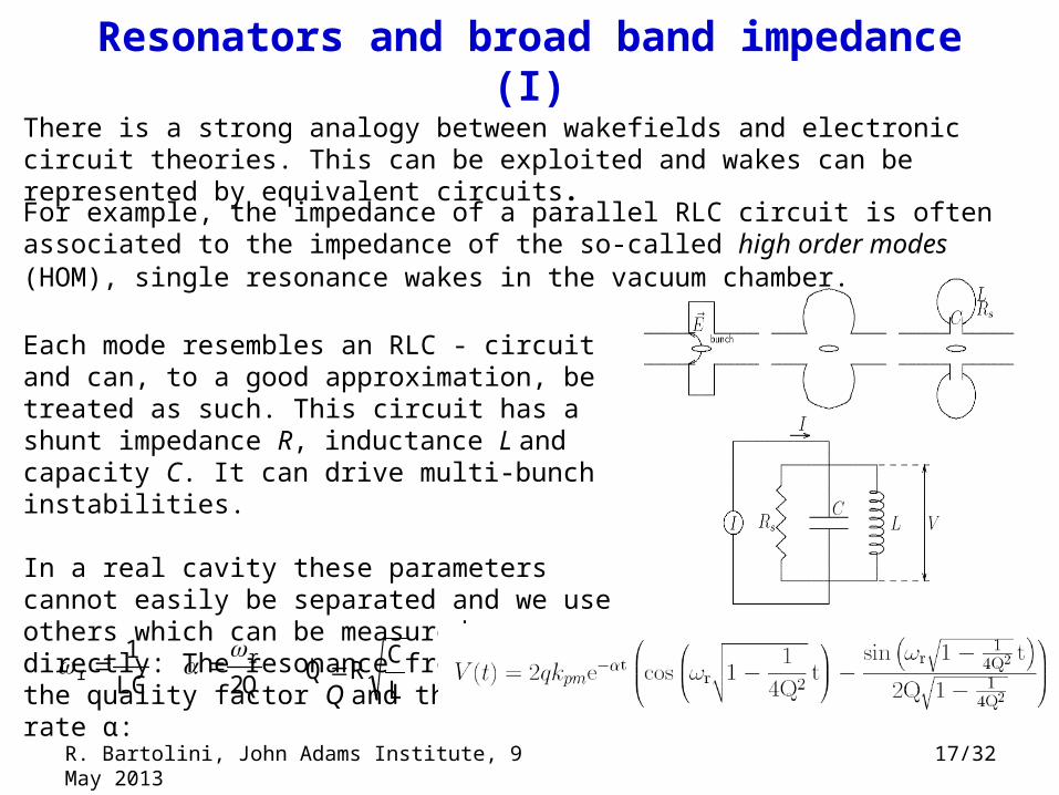
Resonators and broad band impedance (I)
Each mode resembles an RLC - circuit and can, to a good approximation, be treated as such. This circuit has a shunt impedance R, inductance L and capacity C. It can drive multi-bunch instabilities.
In a real cavity these parameters cannot easily be separated and we use others which can be measured directly: The resonance frequency ωr, the quality factor Q and the damping rate α:
LC
1r
L
CRQ
Q2r
There is a strong analogy between wakefields and electronic circuit theories. This can be exploited and wakes can be represented by equivalent circuits.
For example, the impedance of a parallel RLC circuit is often associated to the impedance of the so-called high order modes (HOM), single resonance wakes in the vacuum chamber.
R. Bartolini, John Adams Institute, 9 May 2013
18/33
Resonators and broad-band impedance (II)
r
r||
iQ1
R)(Z
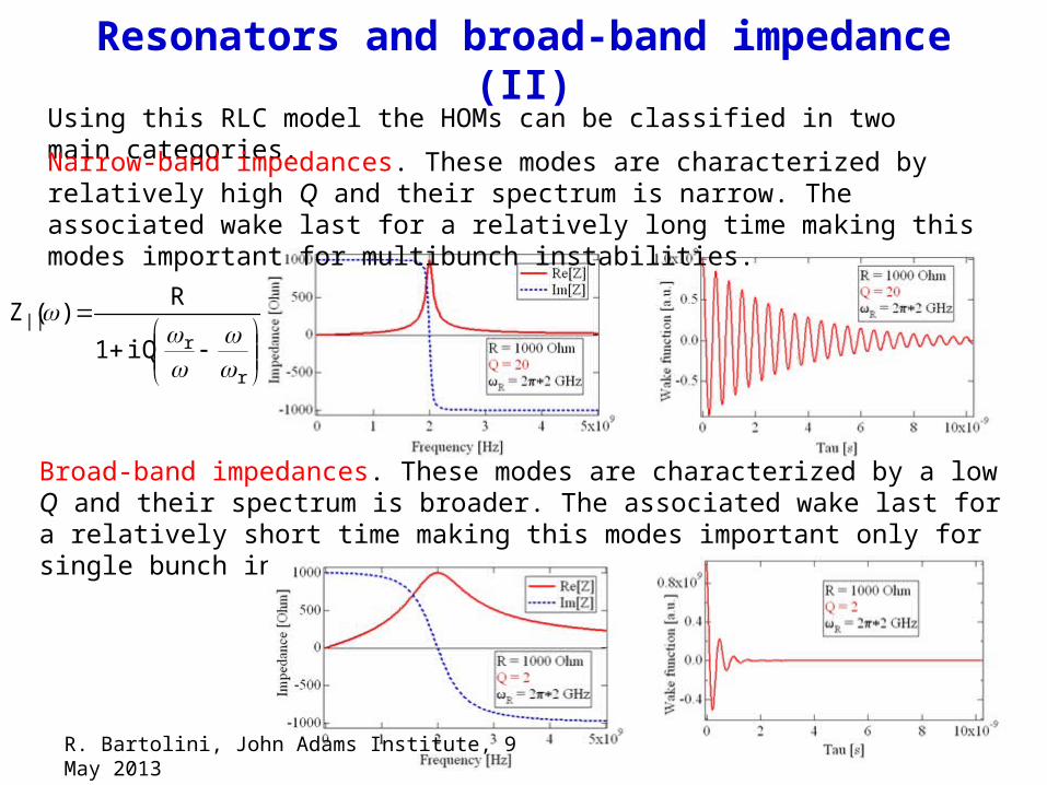
Using this RLC model the HOMs can be classified in two main categories.
Narrow-band impedances. These modes are characterized by relatively high Q and their spectrum is narrow. The associated wake last for a relatively long time making this modes important for multibunch instabilities.
Broad-band impedances. These modes are characterized by a low Q and their spectrum is broader. The associated wake last for a relatively short time making this modes important only for single bunch instabilities.
R. Bartolini, John Adams Institute, 9 May 2013
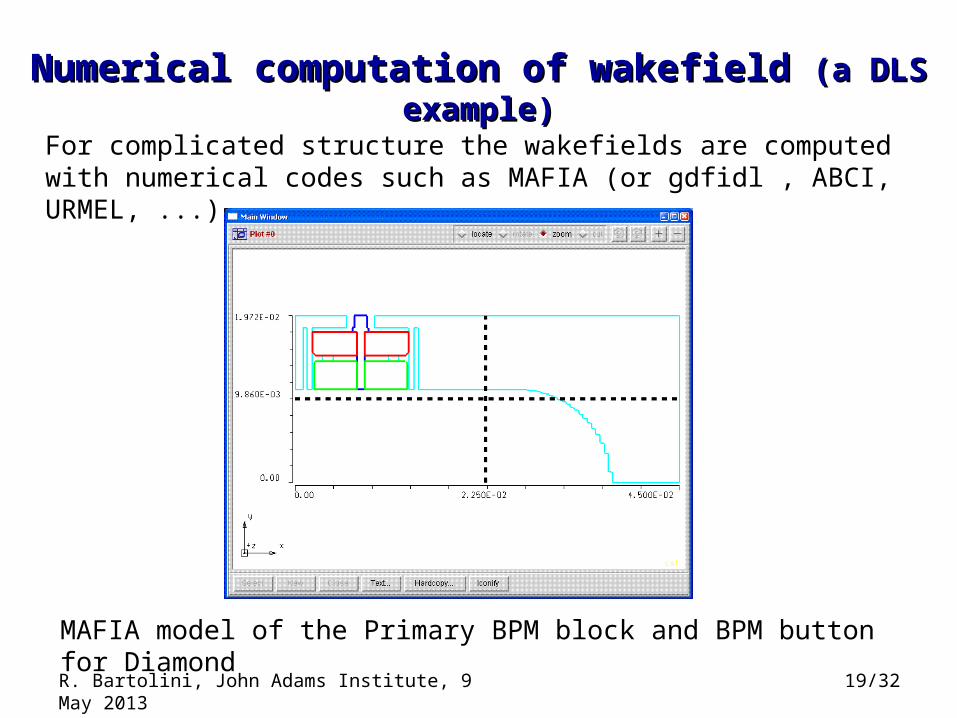
Numerical computation of wakefield Numerical computation of wakefield (a DLS example)(a DLS example)
For complicated structure the wakefields are computed with numerical codes such as MAFIA (or gdfidl , ABCI, URMEL, ...)
MAFIA model of the Primary BPM block and BPM button for Diamond
19/32R. Bartolini, John Adams Institute, 9 May 2013
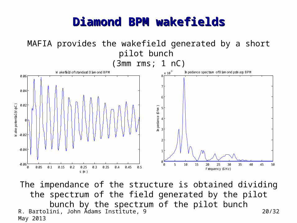
MAFIA provides the wakefield generated by a short pilot bunch (3mm rms; 1 nC)
0 5 10 15 20 25 30 35 40 45 500
1
2
3
4
5
6
7
8x 10
-3 Impedance spectrum of Diamond primary BPM
Frequency (GHz)
Impe
danc
e (O
hm)
0 0.05 0.1 0.15 0.2 0.25 0.3 0.35 0.4 0.45 0.5-0.06
-0.04
-0.02
0
0.02
0.04
0.06
s (m)
Wak
e po
tent
ial (
V/p
C)
Wakefield of standard Diamond BPM
Diamond BPM wakefieldsDiamond BPM wakefields
The impendance of the structure is obtained dividing the spectrum of the field generated by the pilot bunch by the spectrum of the pilot bunch
20/32R. Bartolini, John Adams Institute, 9 May 2013
Impedance databaseImpedance database
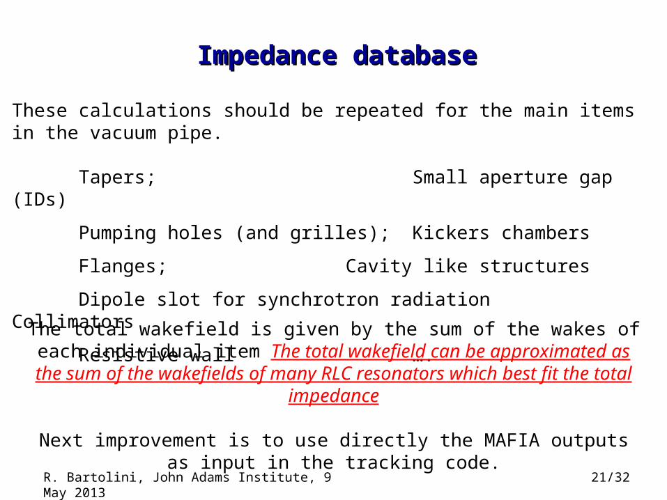
These calculations should be repeated for the main items in the vacuum pipe.
Tapers; Small aperture gap (IDs)
Pumping holes (and grilles); Kickers chambers
Flanges; Cavity like structures
Dipole slot for synchrotron radiation Collimators
Resistive wall ….
The total wakefield is given by the sum of the wakes of each individual item The total wakefield can be approximated as the sum of the wakefields of
many RLC resonators which best fit the total impedance
Next improvement is to use directly the MAFIA outputs as input in the tracking code.
21/32R. Bartolini, John Adams Institute, 9 May 2013
Equation of motion (I)Equation of motion (I)
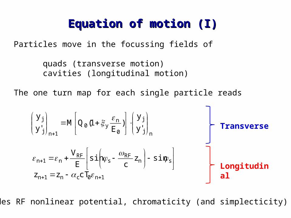
Particles move in the focussing fields of
quads (transverse motion)cavities (longitudinal motion)
The one turn map for each single particle reads
sn
RFs
RFn1n sinz
csin
E
V
1n0cn1n cTzz
nj
j
0
ny0
1nj
j
'y
y)
E1(QM
'y
y
Transverse
Longitudinal
Includes RF nonlinear potential, chromaticity (and simplecticity)
Equation of motion (II)Equation of motion (II)
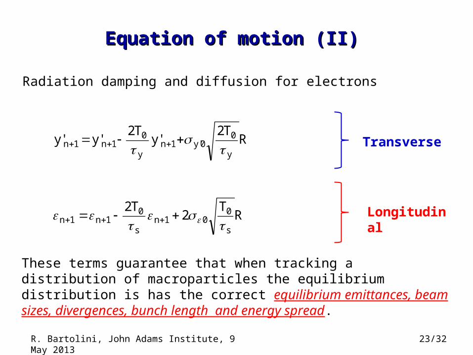
Radiation damping and diffusion for electrons
Transverse
Longitudinal
RT2
'yT2
'y'yy
00'y1n
y
01n1n
RT
2T2
s
001n
s
01n1n
These terms guarantee that when tracking a distribution of macroparticles the equilibrium distribution is has the correct equilibrium emittances, beam sizes, divergences, bunch length and energy spread.
23/32R. Bartolini, John Adams Institute, 9 May 2013
Equation of motion (II)Equation of motion (II)
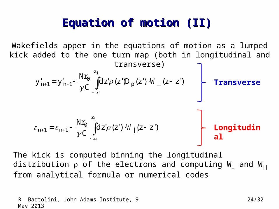
Wakefields apper in the equations of motion as a lumped kick added to the one turn map (both in longitudinal and transverse)
Transverse
Longitudinal
iz
||0
1n1n )'zz(W)'z('dzC
Nr
iz
p0
1n1n )'zz(W)'z(D)'z('dzC
Nr'y'y
The kick is computed binning the longitudinal distribution of the electrons and computing W and W|| from analytical formula or numerical codes
24/32R. Bartolini, John Adams Institute, 9 May 2013
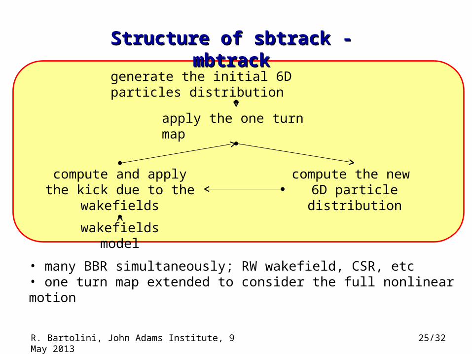
Structure of sbtrack - mbtrackStructure of sbtrack - mbtrack
generate the initial 6D particles distribution
apply the one turn map
compute the new 6D particle distribution
compute and apply the kick due to the wakefields
wakefields model
• many BBR simultaneously; RW wakefield, CSR, etc• one turn map extended to consider the full nonlinear motion
25/32R. Bartolini, John Adams Institute, 9 May 2013
26/32
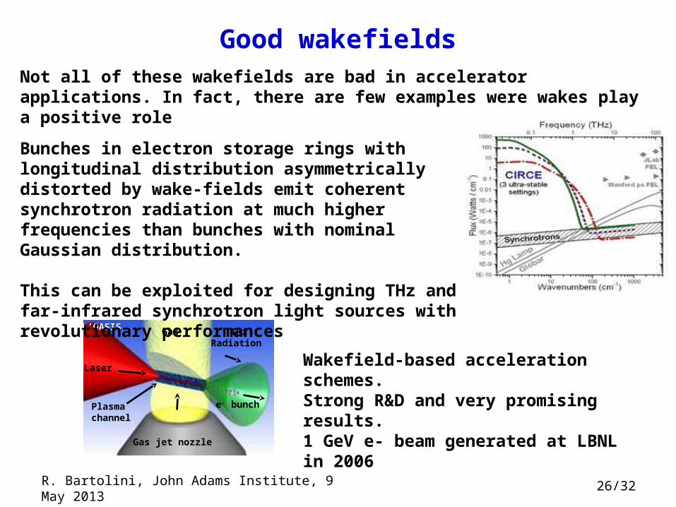
Good wakefieldsNot all of these wakefields are bad in accelerator applications. In fact, there are few examples were wakes play a positive role
Laser
Gas
Gas jet nozzle
e- bunch Plasmachannel
THzRadiation
L’OASISL’OASIS
Wakefield-based acceleration schemes.Strong R&D and very promising results.1 GeV e- beam generated at LBNL in 2006
Bunches in electron storage rings with longitudinal distribution asymmetrically distorted by wake-fields emit coherent synchrotron radiation at much higher frequencies than bunches with nominal Gaussian distribution.
This can be exploited for designing THz and far-infrared synchrotron light sources with revolutionary performances
R. Bartolini, John Adams Institute, 9 May 2013
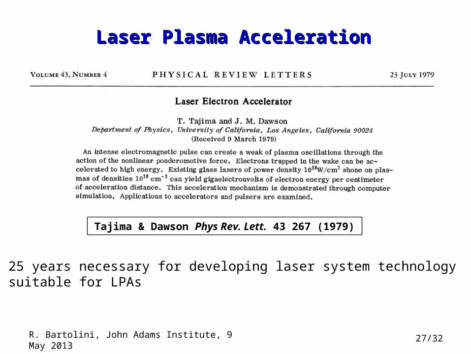
Laser Plasma AccelerationLaser Plasma Acceleration
Tajima & Dawson Phys Rev. Lett. 43 267 (1979)
25 years necessary for developing laser system technology suitable for LPAs
R. Bartolini, John Adams Institute, 9 May 2013 27/32
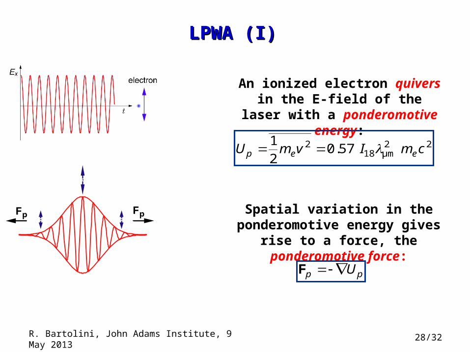
LPWA (I)LPWA (I)
An ionized electron quivers in the E-field of the laser with a
ponderomotive energy:
2 2 218 μm
10.57
2p e eU m v I m c
Spatial variation in the ponderomotive energy gives rise to a
force, the ponderomotive force:
p pU F
FpFp
R. Bartolini, John Adams Institute, 9 May 2013 28/32
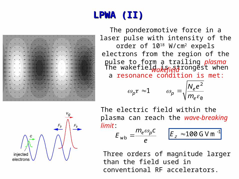
LPWA (II)LPWA (II)
-1100 GVmzE wb
e pm cE
e
Three orders of magnitude larger than the field used in conventional RF accelerators.
The electric field within the plasma can reach the wave-breaking limit:
The wakefield is strongest when a resonance condition is met:
1p
2
0
ep
e
N e
m
The ponderomotive force in a laser pulse with intensity of the order of 1018 W/cm2
expels electrons from the region of the pulse to form a trailing plasma wakefield
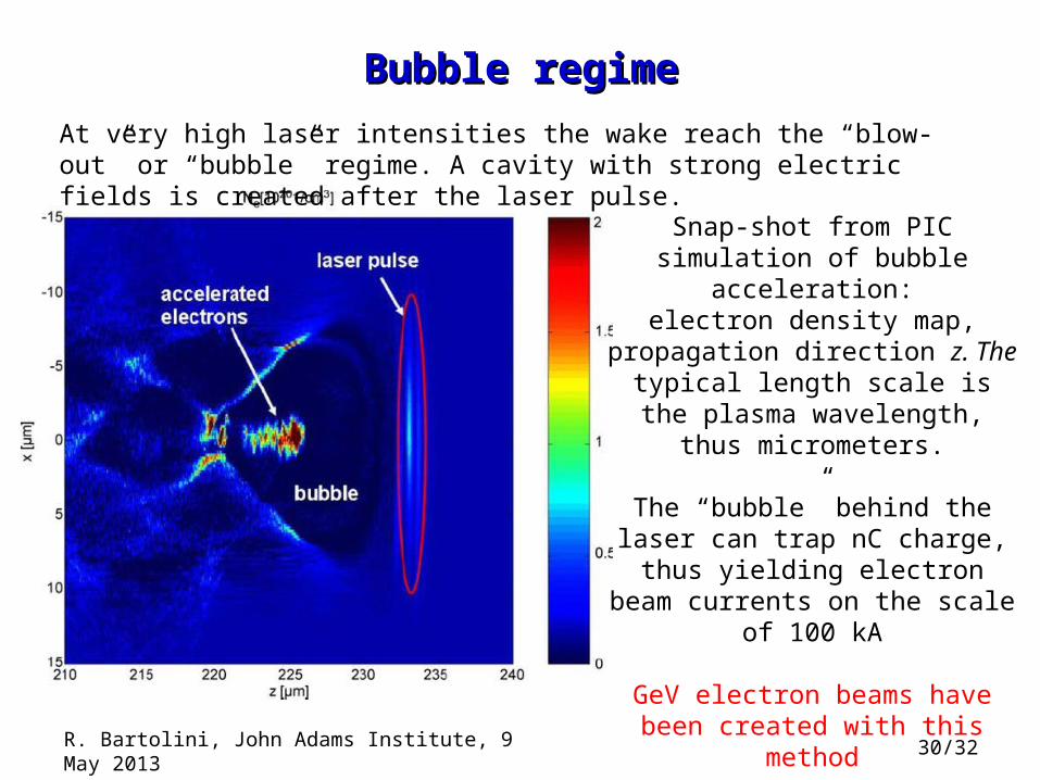
Bubble regimeBubble regime
Snap-shot from PIC simulation of bubble acceleration:
electron density map, propagation direction z. The
typical length scale is the plasma wavelength, thus micrometers.
The “bubble” behind the laser can trap nC charge,
thus yielding electron beam currents on the scale of 100 kA
GeV electron beams have been created with this method
At very high laser intensities the wake reach the “blow-out” or “bubble” regime. A cavity with strong electric fields is created after the laser pulse.
R. Bartolini, John Adams Institute, 9 May 2013 30/32
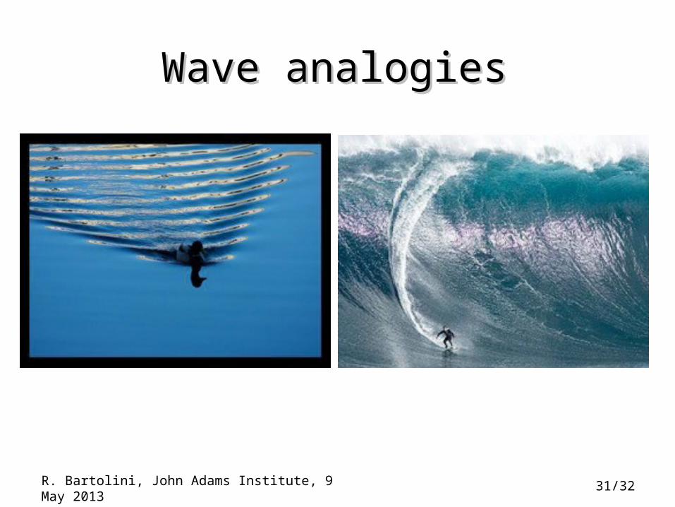
Wave analogiesWave analogies
R. Bartolini, John Adams Institute, 9 May 2013 31/32
32/32
Bibliography
Wakefields
J. D. Jackson, Classical Electrodynamics, John Wiley & sons.
A. Chao, Physics of collective beam instabilities in High energy Accelerators, John Wiley & Sons
Laser Plasma Wakefield Accelerators
E.Esarey, IEEE Trans. Plasma, 24, 232, (1996)
W. Leemans et al., Phil. Trans. R. Soc. A 2006 364, 585-600
R. Bartolini, John Adams Institute, 9 May 2013


![[Syllabus] JTO LICE 2016 - Revised Scheme and Syllabus](https://img.pdfslide.us/doc/110x75/56d6bcce1a28ab30168b8ae8/syllabus-jto-lice-2016-revised-scheme-and-syllabus.jpg)