Embed Size (px)
Citation preview
IS 13947 ( Part 1 ) : 1993IEC Pub 947-l ( 1988 )
Indian Standard
SPECIFICATIONFORLOW-VOLTAGESWITCHGEARANDCONTROLGEAR
PART 1 GENERAL RULES
NATIONAL FOREWORD
This Indian Standard ( Part 1 ) which is identical with IEC Pub 947-l ( 1988 ) ‘Low-voltage switch-gear and controlgear - Part 1 : General rules’, issued by the International ElectrotechnicalCommission ( IEC ) is being brought out to align the requirements for low-voltage switchgearitems in line with the corresponding requirements at the IEC level. With this standard, efforts havebeen undertaken to align all product standards in this field with the relevant IEC publications.
This standard is intended to serve as a guide for general requirements of all switchgear andcontrolgear equipment for voltages not exceeding 1 000 V ac or 1 200 V dc. Individual parts of thisstandard would cover different switchgear and controlgear items ( wherein modifications to thegeneral requirements specified in this standard, wherever necessary, will also be included ).
The text of the IEC standard has been considered and approved by ET 07, Low Voltage Switch-gear and Controlgear Sectional Committee of BlS as suitable for publication as Indian Standard,superseding the contents of IS 4237 which covered general requirements for all types of LTswitchgear equipment.
CROSS REFERENCES
In this Indian Standard the following international standards are referred to. Read in theirrespective place the following:
International Stanciard ( IEC ) Indian Standard
50 ( 151 ) ( 1978 )50 (441 ) ( 1984)50 ( 604 ) ( 1987 )5$ ( 828 ) ( 1982 )
71-l ( 1978 )73 ( 1984 )85 ( 1984 )99-1 ( 1970)112 ( 1979 )144 ( 1963 )216269-l ( 1986 )
1
;$4 $4’3988 )
417‘( -1973 )439-l445 ( 1973 )447 ( 1974 )529 ( 1976 )617-7 ( 1983 )664 ( 1980 )664 A ( 1981 )
IS 1885 ( Part 57 )IS 1885 ( Part 17 )
1s 732IS 2071IS 2185NilIS 1271:SS g2i ( Part 1 )
IS 11182
IS 9224
SP 30NilIS 8623IS 11353IS 7118IS 12063IS 12032 ( Part 7 )SP 89
1
IS 13947 ( Part 1 ) : 1993IEC Pub 947-l ( 1988 )
All these Indian Standards are technically equivalent to the IEC publications referred.
In the case of IEC Pub 50 ( 604 ), 73 and 417, the Technical Committee responsible for the prepa-ration of this standard has decided that they are acceptable for use in conjunction with thisstandard.
NATIONAL ANNEX
Keeping in view the application of this standard in Indian conditions, the Technical Committeeresponsible for this standard has felt the need to select from out of the ratings/ranges those bestsuited for Indian conditions and provide elaboration interpretations where felt necessary. Forconvenience of the users and to facilitate comparison, the aspects to be taken note of, forclaiming conformity to this standard under Indian conditions are summarized in the form of aNational Annex.
The text of this standard shall be read in conjunction with this annex which is an integral partof it.
3i
IS 13947 (Part 1) : 1?393lEC Pub 947 - 1 ( 1988 )
CONTENTS
Page
2.
3.
4.
5.’
6.
7.
General . . . . . . . . . . . . . . . . . . . . . . . . . . . . . . . . . . . . . . . . . . . . . . . . . . . . . . . . .1.1 scope . . . . . . . . . . . . . . . . . . . . . . . . . . . . . . . . . . . . . . . . . . . . . . . . . . . . . . .1.2 Object . . . . . . . . . . . . . . . . . . . . . . . . . . . . . . . . . . . . . . . . . . . . . . . . . . . . . . .
Definitions . . . . . . . . . . . . . . . . . . . . . . . . . . . . . . . . . . . . . . . . . . . . . . . . . . . . . . .
2.12.22.32.42.52.6
Alphabetical index of definitionsGeneral terms .Switching devices . .Parts of switching devices .Operation of switching devicesCharacter is t ic quant i t ies . .Tests ,
. .... .
.
. .
.
. ..
Classification . . . . . . . . . .
Characteristics . . . . .
4.14.24.34.44.54.64.74.84.9
Alphabetical list of characteristics (whether rated or not) and symbolsGeneral ....................................Type of equipment ..............................Rated and limiting values for the main circuit ..............Utilization category .............................Control circuits ................................Auxiliary circuits ...............................Relays and releases .............................Co-ordination with short-circuit protective devices (SCPD) .......Switching overvoltages ............................
. .
. .
. .
.
. .
.
. .
.
.
. .
Product information ..................................................5.1 Nature of information ..............................................5.2 Marking . . . . . . . . . . . . . . . . . . . . . . . . . . . . . . . . . . . . . . . . . . . . . . . . . . . . . .5.3 Instructions for installation, operation and maintenance ...........................
Normal service, mounting and transport conditions ................................6.1 Normal service conditions ............................................6.2 Conditions during transport and storage ...................................6.3 Mounting . . . . . . . . . . . . . . . . . . . . . . . . . . . . . . . . . . . . . . . . . . . . . . . . . . . . .
Constructional and performance requirements ....................................7.1 Constructional requirements ..........................................
7.1.1 Materials _, .................................7.1.2 Current-carrying parts and their connections ..............7.1.3 Clearances and creepage distances ....................7.1.4 Actuator ...................................7.1.5 Indication of the contact position ....................7.1.6 Additional safety requirements for equipment suitable for isolation7.1.7 Terminals. ..................................7.1.8 Additional requirements for equipment provided with a neutral pole7.1.9 Provisions for protective earthing ....................7.1.10 Enclosures for equipment ..........................7.1.11 Degrees of protection of enclosed equipment ..............
.
. .
. .
. .
.
..
. .
. .
. .
.
. .
. .
. .
. .
.
. .
.7.2 Performance reauirements . . . . . . . . . . . . .
7.2.17.2.27.2.37.2.4
Operating conditions ...........................................Temperature-rise .............................................Dielectric properties ...........................................Ability to make, carry and break currents under no-load, normal load and overload conditions
7.2.5 Ability to make, carry and break short-circuit currents .......................7.2.6 Switching overvoltages ..........................................7.2.7 Leakage currents of equipment suitable for isolation .........................
555
66
1012
:t2027
27
28282829
;:
z
E363636373738
z;40
40
$
ii40414142
ifi4545
:;
$;:51
5s:53
c
3
Is 13947 (Part 1) : 1993IEC Pub 947 - 1 ( 1988 )
Clause
8 . T e s t s . . . . . . . . . . . . . . . . . . . . . . . . . . . . . . . . . . . . . . . . . . . . . . . . . . . . . . . . . . .
8.1 Kinds of test ...................................................8.1.1 Genera l ..................................................8.1.2 Type tests .................................................8.1.3 Routine tests ...............................................8.1.4 Sampling tests ..............................................
8.2 Compliance with constructional requirements .................................8.2.1 Materials .................................................8.2.2 Equipment ................................................8.2.3 Enclosures for equipment ........................................8.2.4 Mechanical properties of terminals ...................................8.2.5 Verification of strength of actuating system and position indicator of equipment suitable for
isolation . . . . . . . . . . . . . . . . . . . . . . . . . . . . . . . . . . . . . . . . . . . . . . . . . .8.3 Performance ...................................................
8.3.1 Test sequences ..............................................8.3.2 General test conditions .........................................8.3.3 Performance under no load, normal load and overload conditions .................8.3.4 Performance under short-circuit conditions ..............................
FIGURE I . . . . . . . . . . . . . . . . . . . . . . . . . . . . . . . . . . . . . . . . . . . . . . . . . . . . . . . . . .FKLJRE~ . . . . . . . . . . . . . . . . . . . . . . . . . . . . . . . . . . . . . . . . . . . . . . . . . . . . . . . . . .FI(;uRES3tol5 . . . . . . . . . . . . . . . . . . . . . . . . . . . . . . . . . . . . . . . . . . . . . . . . . . . . . . .
TABLE
I.I I .
111.IV.
v .VI.
VII .V I I I .
IX.X.
X l .X I I .
X I I I .X IV .x v .
XVI .
Standard cross-sections of round copper conductors .............................Tempcraturc-rise limits of terminals .......................................Temperature-rise limits of accessible parts ....................................Tightcnmg, torques for the verification of the mechanical strength of screw-type terminals .......Test valuer for flcxion and pull-out tests for round copper conductors ...................Test values for pull-out test for flat copper conductors ............................Maximum conductor cross-sections and corresponding gauges ........................Tolerances on test quantities ..........................................Test copper conductors for test currents up to 400 A inclusive ........................Test copper conductors for test currents above 400 A and up to 800 A inclusive ..............Test copper bars for test currents above 400 A and up to 3 150 A inclusive ................Dielectric withstand vt111.1~:‘~ for impulse, power frcqucncy and d.c. tests ..................
Minimum clearances in air ............................................Test voltages across the open contacts of equipment suitable for isolation .................Minimum crccpagc distances ...........................................Values of power-factors and time-constants corresponding to test currents. and ratio II between peak andr.m.s. values of current ..............................................
AlwiNI)IX A Examples o f utilizration catcgorics f o r low-voltage s w i t c h g e a r a n d c o n t r o l g e a rAI’I’I:NI~IX H Suitability of the equipment when conditions for operation in scrvrce differ from the normal
c o n d i t i o n s
97
AIWNDIX C’ Dcgrccs of protection of cncloscd cquipmcntAl’l’liNI>IX D Examplcr o f terminals _I./iI’I’I:NI>IX E - Description o f a method f o r a d j u s t i n g t h e l o a d c i r c u i tAIJI+NI)IX F Dctcrmination of short-circuit power-factor or timeconstantAl’l’l:NIm c; Measurement o f c r e c p a g e distances a n d c l e a r a n c e sAPWNINX H --- Correlation bctwccn the nominal voltage of the supply system and the rated impulse withstand
;i117123126128
vollagc o f cquipmcnt 134AIJWNIXX J ~. Items subject t o agrccmcnt h c t w c c n manufacturer a n d user 137
6161
66:
!J:
ss:84
43
4’:
2s”596062
:::6871
727273
79
Is 13947 (Part 1) : 1993IEC Pub 947 - 1 ( 1988 )
I. General
The purpose of this standard is to harmonize as far as practicable all rules and require-ments of a general nature applicable to low-voltage switchgear and controlgear in order toobtain uniformity of requirements and tests throughout the corresponding range of equip-ment and to avoid the need for testing to different standards.
All those parts of the various equipment standards which can be considered as generalhave therefore been gathered in this standard together with specific subjects of wide interestand application, e.g. temperature-rise, dielectric properties, etc.
For each type of low-voltage switchgear and comrolgear, only two main documents arenecessary to determine all requirements and tests:I) this basic standard, referred to as “Part 1” in the specific standards covering the various
types of low-voltage switchgear and controlgear;‘2) the relevant equipment standard hereinafter referred to as the “relevant product stan-
dard” or “product standard”.For a general rule to apply to a specific product standard, it shall be explicity referred to
by the latter, by quoting the relevant clause or sub-clause number of this standard followedby “Part 1” e.g. “Sub-clause 7.2.3 of Part 1”.
A specific product standard may not require, and hence may omit, a general rule (as beingnot applicable), or it may add to it (if deemed inadequate in the particular case), but it maynot deviate from it, unless there is a substantial technical justification.
Nofe. The product standards due to be part of the series of I E C standards covering low-voltage switchgear andcontrolgear are:
947-2 : Part 2 : Circuit-breakers.947-3 : Part 3 : Switches, disconnectors, switch-disconnectors and fuse combination units.947-4: Part 4: Contactors and motor-starters.947-5: Part 5: Control-circuit devices and switching elements.947-6: Part 6: Multiple function switching devices.947-7: Part 7: Ancillary equipment.
1.1 Scope
This standard applies, when required by the relevant product standard, to switchgear andcontrolgear hereinafter referred to as “equipment” and intended to be connected to circuits,the rated voltage of which does not exceed 1 000 V a.c. or 1 500 V d.c.
It does not apply to low-voltage switchgear and controlgear assemblies which are dealtwith in I E C Publication 439.Note. - In certain clauses or sub-clauses of this standard, the equipment covered by this standard is also referred
to as “device” to be consistent with the text of such clauses or sub-clauses.
1.2 Object
The object of this standard is to state those general rules and requirements which arecommon to low-voltage equipment as defined in Sub-clause 1.1, including for example: ’
5
IS 13947 (Part 1) : 1993IEC Pub 947 - 1 ( 1988 )
- definitions,- characteristics,- information supplied with the equipment,- normal service, mounting and transport conditions,- constructional and performance requirements,- verification of characteristics and performance.
2. Definitions
Nore. - Most of the definitions listed in this clause are taken unchanged from the IEV (I E C Publication 50).When this is the case, the IEV reference is given in brackets with the title (the first group of 3 figuresindicates the IEV chapter reference).
When an IEV definition is amended, the IEV reference is not indicated with the title, but in anexplanatory note.
Alphabetical index of definitions
Note. - The alphabetical list of ratings, characteristics and symbols is given in Clause 4.
“a” contact ........................Actuating force (moment) ...............Actuating system (of a mechanical switching device)Actuator .........................Ambient air temperature ................Anti-pumping device ..................Applied voltage (for a switching device) .......Arcing contact ......................Arcing time (of a multipole switching device) ....Arcing time (of a pole or a fuse) ...........Automatic control .....................Auxiliary circuit (of a switching device) ........Auxiliary contact ....................Auxiliary switch (of a mechanical switching device)
B
“b” contact . . . . . . . .B a c k - u p p r o t e c t i o nBreak contact ~ . .Breaking capacity (of a switching device or a fuse)Breaking current (of a switching device or a fuse)Break time . .
A
.
.
. .
Circuit-breaker . .C l a m p i n g u n i tClearance . .C l e a r a n c e b e t w e e n o p e n c o n t a c t s ( g a p )
Ciedrance between pOks . ,Clearance to earth .Closed position (of a mechanical switching device) . .Closing operation (of a mechanical switching device)C l o s i n g t i m eComparative tracking index (CTI) YConditional short-circuit current (of a circuit or a switching device)C o n d u c t i v e p a r tC o n t a c t ( o f a m e c h a n i c a l s w i t c h i n g d e v i c e )C o n t a c t p i e c e .
.
.
Rrfercnce
2.3.122.4.172.3.162.3.172.1.92.3.202.5.322.3.82.5.412.5.402.4.52.3.42.3.102.3. I I
2.3.132.5.242.3.132.5.122.5.1 I2.5.42
2.2.1123.252.5.462.5.492.5.472.5.482.4.202.4.X2.5.442.5.652.5.292.1.102.3.52.3.6
G
Is 13947 (Part 1) : 1993IEC Pub 947 - 1 ( 1988 )
Contactor (mechanical) ...........................Contactor relay ...............................Control circuit (of a switching device) ..................Control circuit device ............................Control contact ...............................Controlgear ..................................Control switch (for control and auxiliary circuits) ............Conventional non-tripping current (of an over-current relay or release)Conventional tripping current (of an over-current relay or release) . .Co-ordination of insulation .........................Creepage distance ..............................Critical load current .............................Critical short-circuit current ........................Current setting (of an over-current or overload relay or release) ....Current setting range (of an over-current or overload relay or release)Cut-off current ................................Cut-off (current) characteristic .......................
D
D.C. steady-state recovery voltage ..................Definite time-delay over-current relay or release ..........Dependent manual operation (of a mechanical switching device)D pendent power operation (of a mechanical switching device)d
.erect over-current relay or release .................
Disconnector ..............................Discrimination - see Over-current discrimination
E
Electric shock .............................Enclosure ................................Exposed conductive part .......................Extraneous conductive part ......................
. .
. .
2.2.122.2.142.3.32.2.162.3.92.1.32.2.172.5.302.5.312.5.612.5.512.5.162.5.172.4.372.4.382.5192.5.21
2.5.362.4.262.4.122.4.132.4.282.2.8
2.1.202.1.162.1.112.1.12
F
Functional overvoltage . . .F u s e , . _‘............................
Fuse-combination unit . . . .F u s e - e l e m e n tF u s e - l i n k
2.5.54.32.2.42.2.72.2.62.2.5
H
Homogeneous (uniform) field . . . . . . . . . . . . . . . . . . . 2.5.62
I
Impulse withstand voltage . . .Independent manual operation (of a mechanical switching device)Independent power operation (of a mechanical switching device)I n d i c a t o r l i g h tI n d i r e c t o v e r - c u r r e n t r e l a y o r r e l e a s e .I n h o m o g e n e o u s ( n o n - u n i f o r m ) f i e l dI n s t a n t a n e o u s r e l a y o r r e l e a s eI n t e g r a l e n c l o s u r eI n t e r l o c k i n g d e v i c eInverse time-delay over-current relay or releaseIsolating distance (of a pole of a mechanical switching device)I s o l a t i o n ( i s o l a t i n g f u n c t i o n )
J
2.5.552.4.152.4.162.3.192.4.292.5.632.4.242.1.172.3.212.4.272.5.502.1.19
J o u l e i n t e g r a l (Pt) 2.5.18
L
Let-through current .......................... 2 . 5 . 1 9Let-through (current) characteristic ................. 2 . 5 . 2 1Lightning overvoltage ......................... 2 . 5 . 5 4 . 2
7
I!S13947(Part1):1993IEOPub947-l(1988)
Limiting value .........................Live part ............................Local control ...........................
M
Magnetic overload relay or release .............Main circuit (of a switching device) .............Main contact ..........................Make-break time .......................Make contact .........................Make time ...........................Making capacity (of a switching device) ..........Manual control ........................Maximum prospective peak current (of an a.c. circuit) .Mechanical switching device .................Micro-environment (of a clearance or creepage distance) .
N
Neutral conductor (symbol N) ................Nominal value . . . . . . . . . . . . . . . . . . . . . . . . .
0
. .
.. .
. .
. .
.
.
RR a t e d v a l u e 2.5.3Rating ., .., . . . . . . ., . . . . . . . . . . . . . 2.5.4R e c o v e r y v o l t a g e 2.5.33Relay (electrical) . 2.3.14Release (of a mechanical switching device) . 2.3.15
O p e n p o s i t i o n ( o f a m e c h a n i c a l s w i t c h i n g d e v i c e )Opening operation (of a mechanical switching device) ...........Opening time (of a mechanical switching device) .............Operating current (of an over-current relay or release) ..........Operating cycle (of a mechanical switching device) ............Operating sequence (of a mechanical switching device) ..........Operation (of a mechanical switching device) ...............Over-current ..................................Over-current discrimination ..........................Over-current protective co-ordination of over-current protective devicesOver-current relay or release ..........................Overload ....................................Overload current ................................Overload relay or release ...........................Overvoltage category (of a circuit or within an electrical system) ....
PPeak arc voltage (of a mechanical switching device) .................Peak withstand current .................................Pilot switch .......................................Pole of a switching device ................. j .............Pollution .........................................Pollution degree (of environmental conditions) ....................Position indicating device ................................Positively driven operation ...............................Positive opening operation (of a mechanical switching device) ...........Power-frequency recovery voltage ...........................Power-frequency withstand voltage ..........................Prepared conductor ...................................Prospective breaking current (for a pole of a switching device or a fuse) .....Prospective current (of a circuit and with respect to a switching device or a fuse)Prospective making current (for a pole of a switching device) ...........Prospective peak current ................................Prospective symmetrical current (of an a.c. circuit) .................Prospective transient recovery voltage (of a circuit) .................Protective conductor (symbol PE) ...........................Push-button .......................................
Reference
2.5.22.1.132.4.6
2.4.322.3.22.3.125.452.3.122.5.4325.132.4.42.5.82.2.22.5.59
2.1.152.5.1
2.4.212.4.92.5.392.4.362.4.22.4.32.4.12.1.42.5.232.5.222.4.252.1.72.1.82.4.302.5.60
2.5.382.5.282.2.182.3.12.5.572.5.582.3.182.4.112.4.102.5.352.5.562.3.272.5.102.5.52.5.92.5.62.5.72.5.312.1.142.2.19
8
IS 13947 (Part 1) : 1993IEC Pub 947 - 1 ( 1988 )
Reference
Remote control ..........................Restoring force (moment) .....................Reverse current relay or release (d.c. only) ...........Routine test ............................
S
Sampling test ..........................Screw-type terminal ......................Screwless-type terminal ....................Selectivity (see Sub-clause 25.22)Semiconductor contactor (solid state contactor) ......Semiconductor switching device ...............Short-circuit ..........................Short-circuit breaking capacity ... , ............Short-circuit current ......................Short-circuit making capacity ................Short-circuit protective device (SCPD) . . . . . . . . . . .Short-time delay ........................Short-time withstand current .................Shunt release ..........................Special test ...........................Starter .............................Stored energy operation (of a mechanical switching device)Surge arrester .........................Switch (mechanical) ......................Switch-disconnector ......................Switchgear ...........................Switchgear and controlgear ..................Switching device ........................Switching overvoltage ... .................
..........
............ . .
. . . . .
.
. . .
.
T
Take-over current ........................Temporary overvoltage ......................Terminal ..............................Terminal block ...........................Thermal overload relay or release ................Time-current characteristic ....................Tracking ..............................Transient overvoltages ......................Transient recovery voltage (abbrev. TRV) . . . . . . . . . . .
Travel (of a mechanical switching device or a part thereof)Trip-free mechanical switching device ..............Tripping (operation) ........................Type test ..............................
U
U n d e r - v o l t a g e r e l a y o r r e l e a s e .U n p r e p a r e d c o n d u c t o rUtilization category (for a switching device or a fuse)
W
...... 2.4.34
...... 2.3.26
...... 2.1.18
Working voltage . . . . 2.5.52
2.4.72.4.182.4.352.6.2
2.6.32.3.232.3.24
2.2.132.2.32.1.52.5.142.1.62.5.152.2.212.5.262.5.212.4.332.6.42.2.152.4.142.2.222.2.92.2.102.1.22.1.12.2.12.5.54. I
2.5.252.5.532.3.222.2.202.4.312.5.202.5.642.5.542.5.34X4.192.4.232.4.222.6.1
.
9
Is13947(Pert1):1993IECPub947-l(1988)
2.1 General terms
2.1.1 Switchgear and con trolgear (44 I- 11-O 1)A general term covering switching devices and their combination with associated control,
measuring, protective and regulating equipment, also assemblies of such devices and equip-ment with associated interconnections, accessories, enclosures and supporting structures.
2.1.2 Switchgear (441-1 l-02)
A general term covering switching devices and their combination with associated control,measuring, protective and regulating equipment, also assemblies of such devices and equip-ment with associated interconnections, accessories, enclosures and supporting structures,intended in principle for use in connection with generation, transmission, distribution andconversion of electric energy.
2.1.3 Controlgear (441-01-03)
A general term covering switching devices and their combination with associated control,measuring, protective and regulating equipment, also assemblies of such devices and equip-ment with associated interconnections, accessories, enclosures and supporting structures,intended in principle for the control of electric energy consuming equipment.
2.1.4 Over-current (441-I l-06)A current exceeding the rated current.
2.1.5 Short-circuit (151-03-41)
The accidental or intentional connection, by a relatively low resistance or impedance, oftwo or more points in a circuit which are normally at different voltages.
2.1.6 Short-circuit current (44 1 - 1 I-07)
An over-current resulting from a short-circuit due to a fault or an incorrect connection inan electric circuit.
2.1.7 Overload (441-11-08)Operating conditions in an electrically undamaged circuit which cause an ovkr-current.
2.1 .g Overload current
An over-current occurring in an electrically undamaged’ circuit.
2.1.9 Ambient air temperature (441-l 1-13)‘The temperature, determined under prescribed conditions, of the air surrounding the
complete switching device or fuse.Noie. - For switching devices or fuses installed inside an enclosure, it is the temperature of the air outside the
enclosure.
2.1.10 Conductive part (44 1 - 1 l-09)A part which iscapable of conducting current although it may not necessarily be used for
carrying service current.
2.1.11 Exposed con+ctive part (441-11-10)A conductive part which can readily be touched and which is not normally alive, but which
may become alive under fault conditions.Note. - Typical exposed conductive parts are walls of enclosures, operating handles, etc.
10
Is13947(Part1):1993lECPub947-l(1988)
2.1.12 Extraneous conductive part (826-03-03)A conductive part not forming part of the electrical installation and liable to introduce a
potential, generally the earth potential.
2.1. I3 Live part (826-03-01)A conductor or conductive part intended to be energized in normal use, including a neutral
conductor but, by convention, not a PEN conductor.
Note. - This term does not neomsarhy imply a risk of electric shock.
2.1.14 Protective conductor (symbol PE) (826-04-05)A conductor required by some measures for protection against electric shock forelectri-
tally connecting any of the following parts:- exposed conductive parts,- extraneous conductive parts,- main earthing terminal,- earth electrode,- earthed point of the source or artificial neutral.
2.1.15 Neutral conductor (symbol N) (826-O l-03)A conductor connected to the.neutral point of a system and capable of contributing to the
transmission of electrical energy.
Note. - In some cases, the functions of the neutral conductor and the protective conductor may be combinedunder specitied conditions in one and the same conductor referred to as the PEN conductor (SymbolPEN).
2.1.16 EnclosureA part providing a specified degree of protection of equipment against certain external
influences and a specified degree of protection against approach to’or contact with live partsand moving parts.
Note. - This definition is similar to IEV 441-13-01, which applies to assemblies.
2.1.17 Integral enclosureAn enclosure which forms an integral part of the equipment.
2.1.18 Utilization category (for a switching device or a fuse) (441-17-19)A combination of specified requirements related to the conditions in which the switching
device or the fuse fultils its purpose, selected to represent a characteristic group of practicalapplications.Note. - The specified requirements may concern e.g. the values of making capacities (if applicable), breaking
capacities and other characteristics, the associated circuits and the relevant conditions of use andbehaviour.
2.1.19 Isolation (isolating function)Function intended to cut off the supply from all or a discrete section of the installation by
separating the installation or section from every source of electrical energy for reasons ofsafety.
2.1.20 Electric shock (826-03-04)Pathophysiological effect resulting from an electric current passing through a human or
animal body. 2
11
IS 13947 (Part 1) : 1993IEC Pub 947 - 1 ( 1988 )
2.2 Switching devices
2.2.1 Switching device (441-14-01)A device designed to make or break the current in one or more electric circuits.
Note. - A switching device may perform one or both of these operations.
2.2.2 Mechanical switching device (441-14-02)A switching device designed to close and open one or more electric circuits by means of
separable contacts.
Note. - Any mechanical switching device may be designated according lo the medium in which its contacts openand close, e.g.: air, SF,, oil.
2.2.3 Semiconductor switching deviceA switching device designed to make and/or break the current in an electric circuit by
means of the controlled conductivity of a semiconductor.
Note. - This definition differs from IEV 441-14-03 since a semiconductor switching device is also designed forbreaking the current.
2.2.4 Fuse (441-18-01)A device that, by the fusing of one or more of its specifically designed and proportioned
components, opens the circuit in which it is inserted by breaking the current when thisexceeds a given value for a sufficient time. The fuse comprises all the parts that form thecomplete device;
2.2.5 Fuse-link.(441-18-09)The part of a fuse (including the fuse-element(s)) intended to be replaced after the fuse has
operated.
2.2.6 Fuse-element (441-18-08)A part of the fuse-link designed to melt under the action of current exceeding some definite
value for a definite period of time.
2.2.7 Fuse-combination unit (441-14-04)A combihation of a mechanical switching device and one or more fuses in a composite
unit, assembled by the manufacturer or in accordance with his instructions.
2.2.8 DisconnectorA mechanical switching device which, in the open position, complies with the requirements
specified for the isolating function.
Note. - This definition differs from IEV 441-14-05 because the requirements for the isolating function are notbased only on an isolating distance.
2.2.9 Switch (mechanical) (441-14-10)A mechanical switching device capable of making; carrying and breaking currents under
normal circuit conditions which may include specified operating overload conditions andalso carrying for a specified time currents under specified abnormal circuit conditions such asthose of short-circuit.
Note. - A switch may be capable of making but not breaking short-circuit currents.
2.2.10 Switch-disconnector (441-14-12)A switch which, in the open position, satisfies the isolating requirements specified for a
disconnector.
12
Is 13947 (Part 1) 1993:IEC Pub 947 - 1 ( 1988 )
2.2.11 Circuit-breaker (441-14-20)
A mechanical switching device, capable of making, carrying and breaking currents undernormal circuit conditions and also making, carrying for a specified time and breakingcurrents under specified abnormal circuit conditions such as those of short-circuit.
2.2.12 Contactor (mechanical) (441-14-33)A mechanical switching device having only one position of rest, operated otherwise than
by hand, capable of making, carrying and breaking currents under normal circuit conditionsincluding operating overload conditions.
Note. - Contactors may be designated according to the method by which the force for closing the main contacts isprovided.
2.2.13 Semiconductor contactor (solid state contactor)A device which performs the function of a contactor by utilizing a semiconductor
switching device.
Note. - A semiconductor contactor may also contain mechanical switching devices.
2.2.14 Contactor relay (441-14-35)
A contactor used as a control switch.
2.2.15 Starter (441- 14-38)
The combination of all the switching m&ins necessary to start and stop a motor, incdmbination with suitable overload protection.
Nofr. - Starters may be designated according to the method by which the force for closing the main contacts isprovided.
2.2.16 Control circuit device
An electrical device, intended for the controlling, signalling, interlocking, etc. of switch-gear and controlgear.
.Votc. -- Control circuit devices may include associated devices dealt with in other standards, such as instruments,potentiometers. relays, in so far as such associated devices are used for the purposes specified.
2.2.17 Control switch (for control and auxiliary circuits) (441-14-46)
A mechanical switching device which serves the purpose of controlling the operation of.switchgear or controlgear, including signalling, electrical interlocking, etc.
Note,. -- A control switch consists of one or more contact elements with a common actuating system.
2.2.18 Pilot switch (441-14-48)A non-manual control switch actuated in response to specified conditions of an actuating
quantity.
Nore. -- The actuating quantity may be pressure, temperature, velocity, liquid level. elapsed time, etc.
2.2.19 Push-button (441-14-53)
A control switch having an actuator intended to be operated by force exerted by a part ofthe human body, usually the finger or palm of the hand, and having stored energy (spring)return.
2.2.20 Terminul block
An insulating part carrying one or more mutually insulated terminal assemblies andintended to be fixed to a support. ,
13
IS13947(Paxt1):1993IEcfib947-l(1988)
2.2.21 Short-circuit protective device (SCPD)
A device intended to protect a circuit or parts of a circuit against short-circuit currents byinterrupting them.
2.2.22 Surge arrester (604-03-51)
2.3
2.3.1
2.3.2
A device designed to protect the electrical apparatus from high transient over-voltages andto limit the duration and frequently the amplitude of the follow-on current.
Parts of switching devices
Pole of a switching device (441-l 5-01)The portion of a switching device associated exclusively with one electrically separated
conducting path of its main circuit and excluding those portions which provide a means formounting and operating all poles together.
Note. - A switching device is called single-pole if it has only one pole. If it has more than one pole, it may be calledmultipole (two-pole, three-pole, etc.) provided the poles are or can be coupled in such a manner as tooperate together.
Main circuit (of a switching device) (441-15-02)
All the conductive parts of a switching device included in the circuit which it is designed toclose or open.
2.3.3 Control circuit (of a switching device) (441-15-03)
All the conductive parts (other than the main circuit) of a switching device which areincluded in a circuit used for the closing operation or opening operation, or both, of thedevice.
2.3.4 Auxiliary circuit (of a switching device) (441-15-04)
All the conductive parts of a switching device which are intended to be included in a circuitother than the main circuit and the control circuits of the device.
Note. ~- Some auxiliary circuits fultil supplementary Functions such as signalling, interlocking, etc., and, as such,they may be part of the control circuit of another switching device.
2.3.5 Contact (of a mechanical switching device) (441-I 5-05)
Conductive parts designed to establish circuit continuity when they touch and which, dueto their relative motion during an operation, open or close a circuit or, in the case of hingedor sliding contacts, maintain circuit continuity.
2.3.6 Contact piece (441-15-06)
One of the conductive parts forming a contact.
2.3.7 Main contact (441-15-07)
A contact included in the main circuit of a mechanical switching device, intended to carry,in the closed position, the current of the main circuit.
2.3.X Arcing contact (441-15-M)
A contact on which the arc is intended to be established.
Note. ---- An arcing contact may serve as a main contact: it may be a separate contact so designed that it opens afterand closes bcforc another contact which it is intended to protect from injury.
2.3.9 Control contuct (441-15-09)A contact included in a control circuit of a mechanical switching device and mechanically
operated by this device.
14
IS 13947 ( Part 1) : 1993l?EC Pub 947 - 1 ( 1988 )
2.3.10 Auxiliary contact (441-15-10)A contact included in an auxiliary circuit and mechanically operated by the switching
device.
2.3.11 Auxiliary switch. (of- a mechanical switching device) (441-15-I 1)A switch containing one or more control and/or auxiliary contacts mechanically operated
by a switching device.
2.3.12 “u” contact (441-15-12)Make contact
A control or auxiliary contact which is closed when the main contacts of the mechanicalswitching device are closed and open when they are open.
2.3.13 “b” contact (441-15-13)Break contact
A control or auxiliary contact which is open when the main contacts of the mechanicalswitching device are closed and closed when they are open.
2.3.14 Relay (electrical) (446-l I-01)A device designed to produce sudden, predetermined changes in one or more electrical
output circuits when certain conditions are fulfilled in the electrical input circuits controllingthe device.
2.3.15 Relecrse (of a mechanical switching device) (441-15-17)A device, mechanically connected to a mechanical switching device, which releases the
holding means and permits the opening or the closing of the switching device.
Norc,. - A release can have instantaneous, time-delay, etc., operation. The various types of releases are defined inSub-clauses 2.4.24 to 2.4.35.
2.3.16 Actucrfing sj+strm (of a mechanical switching device)The whole of the operating means of a mechanical switching device which transmit the
actuating force to the contact pieces.
Norr. - The operating nxxns of an actuating system may be mechanical, electromagnetic, hydraulic, pneumatic,thermal, etc.
2.3.17 Actuator (441-15-22)
The part of the actuating system to which an external actuating force is applied.
Note. .~~ The actuator may take the form of a handle, knob, push-button, roller, plunger, etc.
2.3.18 Position indiccrting device (441-15-25)A part of a mechanical switching device which indicates whether it is in the open, closed,
or, where appropriate, earthed position.
2.3.19 Indicator lightLight signal giving information either by lighting or extinguishing.
2.3.20 Anti-pumping device (441-16-48)A device which prevents reclosing after a close-open operation as long as the device
initiating closing is maintained in the position for closing.
15
IS 13947 (Part 1) : 1993mC Pub 947 - 1 ( 1988 )
2.3.21 interlocking device (441-16-49)A device which makes the operation of a switohing device dependent upon the position or
operation of one or more other pieces of equipment.
2.3.22 Tetminal
A conductive part of a device provided for electrical connection to external circuits.
2.3.23 Screw-type terminal
A terminal intended for the connection and disconnection of conductors or for theinterconnection of two or more conductors, the connection being made, directly or indirectly,by means of screws or nuts of any kind.
Note. - Examples are given in Appendix D.
2.3.24 Screwless-type terminal
A terminal intended for the connection and disconnection of conductors or for theinterconnection of two or more conductors, the connection king made, directly or indirectly,by means of springs, wedges, eccentrics or cones, etc.
Note. - Examples are given in Appendix D.
2.3.25 Clamping unit
The part(s) of a terminal necessary for the mechanical clamping and the electrical con-nection of the conductor(s).
2.3.26 Unprepared conductor
A conductor which has been cut and the insulation of which has been removed forinsertion into a terminal.
Note. - A conductor the shape of which is arranged for introduction into a terminal or the strands of which aretwisted to consolidate the end is considered to be an unprepared conductor.
2.3.27 Prepared conductor
A conductor, the strands of which are soldered or the end of which is fitted with a cablelug, eyelet, etc.
2.4 Operation of switching devices
2.4.1 Operation (of a mechanical switching device) (441-16-01)The transfer of the moving contact(s) from one position to an adjacent position.
&ores 1. - For example, for a circuit-breaker, this may be a closing operation or an opening operation.
2. - If distinction is necessary, an operation in the electrical sense, e.g., make or break, is referred to as aswitching operation, and an operation in the mechanical sense, e.g., close or open, is referred to as amechanical operation.
2.4.2 Operating cycle (of a mechanical switching device) (441-16-02)A succession of operations from one position to another and back to the first position
through all other positions, if any.
2.4.3 Operating sequence (of a mechanical switching device) (441-16-03)A succession of specified operations with specified time intervals.
2.4.4 Manual control (441- 16-04)
Control of an operation by human intervention.
16
IS 13947 (Part 1) : 1993lECPub947-l(1988)
2.4.5 Automatic control (441-16-05)
Control of an operationpredetermined conditions.
without human intervention, in response to the occurrence of
2.4.6 Local control (441-16-06)
Control of an operation at a point on or adjacent to the controlled switching device.
2.4.7 Remote control (441-16-07)
Control of an operation at a point distant from the controlled switching device.
2.4.8 Closing operation (of a mechanical switching device) (441-16-08)An operation by which the device is brought from the open position to the closed
position.
2.4.9 Opening operation (of a mechanical switching device) (441-16-09)An operation by which the device is brought from the closed position to the open
position.
2.4.10 Positive opening operation (of a mechanical switching device) (441-16-11)An opening operation which, in accordance with specified requirements, ensures that all
the main contacts are in the open position when the actuator is in the position correspondingto the open position of the device.
2.4.1 I Positively driven operation (44 I- 16- 12)An operation which, in accordance with specified requirements, is designed to ensure that
auxiliary contacts of a mechanical switching device are in the respective positions corres-ponding to the open or closed position of the main contacts.
2.4.12 Dependent manual operation (of a mechanical switching device) (441-16-13)An operation solely by means of directly applied manual energy such that the speed and
force of the operation are dependent upon the action of the operator.
2.4.13 Dependent power operation (of a mechanical switching device) (441-16-14)
An. operation by means of energy other than manual, where the completion of theoperation is dependent upon the continuity of the power supply (to solenoids, electric orpneumatic motors, etc.).
2.4.14 Stored energy operation (of a mechanical switching device) (441-16-15)
An operation by means of energy stored in the mechanism itself prior to the completion ofthe operation and sufficient to complete it under predetermined conditions.
Note. - This kind of operation may be subdivided according to:
I) the manner of storing the energy (spring, weight. etc.);
2) the origin of the energy (manual, electric, etc.);
3) the manner of releasing the energy (manual, electric, etc.).
17
IS 13947 (Part 1) : 1993IEC Pub 947 - 1 ( 1988 )
2.4.15 Independent manual operation (of a mechanicai s:vitching device) (441-16-16)A stored energy operation where the energy originates from manual power, stored and
released in one continuous operation, such that the speed and force of the operation areindependent of the action of the operator.
2.4.16 Independent power operation (of a mechanical, switching device)
A stored energy operation where the stored energy originates from an external powersource and is released in one continuous operation, such that the speed and force of theoperation are independent of the action of the operator.
2.4.17 Actuating force (moment) (441-16-17)The force (moment) applied to an actuator necessary to complete the intended opera-
tion.
2.4.18 Restoring force (moment) (441-16-19)
The force (moment) provided to restore an actuator or a contact elementposition.
2.4.19 Travel (of a mechanical switching device or a part thereof) (441-16-21)
to its initial
The displacement (translation or rotation) of a point on a moving element.
Note. - Distinction may be made between pre-travel, over-travel, etc.
2.4.20 Closed position (of a mechanical switching device) (441- 16-22)The position in which the predetermined continuity of the main circuit of the device is
secured.
2.4.21 Open position (of a mechanical switching device)The position in which the predetermined dielectric withstand voltage requirements are
satisfied between open contacts in the main circuit of the device.
Nore. - This definition differs from IEV 441-16-23 to meet the requirements of dielectric properties.
2.4.22 Tripping (operation)
An opening operation of a mechanical switching device initiated by a relay or release.
2.4.23 Trip-free mechanical switching device
A mechanical switching device, the moving contacts of which return to and remain in theopen position when the opening (i.e. tripping) operation is initiated after the initiation of theclosing operation, even if the closing command is maintained.
Notes I. - To ensure proper breaking of the current which may have been established, it may be necessary thatthe contacts momentarily reach the closed position.
2. -- The wording of IEV 441-16-31 has heen completed by adding “(i.e. tripping)” since the openingoperation of a trip-free mechanical switching device is automatically controlled.
2.4.24 Instantaneous relay or releaseA relay or release which operates without any intentional time-delay.
18
IS 13947(Part1):1993DEC Pub 947-l(1988)
2.4.25 Over-current relay or release
A relay or release which causes a mechanical switching device to open with or withouttime-delay when the current in the relay or release exceeds a predetermined value.
Note. - This value can in some cases depend upon the rate-of-rise of current.
2.4.26 Definite time-delay over-current relay or release
An over-current relay or release which operates with a definite time-delay which may beadjustable, but is independent of the value of the over-current.
2.4.27 Inverse time-delay over-current relay or release
An over-current relay or release which operates after a time-delay inversely dependentupon the value of the over-current.Now. - Such a relay or release may be designed so that the time-delay approaches a definite minimum value for
high values of over-current.
2.4.28 Direct over-current relay or release
An over-current relay or release directly energized by the current in the main circuit of aswitching device.
2.4.29 Indirect over-current relay or releaseAn qver-current relay or release energized by the curtent in the main circuit of a switching
device through a current transformer or a shunt.
2.4.30
2.4.31
Overload relay or release
An over-current relay or release intended for protection against overloads.
Thermal overload relay or release
An inverse time-delay overload relay or release depending for its operation (including itstime-delay) on the thermal action of the current flowing in the relay or release.
2.4.32 Magnetic overload relay or release
An overload relay or release depending for its operation on the force exerted by thecurrent in the main circuit exciting the coil of an electromagnet.
Note. - Such a relay or release usually has an inverse time-delay/current characteristic.
2.4.33 Shunt release (441-16-41)
A release energized by a source of voltage.Note. - The source of voltage may be independent of the voltage of the main circuit.
2.4.34 Under-voltage relay or release
A relay or release which permits a mechanical switching device to open or close, with orwithout time-delay. when the voltage across the terminals of the relay or release falls below apredetermined value.
2.4.35 Reverse current relay or release (d.c. only)A relay or release which permits a mechanical switching device to open, with or without
time-delay, when the current flows in the reverse direction and exceeds a predeterminedvalue.
2.4.36 Operating current (of an over-current relay or release) IThe value of current at and above which the relay or release will operate.
19
IS 13947 ( Part 1 ) : 1993IEC Pub 947-l ( 1988 )
2.4.37 Current-setting (of an over-current or overload relay or release)
The value of current of the main circuit to which the operating characteristics of the relayor release are referred and for which the relay or release is set.
Note. - A relay or release may have more than one current setting, provided by an adjustment dial, interchange-able heaters, etc.
2.4.38 Current setting range (of an over-current or overload relay or release)
The range between the minimum and maximum values over which the current setting ofthe relay or release can be adjusted.
2.5 Characteristic quantities
2.5.1 Nominal value (151-04-01)
A suitable approximate quantity value used to designate or identify a component, deviceor equipment.
2.5.2 Limiting value (15 l-04-02)In a specification, the greatest or smallest admissible value of one of the quantities.
2.5.3 Rated value (15 I-04-03)A quantity value assigned, generally by the manufacturer, for a specified operating
condition of a component, device or equipment.
2.5.4 Rating (151-04-04)The set of rated values and operating conditions.
2.5.5 Prospective current (of a circuit and with respect to a switching device or a fuse) (441-17-01)The current that would flow in the circuit if each pole of the switching device or the fuse
were replaced by a conductor of negligible impedance.
Note. - The method to be used to rvuluur~ and to e.~pru.ss the prospective current is to be specified in the relevantproduct standard.
2.5.6 Prospective peak current (441-17-02)
The peak value of a prospective current during the transient period following initia-tion.
Note. -- The dcfimtion assumes that the current is made by an ideal switching device, i.e. with instantaneoustransition from infinite to zero impedance. For circuits where the current can follow several differentpaths, e.g. polyphase circuits, it further assumes that the current is made .simulraneously in all poles, even ifonly the current in one pole is considered.
2.5.7 Prospective symmetrical current (of an a.c. circuit) (441-17-03)The prospective current when it is initiated at such an instant that no transient phenom-
enon follows the initiation.
Norcs 1. - For polyphase circuits, the condition of non-transient period can only be satisfied for the current inone pole at a time.
2. - The prospective symmetrical current is expressed by its r.m.s. value.
20
IS13947(Partl)~ 1993IECPub947-l(1988)
2.5.8 Mtrsimum prospective peak current (of an a.c. circuit) (441-17-04)
The prospective peak current when initiation of the current takes place at the instantwhich leads to the highest possible value.
NoNote. - For a multipole device in a polyphase circuit. the maximum prospective peak current refers to one poleonly.
2.5.9 Prospective making current (for a pole of a switching device) (441-17-05)The prospective current when initiated under specified conditions.
Note. - The specified conditions may relate to the rnerlton of initiation. ,e.g. by an ideal switching device, or to theinsrant of initiation, e.g.. leading to the maximum prospective peak current in an a.c. circuit, or to thehighest rate of rise. The specification of these conditions is given in the relevant product standard.
2.5.10 Prospective breaking current (for a pole of a switching device or a fuse) (441-l 7-06)
The prospective current evaluated at a time corresponding to the instant of the initiationof the breaking process.
Note. - Specifications concerning the instant of the initiation of the breaking process are given in the relevantproduct standard. For mechanical switching devices or fuses, it is usually defined as the moment ofinitiation of the arc during the breaking process.
2.5.11 Breaking current (of a switching device or a fuse) (441- 17-07)The current in a pole of a switching devic,e or in a fuse at the instant of initiation of the arc
during a breaking process.
Note. - For a.~.. the current is expressed as the symmetrical r.m.s. value of the a.~. component.
2.5.12 Breaking capacity (of a switching device or a fuse) (441- 17-08)A value of prospective breaking current that a switching device or a fuse is capable of
breaking at a stated voltage under prescribed conditions of use and behaviour.
Nores I. - The voltage to be stated and the conditions to be prescribed arc dealt with in the relevant productstandard.
2. - For a.c., the current is expressed as the symmetrical r.m.s. value of the a.~. component.
3. -- For short-circuit breaking capacity, see Sub-clause 2.5.14
2.5.13 Making capacity (of a switching device) (441-17-09)A value of prospective making current that a switching device is capable of making at a
stated voltage under prescribed conditions of use and bchaviour.
Notes 1. -- The voltage to be stated and the conditions to be prescribed are dealt with in the relevant productstandard.
2. - For short-circuit making capacity. see Sub-clause 2.5.15.
2.5.14 Short-circuit breaking capacity (441-17-l 1)A breaking capacity for which prescribed conditions include a short-circuit at the termi-
nals of the switching device.
2.5.15 Short-circuit making capacity (441-17-10)
A making capacity for which prescribed conditions include a short-circuit at the terminalsof the switching device. .,
21
IS 13947 (Part 1) : 1993IEC Pub 947 - 1 ( 1988 )
2.5.16 Criticul load current
A value of breaking current, within the range of service conditions, at which the arcingtime is significantly extended.
2.5.17 Critical short-circuit current
A value of breaking current, fess than the rated short-circuit breaking capacity, at whichthe arc energy is significantly higher than at the rated short-circuit breaking capacity.
2.5.18 Joule integral (Pt) (441-18-23)
The integral of the square of the current over a given time interval:
12t = jr’ i2dt10
2.5.19 Cut-oJJ’current (441-17-12)
Let-through current
The maximum instantaneous value of current attained during the breaking operation of aswitching device or a fuse.
Note. ~~ This concept is of particular importance when the switching device or the fuse operates in such a mannerthat the prospective peak current of the circuit is not reached.
2.520 Time-current characteristic (441-I 7-l 3)
A curve giving the time, e.g. pre-arcing time or operating time, as a function of theprospective current, under stated conditions of operation.
2.5.21 Cut-off (current) churucteristic (441-17-14)
Let-through (current) characteristic
A curve giving the cut-off current as a function of the prospective current, under statedconditions of operation.
Nolc. In the cast of a.~., the valuc~ of the cut-off currents are the maximum values which can be reachedwhatever the degree of asymmetry. In the case of d.c., the values of the cut-off currents are the maximumvalues rcachcd rclatcd to the time constant as specified.
2.5.22 Over-wrrtwt protective co-ordincrtion of over-current protective devices
Co-ordination of two or more over-current protective devices in series to ensure over-current discrimination (selectivity) and/or back-up protection.
2.5.23 Over-currcwt clisc~riminrrtior~ (441- 17- 15)
Co-ordination of the operating characteristics of two or more over-current protectivedevices such that, on the incidence of over-currents within stated limits, the device intendedto operate within theses limits does so, while the other(s) does (do) not.
NOI?. Distinction IS ma& bctwccn series discrimination involving diffcrcnr over-current protective devicespassing substantially the same over-current and network dlscrlmlnation involving identical protectivedcviccs passing different proportions of the over-current.
2.5.24 B&i-up protection
Over-current co-ordination of two over-current protective devices in series where theprotective d&cc, generally but not ncccssarily on the supply side, effects the over-currentprotection with or without the assistance of the other protective device and prevents anyexcessive stress on the latter.
22
IS 13947 (Part 1) : 1993947-l (1) 0 EC IEC Pub 947 - 1 ( 1988 )
2.5.25 Take-over current (441-17-16)The current co-ordinate of the intersection between the time-current characteristics of two
over-current protective devices.
2.5.26 Short-time delay
Any intentional delay in operation within the limits of the rated short-time withstandcurrent.
2.5.27 Short-time withstand current (441-17-17)
The current that a circuit or a switching device in the closed position can carry during aspecified short time under prescribed conditions of use and behaviour.
2.5.28 Peak withstand current (441-17-18)
The value of peak current that a circuit or a switching device in the closed position canwithstand under prescribed conditions of use and behaviour.
2.5.29 Conditional short-circuit current (of a circuit or a switching device)
The prospective current that a circuit or a switching device. protected by a specifiedshort-circuit protective device, can satisfactorily withstand for the total operating time ofthat device under specified conditions of use and behaviour.
Notes I. - For the purpose of thts standard. the short-circuit protccttvc dcvtcc 1s generally a circuit-breaker or afuse.
2. -- This definition differs from 1 EV 441 -I 7-20 by broadening the concept of current limiting device into ashort-circuit protecttvc dcvicc. the function of which is not only to limit the current.
2.5.30 Conventional non-tripping current (of an over-current relay or release)
A specified value of current which the relay or(conventional time) without operating.
release can carry for a specified time
2.5.31 Conventional tripping current (of an over-current relay or release)
A specified value of current which causes the relay or release to operate within a specifiedtime (conventional time).
2.5.32 Applied voltage (for a switching device) (441-17-24)The voltage which exists across the terminals of a pole of a switching device just before the
making of the current.
Note. ~ This definition applies to a single-pole device. For a multipole device it 1s the pharc-tu-pha\c voltugcacross the supply terminals of the device.
2.5.33 Recovery voltage (441-17-25)
The voltage which appears across the terminals of a pole of a switching device or a l‘useafter the breaking of the current.
Notes I. - This voltage may be considered in two successive intervals of time, one during which a tr.anGentvoltage exists, followed by a second one during which the power-frcqucncy voltage or the steady-staterecovery voltage alone exists.
2. - This definition applies to a single-pole device. For a multipole device it is the phase-to-phase voltageacross the supply terminals of the device.
23
IS 13947 (Part 1) : 1993IEC Pub 947 - 1 ( 1988 )
2.5.34 Transient recovery voltage (abbrev. TRV) (441-17-26)The recovery voltage during the time in which it has a significant transient character.
Note. - The transient voltage may be oscillatory or non-oscillatory or a combination of these depending on thecharacteristics of the clrcmt, the switching device or the fuse. It includes the voltage shift of the neutral ofa polyphase circuit.
2.5.35 Power-frequency recovery voltage (441-17-27)The recovery voltage after the transient voltage phenomena have subsided.
2.5.36 D.C. steady-state recovery voltage (441-17-28)
The recovery voltage in a d.c. circuit after the transient voltage phenomena have subsided,expressed by the mean value where ripple is present.
2.5.37 Prospective transient recovery voltage (of a circuit) (441-17-29)
The transient recovery voltage following the breaking of the prospective symmetricalcurrent by an ideal switching device.
Note. - The definition assumes that the switching device or the fuse. for which the prospective transient recoveryvoltage is sought. is replaced by an ideal switching device, i.e. having instantaneous transition from zero toinfinite impedance at the very instant of zero current. i.e. at the “natural” zero. For circuits where thecurrent can follow se~ral different paths. e.g. a polyphase circuit. the definition further assumes that tnebreaking of the current by the ideal switching device takes place only in the pole considered.
2.5.38 Peak arc voltage (of a mechanical switching device) (441-17-30)The maximum instantaneous value of voltage which, under prescribed conditions, appears
across the terminals of a pole of a switching device duri.ng the arcing time.
2.5.39 Opening time (of a mechanical switching device) (441-l 7-36)The interval of time between the specified instant of initiation of the openink operation
and the instant when the arcing contacts have separated in all poles.
Nope. - The instant of initiation of the opening operation, i.e. the application of the opening command (e.g.energizing the release. etc.), is given in the relevant product standard.
2.5.40 Arcing time (of a pole or a fuse) (441-17-37)The interval of time between the instant of the initiation of the arc in a pole or a fuse and
the instant of linal arc extinction in that pole or that fuse.
2.5.41 Arciq time (of a multipole switching device) (441-17-38)The interval of time between the instant of the first initiation of an arc and the instant of
final arc extinction in all poles.
2.5.42 Break rime (441-17-39)
The interval of time between the beginning of the opening time of a mechanical switchingdevice (or the pre-arcing time of a fuse) and the end of the arcing time.
2.5.43 Mnkc rime (441-17-40)The interval of time between the initiation of the closing operation and the instant when
the current begins to flow in the main circuit.
2.5.44 Closing time (441-17-41)
The interval of time between the initiation of the closing operation and the instant whenthe contacts touch in all poles. L
24
Is 13947 (Part 1) : 1993IEC Pub 947 - 1 ( 1988 )
2.5.45 Make-break time (441-17-43)
The interval of time between the instant when the current begins to flow in a pole and theinstant of final arc extinction in all poles, with the opening release energized at the instantwhen current begins to flow in the main circuit.
2.5.46 Clearance (441-17-31)The distance between two conductive parts along a string stretched the shortest way
between these conductive parts.
2.5.47 Clearance between poles (441- 17-32)
The clearance between any conductive parts of adjacent poles.
2.5.48 Clearance to earth (441-17-33)
The clearance between any conductive parts and any parts which are earthed or intendedto be earthed.
2.5.49 Clearance between open contacts (gap) (441- 17-34)The total clearance between the contacts, or any conductive parts connected thereto, of a
pole of a mechanical switching device in the open position.
2.5.50 Isolating distance (of a pole of a mechanical switching device) (441-17-35)
The clearance between open contacts meeting the safety requirements specified for dis-connectors.
2.5.51 Creepage distance
The shortest distance along the surface of an insulating material between two conductiveparts.
Note. - A joint between two pieces of insulating material is considered part of the surface
2.5.52 Working voltage
The highest r.m.s. value of the a.c. voltage or the highest value of the d.c. voltage whichmay occur (locally) across any insulation at rated supply voltage, transients being dis-regarded, in open circuit conditions or under normal operating conditions.
2.5.53 Temporary overvoltage
The phase-to-earth, phase-to-neutral or phase-to-phase overvoltage at a given locationand of relatively long duration (several seconds).
2.5.54 Transient overvoltages
The transient overvoltages in the sense of this standard are the following:
2.5.54.1 Switching overvoltage
A transient overvoltage at a given location on a system due to a specific switchingoperation or a fault.
2.5.54.2 Lightning overvoltuge
A transient overvoltage at a given location on a system due to a specific lightningdischarge (see also I EC Publications 60 and 71-l).
2.5.54.3 Functional overvoltage
A deliberately imposed overvoltage nccessnry for the functioning of a device. L
25
IS 13947 ( Part 1) : 1993IEC Pub 947 - 1 ( 1988 )
2.5.55 impulse withstand voltuge
The highest peak value of an impulse voltage, of prescribed form and polarity, which doesnot cause breakdown under specified conditions of test.
2.5.56 Power-frequency withstand voltage
The r.m.s. value of a power-frequency sinusoidal voltage which does not cause breakdownunder specified conditions of test.
2 .5 .57 Pollutzon
Any condition of foreign matter, solid, liquid or gaseous (ionized gases), that may affectdielectric strength or surface resistivity.
2.5.58 Pollution degree (of environmental conditions)
A conventional number based on the amount of conductive or hygroscopic dust, ionizedgas or salt and on the relative humidity and its frequency of occurrence, resulting inhygroscopic absorption or condensation of moisture leading to reduction in dielectricstrength and/or surface resistivity.
Nofes 1. - The pollution degree to which equipment is exposed may be different from that of the macro-environment where the equipment is located because of protection offered by means such as anenclosure or internal heating to prevent absorption or condensation of moisture.
2. - For the purpose of this standard, the pollution degree is that of the micro-environment.
2.5.59 Micro-environment (of a clearance or creepage distance)
The ambient conditions which surround the clearance or creepage distance under consi-deration.
Nore. -- The micro-environment of the creepage distance or clearance and not the envnonment of the equipmentdetermines the effect on the insulation. The micro-envnonment might be better or worse than theenvironment of the equipment. It includes all factors influencing the Insulation. such as climatic andelectromagnetic condition3,‘generation of pollution. etc.
2.5.60 Overvoltuge category (of a circuit or within an electrical system)
A conventional number based on limiting (or controlling) the values of prospectivetransient overvoltages occurring in a circuit (or within an electrical system having differentnominal voltages) and depending upon the means employed to influence the over-voltages.
h’otc. ~~ In an electrical system, the transition from one overvoltage category to another of lower category isobtained through appropriate means complying with intcrfacc rcquiremcnts. such as an overvoltageprotective device or a series-shunt impedance arrangement capable of dissipating. absorbing, or divertingthe energy in the associated surge current. to lower the transient overvoltage value to that of the desiredlower overvoltage category.
2.5.61 Co-ordination of insulation
The correlation of insulating characteristics of electrical equipment with the expectedovervoltages and the characteristics of overvoltage protective devices on the one hand, andwith the expected micro-environment and the pollution protective means on the otherhand.
2.5.62 Homogeneous (ubform) $eld
An electric field which has an essentially constant voltage gradient between electrodes,such as that between two spheres where the radius of each sphere is greater than the distancebetween them.
2.5.63 Inhomogeneous (non-un$orm) field
An electric field which has not antrodes.
essentially constant voltage gradient between elec-
2 6
IS 13947 (Part 1) : 1993IEC Pub 947 - 1 ( 1988 )
2.5.64 Tracking
The progressive formation of conducting paths which are produced on the surface of asolid insulating material, due to the combined effects of electric stress and electrolyticcontamination on this surface.
2.5.65 Comparative tracking index (CTI)The numerical value of the maximum voltage in volts at which a material withstands
50 drops of a test solution without tracking.
Notes 1. - The value of each test voltage and the CT1 should be divisible by 25.
2. - This definition reproduces Sub-clause 2.3 of I E C Publication I 112
2.6 Tests
2.6.1 T_vpe test (151-04-15)A test of one or more devices made to a certain design to show that the design meets
certain specifications.
2.6.2 Routine test (151-04-16)A test to which each individual device is subjected during and/or after manufacture to
ascertain whether it complies with certain criteria.
2.6.3 Sampling test (151-04-17)A test on a number of devices taken at random from a batch.
3.6.4 Specinl test
A test, additional to type tests and routine tests, made either at the discretion of themanufacturer or according to an agreement between manufacturer and user.
3 Classification
This clause is intended to list the characteristics of an equipment on which informationmay be given by the manufacturer and which may not necessarily have to be verified bytesting.
This clause is not mandatory in product standards which should however leave space for itin order to list. where necessary, classification criteria.
27
IS 13947 (Part 1) : 1993IEC Pub 947 - 1 ( 1988 )
4. Characteristics
Sub-clause
4.3.2.24.3.2.14.3.4.14.3.4.34.3.4.54.3.5.34.3.6.44.5.14.5.1
1)4.3.3
4.3.1.34.3.1.24.3.5.24.3.2.34.3.2.3
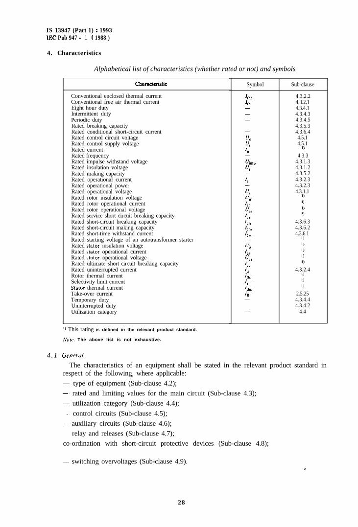
Alphabetical list of characteristics (whether rated or not) and symbols
Characmristic Symbol
Conventional enclosed thermal current ItheConventional free air thermal current 4hEight hour duty -Intermittent duty -Periodic duty -Rated breaking capacityRated conditional short-circuit current -Rated control circuit voltageRated control supply voltageRated currentRated frequency -Rated impulse withstand voltageRated insulation voltage
uintpvi
Rated making capacity -Rated operational currentRated operational power -Rated operational voltage chRated rotor insulation voltage “irRated rotor operational current IRated rotor operational voltage crRated service short-circuit breaking capacity IcsRated short-circuit breaking capacity IcnRated short-circuit making capacity IcmRated short-time withstand current IcwRated starting voltage of an autotransformer starter -Rated stator insulation voltageRated stator operational currentRated stator operational voltageRated ultimate short-circuit breaking capacityRated uninterrupted currentRotor thermal currentSelectivity limit currentStator thermal currentTake-over currentTemporary dutyUninterrupted dutyUtilization category
4.3.1.11)1)1)1)
4.3.6.34.3.6.24.3.6.1
1)
4.3.2.41)1)1)
2.5.254.3.4.44.3.4.2
4.4
‘1 This rating is defined in the relevant product standard.
Note. The above list is not exhaustive.
4 .1 Generul
The characteristics of an equipment shall be stated in the relevant product standard inrespect of the following, where applicable:- type of equipment (Sub-clause 4.2);- rated and limiting values for the main circuit (Sub-clause 4.3);- utilization category (Sub-clause 4.4);- control circuits (Sub-clause 4.5);- auxiliary circuits (Sub-clause 4.6);-.- relay and releases (Sub-clause 4.7);co-ordination with short-circuit protective devices (Sub-clause 4.8);
- switching overvoltages (Sub-clause 4.9).6
28
Is 13947 (Part 1) : 1993EC Pub 947 - 1 ( 1988 )
4.2 Type of equipment
The product standard shall state the following, where applicable:- kind. of equipment: e.g. contactor, circuit-breaker, etc. ;- number of poles ;
- kind of current;- interrupting medium;- operating conditions (method of operation, method of control, etc.).
Note. - The above list is not exhaustive.
4.3 Rated and limiting values for the main circuit
Ratings are assigned by the manufacturer. They shall be stated in accordance withSub-clauses 4.3.1 to 4.3.6 as required by the relevant product standard, but it is not necessaryto establish all the ratings listed.
4.3.1 Rated voltages
An equipment is defined by the following rated voltages:
Note. - Certain types of equipment may have more than one rated voltage or may have a rated voltagerange.
4.3.1.1 Rated operational voltage (U,)
A rated operational voltage of an equipment is a value of voltage which, combined with arated operational current, determines the application of the equipment and to which therelevant tests and the utilization categories are referred.
For single-pole equipment, the rated operational voltage is generally stated as the voltageacross the pole.
For multipole equipment, it is generally stated as the voltage between phases.
Notes I. - For certain devices and particular applications a different method of stating c’, may apply: this shouldbe stated in the relevant product standard.
2. - For multipole equipment for use on polyphase circuits a distinction may be made between:
uj equipment for use on systems where a single fitult to earth will not cause the full phase-to-phasevoltage to appear across a pole (i.e. unearthed and neutral earthed systems):
6) equipment for use on systems where a single fault to earth will cause the full phaseto-phase voltageto appear across a pole (i.e. phase earthed systems).
3. -An equipment may be assigned a number of combinations of rated operational voltages and ratedoperational currents or powers for different duties and utilization categories.
4. --An equipment may be assigned a number of rated operational voltages and associated making andbreaking capacities for different duties and utilization categories.
5. -Attention is drawn to the fact that the operational voltage may differ from the working voltage (seeSub-clause 2.5.52) within an equipment.
4.3.1.2 Rated insulation voltage (Vi)The rated insulation voltage of an equipment is the value of voltage to which dielectric
tests voltage and creepage distances are referred.In no case shall the maximum value of the rated operational voltage exceed that of the
rated insulation voltage.
Note. - For equipment not having a specified rated insulation voltage, the highest value of the rated operationalvoltage is considered to be the rated insulation voltage. .
29
IS 13947 (Part 1) : 1993IEC Pub 947 - 1 ( 1988 )
4.3.1.3 Rated impulse withstand voltage (Uimp)
The peak value of an impulse voltage of prescribed form and polarity-which the equipmentis capable of withstanding without failure under specified conditions of test and to which thevalues of the clearances are referred.
The rated impulse withstand voltage of an equipment shall be equal to or higher than thevalues stated for the transient overvoltages occurring in the circuit in which the equipment isfitted.
Note. - Preferred values of rated impulse withstand voltage are given in Table XII, page 143.
4.3.2 Currents
An equipment is defined by the following currents:
4.3.2.1 Conventional free air thermal current (Z,J
The conventional free air thermal current is the maximum value of test current to be usedfor temperature-rise tests of unenclosed equipment in free air (see Sub-clause 8.3.3.3).
The value of the conventional free air thermal current shall be at least equal to themaximum value of the rated operational current (see Sub-clause 4.3.2.3) of the unenclosedequipment in eight-hour duty (see Sub-clause 4.3.4.1).
Free air is understood to be air under normal indoor conditions reasonably free fromdraughts and external radiation.
Notes 1. - This current is not a rating and is not mandatorily marked on the equipment.
2. - An unenclosed equipment is an equipment supplied by the manufacturer without an enclosure or anequipment supplied by the manufacturer with an integral enclosure which is not normally intended tobe the sole equipment protective enclosure.
4.3.2.2 Conventional enclosed thermal current (Z,,,J
The conventional enclosed thermal current is the value of current stated by the manufac-turer to be used for the temperature-rise tests of the equipment when mounted in a specifiedenclosure. Such tests shall be in accordance with Sub-clause 8.3.3.3 and are mandatory if theequipment is described as enclosed equipment in the manufacturer’s catalogues and normallyintended for use with one or more enclosures of specified type and size (see Note 2).
The value of the conventional enclosed thermal current shall be at least equal to themaximum value of the rated operational current (see Sub-clause 4.3.2.3) of the enclosedequipment in eight-hour duty (see Sub-clause 4.3.4.1).
If the equipment is normally intended for use in unspecified enclosures, the test is notmandatory if the test for conventional free air thermal current (I,,,) has been made. In thiscase, the manufacturer shall be prepared to give guidance on the value of enclosed thermalcurrent or the derating factor.Notes 1. ~ This current is not a rating and is not mandatorily marked on the equipment
2. ~~ The conventional enclosed thermal current value may be for unventilated equipment in which case theenclosure used for the test shall be of the sire stated by the manufacturer a~ being the smallest that isapplicable in service. Alternatively, the value may be for a ventilated cquipmcnt according to themanufacturer’s data.
3. - An enclosed equipment is an equipment normally intended for USC with a spccilied type and size ofenclosure or intended for use with more than one type of enclosure.
4.3.2.3 Rated operational currents (Z,) or rated operational powers
A rated operational current of an equipment is stated by the manufacturer and takes intoaccount the rated operational voltage (see Sub-clause 4.3.1.1), the rated frequency (see
.
IS 13947 (Part 1) : 1993IEC Pub 947 - 1 ( 1988 )
Sub-clause 4.3.3), the rated duty (see Sub-clause 4.3.4), the utilization category (see Sub-clause 4.4) and the type of protective enclosure, if appropriate.
In the case of equipment for direct switching of individual motors, the indication of a ratedoperational current may be replaced or supplemented by an indication of the maximum ratedpower output, at the rated operational voltage considered, of the motor for which theequipment is intended. The manufacturer shall be prepared to state the relationship assumedbetween the operational current and the operational power, if any.
4.3.2.4 Rated uninterrupted current (I,)
The rated uninterrupted current of an equipment is a value of current, stated by themanufacturer, which the equipment can carry in uninterrupted duty (see Sub-clause4.3.4.2).
4.3.3 Rated frequencyThe supply frequency for which an equipment is designed and to which the other
characteristic values correspond.
Nore. --- The same equipment ma, be assigned a number or a range of rated frequencies or be rated for both a.c.and d.c.
4.3.4 Rated duties
The rated duties considered as normal are:
4.3.4.1 Eight-hour duty
A duty in which the main contacts of an equipment remain closed, whilst carrying a steadycurrent long enough for the equipment to reach thermal equilibrium but not for more thaneight hours without interruption.
Notes 1. - This is the basic duty on which the conventional thermal currents Z,, and Ithe of the equipment aredetermined.
2. - Interruption means breaking of the current by operation of the equipment.
4.3.4.2 Uninterrupted duty
A duty without any off-load period in which the main contacts of an equipment remainclosed, whilst carrying a steady current without interruption for periods of more than eighthours (weeks, months, or even years).
Note. --.- This kind of service is set apart from the eight-hour duty because oxides and dirt can accumulate on thecontacts and lead to progressive heating. Uninterrupted duty can be taken account of either by a deratingfactor, or by special design considerations (e.g. silver contacts).
4.3.4.3 Intermittent periodic dut,y or intermittent duty
A duty with on-load periods, in which the main contacts of an equipment remain closed,having a definite relation to off-load periods, both periods being too short to allow theequipment to reach thermal equilibrium.
Intermittent duty is characterized by the value of the current, the duration of the currentflow and by the on-load factor which is the ratio of the in-service period to the entire period,often expressed as a percentage.
Standardized values of on-load factor are 15%, 25%, 40% and 60%.According to the number of operating cycles which they shall be capable of carrying out
per hour, equipments are divided into the following classes:- class 1: 1 operating cycle per hour;
class 3: 3 operating cycles per hour; .,
31
IS 13947 (Part 1) : 1993IEC Pub 947 - 1 ( 1988 )
- class 12: 12 operating cycles per hour;- class 30: 30 operating cycles per hour;- class 120: 120 operating cycles per hour;- class 300 : 300 operating cycles per hour;- class 1200: 1 200 operating cycles per hour;- class 3 000: 3 000 operating cycles per hour;- class 12 000 : 12 000 operating cycles per hour;- class 30 000 : 30 000 operating cycles per hour;- class 120 000 : 120 000 operating cycles per hour;- class 300 000: 300 000 operating cycles per hour.
For intermittent duty with a large number of operating cycles per hour, the manufacturershall indicate, either in terms of the true cycle if this is known, or in terms of conventionalcycles designated by him, the values of the rated operational currents which shall be suchthat:
ci2dt d If,, x T or & x T
whichever is applicable
where T is the total operating cycle time.
Note. - The above formula does not take account of the switching arc energy.
A switching device @tended for intermittent duty may be designated by the characteristicsof the intermittent duty.
Example: An intermittent duty comprising a current flow of 100 A for 2 min in every 5 min may be stated as:100 A, class 12, 40%.
4.3.4.4 Temporary duty
Duty in which the main contacts of an equipment remain closed for periods insufficient toallow the equipment to reach thermal equilibrium, the unload periods being separated byoff-load periods of sufficient duration to restore equality of temperature with the coolingmedium.
Standardized values of temporary duty are 3 min, 10 min, 30 min, 60 min and 90 min withcontacts closed.
4.3.4.5 Periodic duty (151-04-11)
A type of duty in which operation, whether at constant or variable load, is regularlyrepeated.
4.3.5 Normal load and overload characteristics
This sub-clause gives general requirements concerning ratings under normal load andoverload conditions.
Note. ~~ Where applicable, the utilization categories referred to in Sub-clause 4.4 may include requirements inrespect of performance under overload conditions.
Detailed requirements are given in Sub-clause 7.2.4.
4.3.5.1 Ability to withstand motor switching overload currents
An equipment intended for switching motors shall be capable of withstanding the thermalstresses due to starting and accelerating a motor to normal speed and due to operatingoverloads. *
3 2
IS 13947 (Part 1) : 1993IEC Pub 947 - 1 ( 1988 )
The detailed requirements to meet these conditions are given in the relevant productstandard.
4.3.5.2 Rated making capacity
The rated making capacity of an equipment is a value of current, stated by the manu-facturer, which the equipment can satisfactorily make under specified making conditions.
The making conditions which shall be specified are:
- the applied voltage (see Sub-clause 2.5.32);
- the characteristics of the test circuit.
The rated making capacity is stated by reference to the rated operational voltage and ratedoperational current, according to the relevant product standard.
Note. - Where applicable. the relevant product standard states the relationship between rated making capacityand utilization category.
For a.c., the rated making capacity is expressed by the r.m.s. value of the symmetricalcomponent of the current, assumed to be constant.
Note. - For a.c.. the peak value of the current during the Crst half-cycles following the closing of the malncontacts of the equipment may be appreciably grcatcr than the peak value of the current under steadystate conditions used in the determination of making capacity, depending on the power-factor of thecircuit and the instant on the voltage wave when closing occurs.
An equipment should be capable of closing on a current having the ax. component equal to that whichdctincs its rated making capacity, whatever the value of the inherent d.c. component. wlthin the limitsresulting from the power-factors indicated in the relevant product standard.
4 . 3 . 5 . 3 Rated hrraking caprrcit?>
The rated breaking capacity of an equipment is a value of current, stated by themanufacturer, which the equipment can satisfactorily break, under specified breaking con-ditions.
The breaking conditions which shall be specified are:- the characteristics of the test circuit;
-- the power frequency recovery voltage.
The rated breaking capacity is stated by rcferencc to the rated operational voltage andrated operational current, according to the relevant product standard.
An equipment shall be capable of breaking any value of current up to and including itsrated breaking capacity.
Note. - A switching dcvicc may have more than one rated breaking capacity. each corresponding to an opcra-tional voltage and a utilization category.
For a.c., the rated breaking capacity is expressed by the r.m.s. value of the symmetricalcomponent of the current.
Note. Whcrc applicable, the rclcwnt p r o d u c t s t a n d a r d stata the ~-clat~on<h~p bctwcen rated hrcakinp capac i tyand utilimtion category.
4.3.6 Short-circuit c.llrrr.rrc.trri,FIic..v
This sub-clause gives general requirements concerning ratings under short-circuit con-ditions.
4.3.6. I Rrrtrd .slwt-tiuw \1~ith.~trrrld currotlt (I<,)
The rated short-time withstand current of an cquipmcnt is the value ol‘ short-t imewithstand current assigned to the equipment by the manuf~~cturcr that the cquipmcnt cancarry without damage, under the test condition\ \pccil‘icd in the rclcvant product stan-dard. .
3 3
IS 13947 (Part 1) : 1993IEC Pub 947 - 1 ( 1988 )
4.3.6.2 Rated short-circuit making capacity (I,)
The rated short-circuit making capacity of an equipment is the value of short-circuitmaking capacity assigned to that equipment by the manufacturer for the rated operationalvoltage, at rated frequency, and at a specified power-factor for a.c. or time constant for d.c.It is expressed as the maximum prospective peak current, under prescribed conditions.
4.3.6.3 Rated short-circuit breaking capacity (I,,)
The rated short-circuit breaking capacity of an equipment is the value of short-circuitbreaking capacity assigned to that equipment by the manufacturer for the rated operationalvoltage, at rated frequency, and at a specified power-factor for a.c. or time constant for d.c.It is expressed as the value of the prospective breaking current (r.m.s. value of the a.c.component in the case of a.c.), under prescribed conditions.
4.3.6.4 Rated conditional short-circuit current
The rated conditional short-circuit current of an equipment is the value of prospectivecurrent, stated by the manufacturer, which the equipment, protected by a short-circuitprotective device specified by the manufacturer, can withstand satisfactorily for the operatingtime of this device under the test conditions specified in the relevant product standard.
The details of the specified short-circuit protective device shall be stated by the manu-facturer.
Notes 1. -
2. -
For a.~., the rated conditional short-circuit current is expressed by the r.m.s. value of the a.c.component.The short-circuit protective device may either form an integral part of the equipment or be a separateunit.
4.4 Utilization category
The utilization category of an equipment defines the intended application and shall bespecified in the relevant product standard; it is characterized by one or more of the followingservice conditions :- current(s), expressed as multiple(s) of the rated operational current;- voltage(s), expressed as multiple(s) of the rated operational voltage;- power-factor or time-constant;- short-circuit performance;- selectivity ;- other service conditions, as applicable.
Examples of utilization categories for low-voltage switchgear and controlgear are given inAppendix A.
4.5 Control circuits
4.5.1 Electrical control circuits
The characteristics of electrical control circuits are:- kind of current;- rated frequency, if ac.;
34
IS 13947 (Pert 1) : 1993IEC Pub 947 - 1 ( 1988 )
- rated control circuit voltage U, (nature, and frequency II’ a.c.);
- rated control supply voltage U, (nature, and frequency if a.c.), where applicable.
Nore. - A distinction has been made above between the control circuit voltage, which is the voltage which wouldappear across the “a” contacts (see Sub-clause 2.3.12) in the control circuit, and the control supply voltage,which is the voltage applied to the input terminals of the control circuit of the eqqipment and may bedifferent from the control circuit voltage, due to the presence of built-in transformers, rectifiers, resistors,etc.
The rated control circuit voltage and rated frequency, if any, are the values on which theoperating and temperature-rise characteristics of the control circuit are based. The correctoperating conditions are based upon a value of the control supply voltage not less than 85%of its rated value, with the highest value of control circuit current flowing, nor more than110% of its rated value.
Note. - The manufacturer sh&u!d be prepared to state the value or values of the current taken by the controlcircuits at the rated contiol supply voltage.
The ratings and charaderisties of control circuit &vices shall comply with the require-ments of I E C Standard 947-5 (see note of Clause 1).
1.5.2 Air-supply control circuits (pneumatic or electro-pneumatic)The characteristics of air-supply control circuits are :
- rated pressure and its limits;- volumes of air, at atmospheric pressure, required for each closing and each opening
operation.The rated supply press& of a pneumatic or electro-pneumatic equipment is the air
pressure on which the operating characteristics of the pneumatic control system arebased.
4.6 Auxiliary circuits
The characteristics of auxiliary circuits are the number and kind of contacts (a-contact,b-contact, etc.) in each of these circuits and their ratings according to I E C Standard 947-5(see note of Clause 1).
The characteristics of auxiliary contacts and switches shall comply with the requirementsof the above standard.
4.7 Relays and releases
The following characteristics of relays and releases shall be stated in the relevant productstandard, where applicable :- type of relay or release ;- rated values ;
- current setting or current setting range;- time/current characteristics (for presentation of time/current characteristics, see Sub-
clause 4.8) ;- influence of ambient air temperature.
4.8 Co-ordination with short-circuit protective devices (SCPD)
The manufacturer shall state the type or the characteristics of the SCPD to be used with C)Iwithin the equipment, as the case may be, and the maximum prospective short-circuit current*
IS 13947 (Part 1) : 1993IEC Pub 947 - 1 ( 1988 )
for which the equipment, including the SCPD, is suitable, at the stated operational vol-tage(s).
Note. - It is recommended that the current be plotted as abscissa and the time as ordinate, using logarithmicscales. It is recommended that the current be plotted as a multiple of the current setting and the time inseconds on the standard graph sheet detailed in I E C Publication 269-I (First edition, Sub-clause 5.6.4)and I EC Publication 269-2 (Figures I to 7).
4.9 Switching overvoltages
The manufactuier shall specify the maximum value of switching overvoltages caused bythe operation of the switching device, when tested according to Sub-clause 8.3.3.5.4.
This value shall not exceed that of the rated impulse withstand voltage (see Sub-clause4.3.1.3).
5. Product information
5.1 Nature of information
The following information shall be given by the manufacturer, when required by therelevant product standard :
Identifi:cation.- manufacturer’s name or trademark ;
- type designation or serial number;- number of the relevant product standard, if the manufacturer claims compliance.
Characteristics.- rated operational voltages (see Sub-clause 4.3.1.1 and note to Sub-clause 5.2);- utilization category and rated operational currents (or rated powers or rated uninter-
rupted currents), at the rated operational voltages of the equipment (see Sub-clauses4.3.1.1, 4.3.2.3, 4.3.2.4 and 4.4). In certain cases, this information may have to becompleted by the v,alue of the reference ambient air temperature at which the equipmenthas been calibrated ;
-- the value of the rated frequency/frequencies, e.g.: + 50 Hz. 50 Hz160 Hz. and or theindication “d.c.” or the symbol ---z;
- rated duty, with the indication of the class of intermittent duty, if any (see Sub-clause4.3.4);
- rated making and/or breaking capacities. These indications may be repkaced, where appli-cable, by the indication of the utilization category;
- rated insulation voltage (see Sub-clause 4.3.1.2);- rated impulse withstand voltage (see Sub-clause 4.3.1.3);- switching overvoltage (see Sub-clause 4.9);- rated short-time withstand current together with its duration, where applicable (see
Sub-clause 4.3.6.1);- rated short-circuit making and/or breaking capacities, where applicable (see Sub-clauses
4.3.6.2 and 4.3.6.3);-- rated conditional short-circuit current, where applicable (see Sub-clause 4.3.c.4);
36
IS 13947 (Part 1) : 1993IECPub947-l(1988)
- IP code, in case of enclosed equipment (see Appendix C);- pollution degree (see Sub-clause 6.1.3.2);
type and maximum ratings of short-circuit protective device, where applicable;
- class of protection against electric shock (under consideration), where applicable;- rated control circuit voltage, kind of current and frequency.- rated control supply voltage, kind of current and frequency, if different from those of the
control coil ;- rated supply pressure of the air-pressure and limits of pressure variations (for air-pressure
controlled equipment);- suitability for isolation.Note. - This list is not exhaustive.
5.2 Marking
All relevant information, as detailed in Sub-clause 5.1, which is to be marked on theequipment, shall be specified in the relevant product standard.
Markings shall be indelible and easily legible.
Marking of the manufacturer’s name or trademark and type designation or serial numberis mandatory on the equipment and preferably on the nameplate, if any, in order to permitthe complctc data to be obtained from the manufacturer.
ivorcz. - In the USA and Canada. the rated operational voltage (/, may be marked as follows:
cri on equipment for use on three-phase - four-wire systems, by both the value of phase-to-earth voltageand that of phase-to-phase voltage, e.g. 277/480 V;
h) on equipment for USC on three-phase three-wire systems, by the value of phase-to-phase voltage, e.g.4x0 v.
The following information shall also be marked and visible after mounting:
- direction of movement of the actuator (see Sub-clause 7.1.4.2) if applicable;
- indication of the position of the actuator (see also Sub-clauses 7.1.5.1 and 7.1.5.2);
- approval or certification mark, if applicable;
.-~ for miniaturized equipment, symbol, colour code or letter code;- terminal identification and marking (see Sub-clause 7.1.7.4);- IP code and class of protection against electric shock, when applicable (marked prefer-
ably on the equipment as far as possible);suitability for isolation, where applicable, with the ,symbol F-
This symbol may be completed with the appropriate qualifying symbol of the switchingfunction of the equipment:e.g. __/&_ for a switch disconnector.Note,. l‘hcsc symbols arc in accordance with I E C Publication 6 1 7 - 7 .
5.3 1n.struc~lion.s ,fbr instrrllrrlion. opcrcition trnd mrrinlcriaric~c
The manufacturer shall specify in his documents or catalogucs the conditions, if any, forinstallation, operation and maintcnancc of the equipment during operation and after afault. (:
37
IS 13947 (Part 1) : 1993IEC Pub 947 - 1 ( 1988 )
If necessary, the instructions for the transport, installation and operation of the equipmentshall indicate the measures that are of particular importance for the proper and correctinstallation, commissioning and operation of the equipment.
These documents shall indicate the recommended extent and frequency of maintenance, ifany.
Nore. - All equipment covered by this standard is not necessarily designed to be maintained.
6. Normal service, mounting and transport conditions
6.1 Normal service conditions
Equipment complying with this standard shall be capable of operating under the followingstandard conditions :
Nofe. - For non-standard conditions in service, see Appendix B. These may require agreement between manu-facturer and user.
6.1.1 Ambient air temperature
The ambient air temperature does not exceed +40 “C and its average over a period of 24 hdoes not exceed +35 “C.
The lower limit of the ambient air temperature is -5 “C.Ambient air temperature is that existing in the vicinity of the equipment if supplied
without enclosure, or in the vicinity of the enclosure if supplied with an enclosure.
Notes 1. - Equipment intended to be used in ambient air temperature above +40 “C (e.g. in forges, boiler rooms,tropical countries) or below -5 “C (e.g. -25 “C, as required by I E C Publication 439-l for outdoorinstalled low-voltage switchgear and controlgear assemblies) should be designed or used according tothe relevant product standard, where applicable, or according to agreement between manufacturer anduser. Information given in the manufacturer’s catalogue may take the place of such an agreement.
2. -- Standard reference air temperature for certain types of equipment, e.g.. circuit-breakers or overloadrelays for starters, is indicated in the relevant product standard.
6.1.2 Altitude
The altitude of the site of installation does not exceed 2 000 m.
Note. - For equipment to be used at higher altitudes, it is necessary to take into account the reduction of thedielectric strength and the cooling effect of the air. Electrical equipment intended to operate in theseconditions shall be designed or used in accordance with an agreement between manufacturer anduser.
6.1.3 A tmospheric conditions
6.1.3.1 Humidity
The relative humidity of the air does not exceed 50% at a maximum temperature of+40 “C. Higher relative humidities may be permitted at lower temperatures, e.g. 90% at+20 “C. Special measures may be necessary in cases of occasional condensation due tovariations in temperature.
Nope. - Pollution degrees, as stated in Sub-clause 6.1.3.2, define the environmental conditions more precisely.
IS 13947 (Part 1) : 1993IEC Pub 947 - 1 ( 1988 )
6.1.3.2 Pollution degree
The pollution.degree (see Sub-clause 2.5.58) refers to the environmental conditions forwhich the equipment is intended.
Note. - The micro-environment of the creepage distance or clearance and not the environment of the equipmentdetermines the effect on the insulation. The micro-environment might he better or worse than theenvironment of the equipment. It includes all factors influencing the insulation, such as climatic andeleitromagnetic conditions, generation of pollution, etc.
For equipment intended for use within an enclosure or provided with an integral en-closure, the pollution degree of the environment in the enclosure is applicable.
For the purpose of evaluating clearances and creepage distances, the followmg fourdegrees of pollution of the micro-environment are established (clearances and creepagedistances according to the different pollution degrees are given in Tables XIII and XV):
Pollution degree 1:
No pollution or only dry, non-conductive
Pollution degree 2:
Normally, only non-conductive pollution
pollution occurs.
occurs. Occasionally, however, a temporaryconductivity caused by condensation may be expected.
Pollution degree 3:
Conductive pollution occurs, or dry, non-conductive pollution occurs which becomesconductive due to condensation.
Pollution degree 4:
The pollution generates persistent conductivity caused, for instance, by conductive dust orby rain or snow.
Stqndard pollution degree of industrial applications:
Unless otherwise stated by the relevant product standard, equipment for industrial appli-cations is generally for use in pollution degree 3 environment. However, other pollutiondegrees may be considered to apply depending upon particular applications or the micro-environment.
Note. - The pollution degree of the micro-environment for the equipment may be influenced by installation in anenclosure.
Standard pollution degree of household and similar applications.
Unless otherwise stated by the relevant product standard, equipment for household andsimilar applications is generally for use in pollution degree 2 environment.
6.1.4 Shock and vibrations
Standard conditions of shock and vibration to which the equipment can be submitted areunder consideration.
6.2 Conditions during transport and storage
A special agreement shall be made between user and manufacturer if the conditions duringtransport and storage, e.g. temperature and humidity, differ from those defined in Sub-clause6.1, except that, unless otherwise specified, the following temperature range applies duringtransport and storage: between -25 “C and + 55 “C and, for short periods not exceeding24 hours, up to +70 “C. *
33
IS 13947 (Part 1) : 1993IEC Pub 947 - 1 ( 1988 )
Equipment subjected to these extreme temperatures without being operated shall notundergo any irreversible damage and shall then operate normally under the specifiedconditions.
6.3 Mounting
The equipment shall be mounted in accordance with the manufacturer’s instructions.
7. Constructional and performance requirements
7.1 Constructional requirements
7.1.1 Materials
Materials shall be suitable for the particular application and shall enable the equipment tocomply with the relevant test requirements.
Special attention shall be called to flame and humidity resisting qualities, and to thenecessity to protect certain insulating materials against humidity.
Note. - Requirements are under consideration.
7. I. 1.1 Insulating materials
Under consideration.
7.1.2 Currem-carrying parts and their connections
Current-carrying parts shall have the necessary mechanical strength and current-carryingcapacity for their intended use.
For electrical connections, no contact pressure shall be transmitted through insulatingmaterial other than ceramic or other material with characteristics not less suitable, unlessthere is sufficient resiliency in the metallic parts to compensate for any possible shrinkage oryielding of the insulation material.
7.1.3 Clearances and creepage distances
For equipment tested according to Sub-clause 8.3.3.4 of this standard, minimum values aregiven in Tables XIII and XV.
Electrical requirements are given in Sub-clause 7.2.3.In the other cases, guidance for minimum values is given in the relevant product stan-
dard.
7.1.4 Actuator
7.1.4.1 /nsulation
The actuator of the equipment shall be insulated from the live parts for the ratedinsulation voltage and, if applicable, the rated impulse withstand voltage.
Moreover:- if it is made of metal, it shall be capable of being satisfactorily connected to a protective
conductor unless it is provided with additional reliable insulation;- if it is made of or covered by insulating material, any internal metal part, which might
become accessible in the event of insulation failure, shall also be insulated from live partsfor the rated insulation voltage.
40
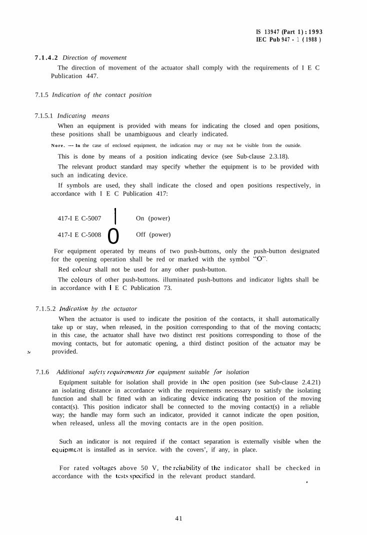
IS 13947 (Part 1) : 1993IEC Pub 947 - 1 ( 1988 )
7.1.4.2 Direction of movement
The direction of movement of the actuator shall comply with the requirements of I E CPublication 447.
7.1.5 Indication of the contact position
7.1.5.1 Indicating means
When an equipment is provided with means for indicating the closed and open positions,these positions shall be unambiguous and clearly indicated.
Nore. - In the case of enclosed equipment, the indication may or may not be visible from the outside.
This is done by means of a position indicating device (see Sub-clause 2.3.18).
The relevant product standard may specify whether the equipment is to be provided withsuch an indicating device.
If symbols are used, they shall indicate the closed and open positions respectively, inaccordance with I E C Publication 417:
417-I E C-5007I
On (power)
417-I E C-5008 0 Off (power)
For equipment operated by means of two push-buttons, only the push-button designatedfor the opening operation shall be red or marked with the symbol “0”.
Red colour shall not be used for any other push-button.
The colours of other push-buttons. illuminated push-buttons and indicator lights shall bein accordance with I E C Publication 73.
7.1.5.2 lndiwtion by the actuator
When the actuator is used to indicate the position of the contacts, it shall automaticallytake up or stay, when released, in the position corresponding to that of the moving contacts;in this case, the actuator shall have two distinct rest positions corresponding to those of themoving contacts, but for automatic opening, a third distinct position of the actuator may beprovided.
7.1.6 Additional safkt!’ requiremrnts .for equipment suitable ,for isolation
Equipment suitable for isolation shall provide in the open position (see Sub-clause 2.4.21)an isolating distance in accordance with the requirements necessary to satisfy the isolatingfunction and shall bc fitted with an indicating dcvicc indicating the position of the movingcontact(s). This position indicator shall be connected to the moving contact(s) in a reliableway; the handle may form such an indicator, provided it cannot indicate the open position,when released, unless all the moving contacts are in the open position.
Such an indicator is not required if the contact separation is externally visible when theequipme.; is installed as in service. with the covers’, if any, in place.
For rated voltages above 50 V, the reliability of the indicator shall be checked inaccordance with the tests specified in the relevant product standard.
.
41
IS 13947 (Part 1) : 1993IEC Pub 947 - 1 ( 1988 )
7.1.7 Terminals
7.1.7.1 Constructional requirements
All parts of terminals which maintain contact and carry current shall be of metal havingadequate mechanical strength.
Terminal connections shall be such that the conductors may be connected by means ofscrews, springs or other equivalent means so as to ensure that the necessary contact pressureis maintained.
Terminals shall be so constructed that the conductors can be clamped between suitablesurfaces without any significant damage either to conductors or terminals.
Terminals shall not allow the conductors to be displaced or be displaced themselves in amanner detrimental to the operation of equipment and the insulation voltage shall not bereduced below the rated values.
Examples of terminals are given in Appendix D.The requirements of this sub-clause shall be verified by the tests of Sub-clauses 8.2.4.2,
8.2.4.3 and 8.2.4.4, as applicable.
Note. - North American countries have particular requirements for terminals suitable for aluminium conductorsand marking to identify the use of aluminium conductors.
7.1.7.2 Connecting capacity
The manufacturer shall state the type (rigid - solid or stranded - or flexible), theminimum and the maximum cross-sections of conductors for which the terminal is suitableand, if applicable, the number of conductors simultaneously connectable to the terminal.However, the maximum cross-section shall not be smaller than that stated in Sub-clause8.3.3.3 for the temperature-rise test and the terminal shall be suitable for conductors of thesame type (rigid - solid or stranded - or flexible) at least 2 sizes smaller, as given in theappropriate column of Table I.
Netes 1. - Conductor cross-sections smaller than the minimum may be required in different product stan-dards.
2. - Because of voltage drop and other considerations, the product standards may require the terminals tobe suitable for conductors of cross-sections larger than those specified for the temperature-rise test.The relationship between conductor cross-sections and rated currents may be given in the relevantproduct standards.
Standard values of cross-section of round copper conductors (both metric andAWG/MCM sizes) are shown in Table I which also gives the approximate relationshipbetween IS0 metric and AWG/MCM sizes. -(p_
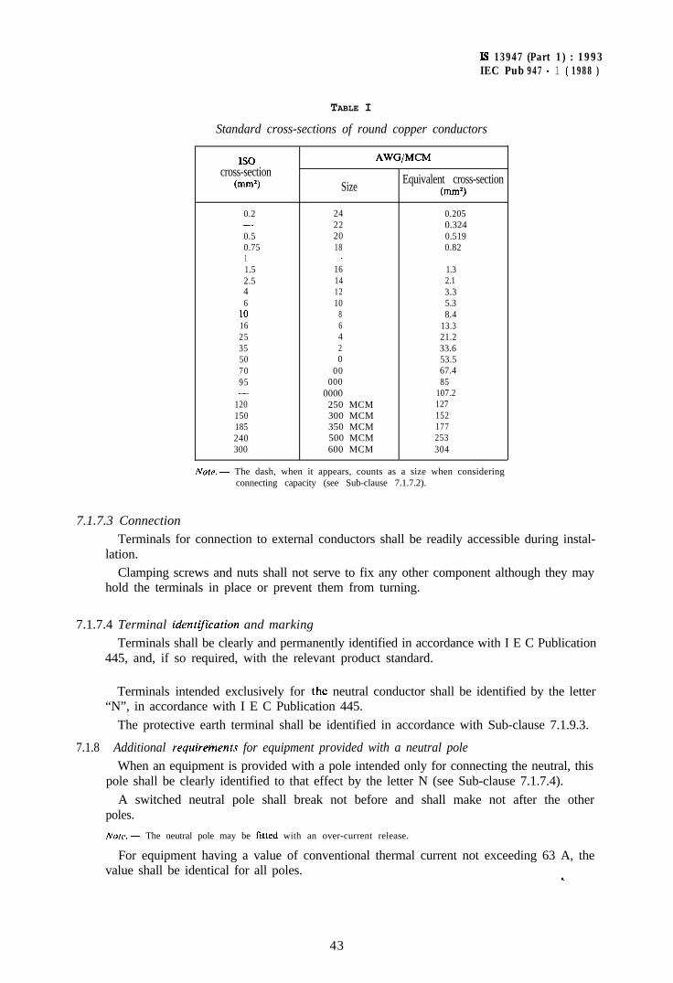
Is 13947 (Part 1) : 1993IEC Pub 947 - 1 ( 1988 )
TABLE I
Standard cross-sections of round copper conductors
IS0cross-section
(mm21 Size
AWG/MCM
Equivalent cross-section(mm3
0.2 24 0.205- 22 0.3240.5 20 0.5190.75 18 0.821 -1.5 16 1.32.5 14 2.14 12 3.36 10 5.3
10 8 8.416 6 13.325 4 21.235 2 33.650 0 53.570 00 67.495 000 85- 0000 107.2
120 250 MCM 127150 300 MCM 152185 350 MCM 177240 500 MCM 253300 600 MCM 304
Nore. - The dash, when it appears, counts as a size when consideringconnecting capacity (see Sub-clause 7.1.7.2).
7.1.7.3 Connection
Terminals for connection to external conductors shall be readily accessible during instal-lation.
Clamping screws and nuts shall not serve to fix any other component although they mayhold the terminals in place or prevent them from turning.
7.1.7.4 Terminal ident@ution and marking
Terminals shall be clearly and permanently identified in accordance with I E C Publication445, and, if so required, with the relevant product standard.
Terminals intended exclusively for ihe neutral conductor shall be identified by the letter“N”, in accordance with I E C Publication 445.
The protective earth terminal shall be identified in accordance with Sub-clause 7.1.9.3.
7.1.8 Additional reyuire%ents for equipment provided with a neutral pole
When an equipment is provided with a pole intended only for connecting the neutral, thispole shall be clearly identified to that effect by the letter N (see Sub-clause 7.1.7.4).
A switched neutral pole shall break not before and shall make not after the otherpoles.
NOM. - The neutral pole may be litted with an over-current release.
For equipment having a value of conventional thermal current not exceeding 63 A, thevalue shall be identical for all poles. *
43
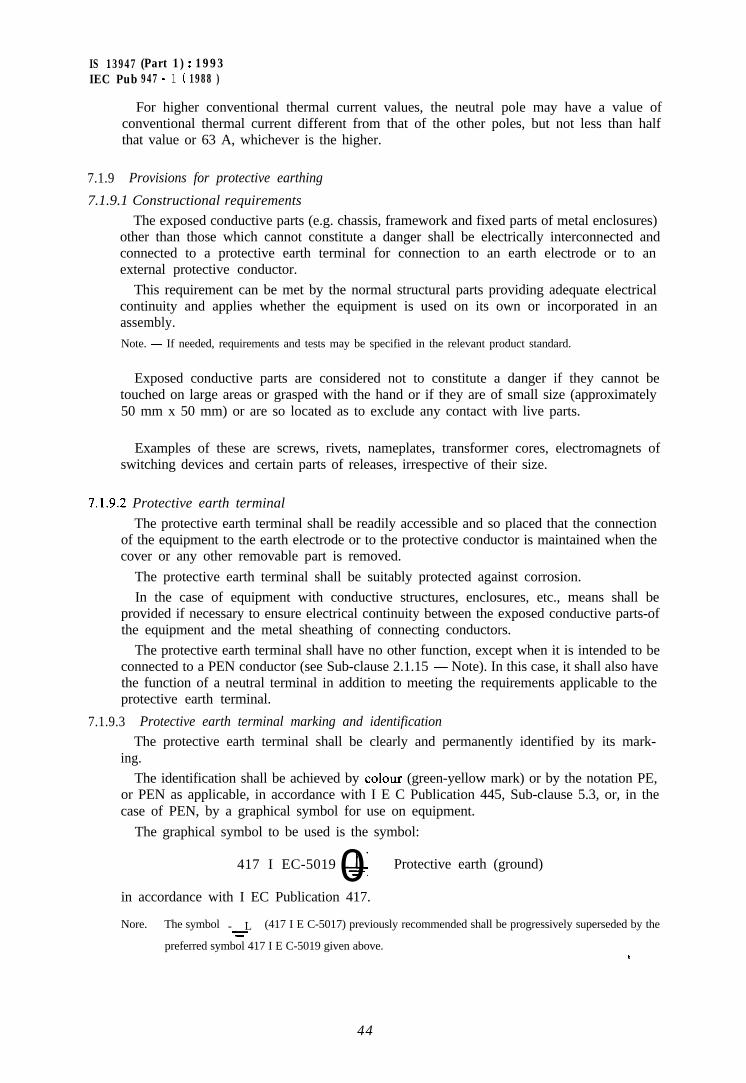
IS 13947 (Part 1) : 1993IEC Pub 947 - 1 ( 1988 )
For higher conventional thermal current values, the neutral pole may have a value ofconventional thermal current different from that of the other poles, but not less than halfthat value or 63 A, whichever is the higher.
7.1.9 Provisions for protective earthing
7.1.9.1 Constructional requirements
The exposed conductive parts (e.g. chassis, framework and fixed parts of metal enclosures)other than those which cannot constitute a danger shall be electrically interconnected andconnected to a protective earth terminal for connection to an earth electrode or to anexternal protective conductor.
This requirement can be met by the normal structural parts providing adequate electricalcontinuity and applies whether the equipment is used on its own or incorporated in anassembly.Note. - If needed, requirements and tests may be specified in the relevant product standard.
Exposed conductive parts are considered not to constitute a danger if they cannot betouched on large areas or grasped with the hand or if they are of small size (approximately50 mm x 50 mm) or are so located as to exclude any contact with live parts.
Examples of these are screws, rivets, nameplates, transformer cores, electromagnets ofswitching devices and certain parts of releases, irrespective of their size.
7.1.9.2 Protective earth terminal
The protective earth terminal shall be readily accessible and so placed that the connectionof the equipment to the earth electrode or to the protective conductor is maintained when thecover or any other removable part is removed.
The protective earth terminal shall be suitably protected against corrosion.In the case of equipment with conductive structures, enclosures, etc., means shall be
provided if necessary to ensure electrical continuity between the exposed conductive parts-ofthe equipment and the metal sheathing of connecting conductors.
The protective earth terminal shall have no other function, except when it is intended to beconnected to a PEN conductor (see Sub-clause 2.1.15 - Note). In this case, it shall also havethe function of a neutral terminal in addition to meeting the requirements applicable to theprotective earth terminal.
7.1.9.3 Protective earth terminal marking and identification
The protective earth terminal shall be clearly and permanently identified by its mark-ing.
The identification shall be achieved by colour (green-yellow mark) or by the notation PE,or PEN as applicable, in accordance with I E C Publication 445, Sub-clause 5.3, or, in thecase of PEN, by a graphical symbol for use on equipment.
The graphical symbol to be used is the symbol:
417 I EC-5019 &0 Protective earth (ground)
in accordance with I EC Publication 417.
Nore. - The symbol - L=
(417 I E C-5017) previously recommended shall be progressively superseded by the
preferred symbol 417 I E C-5019 given above.S
44
7.2 Performance requirements
The following requirements apply to clean new equipment unless otherwise stated in therelevant product standard.
7.2. 1 Operuting conditions
7.2. 1.1 General
The equipment shall be operated in accordance with the manufacturer’s instructions or therelevant product standard, especially for equipment with dependent manual operation wherethe making and breaking capacities may depend on the skill of the operator.
45
IS 13947 (Part 1) : 1993IEC Pub 947 - 1 ( 1988 )
7.1.10 Enclosures for equipmentThe following requirements are only applicable to enclosures supplied or intended to be
used with the equipment.
7.1.10.1 DesignThe enclosure shall be so designed that, when it is opened and other protective means, if
any, are removed, all parts requiring access for installation and maintenance, as prescribedby the manufacturer, are readily accessible.
Sufficient space shall be provided inside the enclosure for the accommodation of externalconductors from their point of entry into the enclosure to the terminals to ensure adequateconnection.
The fixed parts of a metal enclosure shall be electrically connected to the other exposedconductive parts of the equipment and connected to a terminal which enables them to beearthed or connected to a protective conductor.
Under no circumstances shall a removable metal part of the enclosure be insulated fromthe part carrying the earth terminal when the removable part is in place.
The removable parts of the enclosure shall be firmly secured to the fixed parts by a devicesuch that they cannot be accidentally loosened or detached owing to the effects of operationof the equipment or vibrations.
When an enclosure is so designed as to allow the covers to be opened without the use oftools, means shall be provided to prevent loss of the fastening devices.
An integral enclosure is considered to be a non-removable part.If the enclosure is used for mounting push-buttons, it shall not be possible to remove the
buttons from the outside of the enclosure.
7.1.10.2 Insulation
Jf, in order to prevent accidental contact between a metallic enclosure and live parts, theenclosure is partly or completely lined with insulating material, then this lining shall besecurely fixed to the enclosure.
7.1.11 Degrees qf‘protection of enclosed equipment
Degrees of protection of enclosed equipment and relevant tests are given in Appen-dix C.
7.2.1.2 Limits of operation of power operated equipment
Unless otherwise stated in the relevant product standard, electromagnetic and electro-pneumatic equipment shall close with any control supply voltage between 85% and 1 IO?! of
IS 13947 (Part 1) : 1993IEC Pub 947 - 1 ( 1988 )
its rated value US and an ambient air temperature between -5 “C and +40 “C. These limitsapply to d.c. or a.c. as appropriate.
For pneumatic and electro-pneumatic equipment, unless otherwise stated, the limits of theair supply pressure are 85% and 110% of the rated pressure.
Where a range of operation is given, the value of 85% shall apply to the lower limit of therange, and the value of 110% to the upper limit of the range.
Note. - For latched equipment, operating limits should be agreed upon between manufacturer and user.
For electromagnetic and electro-pneumatic equipment, the drop-out voltage shall not behigher than 75% of the rated control supply voltage US nor lower than 20% of (I, in the caseof a.c. at rated frequency or 10% of cl, in the case of d.c.
For pneumatic and electro-pneumatic equipment, unless otherwise stated, opening shalloccur at a pressure between 75% and 10% of the rated pressure.
Where a range of operation is given, the value of 20% or lo%, as the case may be, shallapply to the upper limit of the range, and the value of 75% to the lower limit of therange.
In the case of coils, the limiting drop-out values apply when the coil circuit resistance isequal to that obtained at -5 “C. This may be verified by a calculation based on the valuesobtained at normal ambient temperature.
7.2.1.3 Limits of operation of under-voltage relays and releases
a) Operating voltage
An under-voltage relay or release, when associated with a switching device, shalloperate to open the equipment even on a slowly falling voltage within the range between70% and 35% of its rated voltage.
Note. - A no-voltage release is a special form of under-voltage release in which the operating voltage isbetween 35% and 10% of the rated supply voltage.
An under-voltage relay or release shall prevent the closing of the equipment when thesupply voltage is below 35% of the rated voltage of the relay or release; it shall permitclosing of the equipment at supply voltages equal to or above 85% of its rated value. Unlessotherwise stated in the relevant product standard, the upper limit of the supply voltage shallbe 110% of its rated value.
The figures given above apply equally to d.c. and to a.c. at rated frequency.
h) Operating time
For a time-delay under-voltage relay or release, the time-lag shall be measured fromthe instant when the voltage reaches the operating value until the instant when the relayor release actuates the tripping device of the equipment.
7.2.1.4 Limits of operation of shunt releases
A shunt release for opening shall cause tripping under all operating conditions of anequipment when the supply voltage of the shunt release measured during the tripping
c
Is 13947 (Part 1) : 1993IEC Pub 947 - 1 ( 1988 )
operation remains between 70% and 110% of the rated control supply voltage and, whena.c., at the rated frequency.
7.2.1.5 Limits of operation of current operated relays and releases
Limits of operation of current operated relays and releases shall be stated in the relevantproduct standard.
Note. - ‘The term “current operated relays and releases” covers over-current relays or releases, overload relays orreleases, reverse current relays or releases, etc.
7.2.2 Temperature-rise
The temperature-rise of the parts of an equipment, measured during a test carried outunder the conditions specified in Sub-clause 8.3.3.3, shall not exceed the values stated in thissub-clause.
NOM I. - Temperature-rise in normal service may differ from the test values, depending on the installationconditions and size of connected conductors.
2. - The temperature-rise limits given in Tables II and IX1 apply to equipment tested in new and cleancondition. Different values may be prescribed by product standards for different test conditions andfor devices of small dimensions but not exceeding the above values by more than 10 K.
7.2.2.1 Terminals
The temperature-rise of terminals shall not exceed the values stated in Table II.
7.2.2.2 Accessible parts
The temperature-rise of accessible parts shall not exceed the values stated in Table III.
Note. - The temperature-rise limits of other parts are given in Sub-clause 7.2.2.8.
7.2.2.3 Ambient air temperature
The temperature-rise limits given in Tables II and III are applicable only if the ambient airtemperature remains within the limits given in Sub-clause 6.1.1.
7.2.2.4 Main circuit
The main circuit of an equipment shall be capable of carrying the conventional thermalcurrent of the equipment without the temperature-rises exceeding the limits specified inTables II and III when tested in accordance with Sub-clause 8.3.3.3.4.
7.2.2.5 Control circuits
The control circuits of an equipment, including control circuit devices to be used for theclosing and opening operations of an equipment, shall permit the rated duty according toSub-clause 4.3.4 and also the temperature-rise tests specified in Sub-clause 8.3.3.3.5 to bemade without the temperature-rise exceeding the limits specified in Tables II and III.
7.2.2.6 Windings of coils and electromagnets
With current flowing through the main circuit the windings of coils and electromagnetsshall withstand their rated voltage without the temperature-rise exceeding the limits specifiedin Sub-clause 7.2.2.8 when tested in accordance with Sub-clause 8.3.3.3.6.
Note. -- This sub-clause does not apply to pulse-operated coils. whose operating conditions are defined by themanufacturer. c
47
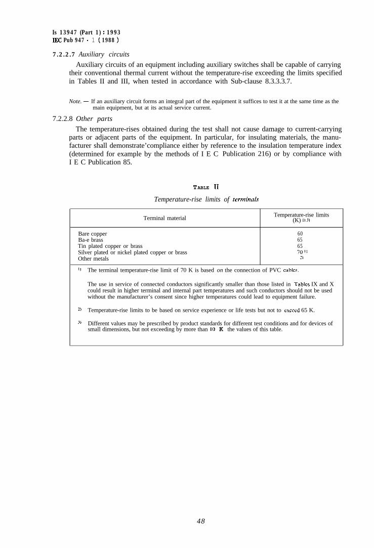
Is 13947 (Part 1) : 1993IEC Pub 947 - 1 ( 1988 )
7.2.2.7 Auxiliary circuits
Auxiliary circuits of an equipment including auxiliary switches shall be capable of carryingtheir conventional thermal current without the temperature-rise exceeding the limits specifiedin Tables II and III, when tested in accordance with Sub-clause 8.3.3.3.7.
Note. - If an auxiliary circuit forms an integral part of the equipment it suffices to test it at the same time as themain equipment, but at its actual service current.
7.2.2.8 Other parts
The temperature-rises obtained during the test shall not cause damage to current-carryingparts or adjacent parts of the equipment. In particular, for insulating materials, the manu-facturer shall demonstrate’compliance either by reference to the insulation temperature index(determined for example by the methods of I E CI E C Publication 85.
TABLE II
Publication 216) or by compliance with
Temperature-rise limits of terminds
Terminal material Temperature-rise limits(K) 1) 3)
Bare copper 60Ba-e brass 65Tin plated copper or brass 65Silver plated or nickel plated copper or brass 70 ‘)Other metals 3
I) The terminal temperature-rise limit of 70 K is based on the connection of PVC cables.
The use in service of connected conductors significantly smaller than those listed in Tables IX and Xcould result in higher terminal and internal part temperatures and such conductors should not be usedwithout the manufacturer’s consent since higher temperatures could lead to equipment failure.
2, Temperature-rise limits to be based on service experience or life tests but not to exceed 65 K.
3, Different values may be prescribed by product standards for different test conditions and for devices ofsmall dimensions, but not exceeding by more than 10 K the values of this table.
48
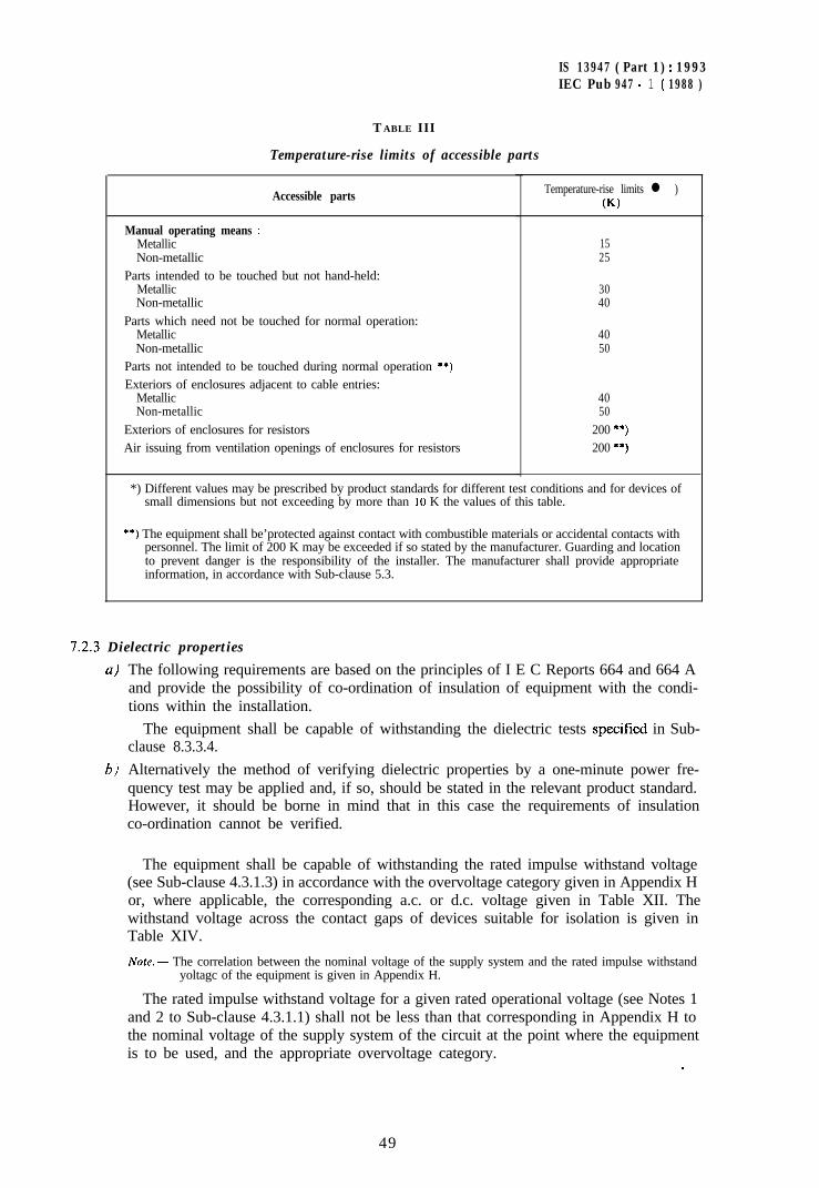
IS 13947 ( Part 1) : 1993IEC Pub 947 - 1 ( 1988 )
T ABLE III
Temperature-rise limits of accessible parts
Accessible parts
Manual operating means :MetallicNon-metallic
Parts intended to be touched but not hand-held:MetallicNon-metallic
Parts which need not be touched for normal operation:MetallicNon-metallic
Parts not intended to be touched during normal operation **)Exteriors of enclosures adjacent to cable entries:
MetallicNon-metallic
Exteriors of enclosures for resistorsAir issuing from ventilation openings of enclosures for resistors
Temperature-rise limits l )(K)
1525
3040
4050
4050
200 **)200 **)
*) Different values may be prescribed by product standards for different test conditions and for devices ofsmall dimensions but not exceeding by more than 10 K the values of this table.
**) The equipment shall be’protected against contact with combustible materials or accidental contacts withpersonnel. The limit of 200 K may be exceeded if so stated by the manufacturer. Guarding and locationto prevent danger is the responsibility of the installer. The manufacturer shall provide appropriateinformation, in accordance with Sub-clause 5.3.
1.2.3 Dielectric properties
a)
6)
The following requirements are based on the principles of I E C Reports 664 and 664 Aand provide the possibility of co-ordination of insulation of equipment with the condi-tions within the installation.
The equipment shall be capable of withstanding the dielectric tests specilied in Sub-clause 8.3.3.4.
Alternatively the method of verifying dielectric properties by a one-minute power fre-quency test may be applied and, if so, should be stated in the relevant product standard.However, it should be borne in mind that in this case the requirements of insulationco-ordination cannot be verified.
The equipment shall be capable of withstanding the rated impulse withstand voltage(see Sub-clause 4.3.1.3) in accordance with the overvoltage category given in Appendix Hor, where applicable, the corresponding a.c. or d.c. voltage given in Table XII. Thewithstand voltage across the contact gaps of devices suitable for isolation is given inTable XIV.
,
Note. - The correlation between the nominal voltage of the supply system and the rated impulse withstandyoltagc of the equipment is given in Appendix H.
The rated impulse withstand voltage for a given rated operational voltage (see Notes 1and 2 to Sub-clause 4.3.1.1) shall not be less than that corresponding in Appendix H tothe nominal voltage of the supply system of the circuit at the point where the equipmentis to be used, and the appropriate overvoltage category.
c
49
Is 13947 (Part 1) : 1993IECPub947-l(1988)
c) For verifying the condition of the equipment after performance tests, the one minutepower frequency test voltage is used in accordance with the relevant product stan-dard.
7.2.3.1
a)
Jmpulse withstand voltage of the main circuitClearances from live parts to parts intended to be earthed and between poles shallwithstand the test voltage given in Table XII appropriate to the rated impulse withstandvoltage.
6) Clearances across the open contacts shall withstand:- the impulse withstand voltage specified, where applicable, in the relevant product
standard ;
- for equipment designated as suitable for isolation, the test voltage given in Table XIVappropriate to the rated impulse withstand voltage.
C)
7.2.3.2
a)
Solid insulation of equipment associated with clearances a) and/or 6) shall withstand theimpulse voltages specified in a) and/or b), as applicable.
Impulse withstand voltages of auxiliary and control circuitsAuxiliary and control circuits which operate directly from the main circuit at therated operational voltage shall comply with the requirements of Sub-clause 7.2.3.1 a)and c).
6) Auxiliary and control circuits which do not operate directly from the main circuit mayhave an overvoltage withstand capacity different from that of the main circuit. Clear-ances and associated solid insulation of such circuits, whether a.c. or d.c., shall withstandthe appropriate voltage in accordance with Appendix H.
7.2.3.3 ClearancesClearances shall be sufficient to enable the equipment to withstand the rated impuise
withstand voltage, according to Sub-clauses 7.2.3.1 and 7.2.3.2.
Clearances shall be higher than the values g’ven in Table XIII, for case B-homogeneousfield (see Sub-clause 2.5.62) and verified by a sampling test according to Sub-clause8.3.3.4.3. This test is not required if the clearances, related to the rated impulse withstandvoltage and pollution degree,,are higher than the values given in Table XIII for case A-in-homogeneous field.
The method of measuring clearances is given in Appendix G.
7.2.3.4 Creepage distancesa) Dimensioning
For pollution degrees 1 and 2, creepage distances shall not be less than the associatedclearances selected according to Sub-clause 7.2.3.3. For pollution degrees 3 and 4 thecreepage distances shall not be less than the case A clearances to reduce the risk ofdisruptive discharge due to overvoltages, even if the clearances are smaller than the valuesfor case A as permitted in Sub-clause 7.2.3.3.
The method of measuring creepage distances is given in Appendix G.Creepage distances shall correspond to a pollution degree as specified in Sub-clause
6.1.3.2 or to that defined in the relevant product standard and to the correspondingmaterial group at the rated insulation (or working) voltage given in Table XV.
c
50
IS 13947 (Part 1) : 1993IEC Pub 947 - 1 ( 198% )
Material groups are classified as follows, according to the range of values of thecomparative tracking index (CTI) (see Sub-clause 2.565) :
- Material Group I 600 < CT1
- Material Group II 400 < CT1 < 600- Material Group IIIa 175 < CT1 < 400- Material Group IIIb 100 < CT1 < 175
Notes ,J. - The CT’1 values refer to the values obtained in accordance with I E C Publication 112, method A,for the insulating material used.
2. - For inorganic insulating materials, for example glass or cemmies, which do not track, creepagedistances need not be greater than their associated clearances. However, the risk of disruptivedischarge should be considered.
b) Use of ribsA creepage distance can be reduced to 0.8 of the relevant value of Table XV by using
ribs of minimum height 2 mm, irrespective of the number of ribs. The minimum base ofthe rib is determined by mechanical requirements (see Appendix G.2).
c) Special applicationsEquipment intended for certain applications where severe consequences of an insula-
tion fault have to be taken into account shall have one or more of the influencing factorsof Table XV (distances, insulating materials, pollution in the micro-environment) utilizedin such a way as to achieve a higher insulation voltage than the rated insulation voltagegiven to the equipment according to Table XV.
7.2.3.5 Solid insulationDimensioning rules for solid insulation are under consideration.
Note. - Solid insulation may be verified by the power frequency or d.c. tests required during the test squencesspecified in the relevant product standard.
7.2.3.6 Spacing between separate circuitsFor dimensioning clearances, creepage distances and solid insulation between separate
circuits the highest voltage ratings shall be used (rated impulse withstand voltage forclearances and associated solid insulation and rated insulation voltage or working voltage forcreepage distances).
7.2.4 Ability to make, carry and break currents under no-load, normal load and overload condi-tions
7.2.4.1 Making and breaking capacitiesThe equipment shall be capable of making and breaking load and overload currents
without failure under the conditions stated in the relevant product standard for the requiredutilization categories and the number of operations stated in the relevant product standard(see also general test conditions of Sub-clause 8.3.3.5).
7.2.4.2 Operational performanceTests concerning the operational performance of equipment are intended to verify that the
equipment is capable of making, carrying and breaking without failure the currents flowingin its main circuit under conditions corresponding to the specified utilization category, whererelevant.
Specific requirements and test conditions shall be stated in the relevant product standardand may concern:
e
IS 13947 (Part 1) : 1993IEC Pub 947 - 1 ( 1988 )
- the operational performance off-load for which the tests are made with the controlcircuits energized and the main circuit not energized, in order to demonstrate that theequipment meets the operating conditions specified at the upper and lower limits ofsupply voltage and/or pressure specified for the control circuit during closing andopening operations ;
- the operational performance on-load during which the equipment shall make and breakthe specified current corresponding, where relevant, to its utilization category for thenumber of operations stated in the relevant product standard.
The verification of operational performance off-load and on-load may be combined in onesequence of tests if so stated in the relevant product standard.
1.2.4.3 Durability
Note. - The term “durability” has been chosen, instead of “endurance” in order to express the expectancy of thenumber of operating cycles which can be performed by the equipment before repair or replacement ofparts. Moreover the term “endurance” is also commonly used to cover operational performance asdefined in Sub-clause 7.2.4.2 and it was deemed necessary not to use the term “endurance” in thisstandard in order to avoid confusion between the two concepts.
7.2.4.3.1 Mechanical durability
With respect to its resistance to mechanical wear, an equipment is characterized by thenumber, stated in the relevant product standard, of no-load operating cycles (i.e., withoutcurrent at the main contacts) which can be effected before it becomes necessary to service orreplace any mechanical parts; however, normal maintenance according to the manufacturer’sinstructions may be permitted for equipment designed to be maintained.
Each operating cycle consists of one closing operation followed by one opening opera-tion.
The equipment shall be mounted according to the manufacturer’s instructions for thetest.
The preferred number of off-load operating cycles shall be specified in the relevant productstandard.
7.2.4.3.2 Electrical durability
With respect to its resistance to electrical wear, an equipment is characterized by thenumber of on-load operating cycles, corresponding to the service conditions given in therelevant product standard, which can be made without repair or replacement.
The preferred number of on-load operating cycles shall be specified in the relevant productstandard.
7.2.5 Ability to make, carry and break short-circuit currents
The equipment shall be so constructed as to be capable of withstanding, under conditionsspecified in the relevant product standard, the thermal, dynamic and electrical stressesresulting from short-circuit currents. In particular the equipment shall behave in such amanner that it complies with the requirements of Sub-clause 8.3.4.1.8.
Short-circuit currents may be encountered :
- during current making,-- during current carrying in the closed position,- during current interruption.
The ability of the equipment to make, carry and break short-circuit currents is stated interms of one or more of the following ratings: c
I
7.2.6
7.2.7
IS 13947 (Part 1) : 1993IECPub947-l(1988)
- rated short-circuit making capacity (see Sub-clause 4.3.6.2)- rated short-circuit breaking capacity (see Sub-clause 4.3.6.3)- rated short-time withstand current (see Sub-clause 4.3.6.1),-- in the case of equipment co-ordinated with short-circuit protective devices (SCPDs):
a) rated conditional short-circuit current (see Sub-clause 4.3.6.4),b) other types of co-ordination, specified solely in the relevant product standard.
For ratings and limiting values according to items a) and h) above, the manufacturer shallindicate the type and the characteristics (e.g. current rating, breaking capacity, cut-offcurrent, IQ) of the SCPD necessary for the protection of the equipment.
Switching overvoltages
Equipment shall not generate switching overvoltages higher than the rated impulse with-stand voltage and shall not be submitted to switching overvoltages higher than the ratedimpulse withstand voltage. The latter point should be taken into account when selecting anequipment for use in a given circuit.
Equipment having more than one rated operational voltage and/or intended to be used atdifferent transient overvoltage levels shall not generate switching overvoltages higher thanthe lowest transient overvoltage level at the corresponding rated operational voltage.
Exumple :
Equipment having a rated impulse withstand voltage U,mp = 4 000 V, a rated insulationvoltage U, = 2.50 V and a maximum switching overvoltage of 1200 V (at a rated operationalvoltage of 230 V) may be used in circuits of overvoltage categories I, II, III or even IV whereappropriate overvoltage protective means are used.
Norc. For ovcrvoltagc category. see Sub-clause 2.5.60 and Appendix H.
Leukuge currents of equipment suituhle ,for isolution (under consideration)
8. Tests
8.1 Kindr of test
8 .1 .1 Generul
Tests shall be made to prove compliance with the requirements laid down in this standard,where applicable, and in the relevant product standard.
Tests are as follows:~-~-- type tests (see Sub-clause 2.6.1) which shall be made on representative samples of each
particular equipment;- routine tests (see Sub-clause 2.6.2) which shall be made on each individual piece of
equipment manufactured to this standard, where applicable, and the relevant productstandard ;
~~- sampling tests (see Sub-clause 2.6.3) which are made if called for in the relevant productstandard. For sampling tests for clearance verification, see Sub-clause 8.3.3.4.3.
The above tests may consist of test sequences, according to the requirements of therelevant product standard.
(r
53
IS 13947 (Part 1) : 1993LEC Pub 947 - 1 ( 1988 )
The tests shall be carried out by the manufacturer, at his works or at any suitablelaboratory of his choice.
Where appropriate, subject to specification in the relevant product standard, and toagreement between manufacturer and user, special tests (see Sub-clause 2.6.4) may also beperformed.
8.1.2 Type tests
8.1.3
8.1.4
8.2
Type tests are intended to verify compliance of the design of a given equipment with thisstandard, where applicable, and the relevant product standard.
They may comprise, as appropriate, the verification of:- constructional requirements;- temperature-rise;- dielectric properties (see Sub-clause 8.3.3.4.1, where applicable);- making and breaking capacities;- short-circuit making and breaking capacities;- operating limits;- operational performance;- degree of protection of enclosed equipment.
Note. - The above list is not exhaustive.
The type tests to which the equipment shall be submitted, the results to be obtained, and, ifrelevant, the test sequences and the number of samples, shall be specified in the relevantproduct standard.
Routine tests
Routine tests are intended to detect faults in materials and workmanship and to ascertainproper functioning of the equipment. They shall be made on each individual piece ofequipment.
Routine tests may comprise:a) functional tests;b) dielectric tests.
Details of the routine tests and the conditions under which they shall be made shall bestated in the relevant product standard.
Sampling tests
If engineering and statistical analysis show that routine tests (on each product) are notrequired, sampling tests may be made instead, if so stated in the relevant product stan-dard.
These tests may comprise:
a) functional tests;b) dielectric tests.
Sampling tests may also be made to verify specific properties or characteristics of anequipment, either on the manufacturer’s own initiative, or by agreement bctwcen manufac-turer and user.
Compliance with constructional requirements
‘Y’erification of compliance with the constructional requirements stated in Sub-clause 7. Iconcerns, for example :- the materials;- the equipment; (r
54
4
IS 13947( Pati 1 ) :1993IEC Pub 947-1 ( 1988)
- the enclosures for equipment;
the mechanical properties of terminals;
— the actuator;
— the position indicating device (see Sub-clause 2.3.18).
8.2.1 Materials
Under consideration.
8.2.2 Equipmenl
Under consideration.
8.2.3 Enclosures for equipment
Under consideration.
For the degrees of protection of enclosed equipment, see Appendix C,
8.2.4 Mechanical properties of terminals
This sub-clause does not apply to aluminium terminals nor to terminals for connection of
aluminium conductors.
8.2.4.1 General conditions for tests
Unless otherwise stated by the manufacturer, each test shall be made on terminals in a
clean and new condition.
When tests are made with round copper conductors, these shall be of copper according to
I E C Publication 28.
When tests are made with flat copper conductors, these shall have the following charac-
teristics:
minimum purity: !W.5°/0;
ultimate tensile strength: 200-280 N/mm2;
— Vickers hardness: 40...65.
8.2.4.2 Tests of mechanical strength of terminals
Tests shall be made with the appropriate type of conductor having the maximum cross-
sectional area.
The conductor shall be connected and disconnected five times.
For screw-type terminals, the tightening torque shall be in accordance with Table IV or
11O% of the torque specified by the manufacturer, whichever is the greater.
The test shall be conducted on 2 separate clamping units.
Where a screw has a hexagonal head with means for tightening with a screwdriver and the
values in columns II and III are different, the test is made twice, first applying to the
hexagonal head the torque specified in column 111, and then, on another set of samples,
applying the torque specified in column 11 by means of a screwdriver.
If the values in columns II and 111 are the same, only the test with the screwdriver ismade.
Each time the clamping screw or nut is loosened, a new conductor shall be used for each
tightening test.
During the test, clamping units and terminals shall not work loose and there shall be no
damage, such as breakage of screws or damage to the head slots, threads, washers or stirrupsthat will impair the further use of the screwed connections.
ccJ . . .
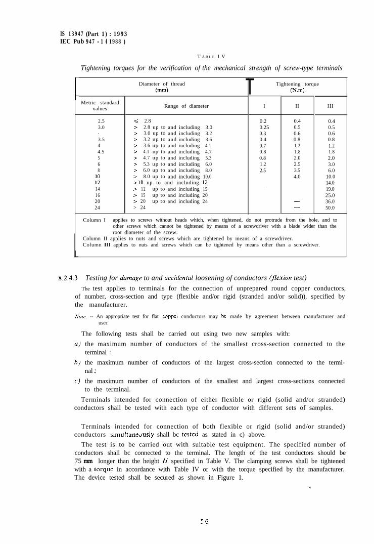
IS 13947 (Part 1) : 1993IEC Pub 947 - 1 ( 1988 )
C
L
T A B L E I V
Tightening torques for the verification of the mechanical strength of screw-type terminals
Metric standardvalues
2.53.0-3.544.5568
IOIi14162024
Diameter of thread(mm)
Range of diameter
< 2.8> 2.8 up to and including 3.0> 3.0 up to and including 3.2> 3.2 up to and including 3.6> 3.6 up to and including 4.1> 4.1 up to and including 4.7> 4.7 up to and including 5.3> 5.3 up to and including 6.0> 6.0 up to and including 8.0> 8.0 up to and including 10.0r IO up to and including 12> 12 up to and including 15> 15 up to and including 20> 20 up to and including 24> 24
I II III
0.2 0.40.25 0.50.3 0.60.4 0.80.7 1.20.8 1.80.8 2.01.2 3.02.5 6.0
10.014.0
0.40.50.60.81.21.82.02.53.54.0
- 19.025.036.050.0
---
Column I applies to screws without heads which, when tightened, do not protrude from the hole, and toother screws which cannot be tightened by means of a screwdriver with a blade wider than theroot diameter of the screw.
Column II applies to nuts and screws which are tightened by means of a screwdriver.Column III applies to nuts and screws which can be tightened by means other than a screwdriver.
T Tightening torquePW
8.2.4.3 Testing for dumuge to and uccidental loosening of conductors (‘exion test)
The test applies to terminals for the connection of unprepared round copper conductors,of number, cross-section and type (flexible and/or rigid (stranded and/or solid)), specified bythe manufacturer.
Note. -- An appropriate test for flat copper conductors may be made by agreement between manufacturer anduser.
The following tests shall be carried out using two new samples with:
the maximum number of conductors of the smallest cross-section connected to theterminal ;
the maximum number of conductors of the largest cross-section connected to the termi-nal ;
the maximum number of conductors of the smallest and largest cross-sections connectedto the terminal.
Terminals intended for connection of either flexible or rigid (solid and/or stranded)conductors shall be tested with each type of conductor with different sets of samples.
Terminals intended for connection of both flexible or rigid (solid and/or stranded)conductors simultane.4y shall bc tested as stated in c) above.
The test is to be carried out with suitable test equipment. The specified number ofconductors shall bc connected to the terminal. The length of the test conductors should be75 mm longer than the height H specified in Table V. The clamping screws shall be tightenedwith a torque in accordance with Table IV or with the torque specified by the manufacturer.The device tested shall be secured as shown in Figure 1.
c
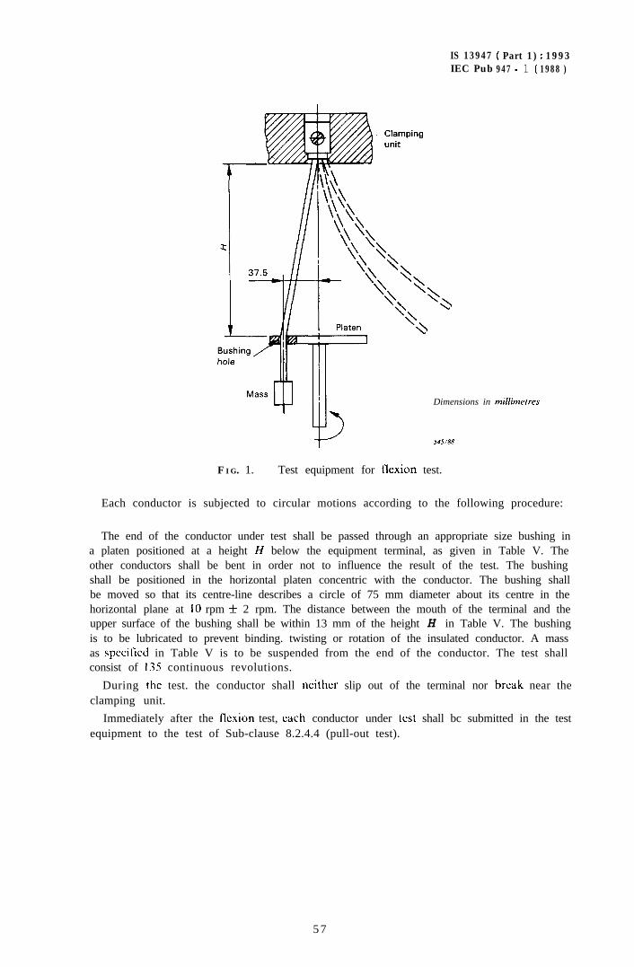
IS 13947 ( Part 1) : 1993IEC Pub 947 - 1 ( 1988 )
Dimensions in millimerres
F I G. 1. - Test equipment for flexion test.
Each conductor is subjected to circular motions according to the following procedure:
The end of the conductor under test shall be passed through an appropriate size bushing ina platen positioned at a height H below the equipment terminal, as given in Table V. Theother conductors shall be bent in order not to influence the result of the test. The bushingshall be positioned in the horizontal platen concentric with the conductor. The bushing shallbe moved so that its centre-line describes a circle of 75 mm diameter about its centre in thehorizontal plane at IO rpm ) 2 rpm. The distance between the mouth of the terminal and theupper surface of the bushing shall be within 13 mm of the height H in Table V. The bushingis to be lubricated to prevent binding. twisting or rotation of the insulated conductor. A massas specitied in Table V is to be suspended from the end of the conductor. The test shallconsist of I35 continuous revolutions.
During the test. the conductor shall neither slip out of the terminal nor break near theclamping unit.
Immediately after the flexion test, each conductor under test shall bc submitted in the testequipment to the test of Sub-clause 8.2.4.4 (pull-out test).
5 7
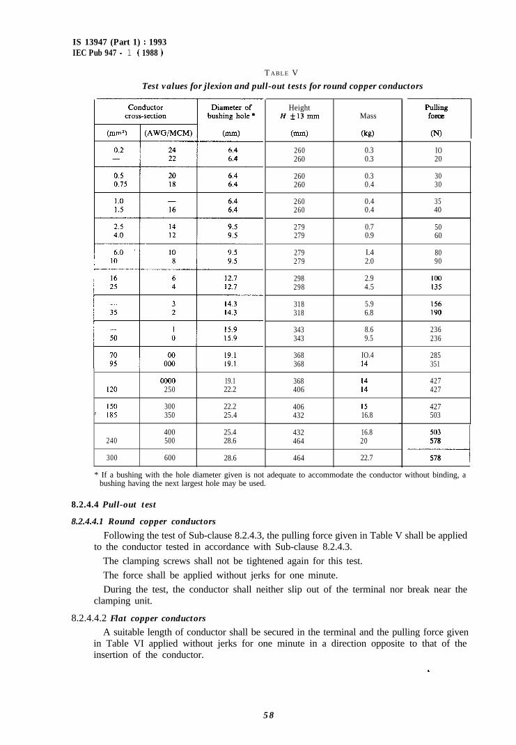
IS 13947 (Part 1) : 1993IEC Pub 947 - 1 ( 1988 )
T ABLE V
Test values for jlexion and pull-out tests for round copper conductors
HeightHf13mm
(mm)
260260
260260
260260
279279
279279
298298
318318
343343
368368
368406
406432
432464
464
Mass
(kg)
0.30.3
0.30.4
0.40.4
0.70.9
I.42.0
2.94.5
5.96.8
8.69.5
IO.4I4
I4I4
I516.8
16.820
22.7
PullingIforce
(NJ
0000 19.1120 250 22.2
150 300 22.2c I85 350 25.4
400 25.4240 500 28.6
300 600 28.6
IO20
3030
3540
5060
8090
100135
156190
236236
285351
427427
427503
503------A578
578
* If a bushing with the hole diameter given is not adequate to accommodate the conductor without binding, abushing having the next largest hole may be used.
8.2.4.4 Pull-out test
8.2.4.4.1 Round copper conductors
Following the test of Sub-clause 8.2.4.3, the pulling force given in Table V shall be appliedto the conductor tested in accordance with Sub-clause 8.2.4.3.
The clamping screws shall not be tightened again for this test.The force shall be applied without jerks for one minute.During the test, the conductor shall neither slip out of the terminal nor break near the
clamping unit.
8.2.4.4.2 Flat copper conductors
A suitable length of conductor shall be secured in the terminal and the pulling force givenin Table VI applied without jerks for one minute in a direction opposite to that of theinsertion of the conductor.
5 8
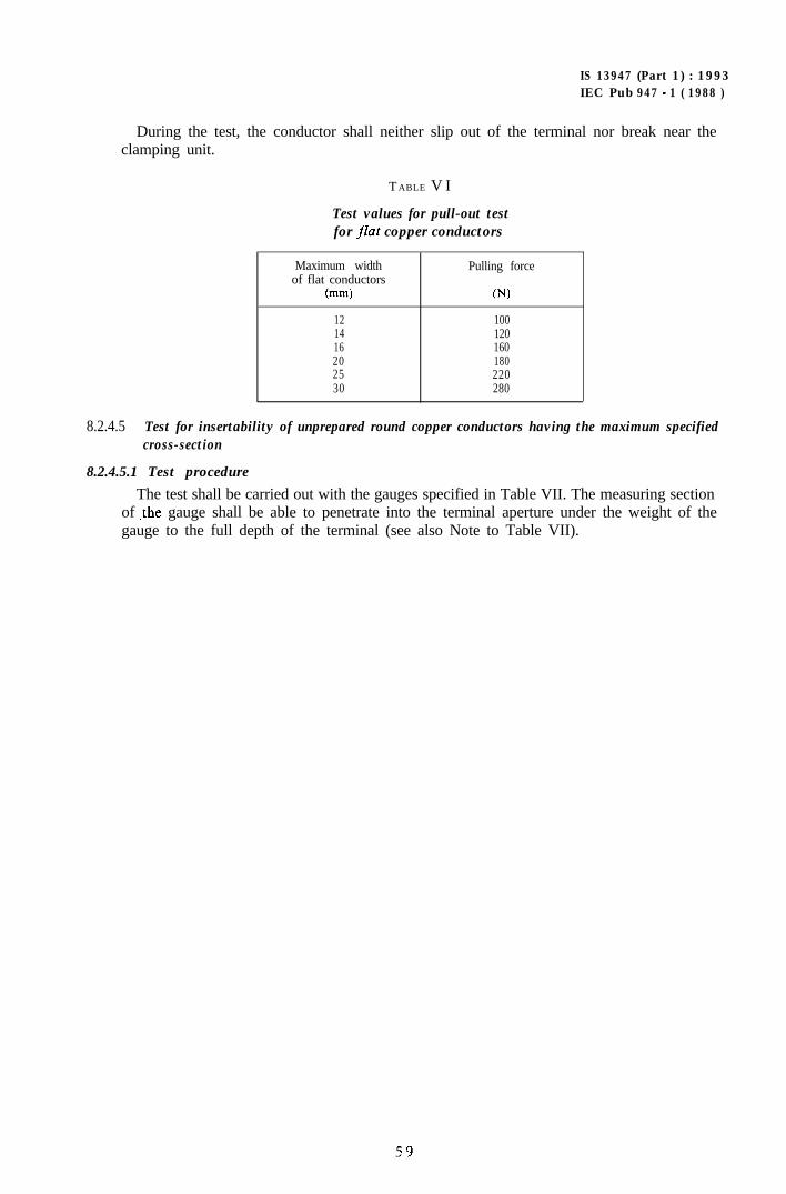
IS 13947 (Part 1) : 1993IEC Pub 947 - 1 ( 1988 )
During the test, the conductor shall neither slip out of the terminal nor break near theclamping unit.
T ABLE V I
Test values for pull-out testfor flat copper conductors
Maximum widthof flat conductors
(mm)
121416202530
Pulling force
WI
100120160180220280
8.2.4.5 Test for insertability of unprepared round copper conductors having the maximum specifiedcross-section
8.2.4.5.1 Test procedure
The test shall be carried out with the gauges specified in Table VII. The measuring sectionof ,the gauge shall be able to penetrate into the terminal aperture under the weight of thegauge to the full depth of the terminal (see also Note to Table VII).
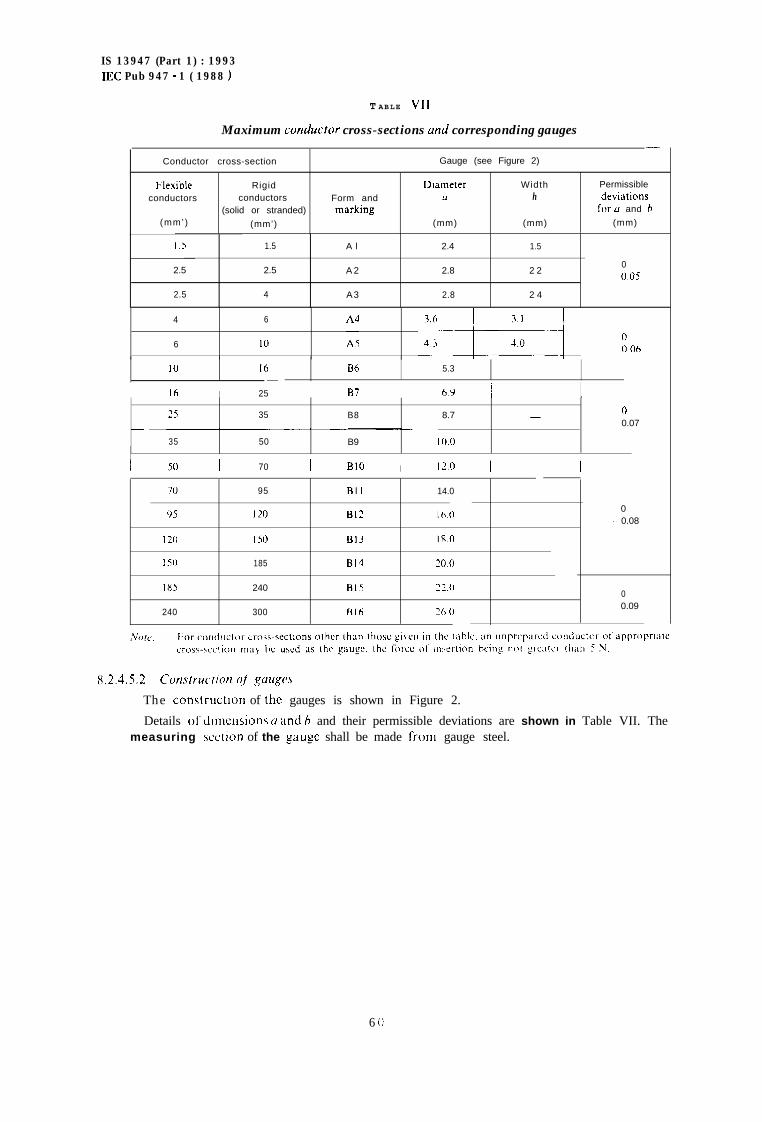
IS 13947 (Part 1) : 1993mc Pub 947 - 1 ( 1988 )
T ABLE VII
Maximum conducfor cross-sections und corresponding gauges-
Conductor cross-section Gauge (see Figure 2)
Flexible Rigid Diameter Width Permissible
conductors conductors Form and (1 h dewations
(solid or stranded) marking lor u and h
(mm’) (mm’) (mm) (mm) (mm)
1.5 1.5 A l 2.4 1.5
2.5 2.5 A 2 2.8 2 200.05
2.5 4 A3 2.8 2 4
4 6
6 IO :‘, G-j--+ :).06
1u I6 Bh 5.3-
I I6 I 25 I I37 6Y I
25 35 B8 8.7 0-0.07~_.
35 50 B9 IO.0
I 50 I 70 I BIO I 12.0 I I
70 95 Bll 14.0
Y5 I20 812 16.00
- 0.08
I20 IS0 Bl3 180
I50 185 814 20.0
IX5 240 RI5 22.00
240 300 Blfi 20 tJ0.09
8.2.4.5.2 C~wutrui~Iv31 qf gauges
The construction of the gauges is shown in Figure 2.
Details ol‘dtmcnsions (I and h and their permissible deviations are shown in Table VII. Themeasuring xction of the gauge shall be made from gauge steel.
6 C)
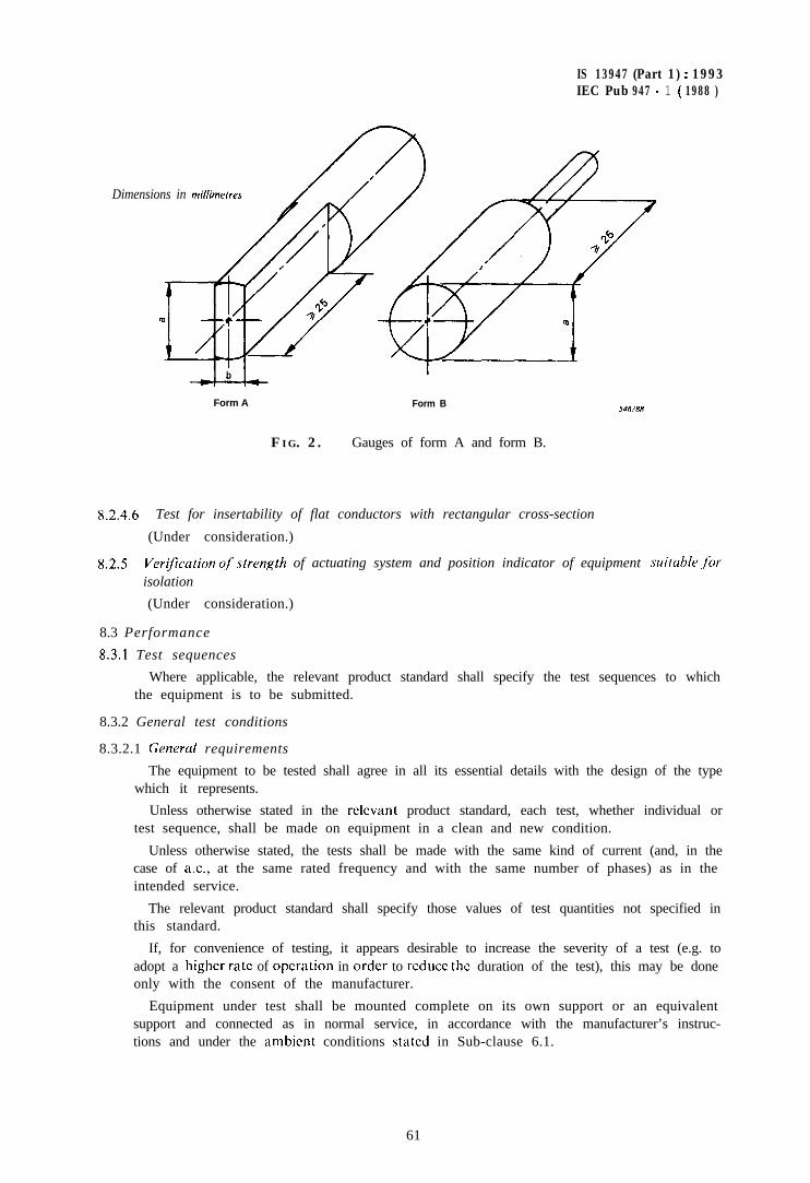
IS 13947 (Part 1) : 1993IEC Pub 947 - 1 ( 1988 )
Dimensions in millimetres
b
Form A Form B546/88
F IG. 2. - Gauges of form A and form B.
8.2.4.6 Test for insertability of flat conductors with rectangular cross-section
(Under consideration.)
8.2.5 VeriJi’cation ofstrength of actuating system and position indicator of equipment .suituhle .forisolation
(Under consideration.)
8.3 Performance
8.3.1 Test sequences
Where applicable, the relevant product standard shall specify the test sequences to whichthe equipment is to be submitted.
8.3.2 General test conditions
8.3.2.1 Generul requirements
The equipment to be tested shall agree in all its essential details with the design of the typewhich it represents.
Unless otherwise stated in the relevant product standard, each test, whether individual ortest sequence, shall be made on equipment in a clean and new condition.
Unless otherwise stated, the tests shall be made with the same kind of current (and, in thecase of a.c., at the same rated frequency and with the same number of phases) as in theintended service.
The relevant product standard shall specify those values of test quantities not specified inthis standard.
If, for convenience of testing, it appears desirable to increase the severity of a test (e.g. toadopt a higher rate of operation in order to rcducc the duration of the test), this may be doneonly with the consent of the manufacturer.
Equipment under test shall be mounted complete on its own support or an equivalentsupport and connected as in normal service, in accordance with the manufacturer’s instruc-tions and under the ambient conditions stated in Sub-clause 6.1.
61
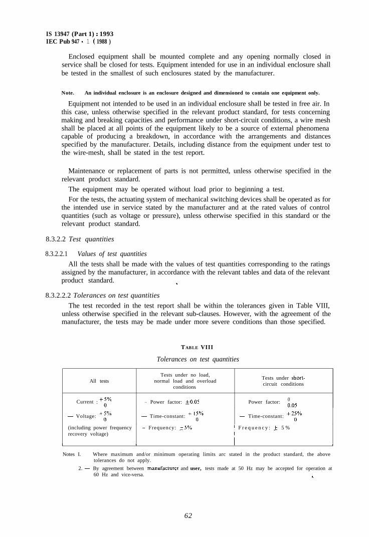
IS 13947 (Part 1) : 1993IEC Pub 947 - 1 ( 1988 )
Enclosed equipment shall be mounted complete and any opening normally closed inservice shall be closed for tests. Equipment intended for use in an individual enclosure shallbe tested in the smallest of such enclosures stated by the manufacturer.
Note. - An individual enclosure is an enclosure designed and dimensioned to contain one equipment only.
Equipment not intended to be used in an individual enclosure shall be tested in free air. Inthis case, unless otherwise specified in the relevant product standard, for tests concerningmaking and breaking capacities and performance under short-circuit conditions, a wire meshshall be placed at all points of the equipment likely to be a source of external phenomenacapable of producing a breakdown, in accordance with the arrangements and distancesspecified by the manufacturer. Details, including distance from the equipment under test tothe wire-mesh, shall be stated in the test report.
Maintenance or replacement of parts is not permitted, unless otherwise specified in therelevant product standard.
The equipment may be operated without load prior to beginning a test.For the tests, the actuating system of mechanical switching devices shall be operated as for
the intended use in service stated by the manufacturer and at the rated values of controlquantities (such as voltage or pressure), unless otherwise specified in this standard or therelevant product standard.
8.3.2.2 Test quantities
8.3.2.2.1 Values of test quantities
All the tests shall be made with the values of test quantities corresponding to the ratingsassigned by the manufacturer, in accordance with the relevant tables and data of the relevantproduct standard. 3
8.3.2.2.2 Tolerances on test quantities
The test recorded in the test report shall be within the tolerances given in Table VIII,unless otherwise specified in the relevant sub-clauses. However, with the agreement of themanufacturer, the tests may be made under more severe conditions than those specified.
TABLE VIII
Tolerances on test quantities
All tests
- Current : +:%
Tests under no load,normal load and overload
conditions
- Power factor: +0.05
Tests under short-circuit conditions
0- Power factor: _ o,05
~ Voltage: +(:% - Time-constant: + ‘i” - Time-constant: “i%
(including power frequency ~- Frequency: +5% ! F r e q u e n c y : f 5 %recovery voltage)
II I I I
Notes I. ~ Where maximum and/or minimum operating limits arc stated in the product standard, the abovetolerances do not apply.
2. - By agreement between manufActurer and user, tests made at 50 Hz may be accepted for operation at60 Hz and vice-versa. *
62
IS 13947 (Part 1) : 1993IEC Pub 947 - 1 ( 1988 )
8.3.2.2.3 Recovery voltage
a) Power-frequency recovery voltage
For all breaking capacity and short-circuit breaking capacity tests, the value of thepower-frequency recovery voltage shall be 1.05 times the value of the rated operationalvoltage as assigned by the manufacturer or as specified in the relevant product stan-dard.Notes 1. - The value of 1.05 times the rated operational voltage for the power-frequency recovery voltage is
deemed to cover the effects of the variations of the system voltage under normal service condi-tions.
2. - This may require that the applied voltage be increased but the prospective peak making currentshould not be exceeded without the consent of the manufacturer.
3. - The upper limit of the power-frequency recovery voltage may be increased with the approval ofthe manufacturer (see Sub-clause 8.3.2.2.2).
b) Transient recovery voltage
Transient recovery voltages, where required in the relevant product standard, aredetermined according to Sub-clause 8.3.3.5.2.
8.3.2.3 Evaluation of test results
Behaviour of the equipment during the tests and its condition after the tests shall bespecified in the relevant product standard. For short-circuit tests, see also Sub-clauses8.3.4.1.7 and 8.3.4.1.9.
0.3.2.4 Test reportsWritten reports on type tests proving compliance with the relevant product standard shall
be made available by the manufacturer. The details of test arrangements such as type andsize of the enclosure, if any, size of conductors, distance from the live parts to the enclosureor to parts normally earthed in service, method of operation of the actuating system, etc.,shall be given in the test report.
Test values and parameters shall form part of the test report.
8.3.3 Performance under no load, normal load and overload conditions
8.3.3.1 OperationTests shall be made to verify that the equipment operates correctly according to the
requirements of Sub-clause 7.2.1.1.
8.3.3.2 Operating limits
8.3.3.2.1 Po\c,er operated equipment
It shall be verified that the equipment opens and closes correctly within the limiting valuesof the control quantities. such as voltage, current, air pressure and temperatures, specified inthe relevant product standard. Tests are made with no current flowing through the maincircuit, unless otherwise specified.
8.3.3.2.2 Relays and releasesThe operating limits of relays and releases shall comply with the rcquircmcnts of Sub-
clauses 7.2.1.3, 7.2.1.4 and 7.2.1.5 and shall be verified according to the test proceduredefined in the relevant product standard.
For undervoltage relays and releases, see Sub-clause 7.2.1.3.For shunt releases, see Sub-clause 7.2. I .4.For current operated relays and releases, see Sub-clause 7.2.1.5.
63
IS 13947 4 Part 1) : 1993IEC Pub 947 - 1 ( 1988 )
8.3.3.3 Temperature-rise
8.3.3.3.1 Ambient air temperature
The ambient air temperature shall be recorded during the last quarter of the test period byat least two temperature sensing means, e.g. thermometers or thermocouples, equally distri-buted around the equipment at about half its height and at a distance of about 1 m from theequipment. The temperature sensing means shall be protected against air currents, heatradiation and indicating errors due to rapid temperature changes.
During the tests, the ambient air temperature shall be between + 10 “C and +40 “C andshall not vary by more than 10 K.
However, if the variation of the ambient air temperature exceeds 3 K, an appropriatecorrection factor should be applied to the measured temperature of the parts, depending onthe thermal time-constant of the equipment.
8.3.3.3.2 Measurement of the temperature of parts
For parts other than coils, the temperature of the different parts shall be measured bysuitable temperature sensing means at those points most likely to attain the maximumtemperature ; these points shall be stated in the test report.
The oil temperature of oil-immersed equipment shall be measured at the upper part of theoil; this measurement may be made by means of a thermometer.
The temperature sensing means shall not significantly affect the temperature-rise.Good thermal conductivity between the temperature sensing means and the surface of the
part under test shall be ensured.For electromagnet coils, the method of measuring the temperature by variation of resis-
tance shall generally be used. Other methods are permitted only if it is impracticable to usethe resistance method.
The temperature of the coils before beginning the test shall not differ from that of thesurrounding medium by more than 3 K.
For copper conductors, the value of the hot temperature T, may be obtained from thevalue of the cold temperature T, as a function of the ratio of the hot resistance R, to the coldresistance R, by the following formula:
T, = 2 (T, + 234.5) - 234.5I
where T, and T, are expressed in degrees Celsius.
The test shall be made for a time sufficient for the temperature-rise to reach a steady-statevalue, but not exceeding 8 h. It is assumed that a steady-state is reached when the variationdoes not exceed 1 K per hour.
8.3.3.3.3 Temperature-rise of a part
The temperature-rise of a part is the difference between the temperature of the partmeasured in accordance with Sub-clause 8.3.3.3.2 and the ambient air temperature measuredin accordance with Sub-clause 8.3.3.3.1.
8.3.3.3.4 Temperature-rise of the main circuit
The equipment shall be mounted as specified in Sub-clause 8.3.2.1 and shall be protectedagainst abnormal external heating or cooling.
IS 13947 (Part 1) : 1993IEC Pub 947.1( 1988 )
Equipment having an integral enclosure and equipment only intended for use with aspecified type of enclosure shall be tested in its enclosure for the conventional thermalcurrent test. No opening giving false ventilation shall be allowed.
Equipment intended for use with more than one type of enclosure shall be tested either inthe smallest enclosure stated by the manufacturer to be suitable or tested without anenclosure. If tested without an enclosure the mafiufacturer shall be prepared to state a valueof conventional enclosed thermal current (see Sub-clause 4.3.2.2).
For tests with multiphase currents, the current shall be balanced in each phase withinf5%, and the average of these currents shall be not less than the appropriate testcurrent.
Unless otherwise specified in the relevant product standard, the temperature-rise test of themain circuit is made at one or both of the conventional thermal currents, as defined inSub-clauses 4.3.2.1 and 4.3.2.2 and may be made at any convenient voltage.
When the heat exchange between the main circuit, the control circuit and the auxiliarycircuits may be of significance, the temperature-rise tests stated in Sub-clauses 8.3,3.3.4,8.3.3.3.5, 8.3.3.3.6 and 8.3.3.3.7 shall be made simultaneously, in so far as this is allowed bythe relevant product standard.
Tests on d.c. rated equipment may be made with an a.c. supply for convenience of testing,but only with the consent of the manufacturer.
In the case of multipole equipment fitted with identical poles and tested with a.c. the testmay be carried out, but subject to the manufacturer’s agreement, with single-phase currentwith all poles connected in series provided that magnetic effects can be neglected.
In the case of three-pole equipment provided with a neutral pole different from the phasepoles, the test shall comprise:
- a three-phase test on the three identical poles,- a single-phase test on the neutral pole connected in series with the adjacent pole, the value
of the test quantities being dctcrmined according to the value of the conventional thermalcurrent of the neutral pole (see Sub-clause 7.1.8).
Equipment provided with short-circuit-protective devices shall be tested according to therequirements given in the relevant product standard.
At the end of the test, the temperature-rise of the different parts of the main circuit shallnot exceed the values given in Tables II and JJJ, unless otherwise specified in the relevantproduct standard.
Depending on the value or the conventional thermal current, one of the following testconnection arrangements shall be used:
i) For v~11u~~.s of tc.~t currcnf up to und including 400 A
cr) The connections shall bc single-core, PVC insulated, copper conductors with cross-sections as given in Table IX.
h) The connections shall be in free air, and spaced at approximately the distance existingbctwcen the terminals.
C) For single-phase or multi-phase tests the minimum length of any temporary connec-tion from an equipment terminal to another terminal or to the test supply or to a starpoint shall be:
1 m for cross-sections up to and including 35 mm* (or AWG 2);- 2 m for cross-sections larger than 35 mm2 (or AWG 2).
65
IS 13947 (Part 1) : 1993IEC Pub 947 - 1 ( 1988 )
ii) For values of test current
a) The connections shallhigher than 400 A but not exceeding 8@0 A:
be single-core, PVC insulated, copper conductors with cross-sectional areas as given in Table X, or the equivalent copper bars given in Table XI,as recommended by the manufacturer.
b) The connections specified in a) shall be spaced at approxima&y the same distance asthat between the terminals. Copper bars shall be painted matt black. Multiple parallelconductors per terminal shall be bunched together and arranged with approximately10 mm air space between each other. Multiple copper -bars per terminal shall bespaced at a distance approximately equal to the bar thickness. If the sizes stated forthe bars are not suitable for the terminals, or arenot available, other bars havingapproximately the same cross-sections and approximately the same or smaller coolingareas may be used. Copper conductors or bars shall not be laminated.
C) For single-phase or multi-phase tests the minimum length of any temporary connec-tion from the equipment terminal to another terminal or to the test supply shall be2 m. The minimum length to a star point may be reduced to 1.2 m
iii) For values of test current higher than 800 A but not exceeding 3 I50 A:
a) The connections shall be copper bars of the sizes stated in Table XI, unless theequipment is designed only for cable connection. In this case, the size and arrange-ment of the cables shall be as specified by the manufacturer.
6) Copper bars shall be spaced at approximately the same distance as that between theterminals. Copper bars shall be painted matt black. Multiple copper bars per terminalshall be spaced at a distance approximately equal to the bar thickness. If the sizesstated for the bars are not suitable for the terminals, or are not available, other barshaving approximately the sameshall not be laminated.
or smaller cooling areas may be used. Copper bars
c) For single-phase or multi-phase tests the minimum length of any temporary connec-tion from an equipment terminal to another terminal or to the supply shall be 3 m,but this can be reduced to 2 m provided that the temperature-rise at the supply end ofthe connection is not more than 5 K below the temperature-rise in the middle of theconnection length. The minimum length to a star point shall be 2 m.
iv) For values of test current higher than 3 150 A:
Agreement shall be reached bctwecn manufacturer and user on all relevant items of thetest, such as: type of supply, number of phases and frequency (where applicable),cross-sections of test connections. etc. This information shall form part of the testreport.
6 6
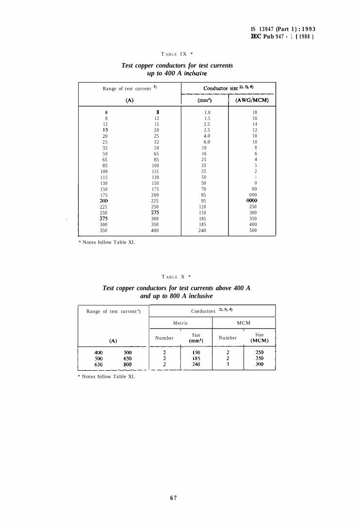
IS 13947 (Part 1) : 1993IEC Pub 947 - 1 ( 1988 )
T ABLE IX *
Test copper conductors for test currentsup to 400 A irklusive
Range of test current ‘)
0 8 1.0 188 12 1.5 16
12 15 2.5 1415 20 2.5 1220 25 4.0 1025 32 6.0 1032 50 10 850 65 16 665 85 25 485 100 35 3
100 115 35 2115 130 50 1130 150 50 0150 175 70 00175 200 95 000200 225 95 0000225 250 120 250250 215 150 300215 300 185 350300 350 185 400350 400 240 500
* Notes follow Table XI.
T ABLE X *
Test copper conductors for test currents above 400 Aand up to 800 A inclusive
Range of test current“) Conductors 2)* 3), 4,
(A)
1* Notes follow Table XI.
Metric1
MCMI ,
Number Size
INumber
Size(mm*) (MCM) I
67
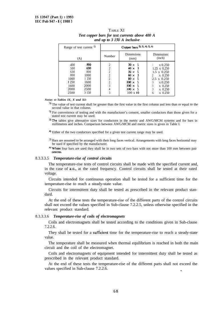
IS 13947 (Part 1) : 1993IEC Pub 947 - 1( 1988 )
TABLE XITest copper bars for test currents above 400 A
and up to 3 I50 A inclusive
Range of test current *) Copper bars 2). 3). 4). 5). 6)
(A)
400500 ::630 800800 1000
1000 1 2501 250 16001600 20002000 25002500 3 150
LNotes IO Tables IX, X and XI:
Number Dimensions Dimensions(mm) (inch)
2 30x 5 1 x 0.2502 40x 5 1.25 x 0.2502 50x 5 1.5 x 0.2502 60x 5 2 x 0.2502 80x 5 2.5 x 0.2502 100x 5 3 x 0.2503 100x 5 3 x 0.2504 100x 5 3 x 0.2503 100 x 10 6 x 0.250
‘) The value of test current shall be greater than the first value in the first column and less than or equal to thesecond value in that column.
2, For convenience of testing and with the manufacturer’s consent, smaller conductors than those given for astated test current may be used.
‘)The tables give alternative sizes for conductors in the metric and AWG/MCM systems and for bars inmillimetres and inches. Comparison between AWG/MCM and metric sizes is given in Table I.
4, Either of the two conductors specified for a given test current range may be used.
5, Bars are assumed to be arranged with their long faces vertical. Arrangements with long faces horizontal maybe used if specified by the manufacturer.
@Where four bars are used they shall be in two sets of two bars with not more than 100 mm between paircentres.
8.3.3.3.5 Temperature-rise of control circuitsThe temperature-rise tests of control circuits shall be made with the specified current and,
in the case of a.c., at the rated frequency. Control circuits shall be tested at their ratedvoltage.
Circuits intended for continuous operation shall be tested for a sufficient time for thetemperature-rise to reach a steady-state value.
Circuits for intermittent duty shall be tested as prescribed in the relevant product stan-dard.
At the end of these tests the temperature-rise of the different parts of the control circuitsshall not exceed the values specified in Sub-clause 7.2.2.5, unless otherwise specified in therelevant product standard.
8.3.3.3.6 Temperature-rise of coils of electromagnetsCoils and electromagnets shall be tested according to the conditions given in Sub-clause
7.2.2.6.
They shall be tested for a suffkient time for the temperature-rise to reach a steady-statevalue.
The temperature shall be measured when thermal equilibrium is reached in both the maincircuit and the coil of the electromagnet.
Coils and electromagnets of equipment intended for intermittent duty shall be tested asprescribed in the relevant product standard.
At the end of these tests the temperature-rise of the different parts shall not exceed thevalues specified in Sub-clause 7.2.2.6. (r
68
IS 13947 (Part 1) : 1993IEC Pub 947 - 1 ( 1988 )
8.3.3.3.1 Temperature-rise of auxiliary circuits
The temperature-rise tests of auxiliary circuits shall be made under the same conditions asthose specified in Sub-clause 8.3.3.3.5, but may be carried out at any convenient voltage.
At the end of these tests the temperature-rise of the auxiliary circuits shall not exceed thevalues specified in Sub-clause 7.2.2.7
3.3.3.4 Dielectric properties
The test requirements specified in Sub-clauses 8.3.3.4.1 to 8.313.4.3 apply to equipment forwhich the manufacturer has declared a value for the rated impulse withstand voltage Ulmp(see Sub-clause 4.3.1.3) assigned according to Sub-clause 7.2.3.
In the other cases, the test requirements of the relevant product standard shall apply.
8.3.3.4.1 T~)pe tests
1) General conditions
The equipment to be tested shall comply with the general requirements of Sub-clause8.3.2.1. Moreover, if it is to be used without an enclosure, it shall be mounted on a metalplate and all exposed conductive parts (frame, etc.) which are earthed in normal serviceshall be connected to the metal plate.
Any actuator of insulating material and any integral non-metallic enclosure of equip-ment intended to be used without additional enclosure shall be covered by a metal foiland connected to the frame or the mounting plate. The foil shall be applied to all surfaceswhere these can be touched with the standard test finger.
2) Verification of impulse withstand voltages (clearunces rend assoricrted solid insulation)
Equipment shall comply with the requirements stated in Sub-clauses 7.2.3.1 and7.2.3.2.
The verification of clearances and associated solid insulation is made by a test at therated impulse withstand voltage.
Clearances equal to or larger than the values of Case A of Table XIII may be verifiedby measurement, according to the method described in Appendix G.
There shall be no unintentional disruptive discharge during the tests.
Nnrcr I, An exception is an intenttonal disruptive discharge. e.g. by transient overvoltage suppressingtllCiil?S.
2. - The term “dtsruptlvc discharge” relates to phenomena associated with the failure of msulationunder clcctrtcal stress. in which the discharge completely bridges the insulation under test, reducingthe voltage between the clcctrodcs to zero or nearly IO Tero.
3. The term “sparkover” IS used when a disruptive dlscharge occurs in a gaseous or liquid dielec-lric
4. The term “f&hover” IS used when a disruptive discharge occurs over the surface of a dielectric in aga~cous or hquld medium.
.r ‘1‘1~ term “puncture” IS used when a disruptive discharge occurs through a solid dielectric.
6 --- A dlsruptlvc d~har~c in a solid dlclectric products permanent IOX’I o f dielectric stlcngth; in ;iII~UKI or gazet~ua diclcctric, the loss may hc only temporary.
The test voltage shall be that specified m Sub-clauses 7.2.3.1 and 7.2.3.2
69
IS 13947 (Part 1) : 1993IEC Pub 947 - 1 ( 1988 )
With the manufacturer’s agreement, the test may be carried out using power frequencyor d.c. voltage as given in Table XII. However, equipment incorporating overvoltagesuppressing means shall be tested with an impulse voltage. The energy content of the testcurrent shall not exceed the energy rating of the overvoltage suppressing means.
Note. - The rating of the suppressing means should be suitable for the application. Such ratings are under
4
b)
cl
consideration.__
The 1.2/50 ps impulse voltage shall be applied 3 times for each polarity at intervals of1 s minimum.Power frequency and d.c. voltage shall be applied during 3 cycles in the case of ac., or10 ms for each polarity in the case of d.c.
If, in the course of a test procedure, repeated dielectric testing is required, the relevantproduct standard shall state the dielectric test conditions.
Note. - An example of test equipment is under consideration.
4) Application of test voltage
With the equipment mounted and prepared as specified in item 1) above, the testvoltage is applied as follows:
4
b)
cl
4
Between all the terminals of the main circuit connected together (including the controland auxiliary circuits connected to the main circuit) and the enclosure or mountingplate, with the contacts in all normal positions of operation.
Between each pole of the main circuit and the other poles connected together and tothe enclosure or mounting plate, with the contacts in all normal positions of oper-ation.Between each control and auxiliary circuit not normally connected to the main circuitand :- the main circuit,- the other circuits,- the exposed conductive parts,- the enclosure or mounting plate,which, wherever appropriate, may be connected together.For equipment suitable for isolation, across the poles of the main circuit, the lineterminals being connected together and the load terminals connected together.
The test voltage shall be applied between the line and load terminals of theequipment with the contacts in the open position and its value shall be as specified inSub-clause 7.2.3.1 b).
For equipment not suitable for isolation, the requirements for testing with thecontacts in the open position shall be stated in the relevant product standard.
5) Verification of creepage distances
The shortest creepage distances between phases, between circuit conductors at differentvoltages and live and exposed conductive parts shall be measured. The measured creepagedistance with respect to Material Group and pollution degree shall comply with therequirements of Sub-clause 1.2.3.4.
70
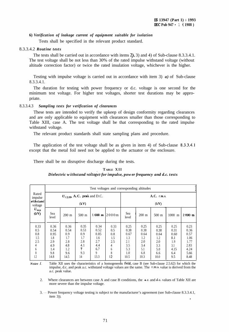
Is 13947 (Part 1) : 1993IEC Pub 947 - 1 ( 1988 )
6) Verification of leakage current of equipment suitable for isolation
Tests shall be specified in the relevant product standard.
8.3.3.4.2 Routine testsThe tests shall be carried out in accordance with items 2,) 3) and 4) of Sub-clause 8.3.3.4.1.
The test voltage shall be not less than 30% of the rated impulse withstand voltage (withoutaltitude correction factor) or twice the rated insulation voltage, whichever is the higher.
Testing with impulse voltage is carried out in accordance with item 3) a) of Sub-clause8.3.3.4.1.
The duration for testing with power frequency or d.c. voltage is one second for theminimum test voltage. For higher test voltages, shorter test durations may be appro-priate.
8.3.3.4.3 Sampling tests for verification of clearances
These tests are intended to verify the upkeep of design conformity regarding clearancesand are only applicable to equipment with clearances smaller than those corresponding toTable XIII, case A. The test voltage shall be that corresponding to the rated impulsewithstand voltage.
The relevant product standards shall state sampling plans and procedure.
The application of the test voltage shall be as given in item 4) of Sub-clause 8.3.3.4.1except that the metal foil need not be applied to the actuator or the enclosure.
There shall be no disruptive discharge during the tests.
Ratedimpulse
withstanvoltage
r/imp
(kV)
0.330.50.81.52.5468
12
Nores I.
d
TABLE XIIDielectric withstand voltagis for impulse, power frequency and d.c. tests
Test voltages and corresponding altitudes
SealevelV
0.360.540.951.82.94.91.49.8
14.8
L1,,2,5,,, A.C. peak and D.C. A.C. r.m.s.
200 m
0.36 0.35 0.34 0.33 0.25 0.25 0.25 0.25 0.230.54 0.53 0.52 0.5 0.38 0.38 0.38 0.31 0.360.9 0.9 0.85 0.8 0.67 0.64 0.64 0.60 0.571.7 1.7 1.6 1.5 1.3 1.2 1.2 I.1 1.062.8 2.8 2.7 2.5 2.1 2.0 2.0 1.9 1.774.8 4.1 4.4 4 3.5 3.4 3.3 3.1 2.831.2 I 6.7 6 5.3 5.1 5.0 4.15 4.249.6 9.3 9 8 1.0 6.8 6.6 6.4 5.66
14.5 14 13.3 I2 10.5 10.3 10.0 9.5 8.48
@VI
500 m IOOOm 2 0 0 0 m
@VI1
Sealevel
I I200 m 500 m 1000 m 2OOOm
1
Table XII uses the characteristics of a homogeneous field, case B (see Sub-clause 2.5.62) for which theimpulse, d.c. and peak a.c. withstand voltage values are the same. The r.m.s. value is derived from thea.c. peak value.
2. - Where clearances are between case A and case B conditions, the a.c. and dc. values of Table XII aremore severe than the impulse voltage.
,
3. - Power frequency voltage testing is subject to the manufacturer’s agreement (see Sub-clause 8.3.3.4.1,item 3)). .
71
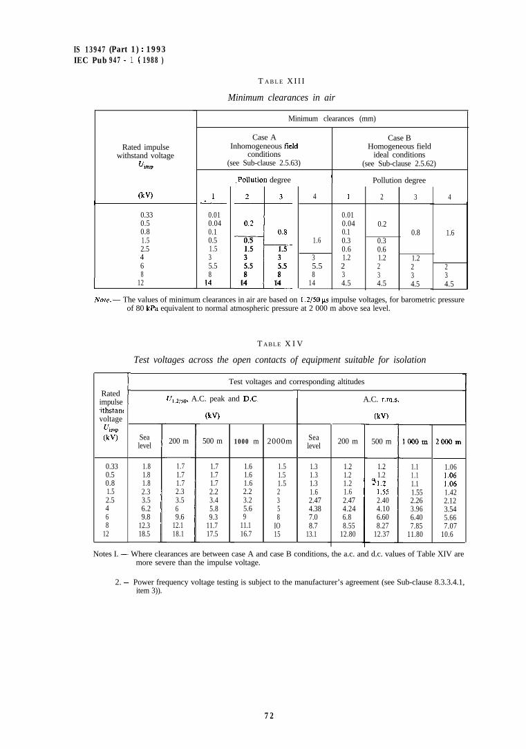
IS 13947 (Part 1) : 1993IEC Pub 947 - 1 ( 1988 )
T A B L E X I I I
Minimum clearances in air
Minimum clearances (mm)
Case A Case BInhomogeneous field
conditionsHomogeneous field
ideal conditions(see Sub-clause 2.5.63) (see Sub-clause 2.5.62)
Rated impulsewithstand voltage
Uimp
(kV)
.Pollution degree I Pollution degree
2 3
0.20.830.5
1.5 1.53 35.5 5.58 8
14 14
I+
0.010.040.10.51.535.58
14
4 I 2 3
0.010.04 0.20.1 0.8
1.6 0.3 0.30.6 0.6
3 1.2 1.2 1.25.5 2 2 28 3 3 3
14 4.5 4.5 4.5
4
0.330.50.81.52.5468
1.6
234.5I 12
Note. - The values of minimum clearances in air are based on I .2/50 ns impulse voltages, for barometric pressureof 80 kPa equivalent to normal atmospheric pressure at 2 000 m above sea level.
T ABLE X I V
Test voltages across the open contacts of equipment suitable for isolation
f
Test voltages and corresponding altitudes
Ratedimpulseithstancvoltage
fJimp(kV) Sea
level
0.33 1.80.5 1.80.8 1.81.5 2.32.5 3.54 6.26 9.88 12.3
12 18.5
TU,,,,sO, A.C. peak and DC. A.C. r.m.s.
(kv) (kv)
500 m
1.21.2
‘!I.2I .552.404.106.608.27
12.37
500 m 1000 m 2000m Sealevel 200 m
1.7 1.6 1.5 1.3 1.21.7 1.6 1.5 1.3 1.21.7 1.6 1.5 1.3 1.22.2 2.2 2 1.6 1.63.4 3.2 3 2.47 2.475.8 5.6 5 4.38 4.249.3 9 8 7.0 6.8
11.7 11.1 IO 8.7 8.5517.5 16.7 15 13.1 12.80
200 m
1.71.71.72.33.569.6
12.118.1
1OOOm 2OOOm
1.1 1.061.1 I .061.1 I .061.55 1.422.26 2.123.96 3.546.40 5.667.85 7.07
11.80 10.6
Notes I. - Where clearances are between case A and case B conditions, the a.c. and d.c. values of Table XIV aremore severe than the impulse voltage.
2. - Power frequency voltage testing is subject to the manufacturer’s agreement (see Sub-clause 8.3.3.4.1,item 3)).
72
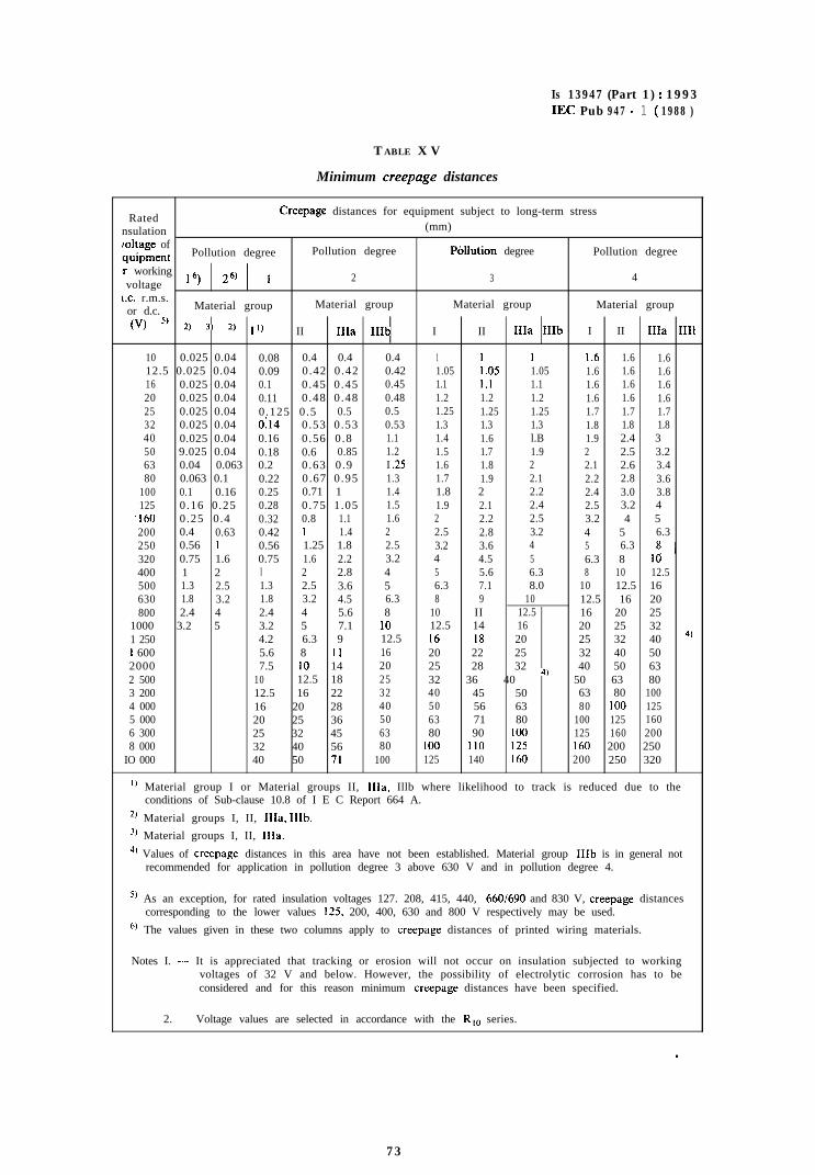
Is 13947 (Part 1) : 1993IJW Pub 947 - 1 ( 1988 )
TABLE X V
Minimum creepage distances
RatedCreepage distances for equipment subject to long-term stress
nsulation (mm)
toltage of:quipment Pollution degree Pollution degree Pbllution degree Pollution degree
lr workingvoltage 16) 26) 1 2 3 4
L.C. r.m.s.or d.c. Material group Material group Material group Material group
(“) 5, *) 3, *) I’) II IIIa IIIb I II IIIa IIIb I II IIIa IIIt
10 0.025 0.04 0.08 0.4 0.4 0.4 1 1 1 1.6 1.6 1.612.5 0.025 0.04 0.09 0.42 0.42 0.42 1.05 1.05 1.05 1.6 1.6 1.616 0.025 0.04 0.1 0.45 0.45 0.45 1.1 1.1 1.1 1.6 1.6 1.620 0.025 0.04 0.11 0.48 0.48 0.48 1.2 1.2 1.2 1.6 1.6 1.625 0.025 0.04 0.125 0.5 0.5 0.5 1.25 1.25 1.25 1.7 1.7 1.732 0.025 0.04 0:14 0.53 0.53 0.53 1.3 1.3 1.3 1.8 1.8 1.840 0.025 0.04 0.16 0.56 0.8 1.1 1.4 1.6 l.B 1.9 2.4 350 9.025 0.04 0.18 0.6 0.85 1.2 1.5 1.7 1.9 2 2.5 3.263 0.04 0.063 0.2 0.63 0.9 I .25 1.6 1.8 2 2.1 2.6 3.480 0.063 0.1 0.22 0.67 0.95 1.3 1.7 1.9 2.1 2.2 2.8 3.6
100 0.1 0.16 0.25 0.71 1 1.4 1.8 2 2.2 2.4 3.0 3.8125 0.16 0.25 0.28 0.75 1.05 1.5 1.9 2.1 2.4 2.5 3.2 4
‘160 0.25 0.4 0.32 0.8 1.1 1.6 2 2.2 2.5 3.2 4 5200 0.4 0.63 0.42 I 1.4 2 2.5 2.8 3.2 4 5 6.3250 0.56 1 0.56 1.25 1.8 2.5 3.2 3.6 4 5 6.3320 0.75 1.6 0.75 1.6 2.2 3.2 4 4.5 5 6.3 8 1: ’400 1 2 I 2 2.8 4 5 5.6 6.3 8 10 12.5500 1.3 2.5 1.3 2.5 3.6 5 6.3 7.1 8.0 10 12.5 16630 1.8 3.2 1.8 3.2 4.5 6.3 8 9 10 12.5 16 20800 2.4 4 2.4 4 5.6 8 10 II 12.5 16 20 25
1000 3.2 5 3.2 5 7.1 10 12.5 14 16 20 25 321 250 4.2 6.3 9 12.5 16 18 20 25 32 40 4,1 600 5.6 8 II 16 20 22 25 32 40 502000 7.5 10 14 20 25 28 32 40 50 632 500 10 12.5 18 25 32 36 40 4, 50 63 803 200 12.5 16 22 32 40 45 50 63 80 1004 000 16 20 28 40 50 56 63 80 100 1255 000 20 25 36 50 63 71 80 100 125 1606 300 25 32 45 63 80 90 100 125 160 2008 000 32 40 56 80 100 110 125 I60 200 250
IO 000 40 50 71 100 125 140 I60 200 250 320
‘) Material group I or Material groups II, IIIa, Illb where likelihood to track is reduced due to theconditions of Sub-clause 10.8 of I E C Report 664 A.
2J Material groups I, II, IIIa, IIIb.
j) Material groups I, II, IIIa.
4’ Values of creepage distances in this area have not been established. Material group IIIb is in general notrecommended for application in pollution degree 3 above 630 V and in pollution degree 4.
5, As an exception, for rated insulation voltages 127. 208, 415, 440, 660/690 and 830 V, creepage distancescorresponding to the lower values 125. 200, 400, 630 and 800 V respectively may be used.
6, The values given in these two columns apply to creepage distances of printed wiring materials.
Notes I. -..- It is appreciated that tracking or erosion will not occur on insulation subjected to workingvoltages of 32 V and below. However, the possibility of electrolytic corrosion has to beconsidered and for this reason minimum creepage distances have been specified.
2. - Voltage values are selected in accordance with the R,, series.
,
73
Is 13947 (Part 1) : 1993IEC Pub 947 - 1 ( 1988 )
8.3.3.5 Making and breaking capacities
8.3.3.5.1 General test conditions
Tests for verification of making and breaking capacities shall be made according to thegeneral test conditions stated in Sub-clause 8.3.2.1.
Four-pole equipment shall be tested as three-pole equipment with the unused pole, whichin the case of equipment provided with a neutral pole is the neutral pole, connected to theframe. If all poles are identical, one test on three adjacent poles is sufficient. If not, anadditional test shall be made between the neutral pole and the nearest pole, according toFigure 4, at the rated current of the neutral pole and at the phase to neutral voltage, with theother two unused poles connected to the frame.
For transient recovery voltages, in the case of breaking capacity tests under normal loadand overload conditions, values shall be specified in the relevant product standard.
8.3.3.5.2 Test circuit
a)
b)
C)
d/
e)
Figures 3, 4, 5 and 6 give the diagrams of the circuits to be used for the tests concern-ing :- single-pole equipment on single-phase a.c. or d.c. (Figure 3);
- two-pole equipment on single-phase a.c. or dc. (Figure 4);- three-pole equipment or three single-phase equipments on three-phase a.c.
(Figure 5) ;
- four-pole equipment on three-phase four wire a.c. (Figure 6);
A detailed diagram of the circuit used for the test shall be given in the test report.The prospective current at the supply terminals of the equipment shall be not less than10 times the test current or 50 kA, whichever is the lower.The test circuit comprises the supply source, the equipment D under test and the loadcircuit.The load circuit shall consist of resistors and air-cored reactors in series. Air-coredreactors in any phase shall be shunted by resistors taking approximately 0.6% of thecurrent through the reactor.
However, where a transient recovery voltage is specified, instead of the 0.6% shuntresistors, parallel resistors and capacitors shall be included across the load, the completeload circuit being as shown in Figure 8.
Note. - For d.c. tests where L/R > 10 ms an iron-cored reactor may be used with series resistors, if necessaryverifying with an oscilloscope that the L/R value is as specified ( f lo%), and that the time required toobtain 95% of the current made is equal to 3 x L/R &- 20%.
Where a transient inrush current is specified (e.g. utilization categories AC-Sb, AC-6and DC-6), a different type of load may be specified in the relevant product stan-dard.
The loads shall be adjusted to obtain, at the specified voltage:- the value of current and power-factor or time-constant specified in the relevant
product standard;- the value of the power frequency recovery voltage;- ~where specified, the oscillatory frequency of the transient recovery voltage and the
value of the factor y.
74
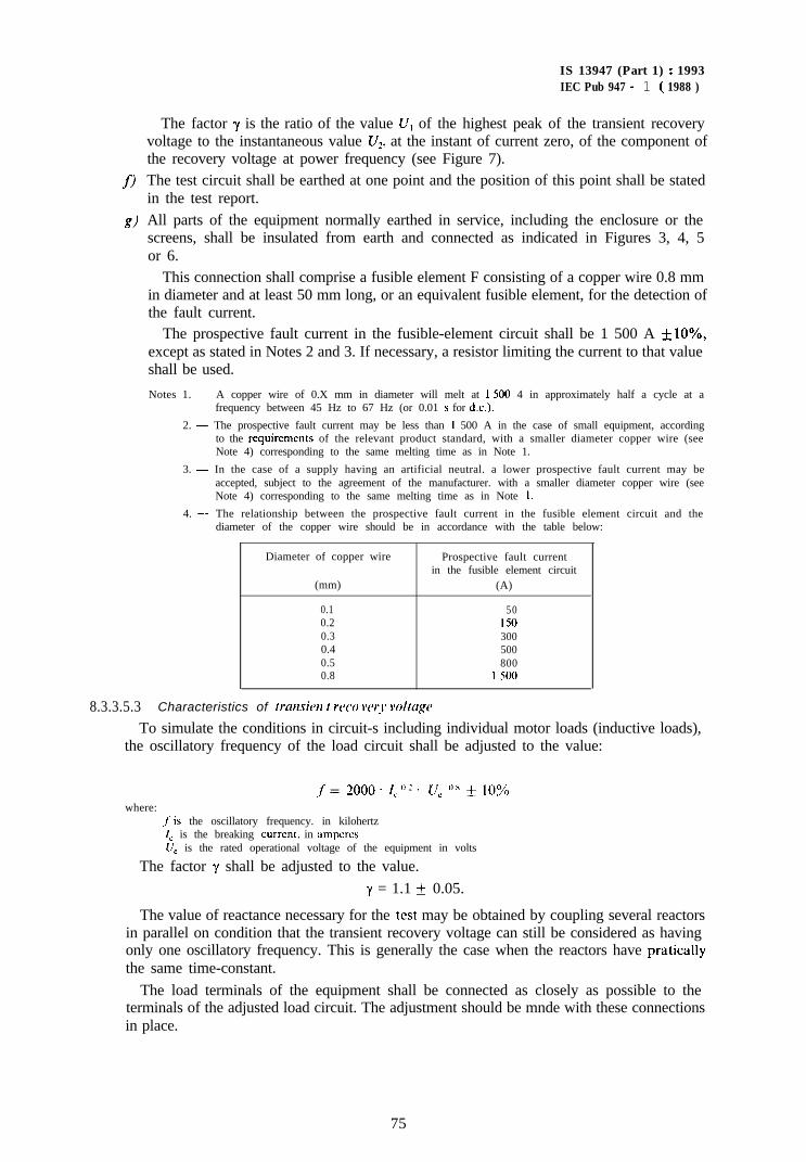
f)
The factor y is the ratio of the value U, of the highest peak of the transient recoveryvoltage to the instantaneous value U,, at the instant of current zero, of the component ofthe recovery voltage at power frequency (see Figure 7).The test circuit shall be earthed at one point and the position of this point shall be statedin the test report.
g) All parts of the equipment normally earthed in service, including the enclosure or thescreens, shall be insulated from earth and connected as indicated in Figures 3, 4, 5or 6.
This connection shall comprise a fusible element F consisting of a copper wire 0.8 mmin diameter and at least 50 mm long, or an equivalent fusible element, for the detection ofthe fault current.
The prospective fault current in the fusible-element circuit shall be 1 500 A + IO%,except as stated in Notes 2 and 3. If necessary, a resistor limiting the current to that valueshall be used.
Notes 1. - A copper wire of 0.X mm in diameter will melt at 1 500 4 in approximately half a cycle at afrequency between 45 Hz to 67 Hz (or 0.01 s for d.c.).
2. - The prospective fault current may be less than I 500 A in the case of small equipment, accordingto the requirements of the relevant product standard, with a smaller diameter copper wire (seeNote 4) corresponding to the same melting time as in Note 1.
3. - In the case of a supply having an artificial neutral. a lower prospective fault current may beaccepted, subject to the agreement of the manufacturer. with a smaller diameter copper wire (seeNote 4) corresponding to the same melting time as in Note I.
4. - The relationship between the prospective fault current in the fusible element circuit and thediameter of the copper wire should be in accordance with the table below:
Diameter of copper wire
(mm)
0.10.20.30.40.50.8
Prospective fault currentin the fusible element circuit
(A)
50150300500800
1 500
8.3.3.5.3 Characteristics of transit t rcco wr?* wltage
IS 13947 (Part 1) : 1993IEC Pub 947 - 1 ( 1988 )
To simulate the conditions in circuit-s including individual motor loads (inductive loads),the oscillatory frequency of the load circuit shall be adjusted to the value:
where:
f= 2000. 1<“2. u, ‘IX + 10%
f’is the oscillatory frequency. in kilohertzI, is the breaking current, in ampcrcsUC is the rated operational voltage of the equipment in volts
The factor y shall be adjusted to the value.y = 1.1 + 0.05.
The value of reactance necessary for the test may be obtained by coupling several reactorsin parallel on condition that the transient recovery voltage can still be considered as havingonly one oscillatory frequency. This is generally the case when the reactors have praticallythe same time-constant.
The load terminals of the equipment shall be connected as closely as possible to theterminals of the adjusted load circuit. The adjustment should be mnde with these connectionsin place.
75
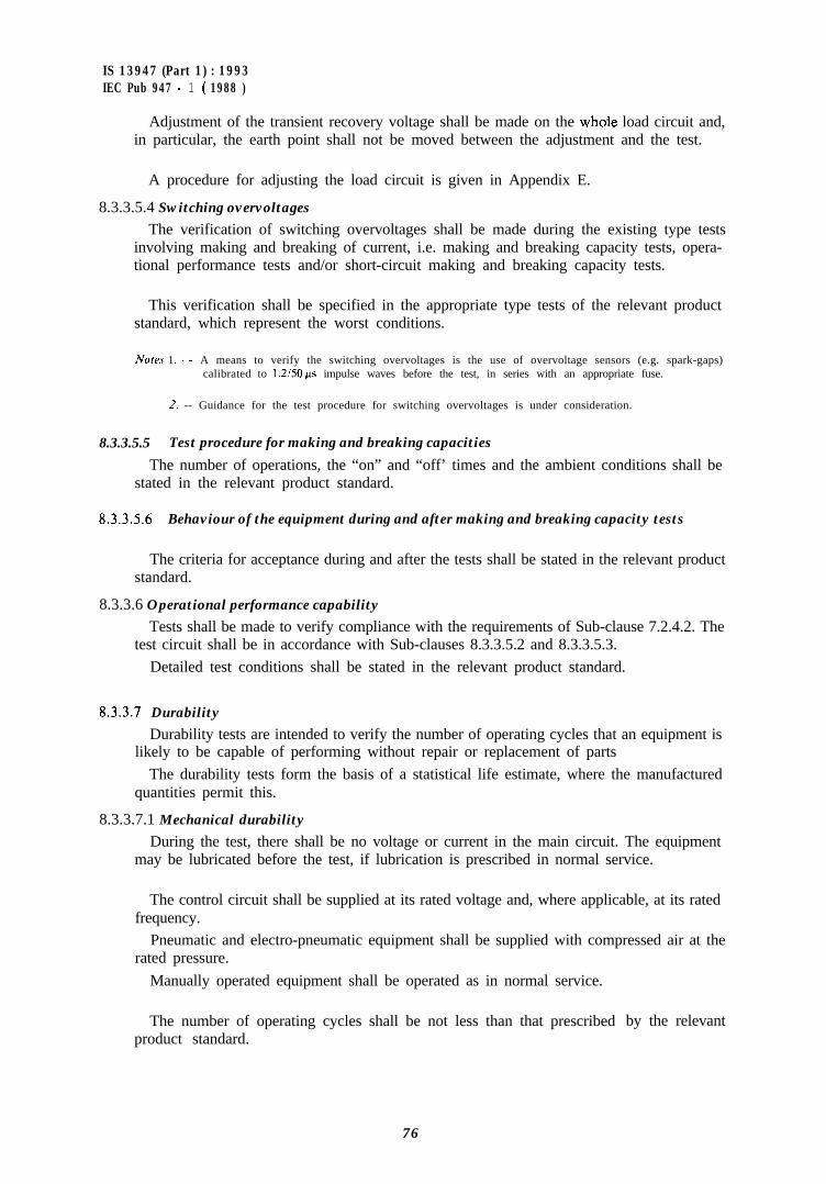
IS 13947 (Part 1) : 1993IEC Pub 947 - 1 ( 1988 )
Adjustment of the transient recovery voltage shall be made on the whole load circuit and,in particular, the earth point shall not be moved between the adjustment and the test.
A procedure for adjusting the load circuit is given in Appendix E.
8.3.3.5.4 Switching overvoltages
The verification of switching overvoltages shall be made during the existing type testsinvolving making and breaking of current, i.e. making and breaking capacity tests, opera-tional performance tests and/or short-circuit making and breaking capacity tests.
This verification shall be specified in the appropriate type tests of the relevant productstandard, which represent the worst conditions.
Nofes 1. - A means to verify the switching overvoltages is the use of overvoltage sensors (e.g. spark-gaps)calibrated to I .2i50 ps impulse waves before the test, in series with an appropriate fuse.
2. -- Guidance for the test procedure for switching overvoltages is under consideration.
8.3.3.5.5 Test procedure for making and breaking capacities
The number of operations, the “on” and “off’ times and the ambient conditions shall bestated in the relevant product standard.
8.3.3.5.6 Behaviour of the equipment during and after making and breaking capacity tests
The criteria for acceptance during and after the tests shall be stated in the relevant productstandard.
8.3.3.6 Operational performance capability
Tests shall be made to verify compliance with the requirements of Sub-clause 7.2.4.2. Thetest circuit shall be in accordance with Sub-clauses 8.3.3.5.2 and 8.3.3.5.3.
Detailed test conditions shall be stated in the relevant product standard.
8.3.3.7 Durability
Durability tests are intended to verify the number of operating cycles that an equipment islikely to be capable of performing without repair or replacement of parts
The durability tests form the basis of a statistical life estimate, where the manufacturedquantities permit this.
8.3.3.7.1 Mechanical durability
During the test, there shall be no voltage or current in the main circuit. The equipmentmay be lubricated before the test, if lubrication is prescribed in normal service.
The control circuit shall be supplied at its rated voltage and, where applicable, at its ratedfrequency.
Pneumatic and electro-pneumatic equipment shall be supplied with compressed air at therated pressure.
Manually operated equipment shall be operated as in normal service.
The number of operating cycles shall be not less than that prescribedproduct standard.
by the relevant
76
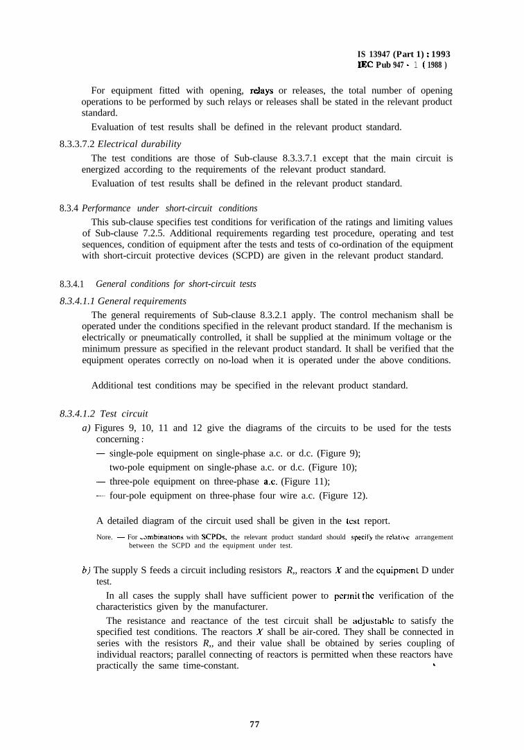
IS 13947 (Part 1) : 1993IEC Pub 947 - 1 ( 1988 )
For equipment fitted with opening, relays or releases, the total number of openingoperations to be performed by such relays or releases shall be stated in the relevant productstandard.
Evaluation of test results shall be defined in the relevant product standard.
8.3.3.7.2 Electrical durability
The test conditions are those of Sub-clause 8.3.3.7.1 except that the main circuit isenergized according to the requirements of the relevant product standard.
Evaluation of test results shall be defined in the relevant product standard.
8.3.4 Performance under short-circuit conditions
This sub-clause specifies test conditions for verification of the ratings and limiting valuesof Sub-clause 7.2.5. Additional requirements regarding test procedure, operating and testsequences, condition of equipment after the tests and tests of co-ordination of the equipmentwith short-circuit protective devices (SCPD) are given in the relevant product standard.
8.3.4.1 General conditions for short-circuit tests
8.3.4.1.1 General requirements
The general requirements of Sub-clause 8.3.2.1 apply. The control mechanism shall beoperated under the conditions specified in the relevant product standard. If the mechanism iselectrically or pneumatically controlled, it shall be supplied at the minimum voltage or theminimum pressure as specified in the relevant product standard. It shall be verified that theequipment operates correctly on no-load when it is operated under the above conditions.
Additional test conditions may be specified in the relevant product standard.
8.3.4.1.2 Test circuit
a) Figures 9, 10, 11 and 12 give the diagrams of the circuits to be used for the testsconcerning :
- single-pole equipment on single-phase a.c. or d.c. (Figure 9);- two-pole equipment on single-phase a.c. or d.c. (Figure 10);- three-pole equipment on three-phase a.c. (Figure 11);- four-pole equipment on three-phase four wire a.c. (Figure 12).
A detailed diagram of the circuit used shall be given in the test report.
Nore. - For -smbinations with SCPDs, the relevant product standard should specilji the relative arrangementbetween the SCPD and the equipment under test.
6) The supply S feeds a circuit including resistors R,, reactors X and the equipment D undertest.
In all cases the supply shall have sufficient power to permit the verification of thecharacteristics given by the manufacturer.
The resistance and reactance of the test circuit shall be adjustable to satisfy thespecified test conditions. The reactors X shall be air-cored. They shall be connected inseries with the resistors R,, and their value shall be obtained by series coupling ofindividual reactors; parallel connecting of reactors is permitted when these reactors havepractically the same time-constant. L
77
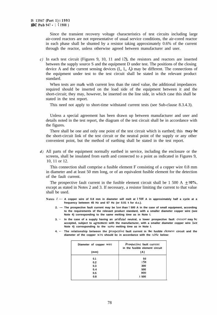
IS 13947 (Part 1) : 1993IEC Pub 947 - 1 ( 1988 )
C)
d)
Since the transient recovery voltage characteristics of test circuits including largeair-cored reactors are not representative of usual service conditions, the air-cored reactorin each phase shall be shunted by a resistor taking approximately 0.6% of the currentthrough the reactor, unless otherwise agreed between manufacturer and user.
In each test circuit (Figures 9, 10, 11 and 12) the resistors and reactors are insertedbetween the supply source S and the equipment D under test. The positions of the closingdevice A and the current sensing devices (I,, I,, 1,) may be different. The connections ofthe equipment under test to the test circuit shall be stated in the relevant productstandard.
When tests are ma& with current less than the rated value, the additional impedancesrequired should be inserted on the load side of the equipment between it and theshort-circuit; they may, however, be inserted on the line side, in which case this shall bestated in the test report.
This need not apply to short-time withstand current tests (see Sub-clause 8.3.4.3).
Unless a special agreement has been drawn up between manufacturer and user anddetails noted in the test report, the diagram of the test circuit shall be in accordance withthe figures.
There shall be one and only one point of the test circuit which is earthed; this mayb,bethe short-circuit link of the test circuit or the neutral point of the supply or any otherconvenient point, but the method of earthing shall be stated in the test report.
All parts of the equipment normally earthed in service, including the enclosure or thescreens, shall be insulated from earth and connected to a point as indicated in Figures 9,10, 11 or 12.
This connection shall comprise a fusible element F consisting of a copper wire 0.8 mmin diameter and at least 50 mm long, or of an equivalent fusible element for the detectionof the fault current.
The prospective fault current in the fusible element circuit shall be 1 500 A & IO%,except as stated in Notes 2 and 3. If necessary, a resistor limiting the current to that valueshall be used.
Notes I. -
2. -
3. -
4. -
A copper wire of 0.8 mm in diameter will melt at I 500 A in approximately half a cycle at afrequency between 45 Hz and 67 Hz (or 0.01 s for d.c.).
The prospective fault current may be less than I 500 A in the case of small equipment, accordingto the requirements of the relevant product standard, with a smaller diameter copper wire (seeNote 4) corresponding to the same melting time as in Note I.
In the case of a supply having an artikial neutral, a lower prospective fault currcnl may heaccepted, subject to agrecmcnt with the manufacturer, with a smaller diameter copper wire (seeNote 4) corresponding to the same melting time as in Note I.
The relationship between the prospective fault current in the fusible clement circuit and thediameter of the copper wire should bc in accordance with the table below:
Diameter of copper wire
(mm)
0.10.20.30.40.50.8
Prospective fault currentin the fusible element circuit
(A)
50150300500x00
I 500
78
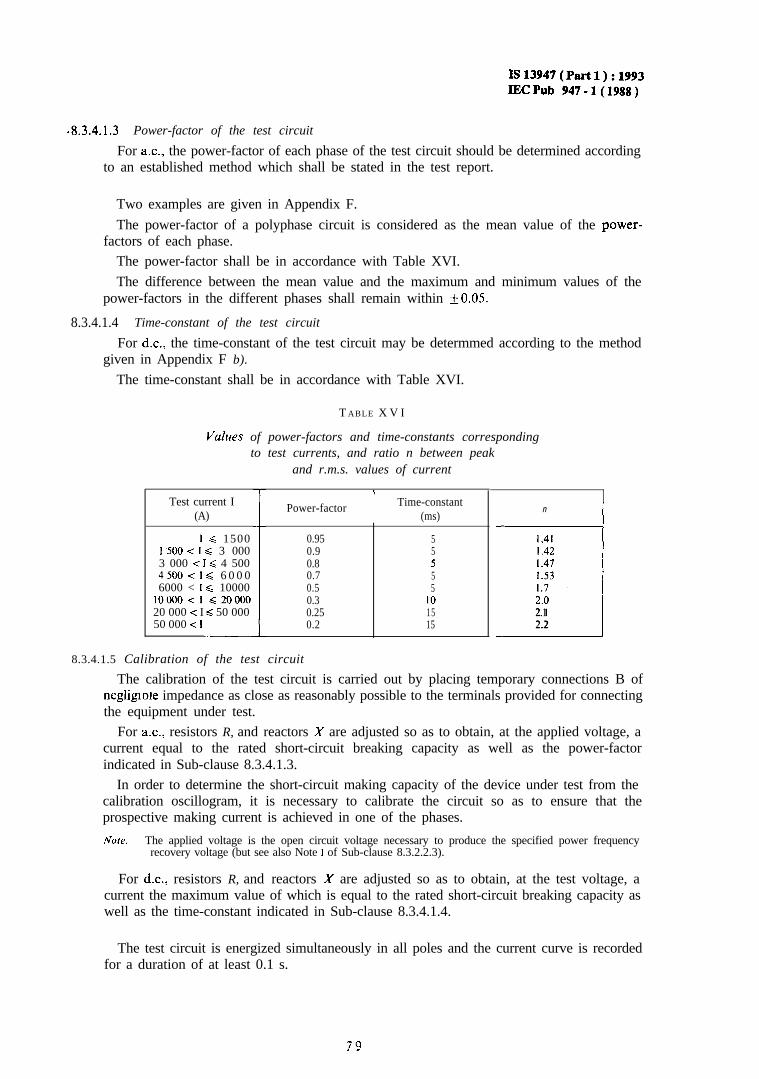
Isl3947(Part1):1993IECPub 947-l(1988)
-8.3.4.1.3 Power-factor of the test circuit
For ac., the power-factor of each phase of the test circuit should be determined accordingto an established method which shall be stated in the test report.
Two examples are given in Appendix F.
The power-factor of a polyphase circuit is considered as the mean value of the power-factors of each phase.
The power-factor shall be in accordance with Table XVI.The difference between the mean value and the maximum and minimum values of the
power-factors in the different phases shall remain within kO.05.
8.3.4.1.4 Time-constant of the test circuit
For d.c., the time-constant of the test circuit may be determmed according to the methodgiven in Appendix F b).
The time-constant shall be in accordance with Table XVI.
T ABLE X V I
V&es of power-factors and time-constants correspondingto test currents, and ratio n between peak
Test current I(A)
I< 15001500 < I c 3 0003 000 < I < 4 50045OO<l C 6 0 0 06000 < I < 10000
lOOOO<l d2000020 000 < I c 50 00050 000 < I
.-Iand r.m.s. values of current
IPower-factor Time-constant
(ms)n I
0.95 5 1.410.9 5 I .420.8 5 1.470.7 5 1.530.5 5 1.70.3 IO 2.00.25 15 II2.10.2 15 2.2
8.3.4.1.5 Calibration of the test circuit
The calibration of the test circuit is carried out by placing temporary connections B ofnegligiote impedance as close as reasonably possible to the terminals provided for connectingthe equipment under test.
For a.c., resistors R, and reactors X are adjusted so as to obtain, at the applied voltage, acurrent equal to the rated short-circuit breaking capacity as well as the power-factorindicated in Sub-clause 8.3.4.1.3.
In order to determine the short-circuit making capacity of the device under test from thecalibration oscillogram, it is necessary to calibrate the circuit so as to ensure that theprospective making current is achieved in one of the phases.
Note. - The applied voltage is the open circuit voltage necessary to produce the specified power frequencyrecovery voltage (but see also Note 1 of Sub-clause 8.3.2.2.3).
For d.c., resistors R, and reactors X are adjusted so as to obtain, at the test voltage, acurrent the maximum value of which is equal to the rated short-circuit breaking capacity aswell as the time-constant indicated in Sub-clause 8.3.4.1.4.
The test circuit is energized simultaneously in all poles and the current curve is recordedfor a duration of at least 0.1 s.
Is13947(Partl):1993lECPub947-l(1988)
For d.c. switching devices parting their contacts before the peak value of the calibrationcurve is reached, it is sufftcient to make a calibration record with additional pure resistancein the circuit to demonstrate that the rate of rise of the current expressed in amperes/secondis the same as for the test current and the time-constant specified (see Figure 15). Thisadditional resistance shall be such that the peak value of the calibration current curve is atleast equal to the peak value of the breaking current. This resistance shall be removed for theactual test (see Sub-clause 8.3.4.1.8 b)).
8.3.4.1.6 Test procedure
After calibration of the test circuit in accordance with Sub-clause 8.3.4.1.5, the temporaryconnections are replaced by the equipment under test, and its connecting cables, if any.
Tests for the performance under short-circuit conditions shall be made according to therequirements of the relevant product standard.
8.3.4.1.1 Behuviour of the equipment during short-circuit making and breaking tests
There shall be neither arcing nor flashover between poles, or between poles and frame, andno melting of the fusible element F in the leakage detection circuit (see Sub-clause8.3.4.1.2).
Tests concerning the evaluation of the emission of arc products are under considera-tion.
8.3.4.1.8 Interpretation of recordr
a) Determinution of the upplied voltuge and power-frequency recovery voltage
The applied voltage and the power-frequency recovery voltage are determined from therecord corresponding to the break test made with the apparatus under test, and evaluatedas indicated in Figure 13 for a.c. and in Figure 14 for d.c.
The voltage on the supply side shall be measured during the first complete cycle afterarc extinction in all poles and after high frequency phenomena have subsided (seeFigure 13).
If additional information is required regarding, for example, the voltage across indi-vidual poles, arcing time, arcing energy, switching overvoltage, etc., this may be obtainedby means of additional sensing devices across each pole, in which case the resistance ofeach of these measuring circuits shall be not less than 100 ohms per volts of the r.m.s.value of voltage across individual poles; this value shall be stated in the test report.
b) Determinution of the prospective breuking current
This determination is made by comparing the current curves, recorded during thecalibration of the circuit, with those recorded during the break test of the equipment (seeFigure 13).
For a.c., the ac. component of the prospective breaking current is taken as being equalto the r.m.s. value of the a.c. component of the calibration current at the instant whichcorresponds to the separation of the arcing contacts (value corresponding to A,/2 ,/z ofFigure 13, item (4)). The prospective breaking current shall be the average of the pros-
Is 13947 (Part 1) : 1993lECPub947-l(1988)
pective currents in all phases; the prospective current in any phase shall not vary from theaverage by more than 10% of the average.
For d.c., the value of the prospective breaking current is taken as being equal to themaximum value A, as determined from the calibration curve for equipment breakingbefore the current has reached its maximum value, and to the value A for equipmentbreaking after the current has passed its maximum value (see Figure 14, items a )and b)).
For d.c. equipment tested according to the requirements of Sub-clause 8.3.4.1.5, whenthe calibration of the test circuit has been made at a current 1, lower than the ratedbreaking capacity, the test is considered void if the actual breaking current I2 is higherthan I, and it shall be carried out again after a calibration at a current I3 of a higher valuethan Iz (see Figure 15).
The prospective breaking current A, = # shall be determined by calculating theresistance R of the test circuit from the resistors R, of the corresponding calibrationcircuits. The time-constant of the test circuit is given by:
T=&-.
c) Determination qf the prospective peak making current
The prospective peak making current is determined from the calibration record and itsvalue shall be taken as being that corresponding to A, of Figure 13, Item a) for a.c. andto A, of Figure 14 for d.c. In the case of a three-phase test it shall be taken as the highestof the three A, values obtained from the record.
No/e. - For tests on single-pole equipment, the prospective peak making current determined from thecalibration record may differ from the value of the actual making current corresponding to the test,depending on the instant of making.
8.3.4.1.9 Condition qf the equipment after the tests
After the tests, the equipment shall comply with the requirements of the relevant productstandard.
8.3.4:2 Short-circuit making and breaking capacities
The test procedure for verification of the rated short-circuit making and breaking capa-cities of the equipment shall be given in the relevant product standard.
8.3.4.3 Verifi:cation of the ability to carry the rated short-time withstand current
The test shall be made with the equipment in the closed position, at a prospective currentequal to the rated short-time withstand current and the corresponding operational voltageunder the general conditions of Sub-clause 8.3.4.1.
In the case of the test station having difficulty in making this test at the operationalvoltage, it may be made at any convenient lower voltage, but not less than 80 V, the actualtest current being, in this case, equal to the rated short-time withstand current I,,. This shallbe stated in the test report. If, however, momentary contact separation occurs during the test,the test shall be repeated at the rated operational voltage.
For this test, over-current releases, if any, likely to operate during the test, shall berendered inoperative.a) For a.c.
The tests shall be made at the rated frequency of the equipment with a tolerance off25%, and at the power-factor appropriate to the rated short-time withstand current in *accordance with Table XVI.
8:
IS 13947 (Part 1) : 1993lEC Pub 947 - 1 ( 1988 )
6)
c )
The value of current during the calibration is the average of the r.m.s. values of the a.c.components in all phases (see Sub-clause 4.3.6.1). When making the test at ratedoperational voltage, the calibration current is the prospective current; when making thetest at any lower voltage, the calibration current is the actual test current. In each phase,the current shall be within the tolerance specified in Sub-clause 8.3.2.2.2. The currentshall be applied for the specified time during which the r.m.s. value of its a.c. componentshall remain constant.
Note. - The value of the calibration test current may be increased beyond that permitted by the tolerance withthe consent of the manufacturer.
The highest peak value of the current during its first cycle shall be not less than n timesthe rated short-time withstand current, the value of n being that corresponding to thisvalue of current according to Table XVI.
When, however, the characteristics. of the testing station are such that the aboverequirements cannot be obtained, the following alternatives are permitted providedthat:
sf;‘” I:,,, dt > I2 x t,,where :t,,, is the duration of the test1 SI is the short timelteSt is the calibration current if the a.c component is not constant or > I,,,,I is the actual calibration current assumed to have a constant ax. component
If the decrement of the short-circuit current of the testing station is such that the ratedshort-time withstand current cannot be obtained for the rated time without applyinginitially an excessively high current, the r.m.s. value of the current may be permitted tofall during the test below the specified value, the duration being increased appropriately,provided that the value of the highest peak current is not less than that specified.
If, in order to obtain the required peak value, the r.m.s. value of the current has to beincreased above the specified current, the duration of the test shall be reduced accord-ingly.
For d.c.
The current shall be applied for the specified time and its mean value determined fromthe record shall be at least equal to the specified value.
When the characteristics of the testing station are such that the above requirementscannot be obtained for the rated time without applying initially an excessively highcurrent, the value of the current may be permitted to fall during the test below thespecified value, the duration being increased appropriately, provided that the maximumvalue of the current is not less than that specified.
If the testing station is unable to make these tests on d.c., they may, if agreed betweenmanufacturer and user, be made on a.~., provided suitable precautions are taken: forinstance, the peak value of current shall not exceed the permissible current.
Behuviour of the equipment during and after the test
Behaviour of the equipment during the test shall be defined in the relevant productstandard.
After the test, it shall be possible to operate the equipment by its normal operatingmeans.
(I
a2

IS 13947 (Part 1) : 1993IEC Pub 947 - 1 ( 1988 )
8.3.4.4 Co-ordination with short-circuit protective devices and rated conditional short-circuitcurrent
Test conditions and procedures, where applicable, shall be stated in the relevant productstandard.
83
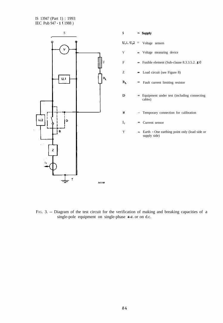
IS 13947 (Part 1) : 1993IEC Pub 947 - 1 ( 1988 )
SI
S =
U,l, u,2 =
V
F F
Z
RL
RL
J47/88
SUPPlY
Voltage sensors
Voltage measuring device
Fusible element (Sub-clause 8.3.3.5.2. gl)
Load circuit (see Figure 8)
Fault current limiting resistor
Equipment under test (including connectingcables)
Temporary connection for calibration
Current sensor
Earth - One earthing point only (load side orsupply side)
,
FIG. 3. -- Diagram of the test circuit for the verification of making and breaking capacities of asingle-pole equipment on single-phase a.c. or on d.c.
84
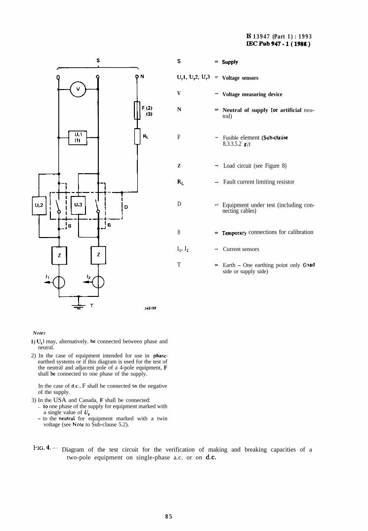
Q
,C--a-Url(1)
-3I -_
’-5u2 , I u,3
‘!fi_ _-
‘B_J
S =
U,l, u,2, u,3 =
V =
N =
F =
Z 2
RL =
D =
B
Ill 12
T
Is 13947 (Part 1) : 1993IECPub947-l(1988)
SUPPlY
Voltage sensors
Voltage measuring device
Neutral of supply (or artificial neu-tral)
Fusible element (Sub-clatisc8.3.3.5.2 g))
Load circuit (see Figure 8)
Fault current limiting resistor
Equipment under test (including con-necting cables)
Temporary connections for calibration
Current sensors
Earth - One earthing point only (:qadside or supply side)
I) U,I may, alternatively. bc connected between phase andneutral.
2) In the case of equipment intended for use in phase-earthed systems or if this diagram is used for the test ofthe neutral and adjacent pole of a 4-pole equipment, Fshall be connected to one phase of the supply.
In the case of d.c., F shall be connected lo the negativeof the supply.
3) In the USA and Canada, F shall be connected:_ lo one phase of the supply for equipment marked with
a single value of U,- to the neutral for equipment marked with a twin
voltage (see No@ to Sub-clause 5.2).
FIG. 4. -~ Diagram of the test circuit for the verification of making and breaking capacities of atwo-pole equipment on single-phase a.c. or on d.c.
85
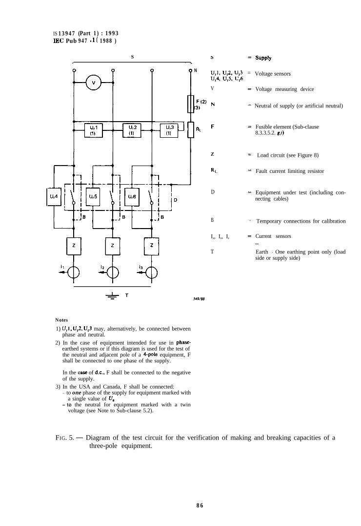
IS 13947 (Part 1) : 1993IEC Pub 947 - 1 ( 1988 )
S s =
-_LT
Notes
1) U,I. UJ, IJr3 may, alternatively, be connected betweenphase and neutral.
2) In the case of equipment intended for use in phase-earthed systems or if this diagram is used for the test ofthe neutral and adjacent pole of a 4-pole equipment, Fshall be connected to one phase of the supply.
In the caSe of d.c., F shall be connected to the negativeof the supply.
3) In the USA and Canada, F shall be connected:- to one phase of the supply for equipment marked with
a single value of V,- to the neutral for equipment marked with a twin
voltage (see Note to Sub-clause 5.2).
N Url, ur2, ur3 =Ur4, U,% U,6
V =
F(2) N(3)
=
J49/88
31 F =
Z =
RL =
D =
B =
I,, I,, I, zz
T
SUPPlY
Voltage sensors
Voltage measuring device
Neutral of supply (or artificial neutral)
Fusible element (Sub-clause8.3.3.5.2. gj)
Load circuit (see Figure 8)
Fault current limiting resistor
Equipment under test (including con-necting cables)
Temporary connections for calibration
Current sensors-
Earth - One earthing point only (loadside or supply side)
FIG. 5. - Diagram of the test circuit for the verification of making and breaking capacities of athree-pole equipment.
86
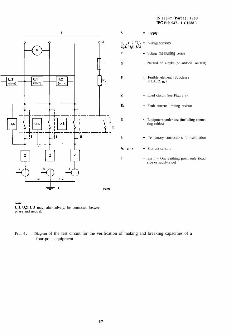
S s =
b---lV
Ur3(note)
Url(note)
P N U,l, u,2, u,3 =U,4, U,5> U,6
V
N
F
2
RL-1
.+-_-_ _
I LrI
-I_-_--41 D
I
.ID
IB_J
NoteU,l, U,2, U,3 may, alternatively, be connected betweenphase and neutral.
550/88
B
I,, 12, 13
T
=
IS 13947 (Part 1) : 1993IEC Pub 947 - 1 ( 1988 )
SUPPlY
Voltage sensors
Voltage measuring device
Neutral of supply (or artificial neutral)
Fusible element (Subclause8.3.3.5.2. g))
Load circuit (see Figure 8)
Fault current limiting resistor
Equipment under test (including connec-ting cables)
Temporary connections for calibration
Current sensors
Earth - One earthing point only (loadside or supply side)
FIG. 6. - Diagram of the test circuit for the verification of making and breaking capacities of afour-pole equipment.
87
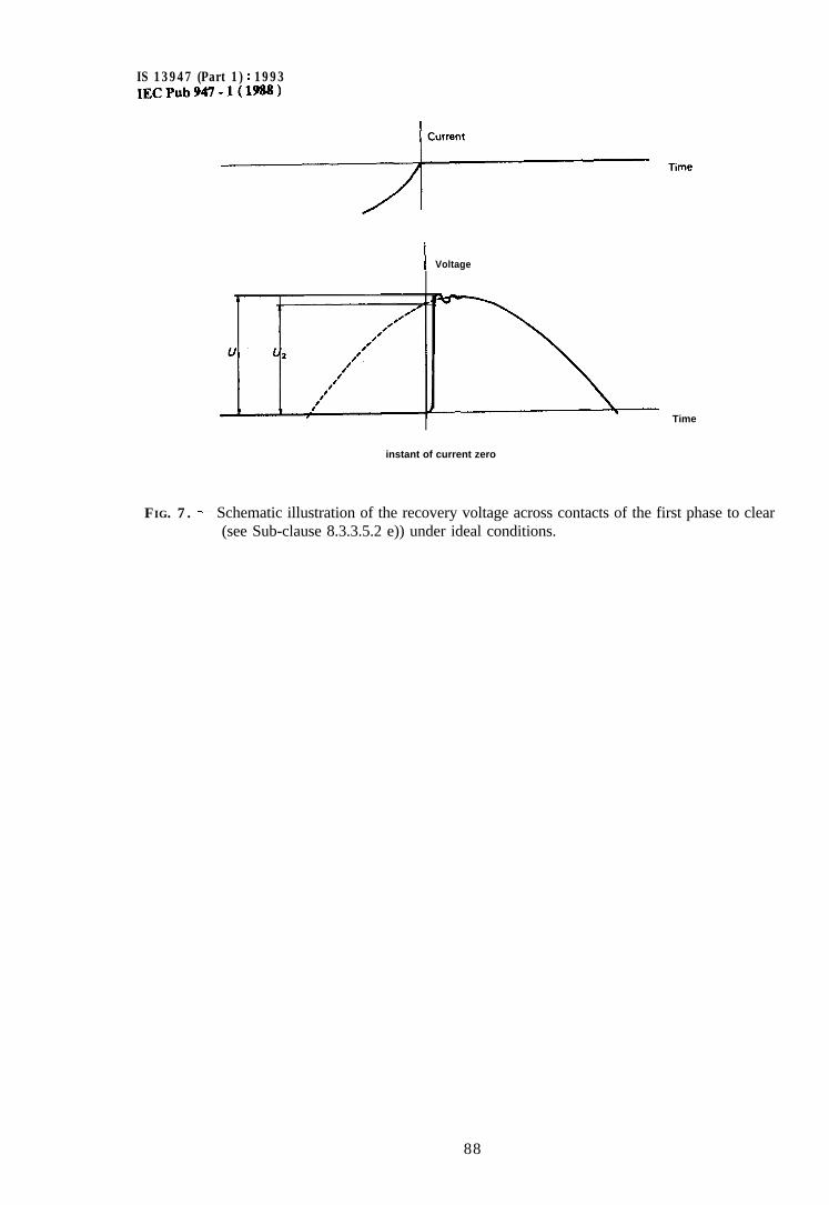
IS 13947 (Part 1) : 1993IECPub947-l(1988)
--TF-- TimeI Voltage
Time
instant of current zero
FIG. 7. - Schematic illustration of the recovery voltage across contacts of the first phase to clear(see Sub-clause 8.3.3.5.2 e)) under ideal conditions.
88
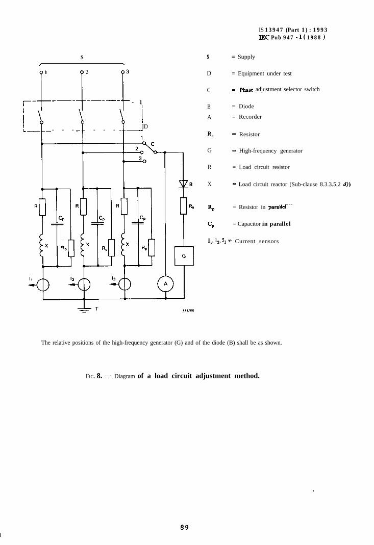
S/ \
1 2
--__I 13
_----1 - 1I
IIDI__ - - - - - - I
S
D
C
B
A
R,
G
R
X
Rp
CP
IS 13947 (Part 1) : 1993IEC Pub 947 - 1 ( 1988 )
= Supply
= Equipment under test
= phase adjustment selector switch
= Diode
= Recorder
= Resistor
= High-frequency generator
= Load circuit resistor
= Load circuit reactor (Sub-clause 8.3.3.5.2 d))
= Resistor in parallef“.
= Capacitor in parallel
11, 12, 1, = Current sensors
The relative positions of the high-frequency generator (G) and of the diode (B) shall be as shown.
FIG. 8. - Diagram of a load circuit adjustment method.
89
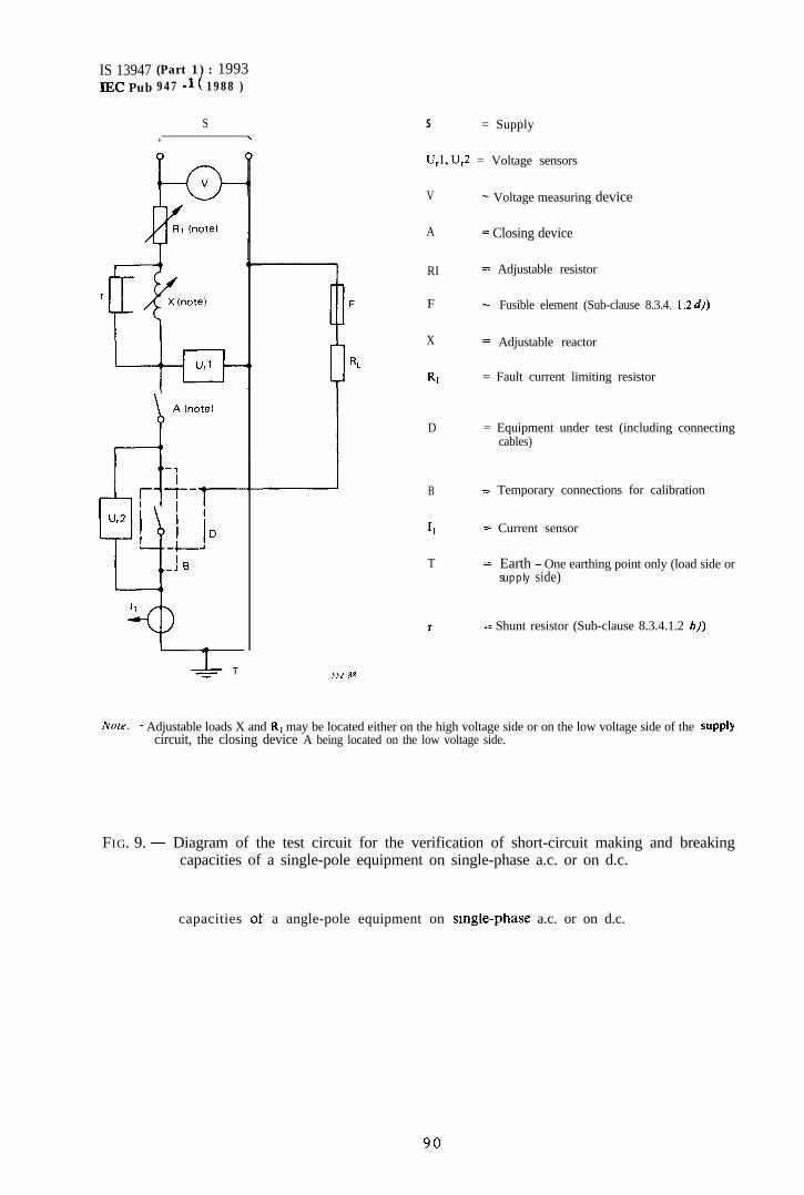
IS 13947 (Part 1) : 1993IEC Pub 947 - 1 ( 1988 )
S, \
‘52 88
S = Supply
U,l, U,2 = Voltage sensors
V
A
RI
F
X
Rl
D
B
II
T
r
= Voltage measuring device
= Closing device
= Adjustable resistor
= Fusible element (Sub-clause 8.3.4. I .2 d))
= Adjustable reactor
= Fault current limiting resistor
= Equipment under test (including connectingcables)
= Temporary connections for calibration
= Current sensor
= Earth - One earthing point only (load side orsupply side)
= Shunt resistor (Sub-clause 8.3.4.1.2 b))
Norr. - Adjustable loads X and RI may be located either on the high voltage side or on the low voltage side of the supplycircuit, the closing device A being located on the low voltage side.
FIG. 9. - Diagram of the test circuit for the verification of short-circuit making and breakingcapacities of a single-pole equipment on single-phase a.c. or on d.c.
capacities of a angle-pole equipment on smgle-phase a.c. or on d.c.
90
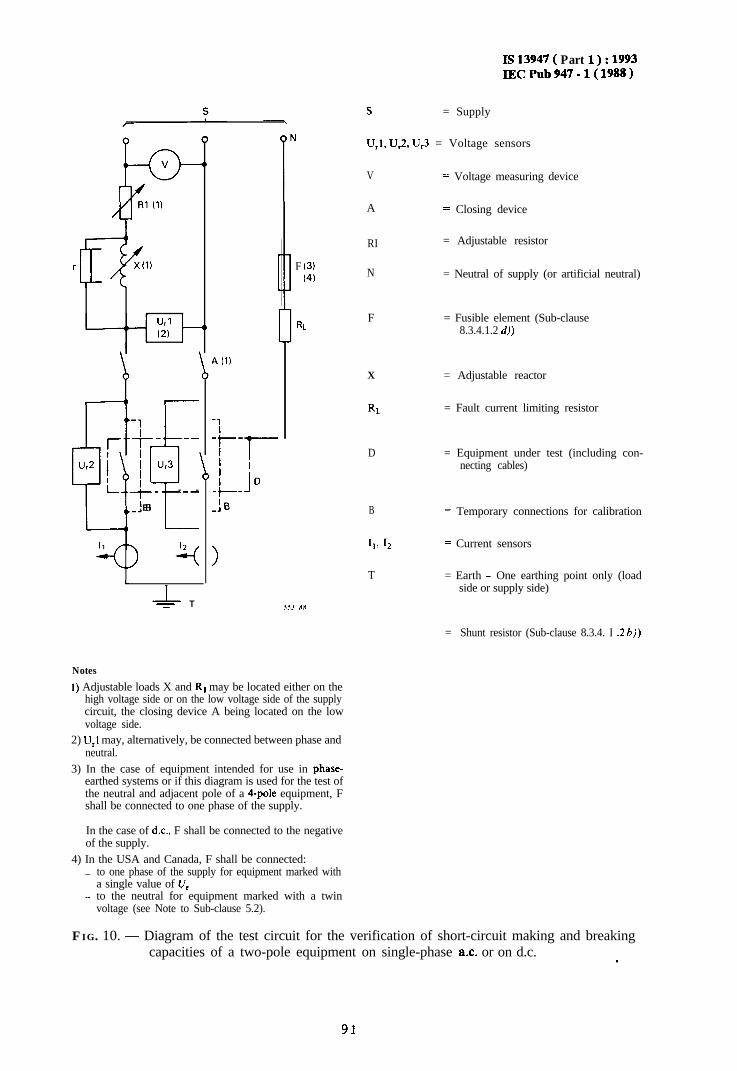
IS13947( Part 1):1993IECPub947-l(1988)
s = Supply
‘Jr1(2)
-1- T-j-- --
Aw I ur3
;]f
L_.+_ - -
‘El_J
11 12
4
L
T
A (11
-1
-+-l-I ID-t- 1_J
>
U,l, U,2, U,3 = Voltage sensors
F (3)(4)
V
A
RI
N
= Voltage measuring device
= Closing device
= Adjustable resistor
= Neutral of supply (or artificial neutral)
RLF = Fusible element (Sub-clause
8.3.4.1.2 d))
55.1 RR
X = Adjustable reactor
RL = Fault current limiting resistor
D
B
11, 12
T
= Equipment under test (including con-necting cables)
= Temporary connections for calibration
= Current sensors
= Earth - One earthing point only (loadside or supply side)
= Shunt resistor (Sub-clause 8.3.4. I .2 b))
Notes
I) Adjustable loads X and R, may be located either on thehigh voltage side or on the low voltage side of the supplycircuit, the closing device A being located on the lowvoltage side.
2) U,l may, alternatively, be connected between phase andneutral.
3) In the case of equipment intended for use in phase-earthed systems or if this diagram is used for the test ofthe neutral and adjacent pole of a 4-pole equipment, Fshall be connected to one phase of the supply.
In the case of d.c., F shall be connected to the negativeof the supply.
4) In the USA and Canada, F shall be connected:_ to one phase of the supply for equipment marked with
a single value of V,- to the neutral for equipment marked with a twin
voltage (see Note to Sub-clause 5.2).
FIG. 10. - Diagram of the test circuit for the verification of short-circuit making and breakingcapacities of a two-pole equipment on single-phase ax. or on d.c. .
91
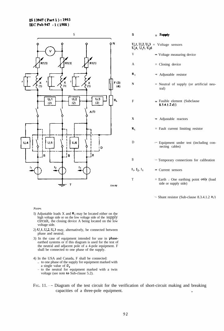
IS13947(Partl):1993IECPub947 -1(1988)
S\
r
SS4/88
I) Adjustable loads X and R, may be located either on thehigh voltage side or on the low voltage side of the supplycircuit, the closing device A being located on the lowvoltage side.
2) U,l, U,2, U,3 may, alternatively, be connected betweenphase and neutral.
3) In the case of equipment intended for use in phase-earthed systems or if this diagram is used for the test ofthe neutral and adjacent pole of a 4-pole equipment. Fshall be connected to one phase of the supply.
4) In the USA and Canada, F shall be connected:_ to one phase of the supply for equipment marked with
a single value of rl,._ to the neutral for equipment marked with a twin
voltage (see note lo Sub-clause 5.2).
S = supply
U,l, UJ, U,3 = Voltage sensorsU,4, U,5, U,6
V = Voltage measuring device
A = Closing device
Rl = Adjustable resistor
N = Neutral of supply (or artificial neu-tral)
F = Fusible element (Subclause8.3.4.1.2 d))
X = Adjustable reactors
RL = Fault current limiting resistor
D = Equipment under test (including con-necting cables)
B = Temporary connections for calibration
I,. I,, I, = Current sensors
T = Earth - One earthing point only (loadside or supply side)
= Shunt resistor (Sub-clause 8.3.4.1.2 hj)
FIG. 11. - Diagram of the test circuit for the verification of short-circuit making and breakingcapacities of a three-pole equipment. c
92 .
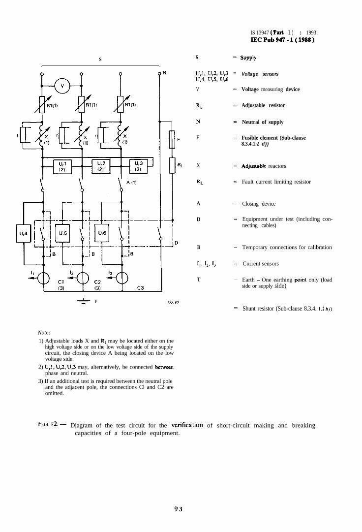
S
-IT-=- .sss/xx
Notes
1) Adjustable loads X and RI may be located either on thehigh voltage side or on the low voltage side of the supplycircuit, the closing device A being located on the lowvoltage side.
2) UJ, U,2, U,3 may, alternatively, be connected betweenphase and neutral.
3) If an additional test is required between the neutral poleand the adjacent pole, the connections Cl and C2 areomitted.
s =
UJ, UG, u,3 =U,4, U,S, U,6
V
RI
N
F
X
RL
A
D
B
67 I,. I,
T
IS 13947 (Pa* 1) : 1993lECPub947-l(1988)
SUPPlY
Voltage sensors
Voltage measuring device
Adjustable resistor
Neutral of supply
Fusible element (Sub-clause8.3.4.1.2 d))
Adjusiable reactors
Fault current limiting resistor
Closing device
Equipment under test (including con-necting cables)
Temporary connections for calibration
Current sensors
Earth - One earthing point only (loadside or supply side)
Shunt resistor (Sub-clause 8.3.4. I .2 bj)
,
FIG. 12. - Diagram of the test circuit for the yrification of short-circuit making and breakingcapacities of a four-pole equipment.
93
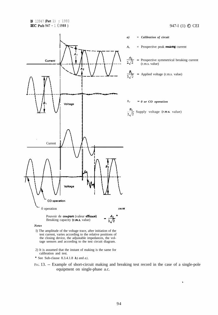
Is 13947 (Part 1) : 1993IEC Pub 947 - 1 ( 1988 )
Current
L0 operation
a) =
A, =
‘42
gE=
4
q=
947-l (1) 0 CEI
Calibration of circuit
Prospective peak makmg current
Prospective symmetrical breaking current(r.m.s. value)
Applied voltage (r.m.s. value)
bJ = 0 or CO operation
B2--- = Supply voltage (r.m.s. value)0
556/88
Pouvoir de coupure (valeur eficace)Breaking capacity (r.m.s. value)
Notes
I) The amplitude of the voltage trace, after initiation of thetest current, varies according to the relative positions ofthe closing device, the adjustable impedances, the vol-tage sensors and according to the test circuit diagram.
2) It is assumed that the instant of making is the same forcalibration and test.
* See Sub-clause 8.3.4.1.8 hl and c).
FIG. 13. -- Example of short-circuit making and breaking test record in the case of a single-poleequipment on single-phase a.c.
94
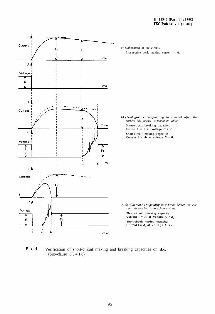
IS 13947 (Part 1) : 1993IECPub 947 - 1 ( 1988 )
Current 1; ,;,;qt____
T;;“ol/$ 1 3
a) Calibration of the circuit.
Prospective peak making current = A ,
b) Oscillogrum corresponding to a break after thecurrent has passed its maximum value.
Short-circuit breaking capacity:Current I = A at voltage U = B,
Short-circuit making capacity:Current I = AZ at voltage CT = B
c) Oscillogrtrm correspomiing to a break before the cur-rent has reached its ma.\-imum value.
Short-circuit breaking capacity:Current I = A, at voltage U = B2
Short-circuit making capacity:Current I = A, at vol tage U = B
I%. 14. - Verification of short-circuit making and breaking capacities on d.c.(Sub-clause 8.3.4.1.8).
95
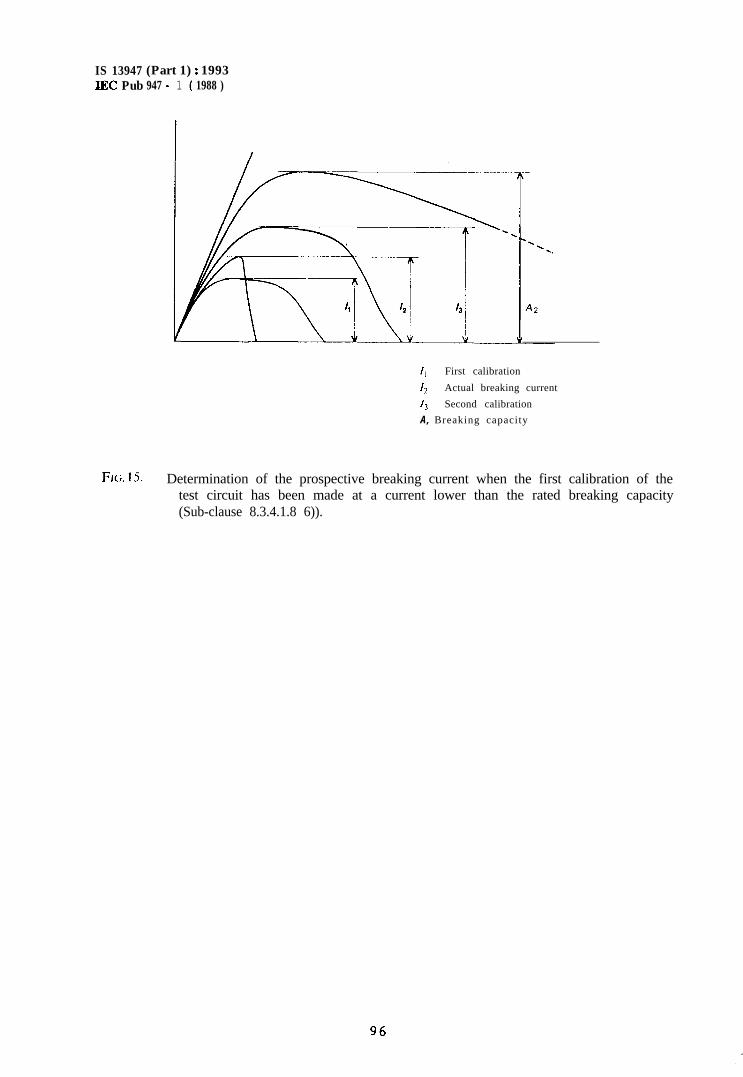
IS 13947 (Part 1) : 1993IEC Pub 947 - 1 ( 1988 )
II First calibration
4 Actual breaking current
13 Second calibration
A, Breaking capacity
FJG. 15. - Determination of the prospective breaking current when the first calibration of thetest circuit has been made at a current lower than the rated breaking capacity(Sub-clause 8.3.4.1.8 6)).
96
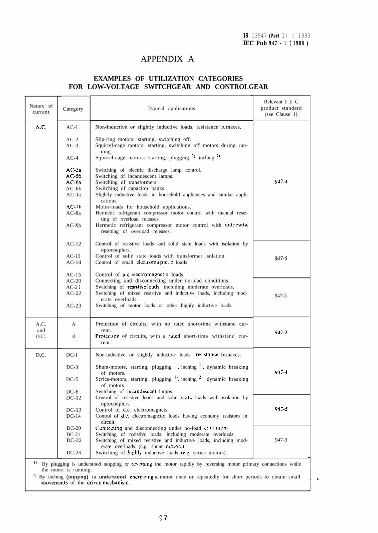
IS 13947 (Part 1) : 1993IEC Pub 947 - 1 ( 1988 )
Nature ofcurrent
AC
A.C.andD.C.
D.C.
APPENDIX A
EXAMPLES OF UTILIZATION CATEGORIESFOR LOW-VOLTAGE SWITCHGEAR AND CONTROLGEAR
Category
AC-l
AC-2AC-3
AC-4
AC-5aAC-5bAC&aAC-6bAC-la
AC-7bAC-8a
AC-Xb
AC-12
AC-13AC-14
AC-15AC-20AC-2 IAC-22
AC-23
A
B
DC-I
DC-3
DC-5
DC-6DC-12
DC-13DC-14
DC-20DC-21DC-22
DC-23
Typical applications
Non-inductive or slightly inductive loads, resistance furnaces.
Slip-ring motors: starting, switching off.Squirrel-cage motors: starting, switching off motors during run-
ning.Squirrel-cage motors: starting, plugging ‘1, inching *).
Switching of electric discharge lamp control.Switching of incandescent lamps.Switching of transformers.Switching of capacitor banks.Slightly inductive loads in household appliances and similar appli-
cations.Motor-loads for household applications.Hermetic refrigerant compressor motor control with manual reset-
ting of overload releases.Hermetic refrigerant compressor motor control with automalic
resetting of overload releases.
Control of resistive loads and solid state loads with isolation byoptocouplers.
Control of solid state loads with transformer isolation.Control of small electromagnetic loads.
Control of ac. electromagnetic loads.Connecting and disconnecting under no-load conditions.Switching of rctitivc loads. including moderate overloads.Switching of mixed resistive and inductive loads, including mod-
erate overloads.Switching of motor loads or other highly inductive loads.
Protection of circuits, with no rated short-time withstand cur-rent.
Protection of circuits, with a rated short-time withstand cur-rent.
Non-inductive or slightly inductive loads, resistance furnaces.
Shunt-motors, starting, plugging ‘I, inching 2), dynamic breakingof motors.
Scrics-motors, starting, plugging I), inching *), dynamic breakingof motors.
Switching of incandcsccnt lamps.Control of rcsistivc loads and solid state loads with isolation by
optocouplers.Control of d.c. clcctromagncts.Control of dc. clcctromagnctic loads having economy resistors in
circuit.Connecting and disconnecting under no-load condittons.Switching of rcsistivc loads. including moderate overloads.Switching of mixed resistive and inductive loads, including mod-
erate overloads (c.g. shunt molars).Switching of htghly inductive loads (eg. series motors).
Relevant I E Cproduct standard
(see Clause 1)
947-4
947-5
947-3
941-2
947-4
947-5
947-3
‘) By plugging is understood stopping or rcvcrsing the motor rapidly by reversing motor primary connections whilethe motor is running.
2, By inching (jogging) is understood energizing a motor once or repeatedly for short periods to obtain smallmovcmcnts of the driven mechanism.
97
IS 13947 (Part 1) : 1993IEC Pub 947 - 1 ( 1988 )
APPENDIX B
SUITABILITY OF THE EQUIPMENT WHEN CONDITIONSFOR OPERATION IN SERVICE DIFFER FROM THE NORMAL CONDITIONS
If the conditions for operation in service and the application differ from those given in thisstandard, the user shall state the deviations from the standard conditions and consult themanufacturer on the suitability of the equipment for use under such conditions.
B I, Examples of conditions differing from normal
B 1.1 Ambient air temperature
The expected range of ambient air temperature can be lower than -5 “C or higher than+40 “C.
B1.2 Altitude
The altitude of the place of installation is more than 2 000 m.
B I .3 Atmospheric conditions
The atmosphere in which the equipment is to be installed may have a relative humiditygreater than the values specified in Sub-clause 6.1.3 or contain an abnormal amount of dust,acids, corrosive gases, etc.
The equipment is to be installed near the sea.
B 1.4 Conditions of installation
B2.
B3.
B4.
The equipment may be fitted to a moving device, or its support may assume a slopingposition either permanently or temporarily (equipment fitted aboard ships), or it may beexposed in service to abnormal shocks or vibrations.
Connections with other apparatus
The user shall inform the manufacturer of the type and dimensions of electrical connec-tions with other apparatus in order to enable him to provide enclosures and terminalsmeeting the conditions of installation and temperature-rise prescribed by this standardand/or the relevant product standard and also to enable him to provide space, wherenecessary, to spread out conductors within the enclosure.
Auxiliary contacts
The user shall specify the number and type of auxiliary contacts to be supplied to satisfyrequirements such as signalling, interlocking, and similar functions.
Special applications
The user shall indicate to the manufacturer if the equipment could be used for specialapplications not covered by this standard and/or the relevant product standard.
98
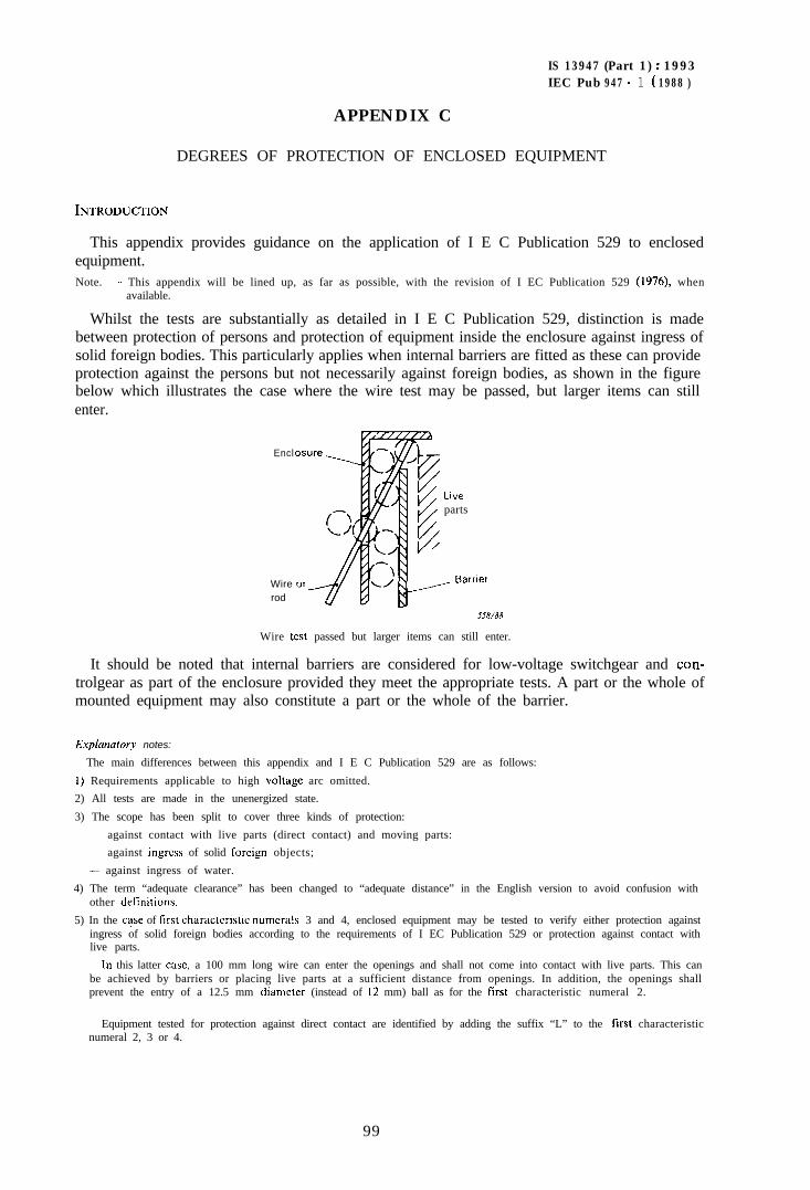
IS 13947 (Part 1) : 1993IEC Pub 947 - 1 ( 1988 )
APPENDIX C
DEGREES OF PROTECTION OF ENCLOSED EQUIPMENT
INTRODUCTION
This appendix provides guidance on the application of I E C Publication 529 to enclosedequipment.Note. - This appendix will be lined up, as far as possible, with the revision of I EC Publication 529 (1976), when
available.
Whilst the tests are substantially as detailed in I E C Publication 529, distinction is madebetween protection of persons and protection of equipment inside the enclosure against ingress ofsolid foreign bodies. This particularly applies when internal barriers are fitted as these can provideprotection against the persons but not necessarily against foreign bodies, as shown in the figurebelow which illustrates the case where the wire test may be passed, but larger items can stillenter.
Encl
Wirerod
Liveparts
_ Barr .ier
Wire test passed but larger items can still enter.
It should be noted that internal barriers are considered for low-voltage switchgear and con-trolgear as part of the enclosure provided they meet the appropriate tests. A part or the whole ofmounted equipment may also constitute a part or the whole of the barrier.
Explunatory notes:
The main differences between this appendix and I E C Publication 529 are as follows:
I) Requirements applicable to high voltage arc omitted.
2) All tests are made in the unenergized state.
3) The scope has been split to cover three kinds of protection:
- against contact with live parts (direct contact) and moving parts:
- against ingress of solid foreign objects;
- against ingress of water.
4) The term “adequate clearance” has been changed to “adequate distance” in the English version to avoid confusion withother delinitions.
5) In the c+se of lirst characteristic numerals 3 and 4, enclosed equipment may be tested to verify either protection againstingress of solid foreign bodies according to the requirements of I EC Publication 529 or protection against contact withlive parts.
In this latter cast, a 100 mm long wire can enter the openings and shall not come into contact with live parts. This canbe achieved by barriers or placing live parts at a sufficient distance from openings. In addition, the openings shallprevent the entry of a 12.5 mm diamctcr (instead of I2 mm) ball as for the first characteristic numeral 2.
Equipment tested for protection against direct contact are identified by adding the suffix “L” to the Iirst characteristicnumeral 2, 3 or 4.
99
IS 13947 (Port 1) : 1993EC Pub 947 - 1 ( 1988 )
Table Cl has been amended accordingly, thus highlighting the difference between protection against ingress of foreignobjects and protection against direct contact.
6) For dust protected equipment according to first numerals 5 and 6 for category 1 enclosures reference to drain holes hasbeen omitted. The tests laid down in I E C Publication 529 are technically impossible and have been modified.
The method of connectjng equipment to circuits in vacuum has been specified in a manner which is in line withcurrent practice.
7) For the second characteristic numeral 8, no ingress of water is permitted in order to differentiate more clearly betweenhermetically sealed equipment and that which is protected against the effects of the immersion only.
8) A dielectric test has been instituted for the second characteristic numeral as this is the only positive test available and notsubject to interpretation regarding the verification of the integrity of installation, etc. This particularly applies as thetests are implemented in the unenergized state.
9) Differences with I E C Publication 529 are marked by a vertical line jn the left-hand margin.
C 1. General
This appendix provides information for specifying the degree of protection for enclosedequipment hereinafter referred to as equipment.
It also specifies type tests to check the degree of protection on the various types ofenclosures of enclosed equipment.
All enclosed equipment is intended to provide protection as follows:cr) Protection of persons against contact with live parts and against contact with moving
parts (other than smooth rotating shafts and the like) inside the enclosure,
andhJ Protection of the equipment inside the enclosure against the ingress of solid foreign
objects.and/orc) Protection of the equipment inside the enclosure against harmful ingress of water.
The appendix does not specify the protection of equipment against mechanical damage,risk of explosion or conditions such as moisture (produced by example, by condensation)corrosive vapours, fungus, or vermin.
Internal barriers are considered for low-voltage switchgear and controlgear as part of theenclosure provided they meet at least the requirement of degree IP2X.
A part or the whole of mounted equipment may constitute a part or the whole of abarrier.
The basic tests and conditions are given in IEC Publication 529 but specific tests andinterpretations apply to openings such as drain holes and ventilating openings etc. Allopenings of enclosed equipment shall comply with the IP code assigned to this equip-ment.
Drain holes are openings situated at the bottom of the enclosure and are intended toprevent the accumulation of water due to condensation and/or ingress of water into theenclosure. They shall comply with the basic requirements for openings and not be smallerthan 2.5 mm in diameter.
C2. Designation (classification system)
The designation to indicate the degree of protection consists of the characteristic letters 1Pfollowed by two numerals (the “characteristic numerals”) indicating conformity with the
100
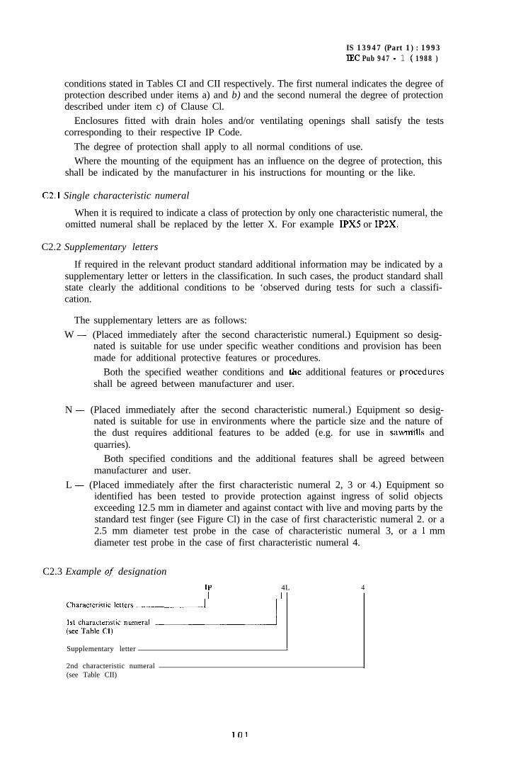
IS 13947 (Part 1) : 1993IEC Pub 947 - 1 ( 1988 )
conditions stated in Tables CI and CII respectively. The first numeral indicates the degree ofprotection described under items a) and b) and the second numeral the degree of protectiondescribed under item c) of Clause Cl.
Enclosures fitted with drain holes and/or ventilating openings shall satisfy the testscorresponding to their respective IP Code.
The degree of protection shall apply to all normal conditions of use.Where the mounting of the equipment has an influence on the degree of protection, this
shall be indicated by the manufacturer in his instructions for mounting or the like.
C2.1 Single characteristic numeral
When it is required to indicate a class of protection by only one characteristic numeral, theomitted numeral shall be replaced by the letter X. For example IPXS or IP2X.
C2.2 Supplementary letters
If required in the relevant product standard additional information may be indicated by asupplementary letter or letters in the classification. In such cases, the product standard shallstate clearly the additional conditions to be ‘observed during tests for such a classifi-cation.
The supplementary letters are as follows:W -’ (Placed immediately after the second characteristic numeral.) Equipment so desig-
nated is suitable for use under specific weather conditions and provision has beenmade for additional protective features or procedures.
Both the specified weather conditions and the additional features or proceduresshall be agreed between manufacturer and user.
N - (Placed immediately after the second characteristic numeral.) Equipment so desig-nated is suitable for use in environments where the particle size and the nature ofthe dust requires additional features to be added (e.g. for use in sawMills andquarries).
Both specified conditions and the additional features shall be agreed betweenmanufacturer and user.
L - (Placed immediately after the first characteristic numeral 2, 3 or 4.) Equipment soidentified has been tested to provide protection against ingress of solid objectsexceeding 12.5 mm in diameter and against contact with live and moving parts by thestandard test finger (see Figure Cl) in the case of first characteristic numeral 2. or a2.5 mm diameter test probe in the case of characteristic numeral 3, or a 1 mmdiameter test probe in the case of first characteristic numeral 4.
C2.3 Example qf designation
IP 4L 4
;;~;;;;;~::m: 1Supplementary letter
2nd characteristic numeral(see Table CII)
i Ii
lfll
IS 13947 (Part 1) : 1993IEC Pub 947 - 1 ( 1988 )
Equipment so designated provides protection against contacts with live and moving partsaccording to Sub-clause C2.2, supplementary letter L, against ingress of solid objects greaterthan 12.5 mm and against splashing water.
C3. Degrees of protection - first characteristic numera1
The first characteristic numeral indicates the degree of protection provided by the equip-ment both to the persons and to the equipment inside the enclosure.
Table CT gives, in column 3, brief details of objects which will be “excluded” from theenclosure for each of the degrees of protection represented by the first characteristicnumeral.
The term “excluded” implies that a part of the body or a tool or a wire held by a person,either will not enter the enclosure or, if it is permitted to enter, that adequate distance will bemaintained between it and the live parts or dangerous moving parts (smooth rotating shaftsand the like are not considered dangerous).
Note. ~~ The delinition for “adequate distance” is given in Sub-clause C6.1
Column 3 of Table CI also indicates the minimum size of solid foreign bodies which will beexcluded.
Nore. ~~ Equipment assigned a first characteristic numeral of I to 4 will exclude both regularly and irregularlyshaped solid objects provided that three mutually perpendicular dimensions of the object exceed theappropriate value in column 3.
Compliance of enclosed equipment with a stated degree of protection implies that theenclosure will also comply with all lower degrees of protection in Table CI. In consequence,the tests establishing these degrees of protection need not be carried out.
102
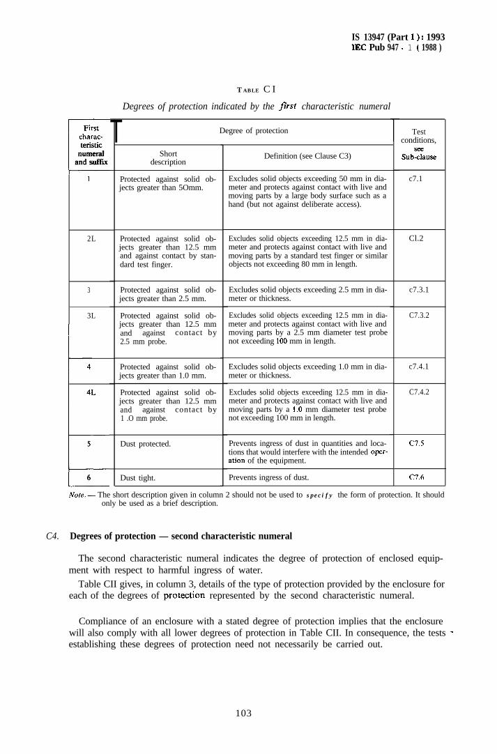
IS 13947 (Part 1) : 1993IEC Pub 947 - 1 ( 1988 )
Firstcharac-Jteristicnumeral
and suffix
1
2L
3
3L
I4L
b5
T
T ABLE C I
Degrees of protection indicated by the first characteristic numeral
Shortdescription
Degree of protection
Protected against solid ob-jects greater than 5Omm.
Protected against solid ob- Excludes solid objects exceeding 12.5 mm in dia-jects greater than 12.5 mm meter and protects against contact with live andand against contact by stan- moving parts by a standard test finger or similardard test finger. objects not exceeding 80 mm in length.
Protected against solid ob- Excludes solid objects exceeding 2.5 mm in dia-jects greater than 2.5 mm. meter or thickness.
Protected against solid ob- Excludes solid objects exceeding 12.5 mm in dia-jects greater than 12.5 mm meter and protects against contact with live andand against contact by moving parts by a 2.5 mm diameter test probe2.5 mm probe. not exceeding 100 mm in length.
Protected against solid ob- Excludes solid objects exceeding 1.0 mm in dia-jects greater than 1.0 mm. meter or thickness.
Protected against solid ob- Excludes solid objects exceeding 12.5 mm in dia-jects greater than 12.5 mm meter and protects against contact with live andand against contact by moving parts by a I .O mm diameter test probe1 .O mm probe. not exceeding 100 mm in length.
Dust protected. Cl.5
CT.6/
6 Dust tight. Prevents ingress of dust.
Note. - The short description given in column 2 should not be used to specify the form of protection. It shouldonly be used as a brief description.
Definition (see Clause C3)
Excludes solid objects exceeding 50 mm in dia-meter and protects against contact with live andmoving parts by a large body surface such as ahand (but not against deliberate access).
Prevents ingress of dust in quantities and loca-tions that would interfere with the intended opcr-ation of the equipment.
Testconditions,
Subzuse
c7.1
Cl.2
c7.3.1
C7.3.2
c7.4.1
C7.4.2
C4. Degrees of protection - second characteristic numeral
The second characteristic numeral indicates the degree of protection of enclosed equip-ment with respect to harmful ingress of water.
Table CII gives, in column 3, details of the type of protection provided by the enclosure foreach of the degrees of protectipn represented by the second characteristic numeral.
Compliance of an enclosure with a stated degree of protection implies that the enclosurewill also comply with all lower degrees of protection in Table CII. In consequence, the tests _establishing these degrees of protection need not necessarily be carried out.
103
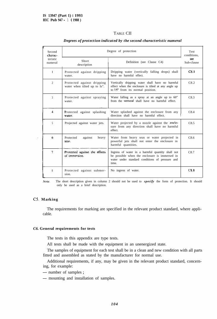
IS 13947 (Part 1) : 1993IEC Pub 947 - 1 ( 1988 )
TABLE CII
Degrees of protection indicated by the second characteristic numeral
rSecondcharac-
Degree of protection Testconditions,
teristicnumeral Short
description IDefinition (see Clause C4)
seeSub-clause
1 Protected against dripping Dripping water (vertically falling drops) shall C8.lwater. have no harmful effect.
L
2 Protected against drippingwater when tilted up to Is”.
Vertically dripping water shall have no harmfuleffect when the enclosure is tilted at any angle upto 15” from its normal position.
C8.2
3 Protected against sprayingwater.
Water falling as a spray at an angle up to 60”from the vertrcal shall have no harmful effect.
C8.3
Protected against splashing Water splashed against the enclosure from any C8.4direction shall have no harmful effect.
5 Projected against water jets. Water projected by a nozzle against the enclo-sure from any direction shall have no harmfuleffect.
C8.5
6 1 Protected against heavy
8 Protected against submer-sion.
Water from heavy seas or water projected inpowerful jets shall not enter the enclosure inharmful quantities.
C8.6
Ingress of water in a harmful quantity shall notbe possible when the enclosure is immersed inwater under standard conditions of pressure andtime.
C8.7
No ingress of water. C8.8
/Vole. - The short description given in column 2 should not be used to specify the form of protection. It shouldonly be used as a brief description.
C5. Marking
The requirements for marking are specified in the relevant product standard, where appli-cable.
C6. General requirements for tests
The tests in this appendix are type tests.All tests shall be made with the equipment in an unenergized state.The samples of equipment for each test shall be in a clean and new condition with all parts
fitted and assembled as stated by the manufacturer for normal use.Additional requirements, if any, may be given in the relevant product standard, concern-
ing, for example:- number of samples ;
- mounting and installation of samples.
104
IS 13947 (Part 1) : 1993IEC Pub 947 - 1 ( 1988 )
In the absence of such requirements, the manufacturer’s instructions shall apply.
The interpretation of test results is given in Clauses C7 and C8.
C6.1 Adequate distance
For the purpose of the following test clauses in this appendix, the term “adequatedistance” has the following meaning: the test device (sphere, finger, wire, etc.) does not touchlive parts or moving parts ot.her than non-dangerous parts such as smooth rotatingshafts.
C7. Test for first characteristic numeral
C7.1 Test for first numerul I
The test is made with a rigid sphere of 50 +!“’ mm in diameter applied against theopening(s) of the equipment with a force of 50 N _t 10%.
The protection is satisfactory if the sphere does not pass through any opening andadequate distance is maintained to parts which are normally live in service or movkg partsinside the enclosure.
C7.2 Test ,for ,first numcrul 2
The test comprises two parts a) and h), which shall be effected as follows:
a) Finger test
The test is made with a metal test linger as shown in Figure Cl. Both joints of this fingermay be bent through an angle of 90” with respect to the axis of the finger, but in one andthe same direction only. The linger is pushed without undue force (not more than 10 N)against any openings in the enclosure, and if it enters, it is placed in the most unfavour-able position within the equipment.
The protection is satisfactory if adequate distance is maintained between the test fingerand live or moving parts inside the enclosure.
For this mechanical test, the internal moving parts may be operated slowly, where this ispossible.
A low-voltage supply (of not less than 40 V) in series with a suitable lamp may beconnected between the test linger and the live parts inside the enclosure. Conducting partscovered only with varnish or paint, or protected by oxidation or by a similar process, shall becovered with a metal foil electrically connected to those parts which are normally live inservice.
The protection is satisfactory if the lamp does not light.
6) Sphere test
The test is made with a rigid sphere of 12.5 +!’ mm in diameter applied to the openingsof the enclosure with a force of 30 N f 10%.
The protection is satisfactory if the sphere does not pass through any opening andadequate distance is maintained to live or moving parts inside the enclosure.
C7.3 Test jar ,first numeral 3
105
IS 13947 (Part 1) : 1993IEC Pub 947 - 1 ( 1988 )
C7.3.1 Protection against ingress of solid foreign objects
The test is made with a straight rigid steel wire or rod of 2.5 +8.05 mm diameter appliedwith a force of 3 N + 10%. The end of the wire or rod shall be free from burrs and at rightangles to its length.
The protection is satisfactory if the wire or rod cannot enter the enclosure.
C7.3.2 Protection against contacts with live and moving parts
The test is made with a straight rigid steel wire or rod of 2.5’:“’ mm diameter and100 mm long with a force of 3 N + 10%. The end ofthe wire or rod shall be hemisphericallyshaped.
The protection is satisfactory if adequate distance is maintained with live and moving partsinside the enclosure.
In addition, the sphere test for first numeral 2 is to be effected.
C7.4 Test for first numeral 4
C7.4.1 Protection against ingress of solid foreign objectsThe test is made with a straight rigid steel wire of 1 +tos mm diameter applied with a
force of 1 N + 10%. The end of the wire shall be free from burrs and at right angles to itslength.
The protection is satisfactory if the wire cannot enter the enclosure.
C7.4.2 Protection against contacts with live and moving parts
The test is made with a straight rigid steel wire of 1 +to5 mm diameter and 100 mm longwith a force of 1 N + 10%. The end of the wire shall be hemispherically shaped.
The protection is satisfactory if adequate distance is maintained with live and moving partsinside the enclosure.
In addition the sphere
C7.5 Test for first numeral 5
a) Dust test
test for first numeral 2 is to be effected.
The test is made using apparatus incorporating the principles shown in Figure C2, inwhich talcum powder is maintained in suspension in a suitable closed test chamber. Thetalcum powder used should pass a square-meshed sieve having nominal *ire diameter50 urn and nominal width between wires 75 urn. The amount of talcum powder to be usedis 2 kg per cubic meter of the chamber volume. It shall not have been used for more than20 tests.
Enclosures are of necessity in one of two categories as follows:1) Enclosures where the normal working cycle of the equipment causes reductions in air
pressure within the enclosure below the surrounding atmospheric pressure, e.g. ther-mal cycling effects.
2) Enclosures where reductions in pressure below the surrounding atmospheric pressureare not present.
Note. - The relevant product standard should indicate to which category the enclosed equipment belongs.
106
IS 13947 (Part 1) : 1993IEC Pub 947 - 1 ( 1988 )
For enclosures of category I), the equipment under test is supported inside the testchamber and the pressure inside the equipment is maintained below atmospheric pressure bya vacuum pump. If the enclosure has a single conduit hole (cable entry) the suctionconnection shall be made to this hole and not to one specially provided for the purpose of thetest. If there is more than one conduit hole/cable entry, the others shall be sealed for the test.No other openings are permitted. Drain holes are not permitted in this category.
The object of the test is to draw into the enclosure, if possible, a minimum of 80 times thevolume of air in the enclosure, without exceeding an extraction rate of 60 volumes per houror a depression of more than 200 mm of water on the manometer shown in Figure C2.
If an extraction rate of 40 to 60 volumes per hour is obtained, the test is stopped after2 h.
If with a depression of 200 mm water the extraction rate is less than 40 volumes per hour,the test is continued until 80 volumes have been drawn through, or 8 h have elapsed.
For enclosures of category 2), the equipment under test is supported in its normaloperating position inside the test chamber, but is not connected to a vacuum pump. Anyconduit hole normally open shall be left open for the duration of the test. The test shall becontinued for a period of 8 h.
If it is impracticable to test the complete equipment in the test chamber, testing 01individually enclosed sections of the equipment is acceptable.
For both categories 1) and 2) the protection is satisfactory if, on inspection, talcumpowder has not accumulated in a quantity or location such that, as with any other kind 01‘dust, it could interfere with the correct operation of the equipment.
To meet particular applications, the manufacturer may state the particle size and thenature of the dust for which his equipment is suitable, and also the environmental conditionsfor which a particular equipment has been designed and tested. In this case, the supplemen-tary letter “N” is to be used (see Sub-clause C2.2).
b) Drain holes
If for a category 2) enclosure the equipment is provided with drain holes, thcsc shall bctested in the same manner as the first characteristic numeral 4. The holes shall not hesmaller than 2.5 mm.
0.6 Test for ,first numeral 6
The test shall be made under the same conditions as those given in category 1) above l’o~degree of protection 5.
The protection is satisfactory if no deposit of dust is observable inside the enclosure at theend of the test.
C8. Test for second characteristic numeral
The test shall be conducted with fresh water.For the condition of the equipment after the tests, see Sub-clause (33.9.
107
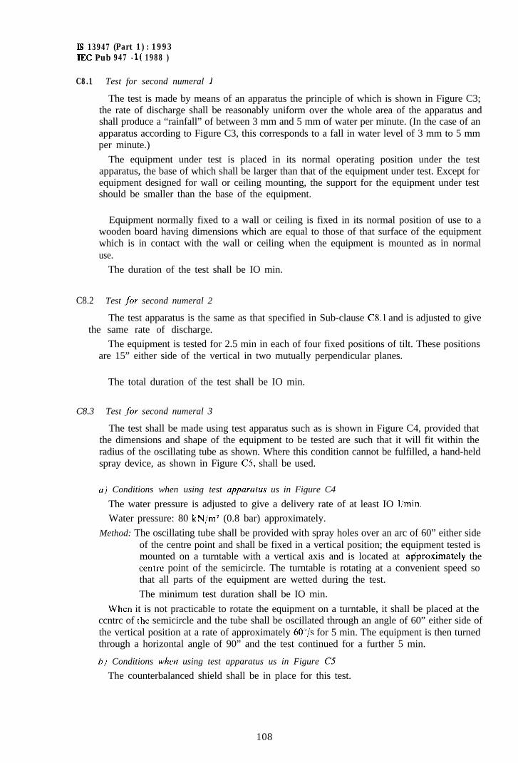
Is 13947 (Part 1) : 1993IEC Pub 947 - 1 ( 1988 )
C8.1 Test for second numeral 1
The test is made by means of an apparatus the principle of which is shown in Figure C3;the rate of discharge shall be reasonably uniform over the whole area of the apparatus andshall produce a “rainfall” of between 3 mm and 5 mm of water per minute. (In the case of anapparatus according to Figure C3, this corresponds to a fall in water level of 3 mm to 5 mmper minute.)
The equipment under test is placed in its normal operating position under the testapparatus, the base of which shall be larger than that of the equipment under test. Except forequipment designed for wall or ceiling mounting, the support for the equipment under testshould be smaller than the base of the equipment.
Equipment normally fixed to a wall or ceiling is fixed in its normal position of use to awooden board having dimensions which are equal to those of that surface of the equipmentwhich is in contact with the wall or ceiling when the equipment is mounted as in normaluse.
The duration of the test shall be IO min.
C8.2 Test ,for second numeral 2
The test apparatus is the same as that specified in Sub-clause C8.1 and is adjusted to givethe same rate of discharge.
The equipment is tested for 2.5 min in each of four fixed positions of tilt. These positionsare 15” either side of the vertical in two mutually perpendicular planes.
The total duration of the test shall be IO min.
C8.3 Test for second numeral 3
The test shall be made using test apparatus such as is shown in Figure C4, provided thatthe dimensions and shape of the equipment to be tested are such that it will fit within theradius of the oscillating tube as shown. Where this condition cannot be fulfilled, a hand-heldspray device, as shown in Figure C5, shall be used.
u) Conditions when using test upparutus us in Figure C4
The water pressure is adjusted to give a delivery rate of at least IO l/min.Water pressure: 80 kN/m2 (0.8 bar) approximately.
Method: The oscillating tube shall be provided with spray holes over an arc of 60” either sideof the centre point and shall be fixed in a vertical position; the equipment tested ismounted on a turntable with a vertical axis and is located at aIjproximately theccntre point of the semicircle. The turntable is rotating at a convenient speed sothat all parts of the equipment are wetted during the test.The minimum test duration shall be IO min.
When it is not practicable to rotate the equipment on a turntable, it shall be placed at theccntrc of the semicircle and the tube shall be oscillated through an angle of 60” either side ofthe vertical position at a rate of approximately 6O”/s for 5 min. The equipment is then turnedthrough a horizontal angle of 90” and the test continued for a further 5 min.
I’,) Conditions when using test apparatus us in Figure C5
The counterbalanced shield shall be in place for this test.
108
IS 13947 (Part 1) : 1993IEC Pub 947 - 1 ( 1988 )
The water pressure is adjusted to give a delivery rate of 10 l/min + 0.5 l/min (pressureapproximately 80- 100 kN/m’ (0.8- 1 .O bar)).
The test duration shall be 1 min per m* of calculated surface area(excluding any mounting surface) with a minimum duration of 5 min.
Nore. - For the purpose of this test, the surface area of the equipment is calculated+ 10%.
C8.4 Test for second numeral 4
of the enclosure
with an accuracy of
The conditions for deciding whether the apparatus of Figure C4 or that of Figure C5should be used are the same as those stated in Sub-clause C8.3.
a,i Using the apparatus of Figure C4
The oscillating tube shall have holes drilled over the whole 180” of the semicircle. The testduration. rate of oscillation and ivater pressure are as given in Sub-clause C8.3a).
The support for the equipment under test shall be perforated so as to avoid acting as abaffle and the equipment shall be sprayed from every direction by oscillating the tube tothe limit of its travel in each direction.
b) Using the uppuratus of Figure CS
The counterbalanced shield is removed from the spray nozzle and the equipment issprayed from all practicable directions.The rate of water delivery and the spraying time per unit area shall be as specified inSub-clause C8.3b).
C8.5 Test for second numeral 5
The test is made by spraying the equipment from all practicable directions with a stream ofwater from a standard test nozzle as shown in Figure C6. The conditions to be observed areas follows :
nozzle internal diameter: 6.3 mmdelivery rate: 12.5 l/min 55%water pressure * at the nozzle: approximately 30 kN/m’ (0.3 bar)test duration per m* of surface area of equipment: 1 minminimum test duration: 3 mindistance from nozzle to equipment surface: approximately 3 m. (This distance may bereduced if necessary to ensure proper wetting when spraying upwards.)
* The pressure should be adjusted to achieve the specified delivery rate. At 30 kN/m2 the water should rise freely fora vertical distance of approximately 2.5 m above the nozzle.
C8.6 Test for second numerul 6
The test is made by spraying the equipment from all practicable directions with a stream ofwater from a standard test nozzle as shown in Figure C6. The conditions to be observed areas follows :
-~- internal diameter of the nozzle: 12.5 mm- delivery rate : 100 l/min f 5%~ water pressure * at the nozzle: approximately 100 kN/m’ (1 bar)
* The pressure should be adjusted to achieve &e specified delivery rate. At 100 kN/m’ the water should rise freelyfor a vertical distance of approximately 8 m above the nozzle.
109
IS 13947 (Part 1) : 1993IEC Pub 947 - 1 ( 1988 )
- test duration per mz of surface area of equipment: 1 min
-- minimum test duration: 3 min
- distance from the nozzle to the equipment surface: approximately 3 m.
CS.1 Test for second numeral 7
The test is made by completely immersing the equipment in water so that the followingconditions are satisfied :
a) the surface of the water shall be at least 150 mm above the highest point of theequipment;
h) the lowest portion of the equipment shall be at least 1 m below the surface of thewater;
c) the duration of the test shall be at least 30 min;
d) the water temperature shall not differ from that of the equipment by more than 5 “C.
C8.8 Test .for second numeral 8
The test conditions shall be at least as severe as those prescribed in Sub-clause C8.7 andunder no circumstance shall water enter into the equipment.
C8.9 Stute of’ the equipment qfier the lest5
After testing in accordance with the appropriate requirements of Sub-clauses (28.1 to C8.8the external surfaces should be dried, and then the equipment shall be inspected for ingress ofwater.
The evaluation of harmful ingress of water depends on the dimensions of the equipment,and it is not possible to establish a general method suitable for all types of enclosures.
For Sub-clauses C8.1 to C8.7, if any water has entered, it shall not:
---- be sufficient to interfere with satisfactory operation of the equipment;
-- reach live parts or windings not designed to operate when wet;
accumulate near the conduit hole (cable entry) or enter the cable.
Where’ihe water ingress could raise doubts as to the functioning of the equipment adielectric test with reduced value shall be effected (e.g. a minimum of 50% of the dielectrictest voltage). If the equipment is provided with drain holes it shall be proved by inspectionthat any water which enters does not accumulate and that it drains away without doing anyharm to the equipment.
For Sub-clause (X.8, no water shall enter the equipment. Compliance is verified by visualinspection.
1 1 0
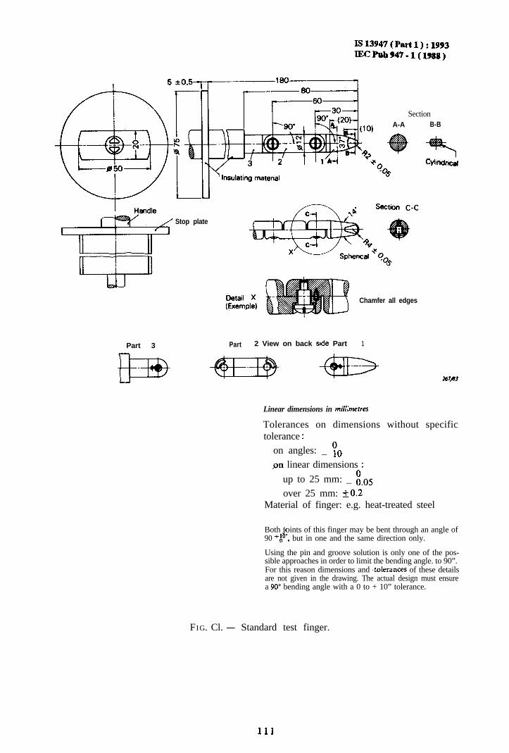
Is13947(Pfut1):1993IECPub947-l(1988)
SectionA-A B-B
Stop plate
Chamfer all edges
Part 3 Part 2 View on back side Part 1
Linear dimensions in mill;metres
Tolerances on dimensions without specifictolerance :
on angles: _ 70pn linear dimensions :
up to 25 mm: _ i-05over 25 mm: +0.2
Material of finger: e.g. heat-treated steel
Both ‘oints of this finger may be bent through an angle ofd*90 ‘A , but in one and the same direction only.
Using the pin and groove solution is only one of the pos-sible approaches in order to limit the bending angle. to 90”.For this reason dimensions and ~tolerances of these detailsare not given in the drawing. The actual design must ensurea 90” bending angle with a 0 to + 10” tolerance.
FIG. Cl. - Standard test finger.
111
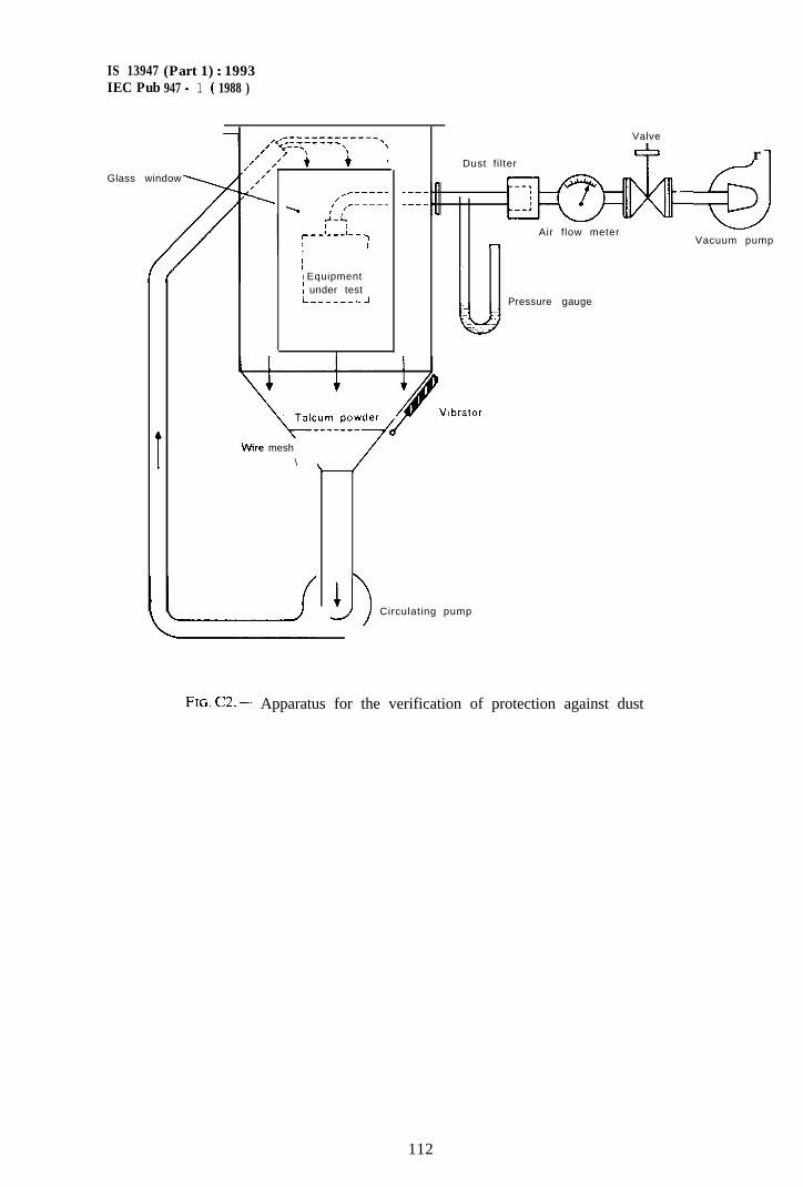
IS 13947 (Part 1) : 1993IEC Pub 947 - 1 ( 1988 )
Glass window
‘r____-_
/’ ______\ I’ ,’
1I
III EquipmentI under testL_-_____.J
__--_-__
Wire mesh\
3 Circulating pump
Valve
& rDust fi lter I
--3
ypyq-.__:
-
Air flow meter7 Vacuum pump
.-.
Pressure gauge
Vibrator
,
FIG. C2. - Apparatus for the verification of protection against dust
112
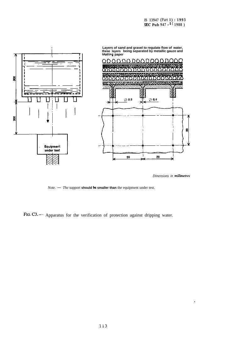
IS 13947 (Part 1) : 1993IEC Pub 947 - 1 ( 1988 )
iI I It --I-----C - I - - t
+----- ’---q
I II Iy---- ‘-- --I
-I
Layers of sand and gravel to regulate flow of water,these layers being separated by metallic gauze andblotiing paper
,-_;_a4
Dimensions in millimetres
Note. - The support should ix smaller than the equipment under test.
FIG- c3. - Apparatus for the verification of protection against dripping water.
.
113
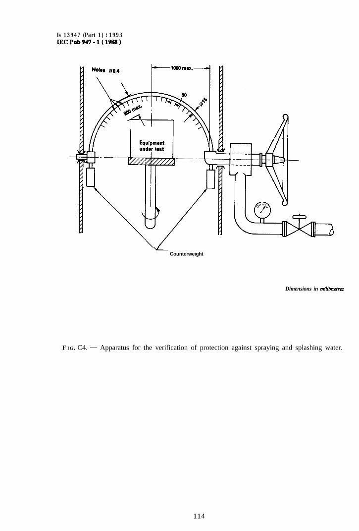
Is 13947 (Part 1) : 1993lECPub947.l(1988)
vCounterweight
Dimensions in millimetres
FIG. C4. - Apparatus for the verification of protection against spraying and splashing water.
114
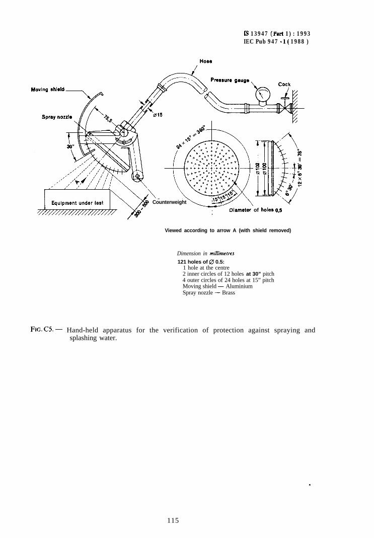
Ls 13947 (Yart 1) : 1993IEC Pub 947 - I( 1988 )
c3f CounterweightY#’Tame,.r of holea 0,s
Viewed according to arrow A (with shield removed)
Dimension in milhetres
121 holes of 0 0.5:1 hole at the centre2 inner circles of 12 holes at 30” pitch4 outer circles of 24 holes at 15” pitchMoving shield - AluminiumSpray nozzle - Brass
FE. C5. - Hand-held apparatus for the verification of protection against spraying andsplashing water.
115
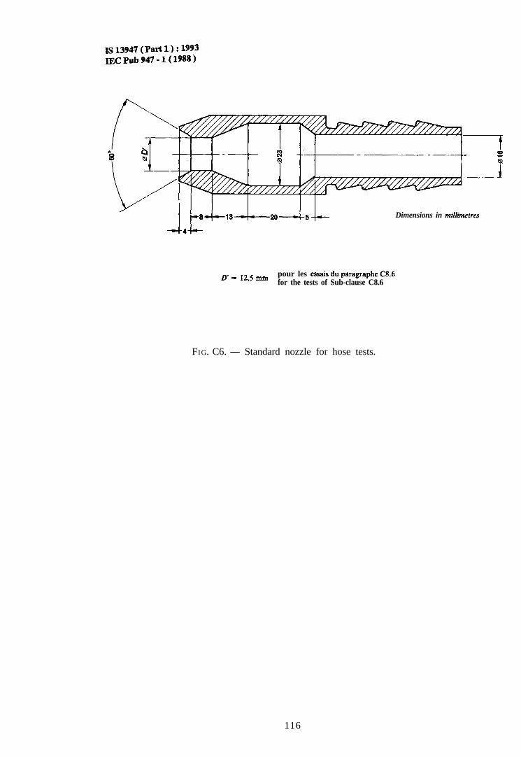
1s13947(Pati1):1993IJKPub947-l(1988)
1 i_84--+-~-4-- Dimensions in milhnetres
D’=12’5 mm
pour les essais du paragaphe (3.6for the tests of Sub-clause C8.6
FIG. C6. - Standard nozzle for hose tests.
116
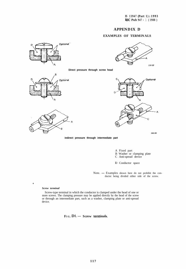
IS 13947 (Part 1) : 1993IEC Pub 947 - 1 ( 1988 )
APPENDIX D
EXAMPLES OF TERMINALS
Direct pressure through screw head
indirect pressure through intermediate part
A Fixed partB Washer or clamping plateC Anti-spread device
D Conductor space
Note. - Examples shown here do not prohibit the con-ductor being divided either side of the screw.
Screw terminal
Screw-type terminal in which the conductor is clamped under the head of one ormore screws. The clamping pressure may be applied directly by the head of the screwor through an intermediate part, such as a washer, clamping plate or anti-spreaddevice.
F I G. Dl. - Screw terrdnals.
1 1 7
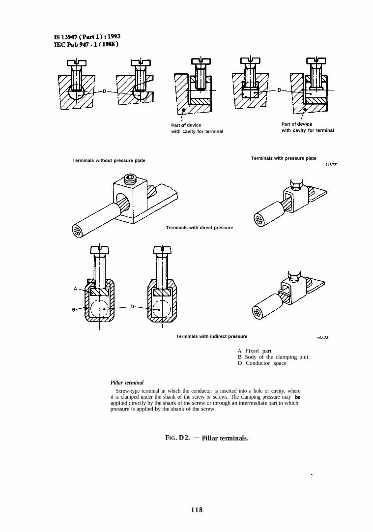
Is13947(Part1):1993IECPub947-l(1988)
Terminals without pressure plate
Part bf devicewith cavity for terminal
Part of davicewith cavity for terminal
Terminals with direct pressure
Terminals with pressure plateM/.“W
Terminals with indirect pressure J6.?/88
A Fixed partB Body of the clamping unitD Conductor space
Pillar terminalScrew-type terminal in which the conductor is inserted into a hole or cavity, where
it is clamped under the shank of the screw or screws. The clamping pressure may beapplied directly by the shank of the screw or through an intermediate part to whichpressure is applied by the shank of the screw.
,
FIG. D2. - Pillar terminals.
.
118
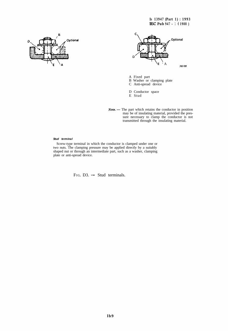
Is 13947 (Part 1) : 1993IEC Pub 947 - 1 ( 1988 )
Optional
‘E ‘ A563/88
A Fixed partB Washer or clamping plateC Anti-spread device
D Conductor spaceE Stud
iVore. - The part which retains the conductor in positionmay be of insulating material, provided the pres-sure necessary to clamp the conductor is nottransmitted through the insulating material.
Stud terminal
Screw-type terminal in which the conductor is clamped under one ortwo nuts. The clamping pressure may be applied directly by a suitablyshaped nut or through an intermediate part, such as a washer, clampingplate or anti-spread device.
FIG. D3. - Stud terminals.
lb9
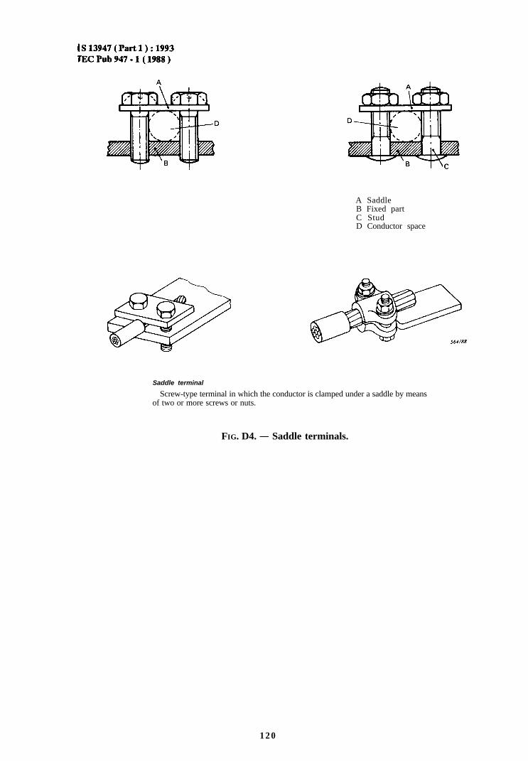
IS13947(Partl):1993TECPub947-l(1988)
A SaddleB Fixed partC StudD Conductor space
Saddle terminal
Screw-type terminal in which the conductor is clamped under a saddle by meansof two or more screws or nuts.
FIG. D4. - Saddle terminals.
120
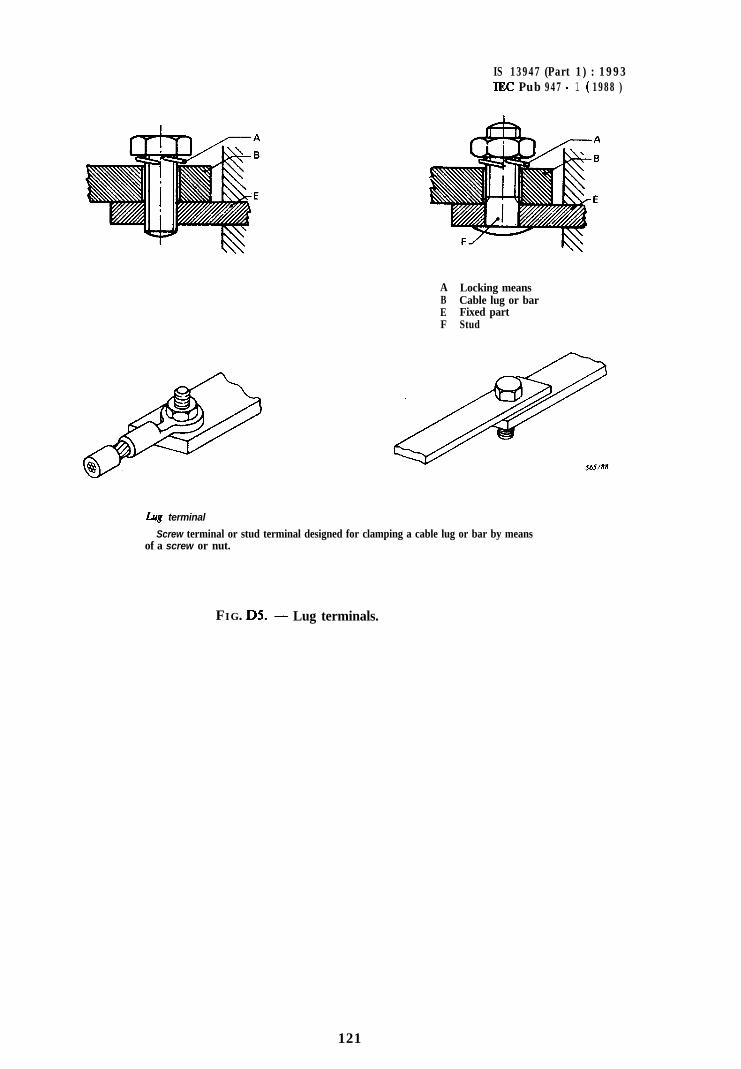
IS 13947 (Part 1) : 1993IEC Pub 947 - 1 ( 1988 )
ABEF
Locking meansCable lug or barFixed partStud
kg terminal
Screw terminal or stud terminal designed for clamping a cable lug or bar by meansof a screw or nut.
FIG. D5. - Lug terminals.
121
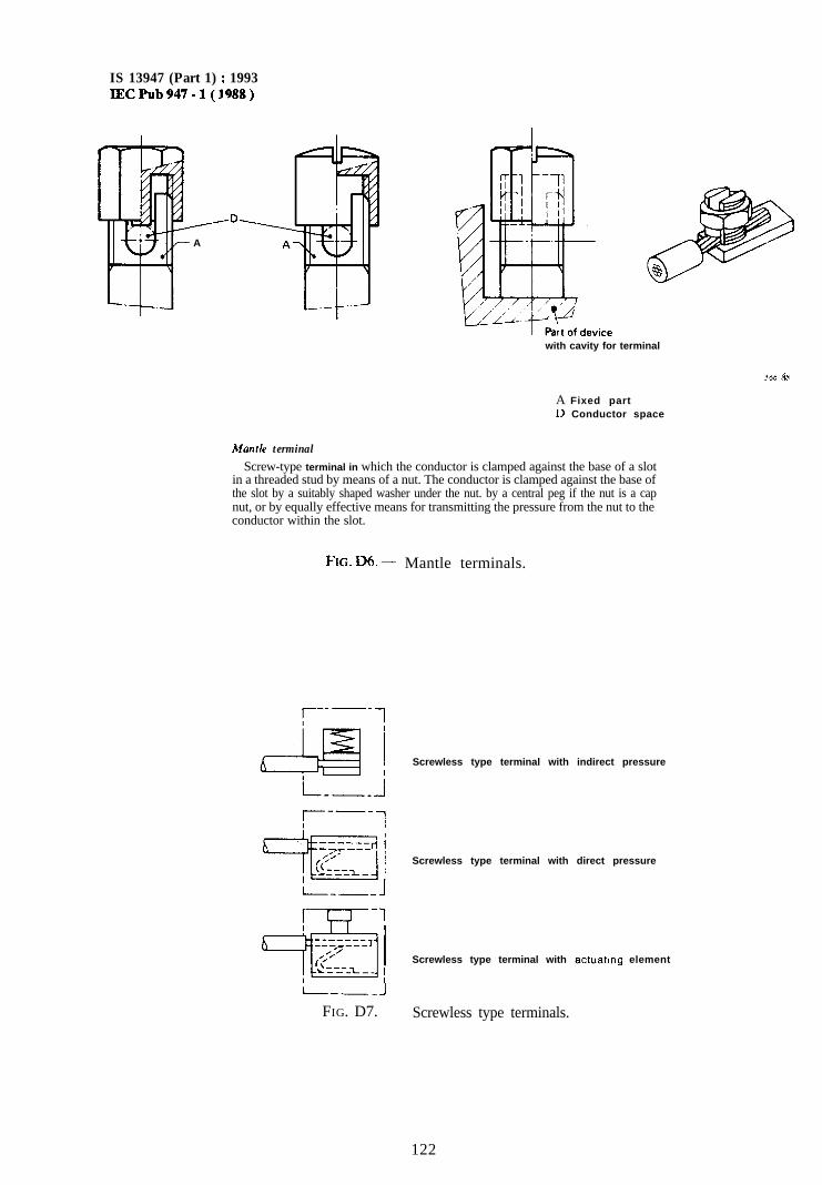
IS 13947 (Part 1) : 1993IECPub947-l(J988)
/-----D---A
with cavity for terminal
A Fixed partD Conductor space
Mantle terminal
Screw-type terminal in which the conductor is clamped against the base of a slotin a threaded stud by means of a nut. The conductor is clamped against the base ofthe slot by a suitably shaped washer under the nut. by a central peg if the nut is a capnut, or by equally effective means for transmitting the pressure from the nut to theconductor within the slot.
FIG. D6. - Mantle terminals.
I--_ -IFIG. D7.
Screwless type terminal with indirect pressure
Screwless type terminal with direct pressure
Screwless type terminal with actuating element
Screwless type terminals.
122
IS 13947 (Part 1) : 1993IEC Pub 947 - 1 ( 1988 )
APPENDIX E
DESCRIPTION OF A METHOD FOR ADJUSTING THE LOAD CIRCUIT
To adjust the load circuit to obtain the characteristics prescribed above, several methods may beapplicable ‘in practice. One of them is described below.
The principle is illustrated in Figure 8.The oscillatory frequency f of the transient recovery voltage and the value of the factor y are
essentially determined by the natural frequency and the damping of the load circuit. Since thesevalues are independent of the voltage and frequency applied to the circuit, the adjustment can bemade by energizing the load circuit from an a.c. power supply, the voltage and frequency of whichmay be different from those of the supply source utilized for the test of the equipment. The circuitis interrupted at a current zero by a diode, and the oscillations of the recovery voltage are observedon the screen of a cathode-ray oscilloscope, the sweep of which is synchronized with the frequencyof the power supply (see Figure El).
To permit reliable measurements to be made, the load circuit is energized by means of ahigh-frequency generator G giving a voltage suitable for the diode. The frequency of the generatoris chosen equal to:
a) 2 kHz for test currents up to and including 1 000 A;b) 4 kHz for test currents higher than 1 000 A.
Connected in series with the generator are:- a dropping resistor having a resistance value R, high with respect to the load circuit impedance
(R, 2 10 2, where Z = ,/w and where o = 2a. 2 000 s-l or = 21~. 4 000 s-i respec-tively) for cases a) and b) respectively;
- an instamaneously blocking switching diode B; switching diodes commonly used in computerssuch as diffused junction silicon switching diodes of not over 1 A forward rated current aresuitable for this application.
Due to the value of frequency of the generator G, the load circuit is practically purely inductiveand, at the instant of current zero, the applied voltage across the load circuit will be at its peakvalue. To ensure that the components of the load circuit are suitable, it must be checked on thescreen that the curve of the transient voltage at its initiation (point A in Figure El) has apractically horizontal tangent.
The actual value of the factor y is the ratio U,,/U,*; 17,~ is read on the screen, UIZ is read betweenthe ordinate of point A and the ordinate of the trace when the load circuit is no longer energizedby the generator (see Figure El).
When observing the transient voltage in the load circuit with no resistor R, or capacitor C, inparallel, one reads on the screen the natural oscillatory frequency of the load circuit. Care shouldbe taken that the capacitance of the oscilloscope or of its connecting leads does not influence theresonant frequency of the load circuit.
If that natural frequency exceeds the upper limit of the required valuef, the suitable values offrequency and factor y can be obtained by connecting in parallel capacitors C, and resistors R, ofappropriate values. The resistors R, shall be practically non-inductive.
It is recommended that, as a first step, each of the three phases of the load circuit be adjustedseparately. The adjustment is then completed by successively connecting, in each possible combi-I
123
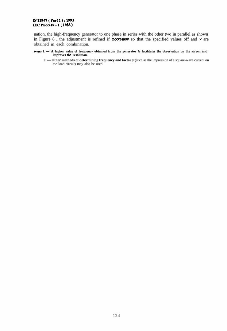
Is13947(Pact1):1993IECPub947-l(1988)
nation, the high-frequency generator to one phase in series with the other two in parallel as shownin Figure 8 ; the adjustment is refined if necessary so that the specified values off and y areobtained in each combination.
Notes 1. - A higher value of frequency obtained from the generator G facilitates the observation on the screen andimproves the resolution.
2. - Other methods of determining frequency and factor y (such as the impression of a square-wave current onthe load circuit) may also be used.
124
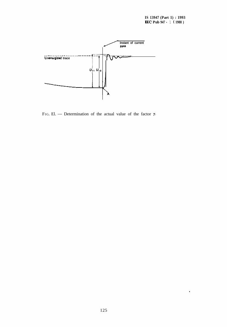
IS 13947 (Part 1) : 1993IEC Pub 947 - 1 ( 1988 )
Instant of currentZBIO
_____________________-_____ --- -._ - _______.Unenergited trace
ii -Ull uta
FIG. El. - Determination of the actual value of the factor y.
125
IS 13947 (Part 1) : 1993IEC Pub 947 - 1 ( 1988 )
APPENDIX F
DETERMINATION OF SHORT-CIRCUITOR TIME-CONSTANT
There is no method by which the short-circuit power-factor or time-constant can be determinedwith precision, but ‘for the purpose of this standard, the determination of the power-factor or thetime-constant of the test circuit may be made by one of the following methods:
POWER-FACTOR
Note. - Other methods for determining short-circuit power-factor are under consideration.
a) DETERMINATION OF SHORT-CIRCXJIT POWER-FACTOR
Method I. Determination from d.c. component
The angle Q, may be determined from the curve of the d.c. component of the asymmetricalcurrent wave between the instant of the short-circuit and the instant of contact separation asfollows :
1. To determine the time-constant L/R .from the formula for the d.c. component.
The formula for the d.c. component is:
w h e r e :
4 is the value of the d.c. component at the instant rI,, is the value of the d.c. component at the instant taken as time origin.L/R is the time-constant of the circuit, in secondst is the time, in seconds, taken from the initial instante is the base of Napierian logarithms
The time-constant L/R can be determined by:a) measuring the value of I,, at the instant of short-circuit and the value of id at another
instant t before contact separation,b) determining the value of e-R”L by dividing id by Zd0,c) determining the value of - x corresponding to the ratio id/&, from a table of values
of e-xThe value x then represents Rt/L, from which R/L is obtained.
2. To determine the angle v, from:
w = arc tan J+
where o is 2 K times the actual frequency.
This method should not be used when the currents are measured by current transformers, exceptif suitable precautions are taken to eliminate errors due to:- the time-constant of the transformer and its burden in relation to that of the primary
circuit ;
- magnetic saturation which can result from the transient flux conditions combined with possibleremanence.
Method II. Determination with pilot generator
When a pilot generator is used on the same shaft as the test generator, the voltage of the pilotgenerator on the oscillogram may be compared in phase first with the voltage of the test generatorand then with the current of the test generator.
126

IS 13947 (Part 1) : 1993IEC Pub 947 - 1 ( 1988 )
The difference between the phase angles between pilot generator voltage and main generatorvoltage on the one hand and pilot generator voltage and test generator current on the other handgives the phase angle between the voltage and current of the test generator, from which thepower-factor can be determined.
b) DETERMINATION OF SHORT-CIRCUIT TIME-CONSTANT (OSCILLOGRAPHIC METHOD)
The value of the time-constant is given by the abscissa corresponding to the ordinate 0.632 AZ ofthe ascending part of the curve of the oscillogram of calibration of the circuit (see Figure 14).
127
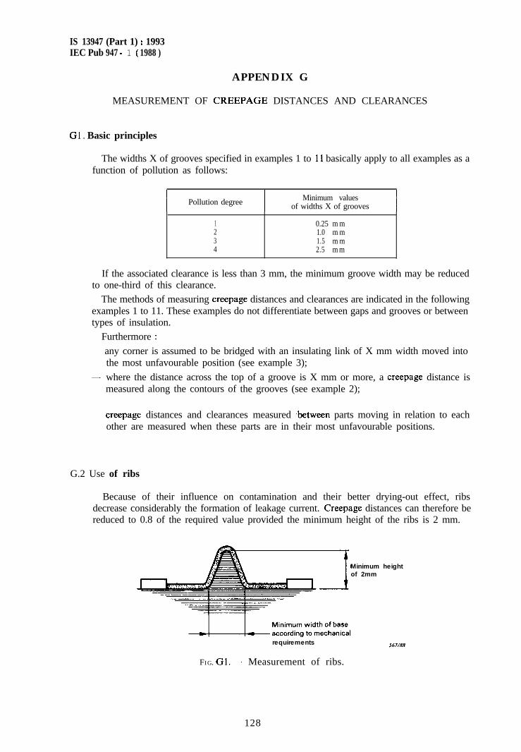
IS 13947 (Part 1) : 1993IEC Pub 947 - 1 ( 1988 )
APPENDIX G
MEASUREMENT OF CREEPAGE DISTANCES AND CLEARANCES
Gl . Basic principles
The widths X of grooves specified in examples 1 to 11 basically apply to all examples as afunction of pollution as follows:
I Pollution degreeI
Minimum valuesof widths X of grooves I
1 0.25 m m2 1.0 m m3 1.5 m m4 2.5 m m
If the associated clearance is less than 3 mm, the minimum groove width may be reducedto one-third of this clearance.
The methods of measuring creepage distances and clearances are indicated in the followingexamples 1 to 11. These examples do not differentiate between gaps and grooves or betweentypes of insulation.
Furthermore :
- any corner is assumed to be bridged with an insulating link of X mm width moved intothe most unfavourable position (see example 3);
- where the distance across the top of a groove is X mm or more, a creepage distance ismeasured along the contours of the grooves (see example 2);
- creepage distances and clearances measured .between parts moving in relation to eachother are measured when these parts are in their most unfavourable positions.
G.2 Use of ribs
Because of their influence on contamination and their better drying-out effect, ribsdecrease considerably the formation of leakage current. Creepage distances can therefore bereduced to 0.8 of the required value provided the minimum height of the ribs is 2 mm.
Minimum heightof 2mm
requirements
FIG. Gl. - Measurement of ribs.
567/6X
128
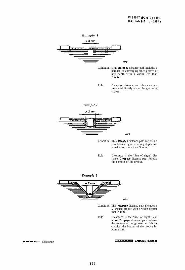
Is 13947 (Part 1) : 199IEC Pub 947 - 1 ( 1988 )
- - - - - Clearance B Creepage distany
Example I
<Xmm
/27/x/
Condition : This creepage distance path includes aparallel- or converging-sided groove ofany depth with a width less thanXmnl.
Rule : Creepage distance and clearance aremeasured directly across the groove asshown.
Example 2
Condition: This creepage distance path includes aparallel-sided groove of any depth andequal to or more than X mm.
Rule : Clearance is the “line of sight” dis-tance. Creepage distance path followsthe contour of the groove.
Example 3
Condition: This creepage distance path includes aV-shaped groove with a width greaterthan X mm.
Rule : Clearance is the “line of sight” dis-tance. Creepage distance path followsthe contour of the groove but “short-circuits” the bottom of the groove byX mm link.
129
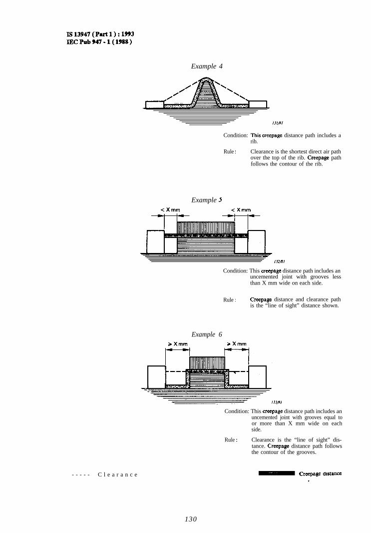
Is13947(Plut1):1993IECPub947-l(1988)
Example 4
Condition: This creepage distance path includes arib.
Rule : Clearance is the shortest direct air pathover the top of the rib. Creepage pathfollows the contour of the rib.
Example 5<Xmm <Xmm
-132/8l
Condition: This creepage distance path includes anuncemented joint with grooves lessthan X mm wide on each side.
Rule : Creepage distance and clearance pathis the “line of sight” distance shown.
Example 6aXmm *Xmm
Condition: This creepage distance path includes anuncemented joint with grooves equal toor more than X mm wide on eachside.
Rule : Clearance is the “line of sight” dis-tance. Creepage distance path followsthe contour of the grooves.
,
- - - - - C l e a r a n c e\ Creepage dtstance
130
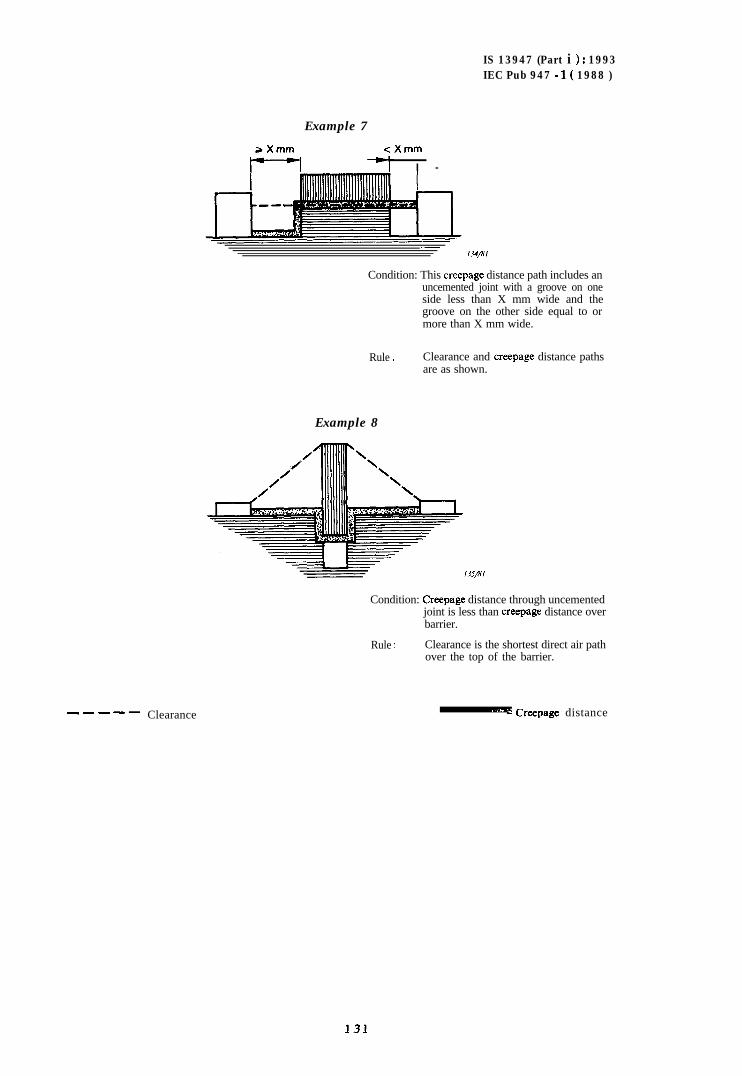
IS 13947 (Part i ) : 1993IEC Pub 947 - I( 1988 )
----- Clearance
Example 7
*Xmm <Xmm
I -
-/34/x/
Condition: This creepage distance path includes anuncemented joint with a groove on oneside less than X mm wide and thegroove on the other side equal to ormore than X mm wide.
Rule : Clearance and creepage distance pathsare as shown.
Example 8
Condition: Creepage distance through uncementedjoint is less than creepage distance overbarrier.
Rule : Clearance is the shortest direct air pathover the top of the barrier.
. . ._. 4 Creepage distance
131
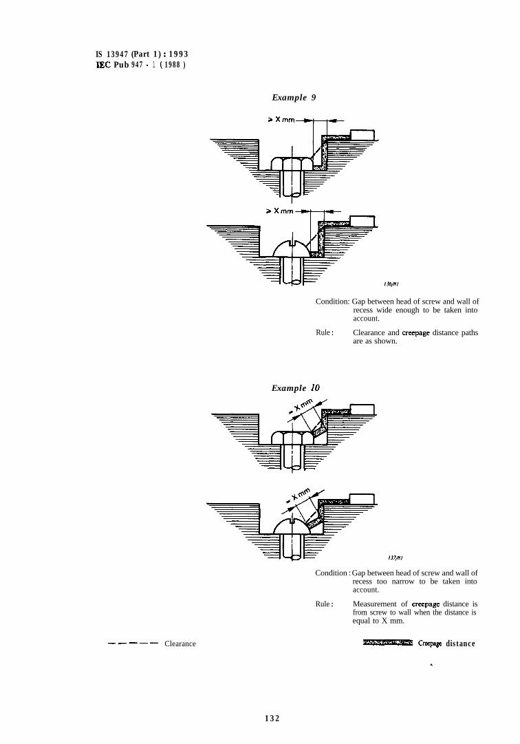
IS 13947 (Part 1) : 1993IEC Pub 947 - 1 ( 1988 )
- - - - - Clearance
Example 9
,
Condition: Gap between head of screw and wall ofrecess wide enough to be taken intoaccount.
Rule : Clearance and creepage distance pathsare as shown.
Example 10
137/a%,
Condition : Gap between head of screw and wall ofrecess too narrow to be taken intoaccount.
Rule : Measurement of creepage distance isfrom screw to wall when the distance isequal to X mm.
Creepage distance
132
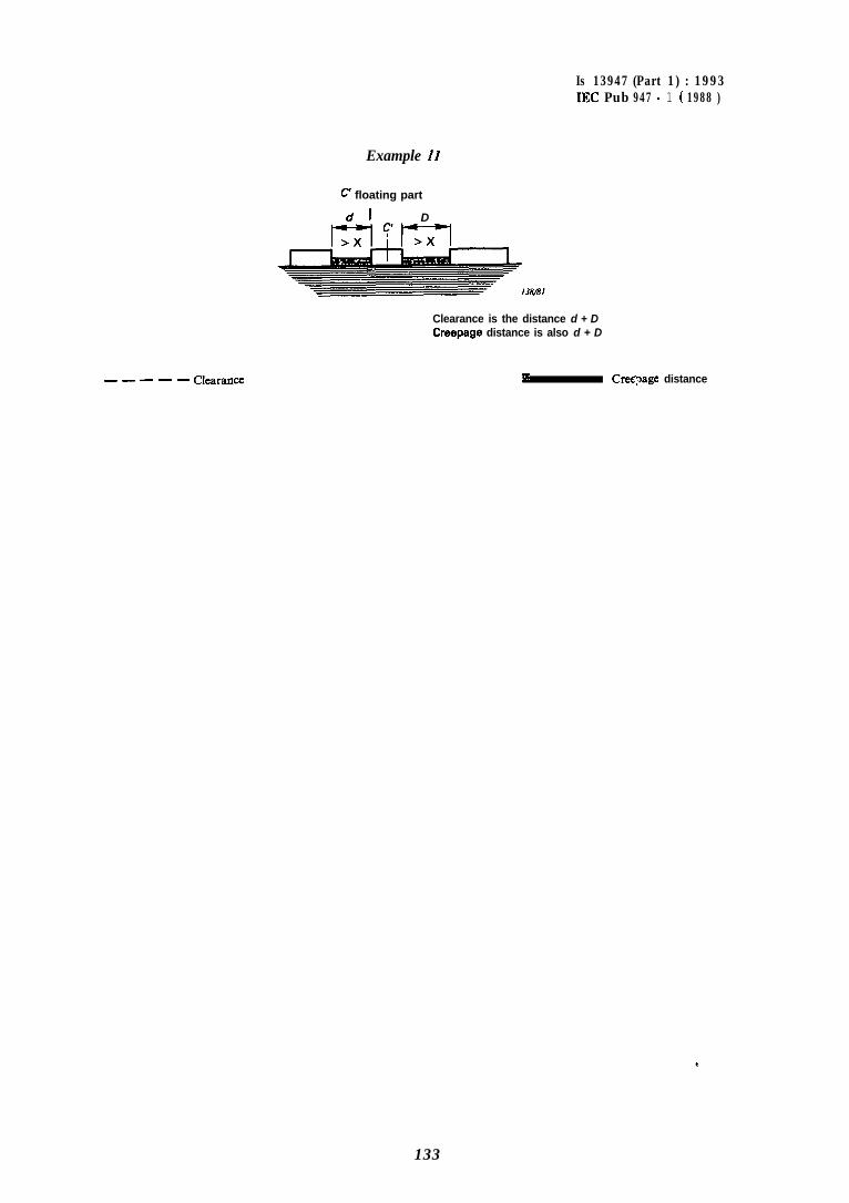
- - - - - Clearance
Is 13947 (Part 1) : 1993IEC Pub 947 - 1 ( 1988 )
Example II
C floating part
d 1 D
Clearance is the distance d + DCreepage distance is also d + D
* Cre@age distance
133
IS 13947 (Part 1) : 1993IEC Pub 947 - 1 ( I988 )
APPENDIX H
CORRELATION BETWEEN THE NOMINAL VOLTAGEOF THE SUPPLY SYSTEM AND THE RATED IMPULSE
WITHSTAND VOLTAGE OF EQUIPMENT
INTRODUCTION
This appendix is intended to give the necessary information concerning the choice of equipmentfor use in a circuit within an electrical system or part thereof.
Tables Hl and H2 provide examples of the correlation between nominal supply system voltagesand the corresponding rated impulse withstand voltage of equipment.
The values of rated impulse withstand voltage given in Tables HI and H2 are based on theperformance characteristics of surge arresters. Values of Table Hl are based on characteristics inaccordance with I E C Publication 99-l ; values of Table H2 are based on characteristics of surgearresters having a ratio of sparkover voltage to rated voltage lower than that given in J E CPublication 99-l.
It should also be recognized that control of overvoltages with respect to the values in Tables Hland H2 can also be achieved by conditions in the supply system such as the existence of a suitableimpedance or cable feed.
In such cases when the control of overvoltages is achieved by means other than surge arresters,guidance for the correlation between the nominal supply system voltage and the equipment ratedimpulse withstand voltage is given in I E C Publication 364-4-443.
134
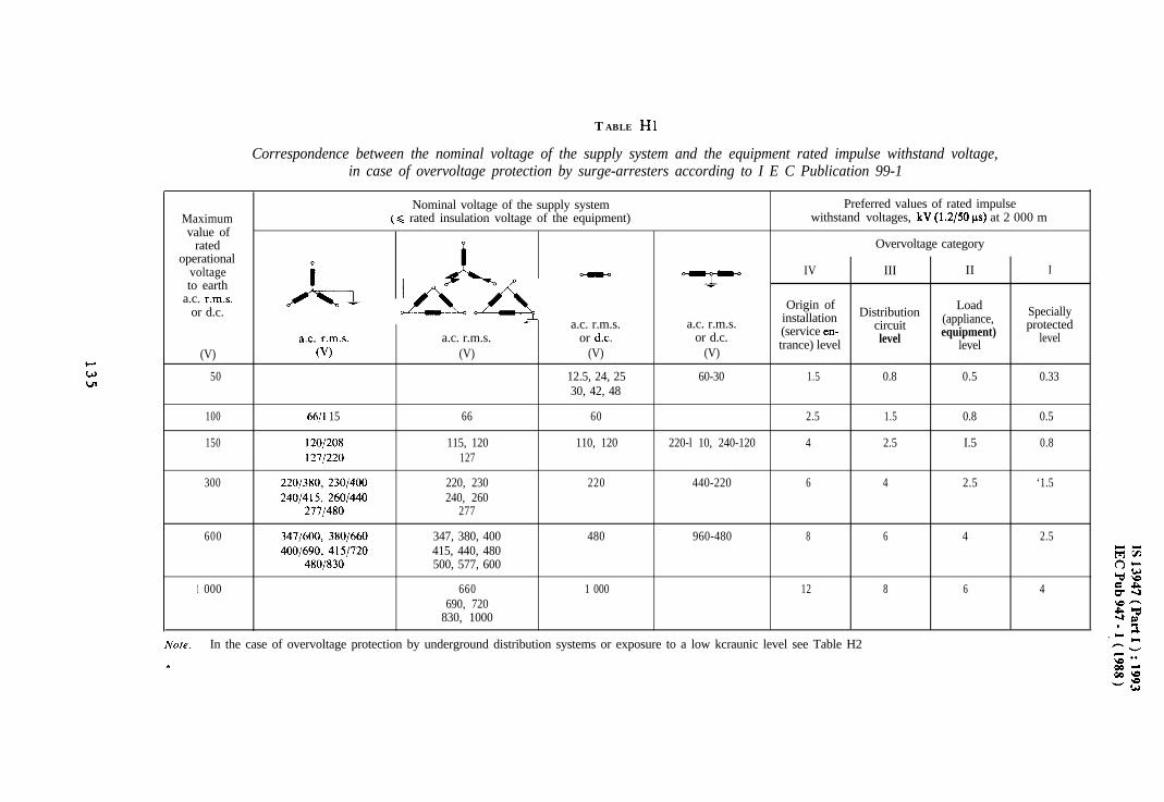
TABLE Hl
Correspondence between the nominal voltage of the supply system and the equipment rated impulse withstand voltage,in case of overvoltage protection by surge-arresters according to I E C Publication 99-1
Maximumvalue of
ratedoperational
voltageto earth
a.c. r.m.s.or d.c.
(V)
Nominal voltage of the supply system(C rated insulation voltage of the equipment)
A
A hOI/_a -7 a.c. r.m.s.
a.c. r.m.s. a.c. r.m.s. or de.0’) (V) (V)
7
a.c. r.m.s.or d.c.
(V)
Preferred values of rated impulsewithstand voltages, kV (1.2/50 ps) at 2 000 m
Overvoltage category
IV III II I
Origin of Distribution Load Speciallyinstallation circuit (appliance, protected(service en-level equipment) leveltrance) level level
50 12.5, 24, 25 60-30 1.5 0.8 0.5 0.3330, 42, 48
100 66/l 15 66 60 2.5 1.5 0.8 0.5
150 120/208 115, 120 110, 120 220-l 10, 240-120 4 2.5 I.5 0.81271220 127
300 2201380, 230/400 220, 230 220 440-220 6 4 2.5 ‘1.52401415, 2601440 240, 260
277/480 277
600 3471600, 380/660 347, 380, 400 480 960-480 8 6 4 2.54001690, 4151720 415, 440, 480
480/830 500, 577, 600
1 000 660 1 000 12 8 6 4690, 720
830, 1000
Nore. - In the case of overvoltage protection by underground distribution systems or exposure to a low kcraunic level see Table H2
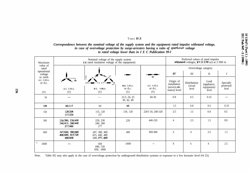
TABLE H Z
Correspondence between the nominal voltage of the supply system and the equipment rated impulse withstand voltage,in case of overvoltage protection by surge-arresters having a ratio of spatkover voltage
to rated voltage lower than in I E C Publication 99-l
Nominal voltage of the supply system Preferred values of rated impulseMaximum (Q rated insulation voltage of the equipment) Gthstand voltages, kV (1.2/50 us) at 2 000 mvalue of
rated
A
Overvoltage categoryoperational
voltage
A AA_ -
Y IVIII II I
to eartha.c. r.m.s. Origin of Loador d.c. Distributioninstallation (appliance, SpeciallyT a.c. r.m.s. a.c. r.m.s.
(service en- circuit equipment) protecteda.c. r.m.s. ac. r.m.s. or d.c. or d.c.
trance) level level level(V) (V) (V) (V) (V)
level
50 - - 12.5, 24, 25 60-30 0.8 0.5 0.33 -30, 42, 48
IO0 66/115 66 60 - 1.5 0.8 0.5 0.33
150 120/208 115, 120 110, 120 220-l 10, 240-120 2.5 1.5 0.8 0.51271220 127
300 2201380, 2301400 220, 230 220 440-220 4 2.5 1.5 0.8240/415, 2601440 240, 260
2771480 277
600 3471600, 3801660 347, 380, 400 480 960-480 6 4 2.5 1.5400/690, 4151720 415, 440, 480
480/830 500, 577;600
L 1000 - 660 1000 - 8 6 4 2.5690, 720
830, 1000
Note. - Table H2 may also apply in the case of overvoltage protection by underground distribution systems or exposure to a low keraunic level (< 25).
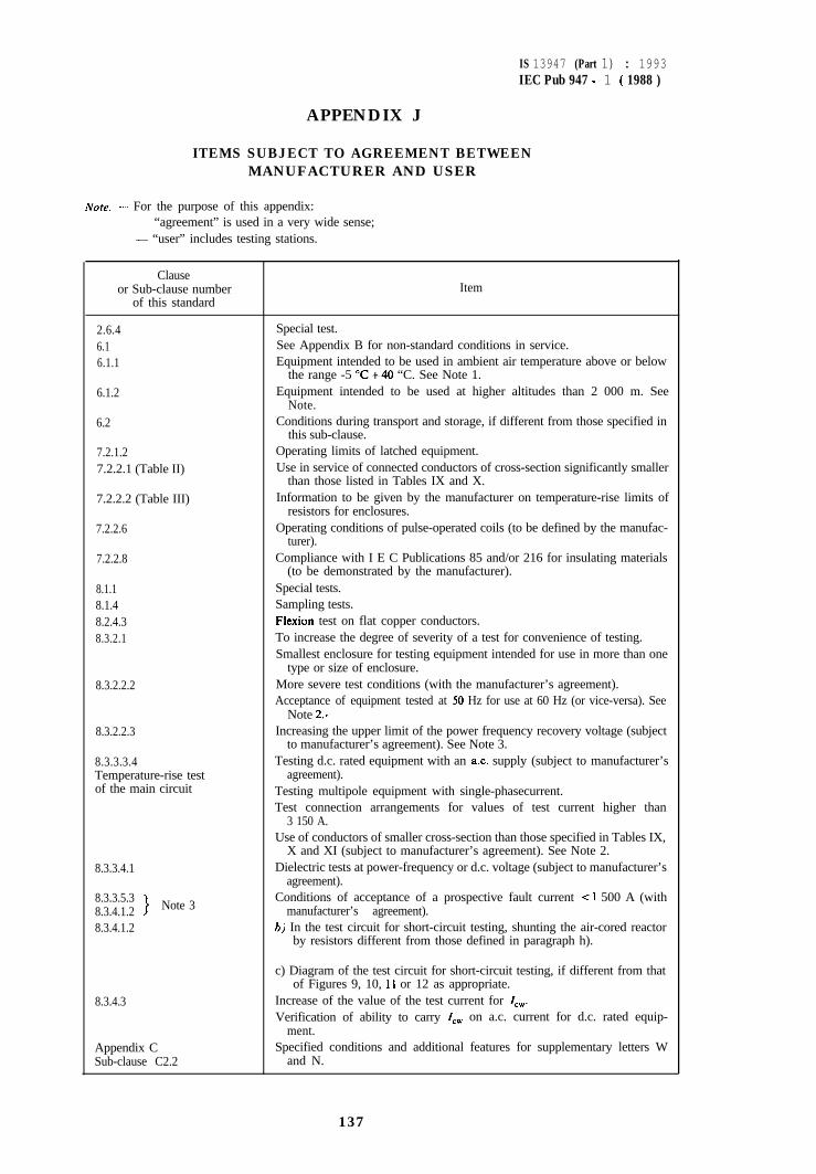
IS 13947 (Part 1) : 1993IEC Pub 947 - 1 ( 1988 )
APPENDIX J
ITEMS SUBJECT TO AGREEMENT BETWEENMANUFACTURER AND USER
Note. - For the purpose of this appendix:- “agreement” is used in a very wide sense;- “user” includes testing stations.
Clauseor Sub-clause number
of this standardItem
2.6.46.16.1.1
6.1.2
6.2
7.2.1.27.2.2.1 (Table II)
7.2.2.2 (Table III)
7.2.2.6
7.2.2.8
8.1.18.1.48.2.4.38.3.2.1
8.3.2.2.2
8.3.2.2.3
8.3.3.3.4Temperature-rise testof the main circuit
Special test.See Appendix B for non-standard conditions in service.Equipment intended to be used in ambient air temperature above or below
the range -5 “C +40 “C. See Note 1.Equipment intended to be used at higher altitudes than 2 000 m. See
Note.Conditions during transport and storage, if different from those specified in
this sub-clause.Operating limits of latched equipment.Use in service of connected conductors of cross-section significantly smaller
than those listed in Tables IX and X.Information to be given by the manufacturer on temperature-rise limits of
resistors for enclosures.Operating conditions of pulse-operated coils (to be defined by the manufac-
turer).Compliance with I E C Publications 85 and/or 216 for insulating materials
(to be demonstrated by the manufacturer).Special tests.Sampling tests.Flexion test on flat copper conductors.To increase the degree of severity of a test for convenience of testing.Smallest enclosure for testing equipment intended for use in more than one
type or size of enclosure.More severe test conditions (with the manufacturer’s agreement).Acceptance of equipment tested at 50 Hz for use at 60 Hz (or vice-versa). See
Note 2..Increasing the upper limit of the power frequency recovery voltage (subject
to manufacturer’s agreement). See Note 3.Testing d.c. rated equipment with an ac. supply (subject to manufacturer’s
agreement).Testing multipole equipment with single-phasecurrent.Test connection arrangements for values of test current higher than
3 150 A.Use of conductors of smaller cross-section than those specified in Tables IX,
X and XI (subject to manufacturer’s agreement). See Note 2.8.3.3.4.1 Dielectric tests at power-frequency or d.c. voltage (subject to manufacturer’s
agreement).8.3.3.5.38.3.4.1.2 > Note 3
Conditions of acceptance of a prospective fault current < 1 500 A (withmanufacturer’s agreement).
8.3.4.1.2 h) In the test circuit for short-circuit testing, shunting the air-cored reactorby resistors different from those defined in paragraph h).
8.3.4.3
Appendix CSub-clause C2.2
c) Diagram of the test circuit for short-circuit testing, if different from thatof Figures 9, 10, 11 or 12 as appropriate.
Increase of the value of the test current for I,,,,.Verification of ability to carry Icw on a.c. current for d.c. rated equip-
ment.Specified conditions and additional features for supplementary letters W
and N.
137
,
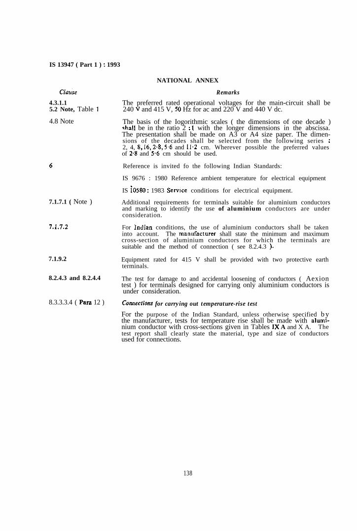
IS 13947 ( Part 1 ) : 1993
Clause
4.3.1.15.2 Note, Table 1
4.8 Note
6
7.1.7.1 ( Note )
7.1.7.2
7.1.9.2
8.2.4.3 and 8.2.4.4
8.3.3.3.4 ( Para 12 )
NATIONAL ANNEX
Remarks
The preferred rated operational voltages for the main-circuit shall be240 V and 415 V, 50 Hz for ac and 220 V and 440 V dc.
The basis of the Iogorithmic scales ( the dimensions of one decade )shall be in the ratio 2 : I with the longer dimensions in the abscissa.The presentation shall be made on A3 or A4 size paper. The dimen-sions of the decades shall be selected from the following series :2, 4, 8, 16, 2.8, 5.6 and 1 l-2 cm. Wherever possible the preferred valuesof 2.8 and 5.6 cm should be used.
Reference is invited fo the following Indian Standards:
IS 9676 : 1980 Reference ambient temperature for electrical equipment
IS iO580 : 1983 Service conditions for electrical equipment.
Additional requirements for terminals suitable for aluminium conductorsand marking to identify the use of aluminium conductors are underconsideration.
For Indian conditions, the use of aluminium conductors shall be takeninto account. The manufacturer shall state the minimum and maximumcross-section of aluminium conductors for which the terminals aresuitable and the method of connection ( see 8.2.4.3 ).
Equipment rated for 415 V shall be provided with two protective earthterminals.
The test for damage to and accidental loosening of conductors ( Aexiontest ) for terminals designed for carrying only aluminium conductors isunder consideration.
Conrtecfions for carrying out temperature-rise test
For the purpose of the Indian Standard, unless otherwise specified b ythe manufacturer, tests for temperature rise shall be made with alumi-nium conductor with cross-sections given in Tables 1X A and X A. Thetest report shall clearly state the material, type and size of conductorsused for connections.
138
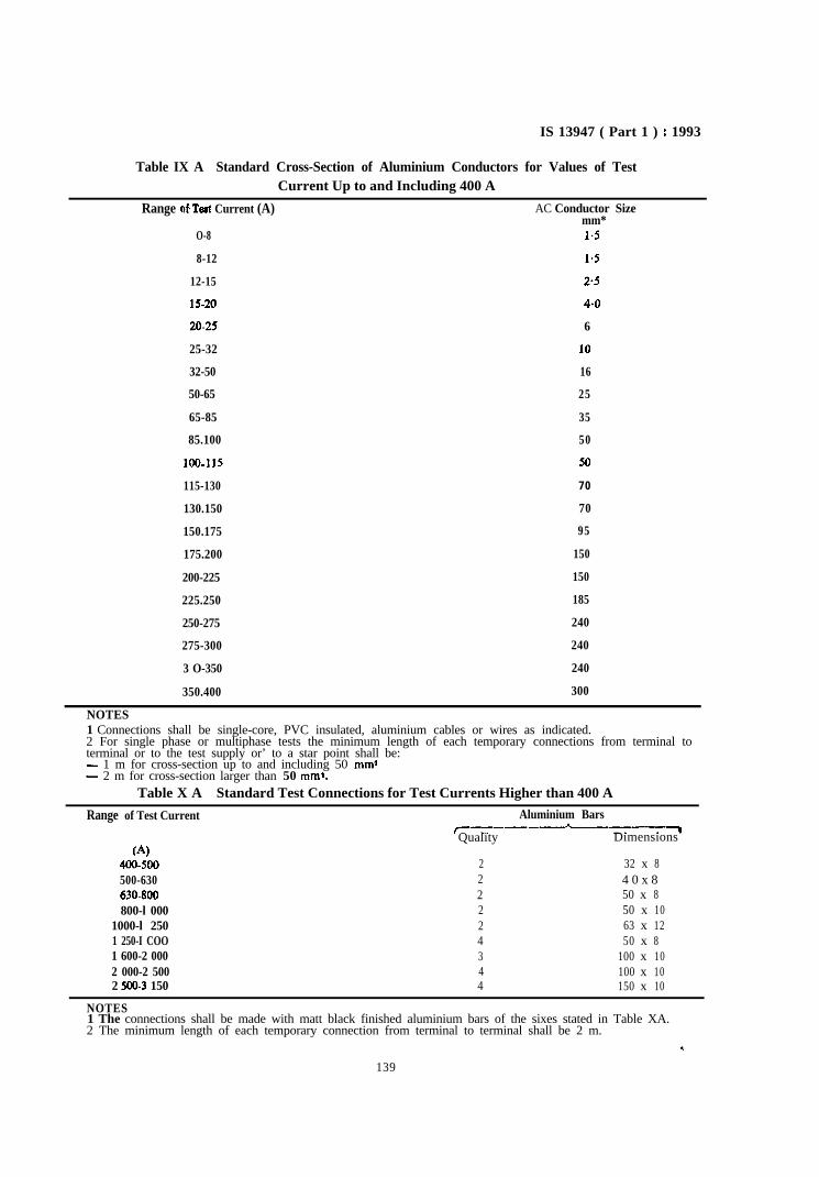
IS 13947 ( Part 1 ) : 1993
Table IX A Standard Cross-Section of Aluminium Conductors for Values of TestCurrent Up to and Including 400 A
Range nC Test Current (A) AC Conductor Sizemm*
O-8 1.5
8-12 1.5
12-15 2.5
15-20 4.0
20-25 6
25-32 10
32-50 16
50-65 25
65-85 35
85.100 50
100-115
115-130
130.150
150.175
175.200
50
70
70
95
150
200-225 150
225.250 185
250-275 240
275-300 240
3 O-350 240
350.400 300
NOTES1 Connections shall be single-core, PVC insulated, aluminium cables or wires as indicated.2 For single phase or multiphase tests the minimum length of each temporary connections from terminal toterminal or to the test supply or’ to a star point shall be:- 1 m for cross-section up to and including 50 mm9- 2 m for cross-section larger than 50 mm%
Table X A Standard Test Connections for Test Currents Higher than 400 A
Range of Test Current
(4400-500500-630630.800800-l 000
1000-l 2501 250-I COO1 600-2 0002 000-2 5002 500-3 150
Aluminium BarsT-_----Quality
,---vDimensions
2 32 x 82 4 0 x 82 50 x 82 50 x 102 63 x 124 50 x 83 100 x 104 100 x 104 150 x 10
,
NOTES1 The connections shall be made with matt black finished aluminium bars of the sixes stated in Table XA.2 The minimum length of each temporary connection from terminal to terminal shall be 2 m.
139


![ISSN 2185-2839 (print) ISSN 2185-2847 (online ...cse.csusb.edu/egomez/ref/140-190-1-PB.pdf · and graph theory. Multidimensional entropy has been used in networking [46] for network](https://img.pdfslide.us/doc/110x75/5f039a617e708231d409ddd8/issn-2185-2839-print-issn-2185-2847-online-csecsusbeduegomezref140-190-1-pbpdf.jpg)