Embed Size (px)
Citation preview

Sydney One ProjectCrone Partners Pty Limited02-Jul-2015Doc No. 60430261-IMP-A
Building ServicesInfrastructure Management
PlanSydney One Project, Sydney

AECOM Sydney One ProjectBuilding Services Infrastructure Management Plan
\\ausyd1fp001\Projects\_Proposals\2015\Buildings\OPP-354743 1 Alfred St Sydney\Services Templates\Sydney One Project - InfrastructureManagement Plan - Rev - A.docxRevision A – 02-Jul-2015Prepared for – Crone Partners Pty Limited – ABN: 80095989272
Building Services Infrastructure Management PlanSydney One Project, Sydney
Client: Crone Partners Pty Limited
ABN: 80095989272
Prepared byAECOM Australia Pty LtdLevel 21, 420 George Street, Sydney NSW 2000, PO Box Q410, QVB Post Office NSW 1230, AustraliaT +61 2 8934 0000 F +61 2 8934 0001 www.aecom.comABN 20 093 846 925
02-Jul-2015
AECOM in Australia and New Zealand is certified to the latest version of ISO9001, ISO14001, AS/NZS4801 and OHSAS18001.
© AECOM Australia Pty Ltd (AECOM). All rights reserved.
AECOM has prepared this document for the sole use of the Client and for a specific purpose, each as expressly stated in the document. No otherparty should rely on this document without the prior written consent of AECOM. AECOM undertakes no duty, nor accepts any responsibility, to anythird party who may rely upon or use this document. This document has been prepared based on the Client’s description of its requirements andAECOM’s experience, having regard to assumptions that AECOM can reasonably be expected to make in accordance with sound professionalprinciples. AECOM may also have relied upon information provided by the Client and other third parties to prepare this document, some of whichmay not have been verified. Subject to the above conditions, this document may be transmitted, reproduced or disseminated only in its entirety.

AECOM Sydney One ProjectBuilding Services Infrastructure Management Plan
\\ausyd1fp001\Projects\_Proposals\2015\Buildings\OPP-354743 1 Alfred St Sydney\Services Templates\Sydney One Project - InfrastructureManagement Plan - Rev - A.docxRevision A – 02-Jul-2015Prepared for – Crone Partners Pty Limited – ABN: 80095989272
Quality InformationDocument Building Services Infrastructure Management Plan
Ref 60430261-IMP-A
Date 02-Jul-2015
Prepared by Adam Magee
Reviewed by Eoin Loughnane
Revision History
Revision Revision Date DetailsAuthorised
Name/Position Signature
A 2 July 2015 Final Issue Adam MageePrincipal Vertical Transportation Engineer

AECOM Sydney One ProjectBuilding Services Infrastructure Management Plan
\\ausyd1fp001\Projects\_Proposals\2015\Buildings\OPP-354743 1 Alfred St Sydney\Services Templates\Sydney One Project - InfrastructureManagement Plan - Rev - A.docxRevision A – 02-Jul-2015Prepared for – Crone Partners Pty Limited – ABN: 80095989272
Table of ContentsProject Appreciation 11.0 Infrastructure Impact 12.0 Electrical Services 1
2.1 Substation 12.1.1 Requirements 12.1.2 Configuration 1
2.2 Ausgrid 32.3 NBN 4
2.3.1 Tower A 42.3.2 Tower B 5
2.4 Telstra 62.4.1 Tower A 62.4.2 Tower B 7
3.0 Hydraulic Services 83.1 Sanitary Plumbing and Sewer Drainage 8
3.1.1 Connection Point 83.1.2 Basement Levels 83.1.3 Tower A - Residential 83.1.4 Tower B - Hotel 8
3.2 Stormwater Drainage 93.2.1 Connection Point 93.2.2 Basement Levels 93.2.3 Tower A - Residential 93.2.4 Tower B - Hotel 9
3.3 Sub-soil Drainage 103.3.1 Connection Point 103.3.2 Basement Levels 103.3.3 Tower A - Residential 103.3.4 Tower B - Hotel 10
3.4 Potable Water Service 113.4.1 Connection Point 113.4.2 Metering 113.4.3 Basement Levels 113.4.4 Tower A - Residential 123.4.5 Tower B - Hotel 12
3.5 Potable Hot Water Service 123.5.1 Basement Levels 123.5.2 Metering 123.5.3 Basement Levels 123.5.4 Tower A - Residential 133.5.5 Tower B - Hotel 13
3.6 Gas Services 143.6.1 Basement Levels 143.6.2 Metering 143.6.3 Tower A - Residential 153.6.4 Tower B - Hotel 15

AECOM Sydney One ProjectBuilding Services Infrastructure Management Plan
\\ausyd1fp001\Projects\_Proposals\2015\Buildings\OPP-354743 1 Alfred St Sydney\Services Templates\Sydney One Project - InfrastructureManagement Plan - Rev - A.docxRevision A – 02-Jul-2015Prepared for – Crone Partners Pty Limited – ABN: 80095989272
1
Project AppreciationSydney One Project located at 1 Alfred St, 19-31 Pitt St and 31A Pitt St, Sydney consists of two towers.
· Tower A - Residential Tower consisting of 56 Levels with 184 Apartments.
· Tower B - Hotel Tower consisting of 24 Levels with 168 bedrooms
Tower A is an amended Stage 2 DA and Tower B is a Stage 1 DA intended for a Design Competition.
This Report has been compiled to indicate connections to existing Services and captures integration with:
· Electrical and Communication Services and
· Hydraulic Services
For detailed services requirements please refer to the Sydney One Project, Building Services and Utility Report –Mech, Elec, Fire, Hyd & VT Dated 24th June 2015 Revision C
Applications to Ausgrid, NBN and Telstra have occurred and would be developed in future development phases.Connections for Hydraulic Services is detailed and based on connecting to existing infrastructure.
Known impact to associated modes of Transport and RMS is identified for reference. Our current knownconnections to in ground services has minimal if any impact on modes of Transport adjacent the development.
Should changes to any mode of Transport be advised it is intended they will be evaluated in future designdevelopment phases.

AECOM Sydney One ProjectBuilding Services Infrastructure Management Plan
\\ausyd1fp001\Projects\_Proposals\2015\Buildings\OPP-354743 1 Alfred St Sydney\Services Templates\Sydney One Project - Infrastructure Management Plan - Rev - A.docxRevision A – 02-Jul-2015Prepared for – Crone Partners Pty Limited – ABN: 80095989272
1
1.0 Infrastructure Impact
TransportInfrastructure
Hydraulic Services Electrical Services CommunicationServices
Sewer Stormwater Potable Water Gas 11kV Copper & Fibre
Sydney Rail Easementfor future Tunnel No Impact No Impact No Impact No Impact No Impact No Impact
Cahill Expressway No Impact No Impact No Impact No Impact No Impact No Impact
Sydney Rail No Known Impact No Known Impact No Known Impact No Known Impact No Known Impact No Known Impact
Sydney Light Rail Unknown Unknown Unknown Unknown Unknown Unknown
RMS Lighting & TrafficLights
Landscape & CivilDesign
Landscape & CivilDesign
Landscape & CivilDesign
Landscape & CivilDesign
Landscape & CivilDesign
Landscape & CivilDesign

AECOM Sydney One ProjectBuilding Services Infrastructure Management Plan
\\ausyd1fp001\Projects\_Proposals\2015\Buildings\OPP-354743 1 Alfred St Sydney\Services Templates\Sydney One Project - InfrastructureManagement Plan - Rev - A.docxRevision A – 02-Jul-2015Prepared for – Crone Partners Pty Limited – ABN: 80095989272
1
2.0 Electrical Services
2.1 Substation2.1.1 Requirements
The site maximum demand for the two towers is approximately 3MVA accounting for 10% spare capacity and adiversity factor of 0.8. This is calculated based on industry standard VA/m 2 with approximately 1.4 MVA drawn byTower A and approximately 1.6MVA drawn by Tower B. It is proposed that a new Ausgrid triplex substation of3x1.5 MVA transformers shall be provided and installed on Basement Level 1 of Tower B to convert the Ausgrid11kV incoming voltage to 400V and power to the two towers. In addition to three 1.5MVA transformers, thesubstation shall house HV switchgear and the LV switchboard. The LV switchboard of the triplex substation shallhave two separate busbars each rated at 3000A.
2.1.2 Configuration
Item Location Area Comment
Substation 4.5 MVA firm rating comprising of 3x1.5MVA transformers
General Access Requirements:
Ausgrid personnel must have 24 hour access seven days a week throughdedicated access ways which must be at least 1200 mm wide and2400mm high
No public or occupant access must be through the Ausgrid dedicatedaccess ways.
All access ways must be located to ensure egress and ingress from oronto a public street or an all-weather heavy-duty access roadway whichcomplies with the BCA egress and ingress requirements.
Substation
BasementChamber
Basement 15m Long X10m Wide X4.5m High
= ~150 m2
+
2 X 4m2
+
2 X 15 m2
2 X 4m2 ducts required for inlet and outlet ventilation
2 X 15 m2 personnel access stairways
Personnel Access Requirements
Two separate dedicated means of access from an access roadway. Tobe approved by Ausgrid.
Ausgrid Preferred Option: Each access way is through a separatedoorway which is located at street level in an external wall of the building.Each door opens into an access chamber which leads to a descendingstairway. At the foot of the stairway is another access chambercontaining the doorway into the substation chamber.
Transformer Access Requirements
Transformer hatch must be in an unenclosed area accessible from thestreet with 24 hour seven day a week access by Ausgrid personnel.
Transformer hatch and equipment handling area should be directly abovethe substation chamber.
This is the preferred approach electrically. See Figure 1

AECOM Sydney One ProjectBuilding Services Infrastructure Management Plan
\\ausyd1fp001\Projects\_Proposals\2015\Buildings\OPP-354743 1 Alfred St Sydney\Services Templates\Sydney One Project - InfrastructureManagement Plan - Rev - A.docxRevision A – 02-Jul-2015Prepared for – Crone Partners Pty Limited – ABN: 80095989272
2
Figure 1: Preferred Substation Configuration

AECOM Sydney One ProjectBuilding Services Infrastructure Management Plan
\\ausyd1fp001\Projects\_Proposals\2015\Buildings\OPP-354743 1 Alfred St Sydney\Services Templates\Sydney One Project - InfrastructureManagement Plan - Rev - A.docxRevision A – 02-Jul-2015Prepared for – Crone Partners Pty Limited – ABN: 80095989272
3
2.2 AusgridEvidence is provided below of our application to commence initial communication with Ausgrid. Ausgrid willrequire a Level 3 Designer to develop the design.
From: Alison Inkpen [mailto:[email protected]] On Behalf Of DataNorthSent: Wednesday, 17 June 2015 3:35 PMTo: Waldron, AileenSubject: 1 ALFRED ST SYDNEY 2000 NSW
Dear Connection Applicant
Premise Address: 1 ALFRED ST SYDNEY 2000 NSW
Reference Number: AP 800080420
Reference Number: MC 1900055189
We have received your “Connection Application” relating to the above mentioned address and haveforwarded the application to our Contestability Section for consideration and approval. If you have anyquestions regarding approval, the Contestability Section may be contacted on –
Phone: 1800 051 017 or (02) 9585 5761 and (02) 9585 5609 (Sydney South) (02) 9663 9514 and (02) 9663 9517 (Sydney East)
Please allow at least 10 working days for the application to be initially processed.
Installation Data - Central CoastPhone: 02-43998000Fax: 1300 662 089Email: [email protected]
This e-mail may contain confidential or privileged information.If you have received it in error, please notify the sender immediatelyvia return e-mail and then delete the original e-mail.If you are the intended recipient, please note the change of sender email address [email protected] has collected your business contact details for dealing with you inyour business capacity. More information about how we handle yourpersonal information, including your right of access is contained athttp://www.ausgrid.com.au/

AECOM Sydney One ProjectBuilding Services Infrastructure Management Plan
\\ausyd1fp001\Projects\_Proposals\2015\Buildings\OPP-354743 1 Alfred St Sydney\Services Templates\Sydney One Project - InfrastructureManagement Plan - Rev - A.docxRevision A – 02-Jul-2015Prepared for – Crone Partners Pty Limited – ABN: 80095989272
4
2.3 NBNEvidence is provided below of AECOM’s initial communication with NBN for application of telecommunicationsservices to Tower A and B.
2.3.1 Tower A

AECOM Sydney One ProjectBuilding Services Infrastructure Management Plan
\\ausyd1fp001\Projects\_Proposals\2015\Buildings\OPP-354743 1 Alfred St Sydney\Services Templates\Sydney One Project - InfrastructureManagement Plan - Rev - A.docxRevision A – 02-Jul-2015Prepared for – Crone Partners Pty Limited – ABN: 80095989272
5
2.3.2 Tower B
AECOM Sydney One ProjectBuilding Services Infrastructure Management Plan
\\ausyd1fp001\Projects\_Proposals\2015\Buildings\OPP-354743 1 Alfred St Sydney\Services Templates\Sydney One Project - InfrastructureManagement Plan - Rev - A.docxRevision A – 02-Jul-2015Prepared for – Crone Partners Pty Limited – ABN: 80095989272
6
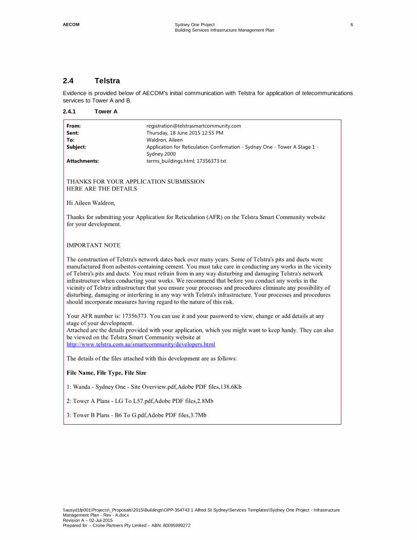
2.4 TelstraEvidence is provided below of AECOM’s initial communication with Telstra for application of telecommunicationsservices to Tower A and B.
2.4.1 Tower A

AECOM Sydney One ProjectBuilding Services Infrastructure Management Plan
\\ausyd1fp001\Projects\_Proposals\2015\Buildings\OPP-354743 1 Alfred St Sydney\Services Templates\Sydney One Project - InfrastructureManagement Plan - Rev - A.docxRevision A – 02-Jul-2015Prepared for – Crone Partners Pty Limited – ABN: 80095989272
7
2.4.2 Tower B

AECOM Sydney One ProjectBuilding Services Infrastructure Management Plan
\\ausyd1fp001\Projects\_Proposals\2015\Buildings\OPP-354743 1 Alfred St Sydney\Services Templates\Sydney One Project - InfrastructureManagement Plan - Rev - A.docxRevision A – 02-Jul-2015Prepared for – Crone Partners Pty Limited – ABN: 80095989272
8
3.0 Hydraulic Services
3.1 Sanitary Plumbing and Sewer Drainage3.1.1 Connection Point
Based on the Sydney Water Feasibility Letter 7th June 2010, the existing sewer drainage infrastructure does nothave sufficient capacity to cater for the proposed development. The advice letter indicates that a new connectionpoint will need to be provided from the existing manhole located in Albert St.
Figure 4.3: Sewer Drainage Connection Point
`
3.1.2 Basement Levels
A new site wide sewer drainage system shall extend from the new authority sewer connection point, completewith boundary trap and low/ high level vents. The site wide system will provide a gravity sewer drainage point forthe two towers.
Two new sewer pumping stations (one for each tower) will be provided on basement level 6, to collect alldischarges unable to gravitate to the connection point.
3.1.3 Tower A - Residential
All sanitary fixtures located within the residential tower will gravitate to the side wide system, via a fully ventedmodified sanitary drainage system.
Each commercial/ retail space will be provided with an Ø100mm sewer drainage turn- up (located at the back ofthe tenancy) for future extension by the tenant. The sewer drainage turn- up will gravitate to the side widedrainage system.
3.1.4 Tower B - Hotel
All sanitary fixtures located within the residential tower will gravitate to the side wide system, via a fully ventedmodified sanitary drainage system.
Each commercial/ retail space will be provided with an Ø100mm sewer drainage turn- up (located at the back ofthe tenancy) for future extension by the tenant. The sewer drainage turn- up will gravitate to the site wide drainagesystem.
Site
New connectionpoint to be providedfrom existingmanhole

AECOM Sydney One ProjectBuilding Services Infrastructure Management Plan
\\ausyd1fp001\Projects\_Proposals\2015\Buildings\OPP-354743 1 Alfred St Sydney\Services Templates\Sydney One Project - InfrastructureManagement Plan - Rev - A.docxRevision A – 02-Jul-2015Prepared for – Crone Partners Pty Limited – ABN: 80095989272
9
3.2 Stormwater Drainage3.2.1 Connection Point
Based on the Sydney Water Feasibility Letter 7th June 2010, the proposed development will not have to provideOn-Site Detention (OSD). The advice letter indicates that an existing Ø300 connection point to the “Tank Stream”may be utilised.
Figure 4.5: Stormwater Drainage Connection Point
3.2.2 Basement Levels
All surface water from the basement levels areas shall discharge directly to the “Tank Stream”, via the sub- soilpumping system
3.2.3 Tower A - Residential
Stormwater drainage from the residential tower shall be conveyed as follows:
· Roof areas shall be conveyed via conventional downpipes, to a common 20,000 litre above groundrainwater tank, complete with first flush device. The first flush device shall be capable of capturing thefirst 125 litres of run-off. The tank overflow shall be directed to Sydney Water’s “Tank Stream “system,as described in 3.2.1 Connection Point
· Surface water from balconies, terraces and driveways shall discharge directly from to Sydney Water’s“Tank Stream “system, via conventional downpipes.
3.2.4 Tower B - Hotel
As per residential tower.
Site
Existing “TankStream “connectionto be utilised

AECOM Sydney One ProjectBuilding Services Infrastructure Management Plan
\\ausyd1fp001\Projects\_Proposals\2015\Buildings\OPP-354743 1 Alfred St Sydney\Services Templates\Sydney One Project - InfrastructureManagement Plan - Rev - A.docxRevision A – 02-Jul-2015Prepared for – Crone Partners Pty Limited – ABN: 80095989272
10
3.3 Sub-soil Drainage3.3.1 Connection Point
All sub- soil drainage shall be conveyed to Sydney Water’s “Tank Stream “system, via the sub-soil pumpingsystem.
3.3.2 Basement Levels
Sub- soil drainage to the car parking levels shall consist of:
· Above ground car parking levels collected via elevated stormwater drainage pipework.
· Seepage water to be collected via slotted pipe located around the perimeter of the lowest basement carpark.
· Surface water collected via in-ground drainage pipe.
· All sub- soil drainage water shall be treated via a gross pollutant trap, prior to discharging to the pumpout pit.
3.3.3 Tower A - Residential
No sub-soil drainage is required to the residential tower.
3.3.4 Tower B - Hotel
No sub-soil drainage is required to the hotel tower.

AECOM Sydney One ProjectBuilding Services Infrastructure Management Plan
\\ausyd1fp001\Projects\_Proposals\2015\Buildings\OPP-354743 1 Alfred St Sydney\Services Templates\Sydney One Project - InfrastructureManagement Plan - Rev - A.docxRevision A – 02-Jul-2015Prepared for – Crone Partners Pty Limited – ABN: 80095989272
11
3.4 Potable Water Service3.4.1 Connection Point
Based on the Sydney Water Feasibility Letter 7th June 2010, the existing water infrastructure does not havesufficient capacity to cater for the proposed development. The advice letter indicates that a new connection pointwill need to be provided from the Ø450mm water main on the southern side of Albert St.
Figure 4.7: Potable Water Connection Point
3.4.2 Metering
Potable water metering shall be provided as follows:
· Main authorities’ residential meter
· Main authorities’ hotel meter
· Main authorities’ registered club
· Authorities’ meter for each commercial tenancy
· Individual apartment sub-meters
· Residential hot water plant inlet sub- meter
3.4.3 Basement Levels
A new unassisted (subject to fire flow pressure test) site wide potable supply (metered) shall extend from the newconnection point in Alfred St, complete with authorities water meter assembly and backflow prevention device.The site wide system will provide supply to the following areas:
· Tower A, Residential: domestic cold water storage tank, located on the roof top and intermediate plantroom. Water is to be pumped to the intermediate plant room and then cascade up to the roof top tankfrom the authorities’ water main, via a duplex transfer pumps.
· Tower B, Hotel- domestic cold water storage tank, located on the roof top plant room. Water is to betransferred to this tank from the authorities’ water main, via a duplex transfer pump.
· All water consuming fixtures and outlets located in the basement areas.
· Commercial/ retail areas
Site
New connectionfrom existingØ450mm water main

AECOM Sydney One ProjectBuilding Services Infrastructure Management Plan
\\ausyd1fp001\Projects\_Proposals\2015\Buildings\OPP-354743 1 Alfred St Sydney\Services Templates\Sydney One Project - InfrastructureManagement Plan - Rev - A.docxRevision A – 02-Jul-2015Prepared for – Crone Partners Pty Limited – ABN: 80095989272
12
3.4.4 Tower A - Residential
Potable water to each residential building shall be provided from the cold water storage tanks located on theintermediate and roof top plant rooms, via a triplex pressure booster pump set, and include:
· Individual apartment sub- meters located within the common corridors, in accordance with SydneyWater’s metering policy.
· Zone pressure reducing valves set to 350kPa, to limit fixture outlet pressures. Preliminary calculationsindicate that the sets will be required on levels 48, 37, 26 & 15.
· Apartments located below level 7 will require individual 350kPa pressure reducing valves, to limit fixtureoutlets pressures.
Each retail space will be provided with a capped Ø25mm potable water connection point for future extension bythe tenant. The potable water service will extend from the unassisted site wide supply, complete with anauthorities’ sub-meter
3.4.5 Tower B - Hotel
Potable water to the hotel shall be provided from a cold water storage tank located on the roof top plant rooms,via a triplex pressure booster pump set, and include:
· Zone pressure reducing valves set to 350kPa, to limit fixture outlet pressures. Preliminary calculationsindicate that the sets will be required on levels 19 & 11.
Each retail space will be provided with a capped Ø25mm potable water connection point for future extension bythe tenant. The potable water service will extend from the unassisted site wide supply, complete with anauthorities’ sub-meter.
3.5 Potable Hot Water Service3.5.1 Basement Levels
Each building shall be provided with potable hot water from a dedicated centralised gas fired system.
3.5.2 Metering
Potable hot water metering shall be provided as follows:
· Individual apartment sub-meters
· Individual sub- meters to common areas ( i.e. garbage rooms)
3.5.3 Basement Levels
No potable hot water shall be provided to the basement car park and podium.

AECOM Sydney One ProjectBuilding Services Infrastructure Management Plan
\\ausyd1fp001\Projects\_Proposals\2015\Buildings\OPP-354743 1 Alfred St Sydney\Services Templates\Sydney One Project - InfrastructureManagement Plan - Rev - A.docxRevision A – 02-Jul-2015Prepared for – Crone Partners Pty Limited – ABN: 80095989272
13
3.5.4 Tower A - Residential
Potable hot water to each residential apartment shall be provided from the dedicated centralised gas fired plant,via a flow and return loop, and include:
· Individual apartment sub- meters located within a cupboard, accessible via the common corridor
· Zone pressure reducing valves set to 350kPa, to limit fixture outlet pressures. Preliminary calculationsindicate that the sets will be required on levels 48, 37, 26 & 15.
· Apartments located below level 7 will require individual 350kPa pressure reducing valves, to limit fixtureoutlets pressures. Individual electric hot water units, and secondary circulation pumps to recirculate hotwater at the lower pressure zone
· Individual apartment thermostatic mixing valves to limit outlet temperatures to all fixtures to 50°C
3.5.5 Tower B - Hotel
Potable hot water to each hotel suite and sanitary outlets shall be provided from the dedicated centralised gasfired plant, via a flow and return loop, and include:
· Zone pressure reducing valves set to 350kPa, to limit fixture outlet pressures. Preliminary calculationsindicate that the sets will be required on levels 19 & 11.
Localised hot water units will be provided to the Hotel’s kitchen and back of house areas.
No potable hot water shall be provided to the retail areas.

AECOM Sydney One ProjectBuilding Services Infrastructure Management Plan
\\ausyd1fp001\Projects\_Proposals\2015\Buildings\OPP-354743 1 Alfred St Sydney\Services Templates\Sydney One Project - InfrastructureManagement Plan - Rev - A.docxRevision A – 02-Jul-2015Prepared for – Crone Partners Pty Limited – ABN: 80095989272
14
3.6 Gas ServicesPreliminary discussions obtained from Jemena indicate that the proposed development may be served from theexisting Ø110mm 1500kPa secondary supply main, located in Pitt St. The suitability of the connection point willneed to be confirmed with Jemena, via a formal application.
3.6.1 Basement Levels
A new site wide gas service shall extend from the authorities supply main in Pitt St, complete with authorities’ gasmetres. The site wide system will provide gas to the following areas:
· Each residential apartment
· Hot water units
· Hotel areas
· Registered Club
· Common areas.
· Retail areas
3.6.2 Metering
Authorities’ gas meters shall be provided, for the following:
· Centralised hot water plants
· Each residential apartment
· Hotel
· Registered Club
· Each commercial tenancy (2 off)
· Common areas (i.e. BBQ facilities)
Site
New connectionfrom existingØ110mm secondarymain

AECOM Sydney One ProjectBuilding Services Infrastructure Management Plan
\\ausyd1fp001\Projects\_Proposals\2015\Buildings\OPP-354743 1 Alfred St Sydney\Services Templates\Sydney One Project - InfrastructureManagement Plan - Rev - A.docxRevision A – 02-Jul-2015Prepared for – Crone Partners Pty Limited – ABN: 80095989272
15
3.6.3 Tower A - Residential
A gas supply, complete with authorities meter, located in the common corridor is to be provided to each apartmentto serve the following appliances:
· Gas cook top
A capped gas supply capable of providing 1000 mJ/hr is to be provided to each retail tenant, from the authorities’’gas meter. The tenant is to be responsible for extending the capped connection, as part of their fit-out works
3.6.4 Tower B - Hotel
A metered gas supply shall be provided to all gas consuming appliances located within the Hotel.
A metered gas supply shall be provided to all gas consuming appliances located within the Registered Club.
A capped gas supply capable of providing 1000 mJ/hr is to be provided to each retail tenant, from the authorities’’gas meter. The tenant is to be responsible for extending the capped connection, as part of their fit-out works


![IMP - MML IMP - MML IMP - MML IMP - MMLIMP - MML IMP - …imp.gob.pe/images/Planos de Zonif Abril 2019/2_San Juan de Lurigancho.pdf · zte-2 cv [2] cv av. leocio prado av. ferrocarril](https://img.pdfslide.us/doc/110x75/5e1a193af2030578f7455c4b/imp-mml-imp-mml-imp-mml-imp-mmlimp-mml-imp-impgobpeimagesplanos.jpg)