Embed Size (px)
Citation preview
S X R - S c r a t c h b u i l t t r a c k p l a n n i n g s y s t e m f o r U l t i m a t e R a c e r
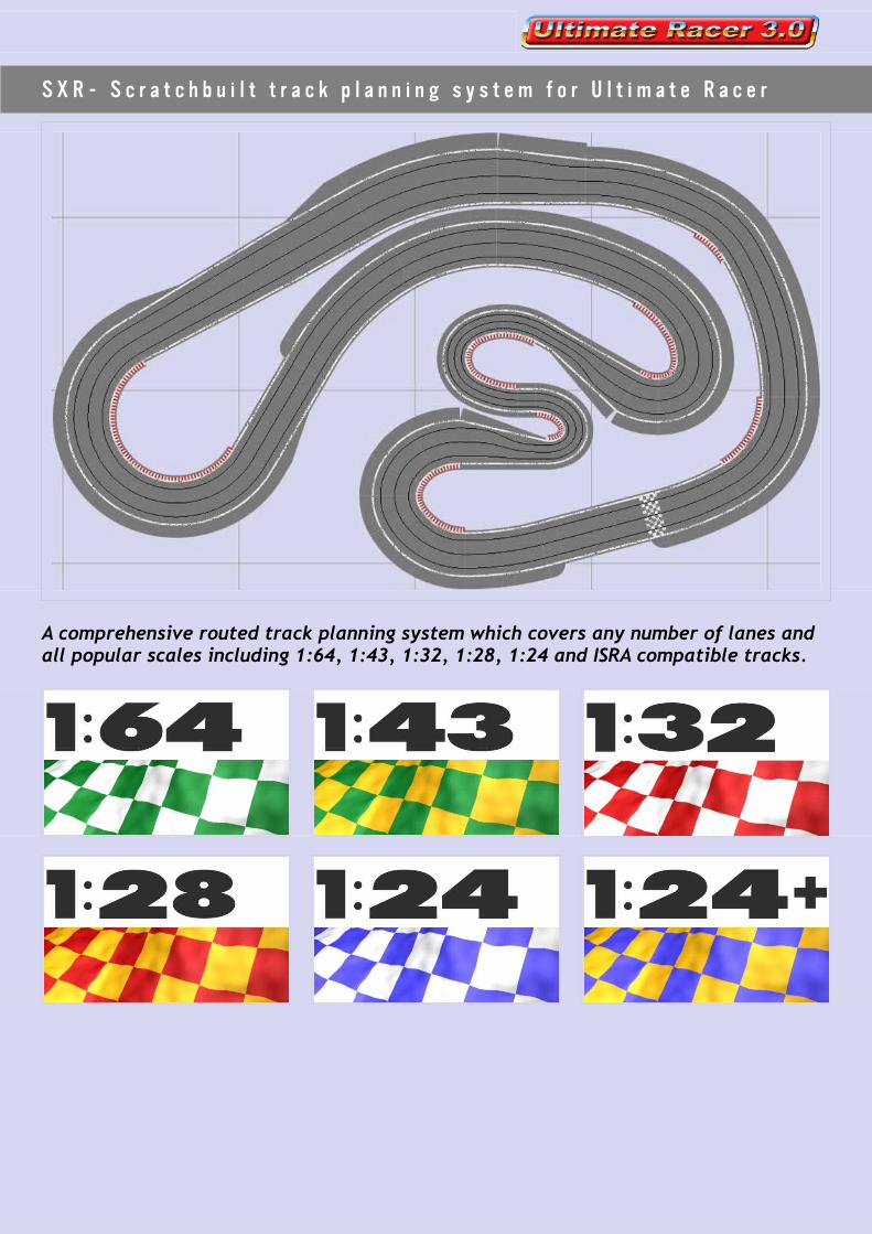
A comprehensive routed track planning system which covers any number of lanes and all popular scales including 1:64, 1:43, 1:32, 1:28, 1:24 and ISRA compatible tracks.

C o n t e n t s
Getting Started............................................................................4
Introduction.......................................................................4Advantages....................................................................4This Guide.....................................................................5
The Software......................................................................5Ultimate Racer...............................................................5
Have a play....................................................................5Links............................................................................5
Ultimate Racer................................................................5Slot Car Illustrated...........................................................5
Track Construction...............................................................6Construction Methods.......................................................6
Radius Arm....................................................................6Outside In......................................................................6Guide Strip....................................................................6CNC.............................................................................6
Links............................................................................6Chris Frost.....................................................................6Slot Car Illustrated...........................................................6Old Slot Racer.................................................................6
The System................................................................................7
Scales and Dimensions..........................................................7Lane Widths...................................................................7
Comparison Table.............................................................7Choosing a scale to use.....................................................7
Other Options.................................................................7Mixed Widths?.................................................................7Finding a balance.............................................................8
Track Reference System .......................................................8Overview......................................................................8
Lane number and width.....................................................9Straights.......................................................................9Curves..........................................................................9Lane Widths..................................................................10
Design Process...........................................................................11
Designing Your Track...........................................................11Before you Start............................................................11
Room Size....................................................................11Furniture & Obstructions..................................................11Driver viewpoints...........................................................11Marshalling...................................................................12Track Room Template.......................................................12Number of Lanes............................................................12
Using Track Pieces..........................................................13Tightest Curves..............................................................13Widest Corners..............................................................13
1

Compound Curves...........................................................13Tapers.........................................................................14Taper References............................................................14Digital Track Pieces.........................................................14
Using Borders................................................................14Types..........................................................................14References...................................................................14Applying Borders............................................................15Automatic....................................................................15Manual........................................................................15Working Example............................................................15
Editing Track Pieces........................................................16Back up.......................................................................16Example......................................................................17More...........................................................................17
When you've Designed your Track..........................................18Printing and Publishing....................................................18
Saving a picture of your design...........................................18Publishing to a website....................................................18Publishing to the Ultimate Racer Circuit Library......................19
Full Size...................................................................................19
Marking Out Your Track........................................................19Plans and Track Lists.......................................................19
Track Plans...................................................................20Track Names.................................................................20Colour Codes.................................................................20Track List.....................................................................21
Marking out - Example 1...................................................22Where to Start?.............................................................22The first steps...............................................................22
Marking out - Example 2...................................................25So How do we Start?........................................................25
Marking out - Example 3...................................................26Example 4 - CAD............................................................27
Conclusion................................................................................27Disclaimer....................................................................28Track Examples..............................................................28
Appendix.................................................................................29
Track Library Details...........................................................29SXR 1/64.....................................................................29SXR 1/43.....................................................................29SXR 1/32.....................................................................29SXR 1/28.....................................................................30SXR 1/24.....................................................................30SXR 1/24+....................................................................30
2
G e t t i n g S t a r t e d
I n t r o d u c t i o n
SXR is a comprehensive series of custom made track libraries for Ultimate Racer, allowing you to plan and build a massive range of scratch built, routed slot tracks, from single lane rally tracks up to eight lane commercial raceways, from 1:64 scale tracks up to ISRA compatible layouts.
The difference with the SXR track system is that it's not based on a particular track brand, it's specifically designed to help in the planning and layout of routed wooden, scratchbuilt tracks.
So you are not limited by the constraints of the track manufacturers, you're only limited by what you can imagine and what you can build. Virtually any track geometry you can imagine is available. Wide radius sweeping curves, corners that decrease or increase in radius, any number of lanes and any scale.
AdvantagesThe big advantage for track builders is that the SXR libraries are accurately defined, so that the track you build can be exactly how you planned it. It can fit exactly into the space you planned it to fit in, it can look exactly how you imagined it, and the designs you produce can be accurately laid out and built.
Compared to drawing out a plan on paper, using Ultimate Racer is much more flexible, allowing changes to be made quite easily during the design development phase.
Track designs can also be uploaded to a website or printed out extremely easily, for presentation, for sharing, and for discussion.
3
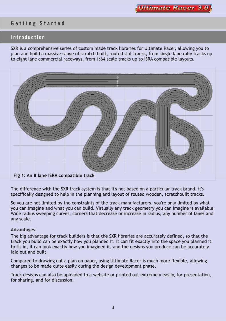
Fig 1: An 8 lane ISRA compatible track

This GuideAlthough this guide is not intended to tell you how to design or construct a track, or how to use Ultimate Racer, it will inevitably touch on these subjects. The SXR library and Ultimate Racer software are intended to be an integral part of that whole process of designing and building a slot track, so this guide is intended to integrate these elements into the process.
Some of you may be experienced track builders, others may be experienced users of Ultimate Racer. But on starting this project there were few people who were both. So we're attempting to produce a guide which will provide an overview as to how the software, the track libraries, the ruler and the router can all be brought together into one meaningful system.
So to start with we'll have a brief look at the software, then we'll have an equally brief look at track building and we'll provide links for extra exploration.
The rest of the guide will then deal in some detail, with the track libraries, the different scales, how to design your track, and how to layout your design in full size. It's certainly not rocket science, but a thorough understanding can help to reduce mistakes in the planning and building process.
T h e S o f t w a r e
Ultimate RacerThis guide assumes that you already have Ultimate Racer (UR Version 3.0.30r2 or higher) installed on your computer. If not, you can download it from the Ultimate Racer website http://www.uracerweb.org/
Have a playThe best way to get started is to open up the software and have a play. If you're not familiar with the UR track designer, you might find it easier to use a simple plastic track library to begin with. These libraries have a limited range of track pieces and are therefore easier to find your way around.
Once you are a little more familiar with the track editor, open up one of the SXR libraries and start designing.
Links
Ultimate RacerThe basic operations of the track layout editor are explained on the UR website.http://www.uracerweb.org/Presentation/TrackEditor.htm
Slot Car IllustratedThere is also a dedicated section on the Slot Car Illustrated forum if you have any questions or problems.http://www.slotcarillustrated.com/portal/forums/forumdisplay.php?f=71
4

Tr a c k C o n s t r u c t i o n
Construction MethodsAn in depth description of track construction methods is well beyond the remit of this guide. But since the building methods you use will affect how you design and how you layout your track, we should at least briefly mention some of the most popular methods.
In no particular order....
Radius ArmIn this method the curved slots are cut into the track using a router set on a radius arm which controls the radius of the curve being cut. This method obviously works well for constant radius corners but can get very complicated if you want decreasing or increasing radius corners.
Outside InThe method here is to cut out the outside shape of the track, clean and smooth it. Then a router jig or jigs, guided by the outside edge are used to cut the slots. Obviously this method requires the outside edge to be a constant distance from the slots, so it is perhaps not ideal for scenic tracks where you might want space for buildings or landscaping etc.
Guide StripWith this method a flexible strip is pinned to the track surface, to act as a guide for the router. This allows complex, compound curves and doesn't require a constant outside edge, but does mean you will have a lot of small pin holes to fill.
CNCThere are lots of companies that have computer controlled routers and they can take your design and supply you with a routed board or boards, ready for painting and braiding. However it obviously costs a lot more than routing it yourself.
Links
Chris FrostA fantastic resource for anybody building a track. The emphasis is on large club tracks, but much of the information would be useful to all.
http://www.bscra.byethost16.com/trackbuild/index.htm
Slot Car IllustratedThis brilliant online forum has a section dedicated to routed tracks
http://slotcarillustrated.com/portal/forums/forumdisplay.php?f=28
Old Slot RacerLoads of track examples and some information on the guide strip method.
http://oldslotracer.com/
5

T h e S y s t e m
S c a l e s a n d D i m e n s i o n s
Lane WidthsThe SXR system provides a range of lane widths suitable for slot cars of most popular scales. Of course the idea of a scaled track size is quite meaningless as real tracks do not have a standard width and certainly don't have lanes as such.
So the idea of naming the scales is simply to provide an indication of the slot cars which might be most suitable for each lane width. It also hopefully gives an easily understood point of reference for each library, by using lane widths which are comparable to popular plastic track systems.
The table below gives an outline of the various SXR libraries, their lane widths, their approximate scales, and the closest comparable plastic track. More details are available in the appendix dealing with each library, at the end of this guide.
Comparison Table
Choosing a scale to useWhich scale to use?
The simple answer is that it depends on the scale of your cars. If you are are racing 1:32 scale cars you should probably use the SXR 1/32 system, which is 8cm in width per lane, just 2mm per lane wider than Scalextric track. If you race 1:43 scale cars, use the SXR 1/43 system etc.
Other OptionsHowever there are other options. If you're racing 1/32 Le Mans or Can Am type cars, or any other wide car, or if you race without magnets, you might prefer to use the SXR 1/28 system, which compares to the Ninco track system and gives a bit of extra room for sliding. Or if you've got the space you might want to go for for the SXR 1/24 system, which compares to the Carrera track system and would give you even more room for manouevre at 1/32 scale, but would also allow you to race 1/24 scale cars.
Mixed Widths?You can also use mixed lane widths on the same track, by using more than one track library. This can provide squeezed, or expanded sections as shown in the track below.
6
Name Comparable to
SXR 1/64 Tyco, Tomy 4 1.57SXR 1/43 Carrera Go, SCX Compact 6 2.36SXR 1/32 Scalextric 8 3.15SXR 1/28 Ninco 9 3.54SXR 1/24 Carrera 10 3.94SXR 1/24+ Championship Raceway 11 4.33
Lane Width in cm
Lane Width in inches
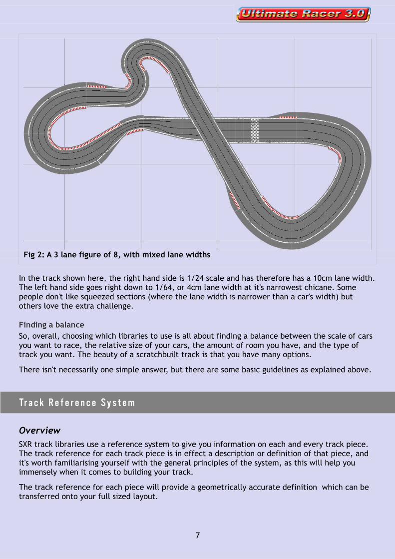
In the track shown here, the right hand side is 1/24 scale and has therefore has a 10cm lane width. The left hand side goes right down to 1/64, or 4cm lane width at it's narrowest chicane. Some people don't like squeezed sections (where the lane width is narrower than a car's width) but others love the extra challenge.
Finding a balanceSo, overall, choosing which libraries to use is all about finding a balance between the scale of cars you want to race, the relative size of your cars, the amount of room you have, and the type of track you want. The beauty of a scratchbuilt track is that you have many options.
There isn't necessarily one simple answer, but there are some basic guidelines as explained above.
Tr a c k R e f e r e n c e S y s t e m
OverviewSXR track libraries use a reference system to give you information on each and every track piece. The track reference for each track piece is in effect a description or definition of that piece, and it's worth familiarising yourself with the general principles of the system, as this will help you immensely when it comes to building your track.
The track reference for each piece will provide a geometrically accurate definition which can be transferred onto your full sized layout.
7
Fig 2: A 3 lane figure of 8, with mixed lane widths
You can display the reference for each piece in your design by going to View > Preferences, then clicking on the Display section reference tick box.
Lane number and widthThe first two numbers of the main track references are simply telling us how many lanes the track has and the distance in cm between each lane. Remember, each scale has a different lane width, as we saw in the table shown earlier, and in the appendix at the end of this guide.
So, a track section with a reference beginning 2-8, is a 2 lane track with a distance of 8cm between lanes (nominally 1/32 scale). A track section with a reference that starts 8-9 is an eight lane piece with a distance of 9cm between lanes (1/28).
These two numbers at the beginning of each reference also gives us the total track width, i.e. a track piece that begins 6-10 is 6x10cm, or 60cm wide.
After the first two numbers the references then divide up into straights and curves.
StraightsThe straights are signified by the letter S and a number representing the length of the straight, so S100 is a 100cm long straight, S25 is a 25cm long straight.
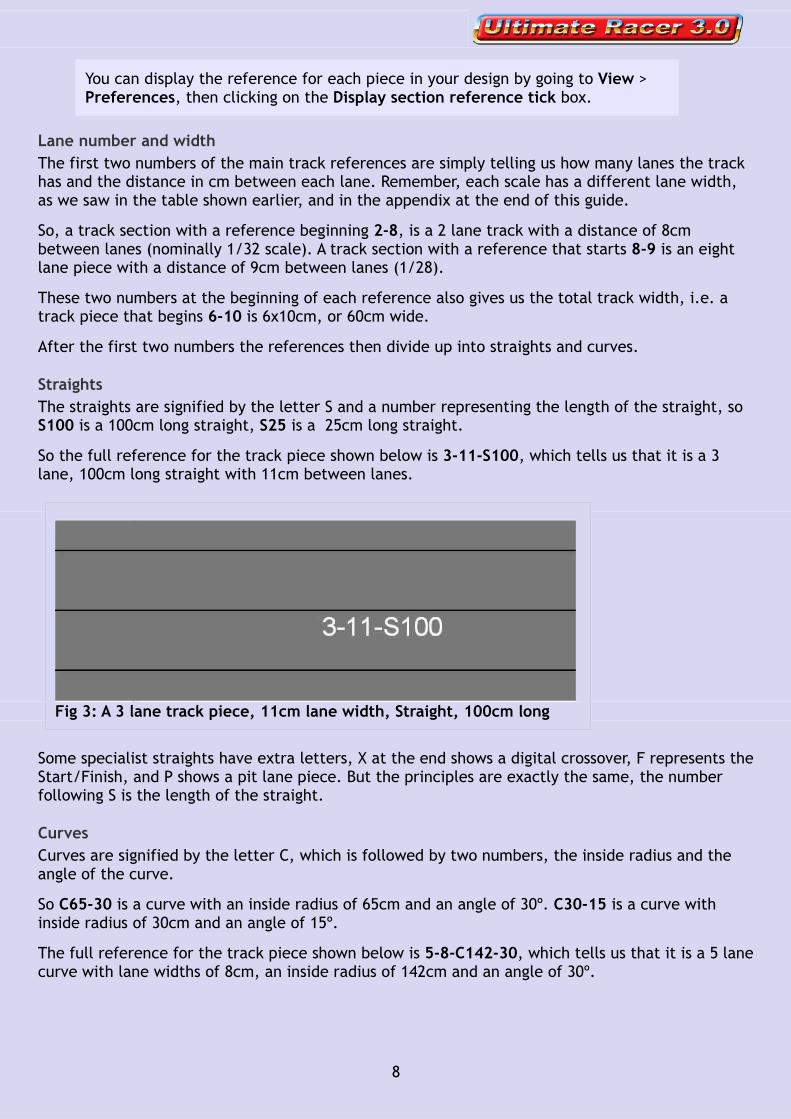
So the full reference for the track piece shown below is 3-11-S100, which tells us that it is a 3 lane, 100cm long straight with 11cm between lanes.
Some specialist straights have extra letters, X at the end shows a digital crossover, F represents the Start/Finish, and P shows a pit lane piece. But the principles are exactly the same, the number following S is the length of the straight.
CurvesCurves are signified by the letter C, which is followed by two numbers, the inside radius and the angle of the curve.
So C65-30 is a curve with an inside radius of 65cm and an angle of 30º. C30-15 is a curve with inside radius of 30cm and an angle of 15º.
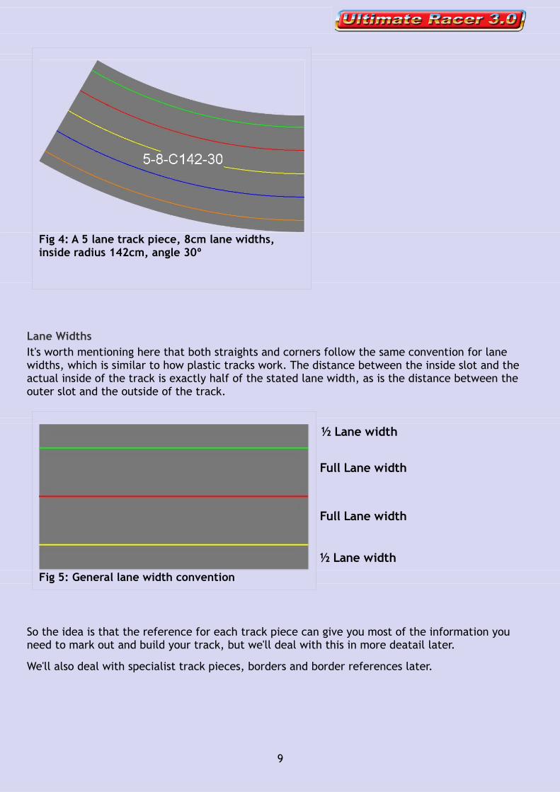
The full reference for the track piece shown below is 5-8-C142-30, which tells us that it is a 5 lane curve with lane widths of 8cm, an inside radius of 142cm and an angle of 30º.
8
Fig 3: A 3 lane track piece, 11cm lane width, Straight, 100cm long
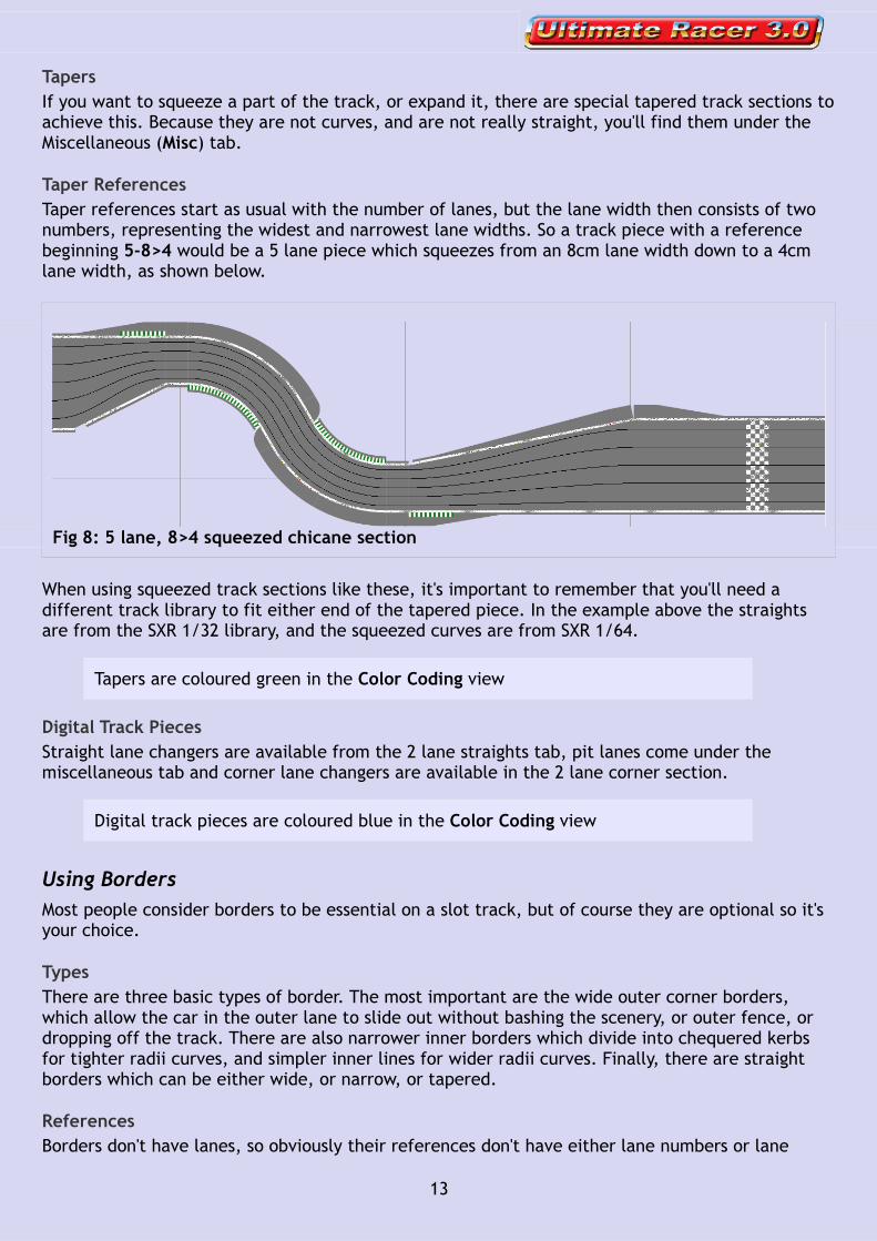
Lane WidthsIt's worth mentioning here that both straights and corners follow the same convention for lane widths, which is similar to how plastic tracks work. The distance between the inside slot and the actual inside of the track is exactly half of the stated lane width, as is the distance between the outer slot and the outside of the track.
So the idea is that the reference for each track piece can give you most of the information you need to mark out and build your track, but we'll deal with this in more deatail later.
We'll also deal with specialist track pieces, borders and border references later.
9
½ Lane width
Full Lane width
Fig 4: A 5 lane track piece, 8cm lane widths, inside radius 142cm, angle 30º
Full Lane width
½ Lane widthFig 5: General lane width convention

D e s i g n P r o c e s s
D e s i g n i n g Yo u r Tr a c k
Before you StartBefore you start designing a track there are a few things which are worth considering, and it's sometimes worth setting up a few things in UR before you start. Once you've got the basics set up, you can save them as a template to use as the basis to start any new track designs.
Room SizeThe most obvious thing to consider is probably the size of the room where the track will be situated, or the space you want the track to occupy. Measure the space as accurately as you can and set up a room in the track designer. There are various Room shapes available from the Room Toolbar. Click to insert the most appropriate.
If the Room Toolbar is not visible go to View > Toolbars and click on Room
The important thing here is to be as accurate as possible, both in the measurement of the room size and the setting up of the shape that represents it.
To do this you'll need to set the grid size to cm (centimetres) or even in (inches) if you prefer. Don't use metres or feet unless the measurements are not too critical.
To set the units of measurement go to View click Preferences click on the Grid rotation settings tab and set the Major Grid units to cm or in
Now zoom in in on the various parts of your room and drag the corners until the room shape is accurately set up. You'll see there are measurements to help here.
Furniture & ObstructionsSo you've set up the basic room shape, but there are bound to be various objects you'll need to avoid as well. Furniture like cupboards, shelves or sofas. Doorways and access etc.
Use the Shapes toolbar to put these onto your plan.
If the Shapes Toolbar is not visible go to View > Toolbars and click on Shapes
To set the dimensions of a Shape accurately, after inserting it, right click on the Shape, click Properties and type in the Width and Depth.
Driver viewpointsIt's obviously important that all drivers can see the whole of the track, or at least the vital corners and braking points. L shapes and U shapes are very tempting as they can often be a way to include more track in a limited space. But they also require very careful consideration of the drivers position to avoid drivers blocking each others view.
10

You can use the ellipse Shape tool to mark driver positions.
MarshallingIf you're designing a commercial or competition track, marshalling becomes a very important issue. Think about where the marshals will stand to avoid blocking sight lines and also think how far they can reach.
You can use the ellipse Shape tool to mark marshalling stations.
Even if you're designing a home track, it's important to consider how you will pick up a de-slotted car. If the track is too deep you won't be able to reach over easily.
Track Room TemplateSo at the end of this process you should have a track room template you can use as the starting point for your designs. To simplify matters during the design process you might just use the track table shape, once that is established.
Number of LanesBefore you start designing you'll also need to decide on the number of lanes your track will have, and the scale you want, so you can choose the appropriate SXR track library. Obviously you might want to try out various options and alternative designs, or you might change your mind later, but for now you need to choose at least the scale, and load the appropriate library.
11
Fig 6: Track Room Template Example

Using Track PiecesYou should, by now, be quite familiar with Ultimate Racer, so it should be reasonably obvious how to use the track pieces. There are however, many more track pieces to consider in each SXR library, when compared to a standard plastic track library. You'll probably need to scroll through the library to find all of the pieces, or you might find it useful to enlarge your library toolbar.
Tightest CurvesIt's worth having a think about the tightest radius of corner that you find acceptable. For instance, some people feel that the inside lane of a Scalextric R1 is too tight, and in the SXR 1/32 library the C6 corners roughly equate to a Scaley R1, with an inside radius of 6cm.
For large commercial or public tracks, you might consider an even wider curve as the minimum. It's worth having a think and making a note of which track pieces you might want to avoid.
More comparisons of curve radii are available in the Appendix at the end of this guide.
Widest CornersSimilarly, you should also consider the widest curve you can practically build, particularly if you plan to use a router with a radius arm to cut your slots. With this method, the widest radius corner will be limited by the size of your radius arm.
Ultra wide curves with an inside radius of 2m or more are coloured red in the Color Coding view
Compound CurvesCompound or parabolic curves are easily created by using decreasing or increasing radius corners as you go along, as shown below.
However, if you're using a radius arm to cut your slots, compound curves like these can be difficult to cut.
12
Fig 7: Increasing and decreasing radius curves
TapersIf you want to squeeze a part of the track, or expand it, there are special tapered track sections to achieve this. Because they are not curves, and are not really straight, you'll find them under the Miscellaneous (Misc) tab.
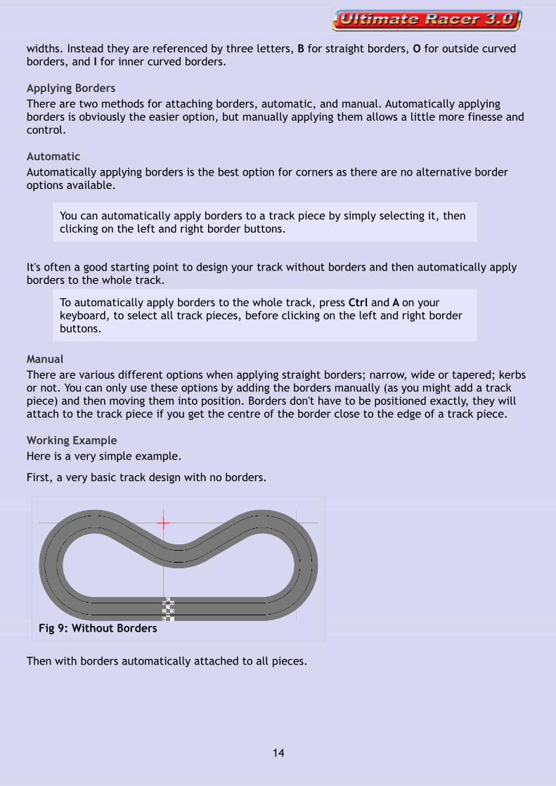
Taper ReferencesTaper references start as usual with the number of lanes, but the lane width then consists of two numbers, representing the widest and narrowest lane widths. So a track piece with a reference beginning 5-8>4 would be a 5 lane piece which squeezes from an 8cm lane width down to a 4cm lane width, as shown below.
When using squeezed track sections like these, it's important to remember that you'll need a different track library to fit either end of the tapered piece. In the example above the straights are from the SXR 1/32 library, and the squeezed curves are from SXR 1/64.
Tapers are coloured green in the Color Coding view
Digital Track PiecesStraight lane changers are available from the 2 lane straights tab, pit lanes come under the miscellaneous tab and corner lane changers are available in the 2 lane corner section.
Digital track pieces are coloured blue in the Color Coding view
Using BordersMost people consider borders to be essential on a slot track, but of course they are optional so it's your choice.
TypesThere are three basic types of border. The most important are the wide outer corner borders, which allow the car in the outer lane to slide out without bashing the scenery, or outer fence, or dropping off the track. There are also narrower inner borders which divide into chequered kerbs for tighter radii curves, and simpler inner lines for wider radii curves. Finally, there are straight borders which can be either wide, or narrow, or tapered.
ReferencesBorders don't have lanes, so obviously their references don't have either lane numbers or lane
13
Fig 8: 5 lane, 8>4 squeezed chicane section
widths. Instead they are referenced by three letters, B for straight borders, O for outside curved borders, and I for inner curved borders.
Applying BordersThere are two methods for attaching borders, automatic, and manual. Automatically applying borders is obviously the easier option, but manually applying them allows a little more finesse and control.
AutomaticAutomatically applying borders is the best option for corners as there are no alternative border options available.
You can automatically apply borders to a track piece by simply selecting it, then clicking on the left and right border buttons.
It's often a good starting point to design your track without borders and then automatically apply borders to the whole track.
To automatically apply borders to the whole track, press Ctrl and A on your keyboard, to select all track pieces, before clicking on the left and right border buttons.
ManualThere are various different options when applying straight borders; narrow, wide or tapered; kerbs or not. You can only use these options by adding the borders manually (as you might add a track piece) and then moving them into position. Borders don't have to be positioned exactly, they will attach to the track piece if you get the centre of the border close to the edge of a track piece.
Working ExampleHere is a very simple example.
First, a very basic track design with no borders.
Then with borders automatically attached to all pieces.
14
Fig 9: Without Borders
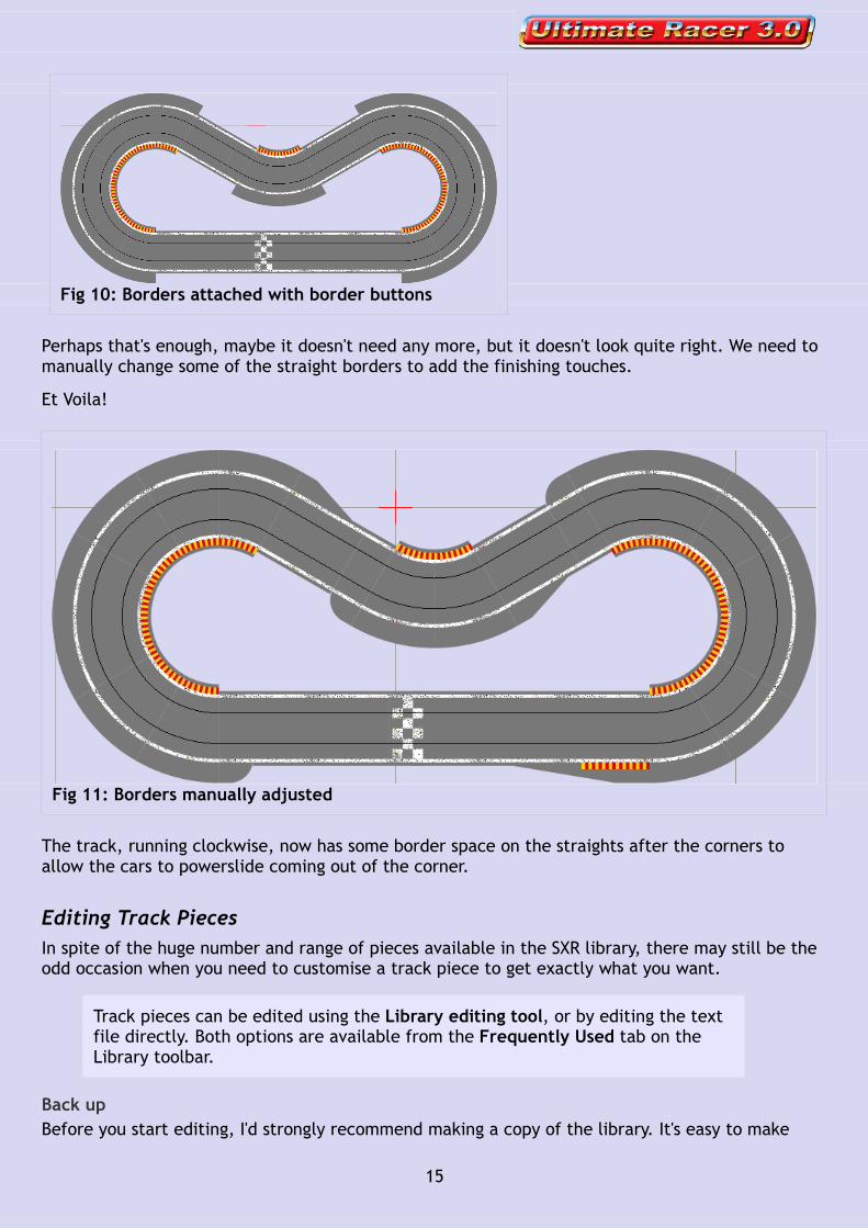
Perhaps that's enough, maybe it doesn't need any more, but it doesn't look quite right. We need to manually change some of the straight borders to add the finishing touches.
Et Voila!
The track, running clockwise, now has some border space on the straights after the corners to allow the cars to powerslide coming out of the corner.
Editing Track PiecesIn spite of the huge number and range of pieces available in the SXR library, there may still be the odd occasion when you need to customise a track piece to get exactly what you want.
Track pieces can be edited using the Library editing tool, or by editing the text file directly. Both options are available from the Frequently Used tab on the Library toolbar.
Back upBefore you start editing, I'd strongly recommend making a copy of the library. It's easy to make
15
Fig 10: Borders attached with border buttons
Fig 11: Borders manually adjusted

mistakes, so it's important to have a backup.
Ultimate Racer's track library files can be found in the location > Program Files > Racer30 > Library.
Track library files are simple text files (.txt) and if you are familiar with the reference system and geometry of the SXR libraries, then it shouldn't be too difficult to pick out the elements you want to edit. The main problem is finding the piece you want amongst hundreds of other pieces.
ExampleSo let's start by looking at a simple straight track piece, reference 2-10-S30. It's a 2 lane 30cm long straight with a lane width of 10cm. In the library text file (SXR124.txt) it looks like this....
[2-10-S30]Name=S30Notes=Shape=20,30Equivalent=OneWay=Frequent=yesColorCoding=7895160Texture1=f,120,120,120Lane1=5,5Lane2=15,15
In the Library editing tool the same information is presented graphically.
The track reference is in square brackets [2-10-S30], each piece must have a unique reference. The name, which follows is simply a shortened version of the reference, S30. The Shape defines the piece as 20cm wide and 30cm long, and at the end the Lanes define the position of each lane.
Whichever method you choose to edit the track piece, it's important to pick a track piece which is close to what you want and duplicate, or copy it. So, if you specifically needed a 2 lane, 37cm long straight, we could start off with the 2 lane 30cm straight shown above.
In the Library editing tool we would select the piece and click Duplicate. If we were editing the text file we'd select the section shown and copy/paste it. This avoids overwriting the original piece and losing it.
To change the length of the new track piece from 30cm to 37cm we can simply change Shape=20,30 to Shape=20,37. We would then change the reference to 2-10-S37 and the name to S37.
MoreThere is more information about editing track pieces in the Ultimate Racer Help section and online...
http://www.uracer.org/Help/editor/editor_library_editor.htm
16
W h e n y o u ' v e D e s i g n e d y o u r Tr a c k
Printing and PublishingUltimate Racer has a wide range of options for sharing your track design, and this can be extremely useful for a number of reasons.
• If you are designing a club track you will obviously have clients or fellow racers you need to show your designs to, for discussion and eventually, final approval.
• If you are designing a track for a private client, again you will want to show them your designs.
• Even if you are designing a track simply for your own home use, you might want to share it with friends, fellow racers, or the wider slot community. You might want some advice on your layout from those with more experience, or you might just want to show off your masterpiece.
It's all good, and sharing your designs is part of the fun.
Saving a picture of your design
To save a picture of your track design go to File > Save As, then change the Save as type to JPEG, or Bitmap from the dropdown list
The image will be saved exactly as it looks on the screen, so make sure you've made it look as nice as possible and set the zoom as high as possible to get a high resolution image.
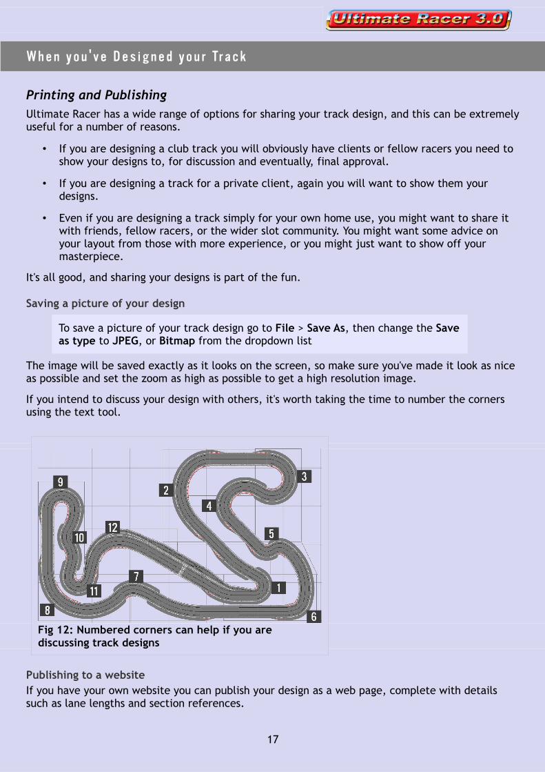
If you intend to discuss your design with others, it's worth taking the time to number the corners using the text tool.
Publishing to a websiteIf you have your own website you can publish your design as a web page, complete with details such as lane lengths and section references.
17
Fig 12: Numbered corners can help if you are discussing track designs

To publish a design to your own site, go to > File > Publish on the web. The first time you use the web publisher you'll need to enter your site's details. Thereafter you can simply select your design from the list and click Transfer
You can preview the web page at any time before uploading
To preview your design's web page go to Circuit > Properties then click Print. This will open a new window in your internet browser.
If you don't have your own website, you can of course upload your image to any photo hosting site such as Photobucket, Flikr etc
Publishing to the Ultimate Racer Circuit LibraryYou can also publish your design directly to UR's circuit library.
http://www.uracerweb.org/Layouts/TrackList.html
To publish your track on the Ultimate Racer site, go to File > UR30 WWW. The first time you use this feature you'll need to enter your details and request a password, which will be returned by email. Thereafter you can simply select your track and click Submit.
F u l l S i z e
M a r k i n g O u t Yo u r Tr a c k
Once the track design is finalised, approved and ready to go, the next stage is to mark it out and make it.
Plans and Track ListsBefore you start marking out your full size track in the workshop, you'll need to get together all the various plans and lists you'll need. Obviously you'll need to print these off unless you plan to take the computer into the workshop.
We'll use a very basic track design to illustrate how we transfer the plan to a full size track.
18
Fig 13: The basic track plan
Here we've set up the track onto a sheet of MDF which is available in several sizes in the SXR MDF library. Here we've used a standard sheet size of 244cm x 122cm, or 8' x 4'.
Track PlansFirstly you'll need the basic track plan (as shown above), but in truth this is more for a general idea than for the specific details. By now I'm sure you'll already have a picture of the basic plan so get that printed off.
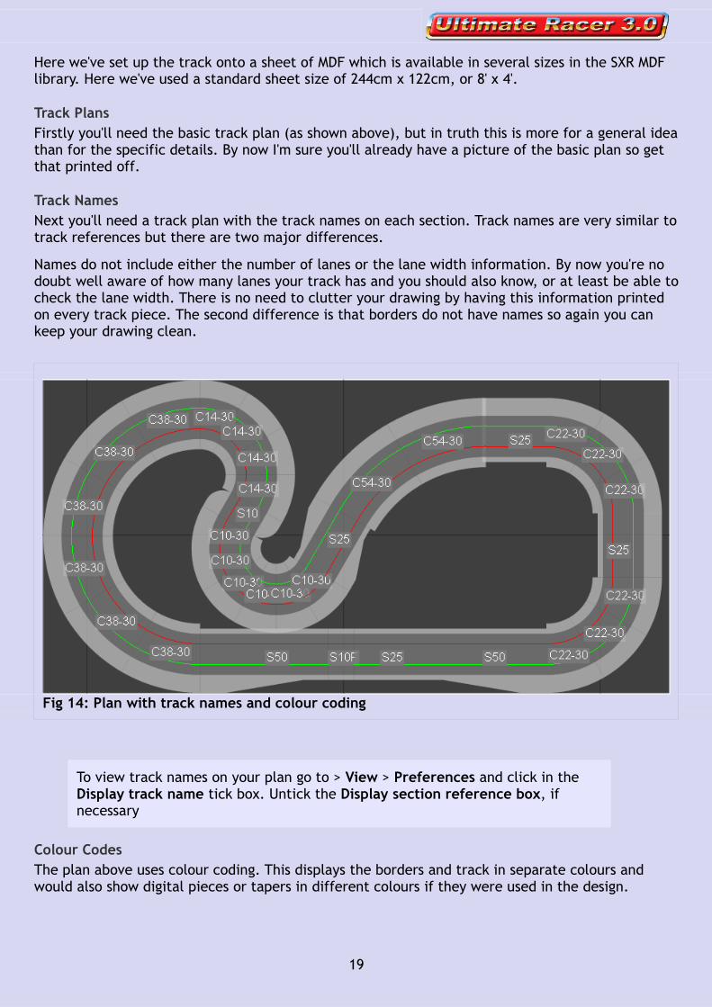
Track NamesNext you'll need a track plan with the track names on each section. Track names are very similar to track references but there are two major differences.
Names do not include either the number of lanes or the lane width information. By now you're no doubt well aware of how many lanes your track has and you should also know, or at least be able to check the lane width. There is no need to clutter your drawing by having this information printed on every track piece. The second difference is that borders do not have names so again you can keep your drawing clean.
To view track names on your plan go to > View > Preferences and click in the Display track name tick box. Untick the Display section reference box, if necessary
Colour CodesThe plan above uses colour coding. This displays the borders and track in separate colours and would also show digital pieces or tapers in different colours if they were used in the design.
19
Fig 14: Plan with track names and colour coding
To show colour coding on your plan click the Color Coding button on the Display Toolbar.
The colour coded view also shows up a slight overlap towards the top right of the track where the C54-30 overlaps the S25. We'll deal with that when we get to that point in the marking out process.
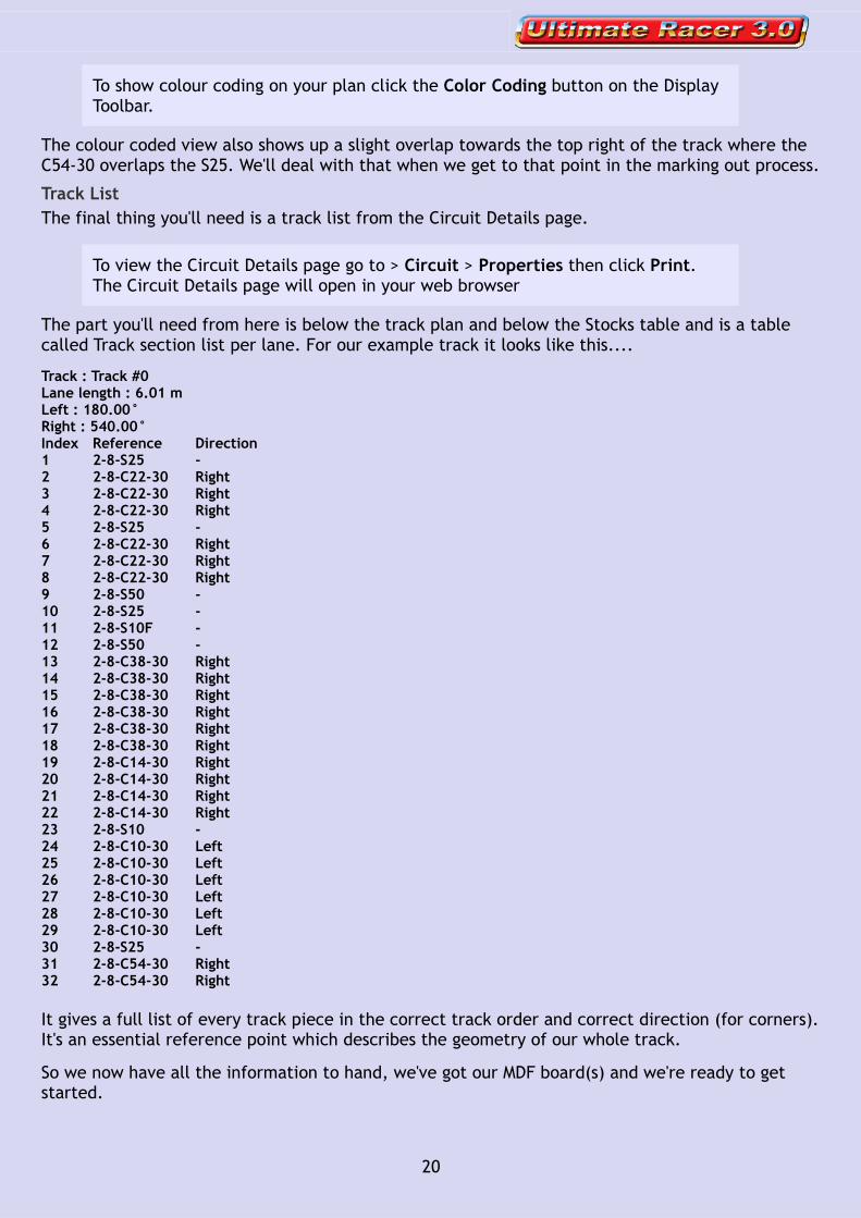
Track ListThe final thing you'll need is a track list from the Circuit Details page.
To view the Circuit Details page go to > Circuit > Properties then click Print. The Circuit Details page will open in your web browser
The part you'll need from here is below the track plan and below the Stocks table and is a table called Track section list per lane. For our example track it looks like this....
Track : Track #0Lane length : 6.01 m Left : 180.00° Right : 540.00° Index Reference Direction1 2-8-S25 - 2 2-8-C22-30 Right 3 2-8-C22-30 Right 4 2-8-C22-30 Right 5 2-8-S25 - 6 2-8-C22-30 Right 7 2-8-C22-30 Right 8 2-8-C22-30 Right 9 2-8-S50 - 10 2-8-S25 - 11 2-8-S10F - 12 2-8-S50 - 13 2-8-C38-30 Right 14 2-8-C38-30 Right 15 2-8-C38-30 Right 16 2-8-C38-30 Right 17 2-8-C38-30 Right 18 2-8-C38-30 Right 19 2-8-C14-30 Right 20 2-8-C14-30 Right 21 2-8-C14-30 Right 22 2-8-C14-30 Right 23 2-8-S10 - 24 2-8-C10-30 Left 25 2-8-C10-30 Left 26 2-8-C10-30 Left 27 2-8-C10-30 Left 28 2-8-C10-30 Left 29 2-8-C10-30 Left 30 2-8-S25 - 31 2-8-C54-30 Right 32 2-8-C54-30 Right
It gives a full list of every track piece in the correct track order and correct direction (for corners). It's an essential reference point which describes the geometry of our whole track.
So we now have all the information to hand, we've got our MDF board(s) and we're ready to get started.
20
Marking out - Example 1This method is ideal for the radius arm method of construction
Where to Start?There are no set rules on where is best to start the marking out process. It's a matter of judgement and to some degree will depend on your track design and your method of construction.
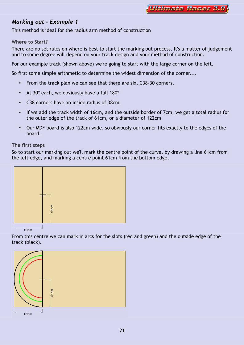
For our example track (shown above) we're going to start with the large corner on the left.
So first some simple arithmetic to determine the widest dimension of the corner....
• From the track plan we can see that there are six, C38-30 corners.
• At 30º each, we obviously have a full 180º
• C38 corners have an inside radius of 38cm
• If we add the track width of 16cm, and the outside border of 7cm, we get a total radius for the outer edge of the track of 61cm, or a diameter of 122cm
• Our MDF board is also 122cm wide, so obviously our corner fits exactly to the edges of the board.
The first stepsSo to start our marking out we'll mark the centre point of the curve, by drawing a line 61cm from the left edge, and marking a centre point 61cm from the bottom edge,
From this centre we can mark in arcs for the slots (red and green) and the outside edge of the track (black).
21
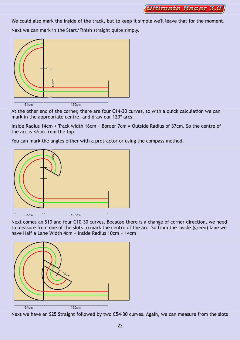
We could also mark the inside of the track, but to keep it simple we'll leave that for the moment.
Next we can mark in the Start/Finish straight quite simply.
At the other end of the corner, there are four C14-30 curves, so with a quick calculation we can mark in the appropriate centre, and draw our 120º arcs.
Inside Radius 14cm + Track width 16cm + Border 7cm = Outside Radius of 37cm. So the centre of the arc is 37cm from the top
You can mark the angles either with a protractor or using the compass method.
Next comes an S10 and four C10-30 curves. Because there is a change of corner direction, we need to measure from one of the slots to mark the centre of the arc. So from the inside (green) lane we have Half a Lane Width 4cm + Inside Radius 10cm = 14cm
Next we have an S25 Straight followed by two C54-30 curves. Again, we can measure from the slots
22
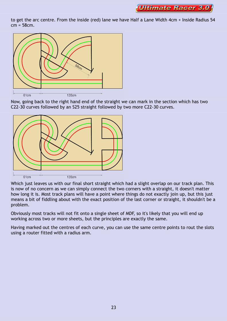
to get the arc centre. From the inside (red) lane we have Half a Lane Width 4cm + Inside Radius 54 cm = 58cm.
Now, going back to the right hand end of the straight we can mark in the section which has two C22-30 curves followed by an S25 straight followed by two more C22-30 curves.
Which just leaves us with our final short straight which had a slight overlap on our track plan. This is now of no concern as we can simply connect the two corners with a straight, it doesn't matter how long it is. Most track plans will have a point where things do not exactly join up, but this just means a bit of fiddling about with the exact position of the last corner or straight, it shouldn't be a problem.
Obviously most tracks will not fit onto a single sheet of MDF, so it's likely that you will end up working across two or more sheets, but the principles are exactly the same.
Having marked out the centres of each curve, you can use the same centre points to rout the slots using a router fitted with a radius arm.
23
Marking out - Example 2This example is ideal for making larger commercial or club tracks, either by the radius arm method or the outside in method.
As in Example 1 you'll need all the track plans and track lists mentioned at the start of this section, but assuming you are building a multilane track, there is no way you will be able to fit any substantial part of the track onto a single sheet of MDF. So it makes sense to divide up the track into sections which will fit onto a single sheet, a modular approach if you like. As well as making the track easier to build it also makes it easier to transport.
All of the techniques mentioned in Example 1 are still valid, but there is one more vital step before we get started.
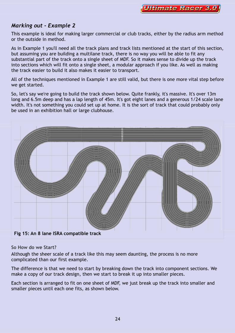
So, let's say we're going to build the track shown below. Quite frankly, it's massive. It's over 13m long and 6.5m deep and has a lap length of 45m. It's got eight lanes and a generous 1/24 scale lane width. It's not something you could set up at home. It is the sort of track that could probably only be used in an exhibition hall or large clubhouse.
So How do we Start?Although the sheer scale of a track like this may seem daunting, the process is no more complicated than our first example.
The difference is that we need to start by breaking down the track into component sections. We make a copy of our track design, then we start to break it up into smaller pieces.
Each section is arranged to fit on one sheet of MDF, we just break up the track into smaller and smaller pieces until each one fits, as shown below.
24
Fig 15: An 8 lane ISRA compatible track

Obviously it is quite some task to build so many pieces, organise all of them, label them, keep track of them, transport them and assemble them. Actually, it's a massive undertaking
But for our purpose here, in terms of explaining the marking out, it's actually much simpler. There is really only one radius and one angle on each sheet, so there is very little to add to the techniques explained in example 1.
Marking out - Example 3This example is only really suitable for the guide strip method of track construction and would certainly not work for any method where strict accuracy is required. There is more art to this than science, but it can work very well with the guide strip construction method.
We could call it laying out by eye. In other words we simply draw the track plan onto the board. If we don't like what we see, we rub it out and do it again.
We can use the wire render and grid settings to help give us a framework, as shown below. The grid shown on our screen can be easily marked out onto the board itself. Where the slots or the edge of the track intersect a grid line on the plan, we can also mark the board accordingly. Once all the intersections are marked we can then join up all the marks freehand to give us the track layout.
25
Fig 16: Sectional arrangement onto MDF sheets
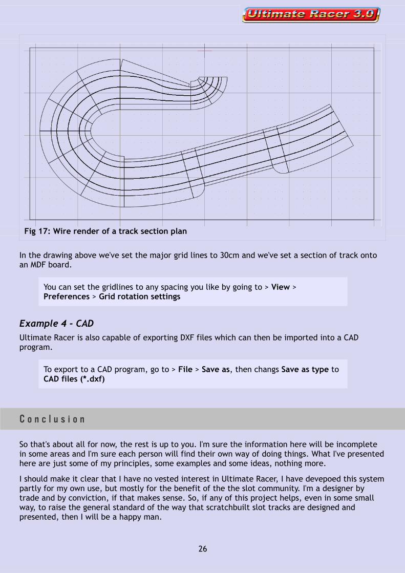
In the drawing above we've set the major grid lines to 30cm and we've set a section of track onto an MDF board.
You can set the gridlines to any spacing you like by going to > View > Preferences > Grid rotation settings
Example 4 - CADUltimate Racer is also capable of exporting DXF files which can then be imported into a CAD program.
To export to a CAD program, go to > File > Save as, then changs Save as type to CAD files (*.dxf)
C o n c l u s i o n
So that's about all for now, the rest is up to you. I'm sure the information here will be incomplete in some areas and I'm sure each person will find their own way of doing things. What I've presented here are just some of my principles, some examples and some ideas, nothing more.
I should make it clear that I have no vested interest in Ultimate Racer, I have devepoed this system partly for my own use, but mostly for the benefit of the the slot community. I'm a designer by trade and by conviction, if that makes sense. So, if any of this project helps, even in some small way, to raise the general standard of the way that scratchbuilt slot tracks are designed and presented, then I will be a happy man.
26
Fig 17: Wire render of a track section plan
DisclaimerPlease bear in mind that I have not had a chance to use every track piece in my own design work, let alone in an actual track build, so I can't claim that every track piece has been thoroughly tested. There are many hundreds of track pieces, so I'm sure a few will be less than perfect. Please use your common sense and make sure to check and double check your designs at the marking out stage. Measure twice and cut once is an old saying with much wisdom.
If you have any questions, or if you find any errors, either here in the guide, or in the libraries themselves, please let me know on the forum.http://www.slotcarillustrated.com/portal/forums/forumdisplay.php?f=71
Please also let me know if you have any requests or suggestions for advancing the system. These libraries have already taken various opinions and ideas into account during development, but I always welcome anybody's thoughts and experience.
Thank You
Jason Brown
http://www.phantomdrum.co.uk/
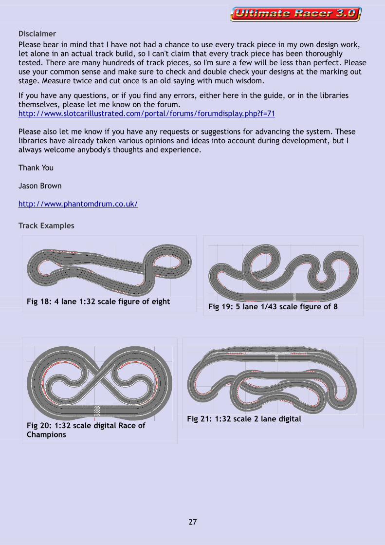
Track Examples
27
Fig 18: 4 lane 1:32 scale figure of eightFig 19: 5 lane 1/43 scale figure of 8
Fig 20: 1:32 scale digital Race of Champions
Fig 21: 1:32 scale 2 lane digital

A p p e n d i x
Tr a c k L i b r a r y D e t a i l s
SXR 1/64
Lane Width
Outer Border
Inner Kerb
Inner Border
Kerb Colours
Comparable Track
4cm 3cm 3cm 2cm Tyco, Tomy
SXR Curve Inside Radius Inner Slot Radius TYCO Curve Inside Radius Inner Slot Radius
C6 6cm 8cm 5897 - 6'' 7.6cm 9.5cm
C14 14cm 16cm 5831 - 9'' 15.2cm 17.1cm
C22 22cm 24cm 5844 - 12'' 22.9cm 24.8cm
C30 30cm 32cm 8663 - 15'' 30.5cm 32.4cm
SXR 1/43
Lane Width
Outer Border
Inner Kerb
Inner Border
Kerb Colours
Comparable Track
6cm 5cm 4cm 2cm Carrera Go, SCX Compact
SXR Curve Inside Radius Inner Slot Radius Carrera Go Curve Inside Radius Inner Slot Radius
C12 12cm 15cm R1 11.4cm 14.25cm
C24 24cm 27cm R2 22.8cm 25.65cm
C36 36cm 40cm R3 34.2cm 37.05cm
SXR 1/32
Lane Width
Outer Border
Inner Kerb
Inner Border
Kerb Colours
Comparable Track
8cm 7cm 4cm 2cm Scalextric, SCX
SXR Curve Inside Radius Inner Slot Radius Scalextric Curve Inside Radius Inner Slot Radius
C6 6cm 10cm C8202 - R1 6.0cm 9.9cm
C22 22cm 26cm C8206 - R2 21.6cm 25.5cm
C38 38cm 42cm C8204 - R3 37.1cm 41cm
C54 54cm 58cm C8235 - R4 52.7cm 56.6cm
28

SXR 1/28
Lane Width
Outer Border
Inner Kerb
Inner Border
Kerb Colours
Comparable Track
9cm 7cm 4cm 2cm Ninco
SXR Curve Inside Radius Inner Slot Radius Ninco Curve Inside Radius Inner Slot Radius
C6 6cm 10.5cm 10106 - R1 6.2cm 10.7cm
C24 24cm 28.5cm 10105 - R2 24.2cm 28.7cm
C42 42cm 46.5cm 10107 - R3 42.2cm 46.7cm
C60 60cm 64.5cm 10108 - R4 60.2cm 64.7cm
SXR 1/24
Lane Width
Outer Border
Inner Kerb
Inner Border
Kerb Colours
Comparable Track
10cm 9cm 4cm 2cm Carrera
SXR Curve Inside Radius Inner Slot Radius Carrera Curve Inside Radius Inner Slot Radius
C20 20cm 25cm 20577 - C1 20cm 25cm
C40 40cm 45cm 20572 - C2 39.8cm 44.8cm
C60 60cm 65cm 20573 - C3 59.6cm 64.6cm
C80 80cm 85cm 20578 - C4 79.4cm 84.4cm
SXR 1/24+
Lane Width
Outer Border
Inner Kerb
Inner Border
Kerb Colours
Comparable Track
11cm 10cm 4cm 2cm ISRA – min. lane width 10.4 cm
29