Embed Size (px)
Citation preview

Relion® 650 series
Switchsync™ PWC600Cyber Security Deployment Guideline


Document ID: 1MRK 511 298-UENIssued: 2013-11-12
Revision: AProduct version: 1.0
© Copyright 2013 ABB. All rights reserved

CopyrightThis document and parts thereof must not be reproduced or copied without writtenpermission from ABB, and the contents thereof must not be imparted to a thirdparty, nor used for any unauthorized purpose.
The software and hardware described in this document is furnished under a licenseand may be used or disclosed only in accordance with the terms of such license.
This product includes software developed by the OpenSSL Project for use in theOpenSSL Toolkit (http://www.openssl.org/).
This product includes cryptographic software written/developed by: Eric Young([email protected]) and Tim Hudson ([email protected]).
This product includes software provided by the jQuery Foundation(http://jquery.org/) and by the Flot project (http://www.flotcharts.org/).
TrademarksABB and Relion are registered trademarks of the ABB Group. Switchsync is atrademark of the ABB Group. All other brand or product names mentioned in thisdocument may be trademarks or registered trademarks of their respective holders.
WarrantyPlease inquire about the terms of warranty from your nearest ABB representative.
ABB AB
Substation Automation Products
SE-721 59 Västerås
Sweden
Telephone: +46 (0) 21 32 50 00
Facsimile: +46 (0) 21 14 69 18
http://www.abb.com/substationautomation

DisclaimerThe data, examples and diagrams in this manual are included solely for the conceptor product description and are not to be deemed as a statement of guaranteedproperties. All persons responsible for applying the equipment addressed in thismanual must satisfy themselves that each intended application is suitable andacceptable, including that any applicable safety or other operational requirementsare complied with. In particular, any risks in applications where a system failure and/or product failure would create a risk for harm to property or persons (including butnot limited to personal injuries or death) shall be the sole responsibility of theperson or entity applying the equipment, and those so responsible are herebyrequested to ensure that all measures are taken to exclude or mitigate such risks.
This document has been carefully checked by ABB but deviations cannot becompletely ruled out. In case any errors are detected, the reader is kindly requestedto notify the manufacturer. Other than under explicit contractual commitments, inno event shall ABB be responsible or liable for any loss or damage resulting fromthe use of this manual or the application of the equipment.

ConformityThis product complies with the directive of the Council of the EuropeanCommunities on the approximation of the laws of the Member States relating toelectromagnetic compatibility (EMC Directive 2004/108/EC) and concerningelectrical equipment for use within specified voltage limits (Low-voltage directive2006/95/EC). This conformity is the result of tests conducted by ABB inaccordance with the product standard EN 60255-26 for the EMC directive, andwith the product standards EN 60255-1 and EN 60255-27 for the low voltagedirective. The product is designed in accordance with the international standards ofthe IEC 60255 series.

Table of contents
Section 1 Introduction.......................................................................3This manual........................................................................................3Intended audience..............................................................................3Product documentation.......................................................................3
Product documentation set............................................................3Related documents..................................................................4
Document revision history.............................................................4Symbols and conventions...................................................................5
Symbols.........................................................................................5Document conventions..................................................................5
Section 2 Security in Substation Automation...................................7General security in Substation Automation........................................7
Section 3 Secure system setup........................................................9Physical interfaces..............................................................................9IP ports...............................................................................................9FTP access with SSL FTPACCS......................................................11Encryption algorithms.......................................................................11Denial of service...............................................................................11Certificate handling...........................................................................12
Section 4 Managing user roles and user accounts .......................13Authorization.....................................................................................13Predefined user roles.......................................................................14Password policies.............................................................................16IED User management.....................................................................17
Starting IED user management...................................................18General settings..........................................................................18User profile management............................................................19
Adding new users...................................................................19Adding users to new user roles..............................................22Deleting existing users...........................................................22Changing password................................................................24
User role management................................................................25Adding new users to user roles..............................................26Deleting existing users from user roles..................................26Reusing user accounts...........................................................26
Writing user management settings to the IED.............................27Reading user management settings from the IED.......................27
Table of contents
Switchsync™ PWC600 1Cyber Security Deployment Guideline

Saving user management settings..............................................28
Section 5 User activity logging.......................................................29Activity logging ACTIVLOG..............................................................29Generic security application AGSAL................................................30About Security events.......................................................................30Event types.......................................................................................30
Section 6 Local HMI use................................................................33Logging on........................................................................................33Logging off........................................................................................36Saving settings.................................................................................37Recovering password.......................................................................37
Section 7 Web HMI use..................................................................41Logging in.........................................................................................41Logging out.......................................................................................42
Section 8 IEEE Compliance statement..........................................43IEEE1686 compliance......................................................................43
Section 9 Glossary.........................................................................47
Table of contents
2 Switchsync™ PWC600Cyber Security Deployment Guideline

Section 1 Introduction
1.1 This manual
The cyber security deployment guideline describes setting up a secure system,including password procedures and levels of access in the system.
1.2 Intended audience
This guideline is intended for the system engineering, commissioning, operationand maintenance personnel handling cyber security during the engineering,installation and commissioning phases, and during normal service.
1.3 Product documentation
1.3.1 Product documentation setThe quick start guide provides basic instructions on how to use SwitchsyncPWC600. The manual provides instructions for engineering, installing,commissioning and operating, to cover the common use cases of the product.
The application manual contains descriptions of preconfigurations. The manual canbe used as a reference for configuring control, measurement, recording and LEDfunctions. The manual can also be used when creating configurations according tospecific application requirements.
The commissioning manual contains instructions on how to commission the IED.The manual can also be used by system engineers and maintenance personnel forassistance during the testing phase. The manual provides procedures for checkingof external circuitry and energizing the IED, parameter setting and configuration aswell as verifying settings by secondary injection. The manual describes the processof testing an IED in a substation which is not in service. The chapters are organizedin chronological order in which the IED should be commissioned.
The communication protocol manual describes a communication protocolsupported by the IED. The manual concentrates on vendor-specific implementations.
The cyber security deployment guideline describes setting up a secure system,including password procedures and levels of access in the system.
1MRK 511 298-UEN A Section 1Introduction
Switchsync™ PWC600 3Cyber Security Deployment Guideline

The engineering manual contains instructions on how to engineer the IEDs usingthe different tools in PCM600. The manual provides instructions on how to set up aPCM600 project and insert IEDs to the project structure. The manual alsorecommends a sequence for engineering of control functions, LHMI functions aswell as communication engineering for IEC 61850.
The installation manual contains instructions on how to install the IED. Themanual provides procedures for mechanical and electrical installation. The chaptersare organized in chronological order in which the IED should be installed.
The operation manual contains instructions on how to operate the IED once it hasbeen commissioned. The manual provides instructions for monitoring, controllingand setting the IED. The manual also describes how to identify disturbances andhow to view calculated and measured power grid data to determine the cause of afault.
The technical manual contains application and functionality descriptions and listsfunction blocks, logic diagrams, input and output signals, setting parameters andtechnical data sorted per function. The manual can be used as a technical referenceduring the engineering phase, installation and commissioning phase, and duringnormal service.
1.3.1.1 Related documents
Documents related to Switchsync PWC600 Identity numberCommunication protocol manual, IEC 61850 1MRK 511 269-UEN
Cyber Security deployment guidelines 1MRK 511 298-UEN
Installation manual 1MRK 511 272-UEN
Product guide 1MRK 511 277-UEN
Quick start guide 1MRK 511 273-UEN
Technical manual 1MRK 511 275-UEN
MICS 1MRK 511 297-WEN
PICS 1MRG 010 6601)
PIXIT 1MRG 010 6581)
TICS 1MRG 006 6071)
1) Switchsync PWC600 1.0 is based on ABB 650 series, version 1.3. So the PICS, PIXIT and TICSfrom ABB 650 series, version 1.3 are applicable for Switchsync PWC600 1.0 too.
1.3.2 Document revision historyDocument revision/date Product version HistoryA/2013-11-12 1.0 First release
Section 1 1MRK 511 298-UEN AIntroduction
4 Switchsync™ PWC600Cyber Security Deployment Guideline

1.4 Symbols and conventions
1.4.1 Symbols
The caution icon indicates important information or warning relatedto the concept discussed in the text. It might indicate the presenceof a hazard which could result in corruption of software or damageto equipment or property.
The information icon alerts the reader of important facts andconditions.
The tip icon indicates advice on, for example, how to design yourproject or how to use a certain function.
Although warning hazards are related to personal injury, it is necessary tounderstand that under certain operational conditions, operation of damagedequipment may result in degraded process performance leading to personal injuryor death. It is important that the user fully complies with all warning andcautionary notices.
1.4.2 Document conventions• Abbreviations and acronyms in this manual are spelled out in the glossary. The
glossary also contains definitions of important terms.• Push button navigation in the LHMI menu structure is presented by using the
push button icons.For example, to navigate between the options, use and .
• HMI menu paths are presented in bold.For example, select Main menu/Settings.
• LHMI messages are shown in Courier font.For example, to save the changes in non-volatile memory, select Yes andpress .
• Parameter names are shown in italics.For example, the function can be enabled and disabled with the Operation setting.
1MRK 511 298-UEN A Section 1Introduction
Switchsync™ PWC600 5Cyber Security Deployment Guideline

6

Section 2 Security in Substation Automation
2.1 General security in Substation Automation
The electric power grid has evolved significantly over the past decade thanks tomany technological advancements and breakthroughs. As a result, the emerging“smart grid” is quickly becoming a reality. At the heart of these intelligentadvancements are specialized IT systems – various control and automationsolutions such as substation automation systems. To provide end users withcomprehensive real-time information, enabling higher reliability and greatercontrol, automation systems have become ever more interconnected. To combat theincreased risks associated with these interconnections, we offer a wide range ofcyber security products and solutions for automation systems and criticalinfrastructure.
The new generation of automation systems uses open standards such as IEC60870-5-104, DNP 3.0 and IEC 61850 and commercial technologies, in particularEthernet- and TCP/IP-based communication protocols. They also enableconnectivity to external networks, such as office intranet systems and the Internet.These changes in technology, including the adoption of open IT standards, havebrought huge benefits from an operational perspective, but they have alsointroduced cyber security concerns previously known only to office or enterpriseIT systems.
To counter cyber security risks, open IT standards are equipped with cyber securitymechanisms. These mechanisms, developed in a large number of enterpriseenvironments, are proven technologies. They enable the design, development andcontinual improvement of cyber security solutions specifically for control systems,including substation automation applications.
ABB fully understands the importance of cyber security and its role in advancingthe security of substation automation systems. A customer investing in new ABBtechnologies can rely on system solutions where reliability and security have thehighest priority.
1MRK 511 298-UEN A Section 2Security in Substation Automation
Switchsync™ PWC600 7Cyber Security Deployment Guideline

Remote Control Center
(Security Zone 3)
Maintenance Center (Security Zone 4)
IEC61850-8-1 Station Bus
MicroSCADA Pro SYS600C
Firewall / Router / VPN
Firewall / Router / VPN
Encryptedcommunication
Encryptedcommunication
Perimeter Protection
Security Zone 1
Control and Protection IED
Security Zone 2
Station LAN
WorkstationAntivirus MicroSCADA Pro SYS600
Antivirus
D0E1145T201305151606 V1 EN
Figure 1: System architecture for substation automation system
Section 2 1MRK 511 298-UEN ASecurity in Substation Automation
8 Switchsync™ PWC600Cyber Security Deployment Guideline

Section 3 Secure system setup
3.1 Physical interfaces
To reduce exposure for cyber-attacks and thus comply with cyber securityrequirements, it must be possible to prevent services in the IED from operating onother physical interfaces than the ones specified by the vendor or by the owner.
3.2 IP ports
The IP port security guideline cannot suggest concrete products for a secure systemsetup. This must be decided within the specific project, requirements and existinginfrastructure. The required external equipment can be separate devices or devicesthat combine firewall, router and secure VPN functionality.
To set up an IP firewall the following table summarizes the IP ports used inSwitchsync PWC600. The ports are listed in ascending order. The column “Defaultstate” defines whether a port is open or closed by default. All ports that are closedcan be opened as described in the comment column in the table. Front and Rearrefer to the physical front and rear port. The protocol availability on these ports isconfigurable.
ABB recommends using common security measures, like firewalls, up to date antivirus software, etc. to protect the IED and the equipment around it.
Table 1: Available IP ports
Port Protocol Defaultstate
Front Rear Service Comment
21 TCP Open OFF OFF FTP (clear textpassword)
File transfer protocol
67 UDP Open ON N/A DHCP Front port only, RJ45
80 TCP Open ON ON HTTP (cleartext password)
Hypertext Transfer Protocol(Web interface)
102 TCP Open OFF ON IEC 61850 MMS communication
123 UDP Closed OFF OFF SNTP Enabled when IED isconfigured as SNTP master.
990 UDP Open ON OFF FTPS FTP with implicit SSL
7001 TCP Closed OFF OFF FST SPA protocol on TCP/IP usedby FST (Field Service Tool)
2102 TCP Open ON ON ODBC/SSL IED configuration protocol
1MRK 511 298-UEN A Section 3Secure system setup
Switchsync™ PWC600 9Cyber Security Deployment Guideline

The IEC 61850 communication protocol is enabled by configuration. This meansthat the IP port is closed and unavailable if the configuration of SwitchsyncPWC600 does not contain IEC 61850 communication functions. If a protocol isconfigured, the corresponding IP port is open all the time.
There are some restrictions and dependencies:
• The IP port used for DHCP (default UDP port 67) between the IED and acomputer is fixed and cannot be changed.
• The IP port used for IEC 61850 (default TCP port 102) is fixed and cannot bechanged.
• The IP port used for FTP (default TCP port 21) can be changed in the IED ifneeded by a 3rd party FTP client.
If the FTP port is changed PCM600 cannot be used since it is notpossible to configure it to use other IP-ports than port 21 for FTP.
• Two ports are used by PCM600. For configuration and parameter settings, theIP port for a proprietary ODBC protocol is used (TCP port 2102) and the portis fixed and cannot be changed. For Field service tool, the IP port for aproprietary SPA protocol is used (TCP port 7001) and the port is fixed andcannot be changed.
• IP routing is not possible via any of the physical interfaces.• Some IP ports are not possible to use in all physical interfaces.
GUID-95B25FB4-AADC-47BB-9B50-39A28B2A4ADC V1 EN
Figure 2: Ethernet port used for PCM600 only, front view
GUID-43B62386-2645-4F29-B056-7AC9F9FFDB1E V1 EN
Figure 3: Ethernet ports LAN1A, LAN1B, rear view COM03
Section 3 1MRK 511 298-UEN ASecure system setup
10 Switchsync™ PWC600Cyber Security Deployment Guideline

3.3 FTP access with SSL FTPACCS
The FTP Client defaults to the best possible security mode when trying to negotiatewith SSL.
The automatic negotiation mode acts on port number and server features. It tries toimmediately activate implicit SSL if the specified port is 990. If the specified portis any other, it tries to negotiate with explicit SSL via AUTH SSL/TLS.
Using FTP without SSL encryption gives the FTP client reduced capabilities. Thismode is only for accessing disturbance recorder data from the IED.
If normal FTP is required to read out disturbance recordings, createa specific account for this purpose with rights only to do Filetransfer. The password of this user will be exposed in clear text onthe wire.
3.4 Encryption algorithms
SSL/TLS connections are encrypted with AES 256 if possible or AES 128 as aminimum. At startup a negotiation decides between these two options.
No passwords are stored in clear text within the IED. An encrypted representationof the passwords with SHA 256 is stored in the IED. These are not accessible fromoutside via any ports.
3.5 Denial of service
The denial of service function is designed to limit the CPU load that can beproduced by the Ethernet network traffic on the IED. The communication facilitiesmust not be allowed to compromise the primary functionality of the device. Allinbound network traffic is quota controlled, so that a too heavy network load canbe controlled. Heavy network load might for instance be the result ofmalfunctioning equipment connected to the network.
The denial of service functions DOSFRNT, DOSLAN1 measure the IED load fromcommunication and, if necessary, limits it from jeopardizing the IED's point-on-wave control functionality due to a high CPU load. The function has the followingoutputs:
• LINKUP indicates the Ethernet link status• WARNING indicates that the data rate is higher than 3000 frames/s• ALARM indicates that the IED limits the IP-communication
1MRK 511 298-UEN A Section 3Secure system setup
Switchsync™ PWC600 11Cyber Security Deployment Guideline

For more information see related documents.
3.6 Certificate handling
A self-signed certificate is signed by the IED it certifies. Certificates useencryption to provide secure communication over the network. Certificateencryption strength depends on the certificate authority (CA).
The certificate is always trusted during communication between the IED andPCM600.
If Windows is configured to use UAC High the certificate has to be manuallytrusted in a dialog box.
Section 3 1MRK 511 298-UEN ASecure system setup
12 Switchsync™ PWC600Cyber Security Deployment Guideline
Section 4 Managing user roles and user accounts
4.1 Authorization
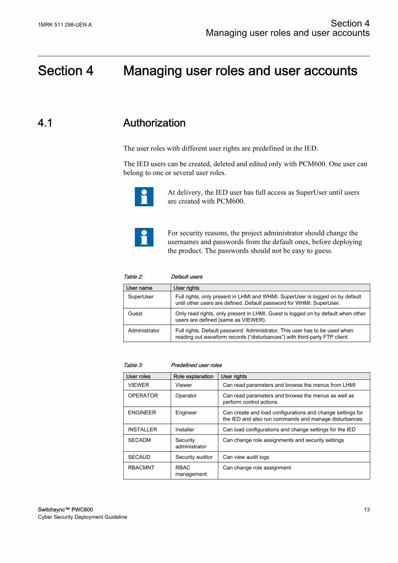
The user roles with different user rights are predefined in the IED.
The IED users can be created, deleted and edited only with PCM600. One user canbelong to one or several user roles.
At delivery, the IED user has full access as SuperUser until usersare created with PCM600.
For security reasons, the project administrator should change theusernames and passwords from the default ones, before deployingthe product. The passwords should not be easy to guess.
Table 2: Default users
User name User rightsSuperUser Full rights, only present in LHMI and WHMI. SuperUser is logged on by default
until other users are defined. Default password for WHMI: SuperUser.
Guest Only read rights, only present in LHMI. Guest is logged on by default when otherusers are defined (same as VIEWER).
Administrator Full rights. Default password: Administrator. This user has to be used whenreading out waveform records (“disturbances”) with third-party FTP client.
Table 3: Predefined user roles
User roles Role explanation User rightsVIEWER Viewer Can read parameters and browse the menus from LHMI
OPERATOR Operator Can read parameters and browse the menus as well asperform control actions
ENGINEER Engineer Can create and load configurations and change settings forthe IED and also run commands and manage disturbances
INSTALLER Installer Can load configurations and change settings for the IED
SECADM Securityadministrator
Can change role assignments and security settings
SECAUD Security auditor Can view audit logs
RBACMNT RBACmanagement
Can change role assignment
1MRK 511 298-UEN A Section 4Managing user roles and user accounts
Switchsync™ PWC600 13Cyber Security Deployment Guideline

Changes in user management settings do not cause an IED reboot.
After three consecutive failed login attempts the user will be lockedout for ten minutes before a new attempt to log in can beperformed. This time is settable 10 minutes to 60 minutes.
The PCM600 tool caches the login credentials after successful loginfor 15 minutes. During that time no more login will be necessary.
4.2 Predefined user roles
There are different roles of users that can access or operate different areas of theIED and tool functionalities.
Ensure that the user logged on to the IED has the required accesswhen writing particular data to the IED from PCM600. For moreinformation about setting user access rights, see the PCM600documentation.
The meaning of the legends used in the table:
• X= Full access rights• R= Only reading rights• - = No access rights
Table 4: Predefined user roles
Access rights VIEWER OPERATOR ENGINEER INSTALLER SECADM SECAUD RBACMNTConfig – Basic - - X X - - -
Config – Advanced - - X X - - -
FileTransfer – Tools - - X X - - -
UserAdministration - - - - X - X
Setting – Basic R R X X - - -
Setting – Advanced R R X X - - -
Control – Basic - X X - - - -
Control – Advanced - X X - - - -
IEDCmd – Basic - X X - - - -
IEDCmd – Advanced - - X - - - -
FileTransfer – Limited - X X X X X X
Table continues on next page
Section 4 1MRK 511 298-UEN AManaging user roles and user accounts
14 Switchsync™ PWC600Cyber Security Deployment Guideline

Access rights VIEWER OPERATOR ENGINEER INSTALLER SECADM SECAUD RBACMNTDB Access normal - X X X X X X
Audit log read - - - - - X -
Setting – Change Setting Group - X X X - - -
Security Advanced - - - - - X -
Table 5: Access rights explanation
Access rights ExplanationConfig – Basic Configuration – Basic is intended for engineers that only adapt an existing configuration e.g. the I/
O-Configuration using SMT
Config – Advanced Configuration – Advanced is intended for engineers that do the whole application engineeringand using e.g. ACT
FileTransfer – Tools FileTransfer – Tools is used for some configuration files for the configuration and shall have thesame value as Config – Advanced
UserAdministration UserAdministration is used to handle user management e.g. adding new user
Setting – Basic Setting – Basic is used for basic settings e.g. control settings and limit supervision
Setting – Advanced Setting – Advanced is used for the relay engineer to set settings e.g. for the protection functions
Control – Basic Control – Basic is used for a normal operator without possibility to bypass safety functions e.g.interlock or synchro-check bypass
Control – Advanced Control – Advanced is used for an operator that is trusted to do process commands that can bedangerous
IEDCmd – Basic IEDCmd – Basic is used for commands to the IED that are not critical e.g. Clear LEDs, manualtriggering of disturbances
IEDCmd – Advanced IEDCmd – Advanced is used for commands to the IED that can hide information e.g. Cleardisturbance record
FileTransfer – Limited FileTransfer - Limited is used for access to disturbance files e.g. through FTP
DB Access normal Database access for normal user. This is needed for all users that access data from PCM
Audit log read Audit log read allows reading the audit log from the IED
Setting – Change Setting Group Setting – Change Setting Group is separated to be able to include the possibility to change thesetting group without changing any other setting
Security Advanced Security Advanced is the privilege required to do some of the more advanced security-relatedsettings
IED users can be created, deleted and edited only with the IED Users tool withinPCM600. Logging on or off can only be done on the local HMI on the IED, thereare no users, roles or rights that can be defined on local HMI.
At delivery, the IED has a default user defined with full access rights. PCM600uses this default user to access the IED. This user is automatically removed in IEDwhen users are defined via the IED Users tool in PCM600.
Default User ID: Administrator
Password: Administrator
1MRK 511 298-UEN A Section 4Managing user roles and user accounts
Switchsync™ PWC600 15Cyber Security Deployment Guideline

Only characters A - Z, a - z and 0 - 9 shall be used in user names.User names are not case sensitive. For passwords see the Passwordpolicies in PCM600.
First user created must be appointed the role SECADM to be ableto write users, created in PCM600, to the IED.
In order to allow the IED to communicate with PCM600 whenusers are defined via the IED Users tool, the access rights“UserAdministration” and “FileTransfer - Limited” must be appliedto at least one user.
4.3 Password policies
Only ASCII characters are allowed when typing username or password. Currently,characters in the range 32-126 and 192-383 (ASCII ranges, decimal) are supported.
Password policies are set in the IED Users tool in PCM600. There are severaloptions for forcing the password safer.
• Minimum length of password (1 - 12)• Require lowercase letters ( a - z )• Require uppercase letters ( A - Z )• Require numeric letters ( 0 - 9 )• Require special characters ( !@#+”*%&/=? )
To achieve IEEE 1686 conformity, a password with a minimumlength of eight characters must be used, and the check box EnforcePassword Policies shall be ticked.
Settings for password lifetime are not supported in this release.
Section 4 1MRK 511 298-UEN AManaging user roles and user accounts
16 Switchsync™ PWC600Cyber Security Deployment Guideline

IEC13000027-1-en.vsdD0E1154T201305151606 V1 EN
Figure 4: Change Password Policies dialog box in IED Users tool in PCM600
4.4 IED User management
The IED Users tool in PCM600 is used for editing user profiles and role assignments.
In the IED Users tool, the data can be retrieved from an IED or data can be writtento an IED if permitted. The data from an IED can be saved to the project database.
Always use Read User Management Settings from IED beforemaking any changes when managing user profiles. If this is notdone password changes made by users may be lost!
Nothing is changed in the IED until a “writing-to-IED operation” isperformed.
1MRK 511 298-UEN A Section 4Managing user roles and user accounts
Switchsync™ PWC600 17Cyber Security Deployment Guideline

4.4.1 Starting IED user management• Connect the PC to the IED.• Start PCM600.• Select an IED in the object tree.• Select Tools/IED Users or right-click an IED in the object tree and select IED
Users. The IED User dialog box appears.
4.4.2 General settingsIn the General tab, by clicking Restore factory settings the default users can berestored in the IED Users tool. For Switchsync PWC600 this means reverting backto the factory delivered users. Performing this operation does not remove the usersin the IED. Nothing is changed in the IED until a “writing-to-IED operation” isperformed.
This is not the same action as Revert to IED defaults in therecovery menu.
The previous administrator user ID and password have to be given so that thewriting toward the IED can be done.
Editing can be continued by clicking Restore factory settings when not connectedto the IED.
D0E1070T201305151606 V1 EN
Figure 5: General tab
Section 4 1MRK 511 298-UEN AManaging user roles and user accounts
18 Switchsync™ PWC600Cyber Security Deployment Guideline
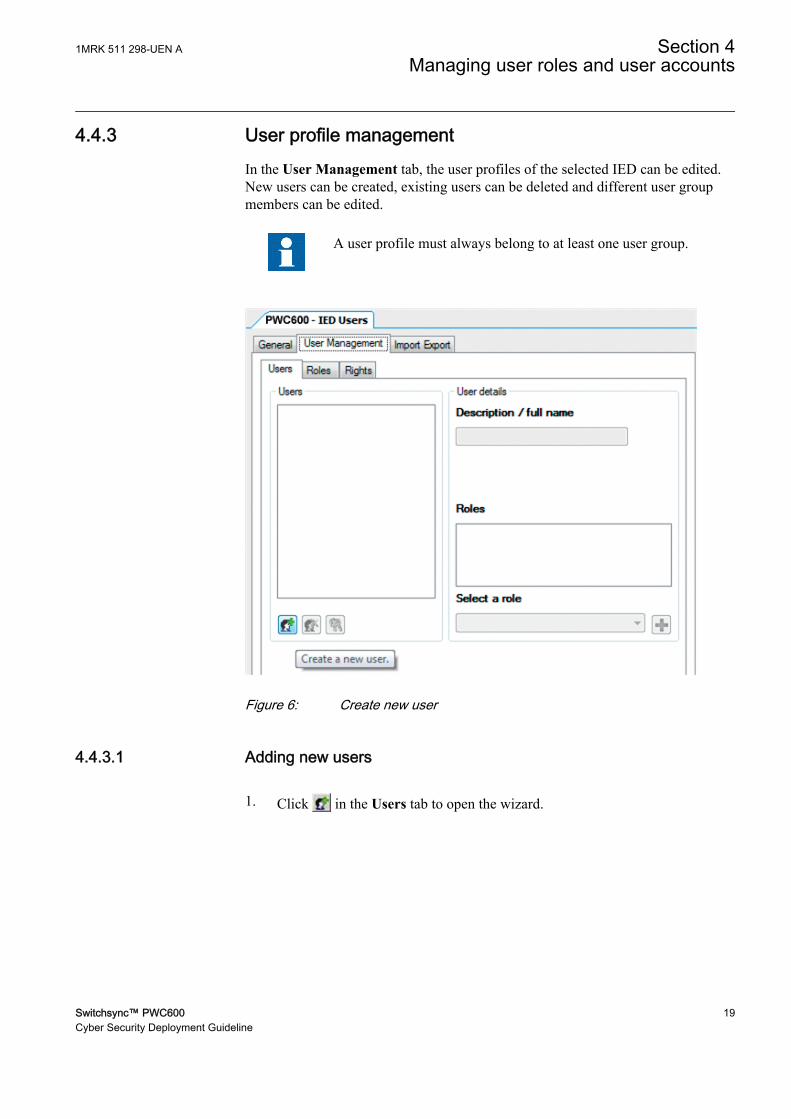
4.4.3 User profile managementIn the User Management tab, the user profiles of the selected IED can be edited.New users can be created, existing users can be deleted and different user groupmembers can be edited.
A user profile must always belong to at least one user group.
D0E1109T201305151606 V1 EN
Figure 6: Create new user
4.4.3.1 Adding new users
1. Click in the Users tab to open the wizard.
1MRK 511 298-UEN A Section 4Managing user roles and user accounts
Switchsync™ PWC600 19Cyber Security Deployment Guideline

IEC12000200-1-en.vsdD0E1112T201305151606 V1 EN
Figure 7: Create new user
2. Follow the instructions in the wizard to define a user name, password anduser group. Select at least one user group where the defined user belongs. Theuser profile can be seen in the User details field.
Section 4 1MRK 511 298-UEN AManaging user roles and user accounts
20 Switchsync™ PWC600Cyber Security Deployment Guideline

IEC12000201-1-en.vsdD0E1115T201305151606 V1 EN
Figure 8: Select user groups
3. Select the user from the user list and type a new name or description in theDescription/full name field to change the name or description of the user.
D0E1118T201305151606 V1 EN
Figure 9: Enter description
1MRK 511 298-UEN A Section 4Managing user roles and user accounts
Switchsync™ PWC600 21Cyber Security Deployment Guideline
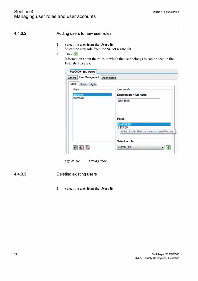
4.4.3.2 Adding users to new user roles
1. Select the user from the Users list.2. Select the new role from the Select a role list.3. Click .
Information about the roles to which the user belongs to can be seen in theUser details area.
D0E1121T201305151606 V1 EN
Figure 10: Adding user
4.4.3.3 Deleting existing users
1. Select the user from the Users list.
Section 4 1MRK 511 298-UEN AManaging user roles and user accounts
22 Switchsync™ PWC600Cyber Security Deployment Guideline

D0E1058T201305151606 V1 EN
Figure 11: Select user to be deleted
2. Click .
D0E1061T201305151606 V1 EN
Figure 12: Delete existing user
1MRK 511 298-UEN A Section 4Managing user roles and user accounts
Switchsync™ PWC600 23Cyber Security Deployment Guideline

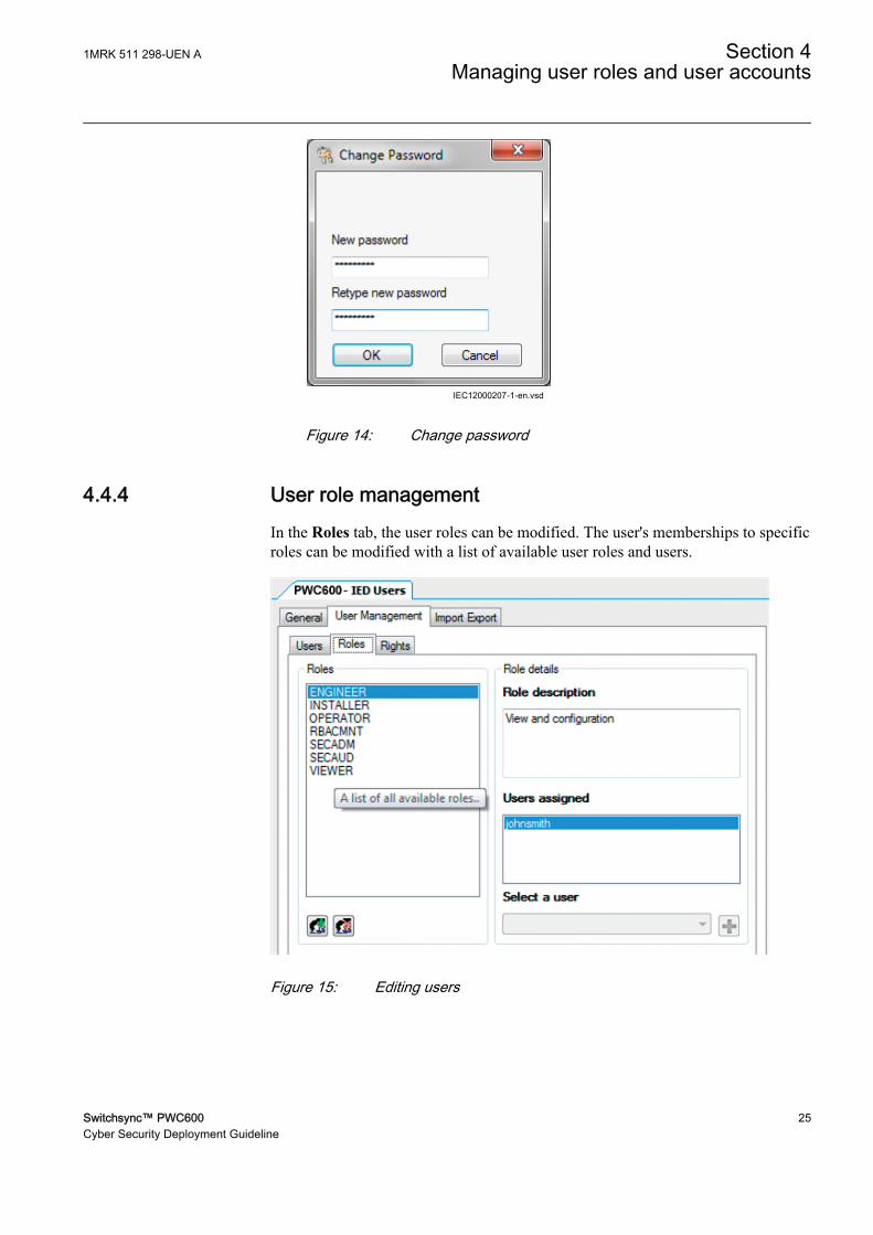
4.4.3.4 Changing password
1. Select the user from the Users list.
D0E1124T201305151606 V1 EN
Figure 13: Select user
2. Click .3. Type the old password once and the new password twice in the required
fields.The passwords can be saved in the project database or sent directly to the IED.
No passwords are stored in clear text within the IED. A hashrepresentation of the passwords is stored in the IED and it isnot accessible from outside via any ports.
Section 4 1MRK 511 298-UEN AManaging user roles and user accounts
24 Switchsync™ PWC600Cyber Security Deployment Guideline
IEC12000207-1-en.vsdD0E1127T201305151606 V1 EN
Figure 14: Change password
4.4.4 User role managementIn the Roles tab, the user roles can be modified. The user's memberships to specificroles can be modified with a list of available user roles and users.
D0E1064T201305151606 V1 EN
Figure 15: Editing users
1MRK 511 298-UEN A Section 4Managing user roles and user accounts
Switchsync™ PWC600 25Cyber Security Deployment Guideline

4.4.4.1 Adding new users to user roles
1. Select the required role from the Roles list.The role profile can be seen under the Role details field.
2. Select the new user from the Select a user list.3. Click .
The new user is shown in the Users assigned list.
4.4.4.2 Deleting existing users from user roles
1. Right-click the user in the Users assigned list.2. Select Remove this Role from Selected Member.
D0E1130T201305151606 V1 EN
Figure 16: Remove Role from User
4.4.4.3 Reusing user accounts
IED user account data can be exported from one IED and imported to another. Thedata is stored in an encrypted file.
To export IED user account data from an IED
1. Click the Import Export tab in the IED User tool in PCM600.2. Click Export IED account data.
The user account data is exported to a file with user defined filename and location.
Section 4 1MRK 511 298-UEN AManaging user roles and user accounts
26 Switchsync™ PWC600Cyber Security Deployment Guideline

Import IED user rights to an IED
1. Click Import IED account data.2. Open the previously exported file.
Only users who have the right to change the user account data in PCM600 areallowed to export and import.
D0E1148T201305151606 V1 EN
Figure 17: Importing and exporting user account data
4.4.5 Writing user management settings to the IED• Click the Write User Management Settings to IED button on the toolbar.
D0E1067T201305151606 V1 EN
Figure 18: Write to IED
The data is saved when writing to the IED starts.
4.4.6 Reading user management settings from the IED• Click the Read User Management Settings from IED button on the toolbar.
1MRK 511 298-UEN A Section 4Managing user roles and user accounts
Switchsync™ PWC600 27Cyber Security Deployment Guideline

4.4.7 Saving user management settings• From the File menu, select Save.• Click the Save toolbar button.
The save function is enabled only if the data has changed.
Section 4 1MRK 511 298-UEN AManaging user roles and user accounts
28 Switchsync™ PWC600Cyber Security Deployment Guideline

Section 5 User activity logging
5.1 Activity logging ACTIVLOG
ACTIVLOG contains all settings for activity logging.
There can be 6 external log servers to send syslog events to. Each server can beconfigured with IP address; IP port number and protocol format. The format can beeither syslog (RFC 5424) or Common Event Format (CEF) from ArcSight.
Table 6: ACTIVLOG Non group settings (basic)
Name Values (Range) Unit Step Default DescriptionExtLogSrv1Type Off
SYSLOG UDP/IPSYSLOG TCP/IPCEF TCP/IP
- - Off External log server 1 type
ExtLogSrv1Port 1 - 65535 - 1 514 External log server 1 port number
ExtLogSrv1IP 0 - 18 IPAddress
1 127.0.0.1 External log server 1 IP-address
ExtLogSrv2Type OffSYSLOG UDP/IPSYSLOG TCP/IPCEF TCP/IP
- - Off External log server 2 type
ExtLogSrv2Port 1 - 65535 - 1 514 External log server 2 port number
ExtLogSrv2IP 0 - 18 IPAddress
1 127.0.0.1 External log server 2 IP-address
ExtLogSrv3Type OffSYSLOG UDP/IPSYSLOG TCP/IPCEF TCP/IP
- - Off External log server 3 type
ExtLogSrv3Port 1 - 65535 - 1 514 External log server 3 port number
ExtLogSrv3IP 0 - 18 IPAddress
1 127.0.0.1 External log server 3 IP-address
ExtLogSrv4Type OffSYSLOG UDP/IPSYSLOG TCP/IPCEF TCP/IP
- - Off External log server 4 type
ExtLogSrv4Port 1 - 65535 - 1 514 External log server 4 port number
ExtLogSrv4IP 0 - 18 IPAddress
1 127.0.0.1 External log server 4 IP-address
ExtLogSrv5Type OffSYSLOG UDP/IPSYSLOG TCP/IPCEF TCP/IP
- - Off External log server 5 type
ExtLogSrv5Port 1 - 65535 - 1 514 External log server 5 port number
Table continues on next page
1MRK 511 298-UEN A Section 5User activity logging
Switchsync™ PWC600 29Cyber Security Deployment Guideline

Name Values (Range) Unit Step Default DescriptionExtLogSrv5IP 0 - 18 IP
Address1 127.0.0.1 External log server 5 IP-address
ExtLogSrv6Type OffSYSLOG UDP/IPSYSLOG TCP/IPCEF TCP/IP
- - Off External log server 6 type
ExtLogSrv6Port 1 - 65535 - 1 514 External log server 6 port number
ExtLogSrv6IP 0 - 18 IPAddress
1 127.0.0.1 External log server 6 IP-address
5.2 Generic security application AGSAL
As a logical node AGSAL is used for monitoring security violation regardingauthorization, access control and inactive association including authorizationfailure. Therefore, all the information in AGSAL can be configured to report to61850 client.
5.3 About Security events
Relevant user operations are logged as security events. A security event contains anevent ID, a time stamp, a sequence number, the user name, the severity of theaction and the name of the source. These events can be sent to external security logservers using Syslog. The log servers are configured from PCM600. Syslog is astandard protocol for event logging.
To be able to access the security logs the user need the roleSECAUD (security auditor) or the access right “Audit log read”.
5.4 Event types
All user activities are logged and stored according to IEC 61850.
Table 7: Event type codes
Event number Acronyms GSAL mapping English1110 LOGIN_OK GSAL.Ina Login successful
1130 LOGIN_FAIL_WRONG_CR GSAL.AuthFail Login failed - Wrong credentials
1170 LOGIN_FAIL_3_TIMES GSAL.AuthFail Login failed 3 times
1210 LOGOUT_USER GSAL.Ina Logout (user logged out)
1220 LOGOUT_TIMEOUT GSAL.Ina Logout by user inactivity (timeout)
Table continues on next page
Section 5 1MRK 511 298-UEN AUser activity logging
30 Switchsync™ PWC600Cyber Security Deployment Guideline

Event number Acronyms GSAL mapping English1460 PARAM_CHANGE_FAIL_RIGHTS GSAL.AcsCtlFail Parameter changes failed — no rights
1710 CONFIG_RESET_FACTORY_DEF GSAL.Ina Device reset to factory default
2110 USER_ACCNT_CREATE_OK GSAL.Ina User account created successfully
2120 USER_ACCNT_DEL_OK GSAL.Ina User account deleted successfully
2130 USER_ACCNT_CREATE_FAIL GSAL.SvcViol User account creation failed
2140 USER_ACCNT_DEL_FAIL GSAL.SvcViol User account deletion failed
2160 USER_NEW_ROLE_OK GSAL.Ina New role assigned to usersuccessfully
2170 USER_ROLE_REMOVED_OK User role assignment removedsuccessfully
2210 USER_PW_CHANGE_OK GSAL.SvcViol User password changed successfully
2220 USER_PW_CHANGE_FAIL GSAL.SvcViol Change of user password failed
5110 MANUAL_RESET GSAL.Ina Manual reset
5120 RESET_TRIPS GSAL.Ina Reset trips
5130 RESET_LEDS GSAL.Ina Reset LEDs
5270 SYS_STARTUP GSAL.Ina System startup
5280 SYS_SHUTTING_DOWN GSAL.Ina System shutting down
6110 TEST_MODE_START_OK Test mode started
6120 TEST_MODE_END Test mode ended
6130 CONTRL_OP_PERF_OK Control operation performed
6132 CONTRL_OP_PERF_FAIL Control operation attempt failed
6140 SIGN_FORCED_VALUE Signal forced — value changed
7310 HW_CHANGE_DETECTED Hardware change detected
8020 DATE_TIME_SET_OK Date and time set successfully
8230 NEW_CERT_GEN_FAIL New certificate generation failed
9010 ATT_DET_FLOODING Flooding attack detected
10010 MAINT_ENTER_MENU_EV Device entered maintenance menudue to user action
10020 MAINT_FORCED_MENU_OK Device successfully forced intomaintenance menu due to new state
10030 MAINT_FTP_ACTIV_OK FTP server successfully activatedfrom maintenance menu
10040 MAINT_UPDATE_ABORT_OK Firmware update procedure abortedsuccessfully
10050 MAINT_RECOVERY_ENTER_OK Recovery menu entered successfully
10052 MAINT_RECOVERY_ENTER_FAIL Entering Recovery menu failed
10060 MAINT_AUTH_DIS_OK Authentication disabled frommaintenance menu successfully
10070 MAINT_CHANGE_LOCK_DIS_OK Change lock disabled successfullyfrom Maintenance menu
10080 MAINT_61850_DIS_OK IEC 61850 disabled successfullyfrom Maintenance menu
Table continues on next page
1MRK 511 298-UEN A Section 5User activity logging
Switchsync™ PWC600 31Cyber Security Deployment Guideline

Event number Acronyms GSAL mapping English13200 TRANSFER_CONFIG_OK Configuration transferred to the
device successfully
13210 TRANSFER_CONFIG_STARTED_OK Configuration transfer to the devicestarted
13300 READ_CONFIG_OK Configuration files read/exportedfrom the device successfully
13310 READ_CONFIG_STARTED_OK Configuration exporting from thedevice started successfully
13400 TRANSFER_FIRMW_OK Firmware transferred to the devicesuccessfully
13500 READ_FIRMW_OK Firmware files read/exported fromthe device successfully
13520 TRANSFER_CERTS_OK Certificates transferred to the devicesuccessfully
13580 READ_CERTS_OK Exported/read certificates fromdevice successfully
14200 TRANSFER_CONFIG_FAIL Failed to transfer configuration to thedevice
14300 READ_CONFIG_FAIL Failed to read configuration files fromthe device
14400 TRANSFER_FIRMW_FAIL Failed to transfer firmware to thedevice
14500 READ_FIRMW_FAIL Failed to read firmware files from thedevice
14520 TRANSFER_CERTS_FAIL Failed to transfer certificates to thedevice
14580 READ_CERTS_FAIL Failed to read certificates from thedevice
Section 5 1MRK 511 298-UEN AUser activity logging
32 Switchsync™ PWC600Cyber Security Deployment Guideline

Section 6 Local HMI use
At delivery, logging on is not required and the user has full access until users andpasswords are created with PCM600 and written into the IED. The LHMI is loggedon as SuperUser by default until other users are defined.
Commands, changing parameter values and resetting indications, for example, areactions requiring password when the password protection is activated. Readinginformation on the LHMI is always allowed without password. The LHMI islogged on as Guest by default when other users are defined.
Utility security policies and practical consideration should alwaysbe taken on the feasibility of using passwords. In emergencysituations, the use of passwords could delay urgent actions. Whensecurity issues must be met, the two factors must be seriouslyconsidered.
The auxiliary power supply to the IED must not be switched offbefore changes such as passwords, setting parameter or local/remote control state changes are saved.
6.1 Logging on
1. Press to activate the logon procedure.The logon is also activated when attempting a password-protected operation.
2. Select the user name by scrolling with and .
1MRK 511 298-UEN A Section 6Local HMI use
Switchsync™ PWC600 33Cyber Security Deployment Guideline

D0E1094T201305141540 V1 EN
Figure 19: Selecting the user name
3. Enter the password when prompted and select OK.
• Activate the character to be entered with and .• Enter the character with and .
Upper and lower case letters are also found by scrolling the 255 characterswith and .
D0E1091T201305141540 V1 EN
Figure 20: Entering the password
Passwords are case sensitive.
Section 6 1MRK 511 298-UEN ALocal HMI use
34 Switchsync™ PWC600Cyber Security Deployment Guideline

Only characters A - Z, a - z and 0 - 9 shall be used in usernames. User names are not case sensitive. For passwords seethe Password policies in PCM600.
4. Press to confirm the logon or to cancel the procedure.If the logon fails, a message is displayed on the display.
D0E1299T201305141540 V1 EN
Figure 21: Error message indicating an incorrect password
The logon dialog appears if the attempted operation requiresanother level of user rights.
Once a user is created and written into the IED, logon is possiblewith the password assigned in the tool. If there is no user created,an attempt to log on causes the display to show a correspondingmessage.
1MRK 511 298-UEN A Section 6Local HMI use
Switchsync™ PWC600 35Cyber Security Deployment Guideline
D0E1305T201305141540 V1 EN
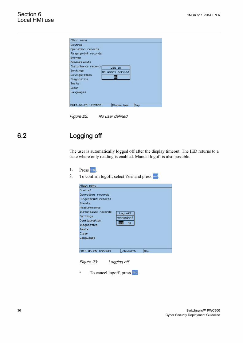
Figure 22: No user defined
6.2 Logging off
The user is automatically logged off after the display timeout. The IED returns to astate where only reading is enabled. Manual logoff is also possible.
1. Press .2. To confirm logoff, select Yes and press .
D0E1302T201305141540 V1 EN
Figure 23: Logging off
• To cancel logoff, press .
Section 6 1MRK 511 298-UEN ALocal HMI use
36 Switchsync™ PWC600Cyber Security Deployment Guideline

6.3 Saving settings
Editable values are stored in the non-volatile flash memory. Most of the parameterchanges take effect immediately after storing, but some parameter changes requireapplication restart. Values stored in the flash memory remain in effect after rebootas well.
1. Press to confirm any changes.2. Press to move upwards in the menu tree or to enter the Main Menu.3. To save the changes in non-volatile memory, select Yes and press .
D0E1001T201305141540 V1 EN
Figure 24: Confirming settings
• To exit without saving changes, select No and press .• To cancel saving settings, select Cancel and press .
Pressing Cancel in the Save changes dialog closes only the Savechanges dialog box, but the IED remains in editing mode. All thechanges applied to any setting are not lost and the user can continueto change settings. To leave the change setting mode, select No orYes in the Save changes dialog.
After changing the parameters marked with !, the IED restartsautomatically for the changes to take effect.
6.4 Recovering password
In case of password loss or any other file system error that prevents the IED fromworking properly, the whole file system can be restored to IED default state. Allthe default settings and configuration files stored in the IED at the factory arerestored. One important usage of this menu is to disable the authority system. Thiscan be used to recover an IED where the user-defined passwords are lost
It is possible to disable the Maintenance menu. This is done by setting theparameter MaintMenuEnable to No in the Group AUTHMAN: 1 using theParameter settings in PCM600.
1MRK 511 298-UEN A Section 6Local HMI use
Switchsync™ PWC600 37Cyber Security Deployment Guideline

If the Maintenance menu is disabled, there is no way to bypassauthority if passwords are forgotten. To be able to do fieldupdating; the maintenance menu have to be re-enabled.
To enter this menu, the IED must be rebooted and a specific key combination mustbe pressed on the LHMI during the IED boot sequence.
1. Switch off the power supply to the IED and leave it off for one minute.2. Switch on the power supply to the IED and press and hold down and
until the Maintenance Menu appears on the LHMI (this takes around 20-60s).3. Navigate down and select Recovery Menu and press or .
IEC12000168-1-en.vsdD0E1136T201305151606 V1 EN
Figure 25: Select Recovery menu
4. Enter PIN code 8282 and press .
IEC13000036-1-en.vsdD0E1157T201305151606 V1 EN
Figure 26: Enter PIN code
5. Select Turn off authority and press or .
Section 6 1MRK 511 298-UEN ALocal HMI use
38 Switchsync™ PWC600Cyber Security Deployment Guideline

IEC12000170-1-en.vsdD0E1142T201305151606 V1 EN
Figure 27: Turn off Authority
6. Select OK to turn off the authority and press .
IEC12000169-1-en.vsdD0E1139T201305151606 V1 EN
Figure 28: Confirm selection
7. Press to continue the startup sequence, (now the authority is temporarilydisabled until next reboot of the IED).
To cancel the operation in any step, press .
Open PCM600 and start the IED Users tool.
• Remove the faulty user• Create a new user with the same access rights• Write the user management settings to the IED
1MRK 511 298-UEN A Section 6Local HMI use
Switchsync™ PWC600 39Cyber Security Deployment Guideline

The IED perform a reboot, new settings are activated and the authority system isenabled again.
The Maintenance Menu is only available on the Local HMI. Thepurpose of this menu is to have a way to recover in the field atdifferent situations. The recovery menu is also protected with a 4–digit PIN code, fixed for all IEDs.
Avoid unnecessary restoring of factory IED default setting (Revertto IED defaults), since all parameter settings earlier written to theIED are overwritten with factory default values.
When Revert to IED defaults is selected the IED restores thefactory IED default settings and restarts. Restoring can take severalminutes. Confirmation of the restored factory IED default settingsis shown on the display for a few seconds, after which the IED restarts.
Section 6 1MRK 511 298-UEN ALocal HMI use
40 Switchsync™ PWC600Cyber Security Deployment Guideline

Section 7 Web HMI use
7.1 Logging in
1. Connect to the IED by typing the IP address into the browser’s address field.A blank page with only the Login button is displayed.
GUID-12D4941A-7D5D-4EDE-B138-4D790F8763B9 V1 EN
Figure 29: Initial view for logging into WHMI
For security reasons, no information about the IED is shownuntil the user has successfully logged in.
If the dialog box for entering user credentials does not open automatically,click the Login button.
2. Type the username.3. Type the password.4. Click OK.
1MRK 511 298-UEN A Section 7Web HMI use
Switchsync™ PWC600 41Cyber Security Deployment Guideline

GUID-8393D0D9-00DD-488B-9A15-6F32A423D627 V1 EN
Figure 30: Entering username and password
The Web client timeout is set in the Web server. The default timeout is 15minutes.
If wrong login credentials are entered for 3 times, server redirects toan error page.
7.2 Logging out
• To logout, click Logout on the menu bar.
GUID-F2987898-7B18-48DF-847E-D7D933131753 V1 EN
Figure 31: Logout
Section 7 1MRK 511 298-UEN AWeb HMI use
42 Switchsync™ PWC600Cyber Security Deployment Guideline

Section 8 IEEE Compliance statement
8.1 IEEE1686 compliance
Table 8: IEEE1686 compliance
Clause Title Status Comment5 IED cyber security
featuresAcknowledge
5.1 Electronic accesscontrol
Comply Access is protected for local accessthrough control panel. Access isprotected for local access through acommunication /diagnostic port.Access is protected for remoteaccess through a communicationmedia
5.1.1 Password defeatmechanisms
Comply
5.1.2 Number of individualID/passwordssupported
Comply 20 unique ID/password combinationsare supported
5.1.3 Passwordconstruction
Comply The minimum enforced passwordlength is configurable. If passwordpolicy is enforced, minimum is 6.Use of mix of lower andUPPERCASE characters isenforced, configurable in passwordpolicies Use of numerical values isenforced, configurable in passwordpolicies. Use of non-alphanumericcharacter (e.g. @, #, %, &, *) isenforced, configurable in passwordpolicies
5.1.4 Authorization levelsby password
Comply
5.1.4.1 View data Comply View data feature is accessiblethrough individual user accounts
5.1.4.2 View configurationsettings
Comply View configuration settings feature isaccessible through individual useraccounts
5.1.4.3 Force values Comply Force value feature is accessiblethrough individual user accounts
5.1.4.4 Configuration change Comply Configuration feature is accessiblethrough individual user accounts
5.1.4.5 Firmware change Comply Firmware change feature isaccessible through individual useraccounts
5.1.4.6 ID/passwordmanagement
Comply User account (ID / password)management feature is accessiblethrough individual user accounts.
Table continues on next page
1MRK 511 298-UEN A Section 8IEEE Compliance statement
Switchsync™ PWC600 43Cyber Security Deployment Guideline

Clause Title Status Comment5.1.4.7 Audit log Comply Audit log view / download feature is
accessible through individual useraccounts
5.1.5 Password display Comply
5.1.6 Access time-out Comply A time-out feature exists. The timeperiod is configurable by the user.
5.2 Audit trail Comply The Audit log can be viewed throughPCM 600
5.2.1 Storage capability Comply
5.2.2 Storage record Comply
5.2.2.1 Event record number Comply
5.2.2.2 Time and date Comply
5.2.2.3 User ID Comply
5.2.2.4 Event type Comply
5.2.3 Audit trail event types Comply
5.2.3.1 Login Comply
5.2.3.2 Manual logout Comply
5.2.3.3 Timed logout Comply
5.2.3.4 Value forcing Comply
5.2.3.5 Configuration access Comply
5.2.3.6 Configuration change Comply
5.2.3.7 Firmware change Comply
5.2.3.8 ID/password creationor modification
Comply
5.2.3.9 ID/password deletion Comply
5.2.3.10 Audit-log access Comply
5.2.3.11 Time/date change Comply
5.2.3.12 Alarm incident Comply
5.3 Supervisorymonitoring and control
Comply
5.3.1 Events Exception Automated time changes and read ofconfiguration are not reported;otherwise compliance
5.3.2 Alarms Exception No Client certificates are in use
5.3.2.1 Unsuccessful loginattempt
Comply
5.3.2.2 Reboot Comply
5.3.2.3 Attempted use ofunauthorizedconfiguration software
Exception Not supported
5.3.2.4 Alarm point changedetect
Comply
5.3.4 Event and alarmgrouping
Exception Not supported
Table continues on next page
Section 8 1MRK 511 298-UEN AIEEE Compliance statement
44 Switchsync™ PWC600Cyber Security Deployment Guideline

Clause Title Status Comment5.3.5 Supervisory
permissive controlException Not supported
5.4 Configurationsoftware
Acknowledge
5.4.1 Authentication Exception Configuration download is handledby authentication
5.4.2 ID/password control Comply
5.4.3 ID/password-controlled features
Comply
5.4.3.1 View configurationdata
Comply
5.4.3.2 Change configurationdata
Comply
5.4.3.3 Full access Comply
5.5 Communications portaccess
Comply
5.6 Firmware qualityassurance
Exception Quality control is handled accordingto ISO9001 and CMMI.
1MRK 511 298-UEN A Section 8IEEE Compliance statement
Switchsync™ PWC600 45Cyber Security Deployment Guideline

46

Section 9 Glossary
AES Advanced Encryption Standard (AES) is a specification for theencryption of electronic data. The key size used for an AEScipher specifies the number of repetitions of transformationrounds that convert the input, called the plaintext, into the finaloutput, called the ciphertext. The number of cycles ofrepetition are as follows: 10 cycles of repetition for 128-bitkeys. 12 cycles of repetition for 192-bit keys. 14 cycles ofrepetition for 256-bit keys.
ACT Application configuration tool within PCM600
AGSAL Generic security application
ANSI American National Standards Institute
ASCII American Standard Code for Information Interchange (ASCII)is a character-encoding scheme originally based on the Englishalphabet. ASCII codes represent text in computers,communications equipment, and other devices that use text.
CA In cryptography, certificate authority, or certificationauthority, (CA) is an entity that issues digital certificates. Thedigital certificate certifies the ownership of a public key by thenamed subject of the certificate
CMT Communication Management tool in PCM600
CPU Central processor unit
CRC Cyclic redundancy check
DARPA Defense Advanced Research Projects Agency (The USdeveloper of the TCP/IP protocol etc.)
DHCP Dynamic Host Configuration Protocol
DNP3 DNP3 (Distributed Network Protocol) is a set ofcommunications protocols used between components inprocess automation systems. Its main use is in utilities such aselectric and water companies. It plays a crucial role in SCADAsystems, where it is used by SCADA Master Stations (akaControl Centers), Remote Terminal Units (RTUs), andIntelligent Electronic Devices (IEDs). It is primarily used forcommunications between a master station and RTUs or IEDs'.
EMC Electromagnetic compatibility
EN European standard
EN 50263 Electromagnetic compatibility (EMC) - Product standard formeasuring relays and protection equipment.
1MRK 511 298-UEN A Section 9Glossary
Switchsync™ PWC600 47Cyber Security Deployment Guideline

EN 60255-26 Electromagnetic compatibility (EMC) - Product standard formeasuring relays and protection equipment.
EN 60255-27 Electromagnetic compatibility (EMC) - Product standard formeasuring relays and protection equipment.
ESD Electrostatic discharge
FST Field Service Tool
FTP File Transfer Protocol (FTP) is a standard network protocolused to transfer files from one host or to another host over a TCP-based network, such as the Internet.
FTPS FTPS (also known as FTP-ES, FTP-SSL and FTP Secure) isan extension to the commonly used File Transfer Protocol(FTP) that adds support for the Transport Layer Security(TLS) and the Secure Sockets Layer (SSL) cryptographicprotocols.
GDE Graphical display editor within PCM600
GOOSE Generic object-oriented substation event
GPS Global positioning system
GSM GPS time synchronization module
GTM GPS Time Module
HMI Human-machine interface
HTTP Hypertext transfer protocol
HW Hardware
ID IDentification
IED Intelligent electronic device
IEC International Electrical Committee
IEC 60255 This standard specifies the general performance requirementsof all electrical measuring relays and protection equipmentused in the electrotechnical fields covered by the IEC.
IEC 60870-5-103 Communication standard for protective equipment. A serialmaster/slave protocol for point-to-point communication
IEC 61850 Substation automation communication standard
IEC 61850-8-1 Communication protocol standard
IEC61850-9-2(LE)
Communication protocol standard for sampled values
IED Intelligent electronic device
IEDUM IED User Management
IEEE Institute of Electrical and Electronics Engineers
Section 9 1MRK 511 298-UEN AGlossary
48 Switchsync™ PWC600Cyber Security Deployment Guideline

IEEE1686 Standard for Substation Intelligent Electronic Devices (IEDs')Cyber Security Capabilities
IP 1. Internet protocol. The network layer for the TCP/IPprotocol suite widely used on Ethernet networks. IP is aconnectionless, best-effort packet-switching protocol. Itprovides packet routing, fragmentation and reassemblythrough the data link layer.2. Ingression protection, according to IEC standard
IP 20 Ingression protection, according to IEC standard, level 20
ISO 9001 Set of standards for quality management.
IT Information technology
LAN Local area network
LED Light-emitting diode
LHMI Local Human Machine Interface, also Local HMI.
MicroSCADA System for supervision, control and data acquisition
MICS Model implementation conformance statement, for IEC 61850
MMS Manufacturing Messaging Specification, client-servercommunication protocol defined in IEC 61850-8-1
NCC National Control Centre
ODBC Open Database Connectivity is a standard for accessingdatabase management systems (DBMS).
PC Personal Computer
PCI Peripheral component interconnect, a local data bus
PCM600 Protection and control IED manager
PICS Protocol implementation conformance statement, for IEC 61850
PIN Personal Identification Number
PIXIT Protocol implementation extra information for testing, for IEC61850
PoW Point on wave
PST Parameter setting tool within PCM600
PWC Point-on-wave controller
RFC Request for Comments, publication of the InternetEngineering Task Force and the Internet Society
RJ-45 Registered Jack 45, commonly used as a plug connector forelectrical Ethernet
RTU Remote terminal unit
SA Substation Automation
1MRK 511 298-UEN A Section 9Glossary
Switchsync™ PWC600 49Cyber Security Deployment Guideline

SCADA Supervision, control and data acquisition, see alsoMicroSCADA
SCT System configuration tool according to standard IEC 61850
SHA The Secure Hash Algorithm is a family of cryptographic hashfunctions. The SHA 2 family comprise two similar hashfunctions, with different block sizes, known as SHA-256 andSHA-512.
SMT Signal matrix tool within PCM600
SNTP Simple network time protocol – is used to synchronizecomputer clocks on local area networks. This reduces therequirement to have accurate hardware clocks in everyembedded system in a network. Each embedded node caninstead synchronize with a remote clock, providing therequired accuracy.
SPA Strömberg protection acquisition, a serial master/slaveprotocol for point-to-point communication
SSL/TLS Transport Layer Security (TLS) and its predecessor, SecureSockets Layer (SSL), are cryptographic protocols that providecommunication security over the Internet. TLS and SSLencrypt the segments of network connections at theApplication Layer for the Transport Layer, using asymmetriccryptography for key exchange, symmetric encryption forconfidentiality, and message authentication codes for messageintegrity.
SST Switchsync Setting Tool within PCM600
SW Software
Syslog Syslog is a standard for computer data logging. Syslog can beused for computer system management and security auditingas well as generalized informational, analysis, and debuggingmessages
TCP Transmission control protocol. The most common transportlayer protocol used on Ethernet and the Internet.
TCP/IP Transmission control protocol over Internet Protocol. The defacto standard Ethernet protocols incorporated into 4.2BSDUnix. TCP/IP was developed by DARPA for Internet workingand encompasses both network layer and transport layerprotocols. While TCP and IP specify two protocols at specificprotocol layers, TCP/IP is often used to refer to the entire USDepartment of Defense protocol suite based upon these,including Telnet, FTP, UDP and RDP.
TICS Tissue implementation conformance statement, for IEC 61850
UAC User Account Control in Microsoft Windows operating systems
Section 9 1MRK 511 298-UEN AGlossary
50 Switchsync™ PWC600Cyber Security Deployment Guideline

UDP The User Datagram Protocol (UDP) is one of the coremembers of the Internet protocol suite. With UDP, computerapplications can send messages, in this case referred to asdatagrams, to other hosts on an Internet Protocol (IP) networkwithout prior communications to set up special transmissionchannels or data paths.
UMT User management tool
UTC Coordinated Universal Time. A coordinated time scale,maintained by the Bureau International des Poids et Mesures(BIPM), which forms the basis of a coordinated disseminationof standard frequencies and time signals. UTC is derived fromInternational Atomic Time (TAI) by the addition of a wholenumber of "leap seconds" to synchronize it with UniversalTime 1 (UT1), thus allowing for the eccentricity of the Earth'sorbit, the rotational axis tilt (23.5 degrees), but still showingthe Earth's irregular rotation, on which UT1 is based. TheCoordinated Universal Time is expressed using a 24-hourclock, and uses the Gregorian calendar. It is used for aeroplaneand ship navigation, where it is also sometimes known by themilitary name, "Zulu time." "Zulu" in the phonetic alphabetstands for "Z", which stands for longitude zero.
VPN A Virtual Private Network (VPN) extends a private networkacross public networks like the Internet. It enables a hostcomputer to send and receive data across shared or publicnetworks as if it were a private network with all thefunctionality, security and management policies of the privatenetwork.
WHMI Web human-machine interface
1MRK 511 298-UEN A Section 9Glossary
Switchsync™ PWC600 51Cyber Security Deployment Guideline

52

53

Contact us
ABB ABSubstation Automation ProductsSE-721 59 Västerås, SwedenPhone +46 (0) 21 32 50 00Fax +46 (0) 21 14 69 18
www.abb.com/substationautomation
1MR
K 5
11 2
98-U
EN
A©
Cop
yrig
ht 2
013
AB
B. A
ll rig
hts
rese
rved
.