Embed Size (px)
Citation preview
Switching Unit for Variothermal ControlProduct Catalogue 2017-10
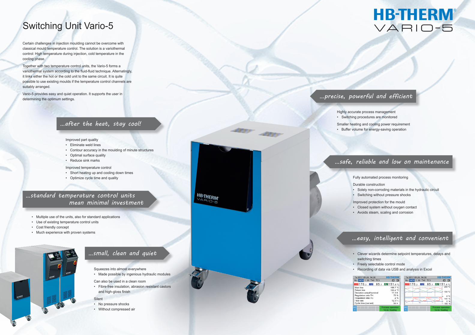
Switching Unit Vario-5Certain challenges in injection moulding cannot be overcome with classical mould temperature control. The solution is a variothermal control: High temperature during injection, cold temperature in the cooling phase.
Together with two temperature control units, the Vario-5 forms a variothermal system according to the fluid-fluid technique. Alternatingly, it links either the hot or the cold unit to the same circuit. It is quite possible to use existing moulds if the temperature control channels are suitably arranged.
Vario-5 provides easy and quiet operation. It supports the user in determining the optimum settings.
…standard temperature control units mean minimal investment
• Multiple use of the units, also for standard applications • Use of existing temperature control units • Cost friendly concept • Much experience with proven systems
…safe, reliable and low on maintenance Fully automated process monitoring
Durable construction • Solely non-corroding materials in the hydraulic circuit • Switching without pressure shocks
Improved protection for the mould • Closed system without oxygen contact • Avoids steam, scaling and corrosion
…easy, intelligent and convenient
• Clever wizards determine setpoint temperatures, delays and switching times • Freely selectable control mode • Recording of data via USB and analysis in Excel
…after the heat, stay cool!
Improved part quality • Eliminate weld lines • Contour accuracy in the moulding of minute structures • Optimal surface quality • Reduce sink marks
Improved temperature control • Short heating up and cooling down times • Optimize cycle time and quality
…small, clean and quiet
Squeezes into almost everywhere • Made possible by ingenious hydraulic modules
Can also be used in a clean room • Fibre-free insulation, abrasion resistant castors andhigh-glossfinish
Silent • No pressure shocks • Without compressed air
…precise, powerful and efficient
Highly accurate process management • Switching procedures are monitored
Smaller heating and cooling power requirement • Buffer volume for energy-saving operation
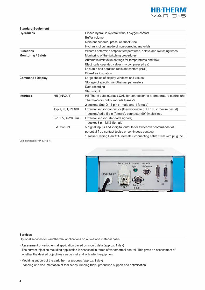
Power supply
Ext. Control Status light
Typ J, K, TPt 100
0–10 V4–20 mA
IN OUTHB
Standard EquipmentHydraulics
Functions Monitoring / Safety
Command / Display
Interface HB (IN/OUT)
Typ J, K, T, Pt 100 0–10 V, 4–20 mA
Ext. Control
Communication (gP. 6, Fig. 1)
ServicesOptional services for variothermal applications on a time and material basis:
• Assessment of variothermal application based on mould data (approx. 1 day) The current injection moulding application is assessed in terms of variothermal control. This gives an assessment of whether the desired objectives can be met and with which equipment.
• Moulding support of the variothermal process (approx. 1 day) Planning and documentation of trial series, running trials, production support and optimisation
4
Closed hydraulic system without oxygen contact Buffer volumeMaintenance-free, pressure shock-freeHydraulic circuit made of non-corroding materialsWizards determine setpoint temperatures, delays and switching timesMonitoring of the switching proceduresAutomatic limit value settings for temperatures and flow Electrically operated valves (no compressed air)Lockable and abrasion resistant castors (PUR)Fibre-free insulationLarge choice of display windows and valuesStorage of specific variothermal parametersData recording Status lightHB-Therm data interface CAN for connection to a temperature control unit Thermo-5 or control module Panel-52 sockets Sub-D 15 pin (1 male and 1 female)External sensor connector (thermocouple or Pt 100 in 3-wire circuit)1 socket Audio 5 pin (female), connector 90° (male) incl.External sensor (standard signals)1 socket 8 pin M12 (female)5 digital inputs and 2 digital outputs for switchover commands via potential-free contact (pulse or continuous contact)1 socket Harting Han 12Q (female), connecting cable 10 m with plug incl.
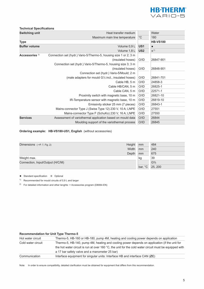
Technical SpecificationsSwitching unit
TypeBuffer volume
Accessories 2)
Services
Ordering example: HB-VS180-US1, English (without accessories)
Dimensions (gP. 7, Fig. 2)
Weight max. Connection, Input/Output (H/C/M)
• Standard specification ° Optional1) Recommended for mould circuits of 0,9 L and larger 2) For detailed information and other lenghts g Accessories program (D8064-EN)
Recommendation for Unit Type Thermo-5Hot water circuit Thermo-5, HB-160 or HB-180, pump 4M, heating and cooling power depends on applicationCold water circuit Thermo-5, HB-140, pump 4M, heating and cooling power depends on application (if the unit for the hot water circuit is run at over 160 °C, the unit for the cold water circuit must be equipped with a 17 bar safety valve and a manometer 25 bar)Communication Interface equipment for singular units: Interface HB and interface CAN (ZC)
Note: In order to ensure compatibility, detailed clarification must be obtained for equipment that differs from this recommendation.
5
Heat transfer medium Maximum main line temperature
Volume 0,9 LVolume 1,8 L
Connection set (hydr.) Vario-5/Thermo-5, housing size 1 or 2; 3 m (insulated hoses)
Connection set (hydr.) Vario-5/Thermo-5, housing size 3; 3 m (insulated hoses)
Connection set (hydr.) Vario-5/Mould; 2 m (male adapters for mould G½ incl., insulated hoses)
Cable HB, 5 m Cable HB/CAN, 5 m Cable CAN, 5 m Proximity switch with magnetic base, 10 m IR-Temperature sensor with magnetic base, 10 m
Emissivity sticker 25 mm (7 pieces) Mains-connector Type J (Swiss Type 12) 230 V, 10 A; LNPE Mains-connector Type F (SchuKo) 230 V, 16 A; LNPE
Assessment of variothermal application based on mould dataMoulding support of the variothermal process
HeightWidthDepth
Water°C 180 HB-VS180US1 • US2 °1)
O/ID 26847-901
O/ID 26848-901
O/ID 26841-701O/ID 24858-3O/ID 26825-1O/ID 22571-1O/ID 26821-10O/ID 26819-10O/ID 26843-1O/ID 27551O/ID 27550O/ID 26844O/ID 26845
mm 484mm 240mm 675kg 39 G¾bar, °C 25, 200
SD
SD
SD
HB
ECMC
MG FMHB HB
HB
VSEG_FB
EG_FB
HB HB/CAN
CAN
CAN
EG1)
EG1)
FMHB
FMHB
OPC UA
OPC UA
HBVS
HB/CANEG
1)
SDEC
MC
EG
HB/CAN
CAN
EG1)
EG1)
VSHB
ECMC
FB
SD
HBMG MG
HBVSFB
HB
SDEC
MC
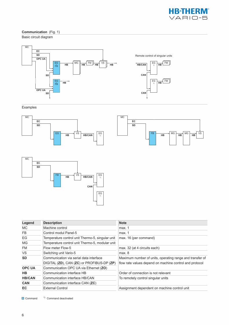
Communication (Fig. 1)Basic circuit diagram
Examples
Legend Description MC Machine controlFB Control modul Panel-5 EG Temperature control unit Thermo-5, singular unitMG Temperature control unit Thermo-5, modular unit FM Flow meter Flow-5VS Switching unit Vario-5SD Communication via serial data interface DIGITAL (ZD), CAN (ZC) or PROFIBUS-DP (ZP)OPC UA Communication OPC UA via Ethernet (ZO) HB Communication interface HBHB/CAN Communication interface HB/CAN CAN Communication interface CAN (ZC) EC External Control
Command 1) Command deactivated
Remote control of singular units
6
Notemax. 1max. 1max. 16 (per command)
max. 32 (at 4 circuits each)max. 8Maximum number of units, operating range and transfer of flow rate values depend on machine control and protocol
Order of connection is not relevantTo remotely control singular units
Assignment dependent on machine control unit
OUT COUT H
IN CIN H
OUT M
IN M
191
19
675
199384
240
179
81
295
259
484
69
270 360
3314
0 51 108
145
182
24
246
Ø 75 Ø 50
434
391
336
279
161
0
General Technical DataPower supply
Environment
Colour
Protection classStandards
Certification/ApprovalTemperature measurement
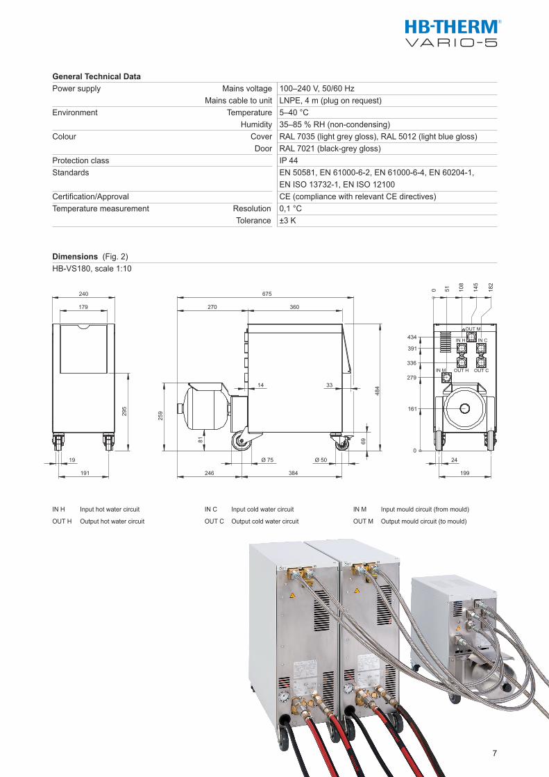
Dimensions (Fig. 2)HB-VS180, scale 1:10
IN H Input hot water circuit IN C Input cold water circuit IN M Input mould circuit (from mould)
OUT H Output hot water circuit OUT C Output cold water circuit OUT M Output mould circuit (to mould)
7
Mains voltage 100–240 V, 50/60 Hz Mains cable to unit LNPE, 4 m (plug on request) Temperature 5–40 °C Humidity 35–85 % RH (non-condensing) Cover RAL 7035 (light grey gloss), RAL 5012 (light blue gloss) Door RAL 7021 (black-grey gloss) IP 44 EN 50581, EN 61000-6-2, EN 61000-6-4, EN 60204-1, EN ISO 13732-1, EN ISO 12100 CE (compliance with relevant CE directives) Resolution 0,1 °C Tolerance ±3 K
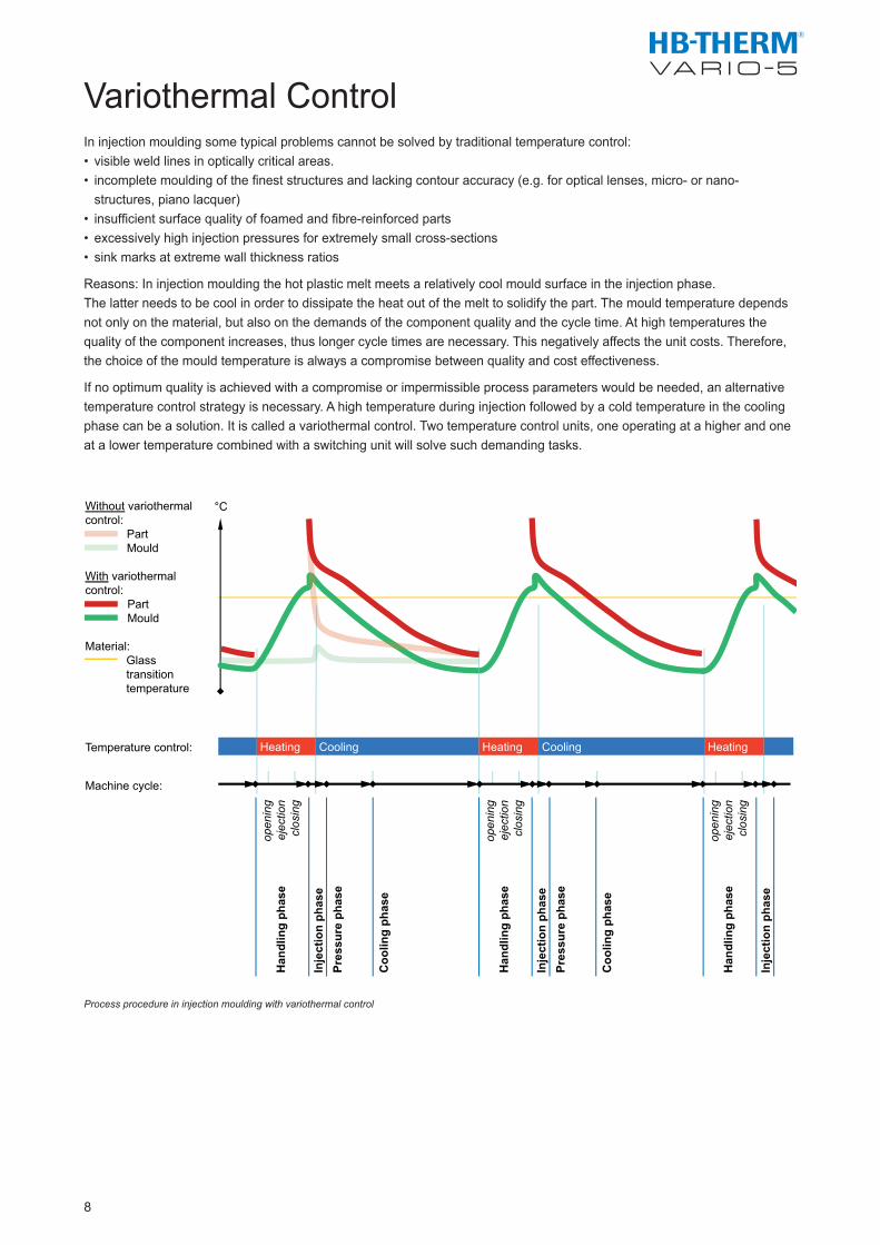
Without variothermal control: Part
Mould With variothermal control: Part Mould Material:
Glass transition temperature
Temperature control:
Machine cycle:
open
ing
ejec
tion
clos
ing
Han
dlin
g ph
ase
Inje
ctio
n ph
ase
Pres
sure
pha
se
Coo
ling
phas
e
open
ing
ejec
tion
clos
ing
Han
dlin
g ph
ase
Inje
ctio
n ph
ase
Pres
sure
pha
se
Coo
ling
phas
e
open
ing
ejec
tion
clos
ing
Han
dlin
g ph
ase
Inje
ctio
n ph
ase
°C
Heating Cooling Heating Cooling Heating
In injection moulding some typical problems cannot be solved by traditional temperature control:• visible weld lines in optically critical areas.• incompletemouldingofthefineststructuresandlackingcontouraccuracy(e.g.foropticallenses,micro-ornano- structures,pianolacquer)• insufficientsurfacequalityoffoamedandfibre-reinforcedparts• excessivelyhighinjectionpressuresforextremelysmallcross-sections• sinkmarksatextremewallthicknessratios
Reasons: In injection moulding the hot plastic melt meets a relatively cool mould surface in the injection phase. The latter needs to be cool in order to dissipate the heat out of the melt to solidify the part. The mould temperature depends notonlyonthematerial,butalsoonthedemandsofthecomponentqualityandthecycletime.Athightemperaturesthequalityofthecomponentincreases,thuslongercycletimesarenecessary.Thisnegativelyaffectstheunitcosts.Therefore,thechoiceofthemouldtemperatureisalwaysacompromisebetweenqualityandcosteffectiveness.
Ifnooptimumqualityisachievedwithacompromiseorimpermissibleprocessparameterswouldbeneeded,analternativetemperaturecontrolstrategyisnecessary.Ahightemperatureduringinjectionfollowedbyacoldtemperatureinthecoolingphasecanbeasolution.Itiscalledavariothermalcontrol.Twotemperaturecontrolunits,oneoperatingatahigherandoneatalowertemperaturecombinedwithaswitchingunitwillsolvesuchdemandingtasks.
Process procedure in injection moulding with variothermal control
8
Variothermal Control
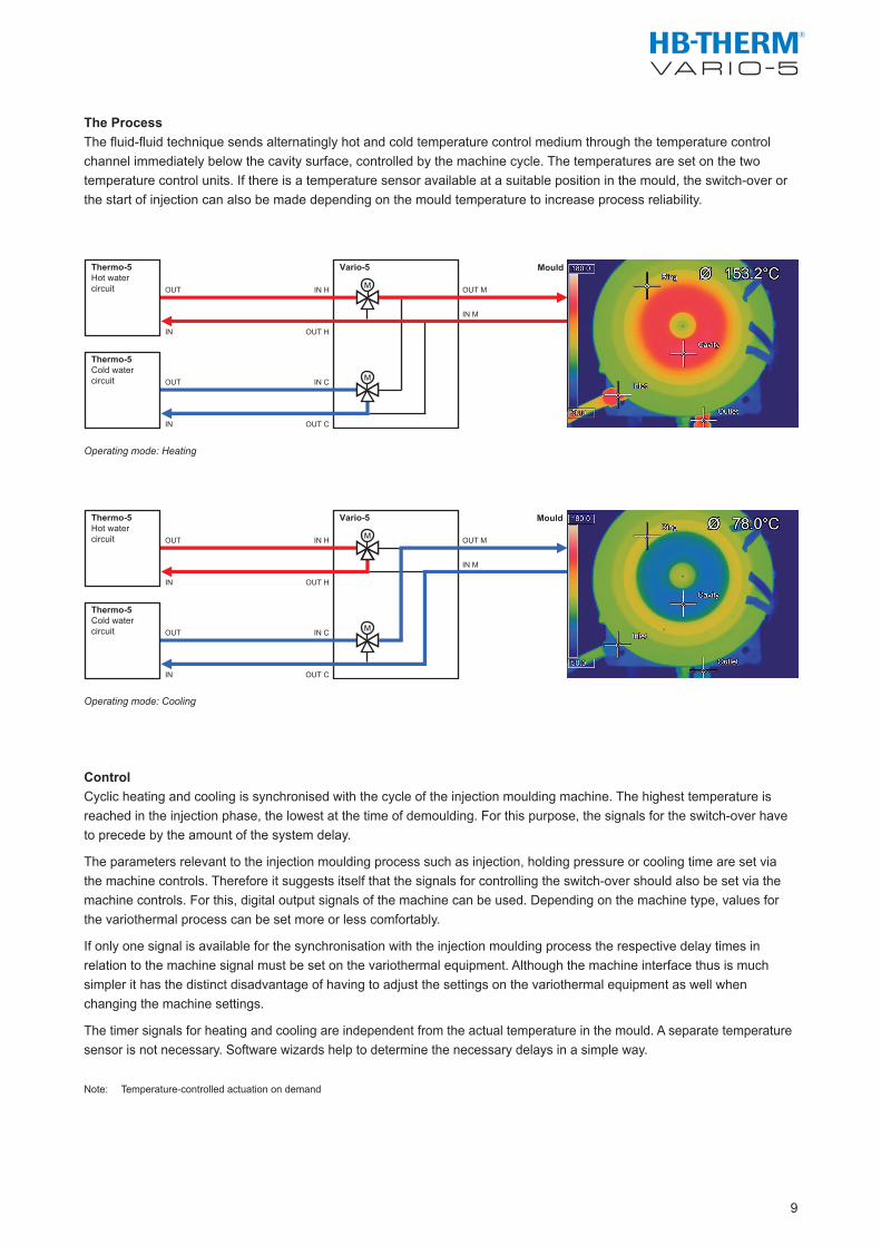
Thermo-5 Hot water circuit
Thermo-5 Cold water circuit
Mould
M
OUT IN C
IN OUT C
M
OUT IN H
IN OUT H
OUT M
IN M
Vario-5
Thermo-5 Hot water circuit
Thermo-5 Cold water circuit
Mould Vario-5
M
OUT IN C
IN OUT C
M
OUT IN H
IN OUT H
OUT M
IN M
The ProcessThe fluid-fluid technique sends alternatingly hot and cold temperature control medium through the temperature control channel immediately below the cavity surface, controlled by the machine cycle. The temperatures are set on the two temperature control units. If there is a temperature sensor available at a suitable position in the mould, the switch-over or the start of injection can also be made depending on the mould temperature to increase process reliability.
Operating mode: Heating
Operating mode: Cooling
ControlCyclic heating and cooling is synchronised with the cycle of the injection moulding machine. The highest temperature is reached in the injection phase, the lowest at the time of demoulding. For this purpose, the signals for the switch-over have to precede by the amount of the system delay.
The parameters relevant to the injection moulding process such as injection, holding pressure or cooling time are set via the machine controls. Therefore it suggests itself that the signals for controlling the switch-over should also be set via the machine controls. For this, digital output signals of the machine can be used. Depending on the machine type, values for the variothermal process can be set more or less comfortably.
If only one signal is available for the synchronisation with the injection moulding process the respective delay times in relation to the machine signal must be set on the variothermal equipment. Although the machine interface thus is much simpler it has the distinct disadvantage of having to adjust the settings on the variothermal equipment as well when changing the machine settings.
The timer signals for heating and cooling are independent from the actual temperature in the mould. A separate temperature sensor is not necessary. Software wizards help to determine the necessary delays in a simple way.
Note: Temperature-controlled actuation on demand
9
Frame ConditionsIn variothermal control the temperature at the surface of the cavity will be actively changed within the injection cycle. The area around the cavity is thus cyclically heated and cooled. Depending on the configuration of the temperature control channels the temperature at the surface of the cavity reacts stronger or weaker and the area is larger or smaller.
To efficiently achieve the largest temperature gradients possible the following is recommended:
Distance of the temperature controlchannel from the surface of the cavity Variothermal mass
Isolation
Connections
Material
Temperature control channel crosssectionFlow rate
Note: Variothermally controlled circuits can come up to the temperature of the hot unit. Seals, couplings, hoses need to be selected accordingly. The cyclical temperature changes can cause moveable inserts such as sliders to jam.
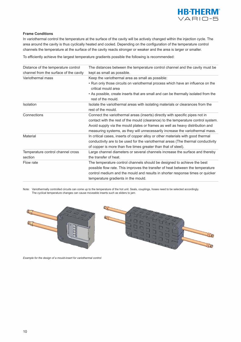
Example for the design of a mould-insert for variothermal control
10
The distances between the temperature control channel and the cavity must be kept as small as possible.Keep the variothermal area as small as possible:• Run only those circuits on variothermal process which have an influence on the critical mould area• As possible, create inserts that are small and can be thermally isolated from the rest of the mould. Isolate the variothermal areas with isolating materials or clearances from the rest of the mould.Connect the variothermal areas (inserts) directly with specific pipes not in contact with the rest of the mould (clearance) to the temperature control system. Avoid supply via the mould plates or frames as well as heavy distribution and measuring systems, as they will unnecessarily increase the variothermal mass.In critical cases, inserts of copper alloy or other materials with good thermal conductivity are to be used for the variothermal areas (The thermal conductivity of copper is more than five times greater than that of steel).Large channel diameters or several channels increase the surface and thereby the transfer of heat.The temperature control channels should be designed to achieve the best possible flow rate. This improves the transfer of heat between the temperature control medium and the mould and results in shorter response times or quicker temperature gradients in the mould.

Temperature Control Technology
11
HB-Therm worldwide.HB-Therm is one of the leading manufacturers of temperature control units worldwide. Since 1967 HB-Therm AG has been developing and producing innovative temperature control technology to the highest quality standards. With its comprehensive know-how and motivated workforce, the company has succeeded in becoming the technology leader in its sector.
This Swiss family enterprise employs around 130 staff and has established itself as a systems supplier offering seamless customer support from machine design through to a complete after-sales service. Production is exclusively in St. Gallen. Own subsidiaries (Sales & Service) in Germany and France as well as 40 other national agencies are representing HB-Therm around the globe.
The company‘s quality and environmental management system is based on the continual improvement of all activities and processes and is certified to ISO 9001/14001. All its products and services are based on a philosophy of offering „Swiss-made“ quality to customers.
Customer service. Included.With our sales and marketing network service we can offer comprehensive expert advice and assistance in: • Optimum temperature control process • Determination of the specification of the product and advice regarding functionality • Electrical and hydraulic connections • Data interfaces • Heat transfer medium• Servicing of the equipment
Our experts are always available for support when questions of specialist requirements or applications arise or when putting the equipment into operation, or for the operational training of your staff.
D8108-EN 2017-10 Specifications are subject to change without notice
HB-THERM AGSpinnereistrasse 10 (WU 3)Postfach9006 St. GallenSwitzerlandPhone +41 71 243 6-530, Fax [email protected], www.hb-therm.ch
Subsidiaries
HB-THERM GmbHDammstrasse 70-8053721 Siegburg GermanyPhone +49 2241 5946-0, Fax [email protected], www.hb-therm.de
HB-THERM S.A.S.La Grande Vaupière01390 Saint-Jean-de-ThurigneuxFrancePhone +33 4 74 00 43 30 Fax +33 4 26 23 68 [email protected], www.hb-therm.fr
DistributorsAustralia (AU)Parrington Group Pty. Ltd., Magill SA 5072
Austria (AT)Luger Gesellschaft mbH, 3011 Purkersdorf
Belgium (BE)AJ Solutions BVBA, 2240 Zandhoven
Brazil (BR)HDB Representações Ltda, Cotia (SP) 06705-110
China (CN)ARBURG (Shanghai) Co., Ltd., 201100 ShanghaiARBURG Machine & Trading, 518108 ShenzhenDongguan Cenglary Trading Co., Ltd., 523850 Dongguan CityTianjin Cenglary Trading Co., Ltd., 300452 Tianjin CityJiangsu Cenglary Engineering & Trading Co., Ltd.,215300 Kunshan Devel. Dist.
Croatia (HR)Luger Gesellschaft mbH, 3011 Purkersdorf
Czech Republic (CZ)Luger spol. s.r.o., 251 01 Ricany
Denmark (DK)SAXE Hansen, 3500 Værløse
Estonia (EE)Telko Estonia OU, 13522 Tallinn
Finland (FI)Engel Finland Oy, 00380 Helsinki
France (FR)HB-THERM S.A.S., 01390 Saint-Jean-de-Thurigneux
Germany (DE)HB-THERM GmbH, 53721 Siegburg
Hong Kong (HK)ARBURG (HK) Ltd., Quarry Bay
Hungary (HU)Luger Kft., Budapest 1147
India (IN)Salnik Solutions, 400072 Mumbai
Indonesia (ID)ARBURG Indonesia, Jakarta 10150
Ireland (IE)KraussMaffei (UK) Ldt, WA5 7TR Warrington
Israel (IL)SU-PAD Ltd., 4809102 Rosh Ha‘ayn
Italy (IT) Nickerson Italia Srl, 24030 Brembate di Sopra (BG)
Japan (JP)ARBTECHNO Ltd., Iwaki 973-8406
Korea, Republic of (KR)IMTS, 158-879 Seoul
Latvia (LV)Telko Lativia SIA, 1026 Riga
Liechtenstein (LI)HB-THERM AG, 9006 St. Gallen
Lithuania (LT)Telko Lietuva UAB, 51183 Kaunas
Luxembourg (LU)AJ Solutions BVBA, 2240 Zandhoven
Malaysia (MY)ARBURG Sdn Bhd, 46150 Petaling Jaya
Mexico (MX)Engel Mexico S.A. de C.V., 76246 El Marques, Querétaro
Netherlands (NL)ROBOTECH bv, 4824 AS Breda
New Zealand (NZ)AOTEA MACHINERY LTD., Auckland 1145
Poland (PL)ELBI-Wrocław Sp. z o.o., 53-234 Wrocław
Portugal (PT)Netstal Máquinas, S.A., 08100 Mollet del Vallès
Romania (RO) Plastic Technology Service Srl, 032451 Bucuresti
Singapore (SG)ARBURG PTE LTD., Singapore 139965
Slovakia (SK)Luger spol. s.r.o., 251 01 Ricany
Slovenia (SI)Luger Gesellschaft mbH, 3011 Purkersdorf
South Africa (ZA)GREEN TECH Machinery Ltd, 1709 Quellerina
Spain (ES)Netstal Máquinas, S.A., 08100 Mollet del Vallès
Sweden (SE)Forvema AB, 511 54 Kinna
Switzerland (CH)HB-THERM AG, 9006 St. Gallen
Taiwan (TW)Morglory International Co., Ltd., Taichung City 40757
Thailand (TH)ARBURG (Thailand) Co., Ltd., Samutprakarn 10540
Turkey (TR)ARBURG Plastik Enjeksiyon, 34524 Yakuplu-Büyükçekmece/Istanbul
United Kingdom (GB)KraussMaffei (UK) Ldt, WA5 7TR Warrington
United States (US)Frigel North America, East Dundee, IL 60118