Embed Size (px)
Citation preview

Switching of perpendicularly polarized nanomagnetswith spin orbit torque without an external magneticfield by engineering a tilted anisotropyLong Youa, OukJae Leea, Debanjan Bhowmika, Dominic Labanowskia, Jeongmin Honga, Jeffrey Bokora,and Sayeef Salahuddina,b,1
aDepartment of Electrical Engineering and Computer Sciences, University of California, Berkeley, CA 94720; and bMaterials Sciences Division, LawrenceBerkeley National Laboratory, Berkeley, CA 94720
Edited by Jian-Ping Wang, University of Minnesota, Minneapolis, MN, and accepted by the Editorial Board July 4, 2015 (received for review April 21, 2015)
Spin orbit torque (SOT) provides an efficient way to significantlyreduce the current required for switching nanomagnets. However,SOT generated by an in-plane current cannot deterministically switcha perpendicularly polarized magnet due to symmetry reasons. On theother hand, perpendicularly polarized magnets are preferred over in-plane magnets for high-density data storage applications due to theirsignificantly larger thermal stability in ultrascaled dimensions. Here,we show that it is possible to switch a perpendicularly polarizedmagnet by SOT without needing an external magnetic field. This isaccomplished by engineering an anisotropy in the magnets such thatthe magnetic easy axis slightly tilts away from the direction, normalto the film plane. Such a tilted anisotropy breaks the symmetry of theproblem andmakes it possible to switch themagnet deterministically.Using a simple Ta/CoFeB/MgO/Ta heterostructure, we demonstratereversible switching of the magnetization by reversing the polarityof the applied current. This demonstration presents a previouslyunidentified approach for controlling nanomagnets with SOT.
spin orbit torque | perpendicular anisotropy | nanomagnets
Spin orbit coupling (SOC) and/or broken inversion symmetry invertical heterostructures can generate accumulation of spins
when a charge current is flowing through them. In doing so, it canexert a torque on an adjacent magnet (1–8). Indeed, high Z metals(Ta, Pt, W, etc.) with strong SOC have been used to inject spincurrents into adjacent ferromagnetic layers and thereby to inducemagnetic switching, oscillation, domain wall movement, etc. (1–5, 7–9).In a typical heterostructure such as Ta/CoFeB/MgO (from thebottom), an in-plane current flowing in the x direction (electronsflowing in the –x direction) generates σ= y polarized spins thataccumulate at the Ta/CoFeB interface. Therefore, if the ferro-magnet (CoFeB) is polarized in-plane, the spin accumulation canrotate it to the +y direction by a Slonczewski-like torque~τsl = τ0sl(m× σ × m) (10). The magnet can be switched to –y direction byreversing the polarity of the current. Thus, a deterministicswitching is possible by an in-plane current when the magnet isalso polarized in-plane. However, if the magnet has a perpen-dicular magnetic anisotropy (PMA), an in-plane current andresultant in-plane spin accumulation cannot break the reversalsymmetry. Consequently, no deterministic switching of the PMAmagnet can be obtained. For this reason, an external magneticfield has to be applied in-plane in the same (or opposite) di-rection of the current flow that breaks the symmetry and makes itpossible to switch a PMA magnet with an in-plane current (11).It is, however, desirable to switch the magnetization withoutneeding an external magnetic field. At the same time, PMA ismore suitable for scaling magnets to ultrasmall dimensions whileretaining reasonable thermal stability (12–14). This means thatalternate ways need to be found that can lead to symmetrybreaking and make it possible to switch perpendicularly polar-ized magnets with in-plane current without having to apply anexternal magnetic field. In this paper, we report on such ascheme where we have fabricated magnetic nanodots from a
heterostructure stack of Ta/CoFeB/MgO such that their easyaxes are slightly tilted from the film normal. This tilting breaksthe symmetry with respect to an in-plane spin orbit torque(SOT). Indeed, pulsed currents flowing in-plane deterministicallyswitch the magnetization up and down without any external mag-netic fields. Notably, in a recent experimental work, Yu et al. (15)have shown that an in-plane current can switch perpendicularlypolarized magnet by creating a thickness gradient in the film overthe entire substrate. They showed that the structural symmetrybreaking thus generated leads to a vertically oriented Rashba fieldthat in turn switches the magnet. The physics of switching in ourwork, by contrast, is completely different. It is rather the non-conservative Slonczewski torque that is responsible for switching inour scheme and no distinguishable vertical Rashba field could bemeasured in our devices (as we discuss in details later).The essential idea is described in Fig. 1. Imagine a magnet that
has an easy axis on the x–z plane but slightly tilted away from thez axis to x axis as shown in Fig. 1A. Here, x–y is the film plane.The actual device is made of a heterostructure consisting of Ta/CoFeB/MgO as shown in Fig. 1B. For brevity, when the magnetis in the (x, z) quadrature, we shall call it the “up” position.Similarly when it is in the (−x, −z) quadrature, we shall call it the“down” position. Now imagine a current is applied in the x di-rection such that a y polarized spin accumulation is generatedat the Ta/CoFeB interface. Because y is orthogonal to the x–zplane, regardless of whether or not there is a tilt in the easy axisof the magnet in the x–z plane, no symmetry is broken and
Significance
When a spin orbit torque is applied to a magnet with perpen-dicular anisotropy, the induced spin accumulation is completelysymmetric with respect to the magnetization. As a result, a de-terministic switching cannot be achieved unless an externalmagnetic field is applied to break the symmetry. Here, we showthat, by engineering a tilted anisotropy in a magnetic nanodot,the symmetry can effectively be broken and a deterministicswitching of perpendicular magnetization can be achieved with-out needing the external magnetic field. These results are sig-nificant for the field of spintronics as the symmetry breakingprovides new insight into the physics of spin orbit torque and theswitchingwithout amagnetic field could lead to significant impactin high-density storage applications.
Author contributions: L.Y., O.L., and S.S. designed research; L.Y., O.L., D.B., D.L., J.H., andS.S. performed research; L.Y., D.L., J.B., and S.S. analyzed data; and L.Y., O.L., D.B., D.L.,and S.S. wrote the paper.
The authors declare no conflict of interest.
This article is a PNAS Direct Submission. J.-P.W. is a guest editor invited by the EditorialBoard.1To whom correspondence should be addressed. Email: [email protected].
This article contains supporting information online at www.pnas.org/lookup/suppl/doi:10.1073/pnas.1507474112/-/DCSupplemental.
10310–10315 | PNAS | August 18, 2015 | vol. 112 | no. 33 www.pnas.org/cgi/doi/10.1073/pnas.1507474112
therefore the magnetization cannot be switched deterministi-cally. However, this situation changes if a current is applied inthe y or −y direction. This will generate a spin accumulationpolarized in the –x or +x direction, respectively (for Ta). If themagnetization is in the x–z plane and tilted from the z axis, thedirection of spin polarization (x or −x) is no longer symmetricwith respect to the tilted easy axis of the magnet and this sym-metry breaking can lead to deterministic reversal of the mag-netization (16). For example, let us consider the situation whenthe magnet is polarized up and a current is flowing in the ydirection leading to a spin polarization in the –x direction. If thisaccumulation is strong enough to rotate the magnetization to the–x direction, in the process, the magnet would cross over thehard axis, shown by the dotted line in Fig. 1A. This means thatwhen the current is turned off, it is preferable for the magnet tonow go to the down position in the (−x, −z) quadrature. On theother hand, if a current is applied in the –y direction, the spin
accumulation is +x polarized. This means starting from up, themagnet, in the process of rotating to +x direction, does not crossover the hard axis. Thus, when the current is turned off, it ispreferable for the magnet to go back to the up state. Thus, acurrent along +y switches the magnet from up to down. Similarly,a current along –y will switch the magnet from down to up. Whenthe magnet is up, a current along –y does not change the state ofthe magnet. Similarly, when the magnet is down, a current along+y cannot change the state of the magnet. Thus, a fully deter-ministic switching of the perpendicular magnetization can beachieved without an external magnetic field.Our fabricated devices are based on a stack consisting of
Ta (10 nm)/CoFeB (1 nm)/MgO (1 nm)/Ta (∼3 nm) (from thebottom). Vibrating sample magnetometer measurement showsexcellent perpendicular anisotropy in the thin films (SI Appendix,section 1). First, small nanomagnets are patterned with a highaspect ratio (50 × 300 nm). Next, a wedge shape was created by
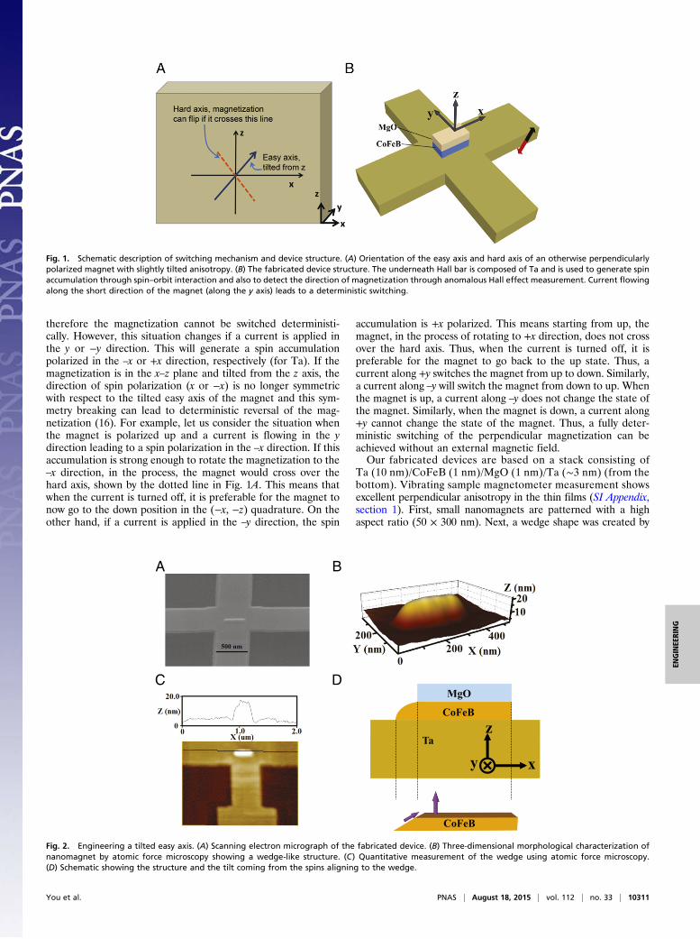
Fig. 1. Schematic description of switching mechanism and device structure. (A) Orientation of the easy axis and hard axis of an otherwise perpendicularlypolarized magnet with slightly tilted anisotropy. (B) The fabricated device structure. The underneath Hall bar is composed of Ta and is used to generate spinaccumulation through spin–orbit interaction and also to detect the direction of magnetization through anomalous Hall effect measurement. Current flowingalong the short direction of the magnet (along the y axis) leads to a deterministic switching.
A
MgO
y Ta
z CoFeB
x
CoFeB
B
C D
Fig. 2. Engineering a tilted easy axis. (A) Scanning electron micrograph of the fabricated device. (B) Three-dimensional morphological characterization ofnanomagnet by atomic force microscopy showing a wedge-like structure. (C) Quantitative measurement of the wedge using atomic force microscopy.(D) Schematic showing the structure and the tilt coming from the spins aligning to the wedge.
You et al. PNAS | August 18, 2015 | vol. 112 | no. 33 | 10311
ENGINEE
RING

carefully controlling the thickness of the hard mask and Ar+
ion milling such that the thickness of the magnet gradually goesto zero on one side (details are described in Methods andSI Appendix, Fig. S2). Fig. 2A shows an SEM micrograph of atypical nanodot and the underneath Hall structure for trans-port measurement. Fig. 2B shows an atomic force microscopyimage of the nanodot. A wedge-like feature is clearly seen.The depth profile shown in Fig. 2C indicates that MgO withlateral size of around 50 nm in the left part of nanomagnet wascompletely etched, and CoFeB wedge was created. BecauseMgO was etched out, the magnetization in the wedge regionno longer has a perpendicular anisotropy and will follow theedge of the wedge to minimize magnetostatic energy, therebyproviding an overall tilt to the perpendicular magnet, di-rected away from the edge (17–20). Micromagnetic simula-tions (SI Appendix, section 2) confirm that this indeed is thecase, as we will discuss later.We have performed anisotropic magnetoresistance (AMR)
measurements to investigate potential tilting of the easy axis.Note that all of the experiments in this work were done at theambient temperature. In the coordinate axes as shown in Fig.3 A and B, the dependence of resistivity on the rotation angleθ of the in-plane magnetic field (Hinp), as obtained from theAMR measurement, can be written as follows:
ρðθÞ= ρ⊥ +�ρ== − ρ⊥
�cos2ϕðθÞ= ρ⊥ +Δρcos2ϕðθÞ, [1]
where φ is the angle between the magnetization M and the di-rection of current and (ρ==) is the resistivity when the magneti-zation is perpendicular (parallel) to the current direction. Let usconsider the case when current is flowing in the −x direction anda Hinp of a specific amplitude is rotated in-plane, starting fromthe –x axis and ending on the +x axis. Because the current isapplied along the x axis, from Eq. 1, the resistance is themaximum when the Hinp is also along the ±x direction. Resis-tance is lower when Hinp is rotated away from x axis. Notably, ifthe magnetic easy axis is purely out-of-plane to begin with, ap-plying the same magnitude of Hinp in the +x or –x directionshould give the same resistance value. By contrast, if the magnetis tilted on the +x axis, one would expect to see a larger resis-tance when the Hinp is in the +x direction in comparison withwhen the field is in the –x direction. This is exactly what weobserve in our experiments. Starting from an initially up position,the resistance is larger when Hinp is in the +x direction comparedwith when it is in the direction and the resistance goes downaway from the x axis (Fig. 3C). On the other hand, starting froman initial down position, the resistance is larger when Hinp is inthe −x direction (Fig. 3D). This asymmetric resistance curve isalso observed when magnetic fields of other magnitudes are ap-plied such as 500, 800, 2,000 Oe, etc. (See SI Appendix, section 3,for details.) These data show that the easy axis of the magneti-zation is slightly tilted from the z axis and lies along (x, z)quadrature to (−x, −z) quadrature. The observed behavior canbe modeled well from Eq. 1 including the fact that the lowestvalue of resistance arises slightly away from the y axis and thesign of the shift depends on the starting polarization of the mag-net, i.e., up or down. Finally, we have done AMR measurementswith large Hinp (∼3,000 Oe). Fig. 3 E and F show AMR data atthis field starting from up and down positions, respectively. Noasymmetry is observed between the AMR recorded for Hinp ap-plied in the +x and –x direction. This is expected because nowHinp is strong enough to overcome the tilted anisotropy and themagnet follows the magnetic field. Thus, from the symmetricAMR along the x axis at high field and asymmetric AMR atlow field, the existence of a tilted easy axis in the nanodots isconfirmed. From the sign of the asymmetry, when the CoFeBwedge is in –x as shown in Fig. 2C, one can also conclude that theeasy axis lies on the x–z plane, slightly tilted toward x from z, asshown in Fig. 1A. By AMR measurement, we can also estimatethe angle of the tilt, which comes to be ∼2° with an error of 1°due to the uncertainty in the angle of the in-plane field. At thesame time, from comparing the slant in the R-H loop of an anom-alous Hall resistance measurement for the wedged dot to a circulardot, another estimate for the tilt amplitude can be made. This mea-surement gives the tilt angle to be ∼5° (SI Appendix, section 5).Based on these two measurements, we estimate the tilt angle tobe between 2° and 5°.With such a tilted easy axis of the nanodots, the switching sce-
nario described in the preceding paragraphs, namely a deterministicswitching from up to down with a current in the y direction andfrom down to up with a current in the –y direction, should bepossible. To demonstrate that we have performed anomalous Halleffect (AHE) measurements. The corresponding hysteresis loop isshown in Fig. 4A. Fig. 4B shows switching data at room temperaturein the presence of zero external field. The magnet is saturated todown first by applying a strong vertical magnetic field in –z direction.Next, the field is turned off and a current pulse (∼1-s duration) of1.25 mA (2.5 × 10⁷ A/cm2) is applied in the –y direction. After thepulse is off, an AHE measurement is done by applying a small sensecurrent. The AHE resistance, as shown in the bottom panel ofFig. 4B, shows that the magnet is now up. Next, a current pulse of the
Fig. 3. Estimation of the tilt direction. The schematic configuration of the co-ordinate system used in the analysis of the AMR data. A and B show the con-figurations for the initial polarization of up and down, respectively. The sensecurrent for AHE measurement flows along −x direction pointing to the long axisof the nanomagnet. θ is the angle between the directions of the measurementcurrent and the external in-plane field Hinp. θ = 0 corresponds to the orientationwhere the applied field is aligned to the direction of current flow. θ was taken aspositive for an anticlockwise rotation of the field from current. φ is the anglebetween M and I. Calculated and measured values of AMR resistivity are shownwhen jHinpj = 1,000 Oe and the magnet was initially polarized (C) upward and(D) downward. Calculated and measured values of AMR resistivity are shownwhen jHinpj = 3,000 Oe, and the magnet was initially polarized (E) upward and(F) downward.
10312 | www.pnas.org/cgi/doi/10.1073/pnas.1507474112 You et al.
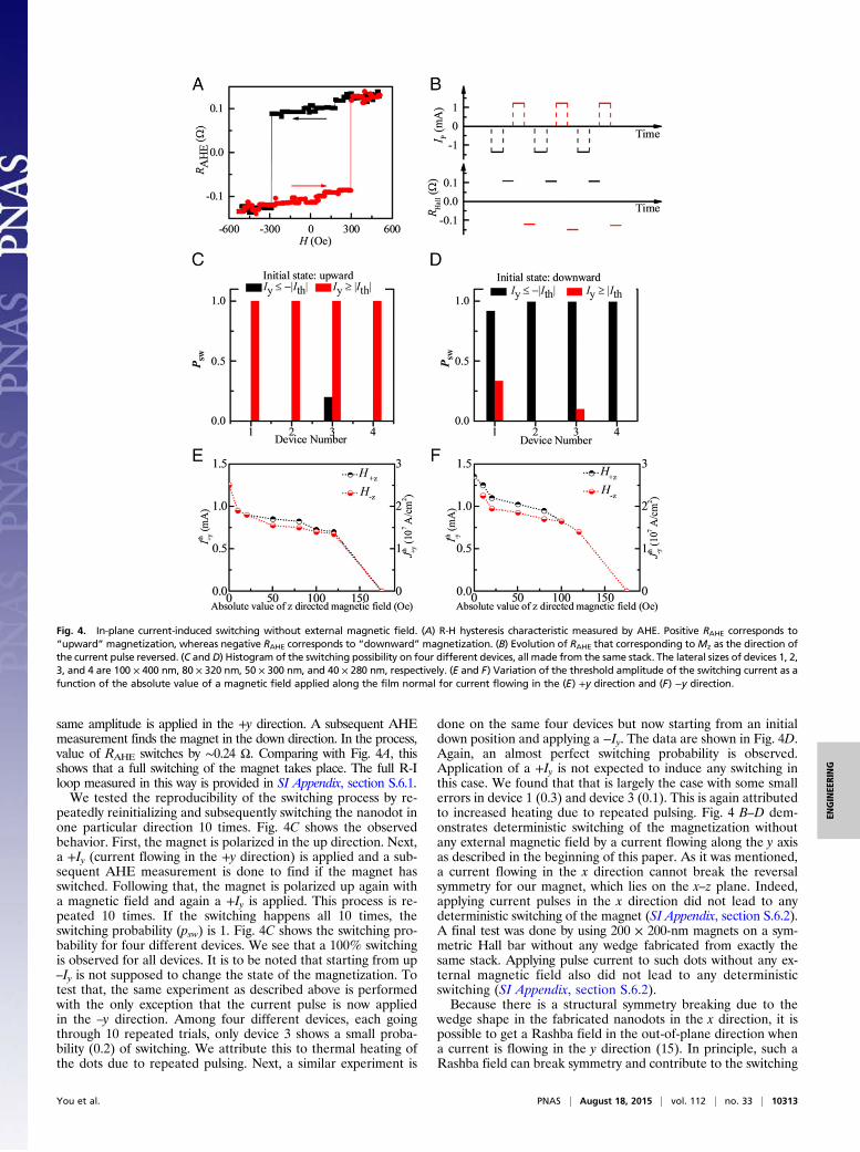
same amplitude is applied in the +y direction. A subsequent AHEmeasurement finds the magnet in the down direction. In the process,value of RAHE switches by ∼0.24 Ω. Comparing with Fig. 4A, thisshows that a full switching of the magnet takes place. The full R-Iloop measured in this way is provided in SI Appendix, section S.6.1.We tested the reproducibility of the switching process by re-
peatedly reinitializing and subsequently switching the nanodot inone particular direction 10 times. Fig. 4C shows the observedbehavior. First, the magnet is polarized in the up direction. Next,a +Iy (current flowing in the +y direction) is applied and a sub-sequent AHE measurement is done to find if the magnet hasswitched. Following that, the magnet is polarized up again witha magnetic field and again a +Iy is applied. This process is re-peated 10 times. If the switching happens all 10 times, theswitching probability (psw) is 1. Fig. 4C shows the switching pro-bability for four different devices. We see that a 100% switchingis observed for all devices. It is to be noted that starting from up–Iy is not supposed to change the state of the magnetization. Totest that, the same experiment as described above is performedwith the only exception that the current pulse is now appliedin the –y direction. Among four different devices, each goingthrough 10 repeated trials, only device 3 shows a small proba-bility (0.2) of switching. We attribute this to thermal heating ofthe dots due to repeated pulsing. Next, a similar experiment is
done on the same four devices but now starting from an initialdown position and applying a −Iy. The data are shown in Fig. 4D.Again, an almost perfect switching probability is observed.Application of a +Iy is not expected to induce any switching inthis case. We found that that is largely the case with some smallerrors in device 1 (0.3) and device 3 (0.1). This is again attributedto increased heating due to repeated pulsing. Fig. 4 B–D dem-onstrates deterministic switching of the magnetization withoutany external magnetic field by a current flowing along the y axisas described in the beginning of this paper. As it was mentioned,a current flowing in the x direction cannot break the reversalsymmetry for our magnet, which lies on the x–z plane. Indeed,applying current pulses in the x direction did not lead to anydeterministic switching of the magnet (SI Appendix, section S.6.2).A final test was done by using 200 × 200-nm magnets on a sym-metric Hall bar without any wedge fabricated from exactly thesame stack. Applying pulse current to such dots without any ex-ternal magnetic field also did not lead to any deterministicswitching (SI Appendix, section S.6.2).Because there is a structural symmetry breaking due to the
wedge shape in the fabricated nanodots in the x direction, it ispossible to get a Rashba field in the out-of-plane direction whena current is flowing in the y direction (15). In principle, such aRashba field can break symmetry and contribute to the switching
Fig. 4. In-plane current-induced switching without external magnetic field. (A) R-H hysteresis characteristic measured by AHE. Positive RAHE corresponds to“upward” magnetization, whereas negative RAHE corresponds to “downward” magnetization. (B) Evolution of RAHE that corresponding toMz as the direction ofthe current pulse reversed. (C and D) Histogram of the switching possibility on four different devices, all made from the same stack. The lateral sizes of devices 1, 2,3, and 4 are 100 × 400 nm, 80 × 320 nm, 50 × 300 nm, and 40 × 280 nm, respectively. (E and F) Variation of the threshold amplitude of the switching current as afunction of the absolute value of a magnetic field applied along the film normal for current flowing in the (E) +y direction and (F) −y direction.
You et al. PNAS | August 18, 2015 | vol. 112 | no. 33 | 10313
ENGINEE
RING

of the nanodot. Second harmonic measurements in our devicesshow similar values for longitudinal and transverse field com-ponents to those that have been reported for similar structures inliterature (6, 15, 21) (SI Appendix, section 8). To test the exis-tence of an out-of-plane field in our devices, we have measuredthe threshold current needed to switch the magnetization inpresence of an out-of-plane magnetic field. The basic idea is thatif a current-induced Rashba field is present in the out-of-planedirection, the RAHE vs. Hz hysteresis loop will be shifted left orright from its symmetric-around-zero position as shown inFig. 4A. Fig. 4E shows the variation of threshold current flowingin the +y direction (Ithy ) as a function of the absolute value of anapplied field in the z direction. First, note that at zero current theHc and −Hc have the same absolute value, which is 175 Oe (notethat this is a different device than that shown in Fig. 4A). If aRashba field is present, a gap between Hz and –Hz should openup as the amplitude of applied current goes up. Therefore, themost important region to look at will be where the current am-plitude is close to the threshold amplitude needed for zeromagnetic field switching. However, in Fig. 4E, we observe that atthese high current levels there is hardly any difference betweenHz and –Hz. A similar trend is seen when a current is applied inthe –y direction in Fig. 4F. This indicates that the contribution ofan out-of-plane Rashba field, if any, is minimal in our devices.In the intermediate range where neither the applied field nor
the current alone is strong enough to switch the magnet, a gapbetween Hz and –Hz can be observed. Note that, in this in-termediate range, there is significant difficulty in ascertaining theexact value of the threshold current. Essentially, after setting aspecific absolute value of the magnetic field, say 75 Oe, multipleexperiments had to be done by varying the amplitude of the ap-plied current pulse to find the threshold value. These repeatedtrials led to some uncertainty as to the exact value of thethreshold current and also heating of the samples, which canalso influence threshold current nontrivially. We note that, for agiven absolute value of the magnetic field, the difference be-tween the switching currents never exceeded 10% of the appliedpulse amplitude (Fig. 4 E and F). This is well within the exper-imental error in this intermediate region. As either the current orthe field amplitude increases, the switching becomes easier andthe uncertainty in the switching current goes down. In addition, if
one tries to associate a Rashba field for this intermediate region,for +Iy it will be pointing in the –z direction from Fig. 4E.However, for –Iy, it is still in the –z direction (Fig. 4F), althoughreversing the current polarity should have reversed it. Because ofthe aforementioned two reasons, we believe that the gap ob-served between the magnetic field values in the intermediateregion is an experimental artifact.Detailed micromagnetic simulations were performed using the
OOMMF package (22) to elucidate on the underlying physics(see SI Appendix, section 2, for details). A mesh was set up tocapture the wedge in the magnet. With a magnet that closelyfollows the experimental dimensions (total 300 nm in length with60-nm wedge, 90 nm wide, and 1.2 nm thick in the thickest area),the first set of tests were aimed at finding the equilibrium mag-netization of the magnet. Starting from an initial condition ofmostly up (with a slight component in the y direction to initiatethe dynamics), when the magnet was allowed to relax, it went toan up position with a small component along the x direction,which is away from the wedge (Fig. 5A), exactly as it is observedin the experiments. The opposite happens when one starts froman initial condition of mostly down (Fig. 5B). This effect is un-derstandable from magnetostatics. The magnetization in thewedge area has no perpendicular anisotropy because the MgOhas been completely etched off. As a result, they follow the edgeof the wedge such that the surface magnetic charge is minimized.Furthermore, they also try to align with the spins in the per-pendicular region due to exchange coupling. As a result, theypoint in the +x direction when bulk of the magnet is +z and viceversa. What is reassuring is the fact that the overall tilt comes tobe around 3° (SI Appendix, section S.2.2), which is very similar towhat we have measured experimentally. Now starting from aninitial magnetization along the x axis, as it will be when a currentis applied along the y axis, depending on whether it started from+x or –x, the magnetization goes to +z or –z direction after thecurrent is turned off, exactly as we have seen in our experiments(Fig. 5 C and D). Therefore, the simulations clearly show that thepreferred direction of the tilt in our devices comes from mini-mizing the magnetostatic energy in the structure. Starting fromthat tilted position, the final state of the magnetization upon theapplication of current is also correctly predicted by the simula-tions. It also shows that the switching process is likely to be
Fig. 5. Micromagnetic simulation. (A) Starting from the magnet saturated in +z state with a small +y component, the system is allowed to relax. The finalequilibrium state of the magnet is such that the moments in the wedge region point toward +x. Thus, average magnetization tilts toward +x. (B) Similarlystarting from the magnet saturated in −z state, the magnetization tilts toward −x at equilibrium. (C) Starting from the magnet in +x, caused by spin ac-cumulation in +x direction due to −y directed current pulse, the magnet evolves to +z state due to the tilt in the anisotropy axis. (D) Starting from the magnetin −x, caused by spin accumulation in −x direction due to +y directed current pulse, the magnet evolves to −z state. The blue arrow indicates that themagnetic moment is in +z, whereas the red arrow indicates it is in −z state.
10314 | www.pnas.org/cgi/doi/10.1073/pnas.1507474112 You et al.
mediated by domains that form at the intersection of the wedgedand nonwedged regions.To summarize, we have demonstrated that, by engineering a
slightly tilted anisotropy axis in a perpendicular magnetic nanodot,it is possible to reversibly and deterministically switch it withoutapplying any external magnetic field. The tilted easy axis breaksthe symmetry that is otherwise present between an in-plane cur-rent-induced spin accumulation and a PMA magnet and makes itpossible to switch it without needing to break the symmetry withan external magnetic field. Experimentally measured tilt in themagnetic easy axis direction is consistent with the polarity ofthe current needed to switch the magnet from up to down andvice versa, as it will be predicted by a Slonczewski-like torque.Although we have used a sophisticated fabrication method toengineer a tilted anisotropy in otherwise perpendicular magneticstack, it is conceivable that a precise control of the tilt angle couldbe possible at the film level by combining a PMA hard layer (suchas Pt/Co) with an in-plane soft layer (IMA, such as CoFeB, NiFe,Ni). Our demonstration of reversible switching without an externalmagnetic field could lead to combining the promise of ultralowcurrent requirements in spin Hall systems to the scaling ad-vantages of perpendicular media for next-generation storageand other spintronic applications.
MethodsA stack comprising a thermally oxidized Si substrate/Ta (10 nm)/CoFeB(1 nm)/MgO (1 nm)/Ta (∼3 nm) was fabricated into Hall bars by photoli-thography and argon ion milling. The Hall bars contained the entire thin-filmstack with the region outside the Hall bars etched down to the insulatingoxidized Si substrate. We used electron beam lithography with ZEP520A resist
and ion milling to define the current channel and the detection channel, bothbeing 500 nm long. The key challenge is to form the desired device pattern inthe Ti layer, which acts as an etching mask and is used as a pattern transfer.First, 170-nm-thick poly(methyl methacrylate) was patterned by a second stageof aligned electron beam lithography onto a set of rectangle shapes (withaspect ratios varying from 4 to 7). Then, 4 nm of Ti was deposited normal tothe substrate. Ti formed a wedge shape at the two sides along the long axisof the nanomagnet due to shadowing by the resist mask during evaporationof the Ti film, as shown in SI Appendix, Fig. S2A. This was followed byobliquely depositing 3 nm at the tilting angle of θ (15–45°) from the sub-strate normal, shown in SI Appendix, Fig. S2B. This prevents Ti deposition onone side ascribing to the shadowing effect of resist. After the lift-off process,rectangular Ti nanodots with nonuniform thickness were formed, as shown inSI Appendix, Fig. S2C. In particular, one side has wedge-shaped Ti with maxi-mum thickness of 3 nm, whereas the thickness of other part is around 7 nm.Argon ion milling was used to etch the stack in the region outside the dotpatterns down to the bottom tantalum layer. Meanwhile, a wedge shape wascreated at one side along the length (long axis) of the nanomagnet, as shown inFig. 1B and SI Appendix, Fig. S2D.
For the anomalous Hall resistancemeasurement, currentwas applied usinga current source and the Hall voltage was measured using a nanovoltmeter.The same current source was used to apply current pulses for switching andswitching phase diagram measurements. A unipolar current pulse with aduration of ∼1 s was used for all measurements. Anisotropic magnetoresis-tance was measured using the standard four-probe technique. All mea-surements were performed at room temperature.
ACKNOWLEDGMENTS. This work was supported in part by the US Departmentof Energy Office of Basic Energy Sciences, National Science Foundation E3SCenter, Semiconductor Technology Advanced Research Network FunctionAccelerated Nanomaterial Engineering Center. D.B. acknowledges supportfrom an Intel Fellowship.
1. Miron IM, et al. (2011) Perpendicular switching of a single ferromagnetic layer in-
duced by in-plane current injection. Nature 476(7359):189–193.2. Liu L, et al. (2012) Spin-torque switching with the giant spin Hall effect of tantalum.
Science 336(6081):555–558.3. Pai CF, et al. (2012) Spin transfer torque devices utilizing the giant spin Hall effect of
tungsten. Appl Phys Lett 101:122404.4. Ryu KS, Thomas L, Yang SH, Parkin S (2013) Chiral spin torque at magnetic domain
walls. Nat Nanotechnol 8(7):527–533.5. Bhowmik D, You L, Salahuddin S (2014) Spin Hall effect clocking of nanomagnetic
logic without a magnetic field. Nat Nanotechnol 9(1):59–63.6. Kim J, et al. (2013) Layer thickness dependence of the current-induced effective field
vector in TajCoFeBjMgO. Nat Mater 12(3):240–245.7. Haazen PPJ, et al. (2013) Domain wall depinning governed by the spin Hall effect. Nat
Mater 12(4):299–303.8. Emori S, Bauer U, Ahn SM, Martinez E, Beach GSD (2013) Current-driven dynamics of
chiral ferromagnetic domain walls. Nat Mater 12(7):611–616.9. Lee OJ, et al. (2014) Central role of domain wall depinning for perpendicular mag-
netization switching driven by spin torque from the spin Hall effect. Phys Rev B 89:
024418.10. Slonczewski JC (1996) Current-driven excitation of magnetic multilayers. J Magn
Magn Mater 159:L1–L7.11. Liu L, Lee OJ, Gudmundsen TJ, Ralph DC, Buhrman RA (2012) Current-induced
switching of perpendicularly magnetized magnetic layers using spin torque from the
spin Hall effect. Phys Rev Lett 109(9):096602.
12. Ikeda S, et al. (2010) A perpendicular-anisotropy CoFeB-MgO magnetic tunnel junc-tion. Nat Mater 9(9):721–724.
13. You L, Sousa RC, Bandiera S, Rodmacq B, Dieny B (2012) Co/Ni multilayers with per-pendicular anisotropy for spintronic device applications. Appl Phys Lett 100:172411.
14. You L, Kato T, Tsunashima S, Iwata S (2009) Thermomagnetic writing on deep sub-micron-patterned TbFe films by nanosecond current pulse. J Magn Magn Mater 321:1015–1018.
15. Yu G, et al. (2014) Switching of perpendicular magnetization by spin-orbit torques inthe absence of external magnetic fields. Nat Nanotechnol 9(7):548–554.
16. Eason K, Tan SG, Jalil MBA, Khoo JY (2013) Bistable perpendicular switching with in-plane spin polarization and without external fields. Phys Rev A 377:2403–2407.
17. Shimatsu T, et al. (2012) Dry-etching damage to magnetic anisotropy of Co-Pt dotarrays characterized using anomalous Hall effect. J Appl Phys 111:07B908.
18. Krayer L, Lau JW, Kirby BJ (2014) Structural and magnetic etch damage in CoFeB.J Appl Phys 115:17B751.
19. Hayashi M, et al. (2012) Spatial control of magnetic anisotropy for current induceddomain wall injection in perpendicularly magnetized CoFeB/MgO nanostructures.Appl Phys Lett 100:192411.
20. Nguyen TNA, et al. (2011) [Co/Pd]–NiFe exchange springs with tunable magnetizationtilt angle. Appl Phys Lett 98:172502.
21. Hayashi M, Kim J, Yamanouchi M, Ohno H (2014) Quantitative characterization of thespin-orbit torque using harmonic Hall voltage measurements. Phys Rev B 89(14):144425.
22. Donahue MJ, Porter DG (1999) OOMMF User’s Guide, Version 1.0, Interagency ReportNISTIR 6376 (National Institute of Standards and Technology, Gaithersburg, MD).
You et al. PNAS | August 18, 2015 | vol. 112 | no. 33 | 10315
ENGINEE
RING


![Robust magnetic field-free switching of a perpendicularly ... · switchingdynamicsofaSOTcell.Theparametersarefrom[27]and giveninTable1. Thethermalstabilityfactorisgivenby[4,28] 1](https://img.pdfslide.us/doc/110x75/5fcc91d64510046e8c42e679/robust-magnetic-field-free-switching-of-a-perpendicularly-switchingdynamicsofasotcelltheparametersarefrom27and.jpg)