Embed Size (px)
Citation preview

SwitchingBrake coils are operated with DC voltage. Generally
when braking time is not critical AC side switching is
done. This method is often used with brake motors,
where brake is switched with motor contacts. Due to the
inductance of the brake coil, engagement time can be
3 to 6 times longer than with DC switching. Therefore this
arrangement is not suitable for hoist applications.
For falling loads such as hoist, lifts and cranes, also the
high inertia loads, a brake motor to some extent
regenerate the supply and hold off the brake. Here it is essential to switch on the DC side of
the rectifier. DC side switching requires provision of universal spark suppressor and capacitor
to protect the coil and switches against inductive voltages.
For normal rectifier converting AC to DC you can use separate universal spark suppressor
and capacitor across the switch. Rectifier supplied by us are designed to include suppressor
and capacitor suitable for DC switching.
For optimum performance we suggest the following Rectifiers (Power supply).
WorkingIn the “power off” state the compression
springs (5) press the armature disc (3)
and rotor (7) against attachment surface.
Hub (8) is firmly locked on the shaft and
rotor slides over the hub.
On applying rated direct current voltage
to the stator (2) the magnetic field
produced will pull the armature disc (3)
over air-gap ‘a’ towards stator against
spring force. Thus the rotor is released
allowing shaft to rotate.
In the event of continuous power failure,
rotor (7) can be freed by pulling the hand
release (14) - the hand release of
“ deadman type”. The hand release goes
back automatically to its original position
and brake will immediately revert to its
safe action.
Re
ctifie
rs m
ad
e b
y U
sh
a M
ed
isa
les
All rectifiers offered by us are
with inbuilt DC switching
protection circuit. Use of
inferior quality and cheap
rectifiers may damage your
costly brake coils.
Brake CoilVoltage
AC InputVoltage Current Rating Rectifier Type
190 VDC
96 VDC
415 VAC
230 VAC
230 VAC
110 VAC
415 VAC
415 VAC
230 VAC
230 VAC
2 Amp
2 Amp
2 Amp
2 Amp
1 Amp
3 Amp
1 Amp
3 Amp
EH 720 HHD
EH 720 AD
EH 720 CD
EH 720 BD
UM 101
UM 101 B
UM 101 A
UM 101 C
Mounting
SUPPRESSOR&
CAPACITOR
Componentsexploded view
190 VDC
96 VDC
For brake size 18 and above
use UM rectifiers. UM series
rectifiers are over excitation
rectifiers.
1. DC Side Switching 2. AC Side Switching
Brake Coil Brake Coil
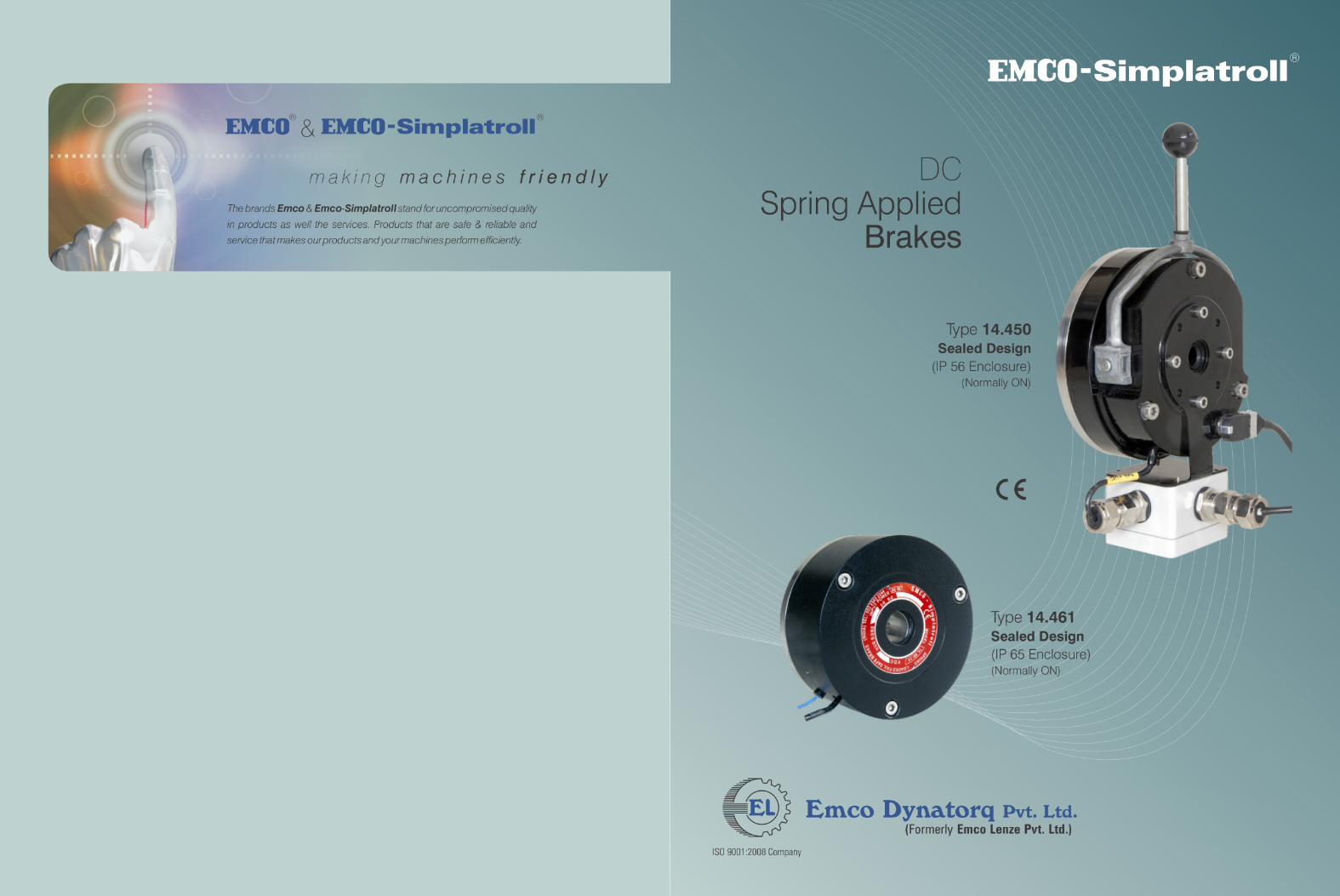
Emco-Simplatroll DC Spring Applied Fail Safe Brake Type 14.450/14.461 are “ Normally On” brake with IP 65
protection. These brakes can be used for all applications where rotating machines must be stopped quickly when
switched off or when power fails ensuring the SAFETY.
Applications
Higher coil insulation available on request.
Standard Indian liner. German liner available on request.
‘Deadman Type’ Manual Release
Brake outer diameter completely enclosed (Higher protection can be easily realised)
Compact Size
Easy Installation
Rust Protection to All Metal Parts
Coil with ‘F’ Class Insulation
Non Asbestos friction liner
Use of Special Bonding Agent
Tacho Mounting provision possible
Microswitch available on request
Low rotor inertia
Cold climate versions available
Salient Features of Type 14.450/14.461
Cranes & Hoists Machine Tools Packaging Machines
Conveyors
Construction Machinery
Printing Machines Elevators Windmills
Textile Machines
Pallet Truck Drives
14.450 14.461
15
18
17
16
14
19
16
47
25
3
89
10
11
12
13
1. Stator Assembly
2. Armature Plate
3. Bush
4. Compression Spring
5. Cheese Head Screw
6. Rubber Bush
7. Hand Release Screw
8. Rotor
9. Hub
10. Big “O” Ring
11. Flange
12. Big “O” Ring
13. Shaft Seal
14. Small “O” Ring
15. Knob
16. H.R. Pin
17. Hand Release Bow
18. H.R. Lever
19. Socket Head Cup Screw, Spring Washer & Plain Washer

DimensionsType 14.450 (With Manual Hand Release & Crouzet Microswitch) DimensionsType 14.450 (With Manual Hand Release & Saia-Burgess Microswitch)
“X” View for Crouzet Microswitch Detail
Important :
For vertical mounting contact us.
For applications with motor operated with VFD contact us for special circuit.
Standard voltages : 24 VDC, 96 VDC, 190 VDC, & 220 VDC (Other voltages on request.)
0P : Coil Power at 20 C
Permissible voltage change : +5% to - 10%
Recommended ISO shaft tolerancesUp to Ø50 mm = k6 Over Ø50 mm = m6
Keyways to DIN 6885 / IS : 2048
Brake Controller can not fit in terminal box. Please mount Brake Controller in the Control Panel.
Brake to be operated with over excitation voltage rectifier.
Class of Insulation : “F” / “H”
Armature Plate & Flange : SS with Zinc plated Olive Green Passivation.
All other components Zinc plated Olive Green Passivation. “X” View for Saia-Burgess Microswitch Detail
‘O’ Ring
h h1a
(air-gap)
L Z
ØD
PC
D-E
ØA
ØJH
7 m
ax.
±3~46
~110
~56.5
Aluminum Terminal Box (IP 66)
Sec. - AA With terminal box
(Use terminal box for brakes size - 18 to 31) (Optional)
Rotary shaft seal size depends upon motor shaft diameter(Optional)
Ød
1(O
ptio
na
l) ØJH
7 m
ax.
L Z
ØD
PC
D-E
ØA
h1
D1
D1
‘O’ RingSec. - AA
Without terminal box
a(air-gap)
h
A
D8
B
Cable gland forthermostat sensorORCable gland forcartridge heater (single phase)(Optional)
ØD6
P.C.D.M.(Optional)
B
A
~75
X
Plug for air-gap checking
‘O’ Ring
Sec. - BB
Plug for air-gap checking
Rotary shaft seal size depends upon motor shaft diameter(Optional)
Cable gland forthermostat sensorORCable gland forcartridge heater (single phase)(Optional)
Sec. - AA Without terminal box
P.C.D.M.(Optional)
D8
A
X
A
B
~75
h1
ØJH
7 m
ax.
L Z
ØD
PC
D-E
ØA
a(air-gap)
h
Ød
1(O
ptio
na
l)
B
ØD6
D1
‘O’ Ring
Microswitch Lead Wire details :
Black : C (Common)
Brown : N.C. (Normally Closed)
Grey : N.O. (Normally Open)
Sealed : IP 56 Protection
Specifications :
Make : Crouzet
Current/Voltage : 5A / 250 V
Thermal Current (A) : 12 ‘O’ Ring
SpacerHex Nut
Crouzet Microswitch
Microswitch Lead Wire details :
Red : C (Common)
Yellow : N.C. (Normally Closed)
Blue : N.O. (Normally Open)
Sealed : IP 67 Protection
Model No. : V4NSUL
Make : Sai-Burgess
BlueYellow
Red
Microswitch
Stator
Arm. Plate
Hex. Bolt
Rubber Bush
Nut
Microswitch Cable
Brake Cable
Cable Gland IP 66 (Pg7)
Input Power Cable (415 V)
Solid State RectifierEH 720 HHD
415 VAC / 190 VDC, 2 AMP
Cable Gland IP 66 (Pg7)for Input power cable
(Dia. not exceeding Ø5 mm)
Input Power Cable(415 V)
Microswitch Cable - 01
Cable Gland IP 66 (Pg7)for Input power cable
(Dia. not exceeding Ø5 mm)
Brake Cable
Cable Gland IP 66 (Pg7)
Solid State RectifierUM 101
M1
Brake Size
P a r a m e t e r s All dimensions are in mm
TorqueM RAT.(Nm)
ØA P.C.D-E D1 d1 h
14.450.06
14.450.08
14.450.10
14.450.12
14.450.14
14.450.16
14.450.18
14.450.20
14.450.23
14.450.25
14.450.31
14.450.40
14.450.50
h1 L ZInput Power
P20 [w]
±0.5
ØD H8
±0.1
P.C.D-M(Optional)
±0.1
ØJH7
+2 ±0.1 -0.2 +0.1
Ød6
±3 ±2
D8 a(air-gap)
±0.05
4
8
16
32
60
100
150
260
315
400
600 / 800
1600
2500
20
25
30
40
50
76
85
100
105
110
140 / 180
340
440
100
120
145
166
180
204
233
271
271
325
325
390
552
31
41
40
45
55
65
75
90
90
120
120
145
210
72
90
112
132
145
170
196
230
230
278
278
325
480
37
49
54
64
75
85
95
110
110
140
140
160
-
10,11,12,14,15
11,12,14,15,19,20
11,12,14,15,19,20
20,24,25
20,24,25,28,30,32
25,28,30,32,34,35
30,35,38,40,42
35,40,42,45,48
35,40,42,45,48
45,48,50,52,55,60,65
45,48,50,52,55,60,65
50,52,55,60,65,7075,80,85,90
60,65,70,75,80,85,9095,100,110
0.2
0.2
0.2
0.3
0.3
0.3
0.4
0.4
0.4
0.5
0.5
0.5
0.8
30
50
33.5
52.5
62.5
95
120
239
239
239
-
-
-
120
140
160
185
210
235
270
308
308
360
-
-
-
1
1.5
2
2
2
2.25
3
3.5
3.5
4.5
4.5
4.5
6.5
18
20
20
25
30
30
35
40
40
50
50
64
83
6
7
9
9
11
11
11
11
11
12.5
16
20
30
36
41
50
55
63.3
72.5
83
96
96
108
121
133.8
183.1
M4 x 4 Nos.
M5 x 4 Nos.
M5 x 4 Nos.
M5 x 4 Nos.
M6 x 4 Nos.
M6 x 4 Nos.
M8 x 4 Nos.
M10 x 4 Nos.
M10 x 4 Nos.
M10 x 4 Nos.
M10 x 4 Nos.
M10 x 4 Nos.
-
M4 x 3 Nos.
M5 x 3 Nos.
M6 x 3 Nos.
M6 x 3 Nos.
M8 x 3 Nos.
M8 x 3 Nos.
M8 x 6 Nos.
M10 x 6 Nos.
M10 x 6 Nos.
M10 x 6 Nos.
M10 x 6 Nos.
M10 x 6 Nos.
M16 x 6 Nos.

The engagement times are valid for
switching on DC side. The table shows the
delay during engagement t11, the rise time
of brake torque t12 and the engagement
time t1=t11 + t12. Disengagement time is
not influenced by DC or AC side switching.
However it can be reduced by suitable
excitation or over excitation.
Operating times
06
08
10
12
14
16
18
20
25
7
10
10
10
15
20
30
50
70
10
25
30
40
50
70
80
150
200
17
35
40
50
65
90
110
200
270
35
65
90
120
150
180
300
400
500
t1 Engagement time
t2 Disengagement time
Selection
1. Select basic brake according to the torque.
Torque (Nm) = 9550 X (Motor kW / RPM) X Safety factor (K)
2. Describe the brake with the ordering parameter. (Type, size, operating voltage and hub bore)
3. Choose optional extras required (G pcd, tacho mounting provision, friction plate (instead of mounting flange), with microswitch).
4. Choose appropriate safety factor for the hoist, lift, inclined conveyors or equipment where holding against gravity is required.
5. Select proper Rectifier considering rated voltage of the brake. If coil operating voltage is 96 or 190 VDC you can use our rectifier. (Call for product details).
6. Choose correct input AC voltage for rectifier.
Load Condition
Low masses, equal loading & non - intermittent operation
Low masses, light shock load & intermittent operation
Medium masses, light shock load & intermittent operation
Large masses, light shock load & intermittent operation
Diesel engine drive
Compressor drive
Non overhauling Loads
Overhauling Loads
Safety Factor (K)
2.0
2.5
3.0
3.0
4-5
5-6
2-3
3-4
06
08
10
12
14
16
18
20
25
100
100
100
100
100
100
100
100
100
87
85
83
81
80
79
77
75
73
12400
10100
8300
6700
6000
5300
4400
3700
3000
Brake SizeAverage
Braking Torque %Maximum Speed
(RPM)
Braking Torque at RPM
80
78
76
74
73
72
70
68
66
65
66
66
66
67
66
66
66
66
1500 3000 MAX.
a(Airgap)‘O’ Ring
d1
L2
h2
d5
d3
d10
d
h3h1
d2
L
Rotary shaft sealsize depend upon
motor shaft diameter
Sec. - AA
L1
‘O’ Ring
a(Airgap)
A
A
DimensionsType 14.461 (Normally ON)
Brake Size
All dimensions are in mm
TorqueM RAT.(Nm)
d1
14.461.06
14.461.08
14.461.10
14.461.12
14.461.14
14.461.16
14.461.18
14.461.20
14.461.25
h1 LInput Power
P20 [w] dH7
±1 -0.2
a(air-gap)
±0.05
4
8
16
32
60
100
150
260
400
20
25
30
40
50
76
85
100
110
10,11,12,14,15
11,12,14,15,19,20,24
11,12,14,15,19,20,24
0.2
0.2
0.2
0.2
0.3
0.3
0.4
0.4
0.5
18
20
20
25
30
30
35
40
50
42
50
58
63.5
76
83
94
111
122.5
20,24,25,28
20,24,25,2830,32,34
25,28,30,3234,35,38
30,35,38,4042,45
35,40,42,4548,50
45,48,50,5255,60,65,70
d2
±0.1
72
90
112
132
145
170
196
230
278
d3
±0.2
16
21
21
26
31
36
46
52
72
d5
±0.5
87
103
130
148
165
200
221
274
326
d10 H8
31
41
44
52
55
70
77
90
120
h2
±0.1
1
1.5
2
2
2
2.25
2.75
3.5
4.5
h3
±0.2
6
7
9
9
11
11
11
11
12.5
L1
410
410
410
410
410
610
610
610
610
±15
L2
7
9
12
12
12
15
15
20
20
P a r a m e t e r s
M4 x 3 Nos.
M5 x 3 Nos.
M6 x 3 Nos.
M6 x 3 Nos.
M8 x 3 Nos.
M8 x 3 Nos.
M8 x 6 Nos.
M10 x 6 Nos.
M10 x 6 Nos.
Important :
For vertical mounting contact us.
For applications with motor operated with VFD contact us for special circuit.
Standard voltages : 24 VDC, 96 VDC, 190 VDC, & 205 VDC (Other voltages on request.)
0P : Coil Power at 20 C
Permissible voltage change : +5% to - 10%
Recommended ISO shaft tolerancesUp to Ø50 mm = k6 Over Ø50 mm = m6
Keyways to DIN 6885 / IS : 2048 (js9)
Brake to be operated with over excitation voltage rectifier.
Class of Insulation : “F” / “H”
*Non Std. Keyway
Non andjustable air-gap.
Armature Plate & Flange : SS with Zinc plated Olive Green Passivation.
All other components Zinc plated Olive Green Passivation.
t1ms t2msBrake Size
14.450 14.461 14.450 14.461