Embed Size (px)
Citation preview

Model 1900B, 1901B, 1902B
Switching DC Power Supply
INSTRUCTION MANUAL
1
1 Safety Summary
The following safety precautions apply to both operating and maintenance personnel and must be observed during all phases of operation, service, and repair of this instrument. Before applying power, follow the installation instructions and become familiar with the operating instructions for this instrument.
GROUND THE INSTRUMENT
To minimize shock hazard, the instrument chassis and cabinet must be connected to an electrical ground. This instrument is grounded through the ground conductor of the supplied, three-conductor ac power cable. The power cable must be plugged into an approved three-conductor electrical outlet. Do not alter the ground connection. Without the protective ground connection, all accessible conductive parts (including control knobs) can render an electric shock. The power jack and mating plug of the power cable meet IEC safety standards.
DO NOT OPERATE IN AN EXPLOSIVE ATMOSPHERE
Do not operate the instrument in the presence of flammable gases or fumes. Operation of any electrical instrument in such an environment constitutes a definite safety hazard.
KEEP AWAY FROM LIVE CIRCUITS
Instrument covers must not be removed by operating personnel. Component replacement and internal adjustments must be made by qualified maintenance personnel. Disconnect the power cord before removing the instrument covers and replacing components. Under certain conditions, even with the power cable removed, dangerous voltages may exist. To avoid injuries, always disconnect power and discharge circuits before touching them.
DO NOT SERVICE OR ADJUST ALONE
Do not attempt any internal service or adjustment unless another person, capable of rendering first aid and resuscitation, is present.
DO NOT SUBSTITUTE PARTS OR MODIFY THE INSTRUMENT
Do not install substitute parts or perform any unauthorized modifications to this instrument. Return the instrument to B&K Precision for service and repair to ensure that safety features are maintained.
2
WARNINGS AND CAUTIONS
WARNING and CAUTION statements, such as the following examples, denote a hazard and appear throughout this manual. Follow all instructions contained in these statements.
A WARNING statement calls attention to an operating procedure, practice, or condition, which, if not followed correctly, could result in injury or death to personnel.
A CAUTION statement calls attention to an operating procedure, practice, or condition, which, if not followed correctly, could result in damage to or destruction of parts or the entire product.
WARNING:
Do not alter the ground connection. Without the protective ground connection, all accessible conductive parts (including control knobs) can render an electric shock. The power jack and mating plug of the power cable meet IEC safety standards.
WARNING:
To avoid electrical shock hazard, disconnect power cord before removing covers. Refer servicing to qualified personnel.
CAUTION:
Before connecting the line cord to the AC mains, check the rear panel AC line voltage indicator. Applying a line voltage other than the indicated voltage can destroy the AC line fuses. For continued fire protection, replace fuses only with those of the specified voltage and current ratings.
CAUTION:
This product uses components which can be damaged by electro-static discharge (ESD). To avoid damage, be sure to follow proper procedures for handling, storing and transporting parts and subassemblies which contain ESD-sensitive components.
SAFETY SYMBOLS
This symbol on an instrument indicates that the user should refer to the
operating instructions located in the manual.
Certification
We certify that this product met its published specifications at time of shipment from the
factory.
3
Compliance Statements
Disposal of Old Electrical & Electronic Equipment (Applicable in the European Union and
other European countries with separate collection systems)
This product is subject to Directive 2002/96/EC of the European
Parliament and the Council of the European Union on waste
electrical and electronic equipment (WEEE), and in jurisdictions
adopting that Directive, is marked as being put on the market
after August 13, 2005, and should not be disposed of as
unsorted municipal waste. Please utilize your local WEEE
collection facilities in the disposition of this product and
otherwise observe all applicable requirements.
4
Contents 1 Safety Summary ........................................................................................ 1
2 Introduction .............................................................................................. 6
3 Controls and Indicators ............................................................................. 7
3.1 Front Panel ........................................................................................ 7
3.2 Rear Panel ......................................................................................... 8
4 Operating Instructions .............................................................................. 9
4.1 Using the Power Supply .................................................................. 10
4.1.1 Connection .............................................................................. 10
4.1.2 Self Test Sequence .................................................................. 10
4.1.3 Control Knobs .......................................................................... 12
4.1.4 Manually Zeroing Current Meter Offset ................................. 13
4.1.5 Using Both Main and Auxiliary Outputs .................................. 14
4.2 Control Modes ................................................................................ 14
4.2.1 Normal Mode .......................................................................... 15
4.2.2 Preset Mode ............................................................................ 15
4.2.3 Analog Remote Control Mode ................................................ 16
4.2.4 Set Mode ................................................................................. 16
4.3 Remote Sense ................................................................................. 18
4.3.1 Connection .............................................................................. 18
5
4.3.2 Disconnection .......................................................................... 19
5 Remote Control ....................................................................................... 19
5.1 Analog Remote Control ................................................................... 20
5.1.1 Remote Control Connector Setup ........................................... 20
5.1.2 Using Two External Variable DC Voltage Sources ................... 21
5.1.3 Using Two 5 kΩ Variable Resistors .......................................... 23
5.1.4 Enable and Disable the Output ............................................... 24
5.2 PC Interface Control ........................................................................ 25
6 Faults and Troubleshooting .................................................................... 26
6.1 OVP: Overvoltage Protection ......................................................... 26
6.2 OTP: Overtemperature Protection ................................................. 26
6.3 OLP: Overload Protection ............................................................... 27
6.4 Upper Voltage Limit (UVL) and Upper Current Limit (UCL) ............ 28
6.5 Fuse Replacement ........................................................................... 29
7 Specifications .......................................................................................... 30
8 Certification ............................................................................................ 32
9 Service Information ................................................................................ 33
10 Limited Two-Year Warranty .................................................................... 34
6
2 Introduction
B&K Precision models 1900B, 1901B, and 1902B are laboratory grade switching mode
DC power supplies with high current output in a small form factor and lightweight
package. The 1900B Series provide different configurations of high output voltage or
high output current and make setting voltage and current levels fast and precise
through its dual action, course/fine rotary encoder control. In addition to its constant
voltage (CV) and constant current (CC) modes, the high efficiency DC power supply
offers a unique solution with its preset and analog remote control modes. Save up to
three different presets of voltage and current values for quick recall. The analog
remote control function allows the output power, voltage, and current to be adjusted
without touching the front panel of the power supply. A remote sense terminal
(model 1900B only) is also available for use to compensate for voltage drop across
load leads. These features make the 1900B Series suitable for a wide range of
applications including production testing, telecommunications, R&D, service, and
university labs.
Features
Automatic CV/CC crossover operation
Up to 60 A output current
Lightweight and compact
Rotary encoder control for precise voltage and current setting
3 user-defined voltage and current presets
Analog remote control function
Remote sense terminal (model 1900B only)
USB interface
Front panel auxiliary output
Overvoltage, overtemperature, and overload protection
7
3 Controls and Indicators
3.1 Front Panel
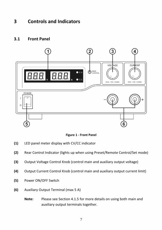
Figure 1 - Front Panel
(1) LED panel meter display with CV/CC indicator
(2) Rear Control Indicator (lights up when using Preset/Remote Control/Set mode)
(3) Output Voltage Control Knob (control main and auxiliary output voltage)
(4) Output Current Control Knob (control main and auxiliary output current limit)
(5) Power ON/OFF Switch
(6) Auxiliary Output Terminal (max 5 A)
Note: Please see Section 4.1.5 for more details on using both main and
auxiliary output terminals together.
8
3.2 Rear Panel
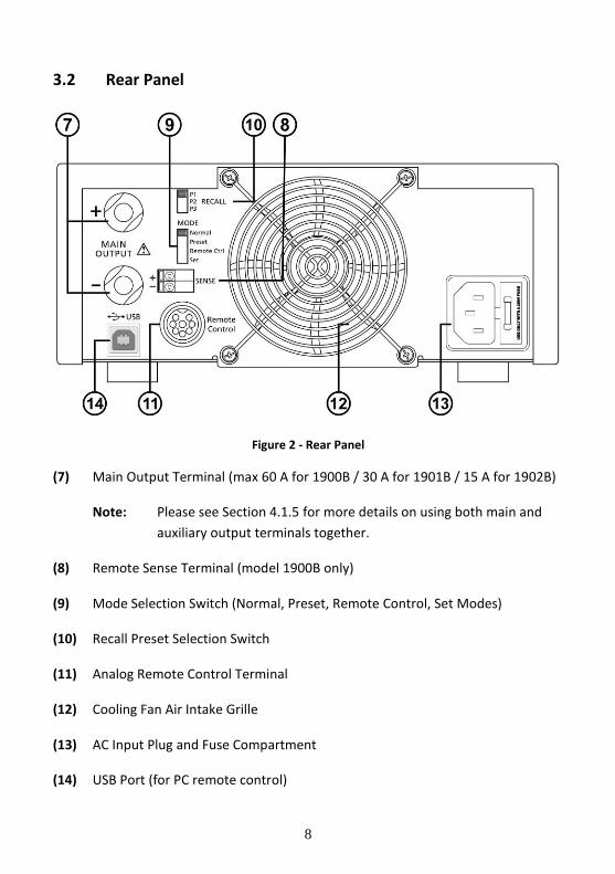
Figure 2 - Rear Panel
(7) Main Output Terminal (max 60 A for 1900B / 30 A for 1901B / 15 A for 1902B)
Note: Please see Section 4.1.5 for more details on using both main and
auxiliary output terminals together.
(8) Remote Sense Terminal (model 1900B only)
(9) Mode Selection Switch (Normal, Preset, Remote Control, Set Modes)
(10) Recall Preset Selection Switch
(11) Analog Remote Control Terminal
(12) Cooling Fan Air Intake Grille
(13) AC Input Plug and Fuse Compartment
(14) USB Port (for PC remote control)
9
4 Operating Instructions
Safety Precautions
Never short the remote sense terminal.
This power supply is for indoor use only.
Do not expose the power supply to sun, high humidity, or dusty
environments.
Never remove the metal cover of the power supply while AC power is
connected.
Never touch the unit when your hands are wet.
Never block the ventilation slots and cooling fan air intake window.
Never attempt to repair the power supply. Incorrect re-assembly may
result in a risk of electric shock or fire.
Never use the power supply for a load requiring higher current than the
designed value. Otherwise it may damage the power supply.
Place the power supply on a flat surface with sufficient clearance and dry,
dust-free surroundings for ventilation.
This series has three models with different output voltage and current ranges. Make
sure you have purchased the correct one.
Model Number Output Voltage Range Total Rated Current
1900B 1 – 16 V 0 – 60 A
1901B 1 – 32 V 0 – 30 A
1902B 1 – 60 V 0 – 15 A
Table 1 - Model Table
10
4.1 Using the Power Supply
4.1.1 Connection
To connect the equipment to the power supply, follow the steps below.
1. Check the rating label of the power supply and confirm that it complies with
your AC mains voltage.
2. Connect the power supply to the AC mains using the provided power cord
and make sure the Mode Selection Switch is in the Normal position.
3. Hook up the red (+) terminal to the positive polarity input of the equipment
and the black (-) terminal to the negative polarity input of the equipment.
4. Switch on the power supply first. The panel meter and green CV indicator
should light up again.
5. Switch on the equipment. The panel meter and green CV indicator should
still remain green.
6. When an operation is finished, switch off the equipment first and then
switch off the power supply.
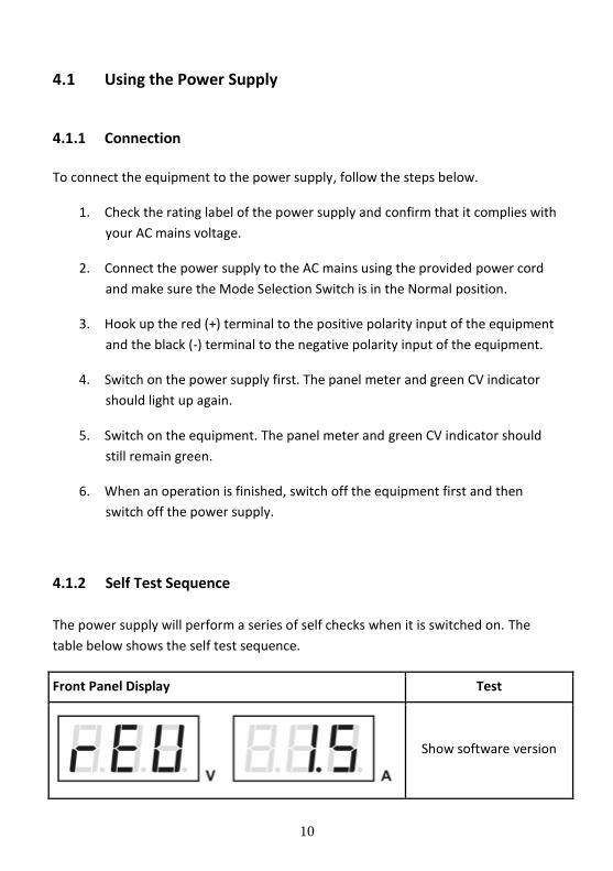
4.1.2 Self Test Sequence
The power supply will perform a series of self checks when it is switched on. The
table below shows the self test sequence.
Front Panel Display Test
Show software version
11
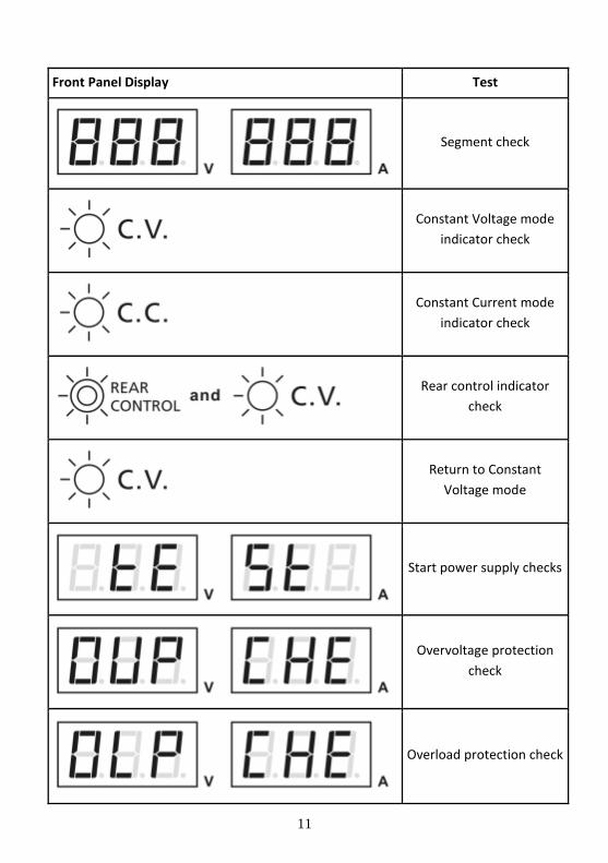
Front Panel Display Test
Segment check
Constant Voltage mode
indicator check
Constant Current mode
indicator check
Rear control indicator
check
Return to Constant
Voltage mode
Start power supply checks
Overvoltage protection
check
Overload protection check
12
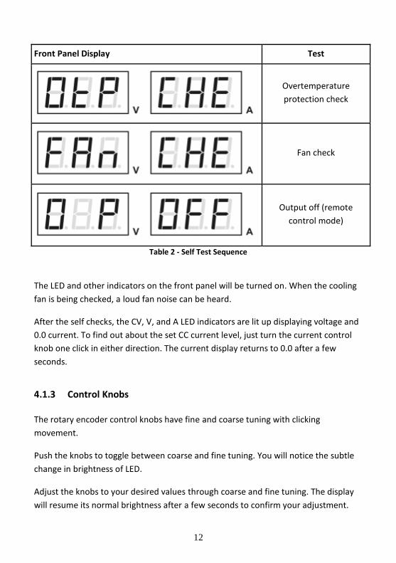
Front Panel Display Test
Overtemperature
protection check
Fan check
Output off (remote
control mode)
Table 2 - Self Test Sequence
The LED and other indicators on the front panel will be turned on. When the cooling
fan is being checked, a loud fan noise can be heard.
After the self checks, the CV, V, and A LED indicators are lit up displaying voltage and
0.0 current. To find out about the set CC current level, just turn the current control
knob one click in either direction. The current display returns to 0.0 after a few
seconds.
4.1.3 Control Knobs
The rotary encoder control knobs have fine and coarse tuning with clicking
movement.
Push the knobs to toggle between coarse and fine tuning. You will notice the subtle
change in brightness of LED.
Adjust the knobs to your desired values through coarse and fine tuning. The display
will resume its normal brightness after a few seconds to confirm your adjustment.
13
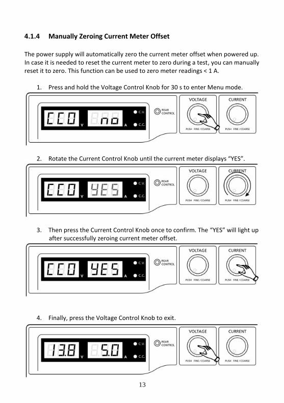
4.1.4 Manually Zeroing Current Meter Offset
The power supply will automatically zero the current meter offset when powered up. In case it is needed to reset the current meter to zero during a test, you can manually reset it to zero. This function can be used to zero meter readings < 1 A.
1. Press and hold the Voltage Control Knob for 30 s to enter Menu mode.
2. Rotate the Current Control Knob until the current meter displays “YES”.
3. Then press the Current Control Knob once to confirm. The “YES” will light up after successfully zeroing current meter offset.
4. Finally, press the Voltage Control Knob to exit.
14
4.1.5 Using Both Main and Auxiliary Outputs
The power supply has a main output in the rear and an auxiliary output in the front
that can be used separately or together.
The main and auxiliary output both share the same voltage and current control knobs
and will output the same voltage and current up to the maximum output ratings of
the power supply and terminals. When using both the main and auxiliary outputs
together, the power supply will automatically total the currents supplied to both
terminals up to the current limit of the power supply and show the total current on
the display.
For example, setting the voltage and current outputs for model 1900B (1-16 V, 0-60
A) to 16 V and 60 A would output 16 V at both main and auxiliary terminals and allow
you to draw up to a total of 60 A between the two terminals. If there is a 5 A load at
the auxiliary terminal, the most current you can draw from the main output is 55 A.
If the power supply reaches its set current limit at any time, the power supply will go
into CC mode and the loads together will draw up to the total value of the current
limit. Distribution of current between the main and auxiliary terminals will vary
depending on the loads.
Note: 1900B: Total rated current (Aux. + Main) is 60 A
1901B: Total rated current (Aux. + Main) is 30 A
1902B: Total rated current (Aux. + Main) is 15 A
4.2 Control Modes
There are four different control modes for the power supply:
Normal
Preset
Remote Control (Analog)
Set
15
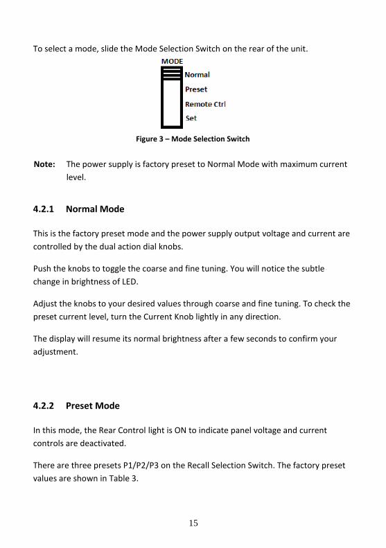
To select a mode, slide the Mode Selection Switch on the rear of the unit.
Figure 3 – Mode Selection Switch
Note: The power supply is factory preset to Normal Mode with maximum current
level.
4.2.1 Normal Mode
This is the factory preset mode and the power supply output voltage and current are
controlled by the dual action dial knobs.
Push the knobs to toggle the coarse and fine tuning. You will notice the subtle
change in brightness of LED.
Adjust the knobs to your desired values through coarse and fine tuning. To check the
preset current level, turn the Current Knob lightly in any direction.
The display will resume its normal brightness after a few seconds to confirm your
adjustment.
4.2.2 Preset Mode
In this mode, the Rear Control light is ON to indicate panel voltage and current
controls are deactivated.
There are three presets P1/P2/P3 on the Recall Selection Switch. The factory preset
values are shown in Table 3.
16
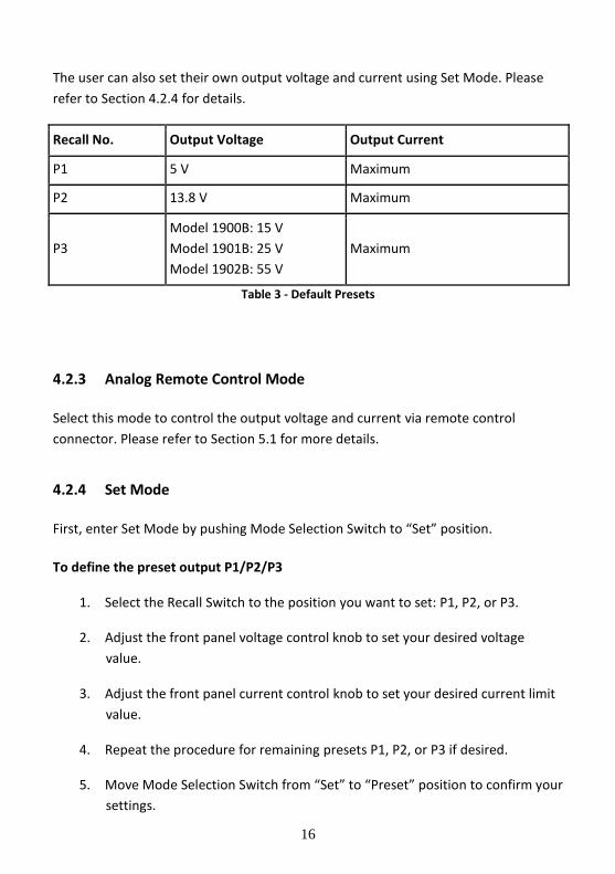
The user can also set their own output voltage and current using Set Mode. Please
refer to Section 4.2.4 for details.
Recall No. Output Voltage Output Current
P1 5 V Maximum
P2 13.8 V Maximum
P3
Model 1900B: 15 V
Model 1901B: 25 V
Model 1902B: 55 V
Maximum
Table 3 - Default Presets
4.2.3 Analog Remote Control Mode
Select this mode to control the output voltage and current via remote control
connector. Please refer to Section 5.1 for more details.
4.2.4 Set Mode
First, enter Set Mode by pushing Mode Selection Switch to “Set” position.
To define the preset output P1/P2/P3
1. Select the Recall Switch to the position you want to set: P1, P2, or P3.
2. Adjust the front panel voltage control knob to set your desired voltage
value.
3. Adjust the front panel current control knob to set your desired current limit
value.
4. Repeat the procedure for remaining presets P1, P2, or P3 if desired.
5. Move Mode Selection Switch from “Set” to “Preset” position to confirm your
settings.
17
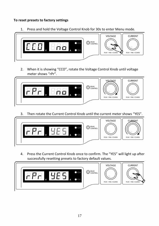
To reset presets to factory settings
1. Press and hold the Voltage Control Knob for 30s to enter Menu mode.
2. When it is showing “CCO”, rotate the Voltage Control Knob until voltage meter shows “rPr”.
3. Then rotate the Current Control Knob until the current meter shows “YES”.
4. Press the Current Control Knob once to confirm. The “YES” will light up after successfully resetting presets to factory default values.
18
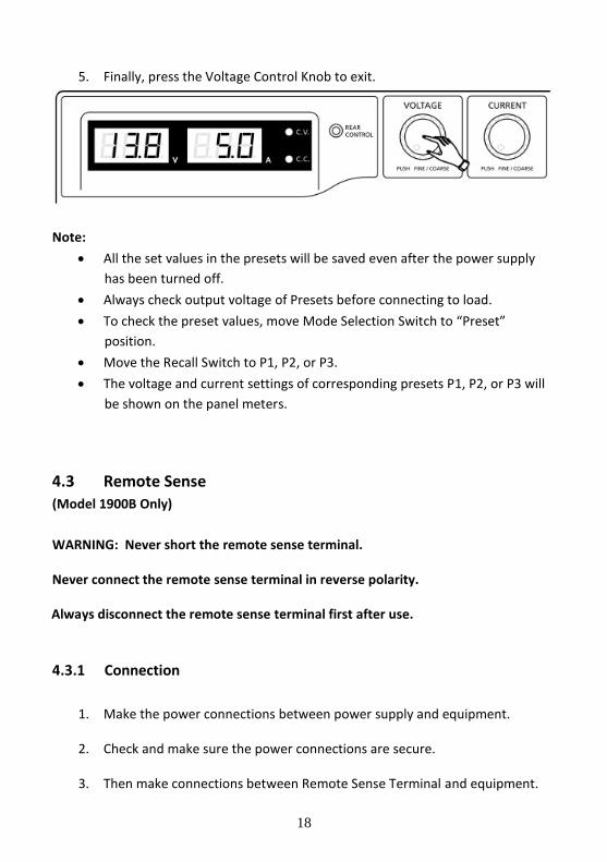
5. Finally, press the Voltage Control Knob to exit.
Note:
All the set values in the presets will be saved even after the power supply
has been turned off.
Always check output voltage of Presets before connecting to load.
To check the preset values, move Mode Selection Switch to “Preset”
position.
Move the Recall Switch to P1, P2, or P3.
The voltage and current settings of corresponding presets P1, P2, or P3 will
be shown on the panel meters.
4.3 Remote Sense (Model 1900B Only)
WARNING: Never short the remote sense terminal.
Never connect the remote sense terminal in reverse polarity.
Always disconnect the remote sense terminal first after use.
4.3.1 Connection
1. Make the power connections between power supply and equipment.
2. Check and make sure the power connections are secure.
3. Then make connections between Remote Sense Terminal and equipment.
19
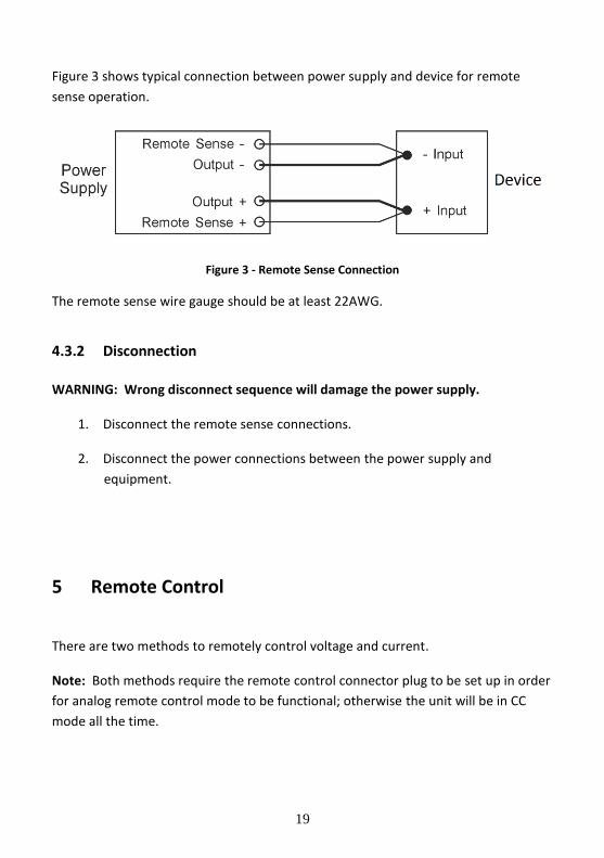
Figure 3 shows typical connection between power supply and device for remote
sense operation.
Figure 3 - Remote Sense Connection
The remote sense wire gauge should be at least 22AWG.
4.3.2 Disconnection
WARNING: Wrong disconnect sequence will damage the power supply.
1. Disconnect the remote sense connections.
2. Disconnect the power connections between the power supply and
equipment.
5 Remote Control
There are two methods to remotely control voltage and current.
Note: Both methods require the remote control connector plug to be set up in order
for analog remote control mode to be functional; otherwise the unit will be in CC
mode all the time.
20
5.1 Analog Remote Control
5.1.1 Remote Control Connector Setup
Set up the provided remote connector plug.
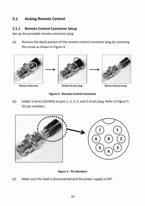
(a) Remove the black portion of the remote control connector plug by removing
the screw as shown in Figure 4.
Figure 4 - Remote Control Connector
(b) Solder 5 wires (22AWG) to pins 1, 2, 3, 4, and 5 of pin plug. Refer to Figure 5
for pin numbers.
Figure 5 - Pin Numbers
(c) Make sure the load is disconnected and the power supply is OFF.
21
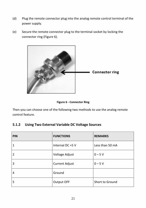
(d) Plug the remote connector plug into the analog remote control terminal of the
power supply.
(e) Secure the remote connector plug to the terminal socket by locking the
connector ring (Figure 6).
Figure 6 - Connector Ring
Then you can choose one of the following two methods to use the analog remote
control feature.
5.1.2 Using Two External Variable DC Voltage Sources
PIN FUNCTIONS REMARKS
1 Internal DC +5 V Less than 50 mA
2 Voltage Adjust 0 – 5 V
3 Current Adjust 0 – 5 V
4 Ground
5 Output OFF Short to Ground
22
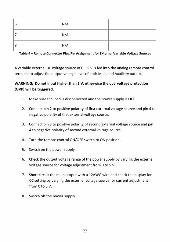
6 N/A
7 N/A
8 N/A
Table 4 – Remote Connector Plug Pin Assignment for External Variable Voltage Sources
A variable external DC voltage source of 0 – 5 V is fed into the analog remote control
terminal to adjust the output voltage level of both Main and Auxiliary output.
WARNING: Do not input higher than 5 V, otherwise the overvoltage protection
(OVP) will be triggered.
1. Make sure the load is disconnected and the power supply is OFF.
2. Connect pin 2 to positive polarity of first external voltage source and pin 4 to
negative polarity of first external voltage source.
3. Connect pin 3 to positive polarity of second external voltage source and pin
4 to negative polarity of second external voltage source.
4. Turn the remote control ON/OFF switch to ON position.
5. Switch on the power supply.
6. Check the output voltage range of the power supply by varying the external
voltage source for voltage adjustment from 0 to 5 V.
7. Short circuit the main output with a 12AWG wire and check the display for
CC setting by varying the external voltage source for current adjustment
from 0 to 5 V.
8. Switch off the power supply.
23
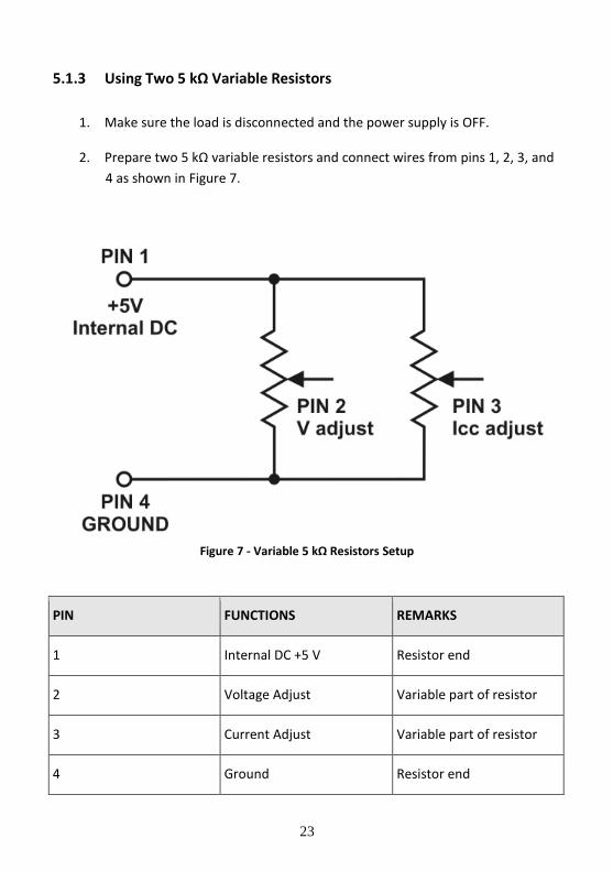
5.1.3 Using Two 5 kΩ Variable Resistors
1. Make sure the load is disconnected and the power supply is OFF.
2. Prepare two 5 kΩ variable resistors and connect wires from pins 1, 2, 3, and
4 as shown in Figure 7.
Figure 7 - Variable 5 kΩ Resistors Setup
PIN FUNCTIONS REMARKS
1 Internal DC +5 V Resistor end
2 Voltage Adjust Variable part of resistor
3 Current Adjust Variable part of resistor
4 Ground Resistor end
24
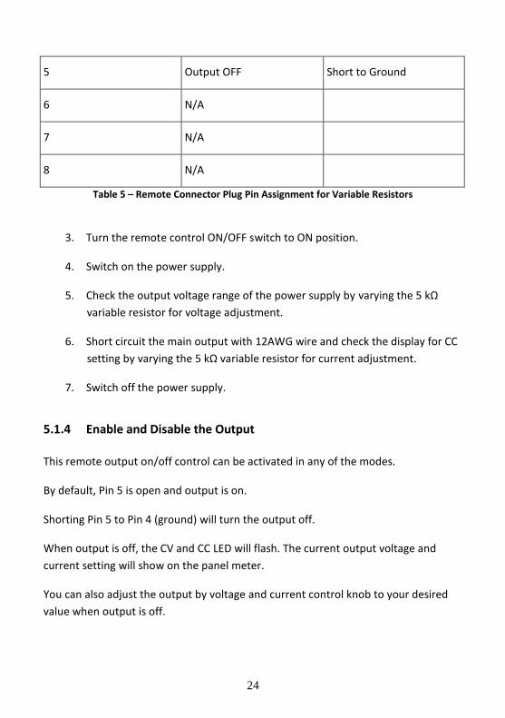
5 Output OFF Short to Ground
6 N/A
7 N/A
8 N/A
Table 5 – Remote Connector Plug Pin Assignment for Variable Resistors
3. Turn the remote control ON/OFF switch to ON position.
4. Switch on the power supply.
5. Check the output voltage range of the power supply by varying the 5 kΩ
variable resistor for voltage adjustment.
6. Short circuit the main output with 12AWG wire and check the display for CC
setting by varying the 5 kΩ variable resistor for current adjustment.
7. Switch off the power supply.
5.1.4 Enable and Disable the Output
This remote output on/off control can be activated in any of the modes.
By default, Pin 5 is open and output is on.
Shorting Pin 5 to Pin 4 (ground) will turn the output off.
When output is off, the CV and CC LED will flash. The current output voltage and
current setting will show on the panel meter.
You can also adjust the output by voltage and current control knob to your desired
value when output is off.
25
5.2 PC Interface Control
The power supply provides a USB interface for remote control via PC. Please see programming manual for more information on the PC interface control setup, software, and remote commands. The software and programming manual can be downloaded from B&K Precision’s website at www.bkprecision.com. Note: The power supply must be in Normal Mode and operated as a standalone equipment (not connected in series or parallel with multiple supplies) for PC interface control.
26
6 Faults and Troubleshooting
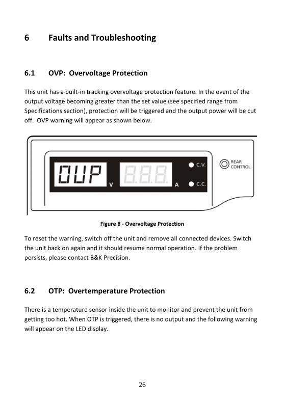
6.1 OVP: Overvoltage Protection
This unit has a built-in tracking overvoltage protection feature. In the event of the
output voltage becoming greater than the set value (see specified range from
Specifications section), protection will be triggered and the output power will be cut
off. OVP warning will appear as shown below.
Figure 8 - Overvoltage Protection
To reset the warning, switch off the unit and remove all connected devices. Switch
the unit back on again and it should resume normal operation. If the problem
persists, please contact B&K Precision.
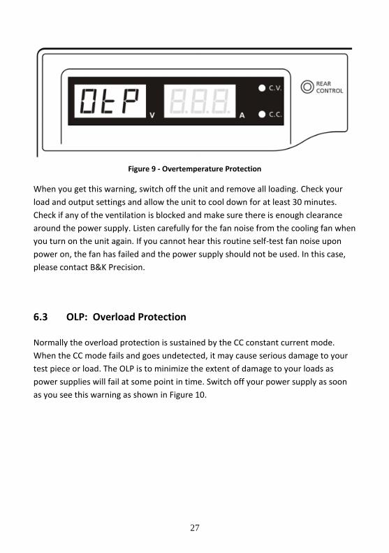
6.2 OTP: Overtemperature Protection
There is a temperature sensor inside the unit to monitor and prevent the unit from
getting too hot. When OTP is triggered, there is no output and the following warning
will appear on the LED display.
27
Figure 9 - Overtemperature Protection
When you get this warning, switch off the unit and remove all loading. Check your
load and output settings and allow the unit to cool down for at least 30 minutes.
Check if any of the ventilation is blocked and make sure there is enough clearance
around the power supply. Listen carefully for the fan noise from the cooling fan when
you turn on the unit again. If you cannot hear this routine self-test fan noise upon
power on, the fan has failed and the power supply should not be used. In this case,
please contact B&K Precision.
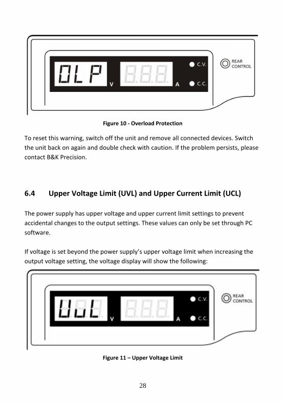
6.3 OLP: Overload Protection
Normally the overload protection is sustained by the CC constant current mode.
When the CC mode fails and goes undetected, it may cause serious damage to your
test piece or load. The OLP is to minimize the extent of damage to your loads as
power supplies will fail at some point in time. Switch off your power supply as soon
as you see this warning as shown in Figure 10.
28
Figure 10 - Overload Protection
To reset this warning, switch off the unit and remove all connected devices. Switch
the unit back on again and double check with caution. If the problem persists, please
contact B&K Precision.
6.4 Upper Voltage Limit (UVL) and Upper Current Limit (UCL)
The power supply has upper voltage and upper current limit settings to prevent
accidental changes to the output settings. These values can only be set through PC
software.
If voltage is set beyond the power supply’s upper voltage limit when increasing the
output voltage setting, the voltage display will show the following:
Figure 11 – Upper Voltage Limit
29
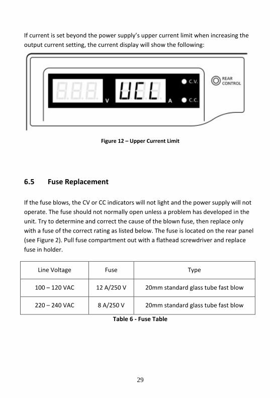
If current is set beyond the power supply’s upper current limit when increasing the
output current setting, the current display will show the following:
Figure 12 – Upper Current Limit
6.5 Fuse Replacement
If the fuse blows, the CV or CC indicators will not light and the power supply will not
operate. The fuse should not normally open unless a problem has developed in the
unit. Try to determine and correct the cause of the blown fuse, then replace only
with a fuse of the correct rating as listed below. The fuse is located on the rear panel
(see Figure 2). Pull fuse compartment out with a flathead screwdriver and replace
fuse in holder.
Line Voltage Fuse Type
100 – 120 VAC 12 A/250 V 20mm standard glass tube fast blow
220 – 240 VAC 8 A/250 V 20mm standard glass tube fast blow
Table 6 - Fuse Table
30
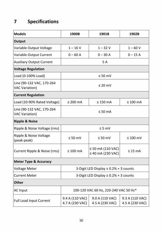
7 Specifications
Models 1900B 1901B 1902B
Output
Variable Output Voltage 1 – 16 V 1 – 32 V 1 – 60 V
Variable Output Current 0 – 60 A 0 – 30 A 0 – 15 A
Auxiliary Output Current 5 A
Voltage Regulation
Load (0-100% Load) ≤ 50 mV
Line (90-132 VAC, 170-264 VAC Variation)
≤ 20 mV
Current Regulation
Load (10-90% Rated Voltage) ≤ 200 mA ≤ 150 mA ≤ 100 mA
Line (90-132 VAC, 170-264 VAC Variation)
≤ 50 mA
Ripple & Noise
Ripple & Noise Voltage (rms) ≤ 5 mV
Ripple & Noise Voltage (peak-peak)
≤ 50 mV ≤ 50 mV ≤ 100 mV
Current Ripple & Noise (rms) ≤ 100 mA ≤ 50 mA (110 VAC) ≤ 40 mA (230 VAC)
≤ 15 mA
Meter Type & Accuracy
Voltage Meter 3-Digit LED Display ± 0.2% + 3 counts
Current Meter 3-Digit LED Display ± 0.2% + 3 counts
Other
AC Input 100-120 VAC 60 Hz, 220-240 VAC 50 Hz*
Full Load Input Current 9.4 A (110 VAC) 4.7 A (230 VAC)
9.0 A (110 VAC) 4.5 A (230 VAC)
9.3 A (110 VAC) 4.5 A (230 VAC)
31
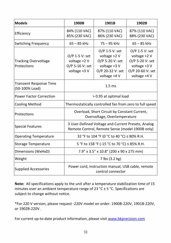
Models 1900B 1901B 1902B
Efficiency 84% (110 VAC) 85% (230 VAC)
87% (110 VAC) 86% (230 VAC)
87% (110 VAC) 88% (230 VAC)
Switching Frequency 65 – 85 kHz 75 – 95 kHz 65 – 85 kHz
Tracking Overvoltage Protections
O/P 1-5 V: set voltage +2 V
O/P 5-16 V: set voltage +3 V
O/P 1-5 V: set voltage +2 V
O/P 5-20 V: set voltage +3 V
O/P 20-32 V: set voltage +4 V
O/P 1-5 V: set voltage +2 V
O/P 5-20 V: set voltage +3 V
O/P 20-60 V: set voltage +4 V
Transient Response Time (50-100% Load)
1.5 ms
Power Factor Correction > 0.95 at optimal load
Cooling Method Thermostatically controlled fan from zero to full speed
Protections Overload, Short Circuit by Constant Current,
Overvoltage, Overtemperature
Special Features 3 User-Defined Voltage and Current Presets, Analog Remote Control, Remote Sense (model 1900B only)
Operating Temperature 32 °F to 104 °F (0 °C to 40 °C) ≤ 80% R.H.
Storage Temperature 5 °F to 158 °F (-15 °C to 70 °C) ≤ 85% R.H.
Dimensions (WxHxD) 7.9” x 3.5” x 10.8” (200 x 90 x 275 mm)
Weight 7 lbs (3.2 kg)
Supplied Accessories Power cord, instruction manual, USB cable, remote
control connector
Note: All specifications apply to the unit after a temperature stabilization time of 15 minutes over an ambient temperature range of 23 °C ± 5 °C. Specifications are subject to change without notice. *For 220 V version, please request -220V model on order: 1900B-220V, 1901B-220V, or 1902B-220V. For current up-to-date product information, please visit www.bkprecision.com
32
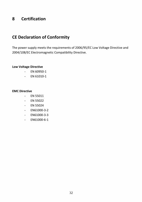
8 Certification
CE Declaration of Conformity
The power supply meets the requirements of 2006/95/EC Low Voltage Directive and
2004/108/EC Electromagnetic Compatibility Directive.
Low Voltage Directive
- EN 60950-1
- EN 61010-1
EMC Directive
- EN 55011
- EN 55022
- EN 55024
- EN61000-3-2
- EN61000-3-3
- EN61000-6-1
33
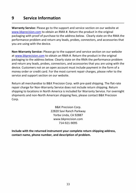
9 Service Information Warranty Service: Please go to the support and service section on our website at www.bkprecision.com to obtain an RMA #. Return the product in the original packaging with proof of purchase to the address below. Clearly state on the RMA the performance problem and return any leads, probes, connectors, and accessories that you are using with the device. Non-Warranty Service: Please go to the support and service section on our website at www.bkprecision.com to obtain an RMA #. Return the product in the original packaging to the address below. Clearly state on the RMA the performance problem and return any leads, probes, connectors, and accessories that you are using with the device. Customers not on an open account must include payment in the form of a money order or credit card. For the most current repair charges, please refer to the service and support section on our website. Return all merchandise to B&K Precision Corp. with pre-paid shipping. The flat-rate repair charge for Non-Warranty Service does not include return shipping. Return shipping to locations in North America is included for Warranty Service. For overnight shipments and non-North American shipping fees, please contact B&K Precision Corp.
B&K Precision Corp. 22820 Savi Ranch Parkway
Yorba Linda, CA 92887 www.bkprecision.com
714-921-9095 Include with the returned instrument your complete return shipping address, contact name, phone number, and description of problem.

34
10 Limited Two-Year Warranty B&K Precision Corp. warrants to the original purchaser that its products and the component parts thereof will be free from defects in workmanship and materials, for a period of two years from date of purchase. B&K Precision Corp. will, without charge, repair or replace, at its option, defective product or component parts. Returned product must be accompanied by proof of the purchase date in the form of a sales receipt. To help us better serve you, please complete the warranty registration for your new instrument via our website www.bkprecision.com Exclusions: This warranty does not apply in the event of misuse or abuse of the product or as a result of unauthorized alterations or repairs. The warranty is void if the serial number is altered, defaced, or removed. B&K Precision Corp. shall not be liable for any consequential damages, including without limitation, damages resulting from loss of use. Some states do not allow limitations of incidental or consequential damages. So the above limitation or exclusion may not apply to you. This warranty gives you specific rights and you may have other rights, which vary from state-to-state.
B&K Precision Corp. 22820 Savi Ranch Parkway
Yorba Linda, CA 92887 www.bkprecision.com
714-921-9095

(Page intentionally left blank)

Printed in Hong Kong v022516
22820 Savi Ranch Parkway
Yorba Linda, CA 92887
www.bkprecision.com
© 2016 B&K Precision Corp.


![TME-DC [ ] - Sew Many Parts, Inc. of Contents z TME-DC GENERAL VIEW z TME-DC FRAME … CD-1 z TME-DC TABLE … CD-2-1 z TME-DC AUTO SUB TABLE …](https://img.pdfslide.us/doc/110x75/5b1d28797f8b9add7f8b64eb/tme-dc-sew-many-parts-inc-of-contents-z-tme-dc-general-view-z-tme-dc-frame.jpg)