Embed Size (px)
Citation preview
Series SMS / PMS / PMK 1/2" MTG / MCS / MTP 1/2"
ISO 9001 / ISO 14001
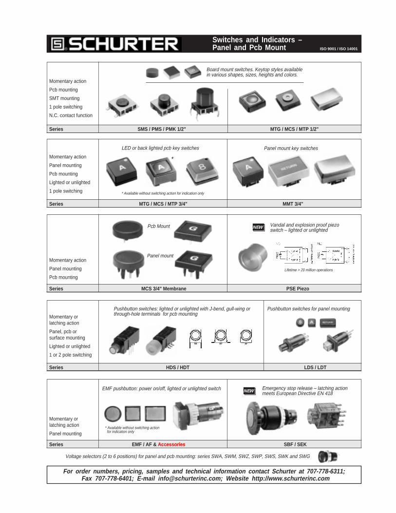
Switches and Indicators –Panel and Pcb Mount
Momentary action
Pcb mounting
SMT mounting
1 pole switching
N.C. contact function
Series MTG / MCS / MTP 3/4" MMT 3/4"
Momentary action
Panel mounting
Pcb mounting
Lighted or unlighted
1 pole switching
LED or back lighted pcb key switches
Panel mount
Pcb Mount
Momentary action
Panel mounting
Pcb mounting
Series MCS 3/4" Membrane PSE Piezo
For order numbers, pricing, samples and technical information contact Schurter at 707-778-6311;Fax 707-778-6401; E-mail [email protected]; Website http://www.schurterinc.com
Vandal and explosion proof piezoswitch – lighted or unlightedNEW
Lifetime > 20 million operations
Panel mount key switches
*
Series HDS / HDT LDS / LDT
Momentary orlatching action
Panel, pcb orsurface mounting
Lighted or unlighted
1 or 2 pole switching
Series EMF / AF & Accessories SBF / SEK
NEW Emergency stop release – latching actionmeets European Directive EN 418
Momentary orlatching action
Panel mounting
EMF pushbutton: power on/off, lighted or unlighted switch
* Available without switching actionfor indication only
* Available without switching action for indication only
Board mount switches. Keytop styles availablein various shapes, sizes, heights and colors.
Pushbutton switches: lighted or unlighted with J-bend, gull-wing orthrough-hole terminals for pcb mounting
Pushbutton switches for panel mounting
Voltage selectors (2 to 6 positions) for panel and pcb mounting: series SWA, SWM, SWZ, SWP, SWS, SWK and SWG
Phone 707-778-6311 ¥ Fax 707-778-6401 ¥ E-mail [email protected] ¥ Website http://www.schurterinc.com 5
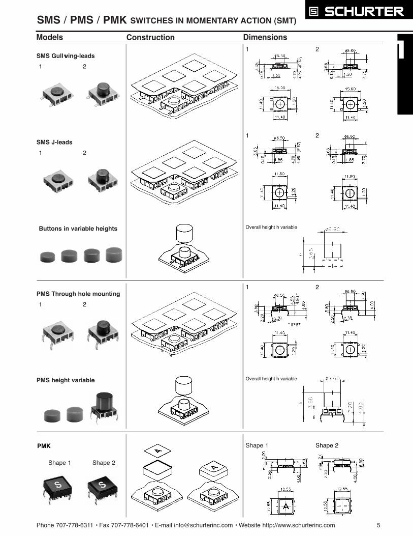
SMS / PMS / PMK SWITCHES IN MOMENTARY ACTION (SMT)
Models
SMS Gullwing-leads
Construction Dimensions
1 2
1 2
SMS J-leads
1 2
PMS height variable
Shape 1 Shape 2
Buttons in variable heights
Shape 1 Shape 2
1 2
1 2
1 2
Overall height h variable
Overall height h variable
PMS Through hole mounting
PMK
6 Phone 707-778-6311 ¥ Fax 707-778-6401 ¥ E-mail [email protected] ¥ Website http://www.schurterinc.com
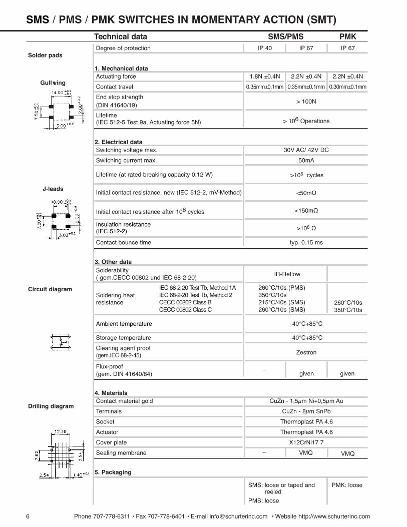
Technical data SMS/PMS PMK
Solder padsDegree of protection
Actuating force1. Mechanical data
IP 40
1.8N ±0.4N 2.2N ±0.4N 2.2N ±0.4N
Contact travel 0.35mm±0.1mm 0.35mm±0.1mm 0.30mm±0.1mm
IP 67 IP 67
End stop strength (DIN 41640/19)
> 100N
(IEC 512-5 Test 9a, Actuating force 5N)Lifetime
> 106 Operations
Switching voltage max.
Switching current max.
30V AC/ 42V DC
50mA
Lifetime (at rated breaking capacity 0.12 W)
Initial contact resistance, new (IEC 512-2, mV-Method) <50m½
Gullwing
Circuit diagram
Drilling diagram
2. Electrical data
>106 cycles
Initial contact resistance after 106 cycles <150m½
>108 ½
Contact bounce time typ. 0.15 ms
( gem.CECC 00802 und IEC 68-2-20)Solderability
IR-Reflow
Soldering heat resistance
3. Other data
5. Packaging
IEC 68-2-20 Test Tb, Method 1AIEC 68-2-20 Test Tb, Method 2CECC 00802 Class BCECC 00802 Class C
260¡C/10s (PMS)350¡C/10s215¡C/40s (SMS)260¡C/10s (SMS)
260¡C/10s 350¡C/10s
-40¡C+85¡C
(gem.IEC 68-2-45)Clearing agent proof
Zestron
Storage temperature -40¡C+85¡C
(gem. DIN 41640/84)Flux-proof _
given given
Contact material gold CuZn - 1,5µm Ni+0,5µm Au
Terminals
Socket Thermoplast PA 4.6
Cover plate X12CrNi17 7
Actuator
Sealing membrane
CuZn - 8µm SnPb
_ VMQ VMQ
Thermoplast PA 4.6
4. Materials
SMS: loose or taped andreeled
PMS: loose
PMK: loose
Insulation resistance (IEC 512-2)
Ambient temperature
J-leads
SMS / PMS / PMK SWITCHES IN MOMENTARY ACTION (SMT)

Phone 707-778-6311 ¥ Fax 707-778-6401 ¥ E-mail [email protected] ¥ Website http://www.schurterinc.com 7
SMS / PMS SWITCHES IN MOMENTARY ACTION
Models Variations select your variation
Degree of protection IP 40
IP 67
1241.1600 .XX
1241.1606 .XX
11
23
Part Number
Packaging
SMSGullwing leads
IP 40
IP 67
1241.1601 .XX
1241.1607 .XX
J- leads
IP 40
IP 67
1241.1612 .XX
1241.1618 .XX
IP 40
IP 67
1241.1613 .XX
1241.1619 .XX
loose in boxes
taped and reeled
Overall height h*8.50 mm
9.25 mm
10.00 mm
10.75 mm
0862.8101
0862.8102
0862.8103
0862.8104
11.50 mm 0862.8105
12.25 mm
13.00 mm
13.75 mm
0862.8106
0862.8107
0862.8108
Button in variable heights for longactuator (must be ordered separately)
Degree of protection IP 40
IP 67
1241.1602
1241.1608
PMSshort actuator
8.35 mm
9.10 mm
9.85 mm
10.60 mm
1
2
3
411.35 mm 5
12.10 mm
12.85 mm13.60 mm
6
7
8
height variable(buttons premounted)
IP 40
IP 67
1241.1614
1241.1620
long actuator
IP 40
IP 67Degree of protection
1241. 1624 .X
1241. 1625 .X
Gullwing leads
J- leads
Overall height h*( yellow )
( orange )
( red )( blue )
( green )
( grey )
( black )( white )
( yellow )
( orange )
( red )
( blue )
( green )
( grey )
( black )( white )
h
h
* Custom button heights up to 19 mm on request.
(700 piece reel = 1241.1600/1601/1606/1607;450 piece reel = 1241.1612/1613/1618/1619)
Models Variations
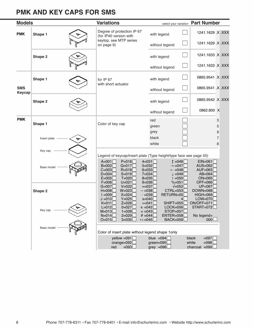
Shape 1
select your variation
Degree of protection IP 67 (for IP40 version withkeytop, see MTP series on page 9)
Color of key capred
green
grey
black
3
5
6
7
Part Number
with legend
without legend
Shape 2 with legend
without legend
for IP 67with short actuator
with legend
without legendSMS Keycap
with legend
without legend
white 8
1241.1629 .X .XXX
1241.1629 .X .XXX
1241.1633 .X .XXX
1241.1633 .X .XXX
0865.9541 .X .XXX
0865.9541 .X .XXX
0865.9542 .X .XXX
0862.800 X
A=001B=002C=003D=004E=005F=006G=007H=008I =009J =010K=011L=012M=013N=014O=015
P=016Q=017R=018S=019T=020U=021V=022W=023X=024Y=025Z=0260=0271=0282=0293=030
4=0315=0326=0337=0348=0359=036+=037
Ð =038á =039x=040Ö=041=042
= =043# =044
=045
=046=047=048=049=050
%=051Ã=052
CTRL=053RETURN=05
4SHIFT=055LOCK=056STOP=057
ENTER=058BACK=059
EIN=061AUS=062AUF=063
AB=064ON=065
OFF=066UP=067
DOWN=068HIGH=069LOW=070
ON/OFF=071START=072
No legend=000
Color of insert plate without legend shape 1only
yellow =091orange=092red =093
blue =094green=095grey =096
black =097white =098charcoal =099
Shape 2
Shape 1
Insert plate
Key cap
Base model
Key cap
Base model
Shape 1
Shape 2
PMK AND KEY CAPS FOR SMS
PMK
PMK
Legend of keycap/insert plate (Type height/type face see page 55)
8 Phone 707-778-6311 ¥ Fax 707-778-6401 ¥ E-mail [email protected] ¥ Website http://www.schurterinc.com

Phone 707-778-6311 ¥ Fax 707-778-6401 ¥ E-mail [email protected] ¥ Website http://www.schurterinc.com 9
MTG / MCS / MTP 1/2Ó SWITCHES IN MOMENTARY ACTION
Models Construction DimensionsMTG 1/2"
MTP 1/2"
MCS 1/2"
Shape 1 Shape 2
Overall height h variable
A S
HIGH
10 Phone 707-778-6311 ¥ Fax 707-778-6401 ¥ E-mail [email protected] ¥ Website http://www.schurterinc.com
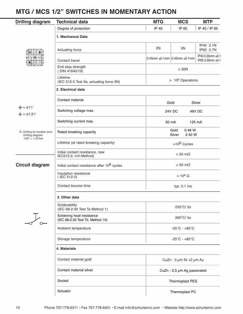
Actuating force 2N 3NIP40 2.1NIP65 2.7N
Drilling diagram Technical data MTG MCS MTP
Contact travel0.45mm ±0.1mm
IP40 0.35mm ±0.1IP65 0.30mm ±0.1
( DIN 41640/19)End stop strength
> 50N
Contact bounce time typ. 0.1 ms
Ambient temperature -25¡C - +85¡C
Contact material gold CuZn - 3 µm Ni +2 µm Au
Storage temperature -25¡C - +85¡C
(IEC 68-2-20 Test Ta Method 1)Solderability 235¡C/ 2s
260¡C/ 5s
( IEC 512-2)Insulation resistance
> 108 ½
Initial contact resistance after 106 cycles < 50 m½
IEC512-2, mV-Method)Initial contact resistance, new < 50 m½
Lifetime (at rated breaking capacity) >106 Cycles
(IEC 512-5 Test 9a, actuating force 5N)Lifetime
> 106 Operations
Contact material
Switching voltage max.
Switching current max.
Gold
24V DC
50 mA 125 mA
48V DC
Silver
(IEC 68-2-20 Test Tb, Method 1A)Soldering heat resistance
CuZn - 2,5 µm Ag passivated
Thermoplast PES
Thermoplast PC
Contact material silver
Socket
Actuator
Circuit diagram
Z= Drilling for location pinsDrilling diagram1/20" = 1.27mm
0.45mm ±0.1mm
1. Mechancal Data
2. Electrical data
4. Materials
3. Other data
= ¿1+0,10
= ¿1.3+0,10
Degree of protection IP 40 IP 65 IP 40 / IP 65
Rated breaking capacity Gold 0.48 WSilver 2.40 W
MTG / MCS 1/2Ó SWITCHES IN MOMENTARY ACTION

Phone 707-778-6311 ¥ Fax 707-778-6401 ¥ E-mail [email protected] ¥ Website http://www.schurterinc.com 11
Models Variations Part NumberMTG 1/2"
short actuator
long actuator
height variable
MCS 1/2"
adhesive sealingpad only on request
select your variation
Ag
Au
Contact material
Ag
Au
Ag
AuContact material
Color of bezelred
green
grey
black
3
5
6
7
8white
1
2
3
4
5
6
7
8
A=001B=002C=003D=004E=005F=006G=007H=008I =009J =010K=011L=012M=013N=014O=015
P=016Q=017R=018S=019T=020U=021V=022W=023X=024Y=025Z=0260=0271=0282=0293=030
4=0315=0326=0337=0348=0359=036+=037
Ð =038á =039x=040Ö=041=042
= =043# =044
=045
=046=047=048=049=050
%=051Ã=052
CTRL=053RETURN=054
SHIFT=055LOCK=056STOP=057
ENTER=058BACK=059LINE=060
EIN=061AUS=062AUF=063
AB=064ON=065
OFF=066UP=067
DOWN=068HIGH=069LOW=070
ON/OFF=071START=072
Legend of face foil (Type height / face see page 55)
yellow =091orange =092red =093
blue =094green=095grey =096
black =097white =098charcoal =099
1241.1072
1241.1022
1241.1082 .X
1241.1032 .X
1241.1053 .X .XXX
1241.1003 .X .XXX
1241.1052
1241.1002
Contact material
Ag
Au
Contact material
MTG / MCS 1/2Ó SWITCHES IN MOMENTARY ACTION
Overall height h*8.50 mm
9.25 mm
10.00 mm
10.75 mm
11.50 mm
12.25 mm
13.00 mm
13.75 mm
( yellow )
( orange )
( red )
( blue )
( green )
( grey )
( black )
( white )
Bezel
Face foil
Base model
Sealing pad(on request)
h
Color of face foil without legend
* Custom button heights up to 19 mm on request.
12 Phone 707-778-6311 ¥ Fax 707-778-6401 ¥ E-mail [email protected] ¥ Website http://www.schurterinc.com
MTP 1/2Ó SWITCHES IN MOMENTARY ACTION
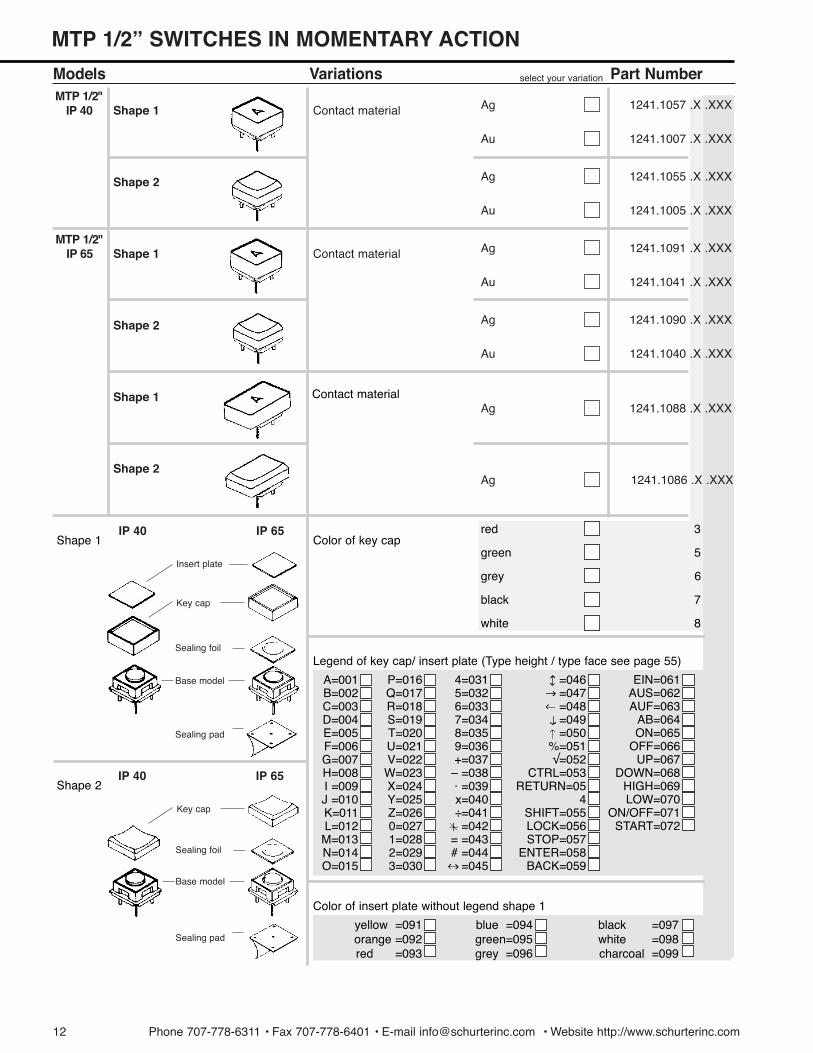
Models VariationsMTP 1/2"
IP 40 Shape 1
select your variation Part Number
Ag
Au
Contact material
Ag
Au
Ag
Ag
Color of key capred
green
grey
black
3
5
6
7
white 8
A=001B=002C=003D=004E=005F=006G=007H=008I =009J =010K=011L=012M=013N=014O=015
P=016Q=017R=018S=019T=020U=021V=022W=023X=024Y=025Z=0260=0271=0282=0293=030
4=0315=0326=0337=0348=0359=036+=037
Ð =038á =039x=040Ö=041=042
= =043# =044
=045
=046=047=048=049=050
%=051Ã=052
CTRL=053RETURN=05
4SHIFT=055LOCK=056STOP=057
ENTER=058BACK=059
EIN=061AUS=062AUF=063
AB=064ON=065
OFF=066UP=067
DOWN=068HIGH=069LOW=070
ON/OFF=071START=072
Legend of key cap/ insert plate (Type height / type face see page 55)
yellow =091orange =092red =093
blue =094green=095grey =096
black =097white =098charcoal =099
Shape 1IP 40 IP 65
1241.1055 .X .XXX
1241.1005 .X .XXX
1241.1091 .X .XXX
1241.1041 .X .XXX
1241.1088 .X .XXX
1241.1086 .X .XXX
1241.1057 .X .XXX
1241.1007 .X .XXX
Shape 2
MTP 1/2"IP 65 Shape 1
Shape 2
Shape 1
Shape 2
Ag
Au
Contact material
Ag
Au
Color of insert plate without legend shape 1
Shape 2IP 40 IP 65
Insert plate
Key cap
Base model
Sealing pad
Sealing foil
Key cap
Base model
Sealing pad
Sealing foil
1241.1090 .X .XXX
1241.1040 .X .XXX
Contact material
Phone 707-778-6311 ¥ Fax 707-778-6401 ¥ E-mail [email protected] ¥ Website http://www.schurterinc.com 13
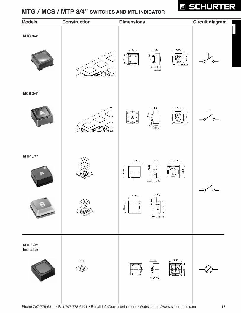
MTG / MCS / MTP 3/4Ó SWITCHES AND MTL INDICATOR
Models Construction Dimensions Circuit diagram
MTG 3/4"
MCS 3/4"
MTP 3/4"
MTL 3/4"Indicator
14 Phone 707-778-6311 ¥ Fax 707-778-6401 ¥ E-mail [email protected] ¥ Website http://www.schurterinc.com
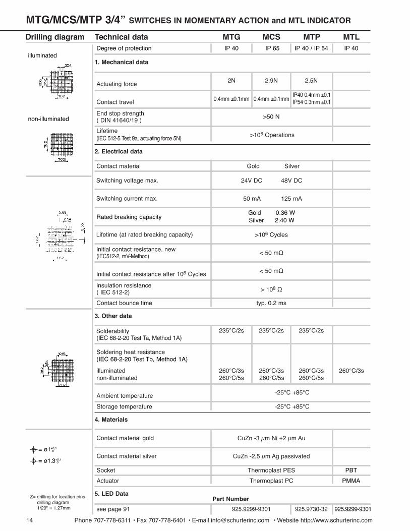
5. LED Data
Technical data
Actuating force
Drilling diagram MTG MCS MTP MTL
2N 2.9N 2.5N
Contact travel
( DIN 41640/19 )End stop strength
0.4mm ±0.1mm 0.4mm ±0.1mmIP40 0.4mm ±0.1IP54 0.3mm ±0.1
>50 N
>106 Operations(IEC 512-5 Test 9a, actuating force 5N)Lifetime
Contact material
Switching voltage max.
Z= drilling for location pinsdrilling diagram1/20" = 1.27mm
Switching current max.
Lifetime (at rated breaking capacity)
(IEC512-2, mV-Method)Initial contact resistance, new
Initial contact resistance after 106 Cycles
( IEC 512-2)Insulation resistance
2. Electrical data
3. Other data
Gold Silver
24V DC 48V DC
50 mA 125 mA
>106 Cycles
< 50 m½
-25¡C +85¡C
-25¡C +85¡C
> 108 ½
typ. 0.2 ms
< 50 m½
Contact bounce time
CuZn -3 µm Ni +2 µm Au
CuZn -2,5 µm Ag passivated
Thermoplast PES
Thermoplast PC
Contact material gold
Contact material silver
Socket
Actuator
Storage temperature
Soldering heat resistance
illuminatednon-illuminated
260¡C/3s260¡C/5s 260¡C/5s 260¡C/5s
260¡C/3s 260¡C/3s 260¡C/3s
4. Materials
1. Mechanical data
(IEC 68-2-20 Test Ta, Method 1A)Solderability 235¡C/2s 235¡C/2s 235¡C/2s
Ambient temperature
see page 91
Degree of protection IP 40 IP 65 IP 40 / IP 54 IP 40
Rated breaking capacityGold 0.36 WSilver 2.40 W
(IEC 68-2-20 Test Tb, Method 1A)
= ¿1+0,10
= ¿1.3+0,10
non-illuminated
illuminated
PBT
PMMA
925.9299-9301
Part Number
925.9299-9301 925.9730-32
MTG/MCS/MTP 3/4Ó SWITCHES IN MOMENTARY ACTION and MTL INDICATOR

Phone 707-778-6311 ¥ Fax 707-778-6401 ¥ E-mail [email protected] ¥ Website http://www.schurterinc.com 15
A=001B=002C=003D=004E=005F=006G=007H=008I =009J =010K=011L=012M=013N=014O=015
P=016Q=017R=018S=019T=020U=021V=022W=023X=024Y=025Z=0260=0271=0282=0293=030
4=0315=0326=0337=0348=0359=036+=037
Ð =038á =039x=040Ö=041=042
= =043# =044
=045
=046=047=048=049=050
%=051Ã=052
CTRL=053RETURN=054
SHIFT=055LOCK=056STOP=057
ENTER=058BACK=059LINE=060
EIN=061AUS=062AUF=063
AB=064ON=065
OFF=066UP=067
DOWN=068HIGH=069LOW=070
ON/OFF=071START=072
Models Variations select your variation
MTG 3/4"non-illuminated
illuminated
Contact material 1241.1117
1241.1118
1241.1132 .X .XXX
1241.1122 .X .XXX
1241.1130 .X .XXX
1241.1120 .X .XXX
1241.1115 .X
1241.1116 .X
Part Number
Ag
Au
Ag
Au
MCS 3/4"non-illuminated
illuminated
Contact material Ag
Au
Ag
Au
Color of bezelred
green
grey
black
3
5
6
7
white
red
green
yellow
8
Legend of insert plate (Type height / type face see page 55)
Color of insert plate without legend
yellow =091orange=092red =093
blue =094green=095grey =096
black =097white =098charcoal =099
Color of LED
transparent, without legend, illuminated
1241.1119 .X .X
MTL 3/4"Indicator
Bezel
Insert plate
Base model
MTG/MCS/MTP 3/4Ó MOMENTARY ACTION and MTL INDICATOR
1
2
3
MCS 3/4"MTL 3/4"
Sealing pad(on request)
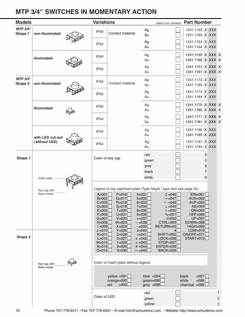
Models VariationsMTP 3/4"
non-illuminated
select your variation Part Number
Shape 1
Insert plate
Key cap withBase model
Color of key capred
green
grey
black
3
5
6
7
white
red
green
yellow
8
A=001B=002C=003D=004E=005F=006G=007H=008I =009J =010K=011L=012M=013N=014O=015
P=016Q=017R=018S=019T=020U=021V=022W=023X=024Y=025Z=0260=0271=0282=0293=030
4=0315=0326=0337=0348=0359=036+=037
Ð =038á =039x=040Ö=041=042
= =043# =044
=045
=046=047=048=049=050
%=051Ã=052
CTRL=053RETURN=05
4SHIFT=055LOCK=056STOP=057
ENTER=058BACK=059
EIN=061AUS=062AUF=063
AB=064ON=065
OFF=066UP=067
DOWN=068HIGH=069LOW=070
ON/OFF=071START=072
yellow =091orange=092red =093
blue =094green=095grey =096
black =097white =098charcoal =099
Color of LED
Contact materialAgAu
AgAu
Shape 1 IP40
IP541241.1154 .X .XXX1241.1164 .X .XXX
1241.1153 .X .XXX1241.1163 .X .XXX
illuminatedAgAu
AgAu
IP40
IP54
MTP 3/4"non-illuminated Contact material
AgAu
AgAu
Shape 2 IP40
IP541241.1174 .X .XXX1241.1184 .X .XXX
1241.1173 .X .XXX1241.1183 .X .XXX
illuminatedAgAu
AgAu
IP40
IP54
with LED cut-out(without LED)
AgAu
AgAu
IP40
IP541241.1191 .X .XXX1241.1194 .X .XXX
1241.1190 .X .XXX
1241.1151 .X .XXX .X1241.1161 .X .XXX .X
1241.1150 .X .XXX .X1241.1160 .X .XXX .X
1241.1171 .X .XXX .X1241.1181 .X .XXX .X
1241.1170 .X .XXX .X1241.1180 .X .XXX .X
MTP 3/4Ó SWITCHES IN MOMENTARY ACTION
1
2
3
Color of insert plate without legend Key cap withBase model
Shape 2
Legend of key cap/insert plate (Type height / type face see page 55)
16 Phone 707-778-6311 ¥ Fax 707-778-6401 ¥ E-mail [email protected] ¥ Website http://www.schurterinc.com
1241.1193 .X .XXX
Phone 707-778-6311 • Fax 707-778-6401 • E-mail [email protected] • Website http://www..schurterinc.com 17
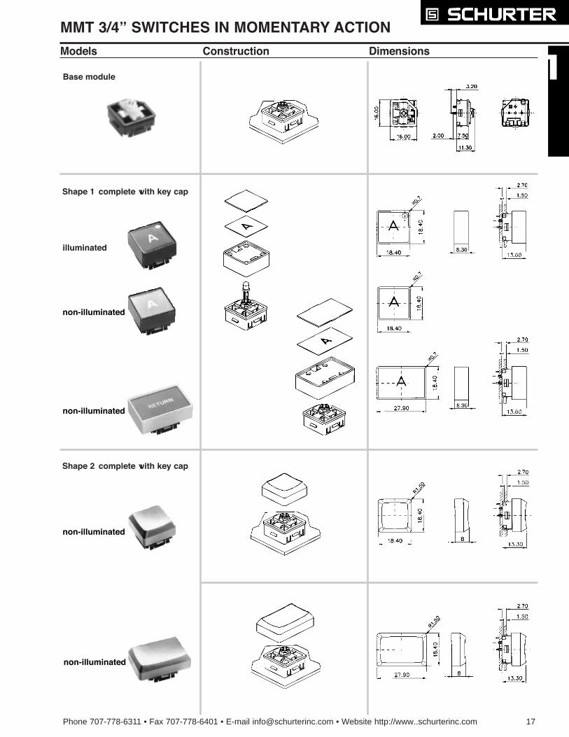
Shape 2 complete with key cap
Shape 1
MMT 3/4Ó SWITCHES IN MOMENTARY ACTION
Models Construction Dimensions
Base module
complete with key cap
illuminated
non-illuminated
non-illuminated
non-illuminated
non-illuminated
18 Phone 707-778-6311 • Fax 707-778-6401 • E-mail [email protected] • Website http://www..schurterinc.com
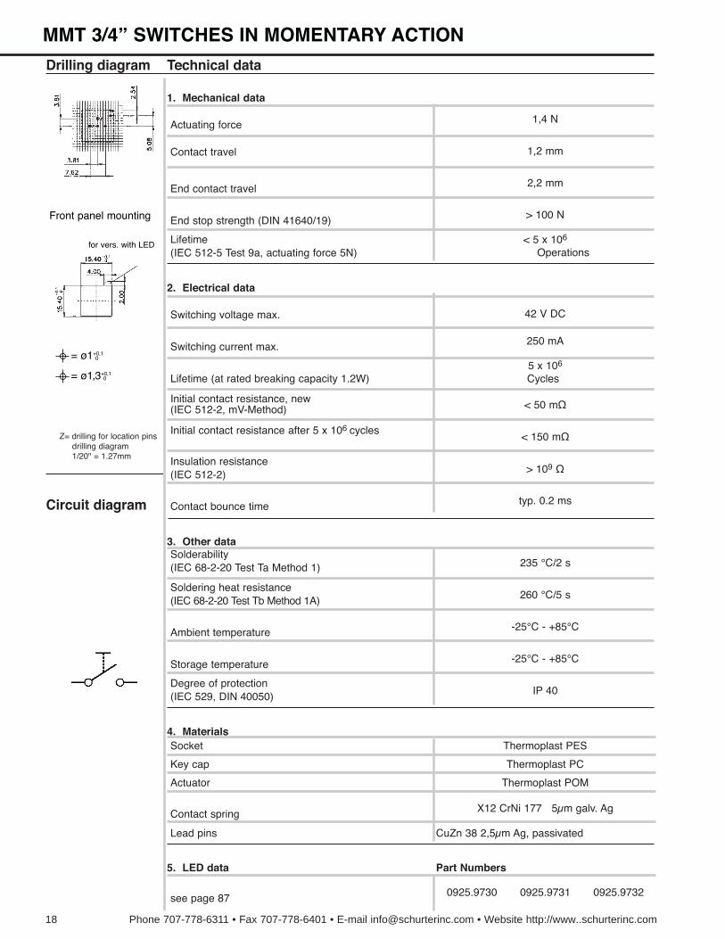
(IEC 512-2)Insulation resistance
> 109 ½
Contact bounce time typ. 0.2 ms
(IEC 68-2-20 Test Tb Method 1A)Soldering heat resistance
260 ¡C/5 s
Ambient temperature -25¡C - +85¡C
(IEC 529, DIN 40050)Degree of protection
IP 40
Socket Thermoplast PES
Key cap Thermoplast PC
Actuator Thermoplast POM
Contact spring X12 CrNi 177 5µm galv. Ag
Lead pins CuZn 38 2,5µm Ag, passivated
(IEC 68-2-20 Test Ta Method 1)Solderability
Storage temperature -25¡C - +85¡C
3. Other data
4. Materials
5. LED data
235 ¡C/2 s
(IEC 512-5 Test 9a, actuating force 5N)Lifetime < 5 x 10⁶
Technical data
Actuating force
Contact travel 1,2 mm
End contact travel
Switching voltage max. 42 V DC
Switching current max. 250 mA
Lifetime (at rated breaking capacity 1.2W)
(IEC 512-2, mV-Method)Initial contact resistance, new < 50 m½
Drilling diagram
Circuit diagram
1,4 N
2,2 mm
End stop strength (DIN 41640/19) > 100 N
Z= drilling for location pinsdrilling diagram1/20" = 1.27mm
Operations
1. Mechanical data
2. Electrical data
see page 87 0925.9730 0925.9731 0925.9732
5 x 10⁶
Cycles
Initial contact resistance after 5 x 10⁶ cycles< 150 m½
= ¿1+0,10
= ¿1,3+0,10
Front panel mounting
for vers. with LED
Part Numbers
MMT 3/4Ó SWITCHES IN MOMENTARY ACTION
Phone 707-778-6311 • Fax 707-778-6401 • E-mail [email protected] • Website http://www..schurterinc.com 19
A=001B=002C=003D=004E=005F=006G=007H=008I =009J =010K=011L=012M=013N=014O=015
P=016Q=017R=018S=019T=020U=021V=022W=023X=024Y=025Z=0260=0271=0282=0293=030
4=0315=0326=0337=0348=0359=036+=037Ð =038á =039x=040Ö=041=042
= =043# =044
=045
=046=047=048=049=050
%=051Ã=052
CTRL=053RETURN=054
SHIFT=055LOCK=056STOP=057
ENTER=058BACK=059LINE=060
EIN=061AUS=062AUF=063
AB=064ON=065
OFF=066UP=067
DOWN=068HIGH=069LOW=070
ON/OFF=071START=072
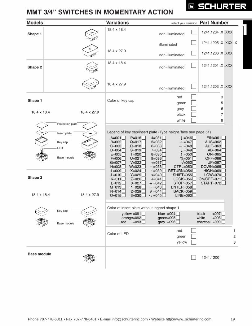
Base module 1241.1200
Models Variations select your variation
Color of key capred
green
grey
black
3
5
6
7
Part Number
white 8
Color of insert plate without legend shape 1
yellow =091orange=092red =093
blue =094green=095grey =096
black =097white =098charcoal =099
Shape 1
18.4 x 18.4non-illuminated
non-illuminated
Shape 1
18.4 x 27.9
18.4 x 18.4non-illuminated
illuminated
18.4 x 27.9non-illuminated
Shape 2 1241.1201 .X .XXX
1241.1203 .X .XXX
1241.1204 .X .XXX
1241.1205 .X .XXX .X
1241.1206 .X .XXX
Color of LEDred
green
yellow
1
2
3
Shape 2
Key cap
Base module
Key cap
Base module
18.4 x 18.4 18.4 x 27.9
MMT 3/4Ó SWITCHES IN MOMENTARY ACTION
Insert plate
Protection plate
LED
18.4 x 18.4 18.4 x 27.9
Legend of key cap/insert plate (Type height / face see page 51)
20 Phone 707-778-6311 • Fax 707-778-6401 • E-mail [email protected] • Website http://www..schurterinc.com
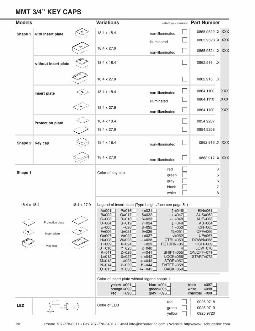
MMT 3/4Ó KEY CAPS
Models Variations select your variation
Color of key capred
green
grey
black
3
5
6
7
Part Number
white 8
A=001B=002C=003D=004E=005F=006G=007H=008I =009J =010K=011L=012M=013N=014O=015
P=016Q=017R=018S=019T=020U=021V=022W=023X=024Y=025Z=0260=0271=0282=0293=030
4=0315=0326=0337=0348=0359=036+=037
Ð =038á =039x=040Ö=041=042
= =043# =044
=045
=046=047=048=049=050
%=051Ã=052
CTRL=053RETURN=05
4SHIFT=055LOCK=056STOP=057
ENTER=058BACK=059
EIN=061AUS=062AUF=063
AB=064ON=065
OFF=066UP=067
DOWN=068HIGH=069LOW=070
ON/OFF=071START=072
Color of insert plate without legend shape 1
yellow =091orange =092red =093
blue =094green=095grey =096
black =097white =098charcoal =099
Shape 1
red
green
yellow
0925.9718
0925.9719
0925.9720
18.4 x 18.4
18.4 x 27.9
0854.9207
0854.9208
Shape 1
0862.916 .X
0862.918 .X
0864.1100 .XXX
0864.1110 .XXX
0864.1120 .XXX
with insert plate
without insert plate
Insert plate
18.4 x 18.4 non-illuminated
illuminated
18.4 x 27.9non-illuminated
0865.9522 .X .XXX
0865.9523 .X .XXX
0865.9524 .X .XXX
18.4 x 18.4
18.4 x 27.9
18.4 x 18.4 non-illuminated
illuminated
18.4 x 27.9non-illuminated
Protection plate
LED
0862.913 .X .XXX
0862.917 .X .XXX
Key cap 18.4 x 18.4 non-illuminated
18.4 x 27.9non-illuminated
Shape 2
18.4 x 18.4 18.4 x 27.9
Protection plate
Insert plate
Key cap
Color of LED
Legend of insert plate (Type height / face see page 51)
Phone 707-778-6311 • Fax 707-778-6401 • E-mail [email protected] • Website http://www.schurterinc.com 21
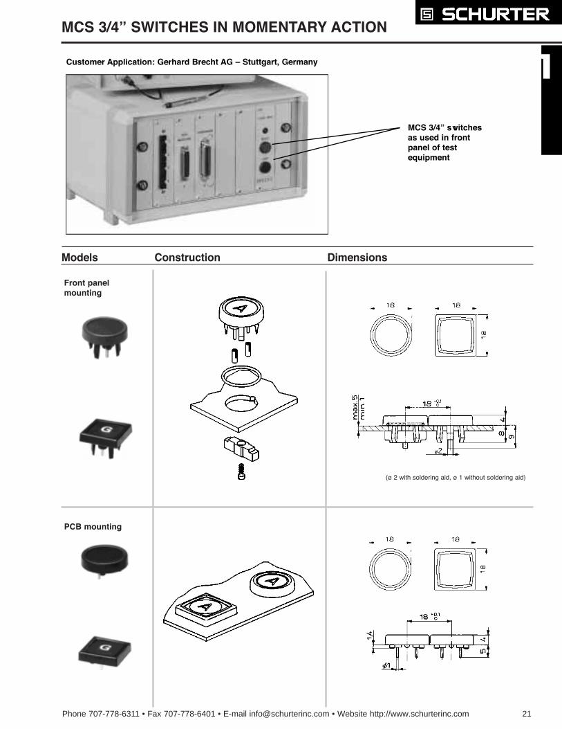
MCS 3/4Ó SWITCHES IN MOMENTARY ACTION
Models Construction Dimensions
Front panelmounting
(¿ 2 with soldering aid, ¿ 1 without soldering aid)
PCB mounting
Customer Application: Gerhard Brecht AG Ð Stuttgart, Germany
MCS 3/4Ó switchesas used in frontpanel of testequipment
22 Phone 707-778-6311 • Fax 707-778-6401 • E-mail [email protected] • Website http://www.schurterinc.com
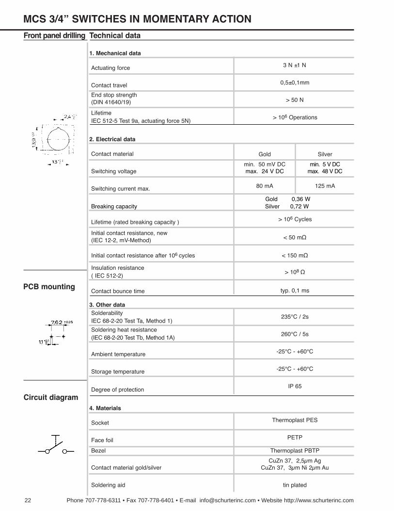
(DIN 41640/19)End stop strength
IEC 512-5 Test 9a, actuating force 5N)Lifetime
Contact material
Switching voltage
Switching current max.
Lifetime (rated breaking capacity )
(IEC 12-2, mV-Method)Initial contact resistance, new
Initial contact resistance after 106 cycles
Technical data
Actuating force
Contact travel 0,5±0,1mm
> 50 N
> 106 Operations
min. 50 mV DC
Gold Silver
Front panel drilling
PCB mounting
Circuit diagram
3 N ±1 N
80 mA 125 mA
> 108 ½
235¡C / 2s
260¡C / 5s
-25¡C - +60¡C
-25¡C - +60¡C
IP 65
Thermoplast PES
PETP
Thermoplast PBTP
CuZn 37, 2,5µm AgCuZn 37, 3µm Ni 2µm Au
typ. 0,1 ms
< 50 m½
< 150 m½
( IEC 512-2)Insulation resistance
Contact bounce time
IEC 68-2-20 Test Ta, Method 1)Solderability
(IEC 68-2-20 Test Tb, Method 1A)Soldering heat resistance
Ambient temperature
Storage temperature
Degree of protection
Socket
Face foil
Bezel
Contact material gold/silver
Soldering aid tin plated
1. Mechanical data
2. Electrical data
3. Other data
4. Materials
> 106 Cycles
max. 24 V DCmin. 5 V DC
max. 48 V DC
Breaking capacityGold 0,36 WSilver 0,72 W
MCS 3/4Ó SWITCHES IN MOMENTARY ACTION
Phone 707-778-6311 • Fax 707-778-6401 • E-mail [email protected] • Website http://www.schurterinc.com 23
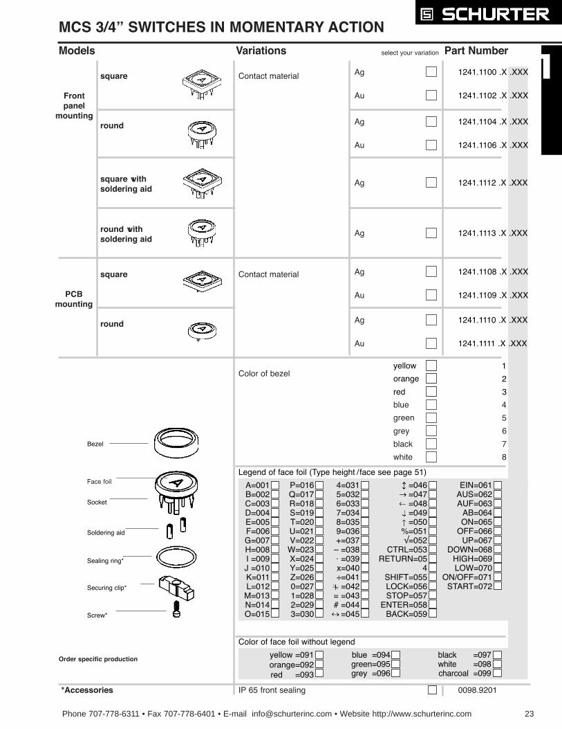
Models Variations select your variation Part Number
Ag
Au
Contact material
Ag
Au
Au
Au
Ag
Ag
Ag
Ag
*Accessories
Color of bezel
blue
green
grey
black
4
5
6
7
white 8
A=001B=002C=003D=004E=005F=006G=007H=008I =009J =010K=011L=012M=013N=014O=015
P=016Q=017R=018S=019T=020U=021V=022W=023X=024Y=025Z=0260=0271=0282=0293=030
4=0315=0326=0337=0348=0359=036+=037
Ð =038á =039x=040Ö=041=042
= =043# =044
=045
=046=047=048=049=050
%=051Ã=052
CTRL=053RETURN=05
4SHIFT=055LOCK=056STOP=057
ENTER=058BACK=059
EIN=061AUS=062AUF=063
AB=064ON=065
OFF=066UP=067
DOWN=068HIGH=069LOW=070
ON/OFF=071START=072
Legend of face foil (Type height / face see page 51)
Color of face foil without legend
yellow =091orange=092red =093
blue =094green=095grey =096
black =097white =098charcoal =099
yellow
orange
red
1
2
3
1241.1104 .X .XXX
1241.1106 .X .XXX
1241.1112 .X .XXX
1241.1108 .X .XXX
1241.1109 .X .XXX
1241.1110 .X .XXX
1241.1111 .X .XXX
1241.1100 .X .XXX
1241.1102 .X .XXX
1241.1113 .X .XXX
square
Frontpanel
mountinground
square withsoldering aid
round withsoldering aid
square
PCBmounting
round
Contact material
IP 65 front sealing 0098.9201
Bezel
Socket
Soldering aid
Sealing ring*
Securing clip*
Screw*
MCS 3/4Ó SWITCHES IN MOMENTARY ACTION
Face foil
Order specific production
24 Phone 707-778-6311 · Fax 707-778-6401 · E-mail [email protected] · Website http://www.schurterinc.com
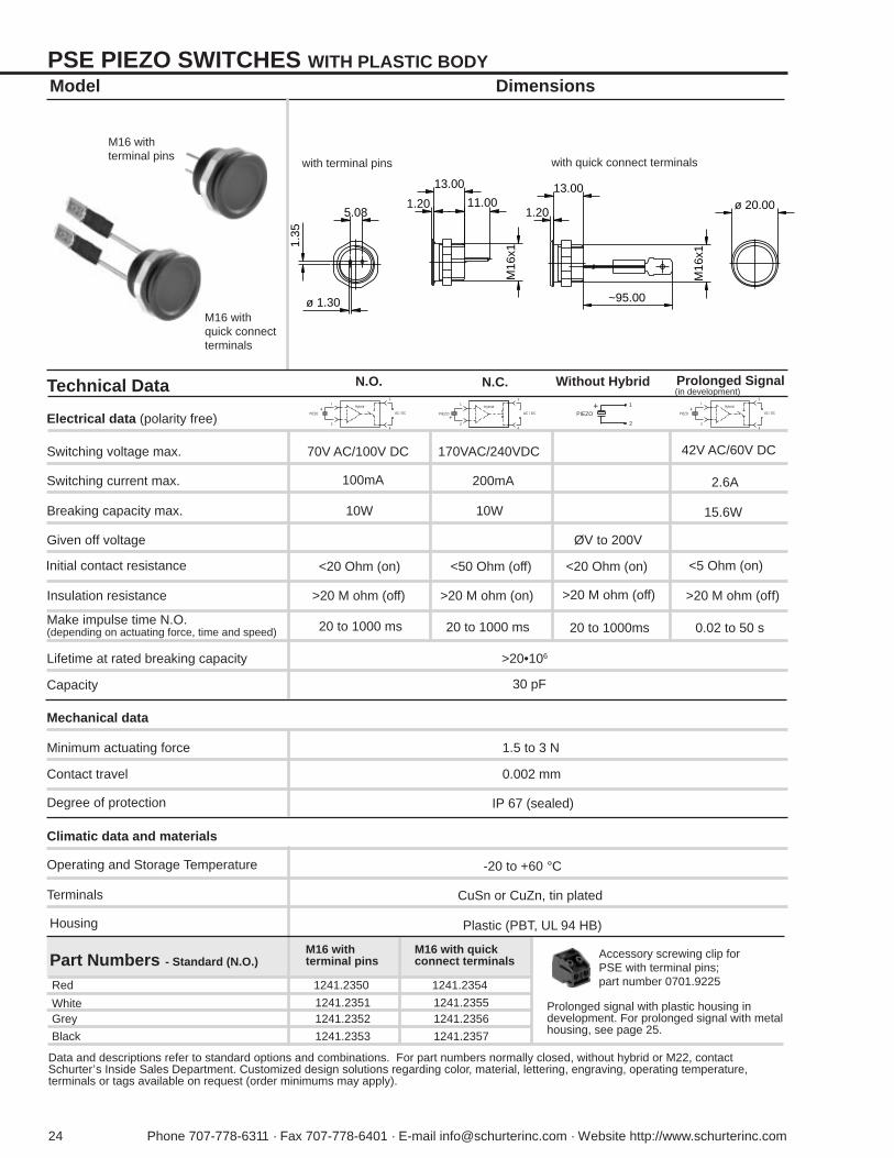
PSE PIEZO SWITCHES WITH PLASTIC BODYDimensionsModel
with terminal pins with quick connect terminals
M16 withterminal pins
M16 withquick connectterminals
1.35
M16
x1
11.00
13.00
5.08
ø 1.30
1.20 ø 20.00
M16
x1
~95.00
13.00
1.20
Part Numbers - Standard (N.O.)
Red
WhiteGrey
Black
1241.2350
1241.23511241.2352
1241.2353
Prolonged signal with plastic housing indevelopment. For prolonged signal with metalhousing, see page 25.
M16 withterminal pins
CuSn or CuZn, tin plated
Plastic (PBT, UL 94 HB)
M16 with quickconnect terminals
1241.2354
1241.23551241.2356
1241.2357
Make impulse time N.O.(depending on actuating force, time and speed)
(in development)Technical Data
Electrical data (polarity free)
N.O. N.C. Without Hybrid Prolonged Signal
Switching voltage max. 70V AC/100V DC
Switching current max. 100mA
Breaking capacity max. 10W
170VAC/240VDC
200mA
10W
Given off voltage ØV to 200V
Initial contact resistance
20 to 1000ms
42V AC/60V DC
2.6A
15.6W
Climatic data and materials
Operating and Storage Temperature -20 to +60 °C
Terminals
Housing
<20 Ohm (on) <50 Ohm (off) <20 Ohm (on) <5 Ohm (on)
20 to 1000 ms 0.02 to 50 s
Mechanical data
Minimum actuating force
0.002 mm
Degree of protection
1.5 to 3 N
Contact travel
IP 67 (sealed)
Lifetime at rated breaking capacity
Insulation resistance
Capacity
>20•106
>20 M ohm (off)
30 pF
20 to 1000 ms
Accessory screwing clip forPSE with terminal pins;part number 0701.9225
Data and descriptions refer to standard options and combinations. For part numbers normally closed, without hybrid or M22, contactSchurter’s Inside Sales Department. Customized design solutions regarding color, material, lettering, engraving, operating temperature,terminals or tags available on request (order minimums may apply).
>20 M ohm (on) >20 M ohm (off) >20 M ohm (off)
Hybrid
31
24
PIEZO+
AC / DC
Hybrid
31
24
PIEZO+
AC / DC
1
2
PIEZO+ Hybrid
31
24
PIEZO+
AC / DC
Phone 707-778-6311 · Fax 707-778-6401 · E-mail [email protected] · Website http://www.schurterinc.com 25
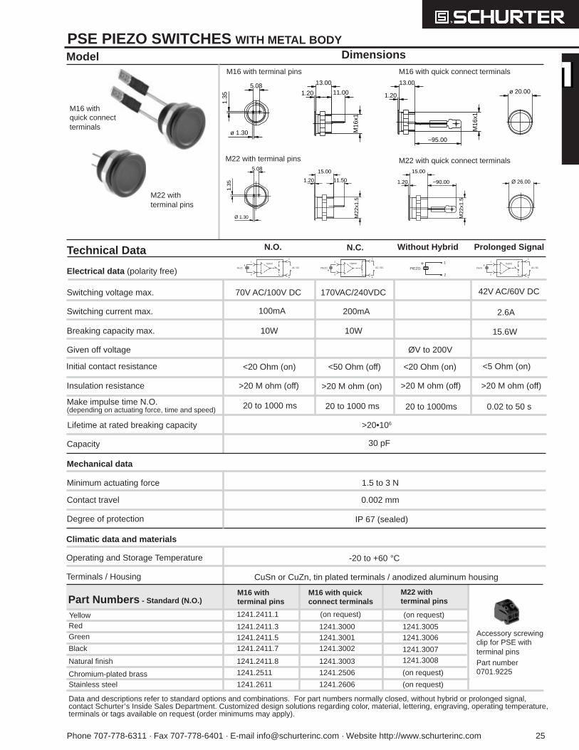
PSE PIEZO SWITCHES WITH METAL BODYDimensionsModel
M16 withquick connectterminals
M16 with terminal pins M16 with quick connect terminals
M22 with terminal pins M22 with quick connect terminals
M22 withterminal pins
1.35
5.08
ø 1.30 M16
x1
~95.00
13.00
1.20
M16
x1
11.00
13.00
1.20 ø 20.00
5.08
1.35
Ø 1.30
1.20 11.50
M22
x1.5
15.00
1.20
M22
x1.5
~90.00
15.00
Ø 26.00
Part Numbers - Standard (N.O.)
1241.2411.1
Red
Black
Green
Natural finish
1241.3000
1241.30021241.3001
1241.3003
M16 withterminal pins
M16 with quickconnect terminals
M22 withterminal pins
1241.30051241.3006
1241.30071241.3008
1241.2411.31241.2411.51241.2411.7
1241.2411.8
(on request) (on request)Yellow
1241.2506 (on request)1241.2511
1241.2606 (on request)1241.2611Chromium-plated brassStainless steel
CuSn or CuZn, tin plated terminals / anodized aluminum housing
Technical Data
Electrical data (polarity free)
N.O. N.C. Without Hybrid Prolonged Signal
Climatic data and materials
Operating and Storage Temperature -20 to +60 °C
Terminals / Housing
Mechanical data
Minimum actuating force
0.002 mm
Degree of protection
1.5 to 3 N
Contact travel
IP 67 (sealed)
Capacity 30 pF
Accessory screwingclip for PSE withterminal pinsPart number0701.9225
Data and descriptions refer to standard options and combinations. For part numbers normally closed, without hybrid or prolonged signal,contact Schurter’s Inside Sales Department. Customized design solutions regarding color, material, lettering, engraving, operating temperature,terminals or tags available on request (order minimums may apply).
Make impulse time N.O.(depending on actuating force, time and speed)
Switching voltage max. 70V AC/100V DC
Switching current max. 100mA
Breaking capacity max. 10W
170VAC/240VDC
200mA
10W
Given off voltage ØV to 200V
Initial contact resistance
20 to 1000ms
42V AC/60V DC
2.6A
15.6W
<20 Ohm (on) <50 Ohm (off) <20 Ohm (on) <5 Ohm (on)
20 to 1000 ms 0.02 to 50 s
Lifetime at rated breaking capacity
Insulation resistance
>20•106
>20 M ohm (off)
20 to 1000 ms
>20 M ohm (on) >20 M ohm (off) >20 M ohm (off)
Hybrid
31
24
PIEZO+
AC / DC
Hybrid
31
24
PIEZO+
AC / DC
1
2
PIEZO+ Hybrid
31
24
PIEZO+
AC / DC
26 Phone 707-778-6311 · Fax 707-778-6401 · E-mail [email protected] · Website http://www.schurterinc.com
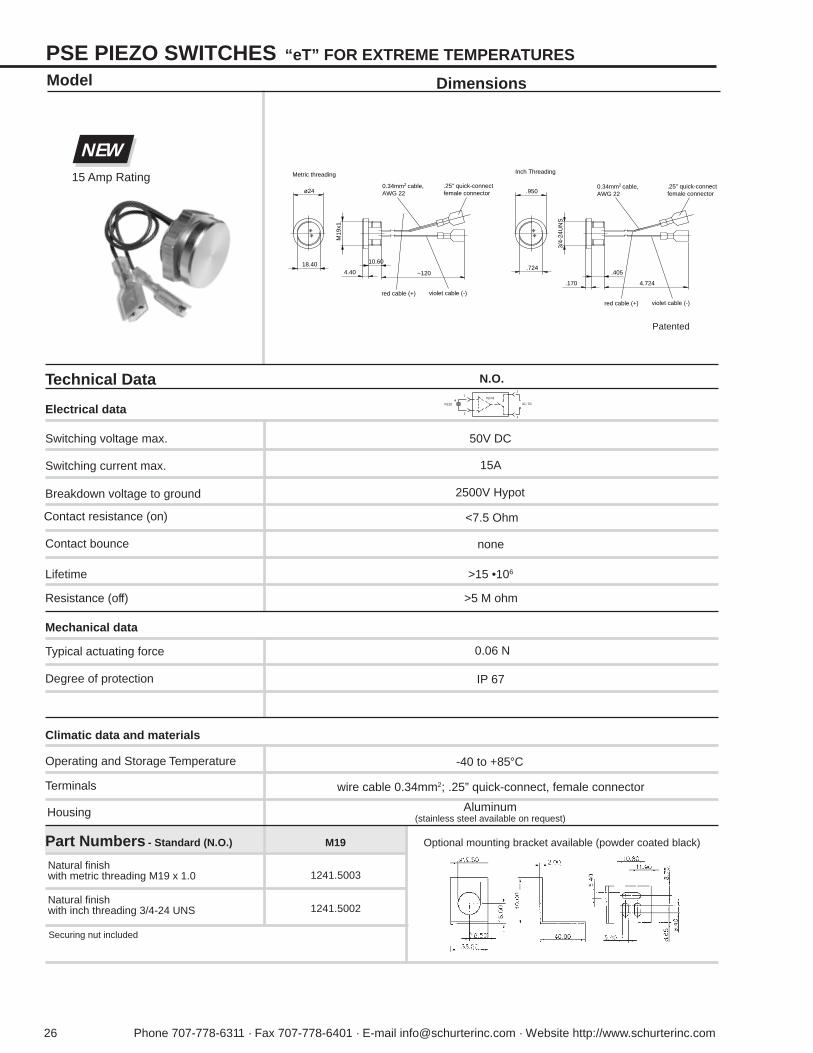
PSE PIEZO SWITCHES “eT” FOR EXTREME TEMPERATURES
Dimensions
Technical Data
Electrical data
N.O.
Switching voltage max. 50V DC
Switching current max. 15A
Breakdown voltage to ground
Contact resistance (on)
Contact bounce
Climatic data and materials
Operating and Storage Temperature -40 to +85°C
Part Numbers - Standard (N.O.)
1241.5002
1241.5003
M19
Terminals wire cable 0.34mm2; .25” quick-connect, female connector
Housing Aluminum(stainless steel available on request)
Model
<7.5 Ohm
none
Mechanical data
Typical actuating force
Degree of protection
0.06 N
IP 67
Lifetime
Resistance (off)
>15 •106
>5 M ohm
2500V Hypot
Patented
NEW15 Amp Rating
Natural finishwith metric threading M19 x 1.0
Natural finishwith inch threading 3/4-24 UNS
Securing nut included
Hybrid
31
24
PIEZO+
AC / DC
4.724.170
3/4-
24U
NS
.9500.34mm2 cable, AWG 22
.25" quick-connect female connector
red cable (+) violet cable (-)
.405
Inch Threading
.724
A
ø24
10.60
~1204.40
M19
x1
Metric threading
18.40
A
0.34mm2 cable, AWG 22
.25" quick-connect female connector
red cable (+) violet cable (-)
Optional mounting bracket available (powder coated black)
Phone 707-778-6311 · Fax 707-778-6401 · E-mail [email protected] · Website http://www.schurterinc.com 27
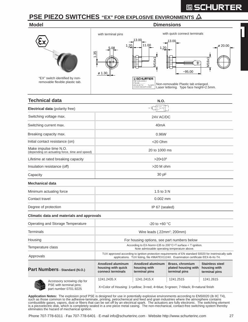
PSE PIEZO SWITCHES “EX” FOR EXPLOSIVE ENVIRONMENTS
Dimensions
Technical data
Electrical data (polarity free)
Model
“EX” switch identified by non-removable flexible plastic tab.
with terminal pins with quick connect terminals
Non-removable Plastic tab enlarged.Laser lettering. Type face height=2.5mm.
PSE 1241.2XX5.XPTB-NR.............EEX ib IIC T4 Tu<60ºCU=24V/I=40mA/P=0.96W
Hybrid
31
24
PIEZO+
1.35
M16
x1
11.00
13.00
5.08
ø 1.30
1.20 ø 20.00
M16
x1
~95.00
13.00
1.20
Part Numbers - Standard (N.O.)
1241.2435.X
Anodized aluminumhousing with quickconnect terminals
Anodized aluminumhousing withterminal pins
Brass, chromiumplated housing withterminal pins
Stainless steelhousing withterminal pins
1241.2415.X 1241.2515 1241.2615
Application Notes: The explosion proof PSE is designed for use in potentially explosive environments according to EN50020 (ib IIC T4),such as those common to the adhesive-laminate, printing, petrochemical and feed and grain industries where the atmosphere containscombustible gases, vapors, dust or fibers that can be set off by an electrical spark. The actuators are fully electronic. The switching elementis a piezoelectric disk, which is completely sealed in a one piece metal casing. The non-mechanical, contact-free switching system therebyeliminates the hazard of mechanical ignition.
Temperature classAccording to EX-Norm>135 to 200°C=T surface < T ignition.
Note admissable operating temperature above.
ApprovalsTUV approved according to ignition protection requirements of EN standard 50020 for instrinsically safe
applications. TUV listing, file #96ATEX1124X. Examination certificate EEX-ib-IIc-T4.
Breaking capacity max.
Switching current max. 40mA
0.96W
Wire leads (.22mm2; 200mm)
Make impulse time N.O.(depending on actuating force, time and speed)
Switching voltage max. 24V AC/DC
Initial contact resistance (on)
Climatic data and materials and approvals
Operating and Storage Temperature -20 to +60 °C
Terminals
<20 Ohm
Mechanical data
Minimum actuating force
0.002 mm
Degree of protection
1.5 to 3 N
Contact travel
IP 67 (sealed)
Lifetime at rated breaking capacity
Insulation resistance (off)
Capacity
>20•106
>20 M ohm
30 pF
20 to 1000 ms
For housing options, see part numbers belowHousing
Accessory screwing clip forPSE with terminal pins;part number 0701.9225 X=Color of Housing: 1=yellow; 3=red; 4=blue; 5=green; 7=black; 8=natural finish
N.O.
28 Phone 707-778-6311 · Fax 707-778-6401 · E-mail [email protected] · Website http://www.schurterinc.com
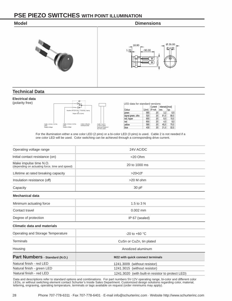
LED data for standard versions
PSE PIEZO SWITCHES WITH POINT ILLUMINATION
Model Dimensions
For the illumination either a one color LED (2 pins) or a bi-color LED (3 pins) is used. Cable 2 is not needed if aone color LED will be used. Color switching can be achieved through a corresponding drive current.
Cable 1 (Color 1 of theLED)Supply voltage
Cable 2 (Color 2 of theLED)Supply voltage
Cable 3 (black):Earth(Ground)
Cable 4 and 5(2-times white)Input and Output ofthe PSE switch
Double-LED (bi-color, 1 housing, 3 pins)or
Single-LED (2 pins)
Ø 4.00
Ø 26.00
1.20
M22
x1.5
~90.00
18.80
CuSn or CuZn, tin plated
Make impulse time N.O.(depending on actuating force, time and speed)
Technical Data
Electrical data(polarity free)
Operating voltage range 24V AC/DC
Initial contact resistance (on)
Climatic data and materials
Operating and Storage Temperature -20 to +60 °C
Terminals
<20 Ohm
Mechanical data
Minimum actuating force
0.002 mm
Degree of protection
1.5 to 3 N
Contact travel
IP 67 (sealed)
Lifetime at rated breaking capacity
Insulation resistance (off)
Capacity
>20•106
>20 M ohm
30 pF
20 to 1000 ms
Anodized aluminumHousing
Part Numbers - Standard (N.O.) M22 with quick connect terminals
Natural finish - red LED 1241.3009 (without resistor)Natural finish - green LED 1241.3015 (without resistor)Natural finish - red LED 1241.3020 (with built-in resistor to protect LED)
Data and descriptions refer to standard options and combinations. For part numbers 5V-12V operating range, bi-color and different colorLEDs, or without switching element contact Schurter’s Inside Sales Department. Customized design solutions regarding color, material,lettering, engraving, operating temperature, terminals or tags available on request (order minimums may apply).
Phone 707-778-6311 · Fax 707-778-6401 · E-mail [email protected] · Website http://www.schurterinc.com 29
LED data for standard versions
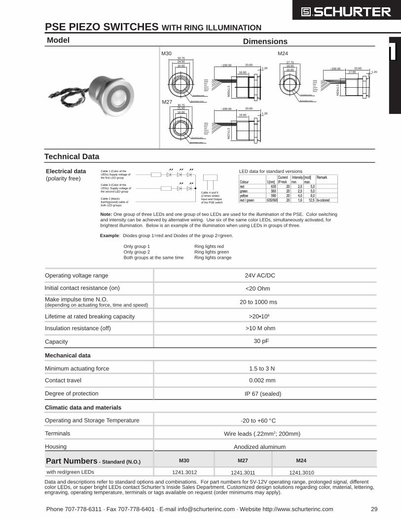
PSE PIEZO SWITCHES WITH RING ILLUMINATION
Model
Technical Data
Electrical data(polarity free)
M30
M27
M24
Note: One group of three LEDs and one group of two LEDs are used for the illumination of the PSE. Color switchingand intensity can be achieved by alternative wiring. Use six of the same color LEDs, simultaneously activated, forbrightest illumination. Below is an example of the illumination when using LEDs in groups of three.
Dimensions
Cable 1 (Color of theLEDs) Supply voltage ofthe first LED group
Cable 3 (Color of theLEDs): Supply voltage ofthe second LED group
Cable 2 (black):Earth(ground) cable ofboth LED groups
Cable 4 and 5(2-times white):Input and Outputof the PSE switch
33.60
16.601.20
33.60
16.60 1.20
M30
x1.5
M27
x1.5
16.00
24.50
16.0021.5030.75
33.75
Actuating area
Illumination area
Actuating area
Illumination area
~200.00
~200.00
whitewhiteblueredgreen
blackyellow
yellowblack
greenredbluewhitewhite
33.6017.60 1.20
M24
x1.5
16.0018.5027.75
Actuating area
Illumination area
~200.00
whitewhiteblueredgreen
blackyellow
Wire leads (.22mm2; 200mm)
Part Numbers - Standard (N.O.) M30 M27 M24
1241.3012 1241.3011 1241.3010with red/green LEDs
Data and descriptions refer to standard options and combinations. For part numbers for 5V-12V operating range, prolonged signal, differentcolor LEDs, or super bright LEDs contact Schurter’s Inside Sales Department. Customized design solutions regarding color, material, lettering,engraving, operating temperature, terminals or tags available on request (order minimums may apply).
Make impulse time N.O.(depending on actuating force, time and speed)
Operating voltage range 24V AC/DC
Initial contact resistance (on)
Climatic data and materials
Operating and Storage Temperature -20 to +60 °C
Terminals
<20 Ohm
Mechanical data
Minimum actuating force
0.002 mm
Degree of protection
1.5 to 3 N
Contact travel
IP 67 (sealed)
Lifetime at rated breaking capacity
Insulation resistance (off)
Capacity
>20•106
>10 M ohm
30 pF
20 to 1000 ms
Anodized aluminumHousing
Example : Diodes group 1=red and Diodes of the group 2=green.
Only group 1 Ring lights redOnly group 2 Ring lights greenBoth groups at the same time Ring lights orange
30 Phone 707-778-6311 · Fax 707-778-6401 · E-mail [email protected] · Website http://www.schurterinc.com
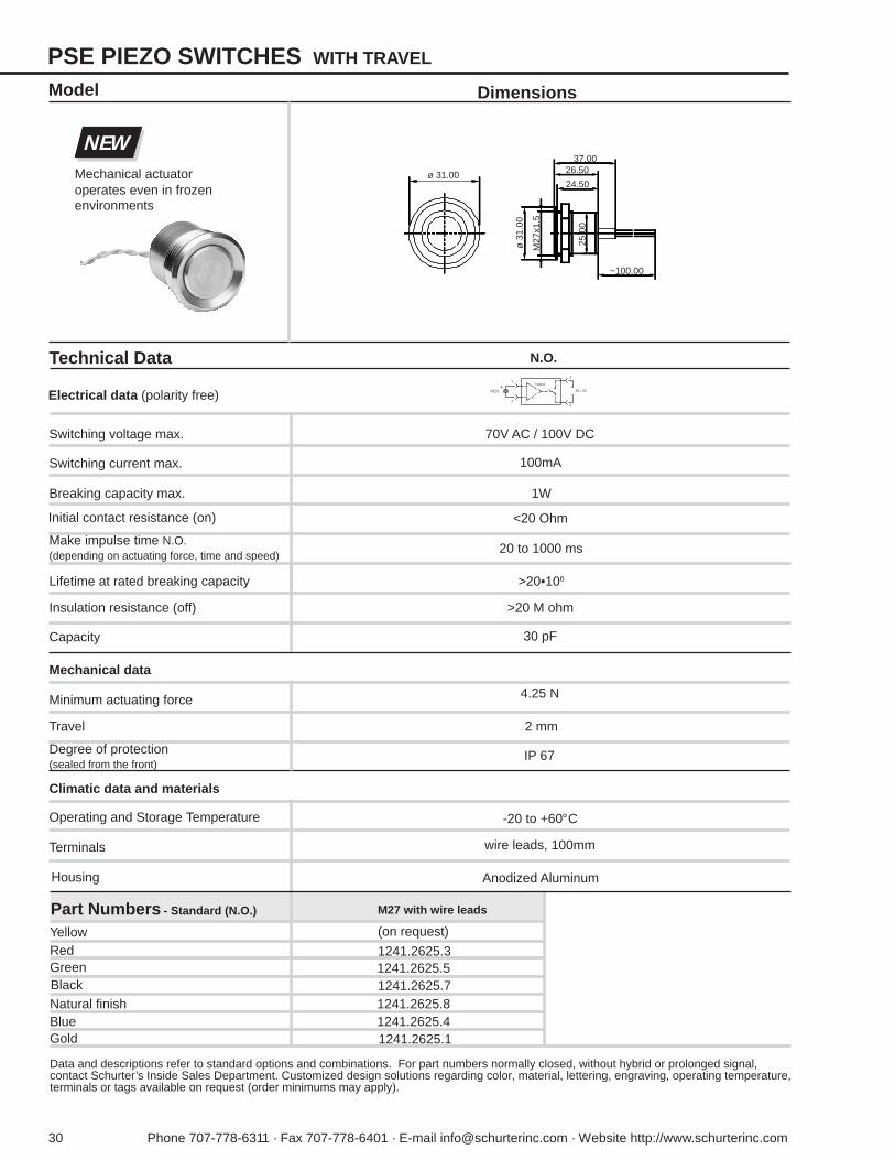
PSE PIEZO SWITCHES WITH TRAVEL
Dimensions
Technical Data
Electrical data (polarity free)
Switching voltage max. 70V AC / 100V DC
Switching current max. 100mA
Breaking capacity max. 1W
Initial contact resistance (on)
Make impulse time N.O.(depending on actuating force, time and speed)
Climatic data and materials
Operating and Storage Temperature -20 to +60°C
Terminals wire leads, 100mm
Housing Anodized Aluminum
Model
<20 Ohm
20 to 1000 ms
Mechanical actuatoroperates even in frozenenvironments
Mechanical data
Minimum actuating force
2 mm
Degree of protection(sealed from the front)
4.25 N
Travel
IP 67
Lifetime at rated breaking capacity
Insulation resistance (off)
Capacity
>20•106
>20 M ohm
30 pF
NEW
Data and descriptions refer to standard options and combinations. For part numbers normally closed, without hybrid or prolonged signal,contact Schurter’s Inside Sales Department. Customized design solutions regarding color, material, lettering, engraving, operating temperature,terminals or tags available on request (order minimums may apply).
Part Numbers - Standard (N.O.)
Red
BlackGreen
Natural finish
1241.2625.3
1241.2625.71241.2625.5
1241.2625.8
M27 with wire leads
(on request)Yellow
1241.2625.41241.2625.1
BlueGold
N.O.
Hybrid
31
24
PIEZO+
AC / DC
37.0026.50
24.50
~100.00
ø 3
1.00
M27
x1.5
25.0
0
ø 31.00
Phone 707-778-6311 • Fax 707-778-6401 • E-mail [email protected] • Website http://www.schurterinc.com 31
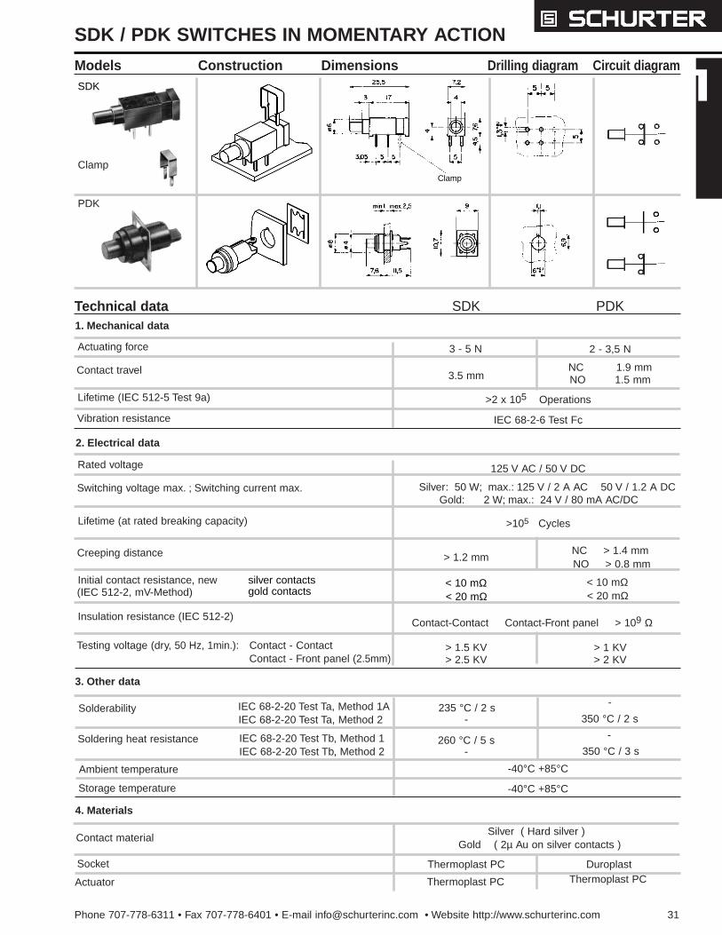
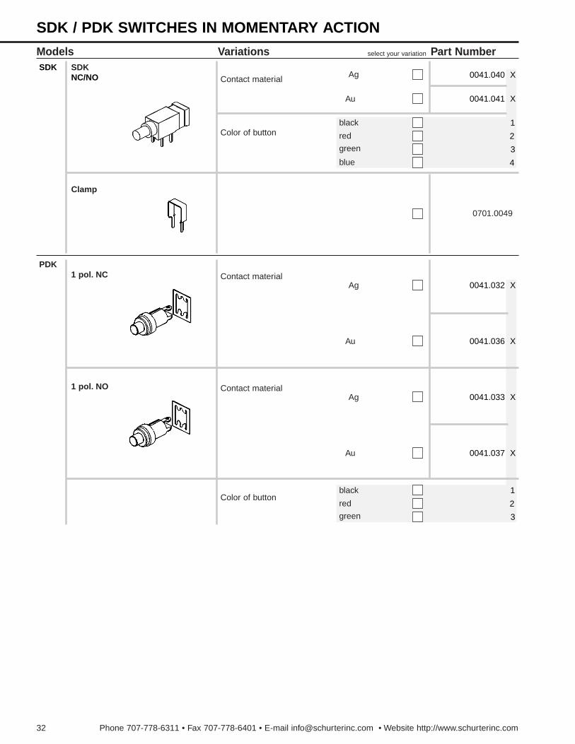
SDK / PDK SWITCHES IN MOMENTARY ACTION
Models Construction Dimensions Drilling diagram Circuit diagram
ClampClamp
SDK
Technical data
PDK
Actuating force
Contact travel
Lifetime (IEC 512-5 Test 9a)
3 - 5 N 2 - 3,5 N
3.5 mmNC 1.9 mm
>2 x 10⁵ Operations
NO 1.5 mm
Vibration resistance IEC 68-2-6 Test Fc
SDK PDK
Rated voltage 125 V AC / 50 V DC
Silver: 50 W; max.: 125 V / 2 A AC 50 V / 1.2 A DC
>105 Cycles
Creeping distance NC > 1.4 mm
Initial contact resistance, new (IEC 512-2, mV-Method)
< 10 mΩ
Insulation resistance (IEC 512-2)
Testing voltage (dry, 50 Hz, 1min.): > 1.5 KV
Ambient temperature
Soldering heat resistance
Solderability
-40°C +85°C
260 °C / 5 s350 °C / 3 s
235 °C / 2 s
Storage temperature -40°C +85°C
Socket
Contact material
Thermoplast PC Duroplast
Silver ( Hard silver )
Actuator Thermoplast PC Thermoplast PC
Switching voltage max. ; Switching current max.Gold: 2 W; max.: 24 V / 80 mA AC/DC
NO > 0.8 mm
< 20 mΩ
Contact-Contact Contact-Front panel > 109 Ω
> 2.5 KV > 2 KV
> 1.2 mm
350 °C / 2 s
Gold ( 2µ Au on silver contacts )
Contact - ContactContact - Front panel (2.5mm)
> 1 KV
IEC 68-2-20 Test Tb, Method 2IEC 68-2-20 Test Tb, Method 1
IEC 68-2-20 Test Ta, Method 2IEC 68-2-20 Test Ta, Method 1A
1. Mechanical data
2. Electrical data
3. Other data
4. Materials
-
-
-
-
Lifetime (at rated breaking capacity)
silver contactsgold contacts
< 10 mΩ< 20 mΩ
32 Phone 707-778-6311 • Fax 707-778-6401 • E-mail [email protected] • Website http://www.schurterinc.com
Models VariationsSDK
NC/NO
select your variation
Contact material
Color of button
Ag
Au
black
red
green
blue
0041.040 X
0041.041 X
1
2
3
4
Part Number
Clamp
0701.0049
1 pol. NC Contact materialAg
Au
1 pol. NO Contact materialAg
Au
Color of buttonblack
red
green
1
2
3
0041.032 X
0041.036 X
0041.033 X
0041.037 X
SDK
PDK
SDK / PDK SWITCHES IN MOMENTARY ACTION
Phone 707-778-6311 • Fax 707-778-6401 • E-mail [email protected] • Website http://www.schurterinc.com 29
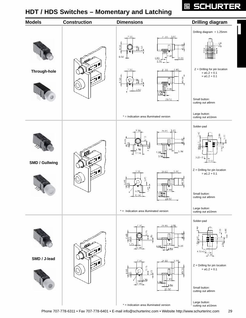
HDT / HDS Switches – Momentary and Latching
Models Construction Dimensions Drilling diagram
Drilling diagram = 1.25mm
Z = Drilling for pin location
Solder-pad
* = Indication area illuminated version
* = Indication area illuminated version
* = Indication area illuminated version
Small button: cutting out ø8mm
Large button: cutting out ø10mm
Z = Drilling for pin location
Solder-pad
Z = Drilling for pin location
Small button: cutting out ø8mm
Large button: cutting out ø10mm
= ø1.2 + 0.1
= ø1.2 + 0.1= ø1.2 + 0.1
Small button: cutting out ø8mm
Large button: cutting out ø10mm
= ø1.2 + 0.1
SMD / J-lead
SMD / Gullwing
Through-hole

Phone 707-778-6311 • Fax 707-778-6401 • E-mail [email protected] • Website http://www.schurterinc.com 31
Models Variations select your variation Part NumberIP 40
HDT with small button - non-illuminated
Switching functions N.O. 1pole 1241.1 X 01 .X .0 .0
N.O. 2pole
N.C.1pole
N.C./N.O. 1pole
N.C. 2pole
wash proof Switching functions N.O. 1pole
N.O. 2pole
N.C.1pole
N.C./N.O. 1pole
N.C. 2pole
IP 65Switching functions N.O. 1pole
N.O. 2pole
N.C.1pole
N.C./N.O. 1pole
N.C. 2pole
Color of small button red
green
black
3
5
6
7
non-illuminated 0
Terminal types
SMD / Gullwing *
SMD / J-Lead *
7
8
9
Through hole
grey
Small button
1241.1 X 02 .X .0 .0
1241.1 X 03 .X .0 .0
1241.1 X 04 .X .0 .0
1241.1 X 05 .X .0 .0
1241.1 X 06 .X .0 .0
1241.1 X 07 .X .0 .0
1241.1 X 08 .X .0 .0
1241.1 X 09 .X .0 .0
1241.1 X 10 .X .0 .0
1241.1 X 11 .X .0 .0
1241.1 X 12 .X .0 .0
1241.1 X 13 .X .0 .0
1241.1 X 14 .X .0 .0
1241.1 X 15 .X .0 .0
Carrier ring
Socket
A B C
A
B
C
Momentaryaction
No large button 0
* SMD types available intrays for auto insertion;on request
Click here for technical information
32 Phone 707-778-6311 • Fax 707-778-6401 • E-mail [email protected] • Website http://www.schurterinc.com
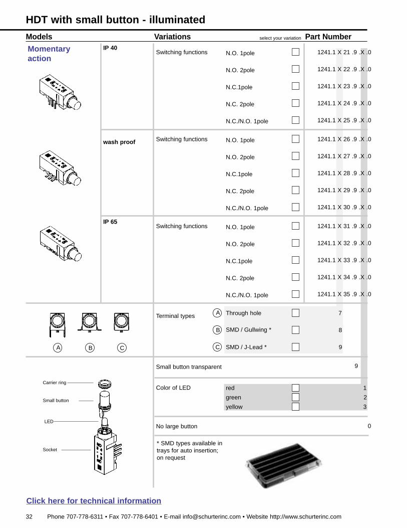
Models Variations select your variation Part NumberIP 40
Switching functions N.O. 1pole 1241.1 X 21 .9 .X .0
N.O. 2pole
N.C.1pole
N.C./N.O. 1pole
N.C. 2pole
wash proof Switching functions N.O. 1pole
N.O. 2pole
N.C.1pole
N.C./N.O. 1pole
N.C. 2pole
IP 65Switching functions N.O. 1pole
N.O. 2pole
N.C.1pole
N.C./N.O. 1pole
N.C. 2pole
Terminal types
SMD / Gullwing *
SMD / J-Lead *
7
8
9
Through hole
1241.1 X 22 .9 .X .0
1241.1 X 23 .9 .X .0
1241.1 X 24 .9 .X .0
1241.1 X 25 .9 .X .0
1241.1 X 26 .9 .X .0
1241.1 X 27 .9 .X .0
1241.1 X 28 .9 .X .0
1241.1 X 29 .9 .X .0
1241.1 X 30 .9 .X .0
1241.1 X 31 .9 .X .0
1241.1 X 32 .9 .X .0
1241.1 X 33 .9 .X .0
1241.1 X 34 .9 .X .0
1241.1 X 35 .9 .X .0
Small button
LED
A B C
A
B
C
Carrier ring
Socket
Momentaryaction
HDT with small button - illuminated
Small button transparent 9
Color of LED red
green
yellow
2
3
No large button 0
* SMD types available intrays for auto insertion;on request
1
Click here for technical information
Phone 707-778-6311 • Fax 707-778-6401 • E-mail [email protected] • Website http://www.schurterinc.com 35
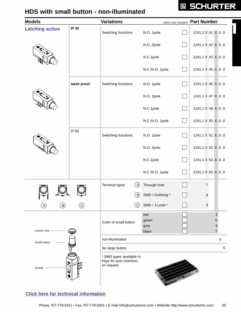
Models Variations select your variation Part NumberIP 40
HDS with small button - non-illuminated
Switching functions N.O. 1pole 1241.1 X 41 .X .0 .0
N.O. 2pole
N.C.1pole
N.C./N.O. 1pole
wash proof Switching functions
IP 65Switching functions
Color of small button
red
green
black
3
5
6
7
non-illuminated 0
Terminal types
SMD / Gullwing *
SMD / J-Lead *
7
8
9
Through hole
grey
Small button
1241.1 X 42 .X .0 .0
1241.1 X 43 .X .0 .0
1241.1 X 45 .X .0 .0
1241.1 X 46 .X .0 .0
1241.1 X 47 .X .0 .0
1241.1 X 48 .X .0 .0
1241.1 X 50 .X .0 .0
1241.1 X 51 .X .0 .0
1241.1 X 52 .X .0 .0
1241.1 X 53 .X .0 .0
1241.1 X 55 .X .0 .0
Carrier ring
Socket
A B C
A
B
C
Latching action
N.O. 1pole
N.O. 2pole
N.C.1pole
N.C./N.O. 1pole
N.O. 1pole
N.O. 2pole
N.C.1pole
N.C./N.O. 1pole
No large button 0
* SMD types available intrays for auto insertion;on request
Click here for technical information
36 Phone 707-778-6311 • Fax 707-778-6401 • E-mail [email protected] • Website http://www.schurterinc.com
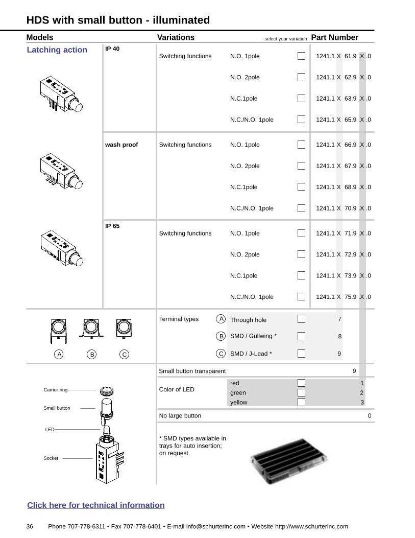
Models Variations select your variation Part NumberIP 40
1241.1 X 61.9 .X .0
wash proof
IP 65
Small button transparent 9
Color of LEDred
green
yellow
1
2
3
Terminal types
SMD / Gullwing *
SMD / J-Lead *
7
8
9
Through hole
1241.1 X 62.9 .X .0
1241.1 X 63.9 .X .0
1241.1 X 65.9 .X .0
1241.1 X 66.9 .X .0
1241.1 X 67.9 .X .0
1241.1 X 68.9 .X .0
1241.1 X 70.9 .X .0
1241.1 X 71.9 .X .0
1241.1 X 72.9 .X .0
1241.1 X 73.9 .X .0
1241.1 X 75.9 .X .0
No large button 0Small button
LED
A B C
A
B
C
Carrier ring
Socket
Latching actionSwitching functions N.O. 1pole
N.O. 2pole
N.C.1pole
N.C./N.O. 1pole
Switching functions
Switching functions
N.O. 1pole
N.O. 2pole
N.C.1pole
N.C./N.O. 1pole
N.O. 1pole
N.O. 2pole
N.C.1pole
N.C./N.O. 1pole
HDS with small button - illuminated
* SMD types available intrays for auto insertion;on request
Click here for technical information

Phone 707-778-6311 • Fax 707-778-6401 • E-mail [email protected] • Website http://www.schurterinc.com 33
non-illuminated 0
Models Variations select your variation Part NumberIP 40
HDT with large button - non-illuminated
Switching functions N.O. 1pole 1241.2 X 01 .X .0 .X
N.O. 2pole
N.C.1pole
N.C./N.O. 1pole
N.C. 2pole
wash proof Switching functions N.O. 1pole
N.O. 2pole
N.C.1pole
N.C./N.O. 1pole
N.C. 2pole
IP 65Switching functions N.O. 1pole
N.O. 2pole
N.C.1pole
N.C./N.O. 1pole
N.C. 2pole
Color of large button
red
green
black
5
6
7
Color of small button
red
green
black
3
5
6
7
Terminal types
SMD / Gullwing *
SMD / J-Lead *
0
1
2
Through hole
grey
grey
Large button
1241.2 X 02 .X .0 .X
1241.2 X 03 .X .0 .X
1241.2 X 04 .X .0 .X
1241.2 X 05 .X .0 .X
1241.2 X 06 .X .0 .X
1241.2 X 07 .X .0 .X
1241.2 X 08 .X .0 .X
1241.2 X 09 .X .0 .X
1241.2 X 10 .X .0 .X
1241.2 X 11 .X .0 .X
1241.2 X 12 .X .0 .X
1241.2 X 13 .X .0 .X
1241.2 X 14 .X .0 .X
1241.2 X 15 .X .0 .X
A B C
A
B
C
Small button
Carrier ring
Socket
Momentaryaction
* SMD types available intrays for auto insertion;on request
3
Click here for technical information
34 Phone 707-778-6311 • Fax 707-778-6401 • E-mail [email protected] • Website http://www.schurterinc.com
Small button transparent 9
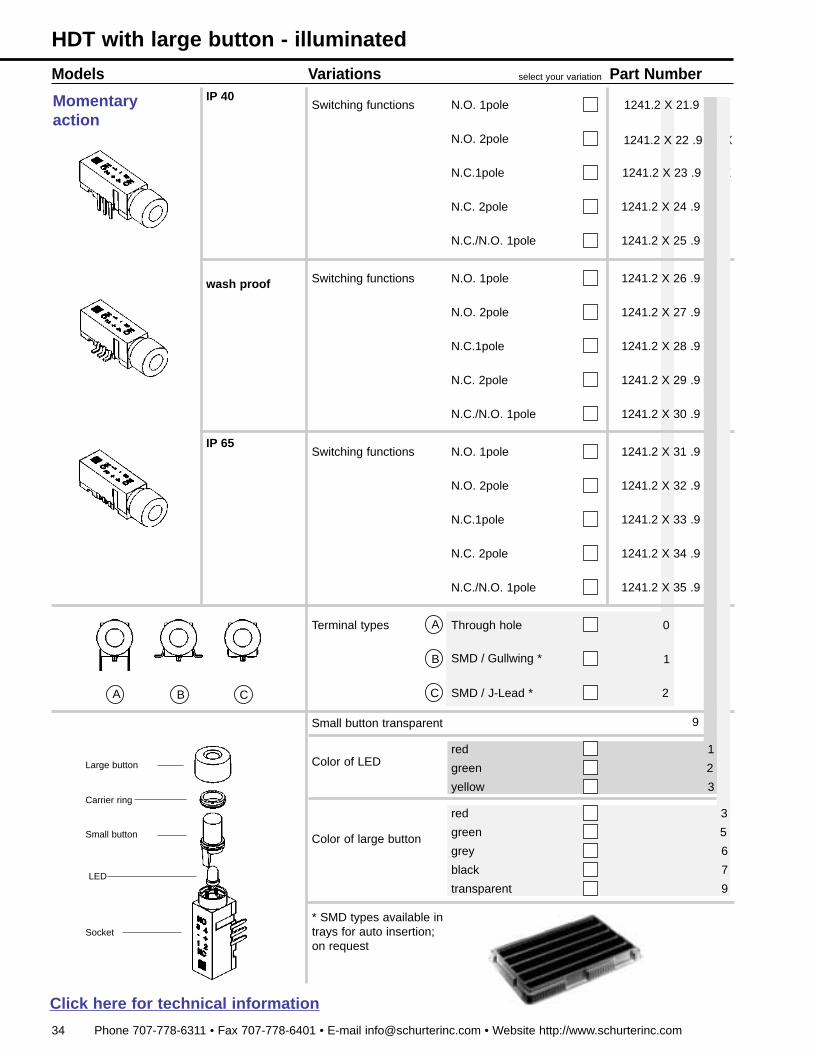
Models Variations select your variation Part NumberIP 40
Switching functions N.O. 1pole 1241.2 X 21.9 .X .X
N.O. 2pole
N.C.1pole
N.C./N.O. 1pole
N.C. 2pole
wash proof Switching functions N.O. 1pole
N.O. 2pole
N.C.1pole
N.C./N.O. 1pole
N.C. 2pole
IP 65Switching functions N.O. 1pole
N.O. 2pole
N.C.1pole
N.C./N.O. 1pole
N.C. 2pole
SMD / Gullwing *
SMD / J-Lead *
0
1
2
Through hole
1241.2 X 22 .9 .X .X
1241.2 X 23 .9 .X .X
1241.2 X 24 .9 .X .X
1241.2 X 25 .9 .X .X
1241.2 X 26 .9 .X .X
1241.2 X 27 .9 .X .X
1241.2 X 28 .9 .X .X
1241.2 X 29 .9 .X .X
1241.2 X 30 .9 .X .X
1241.2 X 31 .9 .X .X
1241.2 X 32 .9 .X .X
1241.2 X 33 .9 .X .X
1241.2 X 34 .9 .X .X
1241.2 X 35 .9 .X .X
Terminal types
Large button
A B C
A
B
C
Small button
LED
Carrier ring
Socket
Momentaryaction
HDT with large button - illuminated
Color of large button
red
green
black
5
6
7
transparent 9
Color of LEDred
green
yellow
2
3
grey
1
3
* SMD types available intrays for auto insertion;on request
Click here for technical information
Phone 707-778-6311 • Fax 707-778-6401 • E-mail [email protected] • Website http://www.schurterinc.com 37
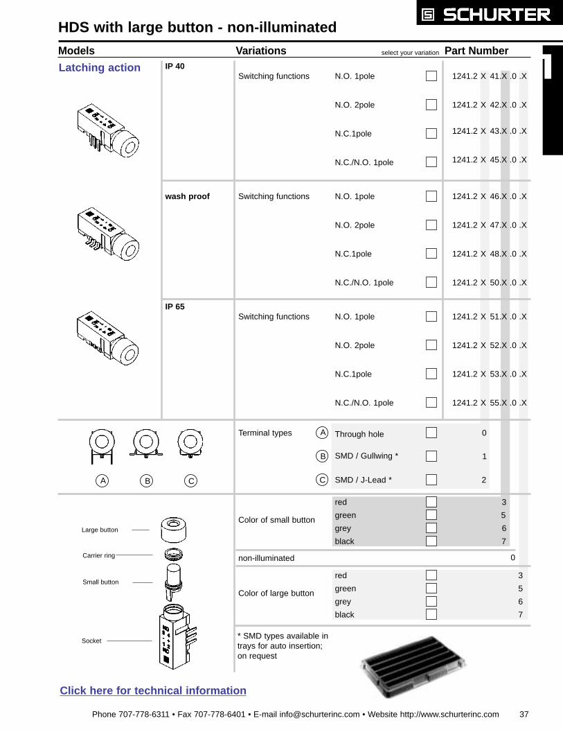
non-illuminated 0
Models Variations select your variation Part NumberIP 40
HDS with large button - non-illuminated
1241.2 X 41.X .0 .X
wash proof
IP 65
Color of large button
red
green
black
5
6
7
Color of small button
red
green
black
3
5
6
7
Terminal types
SMD / Gullwing *
SMD / J-Lead *
0
1
2
Through hole
grey
grey
Large button
1241.2 X 42.X .0 .X
1241.2 X 43.X .0 .X
1241.2 X 45.X .0 .X
1241.2 X 46.X .0 .X
1241.2 X 47.X .0 .X
1241.2 X 48.X .0 .X
1241.2 X 50.X .0 .X
1241.2 X 51.X .0 .X
1241.2 X 52.X .0 .X
1241.2 X 53.X .0 .X
1241.2 X 55.X .0 .X
A B C
A
B
C
Small button
Carrier ring
Socket
Latching actionSwitching functions N.O. 1pole
N.O. 2pole
N.C.1pole
N.C./N.O. 1pole
Switching functions
Switching functions
N.O. 1pole
N.O. 2pole
N.C.1pole
N.C./N.O. 1pole
N.O. 1pole
N.O. 2pole
N.C.1pole
N.C./N.O. 1pole
* SMD types available intrays for auto insertion;on request
3
Click here for technical information
38 Phone 707-778-6311 • Fax 707-778-6401 • E-mail [email protected] • Website http://www.schurterinc.com
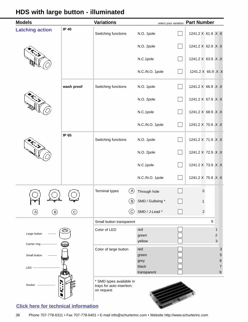
Small button transparent 9
Models Variations select your variation Part NumberIP 40
1241.2 X 61.9 .X .X
wash proof
IP 65
Color of large button red
green
black
5
6
7
transparent 9
Color of LED red
green
yellow
2
3
Terminal types
SMD / Gullwing *
SMD / J-Lead *
0
1
2
Through hole
grey
1241.2 X 62.9 .X .X
1241.2 X 63.9 .X .X
1241.2 X 65.9 .X .X
Large button
A B C
A
B
C
Small button
LED
Carrier ring
Socket
Latching actionSwitching functions N.O. 1pole
N.O. 2pole
N.C.1pole
N.C./N.O. 1pole
Switching functions
Switching functions
N.O. 1pole
N.O. 2pole
N.C.1pole
N.C./N.O. 1pole
N.O. 1pole
N.O. 2pole
N.C.1pole
N.C./N.O. 1pole
1241.2 X 66.9 .X .X
1241.2 X 67.9 .X .X
1241.2 X 68.9 .X .X
1241.2 X 70.9 .X .X
1241.2 X 71.9 .X .X
1241.2 X 72.9 .X .X
1241.2 X 73.9 .X .X
1241.2 X 75.9 .X .X
HDS with large button - illuminated
1
3
* SMD types available intrays for auto insertion;on request
Click here for technical information
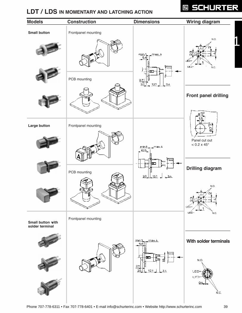
Models Construction Dimensions Wiring diagram
Small button Frontpanel mounting
PCB mounting
Frontpanel mounting
Frontpanel mounting
PCB mounting
Large button
Small button withsolder terminal
Front panel drilling
Drilling diagram
With solder terminals
N.O.
N.C.
Panel cut out< 0.2 x 45¡
N.O.
N.C.
N.O.
N.C.
Phone 707-778-6311 • Fax 707-778-6401 • E-mail [email protected] • Website http://www.schurterinc.com 39
1
LDT / LDS IN MOMENTARY AND LATCHING ACTION
40 Phone 707-778-6311 • Fax 707-778-6401 • E-mail [email protected] • Website http://www.schurterinc.com
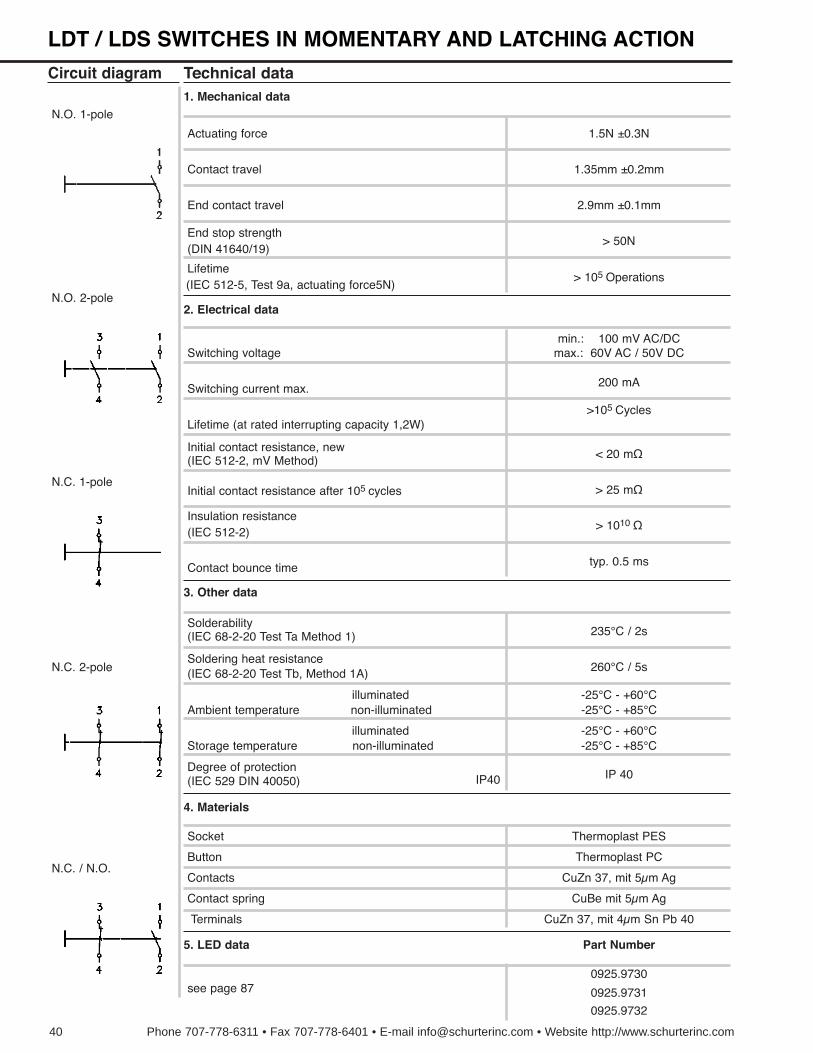
Technical data
Actuating force
Circuit diagram
Switching voltage
Switching current max. 200 mA
Lifetime (at rated interrupting capacity 1,2W)
typ. 0.5 ms
3. Other data
Solderability
(IEC 68-2-20 Test Tb, Method 1A)Soldering heat resistance
(IEC 68-2-20 Test Ta Method 1) 235¡C / 2s
260¡C / 5s
illuminated -25¡C - +60¡C
IP40
4. Materials
Thermoplast PESSocket
N.O. 1-pole
N.O. 2-pole
N.C. 1-pole
N.C. 2-pole
1. Mechanical data
Contact travel
1.5N ±0.3N
1.35mm ±0.2mm
End contact travel 2.9mm ±0.1mm
(DIN 41640/19)End stop strength
> 50N
(IEC 512-5, Test 9a, actuating force5N)Lifetime
2. Electrical data
> 105 Operations
N.C. / N.O.
min.: 100 mV AC/DCmax.: 60V AC / 50V DC
>105 Cycles
(IEC 512-2, mV Method)Initial contact resistance, new
Initial contact resistance after 105 cycles > 25 m½
(IEC 512-2)Insulation resistance
> 1010 ½
< 20 m½
Contact bounce time
Ambient temperature non-illuminated -25¡C - +85¡C
illuminatedStorage temperature non-illuminated
-25¡C - +60¡C-25¡C - +85¡C
(IEC 529 DIN 40050)Degree of protection
IP 40
Button
Contact spring
Contacts
Terminals
Thermoplast PC
CuBe mit 5µm Ag
CuZn 37, mit 5µm Ag
CuZn 37, mit 4µm Sn Pb 40
5. LED data
see page 870925.9730
0925.9731
0925.9732
Part Number
LDT / LDS SWITCHES IN MOMENTARY AND LATCHING ACTION

Phone 707-778-6311 • Fax 707-778-6401 • E-mail [email protected] • Website http://www.schurterinc.com 41
Models Variations select your variation Part Number
LDT / LDS with small button - non-illuminated
Switching functions
Switching functions
N.O. 1pole 0041.9151 .X .X .0 .X
N.O. 2pole
N.C.1pole
N.C./N.O. 1pole
N.C. 2pole
N.O. 1pole
N.O. 2pole
N.C.1pole
N.C./N.O. 1pole
N.C. 2pole
Color of bezel
0850.9242
0850.9277
Securing clip necessaryfor front panel mounting
Module holder optionalfor vertical PCB mounting
1
2
3
Latching action
0041.9152 .X .X .0 .X
0041.9153 .X .X .0 .X
0041.9154 .X .X .0 .X
0041.9155 .X .X .0 .X
0041.9141 .X .X .0 .X
0041.9142 .X .X .0 .X
0041.9143 .X .X .0 .X
0041.9144 .X .X .0 .X
0041.9145 .X .X .0 .X
Momentary action
Color of small button
non-illuminated
Shape of bezeland button
0
blue
green
grey
black
4
5
6
7
white 8
yellow
orange
red
1
2
3
blue
green
grey
black
4
5
6
7
white 8
yellow
orange
red
1
2
3
Mountingaccessories
Small button
Bezel
Holder
1

Models Variations select your variation Part Number
Switching functions
Switching functions
N.O. 1pole 0041.9156 .X .X .X .X
N.O. 2pole
N.C.1pole
N.C./N.O. 1pole
N.C. 2pole
N.O. 1pole
N.O. 2pole
N.C.1pole
N.C./N.O. 1pole
N.C. 2pole
Color of bezel
1
2
3
Latching action
0041.9157 .X .X .X .X
0041.9158 .X .X .X .X
0041.9159 .X .X .X .X
0041.9160 .X .X .X .X
0041.9146 .X .X .X .X
0041.9147 .X .X .X .X
0041.9148 .X .X .X .X
0041.9149 .X .X .X .X
0041.9150 .X .X .X .X
Momentary action
Color of small button
yellow
red
green
1
3
5
Color of LEDred
green
yellow
1
2
3
Shape of bezel andbutton
yellow
orange
red
blue
1
2
3
4
5
6
7
8
green
grey
black
white
0850.9242
0850.9277
Securing clip necessaryfor front panel mounting
Module holder optionalfor vertical PCB mounting
Mountingaccessories
Small button
Bezel
Holder
LED
LDT / LDS with small button - illuminated
42 Phone 707-778-6311 • Fax 707-778-6401 • E-mail [email protected] • Website http://www.schurterinc.com
Phone 707-778-6311 • Fax 707-778-6401 • E-mail [email protected] • Website http://www.schurterinc.com 43
Models Variations select your Part Number
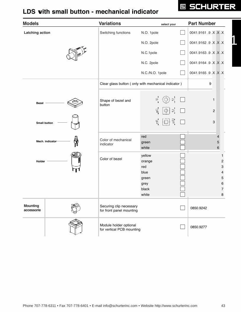
LDS with small button - mechanical indicator
Switching functions N.O. 1pole 0041.9161 .9 .X .X .X
N.O. 2pole
N.C.1pole
N.C./N.O. 1pole
N.C. 2pole
Color of bezel
1
2
3
Latching action
0041.9162 .9 .X .X .X
0041.9163 .9 .X .X .X
0041.9164 .9 .X .X .X
0041.9165 .9 .X .X .X
Color of mechanicalindicator
red
green
white
4
5
6
Shape of bezel andbutton
Clear glass button ( only with mechanical indicator ) 9
yellow
orange
red
blue
1
2
3
4
5
6
7
8
green
grey
black
white
0850.9242
0850.9277
Securing clip necessaryfor front panel mounting
Module holder optionalfor vertical PCB mounting
Mountingaccessorie
Small button
Bezel
Holder
Mech. indicator
1
44 Phone 707-778-6311 • Fax 707-778-6401 • E-mail [email protected] • Website http://www.schurterinc.com
Models Variations select your variation Part Number
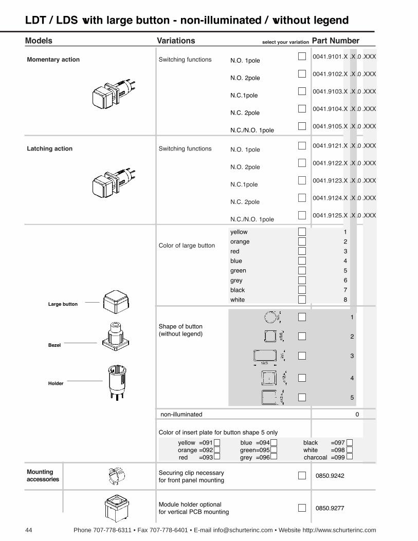
LDT / LDS with large button - non-illuminated / without legend
Switching functions
Switching functions
N.O. 1pole0041.9121.X .X .0 .XXX
N.O. 2pole
N.C.1pole
N.C./N.O. 1pole
N.C. 2pole
N.O. 1pole
N.O. 2pole
N.C.1pole
N.C./N.O. 1pole
N.C. 2pole
Color of insert plate for button shape 5 only
1
2
3
4
5
Latching action
0041.9122.X .X .0 .XXX
0041.9123.X .X .0 .XXX
0041.9124.X .X .0 .XXX
0041.9125.X .X .0 .XXX
0041.9101.X .X .0 .XXX
0041.9102.X .X .0 .XXX
0041.9103.X .X .0 .XXX
0041.9104.X .X .0 .XXX
0041.9105.X .X .0 .XXX
Momentary action
Color of large button
non-illuminated 0
Shape of button(without legend)
yellow =091orange =092red =093
blue =094green=095grey =096
black =097white =098charcoal =099
blue
green
grey
black
white
yellow
orange
red
4
5
6
7
8
1
2
3
0850.9242
0850.9277
Securing clip necessaryfor front panel mounting
Module holder optionalfor vertical PCB mounting
Mountingaccessories
Large button
Bezel
Holder
Phone 707-778-6311 • Fax 707-778-6401 • E-mail [email protected] • Website http://www.schurterinc.com 45
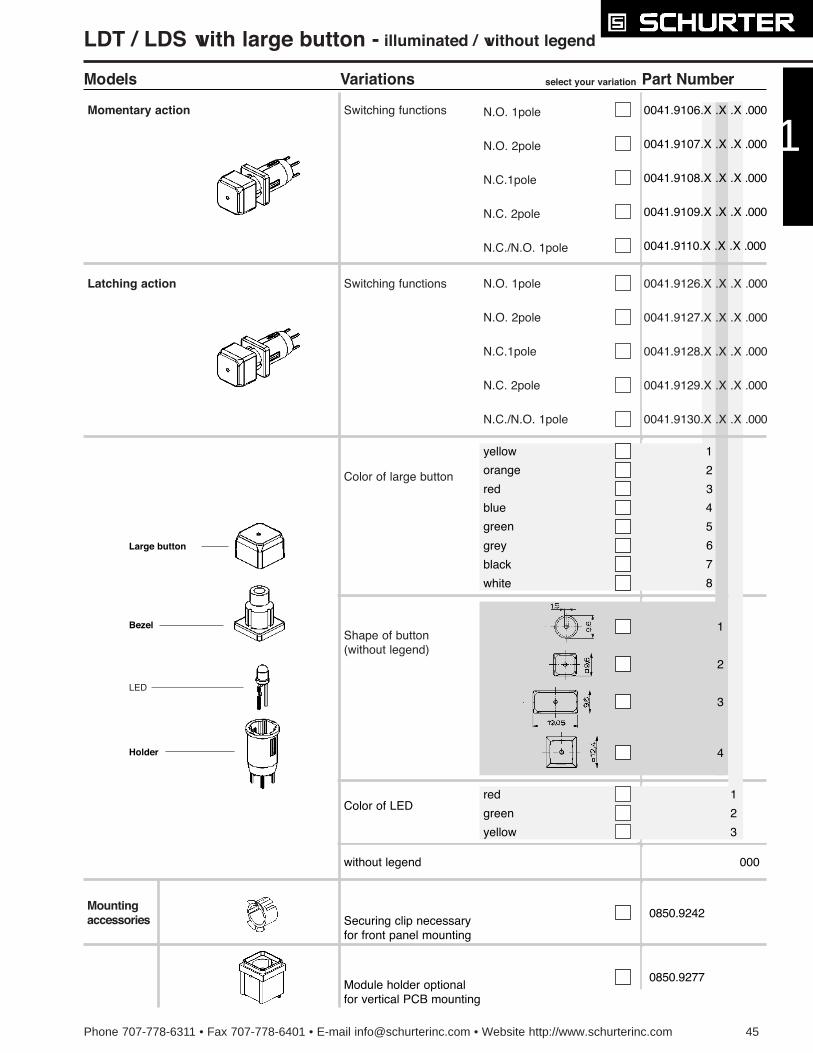
Models Variations select your variation Part Number
Switching functions
Switching functions
N.O. 1pole 0041.9126.X .X .X .000
N.O. 2pole
N.C.1pole
N.C./N.O. 1pole
N.C. 2pole
N.O. 1pole
N.O. 2pole
N.C.1pole
N.C./N.O. 1pole
N.C. 2pole
Color of LED
1
2
3
4
1
2
3
000without legend
Latching action
0041.9127.X .X .X .000
0041.9128.X .X .X .000
0041.9129.X .X .X .000
0041.9130.X .X .X .000
Momentary action
Color of large button
Shape of button(without legend)
blue
green
grey
black
white
yellow
orange
red
green
yellow
red
4
5
6
7
8
1
2
3
0850.9242
0850.9277
Securing clip necessaryfor front panel mounting
Module holder optionalfor vertical PCB mounting
0041.9106.X .X .X .000
0041.9107.X .X .X .000
0041.9108.X .X .X .000
0041.9109.X .X .X .000
0041.9110.X .X .X .000
Mountingaccessories
Large button
Bezel
Holder
LED
1
LDT / LDS with large button - illuminated / without legend
46 Phone 707-778-6311 • Fax 707-778-6401 • E-mail [email protected] • Website http://www.schurterinc.com
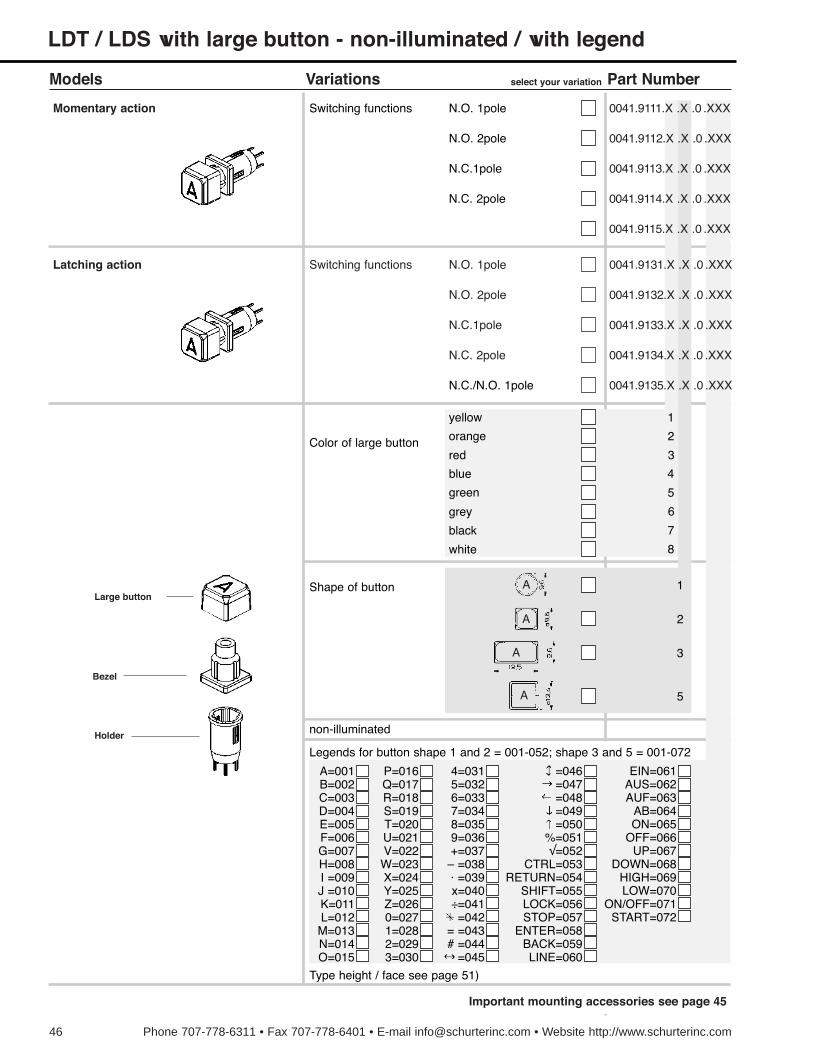
LDT / LDS with large button - non-illuminated / with legend
Models Variations select your variation Part Number
Switching functions N.O. 1pole
N.O. 2pole
N.C.1pole
N.C. 2pole
Latching action 0041.9131.X .X .0 . XXX
0041.9132.X .X .0 . XXX
0041.9133.X .X .0 . XXX
0041.9134.X .X .0 . XXX
0041.9135.X .X .0 . XXX
Switching functions N.O. 1pole
N.O. 2pole
N.C.1pole
N.C./N.O. 1pole
N.C. 2pole
Momentary action 0041.9111.X .X .0 . XXX
0041.9112.X .X .0 . XXX
0041.9113.X .X .0 . XXX
0041.9114.X .X .0 . XXX
0041.9115.X .X .0 . XXX
Color of large button
blue
green
grey
black
white
yellow
orange
red
4
5
6
7
8
1
2
3
Shape of button
non-illuminated
A=001B=002C=003D=004E=005F=006G=007H=008I =009J =010K=011L=012M=013N=014O=015
P=016Q=017R=018S=019T=020U=021V=022W=023X=024Y=025Z=0260=0271=0282=0293=030
4=0315=0326=0337=0348=0359=036+=037
Ð =038á =039x=040Ö=041=042
= =043# =044
=045
=046=047=048=049=050
%=051Ã=052
CTRL=053RETURN=054
SHIFT=055LOCK=056STOP=057
ENTER=058BACK=059LINE=060
EIN=061AUS=062AUF=063
AB=064ON=065
OFF=066UP=067
DOWN=068HIGH=069LOW=070
ON/OFF=071START=072
Legends for button shape 1 and 2 = 001-052; shape 3 and 5 = 001-072
Type height / face see page 51)
Large button
Bezel
Holder
A
A
A
A
1
2
3
5
Important mounting accessories see page 45
Phone 707-778-6311 • Fax 707-778-6401 • E-mail [email protected] • Website http://www.schurterinc.com 47
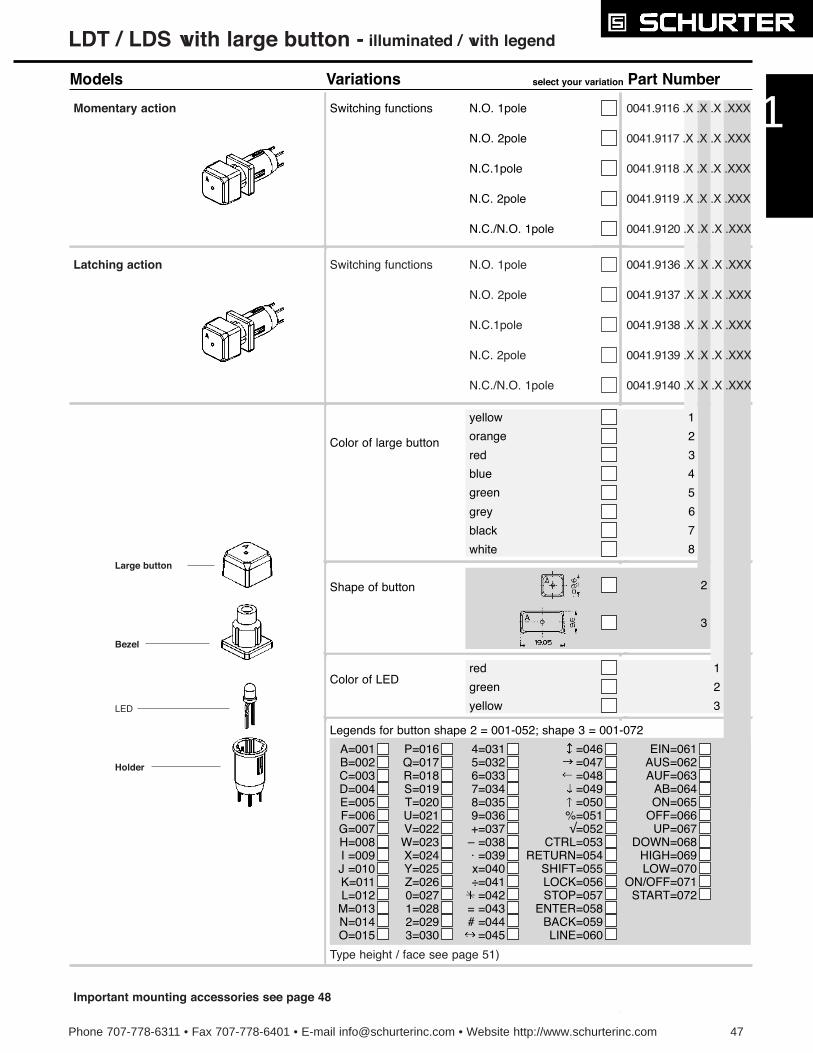
Color of LEDgreen
yellow
red
LDT / LDS with large button - illuminated / with legend
Models Variations select your variation Part Number
Switching functions N.O. 1pole
N.O. 2pole
N.C.1pole
N.C./N.O. 1pole
N.C. 2pole
Latching action 0041.9136 .X .X .X .XXX
0041.9137 .X .X .X .XXX
0041.9138 .X .X .X .XXX
0041.9139 .X .X .X .XXX
0041.9140 .X .X .X .XXX
Switching functions N.O. 1pole
N.O. 2pole
N.C.1pole
N.C./N.O. 1pole
N.C. 2pole
Momentary action 0041.9116 .X .X .X .XXX
0041.9117 .X .X .X .XXX
0041.9118 .X .X .X .XXX
0041.9119 .X .X .X .XXX
0041.9120 .X .X .X .XXX
Color of large button
blue
green
grey
black
white
yellow
orange
red
4
5
6
7
8
1
2
3
2
3
Shape of button
A=001B=002C=003D=004E=005F=006G=007H=008I =009J =010K=011L=012M=013N=014O=015
P=016Q=017R=018S=019T=020U=021V=022W=023X=024Y=025Z=0260=0271=0282=0293=030
4=0315=0326=0337=0348=0359=036+=037
Ð =038á =039x=040Ö=041=042
= =043# =044
=045
=046=047=048=049=050
%=051Ã=052
CTRL=053RETURN=054
SHIFT=055LOCK=056STOP=057
ENTER=058BACK=059LINE=060
EIN=061AUS=062AUF=063
AB=064ON=065
OFF=066UP=067
DOWN=068HIGH=069LOW=070
ON/OFF=071START=072
Legends for button shape 2 = 001-052; shape 3 = 001-072
1
2
3
Important mounting accessories see page 48
Type height / face see page 51)
Large button
Bezel
Holder
LED
1

Models Variations select your variation Part Number
LDT / LDS with small button and solder terminals - non-illuminated
Switching functions
Switching functions
N.O. 1pole 0041.8851.X .X .0 .X
N.O. 2pole
N.C.1pole
N.C./N.O. 1pole
N.C. 2pole
N.O. 1pole
N.O. 2pole
N.C.1pole
N.C./N.O. 1pole
N.C. 2pole
Color of bezel
1
2
3
0
Latching action
0041.8852.X .X .0. X
0041.8853.X .X .0 .X
0041.8854.X .X .0 .X
0041.8855.X .X .0 .X
0041.8841.X .X .0 .X
0041.8842.X .X .0 .X
0041.8843.X .X .0 .X
0041.8844.X .X .0 .X
0041.8845.X .X .0 .X
Momentary action
Color of small button
non-illuminated
Shape of bezeland button
blue
green
grey
black
white
yellow
orange
red
4
5
6
7
8
1
2
3
blue
green
grey
black
white
yellow
orange
red
4
5
6
7
8
1
2
3
Securing clip supplied together withsoldering type
Mountingaccessories
Small button
Bezel
Holder
Securing clip
48 Phone 707-778-6311 • Fax 707-778-6401 • E-mail [email protected] • Website http://www.schurterinc.com
Phone 707-778-6311 • Fax 707-778-6401 • E-mail [email protected] • Website http://www.schurterinc.com 49
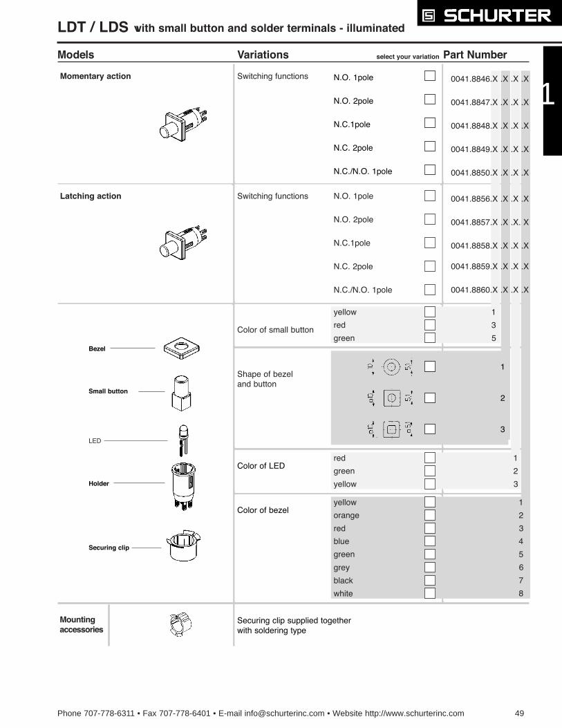
Models Variations select your variation Part Number
Switching functions
Switching functions
N.O. 1pole 0041.8856.X .X .X .X
N.O. 2pole
N.C.1pole
N.C./N.O. 1pole
N.C. 2pole
N.O. 1pole
N.O. 2pole
N.C.1pole
N.C./N.O. 1pole
N.C. 2pole
Color of bezel
1
2
3
Latching action
0041.8857.X .X .X. X
0041.8858.X .X .X .X
0041.8859.X .X .X .X
0041.8860.X .X .X .X
0041.8846.X .X .X .X
0041.8847.X .X .X .X
0041.8848.X .X .X .X
0041.8849.X .X .X .X
0041.8850.X .X .X .X
Momentary action
Color of small button
Shape of bezeland button
yellow
red
green
1
3
5
red
green
yellow
1
2
3
blue
green
grey
black
white
yellow
orange
red
4
5
6
7
8
1
2
3
Securing clip supplied togetherwith soldering type
Color of LED
Mountingaccessories
Small button
Bezel
Holder
Securing clip
LED
1
LDT / LDS with small button and solder terminals - illuminated
50 Phone 707-778-6311 • Fax 707-778-6401 • E-mail [email protected] • Website http://www.schurterinc.com
Models Variations select your variation Part Number
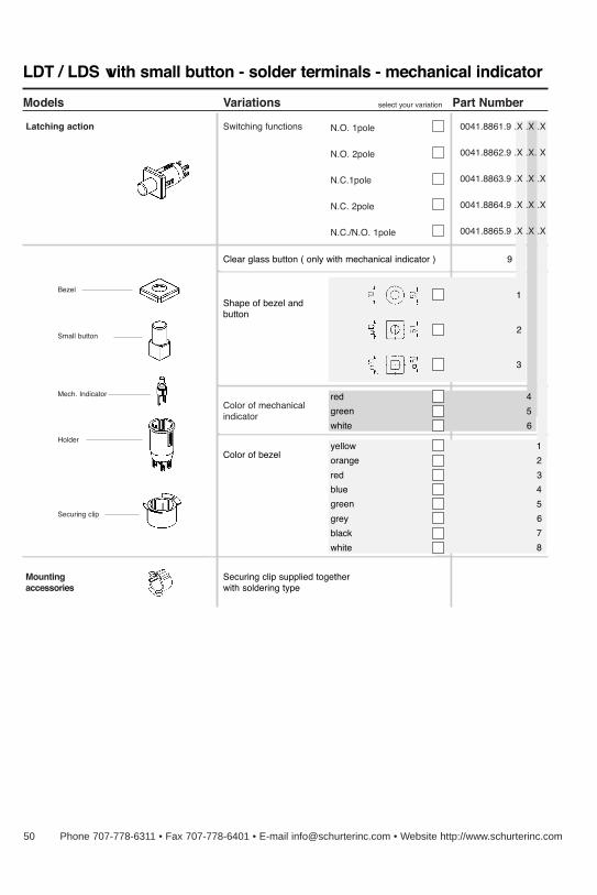
LDT / LDS with small button - solder terminals - mechanical indicator
Switching functions N.O. 1pole 0041.8861.9 .X .X .X
N.O. 2pole
N.C.1pole
N.C./N.O. 1pole
N.C. 2pole
Color of bezel
Latching action
0041.8862.9 .X .X. X
0041.8863.9 .X .X .X
0041.8864.9 .X .X .X
0041.8865.9 .X .X .X
Color of mechanicalindicator
red
green
white
4
5
6
blue
green
grey
black
white
yellow
orange
red
4
5
6
7
8
1
2
3
Securing clip supplied togetherwith soldering type
1
2
3
Shape of bezel andbutton
Clear glass button ( only with mechanical indicator ) 9
Mountingaccessories
Small button
Bezel
Holder
Securing clip
Mech. Indicator
Type Height and Type Face Index
MCS 1/2Ó, MTP 1/2", PMK Shape 1
single characters Univers 65
Legends with max. 6 characters in a line: Akzident-Groteskcondensed type
Color of insert plate or face foil anthracite RAL 7016
Color of legend light grey RAL 7035
A 4
RETURN 2
MTP 1/2", PMK Shape 2
single characters Helvetica normal DIN 1451-1E
Legends with 2-4 characters in a line: Helvetica normalDIN 1454-1E
Printing color white RAL 9016 for keycaps in red, green, greyand black
Printing color black RAL 9011 for keycap whiteLegends with 5-7 characters in a line: Helvetica condensed lightDIN 1454-3E
MTG 3/4", MCS 3/4", MTP 3/4" Shape 1
single characters Univers 65
Legends with max. 6 characters in a line: Univers 65
Iluminated version: Color of insert plate charcoal RAL 7016,legend s and symbols transparent
Non-illuminated version: Color of insert plate charcoal RAL7016, legends and symbols light grey RAL 7035
STOP 2,5
RETURN 2,38
MTP 3/4" Shape 2
A 6 single characters Helvetica normal DIN 1451-1E
Legends with 2-5 characters in a line: Helvetica normal DIN1454-1E
Printing colour white RAL 9016 for keycaps in red, green,grey and black
Printing colour black RAL 9011 for keycap whiteLegends with 6-7 characters in a line: Helvetica condensed lightDIN 1454-3E
MCS 3/4Ó and MMT 3/4" Shape 2
single characters Univers 65
Legends with max. 6 characters in a line: Univers 65
Color of insert plate or face foil charcoal RAL 7016
Color of legend light grey RAL 7035
LDT, LDS
single characters Univers 65
Legends with max. 6 characters in a line: Akzident-Groteskcondensed type
Color of insert plate or face foil charcoal RAL 7016
Color of legend light grey RAL 7035
Legend insert plate
hot stamped
Type height 4 mm 2 mm 1,5 mm
Illuminated version withlegend only possible forcustomer specific.
A 4
RETURN 2
A 5,03
RETURN 2,38
A 5,03
A 4
RETURN 2
RETURN 2,5
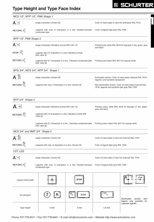
Phone 707-778-6311 ¥ Fax 707-778-6401 ¥ E-mail [email protected] ¥ Website http://www.schurterinc.com
Models Variations select your variation Part Number
LDT / LDS with small button - solder terminals - mechanical indicator
Switching functions N.O. 1pole 0041.8861.9 .X .X .X
N.O. 2pole
N.C.1pole
N.C./N.O. 1pole
N.C. 2pole
Color of bezel
Latching action
0041.8862.9 .X .X. X
0041.8863.9 .X .X .X
0041.8864.9 .X .X .X
0041.8865.9 .X .X .X
Color of mechanicalindicator
red
green
white
4
5
6
blue
green
grey
black
white
yellow
orange
red
4
5
6
7
8
1
2
3
Securing clip supplied togetherwith soldering type
1
2
3
Shape of bezel andbutton
Clear glass button ( only with mechanical indicator ) 9
Mountingaccessories
Small button
Bezel
Holder
Securing clip
Mech. Indicator
Type Height and Type Face Index
MCS 1/2Ó, MTP 1/2", PMK Shape 1
single characters Univers 65
Legends with max. 6 characters in a line: Akzident-Groteskcondensed type
Color of insert plate or face foil anthracite RAL 7016
Color of legend light grey RAL 7035
A 4
RETURN 2
MTP 1/2", PMK Shape 2
single characters Helvetica normal DIN 1451-1E
Legends with 2-4 characters in a line: Helvetica normalDIN 1454-1E
Printing color white RAL 9016 for keycaps in red, green, greyand black
Printing color black RAL 9011 for keycap whiteLegends with 5-7 characters in a line: Helvetica condensed lightDIN 1454-3E
MTG 3/4", MCS 3/4", MTP 3/4" Shape 1
single characters Univers 65
Legends with max. 6 characters in a line: Univers 65
Iluminated version: Color of insert plate charcoal RAL 7016,legend s and symbols transparent
Non-illuminated version: Color of insert plate charcoal RAL7016, legends and symbols light grey RAL 7035
STOP 2,5
RETURN 2,38
MTP 3/4" Shape 2
A 6 single characters Helvetica normal DIN 1451-1E
Legends with 2-5 characters in a line: Helvetica normal DIN1454-1E
Printing colour white RAL 9016 for keycaps in red, green,grey and black
Printing colour black RAL 9011 for keycap whiteLegends with 6-7 characters in a line: Helvetica condensed lightDIN 1454-3E
MCS 3/4Ó and MMT 3/4" Shape 2
single characters Univers 65
Legends with max. 6 characters in a line: Univers 65
Color of insert plate or face foil charcoal RAL 7016
Color of legend light grey RAL 7035
LDT, LDS
single characters Univers 65
Legends with max. 6 characters in a line: Akzident-Groteskcondensed type
Color of insert plate or face foil charcoal RAL 7016
Color of legend light grey RAL 7035
Legend insert plate
hot stamped
Type height 4 mm 2 mm 1,5 mm
Illuminated version withlegend only possible forcustomer specific.
A 4
RETURN 2
A 5,03
RETURN 2,38
A 5,03
A 4
RETURN 2
RETURN 2,5

52 Phone 707-778-6311 ¥ Fax 707-778-6401 ¥ E-mail [email protected] ¥ Website http://www.schurterinc.com
EMF / AF LIGHTED PUSHBUTTON SWITCHES, INDICATORS
General DescriptionEMF is a complete lighted pushbutton switches program for screw onpanel mount (mounting hole diameter 16mm). The forms of lenses areavailable in the dimensions rectangular 18 x 24 mm, square 18 x 18mm and round diameter 18mm. The pushbutton switches areequipped with a snap action element and 1-4 contact blocks. Eachcontact block can be used as N.C. or N.O. or change-over contact (forchange-over contact external. connection between terminals 2 and 4).Contacts in one section must be same polarity. EMF lightedpushbutton switches can be fitted with contactless elements byrequest.
Separation of the individual switching elements by contactless unitspermits high and low voltages to be applied to the same pushbuttonswitch. The 4 triplated terminals of each block are absolutely fluxproof. The lenses of EMF are available in 11 different colors and canbe lighted by Midget-Groove T1-3/4 incandescent lamps or LED. Theswitch positions of the alternate version of the pushbutton switches isalways indicated by the position of lens.
AF indicatorThe front dimensions and accessories such as lenses, legend plateinserts, incandescent lamps and LEDÕs for AF indicators are identicalto those for EMF lighted pushbutton switches.
EMF 18 x 24 EMF 18 x 18 EMF ¯ 18
1 pole
2 poles
3 poles
4 poles
AF
Technical data of illuminated pushbutton switches EMF (* for EMF and indicators AF)Switch system Each contact block has one double break, snap acting switching mechanism
Switch mode Momentary or alternate action, 1-4 poles
Contact material Silver for applications >15V and 20mA
Operating travel 3.2 mm
Actuating force > 1.5 N
Contact material Silver
Mechanical lifetime > 2 x 10⁶ Operations
* Storage temperature -40¡ C to + 85¡ C
* Vibration resistance IEC 68-2-6 Test Fc
* Insulation resistance > 104 M½ 500 V DC according to IEC 341-1
* Test voltage > 4000 V, 50 Hz, 1 min. between metal plate and terminals
* Climate category GVF with lamp, GPF without lamp according to DIN 40040
* Terminals Max. diameter of wire 2 x 0.8 mm; Max. diameter of stranded cable 0.75 mm2
* Solderability 350¡ C, 2 s, IEC 68-2-20, Test Ta, method 2
* Soldering heat resistance 350¡ C, 10 s, IEC 68-2-20, Test Tb, method 2
* Max. torque of nut max 1.2 Nm
* Approvals UL recognized at 5 A/250V (File #E 73407) SEMKO approved at 5 A/250 VCSA certified at 5 A/250V (File #LR 47016)
VDE approved at 5 A/250V (expert report) SEV approved at 5 A/250 Vwith factory surveillance), VDE #1827
* Materials Temperature resistant plastic; Current carrying parts Cu alloy;Contact housing molded in electrical high-grade thermosetting plastic
* Protection class Suitable for mounting in equipment with protection class II,in accordance to IEC 536
* Degree of protection IP 40, IEC 529 mounted from the front side (see page 101 for key to IP code)
* Operating temperature -40¡ C to + 55¡ C with incandescent lamp-40¡ C to + 85¡ C without incandescent lamp
Initial contact resistance (new) < 10 m½ Current 1 A AC, according to IEC 341-1, Test i, silver contactcontact bouncing time < 1ms
Electrical lifetime (at ohmic load)5 A/250 V AC > 50,000 Operations4 A/250 V AC > 60,000 Operations2 A/250 V AC > 200,000 Operations1 A/250 V AC > 400,000 Operations
Breaking capacity (at ohmic load) 250V/5A AC 250V/0.2 A DC

0041.2302
Phone 707-778-6311 ¥ Fax 707-778-6401 ¥ E-mail [email protected] ¥ Website http://www.schurterinc.com 53
EMF LIGHTED PUSHBUTTON SWITCHES
Models Dimensions
Ordering data for EMF body only (lenses, lamps, etc., accessories see pages 57-61)
Description TypeContact Diagram
(button not depressed)Length A
(mm)
35 0041.2301 0041.2311
0041.2303
0041.2304
0041.2351
0041.2352
0041.2353
0041.2354
0041.2312
0041.2313
0041.2314
0041.2361
0041.2362
0041.2363
0041.2364
0041.2321
0041.2322
0041.2323
0041.2324
0041.2371
0041.2372
0041.2373
0041.2374
43
51
59
43
51
59
35
Order No.Shape of pushbutton
lighted pushbutton, 1 pole,momentary action
SPSTfor SPDT use externalconnection between
terminal 2 and 4
DPSTfor DPDT use externalconnection between
terminal 2 and 4
3 PSTfor 3 PDT use external
connection betweenterminal 2 and 4
4 PSTfor 4 PDT use external
connection betweenterminal 2 and 4
SPSTfor SPDT use externalconnection between
terminal 2 and 4
DPSTfor DPDT use externalconnection between
terminal 2 and 4
3 PSTfor 3 PDT use external
connection betweenterminal 2 and 4
4 PSTfor 4 PDT use external
connection betweenterminal 2 and 4
lighted pushbutton, 2 poles,momentary action
lighted pushbutton, 3 poles,momentary action
lighted pushbutton, 4 poles,momentary action
lighted pushbutton, 1 pole,alternate action
lighted pushbutton, 2 poles,alternate action
lighted pushbutton, 3 poles,alternate action
lighted pushbutton, 4 poles,alternate action
Co
nta
cts
in o
ne
sect
ion
mu
st b
e sa
me
po
lari
ty
See pg. 52 for technical data
Panel cut-out
Panel cut-out
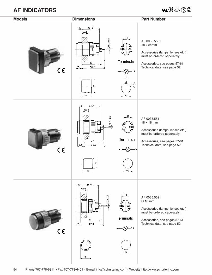
54 Phone 707-778-6311 ¥ Fax 707-778-6401 ¥ E-mail [email protected] ¥ Website http://www.schurterinc.com
AF INDICATORS
Models Dimensions Part Number
AF 0035.550118 x 24mm
Accessories (lamps, lenses etc.)must be ordered seperately.
Accessories, see pages 57-61Technical data, see page 52
AF 0035.551118 x 18 mm
Accessories (lamps, lenses etc.)must be ordered seperately.
Accessories, see pages 57-61Technical data, see page 52
AF 0035.5521 ¯ 18 mm
Accessories (lamps, lenses etc.)must be ordered seperately.
Accessories, see pages 57-61Technical data, see page 52
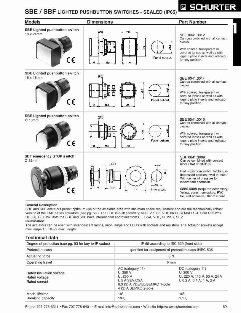
SBE / SBF LIGHTED PUSHBUTTON SWITCHES - SEALED (IP65)
Phone 707-778-6311 ¥ Fax 707-778-6401 ¥ E-mail [email protected] ¥ Website http://www.schurterinc.com 59
Models Dimensions Part Number
SBE 0041.3012Can be combined with all contactblocks.
With colored, transparent orcovered lenses as well as withlegend plate inserts and indicatorfor key position.
SBE Lighted pushbutton switch18 x 24mm
SBE 0041.3014Can be combined with all contactblocks.
With colored, transparent orcovered lenses as well as withlegend plate inserts and indicatorfor key position.
SBE 0041.3016Can be combined with all contactblocks.
With colored, transparent orcovered lenses as well as withlegend plate inserts and indicatorfor key position.
SBE Lighted pushbutton switch¯ 18mm
8 N
6 mm
AC (category 11) DC (category 11)Ui 250 V Ui 300 VUe 250 V Ue 220 V, 110 V, 60 V, 24 VIe 5 A SEV/CSA Ie 0.2 A, 0.4 A, 1 A, 2 A6.3 (3) A VDE/UL/SEMKO 1-pole4 (3) A SEMKO 2-pole
IP 65 according to IEC 529 (front side)
qualified for equipment of protection class II/IEC 536
Actuating force
Operating travel
Rated insulation voltageRated voltageRated current
Mech. lifetimeBreaking capacity
106 105
10¥Ie 1.1¥Ie
Protection class
Degree of protection (see pg. 93 for key to IP codes)
General DescriptionSBE and SBF actuators permit optimum use of the avialable area with minimum space requirement and are the mechanically robustversion of the EMF series actuators (see pg. 56 ). The SBE is built according to SEV 1005, VDE 0630, SEMKO 124, CSA C22.2/14,UL 508, CEE 24. Both the SBE and SBF have international approvals from UL, CSA, VDE, SEMKO, SEV. Illumination:The actuators can be used with incandescent lamps, neon lamps and LEDÕs with sockets and resistors. The actuator sockets acceptmini lamps T5, 5K-22 max. length.
SBE Lighted pushbutton switch18 x 18mm
SBF 0041.3009Can be combined with contactblock 0041.3101/3102
Red mushroom switch, latching indepressed position, twist to reset.With center of pressure forinadvertant operation.
0886.0008 (required accessory)Yellow, panel nameplate, PVCfoil, self adhesive, 16mm cutout
SBF emergency STOP switch¯ 32mm
Technical data
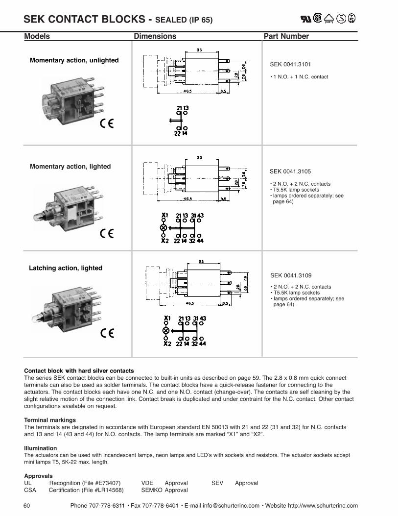
SEK CONTACT BLOCKS - SEALED (IP 65)
Models Dimensions Part Number
Contact block with hard silver contactsThe series SEK contact blocks can be connected to built-in units as described on page 59. The 2.8 x 0.8 mm quick connectterminals can also be used as solder terminals. The contact blocks have a quick-release fastener for connecting to theactuators. The contact blocks each have one N.C. and one N.O. contact (change-over). The contacts are self cleaning by theslight relative motion of the connection link. Contact break is duplicated and under contraint for the N.C. contact. Other contactconfigurations available on request.
Terminal markingsThe terminals are deignated in accordance with European standard EN 50013 with 21 and 22 (31 and 32) for N.C. contactsand 13 and 14 (43 and 44) for N.O. contacts. The lamp terminals are marked ÒX1Ó and ÒX2Ó.
IlluminationThe actuators can be used with incandescent lamps, neon lamps and LEDÕs with sockets and resistors. The actuator sockets acceptmini lamps T5, 5K-22 max. length.
ApprovalsUL Recognition (File #E73407) VDE Approval SEV ApprovalCSA Certification (File #LR14568) SEMKO Approval
60 Phone 707-778-6311 ¥ Fax 707-778-6401 ¥ E-mail [email protected] ¥ Website http://www.schurterinc.com
SEK 0041.3105
¥ 2 N.O. + 2 N.C. contacts¥ T5.5K lamp sockets ¥ lamps ordered separately; see
page 64)
SEK 0041.3109
¥ 2 N.O. + 2 N.C. contacts¥ T5.5K lamp sockets ¥ lamps ordered separately; see
page 64)
Momentary action, lighted
Latching action, lighted
Momentary action, unlightedSEK 0041.3101
¥ 1 N.O. + 1 N.C. contact
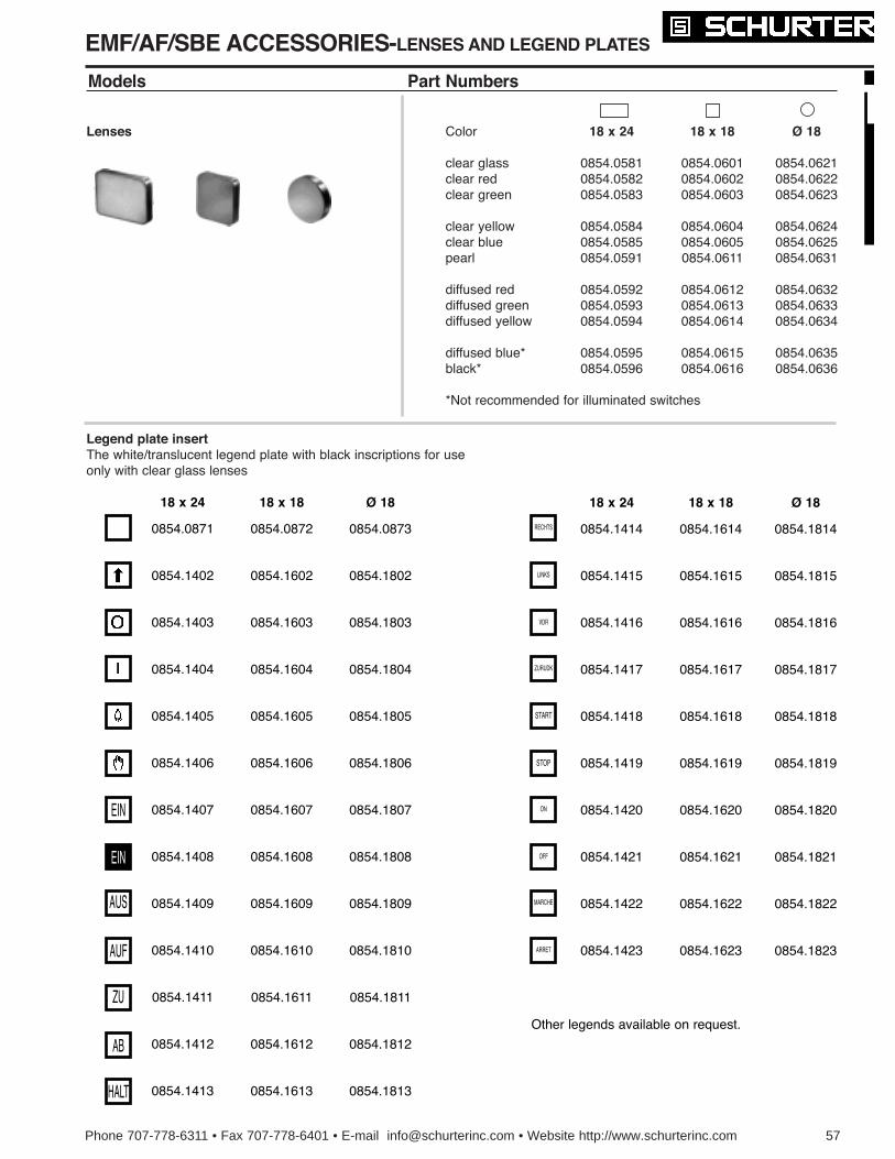
Phone 707-778-6311 • Fax 707-778-6401 • E-mail [email protected] • Website http://www.schurterinc.com 57
EMF/AF/SBE ACCESSORIES-LENSES AND LEGEND PLATES
Models Part Numbers
Lenses
Legend plate insertThe white/translucent legend plate with black inscriptions for useonly with clear glass lenses
Color
clear glassclear redclear green
clear yellowclear bluepearl
diffused reddiffused greendiffused yellow
diffused blue*black*
*Not recommended for illuminated switches
18 x 24
0854.05810854.05820854.0583
0854.05840854.05850854.0591
0854.05920854.05930854.0594
0854.05950854.0596
18 x 18
0854.06010854.06020854.0603
0854.06040854.06050854.0611
0854.06120854.06130854.0614
0854.06150854.0616
¯ 18
0854.06210854.06220854.0623
0854.06240854.06250854.0631
0854.06320854.06330854.0634
0854.06350854.0636
18 x 24
0854.0871
0854.1402
0854.1403
0854.1404
0854.1405
0854.1406
0854.1407
0854.1408
0854.1409
0854.1410
0854.1411
0854.1412
0854.1413
18 x 18
0854.0872
0854.1602
0854.1603
0854.1604
0854.1605
0854.1606
0854.1607
0854.1608
0854.1609
0854.1610
0854.1611
0854.1612
0854.1613
¯ 18
0854.0873
0854.1802
0854.1803
0854.1804
0854.1805
0854.1806
0854.1807
0854.1808
0854.1809
0854.1810
0854.1811
0854.1812
0854.1813
18 x 24
0854.1414
0854.1415
0854.1416
0854.1417
0854.1418
0854.1419
0854.1420
0854.1421
0854.1422
0854.1423
18 x 18
0854.1614
0854.1615
0854.1616
0854.1617
0854.1618
0854.1619
0854.1620
0854.1621
0854.1622
0854.1623
¯ 18
0854.1814
0854.1815
0854.1816
0854.1817
0854.1818
0854.1819
0854.1820
0854.1821
0854.1822
0854.1823
RECHTS
LINKS
VDR
ZURUDK
START
STOP
ON
OFF
MARCHE
ARRET
EIN
AUS
AUF
ZU
AB
HALT
EIN
Other legends available on request.
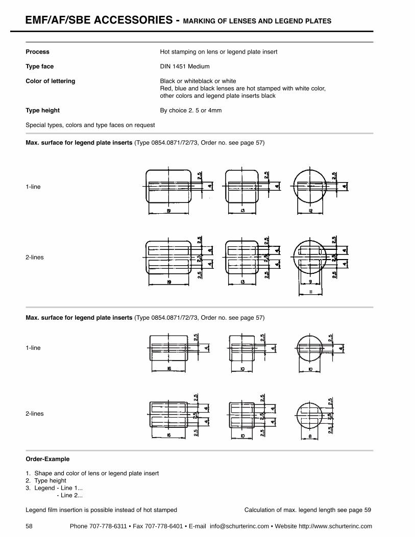
58 Phone 707-778-6311 • Fax 707-778-6401 • E-mail [email protected] • Website http://www.schurterinc.com
EMF/AF/SBE ACCESSORIES - MARKING OF LENSES AND LEGEND PLATES
Process Hot stamping on lens or legend plate insert
Type face DIN 1451 Medium
Color of lettering Black or whiteblack or whiteRed, blue and black lenses are hot stamped with white color,other colors and legend plate inserts black
Type height By choice 2. 5 or 4mm
Special types, colors and type faces on request
Max. surface for legend plate inserts (Type 0854.0871/72/73, Order no. see page 57)
1-line
2-lines
Max. surface for legend plate inserts (Type 0854.0871/72/73, Order no. see page 57)
1-line
2-lines
Order-Example
1. Shape and color of lens or legend plate insert2. Type height3. Legend - Line 1...
- Line 2...
Legend film insertion is possible instead of hot stamped Calculation of max. legend length see page 59
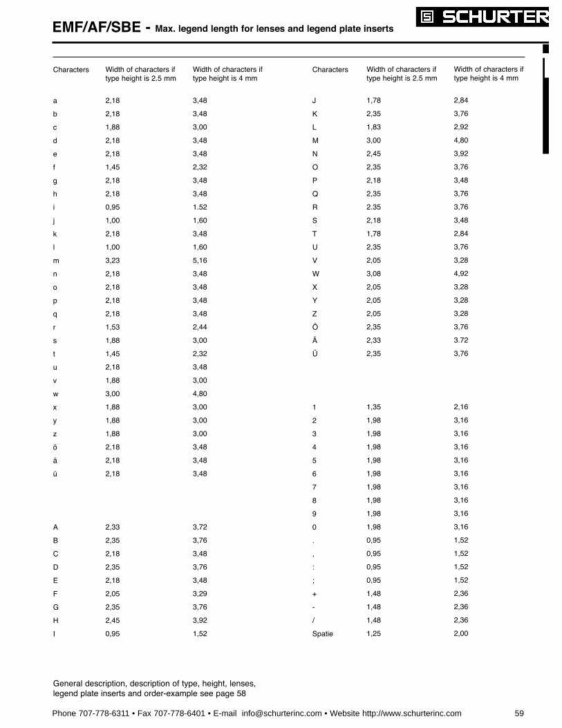
Phone 707-778-6311 • Fax 707-778-6401 • E-mail [email protected] • Website http://www.schurterinc.com 59
EMF/AF/SBE - Max. legend length for lenses and legend plate inserts
Characters
a
b
c
d
e
f
g
h
i
j
k
l
m
n
o
p
q
r
s
t
u
v
w
x
y
z
A
B
C
D
E
F
G
H
I
Characters
J
K
L
M
N
O
P
Q
R
S
T
U
V
W
X
Y
Z
1
2
3
4
5
6
7
8
9
0
.
,
:
;
+
-
/
Spatie
Width of characters iftype height is 2.5 mm
2,18
2,18
1,88
2,18
2,18
1,45
2,18
2,18
0,95
1,00
2,18
1,00
3,23
2,18
2,18
2,18
2,18
1,53
1,88
1,45
2,18
1,88
3,00
1,88
1,88
1,88
2,18
2,18
2,18
2,33
2,35
2,18
2,35
2,18
2,05
2,35
2,45
0,95
Width of characters iftype height is 4 mm
3,48
3,48
3,00
3,48
3,48
2,32
3,48
3,48
1.52
1,60
3,48
1,60
5,16
3,48
3,48
3,48
3,48
2,44
3,00
2,32
3,48
3,00
4,80
3,00
3,00
3,00
3,48
3,48
3,48
3,72
3,76
3,48
3,76
3,48
3,29
3,76
3,92
1,52
Width of characters iftype height is 2.5 mm
1,78
2,35
1,83
3,00
2,45
2,35
2,18
2,35
2.35
2,18
1,78
2,35
2,05
3,08
2,05
2,05
2,05
2,35
2,33
2,35
1,35
1,98
1,98
1,98
1,98
1,98
1,98
1,98
1,98
1,98
0,95
0,95
0,95
0,95
1,48
1,48
1,48
1,25
Width of characters iftype height is 4 mm
2,84
3,76
2,92
4,80
3,92
3,76
3,48
3,76
3,76
3,48
2,84
3,76
3,28
4,92
3,28
3,28
3,28
3,76
3.72
3,76
2,16
3,16
3,16
3,16
3,16
3,16
3,16
3,16
3,16
3,16
1,52
1,52
1,52
1,52
2,36
2,36
2,36
2,00
General description, description of type, height, lenses,legend plate inserts and order-example see page 58

EMF/AF ACCESSORIES - Incandescent and neon lamps, LEDÕs and mounting tools
SBE ACCESSORIES
Incandescent lamp T 13ÚÚ4 midget groove Voltage
6.3 V14 V28 V
48 V60 V24 V
Consumption
200 mA80 mA40 mA
25 mA20 mA50 mA
Brightness
.40 MSCP
.20 MSCP
.20 MSCP
.20 MSCP
.30 MSCP
.18 MSCP
Lifetime
AC50,000 h15,000 h10,000 h
5,000 h1,000 h
10,000 h
DC25,000 h
7,000 h5,000 h
2,000 h1,000 h5,000 h
Order no.0913.40010913.40020913.4003
0913.40040913.40050913.4006
Operatingvoltage
Order no.0925.0104 red0925.0105 green0925.0106 yellow
0925.0107 red0925.0108 green0925.0109 yellow
0925.0110 red0925.0111 green0925.0112 yellow
Incandescent lamps with lower power consumption on request.
The use of incandescent lamps >60V is limited by different standards. Check with testing agency.Series resistors for incandescent lamps and capacitors for the reduction of lamp voltage available on request.
Neon lamp T 13ÚÚ4 Midget Groove (requires external resistor)
LED T 13ÚÚ4 Midget Groove
Lamp extractor Mounting Key
Order no. Order no.0853.0621 0853.0622
Incandescent lamps with socket T5,5K 0913.1106 6 Volt/1,2 W0913.1112 12 Volt/1,2 W0913.1124 24 Volt/1,2 W0913.1136 36 Volt/1,2 W (35 mA)0913.1148 48 Volt/1,2 W (25 mA)0913.1160 60 Volt/1,2 W (20 mA)
Neon lamps with socket T5,5K 0923.1016 110 Volt0923.1017 220 Volt
LEDÕs with 4 system LEDsocket T5,5Kand built-in resistor for 24 V, 18 mA
for 115 Vac, add 33K½/³ 1Ú4 Wattfor 220 Vac, add 100K½/³ 1Ú4 Watt
Order no.0923.3001
Base contact Note: certain safety agency limitations may apply.
Base contact= + polarity
UB
[V]
666
121212
282828
Reversevoltage
UR
[V]
888
161616
161616
Operatingcurrent
IF
[mA]
303030
151515
101010
Powerdissipation
PTOT
[mW]
250250250
250250250
300300300
Peakwave
peak[nm]
700555570
700555570
700555570
Reversecurrent
IR
[ µA]
100100100
100100100
100100100
Luminousintensit
IV
[mcd]
73022
73022
73022
Operatingtemperature
¡C
-25¡Cto
+70¡ C
Storagetemperature
¡C
-25¡Cto
+85¡ C
60 Phone 707-778-6311 • Fax 707-778-6401 • E-mail [email protected] • Website http://www.schurterinc.com
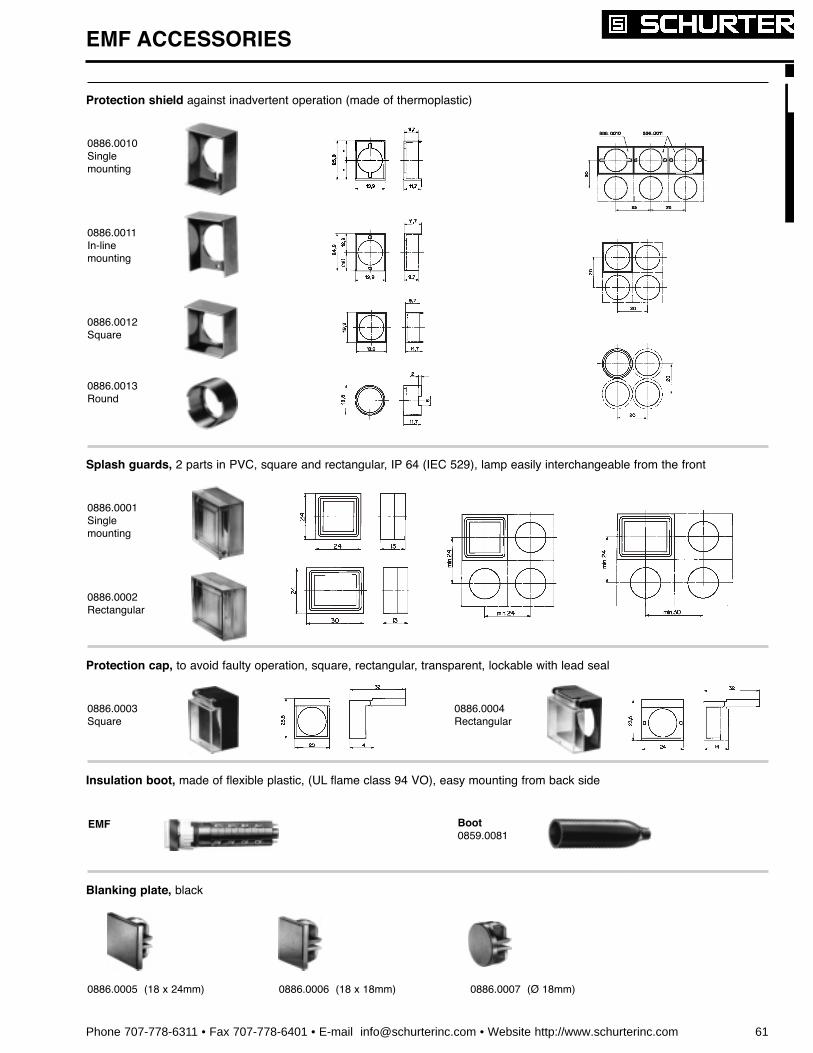
Phone 707-778-6311 • Fax 707-778-6401 • E-mail [email protected] • Website http://www.schurterinc.com 61
EMF ACCESSORIES
Protection shield against inadvertent operation (made of thermoplastic)
Splash guards, 2 parts in PVC, square and rectangular, IP 64 (IEC 529), lamp easily interchangeable from the front
0886.0010Singlemounting
0886.0011In-linemounting
0886.0012Square
0886.0013Round
0886.0001Singlemounting
0886.0002Rectangular
Protection cap, to avoid faulty operation, square, rectangular, transparent, lockable with lead seal
0886.0003Square
Blanking plate, black
0886.0005 (18 x 24mm) 0886.0006 (18 x 18mm) 0886.0007 (¯ 18mm)
Insulation boot, made of flexible plastic, (UL flame class 94 VO), easy mounting from back side
EMF Boot0859.0081
0886.0004Rectangular

Part No. Ligh color Form
IF max.[mA]
ForwardDC currentflow
Powerdissipation
Deration Forwardvoltage
Luminousintensity
Viewingangle
Peak wavelength
Reversevoltage
Limit value Value at Tu = 25 ¡C
0925.0030
0925.0067
0925.0029
Tu=25¡CPtot[mW]
Tu>25¡CPD[mW/¡C]
IF=10 mAUF[V] UR[V]
IF=10 mAIv[mcd]
peak [nm]
±[degree]
green
yellow
red
green
yellow
red
green
yellow
red
green
yellow
red
yellow
green
red
green
yellow
red
green
yellow
red
3mm T1 45 150 1,9 2,0 (<2,6)
2,0 (<2,6)
1,6 (<2,0)
4,0 - 12,5
6,3 - 20
1,0 - 3,2
70 565
585
660
5
0925.0060
0925.0061
0925.0059
5mm T1-3/4 45 150 1,9 2,0 (<2,6) 2,5 - 8,0
2,5 - 5,0
2,5 - 8,0
140 565
586
635
5
0925.9202
0925.9203
0925.9201
5mm T1-3/4 45 150 1,9 4,0 - 12,5
4,0 - 8,0
1,0 - 2,0
50 565
586
660
52,0 (<2,6)
2,0 (<2,6)
1,6 (<2,0)
0925.9205
0925.9206
0925.92045 x 2.5mm
T1-3/445 150 1,9 2,0 (<2,6) 2,5 - 5,0 100 560
590
635
5
0925.9300
0925.9301
0925.9299
90 135 1,5 (<3,0) 1,0 - 3,0 90 583
565
635
60
90
85
135
5
0925.9725
0925.9726
0925.9724
3mm T1 7,5 20 1,9 (<2,6) 1 - 5**
1 - 5**
0,63 - 5**
2,0 (<2,7)
1,8 (<2,6)
60 565
586
635
5
0925.9731
0925.9732
0925.9730
3mm T1 45 150 2,0 (<2,6) 16 - 50
10 - 32
10 - 32
2,0 (<2,6)
1,6 (<2,0)
50 565
586
660
5
LED Technical Data
Calculation of necessary external current limiting resistorand max. permissible dissipation at increased ambienttemperature
For Tamb < 25¡C
RS = Series-resistor in k½
UB = Connection voltage in V
UF = Forward voltage in V
IF = DC current flow in mA
RS = UB - UF / IF
** Luminous intensity at IF = 2 mA
Dimensions
(set min. or typical value)
(max. value see limit value)
For Tamb < 25¡C first calculate IF max.
Ptot = max. permissible power dissipation in mW
ÆP = (Tamb > 25¡C ) PD in mW
UF max. = Forward voltage in V
IF max. = max. permissible DC current flowfor appropriate Tamb in mA
IF max. = Ptot - ÆP / UF max.
(set max. value)
Phone 707-778-6311 ¥ Fax 707-778-6401 ¥ E-mail [email protected] • Website http://www.schurterinc.com 87

Schurter, Inc. • Phone 707-778-6311 • Fax 707-778-6401 • E-mail [email protected] • Website http://www.schurterinc.com 95
(VDE)Selector Chart For Voltage Selector Switches
Series / page number SWA / 98 SWA / 98 SWM / 98 SWM / 98
Panel mounting • •
Pcb mounting • •
Solder/quick-connect terminals
Solder terminals • •
Series / page number SWS / 99, SWK / 100 SWG / 100
Panel mounting • •
Pcb mounting
Solder/quick-connect terminals •
Solder terminals • •
6 Switch Positionswith fuseholder for 5 x 20mm fuses
6 Switch Positionswith fuseholder for 5 x 20mm or 1/4 x 11/4" fuses
Series / page number SWZ / 99 SWZ / 99 SWP / 100
Panel mounting • •
Pcb mounting •
Solder/quick-connect terminals •
Solder terminals •
6 Switch Positionswith short circuit pin6 Switch Positions
2 Switch Positions 3 Switch Positions
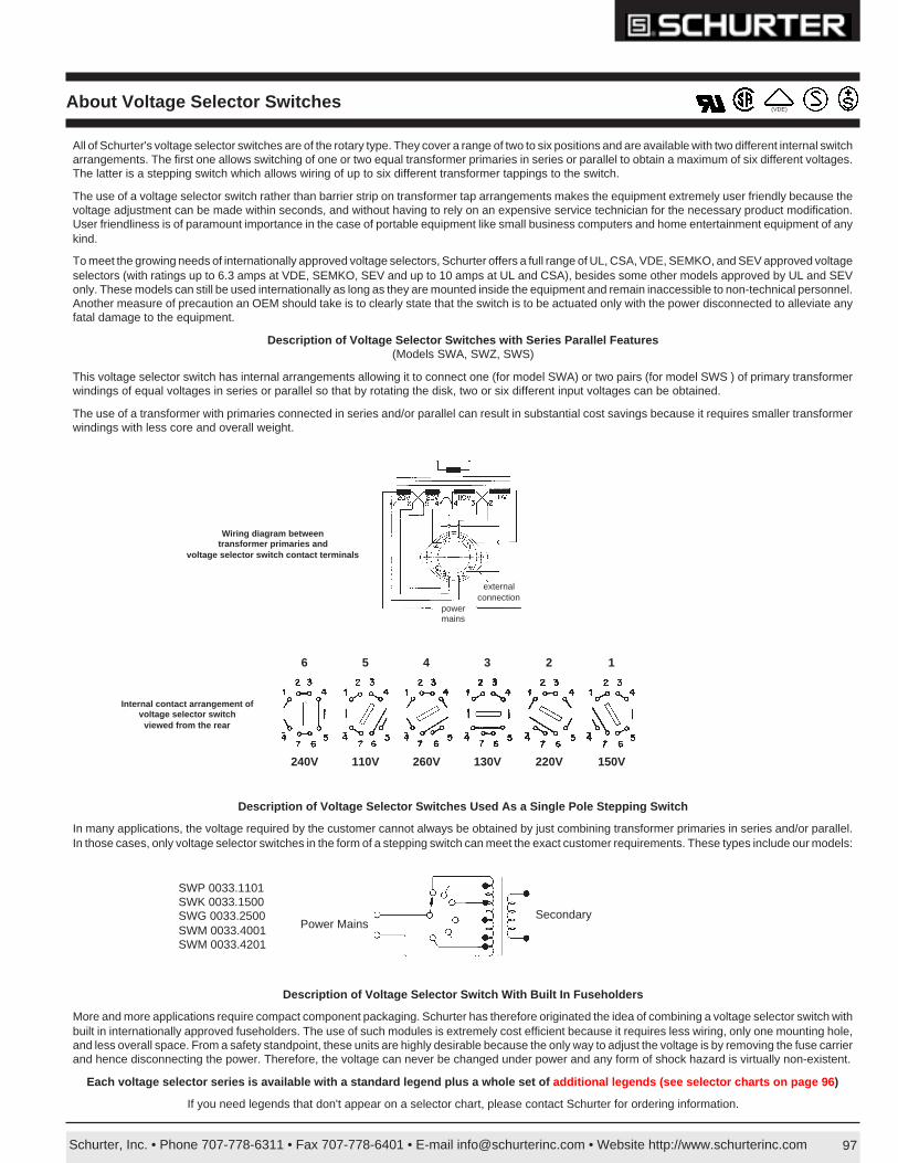
Schurter, Inc. • Phone 707-778-6311 • Fax 707-778-6401 • E-mail [email protected] • Website http://www.schurterinc.com 97
(VDE)About Voltage Selector Switches
All of Schurter's voltage selector switches are of the rotary type. They cover a range of two to six positions and are available with two different internal switcharrangements. The first one allows switching of one or two equal transformer primaries in series or parallel to obtain a maximum of six different voltages.The latter is a stepping switch which allows wiring of up to six different transformer tappings to the switch.
The use of a voltage selector switch rather than barrier strip on transformer tap arrangements makes the equipment extremely user friendly because thevoltage adjustment can be made within seconds, and without having to rely on an expensive service technician for the necessary product modification.User friendliness is of paramount importance in the case of portable equipment like small business computers and home entertainment equipment of anykind.
To meet the growing needs of internationally approved voltage selectors, Schurter offers a full range of UL, CSA, VDE, SEMKO, and SEV approved voltageselectors (with ratings up to 6.3 amps at VDE, SEMKO, SEV and up to 10 amps at UL and CSA), besides some other models approved by UL and SEVonly. These models can still be used internationally as long as they are mounted inside the equipment and remain inaccessible to non-technical personnel.Another measure of precaution an OEM should take is to clearly state that the switch is to be actuated only with the power disconnected to alleviate anyfatal damage to the equipment.
Description of Voltage Selector Switches with Series Parallel Features(Models SWA, SWZ, SWS)
This voltage selector switch has internal arrangements allowing it to connect one (for model SWA) or two pairs (for model SWS ) of primary transformerwindings of equal voltages in series or parallel so that by rotating the disk, two or six different input voltages can be obtained.
The use of a transformer with primaries connected in series and/or parallel can result in substantial cost savings because it requires smaller transformerwindings with less core and overall weight.
Description of Voltage Selector Switch With Built In Fuseholders
More and more applications require compact component packaging. Schurter has therefore originated the idea of combining a voltage selector switch withbuilt in internationally approved fuseholders. The use of such modules is extremely cost efficient because it requires less wiring, only one mounting hole,and less overall space. From a safety standpoint, these units are highly desirable because the only way to adjust the voltage is by removing the fuse carrierand hence disconnecting the power. Therefore, the voltage can never be changed under power and any form of shock hazard is virtually non-existent.
Each voltage selector series is available with a standard legend plus a whole set of additional legends (see selector charts on page 96 )
If you need legends that don't appear on a selector chart, please contact Schurter for ordering information.
Description of Voltage Selector Switches Used As a Single Pole Stepping Switch
In many applications, the voltage required by the customer cannot always be obtained by just combining transformer primaries in series and/or parallel.In those cases, only voltage selector switches in the form of a stepping switch can meet the exact customer requirements. These types include our models:
SWP 0033.1101SWK 0033.1500SWG 0033.2500SWM 0033.4001SWM 0033.4201
Power MainsSecondary
powermains
externalconnection
Wiring diagram betweentransformer primaries and
voltage selector switch contact terminals
6
240V
5
110V
4
260V
3
130V
2
220V
1
150V
Internal contact arrangement ofvoltage selector switch
viewed from the rear
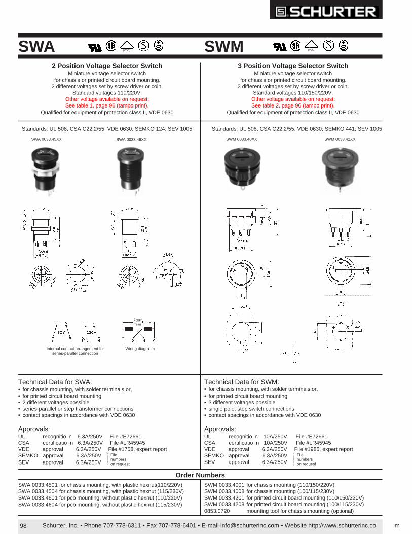
Schurter, Inc. • Phone 707-778-6311 • Fax 707-778-6401 • E-mail [email protected] • Website http://www.schurterinc.co m98
SWA SWM2 Position Voltage Selector Switch
Miniature voltage selector switchfor chassis or printed circuit board mounting.
2 different voltages set by screw driver or coin.Standard voltages 110/220V.
Other voltage available on request:See table 1, page 96 (tampo print).
Qualified for equipment of protection class II, VDE 0630
3 Position Voltage Selector SwitchMiniature voltage selector switch
for chassis or printed circuit board mounting.3 different voltages set by screw driver or coin.
Standard voltages 110/150/220V.Other voltage available on request:See table 2, page 96 (tampo print).
Qualified for equipment of protection class II, VDE 0630
(VDE) (VDE)
SWA 0033.4501 for chassis mounting, with plastic hexnut(110/220V)SWA 0033.4504 for chassis mounting, with plastic hexnut (115/230V)SWA 0033.4601 for pcb mounting, without plastic hexnut (110/220V)SWA 0033.4604 for pcb mounting, without plastic hexnut (115/230V)
SWM 0033.4001 for chassis mounting (110/150/220V)SWM 0033.4008 for chassis mounting (100/115/230V)SWM 0033.4201 for printed circuit board mounting (110/150/220V)SWM 0033.4208 for printed circuit board mounting (100/115/230V)0853.0720 mounting tool for chassis mounting (optional)
Order Numbers
Technical Data for SWA:• for chassis mounting, with solder terminals or,• for printed circuit board mounting• 2 different voltages possible• series-parallel or step transformer connections• contact spacings in accordance with VDE 0630
Approvals:UL recognitio n 6.3A/250V File #E72661CSA certificatio n 6.3A/250V File #LR45945VDE approval 6.3A/250V File #1758, expert reportSEMKO approval 6.3A/250VSEV approval 6.3A/250V
Technical Data for SWM:• for chassis mounting, with solder terminals or,• for printed circuit board mounting• 3 different voltages possible• single pole, step switch connections• contact spacings in accordance with VDE 0630
Approvals:UL recognitio n 10A/250V File #E72661CSA certificatio n 10A/250V File #LR45945VDE approval 6.3A/250V File #1985, expert reportSEMKO approval 6.3A/250VSEV approval 6.3A/250V
Filenumberson request
Filenumberson request
Standards: UL 508, CSA C22.2/55; VDE 0630; SEMKO 124; SEV 1005 Standards: UL 508, CSA C22.2/55; VDE 0630; SEMKO 441; SEV 1005
Wiring diagra mInternal contact arrangement forseries-parallel connection
Powermains
SWM 0033.40XXSWA 0033.45XX SWA 0033.46XX SWM 0033.42XX
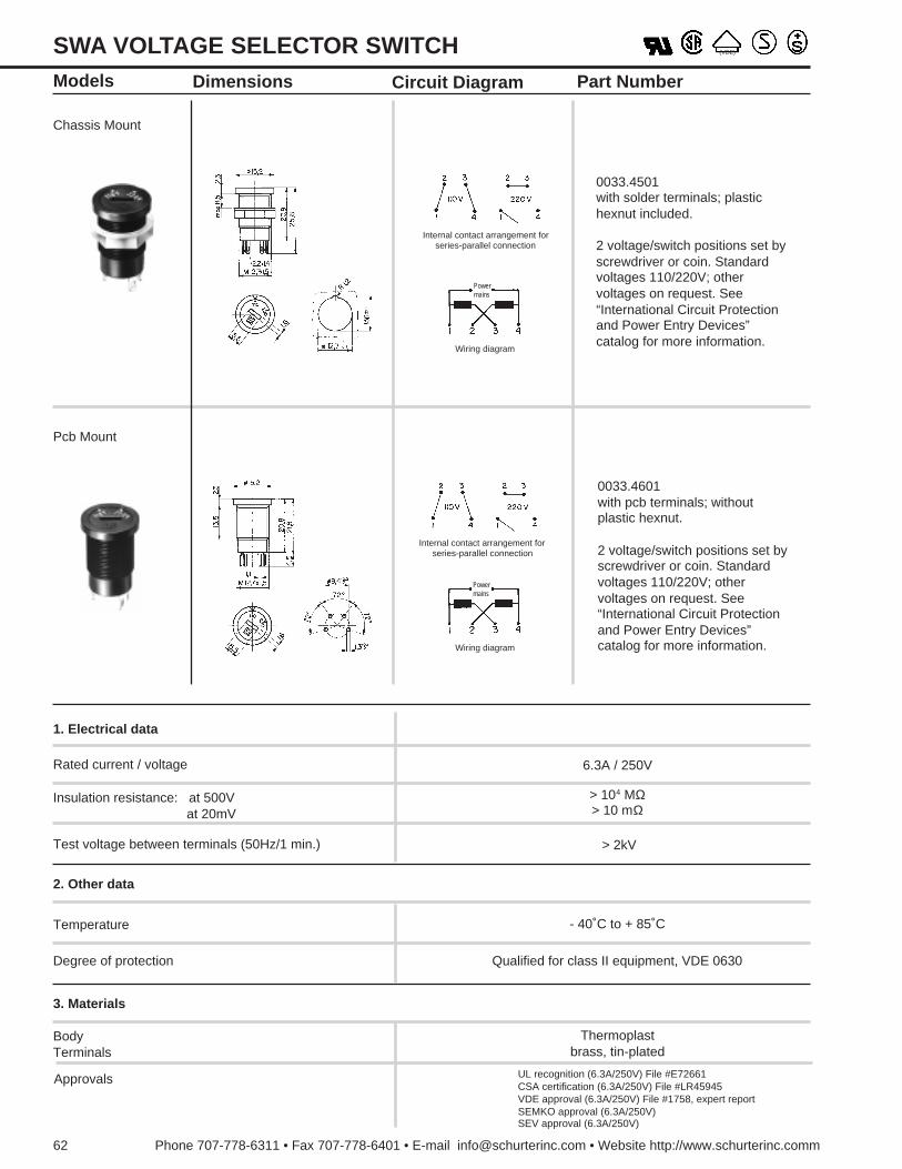
Phone 707-778-6311 • Fax 707-778-6401 • E-mail [email protected] • Website http://www.schurterinc.comm62
SWA VOLTAGE SELECTOR SWITCHModels
Pcb Mount
Internal contact arrangement forseries-parallel connection
Wiring diagram
Powermains
Internal contact arrangement forseries-parallel connection
Chassis Mount
Wiring diagram
Powermains
(VDE)
0033.4501with solder terminals; plastichexnut included.
2 voltage/switch positions set byscrewdriver or coin. Standardvoltages 110/220V; othervoltages on request. See“International Circuit Protectionand Power Entry Devices”catalog for more information.
0033.4601with pcb terminals; withoutplastic hexnut.
2 voltage/switch positions set byscrewdriver or coin. Standardvoltages 110/220V; othervoltages on request. See“International Circuit Protectionand Power Entry Devices”catalog for more information.
Dimensions Circuit Diagram Part Number
1. Electrical data
3. Materials
Degree of protection Qualified for class II equipment, VDE 0630
- 40˚C to + 85˚CTemperature
2. Other data
Test voltage between terminals (50Hz/1 min.) > 2kV
> 104 MΩ> 10 mΩ
Insulation resistance: at 500V at 20mV
Rated current / voltage 6.3A / 250V
BodyTerminals
Thermoplastbrass, tin-plated
Approvals UL recognition (6.3A/250V) File #E72661CSA certification (6.3A/250V) File #LR45945VDE approval (6.3A/250V) File #1758, expert reportSEMKO approval (6.3A/250V)SEV approval (6.3A/250V)
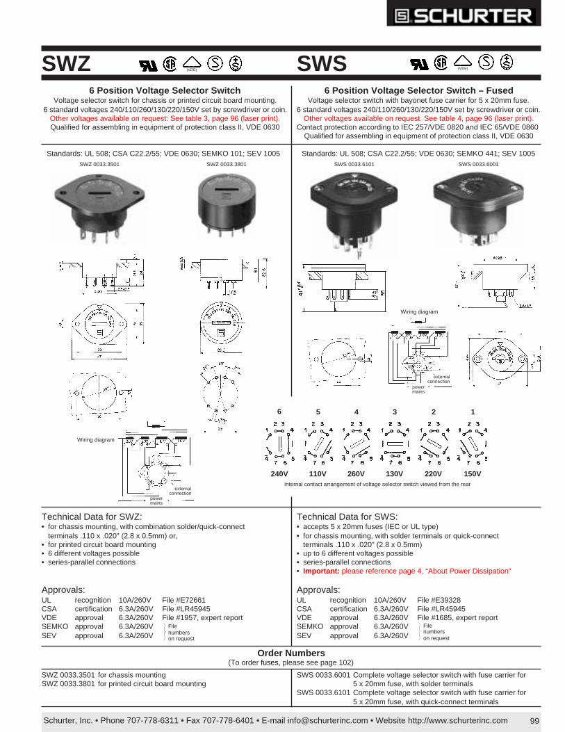
Schurter, Inc. • Phone 707-778-6311 • Fax 707-778-6401 • E-mail [email protected] • Website http://www.schurterinc.com 99
SWS 0033.6001 Complete voltage selector switch with fuse carrier for5 x 20mm fuse, with solder terminals
SWS 0033.6101 Complete voltage selector switch with fuse carrier for5 x 20mm fuse, with quick-connect terminals
SWZ6 Position Voltage Selector Switch
Voltage selector switch for chassis or printed circuit board mounting.6 standard voltages 240/110/260/130/220/150V set by screwdriver or coin.
Other voltages available on request: See table 3, page 96 (laser print).Qualified for assembling in equipment of protection class II, VDE 0630
SWS(VDE)
6 Position Voltage Selector Switch – FusedVoltage selector switch with bayonet fuse carrier for 5 x 20mm fuse.
6 standard voltages 240/110/260/130/220/150V set by screwdriver or coin.Other voltages available on request. See table 4, page 96 (laser print).
Contact protection according to IEC 257/VDE 0820 and IEC 65/VDE 0860Qualified for assembling in equipment of protection class II, VDE 0630
Order Numbers(To order fuses, please see page 102)
SWZ 0033.3501 for chassis mountingSWZ 0033.3801 for printed circuit board mounting
(VDE)
6
240V
5
110V
4
260V
3
130V
2
220V
1
150VInternal contact arrangement of voltage selector switch viewed from the rear
Technical Data for SWZ:• for chassis mounting, with combination solder/quick-connect
terminals .110 x .020" (2.8 x 0.5mm) or,• for printed circuit board mounting• 6 different voltages possible• series-parallel connections
Approvals:UL recognition 10A/260V File #E72661CSA certification 6.3A/260V File #LR45945VDE approval 6.3A/260V File #1957, expert reportSEMKO approval 6.3A/260VSEV approval 6.3A/260V
Technical Data for SWS:• accepts 5 x 20mm fuses (IEC or UL type)• for chassis mounting, with solder terminals or quick-connect
terminals .110 x .020" (2.8 x 0.5mm)• up to 6 different voltages possible• series-parallel connections• Important: please reference page 4, “About Power Dissipation”
Approvals:UL recognition 10A/260V File #E39328CSA certification 6.3A/260V File #LR45945VDE approval 6.3A/260V File #1685, expert reportSEMKO approval 6.3A/260VSEV approval 6.3A/260V
Filenumberson request
Filenumberson request
Wiring diagram
externalconnection
powermains
Wiring diagram
externalconnection
powermains
Standards: UL 508; CSA C22.2/55; VDE 0630; SEMKO 101; SEV 1005 Standards: UL 508; CSA C22.2/55; VDE 0630; SEMKO 441; SEV 1005SWZ 0033.3801 SWS 0033.6101 SWS 0033.6001SWZ 0033.3501
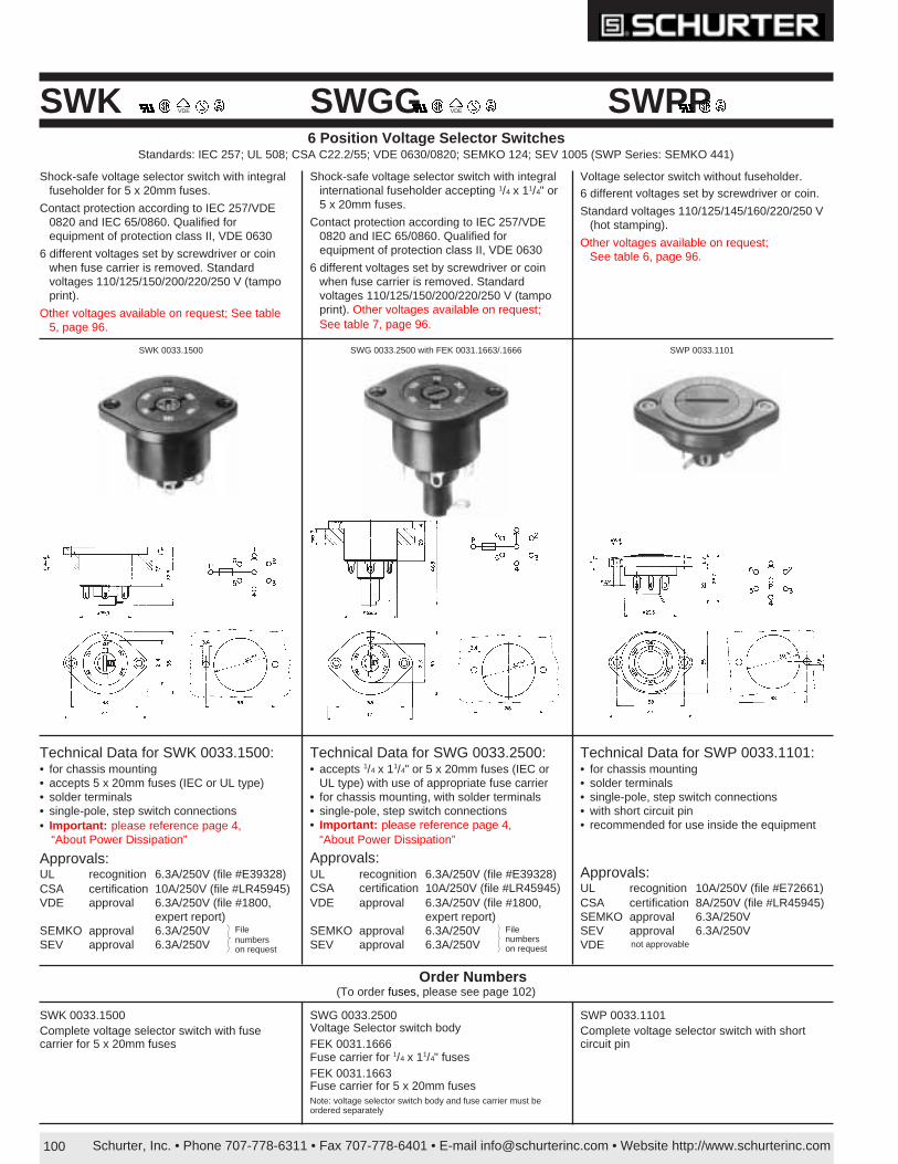
Schurter, Inc. • Phone 707-778-6311 • Fax 707-778-6401 • E-mail [email protected] • Website http://www.schurterinc.com100
SWPPSWGGSWK6 Position Voltage Selector Switches
Standards: IEC 257; UL 508; CSA C22.2/55; VDE 0630/0820; SEMKO 124; SEV 1005 (SWP Series: SEMKO 441)
Technical Data for SWK 0033.1500:• for chassis mounting• accepts 5 x 20mm fuses (IEC or UL type)• solder terminals• single-pole, step switch connections• Important: please reference page 4,
“About Power Dissipation”
Approvals:UL recognition 6.3A/250V (file #E39328)CSA certification 10A/250V (file #LR45945)VDE approval 6.3A/250V (file #1800,
expert report)SEMKO approval 6.3A/250VSEV approval 6.3A/250V
Technical Data for SWP 0033.1101:• for chassis mounting• solder terminals• single-pole, step switch connections• with short circuit pin• recommended for use inside the equipment
Approvals:UL recognition 10A/250V (file #E72661)CSA certification 8A/250V (file #LR45945)SEMKO approval 6.3A/250VSEV approval 6.3A/250VVDE
Technical Data for SWG 0033.2500:• accepts 1/4 x 11/4" or 5 x 20mm fuses (IEC or
UL type) with use of appropriate fuse carrier• for chassis mounting, with solder terminals• single-pole, step switch connections• Important: please reference page 4,
“About Power Dissipation”
Approvals:UL recognition 6.3A/250V (file #E39328)CSA certification 10A/250V (file #LR45945)VDE approval 6.3A/250V (file #1800,
expert report)SEMKO approval 6.3A/250VSEV approval 6.3A/250V
VDE VDE
SWP 0033.1101SWG 0033.2500 with FEK 0031.1663/.1666SWK 0033.1500
Shock-safe voltage selector switch with integralfuseholder for 5 x 20mm fuses.
Contact protection according to IEC 257/VDE0820 and IEC 65/0860. Qualified forequipment of protection class II, VDE 0630
6 different voltages set by screwdriver or coinwhen fuse carrier is removed. Standardvoltages 110/125/150/200/220/250 V (tampoprint).
Other voltages available on request; See table5, page 96.
Shock-safe voltage selector switch with integralinternational fuseholder accepting 1/4 x 11/4" or5 x 20mm fuses.
Contact protection according to IEC 257/VDE0820 and IEC 65/0860. Qualified forequipment of protection class II, VDE 0630
6 different voltages set by screwdriver or coinwhen fuse carrier is removed. Standardvoltages 110/125/150/200/220/250 V (tampoprint). Other voltages available on request;See table 7, page 96.
Voltage selector switch without fuseholder.6 different voltages set by screwdriver or coin.
Standard voltages 110/125/145/160/220/250 V(hot stamping).
Other voltages available on request;See table 6, page 96.
Filenumberson request
Filenumberson request
Order Numbers(To order fuses, please see page 102)
SWK 0033.1500Complete voltage selector switch with fusecarrier for 5 x 20mm fuses
SWG 0033.2500Voltage Selector switch bodyFEK 0031.1666Fuse carrier for 1/4 x 11/4" fusesFEK 0031.1663Fuse carrier for 5 x 20mm fusesNote: voltage selector switch body and fuse carrier must beordered separately
SWP 0033.1101Complete voltage selector switch with shortcircuit pin
not approvable

Schurter, Inc. • Phone 707-778-6311 • Fax 707-778-6401 • E-mail [email protected] • Website http://www.schurterinc.com96
* Indicates standard model (schematics shown on page 97).All other models are special order (schematics may differ from that of the standard models. Drawings for special models are available on request).
SWGOrder No.
Legends (positions 1-6)
1 2 3 4 5 6*033.2500 110 125 150 200 220 250033.2501 100V 110V 118V 220V 240V033.2502 100 240 220 120 110033.2503 100V 110V 120V 210V 220V 240V033.2504 110V 120V 130V 220V 230V 240V033.2505 220 120 240 110033.2506 208 220 240033.2507 100 110 120 200 220 240033.2508 125 120 115 110 100033.2509 +9% +4% 0% -4% -13%033.2510 100 115 220 230 240033.2511 200V 208V 220V 230V 240V NC033.2512 100V 120V 200V 220V 240V033.2513 120V 200V 220V 240V033.2514 blank blank blank blank blank blank033.2517 240V 230V 220V 208V 115V 100V033.2520 100 115 220 240
Order No. SWS with
Solder Terminals
Order No. SWS with Quick-con. Terminals
Legends (positions 1-6)
1 2 3 4 5 6*033.6001 *033.6101 150 220 130 260 110 240033.6002 127 200 115 240 100 220033.6003 033.6103 110 220033.6004 033.6104 140 200 120 240 100 220033.6006 130 220 120 240 110 230033.6007 033.6107 110 220033.6008 240 110 220033.6009 127 200 115 240 100 220033.6010 110 127 220 240033.6011 220 130 110 240033.6012 110 127 220 240033.6013 033.6113 100 115 220 240
033.6014 033.6114 blank blank blank blank blank blank
033.6015 120 240 100 220033.6016 220 120 240033.6017 220 127 240 110033.6019 033.6119 200 120 240 100 220033.6021 220 120 240 110033.6022 033.6122 220 120 100 240033.6023 220 127 110 240033.6024 130 200 115 230 100 220033.6025 110 127 220033.6026 120 220 100 240
033.6127 240 100 120 220033.6028 127 200 115 230 100033.6029 100 120 140 200 220 240033.6030 200 115 230 100 215033.6031 220 110 240
Order No. Panel Mount SWM
Order No. Printed Circuit
Mnt. SWM
Legends (positions 1-3)
1 2 3*033.4001 *033.4201 110 150 220033.4002 110 220 240033.4003 220 240033.4004 200 220 240033.4005 100 110 115033.4006 220 240 250033.4007 120 220 240033.4008 100 115 230033.4009 100 115 130033.4010 110 220033.4011 220 230 240033.4012 110 120 127033.4013 120 240033.4014 *033.4214 blank blank blank033.4015 100 110 220033.4016 1/8 1/8 1/8033.4017 50 Hz OFF 60 Hz033.4018 110 240 220033.4019 115 220 240033.4020 0 1 0033.4021 100 120033.4022 200 210 220033.4023 115 230 250033.4024 110 115 120033.4026 100 120 240033.4029 LO MED HI033.4032 4 8 16033.4038 110 220033.4039 110 127 230033.4040 100 110 230
033.4241 100V 120V 220V033.4044 115 0 230033.4045 208 220 240033.4046 100 110 120033.4047 110 230 240033.4048 42V 110V 220V033.4049 230 240 250033.4050 210 220 230033.4051 50 Hz 60 Hz033.4055 115V 230V 240V033.4056 1 2 3033.4061 230 115 0
Order No. Panel Mount
SWA
Order No. Printed Circuit
Mnt. SWA
Legends (positions 1 and 2)
1 2*033.4501 *033.4601 110 220033.4502 *033.4602 115 220033.4503 *033.4603 120 240033.4504 *033.4604 115 230033.4505 *033.4605 220 240033.4506 *033.4606 120 220033.4508 033.4608 50 Hz 60 Hz033.4509 033.4609 110 240033.4510 033.4610 230 240033.4513 033.4613 LO HI033.4514 *033.4614 blank blank033.4515 033.4615 120 230033.4516 033.4616 240 250033.4517 033.4617 100 120033.4518 033.4618 0 I033.4519 033.4619 100 230
Table 3Series SWZ(see page 99for technical data)
Table 2Series SWM(see page 98for technical data)
Table 4Series SWS(see page 99for technical data)
Table 1Series SWA(see page 98for technical data)
Table 7Series SWG(see page 100for technical data)
Table 6Series SWP(see page 100for technical data)
Selector Charts For Voltage Selector Legends
SWKOrder No.
Legends (positions 1-6)
1 2 3 4 5 6*033.1500 110 125 150 200 220 250033.1501 100 117 220 240033.1502 220 230 240033.1504 100 110 120 200 220 240033.1505 220 117 110 240033.1506 50 42 60033.1507 100 110 125 200 220 240033.1508 115 220 240033.1509 100 115 127 200 220 240033.1510 1 2 3 4 5 6033.1511 100 110 120 220 230 240033.1512 100 110 115 120 127033.1513 200 208 220 230 240033.1514 blank blank blank blank blank blank033.1515 110 130 220 240033.1516 220 110 100 240 230033.1517 100 120 220 240033.1518 100 120 220 240033.1520 100 115 220 240033.1523 100V 120V 200V 220V 230V 240V
100V
115V
127V
127V
115V
100V
240V
240V230V
220100200140 240120
Order No. Panel Mount SWZ
Order No. Printed Circuit
Mount SWZ
Legends (positions 1-6)
1 2 3 4 5 6* 033.3501 *033.3801 150 220 130 260 110 240033.3502 220 120 240 110033.3503 115 230033.3504 033.3802/6 130 220 120 240 110 230
033.3803 134 200 117 234 100 217033.3804 127 200 115 240 100 220
033.3505 033.3805 140 200 120 240 100 220033.3506 110 220
033.3507 220 130110115 240
033.3508 240 110 220033.3509 150 200 117 250 100 220033.3510 127 200 115 240 100 220
033.3511 220110115 240
033.3513033.3514 blank blank blank blank blank blank
033.3516 200 208 220 240033.3517 115 0 100 230033.3518 220 130 110 240033.3522 110 220033.3523 NC NC 120 240 100 220
033.3810 240 110 220033.3811 127 220 120 240 110 230033.3812 100 240 - 220 120 -033.3813 220 120 110 240033.3815 120 220 100 240033.3817 110 117 220 240033.3819 220 110 240
033.3524 240 110 220033.3525 240 120 220 110033.3526 200 120 240 100 220
033.3527 0 220 120 0 100230240
033.3528 240 208033.3529 100 110 127 220 230 240033.3530 100 240 220 120033.3531 200 115 240 100 220033.3532 127 200 115 230 100033.3533 230 130 240 110
033.3824 110 220033.3826 230 135 115 250033.3828 240 120
033.3831 100 115 220 240033.3833 145 210 125 250 105 230033.3834 240 100 120 220
033.3539 130 200 115 230 100 215033.3545 127 220 117 237 110 227033.3548 110 220033.3551 134 200 117 234 100 217
033.3847 200 120 240 100 220
SWPOrder No.
Legends (positions 1-6)
1 2 3 4 5 6*033.1101 110V 125V 145V 160V 220V 250V033.1102 150V 220V 240V033.1103 110V 115V 127V 220V 230V 240V033.1104 blank blank blank blank blank blank033.1106 110V 125V 150V 200V 220V 250V033.1108 - 220V 240V033.1109 100V 115V 120V 220V 240V -033.1110 100V 115V 200V 220V 230V 240V033.1111 0 110V 127V 220V 240V 0033.1112 220V 230V 240V - - -033.1113 100V 115V 125V 200V 220V 240V033.1114 110V 127V 220V 240V033.1115 100V 115V - 200V 220V 240V033.1116 208V 220V 230V 240V - -033.1117 100V 110V 120V 127V033.1118 100V 115V 220V 240V033.1119 100V 110V 120V 200V 220V 240V033.1120 100V 110V 220V 240V033.1121 208V 220V 240V 260V - 180V033.1122 100V 110V 220V 240V033.1123 200V 208V 220V 230V 240V NC033.1124 100V 110V 120V033.1125 100V 115V 130V 200V 230V -033.1126 208V 220V 240V - - 180V033.1127 100V 120V 200V 220V 230V 240V033.1128 100V 110V 120V 127V 220V 240V033.1129 205V 220V 230V 240V033.1130 100V 110V 120V 125V 230V 240V033.1131 200V 210V 220V
130V 220V
Table 5Series SWK(see page 100for technical data)
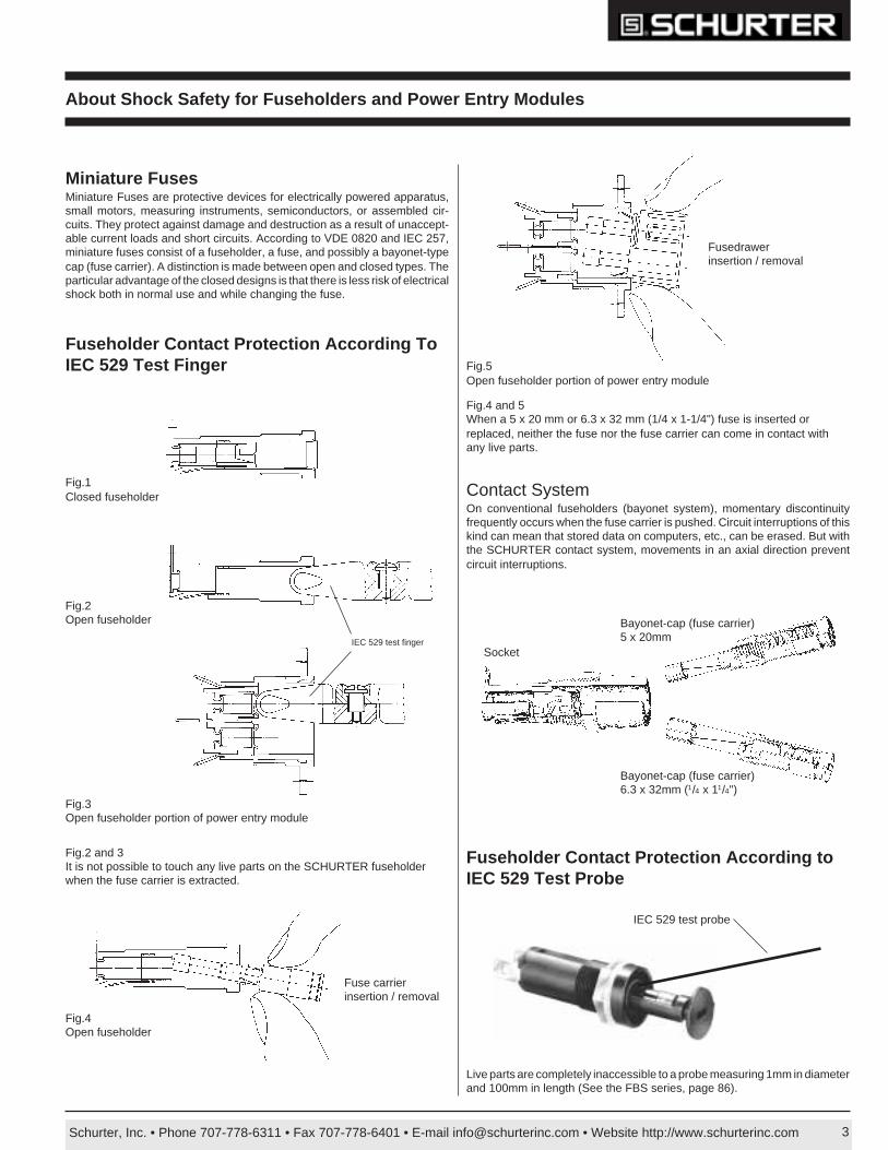
Schurter, Inc. • Phone 707-778-6311 • Fax 707-778-6401 • E-mail [email protected] • Website http://www.schurterinc.com 3
Fig.3Open fuseholder portion of power entry module
Fig.2Open fuseholder
Fuse carrierinsertion / removal
Fig.4Open fuseholder
About Shock Safety for Fuseholders and Power Entry Modules
Fig.1Closed fuseholder Contact System
On conventional fuseholders (bayonet system), momentary discontinuityfrequently occurs when the fuse carrier is pushed. Circuit interruptions of thiskind can mean that stored data on computers, etc., can be erased. But withthe SCHURTER contact system, movements in an axial direction preventcircuit interruptions.
Fig.2 and 3It is not possible to touch any live parts on the SCHURTER fuseholderwhen the fuse carrier is extracted.
Miniature FusesMiniature Fuses are protective devices for electrically powered apparatus,small motors, measuring instruments, semiconductors, or assembled cir-cuits. They protect against damage and destruction as a result of unaccept-able current loads and short circuits. According to VDE 0820 and IEC 257,miniature fuses consist of a fuseholder, a fuse, and possibly a bayonet-typecap (fuse carrier). A distinction is made between open and closed types. Theparticular advantage of the closed designs is that there is less risk of electricalshock both in normal use and while changing the fuse.
Fig.5Open fuseholder portion of power entry module
Fig.4 and 5When a 5 x 20 mm or 6.3 x 32 mm (1/4 x 1-1/4") fuse is inserted orreplaced, neither the fuse nor the fuse carrier can come in contact withany live parts.
Fuseholder Contact Protection According ToIEC 529 Test Finger
Fuseholder Contact Protection According toIEC 529 Test Probe
Fusedrawerinsertion / removal
Bayonet-cap (fuse carrier)5 x 20mm
Bayonet-cap (fuse carrier)6.3 x 32mm (1/4 x 11/4")
SocketIEC 529 test finger
Live parts are completely inaccessible to a probe measuring 1mm in diameterand 100mm in length (See the FBS series, page 86).
IEC 529 test probe
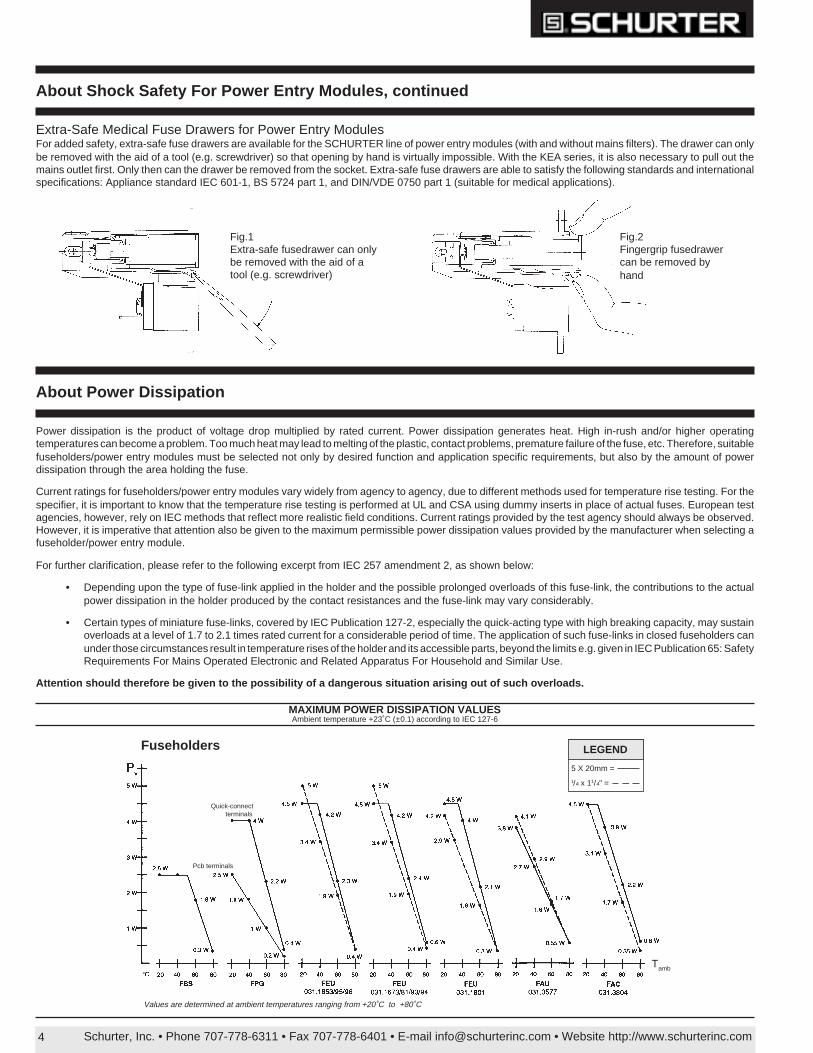
Schurter, Inc. • Phone 707-778-6311 • Fax 707-778-6401 • E-mail [email protected] • Website http://www.schurterinc.com4
Extra-Safe Medical Fuse Drawers for Power Entry ModulesFor added safety, extra-safe fuse drawers are available for the SCHURTER line of power entry modules (with and without mains filters). The drawer can onlybe removed with the aid of a tool (e.g. screwdriver) so that opening by hand is virtually impossible. With the KEA series, it is also necessary to pull out themains outlet first. Only then can the drawer be removed from the socket. Extra-safe fuse drawers are able to satisfy the following standards and internationalspecifications: Appliance standard IEC 601-1, BS 5724 part 1, and DIN/VDE 0750 part 1 (suitable for medical applications).
About Shock Safety For Power Entry Modules, continued
MAXIMUM POWER DISSIPATION VALUESAmbient temperature +23˚C (±0.1) according to IEC 127-6
Power dissipation is the product of voltage drop multiplied by rated current. Power dissipation generates heat. High in-rush and/or higher operatingtemperatures can become a problem. Too much heat may lead to melting of the plastic, contact problems, premature failure of the fuse, etc. Therefore, suitablefuseholders/power entry modules must be selected not only by desired function and application specific requirements, but also by the amount of powerdissipation through the area holding the fuse.
Current ratings for fuseholders/power entry modules vary widely from agency to agency, due to different methods used for temperature rise testing. For thespecifier, it is important to know that the temperature rise testing is performed at UL and CSA using dummy inserts in place of actual fuses. European testagencies, however, rely on IEC methods that reflect more realistic field conditions. Current ratings provided by the test agency should always be observed.However, it is imperative that attention also be given to the maximum permissible power dissipation values provided by the manufacturer when selecting afuseholder/power entry module.
For further clarification, please refer to the following excerpt from IEC 257 amendment 2, as shown below:
• Depending upon the type of fuse-link applied in the holder and the possible prolonged overloads of this fuse-link, the contributions to the actualpower dissipation in the holder produced by the contact resistances and the fuse-link may vary considerably.
• Certain types of miniature fuse-links, covered by IEC Publication 127-2, especially the quick-acting type with high breaking capacity, may sustainoverloads at a level of 1.7 to 2.1 times rated current for a considerable period of time. The application of such fuse-links in closed fuseholders canunder those circumstances result in temperature rises of the holder and its accessible parts, beyond the limits e.g. given in IEC Publication 65: SafetyRequirements For Mains Operated Electronic and Related Apparatus For Household and Similar Use.
Attention should therefore be given to the possibility of a dangerous situation arising out of such overloads.
About Power Dissipation
Fig.1Extra-safe fusedrawer can onlybe removed with the aid of atool (e.g. screwdriver)
Fig.2Fingergrip fusedrawercan be removed byhand
LEGEND
5 X 20mm =
1/4 x 11/4" =
Values are determined at ambient temperatures ranging from +20˚C to +80˚C
Fuseholders
Tamb
Quick-connectterminals
Pcb terminals
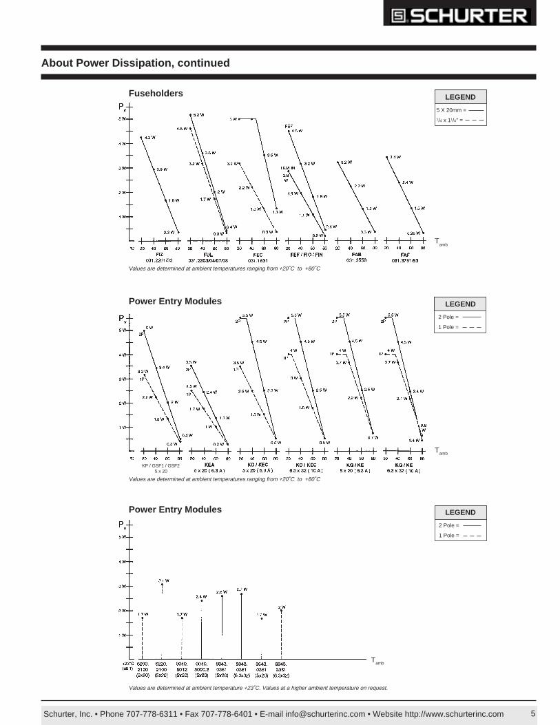
Schurter, Inc. • Phone 707-778-6311 • Fax 707-778-6401 • E-mail [email protected] • Website http://www.schurterinc.com 5
About Power Dissipation, continued
Values are determined at ambient temperature +23˚C. Values at a higher ambient temperature on request.
Values are determined at ambient temperatures ranging from +20˚C to +80˚C
Tamb
Tamb
Tamb
Power Entry Modules
Power Entry Modules
Fuseholders LEGEND
5 X 20mm =
1/4 x 11/4" =
LEGEND
2 Pole =
1 Pole =
LEGEND
2 Pole =
1 Pole =
Values are determined at ambient temperatures ranging from +20˚C to +80˚C
KP / GSF1 / GSF25 x 20