Embed Size (px)
DESCRIPTION
cCNP LAB GUIDE
Citation preview

SWITCH
Lab Guide
Overview This guide presents the instructions and other information concerning the lab activities for the course. Hints are provided at the end of each lab. Ending configurations for each lab are
d of the lab guide.
OuThis g
La
Lab 2-1: Design and implement VLANs, trunks, and EtherChannel
2-2: Troubleshoot Common VLAN Configuration and Security Issues
La
Lab 5-1: Implementing High Availability and Reporting in a Network Design
Campus Network
provided at the en
tline uide includes these activities:
b 1-1: New Hire Test
Lab
Lab 2-3: Implement Private VLANs
b 3-1: Implement Multiple Spanning Tree
Lab 3-2: Implement PVRST+
Lab 3-3: Troubleshoot Spanning Tree Issues
Lab 4-1: Implement Inter-VLAN Routing
Lab 4-2: Troubleshooting Inter-VLAN Routing
Lab 6-1: Implement and Tune HSRP
Lab 6-2: Implementing VRRP
Lab 7-1: Secure Network Switches to Mitigate Security Attacks
Lab 8-1: Plan implementation and Verification of VoIP in a
Lab 9-1: Integrating Wireless in the Campus

2 Implementing Cisco Switched Networks (SWITCH) v1.0 © 2009 Cisco Systems, Inc.
Lr skills from ICND1 and ICND2.
Activity Objective ew. The hiring manager hands you a packet of information,
imply says, “Implement this”. Your task is to plan the impleverifyPackimpleconfiverifiAfter
P
E
D
ab 1-1: New Hire Test Complete this lab activity to confirm and refresh you
You are a CCNA at a job intervileads you to a terminal, and s
mentation, then effectively configure the lab devices as per the given specifications before ing that your configuration fulfills the requirements. Carefully read the Information
et section on the following pages, and proceed through the lab to establish an mentation requirement list, create an implementation and verification plan, and then gure the lab devices as per the specifications. Do not forget to verify and document your cations, as the job interview results will depend on your implementation of the solution. completing this activity, you will be able to meet these objectives:
repare basic configuration templates for your switches.
xplore the remote lab devices connections.
eploy configuration templates to your switches.
Verify your configurations according to the verification plan you created.
© 2009 Cisco Systems, Inc. Lab Guide 3
Intion needed to accomplish in this activity. Read it carefully.
The Inalong
Implementationtwork. It is clearly stated that some settings must be consistent from e next. The following list details the initial configuration
requirmust b
Alde
Te configured.
appearing on the console of
estamp.
time.
st be left to auto.
formation Packet This packet contains the informa
formation Packet describes the requirements common to all devices in the network, with information specific to each device.
Policy The company has a large neone networking device to th
ements for all switches to be connected to the company network. Your configuration e consistent with these requirements:
l switches must have a hostname. Hostnames are unique and must match the switch signation on the network diagram displayed in the following pages.
lnet is allowed to all possible vty interfaces and must be
Initial console access does not need to be protected by any password. Vty access and enable password must be protected by a password.
All passwords are cisco.
Terminal idle timeout must be set to 0 (unlimited).
Logging synchronous should be used so that logging messageseach switch do not disturb commands that are being entered.
Log messages should appear with a tim
Time should be configured on the switches to match your class current
Commands entered incorrectly should not cause the switches to attempt to resolve the entry as a DNS name.
Unless stated otherwise, all interfaces speed and duplex settings mu
All unused interfaces must be set to shutdown.
All devices must have an IP address so that they can be managed remotely.

4 Implementing Cisco Switched Networks (SWITCH) v1.0 © 2009 Cisco Systems, Inc.
Devinformation specific to each device in the network:
ices Information The table provides the
Device name Role IP address Gateway VLAN
ASW1 itch 10.1.1.1/24 51 1 Layer 2 access sw 10.1.1.2
ASW2 Layer 2 ac 52 1 cess switch 10.1.1.2/24 10.1.1.2
DSW1 Layer 3 sw 4 51 1 itch 10.1.1.11/2 10.1.1.2
DSW2 Layer 3 switch 10.1.1.22/24 10.1.1.252 1
CSW1 Layer 3 switch 10.1.1.111/24 10.1.1.251 1
CSW2 Layer 3 sw .1.1.222/24 252 1 itch 10 10.1.1.
R1 Router 0/0: 10.1.1.251/24 1 Fa
R2 Router 0/0: 10.1.1.252/24 1 Fa
During the implementation process, determine, for each switch, which port connects to which neighbo e ports represen h device connection i e gen ports. Each port can represent one or several physical interfaces. When implementing your solution sk 3, use the Ph p table, availabl de, todocument the physical interfaces used in your pod, and report this information on your lab large netwinfor
r. Th ted on eac n the Visual Objective ar eric
in ta ysical Ports Ma e at the end of the lab gui
ork diagram, which is also available at the end of this lab guide. You will use this mation throughout the labs.

Network Diagram
© 2009 Cisco Systems, Inc. All rights reserved. SWITCH v1.0—3
Visual Objective for Lab 1-1: New Hire Test
You write
can use the large version of the Network Diagram available at the end of the lab guide to notes on the diagram.
© 2009 Cisco Systems, Inc. Lab Guide 5

6 Implementing ITCH) v1.0 sco Systems, Inc. Cisco Switched Networks (SW © 2009 Ci
Ce commands that are used in this activity.
ommand List The table describes th
Command Description
confi al Enters global c , from privileged EXEC mode. gure termin onfiguration mode
clockyear
Manually sets the c set hh:mm [:ss] month day lock on the device.
copystart
n running-config up-config
Saves your e tries in the configuration file.
defau[addr
ptional) Spec T
he client. One IP address is required; however, you can specify up to eight IP addresses in one command line. These default
rs are listeeferrednd so
lt-router address ess2 ... address8]
(ODHCP client.t
ifies the IP address of the default router for a he IP address should be on the same subnet as
routemost prrouter, a
d in order of preference; that is, address is the router, address2 is the next most preferred on.
description description Adds a description (up to 240 characters) for an interface.
domain-name domain Specifies the domain name for the client.
duplex {auto | full | half} Sets the duple ace. x parameter for the interf
enabl e privilee password password Sets th ged EXEC mode command interpreter.
exec- Sets erminal ttimeout 0 0 the idle t imeout interval.
exit Exits the current mode.
hostname hostname Manually configures a system name.
intergigab
erfacast Ethernet or Gigabit Ethernet interface installed.
face fastethernet | itethernet slot/port
Enters intwith a F
e configuration mode for a Cisco Catalyst switch
interfaste t | gigab rnet slot/endin
Specifies the raconfigured, and ration mode.
face range therneitethestarting_port - g_port
nge of interfaces (VLANs or physical ports) enters interface-range configu
inter terfacface vlan 1 Enters inwhich the IP in
e configuration mode, and enters the VLAN to formation is assigned.
ip adsubne
Sets the addresdress ip address t-mask
IP s and subnet mask.
ip de Defines a defafault-gateway ult gateway (router) when IP routing is disabled.
linebegin r [endi
difies console, aux, and virtual terminal settings. [aux | console | vty] ning-line-numbeng-line-number]
Mo
loggi Enables messang console ge logging.
loggi Enables synchronous logging of messages. ng synchronous
login bles passw Ena ord checking at login.
no ip Disables DNS-bswitch.
domain-lookup ased hostname-to-address translation on the
no sh inutdown Brings up an terface.
passw gns a password to a terminal or other device on a line. ord password Assi

© 2009 Cisco Systems, Inc. Lab Guide 7
ping ip ess Sends an ICMP ec-addr ho request to ip address.
service timestamps log datetitimezon
Enables time stampsoptions selected
onds relame [msec] [localtime][show-e]
millisecname.
on log messages. Depending on the , the time stamp can include the date, time in tive to the local time-zone, and the time zone
servic ps log uptime
e stathe system was reboo .
e timestam
Enables tim mps on log messages, showing the time since ted
show id] [det
s Cisco Dors, inclu d number,
holdtime settings, capabilities, platform, and port ID.
cdp neighbors [interface-ail]
Displayneighb
iscovery Protocol (CDP) information about ding device type, interface type an
show fastet ort switchport
ini(nonrouting) por
interfaces hernet mod/p
Displays adm strative and operational status of switching ts.
show i Displays interfacnterfaces status e status.
show s your entrunning-config Verifie ries.
shutdo interface. wn Shuts down an
speed auto nonego
e approp rface: Enter 0, 100, or 1000 the interface. The 000 keyword is 000 Mb/s ports.
Enter auto to en te speed with the connected d he 1000
ith the auto keyword, the port autonegotiates only at d spedule
an bedevice that does
{10 | 100 | 1000 | Sets th[10 | 100 | 1000] | tiate}
11
riate speed parameter for the inte to set a specific speed for available only for 10/100/1able the interface to autonegotiaevice. If you use the 10, 100, or t
keywords wthe specifiefor SFP moMb/s but c
eds. The nonegotiate keyword is available only ports. SFP module ports operate only at 1000 configured to not negotiate if connected to a not support autonegotiation.
telnet ip-address Telnets to an IP address.
Job Aids These are the job aids for this lab activity:
Value Location
Blank i t Task mplementation requirements lis 1
Blank implementation plan form Task 2
Blank verification plan form Task 3
Debri ef alternate solutions form End of this lab
Implem equirement hints Hint Section entation r
Impleme Hint Section ntation hints
Verifica ction tion hints Hint Se
Solution Configuration secti nd of the lab guide configuration answer key on at the e

8 Implementing Cisco Switched Networks (SWITCH) v1.0 © 2009 Cisco Systems, Inc.
T
confietc.).Deviimpleeach
ask 1: Establish an Implementation Requirements List The first step in your configuration deployment is to create a list of the items needed to
gure each device (for example, device names, password values, trunk encapsulation types, Use the following table, the initial lab visual objective, the Implementation Policy and ces Information to create an Implementation Requirement list. Include the high-level mentation tasks needed for each device and how to obtain the information required for task. If you are unsure, use the hints information provided at the end of this lab.
Device High Level Task Information Source

© 2009 Cisco Systems, In Lab Guide 9 c.
Ta
configimporthe codetermmove tPackeinform
sk 2: Create an Implementation and Verification Plan The second step in your configuration deployment is to create a task list of each item to
ure on each device and in what order. The Implementation and Verification Plan is very tant, because it enables you to ensure that all requirements are properly configured and in rrect order. The task will help you setup configuration checkpoints. Use the plan to ine how you will verify that each required item was effectively configured. You will o the actual implementation in the next task. Use the following table and the Information
t to create the Implementation and Verification Plan. If you are unsure, use the hints ation provided at the end of this lab.
Complete √
Device ImplementationOrder
Values and items to implement
Verification method and expected results

10 Implementing C sco Switched Ne orks (SWITC ) v1.0 © 2009 Cisco Sy ems, Inc. i tw H st
Complete √
Device Implementation Order
Values and items to implement
Verification method and expected results

© 2009 Cisco Systems, Inc. Lab Guide 11
Talanned the implementation, you are ready
to conOnce yrequirenetwothe hir
sk 3: Implement and Verify Now that you have all of the requirements and have p
nect to the remote lab. You can then implement your solution. Do not forget to save! our solution is implemented, verify that your configuration is working and fulfills the ments specified by the hiring manager. Keep in mind that once you leave the company, a
rk specialist will verify your configuration. Your ability to implement the solution as per ing manager specifications will determine whether or not you get the job.

12 Implementing Cisco Switched Networks (SWITCH) v1.0 © 2009 Cisco Systems, Inc.
Sce to document the details that you think are important to remember.
___
_____
_____
_____
__________________________________________________________________________
_____
_____
_____
_____
__________________________________________________________________________
__________________________________________________________________________
_____
_____
_____
_____
__________________________________________________________________________
_____
_____
_____
_____
__________________________________________________________________________
__________________________________________________________________________
_____
_____
_____
_____
tudent Notes Use the following spa
_______________________________________________________________________
_____________________________________________________________________
_____________________________________________________________________
_____________________________________________________________________
_____________________________________________________________________
_____________________________________________________________________
_____________________________________________________________________
_____________________________________________________________________
_____________________________________________________________________
_____________________________________________________________________
_____________________________________________________________________
_____________________________________________________________________
_____________________________________________________________________
_____________________________________________________________________
_____________________________________________________________________
_____________________________________________________________________
_____________________________________________________________________
_____________________________________________________________________
_____________________________________________________________________
_____________________________________________________________________

© 2009 Cisco Systems, Inc. Lab Guide 13
__________
__________________________________________________________________________
__________
______
______
______
__________________________________________________________________________
__________________________________________________________________________
______
______
______
__________
__________________________________________________________________________
__________
______
______
______
__________________________________________________________________________
__________________________________________________________________________
______
______
______
__________
__________________________________________________________________________
__________
______
________________________________________________________________
________________________________________________________________
____________________________________________________________________
____________________________________________________________________
____________________________________________________________________
____________________________________________________________________
____________________________________________________________________
____________________________________________________________________
________________________________________________________________
________________________________________________________________
____________________________________________________________________
____________________________________________________________________
____________________________________________________________________
____________________________________________________________________
____________________________________________________________________
____________________________________________________________________
________________________________________________________________
________________________________________________________________
____________________________________________________________________

14 Implementing Cisco Switched Networks (SWITCH) v1.0 © 2009 Cisco Systems, Inc.
A
durinother
____ _________________________________________
_____
_____
__________________________________________________________________________
__________________________________________________________________________
_____
_____
_____
_____
__________________________________________________________________________
_____
_____
_____
_____
__________________________________________________________________________
__________________________________________________________________________
_____
_____
_____
_____
__________________________________________________________________________
_____
_____
_____
_____
lternate Resources and Solutions to the One You Used Other groups may use a solution different from yours. Possible solutions will be discussed
g the debrief period after the lab. For your reference, use the following space to document possible solutions.
_____________________________
_____________________________________________________________________
_____________________________________________________________________
_____________________________________________________________________
_____________________________________________________________________
_____________________________________________________________________
_____________________________________________________________________
_____________________________________________________________________
_____________________________________________________________________
_____________________________________________________________________
_____________________________________________________________________
_____________________________________________________________________
_____________________________________________________________________
_____________________________________________________________________
_____________________________________________________________________
_____________________________________________________________________
_____________________________________________________________________
_____________________________________________________________________
_____________________________________________________________________

© 2009 Cisco Systems, Inc. Lab Guide 15
__________
__________________________________________________________________________
__________
______
______
______
__________________________________________________________________________
__________________________________________________________________________
______
______
______
__________
__________________________________________________________________________
__________
______
______
______
__________________________________________________________________________
__________________________________________________________________________
______
______
______
__________
__________________________________________________________________________
__________
________________________________________________________________
________________________________________________________________
____________________________________________________________________
____________________________________________________________________
____________________________________________________________________
____________________________________________________________________
____________________________________________________________________
____________________________________________________________________
________________________________________________________________
________________________________________________________________
____________________________________________________________________
____________________________________________________________________
____________________________________________________________________
____________________________________________________________________
____________________________________________________________________
____________________________________________________________________
________________________________________________________________
________________________________________________________________

16 Implementing Cisco Switched Networks (SWITCH) v1.0 © 2009 Cisco Systems, Inc.
L______________
_____
_____
_____
_____
__________________________________________________________________________
_____
_____
_____
_____
__________________________________________________________________________
__________________________________________________________________________
_____
_____
_____
_____
__________________________________________________________________________
_____
_____
_____
_____
__________________________________________________________________________
__________________________________________________________________________
_____
_____
_____
_____
ab 1-1: Key Commands and Tools Used ____________________________________________________________
_____________________________________________________________________
_____________________________________________________________________
_____________________________________________________________________
_____________________________________________________________________
_____________________________________________________________________
_____________________________________________________________________
_____________________________________________________________________
_____________________________________________________________________
_____________________________________________________________________
_____________________________________________________________________
_____________________________________________________________________
_____________________________________________________________________
_____________________________________________________________________
_____________________________________________________________________
_____________________________________________________________________
_____________________________________________________________________
_____________________________________________________________________
_____________________________________________________________________
_____________________________________________________________________
_____________________________________________________________________

© 2009 Cisco Systems, Inc. Lab Guide 17
Hiu are encouraged to complete the labs using your knowledge. If you need a tip, this section
contai
Lab 1-1 Hint Sheet:
ImTo facilitate the configuration of your network, the first task asks you to create an
list details the elements needed to develop an implemen
nts Yo
ns a series of hints to help you complete the lab.
New Hire Test
plementation Requirements
Implementation Requirements list. Thetation plan. The following is an example of such a list:
Device Implementation Requirement Hint
All switches
t the end of lab guide
Neighbor list and connected ports Show cdp neighbor in command list, port table a
me ram Hostna Network Diag
le, lin oEnabcisco
e vty 0 15 password Implementation p licy section
Login on line vty 0 4 Implementation policy section
VLAN 1 IP Devices Informatio address n section
Gateway matioDevices Infor n section
Idle timeou 0 Implementation policy section t set to
Log messwith a tim
Implementation poages on the console, estamp
licy section
Current time in the class Implementation policy section
No DNS l Implementation poookup licy section
Unused in Show cdp neighbo terfaces shutdown r in command list, port table at the endof lab guide

18 Implementing Cisco Switched Networks (SWITCH) v1.0 © 2009 Cisco Systems, Inc.
Imeate an implementation plan. There are several possible correct solutions.
One appliuniqu“Comfollo
e
n
time
An example of the implementation plan follows.
plementation Plan In task 2, you will cr
possible approach groups items that are common to all switches in a template and then es the template to all switches. You can then configure each switch with items that are e to each device, such as IP addresses or gateway. The common template could be named mon_Template” created in a text editor, copied and pasted as appropriate, and contain the
wing items:
nable password cisco
o ip domain-lookup
line con 0
exec-timeout 0 0
line vty 0 4
password cisco
logging synchronous
login
service timestamp log date
Complete
√
Device Implementation Order
Values and items to implement Step-by-step section No
√ All 2 1 Paste Common_Template.
√ pe 3 r sw 2 Configure hostname.
√ ANper sw 3 Configure VL 1 IP address. 3
√ per sw 4 onfigure switch gateway. 3 C
√ per sw 5 Configure current time and date. 4
√ per sw Verify neighbors6 ports. 5
√ per sw Shutdown unuse 6 7 d ports.
√ per sw Verify connectivit8 y to the gateway. 7
√ per sw 9 Verify configuration. 8

© 2009 Cisco Systems, Inc. Lab Guide 19
Verification Plan Complete
√
Device Values and items to implement
Verification method and expected results
Step-by-step section No
√ All Paste Common_Template
Verify enable password. As this is the first line of the template, its correc
the fi past
properly.
8
t value rst part of ed
indicates that the script was
√ Paste Common_Template
Verify while pastingtemplate that no erreported.
the ror is
2
√ aste Common_Te
Verify the implemeooku of th
template, its succethat the template w
plemlooku
verified using show config or by enterincommand and verifthe switch does noDNS resolution.
Pmplate no ip domain-l
is the last line
ntation of p. As this e ss shows
9
as ented.
p can be running-g a bogus ying that t attempt
successfully imNo ip domain
√ Configure Hostname Prompt should dispswitch name.
lay the 8
√ Configure VLAN 1 IP address
Show ip interface bshould display the address.
rief right
10
√ Configure defaateway
config say
information.
ult Show running-show the gatewg
hould 11
√ onfigure timCdate
e and Show clock. 12
√ Shut unused ports Show cdp neighbodisplay neighbors a
g-confier ports
6 rs to nd ports,
show runninthat the oth
g to verify are shut.
√ Verify connectivity Ping the default gaping should be succ
rificaitches.
should be successful.
teway, essful.
7
As an extra vethe other sw
tion, ping Pings

20 Implementing Cisco Switched Networks (SWITCH) v1.0 © 2009 Cisco Systems, Inc.
StSt e in configuration mode
.
Step 2
Create a notepad text file named Common_template and containing the lines:
n
line con 0
datetime
Paste the Common_Template file content to the console.
e that no error message is reported.
Step 3 Configure the switch hostname and IP information. Use the commands, for example in ASW1:
interface VLAN 1
ip default-gateway 10.1.1.251 end
The information in italics is specific to ASW1. Use the Device Information table in the
Step 4 Configur date on the switch. Use the command clock set, for example:
cloc
ep-by-Step Procedure ep 1 Connect to the switch interfac
Connect to the remote lab.
Access the Switch console.
Enter privilege mode, using enable.
Enter configuration mode, using configure terminal
Paste the Common_Template file
enable password cisco
o ip domain-lookup
exec-timeout 0 0
line vty 0 4
password cisco
logging synchronous
login
service timestamp log
Verify as you past
hostname ASW1
ip address 10.1.1.1 255.255.255.0 exit
Information Packet to find the relevant name and IP information for each switch.
e the current time and
k set 10:06:39 08 Aug 2009

© 2009 Cisco Systems, I Lab Guide 21 nc.
Step 5 Verify neighbor and connecting ports using cdp. For example:
show cdp neighbors Capab T - Trans Bridge, B - Source Route Bridge DevicDSW2 DSW1
In thisconnelocal sinterfa
Step 6 Shutdown
confiinterfa 24
no shinterno shend
This e 1. On each switch, use the show cdp neighbor information to determ es are to be kept enabled.
Step 7 Verify con y:
ping .251 type Sendi!!!!!Success 8 ms
t):
ASW1#ASW1>PasswASW1#
Step 9 Verify no i
getme
ter address
Step 10 Verify IP a
sh ipInter Address OK? Method Status Proto
up
sh ruip de
Step 12 Verify tim
16:26 09
ility Codes: R - Router, S - Switch, H - Host, I - IGMP, r - Repeater, P - Phone
e ID Local Intrfce Holdtme Capability Platform Port ID Fas 0/2 129 R S I WS-C3560- Fas 0/7
Fas 0/1 129 R S I WS-C3560- Fas 0/6
example, the local switch has 2 neighbors, switches DSW2 and DSW1. The local switch cts to switch DSW2 from interface F0/2, which links to switch DSW2 interface f0/7. The witch connects to switch DSW1 from interface f0/1, which links to switch DSW1 ce f0/6.
all ports except links to neighbors:
gure terminal ce rang f0/1 –
shutdown interface f0/2
utdown face f0/1 utdown
xample applies to ASWine which local interfac
wanectivity to the gate
10.1.1escape sequence to abort. ng 5, 100-byte ICMP Echos to 10.1.1.251, timeout is 2 seconds: rate is 100 percent (5/5), round-trip min/avg/max = 1/3/
Step 8 Verify enable password and hostname (using promp
disable enable ord: cisco
-lookup, last line of the template: p domain
there Translating "getmethere" % Unknown command or computer name, or unable to find compu
ddress:
interface brie IP-face
col Vlan1 10.1.1.1 YES manual up
Step 11 Verify gateway:
n | beg ip default fault-gateway 10.1.1.251
e:
show clock :43.545 eastern Sat Jun 6 20

22 Implementing Cisco Switched Networks (SWITCH) v1.0 © 2009 Cisco Systems, Inc.
La
at you learned in the related module.
Activity Obte Inc. to design and configure their branch office Layer 2 network. ady yet, but later on they intend to implement several servers and
addititrunkaskedYou installadditinfrasand Eoptiodocuwill b
P
C
IP
ab 2-1: Design and Implement VLANs, Trunks, nd EtherChannel
Complete this lab activity to practice wh
jective You were hired by NotaRouTheir network is not fully re
onal routers. They know that some devices are supposed to be in VLANs and others in s, but this is where their knowledge ends. They provided you with a cabling plan and you to help them design and configure a typical solution for their network on a test lab.
need to configure the existing network equipment to use the devices once they are ed. Your configuration will be used by the customer as a configuration template as
ional network equipment is purchased. When collecting information about their network tructure, you found that their requirements were all about link types, trunk encapsulation, therChannels. You realize that they have little understanding about more advanced ns such as allowed VLANs, but that they expect you to guide them to provide a mented, functional, and reasonably secured network. After completing this activity, you e able to meet these objectives:
lan a segmented Layer 2 network implementation.
reate a Layer 2 implementation and verification plan.
mplement a full Layer 2 solution including VLANs, trunks, pruning, VLAN Trunking rotocol (VTP), and EtherChannel.

© 2009 Cisco Systems, Inc. Lab Guide 23
Intion needed to accomplish in this activity. Read it carefully.
The Inalong
Implementationer words, keep the configuration from lab 1-1, and
ents.
Not aladditio configuration should include the configuration for the switch ports to these devices. A quick call to the local administrator brings the following eleme
FTcose ext available port for the file server. For example, if the first 4 ports are alr er lab 1-1, configure port 5 for the FTP server and port 6 for the Web
its modes. The local administrator would
runing feature of VTP enabled, and asks you
formation Packet This packet contains the informa
formation Packet describes the requirements common to all devices in the network, with information specific to each device.
Policy This deployment builds on lab 1-1. In othadd the following requirem
l network equipment is installed. The network infrastructure has been installed but not the nal servers or the additional routers. Your
nts:
P, Web servers and additional routers are to be connected later. You are asked to nfigure, as an example, the first available port on switches ASW1 and ASW2 for the FTP rver, and the neady used aft
server. Apply the same logic for the File servers and the additional routers on DSW1 and DSW2. On each switch, the File Server will be on the first available port and the additional router on the next available port.
Several IP addresses are already configured on each router Ethernet interfaces (routers R1 and R2) to your pod, as they need to send traffic to several of your VLAN subnets. You do not need to configure the routers. The switches need to be configured completely, from VLAN database to link type.
During the conversation, you mentioned VTP andlike to try VTP, with the following restrictions:
— All switches should be in transparent mode.
— You should name the domain cisco.
— The administrator does not want the pto prune all unnecessary VLANs from the inter-switch links manually.

24 Implementing Cisco Switched Networks (SWITCH) v1.0 © 2009 Cisco Systems, Inc.
Using this information, your task is to design the VLAN topology with some additional speci
A k topology allows for large redundancy, redundancy is not to be used
Devices In
fications:
lthough the networat this stage. Make sure to disable the links between switches ASW1 and DSW2, ASW2 and DSW1, DSW1 and CSW2, CSW1 and DSW2, CSW1 and router R2, CSW2 and router R1. In other words, the only connection between the upper part of the network (switches ASW1, DSW1 and CSW1) and the lower part of the network (switches ASW2, DSW2 and CSW2) transits through the link between switches CSW1 and CSW2. Use Cisco Discovery Protocol to learn the links between switches and shutdown the ones that are not needed.
For efficiency, several physical connections exist between some of the switches. To simplify the network administration, group these physical links into logical links wherever possible. Where two 100 Mbps links are grouped, use an IEEE grouping protocol, and make sure that one end actively tries to negotiate the virtual link creation, while the other only responds to solicitations and does not actively try to create the link. Where four 100 Mbps are to be grouped, create the virtual link unconditionally without using any negotiation protocol. Use the description feature on each virtual links to reflect which devices they connect. Also use the table in devices information.
Client PC in VLAN 3 and client PC in VLAN 4 need to receive their IP address from routers R1 and R2. R1 and R2 are preconfigured.
formation The table provides the information specific to each switch in the network. This information is the same as in lab 1-1:
Device name Role IP address Gateway VLAN
ASW1 Layer 2 access switch 10.1.1.1/24 10.1.1.251 1
ASW2 Layer 2 access switch 10.1.1.2/24 10.1.1.252 1
DSW1 Layer 3 switch 10.1.1.11/24 10.1.1.251 1
DSW2 Layer 3 switch 10.1.1.22/24 10.1.1.252 1
CSW1 Layer 3 switch 10.1.1.111/24 10.1.1.251 1
CSW2 Layer 3 switch 10.1.1.222/24 10.1.1.252 1
R1 Router Fa0/0: 10.1.1.251/24 1
R2 Router Fa0/0: 10.1.1.252/24 1

© 2009 Cisco Systems, Inc. Lab Guide 25
The table below provides information about the devices connected or to be connected to the netwoabove
rk. Use the space to document which port in your pod each device should connect per the policy and the previous lab information:
Device Role Network location
VLAN Physical port in your lab
CLT1 Client station ASW1 P3 3
CLT2 Client station ASW2 P3 4
NR1 Router DSW1 P7 trunk
NR2 Router DSW2 P7 trunk
WEB1 Web Server ASW1 P5 11
WEB2 Web Server ASW2 P5 12
FTP1 FTP Server ASW1 P4 63
FTP2 FTP Server ASW2 P4 64
FILE1 File Server DSW1 P6 65
FILE2 File Server DSW2 P6 66

26 Implementing Cisco Switched Networks (SWITCH) v1.0 © 2009 Cisco Systems, Inc.
Some lpossineedeyou hbund
inks between switches should be bundled together. The following table shows all ble numbering convention for these link bundles. Note that NOT all of these numbers are d. You should use cdp to determine which links between switches can be bundled. Once ave determined which links has to bundle, use the following table to apply the right le number:
Device Link to If used, bundle number should be:
ASW1 W2 10 AS
ASW1 DSW1 11
ASW1 SW2 12 D
ASW2 ASW1 10
ASW2 DSW1 11
ASW2 SW2 12 D
DSW1 1 11 ASW
DSW1 2 12 ASW
DSW SW2 21 1 D
DSW SW1 31 1 C
DSW SW2 32 1 C
DSW2 ASW1 11
DSW2 ASW2 12
DSW2 DSW1 21
DSW2 CSW1 31
DSW2 CSW2 32
CSW SW1 31 1 D
CSW1 DSW2 32
CSW SW2 33 1 C
CSW2 DSW1 31
CSW2 DSW2 32
CSW2 CSW1 33

Network Diagram
© 2009 Cisco Systems, Inc. All rights reserved. SWITCH v1.0—4
Visual Objective for Lab 2-1: Design and Implement VLANs, Trunk and EtherChannel
© 2009 Cisco Systems, Inc. Lab Guide 27

28 Implementing C orks (SWITCH) v1.0 isco Switched Netw © 2009 Cisco Systems, Inc.
Ce commands that are used in this activity.
Configuration Commands
ommand List The table describes th
Command Description
inter ernet | gigab slot/port
Enters interfac ode for a Cisco Catalyst switch with a Fast Eth interface installed.
face fastethitethernet
e configuration mernet or Gigabit Ethernet
interfastegigabslot/endin
ngface range thernet | itethernet
Selects a ra
starting_port - g_port
e of interfaces to configure.
name Specifies a name for a VLAN for either VLAN database or VLAN uration mode.
vlan-name config
no in n-id type
Disables a VLAN interface. terface vlan vla
show -id switchport
Displays the sinterface interface witch port configuration of the interface.
show rinterface trunk Displays the t unk configuration of the interface.
show Displays VLAN information. vlan
show Tvtp status Shows the V P configuration.
shutd Shuts down or enables an interface. own/no shutdown
switcvlan-
ifies the ding.
hport access vlan Spectrunkid
efault VLAN, which is used if the interface stops
switc cess Puts the interfa nd negotiates to c
hport mode ac ce into permanent nontrunking mode aonvert the link into a nontrunk link.
switc the interfa tes to rt the lin
hport mode trunk Puts conve
ce into permanent trunking mode and negotiak into a trunk link.
switc TPhport nonegotiate Turns off D negotiation.
switc allowed vlan
Configures the s allowed on the trunk. hport trunk remove vlan-list
list of VLAN
switcencapsulation dot1q
802.hport trunk Specifies 1Q encapsulation on the trunk link.
switcencapsulation isl
s ISL ehport trunk Specifie ncapsulation on the trunk link.
inter changroupdesir
ionall ol (PAgP). mod ating state in
ter
n either the desirable or auto mode. When desirable is enab d, silent
face interface-id nel-group channel-
UnconditDesirable
-number mode able
which the insending PAgP group i
le
y enables Port Aggregation Protoce places an interface into a negotiface initiates negotiations with other interfaces by packets. A channel is formed with another port
operation is the default.
show inter
lays interfacrunning-config face interface-id
Disp e-specific configuration information.
vtp d Sets the VTP omain domain-name domain name.
vtp mserve
s the VTP mode. ode [ client | Setr | transparent ]

© 2009 Cisco Systems, Inc. Lab Guide 29
Johe job aids for this lab activity:
b Aids These are t
Value Location
Blank im ation requirements list Task 1 plement
Blank im plementation plan form Task 2
Blank verific Task 3 ation plan form
Debrief altern End of this lab ate solutions form
Implem Hint Section entation requirement hints
Implem Hint Section entation hints
Verifica int Section tion hints H
Solution c Configuration sectio b guide onfiguration answer key n at the end of the la

30 Implementing Cisco Switched Networks (SWITCH) v1.0 © 2009 Cisco Systems, Inc.
T
confiUse tInforimpleeach
ask 1: Establish an Implementation Requirements List The first step in your configuration deployment is to create a list of the items needed to
gure each device (for example allowed VLANs, VTP role, trunk encapsulation types, etc.). he following table, the initial lab visual objective, the Implementation Policy and Devices mation to create an Implementation Requirement list. Include the high-level mentation tasks needed for each device and how to obtain the information required for task. If you are unsure, use the hints information provided at the end of this lab.
Device High Level Task Information Source

© 2009 Cisco Systems, In Lab Guide 31 c.
Device High Level Task Information Source

32 Implementing C o Switched Networks (SWITC © 2009 Cisco Syisc H) v1.0 stems, Inc.
To heyou w
lp you decide on the VLAN implementation, use the following table to list the VLANs ill need and decide on which devices they should be configured:
VLAN Number
VLAN Name Configure on switches:
Task 2: Create an Implementation and Verification Plan The second step in your configuration deployment is to create a task list of each item to config e on each device and in what order. The Implementa on and Verification Plan is very important, because it enables you to ensure that all requirements are properly configured and in the correct order. The task will help you setup configuration checkpoints. Use the plan to determine how you will verify that each required item was effectively configured. You will
ur ti
move to the actual implementation in the next task. Use the following table and the Information Packet to create the Implementation and Verification Plan. If you are unsure, use the hints information provided at the end of this lab.
Complete √
Device Implementation Order
Values and items to implement
Verification method and expected results

© 2009 Cisco Systems, Inc. Lab Guide 33
Complete √
Device ImplementationOrder
Values and items to implement
Verification method and expected results

34 Implementing C sco Switched Ne orks (SWITC ) v1.0 © 2009 Cisco Sy ems, Inc. i tw H st
Complete √
Device Implementation Order
Values and items to implement
Verification method and expected results

© 2009 Cisco Systems, Inc. Lab Guide 35
Complete √
Device ImplementationOrder
Values and items to implement
Verification method and expected results

36 Implementing Cisco Switched Networks (SWITCH) v1.0 © 2009 Cisco Systems, Inc.
Complete √
Device Implementation Order
Values and items to implement
Verification method and expected results
© 2009 Cisco Systems, Inc. Lab Guide 37
Talanned the implementation, you are ready
to conOnce yrequirewill usapply one yoconduyou ar
sk 3: Implement and Verify Now that you have all of the requirements and have p
nect to the remote lab. You can then implement your solution. Do not forget to save! our solution is implemented, verify your configuration is working and fulfills the ments specified by the company. Keep in mind that once you leave the company, they e your configuration as a whitepaper to implement their network. The company will your configuration, without modification, to connect any device of the same type as the u configured for each port. Use the previous table to document the verifications you cted to ensure that your solution is complete. Hints are available at the end of this lab if e unsure about the verification steps.

38 Implementing Cisco Switched Networks (SWITCH) v1.0 © 2009 Cisco Systems, Inc.
Sce to document the details that you think are important to remember.
___
_____
_____
_____
__________________________________________________________________________
_____
_____
_____
_____
__________________________________________________________________________
__________________________________________________________________________
_____
_____
_____
_____
__________________________________________________________________________
_____
_____
_____
_____
__________________________________________________________________________
__________________________________________________________________________
_____
_____
_____
_____
tudent Notes Use the following spa
_______________________________________________________________________
_____________________________________________________________________
_____________________________________________________________________
_____________________________________________________________________
_____________________________________________________________________
_____________________________________________________________________
_____________________________________________________________________
_____________________________________________________________________
_____________________________________________________________________
_____________________________________________________________________
_____________________________________________________________________
_____________________________________________________________________
_____________________________________________________________________
_____________________________________________________________________
_____________________________________________________________________
_____________________________________________________________________
_____________________________________________________________________
_____________________________________________________________________
_____________________________________________________________________
_____________________________________________________________________

© 2009 Cisco Systems, Inc. Lab Guide 39
__________
__________________________________________________________________________
__________
______
______
______
__________________________________________________________________________
__________________________________________________________________________
______
______
______
__________
__________________________________________________________________________
__________
______
______
______
__________________________________________________________________________
__________________________________________________________________________
______
______
______
__________
__________________________________________________________________________
__________
______
________________________________________________________________
________________________________________________________________
____________________________________________________________________
____________________________________________________________________
____________________________________________________________________
____________________________________________________________________
____________________________________________________________________
____________________________________________________________________
________________________________________________________________
________________________________________________________________
____________________________________________________________________
____________________________________________________________________
____________________________________________________________________
____________________________________________________________________
____________________________________________________________________
____________________________________________________________________
________________________________________________________________
________________________________________________________________
____________________________________________________________________

40 Implementing Cisco Switched Networks (SWITCH) v1.0 © 2009 Cisco Systems, Inc.
A
durinother
____ _________________________________________
_____
_____
__________________________________________________________________________
__________________________________________________________________________
_____
_____
_____
_____
__________________________________________________________________________
_____
_____
_____
_____
__________________________________________________________________________
__________________________________________________________________________
_____
_____
_____
_____
__________________________________________________________________________
_____
_____
_____
_____
lternate Resources and Solutions to the One You Used Other groups may use a solution different from yours. Possible solutions will be discussed
g the debrief period after the lab. For your reference, use the following space to document possible solutions.
_____________________________
_____________________________________________________________________
_____________________________________________________________________
_____________________________________________________________________
_____________________________________________________________________
_____________________________________________________________________
_____________________________________________________________________
_____________________________________________________________________
_____________________________________________________________________
_____________________________________________________________________
_____________________________________________________________________
_____________________________________________________________________
_____________________________________________________________________
_____________________________________________________________________
_____________________________________________________________________
_____________________________________________________________________
_____________________________________________________________________
_____________________________________________________________________
_____________________________________________________________________

© 2009 Cisco Systems, Inc. Lab Guide 41
__________
__________________________________________________________________________
__________
______
______
______
__________________________________________________________________________
__________________________________________________________________________
______
______
______
__________
__________________________________________________________________________
__________
______
______
______
__________________________________________________________________________
__________________________________________________________________________
______
______
______
__________
__________________________________________________________________________
__________
________________________________________________________________
________________________________________________________________
____________________________________________________________________
____________________________________________________________________
____________________________________________________________________
____________________________________________________________________
____________________________________________________________________
____________________________________________________________________
________________________________________________________________
________________________________________________________________
____________________________________________________________________
____________________________________________________________________
____________________________________________________________________
____________________________________________________________________
____________________________________________________________________
____________________________________________________________________
________________________________________________________________
________________________________________________________________

42 Implementing Cisco Switched Networks (SWITCH) v1.0 © 2009 Cisco Systems, Inc.
L______________
_____
_____
_____
_____
__________________________________________________________________________
_____
_____
_____
_____
__________________________________________________________________________
__________________________________________________________________________
_____
_____
_____
_____
__________________________________________________________________________
_____
_____
_____
_____
__________________________________________________________________________
__________________________________________________________________________
_____
_____
_____
_____
ab 2-1: Key Commands and Tools Used ____________________________________________________________
_____________________________________________________________________
_____________________________________________________________________
_____________________________________________________________________
_____________________________________________________________________
_____________________________________________________________________
_____________________________________________________________________
_____________________________________________________________________
_____________________________________________________________________
_____________________________________________________________________
_____________________________________________________________________
_____________________________________________________________________
_____________________________________________________________________
_____________________________________________________________________
_____________________________________________________________________
_____________________________________________________________________
_____________________________________________________________________
_____________________________________________________________________
_____________________________________________________________________
_____________________________________________________________________
_____________________________________________________________________

© 2009 Cisco Systems, Inc. Lab Guide 43
Hiu are encouraged to complete the labs using your knowledge. If you need a tip, this section
contai
Lab 2-1 Hint Sheet: hannel
Imork, the first task asks you to create an
list details the elements needed to develop an implem
nts Yo
ns a series of hints to help you complete the lab.
Design and Implement VLANs, Trunks, and EtherC
plementation Requirements To facilitate the configuration of your netwImplementation Requirements list. The
entation plan. The following is an example of such a list:
Device Implementation Requirement Hint
ASW1 Port to CLT1 in VLAN 3. Implementation Policy
il Implementation Policy First ava able port in VLAN 63.
Second available port in VLAN 11. Implementation Policy
DS hannel). Implementation PolicyInformation
Link to W1 in trunk mode (verify Etherc , Devices
Allow VLAN Implementation Policys 1, 3, 11 and 63 on trunk. Information
, Devices
Link to DS yW2 in trunk mode (verify Etherchannel). Implementation PolicInformation
, Devices
Allow VLANs 1, 3, 11 and 63 on trunk. Implementation Policy, Devices ation Inform
VTP transparent domain cisco password cisco. Implementation Policy
Configure y and shut port(s) to ASW2. Implementation Polic
ASW2 Port to CLT2 in VLAN 4. Implementation Policy
First available port in VLAN 64. Implementation Policy
Second available port in VLAN 12. Implementation Policy
Link to DSW2 in trunk mode (verify Etherchannel). Implementation Policy, Devices Information
Allow VLANs 1, 4, 12 and 64 on trunk. Implementation Policy, Devices Information
Link to DS . W1 in trunk mode (verify Etherchannel) Implementation Policy, Devices Information
Allow VLANs 1, 4, 12 and 64 on trunk. Implementation Policy, Devices Information
VTP transparent domain cisco, with password cisco.
Implementation Policy
Configure and shut port(s) to ASW1. Implementation Policy
DSW1 VTP transparent, domain cisco password cisco. Implementation Policy
First avail yable port in VLAN 65. Implementation Polic
Second available port in trunk. Implementation Policy

44 Implementing Cisco Switched Networks (SWITCH) v1.0 © 2 s, Inc. 009 Cisco System
Device Implementation Requirement Hint
VLANs 1, 3, 4, 11, 12, 63, 64, 65 and 66 allowed on trunk
Implementation Policy, Devices . Information
Link to D mode (verify Etherchannel). Implementation PolicInformation
SW2 in trunk y, Devices
VLANs 1on trunk.
liInformation
, 3, 4, 11, 12, 63, 64, 65 and 66 allowed Implementation Po cy, Devices
Configur olie and shut port(s) to DSW2. Implementation P cy
Link to A mode (verify Etherchannel). Implementation Policformation
SW1 in trunk y, Devices In
VLANs 1, 3, 11 and 63 allowed on trunk. Implementation PolicInformation
y, Devices
Link to ASW2 in trunk mode (verify Etherchannel). Implementation Poliction
y, Devices Informa
VLANs 1, 4, 12 and 64 allowed on trunk. Implementation PolicInformation
y, Devices
Configur lie and shut port(s) to ASW2. Implementation Po cy
Link to CSW1 in trunk mode (verify Etherchannel). Implementation Policy, Devices tion Informa
VLANs 1, 3, 4, 11, 12, 63, 64, 65 and 66 allowed on trunk
Implementation Policformation . In
y, Devices
Link to CSW2 in trunk mode (verify Etherchannel). Implementation Policy, Devices Information
VLANs 1, 3, 4, 11, 12, 63, 64, 65 and 66 allowed on trunk
Implementation Polic. Information
y, Devices
Configur rt(s) to CSW2. Implementation Police and shut po y
Link to D liSW2 in trunk mode (verify Etherchannel). Implementation PoInformation
cy, Devices
VLANs 1, 3, 4, 11, 12, 63, 64, 65 and 66 allowed on trunk
Implementation Policy, Devices . Information
Configur rt(s) to DSW2. Implementation Police and shut po y
DSW2 VTP transparent, domain cisco pass cisco. Implementation Policy
First available port in VLAN 66. Implementation Policy
Second available port in trunk. Implementation Policy
VLANs 1, 3, 4, 11, 12, 63, 64, 65 and 66 allowed on trunk.
Implementation Policy, Devices Information
Link to DSW1 in trunk mode (verify Etherchannel). Implementation Policy, Devices Information
VLANs 1, 3, 4, 11, 12, 63, 64, 65 and 66 allowed on trunk.
Implementation Policy, Devices Information
Configure and shut port(s) to DSW1. Implementation Policy
Link to A l). SW1 in trunk mode (verify Etherchanne Implementation Policy, Devices Information
VLANs 3, 11 and 63 allowed on trunk. Implementation Policy, Devices Information

© 2009 Cisco Systems, Inc. 45 Lab Guide
Device Implementation Requirement Hint
Link to ASW2 in trunk mode (verify Etherchannel). Implementation Policy, Devices Information
VLANs 1, 4, 12 and 64 allowed on trunk. Implementation Policy, Devices Information
Configure and shut port(s) to ASW2. Implementation Policy
Link to CSW1 in trunk mode (verify Etherchannel). Implementation Policy, Devices Information
VLANs 1, 3, 4, 11, 12, 63, 64, 65 and 66 allowed on trunk.
Implementation Policy, Devices Information
Link to CSW2 in trunk mode (verify Etherchannel). Implementation Policy, Devices Information
VLANs 1, 63, 64, 65 and 66 allowed 3, 4, 11, 12,on trunk.
Implementation Policy, Devices Information
Configure and shut port(s) to CSW2. Implementation Policy
Link to DSW2 in trunk mode (verify Etherchannel). Implementation Policy, Devices Information
VLANs 1, 3, 4, 11, 12, 63, 64, 65 and 66 allowed on trunk.
Implementation Policy, Devices Information
Configure and shut port(s) to DSW2. Implementation Policy
CSW1 VTP transparent, domain cisco password cisco. Implementation Policy
Link to R1 in trunk. Network Diagram
VLANs 1, d 65 allowed on trunk. Implementation Policy 3, 11, 63 an , Devices Information
Link to R2 work Diagram in trunk. Net
1, licyInformation
VLANs 4, 12, 64 and 66 allowed on trunk. Implementation Po , Devices
Link to DSW2 in trunk mode (verify Etherchannel). Implementation Policy, Devices Information
VLANs 1, 3, 4, 11, 12, 63, 64, 65 and 66 allowed on trunk.
Implementation PolicyInformation
, Devices
Configure and shut port(s) to DSW2. Implementation Policy
Link to DS on PolicyInformation
W1 in trunk mode (verify Etherchannel). Implementati , Devices
VLANs 1,on trunk.
yInformation
3, 4, 11, 12, 63, 64, 65 and 66 allowed Implementation Polic , Devices
Link to CS licyW2 in trunk mode (verify Etherchannel). Implementation PoInformation
, Devices
VLANs 1, 3, 64, 65 and 66 allowed on trunk.
Implementation Policyrmation
4, 11, 12, 63, , Devices Info
CSW2 VTP transparent, domain cisco password cisco. Implementation Policy
Link to R1 in trunk. Network Diagram
VLANs 1, 3, 11, 63 and 65 allowed on trunk. Implementation Policy, Devices Information
Link to R2 in trunk. Network Diagram

46 Implementing Cisco Switched Networks (SWITCH) v1.0 © 2009 Cisco Systems, Inc.
Device Implementation Requirement Hint
VLANs 1, 4, 12, 64 and 66 allowed on trunk. Implementation Policy, Devices Information
Link to DSW1 in trunk mode (verify Etherchannel). Implementation Policy, Devices Information
VLANs 1, 3, 4, 11, 12, 63, 64, 65 and 66 allowed on trunk.
Implementation Policy, Devices Information
Configure and shut port(s) to DSW1. Implementation Policy
Link to D mode (verify Etherchannel). SW2 in trunk Implementation Policy, Devices Information
VLANs 1, 3, 4, 11, 12, 63, 64, 65 and 66 allowed on trunk.
Implementation Policy, Devices Information
Link to CSW1 in trunk mode (verify Etherchannel). Implementation Policy, Devices Information
VLANs 1 , 63, 64, 65 and 66 allowed , 3, 4, 11, 12on trunk.
Implementation Policy, Devices Information

© 2009 Cisco Systems, Inc. Lab Guide 47
Implan. There are several possible correct solutions.
One papplieuniquenamed contai
Vt
vt
CSW1, CSW2, DSW1 and DSW2. ASW1 and ASW2 req ou may want to configure them manually. An
ification Plan follows.
lementation and Verification Plan In task 2, you will create an implementation p
ossible approach groups items that are common to all switches in a template and then s the template to all switches. You can then configure each switch with items that are to each device, interface mode or EtherChannel links. The common template could be “Common_Template” just like in the previous lab: For this lab, the template could
n the following items:
p mode transparent
p domain cisco
vtp password cisco
vlan 3,4,11,12,63-66
You can implement this template to uire specific VLAN configuration, so y
example of the Implementation and Ver
Complete √
Device Imple-menta-tion Order
Values and items to implement
Verification method and expected results
Step-by-step No
PC Tem
us (shoomain c
sword cisco).
CSW1 1 aste ommon_ plate.
Show vtp stattransparent, dpas
ws isco,
2
2 C e trunk link to R1, a ANs 1, 3, 11, 6
Show run interface to R1, trunk, allowed VLANs 1, 3, 4, 11, 12, 63, 64, 65 and 66, show interface trunk.
4 onfigurllowed VL3, 65.
3 C kallowed VLANs64, 66.
erface tod VLANs
11, 12, 63, 64, 65 and.
onfigure trun link to R2, 1, 4, 12,
Show run inttrunk, allowe
R2, 1, 3, 4, 66,
4
show interface trunk
4 (Verify if needeconfigure EtheCSW2, on if 4 l if 2 links.
el sd and) rChannel to inks, LACP
Show etherchannactive or on.
tatus 5
C igure trunallo d VLANs12, 63, 64, 65
toNs
5 andshow interface trunk.
5 onfwe
k to CSW2, 1, 3, 4, 11,
and 66.
Show run interface trunk, allowed VLA11, 12, 63, 64, 6
CSW2, 1, 3, 4, 66,
6
6 (Verify if needed and) c gure EtheD 2, on if 4 lif 2 links.
Show etherchannel status 5 onfiSW
rChannel to inks, LACP
active or on.
7 Configure trunallowed VLANs 1, 3, 4, 11, 12, 63, 64, 65 Shut link down
Show run interface to DSW2, trunk allowed VLANs 1, 3, 4,
nd
8 k to DSW2,
and 66. .
11, 12, 63, 64, 65 ashut.
66, link
8 (Verify if needeconfigure EtherChannel to DSW1, on if 4 links, LACP i s.
nnel sactive or on.
d and) Show ethercha
f 2 link
tatus 5

48 Implementing Cisco Switched Networks (SWIT ) v1.0 © 200CH 9 Cisco Systems, Inc.
Complete √
Device Imple-menta-tion Order
Values and items to implement
Verification method and expected results
Step-by-step No
9 Configure trunk to DSW1, allowed VLANs 1, 3, 4, 11,
63, 64, 65
Show run interface to CSW2, trunk, allowed 1, 3, 4, 11, 12,
, s
7
12, and 66. 63, 64, 65 and 66interface trunk.
how
CSW2 1 Paste Common_Template.
Show vtp status (shows transparent, domain cisco, password cisco).
9
2 Configure trunk link to R1, allowed VLANs 1, 3, 11, 63, 65.
Show run interface to R1, trunk, allowed VLANs 1, 3, 4, 11, 12, 63, 64, 65 and 66, show interface trunk.
9
3 Configure trunk link to R2, allowed VLANs 1, 4, 12, 64, 66.
Show run interface to R2, trunk, allowed VLANs 1, 3, 4, 11, 12, 63, 64, 65 and 66, show interface trunk.
9
4 (Verify if needed and) configure EtherChannel to CSW1, on if 4 links, LACP if 2 links.
Show etherchannel status active or on.
9
5 Configure trunk to CSW1, allowed VLANs 1, 3, 4, 11, 12, 63, 64, 65 and 66.
Show run interface to CSW1, trunk, allowed VLANs 1, 3, 4, 11, 12, 63, 64, 65 and 66, show interface trunk.
9
6 (Verify if needed and) configure Eth erChannel toDSW1, on if 4 links, LACP if 2 links.
Show etherchannel status active or on.
9
7 Configure trunk to DSW1, allowed VLANs 1, 3, 4, 11, 12, 63, 64, 65 and 66. Shut link down.
Show run interface to DSW2, trunk allowed VLANs 1, 3, 4, 11, 12, 63, 64, 65 and 66.
9
8 (Verify if needed and) configure EtherChannel to DSW2, on if 4 links, LACP if 2 links.
Show etherchannel status active or on.
9
9 Configure trunk to DSW2, allowed VLANs 1, 3, 4, 11, 12, 63, 64, 65 and 66.
Show run interface to CSW2, trunk, allowed 1, 3, 4, 11, 12, 63, 64, 65 and 66, link shut.
9
DSW1 1 Paste Common_Template,
nge VTP er.
vtp status (shows transparent, domain cisco,
co).
10
chaserv
mode to password cis
Show
2 (Verify if needconfigure Eth CSW1, on if 4 links, LACP
links.
l status active or on.
11/12 ed and) erChannel to
Show etherchanne
if 2
3 Configure truallowed VLAN12, 63, 64, 65 and 66.
t
11, 12, 63, 64, 65 and 66, show interface trunk
nk to CSW1, s 1, 3, 4, 11,
Show run interfacetrunk, allowed VLAN
o CSW1, s 1, 3, 4,
14
.

© 2009 Cisco Systems, Inc. Lab Guide 49
Complete √
Device Imple-menta-tion Order
Values and items to implement
Verification method and expected results
Step-by-step No
4 (Verify if needed and) configure EtherChannel to C 2, on if 4 li s.
Show etherchannel status active or on.
11/12
SWf 2 link
inks, LACP
5 Configure trunallowed VLANs12, 63, 64, 65 and 6Shut link down
to CSW2, trunk, allowed VLANs 1, 3, 4, 11, 12, 63, 64, 65 and 66. Link
15 k to CSW2, 1, 3, 4, 11,
6.
Show run interface
. shut.
6 (Verify if needeconfigure EtheDSW2, on if 4 lif 2 links.
d and) rChannel to inks, LACP
Show etherchannel sactive or on.
tatus 11/12
C igure trunallowed VLANs12, 63, 64, 65 Shut link down
os
nd 66. Link
7 onf k to DSW2, 1, 3, 4, 11,
and 66. .
Show run interface ttrunk, allowed VLAN11, 12, 63, 64, 65 ashut.
DSW2, 1, 3, 4,
13
8 (Verify if needec gure EtheASW1, on if 4 lif 2 links.
l std and) rChannel to inks, LACP
Show etherchanneactive or on. onfi
atus 11/12
9 Configure trunkallo d VLANs 1, 63 and 65.
run interface toVLANsw inter
16 to ASW1, Show we 3, 11, trunk, allowed
63 and 65, shotrunk.
ASW1, 1, 3, 11, face
10 (Verify if needeconfigure EtheASW2, on if 4 linki s.
status active or on.
11/12 d and) rChannel to
Show etherchannel
s, LACP f 2 link
11 Configure trunkallowed VLANs64 and 66.
e torunk, allowed VLANs
64 and 66, show inter
to ASW2, 1, 2, 12,
Show run interfact
ASW1, 1, 2, 12, face
16
trunk.
12 C gure first port in access VLAN 65.
n onfi available mode,
First available port imode, VLAN 65.
access 18
13 Configure second a ble port ia d VLANs12, 63, 64, 65
Second available port in trunk, , h
19 vailallowe
n trunk, 1, 3, 4, 11,
and 66.
allowed VLANs 1, 363, 64, 65 and 66, sinterface trunk.
4, 11, 12, ow
DSW2 1 Paste Common_Template.
Show vtp status (shows transparent, domain cisco, password cisco).
21
2 (Verify if needed and) configure EtherChannel to CSW2, on if 4 links, LACP i ks. f 2 lin
Show etherchannel status active or on.
21
3 Configure trunk to CSW2, allowed VLANs 1, 3, 4, 11, 12, 63, 64, 65 and 66.
Show run interface to CSW2, trunk, allowed VLANs 1, 3, 4, 11, 12, 63, 64, 65 and 66, show interface trunk.
21

50 Implementing Cisco Switched Networks (SWIT ) v1.0 © 200CH 9 Cisco Systems, Inc.
Complete √
Device Imple-menta-tion Order
Values and items to implement
Verification method and expected results
Step-by-step No
4 (Verify if needed and) configure EtherChannel to CSW1, on if 4 links, LACP if 2 links.
Show etherchannel status active or on.
21
5 Configure trunk to CSW1, allowed VLAN s 1, 3, 4, 11,12, 63, 64, 65 and 66. Shut link down.
Show run interface to CSW1, trunk, allowed VLANs 1, 3, 4, 11, 12, 63, 64, 65 and 66. Link shut.
21
6 (Verify if needed and) configure EtherChannel to DSW1, on if 4 links, LACP if 2 links.
Show etherchannel status active or on.
21
7 Configure trunk to DSW1, allowed VLANs 1, 3, 4, 11, 12, 63, 64, 65 and 66. Shut link down.
Show run interface to DSW1, trunk, allowed VLANs 1, 3, 4, 11, 12, 63, 64, 65 and 66. Link shut.
21
8 (Verify if needed and) configure EtherChannel to ASW2, on if 4 links, LACP if 2 links.
Show etherchannel status active or on.
21
9 Configure trunk to ASW2, allowed VLANs 1, 2, 12, 64 and 66.
Show run interface t , o ASW1trunk, allowed VLANs 1, 3, 11, 63 and 65, show interface trunk.
21
10 (Verify if needed and) configure Eth erChannel toASW1, on if 4 links, LACP if 2 links.
Show etherchannel status active or on.
21
11 Configure trunk to ASW1, allowed VLANs 1, 3, 11, 63 and 65.
Show run interface to ASW1, trunk, allowed VLANs 1, 2, 12, 64 and 66, show interface trunk.
21
12 Configure first available port in access mode, VLAN 66.
First available port in access mode, VLAN 66.
21
13 Configure second available port in trunk, allowed VLANs 1, 3, 4, 11, 12, 63, 64, 65 and 66.
Second available port in trunk, allowed VLANs 1, 3, 4, 11, 12, 63, 64, 65 and 66, show interface trunk.
21
ASW1 1 VTP mode transparent, domain and password
.
Show vtp status, tra domain and password .
22
cisco
nsparent, cisco
2 (Verify if needconfigure EthDSW1, on if 4 links, LACP
ks.
hannel active or on.
ed and) erChannel to
Show etherc
if 2 lin
status 23
3 Configure truallowed VLAN63 and 65.
tN
int
nk to DSW1, s 1, 3, 11,
Show run interfacetrunk, allowed VLA63 and 65, showtrunk.
o DSW1, s 1, 3, 11,
erface
24

© 2009 Cisco Systems, Inc. Lab Guide 51
Complete √
Device Imple-menta-tion Order
Values and items to implement
Verification method and expected results
Step-by-step No
4 (Verify if needed and) configure EtherChannel to D 2, on if 4 li s.
Show etherchannel status active or on.
23
SWf 2 link
inks, LACP
5 Configure trunallowed VLANs63 and 65.
to DSW2, trunk, allowed VLANs 1, 3, 11, 63 and 65, show interface
24 k to DSW2, 1, 3, 11,
Show run interface
trunk.
6 Port to CLT1 in e toess VLAN 3.
VLAN 3. Show run interfacacc
CLT1, 25
7 First available port in VLAN 63.
Show run interface tocess
26 first available port, ac63.
VLAN
8 Second available port in VLAN 11.
Show run interface to s, access
econd 27 available port11.
VLAN
ASW2 1 VTP mode transparent, domain and password ci . sco
Show vtp status, trans t, parendomain and password cisco.
28
2 (Verify if needed and) configure EtherChannel to DSW1, on if 4 links, LACP i s. f 2 link
Show etherchannel status active or on.
29
3 Configure trunk to DSW1, allowed VLANs 1, 2, 12,64 and 66.
Show run interface to DSW1, trunk, allowed VLANs 1, 2, 12, 64 and 66, show interface trunk.
30
4 (Verify if needed and) configure EtherChannel to DSW2, on if 4 links, LACP if 2 links.
Show etherchannel status active or on.
29
5 Configure trunk to DSW2, allowed VLANs 1, 2, 12, 64 and 66.
Show run interface to DSW2, trunk, allowed VLANs 1, 2, 12, 64 and 66, show interface trunk.
30
6 Port to CLT2 in VLAN 4. Show run interface to CLT2, access VLAN 4.
31
7 First available port in VLAN 66.
Show run interface to first available port, access VLAN 64, show interface trunk.
32
8 S availabecond le port in VLAN 12.
Show run interface to second available port, access VLAN 12.
33
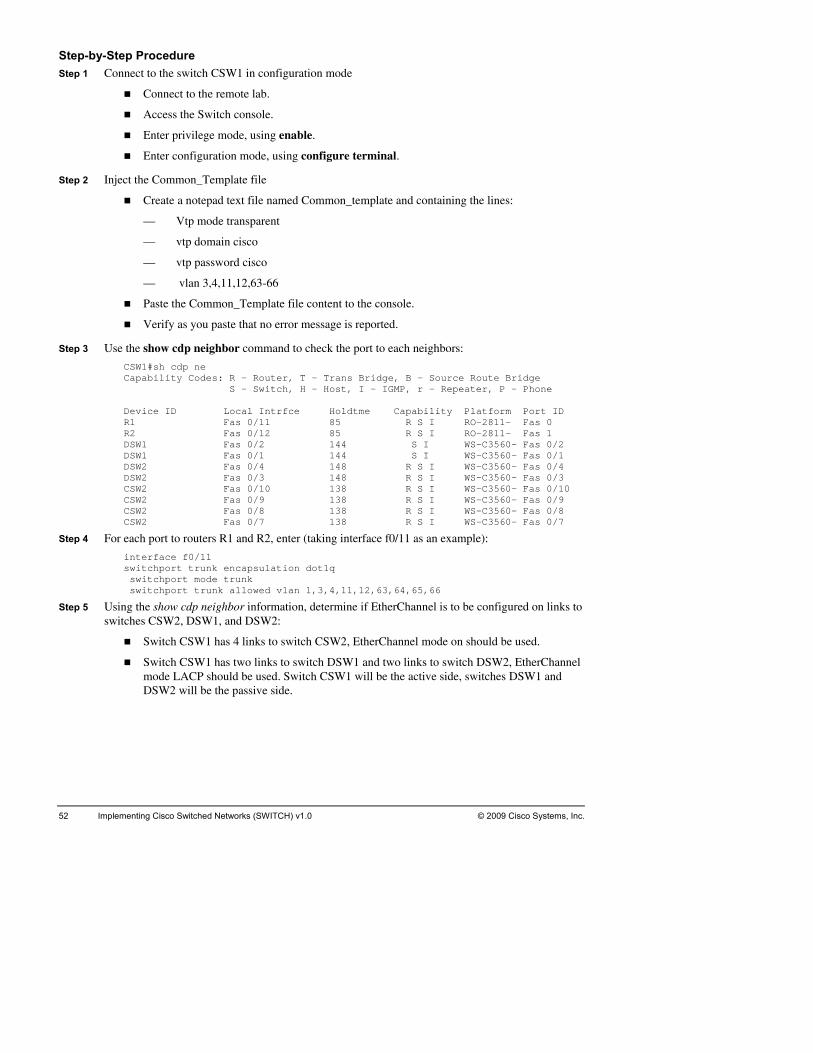
52 Implementing Cisco Switched Networks (SWITCH) v1.0 © 2009 Cisco Systems, Inc.
StSt e
.
Step 2 Inject
nes:
— l n 3,4,11,12,63-66
nt to the console.
e is reported.
Step 3 Us port to each neighbors:
idge P - Phone
Device ID Local Intrfce Holdtme Capability Platform Port ID
DSW1 144 S I WS-C3560- Fas 0/2 DSW1DSW2DSW2CSW2CSW2CSW2CSW2
Step 4 For each
inteswit swi swi
Step 5 Using theswitches
S
m d. Switch CSW1 will be the active side, switches DSW1 and D
ep-by-Step Procedure ep 1 Connect to the switch CSW1 in configuration mod
Connect to the remote lab.
Access the Switch console.
Enter privilege mode, using enable.
Enter configuration mode, using configure terminal
the Common_Template file
Create a notepad text file named Common_template and containing the li
— Vtp mode transparent
— vtp domain cisco
— vtp password cisco
v a
Paste the Common_Template file conte
Verify as you paste that no error messag
e the show cdp neighbor command to check the
CSW1#sh cdp ne Capability Codes: R - Router, T - Trans Bridge, B - Source Route Br S - Switch, H - Host, I - IGMP, r - Repeater,
R1 Fas 0/11 85 R S I RO-2811- Fas 0 R2 Fas 0/12 85 R S I RO-2811- Fas 1
Fas 0/2 Fas 0/1 144 S I WS-C3560- Fas 0/1 Fas 0/4 148 R S I WS-C3560- Fas 0/4 Fas 0/3 148 R S I WS-C3560- Fas 0/3
Fas 0/10 138 R S I WS-C3560- Fas 0/10 Fas 0/9 138 R S I WS-C3560- Fas 0/9 Fas 0/8 138 R S I WS-C3560- Fas 0/8 Fas 0/7 138 R S I WS-C3560- Fas 0/7
port to routers R1 and R2, enter (taking interface f0/11 as an example):
rface f0/11 chport trunk encapsulation dot1q tchport mode trunk tchport trunk allowed vlan 1,3,4,11,12,63,64,65,66
show cdp neighbor information, determine if EtherChannel is to be configured on links to CSW2, DSW1, and DSW2:
witch CSW1 has 4 links to switch CSW2, EtherChannel mode on should be used.
Switch CSW1 has two links to switch DSW1 and two links to switch DSW2, EtherChannel ode LACP should be useSW2 will be the passive side.

© 2009 Cisco Systems, Inc. Lab Guide 53
Step 6 Configure the link to switch CSW2, using the show cdp neighbor information and the EtherChannel table from the Information packet:
interface range f0/7 - 10 switc swit swit 66 chan exit inteswitc swit swit 66
Step 7 Configure formation and the EtherChan
66 chan exit inteswitc switswitc
Step 8 Configure r information and the EtherChan
interswitc swit
inte swit swit swit 66 shut
Step 9 Repeat ste ports to switch D
Step 10 Repeat ste
Step 11 Use the sh
DSW1#Capab
155 S I WS-C2960- Fas 0/1 ASW2 Fas 0/7 156 S I WS-C2960- Fas 0/2
130 R S I WS-C3560- Fas 0/5 128 R S I WS-C3560- Fas 0/4
- Fas 0/3 0- Fas 0/2
CSW1 163 R S I WS-C3560- Fas 0/1
hport trunk encapsulation dot1q chport mode trunk chport trunk allowed vlan 1,3,4,11,12,63,64,65,nel-group 33 mode on rface port-channel 33
unk encapsulation dot1q hport trchport mode trunk chport trunk allowed vlan 1,3,4,11,12,63,64,65,
the link to switch DSW1, using the show cdp neighbor innel table from the Information packet:
face range f0/1 - 2 interswitchport trunk encapsulation dot1q switchport mode trunk switchport trunk allowed vlan 1,3,4,11,12,63,64,65,
nel-group 31 mode active rface port-channel 31
q hport trunk encapsulation dot1chport mode trunk
64,65,66 hport trunk allowed vlan 1,3,4,11,12,63,
switch DSW2, using the show cdp neighbo the link tonel table from the Information packet:
face range f0/3 - 4 q hport trunk encapsulation dot1
chport mode trunk chport trunk allowed vlan 1,3,4,11,12,63,64,65,66 swit
channel-group 32 mode active shutdown exit
rface port-channel 32 chport trunk encapsulation dot1q chport mode trunk
4,11,12,63,64,65,chport trunk allowed vlan 1,3,down
ports to switch DSW1 and leaving theps 1 to 8 on switch CSW2, shutting down the SW2 enabled.
ps 1 and 2 on DSW1.
ow cdp neighbor information to discover neighbors:
sh cdp ne R - Router, T - Trans Bridge, B - Source Route Bridge ility Codes:
S - Switch, H - Host, I - IGMP, r - Repeater, P - Phone Device ID Local Intrfce Holdtme Capability Platform Port ID ASW1 Fas 0/6
DSW2 Fas 0/5 CSW2 Fas 0/4 CSW2 Fas 0/3 127 R S I WS-C3560CSW1 Fas 0/2 163 R S I WS-C356
Fas 0/1

54 Implementing orks (SWITCH) v1.0 © 2009 Cisco Systems, Inc. Cisco Switched Netw
Step 12 Using the show cdp neighbor information, determine if EtherChannel should be configured on links to switches CSW2, DSW1m and DSW2:
DSW1 has 1 link to ASW1 and ASW2, 1 link to DSW2. EtherChannel should not be used.
Step 13 Co
swi vlan 1,3,4,11,12,63,64,65,66 shu
Step 14 Configur EtherChannel table from
inte /1 - 2
,11,12,63,64,65,66 chan exi intswit swiswit
Step 15 Configur eighbor information and the EtherChannel table from
inteswit swi swi
inte swi swi swi ,66 shuDSW1Chan---- Grou----GrouPortPortProtMini Grou----GrouPort 8 Port rt-channels = 1 ProtMini
DSW1 has 2 links to CSW1 and 2 links to CSW2. EtherChannel mode LACP should be used. DSW1 will be the passive side for links to CSW1 and CSW2.
nfigure the link to switch DSW2, using the show cdp neighbor information:
interface f0/5 switchport trunk encapsulation dot1q switchport mode trunk
tchport trunk allowedtdown
e show cdp neighbor information and the e the link to switch CSW1, using th the Information packet:
rface range f0switchport trunk encapsulation dot1q switchport mode trunk switchport trunk allowed vlan 1,3,4
nel-group 31 mode passive t erface port-channel 31
t1q chport trunk encapsulation dotchport mode trunk chport trunk allowed vlan 1,3,4,11,12,63,64,65,66
e the link to switch CSW2, using the show cdp n the Information packet:
rface range f0/3 - 4 t1q chport trunk encapsulation do
tchport mode trunk tchport trunk allowed vlan 1,3,4,11,12,63,64,65,66
channel-group 32 mode passive shutdown exit
rface port-channel 32 tchport trunk encapsulation dot1qtchport mode trunk
3,4,11,12,63,64,65tchport trunk allowed vlan 1,tdown #sh etherchann nel-group listing:
---- --------------
p: 31 ------ p state = L3 s: 2 Maxports = 8 -channels: 1 Max Port-channels = 1 ocol: - mum Links: 0
p: 32 ------ state = L3 p
s: 2 Maxports =-channels: 1 Max Poocol: - mum Links: 0

© 2009 Cisco Systems, I Lab Guide 55 nc.
Step 16 Configure the link to switch ASW1, using the show cdp neighbor information:
interface f0/6 switc tion dot1q swit swit
Step 17 Configure
swit swit
Step 18 Configure
Inter
Step 19 Configure er:
Interswitc
12,63,64,65,66
Step 20 Repeat ste to 19 on DSW2, leaving links to switch CSW2 enabled and links to sw h DSW1, switch DSW2 is the passive sid
Step 21 On ASW1
VTP Version : running VTP1 (VTP2 capable)
Numbe : 17 VTP O : Transparent VTP D : cisco VTP P : Disabled VTP V : Disabled VTP TMD5 dConfi :00
Step 22 Repeat ste
Step 23 Use step 1
Step 24 Configure
InterSwitcSwitc
Step 25 Configure
Switchport mode access
SwitchpSwitc
Step 27 Repeat ste
hport trunk encapsulachport mode trunk
,11,63,65 chport trunk allowed vlan 1,3
the link to switch ASW2, using the show cdp neighbor information:
interface f0/7 switchport trunk encapsulation dot1q
chport mode trunk chport trunk allowed vlan 1,4,12,64,66
the link to the File server:
face f0/8 hport mode access Switc
Switchport access vlan 65
the link to the new rout
face f0/9 hport trunk encapsulation dot1q chport mode trunk swit
switchport trunk allowed vlan 1,3,4,11,
ps 1 and 2, then steps 11itch CSW1 shutdown. On the EtherChannel link to switce. File Server is in VLAN 66.
configurt the VTP mode.
Vtp domain cisco Vtp mode client Vtp password cisco Show vtp status
Configuration Revision : 0 Maximum VLANs supported locally : 1005
r of existing VLANs perating Mode
omain Name runing Mode
2 Mode raps Generation : Disabled
xBD 0x56 0x50 0xDE 0x3E igest : 0xDE 0x86 0x25 0guration last modified by 0.0.0.0 at 0-0-00 00:00
p 11 to discover neighbors.
6 model to configure links to DSW1 and DSW2.
the link to client CLT1:
face f0/3 hport mode access hport access vlan 3
the link to the FTP server:
Interface f0/4
Switchport access vlan 11
Step 26 Configure the link to the Web server:
Interface f0/5 ort mode access
hport access vlan 63
ps 1 and 2 on switch ASW2.

56 Implementing Cisco Switched Networks (SWITCH) v1.0 © 2009 Cisco Systems, Inc.
Step 28 Repeat step 11 to discover neighbors.
Step 29 Use step 16 model to configure links to switches DSW1 and DSW2.
Swit
Step 31 Configur
Inte
Step 32 Configur ver:
InteSwit
Step 30 Configure the link to client CLT2:
Interface f0/3 Switchport mode access
chport access vlan 4
e the link to the FTP server:
rface f0/4 Switchport mode access Switchport access vlan 12
e the link to the Web ser
rface f0/5 chport mode access
Switchport access vlan 64
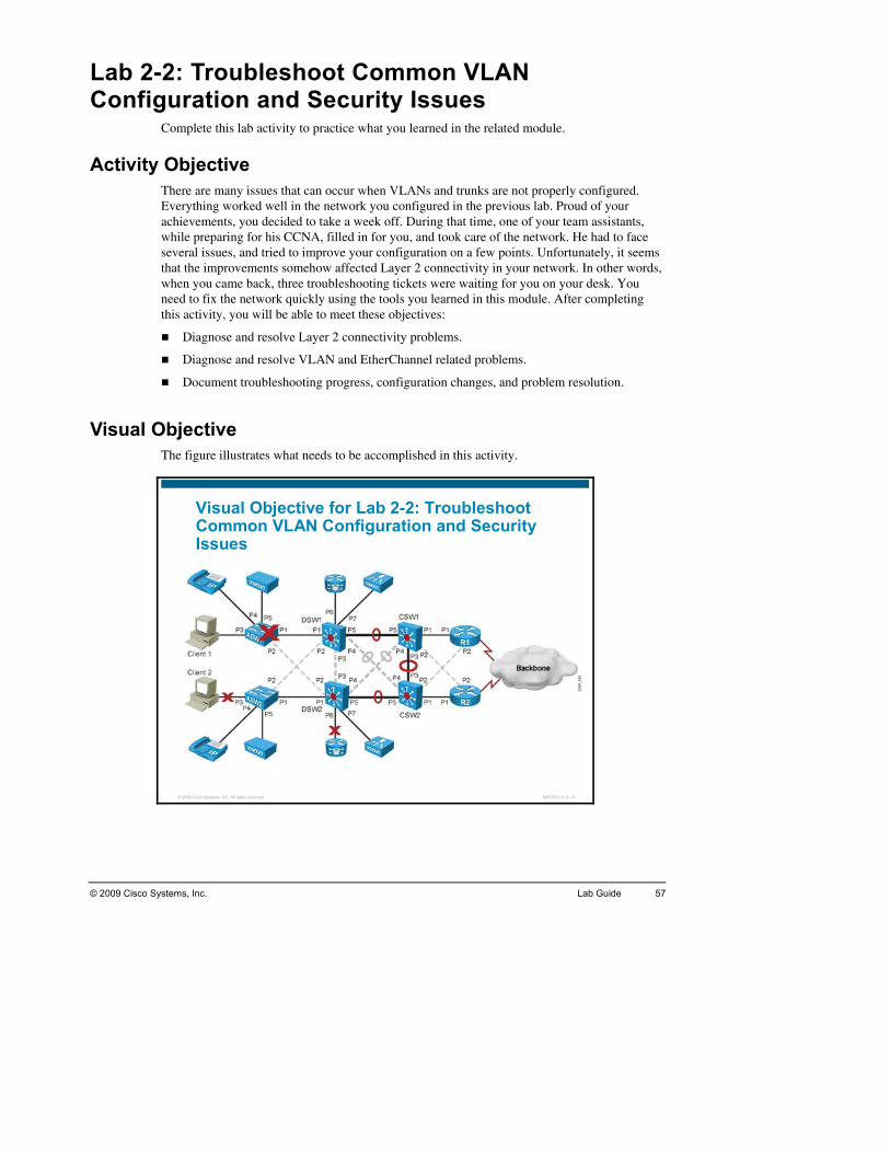
LaC
Activity Objn occur when VLANs and trunks are not properly configured. e network you configured in the previous lab. Proud of your
achievemenwhile severalthat thwhen need tthis ac
Di
Di
Do m resolution.
VisualT
b 2-2: Troubleshoot Common VLAN onfiguration and Security Issues
Complete this lab activity to practice what you learned in the related module.
ective There are many issues that caEverything worked well in th
ts, you decided to take a week off. During that time, one of your team assistants, preparing for his CCNA, filled in for you, and took care of the network. He had to face issues, and tried to improve your configuration on a few points. Unfortunately, it seems
e improvements somehow affected Layer 2 connectivity in your network. In other words, you came back, three troubleshooting tickets were waiting for you on your desk. You o fix the network quickly using the tools you learned in this module. After completing tivity, you will be able to meet these objectives:
agnose and resolve Layer 2 connectivity problems.
agnose and resolve VLAN and EtherChannel related problems.
cument troubleshooting progress, configuration changes, and proble
Objective he figure illustrates what needs to be accomplished in this activity.
© 2009 Cisco Systems, Inc. All rights reserved. SWITCH v1.0—5
ive for Lab 2-2: Troubleshoot N Configuration and Security
Visual ObjectCommon VLAIssues
© 2009 Cisco Systems, Inc. Lab Guide 57

58 Implementing C H) v1.0 isco Switched Networks (SWITC © 2009 Cisco Systems, Inc.
Ce commands that you will use in this activity.
Configuration Commands
ommand List The table describes th
Command Description
confi l Enters global c from privileged EXEC mode, gure termina onfiguration mode,
enabl password Enters the privileg de command interpreter e password ed EXEC mo
exit its the curreEx nt mode
intergigab
ach
face fastethernet | itethernet slot/port
Enters interfwith a Fast Et
e configuration mode for a Cisco Catalyst switch ernet or Gigabit Ethernet interface installed
inter nge fastegigabslot/endin
Selects a rangface rathernet | itethernet starting_port - g_port
e of interfaces to configure
name Specifies a naconfiguration mode
vlan-name me for a VLAN for either VLAN database or VLAN
no intype
les a VLAN interface terface vlan vlan-id Disab
ping Sends an ICMPdefault settings
ip-address echo to the designated IP address, using the of size and response window time
show interface interface-id sw
Displays the s the interface itchport
witch port configuration of
show ce trunk Displays the trunk configuration of the interface interfa
show Displays VLANvlan information
show vtp status Shows the VTP configuration
shutd orown/no shutdown Shuts down enables an interface
switcvlan-
Specifies the default VLAN, which is used if the interface stops ing
hport access vlan id trunk
switc the interface into permanent nontrunking mode and negotiates to c
hport mode access Puts onvert the link into a nontrunk link
switc Puts the interfa negotiates to convert the lin
hport mode trunk ce into permanent trunking mode andk into a trunk link
switc off DTPhport nonegotiate Turns negotiation
switcvlan
thehport trunk allowed remove vlan-list
Configures list of VLANs allowed on the trunk.
switcencap
Specifies 802.1Q encapsulation on the trunk link hport trunk sulation dot1q
switchport trunk encap
Specifies ISL esulation isl
ncapsulation on the trunk link
telne termin or switch that permits yo er the
t ip-address Starts a al emulation program from a PC, router,u to access network devices remotely ov
network

© 2009 Cisco Systems, Inc. Lab Guide 59
Command Description
interface interface-id channgroup-desira
Unconditionally enable PAgP. Desirable mode places an interface otiatin interfth anoten de
el-group channel-number mode ble
into a negwith otherformed wimode. Wh
g state in which the interface initiates negotiations aces by sending PAgP packets. A channel is
her port group in either the desirable or auto sirable is enabled, silent operation is the default.
show rinterface interface-id
Displays interfacunning-config e-specific configuration information.
vtp do P doon mod
main domain-name Sets the VTconfigurati
main name in either the VLAN database or e
vtp moserver
TP mde [ client | | transparent ]
Sets the V ode
Job Aids These jo plete the lab activity.
e Tickets
eshooting Log
b aids are available to help you com
Troubl
Troubl

60 Implementing Cisco Switched Networks (SWITCH) v1.0 © 2009 Cisco Systems, Inc.
T
conclLuckrepla
This n you come in and asked your assistant how things went, he tells you that he stayed late trying to get things to work but in the end did not manage it. He asks you to have a look he dohis coswitc
Userand h
Your task is to diagnose the issues and restore switch ASW1 as a fully functional access switch on th
Trouble Ticket B: VLAN 66 Access Problem Yourbacku stalled beyond the switch CSW2 and no devices in the network seem to be able to reach VLAN 66 anymore. The File2 Server team first thought of a hacker attack
be intact. ce to router
connefortu
Your66 coand R
Trouble TicYour assistan on this Monday morning. He complains that he already spent hours assistthat tabou
your assistant started figuration issue u exactly what
impro
Your
rouble Ticket A: Switch Replacement has Gone Wrong Late Friday afternoon, the access switch ASW1 failed and your assistant quickly had to
ude that the power supply had gone bad and that the switch needed to be replaced. ily, your team still had a similar switch on the shelf and your assistant rushed on site to ce it.
morning, whe
because he is out of ideas. When you ask him what the exact problem is, he tells you that es not know and that it “simply does not work”. He first thought was the issue came from nfiguration on switch ASW1, but then he also tried to verify and improve the other
hes on the path and is not sure anymore.
on PC Client 1 has already started to complain that he cannot get access to the network e needs this problem to be fixed today.
e network.
assistant also reports a call on Thursday evening from the File2 Server administrator. A p File2 server was in
and removed the File2 from the network for forensic analysis. The Server seems toThe File2 Server team then decided to try to ping from router R1 VLAN 66 interfaR2 VLAN 66 interface. The ping fails. They are convinced that your assistant broke
ctivity for this VLAN and ask you to fix the issue immediately. Each lost minute costs a ne.
task is to identify the misconfigured item and solve the issue to recover router R1 VLAN nnectivity to router R2 VLAN 66 connectivity. R1 VLAN 66 IP address is 10.1.66.251, 2 VLAN 66 IP address is 10.1.66.252.
ket C: Gateway Unreachable t seems depressed
trying to help PC Client 2 who could not reach his gateway, router R2, anymore. Your ant is convinced that PC Client 2 user broke his PC configuration, and does not believe he issue has anything to do with the fact that your assistant improved some minor points t the network configuration.
Although you trust your assistant, the fact that the issue started as soon as improving the configuration makes you wonder if there would not be a consomewhere on one switch. The fact that your assistant is reluctant to tell yo
vements were made when the failure occurred clearly contribute to your doubts.
task is to ensure that PC Client 2 can ping router R2.

© 2009 Cisco Systems, Inc. Lab Guide 61
Inm the troubleshooting tickets, this first troubleshooting lab contains three
types o
Tr s communication issues between switch ASW1 and router R1, thus in the upper part of the lab.
ropriate roles and coordinate device access between the team members. A logical the workload could be to assign the upper section of the pod (client CLT1the pothe uplab coboth thorganiteam mthe coshouldreloadmembthe neelater la
Once rissuesfacilitatroubl
The in directions to prepare the lab equipment for this lab. After the instructor indicates that the lab is fully prepared, you are ready to start troubleshooting.
structions As you can see fro
f issues:
ouble Ticket A involve
Trouble Ticket C involves communication issues between client CLT2 and router R2, thus in the lower part of the lab.
Trouble Ticket B involves communication issues between the upper and the lower part of the lab.
Together with your team members, create a troubleshooting plan to divide the work, assign each team member app
way of organizing-switch ASW1-switch DSW1-switch CSW1-router R1) to one team and the lower part of d (client CLT2, switches ASW2, DSW2, and CSW2) to a second team. Issues affecting per part of the lab could be solved by the first team. Issues affecting the lower part of the uld be solved by the second team. The whole team will have to work out issues affecting e upper and lower section. This is just an example of possible organization. Whichever zational model you choose, assign the primary responsibility for each of the devices to a ember. The team member who has primary responsibility for a device is in control of
nsole of that device and changes to the devices. This means that no other team member access the console, make changes to the device or execute disruptive actions such as ing or debugging without permission from the controlling team member. All team ers can access all devices via Telnet or SSH for non-disruptive diagnostic action, without d for permission of the controlling member. Responsibilities can be reassigned during bs if necessary.
oles have been assigned, work together on Trouble Tickets A, B, and C to resolve the . Document your progress in the “Troubleshooting Log” provided below in order to help te efficient communication within the team and to have an overview of your
eshooting process for reference during the lab debrief discussions.
structor will provide you with

62 Implementing Cisco Switched Networks (SWITCH) v1.0 © 2009 Cisco Systems, Inc.
Ts and results during the troubleshooting process.
roubleshooting Log Use this log to document your action
Trouble Ticket
Actions and results

© 2009 Cisco Systems, Inc. Lab Guide 63
Trouble Ticket
Actions and results

64 Implementing C sco Switched Ne orks (SWITCH) v1.0 © 2009 Cisco Systems, Inc. i tw
Trouble Ticket
Actions and results

© 2009 Cisco Systems, Inc. Lab Guide 65
Trouble Ticket
Actions and results

66 Implementing Cisco Switched Networks (SWITCH) v1.0 © 2009 Cisco Systems, Inc.
Aen you attain the results below.
Trouble Ticket A: are connected to switch ASW1 can acquire an IP address via DHCP.
You ave documented your process, your solution, and any changes that you have made to
Troub the router R1 interface in VLAN 66 to the router
R2 interface in VLAN 66.
VLAN 66 can be reached through all trunks.
r solution, and any changes that you have made to
Troub
ASW2 can ping the gateway router R2.
You have documented your process, your solution, and any changes that you have made to ons.
ctivity Verification You have completed this lab wh
Client PCs that
Client PCs that are connected to switch ASW1 can ping the gateway router R1.
hthe device configurations.
le Ticket B: You can complete an extended ping from
Switch CSW2
Switch CSW2 interfaces in VLAN 66 are properly configured.
You have documented your process, youthe device configurations.
le Ticket C: Client PCs that are connected to switch ASW2 can acquire an IP address via DHCP.
Client PCs that are connected to switch
the device configurati

Tr
resolv
ouble Ticket A: Sample Troubleshooting Flow The following pages illustrate an example of a method that you could follow to diagnose and
e Trouble Ticket A.
© 2009 Cisco Systems, Inc. All rights reserved. SWITCH v1.0—6
ASW1 management interface is in VLAN 1, CLT1 is in VLAN 3.
CLT2>ping 10.1.3.251
Pinging 10.1.3.251 with 32 bytes of data:
Request timed out.
Request timed out.
Request timed out.
Request timed out.
Ping statistics for 10.1.3.251:
Packets: Sent = 4, Received = 0, Lost = 4 (100% loss),
ASW1#ping 10.1.1.251
Sending 5, 100-byte ICMP Echos to 10.1.1.251, timeout is 2 seconds:
Packet sent with a source address of 10.1.1.1
!!!!!
Success rate is 100 percent (5/5)
Confirm or Deny Layer 3 Connectivity
Usualhave diaslead y
caused by a host-based firewall that is blocking pings).
Supat
Client Ping to terface fails.
ly, you would start troubleshooting the Layer 2 connectivity between devices because you scovered that there is no Layer 3 connectivity between two adjacent Layer 2 hosts, such
two hosts in the same VLAN or a host and its default gateway. Typical symptoms that could ou to start examining Layer 2 connectivity would be:
Failing pings between adjacent devices. (Keep in mind, though, that this may also be
ccessful pings between hosts in another Layer 2 domain but sharing the same physical h, such as hosts in another VLAN on the same link.
CLT1 is in VLAN 3 and obtains its IP address from router R1, acting as a DHCP server. router R1 interface in VLAN 3 from the client CLT1 command prompt in
Switch ASW1 is in VLAN1. Pings from switch ASW1 to router R1 interface in VLAN 1 succeed. This output shows that there is a physical path, Layer 2 and Layer 3 connectivity between switch ASW1 and router R1.
You can narrow the issue down to a physical connectivity issue between switch ASW1 and client CLT1, or a VLAN issue.
© 2009 Cisco Systems, Inc. Lab Guide 67

© 2009 Cisco Systems, Inc. All rights reserved. SWITCH v1.0—7
ASW1#sh vlan
VLAN Name Status Ports
---- --------------------------- --------- -------------------------------
1 default active Fa0/2, Fa0/4, Fa0/5 Fa0/6,
Fa0/7, Fa0/8, Fa0/9, Fa0/10
Fa0/12, Fa0/17, Fa0/18, Fa0/23
4 VLAN0004 active
11 VLAN0011 active Fa0/3
14 VLAN0014 active
63 VLAN0063 active
1002 fddi-default act/unsup
Key Clue: ASW1 VLAN Configuration
Once yowill
Verify Layer 1 and Layer 2 connectivity. If Layer 1 connectivity is broken, the interfaces should be down. If Layer 1 connectivity is established but Layer 2 connectivity is broken, a ua
D ion, baselines, and knowledge of your n you would expect frames to
pected path are actually up and forwarding traffic. If the actual
u have determined that the problem is most likely a Layer 2 or Layer 1 problem, you want to reduce the scope of the potential failures. You can diagnose Layer 2 problems with
this common troubleshooting method:
seful tool is cdp. Unless cdp is disabled, you should be able to use it to verify each device djacencies.
etermine the Layer 2 path. Based on documentatetwork in general, the next step is to determine the path that
follow between the affected hosts. Determining the expected traffic path beforehand will help you in two ways: It will give you a starting point for gathering information about what is actually happening on the network and it will make it easier to spot abnormal behavior. The second step in determining the Layer 2 path is to follow the expected path and verify that the links on the extraffic path is different from your expected path, this step may give you clues about the particular links or protocols that are failing and the cause of these failures.
In this case, layer 2 connectivity might be involved as the VLAN database on switch ASW1 does not show VLAN 3. If the VLAN does not exist, CLT1 cannot communicate with its gateway in VLAN 3. You can create VLAN 3 on switch ASW1 from the global configuration mode.
68 Implementing C ched Networks (SWITCH) v1.0 © 2009 Cisco Systems, Inc. isco Swit

© 2009 Cisco Systems, Inc. All rights reserved. SWITCH v1.0—8
CLT1 is supposed to be in VLAN 3
Show running-config interface f0/3
Building configuration...
Current configuration : 189 bytes
!
interface FastEthernet0/3
description to CLT1
switchport access vlan 11
switchport mode access
End
Config terminal
Int f0/3
Switchport access vlan 3
% Access VLAN does not exist. Creating vlan 3
Key Clue: ASW1 Port Configuration
AnotVLAN 11connectVLAN 11
You can change it to VLAN 3. If VLAN 3 has not been created before, the 2960 platform create
Tryingthe iss
her key piece of information comes from the previous page that displays information about . It is said to be active on interface f0/3, which is the interface to which client CLT1
s. Verifying the f0/3 interface configuration shows that it is set to access mode, but in .
s the VLAN automatically as soon as a port is affected to that VLAN.
to ping router R1 from client CLT 1 at this stage would still fail. You need to examine ue a little bit further.
© 2009 Cisco Systems, Inc. Lab Guide 69
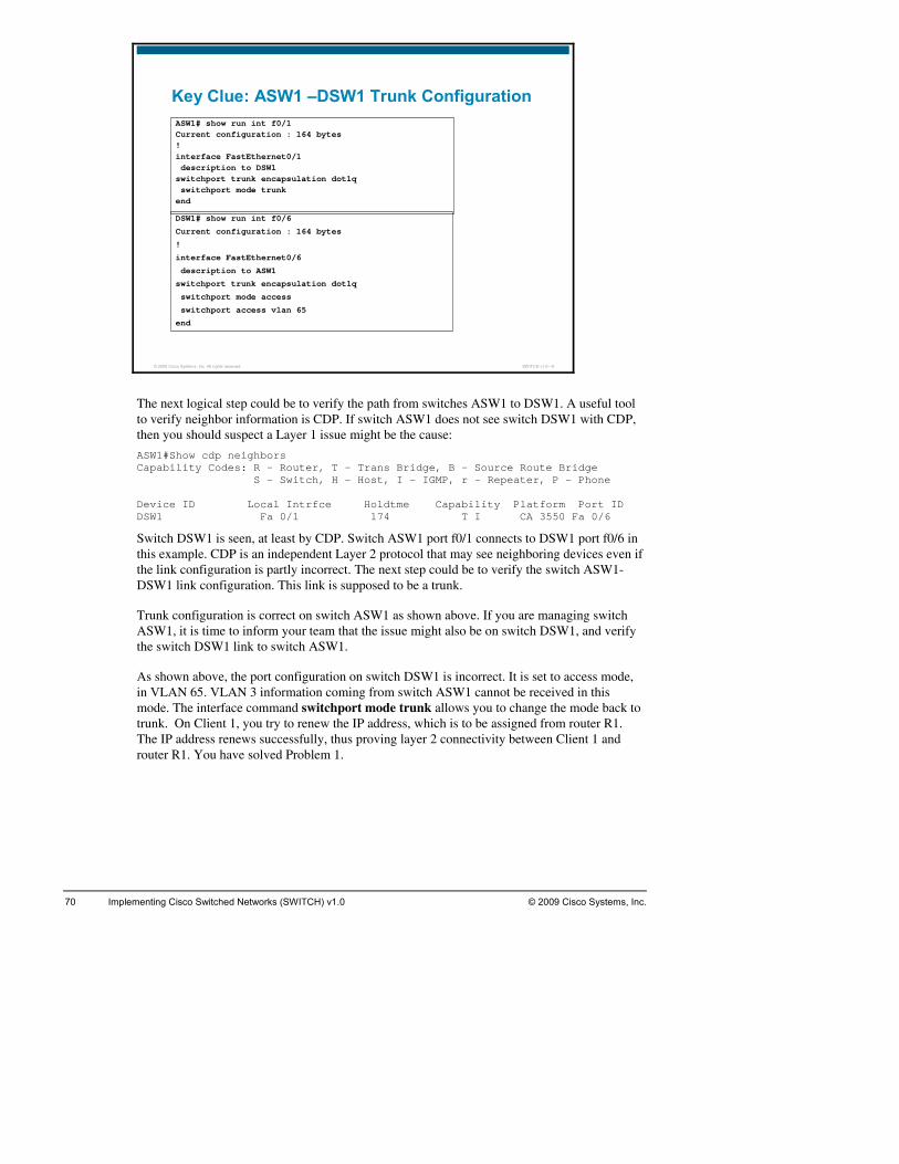
© 2009 Cisco Systems, Inc. All rights reserved. SWITCH v1.0—9
ASW1# show run int f0/1Current configuration : 164 bytes!interface FastEthernet0/1description to DSW1
switchport trunk encapsulation dot1qswitchport mode trunk
end
DSW1# show run int f0/6
Current configuration : 164 bytes
!
interface FastEthernet0/6
description to ASW1
switchport trunk encapsulation dot1q
switchport mode access
switchport access vlan 65
end
Key Clue: ASW1 –DSW1 Trunk Configuration
The
then yo
ASW1#Show cdp neighbors Capability Codes: R - Router, T - Trans Bridge, B - Source Route Bridge DeviDSW1
Switc port f0/6 in this e r 2 protocol that may see neighboring devices even if the liDSW
TrunASWthe sw
As shin VLmodetrunk outer R1. The IP address renews successfully, thus proving layer 2 connectivity between Client 1 and route
next logical step could be to verify the path from switches ASW1 to DSW1. A useful tool to verify neighbor information is CDP. If switch ASW1 does not see switch DSW1 with CDP,
u should suspect a Layer 1 issue might be the cause:
S - Switch, H - Host, I - IGMP, r - Repeater, P - Phone
ce ID Local Intrfce Holdtme Capability Platform Port ID Fa 0/1 174 T I CA 3550 Fa 0/6
h DSW1 is seen, at least by CDP. Switch ASW1 port f0/1 connects to DSW1xample. CDP is an independent Layenk configuration is partly incorrect. The next step could be to verify the switch ASW1-1 link configuration. This link is supposed to be a trunk.
k configuration is correct on switch ASW1 as shown above. If you are managing switch 1, it is time to inform your team that the issue might also be on switch DSW1, and verify itch DSW1 link to switch ASW1.
own above, the port configuration on switch DSW1 is incorrect. It is set to access mode, AN 65. VLAN 3 information coming from switch ASW1 cannot be received in this . The interface command switchport mode trunk allows you to change the mode back to . On Client 1, you try to renew the IP address, which is to be assigned from r
r R1. You have solved Problem 1.
70 Implementing Cisco Switched Networks (SWITCH) v1.0 © 2009 Cisco Systems, Inc.

© 2009 Cisco Systems, Inc. Lab Guide 71
Al
duringother p
_____ ________________________________________
______
__________
__________________________________________________________________________
__________
______
______
______
__________________________________________________________________________
__________________________________________________________________________
______
______
______
__________
__________________________________________________________________________
__________
______
______
______
__________________________________________________________________________
__________________________________________________________________________
______
______
______
__________
ternate Resources and Solutions to the One You Used Other groups may use a solution different from yours. Possible solutions will be discussed
the debrief period after the lab. For your reference, use the following space to document ossible solutions.
_____________________________
____________________________________________________________________
________________________________________________________________
________________________________________________________________
____________________________________________________________________
____________________________________________________________________
____________________________________________________________________
____________________________________________________________________
____________________________________________________________________
____________________________________________________________________
________________________________________________________________
________________________________________________________________
____________________________________________________________________
____________________________________________________________________
____________________________________________________________________
____________________________________________________________________
____________________________________________________________________
____________________________________________________________________
________________________________________________________________

72 Implementing Cisco Switched Networks (SWITCH) v1.0 © 2009 Cisco Systems, Inc.
_____
__________________________________________________________________________
_____
_____
_____
_____
__________________________________________________________________________
__________________________________________________________________________
_____
_____
_____
_____
__________________________________________________________________________
_____
_____
_____
_____
__________________________________________________________________________
__________________________________________________________________________
_____
_____
_____
_____
__________________________________________________________________________
_____
_____
_____
_____________________________________________________________________
_____________________________________________________________________
_____________________________________________________________________
_____________________________________________________________________
_____________________________________________________________________
_____________________________________________________________________
_____________________________________________________________________
_____________________________________________________________________
_____________________________________________________________________
_____________________________________________________________________
_____________________________________________________________________
_____________________________________________________________________
_____________________________________________________________________
_____________________________________________________________________
_____________________________________________________________________
_____________________________________________________________________
_____________________________________________________________________
_____________________________________________________________________
_____________________________________________________________________
_____________________________________________________________________

Tr
resolv
ouble Ticket B: Sample Troubleshooting Flow The following pages illustrate an example of a method that you could follow to diagnose and
e Trouble Ticket B.
© 2009 Cisco Systems, Inc. All rights reserved. SWITCH v1.0—10
R1#pingProtocol [ip]: Target IP address: 10.1.66.252Repeat count [5]: Datagram size [100]: Timeout in seconds [2]: Extended commands [n]: ySource address or interface: 10.1.66.251Type of service [0]: Set DF bit in IP header? [no]: Validate reply data? [no]: Data pattern [0xABCD]: Loose, Strict, Record, Timestamp, Verbose[none]: Sweep range of sizes [n]: Type escape sequence to abort.Sending 5, 100-byte ICMP Echos to 10.1.66.252, timeout is 2 seconds:Packet sent with a source address of 10.1.66.251 .....Success rate is 0 percent (0/5)
Connectivity Verification: R1 to R2 in VLAN 66
The firtroubleshprobleprobleor CS
st test can be to ping router R2 from router R1 interface in VLAN 66. As reported on the ooting ticket, the ping is unsuccessful. This issue could come from IP addressing
ms on routers R1 or R2 as well as layer 2 configuration problems. If you start this m as a layer 2 issue, you might begin by looking at the configurations on switch CSW1
W2.
© 2009 Cisco Systems, Inc. Lab Guide 73

© 2009 Cisco Systems, Inc. All rights reserved. SWITCH v1.0—11
interface FastEthernet0/7switchport trunk encapsulation dot1qswitchport mode trunkshutdownchannel-group 33 mode on!interface FastEthernet0/8switchport trunk encapsulation dot1qswitchport mode trunkshutdownchannel-group 33 mode on…/…
Key Clue: CSW2 Links to CSW1
A loCSW1
On s
Show run int f0/11 Buildi Curr! interface FastEthernet0/11 swi swiend DSW1Fast is up (connected) …/… The nected. The known on CSW1: CSW1 VLAN s ---- ---------------------------- …/… 66 …/…
VLA ed on switcThe c
gical step is to verify switch CSW1 to switch CSW2 link configuration, along with switch to router R1 and switch CSW2 to router R2 configurations
witch CSW1, the link to router R1 is supposed to be a trunk:
ng configuration...
ent configuration : 95 bytes
tchport trunk encapsulation dot1q tchport mode trunk
#sh int f0/11 Ethernet0/11 is up, line protocol
link to R1 is configured properly, and con step could be to verify if VLAN 66 isnext
#sh vlan
Name Status Port--- --------- --- -----------------------------
VLAN0066 active
N 66 is known, at least on switch CSW1. The same verifications could be conducth CSW2, verifying the trunk link to router R2 along with switch CSW2 VLAN database.
be valid, just like on switch CSW1. onfiguration should
74 Implementing witched Networks (SWITCH) v1.0 © 2009 Cisco Systems, Inc. Cisco S

© 2009 Cisco Systems, Inc. Lab Guide 75
In a step
CSW1#sh oup: Port- ----- Age o l = 0d:00h:45m:07s Logic 2/24 Number of ports = 0 HotStPort Proto
The Et nfirm this point b
Show inter swit swit channe mode passive ! inter swit swit chan! inter swit swit chan! inter swit swit chan
They a 2) is still in on mode, passive on swi decide to correct this:
CSW1#Enter h CNTL/Z. CSW1 CSW1 CSW1 CSW1
You thping w
by step approach, you could verify the link between switches CSW1 and CSW2:
ow etherchannel 33 port-ch Port-channels in the gr ---------------------------
channel: Po33 (Primary Aggregator)
-------
f the Port-channe slot/port = al
andBy port = null state = Port-channel Ag-Not-Inuse col = LACP
herChannel link is not in use! It shows LACP instead of “on”! You can coy checking the physical connections:
run face FastEthernet0/7 chport trunk encapsulation dot1q chport mode trunk l-group 33
face FastEthernet0/8 chport trunk encapsulation dot1q chport mode trunk nel-group 33 mode passive
FastEthernet0/9 facechport trunk encapsulation dot1q chport mode trunk nel-group 33 mode passive
face FastEthernet0/10 rt trunk encapsulation dot1q chpo
chport mode trunk nel-group 33 mode passive
other end (switch CSWre obviously in a wrong mode. Thetch CSW1 will not create an EtherChannel. You
conf t configuration commands, one per line. End wit(config)#int ran f0/7 - 10
gr 33 mo pas (config-if-range)#no channel-(config-if-range)#channel-gr 33 mo on (config-if-range)#end
en may want to try again to ping router R2 from router R1 interface in VLAN 66: the ould still be unsuccessful. There is more than one issue to solve for this ticket.

© 2009 Cisco Systems, Inc. All rights reserved. SWITCH v1.0—12
CSW2# show run int po 33
interface Port-channel33
switchport trunk encapsulation dot1q
switchport trunk allowed vlan 1-65,67-4094
switchport mode trunk…/…
Key Clue: CSW2 EtherChannel to CSW1
You may then shift your attention to switch CSW2 and verify its connection to switch CSW1. EtherChannel link does not seem to be operational on this side either. Verifying the ports iguration shows that they are in shutdown state. Once enabled, a verification of the Port-
el for these ports show that the link is up.
The confChann
CSW2#show etherchannel 33 port-channel Port---- Age LogiGC = null PortProt Port Inde EC state No of bits ---- 0 0 0 0 Time :00m:17s Fa0/9
Now reattempt a ping from router R1 to router R2. The ping is st r part to the issue to solve.
-channel: Po33 --------
of the Port-channel = 0d:00h:00m:49s cal slot/port = 2/24 Number of ports = 4 = 0x00000000 HotStandBy port state = Port-channel Ag-Inuse ocol = -
s in the Port-channel:
x Load Port --+------+------+------------------+----------- 00 Fa0/7 On 0 00 Fa0/8 On 0 00 Fa0/9 On 0 00 Fa0/10 On 0
since last port bundled: 0d:00h
that the ports are enabled, you may want toill unsuccessful. There is still anothe
76 Implementing Cisco Switched Networks (SWITCH) v1.0 © 2009 Cisco Systems, Inc.

© 2009 Cisco Systems, Inc. Lab Guide 77
While EtherCfrom t
CSW2#Enter ommands, one per line. End with CNTL/Z. L3SW4L3SW4L3SW4R1#piProtoTargeRepeaDatagTimeoExtenSourc .66.251 Type Set DValidData LooseSweepType Sendi timeout is 2 seconds: Packe .66.251 !!!!!Succe
verifying switch CSW2 configuration, you may see that VLAN 66 is not allowed on the hannel! You might have seen this issue at an earlier stage. It is shown here to isolate it
he shutdown issue. It is easy to correct:
conf t configuration c(config)#int po 33 (config-if)#sw trun all vla ad 66 (config-if)#end ng col [ip]: t IP address: 10.1.66.252
: t count [5]ram size [100]: ut in seconds [2]: ded commands [n]: y e address or interface: 10.1of service [0]: F bit in IP header? [no]: ate reply data? [no]: pattern [0xABCD]:
Verbose[none]: , Strict, Record, Timestamp, range of sizes [n]: escape sequence to abort.
6.252, ng 5, 100-byte ICMP Echos to 10.1.6f 10.1t sent with a source address o
ss rate is 100 percent (5/5)

78 Implementing Cisco Switched Networks (SWITCH) v1.0 © 2009 Cisco Systems, Inc.
A
durinother
____ _________________________________________
_____
_____
__________________________________________________________________________
_____
_____
_____
_____
__________________________________________________________________________
__________________________________________________________________________
_____
_____
_____
_____
__________________________________________________________________________
_____
_____
_____
_____
__________________________________________________________________________
__________________________________________________________________________
_____
_____
_____
_____
lternate Resources and Solutions to the One You Used Other groups may use a solution different from yours. Possible solutions will be discussed
g the debrief period after the lab. For your reference, use the following space to document possible solutions.
_____________________________
_____________________________________________________________________
_____________________________________________________________________
_____________________________________________________________________
_____________________________________________________________________
_____________________________________________________________________
_____________________________________________________________________
_____________________________________________________________________
_____________________________________________________________________
_____________________________________________________________________
_____________________________________________________________________
_____________________________________________________________________
_____________________________________________________________________
_____________________________________________________________________
_____________________________________________________________________
_____________________________________________________________________
_____________________________________________________________________
_____________________________________________________________________
_____________________________________________________________________

© 2009 Cisco Systems, Inc. Lab Guide 79
__________
__________________________________________________________________________
__________
______
______
______
__________________________________________________________________________
__________________________________________________________________________
______
______
______
__________
__________________________________________________________________________
__________
______
______
______
__________________________________________________________________________
__________________________________________________________________________
______
______
______
__________
__________________________________________________________________________
__________
______
______
______
________________________________________________________________
________________________________________________________________
____________________________________________________________________
____________________________________________________________________
____________________________________________________________________
____________________________________________________________________
____________________________________________________________________
____________________________________________________________________
________________________________________________________________
________________________________________________________________
____________________________________________________________________
____________________________________________________________________
____________________________________________________________________
____________________________________________________________________
____________________________________________________________________
____________________________________________________________________
________________________________________________________________
________________________________________________________________
____________________________________________________________________
____________________________________________________________________
____________________________________________________________________

Td
resol
rouble Ticket C: Sample Troubleshooting Flow The following pages illustrate an example of a method that you could follow to diagnose an
ve Trouble Ticket C.
© 2009 Cisco Systems, Inc. All rights reserved. SWITCH v1.0—13
ASW2#sh run int f0/3Building configuration...Current configuration : 82 bytes!interface FastEthernet0/3switchport access vlan 4switchport mode trunkend
ASW2#sh run int f0/1
Building configuration...
Current configuration : 82 bytes
!
interface FastEthernet0/1
switchport access vlan 4
switchport mode access
end
Key Clue: ASW2 Ports Configuration
A possiexamYou ob
ASW2EnteASW2(config)#int f0/3 ASW2(config-if)#sw mo ac ASW2
Sinceconfi port is f0/1. You notice this time that the port i unk mode:
ASW2EnteASW2ASW2ASW2
After yorenew
ble first step is to verify switch ASW2 port to client CLT2 configuration. In this ple, the port is f0/3. The port is in trunk mode. It should be in access mode in VLAN 4.
viously correct this mistake:
#conf t r configuration commands, one per line. End with CNTL/Z.
(config-if)#end
the switch ASW2 port configuration was incorrect, you may also want to verify the port guration to switch DSW2. In this example, thes in access mode, so you need to change it to tr
#conf t r configuration commands, one per line. End with CNTL/Z. (config)#int f0/1 (config-if)#sw mo trunk (config-if)#end
u have made the changes, have you resolved the issue? Test the solution by trying to client CLT2 IP address and if it fails, then there are other issues.
80 Implementing nc. Cisco Switched Networks (SWITCH) v1.0 © 2009 Cisco Systems, I

© 2009 Cisco Systems, Inc. All rights reserved. SWITCH v1.0—14
DSW2#sh run int f0/6Building configuration...Current configuration : 104 bytes!interface FastEthernet0/6switchport trunk encapsulation dot1qswitchport mode trunkshutdownend
Key Clue: DSW2 Link to ASW2
Now turn your attention to switch DSW2 and check its connection to switch ASW2. The port is own so you need to re-enable it for communication to switch ASW2:
conf t configuration commands, one per line. End with CNTL/Z.
shutd
DSW2#EnterDSW2(config)#int f0/6 DSW2(config-if)#no sh DSW2(
When rnotice wrong VLAN. Client CLT2 has an address in VLAN 1 instead
config-if)#end
enewing the client CLT2 IP address this time, CLT2 does obtain an IP address but you that the IP address is on the of VLAN 4.
© 2009 Cisco Systems, Inc. Lab Guide 81

© 2009 Cisco Systems, Inc. All rights reserved. SWITCH v1.0—15
DSW2#sh run int po 32Building configuration...Current configuration : 125 bytes!interface Port-channel32switchport trunk encapsulation dot1qswitchport trunk native vlan 4switchport mode trunkend
Key Clue: Native VLAN
You have already checked the port configuration for client CLT2 on switch ASW2 and you it is an Access port in VLAN 4. The switches DSW1 and DSW2 port configuration show
the ports are in trunking mode and a possible cause might be a native VLAN problem. ing the port configuration on switch DSW2 to switches CSW1 and CSW2 verifies the
know thatCheckproblem as a Native VLAN issue:
DSW2Buil Curr! inte swi swi swiend DSW2Buil Curr! inte swi swi swiend
Both l the other links are in native VLAN 1, the DHCP reque DSW2 to switch CSW2 on VLAN 4, and switch CSW ter R2.
Chan CSW1 and between switches DSW2 and C
#sh run int po 32 ding configuration...
ent configuration : 125 bytes
rface Port-channel32 tchport trunk encapsulation dot1q tchport trunk native vlan 4 tchport mode trunk
#sh run int po 31 ng configuration... di
ent configuration : 125 bytes
rface Port-channel31 tchport trunk encapsulation dot1q tchport trunk native vlan 4 tchport mode trunk
links are in native VLAN 4. As alst is forwarded untagged to from switch
forwards it to its native VLAN 1 to rou2
ging the native VLAN between switches DSW2 andSW2 solves the problem.
82 Implementing Cisco Switched Networks (SWITCH) v1.0 © 2009 Cisco Systems, Inc.

© 2009 Cisco Systems, Inc. Lab Guide 83
Al
duringother p
_____ ________________________________________
______
__________
__________________________________________________________________________
__________
______
______
______
__________________________________________________________________________
__________________________________________________________________________
______
______
______
__________
__________________________________________________________________________
__________
______
______
______
__________________________________________________________________________
__________________________________________________________________________
______
______
______
__________
ternate Resources and Solutions to the One You Used Other groups may use a solution different from yours. Possible solutions will be discussed
the debrief period after the lab. For your reference, use the following space to document ossible solutions.
_____________________________
____________________________________________________________________
________________________________________________________________
________________________________________________________________
____________________________________________________________________
____________________________________________________________________
____________________________________________________________________
____________________________________________________________________
____________________________________________________________________
____________________________________________________________________
________________________________________________________________
________________________________________________________________
____________________________________________________________________
____________________________________________________________________
____________________________________________________________________
____________________________________________________________________
____________________________________________________________________
____________________________________________________________________
________________________________________________________________

84 Implementing Cisco Switched Networks (SWITCH) v1.0 © 2009 Cisco Systems, Inc.
_____
__________________________________________________________________________
_____
_____
_____
_____
__________________________________________________________________________
__________________________________________________________________________
_____
_____
_____
_____
__________________________________________________________________________
_____
_____
_____
_____
__________________________________________________________________________
__________________________________________________________________________
_____
_____
_____
_____
__________________________________________________________________________
_____
_____
_____
_____
_____________________________________________________________________
_____________________________________________________________________
_____________________________________________________________________
_____________________________________________________________________
_____________________________________________________________________
_____________________________________________________________________
_____________________________________________________________________
_____________________________________________________________________
_____________________________________________________________________
_____________________________________________________________________
_____________________________________________________________________
_____________________________________________________________________
_____________________________________________________________________
_____________________________________________________________________
_____________________________________________________________________
_____________________________________________________________________
_____________________________________________________________________
_____________________________________________________________________
_____________________________________________________________________
_____________________________________________________________________
_____________________________________________________________________

© 2009 Cisco Systems, Inc. Lab Guide 85
La_____________
__________
______
______
______
__________________________________________________________________________
__________________________________________________________________________
______
______
______
__________
__________________________________________________________________________
__________
______
______
______
__________________________________________________________________________
__________________________________________________________________________
______
______
______
__________
__________________________________________________________________________
__________
______
______
______
b 2-2: Key Commands and Tools Used _____________________________________________________________
________________________________________________________________
____________________________________________________________________
____________________________________________________________________
____________________________________________________________________
____________________________________________________________________
____________________________________________________________________
____________________________________________________________________
________________________________________________________________
________________________________________________________________
____________________________________________________________________
____________________________________________________________________
____________________________________________________________________
____________________________________________________________________
____________________________________________________________________
____________________________________________________________________
________________________________________________________________
________________________________________________________________
____________________________________________________________________
____________________________________________________________________
____________________________________________________________________

86 Implementing Cisco Switched Networks (SWITCH) v1.0 © 2009 Cisco Systems, Inc.
L
Activity Objective nteresting part of module 2, you would like to experiment on this ers, each of them having a link to both switches CSW1 and CSW2,
and ywantmovithe swwill b
P
C
Impl
Inforo accomplish in this activity. Read it carefully.
ents common to all devices in the network, along with information specific to each device.
ImMakeyour lab 3 witches you use for this task before
501 and 51, and switch CSW1. Start by configuring switch CSW1 to Connect to routers R1 and R2, and create an interface for VLAN
51. C
ab 2-3: Implement Private VLANs Complete this lab activity to practice what you learned in the related module.
As private VLANs were an ifeature. The lab has two rout
ou think that it would be interesting to use them to try the isolated VLAN. As you do not to keep your routers isolated for the next labs, this feature will have to be removed when ng to lab 3-1. So make sure that you saved before this optional task, and that you reboot
itches you use for this task before moving to next lab. After completing this activity, you e able to meet these objectives:
lan a segmented private VLANs implementation.
reate a private VLANs implementation and verification plan.
ement private VLANs.
mation Packet This packet contains the information needed tThe Information Packet describes the requirem
plementation Policy sure you saved your configuration before moving to this step. As you do not want to keep routers isolated for the next labs, private VLANs will have to be removed when moving to -1. Be sure to save before this optional task, and reboot the s
moving to next lab.
For this task, use VLANs support VLAN 501 and 51.
onfigure a static IP address for each router using the table below:
Device name Interface IP address VLAN
R1 10.1.51.1/24 51 F0/0.51
R2 F0/1 10.1.51.2/24 51
VerifCSW
Verify that both routers can ping each other from their VLAN 51 interface.
Once this poi , conv to isolated, using V e primary VLAN. ur configuration ful, routers R1 and e able to ping each other anymore.
You may want to use the Hint section of the lab to verify which steps are involved in this conficonfi 1 and R2 without saving the configu
y that switch CSW1 link to router R2 is enabled, and in VLAN 51. Verify that switch 1 trunk to router R1 allows VLAN 51.
nt is verified ert VLAN 51 LAN 501 as th If yo is success R2 should not b
guration. The end of the lab guide contains the solution for this task. Once your guration is working, reboot switch CSW1 and routers R
ration.

Network Diagram
© 2009 Cisco Systems, Inc. All rights reserved. SWITCH v1.0—16
Visual Objective for Lab 2-3: Configure Private VLANs
© 2009 Cisco Systems, Inc. Lab Guide 87
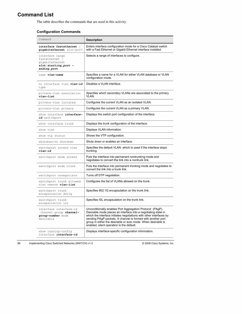
88 Implementing C H) v1.0 isco Switched Networks (SWITC © 2009 Cisco Systems, Inc.
Ce commands that are used in this activity.
Configuration Commands
ommand List The table describes th
Command Description
inter ernet | gigab slot/port
Enters interfac ode for a Cisco Catalyst switch with a Fast Eth interface installed.
face fastethitethernet
e configuration mernet or Gigabit Ethernet
interfastegigabslot/endin
ngface range thernet | itethernet
Selects a ra
starting_port - g_port
e of interfaces to configure.
name Specifies a name for a VLAN for either VLAN database or VLAN uration mode.
vlan-name config
no in n-id type
Disables a VLAN interface. terface vlan vla
priva vlan-list
Specifies whicVLAN.
te-vlan association h secondary VLANs are associated to the primary
priva e . te-vlan isolated Configures th current VLAN as an isolated VLAN
priva primary Configures the current VLAN as a primary VLAN. te-vlan
show id sw
sinterface interface-itchport
Displays the witch port configuration of the interface.
show s the trinterface trunk Display unk configuration of the interface.
show s VLANvlan Display information.
show s the VTP cvtp status Show onfiguration.
shutd orown/no shutdown Shuts down enables an interface.
switcvlan-
Specifies the default VLAN, which is used if the interface stops ing.
hport access vlanid trunk
switc cess Puts the interfa e and negotiates to c
hport mode ac ce into permanent nontrunking modonvert the link into a nontrunk link.
switc Puts the interfa negotiates to convert the link
hport mode trunk ce into permanent trunking mode and into a trunk link.
switc off DTPhport nonegotiate Turns negotiation.
switcvlan
thehport trunk allowed remove vlan-list
Configures list of VLANs allowed on the trunk.
switcencap
802.hport trunk sulation dot1q
Specifies 1Q encapsulation on the trunk link.
switcencap
Specifies ISL encapsulation on the trunk link. hport trunk sulation isl
interface interface-id changroupdesir
Unconditionall gP). mod ating state in
inter er interfaces by gP
nt
nel-group channel--number mode
Desirable which the
able sending PAgroup in either enabled, sile
y enables Port Aggregation Protocol (PAe places an interface into a negotiface initiates negotiations with othpackets. A channel is formed with another port the desirable or auto mode. When desirable is operation is the default.
show inter
Displays interfrunning-config face interface-id
ace-specific configuration information.

© 2009 Cisco Systems, Inc. Lab Guide 89
Johe job aids for this lab activity:
b Aids These are t
Value Location
Blank im ation requirements list Task 1 plement
Blank im plementation plan form Task 2
Blank verific Task 3 ation plan form
Debrief altern End of this lab ate solutions form
Implem Hint Section entation requirement hints
Implem Hint Section entation hints
Verifica int Section tion hints H
Solution c Configuration sectio b guide onfiguration answer key n at the end of the la

90 Implementing Cisco Switched Networks (SWITCH) v1.0 © 2009 Cisco Systems, Inc.
T
confifollowInforimpleeach
ask 1: Establish an Implementation Requirements List The first step in your configuration deployment is to create a list of the items needed to
gure each device (for example, for example devices involved, role, etc.). Use the ing table, the initial lab visual objective, the Implementation Policy and Devices
mation to create an Implementation Requirement list. Include the high-level mentation tasks needed for each device and how to obtain the information required for task. If you are unsure, use the hints information provided at the end of this lab.
Device High Level Task Information Source

© 2009 Cisco Systems, In Lab Guide 91 c.
Ta
configimporthe codetermmove tPackeinform
sk 2: Create an Implementation and Verification Plan The second step in your configuration deployment is to create a task list of each item to
ure on each device and in what order. The Implementation and Verification Plan is very tant, because it enables you to ensure that all requirements are properly configured and in rrect order. The task will help you setup configuration checkpoints. Use the plan to ine how you will verify that each required item was effectively configured. You will o the actual implementation in the next task. Use the following table and the Information
t to create the Implementation and Verification Plan. If you are unsure, use the hints ation provided at the end of this lab.
Complete √
Device ImplementationOrder
Values and items to implement
Verification method and expected results

92 Implementing C sco Switched Ne orks (SWITC ) v1.0 © 2009 Cisco Sy ems, Inc. i tw H st
Complete √
Device Implementation Order
Values and items to implement
Verification method and expected results

© 2009 Cisco Systems, Inc. Lab Guide 93
Talanned the implementation, you are ready
to consolutiospecificonfigconfigconfigensureabout
sk 3: Implement and Verify Now that you have all of the requirements and have p
nect to the remote lab and implement your solution. Do not forget to save! Once your n is implemented, verify your configuration is working and fulfills the requirements ed by the company. Keep in mind that once you leave the company, they will use your uration as a whitepaper to implement their network. The company will apply your uration, without modification, to connect any device of the same type as the one you ured for each port. Use the previous table to document the verifications you conducted to that your solution is complete. Hints are available at the end of this lab if you are unsure the verification steps.

94 Implementing Cisco Switched Networks (SWITCH) v1.0 © 2009 Cisco Systems, Inc.
Sce to document the details that you think are important to remember.
___
_____
_____
_____
__________________________________________________________________________
_____
_____
_____
_____
__________________________________________________________________________
__________________________________________________________________________
_____
_____
_____
_____
__________________________________________________________________________
_____
_____
_____
_____
__________________________________________________________________________
__________________________________________________________________________
_____
_____
_____
_____
tudent Notes Use the following spa
_______________________________________________________________________
_____________________________________________________________________
_____________________________________________________________________
_____________________________________________________________________
_____________________________________________________________________
_____________________________________________________________________
_____________________________________________________________________
_____________________________________________________________________
_____________________________________________________________________
_____________________________________________________________________
_____________________________________________________________________
_____________________________________________________________________
_____________________________________________________________________
_____________________________________________________________________
_____________________________________________________________________
_____________________________________________________________________
_____________________________________________________________________
_____________________________________________________________________
_____________________________________________________________________
_____________________________________________________________________

© 2009 Cisco Systems, Inc. Lab Guide 95
__________
__________________________________________________________________________
__________
______
______
______
__________________________________________________________________________
__________________________________________________________________________
______
______
______
__________
__________________________________________________________________________
__________
______
______
______
__________________________________________________________________________
__________________________________________________________________________
______
______
______
__________
__________________________________________________________________________
__________
______
________________________________________________________________
________________________________________________________________
____________________________________________________________________
____________________________________________________________________
____________________________________________________________________
____________________________________________________________________
____________________________________________________________________
____________________________________________________________________
________________________________________________________________
________________________________________________________________
____________________________________________________________________
____________________________________________________________________
____________________________________________________________________
____________________________________________________________________
____________________________________________________________________
____________________________________________________________________
________________________________________________________________
________________________________________________________________
____________________________________________________________________

96 Implementing Cisco Switched Networks (SWITCH) v1.0 © 2009 Cisco Systems, Inc.
A
durinother
____ _________________________________________
_____
_____
__________________________________________________________________________
__________________________________________________________________________
_____
_____
_____
_____
__________________________________________________________________________
_____
_____
_____
_____
__________________________________________________________________________
__________________________________________________________________________
_____
_____
_____
_____
__________________________________________________________________________
_____
_____
_____
_____
lternate Resources and Solutions to the One You Used Other groups may use a solution different from yours. Possible solutions will be discussed
g the debrief period after the lab. For your reference, use the following space to document possible solutions.
_____________________________
_____________________________________________________________________
_____________________________________________________________________
_____________________________________________________________________
_____________________________________________________________________
_____________________________________________________________________
_____________________________________________________________________
_____________________________________________________________________
_____________________________________________________________________
_____________________________________________________________________
_____________________________________________________________________
_____________________________________________________________________
_____________________________________________________________________
_____________________________________________________________________
_____________________________________________________________________
_____________________________________________________________________
_____________________________________________________________________
_____________________________________________________________________
_____________________________________________________________________

© 2009 Cisco Systems, Inc. Lab Guide 97
__________
__________________________________________________________________________
__________
______
______
______
__________________________________________________________________________
__________________________________________________________________________
______
______
______
__________
__________________________________________________________________________
__________
______
______
______
__________________________________________________________________________
__________________________________________________________________________
______
______
______
__________
__________________________________________________________________________
__________
________________________________________________________________
________________________________________________________________
____________________________________________________________________
____________________________________________________________________
____________________________________________________________________
____________________________________________________________________
____________________________________________________________________
____________________________________________________________________
________________________________________________________________
________________________________________________________________
____________________________________________________________________
____________________________________________________________________
____________________________________________________________________
____________________________________________________________________
____________________________________________________________________
____________________________________________________________________
________________________________________________________________
________________________________________________________________

98 Implementing Cisco Switched Networks (SWITCH) v1.0 © 2009 Cisco Systems, Inc.
L______________
_____
_____
_____
_____
__________________________________________________________________________
_____
_____
_____
_____
__________________________________________________________________________
__________________________________________________________________________
_____
_____
_____
_____
__________________________________________________________________________
_____
_____
_____
_____
__________________________________________________________________________
__________________________________________________________________________
_____
_____
_____
_____
ab 2-3: Key Commands and Tools Used ____________________________________________________________
_____________________________________________________________________
_____________________________________________________________________
_____________________________________________________________________
_____________________________________________________________________
_____________________________________________________________________
_____________________________________________________________________
_____________________________________________________________________
_____________________________________________________________________
_____________________________________________________________________
_____________________________________________________________________
_____________________________________________________________________
_____________________________________________________________________
_____________________________________________________________________
_____________________________________________________________________
_____________________________________________________________________
_____________________________________________________________________
_____________________________________________________________________
_____________________________________________________________________
_____________________________________________________________________
_____________________________________________________________________

© 2009 Cisco Systems, I idnc. Lab Gu e 99
Hiu are encouraged to complete the labs using your knowledge. If you need a tip, this section
contai
Lab 2-3 Hint Sheet: Imple
Imork, the first task asks you to create an
list details the elements needed to develop an implem
nts Yo
ns a series of hints to help you complete the lab.
ment private VLANs
plementation Requirements To facilitate the configuration of your netwImplementation Requirements list. The
entation plan. The following is an example of such a list:
Device Implementation Requirement Hint
CSW1 Create VLAN 51 and 501 Implementation Policy
L Implementation PolicAllows V ANs 51 and 501 on trunks to R1 y
Set link to R2 to VLAN 51 Implementation Policy
N d Implementation PolicSet VLA 501 as primary and 51 as isolate y
R1 Configure ation Policsubinterface to CSW1 in VLAN 51 Implement y
R2 Configure Implementation Polic interface to CSW1 in VLAN 51 y
Implementation and VerificIn task 2, you will ssible cAn exam of the I
ation Plan create an implementation plan. There are several po
mplementation and Verification Plan follows. orrect solutions.
ple
Complete √
Device Imple-menta-tion Order
Values and items to implement Verification method and expected results
Step-by-step No
1 CSW1 1 Create VLAN 51. Show vlan.
2 Create VLAN 501. Show vlan. 1
A 51R
o R1.
3 llow VLAN1.
on the trunk link to Show run interface t 2
4 C re link to R2 as access mode, VLAN 51.
Show run interface to R2.
3 onfigu
After R1 and Rc gured suc51 to be isolated.
w private vlan. 8 2 links are cessfully, set VLAN
Shoonfi
7
9 Set VLAN 501 to be primarmapped to VLA
w private vlan. y, ShoN 51.
7
R1 5 Configure subi e on link to R1 to be 10.1.51.1/24.
Show ip interface brief.nterfac 4
R2 C igure link t10.1.51.2/24.
brief.6 onf o CSW1 to be Show ip interface 5
P R1 interfa d succeed. 7 ing ce 10.1.51.1. Ping shoul 6
10 Try to ping R1 8 interface 10.1.51.1. Ping should fail.
CSW1, R1, R2
11 R without seload aving. Show run. 9
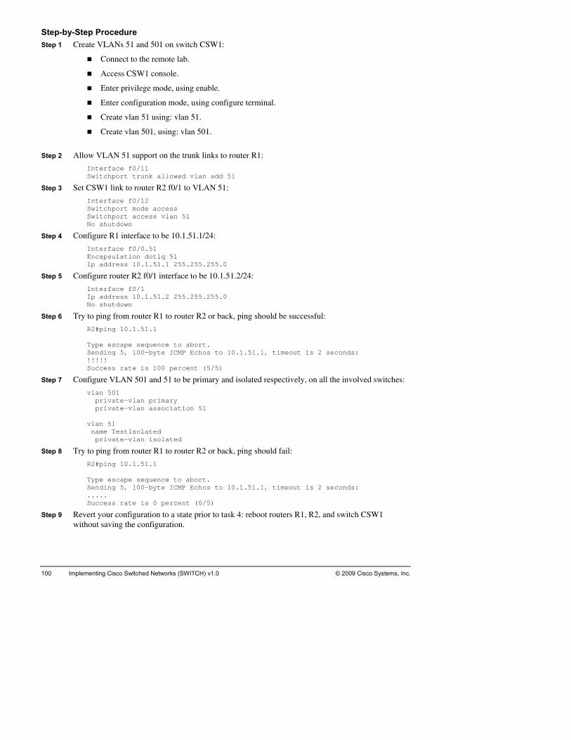
100 Implementing H) v1.0 © 2009 Cisco Systems, Inc. Cisco Switched Networks (SWITC
StSt switch CSW1:
.
Create vlan 51 using: vlan 51.
Step 2
Interface f0/11 Switchport trunk allowed vlan add 51
InteSwitSwit
InteEncaIp a
Step 5 Configur rface to be 10.1.51.2/24:
Ip ad .255.0 No s
Step 6 Try to pin successful:
Send Echos to 10.1.51.1, timeout is 2 seconds: !!!!Succ
pr pr 51 vlan nam pr
Step 8 Try to pin ail:
Type ce to abort. Send 0.1.51.1, timeout is 2 seconds: ....Succ
Step 9 Revert your configuration to a state prior to task 4: reboot routers R1, R2, and switch CSW1 without s
ep-by-Step Procedure ep 1 Create VLANs 51 and 501 on
Connect to the remote lab.
Access CSW1 console.
Enter privilege mode, using enable.
Enter configuration mode, using configure terminal
Create vlan 501, using: vlan 501.
Allow VLAN 51 support on the trunk links to router R1:
Step 3 Set CSW1 link to router R2 f0/1 to VLAN 51:
rface f0/12 chport mode access chport access vlan 51
No shutdown
Step 4 Configure R1 interface to be 10.1.51.1/24:
rface f0/0.51 psulation dot1q 51 ddress 10.1.51.1 255.255.255.0
e router R2 f0/1 inte
Interface f0/1 dress 10.1.51.2 255.255
hutdown
g from router R1 to router R2 or back, ping should be
ing 10.1.51.1 R2#p Type e abort. scape sequence to
ing 5, 100-byte ICMP!
percent (5/5) ess rate is 100
e VLAN 501 and 51Step 7 Configur to be primary and isolated respectively, on all the involved switches:
vlan 501 ivate-vlan primary ate-vlan association iv
51 e TestIsolated
n isolated ivate-vla
g from router R1 to router R2 or back, ping should f
R2#ping 10.1.51.1
escape sequening 5, 100-byte ICMP Echos to 1. s rate is 0 percent (0/5) es
aving the configuration.

© 2009 Cisco Systems, Inc. Lab Guide 101
Laimplem
Activity Objatting about spanning tree with a friend at the cafeteria, and the eard your conversation. She selected you to make a presentation
about you wfor thidiffereand imthe dethis ac
De
Cr
Im
b 3-1: Implement Multiple Spanning Tree Complete this lab activity to reinforce your understanding of Spanning Tree Protocol
entation from the course.
ective Congratulations! You were chhead of the local University h
spanning tree, and to demonstrate on live equipment, in front of a large audience, how ould configure the various modes of spanning tree. You decide that preparing a little bit s presentation could be useful, and that you would use your pod to walk through the nt steps involved and the various spanning tree modes. In this activity, you will design plement Multiple Spanning Tree Protocol (MSTP) in Layer 2 topology. As you complete
sign, you will connect to your remote lab to implement your solution. After completing tivity, you will be able to meet these objectives:
sign a spanning tree.
eate a spanning tree implementation plan.
plement a spanning tree according to implementation plan.
Create a spanning tree verification plan.
Verify the spanning tree according to the verification plan.

102 Implementing Ci ed Networks (S 09 Cisco Systesco Switch WITCH) v1.0 © 20 ms, Inc.
Ination needed to accomplish in this activity. Read it carefully.
The Ialong
Implementatioigure the functioning of Spanning Tree Protocol (STP) in your
tails the preparation and configuration requirements for all switc
Ic
Before configuring and enabling spanning tree, verify that the Etherchannels configured in
1, between switches DSW1 and ASW2, and between switches DSW2 and ASW1. Link between switch CSW1 and router
root, switch DSW2 must be secondary
Device Information
formation Packet This packet contains the inform
nformation Packet describes the requirements common to all devices in the network, with information specific to each device.
n Policy You will observe and confnetwork. The following list de
hes in the company network. Your configuration must implement all these requirements:
n the lab progression, you should observe the existing STP “random” state, and then onvert your configuration to MSTP.
lab 2-1 have been be configured properly. Enable the EtherChanel links between switches CSW1 and DSW2, between switches CSW2 and DSW
R2 and link between switch CSW2 and router R1 must also be configured, but only on the switch side. The router side is already configured. Only the link between switch DSW1 and switch DSW2 should remain shut.
Switch DSW1 is to be the primary root bridge for odd VLANs, switch DSW2 is to be the primary root bridge for even VLANs. When instances are used, switch DSW1 is root for instance 0 and 1, switch DSW2 is root for instance 2. Instance 1 contains the odd VLANs, instance 2 contains the even VLANs. 1 region is enough for your network.
For all VLANs for which switch DSW1 is primaryroot. For all VLANs for which switch DSW2 is primary root, switch DSW1 must be secondary root.
The Device Information section describes the VLANs and corresponding roots.
The table provides the Layer 3 reachability information specific to each switch in the network:
Device name Role IP address Gateway VLAN
ASW1 Layer 2 access switch 10.1.1.1/24 10.1.1.251 1
ASW2 Layer 2 access switch 10.1.1.2/24 10.1.1.252 1
DSW1 Layer 3 switch 10.1.1.11/24 10.1.1.251 1
DSW2 Layer 3 switch 10.1.1.22/24 10.1.1.252 1
CSW1 Layer 3 switch 10.1.1.111/24 10.1.1.251 1
CSW2 Layer 3 switch 10.1.1.222/24 10.1.1.252 1
R! Router .1.251/24 1 Fa0/0: 10.1
R2 Router Fa0/0: 10.1.1.252/24 1

© 2009 Cisco Systems, I 103 nc. Lab Guide
Links betpossibwill be
ween switches should already be bundled together. The following table shows all le numbering conventions for these link bundles. Note that NOT all of these numbers used:
Device Link to Bundle number should be:
ASW1 1 11 DSW
ASW1 W2 12 DS
ASW2 DSW1 11
ASW2 DSW2 12
DSW1 W1 11 AS
DSW1 W2 12 AS
DSW1 W2 21 To remain s wn DS hutdo
DSW1 CSW1 31
DSW1 CSW2 32
DSW2 ASW1 11
DSW2 ASW2 12
DSW2 DSW1 21 To remain shutdown
DSW2 CSW1 31
DSW2 CSW2 32
CSW1 DSW1 31
CSW1 DSW2 32
CSW1 CSW2 33
CSW2 DSW1 31
CSW2 DSW2 32
CSW2 CSW1 33
VLAN Information
VLAN Root Backup Instance (when needed)
1 W1 DSW2 Instance1 DS
3 W1 DSW2 Instance1 DS
4 DSW2 DSW1 Instance2
11 DSW2 Instance1 DSW1
12 DSW2 DSW1 Instance2
63 DSW1 DSW2 Instance1
64 DSW2 DSW1 Instance2
65 DSW1 DSW2 Instance1
66 DSW2 DSW1 Instance2

Network Diagram
© 2009 Cisco Systems, Inc. All rights reserved. SWITCH v1.0—17
Visual Objective for Lab 3-1: Implement Multiple Spanning Tree
Command List The table describes the commands that you will use in this activity.
Command Description
instance instancevlan-range
-id vlan Maps VLANs to an MST instance.
For instance-id, the range is 0 to 4094.
For vlan vlan-range, the range is 1 to 4094.
name name Specifies the configuration name. The name string has a maximum lengt and is case sensitive. h of 32 characters
revision version Specifies the configuration revision number. The range is 0 to 65535.
show Shows your coconfiguration.
pending nfiguration by displaying the pending
show spanning-tree vlan vlan-id
Displays your entries.
show summary Displays your espanning-tree ntries.
spannimst |
Configures spanning-tree mode.
Select pvs
Select mst
Select rap
ng-tree mode {pvst | rapid-pvst}
t to enable PVST+ (802,1D, the default setting).
to enable MSTP (and RSTP).
id-pvst to enable rapid PVST+.
panniconfi
ST cong-tree mst guration
Enters M nfiguration mode.
104 Implementing Ci ems, Inc. sco Switched Networks (SWITCH) v1.0 © 2009 Cisco Syst

© 2009 Cisco Systems, Inc. Lab Guide 105
Johe job aids for this lab activity:
b Aids These are t
Value Location
Blank im ation requirements list for MSTP
Task 2 plement
Blank imform fo
plementation and verification plan r MSTP
Task 3
Blank student notes for MSTP Task 4
Implem t hints Hint Section entation requiremen
Implem Hint Section entation hints
Verifica int Section tion hints H
Solution c Configuration sectio b guide
onfigure answer key n at the end of the la
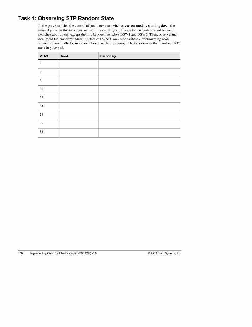
106 Implementing Cisco Switched Networks (SWITCH) v1.0 © 2009 Cisco Systems, Inc.
T by shutting down the
unusswitcdocuseconstate
ask 1: Observing STP Random State In the previous labs, the control of path between switches was ensured
ed ports. In this task, you will start by enabling all links between switches and between hes and routers, except the link between switches DSW1 and DSW2. Then, observe and ment the “random” (default) state of the STP on Cisco switches, documenting root, dary, and paths between switches. Use the following table to document the “random” STP in your pod.
VLAN Root Secondary
1
3
4
11
12
63
64
65
66

© 2009 Cisco Systems, Inc. Lab Guide 107
Spanniswitchin you
ng Tree calculation will occur the same way for all VLANs allowed on the same es. Use the following table to determine, for each group of VLANs and from each switch r network, which path is used to reach the root:
VLANs Switch Path to root
1, 3, 11 ASW1 , 63, 65
ASW2
DSW1
DSW2
CSW1
CSW2
4, 12, 6 66 ASW1 4,
ASW2
DS 1 W
DSW2
CSW1
CSW2

108 Implementing Cisco Switched Networks (SWITCH) v1.0 © 2009 Cisco Systems, Inc.
T
may desigsolutthis gto thedistriYou and 1secon
To he
ask 2: Create an Implementation Requirements List for MST According to the multivendor policy in the University, a set of switches from another vendor
be implemented in the University network. To prevent compatibility issues, you decide to n and migrate the existing random STP configuration towards Multiple-instance STP ion. This model will save CPU cycle by preventing per VLAN STP processing. To achieve oal, you have to mark the main requirements for the smooth migration to MST according constraints in the Information Packet. You need to decide on the number of instances, the bution of VLANs among instances, and the role of each switch in this new architecture. have to list the main requirements, e.g. DSW1 will be primary root switch for instances 0 and secondary for instance 2. The opposite with DSW2 – to be primary for instance 2 and dary for instances 0 and 1.
lp you, use the following table to report each switch role in the new architecture:
Device Device role MSTP instance VLANs

© 2009 Cisco Systems, In Lab Guide 109 c.
Once the objectirequirlab gu
MST switch roles are clear in your mind, use the following table, the initial lab visual ve, the implementation policy and devices information to create your implementation
ement list. If you are unsure, you can use the hints information provided at the end of the ide.
Device High level task Information source

110 Implementing co Switched Ne orks (SWITC ) v1.0 © 2009 Cisco Sy Inc. Cis tw H stems,
T
verifiwhicthe oimplefromVerifithis la
ask 3: Create Implementation and Verification Plan It is very important to establish a task list of the needed configurations and the possible
cations for every configuration change. It must be a detailed step-by-step list. The order in h each change should be applied is critical, since a successful implementation depends on rder. With the help of this list you can define configuration checkpoints. The actual mentation will be conducted in the next lab. Use the following table and the information
the Information Packet and the previous tasks to prepare your Implementation and cation plan. If you are unsure, you can use the hints information provided at the end of b.
Complete √
Device Implementation Order
Values and items to implement
Verification method and expected results

© 2009 Cisco Systems, Inc. Lab Guide 111
Complete √
Device ImplementationOrder
Values and items to implement
Verification method and expected results

112 Implementing C sco Switched Ne orks (SWITC ) v1.0 © 2009 Cisco Sy ems, Inc. i tw H st
Complete √
Device Implementation Order
Values and items to implement
Verification method and expected results

© 2009 Cisco Systems, Inc. Lab Guide 113
Complete √
Device ImplementationOrder
Values and items to implement
Verification method and expected results

114 Implementing Cisco Switched Networks (SWITCH) v1.0 © 2009 Cisco Systems, Inc.
Tplanned the implementation, you are ready
to cosolutspecicondyou a
ask 4: Implement and Verify Now that you have all of the requirements and have
nnect to the remote lab and implement your solution. Do not forget to save! Once your ion is implemented, verify your configuration is working and fulfills the requirements fied in the Information Packet. Use the previous table to document the verifications you ucted to ensure that your solution is complete. Hints are available at the end of this lab if re unsure about the verification steps.

© 2009 Cisco Systems, Inc. Lab Guide 115
Ste to document the details that you think are important to remember.
____
______
______
__________
__________________________________________________________________________
__________
______
______
______
__________________________________________________________________________
__________________________________________________________________________
______
______
______
__________
__________________________________________________________________________
__________
______
______
______
__________________________________________________________________________
__________________________________________________________________________
______
______
______
__________
udent Notes Use the following spac
______________________________________________________________________
____________________________________________________________________
____________________________________________________________________
________________________________________________________________
________________________________________________________________
____________________________________________________________________
____________________________________________________________________
____________________________________________________________________
____________________________________________________________________
____________________________________________________________________
____________________________________________________________________
________________________________________________________________
________________________________________________________________
____________________________________________________________________
____________________________________________________________________
____________________________________________________________________
____________________________________________________________________
____________________________________________________________________
____________________________________________________________________
________________________________________________________________

116 Implementing Cisco Switched Networks (SWITCH) v1.0 © 2009 Cisco Systems, Inc.
_____
__________________________________________________________________________
_____
_____
_____
_____
__________________________________________________________________________
__________________________________________________________________________
_____
_____
_____
_____
__________________________________________________________________________
_____
_____
_____
_____
__________________________________________________________________________
__________________________________________________________________________
_____
_____
_____
_____
__________________________________________________________________________
_____
_____
_____________________________________________________________________
_____________________________________________________________________
_____________________________________________________________________
_____________________________________________________________________
_____________________________________________________________________
_____________________________________________________________________
_____________________________________________________________________
_____________________________________________________________________
_____________________________________________________________________
_____________________________________________________________________
_____________________________________________________________________
_____________________________________________________________________
_____________________________________________________________________
_____________________________________________________________________
_____________________________________________________________________
_____________________________________________________________________
_____________________________________________________________________
_____________________________________________________________________
_____________________________________________________________________

© 2009 Cisco Systems, Inc. Lab Guide 117
Al
duringother p
_____ ________________________________________
______
______
__________________________________________________________________________
__________________________________________________________________________
______
______
______
__________
__________________________________________________________________________
__________
______
______
______
__________________________________________________________________________
__________________________________________________________________________
______
______
______
__________
__________________________________________________________________________
__________
______
______
______
ternate Resources and Solutions to the One You Used Other groups may use a solution different from yours. Possible solutions will be discussed
the debrief period after the lab. For your reference, use the following space to document ossible solutions.
_____________________________
____________________________________________________________________
____________________________________________________________________
____________________________________________________________________
____________________________________________________________________
____________________________________________________________________
________________________________________________________________
________________________________________________________________
____________________________________________________________________
____________________________________________________________________
____________________________________________________________________
____________________________________________________________________
____________________________________________________________________
____________________________________________________________________
________________________________________________________________
________________________________________________________________
____________________________________________________________________
____________________________________________________________________
____________________________________________________________________

118 Implementing Cisco Switched Networks (SWITCH) v1.0 © 2009 Cisco Systems, Inc.
_____
__________________________________________________________________________
_____
_____
_____
_____
__________________________________________________________________________
__________________________________________________________________________
_____
_____
_____
_____
__________________________________________________________________________
_____
_____
_____
_____
__________________________________________________________________________
__________________________________________________________________________
_____
_____
_____
_____
__________________________________________________________________________
_____
_____________________________________________________________________
_____________________________________________________________________
_____________________________________________________________________
_____________________________________________________________________
_____________________________________________________________________
_____________________________________________________________________
_____________________________________________________________________
_____________________________________________________________________
_____________________________________________________________________
_____________________________________________________________________
_____________________________________________________________________
_____________________________________________________________________
_____________________________________________________________________
_____________________________________________________________________
_____________________________________________________________________
_____________________________________________________________________
_____________________________________________________________________
_____________________________________________________________________

© 2009 Cisco Systems, Inc. Lab Guide 119
La_____________
______
______
______
__________
__________________________________________________________________________
__________
______
______
______
__________________________________________________________________________
__________________________________________________________________________
______
______
______
__________
__________________________________________________________________________
__________
______
______
______
__________________________________________________________________________
__________________________________________________________________________
______
______
______
__________
b 3-1: Key Commands and Tools Used _____________________________________________________________
____________________________________________________________________
____________________________________________________________________
____________________________________________________________________
________________________________________________________________
________________________________________________________________
____________________________________________________________________
____________________________________________________________________
____________________________________________________________________
____________________________________________________________________
____________________________________________________________________
____________________________________________________________________
________________________________________________________________
________________________________________________________________
____________________________________________________________________
____________________________________________________________________
____________________________________________________________________
____________________________________________________________________
____________________________________________________________________
____________________________________________________________________
________________________________________________________________

120 Implementing co Switched Networks ( 1.0 © 2009 Cisco Systems, Inc. Cis SWITCH) v
Hu are encouraged to complete the labs using your knowledge. If you need a tip, this section
conta
Lab 3-1 Hint Sh
Spthe following configuration. The actual configuration in
“random configuration” depends on the actual physical switc
ints Yo
ins a series of hints to help you complete the lab.
eet: Implement Multiple Spanning Tree
anning Tree Random State In a random state, STP could show your pod may be different, as the
hes that you are using.
VLAN Root Secondary
1 DSW2 CSW1
3 CSW1 DSW2
4 CSW1 DSW2
11 CSW1 DSW2
12 CSW1 DSW2
63 CSW1 DSW2
64 CSW1 DSW2
65 CSW1 DSW2
66 CSW1 DSW2
If the state of Spanning Tree” is as described in the above table, the path to root could be as follows:
“random
VLAN Switch Path to root
1, 3, 1 , 65 ASW1 Fa 0/1 1, 63
ASW2 Fa 0/2
DSW1 Po 31
D Po 32 SW2
CSW1 N/A
Po 33 CSW2
4, 12, 64, 66 ASW1 Fa 0/1
ASW2 Fa 0/2
DSW1 Po 31
DSW2 Po 32
CSW1 N/A
CSW2 Po 33

© 2009 Cisco Systems, Inc. Lab Guide 121
Step-Ste face in configuration mode.
.
Step 2 Enabl
Step 3 Repeat the
Step 4 Verify spa ample, on DSW2:
Root Hello Max Fwd
VLAN0 32 2 20 15 Fa0/5 VLAN0 32 2 20 15 Fa0/5 VLAN0VLAN0VLAN0VLAN0VLAN0VLAN0VLAN0
Design a MST SoThe fiInform
by-Step Procedure p 1 Connect to DSW1 switch inter
Connect to the remote lab.
Access the Switch console.
Enter privilege mode, using enable.
Enter configuration mode, using configure terminal
e previously shut ports:
DSW1(config)#interface range FastEthernet0/3 - 4 DSW1(config-if)# no shutdown
same process on switches DSW2, CSW1 and CSW2.
nning-tree root status on all switches. For ex
DSW2#sho spanning-tree root
Vlan Root ID Cost Time Age Dly Root Port -------------- ------------------ --------- ----- --- --- ------------
001 24577 001f.2721.8680 3 24579 001f.2721.8680 00
004 24580 001f.2721.8600 0 2 20 15 011 24587 001f.2721.8680 32 2 20 15 Fa0/5 012 24588 001f.2721.8600 0 2 20 15 063 24639 001f.2721.8680 32 2 20 15 Fa0/5 064 24640 001f.2721.8600 0 2 20 15 065 24641 001f.2721.8680 32 2 20 15 Fa0/5 066 24642 001f.2721.8600 0 2 20 15
lution for an L2 Network rst task is to decide which device has which role in which instance. Roles, as per the ation Packet, are as follows:
Device Device role MSTP instance VLANs
DSW1 primary root 0
primary root 1 1,3,11,63,65
secondary root 2 4,12,64,66
DSW 4,12,64,66 2 primary root 2
s ondary 0 ec root
ondary 1 sec root 1,3,11,63,65

122 Implementing Cisco Switched Networks (SWITCH) v1.0 © 2009 Cisco Systems, Inc.
Imour network, the first task asks you to create an
Impleimple
plementation Requirements To facilitate the configuration of y
mentation Requirements list. The list details the elements needed to develop an mentation plan. The following is an example of such a list:
Device Implementation Requirement Hint
Distribswitch
T conftances
entation po tion ution es
MSins
iguration – region 1, 0,1 and 2
Implem licy sec
Distribswitch
a mentation poution es
Primary nd secondary root bridges Imple licy section
Distribution switch
isw
n poles
VLAN dbridge s
tribution between the root itches
Implementatio icy section
All switch
Implementation policy section es
MST
All switches
fication Implementation policy section Veri

© 2009 Cisco Systems, Inc. Lab Guide 123
Device High level task Information source
DSW1 ion – region1, etwork Diagram, DMST configurat instance 1 N esign and Implementation Requirements
MST configuration – region1, instance 2 Network Diagram, D ntation Requirements
esign and Impleme
MST insta1,3,11,63,65
lemnce 1 assign odd VLANs - Design and Imp entation Requirements
MST insta4,12,64,6
Implemnce 2 assign even VLANs - 6
Design and entation Requirements
MST prim Implemary root for instance 1 Design and entation Requirements
MST seco nstance 2 Design and Implementation Requirements ndary root for i
DSW2 MST con ork Diagram, Direments
figuration – region1, instance 1 NetwRequ
esign and Implementation
MST con Diagram, Dfiguration – region1, instance 2 Network esign and Implementation Requirements
tanc1,3,11,63,65 MST ins e 1 assign odd VLANs - Design and Implementation Requirements
MST insta4,12,64,66
lemnce 2 assign even VLANs - Design and Imp entation Requirements
MST prim Implemary root for instance 2 Design and entation Requirements
MST seco tance 1 Design and Implementation Requirements ndary root for ins
ASW1 MST con0,1 and 2
Implemfiguration – region1, instances
Design and entation Requirements
MST instanc1,3,11,63
gn and Implementatioe 1 assign odd VLANs - ,65
Desi n Requirements
MST insta4,12,64,6
nd Implemnce 2 assign even VLANs - 6
Design a entation Requirements
ASW2 n0,1 and 2
plemMST co figuration – region1, instances
Design and Im entation Requirements
MST insta1,3,11,63
Implemnce 1 assign odd VLANs - ,65
Design and entation Requirements
MST instanc4,12,64,6
Implementatioe 2 assign even VLANs - 6
Design and n Requirements
CSW1 MST con on1, instances 2
Design and Implementation Requirements figuration – regi0,1 and
MST insta odd VLANs - 1,3,11,63,
Design and Implementation Requirements nce 1 assign65
MST insta4,12,64,6
Implemnce 2 assign even VLANs - 6
Design and entation Requirements
CSW2 MST con0,1 and 2
Implemfiguration – region1, instances
Design and entation Requirements
sta63
plemMST in1,3,11,
nce 1 assign odd VLANs - ,65
Design and Im entation Requirements
MST instanc even VLANs - 4,12,64,6
Design and Implementation Requirements e 2 assign6
Comment [A1]: This table doesn’t not have a title or lead-in.

124 Implementing co Switched Ne IT 1.0 © 2009 Cisco Systems, ICis tworks (SW CH) v nc.
Imn. There are several possible correct solutions.
One appliuniqu
plementation and Verification Plan In task 2, you will create an implementation pla
possible approach groups items that are common to all switches in a template and then es the template to all switches. You can then configure each switch with items that are e to each device. An example of the Implementation and Verification Plan follows.
Complete √
Device Implementation Order
Values and items to implement
Verification method and expected results
1. nding. DSW1 1 Mst instance Show pe
2 ign VLANs 1instance 1.
Show pending. Ass ,3,11,63,65 to
3 Mst instance 2. Show pending.
assign VLANs 4,instance 2.
4 12,64,66 to Show pending.
Change stp mo w spanning-tree. 5 de to mst. Sho
Primary root for tree 6 instances 0-1. Show spanning-root.
Secondary root for 7 instance 2. Show spanning-tree root.
DSW2 Mst instance 1. 8 Show pending.
9 Assign VLANs 1,3,11,63,65 to instance 1.
Show pending.
Mst instance 2. 10 Show pending.
Assign VLANs 4instance 2.
Show pending. 11 ,12,64,66 to
2 Change stp mo e. 1 de to mst. Show spanning-tre
13 Primary root for Show spanning-tree root.
instance 2.
4 Secondary root for 1.
Show spanning-tree 1 instances 0-root.
ASW1 16 Mst instance 1. Show pending.
7 Assign VLANs 1instance 1.
g. 1 ,3,11,63,65 to Show pendin
Mst instance 2. 18 Show pending.
19 Assign VLANs 4,12,64,66 to instance 2.
Show pending.
20 Change stp mo mst. Show spanning-tree. de to
ASW2 Mst instance 1. how pending. 21 S
2 Assign VLANs 1instance 1.
2 ,3,11,63,65 to Show pending.
Mst instance 2. Show pending. 23
4 Assign VLANs 4instance 2.
Show pending. 2 ,12,64,66 to
25 Change stp mo Show spanning-tree. de to mst.
CSW1 Mst instance 1. g. 26 Show pendin

© 2009 Cisco Systems, Inc. Lab Guide 125
Complete √
Device Implementation Order
Values and items to implement
Verification method and expected results
27 Assign VLANs 1,3,11,63,65 to instance 1.
Show pending.
28 Mst instance 2. Show pending.
assign VLANs 4,instance 2.
how pending. 29 12,64,66 to S
Change stp mod e. 30 e to mst. Show spanning-tre
CSW2 31 Mst instance 1. Show pending.
Assign VLANs 1instance 1.
. 32 ,3,11,63,65 to Show pending
33 Mst instance 2. w pending. Sho
Assign VLANs 4instance 2.
34 ,12,64,66 to Show pending.
Change stp mod how spanning-tree. 35 e to mst. S
Step-by-Step Proc dure Step 1 Enter MST configuration mode on switch DSW1:
DSW1(c ig)# span g-tree mst configuration
Step 2 Configure region name:
region1
DSW1(
Step 4 Put VLAN
1 vlan 1, 3, 11, 63, 65
Step 5 Put VLAN
nce 2 vlan 4, 12, 64, 66
Step 6 Show pendin
Name Revis
----- ---- 0
----- ---------------------------- DSW1(
Step 7 Change th
DSW1(
Step 8 Configure spanning-tree ro switch DSW1:
DSW1(
Step 9 Configure
DSW1( ary
e
onf nin
DSW1(config-mst)# name
Step 3 Configure revision:
config-mst)# revision 1
s 1,3,11,63 and 65 in instance 1:
DSW1(config-mst)# instance
s 4,12,64 and 66 in instance 2:
DSW1(config-mst)# insta
g to check the configuration:
config-mst)#sho pending DSW1(Pending MST configuration
[] ion 1 Instances configured 3
Instance Vlans mapped
--- -------------------------------------------------------- 2,5-10,13-62,67-4094
1 1,3,11,63,65 2 4,12,64,66
-------------------------------------config-mst)#
e stp mode to MST on switch DSW1:
config)# spanning-tree mode mst
ot primary for instance 0 and for instance 1 on
config)# spanning-tree mst 0-1 root primary
switch DWS1: spanning-tree root secondary for instance 2 on
oot secondconfig)# spanning-tree mst 2 r

126 Implementing Cisco Switched Networks (SWITCH) v1.0 © 2009 Cisco Systems, Inc.
Step 10 Verify spanning-tree root status:
DSW1#sho spanning-tree root oot Hello Max Fwd MST ----MST0MST1MST2
Step 11 Repeat st
Configur
primary
DSW2(c
Step 14 Verify sp
Cost Time Age Dly Root Port - --------- ----- --- --- ---------
MST0 0 2 20 15 Fa0/5 MST1 00000 2 20 15 Fa0/5 MST2
Step 15 Repeat st
Step 16 Repeat st
Step 17 Repeat st
Step 19 Verify spanning-tree root – repeat step 10.
1:
List ------------------
MST2 Po32
em : 1
RInstance Root ID Cost Time Age Dly Root Port ------------ ------------------ --------- ----- --- --- --------- 24576 001f.2721.8680 0 2 20 15 24577 001f.2721.8680 0 2 20 15 24578 001f.2721.8600 200000 2 20 15 Fa0/5
eps 1 to 7 on switch DSW2:
Step 12
D
e spanning-tree root primary for instance 2 on switch DWS2:
SW2(config)# spanning-tree mst 2 root
Step 13 Configure spanning-tree root secondary for instance 0 and for instance 1 on switch DSW2:
onfig)# spanning-tree mst 0-1 root secondary
anning-tree root status:
DSW2#sho spanning-tree root
Root Hello Max Fwd MST Instance Root ID ---------------- -----------------
24576 001f.2721.8680 24577 001f.2721.8680 2
24578 001f.2721.8600 0 2 20 15
eps 1 to 7 on switch �SW1.
eps 1 to 7 on switch �SW2.
eps 1 to 7 on switch CSW1.
Step 18 Repeat steps 1 to 7 on switch CSW2.
Step 20 Verify spanning-tree blocked ports on switch DSW
DSW1#sho spanning-tree blockedports Name Blocked Interfaces-------------------- ------------------
Number of blocked ports (segments) in the syst
Step 21 Repeat step 21 on all the rest switches.

© 2009 Cisco Syst Lab Guide 127 ems, Inc.
Lang Tree Protocol
implem
Activity Obj configuration was a success. You are asked to give another ST+. Here again, you decide that preparing a little bit for this
presensteps iPlus (Premoteadaptepresen
De
Cr
Im
an
Informati this activity. Read it carefully.
The rk,
Imtion to PVRST+. The following list details the preparation and
configimplem
Be channels enabled in lab 3-1 are still enabled. You need full and redundant connectivity for this lab. Only the link
d switch DSW2 must remain shut.
he primary root bridge for odd VLANs, switch DSW2 is to be the pri
Foro is primary root, switch DSW1 must be secondary root.
b 3-2: Implement PVRST+ Complete this lab activity to reinforce your understanding of Spanni
entation from the course.
ective Congratulations! Your MSTPpresentation focusing on PVR
tation could be useful, and that you would use your pod to walk through the different nvolved. In this activity, you will design and implement Per VLAN Rapid Spanning Tree VRST+) in Layer 2 topology. As you complete the design, you will connect to your lab to implement your solution. At the end of the lab, you will keep this solution best d to this lab environment. You will then have all the steps required to perform your live tation. After completing this activity, you will be able to meet these objectives:
sign a spanning tree
eate a spanning tree implementation plan
plement a spanning tree according to implementation plan
Create a spanning tree verification pl
Verify the spanning tree according to the verification plan
on Packet This packet contains the information needed to accomplish in
Information Packet describes the requirements common to all devices in the netwoalong with information specific to each device.
plementation Policy You will migrate your configura
uration requirements for all switches in the company network. Your configuration must ent all these requirements:
fore configuring and enabling spanning tree, verify that the Ether
between switch DSW1 an
Switch DSW1 is to be tmary root bridge for even VLANs.
r all VLANs for which switch DSW1 is primary root, switch DSW2 must be secondary ot. For all VLANs for which switch DSW2
The Device Information section describes the VLANs and corresponding roots.

128 Implementing ched Ne ITCH) v1.0 © 2009 Cisco Systems, Inc. Cisco Swit tworks (SW
Deve Layer 3 reachability information specific to each switch in the network:
ice Information The table provides th
Device name Role IP address Gateway VLAN
ASW1 2 ac itch 10.1.1.1/24 51 1 Layer cess sw 10.1.1.2
ASW2 Layer 2 access switch 10.1.1.2/24 10.1.1.252 1
DSW1 Layer 3 switch 10.1.1.11/24 10.1.1.251 1
DSW2 Layer 3 switch 10.1.1.22/24 10.1.1.252 1
CSW Layer 3 sw 0.1.1.111/24 251 1 1 itch 1 10.1.1.
CSW2 Layer 3 switch 10.1.1.222/24 10.1.1.252 1
R! Router a0/0: 10.1.1.251/24 1 F
R2 Router Fa0/0: 10.1.1.252/24 1
Links between switches sh ready be bundled toge s all possi umbering conve these link bundles. N num rs need used:
ould be alntions for
ther. The following table showote that NOT all of theseble n be
to be
Device Link to Bundle number should be:
ASW1 DSW1 11
ASW1 12 DSW2
ASW2 DSW1 11
ASW2 DSW2 12
DSW SW1 11 1 A
DSW SW2 12 1 A
DSW1 SW2 21 To remain down D shut
DSW1 W1 31 CS
DSW SW2 32 1 C
DSW2 ASW1 11
DSW2 ASW2 12
DSW2 DSW1 21 To remain shutdown
DSW2 CSW1 31
DSW2 CSW2 32
CSW SW1 31 1 D
CSW SW2 32 1 D
CSW SW2 33 1 C
CSW2 DSW1 31
CSW2 DSW2 32
CSW2 CSW1 33

VLAN Information
VLAN Root Backup
1 DSW1 DSW2
3 DSW1 DSW2
4 DSW2 DSW1
11 DSW1 DSW2
12 DSW2 DSW1
63 DSW1 DSW2
64 DSW2 DSW1
65 DSW1 DSW2
66 DSW2 DSW1
Network Diagram
© 2009
Visual Objective for Lab 3-2: Implement PVRST+
Cisco Systems, Inc. All rights reserved. SWITCH v1.0—18
© 2009 Cisco Systems, Inc. Lab Guide 129

130 Implementing Cisco Switched Networks (SWITCH) v1.0 © 2009 Cisco Systems, Inc.
Ce commands that you will use in this activity.
ommand List The table describes th
Command Description
name Specifies the c . The name string has a maximum lengt rs and is case sensitive.
name onfiguration nameh of 32 characte
show Shows your coconfiguration.
pending nfiguration by displaying the pending
show vlan-
Displays your spanning-tree vlanid
entries.
show s your entriespanning-tree summary Displays .
spannmst |
spanni
s efault setting).
t to enable MSTP (and RSTP).
ing-tree mode {pvst | rapid-pvst}
Configures ng-tree mode.
Select pv
Select ms
t to enable PVST+ (802,1D, the d
Select rapid-pvst to enable rapid PVST+
spanniroot primary [diameter net-diameter [hello-time seconds]]
Configures
mber of
(Optionasecmess 1 to 10; the default is 2.
ng-tree vlan vlan-id a switch to become the root for the specified VLAN.
For vlan-id, you can specify a single VLAN identified by VLAN ID number, a range of VLANs separated by a hyphen, or a series of VLANs separated by a comma. The range is 1 to 4094.
(Optional)nurange
For diameter net-diameter, specify the maximum switches between any two-end stations. The
is 2 to 7.
l) For hello-time seconds, specify the interval in onds between the generation of configuration
ages by the root switch. The range is
spanning-tree vlan vlan-id root secondary [diameter net-diameter [hello-time seconds]]
Configuresspecifie
For vlan-id, you can specify a single VLAN identified by
rang
(Optiona eter, specify the maximum number of switches between any two end stations. The
nal) , specify the interval in
def
a switch to become the secondary root for the d VLAN.
VLAN ID number, a range of VLANs separated by a hyphen, or a series of VLANs separated by a comma. The
e is 1 to 4094.
l) For diameter net-diam
range is 2
(Optioseconmessages
to 7.
For hello-time secondsds between the generation of configuration
by the root switch. The range is 1 to 10; the ault is 2.

© 2009 Cisco Systems, Inc. Lab Guide 131
Johe job aids for this lab activity:
b Aids These are t
Value Location
Blank im ation requirements list for PVRST
Task 1 plement+
Blank imform fo
plementation and verification plan r PVRST+
Task 2
Blank student notes Task 3
Implem nts Hint Section entation requirement hi
Implem Hint Section entation hints
Verifica int Section tion hints H
Solution configure answer key Configuration section at the end of the lab guide

132 Implementing Cisco Switched Networks (SWITCH) v1.0 © 2009 Cisco Systems, Inc.
TM
rk properly, but you like the idea of enhancing the efficiencygoal befordocuInfor
ask 1: Create an Implementation Requirements List for igration to PVRST+
Your MST configuration should wo of the convergence in case of a link failure. An efficient technology to achieve this
is to use PVRST+. This is why you want to migrate your network from MST to PVRST+ e presenting this solution during your next conference. Here again, you need to decide and ment which switch should be root for which VLAN. Use the following table and the mation Packet:
VLAN Root Secondary
1
3
4
11
12
63
64
65
66

© 2009 Cisco Systems, In Lab Guide 133 c.
At this point, your lab network has a functioning MST implementation and you are ready to migratdetailegather the en
e it to PVRST+. You have to make a list with the requirements in order to prepare a d implementation and verification plan in the next task. Use the Information Packet to the needed information. If you are unsure, you can use the hints information provided at
d of the lab guide.
Device High Level Task Information Source

134 Implementing co Switche tworks (SWITCH) v1.0 © 2009 Cisco Systems, Inc. Cis d Ne
Device High Level Task Information Source

© 2009 Cisco Systems, Inc. Lab Guide 135
TaSo
most important step in the planning process. Based on the information from the InformatVerifiprogredocumat the
sk 2: Create an Implementation and Verification Plan for your lution
This is theion Packet and the previous tasks, you must prepare a step-by-step Implementation and
cation plan. The task will help you setup configuration checkpoints to verify your ss. Use the plan to verify each item in the implementation. Use the following table to ent your steps in the correct order. If you are unsure, use the hints information provided
end of this lab.
Complete √
Device ImplementationOrder
Values and items to implement
Verification method and expected results

136 Implementing C sco Switched Ne orks (SWITC ) v1.0 © 2009 Cisco Sy ems, Inc. i tw H st
Complete √
Device Implementation Order
Values and items to implement
Verification method and expected results

© 2009 Cisco Systems, Inc. Lab Guide 137
Complete √
Device ImplementationOrder
Values and items to implement
Verification method and expected results

138 Implementing Cisco Switched Networks (SWITCH) v1.0 © 2009 Cisco Systems, Inc.
Complete √
Device Implementation Order
Values and items to implement
Verification method and expected results

© 2009 Cisco Systems, Inc. Lab Guide 139
Talanned the implementation, you are ready
to conthis PV
Once yrequirements specified in the Information Packet. Use the previous table to document the verificend of
sk 3: Implement and Verify Now that you have all of the requirements and have p
nect to the remote lab and implement your solution. Do not forget to save! You will keep RST+ configuration and use it for the subsequent labs.
our solution is implemented, verify your configuration is working and fulfills the
ations you conducted to ensure that your solution is complete. Hints are available at the this lab if you are unsure about the verification steps.

140 Implementing Cisco Switched Networks (SWITCH) v1.0 © 2009 Cisco Systems, Inc.
Sce to document the details that you think are important to remember.
___
_____
_____
_____
__________________________________________________________________________
_____
_____
_____
_____
__________________________________________________________________________
__________________________________________________________________________
_____
_____
_____
_____
__________________________________________________________________________
_____
_____
_____
_____
__________________________________________________________________________
__________________________________________________________________________
_____
_____
_____
_____
tudent Notes Use the following spa
_______________________________________________________________________
_____________________________________________________________________
_____________________________________________________________________
_____________________________________________________________________
_____________________________________________________________________
_____________________________________________________________________
_____________________________________________________________________
_____________________________________________________________________
_____________________________________________________________________
_____________________________________________________________________
_____________________________________________________________________
_____________________________________________________________________
_____________________________________________________________________
_____________________________________________________________________
_____________________________________________________________________
_____________________________________________________________________
_____________________________________________________________________
_____________________________________________________________________
_____________________________________________________________________
_____________________________________________________________________

© 2009 Cisco Systems, Inc. Lab Guide 141
__________
__________________________________________________________________________
__________
______
______
______
__________________________________________________________________________
__________________________________________________________________________
______
______
______
__________
__________________________________________________________________________
__________
______
______
______
__________________________________________________________________________
__________________________________________________________________________
______
______
______
__________
__________________________________________________________________________
__________
______
________________________________________________________________
________________________________________________________________
____________________________________________________________________
____________________________________________________________________
____________________________________________________________________
____________________________________________________________________
____________________________________________________________________
____________________________________________________________________
________________________________________________________________
________________________________________________________________
____________________________________________________________________
____________________________________________________________________
____________________________________________________________________
____________________________________________________________________
____________________________________________________________________
____________________________________________________________________
________________________________________________________________
________________________________________________________________
____________________________________________________________________

142 Implementing Cisco Switched Networks (SWITCH) v1.0 © 2009 Cisco Systems, Inc.
A
durinother
____ _________________________________________
_____
_____
__________________________________________________________________________
__________________________________________________________________________
_____
_____
_____
_____
__________________________________________________________________________
_____
_____
_____
_____
__________________________________________________________________________
__________________________________________________________________________
_____
_____
_____
_____
__________________________________________________________________________
_____
_____
_____
_____
lternate Resources and Solutions to the One You Used Other groups may use a solution different from yours. Possible solutions will be discussed
g the debrief period after the lab. For your reference, use the following space to document possible solutions.
_____________________________
_____________________________________________________________________
_____________________________________________________________________
_____________________________________________________________________
_____________________________________________________________________
_____________________________________________________________________
_____________________________________________________________________
_____________________________________________________________________
_____________________________________________________________________
_____________________________________________________________________
_____________________________________________________________________
_____________________________________________________________________
_____________________________________________________________________
_____________________________________________________________________
_____________________________________________________________________
_____________________________________________________________________
_____________________________________________________________________
_____________________________________________________________________
_____________________________________________________________________

© 2009 Cisco Systems, Inc. Lab Guide 143
__________
__________________________________________________________________________
__________
______
______
______
__________________________________________________________________________
__________________________________________________________________________
______
______
______
__________
__________________________________________________________________________
__________
______
______
______
__________________________________________________________________________
__________________________________________________________________________
______
______
______
__________
__________________________________________________________________________
__________
________________________________________________________________
________________________________________________________________
____________________________________________________________________
____________________________________________________________________
____________________________________________________________________
____________________________________________________________________
____________________________________________________________________
____________________________________________________________________
________________________________________________________________
________________________________________________________________
____________________________________________________________________
____________________________________________________________________
____________________________________________________________________
____________________________________________________________________
____________________________________________________________________
____________________________________________________________________
________________________________________________________________
________________________________________________________________

144 Implementing Cisco Switched Networks (SWITCH) v1.0 © 2009 Cisco Systems, Inc.
L______________
_____
_____
_____
_____
__________________________________________________________________________
_____
_____
_____
_____
__________________________________________________________________________
__________________________________________________________________________
_____
_____
_____
_____
__________________________________________________________________________
_____
_____
_____
_____
__________________________________________________________________________
__________________________________________________________________________
_____
_____
_____
_____
ab 3-2: Key Commands and Tools Used ____________________________________________________________
_____________________________________________________________________
_____________________________________________________________________
_____________________________________________________________________
_____________________________________________________________________
_____________________________________________________________________
_____________________________________________________________________
_____________________________________________________________________
_____________________________________________________________________
_____________________________________________________________________
_____________________________________________________________________
_____________________________________________________________________
_____________________________________________________________________
_____________________________________________________________________
_____________________________________________________________________
_____________________________________________________________________
_____________________________________________________________________
_____________________________________________________________________
_____________________________________________________________________
_____________________________________________________________________
_____________________________________________________________________

© 2009 Cisco Systems, Inc. Lab Guide 145
Hiu are encouraged to complete the labs using your knowledge. If you need a tip, this section
contai
Lab 3-2 Hint Sheet: Imple
De may be as follows:
nts Yo
ns a series of hints to help you complete the lab.
ment PVRST+
sign a PVRST+ Solution for an L2 Network When migrating from MSTP to PVRST+, the device role
Device Device role VLANs primary VLANs secondary
DSW1 STP root 1,3,11,63,65 4,12,64,66
DSW2 STP root 4,12,64,66 1,3,11,63,65
Implementation R ents To faci configura networ asks you to create an Implem irem list det s needed to develop an
is an example of such a list:
equiremlitate the entation Requ
tion of yourents list. The
k, the first taskails the element
implementation plan. The following
Device Implementation Requirement Hint
All switches
Change stp from mst to rapid-pvst. Implementation policy section
Distribution switches
Primary and secondary root bridge. Implementation policy section
Distribuswitche
N distrbridge swi
ntation poliction VLAs
ibution between the root Implemetches.
y section
All switche
ation. Implementation policy section s
Verific
Device High Level Task Information Source
DSW1 -tree mode Design and Implementation Requirements Spanning rapid-pvst
DSW1 -tree d Network Diagram, DesiRequirements
SpanningVLANs
primary root for od gn and Implementation
DSW1 Spanning-tree secondary root for even VLANs
Network Diagram, Design and Implementation Requirements
DSW2 g-tree mode Design and ImplemSpannin rapid-pvst entation Requirements
DSW2 g en
Network Diagram, ements
Spannin -tree primary root for evVLANs
Design and Implementation Requir
DSW2 ng-tree
iagram, Dnts
SpanniVLANs
secondary root for odd Network DRequireme
esign and Implementation
ASW1 Spanning rapid-pvst Design and Implem nts -tree mode entation Requireme
ASW2 ng emSpanni -tree mode rapid-pvst Design and Impl entation Requirements
CSW1 Spanning-tree mode rapid-pvst Design and Implem nts entation Requireme
CSW2 ng and ImplemSpanni -tree mode rapid-pvst Design entation Requirements

146 Implementing Cisco Switched Networks (SWITCH) v1.0 © 2009 Cisco Systems, Inc.
Imn. There are several possible correct solutions.
One appliuniqu
plementation and Verification Plan In task 2, you will create an implementation pla
possible approach groups items that are common to all switches in a template and then es the template to all switches. You can then configure each switch with items that are e to each device. An example of the Implementation and Verification Plan follows.
Complete √
Device Implementation Order
Values and items to implement
Verification method and expected results
mvst
g-tree. DSW1 1 Spanning-treep
ode rapid- Show spannin
spanning-tree vl1,3,11,63,65 roo
ro2 an t primary
Show spanning-tree ot.
3 spanning-tree vlan 4,12,64,66 root
Show spanning-tree vlan . secondary
4 No spanning-treconfiguration
e mst Show run.
DSW2 5 Spanning-tree mpvst
. ode rapid- Show spanning-tree
6 spanning-tree vl4,12,64,66 root
g-tree roan primary
Show spannin ot.
spanning-tree vl1,3,11,63,65 roosecondary
vl7 an t
Show spanning-tree an .
8 No spanning-treconfiguration
e mst Show run.
ASW1 9 Spanning-tree mpvst
ning-tree. ode rapid- Show span
10 No spanning-treconfiguration
e mst Show run.
ASW2 11 Spanning-tree mpvst
g-tree. ode rapid- Show spannin
No spanning-treconfiguration
12 e mst Show run.
CSW1 13 Spanning-tree modpvst
g-tree. e rapid- Show spannin
14 No spanning-treconfiguration
w run. e mst Sho
CSW2 15 Spanning-tree m pid-pvst
Show spanning-tree. ode ra
16 No spanning-treconfiguration
e mst Show run.
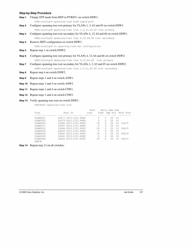
© 2009 Cisco Systems, Inc. Lab Guide 147
Step-Ste o PVRST+ on switch DSW1:
Step 2 Configure SW1:
DSW1(
DSW1(
Step 6 Configure
12,64,66 root primary
LANs 1, 3, 63 and 65 on switch DSW2:
Step 8 Repeat ste
Step 10 Repeat ste
DSW1#sho spanning-tree root
ot Hello Max Fwd Vlan Root ID Cost Time Age Dly Root Port
--- ----- --- --- --------- 0 2 20 15
2 20 15 2 20 15 Fa0/5
VLAN001 0 2 20 15 VLAN0 19 2 20 15 Fa0/5 VLAN0 0 2 20 15 VLAN0VLAN0VLAN0DSW1#
Step 14 Repeat ste
by-Step Procedure p 1 Change STP mode from MST t
DSW1(config)# spanning-tree mode rapid-pvst
spanning-tree root primary for VLANs 1, 3, 63 and 65 on switch D
DSW1(config)# spanning-tree vlan 1,3,11,63,65 root primary
Step 3 Configure spanning-tree root secondary for VLANs 4, 12, 64 and 66 on switch DSW1:
config)# spanning-tree vlan 4,12,64,66 root secondary
Step 4 Remove MST configuration on switch DSW1:
config)# no spanning-tree mst configuration
Step 5 Repeat step 1 on switch DSW2:
spanning-tree root primary for VLANs 4, 12, 64 and 66 on switch DSW2:
DSW2(config)# spanning-tree vlan 4,
Step 7 Configure spanning-tree root secondary for V
DSW2(config)# spanning-tree vlan 1,3,11,63,65 root secondary
p 4 on switch DSW2.
Step 9 Repeat steps 1 and 4 on switch ASW1.
ps 1 and 4 on switch ASW2.
Step 11 Repeat steps 1 and 4 on switch CSW1.
Step 12 Repeat steps 1 and 4 on switch CSW2.
Step 13 Verify spanning-tree root on switch DSW1:
Ro
---------------- ------------------ ------VLAN0001 24577 001f.2721.8680 VLAN0003 24579 001f.2721.8680 0VLAN0004 24580 001f.2721.8600 19
1 24587 001f.2721.8680 012 24588 001f.2721.8600
24639 001f.2721.8680 063 064 24640 001f.2721.8600 19 2 20 15 Fa0/5 065 24641 001f.2721.8680 0 2 20 15 066 24642 001f.2721.8600 19 2 20 15 Fa0/5
p 13 on all switches.

L
Activity Objective yze, locate, and fix STP problems on your network caused by rror. You should prepare a troubleshooting plan which will guide
you slearne
D
I
recommendations.
Visual Obj
ab 3-3: Troubleshooting Spanning Tree Issues Complete this lab activity to practice what you learned in the related module.
In this activity, you will analmisconfiguration or design e
tep-by-step in your efforts. You should be able to quickly fix the network using the skills d in this module. After completing this activity, you will be able to meet these objectives:
evelop a work plan to troubleshoot configuration and security issues, related to the STP.
solate the causes of the problems.
Correct all of the identified Spanning Tree issues.
Document and report the troubleshooting findings and
ective The figure illustrates what needs to be accomplished in this activity.
© 20
tive for Lab 3-3: Troubleshooting ee Issues
Visual ObjecSpanning Tr
09 Cisco Systems, Inc. All rights reserved. SWITCH v1.0—19
148 Implementing Cisco Switched Networks (SWITCH) v1.0 © 2009 Cisco Systems, Inc.

© 2009 Cisco Systems, Inc. Lab Guide 149
Co commands that are used in this activity.
Configuration Commands
mmand List The table describes the
Command Description
config Enters global config rom privileged EXEC mode, ure terminal uration mode f
enable ssword Enters the privile ommand interpreter. password pa ged EXEC mode c
inter| gigaslot/
ers interfacee
face fastethernet Entbitethernet port
with a Fast Eth configuration mode for a Cisco Catalyst switch rnet or Gigabit Ethernet interface installed.
spannienable
ng-tree bpdufilter
Enables BPDU filtering on an interface.
spannienable
les BPSU guard feature on an interface.. ng-tree bpduguard Enab
show sblocke
rtspanning-tree dports
Shows the po that are blocked by the spanning tree algorithm.
exit rrenExits the cu t mode.
Job Aids These jo o help you complete the lab activity.
Trou ets
Troubleshooting Log
Trouble Tickshort period of time. During your absence, your junior
network. The IT manager asked him to improve the behavior d as a result you saw a lot of error messages in the
logs of yo You are asked by the management to quickly correct the situation, as the network is very slow.
Trouble TickYour aswitchis to idDSW1 er paths.
b aids are available t
ble Tick
et A: Switch Optimization Gone Wrong You have been on a vacation for a colleague managed the switchedof the network. He made some changes an
ur switches on your arrival back.
Your task is to diagnose the issues and restore normal network operation.
et B: Unstable STP ssistant reports that ports are in an err-disabled state and that the link between the root es is down. The STP shows that no VLANs are blocked on the root switches. Your task entify the misconfigured item(s) and solve the issue(s) to recover connectivity between and DSW2 and ensure that the STP algorithm is enabling the prop

150 Implementing Cisco Switched Networks (SWITCH) v1.0 © 2009 Cisco Systems, Inc.
Inm the troubleshooting tickets, this troubleshooting lab contains two types of
issue
T involves error messages on several switches in the lab.
them. Together with your team members, create a troubleshooting plan to divide the work, assign memhelp troub
As difor thinstru
Oncetime indic
structions As you can see fro
s:
icket one
Ticket two involves problems with switch interfaces in error-disabled state.
Each ticket involves several switches, so the whole team has to work together to solve each of
each team member appropriate roles and coordinate device access between the team bers. Document your progress in the “Troubleshooting Log” provided below in order to facilitate efficient communication within the team and to have an overview of your leshooting process for reference during the lab debrief discussions.
fferent teams work at different speeds, this lab’s tickets are separated. To prepare the lab is exercise ask your instructor how you should initiate Trouble Ticket A. After the ctor indicates that the lab is fully prepared, you are ready to start troubleshooting.
you fix ticket A, ask your instructor if time is left for you to move on to the next ticket. If allows, ask your instructor how you should initiate Trouble Ticket B. After the instructor ates that the lab is fully prepared, you are ready to start troubleshooting.

© 2009 Cisco Systems, Inc. Lab Guide 151
Tr and results during the troubleshooting process.
oubleshooting Log Use this log to document your actions
Trouble Ticket
Actions and results

152 Implementing Cisco Switched Networks (SWITCH) v1.0 © 2009 Cisco Systems, Inc.
Trouble Ticket
Actions and results

© 2009 Cisco Systems, In Lab Guide 153 c.
Trouble Ticket
Actions and results

154 Implementing Cisco Switched Networks (SWITCH) v1.0 © 2009 Cisco Systems, Inc.
Trouble Ticket
Actions and results

© 2009 Cisco Systems, Inc. Lab Guide 155
Acn you attain the results below.
Trouble Ticket A: he L3 switches you can see no more error log entries generated.
Verify the STP status is the same as the end of Lab 3-1.
Trouble
opriate links are up.
tivity Verification You have completed this lab whe
Verify that on t
Verify that on the L2 switches you do not have ports in err-disabled state.
Ticket B: Verify the STP is blocking the correct VLANs on the root switches.
Verify the appr
Verif yy ou do not have ports in err-disabled state.

Tse and
resol
icket A: Sample Troubleshooting Flow The following pages illustrate an example of a method that you could follow to diagno
ve ticket A.
© 2009 Cisco Systems, Inc. All rights reserved. SWITCH v1.0—20
DSW1#show logg*Mar 6 18:10:41.823: %SW_MATM-4-MACFLAP_NOTIF: Host 0015.f904.bb2f in vlan 1 is flapping between port Po35 and port Fa0/5*Mar 6 18:10:41.823: %SW_MATM-4-MACFLAP_NOTIF: Host 0022.9042.2700 in vlan 1 is flapping between port Po35 and port Fa0/5
DSW2#show logg*Mar 6 18:10:41.823: %SW_MATM-4-MACFLAP_NOTIF: Host 0015.f904.bb2f in vlan 1 is flapping between port Po45 and port Fa0/5*Mar 6 18:10:41.823: %SW_MATM-4-MACFLAP_NOTIF: Host 0022.9042.2700 in vlan 1 is flapping between port Po45 and port Fa0/5
CSW1#show logg*Mar 6 18:10:41.823: %SW_MATM-4-MACFLAP_NOTIF: Host 0015.f904.bb2f in vlan 1 is flapping between port Po45 and port Po35*Mar 6 18:10:41.823: %SW_MATM-4-MACFLAP_NOTIF: Host 0022.9042.2700 in vlan 1 is flapping between port Po45 and port Po35
Key Clue: Error Logs on DSW1, DSW2 and CSW1
You have information for error log messages on your switches DSW1, DSW2 and CSW1.
natural first task is to access these devices and view the error messages.
an see that the error messages on the three switches are the same, regarding a flapping
The
You cMAC address of a host on EtherChannels and physical interfaces.
Reve
You and Dconnection between them. After this examination, you find out you have a switching loop.
A sw
The next
rt to the diagram, determine what links participate in these PortChannels and interfaces.
find out that the EtherChannels connect the Core switch CSW1 with the switches DSW1 SW2. You, also find out that the interfaces Fa 0/5 on both Distribution switches are the
itching loop is related to the functioning of the STP, in our case – PVRST+.
logical step is to check the PVRST+ on the affected interfaces.
156 Implementing Cisco Switched Networks (SWITCH) v1.0 © 2009 Cisco Systems, Inc.

© 2009 Cisco Systems, Inc. All rights reserved. SWITCH v1.0—21
DSW1#show spanning-tree interface port-channel 31
Vlan Role Sts Cost Prio.Nbr Type
------------------- ---- --- --------- -------- ------------------------
VLAN0001 Desg FWD 12 128.296 P2p
VLAN0003 Desg FWD 12 128.296 P2p
VLAN0004 Root FWD 12 128.296 P2p
VLAN0011 Desg FWD 12 128.296 P2p
VLAN0012 Root FWD 12 128.296 P2p
VLAN0063 Desg FWD 12 128.296 P2p
VLAN0064 Root FWD 12 128.296 P2p
VLAN0065 Desg FWD 12 128.296 P2p
VLAN0066 Root FWD 12 128.296 P2p
Key Clue: Observe STP on Suspicious Ports
© 2009 Cisco Systems, Inc. Lab Guide 157

© 2009 Cisco Systems, Inc. All rights reserved. SWITCH v1.0—22
Key Clue: Observe STP on Suspicious Ports
You ca
You seinte
Proceed to the next switch.
n verify the STP state for the affected interfaces, e.g. Po31 and Fa0/5, on DSW1.
e that the STP state for interface Po31 looks normal, but the information returned for rface Fa0/5 is more confusing. The same strange information appears on CSW2 Po33.
Key Clue: Observe STP on Suspicious Ports
© 2009 Cisco Systems, Inc. All rights reserved. SWITCH v1.0—23
158 Implementing Cisco Switched Networks (SWITCH) v1.0 © 2009 Cisco Systems, Inc.

© 2009 Cisco Systems, Inc. All rights reserved. SWITCH v1.0—24
DSW2#sho spanning-tree interface FastEthernet 0/5
Vlan Role Sts Cost Prio.Nbr Type
------------------- ---- --- --------- -------- --------------------------------
VLAN0001 Desg FWD 19 128.7 P2p
VLAN0003 Desg FWD 19 128.7 P2p
VLAN0004 Desg FWD 19 128.7 P2p
VLAN0011 Desg FWD 19 128.7 P2p
VLAN0012 Desg FWD 19 128.7 P2p
VLAN0063 Desg FWD 19 128.7 P2p
VLAN0064 Desg FWD 19 128.7 P2p
VLAN0065 Desg FWD 19 128.7 P2p
VLAN0066 Desg FWD 19 128.7 P2p
DSW2#
Key Clue: Observe STP on Suspicious Ports
You
He
Your next logical step is to analyze the interface Fa0/5, as its state looks different from the others.
check the STP state for the affected interfaces, e.g. Po31 and Fa0/5, on DSW2.
re the situation is the same as it is on DSW1.
© 2009 Cisco Systems, Inc. Lab Guide 159

© 2009 Cisco Systems, Inc. All rights reserved. SWITCH v1.0—25
DSW1#sho spanning-tree interface FastEthernet 0/5 detail
Port 7 (FastEthernet0/5) of VLAN0001 is designated forwarding
Port path cost 19, Port priority 128, Port Identifier 128.7.
Designated root has priority 24577, address 001f.2721.8680
Designated bridge has priority 24577, address 001f.2721.8680
Designated port id is 128.7, designated path cost 0
Timers: message age 0, forward delay 0, hold 0
Number of transitions to forwarding state: 1
Link type is point-to-point by default
Bpdu filter is enabled
BPDU: sent 260, received 9
Key Clue: Observe STP on Suspicious Ports
You ch
DSW1 Por Po Designated root has priority 24577, address 001f.2721.8680 Designated bridge has priority 24577, address 001f.2721.8680 D T N L B B
You
Sinceinterf
ecked the STP for the interface Fa0/5 on DSW1.
#sho spanning-tree interface FastEthernet 0/5 detail t 7 (FastEthernet0/5) of VLAN0001 is designated forwarding rt path cost 19, Port priority 128, Port Identifier 128.7.
esignated port id is 128.7, designated path cost 0 imers: message age 0, forward delay 0, hold 0 umber of transitions to forwarding state: 1 ink type is point-to-point by default pdu filter is enabled PDU: sent 260, received 9
see that on interface Fa0/5 you have the bpdu filter feature enabled!
this is a feature that relates to access ports, preventing the BPDUs, and is a trunk ace, you understand that this is a problem.
160 Implementing Cisco Switched Networks (SWITCH) v1.0 © 2009 Cisco Systems, Inc.

© 2009 Cisco Systems, Inc. All rights reserved. SWITCH v1.0—26
Key Clue: Check Why DSW2 Don’t Receive BPDU from DSW1
Check t
DSW1#inter span
You found a wrong configuration issue regarding STP security feature.
he configuration of the interface Fa0/5 on DSW1 to verify you have hit the problem:
show run interface fastEthernet 0/5 face fastEthernet 0/5 ning-tree bpdufilter enable
© 2009 Cisco Systems, Inc. Lab Guide 161

© 2009 Cisco Systems, Inc. All rights reserved. SWITCH v1.0—27
DSW1#conf t
Enter configuration commands, one per line. End with CNTL/Z.
DSW1(config)#interface fastEthernet 0/5
DSW1(config-if)#no spanning-tree bpdufilter enable
Key Clue: Configure DSW1
You have to correct the configuration:
#conf t r configuration commands, one per line. End with CNTL/Z. (config)#interface fastEthernet 0/5
DSW1EnteDSW1DSW1(config-if)#no spanning-tree bpdufilter enable
162 Implementing Cisco Switched Networks (SWITCH) v1.0 © 2009 Cisco Systems, Inc.

© 2009 Cisco Systems, Inc. All rights reserved. SWITCH v1.0—28
Key Clue: Check DSW1
The s
Veri
DSW1#Vlan Role Sts Cost Prio.Nbr Type ------------------- ---- --- --------- -------- ------------------- VLAN0VLAN000VLAN0004 Root FWD 19 128.7 P2p VLAN0VLAN001VLAN0VLAN0VLAN0VLAN0
Additi ssages in thei
ame issue appears on CSW2 Po33 link. Resolve it the same way.
fy the STP is back to normal and you have corrected the problem:
sho spanning-tree interface FastEthernet 0/5
001 Desg FWD 19 128.7 P2p 3 Desg FWD 19 128.7 P2p
011 Desg FWD 19 128.7 P2p 2 Root FWD 19 128.7 P2p
063 Desg FWD 19 128.7 P2p 064 Root FWD 19 128.7 P2p 065 Desg FWD 19 128.7 P2p 066 Root FWD 19 128.7 P2p
onally, you can go to the switches again and check that there are no new error mer logs.
© 2009 Cisco Systems, Inc. Lab Guide 163

© 2009 Cisco Systems, Inc. All rights reserved. SWITCH v1.0—29
Key Clue: Check DSW1
Verify i
DSW1 Por P Designated root has priority 24577, address 001f.2721.8680 Designated bridge has priority 24577, address 001f.2721.8680 D T N L B
Addiin the
f the STP state shows that the bpdu filter feature is not enabled anymore:
#sho spanning-tree interface FastEthernet 0/5 detail t 7 (FastEthernet0/5) of VLAN0001 is designated forwarding ort path cost 19, Port priority 128, Port Identifier 128.7.
esignated port id is 128.7, designated path cost 0 imers: message age 0, forward delay 0, hold 0 umber of transitions to forwarding state: 1 ink type is point-to-point by default PDU: sent 284, received 12
tionally, you can go to the switches again and check that there are no new error messages ir logs.
164 Implementing Cisco Switched Networks (SWITCH) v1.0 © 2009 Cisco Systems, Inc.

© 2009 Cisco Systems, Inc. Lab Guide 165
Al
duringother p
____ _____________________________________________
______
__________
__________________________________________________________________________
__________
______
______
______
__________________________________________________________________________
__________________________________________________________________________
______
______
______
__________
__________________________________________________________________________
__________
______
______
______
__________________________________________________________________________
__________________________________________________________________________
______
______
______
__________
ternate Resources and Solutions to the One You Used Other groups may use a solution different from yours. Possible solutions will be discussed
the debrief period after the lab. For your reference, use the following space to document ossible solutions.
_________________________
____________________________________________________________________
________________________________________________________________
________________________________________________________________
____________________________________________________________________
____________________________________________________________________
____________________________________________________________________
____________________________________________________________________
____________________________________________________________________
____________________________________________________________________
________________________________________________________________
________________________________________________________________
____________________________________________________________________
____________________________________________________________________
____________________________________________________________________
____________________________________________________________________
____________________________________________________________________
____________________________________________________________________
________________________________________________________________

166 Implementing Cisco Switched Networks (SWITCH) v1.0 © 2009 Cisco Systems, Inc.
_____
__________________________________________________________________________
_____
_____
_____
_____
__________________________________________________________________________
__________________________________________________________________________
_____
_____
_____
_____
__________________________________________________________________________
_____
_____
_____
_____
__________________________________________________________________________
__________________________________________________________________________
_____
_____
_____
_____
__________________________________________________________________________
_____
_____
_____
_____
_____________________________________________________________________
_____________________________________________________________________
_____________________________________________________________________
_____________________________________________________________________
_____________________________________________________________________
_____________________________________________________________________
_____________________________________________________________________
_____________________________________________________________________
_____________________________________________________________________
_____________________________________________________________________
_____________________________________________________________________
_____________________________________________________________________
_____________________________________________________________________
_____________________________________________________________________
_____________________________________________________________________
_____________________________________________________________________
_____________________________________________________________________
_____________________________________________________________________
_____________________________________________________________________
_____________________________________________________________________
_____________________________________________________________________

Ti to diagnose and
resolv
cket B: Sample Troubleshooting Flow The following pages illustrate an example of a method that you could follow
e ticket B.
© 2009 Cisco Systems, Inc. All rights reserved. SWITCH v1.0—30
Key Clue: STP on DSW1
You c
On DSW1
DSW1#Name -------------------- ------------------------------------ Number of blocked ports (segments) in the system : 0 DSW1#FastE Hardware is Fast Ethernet, address is 001f.2721.8687 (bia 001f.2721.8687) MTU Enc Kee Aut inp.
heck the reported switches for the blocked port and the STP status.
you find that Fa0/5 is in err-disabled state and that the STP is not blocking VLANs:
sh spanning-tree blockedports Blocked Interfaces List
sho int fa 0/5 thernet0/5 is down, line protocol is down (err-disabled)
1500 bytes, BW 10000 Kbit, DLY 1000 usec, reliability 255/255, txload 1/255, rxload 1/255 apsulation ARPA, loopback not set palive set (10 sec) o-duplex, Auto-speed, media type is 10/100BaseTX ut flow-control is off, output flow-control is unsupported
© 2009 Cisco Systems, Inc. Lab Guide 167

© 2009 Cisco Systems, Inc. All rights reserved. SWITCH v1.0—31
Key Clue: STP on DSW2
You find a similar situation on DSW2. Port Fa0/5 is in state notconnect and the STP is not ing VLANs, as expected:
#sho spanning-tree blockedports Blocked Interfaces List
block
DSW2Name-------------------- ------------------------------------ Number of blocked ports (segments) in the system : 0 DSW2Fast Ha is 001f.2721.8607 (bia 001f.2721.8607) MTU 150 5
You
You t place to look
#sho int fa 0/5 Ethernet0/5 is down, line protocol is down (notconnect) rdware is Fast Ethernet, address
0 bytes, BW 100000 Kbit, DLY 100 usec, reliability 255/255, txload 1/255, rxload 1/25
have a problem with the STP. It is not blocking VLANs as expected.
find out that you need more information to hit the problem. The most natural firsis the log.
168 Implementing Cisco Switched Networks (SWITCH) v1.0 © 2009 Cisco Systems, Inc.

© 2009 Cisco Systems, Inc. All rights reserved. SWITCH v1.0—32
Key Clue: Logs on DSW1
The log on DSW1 clearly shows you the problem – a security spanning-tree feature, in our case duguard has put the Fa0/5 in err-disabled state, as BPDUs appeared on this interface.
it is normal to have BPDUs sent and received on this interface, you check the
the bp
Since configuration of this interface.
© 2009 Cisco Systems, Inc. Lab Guide 169

© 2009 Cisco Systems, Inc. All rights reserved. SWITCH v1.0—33
Key Clue: Check Fa0/5 on CSW1
Your
DSW1BuilCurr! interface FastEthernet0/5 swi swi swi spaend
You rt.
You
The n rmine if this is the p
check of interface Fa0/5 shows the following:
#sho run int Fa0/5 ding configuration... ent configuration : 175 bytes
tchport trunk encapsulation dot1q tchport trunk allowed vlan 1,3,4,11,12,63-66 tchport mode trunk nning-tree bpduguard enable
find the bpdu guard feature configured on a trunk po
found a problem.
ext steps involve correction of the mistaken configuration and tests to deteroblem.
170 Implementing Cisco Switched Networks (SWITCH) v1.0 © 2009 Cisco Systems, Inc.
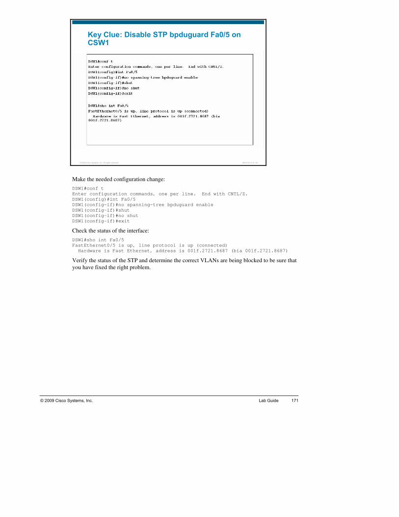
© 2009 Cisco Systems, Inc. All rights reserved. SWITCH v1.0—34
Key Clue: Disable STP bpduguard Fa0/5 on CSW1
Ma
DSW1#EnterDSW1(DSW1(config-if)#no spanning-tree bpduguard enable DSW1(config-if)#shut DSW1(DSW1(
Check erface:
DSW1#FastE Har 1.8687)
Verify he correct VLANs are being blocked to be sure that you ha
ke the needed configuration change:
conf t configuration commands, one per line. End with CNTL/Z. config)#int Fa0/5
config-if)#no shut config-if)#exit
the status of the int
sho int Fa0/5 thernet0/5 is up, line protocol is up (connected) dware is Fast Ethernet, address is 001f.2721.8687 (bia 001f.272
the status of the STP and determine tve fixed the right problem.
© 2009 Cisco Systems, Inc. Lab Guide 171

© 2009 Cisco Systems, Inc. All rights reserved. SWITCH v1.0—35
Key Clue: Check STP
The c
DSW1Name----VLAN0004 Po31 VLAN0012 Po31 VLANVLANNumb 4 DSW2Name----VLANVLANVLANVLANVLANNumb
As th
hecks are successful:
#sho spanning-tree blockedports Blocked Interfaces List ---------------- ------------------------------------
0064 Po31 0066 Po31 er of blocked ports (segments) in the system : #sho spanning-tree blockedports Blocked Interfaces List ---------------- ------------------------------------ 0001 Po32 0003 Po32 0011 Po32 0063 Po32 0065 Po32 er of blocked ports (segments) in the system : 5
e verification has been successful you have to document your findings.
172 Implementing Cisco Switched Networks (SWITCH) v1.0 © 2009 Cisco Systems, Inc.

© 2009 Cisco Systems, Inc. Lab Guide 173
Al
duringother p
_____ ________________________________________
______
__________
__________________________________________________________________________
__________
______
______
______
__________________________________________________________________________
__________________________________________________________________________
______
______
______
__________
__________________________________________________________________________
__________
______
______
______
__________________________________________________________________________
__________________________________________________________________________
______
______
______
__________
ternate Resources and Solutions to the One You Used Other groups may use a solution different from yours. Possible solutions will be discussed
the debrief period after the lab. For your reference, use the following space to document ossible solutions.
_____________________________
____________________________________________________________________
________________________________________________________________
________________________________________________________________
____________________________________________________________________
____________________________________________________________________
____________________________________________________________________
____________________________________________________________________
____________________________________________________________________
____________________________________________________________________
________________________________________________________________
________________________________________________________________
____________________________________________________________________
____________________________________________________________________
____________________________________________________________________
____________________________________________________________________
____________________________________________________________________
____________________________________________________________________
________________________________________________________________

174 Implementing Cisco Switched Networks (SWITCH) v1.0 © 2009 Cisco Systems, Inc.
_____
__________________________________________________________________________
_____
_____
_____
_____
__________________________________________________________________________
__________________________________________________________________________
_____
_____
_____
_____
__________________________________________________________________________
_____
_____
_____
_____
__________________________________________________________________________
__________________________________________________________________________
_____
_____
_____
_____
__________________________________________________________________________
_____
_____________________________________________________________________
_____________________________________________________________________
_____________________________________________________________________
_____________________________________________________________________
_____________________________________________________________________
_____________________________________________________________________
_____________________________________________________________________
_____________________________________________________________________
_____________________________________________________________________
_____________________________________________________________________
_____________________________________________________________________
_____________________________________________________________________
_____________________________________________________________________
_____________________________________________________________________
_____________________________________________________________________
_____________________________________________________________________
_____________________________________________________________________
_____________________________________________________________________

© 2009 Cisco Systems, Inc. Lab Guide 175
La_____________
______
______
______
__________
__________________________________________________________________________
__________
______
______
______
__________________________________________________________________________
__________________________________________________________________________
______
______
______
__________
__________________________________________________________________________
__________
______
______
______
__________________________________________________________________________
__________________________________________________________________________
______
______
______
__________
b 3-3: Key Commands and Tools Used _____________________________________________________________
____________________________________________________________________
____________________________________________________________________
____________________________________________________________________
________________________________________________________________
________________________________________________________________
____________________________________________________________________
____________________________________________________________________
____________________________________________________________________
____________________________________________________________________
____________________________________________________________________
____________________________________________________________________
________________________________________________________________
________________________________________________________________
____________________________________________________________________
____________________________________________________________________
____________________________________________________________________
____________________________________________________________________
____________________________________________________________________
____________________________________________________________________
________________________________________________________________

176 Implementing Cisco Switched Networks (SWITCH) v1.0 © 2009 Cisco Systems, Inc.
LVLA
Activity Objective ntinues to grow the demands for expansion, better convergence and ager to ask you for a solution for the migration towards a Layer 3
Core impleoperaEIGRLayefor yimpleobject
D
C
C -step implementation and verification plan.
ng and routing protocols.
ab 4-1: Implement Inter-VLAN Routing Complete this lab activity to confirm your knowledge from the course on the topics of inter-
N routing and routing protocols.
As the corporate network coreliability drove your IT man
and Distribution design. He insisted on using dynamic routing protocol, to ease the mentation of new networks, thus reducing the possibility of mistakes and risks of tion failures. The specifications given to you from the IT manager clearly state the use of P as routing protocol and implementation of separate networks on the links between the
r 3 switches. The distribution switches must become the new gateways and DHCP servers our access layer. Once the design is complete, you will connect to your remote lab to ment your solution. After completing this activity, you will be able to meet these ives:
esign an L3 network.
reate an implementation requirements list.
reate a step-by
Implement and verify Inter-VLAN routi
© 2009 Cisco Systems, Inc. Lab Guide 177
Intion needed to accomplish in this activity. Read it carefully.
The Inalong
ImplementationVLAN routing and a routing protocol in your network. The
ing preparation and routing configuration requirements for all switchrequir
Co
Co ces between switches DSW1 and DSW2 to become L3 links. Enable this li
s for data VLANs on both distribution switches according to the
Change management VLAN on Access switches from VLAN 1 to first data VLAN (VLAN
ces
CLT2 must obtain their IP address
formation Packet This packet contains the informa
formation Packet describes the requirements common to all devices in the network, with information specific to each device.
Policy You have to configure inter-following list details regard
es in the company network. Your configuration must implement all of these ements:
nfigure all interfaces between the Distribution and Core switches to become L3 links.
nfigure the interfank.
Configure the links between the core switches and the routers to become L3.
Use the networks from the table provided below for the L3 links.
Setup SVI interfaceinformation provided in the Device Information section.
3 or VLAN 4 depending on devices). You need to create an SVI for this VLAN. The IP addresses for your switches will change. For example, if your device VLAN 1 IP address was in 10.1.1.0/24, VLAN 1 will no longer have an IP address, and VLAN 3 IP address will be in 10.1.3.0/24. Apply this rule to all of your devices. Refer to the DeviInformation section to know which IP address should be used on which switch.
Remove the management VLAN 1 IP address on Distribution switches, as you can manage them via any routed interface or SVI.
Switches DSW1 and DSW2 will be default gateways for the clients and the access switches. Switch DSW1 will be the default gateway for switches ASW1 and CLT1, switch DSW2 will be the default gateway for switch ASW2 and client CLT2.
Configure DHCP services on switches DSW1 and DSW2 for networks 10.1.3.0/24 and 10.1.4.0/24. Switch DSW1 must allocate addresses 50 to 99 and DSW2 must allocate addresses 100 to 149 for each scope. Clients CLT 1 andfrom switch DSW1 or switch DSW2.
Remove DHCP service and sub-interfaces from routers R1 and R2.
Configure EIGRP AS 10 on the Core and Distribution switches and the Routers.
Execute the Verification plan to ensure IP connectivity.

178 Implementing Cis d Netw TCH) v1.0 © 2009 Cisco Systems, Inc. co Switche orks (SWI
Devnformation specific to the devices in the network. These subnets use
a /31reser
ices Information The table provides the L3 i
(255.255.255.254) mask, using RFC 3021 specifications. Notice that this type of mask is ved for point-to-point links, which is the case here:
Device name L3 interface IP address
DSW1 10.1.253.0/31 Po 31
DSW1 10.1.253.2/31 Po 32
DSW1 P3 10.1.253.4/31
DSW2 Po 31 10.1.253.6/31
DSW2 Po 32 10.1.253.8/31
DSW2 P3 10.1.253.5/31
CSW1 Po 31 10.1.253.1/31
CSW1 Po 32 10.1.253.9/31
CSW1 Po 33 10.1.253.10/31
CSW1 P1 10.1.253.12/31
CSW1 P2 10.1.253.14/31
CSW2 Po 31 10.1.253.7/31
CSW2 Po 32 10.1.253.3/31
CSW2 Po 33 10.1.253.11/31
CSW2 P1 10.1.253.16/31
CSW2 P2 10.1.253.18/31
R1 P1 10.1.253.13/31
R1 P2 10.1.253.19/31
R2 P1 10.1.253.17/31
R2 P2 10.1.253.15/31
This tab ovides IP addressing information regarding the ches: le pr SVI interfaces on the swit
Device SVI IP address
ASW1 VLAN 3 10.1.3.10/24
ASW2 VLAN 4 10.1.4.20/24
DS VLAN 3 10.1.3.1/24 W1
DSW1 VLAN 4 10.1.4.1/24
DSW2 VLAN 3 10.1.3.2/24
DSW2 VLAN 4 10.1.4.2/24

Network Diagram
© 2009 Cisco Systems, Inc. All rights reserved. SWITCH v1.0—36
Visual Objective for Lab 4-1: Implementing Inter-VLAN Routing
© 2009 Cisco Systems, Inc. Lab Guide 179

180 Implementing 0 Cisco Switched Networks (SWITCH) v1. © 2009 Cisco Systems, Inc.
Ce commands that are used in this activity.
ommand List The table describes th
Command Description
chan hannel-group-n de {auto [non-[non-pass
Assigns the po p, and specify the PAgP or the LACP mode.
de, sele
to—Enab e is detected. It the rt re
desiport into neg
on—Forc
grouthe on mod
modcapThe sana to operate, to attach h
activdetin wsen
passipasLAC not start LACP pac
nel-group cumber mo
silent] | desirable silent] | on} | {active | ive}
For mo
auplacesthe postart
rt to a channel grou
ct one of these keywords:
les PAgP only if a PAgP devicport into a passive negotiating state, in which
sponds to PAgP packets it receives but does not PAgP packet negotiation.
rable—Unconditionally enables PAgP. It places the an active negotiating state, in which the port starts
otiations with other ports by sending PAgP packets.
es the port to channel without PAgP or LACP. In the on mode, an EtherChannel exists only when a port
p in the on mode is connected to another port group in e.
non-silent—(Optional) Configure the switch port for nonsilent operation when the port is in the auto or desirable
e, if your switch is connected to a partner that is PAgP able,. If you do not specify non-silent, silent is assumed.
ilent setting is for connections to file servers or packet lyzers. This setting allows PAgP
t e port to a channel group, and to use the port for transmission.
e—Enables LACP only if a LACP device is ected. It places the port into an active negotiating state hich the port starts negotiations with other ports by ding LACP packets.
ve—Enables LACP on the port and places it into a sive negotiating state in which the port responds to P packets that it receives, but does
ket negotiation.
default-router address [address2 ... address8]
(Optional) DHCP cl
The s the client.
routersthe mospreferre
Specifies the IP address of the default router for a ient.
IP address should be on the same subnet a
One IP address is required; however, you can specify a up to eight IP addresses in one command line. These default
are listed in order of preference; that is, address is t preferred router, address2 is the next most d router, and so on.
doma he din-name domain Specifies t omain name for the client.
config al c from privileged EXEC mode. ure terminal Enters glob onfiguration mode
enable password password Enters the privileged EXEC mode command interpreter.
interface interface-id Specify a physical port, and enter interface configuration mode.
interface port-channel port-channel-number
Specify the pconfiguratio
ort-channel logical interface, and enter interface n mode.
ip address ip-address mask
Assigns an IP address and subnet mask to the EtherChannel.
ip rou Enables IP routing ting.

© 2009 Cisco Systems, Inc Lab Guide 181 .
Command Description
ip dhcp excluded-address low-aaddre
Specifies the IP addresses that the DHCP server should not CPddress [high-
ss] assign to DH clients.
ip dh
reates a name for the DHCP server address pool and enters DHCP pool configuration mode.
cp pool name C
lease[minutes]| infinite}
ptional) Speci
The default is a one-day lease.
The infinite is unlimited.
{days [hours] (O fies the duration of the lease.
keyword specifies that the duration of the lease
network network-number [mask | /prefix-length]
Specifies the subnet network number and mask of the DHCP address pool.
network mber Associates ting process. EIGRP to network-nu sends updates
networks with an EIGRP routhe interfaces in the specified networks.
no au isab-level routesto-summary (Optional) D
into networkles automatic summarization of subnet routes
.
no ip hat the address Ensures tport.
re is no IP address assigned to the physical
no sw Places the interfitchport ace into Layer 3 mode.
router eigrpsyste
Enables an EIG ter configuration mode. Tother EIGRP rou
autonomous-m number
RP routing process, and enter rouhe AS number identifies the routes to
ters and tags routing information.
show ethchanndetai
Shows your entrieserchannel el-group-number l
.
show hich iP relip eigrp interface Displays w
about EIGRnterfaces EIGRP is active on and information ating to those interfaces.
show ip protocols Shows your entries.
show lays the cur le. ip route Disp rent state of the routing tab
Job Aids These are the job aids for this lab activity:
Value Location
Blank Ta design requirements list sk 1
Blank ents list Ta implementation requirem sk 2
Blank implementation and verification plan form Task 3
Blank student notes Task 4
Debri lab ef alternate solutions form End of this
Implem equirement hints Hint Section entation r
Impleme Hint Section ntation hints
Verifica Hint Section tion hints
Solution nfiguration sectio d of the lab guide configure answer key Co n at the en

182 Implementing Cisco Switched Networks (SWITCH) v1.0 © 2009 Cisco Systems, Inc.
Tthe network. You have to decide on
the Inthe cchang
ask 1: Create a Layer 3 Design You have to create your design for the migration to L3 in
ter-VLAN routing and on the use of EIGRP as a routing protocol. You have to consider hanges in the links between the Core and Distribution switches, the changes in DHCP, the es in VTP. Use the table below to create the expected design.
Complete √
Device SVI interfaces L3 interfaces Is the device a DHCP server?
EIGRP AS No (if applicable)

© 2009 Cisco Systems, Inc. Lab Guide 183
TaIn
n, it is time to create a list in which you will document the requiremobjectirequirlab gu
sk 2: Create an Implementation Requirement List for ter-VLAN Routing
After you have decided on a desigents for the successful implementation. Use the following table, the initial lab visual
ve, the implementation policy, and device information to create your implementation ement list. If you are unsure, you can use the hints information provided at the end of the ide.
Device High Level Task Information Source

184 Implementing co Switched Ne rks (SWITC ) v1.0 © 2009 Cisco Sy Inc. Cis two H stems,
T
on eabecauorderyou wimplethe Imat the
ask 3: Create an Implementation and Verification Plan The next step in your configuration deployment is to create a task list of each item to configure
ch device and in what order. The Implementation and Verification Plan is very important, se it enables you to ensure that all requirements are properly configured and in the correct . The task will help you setup configuration checkpoints. Use the plan to determine how ill verify that each required item was effectively configured. You will move to the actual mentation in the next task. Use the following table and the Information Packet to create plementation and Verification Plan. If you are unsure, use the hints information provided end of this lab.
Complete √
Device Implementation order
Values and items to implement
Verification method and expected results

© 2009 Cisco Systems, Inc. Lab Guide 185
Talanned the implementation, you are ready
to consolutiospecifconduyou ar
sk 4: Implement and Verify Now that you have all of the requirements and have p
nect to the remote lab and implement your solution. Do not forget to save! Once your n is implemented, verify your configuration is working and fulfills the requirements
ied in the Information Packet. Use the previous table to document the verifications you cted to ensure that your solution is complete. Hints are available at the end of this lab if e unsure about the verification steps.

186 Implementing Cisco Switched Networks (SWITCH) v1.0 © 2009 Cisco Systems, Inc.
Sce to document the details that you think are important to remember.
___
_____
_____
_____
__________________________________________________________________________
_____
_____
_____
_____
__________________________________________________________________________
__________________________________________________________________________
_____
_____
_____
_____
__________________________________________________________________________
_____
_____
_____
_____
__________________________________________________________________________
__________________________________________________________________________
_____
_____
_____
_____
tudent Notes Use the following spa
_______________________________________________________________________
_____________________________________________________________________
_____________________________________________________________________
_____________________________________________________________________
_____________________________________________________________________
_____________________________________________________________________
_____________________________________________________________________
_____________________________________________________________________
_____________________________________________________________________
_____________________________________________________________________
_____________________________________________________________________
_____________________________________________________________________
_____________________________________________________________________
_____________________________________________________________________
_____________________________________________________________________
_____________________________________________________________________
_____________________________________________________________________
_____________________________________________________________________
_____________________________________________________________________
_____________________________________________________________________

© 2009 Cisco Systems, Inc. Lab Guide 187
__________
__________________________________________________________________________
__________
______
______
______
__________________________________________________________________________
__________________________________________________________________________
______
______
______
__________
__________________________________________________________________________
__________
______
______
______
__________________________________________________________________________
__________________________________________________________________________
______
______
______
__________
__________________________________________________________________________
__________
______
________________________________________________________________
________________________________________________________________
____________________________________________________________________
____________________________________________________________________
____________________________________________________________________
____________________________________________________________________
____________________________________________________________________
____________________________________________________________________
________________________________________________________________
________________________________________________________________
____________________________________________________________________
____________________________________________________________________
____________________________________________________________________
____________________________________________________________________
____________________________________________________________________
____________________________________________________________________
________________________________________________________________
________________________________________________________________
____________________________________________________________________

188 Implementing Cisco Switched Networks (SWITCH) v1.0 © 2009 Cisco Systems, Inc.
A
durinother
____ _________________________________________
_____
_____
__________________________________________________________________________
__________________________________________________________________________
_____
_____
_____
_____
__________________________________________________________________________
_____
_____
_____
_____
__________________________________________________________________________
__________________________________________________________________________
_____
_____
_____
_____
__________________________________________________________________________
_____
_____
_____
_____
lternate Resources and Solutions to the One You Used Other groups may use a solution different from yours. Possible solutions will be discussed
g the debrief period after the lab. For your reference, use the following space to document possible solutions.
_____________________________
_____________________________________________________________________
_____________________________________________________________________
_____________________________________________________________________
_____________________________________________________________________
_____________________________________________________________________
_____________________________________________________________________
_____________________________________________________________________
_____________________________________________________________________
_____________________________________________________________________
_____________________________________________________________________
_____________________________________________________________________
_____________________________________________________________________
_____________________________________________________________________
_____________________________________________________________________
_____________________________________________________________________
_____________________________________________________________________
_____________________________________________________________________
_____________________________________________________________________

© 2009 Cisco Systems, Inc. Lab Guide 189
__________
__________________________________________________________________________
__________
______
______
______
__________________________________________________________________________
__________________________________________________________________________
______
______
______
__________
__________________________________________________________________________
__________
______
______
______
__________________________________________________________________________
__________________________________________________________________________
______
______
______
__________
__________________________________________________________________________
__________
________________________________________________________________
________________________________________________________________
____________________________________________________________________
____________________________________________________________________
____________________________________________________________________
____________________________________________________________________
____________________________________________________________________
____________________________________________________________________
________________________________________________________________
________________________________________________________________
____________________________________________________________________
____________________________________________________________________
____________________________________________________________________
____________________________________________________________________
____________________________________________________________________
____________________________________________________________________
________________________________________________________________
________________________________________________________________

190 Implementing Cisco Switched Networks (SWITCH) v1.0 © 2009 Cisco Systems, Inc.
L______________
_____
_____
_____
_____
__________________________________________________________________________
_____
_____
_____
_____
__________________________________________________________________________
__________________________________________________________________________
_____
_____
_____
_____
__________________________________________________________________________
_____
_____
_____
_____
__________________________________________________________________________
__________________________________________________________________________
_____
_____
_____
_____
ab 4-1: Key Commands and Tools Used ____________________________________________________________
_____________________________________________________________________
_____________________________________________________________________
_____________________________________________________________________
_____________________________________________________________________
_____________________________________________________________________
_____________________________________________________________________
_____________________________________________________________________
_____________________________________________________________________
_____________________________________________________________________
_____________________________________________________________________
_____________________________________________________________________
_____________________________________________________________________
_____________________________________________________________________
_____________________________________________________________________
_____________________________________________________________________
_____________________________________________________________________
_____________________________________________________________________
_____________________________________________________________________
_____________________________________________________________________
_____________________________________________________________________

© 2009 Cisco Systems, Inc. Lab Guide 191
Hiu are encouraged to complete the labs using your knowledge. If you need a tip, this section
contai
Lab 4-1 Hint Sheet: Imple
La
nts Yo
ns a series of hints to help you complete the lab.
ment Inter-VLAN Routing
yer 3 Design
Complete √
Device SVI interfaces
L3 interfaces Is device a DHCP server
EIGRP AS No (if applicable)
3 No ASW1 VLAN No No
ASW2 VLAN 4 No No No
DSW1 s 3,4, 2, P3 Yes, 10.1.3.0/24 and 10.1.4.0/24
AS VLAN Po31, Po3 10
DSW2 VLANs 3,4, Po31, Po32, P3 Yes, 10.1.3.0/24 and 10.1.4.0/24
AS 10
CSW1 No Po31, Po32, Po33, No AS 10 P1, P2
CSW2 No Po31, Po32, Po33, P1, P2
No AS 10
R1 No P1, P2 No AS 10
R2 P2 AS No P1, No 10

192 Implementing Cisco Switched Networks (SWITCH) v1.0 © 2009 Cisco Systems, Inc.
Imour network, the first task asks you to create an
Impleimple
plementation Requirements To facilitate the configuration of y
mentation Requirements list. The list details the elements needed to develop an mentation plan. The following is an example of such a list:
Device Implementation Requirement Hint
Distrib ore switch
L3 links betwCore switch
ation policy ution and Ces
een the Distribution and es.
Implement section
Distrib ws.
olicyution switches L3 links betswitche
een the Distribution Implementation p section
Core s s betw tion policywitches L3 link een the Core switches. Implementa section
Core srouters
s betwand routers
tion policywitches and L3 link een the Core switches .
Implementa section
Distrib SVI interfac policyution switches es. Implementation section
Accesswitch
nge ma policys and Distribution es
Cha nagement VLAN. Implementation section
Distrib serve Implementation policyution switches DHCP r. section
Distribution and Core switch
Enable IP routing. Implementation policy section es
Distribswitches
EIGRPs. Implementation policy section ution Core, and routers
All switc ation. Implementation policyhes and routers Verific section

© 2009 Cisco Systems, Inc. Lab Guide 193
Device High Level Task Information Source
ASW1 Network Diagram, Duirements
Change management VLAN. esign and Implementation Req
ASW1 Change default gateway. Network Diagram, entation Requirements
Design and Implem
ASW2 Change management VLAN. Network Diagram, Design and Implementation Requirements
ASW2 Change default gateway. Network Diagram, Design and Implementation Requirements
DSW1 bwit
Network Diagram, Requirements
L3 linksCore s
etween the Distribution and ches.
Design and Implementation
DSW1 L3 links between the Distribution s.
Network Diagram, D ntation switche Requirements
esign and Impleme
DSW1 SVI interf Network Diagram, entation ents
aces. Design and ImplemRequirem
DSW1 Diagram, Requirements
Change management VLAN. Network Design and Implementation
DSW1 e Network Diagram, Requirements
DHCP s rver. Design and Implementation
DSW1 IP ork Diagram, uirements Enable routing. Netw
ReqDesign and Implementation
DSW1 EIGRP. Network Diagram, DRequirements
esign and Implementation
DSW2 L3 links between the Distribution and Core switches.
Network Diagram, entation Design and ImplemRequirements
DSW2 L3 links between the Distribution switches.
Network Diagram, entation Design and ImplemRequirements
DSW2 SVI interfaces. Network Diagram, Design and Implementation Requirements
DSW2 Change management VLAN. Network Diagram, Design and Implementation Requirements
DSW2 DHCP server. Network Diagram, Design and Implementation Requirements
DSW2 Enable IP routing. Network Diagram, Design and Implementation Requirements
DSW2 EIGRP. Network Diagram, entation Design and ImplemRequirements
CSW1 s betCore switches.
work Diagram, Requirements
L3 link ween the Distribution and Net Design and Implementation
CSW1 b itches. Network Diagram, Requirements
L3 links etween the Core sw Design and Implementation
CSW1 s bet es and .
Network Diagram, Requirements
L3 linkrouters
ween the Core switch Design and Implementation
CSW1 Enable IP routing. Network Diagram, DRequirements
esign and Implementation
CSW1 EIGRP. Network Diagram, entation
Design and ImplemRequirements
Comment [A2]: This table needs an intro or label.

194 Implementing Cisco Switched Networks (SWITCH) v1.0 © 2009 Cisco Systems, Inc.
Device High Level Task Information Source
CSW2 L3 links between the Distribution and Core switches.
Network Diagram, Design and Implementation Requirements
CSW2 L3 links itches. between the Core sw Network Diagram, entation Design and ImplemRequirements
CSW2 L3 links between the Core switches and routers .
Network Diagram, Design and Implementation Requirements
CSW2 Enable IP routing. Network Diagram, Design and Implementation Requirements
CSW2 EIGRP. Network Diagram, Design and Implementation Requirements
R1 L3 links between the Core switches and .
Network Diagram, ntation Requirements routers
Design and Impleme
R1 EIGRP. Network Diagram, entation Design and ImplemRequirements
R2 L3 links between the Core switches and routers .
Network Diagram, Design and Implementation Requirements
R2 EIGRP. Network Diagram, Design and Implementation Requirements
Comment [A2]: This table needs an intro or label.

© 2009 Cisco Systems, In Lab Guide 195 c.
Impn and Verification Plan. There are several possible
correctemplaitems follow
lementation and Verification Plan In this task, you will create an Implementatio
t solutions. One possible approach groups items that are common to all switches in a te and then applies the template to all switches. You can then configure each switch with
that are unique to each device. An example of the Implementation and Verification Plan s.
Complete √
Device Imple-mentation order
Values and items to implement Verification method and expected results
DSW1 1
-channel XX
chport
ip address
interface range f
no switchport
up X mode on
Show interface port-chainterface port
no swit
ast
channel-gro X
nnel
DSW2 2
interface port-channel XX
no switchport
ip address
interface range fast
no switchport
channel-group XX mode on
Show interface port-channel
CSW1 3
erface port-channel XX
switchport
ip address
interface range f
no switchport
channel-group XX
Show interface port-channel int
no
ast
mode on
CSW2 4
interface port-channel XX
no switchport
ip address
interface range fast
no switchport
channel-group XX mode on
Show interface port-channel

196 Implementing Cisco Switched Networks (SWITCH) v1.0 © 2009 Cisco Systems, Inc.
Complete √
Device Imple-mentation order
Values and items to implement Verification method and expected results
R1 5 interface Fa 0/X
ip address
Show interface fa 0/x
R1 No interface f0/ Show IP interface brief 6 0.Y
R2 7 interface Fa 0/X
ip address
Show interface fa 0/x
R2 8 No interface f0/0.Y Show IP interface brief
DSW1 9 interface vlan
ip address
Show interface vlan xx XX
DSW2 10 interface vlan XX
ip address
Show interface vlan xx
ASW1 11 interface vlan
ip address
Show interface vlan 3 3
ASW2 12 interface vlan 4
ip address
Show interface vlan 4
ASW1 default-gateway 13 ip
ASW2 14 ip default-gateway
DSW1 terface vlan
ddress
Show interface vlan 1 15
in
no ip a
1
DSW2 16 interface vlan 1
no ip address
Show interface vlan 1
DSW1 17
p excluded-addres10.1.3.1 10.1.3
5
ip dhcp pool vl
network 10.15.255.255.0
default-route
ip dhcp exclud10.1.4.1 10.1.410.1.4.100 to 2
ip dhcp pool vlan4
network 10.1255.255.255.0
default-route
p binding ip dhc s Sh ip dhc.49, then 100 to
25
an3
.3.0 25
r 10.1.3.1
ed-address .49, then 55
.4.0
r 10.1.4.1

© 2009 Cisco Systems, In Lab Guide c. 197
Complete √
Device Imple-mentation order
Values and items to implement Verification method and expected results
DSW2 18
excluded-address 10.1.3.1 10.1.3.99, then 150 to 255
ip dhcp pool vla
network 10.1.3.0 255.255.255.0
default-router
ip dhcp exclude10.1.4.1 10.1.4.99, then 150 to 255
hcp pool vla
network 10.1.255.255.255.0
default-router
Sh ip dhcp binding ip dhcp
n3
10.1.3.2
d-address
ip d n4
4.0
10.1.4.2
DSW1 19 ip routing Sh ip route
DSW2 20 ip routing Sh ip route
CSW1 21 ip routing Sh ip route
CSW2 22 ip routing Sh ip route
DSW1 23
router eigrp 10
no auto-summary
network 10.1.0. 0 0.0.255.255
sh ip eigrp interfaces
Sh ip route
DSW2 24
ter eigrp 10
no auto-summary
network 10.1.0.
sh ip eigrp interfaces
sh ip route
rou
0 0.0.255.255
CSW1 25
router eigrp 10
no auto-summary
network 10.1.0.0 0.0.255.255
Sh ip eigrp interfaces
Sh ip route
CSW2 26
grp 10
auto-summary
network 10.1.0.
grp interfaces router ei
no
Sh ip ei
Sh ip route
0 0.0.255.255
R1 27
router eigrp 10
no auto-summary
network 10.1.0.0 0.0.255.255
Sh ip eigrp interfaces
Sh ip route
R2 28
router eigrp 10
no auto-summa
twork 10.1.0.
Sh ip eigrp interfaces
Sh ip route ry
ne 0 0.0.255.255

198 Implementing Cisco Switched Networks (SWITCH) v1.0 © 2009 Cisco Systems, Inc.
StSt tch interface in configuration mode
.
Step 2 Config
DSW1(cDSW1DSW1DSW1DSW1
Step 3 Configur ce Po32 and
Step 4 Configur
4 255.255.255.254
Step 5 Repeat step 2 on switch DSW2 to configure L3 EtherChannel link to switch CSW2, using interface
Step 6 Configur el link to switch CSW1, using interface: Po32 and
Step 8 link to switch CSW2 (interface Po33, interface
.
Step 13 Repeat step 2 on switch CSW2 to configure L3 link to switch DSW2 (interface Po31, interface
Step 14 W2 to configure L3 link to switch DSW1 (interface Po32, interface
Step 15 gure L3 link to router R2 (interface f0/11) and L3 link to router R1 (interface f0/12).
ep-by-Step Procedure ep 1 Connect to switch DSW1 swi
Connect to the remote lab.
Access the Switch console.
Enter privilege mode, using enable.
Enter configuration mode, using configure terminal
ure L3 ether channel to switch CSW1 on switch DSW1:
DSW1(config)# interface range Fa 0/1 – 2 DSW1(config-if)# no switchport DSW1(config)# interface Port-channel31
onfig-if)# no switchport (config-if)# ip address 10.1.253.0 255.255.255.254 (config)# interface range Fa 0/1 – 2 (config-if)# channel-group 31 mode on (config-if)# no shutdown
e the same way on switch DSW1 L3 EtherChannel link to switch CSW2, using interfa interface range f0/3 – 4.
e L3 on Fa 0/5 on switch DSW1 to switch DSW2:
DSW1(config)# interface fa 0/5 DSW1(config-if)# no switchport DSW1(config-if)# ip address 10.1.253.
Po31 and interface range f0/1 – 2.
e the same way on switch DSW2 L3 EtherChann interface range f0/3 – 4.
Step 7 Repeat st
Repeat step 2 on switch CSW1 to configure L3 range f0/7 – 10).
ep 4 on switch DSW2 to configure DSW2 f0/5 L3 link to switch DSW1.
Step 9 Repeat step 2 on switch CSW1 to configure L3 link to switch DSW1 (interface Po31, interface range f0/1 – 2).
Step 10 Repeat step 2 on switch CSW1 to configure L3 link to switch DSW2 (interface Po32, interface range f0/3 – 4).
Step 11 Repeat step 4 on switch CSW1 to configure L3 link to router R1 (interface f0/11) and L3 link to router R2 (interface f0/12)
Step 12 Repeat step 2 on switch CSW2 to configure L3 link to switch CSW1 (interface Po33, interface range f0/7 – 10).
range f0/1 – 2).
Repeat step 2 on switch CSrange f0/3 – 4).
Repeat step 4 on switch CSW2 to confi

© 2009 Cisco Systems, Inc. Lab Guide 199
Step 16 Configure router R1 interfaces to switches CSW1 and CSW2:
R1(config)# interface f0/11 R1(co 255.255.254 R1(coR1(coR1(co .255.254 R1(co
Step 17 Repeat steand CSW1
terface Vlan3 255.0
Step 19 Repeat ste 4.
Step 20 Repeat ste
ASW1(config)# interface Vlan1
Step 22 Change de
ASW1(
Step 23 Repeat ste
Step 24 Verify tha
ile, B - BGP inter area
nal type 2 external type 2
i - IS-IS, su - IS-IS summary, L1 - IS-IS level-1, L2 - IS-IS level-2 ute
Gatew C C C C D D D 03h, Vlan3 C Ethernet0/5 C rt-channel32 C D D nel31 D
nfig-if)# ip address 10.1.253.13 255.nfig-if)# no shutdown nfig-if)# interface f0/11 nfig-if)# ip address 10.1.253.19 255.255nfig-if)# no shutdown
ps from Repeat step 16 on router R2 to configure its interfaces to switches CSW2 .
Step 18 Configure SVI interface on switch DSW1:
DSW1(config)# inDSW1(config-if)# ip address 10.1.3.1 255.255.DSW1(config-if)# no shutdown
p 18 on switch DSW1 to configure SVI VLAN
p 18 and 19 on switch DSW2.
Step 21 On switch ASW1, move management IP address from VLAN 1 to VLAN 3:
ASW1(config-if)# no ip address ASW1(config-if)# interface Vlan3 ASW1(config-if)# ip address 10.1.3.10 255.255.255.0 ASW1(config-if)# no shutdown
fault gateway on switch ASW1:
config)# ip default-gateway 10.1.3.1
ps 21 and 22 on switch ASW2.
t you have reachability to all subnets. For example, on DSW1:
DSW1#sh ip route Codes: C - connected, S - static, R - RIP, M - mob
D - EIGRP, EX - EIGRP external, O - OSPF, IA - OSPF N1 - OSPF NSSA external type 1, N2 - OSPF NSSA exter
E1 - OSPF external type 1, E2 - OSPF
ia - IS-IS inter area, * - candidate default, U - per-user static ro o - ODR, P - periodic downloaded static route
ay of last resort is not set
10.0.0.0/8 is variably subnetted, 13 subnets, 3 masks 10.1.3.0/24 is directly connected, Vlan3 10.1.4.0/24 is directly connected, Vlan4 10.1.63.0/24 is directly connected, Vlan63 10.1.64.0/24 is directly connected, Vlan64 10.1.253.32/29 [90/18176] via 10.1.253.1, 5d03h, Port-channel31
10.1.253.18/31 [90/33280] via 10.1.253.1, 5d03h, Port-channel31 10.1.253.6/31 [90/15616] via 10.1.4.1, 5d03h, Vlan4
[90/15616] via 10.1.3.2, 5d 10.1.253.4/31 is directly connected, Fast
0.1.253.2/31 is directly connected, Po 1 10.1.253.0/31 is directly connected, Port-channel31
nel31 10.1.253.12/31 [90/30720] via 10.1.253.1, 5d03h, Port-chan 10.1.253.10/31 [90/17920] via 10.1.253.1, 5d03h, Port-chan 10.1.253.8/31 [90/15616] via 10.1.4.1, 5d03h, Vlan4 [90/15616] via 10.1.3.2, 5d03h, Vlan3
200 Implementing Cisco Switched Networks (SWITCH) v1.0 © 2009 Cisco Systems, Inc.
Step 25 Configure DHCP server on switch DWS1:
DSW1(config)# ip dhcp excluded-address 10.1.3.1 10.1.3.49 DSW1DSW1DSW1DSW1DSW1DSW1DSW1DSW1DSW1
Step 26 Repeat st 0.1.3.255, and 10.1.
Step 28 Repeat step 26 on switches DWS2, CSW1 and CSW2.
DSW1
and routers R1 and R2.
(config)# ip dhcp excluded-address 10.1.3.100 10.1.3.255 (config)# ip dhcp excluded-address 10.1.4.1 10.1.4.49 (config)# ip dhcp excluded-address 10.1.4.1 100.1.4.255 (config)# ip dhcp pool vlan3 (dhcp-config)# network 10.1.3.0 255.255.255.0 (dhcp-config)# default-router 10.1.3.1 (config)# ip dhcp pool vlan4 (dhcp-config)# network 10.1.4.0 255.255.255.0 (dhcp-config)# default-router 10.1.4.1
ep 24 on switch DWS2, excluding 10.1.3.1 to 10.1.3.99 then 10.1.3.159 to 14.1 to 10.1.4.99 then 10.1.4.159 to 10.1.4.255
Step 27 Enable IP routing on switch DSW1:
DSW1(config)# ip routing
Step 29 Configure EIGRP on switch DSW1:
(config)# router eigrp 10 DSW1(config-router)# no auto-summary DSW1(config-router)# network 10.1.0.0 0.0.255.255
Step 30 Repeat step 28 on switches DWS2, CSW1, CSW2,

La
Activity Objective to analyze, locate and fix Layer 3 problems on your network, r wrong design. After this activity, you will be able to meet these
object
De
Iso of the problems.
Document and report the troubleshooting findings and recommendations.
Visual
b 4-2: Troubleshooting Inter-VLAN Routing Complete this lab activity to practice what you learned in the related module.
In this activity, you will have caused by misconfiguration o
ives:
velop a work plan to troubleshoot configuration and inter-VLAN routing issues.
late the causes
Correct all of the identified routing issues.
Test the fixes made.
Objective The figure illustrates what needs to be accomplished in this activity.
© 2009
ive for Lab 4-2: Troubleshooting outing
Visual ObjectInter-VLAN R
Cisco Systems, Inc. All rights reserved. SWITCH v1.0—37
© 2009 Cisco Systems, Inc. Lab Guide 201

202 Implementing Cisco Switched Networks (SWITCH) v1.0 © 2009 Cisco Systems, Inc.
Ce commands that are used in this activity.
Configuration Commands
ommand List The table describes th
Command Description
conf nal Enters global c from privileged EXEC mode,. igure termi onfiguration mode
enable password the privileged EXEC mode command interpreter. password Enters
routsyst
nable an EIGmo
er eigrp autonomous- E
em number configuration other EIGRP r
RP routing process, and enter router ode. The AS number identifies the routes to uters and tags routing information.
netw watesork network-number Associate net
sends updorks with an EIGRP routing process. EIGRP to the interfaces in the specified networks.
no auto-summary (Optional) Disainto network-lev
ble automatic summarization of subnet routes el routes.
show ur entr ip protocols Verify yo ies.
show Display which iabout EIGRP r ip eigrp interface nterfaces EIGRP is active on and information
elating to those interfaces.
show Display the current state of the routing table. ip route
showinte
Display the trunk configuration of the interface. interfaces rface-id trunk
Job Aids Thes to help you complete the lab activity.
T
Troub
e job aids are available
rouble Tickets
leshooting Log

© 2009 Cisco Systems, Inc. Lab Guide 203
Tr
collealooks as the your s
Trouble Tick leshoot EIGRP on L3 switch
your inmanagcreateswitch
Trouble TickYou ar ne played with the devices – this is a bad habit in the compa care who is responsible; you just want to fix the problem as the clients do not have connectivity. You check the routers and see that everything
InstructionsAs youissues
Ti subnet.
volves problems with the routing protocol.
nvolves problems with trunk misconfiguration.
Each tthem. ith your team members, create a troubleshooting plan to divide the work, assign each team member appropriate roles and coordinate device access between the team
the lab for this exercise ask your instructor how you should initiate Trouble Ticket A. After the instruc
Once ytime alindica
Repeat
ouble Ticket A: Missing routes on some switches After the lunch break you find out that some end users are not able to connect to R1 or R2. A
gue of yours, who has being playing with network management system in the morning, a bit nervous. He confesses that he has tried to manage the switches. You have to be fast normal operation of the network must be restored. Verify that all routes are visible on all witches.
et B: TroubYou conducted tests regarding EIGRP of the new network. You determine that some switches do not seem to have the same routing table as others. It is a weird situation. To rely on the network you should investigate and find out where you have a problem and what it is. During
vestigations you find out, from the log of the RADIUS server, that your boss, the IT er, logged to several switches and made some reconfigurations. You wonder if this
d the issue. Verify your switches and make sure the routing works properly, and that the es exchange routes.
et C: Disappearing routes and VLANs e again in serious trouble. Someony. At this point, you do not even
on them is normal. Verify that all routes are seen by all switches, and that clients in all VLANs can ping R1 and R2 IP address in all VLANs.
see from the troubleshooting tickets, this troubleshooting lab contains three types of
:
cket one involves lost connectivity problems to a specific
Ticket two in
Ticket three i
icket involves several switches, so the whole team has to work together to solve each of Together w
members. Document your progress in the Troubleshooting Log provided below to help facilitate efficient communication within the team and to have an overview of your troubleshooting process for reference during the lab debrief discussions.
As different teams work at different speeds, this lab’s tickets are separated. To prepare
tor indicates that the lab is fully prepared, you are ready to start troubleshooting.
ou fix ticket A, ask your instructor if time is left for you to move on to the next ticket. If lows, ask your instructor how you should initiate Trouble Ticket B. After the instructor
tes that the lab is fully prepared, you are ready to start troubleshooting.
the same process for ticket C, if time allows.

204 Implementing Cisco Switched Networks (SWITCH) v1.0 © 2009 Cisco Systems, Inc.
Ts and results during the troubleshooting process.
roubleshooting Log Use this log to document your action
Trouble Ticket
Actions and results

© 2009 Cisco Systems, Inc. Lab Guide 205
Trouble Ticket
Actions and results

206 Implementing C sco Switched Ne orks (SWITCH) v1.0 © 2009 Cisco Systems, Inc. i tw
Trouble Ticket
Actions and results

© 2009 Cisco Systems, Inc. Lab Guide 207
Trouble Ticket
Actions and results

208 Implementing Cisco Switched Networks (SWITCH) v1.0 © 2009 Cisco Systems, Inc.
A the results below.
Trouble Ticket A: t CLT1 and Client CLT2 can ping all network devices.
Troub Verify L3 switches have EIGRP adjacencies with witch other.
Tr
ctivity Verification You have completed this lab when you attain
Verify that Clien
le Ticket B:
ouble Ticket C: Verify that Client CLT1 and Client CLT2 can ping all network devices.

Ti to diagnose and
resolv
cket A: Sample Troubleshooting Flow The following pages illustrate an example of a method that you could follow
e ticket A.
© 2009 Cisco Systems, Inc. All rights reserved. SWITCH v1.0—38
Key Clue: DSW1 Routing Configuration
First, yconne
You not alpreviously, the first possibility is eliminated. If you do not have the path to this device, you are also missing the route to it.
These the Core switches and the servers beyon each the distrib
The sawork,
This le stribution L3 switches DSW1 and DSW2.
ou verify that you can successfully ping the gateway. This means that you have ctivity to the gateway, which is the DSW1 switch.
try to ping to a Core switch from CLT1, but you fail. This can mean two things – you are lowed to connect or you do not have path to this device. As you have been able to connect
simple tests lead you to conclude that you do not have connectivity to d them. Most probably, you face a routing problem, as you can r
ution switch DSW3, which is your default gateway.
me situation occurs for connections from CLT2 to DSW2 and CSW2: pings to DSW2 but pings to CSW2 fail.
ads you to check the routing on the Di
© 2009 Cisco Systems, Inc. Lab Guide 209

© 2009 Cisco Systems, Inc. All rights reserved. SWITCH v1.0—39
Key Clue: DSW1 Routing Configuration (Cont.)
Your troubleshooting work continues on DSW1 and DSW2. The above example shows the display on DSW1, as the steps and work on DSW2 are the same.
ify the routing protocols, configured in the previous lab, and find out the EIGRP is You verworking properly.
Here is the next conclusion—you have a working routing protocol, but you do not have routing.
210 Implementing Cisco Switched Networks (SWITCH) v1.0 © 2009 Cisco Systems, Inc.

© 2009 Cisco Systems, Inc. All rights reserved. SWITCH v1.0—40
Key Clue: DSW1 Routing Configuration (Cont.)
Your
DSW1#DefauHost ICMP redirect cache is empty
You see
Your c g is not working. As this is a Layer 3 switch, where you can switch go on to configure the ip routing to enable it.
next step is to verify the routes on the switch.
sh ip route lt gateway is not set Gateway Last Use Total Uses Interface
that the routing table is empty!
onclusion is that the routin on and off the routing functionality, you
© 2009 Cisco Systems, Inc. Lab Guide 211

© 2009 Cisco Systems, Inc. All rights reserved. SWITCH v1.0—41
Key Clue: DSW1 Routing Configuration (Cont.)
To fi
DSW1EnteDSW1
The command ip routing enables the Layer 3 functionality on a Layer 3 switch.
x the problem, go into configuration mode and issue the following commands:
#conf t r configuration commands, one per line. End with CNTL/Z. (config)#ip routing
212 Implementing Cisco Switched Networks (SWITCH) v1.0 © 2009 Cisco Systems, Inc.

© 2009 Cisco Systems, Inc. All rights reserved. SWITCH v1.0—42
Key Clue: DSW1 Routing Configuration (Cont.)
Vericheck t
show ipCodes D - EIGRP, EX - EIGRP external, O - OSPF, IA - OSPF inter area N1 - OSPF NSSA external type 1, N2 - OSPF NSSA external type 2 didate default, U - per-user static route odic downloaded static route Gatew is not set C C C D
Now,
For thethe benetwo the Core switch
fy that your solution is correct and that you have spotted the problem correctly. For this, he routing table again:
route : C - connected, S - static, R - RIP, M - mobile, B - BGP
E1 - OSPF external type 1, E2 - OSPF external type 2 i - IS-IS, su - IS-IS summary, L1 - IS-IS level-1, L2 - IS-IS level-2 ia - IS-IS inter area, * - cano - ODR, P - peri
ay of last resort 10.0.0.0/8 is variably subnetted, 17 subnets, 3 masks 10.1.11.0/24 is directly connected, Vlan11 10.1.3.0/24 is directly connected, Vlan3 10.1.4.0/24 is directly connected, Vlan4 10.1.1.0/24 [90/18176] via 10.1.253.14, 3d21h, Port-channel31 [90/18176] via 10.1.253.10, 3d21h, Port-channel32
everything looks okay on the switch.
next verification, go on the Client CLT1 and carry out the same tests as the ones from the ginning. Try to release and renew the IP address. After successfully acquiring
e ofrk settings, try a ping to the default gateway and after that to connect to ones and a router.
© 2009 Cisco Systems, Inc. Lab Guide 213

214 Implementing Cisco Switched Networks (SWITCH) v1.0 © 2009 Cisco Systems, Inc.
A
durinother
____ _________________________________________
_____
_____
__________________________________________________________________________
_____
_____
_____
_____
__________________________________________________________________________
__________________________________________________________________________
_____
_____
_____
_____
__________________________________________________________________________
_____
_____
_____
_____
__________________________________________________________________________
__________________________________________________________________________
_____
_____
_____
_____
lternate Resources and Solutions to the One You Used Other groups may use a solution different from yours. Possible solutions will be discussed
g the debrief period after the lab. For your reference, use the following space to document possible solutions.
_____________________________
_____________________________________________________________________
_____________________________________________________________________
_____________________________________________________________________
_____________________________________________________________________
_____________________________________________________________________
_____________________________________________________________________
_____________________________________________________________________
_____________________________________________________________________
_____________________________________________________________________
_____________________________________________________________________
_____________________________________________________________________
_____________________________________________________________________
_____________________________________________________________________
_____________________________________________________________________
_____________________________________________________________________
_____________________________________________________________________
_____________________________________________________________________
_____________________________________________________________________

© 2009 Cisco Systems, Inc. Lab Guide 215
__________
__________________________________________________________________________
__________
______
______
______
__________________________________________________________________________
__________________________________________________________________________
______
______
______
__________
__________________________________________________________________________
__________
______
______
______
__________________________________________________________________________
__________________________________________________________________________
______
______
______
__________
__________________________________________________________________________
__________
______
________________________________________________________________
________________________________________________________________
____________________________________________________________________
____________________________________________________________________
____________________________________________________________________
____________________________________________________________________
____________________________________________________________________
____________________________________________________________________
________________________________________________________________
________________________________________________________________
____________________________________________________________________
____________________________________________________________________
____________________________________________________________________
____________________________________________________________________
____________________________________________________________________
____________________________________________________________________
________________________________________________________________
________________________________________________________________
____________________________________________________________________

Tse and
resol
icket B: Sample Troubleshooting Flow The following pages illustrate an example of a method that you could follow to diagno
ve ticket B.
© 2009 Cisco Systems, Inc. All rights reserved. SWITCH v1.0—43
Key Clue: EIGRP on CSW1 and CSW2
After yo
You check the status of the EIGRP and everything is normal.
The rredun work, you check the Neighbors table on CSW2 and everything is normal.
This ion betwe
The s
u analyzed the preliminary data, your logical next step is to login to CSW1 and check the routing.
Your verification shows that the EIGRP neighbors table is empty.
outing configuration on both CSW1 and CSW2 must be identical, as they provide routing dancy in the net
leads you to the conclusion that there must be differences in the EIGRP configuraten the two Core switches.
ame examination of DSW1 and DSW2 also shows similar differences.
216 Implementing Cisco Switched Networks (SWITCH) v1.0 © 2009 Cisco Systems, Inc.

© 2009 Cisco Systems, Inc. All rights reserved. SWITCH v1.0—44
Key Clue: EIGRP Reconfiguration on CSW1
After wrong
CSW1#EnterCSW1(config)#no router eigrp 20 CSW1(config)#router eigrp 10 CSW1(CSW1(CSW1#EIGRP-I bors for process 10 H A erface Hold Uptime SRTT RTO Q Seq EIGRPH A e SRTT RTO Q Seq s) Cnt Num 1 13 12 14 1 0 49 5 1
You fi
Correc
After t
you find the differences in the EIGRP configuration, your next step is to correct the configuration on CSW1:
conf t configuration commands, one per line. End with CNTL/Z.
config-router)#no auto-summary config-router)# network 10.1.0.0 0.0.255.255 show ip eigrp neighbors Pv4:(10) neigh
ddress Int (sec) (ms) Cnt Num -IPv4:(10) neighbors for process 10
Uptimddress Interface Hold (sec) (m0.1.253.0 Po31 13 00:32:44 196 1176 0 283 0.1.253.15 Fa0/11 11 00:32:10 13 200 0 40
2:20 1 200 0 41 0.1.253.17 Fa0/12 14 00:30.1.253.4 Po32 10 00:32:18 1 200 0.1.253.11 Po33 10 00:32:22 1 200 0 49
nd that the EIGRP AS number is incorrect.
t the issue the same way on DSW2.
he correction of the problem, verify the EIGRP is back to normal.
© 2009 Cisco Systems, Inc. Lab Guide 217

218 Implementing Cisco Switched Networks (SWITCH) v1.0 © 2009 Cisco Systems, Inc.
A
durinother
___ ______________________________________________
_____
_____
__________________________________________________________________________
_____
_____
_____
_____
__________________________________________________________________________
__________________________________________________________________________
_____
_____
_____
_____
__________________________________________________________________________
_____
_____
_____
_____
__________________________________________________________________________
__________________________________________________________________________
_____
_____
_____
_____
lternate Resources and Solutions to the One You Used Other groups may use a solution different from yours. Possible solutions will be discussed
g the debrief period after the lab. For your reference, use the following space to document possible solutions.
_________________________
_____________________________________________________________________
_____________________________________________________________________
_____________________________________________________________________
_____________________________________________________________________
_____________________________________________________________________
_____________________________________________________________________
_____________________________________________________________________
_____________________________________________________________________
_____________________________________________________________________
_____________________________________________________________________
_____________________________________________________________________
_____________________________________________________________________
_____________________________________________________________________
_____________________________________________________________________
_____________________________________________________________________
_____________________________________________________________________
_____________________________________________________________________
_____________________________________________________________________

© 2009 Cisco Systems, Inc. Lab Guide 219
__________
__________________________________________________________________________
__________
______
______
______
__________________________________________________________________________
__________________________________________________________________________
______
______
______
__________
__________________________________________________________________________
__________
______
______
______
__________________________________________________________________________
__________________________________________________________________________
______
______
______
__________
__________________________________________________________________________
__________
______
________________________________________________________________
________________________________________________________________
____________________________________________________________________
____________________________________________________________________
____________________________________________________________________
____________________________________________________________________
____________________________________________________________________
____________________________________________________________________
________________________________________________________________
________________________________________________________________
____________________________________________________________________
____________________________________________________________________
____________________________________________________________________
____________________________________________________________________
____________________________________________________________________
____________________________________________________________________
________________________________________________________________
________________________________________________________________
____________________________________________________________________

Tse and
resol
icket C: Sample Troubleshooting Flow The following pages illustrate an example of a method that you could follow to diagno
ve ticket B.
© 2009 Cisco Systems, Inc. All rights reserved. SWITCH v1.0—45
Key Clue: DSW3 to PC1 Connectivity
You find a problem with CLT1 connectivity. CLT2 has the same issue.
flow shows how to solve CLT1 connectivity issue. CLT 2 connectivity is solved with the same process. This
To exclude deeper network problems, you check the connectivity to CLT1 from DSW1. Again, you have a failure.
Between CLT1 and DSW1 is only the ASW1 switch. So, the logical next step is to verify the links
You figuration on the interface pointing to the ASW1 switch and confirm all VLANs are present.
between these two switches.
check the trunk con
220 Implementing Cisco Switched Networks (SWITCH) v1.0 © 2009 Cisco Systems, Inc.

© 2009 Cisco Systems, Inc. All rights reserved. SWITCH v1.0—46
Key Clue: ASW1 Trunk to DSW3
Nextthere.
To finpointing to DSW1.
You fi
When checking ASW2, you find that VLAN 4, which is CLT2 VLAN, is also absent from ASW2
, you concentrate on the ASW1 switch, since the evidence indicates the problem must be
ish the check, started on DSW1, you check the trunk configuration on the interfaces
nd out that VLAN3, which is the VLAN where CLT1 resides, is absent.
trunk to DSW2.
© 2009 Cisco Systems, Inc. Lab Guide 221

© 2009 Cisco Systems, Inc. All rights reserved. SWITCH v1.0—47
Key Clue: Configure ASW1
To fiDSW2:
ASW1EnteASW1(config)#interface range fastEthernet 0/1 - 2 ASW1(config-if)# switchport trunk allowed vlan add 3
After
ASW1 rfaces fastEthernet 0/1 trunk Port Encapsulation Status Native vlan Fa0/PortFa0/PortFa0/
The s
x the problem, allow the needed VLANs on both interfaces to point to switches DSW1 and
#conf t r configuration commands, one per line. End with CNTL/Z.
the changes are made, verify they are correct:
#show inte Mode 1 on 802.1q trunking 1 Vlans allowed on trunk 1 1-4094 Vlans allowed and active in management domain 1 1-4,11,19,63
ame way, add VLAN 4 to ASW2 trunk to DSW2.
222 Implementing Cisco Switched Networks (SWITCH) v1.0 © 2009 Cisco Systems, Inc.

© 2009 Cisco Systems, Inc. Lab Guide 223
Al
duringother p
____ _____________________________________________
______
__________
__________________________________________________________________________
__________
______
______
______
__________________________________________________________________________
__________________________________________________________________________
______
______
______
__________
__________________________________________________________________________
__________
______
______
______
__________________________________________________________________________
__________________________________________________________________________
______
______
______
__________
ternate Resources and Solutions to the One You Used Other groups may use a solution different from yours. Possible solutions will be discussed
the debrief period after the lab. For your reference, use the following space to document ossible solutions.
_________________________
____________________________________________________________________
________________________________________________________________
________________________________________________________________
____________________________________________________________________
____________________________________________________________________
____________________________________________________________________
____________________________________________________________________
____________________________________________________________________
____________________________________________________________________
________________________________________________________________
________________________________________________________________
____________________________________________________________________
____________________________________________________________________
____________________________________________________________________
____________________________________________________________________
____________________________________________________________________
____________________________________________________________________
________________________________________________________________

224 Implementing Cisco Switched Networks (SWITCH) v1.0 © 2009 Cisco Systems, Inc.
_____
__________________________________________________________________________
_____
_____
_____
_____
__________________________________________________________________________
__________________________________________________________________________
_____
_____
_____
_____
__________________________________________________________________________
_____
_____
_____
_____
__________________________________________________________________________
__________________________________________________________________________
_____
_____
_____
_____
__________________________________________________________________________
_____
_____
_____________________________________________________________________
_____________________________________________________________________
_____________________________________________________________________
_____________________________________________________________________
_____________________________________________________________________
_____________________________________________________________________
_____________________________________________________________________
_____________________________________________________________________
_____________________________________________________________________
_____________________________________________________________________
_____________________________________________________________________
_____________________________________________________________________
_____________________________________________________________________
_____________________________________________________________________
_____________________________________________________________________
_____________________________________________________________________
_____________________________________________________________________
_____________________________________________________________________
_____________________________________________________________________

© 2009 Cisco Systems, Inc. Lab Guide 225
La_____________
______
______
______
__________
__________________________________________________________________________
__________
______
______
______
__________________________________________________________________________
__________________________________________________________________________
______
______
______
__________
__________________________________________________________________________
__________
______
______
______
__________________________________________________________________________
__________________________________________________________________________
______
______
______
__________
b 4-2: Key Commands and Tools Used _____________________________________________________________
____________________________________________________________________
____________________________________________________________________
____________________________________________________________________
________________________________________________________________
________________________________________________________________
____________________________________________________________________
____________________________________________________________________
____________________________________________________________________
____________________________________________________________________
____________________________________________________________________
____________________________________________________________________
________________________________________________________________
________________________________________________________________
____________________________________________________________________
____________________________________________________________________
____________________________________________________________________
____________________________________________________________________
____________________________________________________________________
____________________________________________________________________
________________________________________________________________

226 Implementing Cisco Switched Networks (SWITCH) v1.0 © 2009 Cisco Systems, Inc.
LR
availability and
Activity Obng a large network often prevent a daily verification of each device y a solution is needed that implements logs from different devices place. In this lab, you will implement such a solution. To achieve
this gTo rebasedyour
D
C
C
ab 5-1: Implementing High Availability and eporting in a Network Design
Complete this lab activity to confirm your knowledge on the topics of highreporting.
jective The dynamics of administeristate and activity. This is whthat are gathered in a single
oal, you will configure your switches to send information to a syslog and a SNMP server. spond to the need of monitoring the network state, you will also implement an IP SLA solution. Once the design is complete, you will connect to your remote lab to implement solution. After completing this activity, you will be able to meet these objectives:
esign a HA solution consisting of Syslog and SNMP reporting and IP SLA solution.
reate an implementation requirements list.
reate a step-by-step implementation and verification plan.
Implement and verify your solution.

© 2009 Cisco Systems, Inc. Lab Guide 227
Intion needed to accomplish in this activity. Read it carefully.
The Inalong
ImplementationP, Syslog and IP SLA in your network. The following list details
uirements for all switches in the company network. Your config
Cocli
Configure switches ASW2, DSW2, CSW2, and router R2 to send syslog information to
rs, configure the level of syslog messages to be informational.
embership, and interfaces status changed to error-disable. Configure your routers to send to the SNMP relevant server information of configuration changes.
switches ASW1, ASW2, CSW1, and CSW2. Configure ICMP probes
Execute the Verification plan to ensure IP connectivity.
formation Packet This packet contains the informa
formation Packet describes the requirements common to all devices in the network, with information specific to each device.
Policy You have to configure SNMpreparation and configuration req
uration must implement all requirements:
nfigure switches ASW1, DSW1, CSW1, and router R1 to send syslog information to ent CLT1.
client CLT2.
On all switches and route
Configure switches ASW1, DSW1, CSW1, and router R1 to send SNMP traps to client CLT1.
Configure switches ASW2, DSW2, CSW2 and router R2 to send SNMP traps to client CLT2.
Configure your switches to send the SNMP relevant server information of the configuration changes, VLAN m
You should in both cases use the default SNMP version with Read only community.
Configure IP SLA on for the IP SLA between switches ASW1 and CSW1. Switch ASW1 should probe switches CSW1 and CSW1 should probe switch ASW1.
Configure ICMP probes for the IP SLA between switch ASW2 and CSW2. Switch ASW2 should probe switch CSW2, and switch CSW2 should probe switch ASW2.

Devrmation about SNMP, Syslog and IP SLA:
ices Information The table provides info
228 Implementing Cisco Switched Networks (SWITCH) v1.0 © 2009 Cisco Systems, Inc.
Device name Send to Syslog Send to SNMP IP SLA to Syslog? server SNMP
server? server
ASW1 Yes CL SWCLT1 Yes T1 C 1
ASW2 Yes CLT2 Yes CLT2 CSW2
DSW1 Yes CL - CLT1 Yes T1
DSW2 Yes CLT2 Yes CLT2 -
CSW1 Yes CL ASW CLT1 Yes T1 1
CSW2 Yes CLT2 Yes CLT2 ASW2
R1 Yes CLT1 Yes CLT1 -
R2 Yes CLT2 Yes CLT2 -
Network Diagram
© 2009
V al Objecti r La Imp nt HArk Design
isu ve fo b 5-1: leme in a Netwo
Cisco Systems, Inc. All rights reserved. SWITCH v1.0—48

© 2009 Cisco Systems, Inc. Lab Guide 229
Co commands that are used in this activity.
mmand List The table describes the
Command Description
acces ess-list-number ermit} sourc
If you specified cess list number in previous step , then create he command as many
ess
ss-lin
T e
cond
acce
(Optional) For source-wildcard, enter the wildcard bits in
ones
s-list acc{deny | p
e [source-wildcard] times as nec
For accespecified
an IP standard acthe list, repeating t
ary.
ist-number, enter the access list number previous step.
h deny keyword denies access if the conditions are matched. The permit keyword permits access if the
itions are matched.
For source, enter the IP address of the SNMP managers that are permitted to use the community string to gain
ss to the agent.
dotted decimal notation to be applied to the source. Place in the bit positions that you want to ignore.
frequency seconds (Optional) s operation repeats. T60 se
Set the rate at which a specified IP SLAhe range is from 1 to 604800 seconds; the default is
conds.
icmp-echo {destination-ip-address | destination-hostnaddresource-iinterface-id]
Configure tand enter I
destination-the destinat
(Optional) s ress | hostname}—Specify the e IP address
me
ame} [source-ip {ip-ss | hostname} |
nterface
he IP SLAs operation as an ICMP Echo operation CMP echo configuration mode.
ip-address | destination-hostname — Specify ion IP address or hostname.
ource-ip {ip-addsourcor hostnaaddress n
(Optional) sou
or hostname. When a source IP address e is not specified, IP SLAs chooses the IP arest to the destination .
source-interface interface-id —Specify the rce interface for the operation.
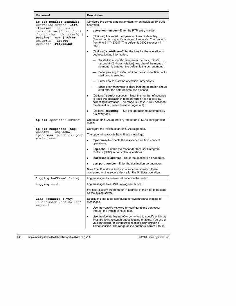
230 Implementing Cisco Switched Networks (SWITCH) v1.0 2009 Cisco Systems, Inc. ©
Command Description
ip sla monitor schedule oper{for[sta[monpendhh:mseco
Configure the scheduling parameters for an individual IP SLAs
tion the RTR entry number.
Optionaeg
—
nth.
—
— Ente
—
(Optional) ageout seconds—Enter the number of seconds to kcollecthe defa
(Optionarun ev
ation-number [life ever | seconds}] rt-time {hh:mm [:ss] th day | day month] | ing | now | after m:ss] [ageout nds] [recurring]
operation.
opera
(Optiona(forever) ofrom 0 to hour).
(b
-number—Enter
l) life —Set the operation to run indefinitely r for a specific number of seconds. The range is
2147483647. The default is 3600 seconds (1
l) start-time—Enter the time for the operation to in collecting information:
To start at a specific time, enter the hour, minute, second (in 24-hour notation), and day of the month. If no month is entered, the default is the current mo
Enter pending to select no information collection until a start time is selected.
r now to start the operation immediately.
Enter after hh:mm:ss to show that the operation should start after the entered time has elapsed.
eep the operation in memory when it is not actively ting information. The range is 0 to 2073600 seconds,
ult is 0 seconds (never ages out).
l) recurring — Set the operation to automatically ery day.
ip sla operation-number Create an mode.
IP SLAs operation, and enter IP SLAs configuration
ip sla responder {tcp-connect | udp-echo} ipaddress ip-address port port-number
Configure t
The optiona
tcp-con r for TCP connect ions
choProtocol (U or jitter operations.
ddress
Nconfigured
he switch as an IP SLAs responder.
l keywords have these meanings:
nect—Enable the respondeoperat
udp-e
.
—Enable the responder for User Datagram DP) echo
ipa
port port-
ote The IP ad
ip-address—Enter the destination IP address.
number—Enter the destination port number.
dress and port number must match those on the source device for the IP SLAs operation.
logging buffered [size] Log mes he switch. sages to an internal buffer on t
logging host Log mes
For hostas
sages to a UNIX syslog server host.
, specify the name or IP address of the host to be used the syslog server.
line [console | vty] line-number [ending-line-number]
Spec fme
Use the cothrough th
e linre t
vty c nnecTelnet ses
i y the line to be configured for synchronous logging of ssages.
nsole keyword for configurations that occur e switch console port.
Use thlines a
o
e vty line-number command to specify which vty o have synchronous logging enabled. You use a tion for configurations that occur through a sion. The range of line numbers is from 0 to 15.

© 2009 Cisco Systems, Inc. Lab Guide 231
Command Description
logging synchronous [leveall] buffe
Enable synchronous logging of messages.
lesse
(Optionaprint
p
messThe default is
l [severity-level | | limit number-of-rs]
(Optionalseverity lehighenumbers
) For level severity-level, specify the message vel. Messages with a severity level equal to or
r than this value are printed asynchronously. Low mean greater severity and high numbers mean
r severity. The default is 2.
l) Specifying level all means that all messages are ed asynchronously regardless of the severity level.
(O tional) For limit number-of-buffers, specify the number of buffers to be queued for the terminal after which new
ages are dropped. The range is 0 to 2147483647. 20.
no logging console Disable message logging.
show ip sla responder Verify the IP SLAs responder configuration on the device.
show splays information about the IP SLA tests. ip sla statistics Di
show [oper
ptional) Displa all defaults for As oper
ip sla configuration (Oation-number] all IP SL
y configuration values, including ations or a specified operation.
show NMP statistics. snmp Displays S
snmp-strin[ro |numbe
the co
one or more community strings of any length.
(Optional) F ccessible to commu
stationscommunit
acce 1300 to 1999.
server community Configure g [view view-name] rw] [access-list-r]
For string, spermits acc
mmunity string.
pecify a string that acts like a password and ess to the SNMP protocol. You can configure
or view, specify the view record athe
(Optionauthorizspecif
nity.
al) Specify either read-only (ro) if you want ed management stations to retrieve MIB objects, or
y read-write (rw) if you want authorized management to retrieve and modify MIB objects. By default, the
y string permits read-only access to all objects.
(Optional) For access-list-number, enter an IP standard ss list numbered from 1 to 99 and
snmp-server engineID {local engineid-string | remote ip-address [udp-port port-number] engineid-string}
Conf
The engnam24-cthe portiozeroengine I
If youat contain
g
igure a name for either the local or remote copy of SNMP.
ineid-string is a 24-character ID string with the e of the copy of SNMP. You need not specify the entire haracter engine ID if it has trailing zeros. Specify only
n of the engine ID up to the point where only s remain in the value. For example, to configure an
D of 123400000000000000000000, you can enter this: snmp-server engineID local 1234.
select remote, specify the ip-address of the device thUser DataThe defau
s the remote copy of SNMP and the optional ram Protocol (UDP) port on the remote device.
lt is 162.
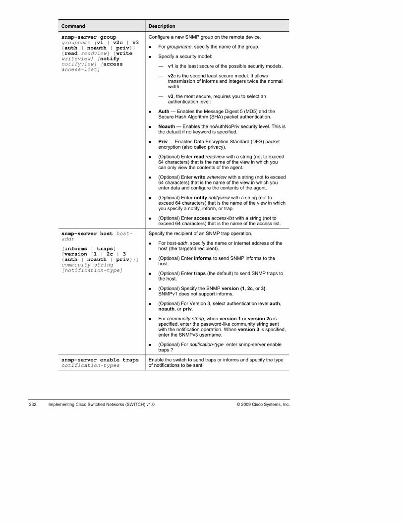
232 Implementing Cisco Switched Networks (SWITCH) v1.0 © 2009 Cisco Systems, Inc.
Command Description
snmp-server group grou{aut[reawritnotiacce
Configure a new SNMP group on the remote device.
p
models.
—
width.
— authent
Auth — Enables the Message Digest 5 (MD5) and the Sec
Noauth — Enables vel. This is the defa
Priencr
64 ccan on
O64 cnt
(Optionaexcyou
exc
pname {v1 | v2c | v3 h | noauth | priv}} d readview] [write eview] [notify fyview] [access ss-list]
For grou
Specify a s
— v1
name, specify the name of the group.
ecurity model:
is the least secure of the possible security
v2c is the second least secure model. It allows transmission of informs and integers twice the normal
v3, the most secure, requires you to select an ication level:
ure Hash Algorithm (SHA) packet authentication.
the noAuthNoPriv security leult if no keyword is specified.
v — Enables Data Encryption Standard (DES) packet yption (also called privacy).
(Optional) Enter read readview with a string (not to exceed haracters) that is the name of the view in which you
ly view the contents of the agent.
( ptional) Enter write writeview with a string (not to exceed haracters) that is the name of the view in which you
e er data and configure the contents of the agent.
l) Enter notify notifyview with a string (not to eed 64 characters) that is the name of the view in which specify a notify, inform, or trap.
(Optional) Enter access access-list with a string (not to eed 64 characters) that is the name of the access list.
snmp-server host host-addr
[informs | traps] [version {1 | 2c | 3 {auth | noauth | priv}}] community-string [notification-type]
Specify the rec
hos
(Optiona
(Optionathe hos
ptional)SN
(Optiona uth,
ord-like community string sent with
(Optiona e enter snmp-server enable rap
ipient of an SNMP trap operation.
For host-addr, specify the name or Internet address of the t (the targeted recipient).
l) Enter informs to send SNMP informs to the host.
l) Enter traps (the default) to send SNMP traps to t.
(O Specify the SNMP version (1, 2c, or 3). MPv1 does not support informs.
l) For Version 3, select authentication level a, or priv.
noauth
For comspecifie
munity-string, when version 1 or version 2c is d, enter the passw
the notification operation. When version 3 is specified, enter the SNMPv3 username.
l) For notification-typt s ?
snmp-server enable traps notification-types
Enable of notifications to be sent.
the switch to send traps or informs and specify the type
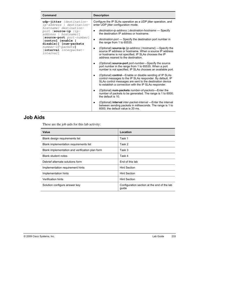
© 2009 Cisco Systems, Inc. Lab Guide 233
Command Description
udp-jitter {destination-ip-adhostnport addre[sour[contdisabnumbe[inteinter
Configure the IP SLAs operation as a UDP jitter operation, and tter
n-destination IP address or hostname.
s
ddress
tiport numbnum
(Optiona
SLAsto es
p
the defa
(Optionabetw
0
dress | destination-ame} destination-[source-ip {ip-ss | hostname}] ce-port port-number] rol {enable | le}] [num-packets r-of-packets] rval interpacket-val]
enter UDP ji
destinatiothe
dethe range from 1 t
(Optional) soursourcor hosaddres
(Op
configuration mode.
ip-address | destination-hostname — Specify
tination-port — Specify the destination port number in o 65535.
ce-ip {ip-address | hostname} —Specify the e IP address or hostname. When a source IP atname is not specified, IP SLAs chooses the IP s nearest to the destination.
onal) source-port port-number—Specify the source er in the range from 1 to 65535. When a port
ber is not specified, IP SLAs chooses an available port.
l) control—Enable or disable sending of IP SLAs control messages to the IP SLAs responder. By default, IP
control messages are sent to the destination device tablish a connection with the IP SLAs responder.
(O tional) num-packets number-of-packets—Enter the number of packets to be generated. The range is 1 to 6000;
ult is 10.
l) interval inter-packet-interval —Enter the interval een sending packets in milliseconds. The range is 1 to
60 0; the default value is 20 ms.
Job Aids These are the job aids for this lab activity:
Value Location
Blank design requirements list Task 1
Blank implementation requirements list Task 2
Blank i 3 mplementation and verification plan form Task
Blank student notes Task 4
Debrie olutions form End of this lab f alternate s
Implem Hint Section entation requirement hints
Implem Hint Section entation hints
Verifica Hint Section tion hints
Solutio uration section of the lab guide
n configure answer key Config at the end

234 Implementing Cisco Switched Networks (SWITCH) v1.0 © 2009 Cisco Systems, Inc.
TA
et, your first task is to create a list where you will documlab vimpleat the
ask 1: Create an Implementation Requirement List for High vailability and Reporting
After you have analyzed the Information Packent the requirements for a successful implementation. Use the following table, the initial
isual objective, and the implementation policy and devices information to create your mentation requirement list. If you are unsure, you can use the hints information provided end of the lab guide.
Device High Level Task Information Source

© 2009 Cisco Systems, Inc. Lab Guide 235
Ta
on eacbecausorder. you wimplemthe Imat the
sk 2: Create an Implementation and Verification Plan The next step in your configuration deployment is to create a task list of each item to configure
h device and in what order. The Implementation and Verification Plan is very important, e it enables you to ensure that all requirements are properly configured and in the correct The task will help you setup configuration checkpoints. Use the plan to determine how ill verify that each required item was effectively configured. You will move to the actual
entation in the next task. Use the following table and the Information Packet to create plementation and Verification Plan. If you are unsure, use the hints information provided end of this lab.
Complete √
Device Implemen-tation order
Values and items to implement
Verification method and expected results

236 Implementing Cisco Switched Networks (SWITCH) v1.0 © 2009 Cisco Systems, Inc.
Tplanned the implementation, you are ready
to cosolutspeciyour verifi
ask 3: Implement and Verify Now that you have all of the requirements and have
nnect to the remote lab and implement your solution. Do not forget to save! Once your ion is implemented, verify your configuration is working and fulfills the requirements fied. Use the previous table to document the verifications you conducted to ensure that solution is complete. Hints are available at the end of this lab if you are unsure about the cation steps.

© 2009 Cisco Systems, Inc. Lab Guide 237
Ste to document the details that you think are important to remember.
____
______
______
__________
__________________________________________________________________________
__________
______
______
______
__________________________________________________________________________
__________________________________________________________________________
______
______
______
__________
__________________________________________________________________________
__________
______
______
______
__________________________________________________________________________
__________________________________________________________________________
______
______
______
__________
udent Notes Use the following spac
______________________________________________________________________
____________________________________________________________________
____________________________________________________________________
________________________________________________________________
________________________________________________________________
____________________________________________________________________
____________________________________________________________________
____________________________________________________________________
____________________________________________________________________
____________________________________________________________________
____________________________________________________________________
________________________________________________________________
________________________________________________________________
____________________________________________________________________
____________________________________________________________________
____________________________________________________________________
____________________________________________________________________
____________________________________________________________________
____________________________________________________________________
________________________________________________________________

238 Implementing Cisco Switched Networks (SWITCH) v1.0 © 2009 Cisco Systems, Inc.
_____
__________________________________________________________________________
_____
_____
_____
_____
__________________________________________________________________________
__________________________________________________________________________
_____
_____
_____
_____
__________________________________________________________________________
_____
_____
_____
_____
__________________________________________________________________________
__________________________________________________________________________
_____
_____
_____
_____
__________________________________________________________________________
_____
_____
_____________________________________________________________________
_____________________________________________________________________
_____________________________________________________________________
_____________________________________________________________________
_____________________________________________________________________
_____________________________________________________________________
_____________________________________________________________________
_____________________________________________________________________
_____________________________________________________________________
_____________________________________________________________________
_____________________________________________________________________
_____________________________________________________________________
_____________________________________________________________________
_____________________________________________________________________
_____________________________________________________________________
_____________________________________________________________________
_____________________________________________________________________
_____________________________________________________________________
_____________________________________________________________________

© 2009 Cisco Systems, Inc. Lab Guide 239
Al
duringother p
_____ ________________________________________
______
______
__________________________________________________________________________
__________________________________________________________________________
______
______
______
__________
__________________________________________________________________________
__________
______
______
______
__________________________________________________________________________
__________________________________________________________________________
______
______
______
__________
__________________________________________________________________________
__________
______
______
______
ternate Resources and Solutions to the One You Used Other groups may use a solution different from yours. Possible solutions will be discussed
the debrief period after the lab. For your reference, use the following space to document ossible solutions.
_____________________________
____________________________________________________________________
____________________________________________________________________
____________________________________________________________________
____________________________________________________________________
____________________________________________________________________
________________________________________________________________
________________________________________________________________
____________________________________________________________________
____________________________________________________________________
____________________________________________________________________
____________________________________________________________________
____________________________________________________________________
____________________________________________________________________
________________________________________________________________
________________________________________________________________
____________________________________________________________________
____________________________________________________________________
____________________________________________________________________

240 Implementing Cisco Switched Networks (SWITCH) v1.0 © 2009 Cisco Systems, Inc.
_____
__________________________________________________________________________
_____
_____
_____
_____
__________________________________________________________________________
__________________________________________________________________________
_____
_____
_____
_____
__________________________________________________________________________
_____
_____
_____
_____
__________________________________________________________________________
__________________________________________________________________________
_____
_____
_____
_____
__________________________________________________________________________
_____
_____________________________________________________________________
_____________________________________________________________________
_____________________________________________________________________
_____________________________________________________________________
_____________________________________________________________________
_____________________________________________________________________
_____________________________________________________________________
_____________________________________________________________________
_____________________________________________________________________
_____________________________________________________________________
_____________________________________________________________________
_____________________________________________________________________
_____________________________________________________________________
_____________________________________________________________________
_____________________________________________________________________
_____________________________________________________________________
_____________________________________________________________________
_____________________________________________________________________

© 2009 Cisco Systems, Inc. Lab Guide 241
La_____________
______
______
______
__________
__________________________________________________________________________
__________
______
______
______
__________________________________________________________________________
__________________________________________________________________________
______
______
______
__________
__________________________________________________________________________
__________
______
______
______
__________________________________________________________________________
__________________________________________________________________________
______
______
______
__________
b 5-1: Key Commands and Tools Used _____________________________________________________________
____________________________________________________________________
____________________________________________________________________
____________________________________________________________________
________________________________________________________________
________________________________________________________________
____________________________________________________________________
____________________________________________________________________
____________________________________________________________________
____________________________________________________________________
____________________________________________________________________
____________________________________________________________________
________________________________________________________________
________________________________________________________________
____________________________________________________________________
____________________________________________________________________
____________________________________________________________________
____________________________________________________________________
____________________________________________________________________
____________________________________________________________________
________________________________________________________________

242 Implementing d NetwCisco Switche orks (SWITCH) v1.0 © 2009 Cisco Systems, Inc.
Hu are encouraged to complete the labs using your knowledge. If you need a tip, this section
conta
Lab 5-1 Hint Sh
Imur network, the first task asks you to create an
The list details the elements needed to develop an imple
ints Yo
ins a series of hints to help you complete the lab.
eet: Implementing HA in a Network Design
plementation Requirements To facilitate the configuration of yoImplementation Requirements list.
mentation plan. The following is an example of such a list:
Device Implementation Requirement Hint
All s witches and routers Syslog server Implementation policy section
All sw routers SNMP policy section itches and Implementation
ASW1 and CSW1 IP SLA Implementation policy section
ASW2 and CSW2 IP SLA Implementation policy section
All sw Implementation policitches and routers Verification y section
Device High Level Task Information Source
ASW1 Design and Implementa Syslog server Network Diagram, tion Requirements
ASW SNMP Network Diagram, Design and Implementation Requirements 1
ASW1 IP SLA Network Diagram, Design and Implementation Requirements
ASW2 Syslog server Network Diagra ion Requirements m, Design and Implementat
ASW2 SNMP Network Diagram, Design and Implementation Requirements
ASW2 IP SLA Network Diagram, Design and Implementation Requirements
DSW1 yslog se Network Diagram, S rver Design and Implementation Requirements
DSW1 MP Network Diagra SN m, Design and Implementation Requirements
DSW2 Syslog server Network Diagram, Design and Implementation Requirements
DSW2 SNMP Network Diagram, Design and Implementation Requirements
CSW1 yslog se Network Diagram, S rver Design and Implementation Requirements
CSW1 MP Network Diagram, SN Design and Implementation Requirements
CSW1 SLA Network Diagra IP m, Design and Implementation Requirements
CSW2 Syslog server Network Diagram, Design and Implementation Requirements
CSW2 SNMP Network Diagram, Design and Implementation Requirements
CSW2 IP SLA Network Diagram, Design and Implementation Requirements
R1 yslog se Network Diagram, S rver Design and Implementation Requirements
R1 NMP Network DiagraS m, Design and Implementation Requirements
R2 Syslog server Network Diagram, Design and Implementation Requirements
R2 SNMP Network Diagram, Design and Implementation Requirements

© 2009 Cisco Systems, Inc. Lab Guide 243
Imptation and Verification Plan. There are several
possibin a tewith itPlan fo
lementation and Verification Plan In the next task, you will create an Implemen
le correct solutions. One possible approach groups items that are common to all switches mplate and then applies the template to all switches. You can then configure each switch ems that are unique to each device. An example of the Implementation and Verification llows.

244 Implementing co Switched Ne ITC .0 Cisco SCis tworks (SW H) v1 © 2009 ystems, Inc.
Complete √
Device Implementation order
Values and items to implement
Verification method and expected results
ASW1 1 Logging on w logging. Sho
ASW1 Logging 10.1.3. w logging. 2 50 Sho
ASW1 Logging traps informational
3 Show logging.
ASW2 4 Logging on Show logging.
ASW2 5 Logging 10.1.4.100 Show logging
ASW2 6 Logging traps informational
Show logging.
DSW1 Logging on 7 Show logging.
DSW1 Logging 10.1.3. ogging. 8 50 Show l
DSW1 Logging traps informational
w logging. 9 Sho
DSW2 10 Logging on Show logging.
DSW2 11 Logging 10.1.4.100 Show logging.
DSW2 12 Logging traps informational
Show logging.
CSW1 Logging on w logging. 13 Sho
CSW1 Logging 10.1.3. . 14 50 Show logging
CSW1 Logging traps informational
ogging. 15 Show l
CSW2 16 Logging on Show logging.
CSW2 17 Logging 10.1.4.100 Show logging.
CSW2 18 Logging traps informational
Show logging.
ASW1 snmp-server entraps errdisable
snmp. 19 able Show
ASW1 snmp-server entraps config
w snmp. 20 able Sho
ASW1 snmp-server enabtraps vlan-mem
21 le Show snmp. bership
ASW1 23 snmp-server cociscor ro
snmp. mmunity Show
ASW1 snmp-server ho24 st 10.1.3.50 traps ciscor
Show snmp.
ASW2 25 snmp-server enable traps errdisable
Show snmp.
ASW2 26 snmp-server enable traps config
Show snmp.
ASW2 27 snmp-server enable traps vlan-membership
Show snmp..
ASW2 28 snmp-server community ciscor ro
Show snmp.
Comment [A3]: Is this referring to The CiscoR 12000 Series Eight-Port OC-48c/STM-16c POS Line Card (8-Port OC-48 POS) or anything related? There are several instances of ciscor and ciscor ro in this table. Please verify okay or correct.

© 2009 Cisco Systems, Inc. Lab Guide 245
Complete √
Device Implementation order
Values and items to implement
Verification method and expected results
ASW2 29 snmp-server host 10.1.4.100 traps ciscor
Show snmp.
DSW1 30 snmp-server enatraps errdisable
ble Show snmp.
DSW1 snmp-server enatraps config
31 ble Show snmp.
DSW1 32 snmp-server enatraps vlan-memb
ble ership
Show snmp.
DSW1 33 snmp-server comciscor ro
munity Show snmp.
DSW1 34 snmp-server hos10.1.3.50 traps ci
t Show snmp. scor
DSW2 35 snmp-server enable traps errdisable
Show snmp.
DSW2 36 snmp-server enable traps config
Show snmp.
DSW2 37 snmp-server enable traps vlan-membership
Show snmp.
DSW2 38 snmp-server community ciscor ro
Show snmp.
DSW2 39 snmp-server host 10.1.4.100 traps ciscor
Show snmp.
CSW1 40 snmp-server enatraps errdisable
ble Show snmp.
CSW1 snmp-server enable traps config
41 Show snmp.
CSW1 snmp-server enatraps vlan-memb
42 ble ership
Show snmp.
CSW1 43 snmp-server comciscor ro
munity Show snmp.
CSW1 44 snmp-server host 10.1.3.50 traps ciscor
Show snmp.
CSW2 45 snmp-server enable traps errdisable
Show snmp.
CSW2 46 snmp-server enable traps config
Show snmp.
CSW2 47 snmp-server enable traps vlan-membership
Show snmp.
CSW2 48 snmp-server community ciscor ro
Show snmp.
CSW2 49 snmp-server host 10.1.4.100 traps ciscor
Show snmp.
R1 50 snmp-server enable traps config
Show snmp.
R1 51 snmp-server comciscor ro
snmp. munity Show
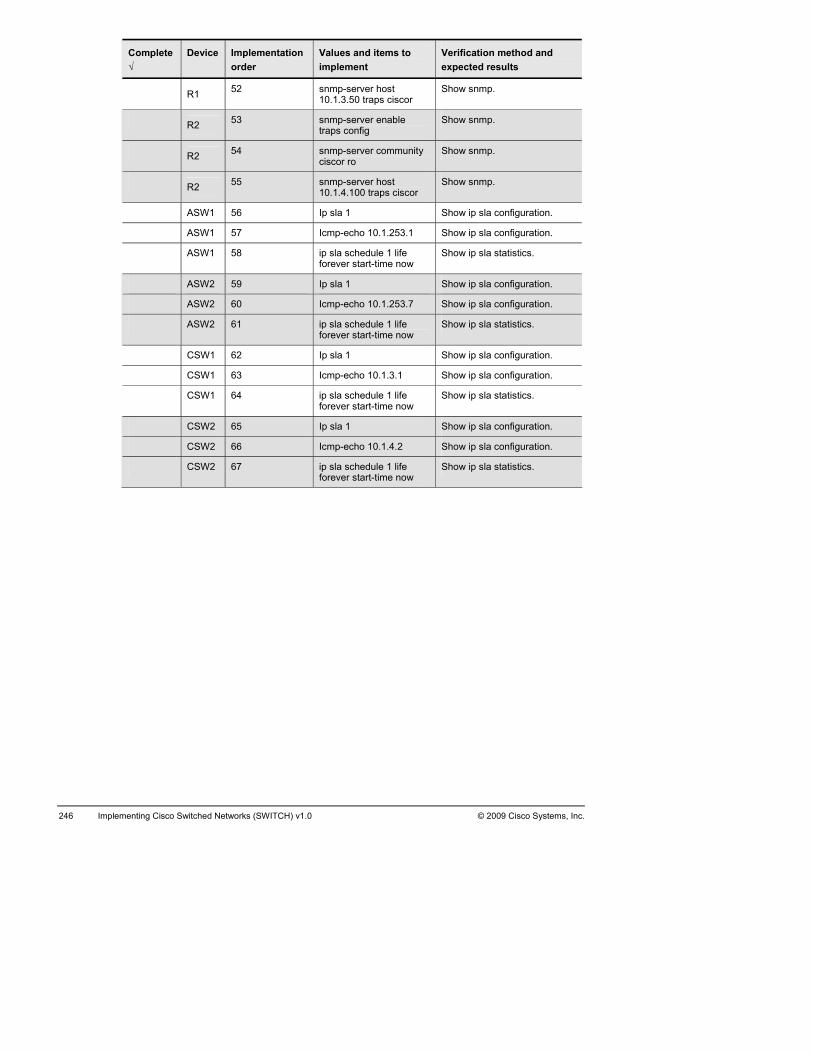
246 Implementing Cisco Switched Networks (SWITCH) v1.0 © 2009 Cisco Systems, Inc.
Complete √
Device Implementation order
Values and items to implement
Verification method and expected results
R1 52 snmp-server host 10.1.3.50 traps c
Show snmp. iscor
R2 53 snmp-server enable traps config
Show snmp.
R2 54 snmp-server community ciscor ro
Show snmp.
R2 55 snmp-server host 10.1.4.100 traps ciscor
Show snmp.
ASW1 56 Ip sla 1 a configurationShow ip sl .
ASW1 Icmp-echo 10.1 uration57 .253.1 Show ip sla config .
ASW1 ip sla schedule forever start-tim
Show ip sla statistics. 58 1 life e now
ASW2 59 Ip sla 1 Show ip sla configuration.
ASW2 60 Icmp-echo 10.1.253.7 Show ip sla configuration.
ASW2 61 ip sla schedule 1 life forever start-time now
Show ip sla statistics.
CSW1 Ip sla 1 Show ip sla configurat62 ion.
CSW1 Icmp-echo 10.1 igurat63 .3.1 Show ip sla conf ion.
CSW1 ip sla schedule forever start-tim
tistics. 64 1 life e now
Show ip sla sta
CSW2 65 Ip sla 1 Show ip sla configuration.
CSW2 66 Icmp-echo 10.1.4.2 Show ip sla configuration.
CSW2 67 ip sla schedule 1 life forever start-time now
Show ip sla statistics.

© 2009 Cisco Systems, I 247 nc. Lab Guide
Step-Ste face in configuration mode
Step 2 Confi
Step 3 Repeat ste W2, CSW1, CSW2,and routers R1 and R2. Verify sys
DSW1#
No In C M tor logging: level debugging, 0 messages logged, xml disabled, filtering disabled B er logging: level debugging, 1022 messages logged, xml disabled, E C t and timestamp logging messages: disabled F P T
Step 4 Configure
ASW1(ASW1( ASW1(ASW1(ASW1(
by-Step Procedure p 1 Connect to ASW1 switch inter
Connect to the remote lab.
Access the Switch console.
Enter privilege mode, using enable.
Enter configuration mode, using configure terminal.
gure Syslog server on switch ASW1:
ASW1(config)# logging on ASW1(config)# logging 10.1.3.50 ASW1(config)# logging trap informational
ps 1 and 2 on switches ASW2, DSW1, DSlog server configuration, for example on DSW1:
show logging Syslog logging: enabled (0 messages dropped, 0 messages rate-limited, 0 flushes, 0 overruns, xml disabled, filtering disabled) No Active Message Discriminator.
active Message Discriminator.
onsole logging: disabled oni uff filtering disabled eption Logging: size (4096 bytes) xc
ounile logging: disabled ersistent logging: disabled rap logging: level informational, 1000 message lines logged
abled, Logging to 10.1.3.51 (udp port 514, audit dis authentication disabled, encryption disabled, link up), 150 message lines logged, 0 message lines rate-limited, 0 message lines dropped-by-MD, xml disabled, sequence number disabled filtering disabled
SNMP on switch ASW1:
config)# snmp-server community ciscor ro config)# snmp-server host 10.1.3.50 traps ciscor
config)# snmp-server enable traps errdisable config)# snmp-server enable traps config config)# snmp-server enable traps vlan-membership

248 Implementing Cisco Switched Networks (SWITCH) v1.0 © 2009 Cisco Systems, Inc.
Step 5 Repeat step 4 on switches ASW2, DSW1, DSW2, CSW1, and CSW2. On routers R1 and R2, repeat step 4 without errdisable and without vlan-membership. Verify the snmp configuration, for example on CSW1:
CSW1#show snmp Chas0 SN supplied ize 1000) 5 SN t size 1500) SNMP SNMP /10, 5 sent, 0 dropped. SNMP
Step 6 Configur
ASW1ASW1 .1.253.1 ASW1
Step 7 Repeat st
Roun Late ar 5 1993 Late
Operat
sis: FDO1310X136 MP packets input 0 Bad SNMP version errors 0 Unknown community name 0 Illegal operation for community name0 Encoding errors 0 Number of requested variables 0 Number of altered variables 0 Get-request PDUs 0 Get-next PDUs 0 Set-request PDUs
aximum queue s0 Input queue packet drops (MMP packets output
packe0 Too big errors (Maximum 0 No such name errors 0 Bad values errors 0 General errors 0 Response PDUs 5 Trap PDUs global trap: disabled
logging: enabled Logging to 10.1.3.51.162, 0 agent enabled
e IP SLA on switch ASW1:
onfig)# ip sla 1 (c(config-ip-sla)#icmp-echo 10(config)# ip sla schedule 1 life forever start-time now
2, and CSW2. Verify that the IP SLA test is running:ep 6 on switches CSW1, ASW
CSW1#show ip sla statistics
d Trip Time (RTT) for Index 1 Latest RTT: 1 ms
st operation start time: *22:24:34.231 eastern Fri Mst operation return code: OK er of successes: 290 Numb
Number of failures: 0 ion time to live: Forever

© 2009 Cisco Systems, Inc. Lab Guide 249
Laigh
Availa
Activity Objr your company has become a friend of yours. Once, while
m and an engineer from Cisco, the engineer mentioned the need for a nwant texistendiscusyou tofeatureand pelab to object
De
Cr
Cr
b 6-1: Implement and Tune HSRP Complete this lab activity to confirm your knowledge from the course on the topics of H
bility and Reporting.
ective The Cisco account manager fohaving a friendly chat with hi
etwork to have a redundancy mechanism implemented. You like the idea as you do not o take unnecessary risks. You dig deep into the documentation and find out about the ce of a protocol called Hot Standby Router Protocol (HSRP). After an informal
sion with your IT manager, he gives a green light to proceed with the project, but asks demonstrate HSRP step by step, to understand how it really works and what the various s are. As you leave him, you realize the need to create a design, implementation plan, rform the reconfiguration. Once the design is complete, you will connect to your remote implement your solution. After completing this activity, you will be able to meet these ives:
sign a HSRP solution.
eate an implementation requirements list.
eate a step-by-step implementation and verification plan.
Implement and verify your solution.

250 Implementing Cisco Switched Networks (SWITCH) v1.0 © 2009 Cisco Systems, Inc.
Ination needed to accomplish in this activity. Read it carefully.
The Ialong
ImplementatioRP in your network. The following lists details preparation and s for all switches in the company network. Your configuration must
imple
YC
For both cases, switches DSW1 and DSW2 will be the default gateways for the clients.
e interfaces will decrement the priority of switch DSW1 by 30.
e interfaces will decrement the priority of switch DSW1 by 30.
In your implementation, proceed in order:
, implement the preempt feature. Test.
riority.
formation Packet This packet contains the inform
nformation Packet describes the requirements common to all devices in the network, with information specific to each device.
n Policy You have to configure HSconfiguration requirement
ment all these requirements:
ou must implement two HSRP solutions: one offering first hop redundancy for client LT1 in VLAN 3, and one offering first hop redundancy for client CLT2 in VLAN 4.
Switch DSW1 will be the primary HSRP router on VLAN3 and secondary HSRP router on VLAN4.
Switch DSW2 will be the primary HSRP router on VLAN4 and secondary HSRP router on VLAN3.
Primary HSRP on switch DSW1 will track interfaces Po31 and Po32. The loss of connectivity to thes
Primary HSRP on switch DSW2 will track interfaces Po31 and Po32. The loss of connectivity to thes
Preempt should be configured so that each Layer 3 switch tries to become primary whenever possible.
— Start by implementing HSRP in both VLANs, without preempt, without tracking, and without priority. Test by shutting down the link to the primary HSRP router, then reenabling the link.
— Once this has been tested
— Once you have tested this, implement tracking and p

Devmation about IP addresses:
ices Information The table provides infor
© 2009 Cisco Systems, Inc. Lab Guide 251
Device name HSRP IP address IP address HSRP IP address VLAN 3 VLAN 4
ASW1 No - - -
ASW2 No - - -
DSW1 Yes 10.1.3. 10.1.4.3 3 10.1.3.1
DSW2 Yes 10 10.1.4.2 .1.4.1 .1.3.2 10
CSW1 No - - -
CSW2 No - - -
R1 No - - -
R2 No - - -
Network Diagram
© 2009
Vi Objecti for Lab 6-1: Impl ment and RP
sual ve eTune HS
Cisco Systems, Inc. All rights reserved. SWITCH v1.0—49

252 Implementing Cisco Switched Networks (SWITCH) v1.0 © 2009 Cisco Systems, Inc.
Ce commands that are used in this activity.
ommand List The table describes th
Command Description
conf inal Enters global c from privileged EXEC mode, igure term onfiguration mode
inte nters interfacterface on wh
rface interface-id Ein
e configuration mode, and enter the Layer 3 ich you want to enable HSRP.
stan ) Conf
1— Select
lect
dby version {1 | 2} (Optional igures the HSRP version on the interface.
HSRPv1.
2— Se HSRPv2.
standby [ ] ip [ip-address [secondary]]
umber and vir
number on the
mber.
musinte
(Optionahot
the primaraddrstandby
group-number Creates (or enables) the HSRP group using its ntual IP address.
(Optional) group-number — The groupinterface for whto 255; the you do no
(Optiona
ich HSRP is being enabled. The range is 0 default is 0. If there is only one HSRP group,
t need to enter a group nu
l on all but one interface) ip-address — The virtual IP address of the hot standby router interface. You
t enter the virtual IP address for at least one of the rfaces; it can be learned on the other interfaces.
l) secondary — The IP address is a secondary standby router interface. If neither router is designated
as a secondary or standby router and no priorities are set, y IP addresses are compared and the higher IP
ess is the active router, with the next highest as the router.
standby [group-number] priority priority [preempt [delay delay]]
Sets a priorangrepresen
(Optionawhic
(Optionarouter ctive router, it
mes c
nal)ne t
onds fault is 0 no de
rity value used in choosing the active router. The e is 1 to 255; the default priority is 100. The highest number
ts the highest priority.
l) group-number — The group number to h the command applies.
l) preempt — Select so that when the local has a higher priority than the a
assu
(Optiopostpoof sec
ontrol as the active router.
delay — Set to cause the local router to aking over the active role for the shown number . The range is 0 to 3600(1 hour); the de
( lay before taking over).
standby [group-number] track type number [interface-priority]
Configures e of the otherpriorit
(Optionawhic
numb
numbeinte
ional)hich t
remenr comes is 10.
an interface to track other interfaces so that if on interfaces goes down, the device's Hot Standby
y is lowered.
l) group-number — The group number to h the command applies.
type — Enter the interface type (combined with interface er) that is tracked.
r — Enter the interface number (combined with rface type) that is tracked.
(Optby wdeco
interface-priority — Enter the amount he hot standby priority for the router is ted or incremented when the interface goes down back up. The default value
show standby [interface-id [group]]
Verify the configuration.

© 2009 Cisco Systems, Inc. Lab Guide 253
Johe job aids for this lab activity:
b Aids These are t
Value Location
Blank d uirements list Task 1 esign req
Blank im Task 2 plementation requirements list
Blank implem Task 3 entation and verification plan form
Blank st Task 4 udent notes
Debrief End of this lab alternate solutions form
Implem Hint Section entation requirement hints
Implem Hint Section entation hints
Verification hi Hint Section nts
Solution c Configuration section at tend of the lab guide
onfigure answer key he

254 Implementing Cisco Switched Networks (SWITCH) v1.0 © 2009 Cisco Systems, Inc.
TC
zed the Information Packet, your first task is to create a list where you will documlab vimpleat the
ask 1: Create an Implementation Requirement List for HSRP onfiguration
After you have analyent the requirements for a successful implementation. Use the following table, the initial
isual objective, and the implementation policy and devices information to create your mentation requirement list. If you are unsure, you can use the hints information provided end of the lab guide.
Device High Level Task Information Source

© 2009 Cisco Systems, I Lab G de 255 nc. ui
Ta
on eacbecausorder. you wimplemthe Imat the
sk 2: Create an Implementation and Verification Plan The next step in your configuration deployment is to create a task list of each item to configure
h device and in what order. The Implementation and Verification Plan is very important, e it enables you to ensure that all requirements are properly configured and in the correct The task will help you setup configuration checkpoints. Use the plan to determine how ill verify that each required item was effectively configured. You will move to the actual
entation in the next task. Use the following table and the Information Packet to create plementation and Verification Plan. If you are unsure, use the hints information provided end of this lab.
Complete √
Device Implemen-tation order
Values and items to implement
Verification method and expected results

256 Implementing Cisco Switched Networks (SWITCH) v1.0 © 2009 Cisco Systems, Inc.
Complete √
Device Implemen-tation order
Values and items to implement
Verification method and expected results

© 2009 Cisco Systems, Inc. Lab Guide 257
Talanned the implementation, you are ready
to con
Duringorder:
Stwithout priority. Test by shutting down the link to the primary HSRP router, then re-
acking and priority.
req ed to re unsure
about the verification steps.
sk 3: Implement and Verify Now that you have all of the requirements and have p
nect to the remote lab and implement your solution. Do not forget to save!
your implementation, do not forget to follow the Information Packet implementation
art by implementing HSRP in both VLANs, without preempt, without tracking, and
enabling the link.
Once you have tested this, implement the preempt feature. Test.
Once you have tested this, implement tr
Once your solution is implemented, verify your configuration is working and fulfills the uirements specified. Use the previous table to document the verifications you conduct
ensure that your solution is complete. Hints are available at the end of this lab if you a

258 Implementing Cisco Switched Networks (SWITCH) v1.0 © 2009 Cisco Systems, Inc.
Sce to document the details that you think are important to remember.
___
_____
_____
_____
__________________________________________________________________________
_____
_____
_____
_____
__________________________________________________________________________
__________________________________________________________________________
_____
_____
_____
_____
__________________________________________________________________________
_____
_____
_____
_____
__________________________________________________________________________
__________________________________________________________________________
_____
_____
_____
_____
tudent Notes Use the following spa
_______________________________________________________________________
_____________________________________________________________________
_____________________________________________________________________
_____________________________________________________________________
_____________________________________________________________________
_____________________________________________________________________
_____________________________________________________________________
_____________________________________________________________________
_____________________________________________________________________
_____________________________________________________________________
_____________________________________________________________________
_____________________________________________________________________
_____________________________________________________________________
_____________________________________________________________________
_____________________________________________________________________
_____________________________________________________________________
_____________________________________________________________________
_____________________________________________________________________
_____________________________________________________________________
_____________________________________________________________________

© 2009 Cisco Systems, Inc. Lab Guide 259
__________
__________________________________________________________________________
__________
______
______
______
__________________________________________________________________________
__________________________________________________________________________
______
______
______
__________
__________________________________________________________________________
__________
______
______
______
__________________________________________________________________________
__________________________________________________________________________
______
______
______
__________
__________________________________________________________________________
__________
______
________________________________________________________________
________________________________________________________________
____________________________________________________________________
____________________________________________________________________
____________________________________________________________________
____________________________________________________________________
____________________________________________________________________
____________________________________________________________________
________________________________________________________________
________________________________________________________________
____________________________________________________________________
____________________________________________________________________
____________________________________________________________________
____________________________________________________________________
____________________________________________________________________
____________________________________________________________________
________________________________________________________________
________________________________________________________________
____________________________________________________________________

260 Implementing Cisco Switched Networks (SWITCH) v1.0 © 2009 Cisco Systems, Inc.
A
durinother
____ _________________________________________
_____
_____
__________________________________________________________________________
__________________________________________________________________________
_____
_____
_____
_____
__________________________________________________________________________
_____
_____
_____
_____
__________________________________________________________________________
__________________________________________________________________________
_____
_____
_____
_____
__________________________________________________________________________
_____
_____
_____
_____
lternate Resources and Solutions to the One You Used Other groups may use a solution different from yours. Possible solutions will be discussed
g the debrief period after the lab. For your reference, use the following space to document possible solutions.
_____________________________
_____________________________________________________________________
_____________________________________________________________________
_____________________________________________________________________
_____________________________________________________________________
_____________________________________________________________________
_____________________________________________________________________
_____________________________________________________________________
_____________________________________________________________________
_____________________________________________________________________
_____________________________________________________________________
_____________________________________________________________________
_____________________________________________________________________
_____________________________________________________________________
_____________________________________________________________________
_____________________________________________________________________
_____________________________________________________________________
_____________________________________________________________________
_____________________________________________________________________

© 2009 Cisco Systems, Inc. Lab Guide 261
__________
__________________________________________________________________________
__________
______
______
______
__________________________________________________________________________
__________________________________________________________________________
______
______
______
__________
__________________________________________________________________________
__________
______
______
______
__________________________________________________________________________
__________________________________________________________________________
______
______
______
__________
__________________________________________________________________________
__________
________________________________________________________________
________________________________________________________________
____________________________________________________________________
____________________________________________________________________
____________________________________________________________________
____________________________________________________________________
____________________________________________________________________
____________________________________________________________________
________________________________________________________________
________________________________________________________________
____________________________________________________________________
____________________________________________________________________
____________________________________________________________________
____________________________________________________________________
____________________________________________________________________
____________________________________________________________________
________________________________________________________________
________________________________________________________________

262 Implementing Cisco Switched Networks (SWITCH) v1.0 © 2009 Cisco Systems, Inc.
L______________
_____
_____
_____
_____
__________________________________________________________________________
_____
_____
_____
_____
__________________________________________________________________________
__________________________________________________________________________
_____
_____
_____
_____
__________________________________________________________________________
_____
_____
_____
_____
__________________________________________________________________________
__________________________________________________________________________
_____
_____
_____
_____
ab 6-1: Key Commands and Tools Used ____________________________________________________________
_____________________________________________________________________
_____________________________________________________________________
_____________________________________________________________________
_____________________________________________________________________
_____________________________________________________________________
_____________________________________________________________________
_____________________________________________________________________
_____________________________________________________________________
_____________________________________________________________________
_____________________________________________________________________
_____________________________________________________________________
_____________________________________________________________________
_____________________________________________________________________
_____________________________________________________________________
_____________________________________________________________________
_____________________________________________________________________
_____________________________________________________________________
_____________________________________________________________________
_____________________________________________________________________
_____________________________________________________________________

© 2009 Cisco Systems, Inc. Lab Guide 263
Hiu are encouraged to complete the labs using your knowledge. If you need a tip, this section
contai
Lab 6-1 Hint Sheet: Imple
Implementation RTo facilitate the configuration of your network, the first task asks you to create an
list details the elements needed to develop an is an example of such a list:
nts Yo
ns a series of hints to help you complete the lab.
menting HA in a Network Design This solution provides the final configuration with preempt, priority, and tracking.
equirements
Implementation Requirements list. Theimplementation plan. The following
Device Implementation Requirement Hint
DSW1 HSRP Implementation policy section
DSW2 HSRP Implementation policy section
Device High Level Task Information Source
DSW1 on VLAN 4, primary on VLAN 3 and secondary on VLAN 4
Network Diagram, Design anImplementation Requirements
HSRP 3 and VLAN d
DSW2 HSRP on VLAN 3 and VLAN 4, primary on and secondary on VL
Network Diagram, Design and Implementation RequirVLAN 4 AN 3 ements

264 Implementing Cisco Switched Networks (SWITCH) v1.0 © 2009 Cisco Systems, Inc.
Imd Verification Plan. There are several possible
corretempthe fo
plementation and Verification plan In this task, you create an Implementation an
ct solutions. One possible approach groups items that are common to all switches in a late and then applies the template to all switches. For this lab, the template could contain llowing items:
Complete √
Device Implementation order
Values and items to implement
Verification method and expected results
3 DSW1 1 interface vlan
DSW1 2 ip 10.1.3.3 255.255.255.0
e vlan 3. address Show interfac
DSW1 standby 3 ip 10.13 .3.1
DSW1 standby 3 priorit4 y 120
DSW1 5 standby 3 preempt
DSW1 standby 3 track channel31 30
6 Port-
DSW1 standby 3 track Port-channel14 30
y. 7 Show standb
DSW1 interface vlan 4 8
DSW1 ip address 10.1.255.255.255.0
terface vlan 4. 9 4.3 Show in
DSW1 standby 4 ip 10.10 1.4.1
DSW1 standby 4 preempt y. 11 Show standb
DSW2 12 interface vlan 3
DSW2 standby 3 ip 10.13 1.3.1
DSW2 standby 3 preempt 14 Show standby.
DSW2 interface vlan 4 15
DSW2 standby 4 ip 10.16 1.4.1
DSW2 standby 4 priorit17 y 120
DSW2 standby 4 preem18 pt
DSW2 standby 4 track Port-channel31 30
19
DSW2 standby 4 track channel32 30
dby. 20 Port- Show stan
Step-by-Step Procedure Step 1 Connect to DSW1 switch interface in configuration m
Connect to the rem
Ac ess the Switch c
Enter privilege mo enable.
Enter configuratio figure terminal.
switch ode
ote lab.
c onsole.
de, using
n mode, using con

© 2009 Cisco Systems, Inc. Lab Guide 265
Step 2 Configure HSRP on VLAN3 on switch DSW1:
DSW1(config)# interface Vlan3 DSW1( 255.0 DSW1(DSW1(DSW1(DSW1(DSW1(
Step 3 Configure
DSW1(
DSW1(
Step 4 Repeat ste
Step 5 Configure
3.1
DSW2(DSW2(DSW2(DSW2(
Step 7 Verify HS n DSW1:
DSW1#Vlan6 Sta Vir Act
Pre Act Sta 2, priority 90 (expires in 11.200 sec) Pri T T GroVlan6 Sta Vir Act L .0c07.ac40 (v1 default) Hel N Pre Act Sta Pri Gro
config-if)# ip address 10.1.3.3 255.255.config-if)# standby 3 ip 10.1.3.1 config-if)# standby 3 priority 120 config-if)# standby 3 preempt config-if)# standby 3 track Port-channel31 30
0 config-if)# standby 3 track Port-channel32 3
HSRP on VLAN4 on switch DSW1:
config)# interface Vlan4 DSW1(config-if)# ip address 10.1.4.3 255.255.255.0DSW1(config-if)# standby 4 ip 10.1.4.1
config-if)# standby 4 preempt
p 1 on switch DSW2.
HSRP on VLAN3 on switch DSW2:
DSW2(config)# interface Vlan3 DSW2(config-if)# standby 3 ip 10.1.DSW2(config-if)# standby 3 preempt
Step 6 Configure HSRP on VLAN4 on switch DSW2:
config)# interface Vlan4 config-if)# standby 4 ip 10.1.4.1 config-if)# standby 4 priority 120 config-if)# standby 4 preempt
DSW2(config-if)# standby 4 track Port-channel31 30DSW2(config-if)# standby 4 track Port-channel32 30
RP configuration and priorities, for example o
show standby 3 - Group 63 te is Active tual IP address is 10.1.63.254 ive virtual MAC address is 0000.0c07.ac3f ocal virtual MAC address is 0000.0c07.ac3f (v1 default) L
Hello time 3 sec, hold time 10 sec Next hello sent in 1.664 secs
emption enabled ive router is local ndby router is 10.1.63.ority 120 (configured 120) rack interface Port-channel31 state Up decrement 30 rack interface Port-channel32 state Up decrement 30 up name is "hsrp-Vl63-63" (default) 4 - Group 64 te is Standby
54 000.0c07.ac40
tual IP address is 10.1.64.2ive virtual MAC address is 0ocal virtual MAC address is 0000lo time 3 sec, hold time 10 sec ext hello sent in 0.688 secs emption enabled ive router is 10.1.64.1, priority 120 (expires in 9.232 sec) ndby router is local ority 90 (configured 90)
4" (default) up name is "hsrp-Vl64-6

266 Implementing Cisco Switched Networks (SWITCH) v1.0 © 2009 Cisco Systems, Inc.
L on the topics of high
avail
Activity Objective igned and implemented a redundant network for its core layer. As u notice that the two routers in your aggregation layer are not in a
redunconna stanprepaa ver
D
C
C
Information Packet refully.
on to all devices in the network,
ImYou confiimple
U
1 so that its interfaces to routers R1 and R2 are set to access mode
Cin
O rface (SVI) for VLAN10.
ab 6-2: Implementing VRRP Complete this lab activity to confirm your knowledge from the course
ability and reporting.
In the previous labs, you desyou analyze the network, yo
dant mode of operation, which may lead to unexpected problems. To prevent any future ectivity issue, you decide to implement the Virtual Router Redundancy Protocol (VRRP), dardized solution supported by your Cisco equipment, into your network. You have to re an implementation plan, make the needed configuration changes, and test according to
ification plan. After completing this activity, you will be able to meet these objectives:
esign a VRRP solution.
reate an implementation requirements list.
reate a step-by-step implementation and verification plan.
Implement and verify your solution.
This packet contains the information needed to accomplish in this activity. Read it caThe Information Packet describes the requirements commalong with information specific to each device.
plementation Policy have to configure VRRP in your network. The following lists details preparation and guration requirements for all switches in the company network. Your configuration must ment all these requirements:
se the IP addresses from the given below table.
Configure switch CSWin VLAN10.
onfigure switch CSW2 so that its interfaces to routers R1 and R2 are set to access mode VLAN20. n switch CSW1, create a switch virtual inte
On switch CSW2, create an SVI for VLAN20.
Router R1 interface Fa0/0 will be in VRRP group 1 and Fa0/1 will be in VRRP group 2.
Router R2 interface Fa0/0 will be in VRRP group 2 and Fa0/1 will be in VRRP group 1.
Router R1 will be master on group 1 and backup on group 2.
Router R2 will be master on group 2 and backup on group 1.

Devmation about IP addresses. All masks are /29:
ices Information The table provides infor
Device IP address IP address IP address VRRP IP IP address VRRP IP name VLAN 10 VLAN 20 Fa0/0 address Fa0/0 Fa0/1 address Fa0/1
ASW1 - - - - -
ASW2 - - - - -
DSW1 - - - - -
DSW2 - - - - -
CSW1 10.1.253.25 - - - -
CSW2 10.1.253.33 - - - -
R1 .1.253.27 1 .253.30 10 36 10.1.253.34 - - 10 0.1 .1.253.
R2 - - 10.1.253.35 10.1.253.34 10.1.253.26 10.1.253.30
Network Diagram
© 2009
Vi Obj ve for Lab 6-2: Impsual ecti lementing VRRP
Cisco Systems, Inc. All rights reserved. SWITCH v1.0—50
© 2009 Cisco Systems, Inc. Lab Guide 267

268 Implementing C © s, Inc. isco Switched Networks (SWITCH) v1.0 2009 Cisco System
Ce commands that are used in this activity.
ommand List The table describes th
Command Description
conf nal Enters global c from privileged EXEC mode. igure termi onfiguration mode
inte nters interfacrface type number E e configuration mode.
ip amask
an Iddress ip-add
onfiguresress C P address for an interface.
vrrp[sec
s VRRP
•After you identify a primary IP address, you can use the vrrp ip ain with the secondary keyword to indicate a
group ip ip-address ondary ]
Enable on an interface.
command agadditional IP ddresses supported by this group.
vrrp n text
Assigns a text group descriptio description to the VRRP group.
vrrp group priority level Sets the priority level of the router within a VRRP group.
vrrpmini
es theoup if
ter.
r
group preempt [delay mum seconds]
ConfigurVRRP grrouter mas
router to take over as virtual router master for a it has a higher priority than the current virtual
The default delay period is 0 seconds.
The routeregardless
that is IP address owner will preempt, of the setting of this command.
vrrpadvertise [msec] interval
Configures the the virtual rout group.
keyw
group timers interval between successive advertisements by er master in a VRRP
The unit of the interval is in seconds unless the msec. ord is specified. The default interval value is 1 second.
vrrp group timers learn Configuresfor a VRRthe virtual rout
the router, when it is acting as virtual router backup P group, to learn the advertisement interval used by
er master.
Job Aids These are the job aids for this lab activity:
Value Location
Blank implementation requirements list Task 1
Blank implementation and verification plan form Task 2
Blank student notes Task 3
Debrief this lab alternate solutions form End of
Impleme int Section ntation requirement hints H
Implem hints Hint Section entation
Verifica Hint Section tion hints
Solution c Configuration section d of the uide
onfigure answer key at the enlab g

© 2009 Cisco Systems, In Lab Guide 269 c.
Taco
zed the Information Packet, your first task is to create a list where you will documlab visimplemat the
sk 1: Create an Implementation Requirement List for VRRP nfiguration
After you have analyent the requirements for a successful implementation. Use the following table, the initial ual objective, and the implementation policy and devices information to create your entation requirement list. If you are unsure, you can use the hints information provided
end of the lab guide.
Device High Level Task Information Source

270 Implementing Cisco Switched Ne orks (SWITC ) v1.0 © 2009 Cisco System nc. tw H s, I
T
on eabecauorderyou wimplethe Imat the
ask 2: Create an Implementation and Verification Plan The next step in your configuration deployment is to create a task list of each item to configure
ch device and in what order. The Implementation and Verification Plan is very important, se it enables you to ensure that all requirements are properly configured and in the correct . The task will help you setup configuration checkpoints. Use the plan to determine how ill verify that each required item was effectively configured. You will move to the actual mentation in the next task. Use the following table and the Information Packet to create plementation and Verification Plan. If you are unsure, use the hints information provided end of this lab.
Complete √
Device Implemen-tation order
Values and items to implement Verification method and expected results

© 2009 Cisco Systems, Inc. Lab Guide 271
Talanned the implementation, you are ready
to consolutiospecifiyour sverific
sk 3: Implement and Verify Now that you have all of the requirements and have p
nect to the remote lab and implement your solution. Do not forget to save! Once your n is implemented, verify your configuration is working and fulfills the requirements ed. Use the previous table to document the verifications you conducted to ensure that olution is complete. Hints are available at the end of this lab if you are unsure about the ation steps.

272 Implementing Cisco Switched Networks (SWITCH) v1.0 © 2009 Cisco Systems, Inc.
Sce to document the details that you think are important to remember.
___
_____
_____
_____
__________________________________________________________________________
_____
_____
_____
_____
__________________________________________________________________________
__________________________________________________________________________
_____
_____
_____
_____
__________________________________________________________________________
_____
_____
_____
_____
__________________________________________________________________________
__________________________________________________________________________
_____
_____
_____
_____
tudent Notes Use the following spa
_______________________________________________________________________
_____________________________________________________________________
_____________________________________________________________________
_____________________________________________________________________
_____________________________________________________________________
_____________________________________________________________________
_____________________________________________________________________
_____________________________________________________________________
_____________________________________________________________________
_____________________________________________________________________
_____________________________________________________________________
_____________________________________________________________________
_____________________________________________________________________
_____________________________________________________________________
_____________________________________________________________________
_____________________________________________________________________
_____________________________________________________________________
_____________________________________________________________________
_____________________________________________________________________
_____________________________________________________________________

© 2009 Cisco Systems, Inc. Lab Guide 273
__________
__________________________________________________________________________
__________
______
______
______
__________________________________________________________________________
__________________________________________________________________________
______
______
______
__________
__________________________________________________________________________
__________
______
______
______
__________________________________________________________________________
__________________________________________________________________________
______
______
______
__________
__________________________________________________________________________
__________
______
________________________________________________________________
________________________________________________________________
____________________________________________________________________
____________________________________________________________________
____________________________________________________________________
____________________________________________________________________
____________________________________________________________________
____________________________________________________________________
________________________________________________________________
________________________________________________________________
____________________________________________________________________
____________________________________________________________________
____________________________________________________________________
____________________________________________________________________
____________________________________________________________________
____________________________________________________________________
________________________________________________________________
________________________________________________________________
____________________________________________________________________

274 Implementing Cisco Switched Networks (SWITCH) v1.0 © 2009 Cisco Systems, Inc.
A
durinother
____ _________________________________________
_____
_____
__________________________________________________________________________
__________________________________________________________________________
_____
_____
_____
_____
__________________________________________________________________________
_____
_____
_____
_____
__________________________________________________________________________
__________________________________________________________________________
_____
_____
_____
_____
__________________________________________________________________________
_____
_____
_____
_____
lternate Resources and Solutions to the One You Used Other groups may use a solution different from yours. Possible solutions will be discussed
g the debrief period after the lab. For your reference, use the following space to document possible solutions.
_____________________________
_____________________________________________________________________
_____________________________________________________________________
_____________________________________________________________________
_____________________________________________________________________
_____________________________________________________________________
_____________________________________________________________________
_____________________________________________________________________
_____________________________________________________________________
_____________________________________________________________________
_____________________________________________________________________
_____________________________________________________________________
_____________________________________________________________________
_____________________________________________________________________
_____________________________________________________________________
_____________________________________________________________________
_____________________________________________________________________
_____________________________________________________________________
_____________________________________________________________________

© 2009 Cisco Systems, Inc. Lab Guide 275
__________
__________________________________________________________________________
__________
______
______
______
__________________________________________________________________________
__________________________________________________________________________
______
______
______
__________
__________________________________________________________________________
__________
______
______
______
__________________________________________________________________________
__________________________________________________________________________
______
______
______
__________
__________________________________________________________________________
__________
________________________________________________________________
________________________________________________________________
____________________________________________________________________
____________________________________________________________________
____________________________________________________________________
____________________________________________________________________
____________________________________________________________________
____________________________________________________________________
________________________________________________________________
________________________________________________________________
____________________________________________________________________
____________________________________________________________________
____________________________________________________________________
____________________________________________________________________
____________________________________________________________________
____________________________________________________________________
________________________________________________________________
________________________________________________________________

276 Implementing Cisco Switched Networks (SWITCH) v1.0 © 2009 Cisco Systems, Inc.
L______________
_____
_____
_____
_____
__________________________________________________________________________
_____
_____
_____
_____
__________________________________________________________________________
__________________________________________________________________________
_____
_____
_____
_____
__________________________________________________________________________
_____
_____
_____
_____
__________________________________________________________________________
__________________________________________________________________________
_____
_____
_____
_____
ab 6-2: Key Commands and Tools Used ____________________________________________________________
_____________________________________________________________________
_____________________________________________________________________
_____________________________________________________________________
_____________________________________________________________________
_____________________________________________________________________
_____________________________________________________________________
_____________________________________________________________________
_____________________________________________________________________
_____________________________________________________________________
_____________________________________________________________________
_____________________________________________________________________
_____________________________________________________________________
_____________________________________________________________________
_____________________________________________________________________
_____________________________________________________________________
_____________________________________________________________________
_____________________________________________________________________
_____________________________________________________________________
_____________________________________________________________________
_____________________________________________________________________

© 2009 Cisco Systems, Inc. Lab Guide 277
Hiu are encouraged to complete the labs using your knowledge. If you need a tip, this section
contai
Lab 6-2 Hint Sheet: Imple
Imork, the first task asks you to create an
list details the elements needed to develop an implem
nts Yo
ns a series of hints to help you complete the lab.
menting VRRP
plementation Requirements To facilitate the configuration of your netwImplementation Requirements list. The
entation plan. The following is an example of such a list:
Device Implementation Requirement Hint
CSW1 Access ports Implementation policy section
CSW1 SVI ntation policy Impleme section
CSW2 Access ports Implementation policy section
CSW2 SVI Implementation policy section
R1 VRRP Implementation policy section
R2 VRRP Implementation policy section
Device High Level Task Information Source
CSW1 cess ports Network Diagram, Design and ImRequirements
Ac plementation
CSW1 SVI Network Diagram, Design and Implementation Requirements
CSW2 Network Diagram, Requirements
Access ports Design and Implementation
CSW2 Network Diagram, Requirements
SVI Design and Implementation
R1 Network Diagram, Requirements
VRRP Design and Implementation
R2 Network Diagram, DRequirements
VRRP esign and Implementation

278 Implementing Cisco Switched Ne s (SWITC .0 c. twork H) v1 © 2009 Cisco Systems, In
Imd Verification Plan. There are several possible
corretempthe fo
plementation and Verification Plan In this task, you create an Implementation an
ct solutions. One possible approach groups items that are common to all switches in a late and then applies the template to all switches. For this lab, the template could contain llowing items:
Complete √
Device Implemen-tation order
Values and items to implement Verification method and expected results
CSW1 1 e range FastEthernet0/11-12 interfac
CSW1 2 switchport
CSW1 itchport mo3 sw de access
CSW1 4 switchport access vlan10 Show vlan.
CSW1 terface Vlan1 5 in 0
CSW1 address 10. Show interface vlan10.
6 ip 1.253.25 255.255.255.248
CSW2 terface range 7 in FastEthernet0/11-12
CSW2 itchport 8 sw
CSW2 itchport mo9 sw de access
CSW2 10 switchport access vlan20 Show vlan.
CSW2 terface Vlan211 in 0
CSW2 address 10. 55.255.248 Show interface vlan20.
12 ip 1.253.33 255.2
R1 terface FastE 13 in thernet0/0
R1 s 10. Show interface fa0/0.
14 ip addres 1.253.27 255.255.255.248
R1 p 1 ip 10.1. 15 vrr 253.30
R1 p 1 priority 116 vrr 20 Show vrrp.
R1 17 interface FastEthernet0/1 Show interface fa0/1.
R1 s 10.1.25318 ip addres .36 255.255.255.248
R1 219 vrrp 2 ip 10.1. 53.34 Show vrrp.
R2 rface FastE Show interface fa0/0.
23 inte thernet0/0
R2 s 10. 48 24 ip addres 1.253.35 255.255.255.2
R2 p 2 ip 10.1. 25 vrr 253.34
R2 26 vrrp 2 priority 120 Show vrrp.
R2 rface FastE27 inte thernet0/1
R2 s 10. Show interface fa0/1.
28 ip addres 1.253.26 255.255.255.248
R2 p 2 ip 10.1. Show vrrp. 29 vrr 253.34

© 2009 Cisco Systems, I Lab Guide 279 nc.
Step-Ste h interface in configuration mode
Step 2
CS
CSW1(
Step 3 Configure
CSW1(CSW1(
Step 5 Configure
R1(co
R1(config-if)# vrrp 1 priority 120
R1(coR1(coR1(co
Step 7 Repeat ste and priorities, for example on R2:
FastE Sta Vir Vir
s 120 ter is 10.1.253.35 (local), priority is 120
Mas interval is 1.000 sec Mas FastE Sta Vir Vir Adv Pre Pri Mas Mas Mas
by-Step Procedure p 1 Connect to switch CSW1 switc
Connect to the remote lab.
Access the Switch console.
Enter privilege mode, using enable.
Enter configuration mode, using configure terminal.
Configure access ports on switch CSW1:
W1(config)# interface range FastEthernet0/11 - 12 CSW1(config-if)# switchport CSW1(config-if)# switchport mode access
config-if)# switchport access vlan 10
SVI on switch CSW1:
config)# interface Vlan10 config-if)# ip address 10.1.253.25 255.255.255.248
Step 4 Repeat steps from 1 to 3 on switch CSW2.
VRRP on Fa0/0 on router R1:
nfig)# interface FastEthernet0/0 .255.248 R1(config-if)# ip address 10.1.253.27 255.255
R1(config-if)# vrrp 1 ip 10.1.253.30
Step 6 Configure VRRP on Fa0/1 on router R1:
nfig)# interface FastEthernet0/1 nfig-if)# ip address 10.1.253.36 255.255.255.248 nfig-if)# vrrp 2 ip 10.1.253.34
n ps from 5 to 6 on router R2. Verify VRRP configuratio
R2#show vrrp thernet0/0 - Group 2 te is Master tual IP address is 10.1.253.34 tual MAC address is 0000.5e00.0102
Advertisement interval is 1.000 sec Preemption enabled Priority i Master Rou
ter Advertisementter Down interval is 3.414 sec
thernet0/1 - Group 1 te is Backup tual IP address is 10.1.253.30 tual MAC address is 0000.5e00.0101
sec ertisement interval is 1.000emption enabled ority is 100 ter Router is 10.1.253.27, priority is 120 ter Advertisement interval is 1.000 sec ter Down interval is 3.414 sec

280 Implementing Cisco Switched Networks (SWITCH) v1.0 © 2009 Cisco Systems, Inc.
LS
your knowledge from the course on the topics of High
Activity Obager, you discussed the current status of the corporate network and have agreed that you currently have a very good network echanisms to protect your client PCs. You agreed to analyze your
securirequinetwthinkthe Sanalyrunninetwyou a
After
P
I
Write an implementation plan to implement security measures on network switches.
W
ab 7-1: Secure Network Switches to Mitigate ecurity Attacks
Complete this lab activity to confirm availability and reporting.
jective In a meeting with the IT manits future development. You infrastructure, but you lack m
ty needs and risks in front of the network. As a first step, you must implement the red set of port-based security measures. The second important step is to manage the ork traffic with VLAN access-lists. You have taken care of end-user security, now you of how to protect the operation of your Spanning Tree Protocol (STP). When protected, TP is a stable operation, reducing the risks of unwanted topology changes. As you zed the corporate network and its services, you find that one of your major services ng is the DHCP service. As all the end users rely on DHCP to acquire IP addresses and ork settings, you decide to secure the DHCP service operation in your network. Also, since re afraid of possible ARP table exploits, you must take care of this.
completing this activity, you will be able to meet these objectives:
erform a baseline assessment of network switch security settings.
dentify possible threats, points of attack, and vulnerability points in the network.
rite a plan to test and verify security threat mitigation measures for VLANs.
Configure port security and other switch security features.
Configure VLAN access control list (VACL).
Verify the correct implementation of security measures.
Document the switch and VLAN security plan, settings, operations, and maintenance.

Intion needed to accomplish in this activity. Read it carefully.
The Inalong
Implementationrity in your network. The following list details the preparation and for all switches in the company network. Your configuration must
implem
PoCLM
abled by default.
ts
Network D
formation Packet This packet contains the informa
formation Packet describes the requirements common to all devices in the network, with information specific to each device.
Policy You have to configure secuconfiguration requirements
ent all these requirements:
rt security should be configured on ASW1 and ASW2 ports to client PC ports (to clients T1 and CLT2 respectively). Port security should be configured to limit the maximum
AC addresses on a port to 1.
Port security on ASW1 and ASW2 should dynamically learn MAC address. Violation should set the port to err-disable and send a trap.
On both ASW switches, set loopguard to be en
Use VACLs on switches DSW1 and DSW2 to ban clients PC1 and PC2 from performing telnet sessions to any destination, but permit any other traffic.
Protect the root bridge switches from other switches becoming roots.
Globally protect the access ports on all switches from receiving bridge protocol data uni(BPDUs) through the use of. Use BPDU guard.
Protect the alternate and root ports from becoming designated.
Protect the DHCP service with DHCP snooping on the ASW switches.
Protect ARP with ARP snooping on switches DSW1 and DSW2.
iagram
Visual Objective for Lab 7-1: Secure Network Switches to Mitigate Security Attacks
© 2009 Cisco Systems, Inc. All rights reserved. SWITCH v1.0—51
© 2009 Cisco Systems, Inc. Lab Guide 281

282 Implementing Cisco Switched Networks (SWITCH) v1.0 © 2009 Cisco Systems, Inc.
Ce commands that are used in this activity.
ommand List The table describes th
Command Description
conf inal Enters global c from privileged EXEC mode. igure term onfiguration mode
accenumbsour[log
efines a stannd wildcard.
ss-
access di
The source is twork or host from which the pack
The 32-bit
The keywosource-wilneed to en
sour
(Optional) Tthe sour
(Optional) Enter to logging mesthe cons
ss-list access-list-er {deny | permit}
Da
ce [source-wildcard] ] The acce
99 or 1300 to 1
Enter deny or if con
dard IPv4 access list by using a source address
list-number is a decimal number from 1 to 999.
permit to specify whether to deny or permit tions are matched.
the source address of the neet is being sent specified as:
quantity in dotted-decimal format.
rd any as an abbreviation for source and dcard of 0.0.0.0 255.255.255.255. You do not ter a source-wildcard.
The keyword host as an abbreviation for source and ce-wildcard of source 0.0.0.0.
he source-wildcard applies wildcard bits to ce.
log cause an informationalsage about the packet that matches the entry to be sent to
ole.

© 2009 Cisco Systems, Inc. Lab Guide 283
Command Description
access-list access-list-numbe
{deny ocol
sourc
destiwildcpreceden[fraginputrange
Defines an extended IPv4 access list and the access
The access-l a decimal number from 100 to 2699.
pnditi
olp, e p,
spf, pc to 255 r
et pro.
e iss se
The source-w ildcard bits to the source.
The destinathe packet is se
The destinatiodestination.
Source, soudestination
The 32-bit qu
The keywor
The keywor
The other keywo
tos — En
logto be entryentry
specmark
r
| permit} prot
conditions.
e source-wildcard to 199 or 2000
Enter deny or nation destination-ard [precedence
access if co
ce] [tos tos] ments] [log] [log-] [time-range time--name] [dscp dscp]
For protocahp, eigrnos, orange 0any Internkeyword ip
The sourcthe packet i
ist-number is
ermit to specify whether to deny or permit ons are matched.
, enter the name or number of an IP protocol: sp, gre,icmp, igmp, igrp, ip, ipinip, pim, tcp, or udp, or an integer in the
epresenting an IP protocol number. To match tocol (including ICMP, TCP, and UDP), use the
the number of the network or host from which nt.
ildcard applies w
tion is the network or host number to which nt.
n-wildcard applies wildcard bits to the
rce-wildcard, destination, and -wildcard can be specified as:
antity in dotted-decimal format.
d any for 0.0.0.0 255.255.255.255 (any host).
d host for a single host 0.0.0.0.
rds are optional and have these meanings:
precedence — Enter to match packets with a precedence level specified as a number from 0 to 7 or by name: routine (0), priority (1), immediate (2), flash (3), flash-override (4), critical (5), internet (6), network (7).
fragments—Enter to check non-initial fragments.
ter to match by type of service level, specified by a number from 0 to 15 or a name: normal (0), max-reliability (2), max-throughput (4), min-delay (8).
— Enter to create an informational logging message sent to the console about the packet that matches the
or log-input to include the input interface in the log .
time-range — For an explanation of this keyword, see the "Using Time Ranges with ACLs" section.
dscp — Enter to match packets with the DSCP value ified by a number from 0 to 63, or use the question (?) to see a list of available values.
ip access-list standard name
Defiacc
The name
nes a standard IPv4 access list using a name, and enter ess-list configuration mode.
can be a number from 1 to 99.

284 Implementing Cisco Switched Networks (SWITCH) v1.0 © 2009 Cisco Systems, Inc.
Command Description
deny source source-wildany}
or
perm urce [source-wild | host source | any}
In access-list configuration mode, specifies one or more tions deni
{ [card] | host source | [log]
condiforwarded or d
it {socard] [log]
ed or permitted to decide if the packet is ropped
ip aname
ended IPv4 access list using a name, and enter figuration mode.
can
ccess-list extended
Defines an extaccess-list con
The name be a number from 100 to 199.
{den
source source-wildcard
destwildprec[frainpurang
st c s allowed or deni
y | permit} protocol In access-li
ination destination-card [precedence edence] [tos tos] gments] [log] [log-t] [time-range time-e-name]
onfiguration mode, specifies the conditioned.
ip d s DHCP snooping globally. hcp snooping Enable
ip dvlan
DHCP snooping on a VLAN or range of VLANs. The to 4094.
hcp snooping vlan -range
Enables range is 1
ip d ptional) Configures the interface as trusted or untrusted. You can use the no keyword to configure an interface to receive messages fromuntrusted.
hcp snooping trust (O
an untrusted client. The default setting is
ip avlan
s dynamnami bled on all VLANs.
n-raer, a r
series of VLAN4094.
Specify the sam r both switches.
rp inspection vlan -range
Enabledefault, dy
ic ARP inspection on a per-VLAN basis. By c ARP inspection is disa
For vlaID numb
nge, specify a single VLAN identified by VLAN ange of VLANs separated by a hyphen, or a s separated by a comma. The range is 1 to
e VLAN ID fo
ip a
es the
By default, all int
rp inspection trust Configur connection between the switches as trusted.
erfaces are untrusted.
mac access-list extended name
Defines an extended MAC access list using a name.

© 2009 Cisco Systems, I 285 nc. Lab Guide
Command Description
{deny permit any host sourc{any MAC aMAC amask aarp spanndiagn6000 lavc-mop-d| net|vine65535
In extended MAC access-list configuration mode, specify to or de
a
c
masith m l
n
costo 7 us
| } { |source MAC address | e MAC address mask} | host destination ddress | destination ddress mask} [type | lsap lsap mask | | amber | dec-ing | decnet-iv | ostic | dsm | etype-| etype-8042 | lat | sca | mop-console | ump | msdos | mumps bios | vines-echo s-ip | xns-idp | 0-] [cos cos]
permit address with a mand any destinwith a mask, or
(Optional) You
type packet whexadecapplie
lsap lsap mIEEE 802.2with optiona
aarp | | diagetypeconsoetbi
ny any source MAC address, a source MAC ask, or a specific host source MAC address tion MAC address, destination MAC address
a specific destination MAC address.
an also enter these options:
k — An arbitrary EtherType number of a Ethernet II or SNAP encapsulation in decimal, , or octal with optional mask of do not care bits i a
d to the EtherType before testing for a match.
ask — An LSAP number of a packet with encapsulation in decimal, hexadecimal, or octal l mask of do not care bits.
amber | dec-spanning | decnet-iv nostic | dsm | etype-6000 | -8042 | lat | lavc-sca | mop-le | mop-dump | msdos | mumps | os | vines-echo |vines-ip | xns-
idp — A non-IP protocol.
cos—An IEEE 802.1Q cost of service number from 0 ed to set priority.
show access-lists [number | name]
Shows the access list configuration.
show ip dhcp snooping Displays the DHCP snooping configuration for a switch.
show ip dhcp snooping binding
Displays the DHCP snooping bi able.
only the dynamically configured bindings innding database, also referred to as a binding t
show datab statistics.
ip dhcp snooping ase
Displays the DHCP snooping binding database status and
show stati
the DHip dhcp snooping stics
Displaysform.
CP snooping statistics in summary or detail
show inter
the dynaip arp inspection faces
Verifies mic ARP inspection configuration.
show vlan
the dynaip arp inspection vlan-range
Verifies mic ARP inspection configuration.
show statirange
the dynip arp inspection stics vlan vlan-
Checks amic ARP inspection statistics.
show ur enport-security Verifies yo tries.
spann ast bpdug
ables BPDU guard.
, BPDing-tree portf Globally enuard default By default U guard is disabled.
spann Enables root guard on the interface.
, root
ing-tree guard root
By default guard is disabled on all interfaces.
spanndefau
loop guard.
efault, p guard is disabled. ing-tree loopguard lt
Enables
By d loo

286 Implementing Cisco Switched Networks (SWITCH) v1.0 © 2009 Cisco Systems, Inc.
Command Description
switchport port-security [viorestshut
(Optional) Sets the violation mode, the action to be taken when lat
t limit allowed on the port,
oto dropof maa s
restraddrwithremov
SNviolati
shutdviolatiis scou
shutd
inst
lation {protect | rict | shutdown | down vlan}]
a security vio
protecaddrpa
ion is detected, as one of these:
— When the number of port secure MAC esses reaches the maximum
ckets with unknown source addresses are dropped until y u remove a sufficient number of secure MAC addresses
below the maximum value or increase the number ximum allowable addresses. You are not notified that
ecurity violation has occurred.
ict — When the number of secure MAC esses reaches the limit allowed on the port, packets unknown source addresses are dropped until you
e a sufficient number of secure MAC addresses or increase the number of maximum allowable addresses. An
MP trap is sent, a syslog message is logged, and the on counter increments.
own — The interface is error disabled when a on occurs, and the port LED turns off. An SNMP trap
ent, a syslog message is logged, and the violation nter increments.
own vlan — Use to set the security violation mode per VLAN. In this mode, the VLAN is error disabled
ead of the entire port when a violation occurs.
switchport port-security [mac-address mac-address [vlan {vlan-id | {access | voice}}]
(Optional) can use mber of secure MAC adthan dynamic
(Optional
th
dhe ve
access ify the VLAN as an access VL
voice — Ovoice VLA
Enters a secure MAC address for the interface. You this command to enter the maximum nudresses. If you configure fewer secure MAC addresses
the maximum, the remaining MAC addresses are ally learned.
) vlan—set a per-VLAN maximum value.
Enter one of
vlan-iID and tthe nati
ese options after you enter the vlan keyword:
— On a trunk port, you can specify the VLAN MAC address. If you do not specify a VLAN ID,
VLAN is used.
— On an access port, specAN.
n an access port, specify the VLAN as a N.
switchport port-security mac-address sticky
(Optional) Enables sticky learning on the interface.

© 2009 Cisco Systems, Inc. ab Guide 287 L
Command Description
switchport port-security mac-aaddre{acce
(Optional) Enters a sticky secure MAC address, repeating the madddd
igur
ptional) vla
Enter one of thes the vlan keyword:
vlan-id—MAC addreVLAN is us
acce
voice he VLAN as a voice VLAN.
ddress sticky [mac-ss | vlan {vlan-id | ss | voice}}]
command as secure MAC aaddresses are secure MAC adconf ation.
(O
ny times as necessary. If you configure fewer resses than the maximum, the remaining MAC ynamically learned, are converted to sticky resses, and are added to the running
n—set a per-VLAN maximum value.
e options after you enter
On a trunk port, specify the VLAN ID and the ss. If you do not specify a VLAN ID, the native ed.
access—On an access port, specify the VLAN as an ss VLAN.
—On an access port, specify t
vlan access-map name [number]
Creates a VLAN and (optionally) a number. ber of the entry with
map, and give it a namequence num The number is the se
in the map.
action {drop | forward} (Optional) map entry. The default is to .
Sets the action for theforward
match{name name | number]
es the pacagainst one or mthat packets are t access lists of the correct
e. IP pac acced M d access lists.
{ip | mac} address | number} [
Match ket (using either the IP or MAC address) ore standard or extended access lists. Note
only matched againsprotocol typextended IPagainst nam
kets are matched against standard or ess lists. Non-IP packets are only matched AC extende
vlan list
LA
an stri
comma and hyp
filter mapname vlan-list
Applies the V
The list c(10-22), or a
N map to one or more VLAN IDs.
be a single VLAN ID (22), a consecutive list ng of VLAN IDs (12, 22, 30). Spaces around the hen are optional.
Job Aids These are the job aids for this lab activity:
Value Location
Blank implementation requirements list Task 1
Blank implementation and verification plan Task 2 form
Blank student notes Task 3
Debri ef alternate solutions form End of this lab
Implementation requirement hints Hint Section
Implem ints Hint Section entation h
Verifica ction tion hints Hint Se
Solution on secti nd of the lab configure answer key Configuratiguide
on at the e

288 Implementing co Switche tworks (SWITCH) v1.0 © 2009 Cisco Systems, Inc. Cis d Ne
TC
zed the Information Packet, your first task is to create a list where you will doculab vimpleat the
ask 1: Create an Implementation Requirement List for Security onfiguration
After you have analyment the requirements for a successful implementation. Use the following table, the initial isual objective, and the implementation policy, and devices information to create your mentation requirement list. If you are unsure, you can use the hints information provided end of the lab guide.
Device High Level Task Information Source

© 2009 Cisco Systems, Inc. Lab Guide 289
Ta
on eacbecausorder. you wimplemthe Imat the
sk 2: Create an Implementation and Verification Plan The next step in your configuration deployment is to create a task list of each item to configure
h device and in what order. The Implementation and Verification Plan is very important, e it enables you to ensure that all requirements are properly configured and in the correct The task will help you setup configuration checkpoints. Use the plan to determine how ill verify that each required item was effectively configured. You will move to the actual
entation in the next task. Use the following table and the Information Packet to create plementation and Verification Plan. If you are unsure, use the hints information provided end of this lab.
Complete √
Device Implementation order
Values and items to implement
Verification method and expected results

290 Implementing Cisco Switched Networks (SWITCH) v1.0 © 2009 Cisco Systems, Inc.
Tplanned the implementation, you are ready
to cosolutspeciyour verifi
ask 3: Implement and Verify Now that you have all of the requirements and have
nnect to the remote lab and implement your solution. Do not forget to save! Once your ion is implemented, verify your configuration is working and fulfills the requirements fied. Use the previous table to document the verifications you conducted to ensure that solution is complete. Hints are available at the end of this lab if you are unsure about the cation steps.

© 2009 Cisco Systems, Inc. Lab Guide 291
Ste to document the details that you think are important to remember.
____
______
______
__________
__________________________________________________________________________
__________
______
______
______
__________________________________________________________________________
__________________________________________________________________________
______
______
______
__________
__________________________________________________________________________
__________
______
______
______
__________________________________________________________________________
__________________________________________________________________________
______
______
______
__________
udent Notes Use the following spac
______________________________________________________________________
____________________________________________________________________
____________________________________________________________________
________________________________________________________________
________________________________________________________________
____________________________________________________________________
____________________________________________________________________
____________________________________________________________________
____________________________________________________________________
____________________________________________________________________
____________________________________________________________________
________________________________________________________________
________________________________________________________________
____________________________________________________________________
____________________________________________________________________
____________________________________________________________________
____________________________________________________________________
____________________________________________________________________
____________________________________________________________________
________________________________________________________________

292 Implementing Cisco Switched Networks (SWITCH) v1.0 © 2009 Cisco Systems, Inc.
_____
__________________________________________________________________________
_____
_____
_____
_____
__________________________________________________________________________
__________________________________________________________________________
_____
_____
_____
_____
__________________________________________________________________________
_____
_____
_____
_____
__________________________________________________________________________
__________________________________________________________________________
_____
_____
_____
_____
__________________________________________________________________________
_____
_____
_____________________________________________________________________
_____________________________________________________________________
_____________________________________________________________________
_____________________________________________________________________
_____________________________________________________________________
_____________________________________________________________________
_____________________________________________________________________
_____________________________________________________________________
_____________________________________________________________________
_____________________________________________________________________
_____________________________________________________________________
_____________________________________________________________________
_____________________________________________________________________
_____________________________________________________________________
_____________________________________________________________________
_____________________________________________________________________
_____________________________________________________________________
_____________________________________________________________________
_____________________________________________________________________

© 2009 Cisco Systems, Inc. Lab Guide 293
Al
duringother p
_____ ________________________________________
______
______
__________________________________________________________________________
__________________________________________________________________________
______
______
______
__________
__________________________________________________________________________
__________
______
______
______
__________________________________________________________________________
__________________________________________________________________________
______
______
______
__________
__________________________________________________________________________
__________
______
______
______
ternate Resources and Solutions to the One You Used Other groups may use a solution different from yours. Possible solutions will be discussed
the debrief period after the lab. For your reference, use the following space to document ossible solutions.
_____________________________
____________________________________________________________________
____________________________________________________________________
____________________________________________________________________
____________________________________________________________________
____________________________________________________________________
________________________________________________________________
________________________________________________________________
____________________________________________________________________
____________________________________________________________________
____________________________________________________________________
____________________________________________________________________
____________________________________________________________________
____________________________________________________________________
________________________________________________________________
________________________________________________________________
____________________________________________________________________
____________________________________________________________________
____________________________________________________________________

294 Implementing Cisco Switched Networks (SWITCH) v1.0 © 2009 Cisco Systems, Inc.
_____
__________________________________________________________________________
_____
_____
_____
_____
__________________________________________________________________________
__________________________________________________________________________
_____
_____
_____
_____
__________________________________________________________________________
_____
_____
_____
_____
__________________________________________________________________________
__________________________________________________________________________
_____
_____
_____
_____
__________________________________________________________________________
_____
_____________________________________________________________________
_____________________________________________________________________
_____________________________________________________________________
_____________________________________________________________________
_____________________________________________________________________
_____________________________________________________________________
_____________________________________________________________________
_____________________________________________________________________
_____________________________________________________________________
_____________________________________________________________________
_____________________________________________________________________
_____________________________________________________________________
_____________________________________________________________________
_____________________________________________________________________
_____________________________________________________________________
_____________________________________________________________________
_____________________________________________________________________
_____________________________________________________________________

© 2009 Cisco Systems, Inc. Lab Guide 295
La_____________
______
______
______
__________
__________________________________________________________________________
__________
______
______
______
__________________________________________________________________________
__________________________________________________________________________
______
______
______
__________
__________________________________________________________________________
__________
______
______
______
__________________________________________________________________________
__________________________________________________________________________
______
______
______
__________
b 7-1: Key Commands and Tools Used _____________________________________________________________
____________________________________________________________________
____________________________________________________________________
____________________________________________________________________
________________________________________________________________
________________________________________________________________
____________________________________________________________________
____________________________________________________________________
____________________________________________________________________
____________________________________________________________________
____________________________________________________________________
____________________________________________________________________
________________________________________________________________
________________________________________________________________
____________________________________________________________________
____________________________________________________________________
____________________________________________________________________
____________________________________________________________________
____________________________________________________________________
____________________________________________________________________
________________________________________________________________
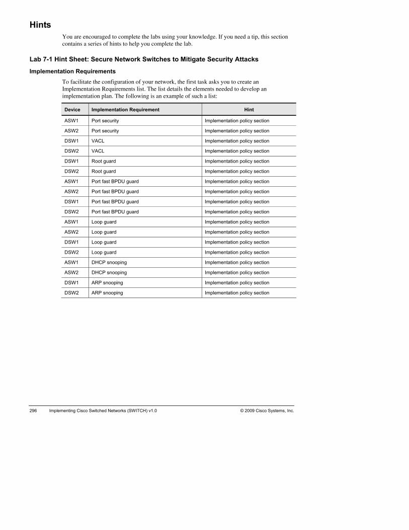
296 Implementing Cisco Switched Networks (SWITCH) v1.0 © 2009 Cisco Systems, Inc.
Hu are encouraged to complete the labs using your knowledge. If you need a tip, this section
conta
Lab 7-1 Hint Sh s
Imur network, the first task asks you to create an
The list details the elements needed to develop an imple
ints Yo
ins a series of hints to help you complete the lab.
eet: Secure Network Switches to Mitigate Security Attack
plementation Requirements To facilitate the configuration of yoImplementation Requirements list.
mentation plan. The following is an example of such a list:
Device Implementation Requirement Hint
ASW 1 Port security Implementation policy section
ASW2 ecu Implementation policy section Port s rity
DSW1 VACL Implementation policy section
DSW2 L Implementation polic VAC y section
DSW1 t gua Implementation polic Roo rd y section
DSW2 t gua Implementation polic Roo rd y section
ASW1 fast Implementation polic Port BPDU guard y section
ASW2 fast BPDU Implementation polic Port guard y section
DSW1 fast BPDU Implementation polic Port guard y section
DSW2 fast Implementation polic Port BPDU guard y section
ASW1 p gua Implementation polic Loo rd y section
ASW2 p gua Implementation polic Loo rd y section
DSW1 ard Implementation polic Loop gu y section
DSW2 Loop guard Implementation policy section
ASW1 P sn Implementation polic DHC ooping y section
ASW2 CP sn Implementation polic DH ooping y section
DSW1 P sno Implementation polic AR oping y section
DSW2 no Implementation polic ARP s oping y section

© 2009 Cisco Systems, Inc. Lab Guide 297
Device High Level Task Information Source
ASW1 ecurity work Diagram, DRequirements
Port s Net esign and Implementation
ASW2 Port security Network Diagram, D ntation Requirements
esign and Impleme
DSW1 Network Diagram, DRequirements
VACL esign and Implementation
DSW2 Network Diagram, DRequirements
VACL esign and Implementation
DSW1 guar Network Diagram, DRequirements
Root d esign and Implementation
DSW2 Root guard Network Diagram, D ntation Requirements
esign and Impleme
ASW1 Port fast BPDU guard Network Diagram, D ntation Requirements
esign and Impleme
ASW2 fast BPD Network Diagram, DRequirements
Port U guard esign and Implementation
DSW1 t B Network Diagram, DRequirements
Port fas PDU guard esign and Implementation
DSW2 t B Network Diagram, DRequirements
Port fas PDU guard esign and Implementation
ASW1 ar Network Diagram, DRequirements
Loop gu d esign and Implementation
ASW2 Loop guard Network Diagram, D ntation Requirements
esign and Impleme
DSW1 Loop guard Network Diagram, D ntation Requirements
esign and Impleme
DSW2 guar Network Diagram, DRequirements
Loop d esign and Implementation
ASW1 P sno Network Diagram, DRequirements
DHC oping esign and Implementation
ASW2 sno Network Diagram, DRequirements
DHCP oping esign and Implementation
DSW1 ARP snooping Network Diagram, Design and Implementation Requirements
DSW2 ARP snooping Network Diagram, D ntation Requirements
esign and Impleme

298 Implementing Cisco Switched Ne ITC .0 © 2009 Cisco Systems, Intworks (SW H) v1 c.
Imd Verification Plan. There are several possible
corretempthe fo
plementation and Verification Plan In this task, you create an Implementation an
ct solutions. One possible approach groups items that are common to all switches in a late and then applies the template to all switches. For this lab, the template could contain llowing items:
Complete √
Device Implemen-tation order
Values and items to implement Verification method and expected results
ASW1 1 show mac address-table interface Fa0/3
ASW1 2 interface FastEthernet0/3
ASW1 witchport por ecurity 3 s t-s
ASW1 switchport port-sct 4 ecurity violation restri
ASW1 witchport por0050.5684.3a29
w port-security rface fastEthernet 5 s t-security mac-address sho
inte0/3
ASW2 e FastEthernet0/3 6 interfac
ASW2 7 switchport port-security
ASW2 8 witchport por sticky interface fastEthernet
0/3
s t-security mac-address show port-security
DSW1 access-list e9 ip xtended NOTEL
DSW1 cp any w access-list 10 permit t any eq telnet sho
DSW1 11 vlan access-map TEST 10
DSW1 tion drop 12 ac
DSW1 13 match ip address NOTEL
DSW1 cess-m14 vlan ac ap TEST 20
DSW1 tion forward15 ac
DSW1 n filter TESom CLT1 and switches does
not work 16 vla T vlan-list 3-4
telnet frCT2 to
DSW2 access-list e17 ip xtended NOTEL
DSW2 cp any access-list 18 permit t any eq telnet show
DSW2 n access-m19 vla ap TEST 10
DSW2 tion drop 20 ac
DSW2 21 match ip address NOTEL
DSW2 n access-m22 vla ap TEST 20
DSW2 23 action forward
DSW2 ilter TEST vlan-lisLT1 and
witches does
24 vlan f t 3-4 CT2 to snot work
telnet from C

© 2009 Cisco Systems, Inc. Lab Guide 299
Complete √
Device Implemen-tation order
Values and items to implement Verification method and expected results
DSW1 25 interface range FastEthernet0/5-6
DSW1 nning-tree g26 spa uard root
DSW2 rface range 27 inte FastEthernet0/5-6
DSW2 28 spanning-tree guard root
ASW1 g-tree portfault 29 spannin ast bpduguard
def
ASW2 spanning-tree portfault 30 ast bpduguard def
DSW1 31 spanning-tree p uguard default ortfast bpd
DSW2 32 nning-tree p uguard default spa ortfast bpd
ASW1 nning-tree lo33 spa opguard default
ASW2 34 spanning-tree loopguard default
DSW1 nning-tree lo35 spa opguard default
DSW2 nning-tree lo36 spa opguard default
ASW1 37 ip dhcp snooping
ASW1 hcp snoopin38 ip d g vlan 1-4094
ASW1 rface range 39 inte FastEthernet0/1-2
ASW1 hcp snoopin nooping 40 ip d g trust show ip dhcp s
ASW2 hcp snoopin 41 ip d g
ASW2 hcp snooping 42 ip d vlan 1-4094
ASW2 erface range Fast43 int Ethernet0/1-2
ASW2 hcp snooping oping g 44 ip d trust show ip dhcp sno
bindin
DSW1 arp inspection v45 ip lan 1-4094
DSW2 rp inspection 46 ip a vlan 1-4094
DSW1 rface range 47 inte FastEthernet0/5 - 7
DSW1 rp inspection ction 48 ip a trust show ip arp inspestatistics vlan 3
DSW2 rface range 49 inte FastEthernet0/5 - 7
DSW2 rp inspection show ip arp inspection n 4 50 ip a trust statistics vla

300 Implementing © 2009 Cisco Systems, Inc. Cisco Switched Networks (SWITCH) v1.0
StSt tch interface in configuration mode:
l.
Step 2 Confi
ASW1(cASW1
Step 3 Configur
ASW2ASW2ASW2
olation restrict ASW2ASW2PortPortViolAginAginSecuMaxiTotaConfSticLastSecu
Step 4 Configur
DSW1DSW1 telnet DSW1DSW1DSW1 DSW1
DSW1DSW1DSW1Exte DSW1Vlan Ma Ac Vlan Ma Ac
ep-by-Step Procedure ep 1 Connect to switch ASW1 swi
Connect to the remote lab.
Access the Switch console.
Enter privilege mode, using enable.
Enter configuration mode, using configure termina
gure port security on switch ASW1:
ASW1#sho mac address-table interface FastEthernet 0/3 ASW1(config)#interface FastEthernet0/3 ASW1(config-if)# switchport port-security
onfig-if)# switchport port-security mac-address sticky (config-if)# switchport port-security violation restrict
e port security on switch ASW2:
#sho mac address-table interface FastEthernet 0/3 (config)#interface FastEthernet0/3 (config-if)# switchport port-security
c-address sticky ASW2(config-if)# switchport port-security maASW2(config-if)# switchport port-security vi
(config-if)# end # ASW2#show port-security interface f0/3 Security : Enabled Status : Secure-up ation Mode : Restrict g Time : 10 mins
activity g Type : InreStatic Address Aging : Disabled mum MAC Addresses : 1 l MAC Addresses : 1 igured MAC Addresses : 0 ky MAC Addresses : 1 Source Address:Vlan : 0050.5684.32ac:4 rity Violation Count : 0
e VACL on switch DSW1:
(config)#ip access-list extended NOTEL (config-ext-nacl)# permit tcp any any eq
(config)#vlan access-map TEST 10 (config-access-map)# action drop (config-access-map)#match ip address NOTEL
(config)#vlan access-map TEST 20 DSW1(config-access-map)# action forward
(config)#vlan filter TEST vlan-list 3-4 (config)# end show access-lists #
nded IP access list 100 10 permit tcp any any eq telnet #show vlan access-map access-map "DROP" 10 h clauses: tc
ip address: 100 tion: drop ccess-map "DROP" 20 a
tch clauses: tion: forward

© 2009 Cisco Systems, Inc. Lab Guide 301
Step 5 Repeat step 4 on switch DSW2.
Step 6 Configure STP security on switch ASW1:
d default ASW1(
Step 7 Repeat ste
Step 9 Repeat ste
Step 10 Configure
ASW1(config)# ip dhcp snooping vlan 1-4094 2
ASW1#SwitcDHCP 1-409DHCP 1,4,1DHCP Interfaces: Inser ci rOptioVerifVerifDHCP Inter t (pps) ----- ------- FastEFastE
Step 11 Repeat ste
Step 12 Configure
DSW1(DSW1(DSW1( DSW1#
ASW1(config)# spanning-tree portfast bpduguarconfig)# spanning-tree loopguard default
p 6 on switches ASW2, DSW1, and DSW2.
Step 8 Configure root guard on switch DSW1:
DSW1(config)# interface FastEthernet0/5 DSW1(config-if)# spanning-tree guard root
p 8 on switch DSW2.
DHCP snooping on switch ASW1:
ASW1(config)# ip dhcp snooping
ASW1(config)# interface range FastEthernet0/1 - ASW1(config-if)# ip dhcp snooping trust
show ip dhcp snooping h DHCP snooping is enabled snooping is configured on following VLANs: 4 ooping is operational on following VLANs: sn
1-12,63-66 snooping is configured on the following L3
tion of option 82 is enabled mat: vlan-mod-port rcuit-id for
emote-id format: MAC rt is not allowed n 82 on untrusted po
ication of hwaddr field is enabled ication of giaddr field is enabled ooping trust/rate is configured on the following Interfaces: sn
face Trusted Rate limi------------------- ------- ---------
unlimited thernet0/1 yes thernet0/2 yes unlimited
p 10 on switch ASW2.
ARP inspection on switch DSW1:
config)# ip arp inspection vlan 1-4094 config)# interface range FastEthernet0/5 - 7 config-if)# ip arp inspection trust
sho ip arp inspection
Source Mac Validation : Disabled Destination Mac Validation : Disabled IP Address Validation : Disabled

302 Implementing Cisco Switched Networks (SWITCH) v1.0 © 2009 Cisco Systems, Inc.
Vla --- 1 1 1 Vla ---…/… Vlan --- 408 408 409 409 409 409 409
Step 13 Repeat st
n Configuration Operation ACL Match Static ACL - ------------- --------- --------- ---------- 1 Enabled Active 2 Enabled Inactive 3 Enabled Active 4 Enabled Active 5 Enabled Inactive 6 Enabled Inactive 7 Enabled Inactive 8 Enabled Inactive 9 Enabled Inactive 0 Enabled Inactive 1 Enabled Active 2 Enabled Active n Configuration Operation ACL Match Static ACL - ------------- --------- --------- ---------- (long output ommited)
res IP Validation Failures Invalid Protocol Data Dest MAC Failu- ----------------- ---------------------- --------------------- 8 0 0 0
0 0 9 0 0 0 0 0 1 0 0 0 2 0 0 0 3 0 0 0 4 0 0 0
ep 12 on switch DSW2.

© 2009 Cisco Systems, Inc. Lab Guide 303
LaVo
ourse on the topics of High
Activity Obj the IT manager that a VoIP solution is expected to be Your task is to make the needed changes and prepare the network way that it will work without interruption. An email from the
voice list of tinfrastand Hiinformof the
After c
Ga
Pr ments list for VoIP readiness.
Prepare
Im
b 8-1: Plan Implementation and Verification of IP in a Campus Network
Complete this lab activity to confirm your knowledge from the cavailability and reporting.
ective You receive information fromimplemented in a near future.for the future project in such a
consultant informs you that the voice part of the implementation will be externalized. A he planned voice equipment is attached. Your assignment is to prepare the wired
ructure for this addition. You will have to design the voice VLANs, Auto QoS, DHCP gh availability features for to prepare the network. Your first task is to analyze the ation and make a plan for the needed steps to prepare the network for the implementation voice solution.
ompleting this activity, you will be able to meet these objectives:
ther information regarding the implementation of VoIP.
epare implementation require
an implementation and verification plan.
plement and verify.

304 Implementing Cisco Switched Networks (SWITCH) v1.0 © 2009 Cisco Systems, Inc.
Ination needed to accomplish in this activity. Read it carefully.
The Ialong
Implementatioe in your network. The following lists details preparation and s for all switches in the company network. Your configuration must
imple
II
For every switch port connecting an IP phone, you have to allow the Voice VLAN (VLAN
tch DSW2 must
oth
the DHCP scopes.
tween switches, and access ports to CMEs.
to plan and configure PoE to support IP phones where needed.
formation Packet This packet contains the inform
nformation Packet describes the requirements common to all devices in the network, with information specific to each device.
n Policy You have to integrate voicconfiguration requirement
ment all these requirements:
P phones will be connected to switches ASW1 and ASW2. Refer to the Device nformation table and configure each port accordingly.
63 on switch ASW1 and VLAN 64 on switch ASW2) and a data VLAN (VLAN 3 on switch ASW1 and VLAN 4 on switch ASW2).
Cisco Unified Call Manager Express units (CMEs) will be connected to switches DSW1 and DSW2 as per the Devices Information section information.
The CME on switch DSW1 must be in Voice VLAN 63, the CME on swibe in Voice VLAN 64.
HSRP on switches DSW1 and DSW2 for Voice VLAN (VLAN 63 and VLAN 64) should be configured. Switch DSW1 should be the primary gateway with a priority of 120. Bswitches DSW1 and DSW2 should preempt. Both switches DSW1 and DSW2 should track their links to switches CSW1 and CSW2. Loss of connectivity to either Core switch should decrease the priority by 30.
Switches DSW1 and DSW2 should be DHCP servers for Voice VLAN (VLAN 63 and VLAN 64). For each Voice VLAN, DSW1 will distribute addresses .50 to .99, and switch DSW2 will distribute addresses .100 to .149.
You should configure option 150 in each DHCP scope and point VLAN 63 DHCP clients to CME1 IP address, and VLAN 64 DHCP clients to CME2 IP address. Make sure that both CME IP addresses are excluded from
Verify that routing is properly configured to allow communication between these various VLANs.
You should configure Auto QoS on access ports to IP phones, trunk ports be
Class of service (CoS) values sent by IP phones and PCs connected to them should be trusted.
Power adapters were ordered along with the phones. Some Power over Ethernet (PoE) switches will be added to your network at a later date. Use the Task 2 section to make sure that you know how

Devmation about device locations:
ices Information The table provides infor
Role IP address Network loDevice cation
IP phon IP phone DHCP assigned W1 P4 e 1 AS
IP phon one DHCP assigned 5 e 2 IP ph ASW1 P
IP phone 3 IP phone DHCP assigned ASW2 P4
IP phon one DHCP assigned 5 e 4 IP ph ASW2 P
CME 1 g 10.1.63.11/24 Call Mana er Express DSW1 P6
CME 2 g 10.1.64.12/24 Call Mana er Express DSW2 P6
Network Diagram
© 2009
bjective for Lab 8-1: Plan ntation of VoIP in a Campus Network
Visual OImpleme
Cisco Systems, Inc. All rights reserved. SWITCH v1.0—52
© 2009 Cisco Systems, Inc. Lab Guide 305

306 Implementing Cisco Switched Networks (SWITCH) v1.0 © 2009 Cisco Systems, Inc.
Ce commands that are used in this activity.
ommand List The table describes th
Command Description
auto isco-phone
Enables auto-Q d specify that the port is connected to a
qos voip c oS on the port, an Cisco IP Phone.
The QoS labelCisco IP Phon
s of incoming packets are trusted only when the e is detected.
auto qos voip trust Enables auto-Qconnected to a
oS on the port, and specify that the port is trusted router or switch.
cdp CDP globally. By default, it is enabled. enable Enables
mls
gures the he pack
default CoS va
qos trust cos Confiusing t
interface to classify incoming traffic packets by et CoS value. For untagged packets, the port lue is used.
inte net | giga
interface configuration mode for a Cisco Catalyst switch ith a Fast Eth
rface fastetherbitethernet slot/port
Entersw ernet or Gigabit Ethernet interface installed
interfafastethernet | gigaslotendi
ts a rangce range Selec
bitethernet /starting_port - ng_port
e of interfaces to configure.
ip h Enables forwarforwarding UD
elper-address address ding and specify the destination address for P broadcast packets, including BOOTP.
ip d Creates a name for the DHCP server address pool and enters P pool configuration mode.
hcp pool pool-name DHC
netw ask | /prefix
Specifies the IP address of the DHCP address pool to be configured.
ork ip-address [m-length]
opti TCisco nified I
is you
on 150 ip ip-address Specifies the FTP server address from which the P phone downloads the image configuration file. U
This r Cisco Unified CME router's address. default-router ip-address (Optional) Spe to
ceivecifies the router that the IP phones will use
send or re IP traffic that is external to their local subnet.
leas[min
(Optional) Spe of the lease.
fault
The infileas
e {days [hours] utes]| infinite} The de
cifies the duration
is a one-day lease.
nite keyword specifies that the duration of the e is unlimited.

© 2009 Cisco Systems, I Lab Guide 307 nc.
Command Description
switchport voice vlan {vlanuntag
Configures how the Cisco IP Phone carries voice traffic:
an-id ffi
priorit
dot1p prioritVLAN
priorit
none send
untagg ne to send untagged
-id | dot1p | none | ged}}
vltraPh
— Configure the phone to forward all voice c through the specified VLAN. By default, the Cisco IP
one forwards the voice traffic with an IEEE 802.1Q y of 5. Valid VLAN IDs are 1 to 4094.
— Configure the phone to use IEEE 802.1p y tagging for voice traffic and to use the default native (VLAN 0) to carry all traffic. By default, the Cisco IP
Phone forwards the voice traffic with an IEEE 802.1p y of 5.
— Allow the phone to use its own configuration to untagged voice traffic.
— Configure the phoed voice traffic.
switchport priority extend {cos value | trust}
Sets the hone access port:
priorit attached device with the specifiewith 7 as th
trust — one access port to trust the o
priority of data traffic received from the Cisco IP P
cos value — Configure the phone to override the y received from the PC or the
d CoS value. The value is a number from 0 to 7, e highest priority. The default priority is cos 0.
Config hure the ppri rity received from the PC or the attached device.
show interfaces interface-id switchport
Verify your entries.
Job Aids These are the job aids for this lab activity:
Value Location
Blank implementation requirements Task 1 list
Blank implementation and verification plan form Task 2
Blank student notes Task 3
Debri ab ef alternate solutions form End of this l
Implem equirement hints Hint Section entation r
Implementation hints Hint Section
Verifica Section tion hints Hint
Solution ectio nd of the lab guide configure answer key Configuration s n at the e

308 Implementing Cisco Switched Networks (SWITCH) v1.0 © 2009 Cisco Systems, Inc.
TIn
et, your first task is to create a list where you will documlab vimpleat the
ask 1: Create an Implementation Requirement List for VoIP tegration in the Campus
After you have analyzed the Information Packent the requirements for a successful implementation. Use the following table, the initial
isual objective, and the implementation policy and devices information to create your mentation requirement list. If you are unsure, you can use the hints information provided end of the lab guide.
Device High Level Task Information Source

© 2009 Cisco Systems, Inc. Lab Guide 309
Ta
on eacbecausorder. you wimplemthe Imat the
sk 2: Create an Implementation and Verification Plan The next step in your configuration deployment is to create a task list of each item to configure
h device and in what order. The Implementation and Verification Plan is very important, e it enables you to ensure that all requirements are properly configured and in the correct The task will help you setup configuration checkpoints. Use the plan to determine how ill verify that each required item was effectively configured. You will move to the actual
entation in the next task. Use the following table and the Information Packet to create plementation and Verification Plan. If you are unsure, use the hints information provided end of this lab.
Complete √
Device Implementation order
Values and items to implement
Verification method and expected results

310 Implementing Cisco Switched Networks (SWITCH) v1.0 © 2009 Cisco Systems, Inc.
Complete √
Device Implementation order
Values and items to implement
Verification method and expected results

© 2009 Cisco Systems, Inc. Lab Guide 311
PoE configuration: PoE switches will be added later to your network. Answer the following questi
1. Ho nes be powered?
_______________________________
______
2. Are all PoE switches the same?
_________________________________
________________________________________________________________________
3. Are all
______
4. Are other PoE devices likely to be installed in the network?
________________________________________________________________________
________
Phones:
______
______
________________________________________________________________________
________________________________________________________________________
______
ons:
w will the pho
_________________________________________
__________________________________________________________________
_______________________________________
PoE devices equal (requiring the same power from the PoE switch)?
__________________________________________________________________
________________________________________________________________________
________________________________________________________________
5. Document the steps and commands required to configure PoE on switch ports to IP
__________________________________________________________________
__________________________________________________________________
________________________________________________________________________
__________________________________________________________________

312 Implementing Cisco Switched Networks (SWITCH) v1.0 © 2009 Cisco Systems, Inc.
Tplanned the implementation, you are ready
to cosolutspeciyour verifi
ask 3: Implement and Verify Now that you have all of the requirements and have
nnect to the remote lab and implement your solution. Do not forget to save! Once your ion is implemented, verify your configuration is working and fulfills the requirements fied. Use the previous table to document the verifications you conducted to ensure that solution is complete. Hints are available at the end of this lab if you are unsure about the cation steps.

© 2009 Cisco Systems, Inc. Lab Guide 313
Ste to document the details that you think are important to remember.
____
______
______
__________
__________________________________________________________________________
__________
______
______
______
__________________________________________________________________________
__________________________________________________________________________
______
______
______
__________
__________________________________________________________________________
__________
______
______
______
__________________________________________________________________________
__________________________________________________________________________
______
______
______
__________
udent Notes Use the following spac
______________________________________________________________________
____________________________________________________________________
____________________________________________________________________
________________________________________________________________
________________________________________________________________
____________________________________________________________________
____________________________________________________________________
____________________________________________________________________
____________________________________________________________________
____________________________________________________________________
____________________________________________________________________
________________________________________________________________
________________________________________________________________
____________________________________________________________________
____________________________________________________________________
____________________________________________________________________
____________________________________________________________________
____________________________________________________________________
____________________________________________________________________
________________________________________________________________

314 Implementing Cisco Switched Networks (SWITCH) v1.0 © 2009 Cisco Systems, Inc.
_____
__________________________________________________________________________
_____
_____
_____
_____
__________________________________________________________________________
__________________________________________________________________________
_____
_____
_____
_____
__________________________________________________________________________
_____
_____
_____
_____
__________________________________________________________________________
__________________________________________________________________________
_____
_____
_____
_____
__________________________________________________________________________
_____
_____
_____________________________________________________________________
_____________________________________________________________________
_____________________________________________________________________
_____________________________________________________________________
_____________________________________________________________________
_____________________________________________________________________
_____________________________________________________________________
_____________________________________________________________________
_____________________________________________________________________
_____________________________________________________________________
_____________________________________________________________________
_____________________________________________________________________
_____________________________________________________________________
_____________________________________________________________________
_____________________________________________________________________
_____________________________________________________________________
_____________________________________________________________________
_____________________________________________________________________
_____________________________________________________________________

© 2009 Cisco Systems, Inc. Lab Guide 315
Al
duringother p
_____ ________________________________________
______
______
__________________________________________________________________________
__________________________________________________________________________
______
______
______
__________
__________________________________________________________________________
__________
______
______
______
__________________________________________________________________________
__________________________________________________________________________
______
______
______
__________
__________________________________________________________________________
__________
______
______
______
ternate Resources and Solutions to the One You Used Other groups may use a solution different from yours. Possible solutions will be discussed
the debrief period after the lab. For your reference, use the following space to document ossible solutions.
_____________________________
____________________________________________________________________
____________________________________________________________________
____________________________________________________________________
____________________________________________________________________
____________________________________________________________________
________________________________________________________________
________________________________________________________________
____________________________________________________________________
____________________________________________________________________
____________________________________________________________________
____________________________________________________________________
____________________________________________________________________
____________________________________________________________________
________________________________________________________________
________________________________________________________________
____________________________________________________________________
____________________________________________________________________
____________________________________________________________________

316 Implementing Cisco Switched Networks (SWITCH) v1.0 © 2009 Cisco Systems, Inc.
_____
__________________________________________________________________________
_____
_____
_____
_____
__________________________________________________________________________
__________________________________________________________________________
_____
_____
_____
_____
__________________________________________________________________________
_____
_____
_____
_____
__________________________________________________________________________
__________________________________________________________________________
_____
_____
_____
_____
__________________________________________________________________________
_____
_____________________________________________________________________
_____________________________________________________________________
_____________________________________________________________________
_____________________________________________________________________
_____________________________________________________________________
_____________________________________________________________________
_____________________________________________________________________
_____________________________________________________________________
_____________________________________________________________________
_____________________________________________________________________
_____________________________________________________________________
_____________________________________________________________________
_____________________________________________________________________
_____________________________________________________________________
_____________________________________________________________________
_____________________________________________________________________
_____________________________________________________________________
_____________________________________________________________________

© 2009 Cisco Systems, Inc. Lab Guide 317
La_____________
______
______
______
__________
__________________________________________________________________________
__________
______
______
______
__________________________________________________________________________
__________________________________________________________________________
______
______
______
__________
__________________________________________________________________________
__________
______
______
______
__________________________________________________________________________
__________________________________________________________________________
______
______
______
__________
b 8-1: Key Commands and Tools Used _____________________________________________________________
____________________________________________________________________
____________________________________________________________________
____________________________________________________________________
________________________________________________________________
________________________________________________________________
____________________________________________________________________
____________________________________________________________________
____________________________________________________________________
____________________________________________________________________
____________________________________________________________________
____________________________________________________________________
________________________________________________________________
________________________________________________________________
____________________________________________________________________
____________________________________________________________________
____________________________________________________________________
____________________________________________________________________
____________________________________________________________________
____________________________________________________________________
________________________________________________________________

318 Implementing Cisco Switched Networks (SWITCH) v1.0 © 2009 Cisco Systems, Inc.
Hu are encouraged to complete the labs using your knowledge. If you need a tip, this section
conta
Lab 8-1 Hint Sh a Campus N
ImTo facilitate the configuration of your network, the first task asks you to create an
The list details the elements needed to develop an g is an example of such a list:
ints Yo
ins a series of hints to help you complete the lab.
eet: Plan Implementation and Verification of VoIP in etwork
plementation Requirements
Implementation Requirements list.implementation plan. The followin
Device Implementation Requirement Hint
ASW 1 IP Phone 1 Implementation policy section
ASW1 IP Phone 2 mentation policy section Imple
ASW2 IP Phone 3 Implementation policy section
ASW2 IP Phone 4 Implementation policy section
DSW1 CME 1 Implementation polic y section
DSW1 HSRP Implementation polic y section
DSW1 DHCP Implementation polic y section
DSW2 HSRP Implementation policy section
DSW2 CME 2 Implementation policy section
DSW2 DHCP Implementation policy section
All sw Auto QoS Implementation policitches y section

© 2009 Cisco Systems, Inc. Lab Guide 319
Device High Level Task Information Source
ASW1 IP Phone 1 work Diagram, D Requirements Net esign and Implementation
ASW1 IP Phone 2 Network Diagram, D ntation Requirements
esign and Impleme
ASW2 one Network Diagram, DRequirements IP Ph 3 esign and Implementation
ASW2 one Network Diagram, DRequirements IP Ph 4 esign and Implementation
DSW1 1 Network Diagram, DRequirements CME esign and Implementation
DSW2 CME 2 Network Diagram, D ntation Requirements
esign and Impleme
DSW1 HSRP Network Diagram, D ntation Requirements
esign and Impleme
DSW2 HSRP Network Diagram, DRequirements
esign and Implementation
DSW1 Network Diagram, DRequirements DHCP esign and Implementation
DSW2 Network Diagram, DRequirements DHCP esign and Implementation
All switche
Network Diagram, DRequirements s Auto QoS esign and Implementation

320 Implementing Cisco Switched Ne ITC .0 9 Cisco Systems, tworks (SW H) v1 © 200 Inc.
Imd Verification Plan. There are several possible
corretempthe fo
plementation and Verification Plan In this task, you create an Implementation an
ct solutions. One possible approach groups items that are common to all switches in a late and then applies the template to all switches. For this lab, the template could contain llowing items:
Complete √
Device Imple-menta-tion order
Values and items to implement Verification method and expected results
ASW1 1 face range hernet0/14-15
interFastEt
ASW1 2 tchporswi t mode access
ASW1 3 switchport access vlan 3
ASW1 tchpor4 swi t voice vlan 63
ASW1 tchporst
5 switru
t priority extend
ASW1 qos t mls rust cos
ASW1 6 qos tcisco-phomls rust device
ne sh interface Fa0/14
ASW1 7 auto qos voip cisco-phone sh mls qos int f 0/14
ASW2 8 interface range FastEthernet0/14-15
ASW2 9 switchport mode access
ASW2 10 switchport access vlan 4
ASW2 11 switchport voice vlan 64
ASW2 12 switchport priority extend trust
ASW2 13 mls qos trust cos
ASW2 14 mls qos trust device cisco-phone
sh interface Fa0/14
ASW2 15 auto qos voip cisco-phone sh mls qos int f 0/14

© 2009 Cisco Systems, Inc. Lab Guide 321
Complete √
Device Imple-menta-tion order
Values and items to implement Verification method and expected results
DSW1 16 Interface Fastethernet 0/15
DSW1 Switchport17 mode access
DSW1 S rt18 witchpo access vlan 63
DSW2 19 Interface Fastethernet 0/15
DSW2 20 S rtwitchpo mode access
DSW2 21 Switchport vlan 64 access
DSW1 I ex1 1
22 p dhcp 0.1.63.
cluded-address 10.1.63.49
DSW1 I ex1 10
23 p dhcp 0.1.63.
cluded-address 0 10.1.63.255
DSW1 Ip dhcp ex1 1
24 cluded-address 10.1.64.49
0.1.64.
DSW1 25 Ip dhcp ex1 10
cluded-address 0.1.64. 0 10.1.64.255
DSW1 26 ip dhcp pool vlan63
DSW1 n rk 10255.255.25
27 etwo .1.63.0 5.0
DSW1 default-ro28 uter 10.1.63.1
DSW1 o 5010.1.64.12
29 ption 1 ip 10.1.63.11
DSW1 lease 8 dhcp pool
30 show ip
DSW1 i po31 p dhcp ol vlan64
DSW1 32 n rk 10255.255.25etwo .1.64.0
5.0
DSW1 33 default-router 10.1.64.1
DSW1 option 150 i 3.11 10.1.64.12
34 p 10.1.6
DSW1 l dhcp pool
35 ease 8 show ip

322 Implementing Cisco Switched Ne ITCH) v1.0 © 2009 Cisco Systems,tworks (SW Inc.
Complete √
Device Imple-menta-tion order
Values and items to implement Verification method and expected results
DSW2 36 Ip dhcp excluded-address 10.1.63.1 10.1.63.99
DSW2 37 Ip dhcp excluded-address 10.1.63.150 10.1.63.255
DSW2 38 Ip dhcp excluded-address 10.1.64.1 10.1.64.99
DSW2 39 Ip dhcp excluded-address 10.1.64.150 10.1.64.255
DSW2 40 ip dhcp pool vlan63
DSW2 41 network 10.1.63.0 255.255.255.0
DSW2 42 default-router 10.1.63.1
DSW2 43 option 150 ip 10.1.63.11 10.1.63.12
DSW2 44 lease 8 show ip dhcp pool
DSW2 45 ip dhcp pool vlan64
DSW2 46 network 10.1.64.0 255.255.255.0
DSW2 47 default-router 10.1.64.1
DSW2 48 option 150 ip 10.1.63.11 10.1.64.12
DSW2 49 lease 8 show ip dhcp pool
DSW1 ce50 interfa Vlan 63
DSW1
51 ddres.2
ow
ip interface brief
ip a255.255
s 10.1.63.3 55.0
sh interfaceVlan 63 / sh
DSW1 standby 6 3.1 52 3 ip 10.1.6
DSW1 53 standby 63 priority 120
DSW1 54 standby 63 preempt

© 2009 Cisco Systems, I uide 3nc. Lab G 23
Complete √
Device Imple-menta-tion order
Values and items to implement Verification method and expected results
DSW1 55 standby 63 track Port-channel31 30
DSW1 standby 63channel32
sh stanby 56 track Port-30
DSW1 i e 57 nterfac Vlan 64
DSW1
58 ip address 10.1.64.3 2 25
sh interfave / show face
55.255. 5.0 vlan 64 ip interbrief
DSW1 standby 64 59 ip 10.1.64.1
DSW1 60 standby 64 priority 90
DSW1 standby 6461 preempt
DSW1 62 standby 64 track Port-c 1
hannel3 30
DSW1 standby 64c 2
63 track Port-30
hannel3
DSW2
64 i e nterfac Vlan 63 sh interface Vlan 63 / show ip interface brief
DSW2 65 ip address 10.1.63.2 255.255.255.0
DSW2 66 s 63tandby ip 10.1.63.1
DSW2 67 standby 63 track Port-channel31 30
DSW2 68 standby 63 track Port-c 2 hannel3 30
DSW2 69 standby 63 preempt sh stanby
DSW2
70 interface Vlan 64 Sh interface vlan 64 / show ip interface brief

324 Implementing Cisco Switched Ne ITC .0 Cisco Systems, tworks (SW H) v1 © 2009 Inc.
Complete √
Device Imple-menta-tion order
Values and items to implement Verification method and expected results
DSW2 71 ip address 10.1.64.3 255.255.255.0
DSW2 72 standby 64 ip 10.1.64.1
DSW2 73 standby 64 priority 120
DSW2 74 standby 64 track Port-channel31 30
DSW2 75 standby 64 track Port-channel32 30
DSW2 76 Standby 64 preempt Sh standby
ASW1 77 interface range FastEthernet0/1-2
ASW1 78 auto qos voip trust
ASW2 79 interface range FastEthernet0/1-2
ASW2 80 auto qos voip trust
DSW1
81 interface range FastEthernet0/1-7 , FastEthernet0/15
DSW1 82 auto qos voip trust
DSW2
83 interface range FastEthernet0/1-7 , FastEthernet0/15
DSW2 84 auto qos voip trust
CSW1
interface rer
FastEther
85 ange FastEth net0/1-4 ,
net0/7-12
CSW1 s 86 auto qo voip trust
CSW2
87 interface range FastEthernet0/1-4 , FastEthernet0/7-12
CSW2 88 auto qos voip trust

© 2009 Cisco Systems, Inc. Lab Guide 325
PoE configuration:
1. How will the phones be powered?
With AC power cords at first, PoE will be needed later.
2. Are all PoE s
Power, some only have power for a number of ports etc, negotiation can take place or not, there are many differences between
witches the same?
No. Some provide standard PoE, some High
models.
3. Are all PoE
No. Some use MORE, some can negotiate.
devices equal (requiring the same power from the PoE switch)?
use less power, some
4. Are other PoE devices likely to be installed in the network?
Very likely, many devices use PoE, although the list is not clearly stated in this lab.
IP Phones use standard PoE. To enable this feature for example on interface f0/1, use the command sequence:
Switch(config)Switch(config-
# interface FastEthernet0/1 if)# power inline auto
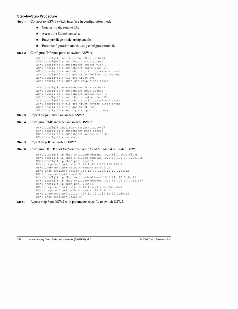
326 Implementing ems, Inc. Cisco Switched Networks (SWITCH) v1.0 © 2009 Cisco Syst
StSt rface in configuration mode
.
Step 2 Confi
ASW1(cASW1ASW1ASW1ASW1 ASW1ASW1ASW1ASW1ASW1ASW1ASW1ASW1
Step 3 Repeat st
Step 4 Configur
DSW1DSW1DSW1
n switch DSW1:
DSW1 .49 DSW1 63.255 DSW1DSW1DSW1
.63.11 10.1.64.12
DSW1(config)# ip dhcp excluded-address 10.1.641 10.1.64.49
DSW1DSW1DSW1DSW1
Step 7 Repeat st
ep-by-Step Procedure ep 1 Connect to ASW1 switch inte
Connect to the remote lab.
Access the Switch console.
Enter privilege mode, using enable.
Enter configuration mode, using configure terminal
gure IP Phone ports on switch ASW1:
ASW1(config)# interface FastEthernet0/14 ASW1(config-if)# switchport mode access ASW1(config-if)# switchport access vlan 3
onfig-if)# switchport voice vlan 63 (config-if)# switchport priority extend trust (config-if)# mls qos trust device cisco-phone (config-if)# mls qos trust cos (config-if)# auto qos voip cisco-phone
(config)# interface FastEthernet0/15 (config-if)# switchport mode access (config-if)# switchport access vlan 3 (config-if)# switchport voice vlan 63 onfig-if)# switchport priority extend trust (c
(config-if)# mls qos trust device cisco-phone (config-if)# mls qos trust cos (config-if)# auto qos voip cisco-phone
eps 1 and 2 on switch ASW2.
e CME interface on switch DSW1:
(config)# interface FastEthernet0/15 (config-if)# switchport mode access (config-if)# switchport access vlan 63 (config-if)# no shut DSW1
Step 5 Repeat step 10 on switch DSW2.
Step 6 Configure DHCP pool for Voice VLAN 63 and VLAN 64 o
(config)# ip dhcp excluded-address 10.1.63.1 10.1.631.(config)# ip dhcp excluded-address 10.1.63.100 10.
(config)# ip dhcp pool vlan63 (dhcp-config)# network 10.1.63.0 255.255.255.0
.1.63.1 (dhcp-config)# default-router 10(dhcp-config)# option 150 ip 10.1DSW1
DSW1(dhcp-config)# lease 8
DSW1(config)# ip dhcp excluded-address 10.1.64.100 10.1.64.255 DSW1(config)# ip dhcp pool vlan64
(dhcp-config)# network 10.1.64.0 255.255.255.0 (dhcp-config)# default-router 10.1.64.1 (dhcp-config)# option 150 ip 10.1.63.11 10.1.64.12 (dhcp-config)# lease 8
ep 6 on DSW2 with parameters specific to switch DSW2.

© 2009 Cisco Systems, Inc. Lab Guide 327
Step 8 Configure interface VLAN 63 and VLAN 64 on switch DSW1:
DSW1(config)# interface Vlan 63 DSW1( 55.0 DSW1(DSW1(DSW1(DSW1(DSW1(DSW1(DSW1(DSW1(DSW1(DSW1(DSW1(DSW1(
Step 9 Repeat ste
Step 10 Configure
QoS i ASW1#FastEtrusttrusttrustCOS odefauDSCP ion Map Trustqos m ASW1#Build Curre bytes ! inter swit ,3,11,63,65 swit srr- 60 20 prio mls auto ip dend
Step 11 Repeat ste
config-if)# ip address 10.1.63.3 255.255.2config-if)# standby 63 ip 10.1.63.1 config-if)# standby 63 priority 120 config-if)# standby 63 preempt config-if)# standby 63 track Port-channel31 30
0 config-if)# standby 63 track Port-channel32 3config)# interface Vlan 64 config-if)# ip address 10.1.63.3 255.255.255.0 config-if)# standby 64 ip 10.1.64.1 config-if)# standby 64 priority 90 config-if)# standby 64 preempt config-if)# standby 64 track Port-channel31 30 config-if)# standby 64 track Port-channel32 30
2. p 8 on DSW2 with parameters specific to switch DSW
QoS at the interface level on switch ASW1:
ASW1(config)# interface range FastEthernet0/1-2 ASW1(config-if)# auto qos voip trust
ASW1#sh mls qos QoS is enabled
p packet dscp rewrite is enabled
shther mls qos int f0/1 net0/1
state: trust cos mode: trust cos enabled flag: ena rride: dis ve
lt COS: 0 Mutation Map: Default DSCP Mutat device: none ode: port-based
sh run int f0/1 ing configuration...
nt configuration : 225
face FastEthernet0/1 chport trunk allowed vlan 1chport mode trunk
e bandwidth share 10 10queurity-queue out qos trust cos os voip trust q
hcp snooping trust
p 10 on switch ASW2.

328 Implementing Cisco Switched Networks (SWITCH) v1.0 © 2009 Cisco Systems, Inc.
Step 12 Configure trunk interfaces for QoS on switch DSW1:
DSW1(config)# interface range FastEthernet0/5-7 , FastEthernet0/15 DSW1 DSW1QoS QoS e is enabled DSW1FasttrustrustrusCOS defaDSCP ation Map Trusqos DSW1Fastauto Fastauto Fastauto Fastauto Fastauto Fastauto Fastauto Fastauto
Step 13 Repeat st
Step 14 Configur tch CSW1:
CSW1 ange FastEthernet0/1-4 , FastEthernet0/7-12 CSW1 trust
Step 15 Repeat st
(config-if)# auto qos voip trust
#sis h mls qos enabled
ip packet dscp rewrit
#sh mls qos int f0/7 hernet0/7 Et
t state: trust cos t mode: trust cos t enabled flag: ena override: dis ult COS: 0 Mutation Map: Default DSCP Mutt device: none mode: port-based
#sh auto qos Ethernet0/1 qos voip trust
net0/2 Ether qos voip trust
Ethernet0/3 qos voip trust
Ethernet0/4 qos voip trust
Ethernet0/5 qos voip trust
Ethernet0/6 qos voip trust
Ethernet0/7 ip trust qos vo
Ethernet0/15 os voip trust q
ep 12 on switch DSW2.
e trunk interfaces for QoS on swi
(config)# interface r(config-if)# auto qos voip
14 on switch CSW2. ep

© 2009 Cisco Systems, Inc. Lab Guide 329
Laavailab
Activity Objng, your IT manager informed you that, after voice, wireless o the existing network. You must prepare the switched network
for a winformplannefor thineeded
After c
Id
Prepare an implementation plan for wireless integration.
Pr
b 9-1: Integrating Wireless in the Campus Complete this lab activity to confirm your knowledge from the course on the topics of High
ility and reporting.
ective During a daily morning meeticapabilities should be added t
ireless integration that will take place next month. An email from the wireless consultant s you that the wireless part of the implementation will be externalized. A list of the d wireless equipment is attached. Your assignment is to prepare the wired infrastructure s wireless addition. Your first task is to analyze the information and make a plan for the steps to prepare the network for the implementation of the wireless solution.
ompleting this activity, you will be able to meet these objectives:
entify the requirements for implementing wireless structure in a network.
epare the switched network for integration of wireless equipment.
Verify that the switched network was properly provisioned.

330 Implementing Cisco Switched Networks (SWITCH) v1.0 © 2009 Cisco Systems, Inc.
Ination needed to accomplish in this activity. Read it carefully.
The Ialong
Implementatioless in your network. The following lists details preparation and s for all switches in the company network. Your configuration must
imple
SR
WCS and WLC will be connected to DSW1 and DSW2 per the Devices Information
One Hybrid Remote Edge Access Point (HREAP) must be connected to each access switch.
LAN (VLAN 4). The configuration of the configuration of a port to an autonomous
SW2 must be in the VLAN 4.
.
know how to configure t series of access points to be
formation Packet This packet contains the inform
nformation Packet describes the requirements common to all devices in the network, with information specific to each device.
n Policy You have to integrate wireconfiguration requirement
ment all these requirements:
everal standard Cisco 1240 series access points will be connected to ASW1 and ASW2. efer to the Device Information table and configure each port accordingly.
section.
For the autonomous AP on ASW1, allow the voice VLAN (VLAN 63) and data VLAN (VLAN 3). For the autonomous AP on ASW2, you have to allow the voice VLAN (VLAN 64) and data VLAN (VLAN 4).
HREAP are specific types of controller based access points. HREAP on ASW1 has to service the voice VLAN (VLAN 63) and data VLAN (VLAN 3). HREAP on ASW2 has to service the voice VLAN (VLAN 64) and data Vswitch port to the HREAP AP is similar to the AP.
The Lightweight AP (LAP) on ASW1 must be in the AP VLAN (VLAN 11). The Lightweight AP (LAP) on ASW2 must be in the AP VLAN (VLAN 12). Ports to these APs should be in forward state as soon as the AP is switched on.
The Wireless Control System on DSW1 must be in the VLAN 3, the Wireless Control System on D
The WLC 2106 will be connected with one port in a trunk mode, with all VLANs (wired and wireless) allowed on the trunk. Ports to the 2106s should be in forward state as soon as the controller is switched on, even if the port is a trunk.
On ports to the LAPs and on ports to the WLCs, apply the appropriate QoS policy
In the future, 1250 802.11n access points will be added to your network. These access points need enhanced PoE. Use task 2 section to make sure that you802.3at to support these access points where needed. The firsinstalled will use AC power adapters.

Devmation about device locations:
ices Information The table provides infor
Role Network location Device
AP1 Autonomous ASW1 P4 AP
AP2 HREAP ASW1 P5
AP3 Lightweight AP ASW1 P6
AP4 Autonomous ASW2 P4 AP
AP5 HREAP ASW2 P5
AP6 Lightweight ASW2 P6 AP
WLC1 Wireless co DSW1 P7 ntroller 2106
WCS1 Wireless Con DSW1 P6 trol System
WLC2 Wireless con DSW2 P7 troller 2106
WCS2 Wireless Co 6 ntrol System DSW2 P
Network Diagram
© 2009
Objective ting in the Campus
Visual for Lab 9-1: IntegraWireless
Cisco Systems, Inc. All rights reserved. SWITCH v1.0—53
© 2009 Cisco Systems, In Lab Guide 331 c.

332 Implementing Cisco Switched Networks (SWITCH) v1.0 © 2009 Cisco Systems, Inc.
Ce commands that are used in this activity.
ommand List The table describes th
Command Description
inte thernet | giga
Enters interfac ode for a Cisco Catalyst switch th et interface installed.
rface fastebitethernet slot/port with a Fast E
e configuration mernet or Gigabit Ethern
intefastgigaslotendi
grface range ethernet |
Selects a ran
bitethernet /starting_port - ng_port
e of interfaces to configure.
name ifies a name for a VLAN for either VLAN database or configuration mode.
vlan-name SpecVLAN
show e-id s
Displays the switch port configuration of the interface. interface interfacwitchport
show ace trunk Displays the tr interf unk configuration of the interface.
show N vlan Displays VLA information.
shut Shuts down or enables an interface. down/no shutdown
switvlan
ifies the ding.
chport access vlan -id
Spectrunk
efault VLAN, which is used if the interface stops
swit ccess Puts the interfa e and tiates to convert
chport mode a ce into permanent nontrunking modnego the link into a nontrunk link.
swit tes the l
chport mode trunk Puts the interface into permanent trunking mode and negotiato convert ink into a trunk link.
swit gotiate Turns off DTP chport none negotiation.
switvlan
es the chport trunk allowed remove vlan-list
Configur list of VLANs allowed on the trunk.
switenca
es 802.1chport trunk psulation dot1q
Specifi Q encapsulation on the trunk link.
vlan w to cre LAN ID to
VL
vlan-id Enters a VLAN ID, andVLAN IDmodify that
enter config-vlan mode. Enter a neate a VLAN, or enter an existing VAN.

© 2009 Cisco Systems, Inc. Lab Guide 333
Johe job aids for this lab activity:
b Aids These are t
Value Location
Blank im ation requirements list Task 1 plement
Blank imform
plementation and verification plan Task 2
Blank student notes Task 3
Debrief te solutions form End of this lab alterna
Implem Hint Section entation requirement hints
Implem int Section entation hints H
Verifica Section tion hints Hint
Solution configure answer key Configuration section at the end of the lab guide

334 Implementing Cisco Switched Networks (SWITCH) v1.0 © 2009 Cisco Systems, Inc.
TW
to create a list where you will documlab vimpleat the
ask 1: Create an Implementation Requirement List for ireless Integration in the Campus
After you have analyzed the Information Packet, your first task isent the requirements for a successful implementation. Use the following table, the initial
isual objective, and the implementation policy and devices information to create your mentation requirement list. If you are unsure, you can use the hints information provided end of the lab guide.
Device High Level Task Information Source

© 2009 Cisco Systems, Inc. Lab Guide 335
Ta
on eacbecausorder. you wimplemthe Imat the
sk 2: Create an Implementation and Verification Plan The next step in your configuration deployment is to create a task list of each item to configure
h device and in what order. The Implementation and Verification Plan is very important, e it enables you to ensure that all requirements are properly configured and in the correct The task will help you setup configuration checkpoints. Use the plan to determine how ill verify that each required item was effectively configured. You will move to the actual
entation in the next task. Use the following table and the Information Packet to create plementation and Verification Plan. If you are unsure, use the hints information provided end of this lab.
Complete √
Device Imple-menta-tion order
Values and items to implement Verification method and expected results

336 Implementing Cisco Switched Networks (SWITCH) v1.0 © 2009 Cisco Systems, Inc.
Complete √
Device Imple-menta-tion order
Values and items to implement Verification method and expected results

© 2009 Cisco Systems, Inc. Lab Guide 337
Enhanced PoE configuration: Later on, 1250 APs and Enhanced PoE (802.3at) switches will be added
Answer the following questions:
1. Ho
______________________________
______
2. Can you use the same PoE switch for both the first APs and the future 1250 APs?
__________________________________________________________________________
__________________________________________________________________________
3. Can switch?
__________
_________________________________________________________
4. Document the steps required to configure PoE on switch ports to these access points:
______
______
______
__________________________________________________________________________
__________________________________________________________________________
to your network.
w will the first APs be powered?
____________________________________________
____________________________________________________________________
the 1250 APs be powered from a standard 802.3af switch or do they need a special
________________________________________________________________
_________________
____________________________________________________________________
____________________________________________________________________
__________________________________________________________________________
____________________________________________________________________

338 Implementing Cisco Switched Networks (SWITCH) v1.0 © 2009 Cisco Systems, Inc.
Tplanned the implementation, you are ready
to cosolutspeciyour verifi
ask 3: Implement and Verify Now that you have all of the requirements and have
nnect to the remote lab and implement your solution. Do not forget to save! Once your ion is implemented, verify your configuration is working and fulfills the requirements fied. Use the previous table to document the verifications you conducted to ensure that solution is complete. Hints are available at the end of this lab if you are unsure about the cation steps.

© 2009 Cisco Systems, Inc. Lab Guide 339
Ste to document the details that you think are important to remember.
____
______
______
__________
__________________________________________________________________________
__________
______
______
______
__________________________________________________________________________
__________________________________________________________________________
______
______
______
__________
__________________________________________________________________________
__________
______
______
______
__________________________________________________________________________
__________________________________________________________________________
______
______
______
__________
udent Notes Use the following spac
______________________________________________________________________
____________________________________________________________________
____________________________________________________________________
________________________________________________________________
________________________________________________________________
____________________________________________________________________
____________________________________________________________________
____________________________________________________________________
____________________________________________________________________
____________________________________________________________________
____________________________________________________________________
________________________________________________________________
________________________________________________________________
____________________________________________________________________
____________________________________________________________________
____________________________________________________________________
____________________________________________________________________
____________________________________________________________________
____________________________________________________________________
________________________________________________________________

340 Implementing Cisco Switched Networks (SWITCH) v1.0 © 2009 Cisco Systems, Inc.
_____
__________________________________________________________________________
_____
_____
_____
_____
__________________________________________________________________________
__________________________________________________________________________
_____
_____
_____
_____
__________________________________________________________________________
_____
_____
_____
_____
__________________________________________________________________________
__________________________________________________________________________
_____
_____
_____
_____
__________________________________________________________________________
_____
_____
_____________________________________________________________________
_____________________________________________________________________
_____________________________________________________________________
_____________________________________________________________________
_____________________________________________________________________
_____________________________________________________________________
_____________________________________________________________________
_____________________________________________________________________
_____________________________________________________________________
_____________________________________________________________________
_____________________________________________________________________
_____________________________________________________________________
_____________________________________________________________________
_____________________________________________________________________
_____________________________________________________________________
_____________________________________________________________________
_____________________________________________________________________
_____________________________________________________________________
_____________________________________________________________________

© 2009 Cisco Systems, Inc. Lab Guide 341
Al
duringother p
_____ ________________________________________
______
______
__________________________________________________________________________
__________________________________________________________________________
______
______
______
__________
__________________________________________________________________________
__________
______
______
______
__________________________________________________________________________
__________________________________________________________________________
______
______
______
__________
__________________________________________________________________________
__________
______
______
______
ternate Resources and Solutions to the One You Used Other groups may use a solution different from yours. Possible solutions will be discussed
the debrief period after the lab. For your reference, use the following space to document ossible solutions.
_____________________________
____________________________________________________________________
____________________________________________________________________
____________________________________________________________________
____________________________________________________________________
____________________________________________________________________
________________________________________________________________
________________________________________________________________
____________________________________________________________________
____________________________________________________________________
____________________________________________________________________
____________________________________________________________________
____________________________________________________________________
____________________________________________________________________
________________________________________________________________
________________________________________________________________
____________________________________________________________________
____________________________________________________________________
____________________________________________________________________

342 Implementing Cisco Switched Networks (SWITCH) v1.0 © 2009 Cisco Systems, Inc.
_____
__________________________________________________________________________
_____
_____
_____
_____
__________________________________________________________________________
__________________________________________________________________________
_____
_____
_____
_____
__________________________________________________________________________
_____
_____
_____
_____
__________________________________________________________________________
__________________________________________________________________________
_____
_____
_____
_____
__________________________________________________________________________
_____
_____________________________________________________________________
_____________________________________________________________________
_____________________________________________________________________
_____________________________________________________________________
_____________________________________________________________________
_____________________________________________________________________
_____________________________________________________________________
_____________________________________________________________________
_____________________________________________________________________
_____________________________________________________________________
_____________________________________________________________________
_____________________________________________________________________
_____________________________________________________________________
_____________________________________________________________________
_____________________________________________________________________
_____________________________________________________________________
_____________________________________________________________________
_____________________________________________________________________

© 2009 Cisco Systems, Inc. Lab Guide 343
La_____________
______
______
______
__________
__________________________________________________________________________
__________
______
______
______
__________________________________________________________________________
__________________________________________________________________________
______
______
______
__________
__________________________________________________________________________
__________
______
______
______
__________________________________________________________________________
__________________________________________________________________________
______
______
______
__________
b 9-1: Key Commands and Tools Used _____________________________________________________________
____________________________________________________________________
____________________________________________________________________
____________________________________________________________________
________________________________________________________________
________________________________________________________________
____________________________________________________________________
____________________________________________________________________
____________________________________________________________________
____________________________________________________________________
____________________________________________________________________
____________________________________________________________________
________________________________________________________________
________________________________________________________________
____________________________________________________________________
____________________________________________________________________
____________________________________________________________________
____________________________________________________________________
____________________________________________________________________
____________________________________________________________________
________________________________________________________________

344 Implementing Cisco Switched Networks (SWITCH) v1.0 © 2009 Cisco Systems, Inc.
Hu are encouraged to complete the labs using your knowledge. If you need a tip, this section
conta
Lab 9-1 Hint Sh
Imur network, the first task asks you to create an
The list details the elements needed to develop an imple
ints Yo
ins a series of hints to help you complete the lab.
eet: Integrating Wireless in the Campus
plementation Requirements To facilitate the configuration of yoImplementation Requirements list.
mentation plan. The following is an example of such a list:
Device Implementation Requirement Hint
ASW1 tion AP1 Implementation policy sec
ASW1 AP2 mentation policy Imple section
ASW1 AP3 Implementation policy section
ASW2 AP4 Implementation policy section
ASW2 AP5 Implementation policy section
ASW2 AP6 Implementation policy section
DSW WLC1 Implementation policy1 section
DSW1 WCS1 Implementation policy section
DSW2 WLC2 Implementation policy section
DSW WCS2 Implementation policy2 section
Device High Level Task Information Source
ASW1 P2 Network Diagram, DeImplementation Requirem A sign and
ents
ASW1 AP3 Network Diagram, DeImplementation Requirements
sign and
ASW2 AP4 Network Diagram, Design and Implementation Requirements
ASW2 AP5 Network Diagram, DeImplementation Requ
sign and irements
ASW2 AP6 Network Diagram, DeImplementation Requirements
sign and
DSW1 WLC1 Network Diagram, DeImplementation Requ sign and
irements
DSW1 WCS1 Network Diagram, DeImplementation Requ sign and
irements
DSW2 C2 Network Diagram, DeImplementation Requ WL sign and
irements
DSW2 WCS2 Network Diagram, DeImplementation Requ
sign and irements

© 2009 Cisco Systems, Inc. Lab Guide 345
Imp Verification Plan. There are several possible
correctemplathe fol
lementation and Verification Plan In this task, you create an Implementation and
t solutions. One possible approach groups items that are common to all switches in a te and then applies the template to all switches. For this lab, the template could contain lowing items:
Complete √
Device Implementation order
Values and items to implement Verification method and expected results
ASW1 1 tEthernet0/11 interface Fas
ASW1 2 switchport mode trunk
ASW1
3 switchport trunk allowed vlan 3,63 sh interface 0/11 trunk Fa
ASW1 mls qos trust cos show mls qos
ASW1 interface FastEthernet0/12 4
ASW1 switchport mode trunk 5
ASW1
6 switchport trunk allowed vlan 3,63 sh interface trunk Fa0/12
ASW1 ls qos trust d7 m scp
ASW1 8 interface FastEthernet0/13
ASW1 switchport mode access 9
ASW1 show vlan 10 switchport access vlan 11
ASW1 11 spanning-tree portfast
ASW1 12 mls qos trust dscp
ASW2 13 interface FastEthernet0/11
ASW2 14 switchport mode trunk
ASW2
15 switchport trunk allowed vlan 4,64 sh interface Fa0/11 trunk
ASW2 16 mls qos trust cos
ASW2 17 interface FastEthernet0/12
ASW2 18 switchport mode trunk
ASW2
19 switchport trunk allowed vlan 4,64 sh interface Fa0/12 trunk

346 Implementing Cisco Switched Ne ITC .0 tworks (SW H) v1 © 2009 Cisco Systems, Inc.
Complete √
Device Implementation order
Values and items to implement Verification method and expected results
ASW2 20 mls qos trust dscp
ASW2 21 vlan 12
ASW2 22 interface Fast 3 Ethernet0/1
ASW2 23 switchport mode access
ASW2 24 switchport access vlan 12 show vlan
ASW2 25 spanning-tree portfast
ASW2 26 mls qos trust dscp
ASW2 27 interface f0/1
ASW2 28 switchport tru nk allowed vlan add 12
DSW1 Fast 29 interface Ethernet0/11
DSW1 30 switchport trunk encapsulation dot1q
DSW1 chport mo31 swit de trunk
DSW1
itchport tru erface Fa0/12 trunk
32 sw nk allowed vlan 3,11,63 sh int
DSW1 33 spanning-tree portfast
DSW1 ls qos trust 34 m cos
DSW1 terface Fast35 in Ethernet0/12
DSW1 36 switchport mode access
DSW1 itchport ac show vlan 37 sw cess vlan 3
DSW2 38 vlan 12
DSW2 39 interface FastEthernet0/11
DSW2 40 switchport trunk encapsulation dot1q
DSW2 41 switchport mode trunk
DSW2
42 switchport trunk allowed vlan 4,12,64 sh interface Fa0/12 trunk
DSW2 43 spanning-tree portfast

© 2009 Cisco Systems, Inc. Lab Guide 347
Complete √
Device Implementation order
Values and items to implement Verification method and expected results
DSW2 44 mls qos trust cos
DSW2 45 interface f0/6
DSW2 46 switchport tru d 12 nk allowed vlan ad
DSW2 47 interface FastEthernet0/12
DSW2 48 switchport mode access
DSW2 49 switchport access vlan 4 show vlan
Enhanced PoE config
1. Ho will the first wered?
e Information Packet, so no PoE is required yet.
uration:
w APs be po
Using AC power adapters, as per th
2. a ou use the same PoE switch for both the first APs and the future 1250 APs?
Yes, if the switch: - Prov - Has
C n y
ides enhanced power. enough power resources available.
3. Can the 1250 APs be powered from a standard 802.3af switch or do they need a special switch?
The stan .3af specification, which is not enough e 1250 AP needs a switch t
dard switch provide 15 W max, as per the 802for the 1250 AP, but is enough for most other APs. Thhat provides Enhanced Power.
Enhanced PoE is configured at the port level. For the 1250 AP, you need to allow 20W. This is done, for example, on interface g0/1 (1250 APs require gigabit interfaces):
Switch(config)# interface gigabitEthernet0/1 Switch(config-if)# power inline port maximum 20000

348 Implementing Cisco Switched Networks (SWITCH) v1.0 © 2009 Cisco Systems, Inc.
StSt rface in configuration mode
.
Step 2 Confi
mode trunk trunk allowed vlan 4,63
ASW1(cASW1ASW1ASW1ASW1ASW1ASW1ASW1ASW1
Step 3 Repeat st
Step 4 Configur
DSW1DSW1
allowed vlan 4,11,63 DSW1(config-if)# spanning-tree portfast trunk
cos
DSW1DSW1DSW1
Step 6 Repeat st
ep-by-Step Procedure ep 1 Connect to ASW1 switch inte
Connect to the remote lab.
Access the Switch console.
Enter privilege mode, using enable.
Enter configuration mode, using configure terminal
gure AP on ASW1:
ASW1(config)# interface range FastEthernet0/11-12 ASW1(config-if)# switchport ASW1(config-if)# switchport
onfig-if)# interface f0/11 (config-if)# mls qos trust cos (config-if)# interface f0/12 (config-if)# mls qos trust dscp (config-if)# interface FastEthernet0/13 (config-if)# switchport mode access (config-if)# switchport access vlan 11 (config-if)# spanning-tree portfast (config-if)# mls qos trust dscp
eps 1 and 2 on ASW2.
e WLC1 on DSW1:
(config)# mls qos (config)# interface FastEthernet0/11 (config-if)# switchport mode trunk DSW1
DSW1(config-if)# switchport trunk
DSW1(config-if)# mls qos trust
Step 5 Configure WCS1 on DSW1:
(config)# interface FastEthernet0/12 (config-if)# switchport mode access (config-if)# switchport access vlan 3
eps 4 and 5 on DSW2.
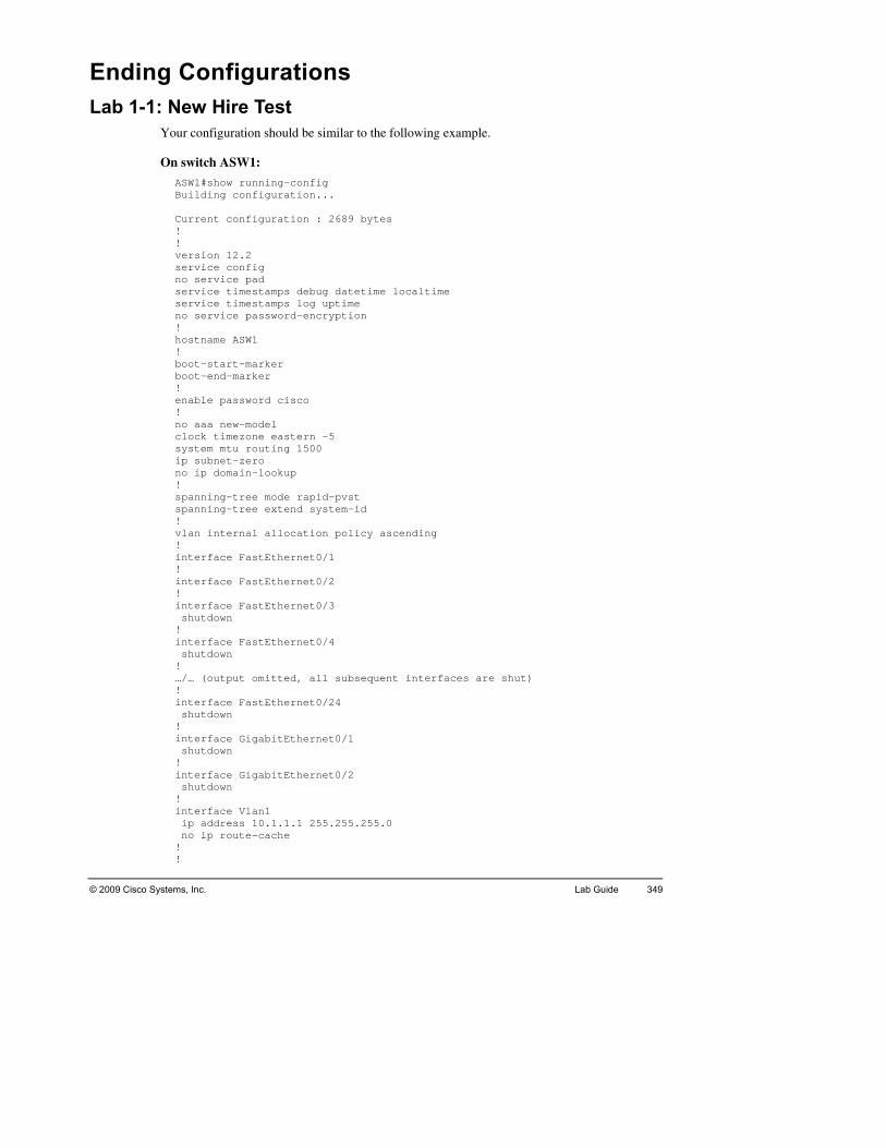
© 2009 Cisco Systems, Inc. Lab Guide 349
ELa
the following example.
On sw
ASW1#show running-config Bui Curren! ! versioservicno serservic imestamps debug datetime localtime servic uptime no ser ption ! hostna! boot-sboot-e! enable! no aaaclock systemip subno ip ! spannispanni id ! vlan i ng ! interf! interf! interf shutd! interf shutd! …/… (o erfaces are shut) ! interf shutd! interf shutd! interf shutd! interf ip ad no ip! !
nding Configurations b 1-1: New Hire Test
Your configuration should be similar to
itch ASW1:
lding configuration...
t configuration : 2689 bytes
n 12.2 e config
e pad vice te timestamps log vice password-encry
me ASW1
tart-marker nd-marker
ssword cisco pa
new-model timezone eastern -5 mtu routing 1500 net-zero
ain-lookup dom
ng-tree mode rapid-pvst ng-tree extend system-
nternal allocation policy ascendi
ace FastEthernet0/1
ace FastEthernet0/2
ace FastEthernet0/3 own
ace FastEthernet0/4 own
utput omitted, all subsequent int
ace FastEthernet0/24 own
ace GigabitEthernet0/1 own
ace GigabitEthernet0/2 own
ace Vlan1 dress 10.1.1.1 255.255.255.0
ute-cache ro

350 Implementing Cisco Switched Networks (SWITCH) v1.0 © 2009 Cisco Systems, Inc.
ip deip htip ht! contr! alias gure replace flash:/switch/lab2-2.cfg force alias figure replace flash:/ switch/lab_3_2_A.cfg force aliasaliasaliasalias! line loggline pass logg logiline pass logi! end
The swit d some of these configuration lines; others were pasted by your inst g of the class. All the items that you configured should be there.
Other S :
Repeswitc
fault-gateway 10.1.1.251 tp server tp secure-server
ol-plane
exec init-2-2 confiec init-3-2-A con ex
exec init-3-2-B configure replace flash:/switch/lab_3_2_B.cfg force exec init-4-2-A configure replace flash:/switch/lab_4_2_A.cfg force exec init-4-2-B configure replace flash:/switch/lab_4_2_B.cfg force exec init-4-2-C configure replace flash:/switch/lab_4_2_C.cfg force
con 0 ing synchronous
0 4 vtyword cisco ing synchronous n vty 5 15 word cisco n
ch automatically generatere the beginninructor befo
witches
at the same process on the other switches, changing the values that are different on each h.

© 2009 Cisco Systems, Inc. Lab Guide 351
LaEt
ould be similar to the following. Only the configuration sections relevant to this
On sw
ASW1! ! interf /1 switc ed vlan 1,3,11,63,65 switc rt mode trunk ! interf switc switc! interf switc switc! interfswitch switc! interfswitch switc
On switc
ASW2#s! ! interf switc 4,66 switc! int switc ed vlan 1,4,12,64,66 switc! interf FastEthernet0/3 switc switc! interfswitch switc! interfswitch switc
b 2-1 Design and Implement VLANs, Trunks, and herChannel
Your configuration shlab are displayed.
itch ASW1:
#sh run
ace FastEthernet0rt trunk allowhpo
hpo
ace FastEthernet0/2 hport trunk allowed vlan 1,3,11,63,65 hport mode trunk
ace FastEthernet0/3 hport access vlan 3 hport mode access
ace FastEthernet0/4 port access vlan 63 hport mode access
ace FastEthernet0/5 t access vlan 11 por
hport mode access
h ASW2:
h run
ace FastEthernet0/1 2,6hport trunk allowed vlan 1,4,1
hport mode trunk
erface FastEthernet0/2hport trunk allow
rt mode trunk hpo
acehport access vlan 4 hport mode access
ace FastEthernet0/4 t access vlan 63 por
hport mode access
ace FastEthernet0/5 port access vlan 11 hport mode access

352 Implementing Cis © 2009 Cisco Systems, Inc. co Switched Networks (SWITCH) v1.0
On swi
DSW1! ! inter e Port-channel31 swit q swit ,12,63-66 swit! inter swit t1q swit ,11,12,63-66 swit shut! inter swit t1q swit allowed vlan 1,3,4,11,12,63-66 swit runk chan! inter swit swit swit chan! inter swit swit swit shut chan! inter swit swit swit shut chan! inter swit swit swit shut! inter swit swit swit! inter swit swit swit! inter rnet0/8 switc swit! interswitc swit ,4,11,12,63-66 swit! !
tch DSW1:
#sh run
facchport trunk encapsulation dot1chport trunk allowed vlan 1,3,4,11chport mode trunk
face Port-channel32 ort trunk encapsulation dochp
chport trunk allowed vlan 1,3,4chport mode trunk down
face FastEthernet0/1 chport trunk encapsulation dochport trunk
ort mode tchpnel-group 31 mode passive
face FastEthernet0/2 chport trunk encapsulation dot1q
,4,11,12,63-66 chport trunk allowed vlan 1,3chport mode trunk
-group 31 mode passive nel
face FastEthernet0/3 chport trunk encapsulation dot1q chport trunk allowed vlan 1,3,4,11,12,63-66 chport mode trunk down
-group 32 mode passive nel
face FastEthernet0/4 chport trunk encapsulation dot1q chport trunk allowed vlan 1,3,4,11,12,63-66 chport mode trunk down
mode passive nel-group 32
face FastEthernet0/5 chport trunk encapsulation dot1q chport trunk allowed vlan 1,3,4,11,12,63-66 chport mode trunk down
face FastEthernet0/6 chport trunk encapsulation dot1q chport trunk allowed vlan 1,3,11,63,65
ort mode trunk chp
face FastEthernet0/7 chport trunk encapsulation dot1q
,12,64,66 chport trunk allowed vlan 1,4chport mode trunk
face FastEthehport access vlan 65 chport mode access
face FastEthernet0/9 1q hport trunk encapsulation dot
ort trunk allowed vlan 1,3chpchport mode trunk

© 2009 Cisco Systems, Inc. Lab Guide 353
On swi
DSW2! ! interf Port-channel31 switc switc 12,63-66 switc shutd! interf switc apsulation dot1q switc owed vlan 1,3,4,11,12,63-66 switc! interf switc switc 4,11,12,63-66 switc chann! interf switc switc switc chann! interf switc switc switc shutd chann! interf switc switc switc shutd chann! interf switc switc switc shutd! interf switc switc switc! interf switc switc switc! interf t0/8 switch switc! interfswitch switc 4,11,12,63-66 switc
tch DSW2:
#sh run
acehport trunk encapsulation dot1qhport trunk allowed vlan 1,3,4,11,hport mode trunk own
ace Port-channehport trunk enc
rt trunk all
l32
hpohport mode trunk
ace FastEthernet0/1 hport trunk encapsulation dot1q hport trunk allowed vlan 1,3,
rt mode trunk hpoel-group 32 mode passive
ace FastEthernet0/2 hport trunk encapsulation dot1q
4,11,12,63-66 hport trunk allowed vlan 1,3,hport mode trunk
group 32 mode passive el-
ace FastEthernet0/3 hport trunk encapsulation dot1q hport trunk allowed vlan 1,3,4,11,12,63-66 hport mode trunk own
group 31 mode passive el-
ace FastEthernet0/4 hport trunk encapsulation dot1q hport trunk allowed vlan 1,3,4,11,12,63-66 hport mode trunk own
e passive el-group 31 mod
ace FastEthernet0/5 hport trunk encapsulation dot1q hport trunk allowed vlan 1,3,4,11,12,63-66 hport mode trunk own
ace FastEthernet0/6 hport trunk encapsulation dot1q hport trunk allowed vlan 1,4,12,64,66
rt mode trunk hpo
ace FastEthernet0/7 hport trunk encapsulation dot1q
11,63,65 hport trunk allowed vlan 1,3,hport mode trunk
ace FastEtherneport access vlan 66 hport mode access
ace FastEthernet0/9 q port trunk encapsulation dot1
rt trunk allowed vlan 1,3,hpohport mode trunk

354 Implementing Cis © 2009 Cisco Systems, Inc. co Switched Networks (SWITCH) v1.0
On swi
CSW1! inter 31 swit swit swit! inter swit t1q swit ,12,63-66 swit shut! inter swit t1q swit allowed vlan 1,3,4,11,12,63-66 swit ort mode trunk ! inter swit swit swit chan! inter swit swit swit chan! inter swit swit swit shut chan! inter swit swit swit shut chan! inter shut! inter shut! inter swit t1q swit 63-66 swit chan! inter swit capsulation dot1q swit 1,12,63-66 swit chan! inter swit swit swit
tch CSW1:
#sh run
face Port-channelchport trunk encapsulation dot1q chport trunk allowed vlan 1,3,4,11,12,63-66 chport mode trunk
face Port-channel32 ort trunk encapsulation dochp
chport trunk allowed vlan 1,3,4,11chport mode trunk down
face Port-channel33 encapsulation dochport trunk
chport trunk chp
face FastEthernet0/1 chport trunk encapsulation dot1q
,4,11,12,63-66 chport trunk allowed vlan 1,3chport mode trunk
-group 31 mode active nel
face FastEthernet0/2 chport trunk encapsulation dot1q chport trunk allowed vlan 1,3,4,11,12,63-66 chport mode trunk nel-group 31 mode active
face FastEthernet0/3 chport trunk encapsulation dot1q chport trunk allowed vlan 1,3,4,11,12,63-66 chport mode trunk down nel-group 32 mode active
face FastEthernet0/4 chport trunk encapsulation dot1q chport trunk allowed vlan 1,3,4,11,12,63-66 chport mode trunk down
mode active nel-group 32
face FastEthernet0/5 n dow
face FastEthernet0/6 down
face FastEthernet0/7 encapsulation dochport trunk
chport trunk allowed vlan 1,3,4,11,12,ort mode trunk chp
nel-group 33 mode on
net0/8 face FastEtherort trunk enchp
chport trunk allowed vlan 1,3,4,1chport mode trunk
mode on nel-group 33
face FastEthernet0/9 chport trunk encapsulation dot1q chport trunk allowed vlan 1,3,4,11,12,63-66 chport mode trunk

© 2009 Cisco Systems, Inc. Lab Guide 355
chann! interf switc switc switc chann! interf switc switc 12,63-66 switc! interf switc switc 4,11,12,63-66 switc! interf shutd
On switc
CSW2# ! ! int 1 swit apsulation dot1q swit owed vlan 1,3,4,11,12,63-66 swit rt mode trunk shut ! inter swit swit swit! inter swit ncapsulation dot1q swit 11,12,63-66 swit! inter swit swit ,4,11,12,63-66 swit chan! inter swit swit ,4,11,12,63-66 swit chan! inter swit swit 63-66 swit shut chan! inter swit
el-group 33 mode on
FastEthernet0/10 acehport trunk encapsulation dot1q hport trunk allowed vlan 1,3,4,11,12,63-66 hport mode trunk el-group 33 mode on
ace FastEthernet0/11 rt trunk encapsulation dot1q hpo
hport trunk allowed vlan 1,3,4,11,hport mode trunk
ace FastEthernet0/12 1q hport trunk encapsulation dot
rt trunk allowed vlan 1,3,hpohport mode trunk
ace FastEthernet0/13 own
h CSW2:
sh run
erface Port-channel3chport trunk encport trunk allch
chpodown
face Port-channel32 chport trunk encapsulation dot1q chport trunk allowed vlan 1,3,4,11,12,63-66 chport mode trunk
nel33 face Port-chanort trunk echp
chport trunk allowed vlan 1,3,4,chport mode trunk
face FastEthernet0/1 t1q chport trunk encapsulation do
ort trunk allowed vlan 1,3chpchport mode trunk nel-group 32 mode active
face FastEthernet0/2 t1q chport trunk encapsulation do
ort trunk allowed vlan 1,3chpchport mode trunk nel-group 32 mode active
face FastEthernet0/3 t1q chport trunk encapsulation do
chport trunk allowed vlan 1,3,4,11,12,ort mode trunk chp
down nel-group 31 mode active
face FastEthernet0/4 t1q chport trunk encapsulation do

356 Implementing Cisco Switched Networks (SWITCH) v1.0 © 2009 Cisco Systems, Inc.
swit swit shut chan! inter shut! inter shut! inter swit encapsulation dot1q swit wed vlan 1,3,4,11,12,63-66 swit chan! inter swit t1q swit 11,12,63-66 swit chan! inter swit swit swit chan! inter swit swit swit chan! inter swit swit swit! inter swit swit 11,12,63-66 swit!
chport trunk allowed vlan 1,3,4,11,12,63-66 chport mode trunk down
mode active nel-group 31
face FastEthernet0/5 down
rnet0/6 face FastEthewn do
ernet0/7 face FastEth
chport trunk chport trunk allochport mode trunk nel-group 33 mode on
face FastEthernet0/8 chport trunk encapsulation dochport trunk allowed vlan 1,3,4,port mode trunk ch
nel-group 33 mode on
face FastEthernet0/9 chport trunk encapsulation dot1q
3,4,11,12,63-66 chport trunk allowed vlan 1,chport mode trunk l-group 33 mode on ne
face FastEthernet0/10 chport trunk encapsulation dot1q chport trunk allowed vlan 1,3,4,11,12,63-66 chport mode trunk nel-group 33 mode on
e FastEthernet0/11 facchport trunk encapsulation dot1q chport trunk allowed vlan 1,3,4,11,12,63-66 chport mode trunk
face FastEthernet0/12 chport trunk encapsulation dot1qport trunk allowed vlan 1,3,4,ch
chport mode trunk

© 2009 Cisco Systems, Inc. Lab Guide 357
La configuration sections relevant
to this
Route
IntEnc q 51 Ip add 55.0
Router R
InterfIp aNo
Switch C
Vlan 5! vlan 5 p ry pr ation 51 vlan 5 name priv! InterfSwitch! InterfSwitchSwitchNo shu
b 2-3 Implement Private VLANs Your configuration should be similar to the following. Only the
lab are displayed.
r R1:
erface f0/0.51 apsulation dot1
ress 10.1.51.1 255.255.2
2:
ace f0/1 51.2 255.255.255.0 ddress 10.1.
shutdown
SW1:
1,501
01 rivate-vlan primaivate-vlan associ
1 TestIsolatedate-vlan isolated
ace f0/11 rt trunk allowed vlan add 51 po
ace f0/12 port mode access port access vlan 51
wn tdo

358 Implementing Cis © 2009 Cisco Systems, Inc. co Switched Networks (SWITCH) v1.0
LEn
in s lation dot1q swit inter swit swit chan inter swit swit chan
On switc
inter swit swit in switc q swit chan inter swit swit chan
On switc
inter swit swit inter swit swit c on inter swit swit chan
On switc
inter swit swit inter swit swit chan inter s lation dot1q s chan
ab 3-1: Implement Multiple Spanning Tree ding Configurations for Task 1:
On switch DSW1:
terface Port-channel32 witchport trunk encapsu
chport mode trunk
face FastEthernet0/3 chport trunk encapsulation doport mode trunk
t1q chnel-group 32 mode on
face FastEthernet0/4 chport trunk encapsulation dot1q chport mode trunk l-group 32 mode on ne
h CSW2:
face Port-channel32 chport trunk encapsulation dot1q chport mode trunk
terface FastEthernet0/3hport trunk encapsulation dot1chport mode trunk nel-group 32 mode on
face FastEthernet0/4 chport trunk encapsulation dot1q chport mode trunk nel-group 32 mode on
h DSW2:
ce Port-channel32 fachport trunk encapsulation dot1q chport mode trunk
face FastEthernet0/3 chport trunk encapsulation dot1q chport mode trunk
hannel-group 32 mode
face FastEthernet0/4 chport trunk encapsulation dot1q chport mode trunk nel-group 32 mode on
h CSW2:
face Port-channel32 t1q chport trunk encapsulation do
chport mode trunk
face FastEthernet0/3 chport trunk encapsulation dot1q chport mode trunk nel-group 32 mode on
face FastEthernet0/4 witchport trunk encapsuwitchport mode trunk
nel-group 32 mode on

© 2009 Cisco Systems, Inc. 359 Lab Guide
End
! spanni tree mode mst spanni! spanni name revis insta insta 4, 66 ! spannispanni DSW1#s MST0 Span Root 8680 This bridge is the root Hello Time 2 sec Max Age 20 sec Forward Delay 15 sec Brid d-ext 0) Delay 15 sec Interf------Fa0/5 Fa0/6 Fa0/7 Po31 Po32 MST1 Span Root Brid ID Priority 24577 (priority 24576 sys-id-ext 1) 001f.2721.8680 ime 2 sec Max Age 20 sec Forward Delay 15 sec Interf------ ------------------ Fa0/5 Fa0/6 Fa0/7 Po31 Po32
ing Configurations for MST MSTP on switch DSW1:
ng-ng-tree extend system-id
ng-tree mst configuration ion1 reg
ion 1 , 63, 65 nce 1 vlan 1, 3, 11
nce 2 vlan 4, 12, 6
ng-tree mst 0-1 priority 24576 ng-tree mst 2 priority 28672
ho spanning-tree
ning tree enabled protocol mstp ID Priority 24576 Address 001f.2721.
ge ID Priority 24576 (priority 24576 sys-i Address 001f.2721.8680
ward Hello Time 2 sec Max Age 20 sec For
ace Role Sts Cost Prio.Nbr Type ----------- ---- --- --------- -------- ---------------------- --
Desg FWD 200000 128.7 P2p Desg FWD 200000 128.8 P2p Desg FWD 200000 128.9 P2p Desg FWD 100000 128.296 P2p Desg FWD 100000 128.304 P2p
ning tree enabled protocol mstp ID Priority 24577 Address 001f.2721.8680 This bridge is the root Hello Time 2 sec Max Age 20 sec Forward Delay 15 sec
ge Address
Hello T
ace Role Sts Cost Prio.Nbr Type ------------------- ---- --- --------- --------
Desg FWD 200000 128.7 P2p Desg FWD 200000 128.8 P2p
Desg FWD 200000 128.9 P2p Desg FWD 100000 128.296 P2p Desg FWD 100000 128.304 P2p

360 Implementing Cis Inc. co Switched Networks (SWITCH) v1.0 © 2009 Cisco Systems,
MST2 Spa Roo y 15 sec Bri Inter-----Fa0/5Fa0/6Fa0/7Po31 Po32 DSW1#
MST on
! spann mode mst spann extend system-id ! sp ion n revi n 1 inst inst! spannspann DSW2# MST0 Spa Roo Forward Delay 15 sec Bri iority 28672 sys-id-ext 0) Address 001f.2721.8600 ard Delay 15 sec Inter----- ------------------- Fa0/5Fa0/6Fa0/7Po31 Po32
nning tree enabled protocol mstp t ID Priority 24578 Address 001f.2721.8600 Cost 200000 Port 7 (FastEthernet0/5) Hello Time 2 sec Max Age 20 sec Forward Dela
dge ID Priority 28674 (priority 28672 sys-id-ext 2) Address 001f.2721.8680
Hello Time 2 sec Max Age 20 sec Forward Delay 15 sec
face Role Sts Cost Prio.Nbr Type -------------- ---- --- --------- -------- ------------------------- Root FWD 200000 128.7 P2p
Desg FWD 200000 128.8 P2p Desg FWD 200000 128.9 P2p Desg FWD 100000 128.296 P2p Altn BLK 100000 128.304 P2p
switch DSW2:
ing-treeing-tree
anning-tree mst configuratame region1
sioance 1 vlan 1, 3, 11, 63, 65 ance 2 vlan 4, 12, 64, 66
-tree mst 0-1 priority 28672 inging-tree mst 2 priority 24576
sho spanning-tree
nning tree enabled protocol mstp D Priority 24576 t I
Address 001f.2721.8680 Cost 0 Port 7 (FastEthernet0/5) Hello Time 2 sec Max Age 20 sec
dge ID Priority 28672 (pr Hello Time 2 sec Max Age 20 sec Forw
Nbr Type face Role Sts Cost Prio.-------------- ---- --- --------- -------- -------
8.7 P2p Root FWD 200000 12 Desg FWD 200000 128.8 P2p Desg FWD 200000 128.9 P2p Altn BLK 100000 128.296 P2p Altn BLK 100000 128.304 P2p

© 2009 Cisco Systems, Inc. Lab Guide 361
MST1 Span Root 15 sec Brid Interf------Fa0/5 Fa0/6 Fa0/7 Po31 Po32 MST2 Span Root Address 001f.2721.8600 idge is the root ime 2 sec Max Age 20 sec Forward Delay 15 sec Brid d-ext 2) Delay 15 sec Interf------Fa0/5 Fa0/6 Fa0/7 Po31 Po32 DSW2#
MST on
spannispanni! spanni name revis n 1 insta an 1, 3, 11, 63, 65 insta an 4, 12, 64, 66
ning tree enabled protocol mstp ID Priority 24577 Address 001f.2721.8680 Cost 200000 Port 7 (FastEthernet0/5) Hello Time 2 sec Max Age 20 sec Forward Delay
ge ID Priority 28673 (priority 28672 sys-id-ext 1) Address 001f.2721.8600
Hello Time 2 sec Max Age 20 sec Forward Delay 15 sec
ace Role Sts Cost Prio.Nbr Type ------------- ---- --- --------- -------- ------------------------- Root FWD 200000 128.7 P2p
Desg FWD 200000 128.8 P2p Desg FWD 200000 128.9 P2p Altn BLK 100000 128.296 P2p Altn BLK 100000 128.304 P2p
ning tree enabled protocol mstp D Priority 24578 I
This br
Hello T
ge ID Priority 24578 (priority 24576 sys-i Address 001f.2721.8600 Hello Time 2 sec Max Age 20 sec Forward
ace Role Sts Cost Prio.Nbr Type ------------- ---- --- --------- -------- -------------------------- Desg FWD 200000 128.7 P2p
Desg FWD 200000 128.8 P2p Desg FWD 200000 128.9 P2p Desg FWD 100000 128.296 P2p Desg FWD 100000 128.304 P2p
switches ASW1, ASW2, CSW1, and CSW2:
ng-tree mode mst ng-tree extend system-id
ng-tree mst configuration gion1 re
ionce 1 vlnce 2 vl

362 Implementing Cisco Switched Networks (SWITCH) v1.0 © 2009 Cisco Systems, Inc.
L
span
Lab 4-1: Im g
i ip de
On switc
ip ro in n ip a .0 255.255.255.254 inter no s ip a 54 inter no s no ichann! inter no s no i chan! inter no s ip a! inter ip a 5.255.0 ! inter ip a ! route no a netw
ab 3-2: Implement PVRST+ PVRST+ on all switches on your pod
ning-tree mode rapid-pvst
plement Inter-VLAN RoutinOn switches ASW1 and ASW2:
interface Vlan3 p address 10.1.3.10 255.255.255.0
fault-gateway 10.1.3.1
hes DSW1 and DSW2:
uting
terface Port-channel31 o switchport
ddress 10.1.253
face Port-channel32 witchport
55.255.255.2ddress 10.1.253.2 2
face range FastEthernet0/1-2 witchport p address
ssive el-group 31 mode pa
face range FastEthernet0/3-4 witchport p address
assive nel-group 32 mode p
face FastEthernet0/5 chport wit
ddress 10.1.253.4 255.255.255.254
face Vlan4 ddress 10.1.4.1 255.25
facddr
e Vlan11 ess 10.1.11.1 255.255.255.0
r eigrp 10 uto-summary
10.1.0.0 0.0.255.255 ork
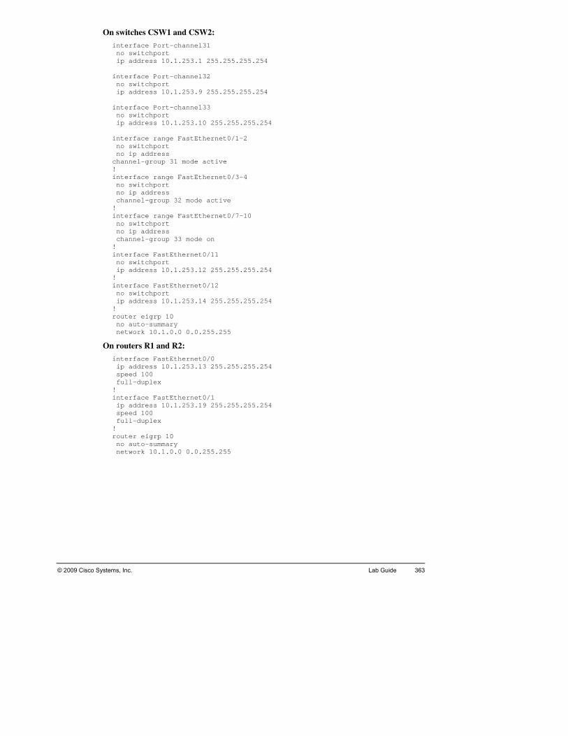
© 2009 Cisco Systems, Inc. Lab Guide 363
On swi
inte no sw ip ad interf no sw ip ad interf no sw ip ad 54 interf no sw no ipchanne! interf no sw no ip chann! interf no sw no ip chann! interf no sw ip ad! interf no sw ip ad! router no au netwo
On route
interf ip ad speed full-! interf ip ad speed fu! router no au netwo
tches CSW1 and CSW2:
rface Port-channel31 itchport
5.255.255.254 dress 10.1.253.1 25
ace Port-channel32 chport it
dress 10.1.253.9 255.255.255.254
ace Port-channel33 chport it
dress 10.1.253.10 255.255.255.2
net0/1-2 ace range FastEtheritchport ddress a
l-group 31 mode active
net0/3-4 ace range FastEtheritchport address
group 32 mode active el-
ace range FastEthernet0/7-10 itchport address el-group 33 mode on
FastEthernet0/11 aceitchport
55.255.255.254 dress 10.1.253.12 2
ace FastEthernet0/12 itchport
ss 10.1.253.14 255.255.255.254 dre
eigrp 10 to-summary rk 10.1.0.0 0.0.255.255
rs R1 and R2:
ace FastEthernet0/0 dress 10.1.253.13 255.255.255.254
0 10duplex
ace FastEthernet0/1 dress 10.1.253.19 255.255.255.254 100
ll-duplex
eigrp 10 to-summary
0.255.255 rk 10.1.0.0 0.

364 Implementing Cis © 2009 Cisco Systems, Inc. co Switched Networks (SWITCH) v1.0
LN
ip iip sl life forever start-time now loggiloggisnmp-snmp-snmp-snmp-snmp-
On switc
loggiloggisnmpsn 00 traps ciscor snmp ps config snmp- -membership snmp-
Lab 6-1: ImplOn switc
inter ip a
s nnel31 20 s nnel32 20 inter ip a stan stan
On switc
inter ip a stan stan inter ip a stan sta s stand nnel31 20 stan el32 20 end
ab 5-1: Implementing High Availability and Reporting in a etwork Design
On switch CSW1:
sla 1 cmp-echo 10.1.3.10
a schedule 1ng 10.1.3.50 ng trap informational server community ciscor ro
aps ciscor server host 10.1.3.50 trserver enable traps config server enable traps vlan-membership server enable traps errdisable
h DSW2:
ng 10.1.4.100 ng trap informational server community ciscor ro -
mp-server host 10.1.4.1-server enable traserver enable traps vlanserver enable traps errdisable
ement and Tune HSRP h DSW1:
face Vlan3 ddress 10.1.3.3 255.255.255.0
standby 3 ip 10.1.3.1 standby 3 priority 120 standby 3 preempt tandby 3 track Port-chatandby 3 track Port-cha
face Vlan4 ddress 10.1.4.3 255.255.255.0 dby 4 ip 10.1.4.1 dby 4 preempt
h DSW2:
face Vlan3 ddress 10.1.3.2 255.255.255.0 y 3 ip 10.1.3.1 db
dby 3 preempt
face Vlan4 ddress 10.1.4.2 255.255.255.0dby 4 ip 10.1.4.1
0 ndby 4 priority 12tandby 4 preempt
by 4 track Port-chadby 4 track Port-chann

© 2009 Cisco Systems, Inc. Lab Guide 365
La
int 1 switch switc interf switc switc interf ip ad
On switc
interf switc sw 0 interf switc switc interf ip ad
On route
interf ip ad 255.255.248 duple speed vrrp vr interf ip ad duple speed vrrp end FastEt Stat Virt Virt Adve Pree Prio Mast al), priority is 150 Mast 1.000 sec Mast terval is 3.414 sec FastEt Stat Virt Virt Adve Pree Prio Mast ority is 150 Mast Mast
b 6-2: Implementing VRRP On switch CSW1:
erface FastEthernet0/1port mode access hport access vlan 10
ace FastEthernet0/12 ort mode access hp
hport access vlan 10
ace Vlan10 dress 10.1.253.25 255.255.255.248
SW2: h C
ace FastEthernet0/11 hport mode access
itchport access vlan 2
ace FastEthernet0/12 hport mode access hport access vlan 20
ace Vlan20 dress 10.1.253.33 255.255.255.248
r R1:
ace FastEthernet0/0 dress 10.1.253.27 255.x auto auto 1 ip 10.1.253.30
rp 1 priority 150
ace FastEthernet0/1 dress 10.1.253.36 255.255.255.248 x auto auto
4 2 ip 10.1.253.3
hee rnet0/0 - Group 1 is Master
ual IP address is 10.1.253.30 ual MAC address is 0000.5e00.0101
al is 1.000 sec rtisement intervmption enabled rity is 150 er Router is 10.1.253.27 (loc
vertisement interval is er Ad Down iner
hernet0/1 - Group 2 e is Backup ual IP address is 10.1.253.34 ual MAC address is 0000.5e00.0102 rtisement interval is 1.000 sec mption enabled rity is 100
, prier Router is 10.1.253.35er Advertisement interval is 1.000 sec er Down interval is 3.609 sec (expires in 3.389 sec)

366 Implementing Cis ems, Inc. co Switched Networks (SWITCH) v1.0 © 2009 Cisco Syst
On ro
inte et0/0 ip a 8 dupl spee vrrp vrrp inter ip a 255.248 dupl spee vrrp show FastE Sta is Backup Vir al IP address is 10.1.253.30 Vir s is 0000.5e00.0101 Adv Pre Pri Mas Mas Mas ec) FastE Sta Vir Virt Adv Pre Pri Mas priority is 150 Mas sec Mas
Lab 7-1: Secu ecurity Attacks On switc
ip dhip dh
in net0/1 - 2 i inter swit swit iolation restrict swit ac-address 0050.5684.3a29
On switc
ault ip d ip d
uter R2:
rface FastEthernddress 10.1.253.35 255.255.255.24ex auto d auto 2 ip 10.1.253.34 2 priority 150
face FastEthernet0/1 ress 10.1.253.26 255.255.dd
ex auto d auto 1 ip 10.1.253.30
vrrp thernet0/1 - Group 1 tetutual MAC addresertisement interval is 1.000 sec emption enabled ority is 100 ter Router is 10.1.253.27, priority is 150 ter Advertisement interval is 1.000 sec
7 ster Down interval is 3.609 sec (expires in 3.21
thernet0/0 - Group 2 te is Master tual IP address is 10.1.253.34 ual MAC address is 0000.5e00.0102 ertisement interval is 1.000 sec ption enabled em
ority is 150 ter Router is 10.1.253.35 (local),
l is 1.000ter Advertisement intervater Down interval is 3.414 sec
re Network Switches to Mitigate Sh ASW1:
spanning-tree portfast bpduguard default spanning-tree loopguard default
cp snooping cp snooping vlan 1-4094
ip arp inspection vlan 1-4094 terface range FastEtherp dhcp snooping trust
face FastEthernet0/3 chport port-security chport port-security vchport port-security m
h ASW2:
spanning-tree portfast bpduguard def spanning-tree loopguard default
hcp snooping p snooping vlan 1-4094 hc

© 2009 Cisco Systems, Inc. Lab Guide 367
ip ar inter switchswitch
On switc
ip access-list extended NOTEL telnet ac ac t bpduguard default in
On switc
pe ac match ip address NOTEL p TEST 20 lt int
p inspection vlan 1-4094
ce range FastEthernet0/1 - 2 fa ip dhcp snooping trust
FastEthernet0/3 interfaceport port-security port port-security mac-address sticky
h DSW1:
permit tcp any any eq
vlan access-map TEST 10 tion drop match ip address NOTEL
vlan access-map TEST 20 tion forward
vlan filter TEST vlan-list 2-3 ip arp inspection vlan 1-4094
spanning-tree portfas spanning-tree loopguard default
interface FastEthernet0/5 spanning-tree guard root ip arp inspection trust
terface range FastEthernet0/6 - 7 ip arp inspection trust
h DSW2:
ip access-list extended NOTEL it tcp any any eq telnet rm
vlan access-map TEST 10 on drop ti
vlan access-ma
action forward
vlan filter TEST vlan-list 2-3 spanning-tree portfast bpduguard defau
spanning-tree loopguard default
vlan 1-4094 ip arp inspection
interface FastEthernet0/5 t spanning-tree guard roo
p arp inspection trust i
erface range FastEthernet0/6 - 7 nspection trust ip arp i

368 Implementing Cisco Switched Networks (SWITCH) v1.0 © 2009 Cisco Systems, Inc.
LC
SW2:
inswswitc 2,63-66 srr-qpriormls qauto interswitcswitc 3,4,11,12,63-66 srr-q 20 priormls qauto interswitcswitcswitcswitc ort priority extend trust srr-q ue bandwidth share 10 10 60 20 priormls qmls qauto servi interswitcswitcswitcswitcsrr-qpriormls qmls qauto servi coPhone
ab 8-1: Plan Implementation and Verification of VoIP in a ampus Network
On switches ASW1 and A
terface FastEthernet0/1 itchport mode trunk
hport trunk allowed vlan 3,4,11,160 20 ueue bandwidth share 10 10
ity-queue out os trust dscp qos voip trust
face FastEthernet0/2 hport mode trunk hport trunk allowed vlan ue bandwidth share 10 10 60ue
ity-queue out os trust dscp qos voip trust
face FastEthernet0/14 hport mode access hport access vlan 3 ort voice vlan 63 hp
hpueity-queue out os trust device cisco-phone os trust cos qos voip cisco-phone ce-policy input AutoQoS-Police-CiscoPhone
face FastEthernet0/15 hport mode access hport access vlan 3 hport voice vlan 63
rust hport priority extend tueue bandwidth share 10 10 60 20 ity-queue out trust device cisco-phone os
os trust cos qos voip cisco-phone
e-Cisce-policy input AutoQoS-Polic

© 2009 Cisco Systems, Inc. Lab Guide 369
On switch DSW1:
ip 10.1.63.1 10.1.63.49 ip dhcip dhcip dhcip dhcnetwordefauloptionlease ip dhcnetwordefauloption 4.12 lease interfswitchswitch allowed vlan 3,4,11,12,63-66 srr-qu e bandwidth share 10 10 60 20 priorimls qoauto q interfswitchswitch 3,4,11,12,63-66 srr-qu 0 60 20 priorimls qoauto q interfswitchswitchsrr-qupriorimls qoauto q interfswitchswitchsrr-qupriorimls qoauto qno shu interfip addstandbstandbstandbstandbstandbinterfip add 5.0 standbstandb y 120 standb pt standb 1 30 standb
dhcp excluded-address p excluded-address 10.1.63.100 10.1.63.255 p excluded-address 10.1.64.1 10.1.64.49 p excluded-address 10.1.64.100 10.1.64.255 p pool vlan63 k 10.1.63.0 255.255.255.0 t-router 10.1.63.1 150 ip 10.1.63.11 10.1.64.12 8 p pool vlan64 k 10.1.64.0 255.255.255.0
0.1.64.1 t-router 1 150 ip 10.1.63.11 10.1.68
ace FastEthernet0/5 trunk port mode
rt trunk poeuty-queue out s trust dscp os voip trust
ace FastEthernet0/6 port mode trunk port trunk allowed vlan eue bandwidth share 10 1ty-queue out trust dscp s
os voip trust
ace FastEthernet0/7 port mode trunk port trunk allowed vlan 3,4,11,12,63-66
0 60 20 eue bandwidth share 10 1ty-queue out s trust dscp os voip trust
ace FastEthernet0/15 port mode access port access vlan 63 eue bandwidth share 10 10 60 20 ty-queue out s trust dscp os voip trust t
e Vlan 63 acress 10.1.63.3 255.255.255.0 y 63 ip 10.1.63.1 y 63 priority 120 y 63 preempt y 63 track Port-channel31 30
2 30 y 63 track Port-channel3ace Vlan 64 ress 10.1.64.3 255.255.25
.1.64.1 y 64 ip 10y 64 priorit64 preemy
y 64 track Port-channel3y 64 track Port-channel32 30

370 Implementing Cis © 2009 Cisco Systems, Inc. co Switched Networks (SWITCH) v1.0
On switch DSW2:
ip .1.63.1 10.1.63.99 ip dhip dhip dhip dhnetwodefauoptioleaseip dhnetwodefauoptio 64.12 lease interswitcswitcsrr-q h share 10 10 60 20 priormls qauto interswitcswitc 3,4,11,12,63-66 srr-q 0 60 20 priormls qauto interswitcswitcsrr-qpriormls qauto interswitcswitcsrr-qpriormls qauto no sh interip adstandstandstandstandstandinterip ad 55.0 standstand y 120 standstand 31 30 stand
dhcp excluded-address 10cp excluded-address 10.1.63.150 10.1.63.255 cp excluded-address 10.1.64.1 10.1.64.99 cp excluded-address 10.1.64.150 10.1.64.255 cp pool vlan63 rk 10.1.63.0 255.255.255.0 lt-router 10.1.63.1 n 150 ip 10.1.63.11 10.1.63.12 8 cp pool vlan64 rk 10.1.64.0 255.255.255.0
10.1.64.1 lt-router n 150 ip 10.1.63.11 10.1. 8
face FastEthernet0/5 hport mode trunk
k allowed vlan 3,4,11,12,63-66 hport trunue bandwidtue
ity-queue out os trust dscp qos voip trust
face FastEthernet0/6 hport mode trunk hport trunk allowed vlanueue bandwidth share 10 1ity-queue out trust dscp os
qos voip trust
face FastEthernet0/7 hport mode trunk hport trunk allowed vlan 3,4,11,12,63-66
10 60 20 ueue bandwidth share 10 ity-queue out os trust dscp qos voip trust
face FastEthernet0/15 hport mode access hport access vlan 63 ueue bandwidth share 10 10 60 20 ity-queue out os trust dscp qos voip trust ut
ce Vlan 63 fadress 10.1.63.2 255.255.255.0 by 63 ip 10.1.63.1 by 63 priority 120 by 63 preempt by 63 track Port-channel31 30
32 30 by 63 track Port-channelface Vlan 64 dress 10.1.64.2 255.255.2
0.1.64.1 by 64 ip 1 64 prioritby
by 64 preempt by 64 track Port-channelby 64 track Port-channel32 30

© 2009 Cisco Systems, Inc. Lab Guide 371
On switches CSW1 and CSW2:
intno swino ip srr-qu e 10 10 60 20 priorimls qoauto qchanne interfno swino ip srr-qupriorimls qoauto qchanne interfno swino ip srr-qupriorimls qoauto qchanne interfno swino ip srr-qu 60 20 priorimls qoauto qchanne
erface FastEthernet0/1 tchport address eue bandwidth sharty-queue out s trust dscp os voip trust l-group 31 mode on
ace FastEthernet0/2 tchport dress ad
eue bandwidth share 10 10 60 20 ty-queue out s trust dscp os voip trust l-group 31 mode on
ace FastEthernet0/3 tchport address eue bandwidth share 10 10 60 20 -queue out ty
s trust dscp os voip trust l-group 32 mode on
ace FastEthernet0/4 tchport address eue bandwidth share 10 10ty-queue out s trust dscp voip trust os
l-group 32 mode on

372 Implementing Cisco Switched Networks (SWITCH) v1.0 © 2009 Cisco Systems, Inc.
L
in rnet0/11 descr swit swit inter desc swit swit inter desc swit swit span mls
On A
inter desc swit 4,63 switc interf rnet0/12 desc swit swit inter desc swit switspann mls
On DSW
mls qinter desc swit swit 11,63 swit chan spa m inter rnet0/12 desc swit swit
ab 9-1 Integrating Wireless in the Campus: On ASW1:
terface FastEtheiption AP1 chport trunk allowed vlan 4,63 chport mode trunk
face FastEthernet0/12 ption AP2 ri
chport trunk allowed vlan 4,63 chport mode trunk
face FastEthernet0/13 ription AP3 chport access vlan 11 port mode access ch
ning-tree portfast qos trust dscp
SW2:
face FastEthernet0/11 ription AP4 chport trunk allowed vlan
runk hport mode t
ace FastEtheription AP5
vlan 4,63 chport trunk allowed chport mode trunk
face FastEthernet0/13 ption AP6 ri
chport access vlan 11 chport mode access ing-tree portfast qos trust dscp
: 1
os face FastEthernet0/11 ription WLC1
1q chport trunk encapsulation dot,chport trunk allowed vlan 1,4
chport mode trunk nel-group 11 mode on ning-tree portfast trunk n
ls qos trust cos
face FastEtheription WCS1 chport mode access chport access vlan 3

© 2009 Cisco Systems, Inc. Lab Guide 373
On DS
mls qosinterf rnet0/11 descr switc switc switc chann spann mls q interf descr switc switc
W2:
ace FastEtheiption WLC2
ion dot1q hport trunk encapsulathport trunk allowed vlan 1,4,11,63 hport mode trunk el-group 11 mode on ing-tree portfast trunk os trust cos
ace FastEthernet0/12 iption WCS2 ort mode access hp
hport access vlan 4

P for each switch, which port connects
to whgenerto dothe la
od Physical Ports Map During the implementation process, you must determine,
ich neighbor. The ports represented on each device connection in the Visual Objective are ic ports. Each port can represent one or several physical interface. Use the following table cument the physical interfaces used in your pod. You will use this information throughout bs:
Phys
ical
por
t in
your
pod
© 2009 Cisco Systems, Inc. All rights reserved. SWITCH v1.0—1
P5
DSW
2
P4
DSW
2
P2R
2P3
DSW
2
P1R
2P
2D
SW2
P2R
1P1
DSW
2
P1R
1P5
DSW
1
P5C
SW2
P4
DSW
1
P4C
SW2
P3D
SW1
P3C
SW2
P2D
SW1
P2C
SW2
P1
DSW
1
P1C
SW2
P3AS
W2
P5C
SW1
P2AS
W2
P4C
SW1
P1
ASW
2
P3C
SW1
P3AS
W1
P2C
SW1
P2
ASW
1
P1C
SW1
P1AS
W1
Port
Nam
e on
the
map
Dev
ice
Phys
ical
por
t in
your
pod
Port
Nam
e on
the
map
Dev
ice
374 Implementing Cisco Switched Networks (SWITCH) v1.0 © 2009 Cisco Systems, Inc.
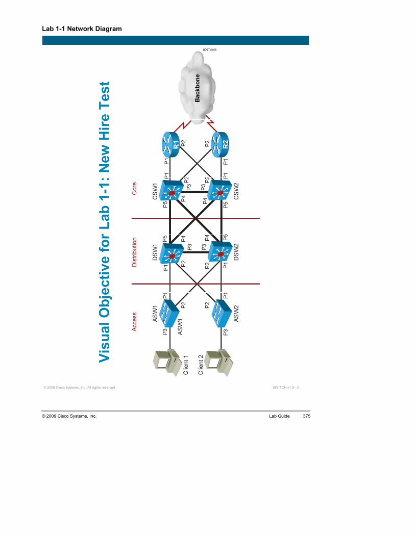
Lab 1-1 Network Diagram
© 2009 Cisco Systems, Inc. All rights reserved. SWITCH v1.0—2
Visu
al O
bjec
tive
for L
ab 1
-1: N
ew H
ire T
est
© 2009 Cisco Systems, Inc. Lab Guide 375
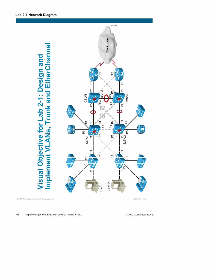
Lab 2-1 Network Diagram
© 2009 Cisco Systems, Inc. All rights reserved. SWITCH v1.0—3
Visu
al O
bjec
tive
for L
ab 2
-1: D
esig
n an
d Im
plem
ent V
LAN
s, T
runk
and
Eth
erC
hann
el
376 Implementing Cisco Switched Networks (SWITCH) v1.0 © 2009 Cisco Systems, Inc.

Lab 2-2 Network Diagram
© 2009 Cisco Systems, Inc. All rights reserved. SWITCH v1.0—4
Visu
al O
bjec
tive
for L
ab 2
-2: T
roub
lesh
oot
Com
mon
VLA
N C
onfig
urat
ion
and
Secu
rity
Issu
es
© 2009 Cisco Systems, Inc. Lab Guide 377

Lab 2-3 Network Diagram
© 2009 Cisco Systems, Inc. All rights reserved. SWITCH v1.0—5
Visu
al O
bjec
tive
for L
ab 2
-3: C
onfig
ure
Priv
ate
VLA
Ns
378 Implementing Cisco Switched Networks (SWITCH) v1.0 © 2009 Cisco Systems, Inc.

Lab 3-1 Network Diagram
© 2009 Cisco Systems, Inc. All rights reserved. SWITCH v1.0—6
Visu
al O
bjec
tive
for L
ab 3
-1: I
mpl
emen
t M
ultip
le S
pann
ing
Tree
© 2009 Cisco Systems, Inc. Lab Guide 379

Lab 3-2 Network Diagram
© 2009 Cisco Systems, Inc. All rights reserved. SWITCH v1.0—7
Visu
al O
bjec
tive
for L
ab 3
-2: I
mpl
emen
t PV
RST
+
380 Implementing Cisco Switched Networks (SWITCH) v1.0 © 2009 Cisco Systems, Inc.
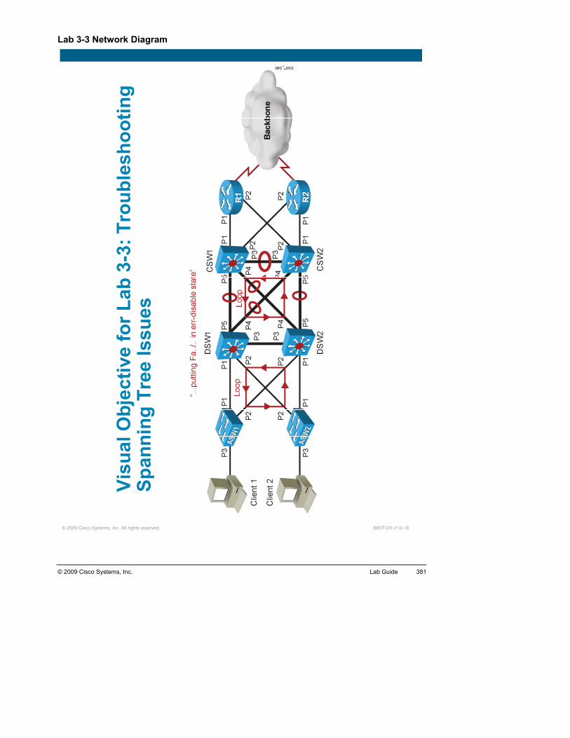
Lab 3-3 Network Diagram
© 2009 Cisco Systems, Inc. All rights reserved. SWITCH v1.0—8
Visu
al O
bjec
tive
for L
ab 3
-3: T
roub
lesh
ootin
g Sp
anni
ng T
ree
Issu
es
© 2009 Cisco Systems, Inc. Lab Guide 381
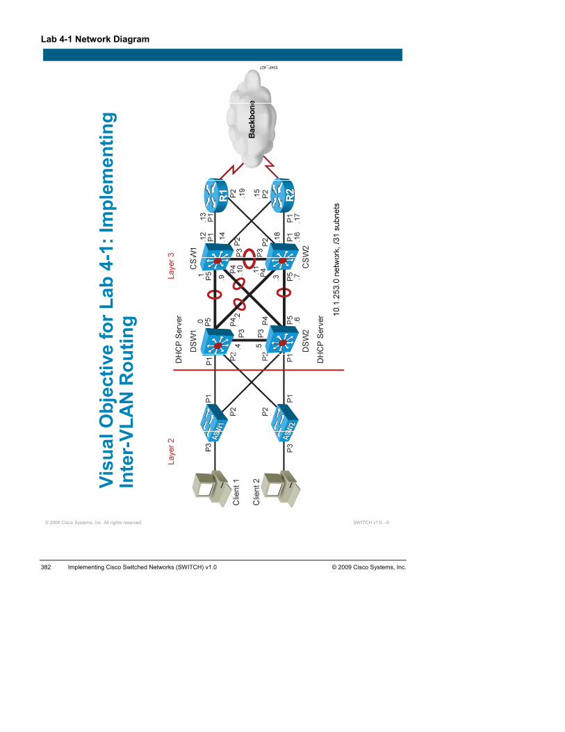
Lab 4-1 Network Diagram
© 2009 Cisco Systems, Inc. All rights reserved. SWITCH v1.0—9
Visu
al O
bjec
tive
for L
ab 4
-1: I
mpl
emen
ting
Inte
r-VL
AN
Rou
ting
382 Implementing Cisco Switched Networks (SWITCH) v1.0 © 2009 Cisco Systems, Inc.

Lab 5-1 Network Diagram
© 2009 Cisco Systems, Inc. All rights reserved. SWITCH v1.0—11
Visu
al O
bjec
tive
for L
ab 5
-1: I
mpl
emen
t HA
in
a N
etw
ork
Des
ign
© 2009 Cisco Systems, Inc. Lab Guide 383

Lab 6-1 Network Diagram
© 2009 Cisco Systems, Inc. All rights reserved. SWITCH v1.0—12
Visu
al O
bjec
tive
for L
ab 6
-1: I
mpl
emen
t and
Tu
ne H
SRP
384 Implementing Cisco Switched Networks (SWITCH) v1.0 © 2009 Cisco Systems, Inc.

Lab 6-2 Network Diagram
© 2009 Cisco Systems, Inc. All rights reserved. SWITCH v1.0—13
Visu
al O
bjec
tive
for L
ab 6
-2: I
mpl
emen
ting
VRR
P
© 2009 Cisco Systems, Inc. Lab Guide 385

Lab 7-1 Network Diagram
© 2009 Cisco Systems, Inc. All rights reserved. SWITCH v1.0—14
Visu
al O
bjec
tive
for L
ab 7
-1: S
ecur
e N
etw
ork
Switc
hes
to M
itiga
te S
ecur
ity A
ttack
s
386 Implementing Cisco Switched Networks (SWITCH) v1.0 © 2009 Cisco Systems, Inc.

Lab 8-1 Network Diagram
© 2009 Cisco Systems, Inc. All rights reserved. SWITCH v1.0—15
Visu
al O
bjec
tive
for L
ab 8
-1: P
lan
Impl
emen
tatio
n of
VoI
P in
a C
ampu
s N
etw
ork
© 2009 Cisco Systems, Inc. Lab Guide 387

388 Implementing Cisco Switched Networks (SWITCH) v1.0 © 2009 Cisco Systems, Inc.

Lab 9-1 Network Diagram
© 2009 Cisco Systems, Inc. All rights reserved. SWITCH v1.0—16
Visu
al O
bjec
tive
for L
ab 9
-1: I
nteg
ratin
g W
irele
ss in
the
Cam
pus
© 2009 Cisco Systems, Inc. Lab Guide 389

390 Implementing Cisco Switched Networks (SWITCH) v1.0 © 2009 Cisco Systems, Inc.


