Embed Size (px)
Citation preview

Switch off your Mobiles Phonesor
Change Profile to Silent Mode

Conceptual Modelling Concepts
and their Representation

Topics Degree of Relationship Connectivity and Cardinality Relationship Existence Problems with ER Models
Connection Traps Fan Traps Chasm Traps
Many-Many Relationships Generalization Hierarchy ER Model - Example

Relationship Relationship is a set of
associations among Entities. It indicates that there is a business
relationship between these Entity. Examples
Customer places Order Order is placed by Customer Employee works on Project Project has project member
Employee Student Entity is related to Team Entity
type because each Student is a Member of a Team.

Relationship Relationship or Relationship
Instance is an ordered pair consisting of particular related entities, such as (Emanuel Vagas, Phys201F2005A04), where Phys201F2005A04 is Emanuel's Team Number.
Student
TeamMember of

Identify Relationships
Integrity Rules – derived from ER Diagram: Each A must be assigned to one or more
B Each B may be responsible for one or
more A
A BAssign

Identify Relationships
Integrity Rules – derived from ER Diagram: Each patient must be admitted to a
single ward Each ward may be assigned one or more
patients

Degree of a Relationship Degree of a Relationship is number
of Entities associated with relationship.
Most common relationship degrees are Unary Relationship Binary Relationship Ternary Relationship

Unary Relationship
Unary Relationship occurs when an Entity is related to itself.
Relationship between the instances of a single Entity.
They are also called “recursive relationships”
Examples Employee manages employees Some employees are married to
other employees.

Unary Relationship

Binary Relationship Relationship between instances of
two Entities Most commonly encountered Examples
One to one - Warden takes care of one Hostel
One to Many - Hostel contains many Rooms
Many to Many - Students graduating in many Degrees

Binary Relationship

Ternary Relationship Ternary Relationship involves Three
Entities and is used when a binary relationship is inadequate.
A simultaneous relationship among the instances of three Entities
Ternary Relationships is not same as three Binary Relationships
Examples Course or Section, Instructor,
Classroom ---> Timetable

Ternary Relationship All ternary relationships are
represented as associative entities Ternary or N-nary Relationships are
decomposed into two or more binary relationships.

Ternary Relationship

Connectivity and Cardinality Connectivity of a relationship
describes mapping of associated Entity instances in Relationship.
Values of connectivity are One or Many
Cardinality of a Relationship is actual number of related occurrences for each of Two Entities.
Basic types of connectivity for relations are: One to One, One to Many and Many to Many.

CardinalityE1 E2
E1
E1
E2
E2
One to ManyOne to Many
Many to ManyMany to Many
One to OneOne to One
1:1
1:M
M:N

One to One One to One (1:1) relationship is
when at most one instance of a Entity A is associated with one instance of Entity B.
Example Employees in the company are each
assigned their own office. For each employee there exists a unique office and for each office there exists a unique employee.
OFFICEASSIG
NEMPLOYEE

One to Many One to Many (1:M) relationships is
when for one instance of Entity A, there are zero, one, or many instances of Entity B, but for one instance of entity B, there is only one instance of entity A.
Example A department has many employees Each employee is assigned to one
departmentDEPARTMENT HAS EMPLOYEE

Many to Many Many to Many (M:N) relationship,
sometimes called non-specific, is when for one instance of Entity A, there are zero, one, or many instances of Entity B and for one instance of Entity B there are zero, one, or many instances of Entity A.
Many to Many relationships cannot be directly translated to relational tables but instead must be transformed into two or more one-to-many relationships using associative entities.

Many to Many Example
Employees can be assigned to no more than two projects at the same time;
Projects must have assigned at least three employees
A single employee can be assigned to many projects; conversely, a single project can have assigned to it many employees. Here the cardinality for the relationship between employees and projects is two and the cardinality between project and employee is three.

EMPLOYEE ASSIGN PROJECT
Many to Many

Relationship Existence Existence denotes whether the
existence of an Entity instance is dependent upon existence of another, related, entity instance.
Existence of an entity in a relationship is defined as either Mandatory or Optional
If an instance of an entity must always occur for an entity to be included in a relationship, then it is Mandatory.

Relationship Existence An example of Mandatory
existence is the statement "every project must be managed by a single department".
DEPARTMENT MANAGE
PROJECT

Relationship Existence If the instance of the entity is not
required, it is Optional. An example of Optional existence is
the statement, "employees may be assigned to work on project".
EMPLOYEE ASSIGN PROJECT

Problems with ER Models Problems may arise when creating
an ER model. Problems are referred to as
Connection Traps Normally occur due to a
misinterpretation of the meaning of certain relationships (Howe, 1989). Fan Traps Chasm Traps
Fan Traps Model represents a relationship
between entity types, but pathway between certain entity occurrences is ambiguous.
Fan trap may exist where two or more 1:M relationships fan out from the same entity.
Staff BranchDivisionHas Operate
s

Fan Traps

Fan Traps This model represents the facts that
a Single Division operates one or more Branches and Single Division has one or more Staffs.
Problem arises when we want to know which Staff works at a particular Branch.

Fan Traps – Better Structure

Fan Traps – Better Structure This model represents the facts that
a Single Division operates one or more Branches and Single Branch has one or more Staffs.
Division StaffBranchOperates
Has

Chasm Traps Model suggests existence of a
relationship between entity trap types, but pathway does not exist between certain entity occurrences.
Chasm trap may occur where there are one or more relationships with a minimum multiplicity of zero (that is optional participation) forming part of the pathway between related entities.

Chasm Traps This model represents the facts that
a single branch has one or more staff who oversee zero or more properties for rent.
Not all staff oversee property, and not all properties are overseen by a member of staff.
Problem arises when we want to know which properties are available at each branch.

Chasm Traps At which branch is property number
PA14 available?
BranchPropertyF
orRentStaff
Has Oversees

Chasm Traps

Chasm Traps – Better Structure Multiplicity of both Staff and
PropertyForRent entities in Oversees relationship has a minimum value of zero
Which means that some properties cannot be associated with a branch through a member of staff.
Therefore to solve this problem, we need to identify the missing relationship, which in this case is Offers relationship between Branch and PropertyForRent entities.

Chasm Traps – Better Structure
BranchPropertyF
orRentStaff
Has Oversees
Offers

Chasm Traps – Better Structure

Decomposition of Many to Many Relationship Many-to-many relationships cannot
be used in the Data Model because they cannot be represented by the relational model.
Therefore, many-to-many relationships must be resolved early in the modeling process.
Strategy for resolving many-to-many relationship is to replace relationship with an association entity and then relate two original entities to the association entity.

Employee ProjectAssigned to
Has Assigned
Decomposition of Many to Many Relationship

Decomposition of Many to Many Relationship

Employee
Assignment
Project
Decomposition of Many to Many Relationship

ER Model Example An ER model for a small company
system comprising the entity types and attributes DEPARTMENT (dname,
location……….) PROJECT (project-code, title,
budget, start-date, end-date….) EMPLOYEE (emp-id, ename,
address, salary……) REPORT (report-no, title, date……)

ER Model Example
EmployeeProject
Report
Department
produces
runs
works on
is employed in
Head of

Generalization Hierarchies Relationship between an entity and
one or more refined versions. Entity being refined is called
Supertype and each refined version is called Subtype
Generalization hierarchies is used when large number of entities appear to
be of same type attributes are repeated for multiple
entities model is continually evolving.

Generalization Hierarchies Generalization hierarchies improve
stability of model by allowing changes to be made only to those entities relevant to change and simplify model by reducing number of entities in model.
An entity type e1 is a subtype of an entity type e2 if every instance of e1 is also an instance of e2.

Generalization Hierarchies
Systems and Application are Subtypes of Programmer
Programmer is a Subtype of Employee
Employee
Programmer
Systems Application
Subclass
Superclass

Creating Generalization Hierarchy All common attributes are assigned
to Supertype. Supertype is also assigned an
attribute, called a discriminator, whose values identify the categories of Subtypes
Attributes unique to a category, are assigned to the appropriate Subtype.
Each Subtype also inherits primary key of the Supertype.

Creating Generalization Hierarchy Subtypes that have only a primary
key should be eliminated. Subtypes are related to the
Supertypes through a one-to-one relationship.

Types of Hierarchies Can either be Overlapping or
Disjoint. In an Overlapping hierarchy an
entity instance can be part of multiple subtypes. Example
To represent people at a university we have Supertype entity PERSON which has three Subtypes, FACULTY, STAFF, and STUDENT.
It is quite possible for an individual to be in more than one subtype, a staff member who is also registered as a student

Types of Hierarchies In a Disjoint hierarchy, an entity
instance can be in only one Subtype. Example
Entity EMPLOYEE, may have two subtypes, CLASSIFIED and WAGES.
An employee may be one type or the other but not both.

Types of Hierarchies
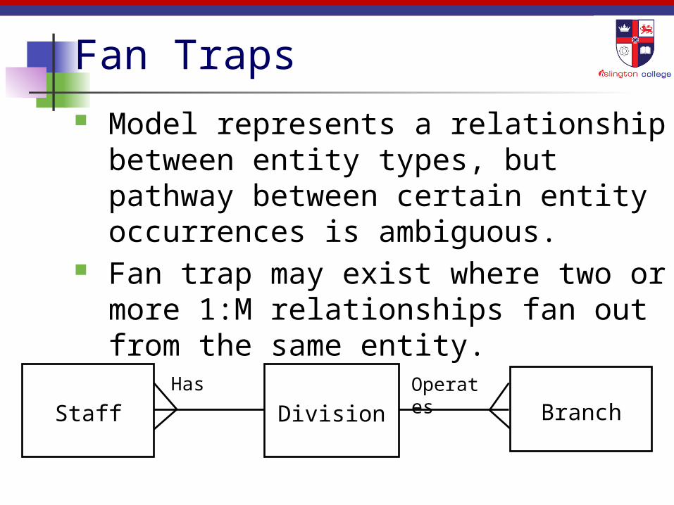
Rule Primary rule of generalization
hierarchies is that each instance of the Supertype entity must appear in at least one Subtype; likewise, an instance of the Subtype must appear in Supertype.
Subtypes can be a part of only one generalization hierarchy. That is, a Subtype cannot be related to more than one Supertype.

Rule Generalization hierarchies may be
nested by having the Subtype of one hierarchy be the Supertype for another.
Subtypes may be parent entity in a relationship but not the child. If this were allowed, the subtype would inherit two primary keys.
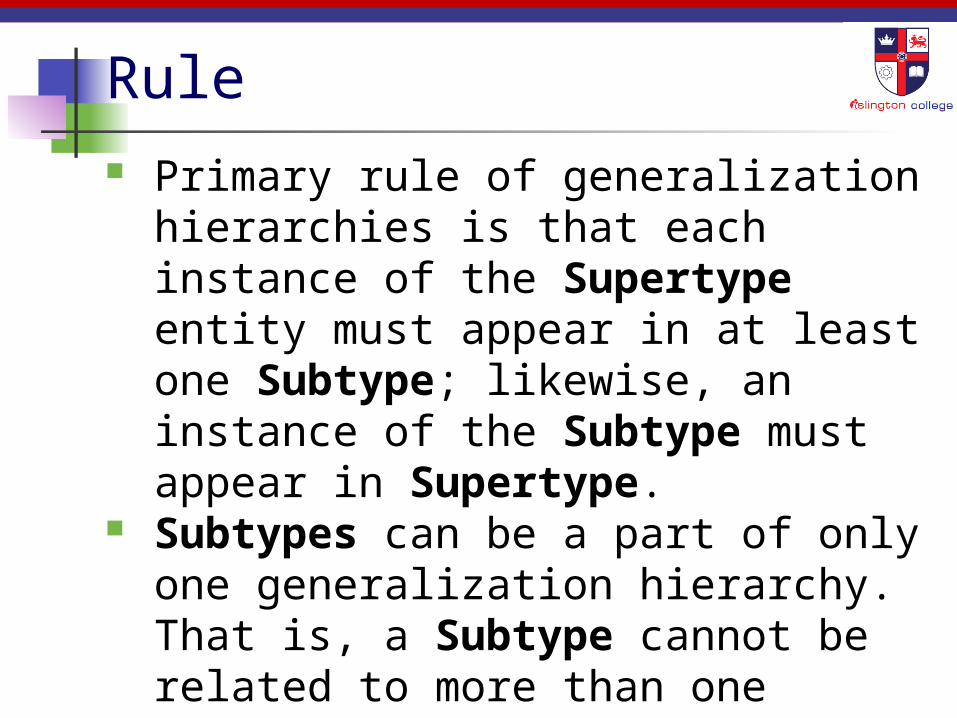
Evaluating ER Model – Example
RESEARCH-REPORT (report-no, title, author) RESEARCH-PROJECT (name, location, grant-number,
date, amount) RESEARCH-TOPIC (name, code, type) RESEARCHER (name, title, phone, office) GRANT-AUTHORITY (name, address, contact)

Evaluation – Possible Queries
Who has written the report entitled “Algorithm Solutions to data modelling”

Evaluation – Possible Queries
Who is involved in the “Functional Database Languages” project ?

Evaluation – Possible Queries
Which topic is addressed by a report for “Intelligent Databases” project ?

Evaluation – Possible Queries
Which researcher is currently working on a particular research topic ?

Evaluation – Possible Queries
Is the year-end report available for Paul Smith ?

Create a Relational Schema
Ward
WardNo
Varchar2(2)
Wname
Varchar2(12)
WType Varchar2(15)
Patient
PatientNo Number(4)
Pname Varchar2(10)
Ptype Varchar2(5)
DOB Date
Balance Number(5)
WardNo Varchar2(2)
Ward (WardNo, WName, WType)
Patient (PatientNo, PName, PType, DOB, Balance, WardNo)

Sample RelationsPatient
PatientNo
PName PType DOB Balance WardNo
100 Rajendra Out 12-MAY-86
1000 W1
101 Rohan Out 30-APR-92 1200 W1
102 Govinda In 07-JUL-80 200 W3
104 Aman In 14-JUN-95 450 W4
105 Birendra Out 25-SEP-92 1200 W2Ward
WardNo WName Wtype
W1 Tej Narayan Outpatient
W2 Til Ganga Optics
W3 ICU Intensive Care
W4 Makalu Renal
Any Questions?