Embed Size (px)
Citation preview

Switch gear and protection
DEP of EEE, MTIET Page 1
UNIT-I
CIRCUIT BREAKERS – I
INTRODUCTION
A switch is used for opening and closing of an electric circuit while a fuse is used for
over-current protection.
Every electrical circuit needs a switching device and protective device.
SWITCHGEAR is a general term covering a wide range of equipment concerned
with switching and protection.
FUNCTIONS OF SWITCHGEAR IN POWER SYSTEMS
Switching during normal operating conditions for the purpose of operation and
maintenance.
Switching during abnormal conditions such as short-circuits and interrupting the fault
currents.
The first of above could be served by relatively simple switches because it is
relatively simple as it involves normal currents which are easy to interrupt.
Due to advancement of electrical power system the lines and other equipment
operates with large voltages and currents.
Whenever a short-circuit occurs, a heavy current flows through the equipment causing
considerable damage to the equipment and interruption of service.
In order to avoid such damage every part of the power system is provided with a
protective relaying system and an associated switching device.
the apparatus including its associated auxiliaries employed for controlling,
regulating or switching on or off the electrical circuits in the electrical power
systems is known as switchgear
ARC PHENOMENA
The arc consists of a column of ionized gas having molecules which have lost one or
more electrons.
The electrons being negatively charged are attracted towards the positive contact with
a high velocity and on the way they detach more electrons by impact.

Switch gear and protection
DEP of EEE, MTIET Page 2
The positive ions are attracted towards the negative contact but as they comprise
almost the entire weight of the atom, they move towards it relatively slowly.
Thus current flow is causes due to movement of electrons.
INITIATION OF AN ARC
For the initiation of an arc it is necessary that the electrons are emitted from the
cathode as soon as the contacts begin to separate on occurrence of fault.
Initiating electrons are thought of produced by the following two processes :
By high voltage gradient at the cathode resulting into field emission
As the moving contact is withdrawn the contact area and the pressure between the
separating contacts decreases and due to decrease in contact area the resistance
increases (it is much less than OHM).
Although contact resistance is quite small but due to large magnitude of fault current a
sufficiently high potential drop, of the order of 106
V/cm, is caused between the
separating contacts so as to dislodge the electrons from the cathode surface.
By increase of temperature resulting into thermionic emission
As the contacts apart, the decrease in the contact area causes increase in current
density to very high value, of the order of 106 A/cm
2.
This very high current density raises the temperature of the contact surface resulting
into thermal emission.
In case of ckt breakers the contacts used are usually of copper, the thermionic
emission from such a metal is quite low and so for initiation of arc, the field emission
is more responsible.
MAINTENANCE OF ARC
The electrons so emitted from the cathode make many collisions with the atoms and
molecules of gases and vapours existing between the two contacts during their
journey towards the anode.
Such collisions cause ionization of atoms and the molecules thus dislodging more
electrons.
The ionization is further facilitated by:
High temperature of the medium around the contacts caused by high current densities,
with high temperature the kinetic energy gained by the moving electrons is increased.

Switch gear and protection
DEP of EEE, MTIET Page 3
The field strength or voltage gradient which increases the kinetic energy of moving
electrons and increases the chances of detaching electrons from neutral molecules.
All the processes (thermal emission, ionization and field emission) may start either
one after the other or almost simultaneously and enable the arc to be initiated and
maintained and finally if the arc current is high, the arc may attain a temperature high
enough for thermal ionization to become the main source of electrical conductivity.
ARC EXTINCTION
When the current carrying contacts of a circuit breaker are opened, an arc is formed,
which persists during the brief period after separation of contacts.
The arc provides a gradual transition from the current carrying state to the voltage
isolating states of the contacts, but it is dangerous on account of the energy generated
in it in the form of heat which may results in explosive force.
The circuit breaker should be capable of extinguishing the arc without causing any
damage to equipment or danger to itself.
The arc plays a vital role in the behavior of the circuit breaker.
The interruption of DC arcs is relatively more difficult than AC arcs.
In AC arcs as the current becomes zero during regular wave, the arc is vanishes and it
is prevented from restriking.
FACTORS RESPONSIBLE FOR MAINTENANCE OF ARC:
Potential difference between the contacts
Ionized particles between the contacts
The potential drop between the aparting contacts is just sufficient to maintain the arc
and is quite small.
One way to extinguish the arc is to separate the contacts to such a distance that the
potential difference becomes inadequate to maintain the arc.
This method is impractical in high voltage systems where a separation of many meters
would be required.
The conductance of arc is proportional to the number of electrons per cubic cm
produced by ionization, the square of the diameter of the arc, and the reciprocal of
length.
The other method for arc extinction is to reduce the density of free electrons, i.e.,
reduce the ionization and decrease the diameter of the arc.

Switch gear and protection
DEP of EEE, MTIET Page 4
The arc extinction can, therefore, be facilitated by deionizing the arc path.
This may be achieved by cooling the arc or by bodily removing ionized particles from
the space between the circuit breaker contacts.
METHODS OF ARC EXTINCTION
There are two methods of arc extinction in circuit breakers
HIGH RESISTANCE METHOD:-
In this method the arc is controlled in such a way that its effective resistance is
increased with the time.
So that the current is reduced to such a value that heat produced by it in not sufficient
to maintain the arc and thus the current is interrupted or arc is extinguished.
The rate at which the resistance is increased or the current is reduced is not abnormal
so as to cause harmful induced voltages in the system.
Due to resistive nature of the arc discharge, most of the energy in the system will be
dissipated with in the circuit breakers.
Therefore, while designing the circuit breaker, provision of mechanical strength to
withstand such sudden release of large quantities of energy must be made.
This is the main drawback of this method of arc extinction and so is restricted to DC
circuit breakers and air break type AC circuit breakers of relatively low capacity of
the order of few hundred MVA
RESISTANCE OF ARC CAN BE INCREASED BY:
COOLING OF ARC:-
Cooling of arc brings about recombination of ionized particles.
This increases the resistance of arc.
Cooling removes the heat from the arc.
Cooling is brought by bringing the arc in contact with cool air.
INCREASING THE LENGTH OF ARC:-
The length of the arc can be increased by increasing the gap between the contacts.
But it is not practicable to draw the arc out to such a length that the voltage available
becomes insufficient to maintain arc.

Switch gear and protection
DEP of EEE, MTIET Page 5
REDUCING THE CROSS-SECTION OF ARC:-
The cross-section of an arc can be reduced by having a small area of contacts or by
letting the arc pass through a narrow opening.
By reducing the area of cross-section of the arc, the voltage necessary to maintain the
arc is increased.
SPLITTING OF ARC:-
The resistance of the arc can be increased by splitting the arc into number of small
arcs in series.
Each one of these arcs experiences the effect of lengthening and cooling.
The arc can be splitted up by introducing some conducting plates between the
contacts.
LOW RESISTANCE OR CURRENT ZERO INTERRUPTION:-
This method is applicable only in AC circuit interruption because there is natural
zero of current 100 times in a second for 50 Hz supply system.
This property of AC circuit is exploited for interruption purposes and the current in
not allowed to rise again after a zero occurs.
It is not desirable to cut off the current at any other point on the AC wave because this
will induce high voltages in the system.
In this method the arc resistance is kept low until the current is zero where the arc
extinguishes naturally and is prevented from restriking after it has gone out at a
current zero.
This method of arc extinction is employed in modern high power AC circuit breakers.
ENERGY BALANCES THEORY:-
This theory states that if the rate of heat dissipation between the contacts is greater
than the rate at which heat is generated, the arc will be extinguished, otherwise it
will restrike.
The heat generated varies from time to time depending upon the separation of breaker
contacts.
When the contacts are about to open, the restriking voltage is zero so heat generated is
zero.

Switch gear and protection
DEP of EEE, MTIET Page 6
When the contacts are fully opened the resistance between contacts is infinite so heat
generated is zero.
Between these two limits the heat generation reaches maximum.
If the heat so generated could be removed by cooling, lengthening and splitting the
arc at a rate higher than that of generation, the arc is extinguished.
RECOVERY RATE THEORY:-
This theory states that if the rate at which the ions and electrons combine to form or
replaced by neutral molecules i.e., the rate at which the gap recovers its dielectric
strength is faster than the rate at which voltage stress rises, the arc will be
extinguished.
Otherwise the arc may be interrupted for a brief period but it again restrikes.
In AC systems current drops to zero after every half cycle.
At every current zero, the arc extinguishes for a brief period.
Now the medium between the breaker contacts contains ions and electrons so that it
has small dielectric strength and can be easily broken down by the rising contact
voltage called the restriking voltage.
If such a breakdown does occur, the arc will persist for another half cycle when the
process will be repeated.
If immediately after the current zero, the dielectric strength of the medium between
breaker contacts is build up more rapidly than the voltage across the contacts, the arc
fails to restrike and current will be interrupted.
The rapid increase of dielectric strength of the medium near current zero can be
achieved by either causing the ionized particles in the space between contacts to
recombine into neutral molecules or sweeping the ionized particles away and
replacing them by un-ionized particles.
The problem is therefore, to remove the ions and electrons either by causing them to
re-combine into neutral molecules or by sweeping them away, as soon as the current
becomes zero, so that the rising contact voltage or restriking voltage cannot
breakdown the space between the contacts.

Switch gear and protection
DEP of EEE, MTIET Page 7
METHODS OF ARC EXTINCTION IN LOW RESISTANCE METHOD:-
LENGTHENING OF THE GAP:-
The dielectric strength or post-zero resistance is proportional to the length of the gap
between the breaker contacts.
So lengthening by rapid opening of the breaker contacts is an obvious process.
The permissible arc length is limited, however by other considerations.
INCREASING THE PRESSURE IN THE VICINITY OF THE ARC:-
By increasing the pressure the density of particles constituting the discharge also
increases.
The increased density of particles causes higher rate of deionization and thus the
dielectric strength of the medium between the contacts is increased.
COOLING:-
If the particles are allowed to cool the natural combination of ionized particles will
take place more rapidly resulting in dielectric strength of the medium.
Cooling by conduction to adjacent parts.
IMPORTANT TERMS USED IN THE CIRCUIT BREAKER ANALYSIS:-
ARC VOLTAGE:-
It is the voltage that appears across the contacts of the circuit breaker during the
arcing period.
As soon as the contacts of the circuit breaker separate, an arc is formed.
The voltage that appears across the contacts during arcing period is called the arc
voltage.
Its value is low except for the period the fault current is at or near zero current point.
At current zero, the arc voltage rises rapidly to peak value and this peak voltage tends
to maintain the current flow in the form of arc.

Switch gear and protection
DEP of EEE, MTIET Page 8
RESTRIKING VOLTAGE:-
It is the transient voltage that appears across the contacts at or near current zero
during arcing period.
At current zero, a high-frequency transient voltage appears across the contacts and is
caused by the rapid distribution of energy between the magnetic and electric fields
associated with the plant and transmission lines of the system.
This transient voltage is known as restriking voltage.
The current interruption in the circuit depends upon this voltage.
If the restriking voltage rises more rapidly than the dielectric strength of the medium
between the contacts, the arc will persist for another half-cycle.
If the dielectric strength of the medium builds up more rapidly than the restriking
voltage, the arc fails to restrike and the current will be interrupted.
RECOVERY VOLTAGE:-
It is the normal frequency (50 Hz) r.m.s voltage that appears across the contacts of
the circuit breaker after final arc extinction.
It is approximately equal to the system voltage.
When contacts of the circuit breaker are opened, current drops to zero after every half
cycle.
At some current zero, the contacts are separated sufficiently apart and dielectric
strength of the medium between the contacts attains a high value due to removal of
ionized particles.
At such instant, the medium between the contacts is strong enough to prevent the
breakdown by the restriking voltage.

Switch gear and protection
DEP of EEE, MTIET Page 9
Consequently, the final arc extinction take place and circuit current is interrupted.
Immediately after final current interruption, the voltage that appears across the
contacts has a transient part.
However these transient oscillations die rapidly due to the damping effect of system
resistance and normal circuit voltage appears across the contacts.
The voltage across the contacts is of normal frequency and is known as recovery
voltage.
PROBLEMS OF CIRCUIT INTERRUPTION:-
A power system contains an appreciable amount of inductance and some capacitance.
When fault occurs, the energy Stored in the system can be considerable.
Interruption of fault current by a circuit breaker will results in most of the stored
energy dissipated within the circuit breaker, the remainder being dissipated during
oscillatory surges in the system.
This surges are undesirable and, therefore the circuit breaker must be designed to
dissipate as much of the stored energy as possible.
The above figures shows a short-circuit occurring on the transmission line. And its
equivalent circuit where L is the inductance per phase up to the point of fault and C is
the capacitance per phase of the system.
The resistance of the system is neglected as it is generally small.
CURRENT CHOPPING:-
It is the phenomenon of current interruption before the natural current zero is
reached.
Current chopping is mainly occurs in air-blast circuit breakers because they retain the
same extinguishing power irrespective of magnitude of the current to be interrupted.
Switch gear and protection
DEP of EEE, MTIET Page 10
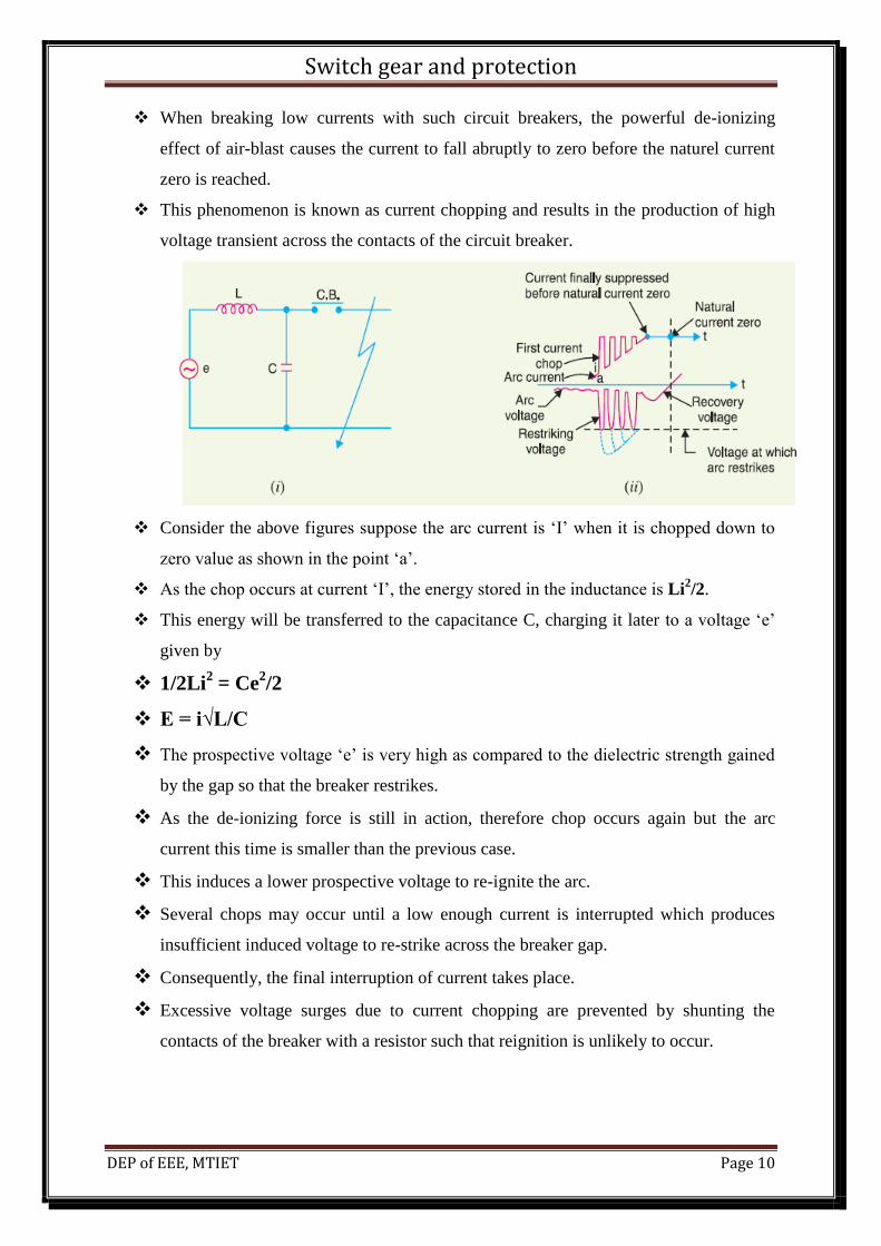
When breaking low currents with such circuit breakers, the powerful de-ionizing
effect of air-blast causes the current to fall abruptly to zero before the naturel current
zero is reached.
This phenomenon is known as current chopping and results in the production of high
voltage transient across the contacts of the circuit breaker.
Consider the above figures suppose the arc current is ‘I’ when it is chopped down to
zero value as shown in the point ‘a’.
As the chop occurs at current ‘I’, the energy stored in the inductance is Li2/2.
This energy will be transferred to the capacitance C, charging it later to a voltage ‘e’
given by
1/2Li2 = Ce
2/2
E = i√L/C
The prospective voltage ‘e’ is very high as compared to the dielectric strength gained
by the gap so that the breaker restrikes.
As the de-ionizing force is still in action, therefore chop occurs again but the arc
current this time is smaller than the previous case.
This induces a lower prospective voltage to re-ignite the arc.
Several chops may occur until a low enough current is interrupted which produces
insufficient induced voltage to re-strike across the breaker gap.
Consequently, the final interruption of current takes place.
Excessive voltage surges due to current chopping are prevented by shunting the
contacts of the breaker with a resistor such that reignition is unlikely to occur.

Switch gear and protection
DEP of EEE, MTIET Page 11
RESISTANCE SWITCHING:-
Current chopping gives rise to severe voltage oscillations.
These excessive voltage surges during circuit interruption can be prevented by the use
of shunt resistance R connected across the circuit breaker contacts as shown in the
equivalent circuit. This is known as resistance switching.
When a fault occurs, the contacts of the circuit breaker are opened and an arc is struck
between the contacts.
Since the contacts are shunted by resistance R, a part of arc current flows through this
resistance.
This results in the decrease of arc current and an increase in the rate of de-ionization
of the arc path.
Consequently the arc resistance is increased.
The increased arc resistance leads to a further increase in current through shunt
resistance.
This process continues until the arc current becomes so small that it fails to maintain
the arc.
Now, the arc is extinguished and circuit current is interrupted.
The shunt resistor also helps in limiting the oscillatory growth of re-striking voltage.
The natural frequency of oscillations of the circuit shown in figure is given by

Switch gear and protection
DEP of EEE, MTIET Page 12
The effect of shunt resistance R is to prevent the oscillatory growth of re-striking
voltage and cause it to grow exponentially up to recovery voltage.
This is effective when the value of R is chosen that the circuit is critically damped.
The value of R required for critical damping is 0.5√L/C.
The above figure shows the oscillatory growth and exponential growth when the
circuit is critically damped.
RATINGS OF CIRCUIT BREAKERS
A circuit breaker should operate under all conditions.
Under fault conditions, a circuit breaker is required to perform the following duties:-
It must be capable of opening the faulty circuit and breaking the fault current.
It must be capable of being closed on to a fault.
It must be capable of carrying fault current for a short time while another circuit
breaker is clearing the fault.
Depending up on the above duties the circuit breakers have three ratings
BREAKING CAPACITY:-
It is current (r.m.s) that a circuit breaker is capable of breaking at given recovery
voltage and under specified conditions.
The breaking capacity is always stated at the r.m.s value of fault current at the instant
of contact separation.
When a fault occurs, there is considerable asymmetry in the fault current due to the
presence of a DC component.
The DC component dies rapidly, with a decrement factor being 0.8 per cycle.

Switch gear and protection
DEP of EEE, MTIET Page 13
Consider the above figure, let the contacts are separated at DD1.
At this instant, the fault current has
X=maximum value of AC component
Y=maximum value of DC component
Therefore symmetrical breaking current = r.m.s value of AC component
Asymmetrical breaking current = r.m.s value of total current
It is common practice to express the breaking capacity in MVA by taking into account
the rated breaking current and rated service voltage.
Thus, if I is the rated breaking current in amp and V in the rated service line voltage
in volts, then for a 3-phase circuit
Breaking capacity = √3 x V x I x 10-6
MVA.
MAKING CAPACITY:-
There is always a possibility of closing or making the circuit under short-circuit
conditions.
The capacity of a breaker to make current depends upon its ability to withstand and
close successfully against the effects of electromagnetic forces.
These forces are proportional to the square of maximum instantaneous current on
closing.
Therefore making capacity is stated in terms of a peak value of current instead of
r.m.s value.
Switch gear and protection
DEP of EEE, MTIET Page 14
The peak value of current (including DC component) during the first cycle of current
wave after the closure of circuit breaker is known as making capacity.
It may be noted that the definition is concerned with the first cycle of current wave on
closing the circuit breaker.
This is because the maximum value of fault current possibly occurs in the first cycle
only when maximum asymmetry occurs in any phase of the breaker.
In other words, the making current is equal to the maximum value of asymmetrical
current.
To find this value, we must multiply symmetrical breaking current by √2 to convert
this from r.m.s to peak, and then by 1.8 to include the ‘doubling effect’ of maximum
asymmetry.
The total multiplication factor becomes √2 x 1.8 = 2.55.
Making capacity = 2.55 x symmetrical breaking capacity.
SHORT-TIME RATING:-
It is the period for which the circuit breaker is able to carry fault current while
remaining closed.
Sometimes a fault on the system is of temporary nature and persists for 1 or 2 seconds
after which the fault is automatically cleared.
In the interest of continuous supply, the breaker should not trip in such situations.
This means the circuit breaker should carry high safely for some specific time period
while remaining closed.
If the fault persists for duration longer than the specified time limit, the circuit breaker
will trip and disconnect the faulty section.
The short time of the circuit breaker depends upon its ability to withstand the
electromagnetic forces and temperature rise.
NORMAL CURRENT RATING:-
It is the r.m.s value of current which the circuit breaker is capable of carrying
continuously at its rated frequency under specified conditions.
Switch gear and protection
DEP of EEE, MTIET Page 15
IMPORTANT QUESTIONS
Discuss the arc phenomenon in the circuit breakers?
Explain various methods of arc extinction in circuit breakers?
Define and explain the following terms applied to circuit breakers?
Arc voltage
restriking voltage
recovery voltage
Write a short note on RRRV and derive its equation and importance in arc extinction?
Discuss the phenomenon of current chopping?
Write a short note on resistance switching?
What are the ratings of circuit breakers explain about them?