Embed Size (px)
Citation preview
Santa Clara UniversityScholar Commons
Mechanical Engineering Senior Theses Engineering Senior Theses
6-12-2014
Swing wing aerial drone (SWAD)Chris BartonSanta Clara University
Robert GomezSanta Clara University
Matt KochalkoSanta Clara University
Kyle NakagakiSanta Clara University
Follow this and additional works at: https://scholarcommons.scu.edu/mech_senior
Part of the Mechanical Engineering Commons
This Thesis is brought to you for free and open access by the Engineering Senior Theses at Scholar Commons. It has been accepted for inclusion inMechanical Engineering Senior Theses by an authorized administrator of Scholar Commons. For more information, please contact [email protected].
Recommended CitationBarton, Chris; Gomez, Robert; Kochalko, Matt; and Nakagaki, Kyle, "Swing wing aerial drone (SWAD)" (2014). MechanicalEngineering Senior Theses. 26.https://scholarcommons.scu.edu/mech_senior/26
ii
DEPARTMENT
CHAIR
SWING WING AERIAL DRONE (SWAD)
by
Chris Barton, Robert Gomez, Matt Kochalko, Kyle Nakagaki
SENIOR DESIGN PROJECT REPORT
Submitted in partial fulfillment of the requirements
for the degree of
Bachelor of Science in Mechanical Engineering
School of Engineering
Santa Clara University
Santa Clara, California
June 12, 2014
iii
Abstract
Drones are unmanned aerial vehicles that have a variety of different applications in the
field. Drones are very helpful for first responders such as firefighters, police, and even ranchers
and large landowners. Most drones have a fixed wing. This report will show the design,
construction, and fluid dynamic testing of a drone that has multiple wing positions. These
modes are the straight wing position and swept back position. This design will change the flight
profile of the plane, allowing for the user to launch at a faster speed and the glider to get to the
desired location faster. Once the glider is at the desired location the wings can sweep forward to
the straight position for more control. More control allows for better surveillance of an area.
The wind tunnel was used to test drag and lift on models of our glider. Tests were done on three
models: one straight wing model, one model with wings swept back 17.5°, and one model with
wings swept back 25°. These models were also tested at multiple angles of attack between ‐15°
to 15° in 5° increments. It was determined that, as the wings swept back, the models produced
more drag. The straight wing model produced 0.393 lbs. of drag, the 17.5° model produced 1.09
lbs. of drag, and the 25° model produced 0.7 lbs. of drag. There were insufficient tests for lift
that produced correct data. After these wind tunnel tests, a mechanism was implemented on
the commercially available glider, the Radian Pro, that sweeps the wing back 25°. Once this was
implemented, a flight test was conducted to compare models
iv
Acknowledgements
We would like to acknowledge the dedication and assistance provided by our two thesis
advisors, Dr. Djordjvic and Dr. Fabris. Without them the project would not have been as
successful as it was. We would also like to thank Don Maccubbin for his assistance in the
machining process and mechanical engineering labs, as well as Professor Hight for all the
help in the combination of the senior design process. Finally we would like to thank the
Santa Clara University School of Engineering for the generous funding and support
throughout the entirety of this project.
1
TableofContentsAbstract ........................................................................................................................................... iii
Chapter 1: Introduction ................................................................................................................... 1
Chapter 2: Overall System Integration ............................................................................................ 2
Section A: System‐level overview ................................................................................................ 2
Section B: Customer Needs and System Level Requirements ..................................................... 3
Section C: Sketch of Flight ............................................................................................................ 4
Section D: Benchmarking Results ................................................................................................ 4
Section E: Layout of System Level Design with main subsystems ............................................... 5
Section F: Team and Project Management .................................................................................. 5
Chapter 3: Subsystem‐Wing Modification ....................................................................................... 6
Section A: Introduction ................................................................................................................ 6
Section B: Trade off Analysis ........................................................................................................ 6
Chapter 4: Subsystem ...................................................................................................................... 8
Section A: Mechanism Design ...................................................................................................... 8
Chapter 5: Subsystem‐Data Acquisition ........................................................................................ 15
Section A: Full Size Benchmark Testing...................................................................................... 15
Section B: Wind tunnel Testing ................................................................................................. 18
Chapter 6: System integration, Test and Results ........................................................................... 22
Chapter 7: Cost Analysis ................................................................................................................ 26
Chapter 8: Business Plan ................................................................................................................ 28
Chapter 9: Engineering Standards and Realistic Constraints ......................................................... 29
Section A: Ethical Impact ........................................................................................................... 29
Section B: Environmental Impact ............................................................................................... 30
Section C: Manufacturability ..................................................................................................... 31
Section D: Social Impact ............................................................................................................. 32
Section E: Economic Impact ....................................................................................................... 33
Chapter 10: Summary and Conclusion ........................................................................................... 33
Appendix A: Additional Information .............................................................................................. 36
Appendix B: Machine Drawings ..................................................................................................... 37
2
Appendix C: Drawings .................................................................................................................... 49
Appendix D: Equations ................................................................................................................... 51
Appendix E: Senior Design Conference Slideshow Presentation ................................................... 53
Appendix F: Time Line and Gantt Charts ....................................................................................... 59
1
TableofFiguresFigure 1: Image of overall system with dotted line indicating different sub systems (Drawing by
Chris Barton) .................................................................................................................................... 2
Figure 2: Shows a sketch of the intended flight of our designed drone. (Drawing by Matt
Kochalko) ......................................................................................................................................... 4
Figure 3: Layout of system with main subsystems (Drawing by Matt Kochalko) ............................ 5
Figure 4: Picture of how center of gravity and center of lift affect the plane (image is public
domain) ............................................................................................................................................ 7
Figure 5: Sketch of wing modification idea sliding the base of the wings forward on the body
(Drawing by Kyle Nakagaki) ............................................................................................................. 7
Figure 6: Sketch of mesh attached to wings and body (Drawing by Kyle Nakagaki) ....................... 8
Figure 7: Four Bar Mechanism (Image by Robert Gomez) ............................................................. 12
Figure 8: Analytical approach to designing the mechanism (Image by Robert Gomez) ................ 13
Figure 9: Wiring diagram (Image by Robert Gomez) ..................................................................... 14
Figure 10: Swinging wing mechanism of flown model .................................................................. 15
Figure 11: Flight route for the control test (Image by Chris Barton) ............................................. 16
Figure 12: Flight route for the maneuverability test (Image by Chris Barton) .............................. 17
Figure 13: SolidWorks models of the Radian Pro glider ................................................................ 18
Figure 14: 3D printed models used for wing tunnel testing .......................................................... 19
Figure 15: Load cell design with variable angle of attack .............................................................. 20
Figure 16: Testing of 12.5 degree wing sweep .............................................................................. 21
Figure 17: Sting Design Issues (Image by Chris Barton) ................................................................. 21
Figure 18: Non‐elastic wire used to secure sting ........................................................................... 22
Figure 19: Drag Coefficient vs. Angle of Attack for 3 models ........................................................ 23
Figure 20: Newest airplane model in straight wing position ......................................................... 25
Figure 21: Newest airplane model in swept position .................................................................... 25
Figure 22: Detail drawing with BOM of plane................................................................................ 38
Figure 23: Detail drawing of body of plane.................................................................................... 39
Figure 24: Detail drawing of nose cone ......................................................................................... 40
Figure 25: Detail drawing of back wing .......................................................................................... 41
Figure 26: Detail drawing of tail ..................................................................................................... 42
Figure 27: Detail drawing of wings ................................................................................................ 43
Figure 28: Support post ................................................................................................................. 44
Figure 29: Top support ................................................................................................................... 45
Figure 30: Side Support .................................................................................................................. 46
Figure 31: Center Support .............................................................................................................. 47
Figure 32: Center Support 2 ........................................................................................................... 48
Figure 33: Possible wing extension design .................................................................................... 49
Figure 34: Basic functions expected from the drones actions ....................................................... 50
Figure 35: General Lift and Drag Equations ................................................................................... 51
2
Figure 36: Equations to determine model sizes ............................................................................ 52
Figure 37: PowerPoint slides 1 ....................................................................................................... 53
Figure 38: PowerPoint Slides 2 ...................................................................................................... 54
Figure 39: PowerPoint Slides 3 ...................................................................................................... 55
Figure 40: PowerPoint Slides 4 ...................................................................................................... 56
Figure 41: PowerPoint Slides 5 ...................................................................................................... 57
Figure 42: PowerPoint Slides 6 ...................................................................................................... 58
Figure 43: Timeline 1 ...................................................................................................................... 59
Figure 44: Timeline 2 ...................................................................................................................... 60
Figure 45: Timeline 3 ...................................................................................................................... 61
1
Chapter1:Introduction
An unmanned aerial vehicle (UAV), or drone, is an airplane that does not have a pilot on
board and can perform a task a distance away from its controller. A drone is controlled on the
ground by remote control, or by onboard computers in larger drones. Drones are commonly
thought of as military vehicles sent out for reconnaissance or precision strikes, but those are but
a fraction of the unmanned vehicle uses today. Civilian drone uses range from landscaping,
photography, action video, movie production, environmental work, crop monitoring, livestock
locating, and poaching prevention, just to name a few. The rise of unmanned vehicles in the past
decade has been so abrupt that there is tremendous pressure on the FAA to come up with
regulations dictating when and where drones can be flown by civilians. It is estimated that by
2020 there will be over 30,000 drones flying around U.S. airspace1. The large variety of uses, and
increase in demand for drones, enables the expansion of drone usage to any arena that could
benefit from cheap, reliable services of transport and action. There are many different types of
drones on the market that mostly fall into six different categories. These categories include
target and decoy, reconnaissance, combat, logistics, research and development, and
commercial.
The Swing Wing Aerial Drone (SWAD) team has built a drone with a dynamic wing
design. This drone can be easily launched and controlled by one person. We have tested the
wing properties at different sweep angles to determine if the creation of a two position wing is
desirable for a small sized airplane. The main goal of our project was to conduct research on
wing shape and design to assist in the creation of a new type of small plane that will have
advantages compared to other models sold in the current market.
The project has followed a very straightforward and organized plan. The first step was to
purchase a model airplane and test its performance. The purpose of this was to find base values
of the design to compare our final plane design against. Secondly, we designed and built a
variety of plane models with different wing sweeps that were tested in the Santa Clara
University wind tunnel. Similarly, 3D models of wing shapes and drone bodies were designed
1 "From the Burrito Bomber to Crop Monitoring, a Look at Commercial Drone Use." The Drone Project. N.p., n.d. Web. 08 June 2014.
2
using SolidWorks. These tests showed us the advantages of each wing sweep and design and
helped us choose the most effective and reliable shape of our full sized model. The modification
of the purchased drone consisted of designing the mechanism and strength testing the model
airplane. The final result of this project was a modified model airplane with sweeping wings that
was tested to show the advantages of our new design against the original base values.
Chapter2:OverallSystemIntegration
SectionA:System‐leveloverview
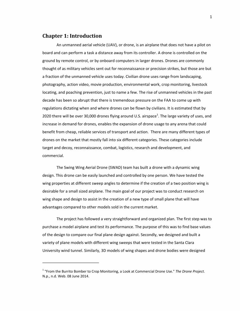
The drone has two main systems: the dynamic wing shape and the mechanism used to
move and hold the wing during flight. These two systems are complemented by the baseline
data found from the initial plane we purchased and tested. This data allows for verification of
advancement when projected against the new drone’s data for the same experiment. Finally, a
requirement was made for our drone to take off and land without any additional assistance.
Figure 1: Image of overall system with dotted line indicating different sub systems (Drawing by Chris Barton)
3
SectionB:CustomerNeedsandSystemLevelRequirements
To get a better understanding of our customer needs we interviewed both a border
patrol worker who works on the military full size predator drone, and an RC enthusiast who has
been flying custom hobby planes for over two years. Based on interviews with these
professionals, and other Santa Clara University Mechanical Engineering students, our team has
designed improvements catered to our customer needs. The key customer types for use of a
similar drone consist of: military, police, border patrol, fire department, large landowners,
ranchers and RC enthusiasts. It is important for the drone to be efficient in energy use during
flight and have a flight time of over one hour. It is our intention to improve efficiency by
decreasing the drag coefficient on the wings in the swept position.
Increasing the available payload weight will allow the plane to carry a larger battery
which will improve the flight time of the drone. Also an increased payload will allow for the
drone to have GPS systems and video surveillance on board to serve various purposes. To
improve upon the maintenance of the drone, the wing mechanism needs to be easily removed
and taken apart in order to be repaired or replaced.
In order for the drone to fly in potentially dangerous environments (fires, high winds,
and storms), the body and components must be weather resistant. The wing was constructed of
a durable and lightweight material that must have an operating temperature range between 0‐
110 degrees Celsius. It also must be able to perform with wind speeds up to 15 mph.
Using a dynamic wing will allow the drone to have an increased altitude of flight which
will also improve the stealth of the drone. We plan to design the drone to be able to fly high
enough so people on the ground will not be able to hear it, which will also increase the stealth
of the drone. Maneuverability is always needed for proper surveillance, especially since at the
speeds we are flying the drone will only need to be able to maneuver in a figure eight path or a
big circle. Little maneuverability will be needed for the flight of this drone.
4
SectionC:SketchofFlight
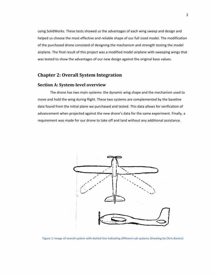
Seen below is a sketch of the intended flight pattern of our designed drone. From launch
to landing, the aircraft will use both wing positions to take advantage of the both aerodynamic
properties. However simple the sketch, it shows the basic concept intended for the craft to
serve a task via remote control and return to the same launching point safely. The wings will
sweep in flight as many times as desired, allowing for the most control and maneuverability
desired in each situation of the flight.
Figure 2: Shows a sketch of the intended flight of our designed drone. (Drawing by Matt Kochalko)
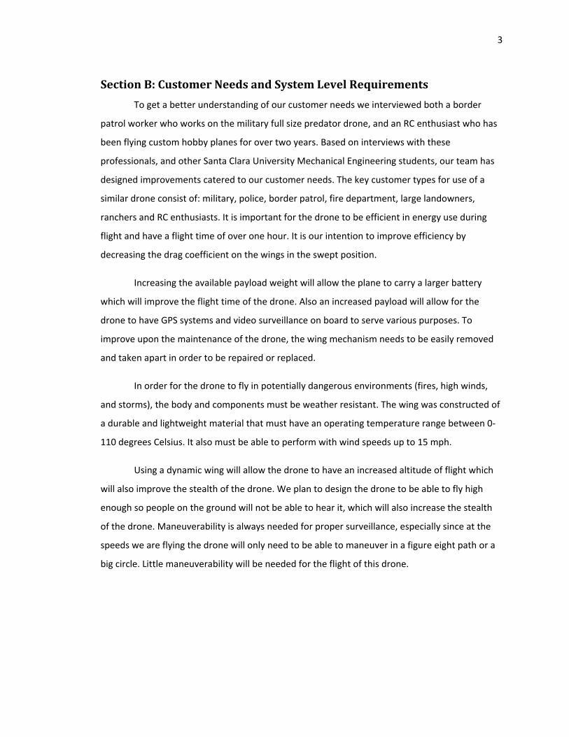
SectionD:BenchmarkingResults
Below is a table of two competitor drones that are used in similar operations.
Table 1: Similar Existing Drone Model Specifications
Model Wingspan Flight Time
Launch Range Speed Weight
Killer Bee 6.5 ft. 10-24 hrs. Mobile Launcher
100 miles 68 mph 8 lbs.
Zepher 4.5 ft. 1 hr. Hand Thrown
60 mph 4 lbs.
5
SectionE:LayoutofSystemLevelDesignwithmainsubsystems
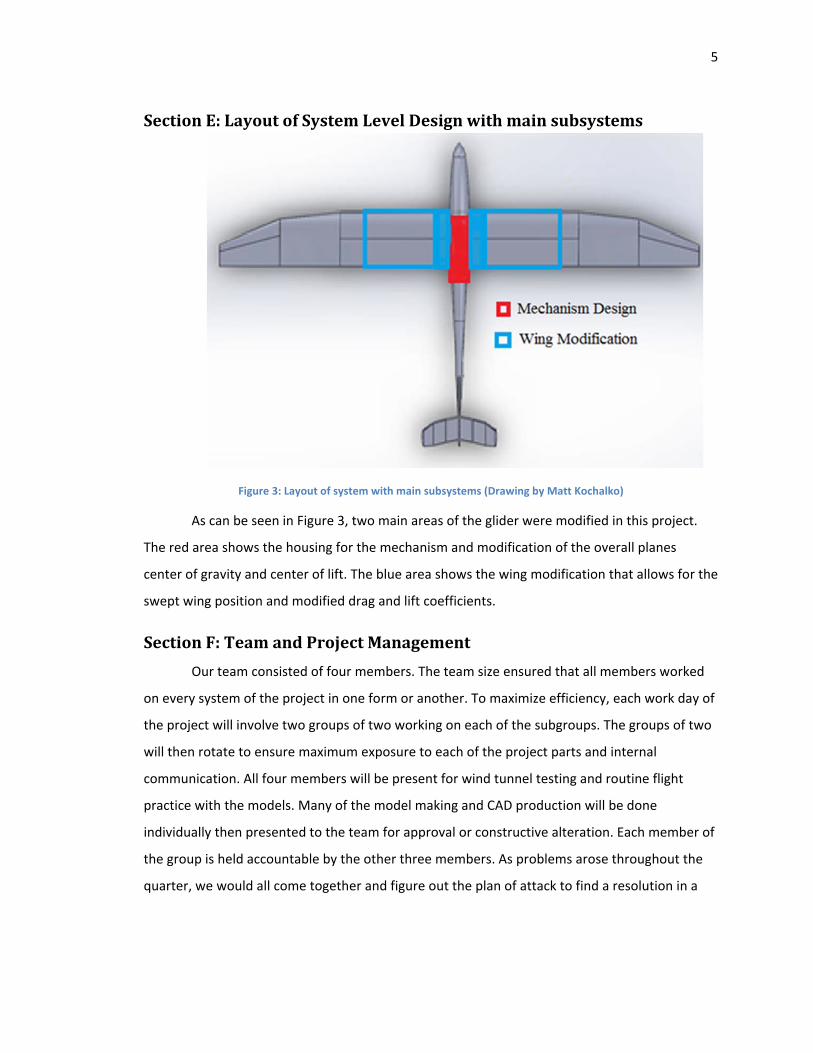
Figure 3: Layout of system with main subsystems (Drawing by Matt Kochalko)
As can be seen in Figure 3, two main areas of the glider were modified in this project.
The red area shows the housing for the mechanism and modification of the overall planes
center of gravity and center of lift. The blue area shows the wing modification that allows for the
swept wing position and modified drag and lift coefficients.
SectionF:TeamandProjectManagement
Our team consisted of four members. The team size ensured that all members worked
on every system of the project in one form or another. To maximize efficiency, each work day of
the project will involve two groups of two working on each of the subgroups. The groups of two
will then rotate to ensure maximum exposure to each of the project parts and internal
communication. All four members will be present for wind tunnel testing and routine flight
practice with the models. Many of the model making and CAD production will be done
individually then presented to the team for approval or constructive alteration. Each member of
the group is held accountable by the other three members. As problems arose throughout the
quarter, we would all come together and figure out the plan of attack to find a resolution in a
6
timely manner. Our team is continuing to improve our team bonding and will continue to be a
tight knit group that works together to overcome each and every challenge.
Chapter3:Subsystem‐WingModification
SectionA:Introduction
To create a successful new model of the glider, modifications need to be done to the
wings. The flight profile will change when we sweep the wings back. There were a few different
tradeoffs we came up with for new designs for the wings. In the following pages, we will discuss
the tradeoffs of a new design when sweeping the wings back.
SectionB:TradeoffAnalysis
There were a couple of different possibilities for the wing modification. One of the
major consequences of sweeping the wings back is the change in the center of gravity. The
center of gravity moves back closer to the center of pressure of the wings. It was imperative we
keep the center of gravity in front of the center of pressure (center of lift) so the plane will be
able to fly. If the center of gravity is too close to the center of lift, the plane will be unstable and
can be put into a nose dive. If the center of gravity is too far in front of the center of lift the
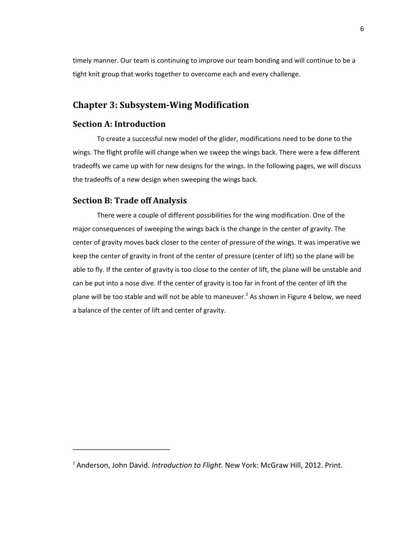
plane will be too stable and will not be able to maneuver.2 As shown in Figure 4 below, we need
a balance of the center of lift and center of gravity.
2 Anderson, John David. Introduction to Flight. New York: McGraw Hill, 2012. Print.
7
Figure 4: Picture of how center of gravity and center of lift affect the plane (image is public domain)
When the wings sweep back, the center of gravity will move back to cancel out the
effects on the plane when this occurs the plane will need to generate more lift.
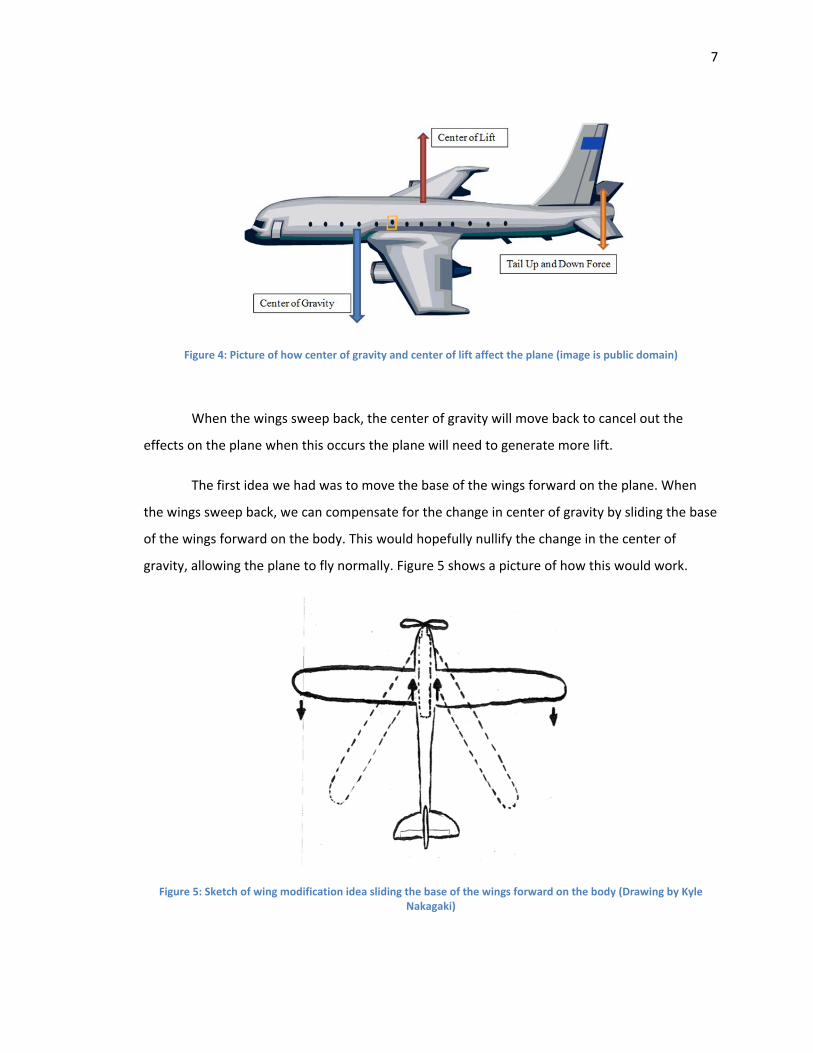
The first idea we had was to move the base of the wings forward on the plane. When
the wings sweep back, we can compensate for the change in center of gravity by sliding the base
of the wings forward on the body. This would hopefully nullify the change in the center of
gravity, allowing the plane to fly normally. Figure 5 shows a picture of how this would work.
Figure 5: Sketch of wing modification idea sliding the base of the wings forward on the body (Drawing by Kyle Nakagaki)
8
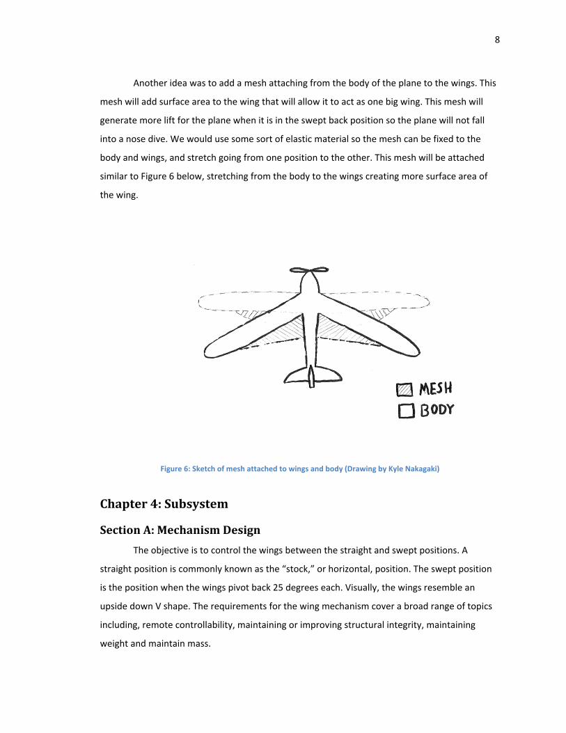
Another idea was to add a mesh attaching from the body of the plane to the wings. This
mesh will add surface area to the wing that will allow it to act as one big wing. This mesh will
generate more lift for the plane when it is in the swept back position so the plane will not fall
into a nose dive. We would use some sort of elastic material so the mesh can be fixed to the
body and wings, and stretch going from one position to the other. This mesh will be attached
similar to Figure 6 below, stretching from the body to the wings creating more surface area of
the wing.
Figure 6: Sketch of mesh attached to wings and body (Drawing by Kyle Nakagaki)
Chapter4:Subsystem
SectionA:MechanismDesign
The objective is to control the wings between the straight and swept positions. A
straight position is commonly known as the “stock,” or horizontal, position. The swept position
is the position when the wings pivot back 25 degrees each. Visually, the wings resemble an
upside down V shape. The requirements for the wing mechanism cover a broad range of topics
including, remote controllability, maintaining or improving structural integrity, maintaining
weight and maintain mass.
9
The mechanism needs to be controlled wirelessly by remote control. Having wires
connecting to an already remote control plane is dangerous and decreases maneuverability. The
plane is capable of a ¼ mile flying radius and speeds of up to 25 mph. At these conditions, the
plane would require a lot of wire, and it would increase the overall weight of the plane and
increase drag. This would result in the plane dragging or whipping the wires through the air,
potentially catching power lines and other obstacles that might pose a hazard.
The mechanism needs to be able to move from one position (swept or straight) to the
other in a fraction of a second. The wings should change positions quickly so the user can react
to the change in flying dynamics. For example, if the wings take 10 seconds to change positions,
it will have varying flying characteristics for 10 seconds, which means unstable flight for
however long the wings are changing and could result in a lost plane.
The plane needs to maintain its structural integrity. The plane is made from injection
molded foam that works well for the stock plane due to the added stresses on the plane from
two concentrated wing support pivots and the removal of foam for the added mechanism. The
plane’s mid‐section is now weaker because it is experiencing much larger forces than before,
and the removal of foam decreases the planes stiffness. The structural integrity is reinforced
with carbon fiber rods and epoxy to replace the lost stiffness.
The mechanism will need to be strategically placed in the fuselage of the plane in order
to maintain the center of mass in front of the center of pressure. If the center of mass is moved
behind the center of pressure, the plane will become uncontrollable. The center of pressure in
most commercial planes does not move. With the swing wing design, the center of pressure
changes depending on the location of the wings. The center of mass also changes with the
swept wing. Carefully understanding and analyzing how the mass changes with the change in
the center of pressure will help manage this problem.
First, we found it an easy tradeoff to go wireless instead of the standard wired
approach. The decision to go with the wireless setup started with ease of integration. The
purchased plane already is remote controlled with the capability of additional servos. The
downside of the wireless is small but still worth mentioning. The batteries on the plane drain
more quickly due to the additional energy needed for the servos to control the wings. Our
10
project is not concerned with this small change in battery life. If we wanted to increase the
battery life, we could purchase an upgraded battery. The wired system had a lot of downsides.
The wires would create extra weight and drag. Also, the wires can easily get wrapped around
poles and other dangerous obstructions like power lines. The bonus of having the servos
hardwired to the operator would be to minimize already small traces of radio interference and
chatter. The decision was made to go wireless for its ease of use.
Early in the project, we were stuck on the question of how to move the wings. We had
the choice of a rotational servo commonly found on RC model planes, or a screw type actuator
commonly found on precision machinery. The rotational servo works by rotating a control arm a
desired (programmed) amount. The chord length, from the starting position of the arm to the
desired position, is the amount of “throw” or motion out of the servo. If the servo rotates the
arm 180 degrees, then the throw will be 2 ∗ radiusor length of the arm. If the servo rotates the
arm 90 degrees, then the throw will be√2 ∗ radius. The screw type actuator pushes and pulls
depending on how you rotate the screw, and how many rotations. An example is how your
deodorant container works. When you twist the bottom of the deodorant stick 1 revolution, the
deodorant generally pushes out an 1/8th of an inch. A screw type actuator has more torque
more static friction which is good for keeping the wings fixed in the desired position without
using extra battery. The downside is that they are often heavy (metal parts), about 10 times
slower, expensive, and require more programing in the controller. The positives for a rotational
servo are the plug‐n‐play ability, available replacement parts, fast movement, and
programmability. The downside is that the rotational servos are weak and break often. Many
were broken while testing.
The final compromise was in designing the wing mechanism. A four bar mechanism is
the simplest movable closed chain linkage. It consists of four bodies, called bars or links,
connected in a loop by four joints. Generally, the joints are configured so the links move in
parallel planes, and the assembly is called a planar four‐bar linkage. The wing mechanism was
originally designed for the wing itself to act as the coupler, because that link has the special
ability to rotate and move position in combination. Unfortunately this setup would create more
forces on weaker parts, and would therefore limit the overall structural integrity of the plane.
11
The wing was then moved forward to the rocker position, which simplified the problem by
reducing the amount of support required on the wing.
Our main design challenge was to get 25 degrees of travel out of a small and lightweight
mechanism that fit within the fuselage of the plane and most importantly maintained the center
of mass in front of the center of lift for both positions. To design the mechanism we started with
constraints to limit our design to a specific volume within the fuselage. The fuselage is oval
shape in cross section but we are simplifying the geometry to a rectangular cross section of 2” x
3”. We were limited forward of the wing due to other RC components in the way. Thus the
forwardest the mechanism could been added was to the front of the leading edge of the wing.
To test how far back the servos can be located without moving the center of mass behind the
center of lift we conducted a mass balance test (summing the moments) knowing all the
components mass and the distance to the center of lift. This test concluded the 2 servos can
positioned up to 16 inches behind the leading edge of the wing. This gave us confidence that we
had plenty of room to move the 2 servos behind the wings. After the analysis we were left with
a volume of 16” x 2” x 3” starting back from the leading edge of the wing to design our
mechanism within.
Now with the space constraints in place the actual lengths of the members could be
determined. The mechanism has a total number of 4 members, comprised of the crank, linkage,
wing, and body. The body acts as the fixed link. It does not move in reference to the other links.
The wing pivots off the front of the body. The wing also has the linkage connected to it at the
trailing end of the wing. The other end of the linkage is connected the crank. And the crank is
connected to the servo which is fixed to the body. The following can be seen in the figure below.
12
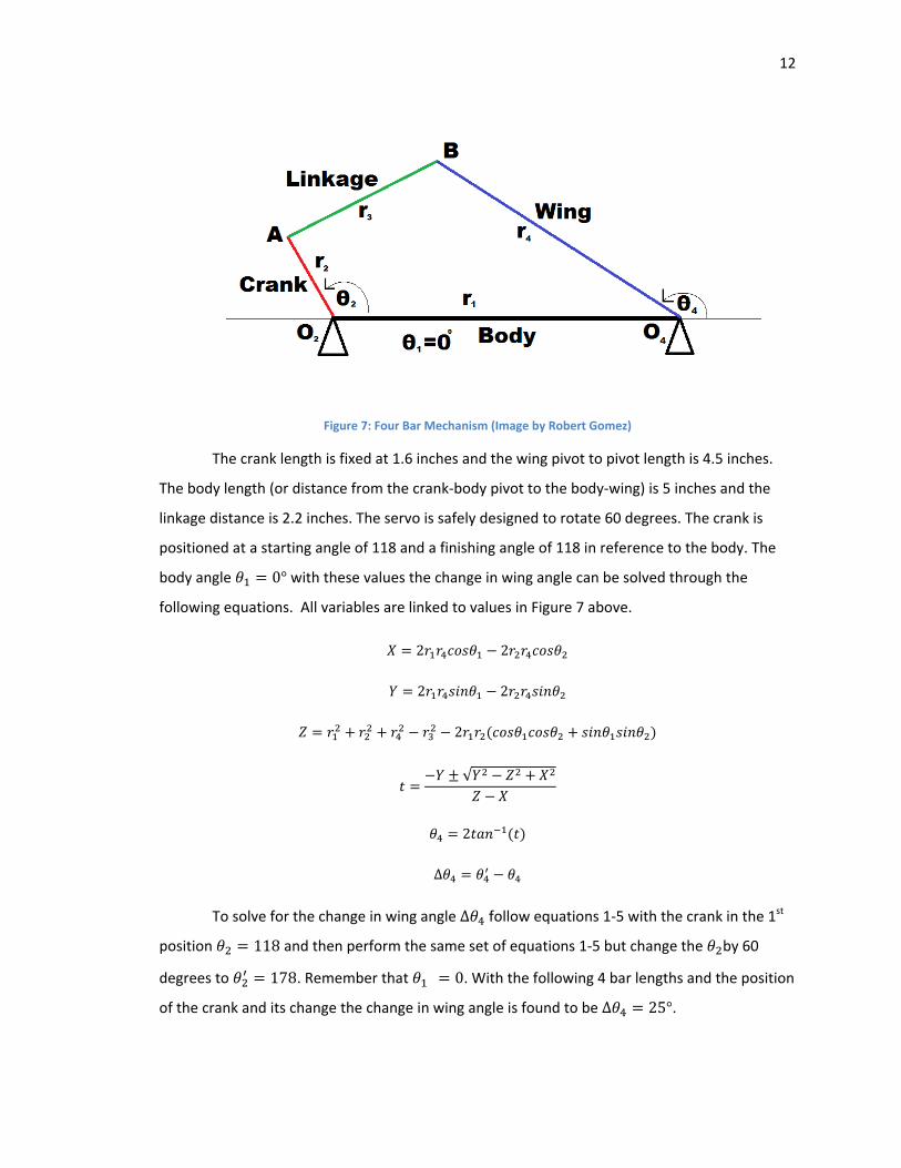
Figure 7: Four Bar Mechanism (Image by Robert Gomez)
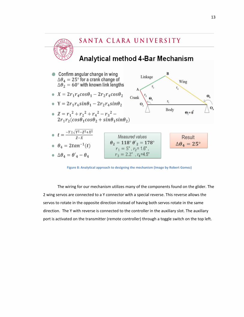
The crank length is fixed at 1.6 inches and the wing pivot to pivot length is 4.5 inches.
The body length (or distance from the crank‐body pivot to the body‐wing) is 5 inches and the
linkage distance is 2.2 inches. The servo is safely designed to rotate 60 degrees. The crank is
positioned at a starting angle of 118 and a finishing angle of 118 in reference to the body. The
body angle 0° with these values the change in wing angle can be solved through the
following equations. All variables are linked to values in Figure 7 above.
2 2
2 2
2
√
2
∆
To solve for the change in wing angle ∆ follow equations 1‐5 with the crank in the 1st
position 118 and then perform the same set of equations 1‐5 but change the by 60
degrees to 178. Remember that 0. With the following 4 bar lengths and the position
of the crank and its change the change in wing angle is found to be ∆ 25°.
13
Figure 8: Analytical approach to designing the mechanism (Image by Robert Gomez)
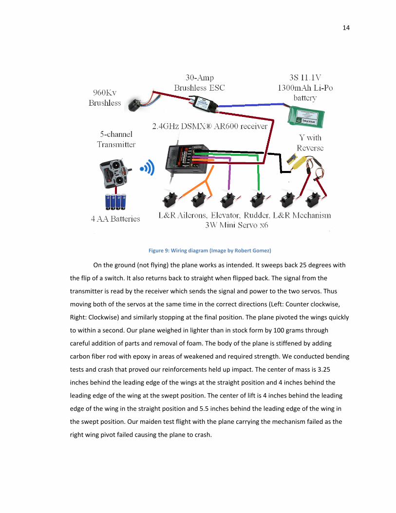
The wiring for our mechanism utilizes many of the components found on the glider. The
2 wing servos are connected to a Y connector with a special reverse. This reverse allows the
servos to rotate in the opposite direction instead of having both servos rotate in the same
direction. The Y with reverse is connected to the controller in the auxiliary slot. The auxiliary
port is activated on the transmitter (remote controller) through a toggle switch on the top left.
14
Figure 9: Wiring diagram (Image by Robert Gomez)
On the ground (not flying) the plane works as intended. It sweeps back 25 degrees with
the flip of a switch. It also returns back to straight when flipped back. The signal from the
transmitter is read by the receiver which sends the signal and power to the two servos. Thus
moving both of the servos at the same time in the correct directions (Left: Counter clockwise,
Right: Clockwise) and similarly stopping at the final position. The plane pivoted the wings quickly
to within a second. Our plane weighed in lighter than in stock form by 100 grams through
careful addition of parts and removal of foam. The body of the plane is stiffened by adding
carbon fiber rod with epoxy in areas of weakened and required strength. We conducted bending
tests and crash that proved our reinforcements held up impact. The center of mass is 3.25
inches behind the leading edge of the wings at the straight position and 4 inches behind the
leading edge of the wing at the swept position. The center of lift is 4 inches behind the leading
edge of the wing in the straight position and 5.5 inches behind the leading edge of the wing in
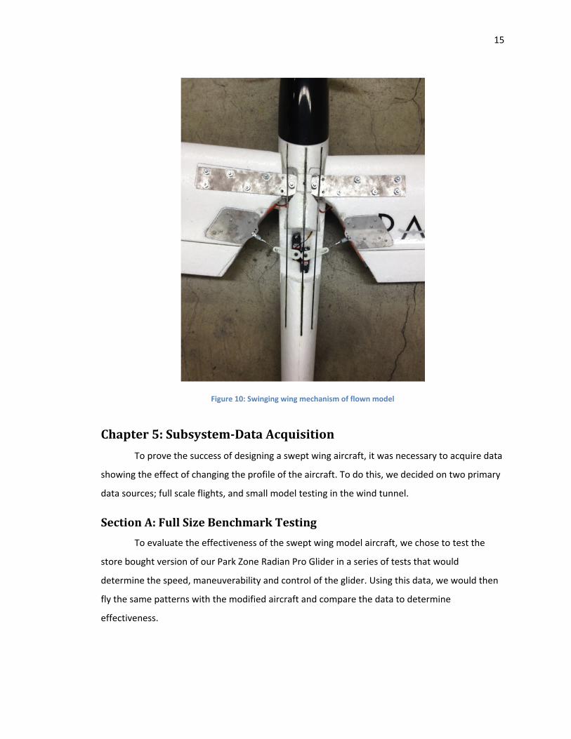
the swept position. Our maiden test flight with the plane carrying the mechanism failed as the
right wing pivot failed causing the plane to crash.
15
Figure 10: Swinging wing mechanism of flown model
Chapter5:Subsystem‐DataAcquisition
To prove the success of designing a swept wing aircraft, it was necessary to acquire data
showing the effect of changing the profile of the aircraft. To do this, we decided on two primary
data sources; full scale flights, and small model testing in the wind tunnel.
SectionA:FullSizeBenchmarkTesting
To evaluate the effectiveness of the swept wing model aircraft, we chose to test the
store bought version of our Park Zone Radian Pro Glider in a series of tests that would
determine the speed, maneuverability and control of the glider. Using this data, we would then
fly the same patterns with the modified aircraft and compare the data to determine
effectiveness.
16
The first of the three tests was the velocity test. This test was a straight flight between
two cones 100 yards apart with the glider a level distance off the ground. The plane was at full
throttle during this test, assuming it would be the maximum velocity of level flight for the craft.
Personnel stood at either cone with raised arms. When the aircraft flew over them they would
lower their arm, signaling that the aircraft had passed overhead. Timers stood at a neutral
position allowing for clear and accurate measurements. Multiple passes of the distance allowed
for an average time of high certainty. Using these times, and a known distance, we were able to
calculate the velocity of the aircraft.
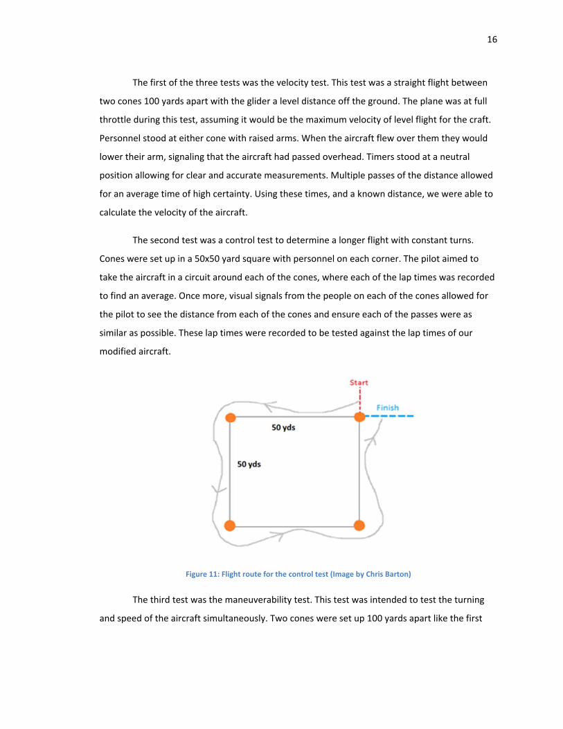
The second test was a control test to determine a longer flight with constant turns.
Cones were set up in a 50x50 yard square with personnel on each corner. The pilot aimed to
take the aircraft in a circuit around each of the cones, where each of the lap times was recorded
to find an average. Once more, visual signals from the people on each of the cones allowed for
the pilot to see the distance from each of the cones and ensure each of the passes were as
similar as possible. These lap times were recorded to be tested against the lap times of our
modified aircraft.
Figure 11: Flight route for the control test (Image by Chris Barton)
The third test was the maneuverability test. This test was intended to test the turning
and speed of the aircraft simultaneously. Two cones were set up 100 yards apart like the first
17
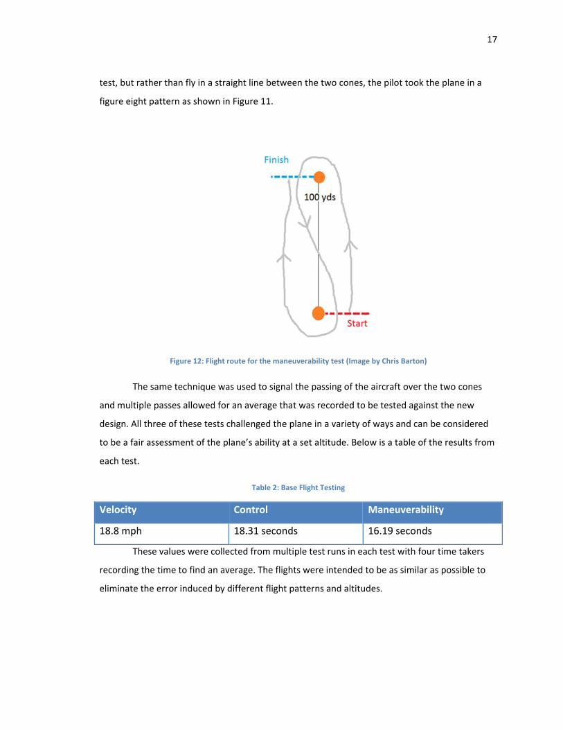
test, but rather than fly in a straight line between the two cones, the pilot took the plane in a
figure eight pattern as shown in Figure 11.
Figure 12: Flight route for the maneuverability test (Image by Chris Barton)
The same technique was used to signal the passing of the aircraft over the two cones
and multiple passes allowed for an average that was recorded to be tested against the new
design. All three of these tests challenged the plane in a variety of ways and can be considered
to be a fair assessment of the plane’s ability at a set altitude. Below is a table of the results from
each test.
Table 2: Base Flight Testing
Velocity Control Maneuverability
18.8 mph 18.31 seconds 16.19 seconds
These values were collected from multiple test runs in each test with four time takers
recording the time to find an average. The flights were intended to be as similar as possible to
eliminate the error induced by different flight patterns and altitudes.
18
Section B: Wind tunnel Testing
To prove the effectiveness of building a swept wing aircraft, we had to understand the
airplane acted differently when the wings changed position. Our intention was to use the Santa
Clara University wind tunnel to determine the change in drag and lift on the aircraft as the wings
changed position between the horizontal position and the swept position. To do this, our first
challenge was creating scale models of our Radian Pro glider that would fit inside the wind
tunnel and remain proportional to allow for accurate data. Once these models were created, we
needed to create a sting to hold the models in the wind tunnel.
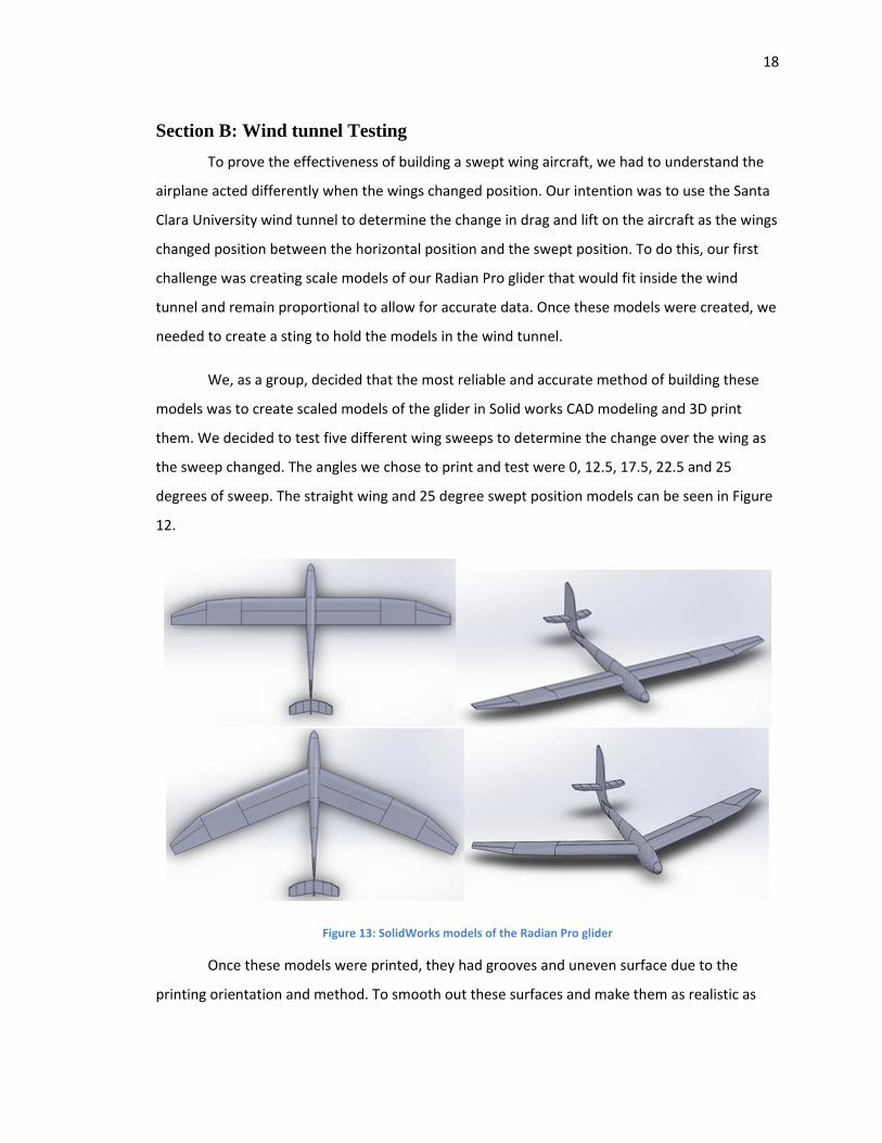
We, as a group, decided that the most reliable and accurate method of building these
models was to create scaled models of the glider in Solid works CAD modeling and 3D print
them. We decided to test five different wing sweeps to determine the change over the wing as
the sweep changed. The angles we chose to print and test were 0, 12.5, 17.5, 22.5 and 25
degrees of sweep. The straight wing and 25 degree swept position models can be seen in Figure
12.
Figure 13: SolidWorks models of the Radian Pro glider
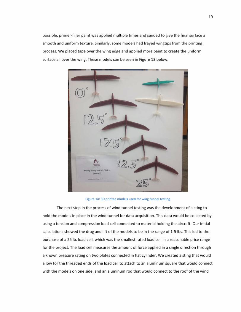
Once these models were printed, they had grooves and uneven surface due to the
printing orientation and method. To smooth out these surfaces and make them as realistic as
19
possible, primer‐filler paint was applied multiple times and sanded to give the final surface a
smooth and uniform texture. Similarly, some models had frayed wingtips from the printing
process. We placed tape over the wing edge and applied more paint to create the uniform
surface all over the wing. These models can be seen in Figure 13 below.
Figure 14: 3D printed models used for wing tunnel testing
The next step in the process of wind tunnel testing was the development of a sting to
hold the models in place in the wind tunnel for data acquisition. This data would be collected by
using a tension and compression load cell connected to material holding the aircraft. Our initial
calculations showed the drag and lift of the models to be in the range of 1‐5 lbs. This led to the
purchase of a 25 lb. load cell, which was the smallest rated load cell in a reasonable price range
for the project. The load cell measures the amount of force applied in a single direction through
a known pressure rating on two plates connected in flat cylinder. We created a sting that would
allow for the threaded ends of the load cell to attach to an aluminum square that would connect
with the models on one side, and an aluminum rod that would connect to the roof of the wind
20
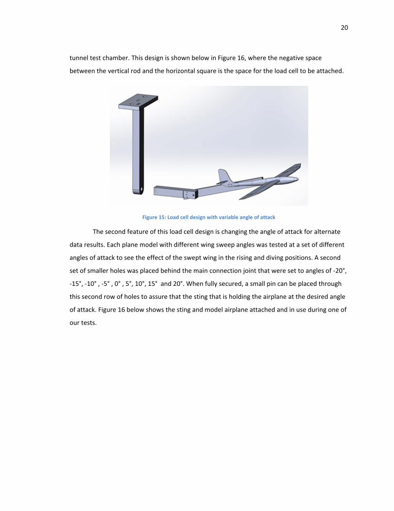
tunnel test chamber. This design is shown below in Figure 16, where the negative space
between the vertical rod and the horizontal square is the space for the load cell to be attached.
Figure 15: Load cell design with variable angle of attack
The second feature of this load cell design is changing the angle of attack for alternate
data results. Each plane model with different wing sweep angles was tested at a set of different
angles of attack to see the effect of the swept wing in the rising and diving positions. A second
set of smaller holes was placed behind the main connection joint that were set to angles of ‐20°,
‐15°, ‐10° , ‐5° , 0° , 5°, 10°, 15° and 20°. When fully secured, a small pin can be placed through
this second row of holes to assure that the sting that is holding the airplane at the desired angle
of attack. Figure 16 below shows the sting and model airplane attached and in use during one of
our tests.
21
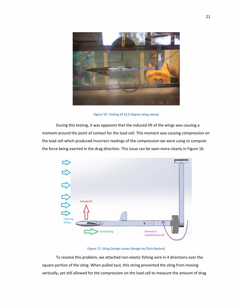
Figure 16: Testing of 12.5 degree wing sweep
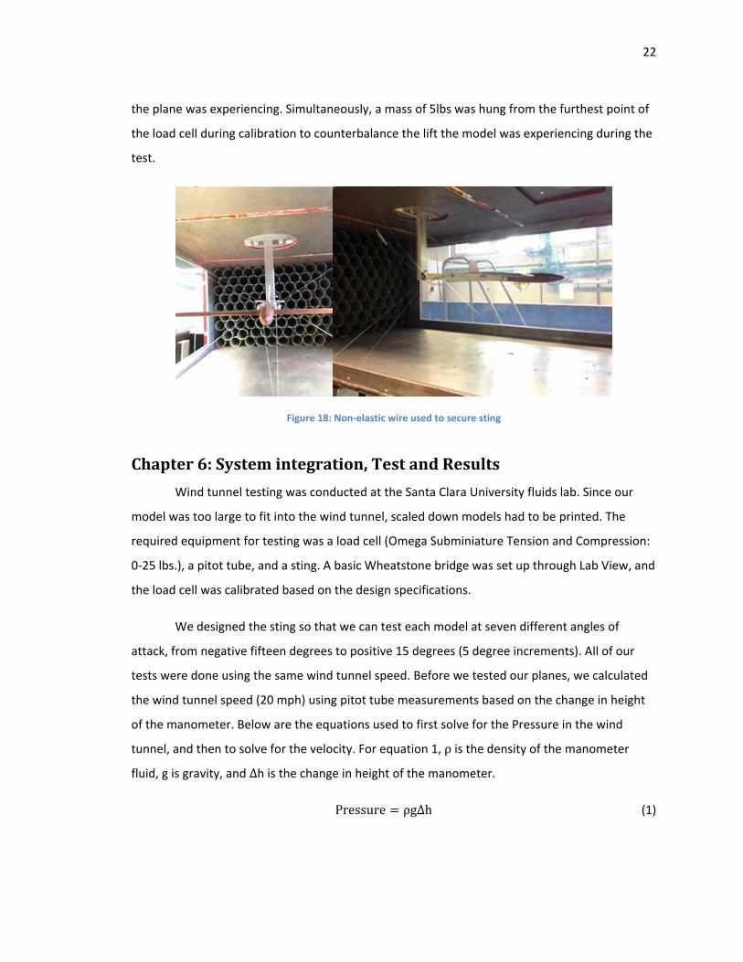
During this testing, it was apparent that the induced lift of the wings was causing a
moment around the point of contact for the load cell. This moment was causing compression on
the load cell which produced incorrect readings of the compression we were using to compute
the force being exerted in the drag direction. This issue can be seen more clearly in Figure 16.
Figure 17: Sting Design Issues (Image by Chris Barton)
To resolve this problem, we attached non‐elastic fishing wire in 4 directions over the
square portion of the sting. When pulled taut, this string prevented the sting from moving
vertically, yet still allowed for the compression on the load cell to measure the amount of drag
22
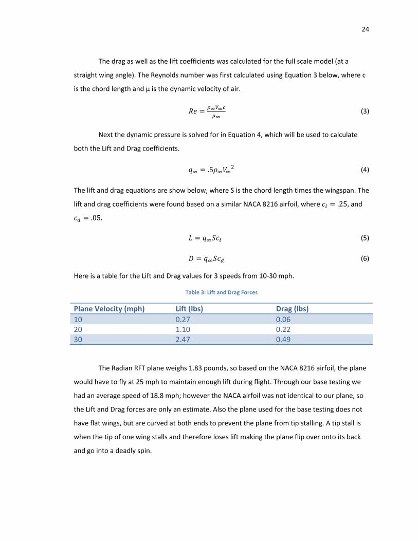
the plane was experiencing. Simultaneously, a mass of 5lbs was hung from the furthest point of
the load cell during calibration to counterbalance the lift the model was experiencing during the
test.
Figure 18: Non‐elastic wire used to secure sting
Chapter6:Systemintegration,TestandResults
Wind tunnel testing was conducted at the Santa Clara University fluids lab. Since our
model was too large to fit into the wind tunnel, scaled down models had to be printed. The
required equipment for testing was a load cell (Omega Subminiature Tension and Compression:
0‐25 lbs.), a pitot tube, and a sting. A basic Wheatstone bridge was set up through Lab View, and
the load cell was calibrated based on the design specifications.
We designed the sting so that we can test each model at seven different angles of
attack, from negative fifteen degrees to positive 15 degrees (5 degree increments). All of our
tests were done using the same wind tunnel speed. Before we tested our planes, we calculated
the wind tunnel speed (20 mph) using pitot tube measurements based on the change in height
of the manometer. Below are the equations used to first solve for the Pressure in the wind
tunnel, and then to solve for the velocity. For equation 1, ρis the density of the manometer
fluid, g is gravity, and Δh is the change in height of the manometer.
Pressure ρgΔh (1)
23
Velocity (2)
For each model, starting with the straight wing, data for drag was collected from
LabView for 45 seconds for each angle of attack. Once the data was collected, the model was
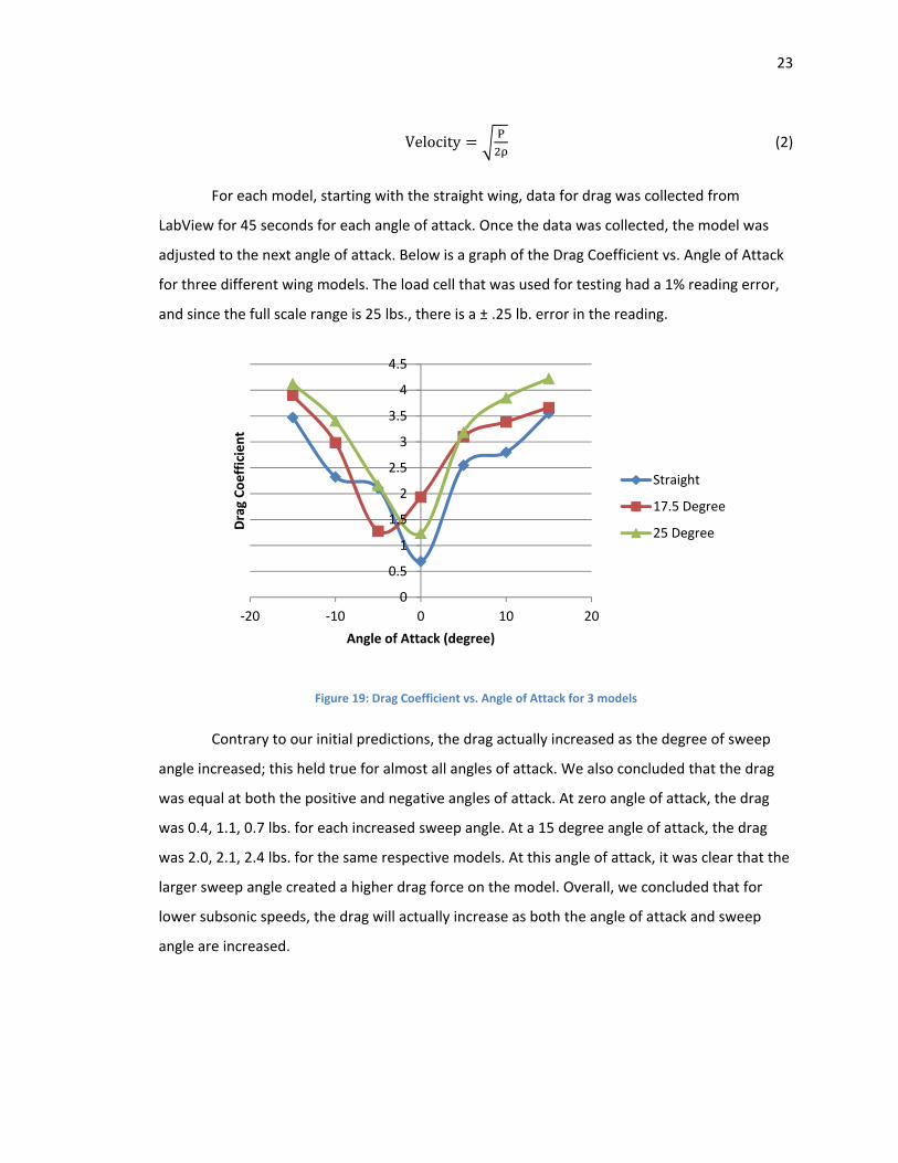
adjusted to the next angle of attack. Below is a graph of the Drag Coefficient vs. Angle of Attack
for three different wing models. The load cell that was used for testing had a 1% reading error,
and since the full scale range is 25 lbs., there is a ± .25 lb. error in the reading.
Figure 19: Drag Coefficient vs. Angle of Attack for 3 models
Contrary to our initial predictions, the drag actually increased as the degree of sweep
angle increased; this held true for almost all angles of attack. We also concluded that the drag
was equal at both the positive and negative angles of attack. At zero angle of attack, the drag
was 0.4, 1.1, 0.7 lbs. for each increased sweep angle. At a 15 degree angle of attack, the drag
was 2.0, 2.1, 2.4 lbs. for the same respective models. At this angle of attack, it was clear that the
larger sweep angle created a higher drag force on the model. Overall, we concluded that for
lower subsonic speeds, the drag will actually increase as both the angle of attack and sweep
angle are increased.
0
0.5
1
1.5
2
2.5
3
3.5
4
4.5
‐20 ‐10 0 10 20
Drag Coefficient
Angle of Attack (degree)
Straight
17.5 Degree
25 Degree
24
The drag as well as the lift coefficients was calculated for the full scale model (at a
straight wing angle). The Reynolds number was first calculated using Equation 3 below, where c
is the chord length and μ is the dynamic velocity of air.
(3)
Next the dynamic pressure is solved for in Equation 4, which will be used to calculate
both the Lift and Drag coefficients.
.5 (4)
The lift and drag equations are show below, where S is the chord length times the wingspan. The
lift and drag coefficients were found based on a similar NACA 8216 airfoil, where .25, and
.05.
(5)
(6)
Here is a table for the Lift and Drag values for 3 speeds from 10‐30 mph.
Table 3: Lift and Drag Forces
Plane Velocity (mph) Lift (lbs) Drag (lbs)
10 0.27 0.06 20 1.10 0.22 30 2.47 0.49
The Radian RFT plane weighs 1.83 pounds, so based on the NACA 8216 airfoil, the plane
would have to fly at 25 mph to maintain enough lift during flight. Through our base testing we
had an average speed of 18.8 mph; however the NACA airfoil was not identical to our plane, so
the Lift and Drag forces are only an estimate. Also the plane used for the base testing does not
have flat wings, but are curved at both ends to prevent the plane from tip stalling. A tip stall is
when the tip of one wing stalls and therefore loses lift making the plane flip over onto its back
and go into a deadly spin.
25
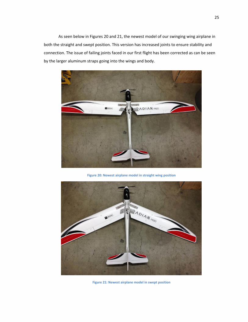
As seen below in Figures 20 and 21, the newest model of our swinging wing airplane in
both the straight and swept position. This version has increased joints to ensure stability and
connection. The issue of failing joints faced in our first flight has been corrected as can be seen
by the larger aluminum straps going into the wings and body.
Figure 20: Newest airplane model in straight wing position
Figure 21: Newest airplane model in swept position
26
Chapter7:CostAnalysis
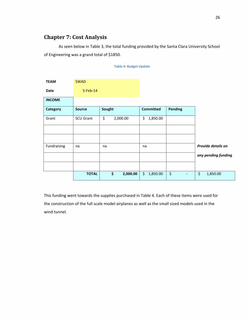
As seen below in Table 3, the total funding provided by the Santa Clara University School
of Engineering was a grand total of $1850.
Table 4: Budget Update
TEAM SWAD
Date 5‐Feb‐14
INCOME
Category Source Sought Committed Pending
Grant SCU Grant $ 2,000.00 $ 1,850.00
Fundraising na na na Provide details on
any pending funding
TOTAL $ 2,000.00 $ 1,850.00 $ ‐ $ 1,850.00
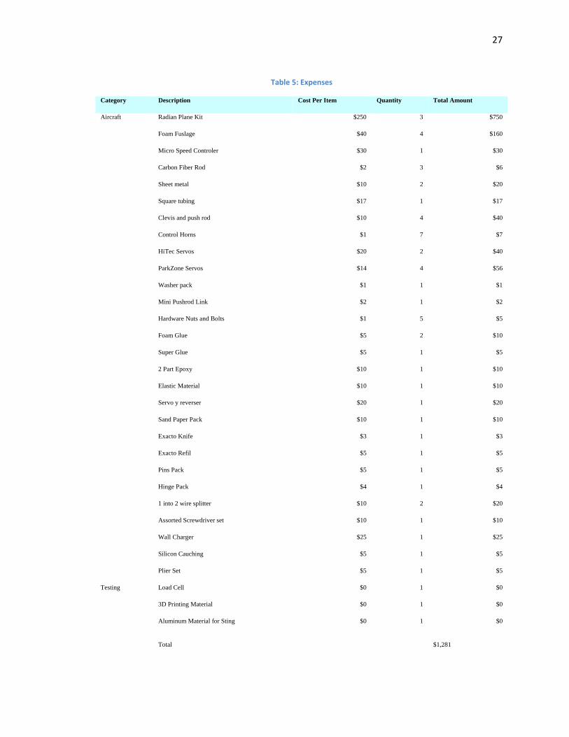
This funding went towards the supplies purchased in Table 4. Each of these items were used for
the construction of the full scale model airplanes as well as the small sized models used in the
wind tunnel.
27
Table 5: Expenses
Category Description Cost Per Item Quantity Total Amount
Aircraft Radian Plane Kit $250 3 $750
Foam Fuslage $40 4 $160
Micro Speed Controler $30 1 $30
Carbon Fiber Rod $2 3 $6
Sheet metal $10 2 $20
Square tubing $17 1 $17
Clevis and push rod $10 4 $40
Control Horns $1 7 $7
HiTec Servos $20 2 $40
ParkZone Servos $14 4 $56
Washer pack $1 1 $1
Mini Pushrod Link $2 1 $2
Hardware Nuts and Bolts $1 5 $5
Foam Glue $5 2 $10
Super Glue $5 1 $5
2 Part Epoxy $10 1 $10
Elastic Material $10 1 $10
Servo y reverser $20 1 $20
Sand Paper Pack $10 1 $10
Exacto Knife $3 1 $3
Exacto Refil $5 1 $5
Pins Pack $5 1 $5
Hinge Pack $4 1 $4
1 into 2 wire splitter $10 2 $20
Assorted Screwdriver set $10 1 $10
Wall Charger $25 1 $25
Silicon Cauching $5 1 $5
Plier Set $5 1 $5
Testing Load Cell $0 1 $0
3D Printing Material $0 1 $0
Aluminum Material for Sting $0 1 $0
Total $1,281
28
Chapter8:BusinessPlan
RC gliders only have one flight position. Their wings are not able to pivot back to a faster
more aerodynamic flight position. We will create a small kit that will easily allow anyone to
convert their ordinary RC glider into a multi‐position glider. This kit can be purchased at our
website along with many hobby shops in the area. This kit is easy to use and has directions how
to implement this change on your glider. With all the parts, the user can change its plane and be
ready to fly in no time.
There is a very large market for model planes. Many people enjoy making and flying
their model airplanes. The model airplane we used in particular was a remote control glider.
These gliders are very lightweight and are easy to control. However, one problem is that none of
these gliders has two flight modes. Our model is able to sweep its wings from a straight wing
position to a swept wing position. This allows the plane to have multiple flight characteristics.
Our plan is to create and sell a conversion kit for ordinary RC gliders. This kit will allow the user
to manipulate their ordinary RC glider in order to sweep its wings to have two different flight
positions. This will generate interest in the RC flying community. With no other product out
there similar to ours, if it generates enough interest it has potential to become a great product.
Our goal is to provide an easy to use kit that can be implemented on any RC glider. This
kit will allow the wings to sweep back enabling the glider to have two different flight modes. We
will sell these kits to RC glider hobbyists. Our kit includes multiple parts already machined that
will be used to change any ordinary plane to a plane with two wing positions. The kit includes
machined steel sheet metal, assorted lengths of carbon fiber, a few nuts and bolts, a center
aluminum frame, and a servo splitter with reverse to allow for equal pivoting for each wing. The
kit will also come with a set of directions describing how to assemble these parts onto the glider.
There is no current competition for this product. Because no gliders do this there is no
competition for this product. We will be the sole provider for this particular product. First we
plan to sell our kit in local hobby shops. This will get the word out to all of the local enthusiasts
about our product. Another goal we have would be to connect with a specific model and be able
to sell our kit with that specific model. This way when people are ordering online there will be a
box to order our kit with the plane. For more of an incentive there will be a discount if you order
29
the product with the plane. If there is success in selling it with one model we will begin to add
the kit to other models as well.
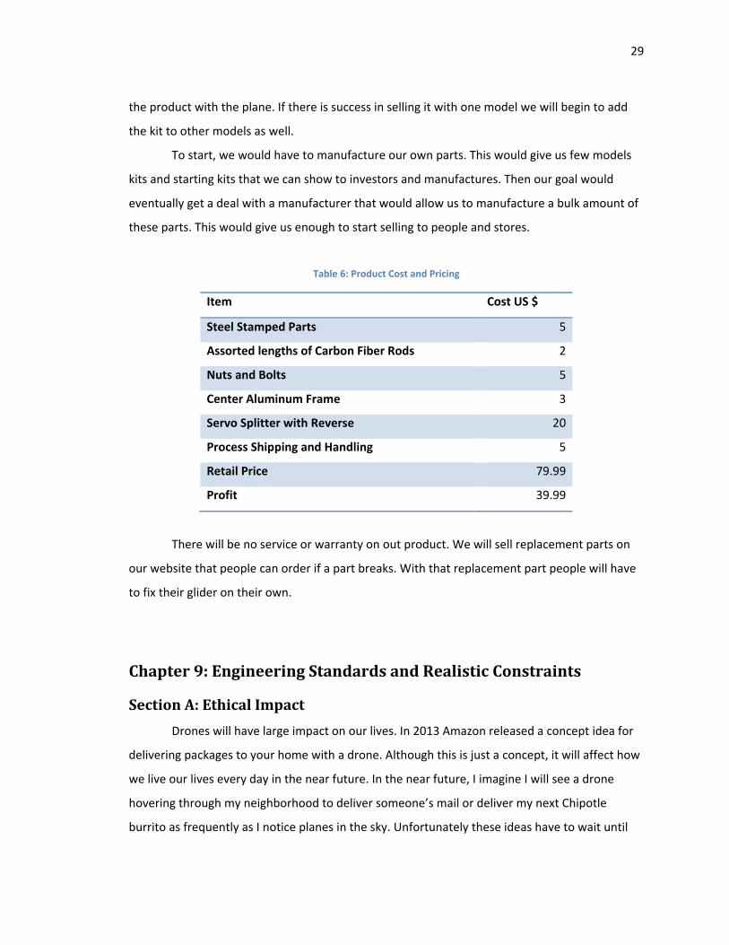
To start, we would have to manufacture our own parts. This would give us few models
kits and starting kits that we can show to investors and manufactures. Then our goal would
eventually get a deal with a manufacturer that would allow us to manufacture a bulk amount of
these parts. This would give us enough to start selling to people and stores.
Table 6: Product Cost and Pricing
Item Cost US $
Steel Stamped Parts 5
Assorted lengths of Carbon Fiber Rods 2
Nuts and Bolts 5
Center Aluminum Frame 3
Servo Splitter with Reverse 20
Process Shipping and Handling 5
Retail Price 79.99
Profit 39.99
There will be no service or warranty on out product. We will sell replacement parts on
our website that people can order if a part breaks. With that replacement part people will have
to fix their glider on their own.
Chapter9:EngineeringStandardsandRealisticConstraints
SectionA:EthicalImpact
Drones will have large impact on our lives. In 2013 Amazon released a concept idea for
delivering packages to your home with a drone. Although this is just a concept, it will affect how
we live our lives every day in the near future. In the near future, I imagine I will see a drone
hovering through my neighborhood to deliver someone’s mail or deliver my next Chipotle
burrito as frequently as I notice planes in the sky. Unfortunately these ideas have to wait until
30
2015 when new guidelines are to be released regarding drone usage. Until recently, the Federal
Aviation Administration (FAA) has scared companies out of using drones by prohibiting the
commercial use of drones by issuing a policy statement in 2007. This statement did not make it
into federal law because it did not go through the correct avenues in law. A Judge from the
National Transportation Safety Board has dismissed a case in which the FAA fined a drone
operator $10,000 for using a drone to record a promotional video for his school. This means that
the judge decided that since the statement by the FAA did not make it into federal law and so
the FAA has no authority over small unmanned aircraft. This now has opened the skies up for
commercial use. The space up for grabs right now, classified as Class G, is reserved from 700 ft ‐
1200 ft above the ground level (not sea level). So, cities like Denver still have air space to fly in.
Although commercial drone usage is currently in a legal struggle, the FAA is going to
choose six states to plan how to integrate drones into the national airspace by 2015. It is
estimated that by 2020 there will be over 30,000 drones flying around U.S. airspace. This
dramatic increase in drone usage is raising many safety and privacy concerns among some
lawmakers and the public. Some drones, particularly those used for law enforcement, will have
thermal imaging technology that can see within the typical home, which is a scary thought for
many Americans, who feel it is an unnecessary invasion of privacy.
SectionB:EnvironmentalImpact
This project can have multiple environmental impacts, some good and some bad.
Common customers who use this type of glider are ranchers, farmers, and big landowners. They
use these gliders to monitor their land easily and effectively. Normally these farmers would have
to fly over their crops with a manned airplane or helicopter, which is very expensive and time
consuming. Flying the manned aircrafts to check on crops costs about $1000 per hour, where
using one of the gliders will cost under $50 per hour. This will save thousands of dollars per year
while still being able to regulate the crops and livestock properly. If the gliders power source is a
battery, this will help the environment as well. The current planes used for flyovers to check on
crops are powered by fuel and removing these from the sky will eliminate a large portion of
pollution caused by current practices.
31
Another impact drones can have on the environment is the protection of wildlife and
the tracking of poachers and others who intend to harm endangered species. There are many
endangered species in the wild that need protection, however there are not enough people able
to monitor these animals and protect them from poachers at all times. With relatively cheap
drones, wildlife activists can perform routine sweeps of the wildlife in their natural habitat
without interfering with the animals. This same system can also track poachers hunting these
endangered animals and alert authorities in a timely manner. This can save hundreds of animals
per year and even prevent the eradication of an entire species.
SectionC:Manufacturability
The SWAD plane is designed with manufacturability in mind. The Swing Wing Drone
starts off as a Ready to Fly RC Glider from ParkZone. Some of the key highlights are, the drone
incorporates many of the already existing components on the glider, and many affordable off
the shelf parts are used, 4 custom parts are made in house with simple sheet metal fabrication
and milling techniques. Assembly does not require a special tool just what is in your standard
hobby tool box.
The idea from the beginning was to make is easy to fabricate. To start we kept the
number of new parts to a minimum. For example, the planes 2 auxiliary flap servos were reused
as the plane’s wing mechanism servos. This saved us from having to make a servo or find one
from off the shelf. The ParkZone brand makes much replacement part for their products and
keeps the prices lower than the competition by an average of 15%.
The SWAD plane has 4 custom parts. The Wing Brace 4x and Wing Control Horn 2x are
both made of 22 gauge steel and fabricated using a sheet metal break and drill press. This
manufacturing technique is simple but in efficient in time. To manufacture both of these parts
efficiently a press or plasma cutter would work fine for mass manufacturability. The Center
Square 1x is the pivot piece for the mechanism. It is manufactured with a milling machine and a
drill press. The milling machine uses one bit and a jig for accurate cuts. The milling machine is
programed to cut in a simple arc path. The drill press is required to make straight through holes.
The fourth part, Spacers 4x, are cut with a hack saw to length. All the parts can be assembled
with a standard hobby box (screwdriver set, Foam Glue, epoxy, and X‐Acto knife).
32
SectionD:SocialImpact
Recently there are many social implications dealing with commercial drones. Next year
congress is passing a new bill with the FAA expanding the space where drones will be able to fly.
Drones will be able to fly with airliners, cargo planes and private aircrafts, as opposed to
designated areas that are nowhere near airports3. This brings up some issues with the public
because people may react differently to this situation. With more drones in the air there is a
better chance they will crash and cause damage on the ground. Now drones are not supposed
to crash and this has happened only a few times, but with more drones in the sky there is more
of a chance for problems.
Another effect this new law will have on people is the privacy aspect of their social lives.
Many people attach cameras or some sort of recording device on their drones so they can see
when the drones are far away. This can bring about spying on people. With drones that can fly
high in the air and cameras that can zoom in so well, people can be spied on without even
knowing it. US citizens do not like being watched without their knowledge. This is a violation of
people’s privacy. Although having more drones in the air has the potential to help with crime
and law breaking, is it worth it to have people “spying” on you when you are in public? Some
people believe that this would be a good thing, and others disagree.
One good application regarding drones and social use is through the operations of
servicemen. Servicemen such as policemen and firefighters have many applications that they
could use drones for. They can use drones to help keep our society safe. The policemen can use
drones in an unsafe situation to gain a tactical advantage over their assailant4. This way they can
apprehend the person with as little damage as possible. The firefighters can use the drones to
quickly get an aerial view of a fire that they are fighting. The way they can strategize and get a
good plan right away. This would be a cheap and effective way to fight fires.
3 "Drones Will Be Admitted to Standard US Airspace By 2015." Popular Science. N.p., n.d. Web. 08 June 2014. 4 "Social Issues ‐ In Drones We Trust." Social Issues ‐ In Drones We Trust. N.p., n.d. Web. 08 June 2014.
33
SectionE:EconomicImpact
The uses of drones in the economic world are nearly unlimited with automation and
reliability changing nearly every market to which they are applied. With the upcoming law
changes of American airspace, the FAA has a difficult task of determining exactly where and how
drones can be flown. Currently many hobbyists fly drones through virtual glasses that allow for
birds eye view of the area, however take this exact same drone and apply an infrared ground
sensor and a surveying company just exponentially increased their services. Companies such as
Amazon have already begun testing on a delivery system that will allow for rapid delivery of
reasonably sized good via drone. This same concept has been tossed around with all sorts of
food delivery ranging from quad‐rotor pizza delivery to the “Burrito Bomber,” a Mexican burrito
delivery service that parachutes burritos from a small model airplane to any ordered position5.
The ability to reduce manpower and increase production is a terrifying concept in regards to the
impact it could have on our overall economy. Industries have the potential to change drastically
with the use of drones and there is usual hidden gem of new ways drones could be used to
boom or bust any industry. Our project assists in the study of small winged craft and the effects
of changing a planes profile in flight. When this knowledge is applied to a fleet of delivery
aircraft to drastically reduce the amount of battery required for each delivery, once more the
effectiveness of that system would increase. The total alteration of Amazon delivery going from
trucks and personal/mail delivery, to unmanned flying equipment would be drastic. This is only
one example of the many ways drones could be applied to affect the economy.
Chapter10:SummaryandConclusion
After design, analysis, and testing, a final design of the drone was completed. This
design had a wing with two different flight positions. The first flight position was in the straight
wing position. This would give the plane more stability at slower speeds. The other flight
position has wings swept back 25 degrees. This initially was to help improve the flight
characteristics in the plane, allowing it to be more aerodynamic during flight, and decreasing the
drag on the plane. Wind tunnel tests needed to be done. The model was too big to fit into the
wind tunnel, so smaller models were created. We used Solid Works to create a scaled replica of
5 "Watch A Drone Deliver A Pizza To A Skyscraper In Mumbai." Io9. N.p., n.d. Web. 08 June 2014.
34
our big model that fit into the wind tunnel. Then, we used the solid works file to 3D print
physical models. A straight wing model, and 12.5, 17.5, 22.5, 25 degree wing sweep models
were printed. Then, we created a sting to hold the model in place in the wind tunnel. Tests were
done in the wind tunnel on models with a straight wing, a wing swept 17.5° and a wing swept
25°. A strain gage load cell was used to test the compression of the model on the load cell. It
was found that, at a 0 degree angle of attack, the wing swept at 17.5° caused the most drag.
This was not our initial expectation for our outcome. It proved that, at these speeds, when the
wings sweep back, there will be more drag on the plane. For our base flight testing, a final
comparison was not concluded because our new swing wing plane failed to maintain flight. Our
mechanism proved to be too weak at the joint between the wings and the fuselage, a new
version was built as seen in Figure 21.
35
References
1. "From the Burrito Bomber to Crop Monitoring, a Look at Commercial Drone Use." The Drone Project. Web. 08 June 2014.
2. Anderson, John David. Introduction to Flight. New York: McGraw Hill, 2012. Print.
3. "Drones Will Be Admitted to Standard US Airspace By 2015." Popular Science. Web. 08 June 2014.
4. "Social Issues ‐ In Drones We Trust." Social Issues ‐ In Drones We Trust. Web. 08 June 2014.
5. "Watch A Drone Deliver A Pizza To A Skyscraper In Mumbai." Io9. Web. 08 June 2014.
6. Waldron. K.J., and Kinzel, G.l., Kinematics, Dynamics and Design of Machinery, 2nd ed., Wiley, New Jersey, 2004
36
AppendixA:AdditionalInformationFor additional information see the following sources
http://droneproject.nationalsecurityzone.org/uncertainties-remain-as-faa-integrates-drones-into-
american-skies-josh-solomon/
The FAA has passed a law allowing drones to fly in public airspace in 2015. This could increase
the number of drones to the thousands and many more drones will be seen flying through the air.
http://droneproject.nationalsecurityzone.org/commercial-drone-use-rachel-janik-and-mitchell-
armentrout/
There are many new opportunities for drones out there with the new law about drones. Drones
can be used from delivering fast food to monitoring crops for farmers. This could become a
multimillion dollar industry.
https://www.aclu.org/blog/tag/domestic-drones
With the use of drones increasing in today’s everyday life, a privacy issue arises with local
citizens. There will be a limit to use of drones in surveillance as well as policy that defines drones
specific uses. This is to ensure the safety of US citizens.
http://rt.com/usa/judge-personal-drones-legal-us-310/
The FAA tried to sue and individual for flying his person aircraft close to buildings and cars. They
sued the individual $10,000 for being reckless and careless. This was dismissed because there
are no laws set in place for this particular act.
http://gigaom.com/2013/12/08/so-you-want-to-fly-drones-heres-what-the-law-says/
Airspace is split up into several different classes. Class G which is from the ground to 700 or
1200 feet is unregulated. This is interesting for many hobbyists because there is no set rule in
place for this airspace.
http://droneproject.nationalsecurityzone.org/
Drones are being prepared for many new opportunities with the new laws coming out about
drones in airspace.
37
AppendixB:MachineDrawings
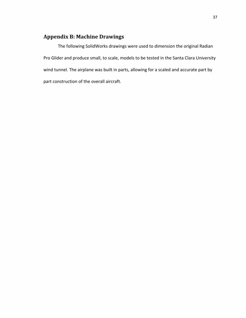
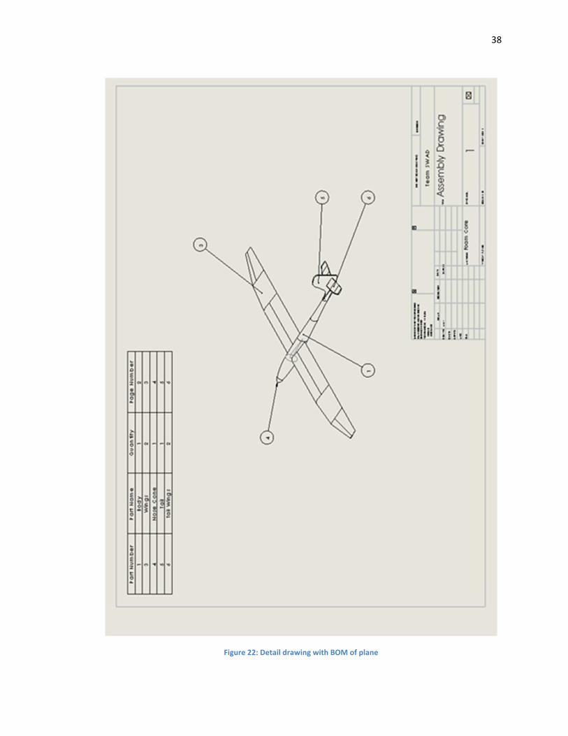
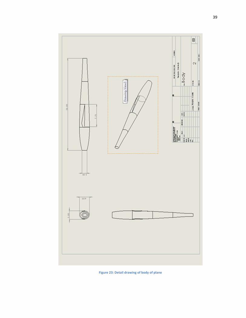
The following SolidWorks drawings were used to dimension the original Radian
Pro Glider and produce small, to scale, models to be tested in the Santa Clara University
wind tunnel. The airplane was built in parts, allowing for a scaled and accurate part by
part construction of the overall aircraft.
38
Figure 22: Detail drawing with BOM of plane
39
Figure 23: Detail drawing of body of plane
40
Figure 24: Detail drawing of nose cone
41
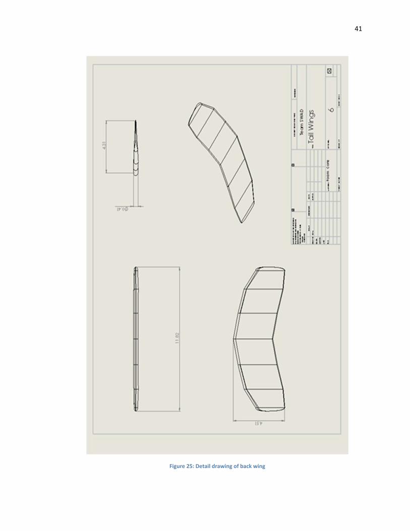
Figure 25: Detail drawing of back wing
42
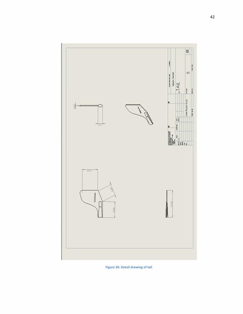
Figure 26: Detail drawing of tail
43
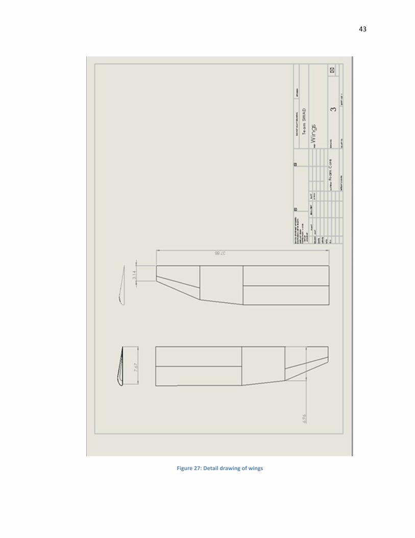
Figure 27: Detail drawing of wings
44
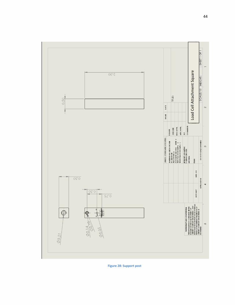
Figure 28: Support post
Load
Cell A
ttachmen
t Square
45
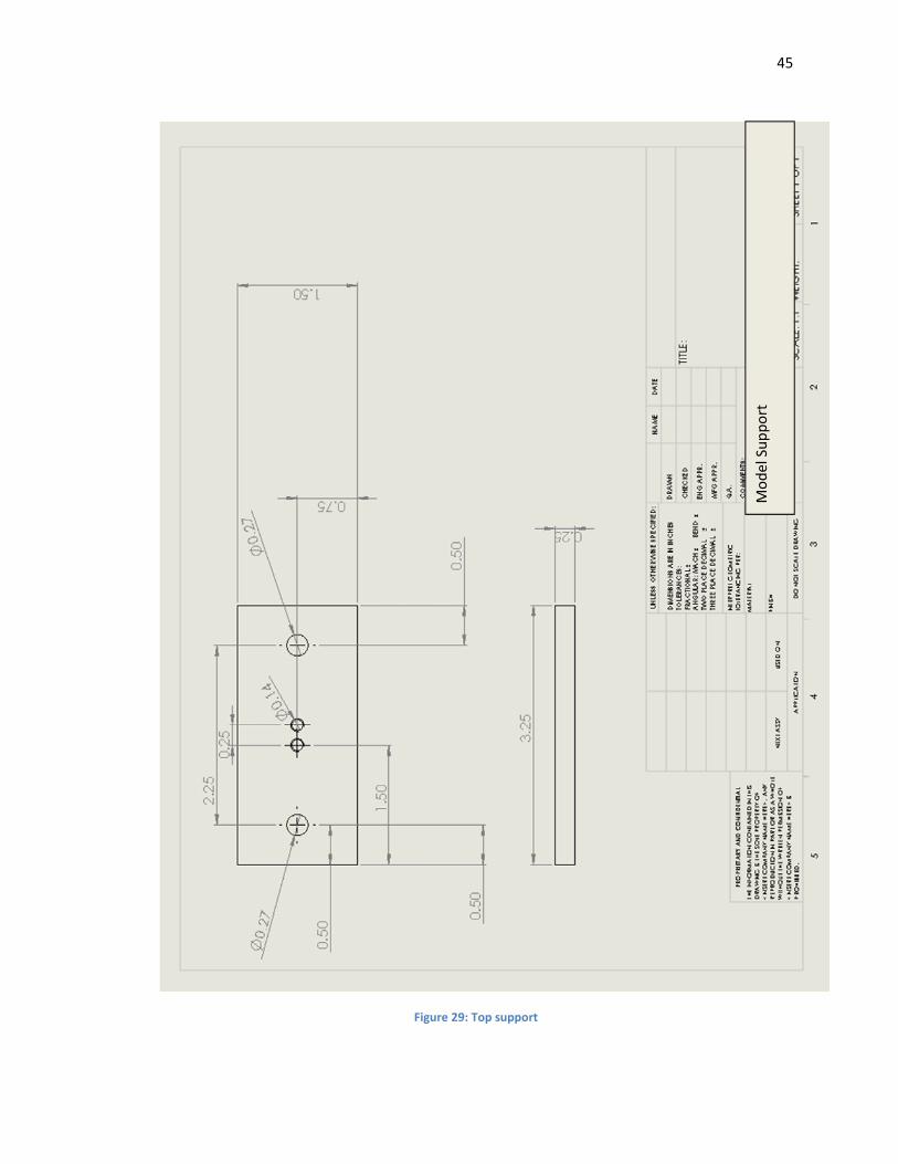
Figure 29: Top support
Model Support
46
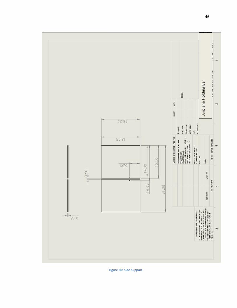
Figure 30: Side Support
Airplane Holding Bar
47
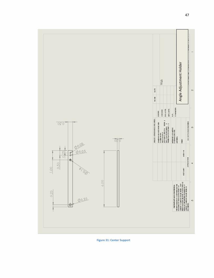
Figure 31: Center Support
Angle Adjustmen
t Holder
48
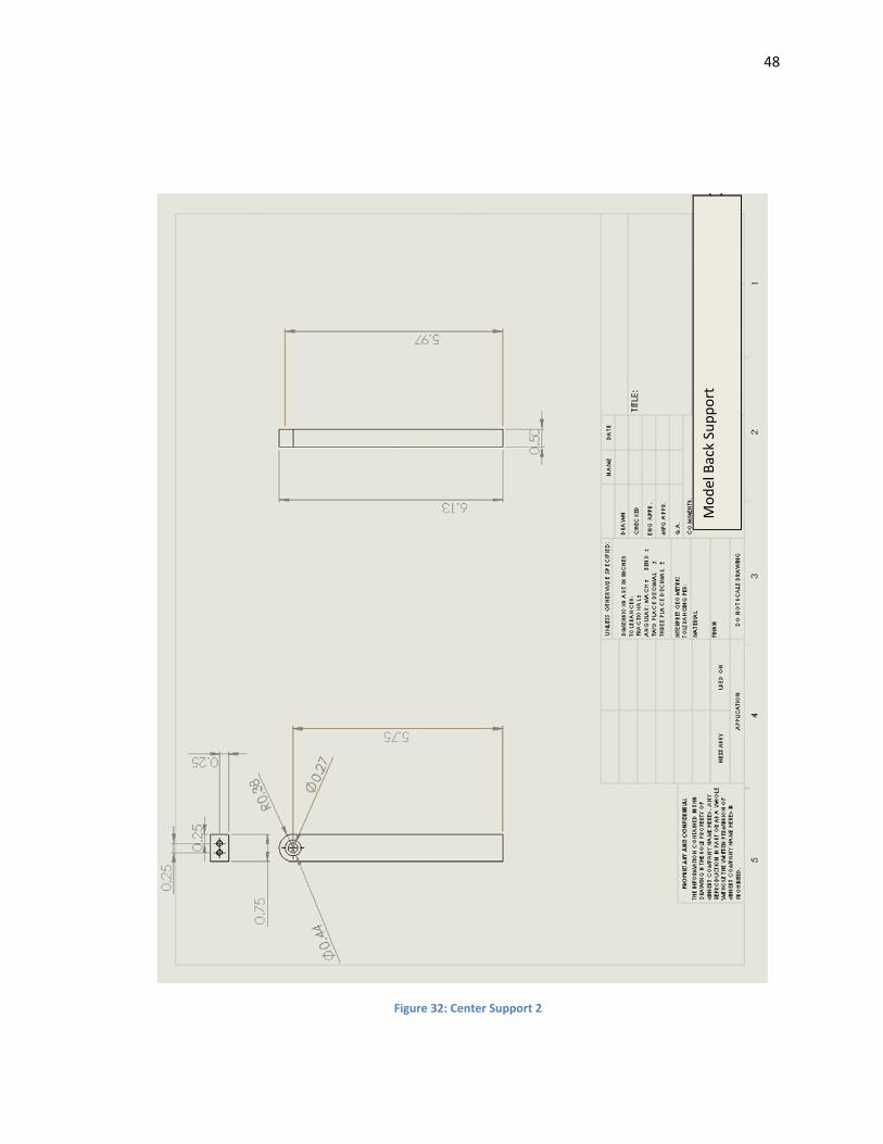
Figure 32: Center Support 2
Model Back Support
49
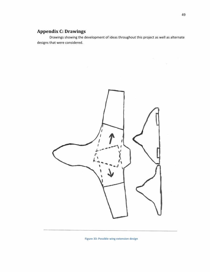
AppendixC:Drawings Drawings showing the development of ideas throughout this project as well as alternate
designs that were considered.
Figure 33: Possible wing extension design
50
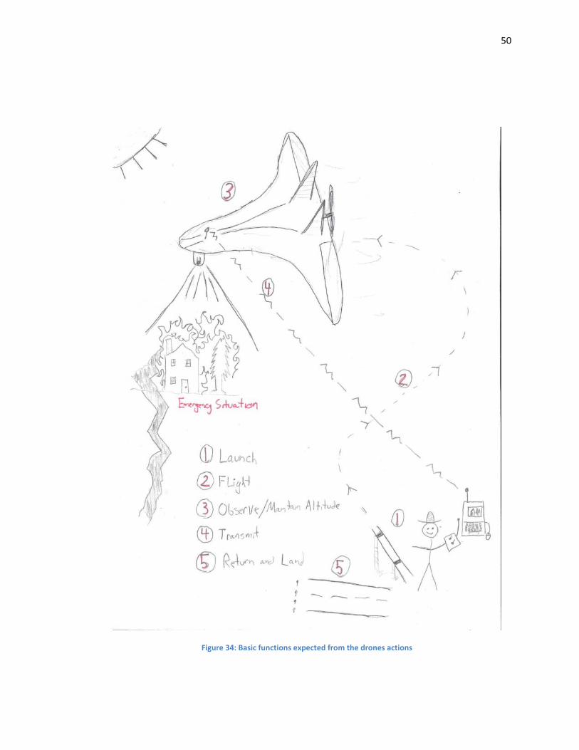
Figure 34: Basic functions expected from the drones actions
51
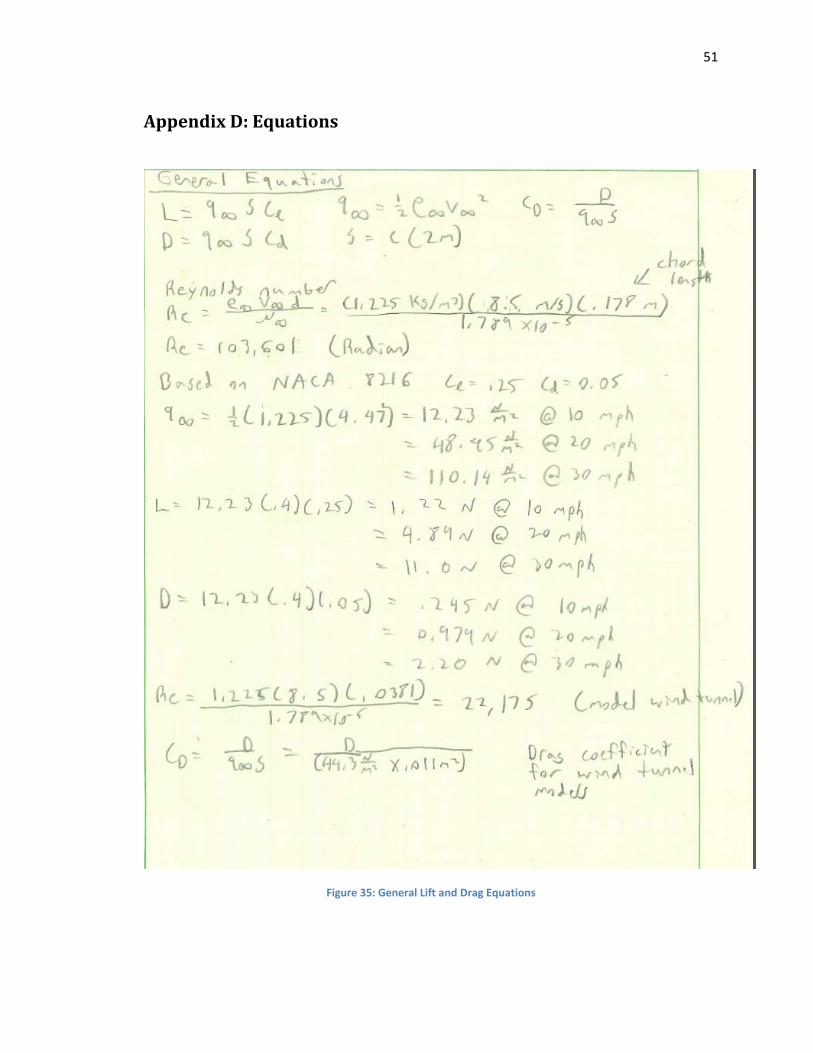
AppendixD:Equations
Figure 35: General Lift and Drag Equations
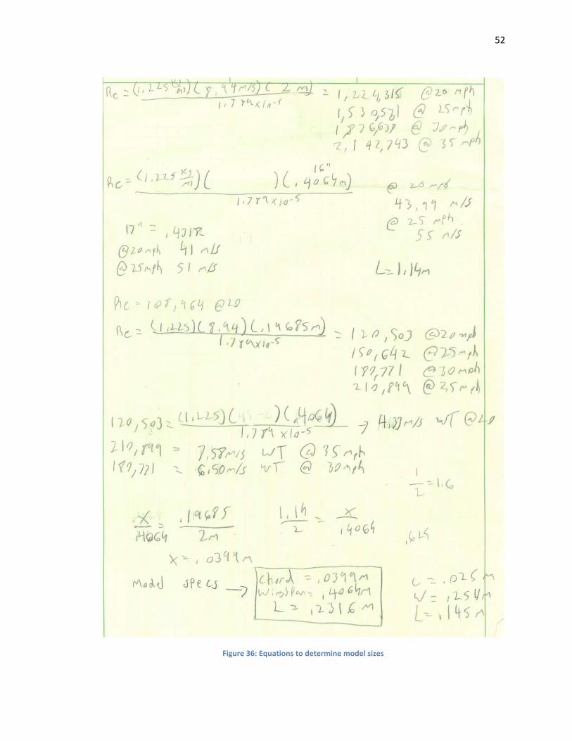
52
Figure 36: Equations to determine model sizes

53
AppendixE:SeniorDesignConferenceSlideshowPresentation
Figure 37: PowerPoint slides 1
54
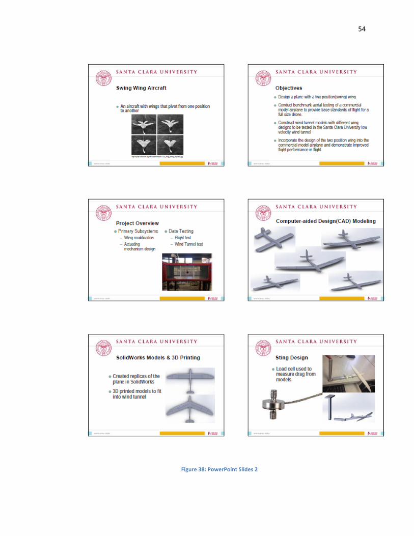
Figure 38: PowerPoint Slides 2
55
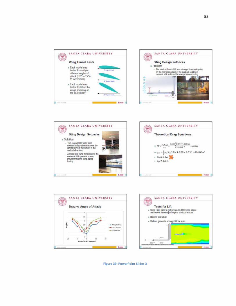
Figure 39: PowerPoint Slides 3
56
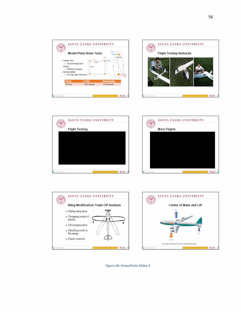
Figure 40: PowerPoint Slides 4
57
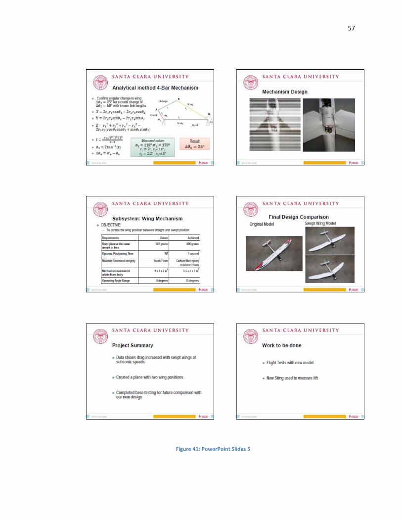
Figure 41: PowerPoint Slides 5
58
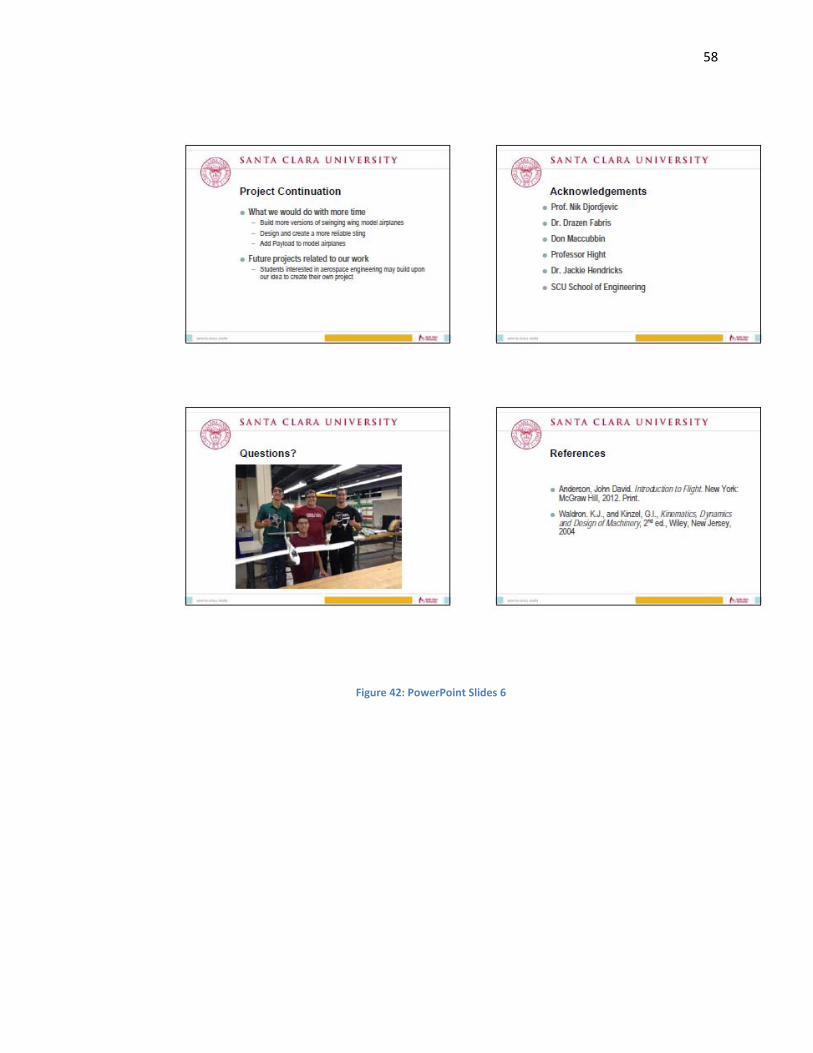
Figure 42: PowerPoint Slides 6
59
AppendixF:TimeLineandGanttCharts
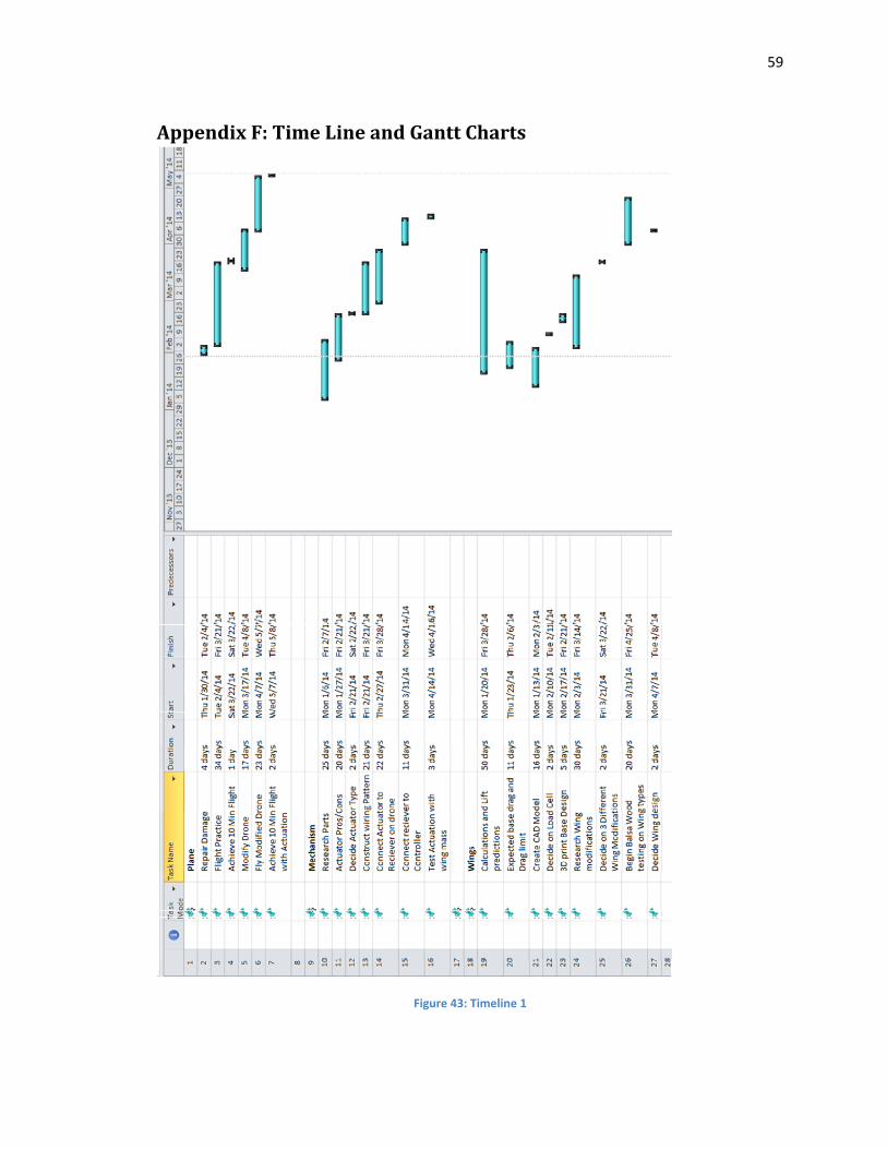
Figure 43: Timeline 1
60
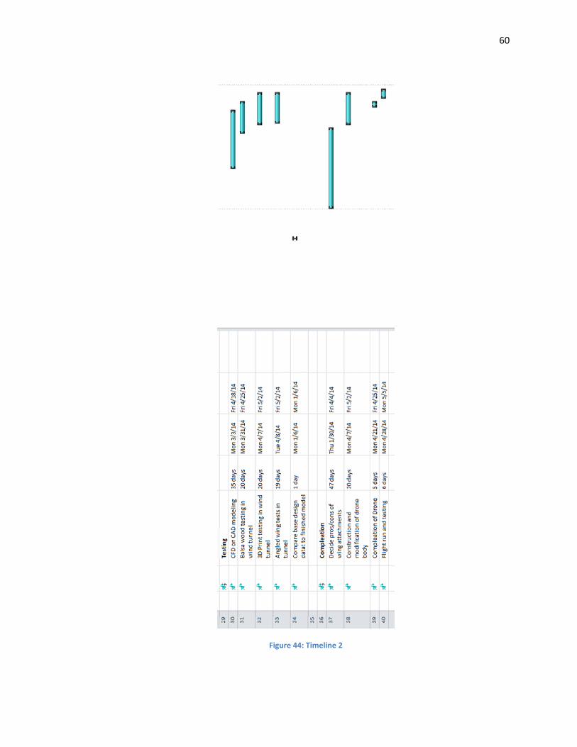
Figure 44: Timeline 2
61
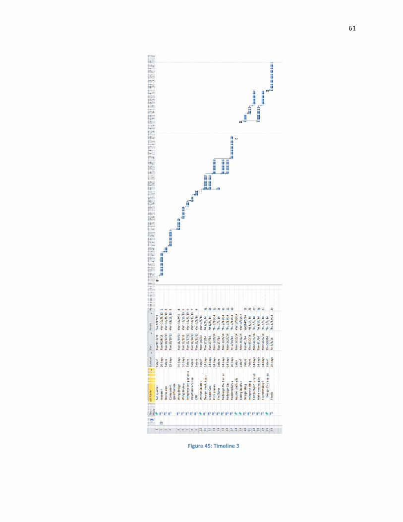
Figure 45: Timeline 3


![SWaD, Seminar and Workshop in Advanced Design [pop-up lecture!!!]](https://img.pdfslide.us/doc/110x75/55b4a6b1bb61ebdc678b4643/swad-seminar-and-workshop-in-advanced-design-pop-up-lecture.jpg)