Embed Size (px)
Citation preview

SWIMMING GOGGLES WITH PROXIMITY SENSORS
Daya Sharon
February 13, 2017

Sharon - 2 -
Contents Abstract ............................................................................................................................................................. - 4 -
Literature Review .............................................................................................................................................. - 5 -
Introduction .................................................................................................................................................. - 5 -
Capacitive Sensors ........................................................................................................................................ - 5 -
Radiofrequency Identification ...................................................................................................................... - 6 -
Displays ......................................................................................................................................................... - 7 -
Heads-Up Display .......................................................................................................................................... - 7 -
Previous Display Methods ............................................................................................................................ - 8 -
Goggle Devices ............................................................................................................................................ - 10 -
Conclusion ................................................................................................................................................... - 12 -
Engineering Plan ......................................................................................................................................... - 12 -
Problem Statement ................................................................................................................................. - 12 -
Engineering Goal ..................................................................................................................................... - 12 -
General Overview of Potential Methods ................................................................................................ - 12 -
Methodology .................................................................................................................................................. - 13 -
Materials ..................................................................................................................................................... - 13 -
Procedure.................................................................................................................................................... - 14 -
Results ............................................................................................................................................................. - 15 -
Data Analysis ................................................................................................................................................... - 16 -
Conclusions ..................................................................................................................................................... - 17 -
Acknowledgements ........................................................................................................................................ - 17 -
References ...................................................................................................................................................... - 18 -
Appendix A ...................................................................................................................................................... - 19 -
Appendix B ...................................................................................................................................................... - 20 -
Arduino Code with LED Modifications ........................................................................................................ - 20 -
Appendix C ...................................................................................................................................................... - 24 -
Limitations and Assumptions ...................................................................................................................... - 24 -
Appendix D ...................................................................................................................................................... - 25 -
Background Notes ....................................................................................................................................... - 25 -

Sharon - 3 -
Ezabella, Brave New World: Rio 2016 Games to showcase technological innovations ......................... - 25 -
Caudell, Augmented Reality: An Application of Heads-Up Display Technology to Manual Manufacturing
Processes ................................................................................................................................................ - 26 -
Hagem, Self-Contained Adaptable Optical Wireless Communications System for Stroke Rate During
Swimming ............................................................................................................................................... - 27 -
Hagem, Coach-Swimmer communications based on wrist mounted 2.4 GHz accelerometer sensor ... - 28 -
Taba, Electronic Timing Swimmer’s Goggles .......................................................................................... - 29 -
Yokota, Swimming Goggles ..................................................................................................................... - 30 -
Hazell, Spectacles with embedded segmented display comprising light guide end............................... - 31 -
Chen, Design and Implementation of capacitive proximity sensor using microelectromechanical systems
technology .............................................................................................................................................. - 32 -
Nath, RFID Technology and Applications ................................................................................................ - 33 -
Schill, Visible Spectrum Optical Communication and Distance Sensing for Underwater Applications .. - 34 -
Schill, Personal Communication.............................................................................................................. - 35 -
Schill, Personal Communication.............................................................................................................. - 36 -

Sharon - 4 -
Abstract
Many swimmers have poor concentration, or poor eyesight, and ultimately obtain injuries by
crashing into the wall of the pool. Radiofrequency identification (RFIDs), the same technology
used in identification cards for business places and schools, was used to provide the wall-
sensing technology. The goal of this project was to engineer a wearable device that alerts a
swimmer as he or she approaches a wall. A test was conducted to find the range of the RFID.
The same test was then conducted in water to confirm that the device would function in a pool.
The device created serves as a model for a crash-prevention device for swimmers. However,
the range of the RFID used in this project was only one to four centimeters. The model could be
modified for use with a longer-ranged RFID. Ranges of around four meters suffice to create a
functional device capable of providing information when the swimmer is far enough from the
wall to comprehend the visual cues from the device.
Sharon - 5 -
Literature Review
Introduction
Many new devices have been created to help athletes improve the quality of their
training. For example, swimmers are now able to listen to music underwater and track their lap
count and heart rate. Some devices even allow swimmers to see their times and stroke rates.
However, not many devices are able to warn a swimmer of an obstacle in his or her way.
Capacitive Sensors
Within the broad category of capacitive sensors, there are two types of sensors:
parallel-plate capacitors and fringe capacitors. Parallel-plate capacitors use two “plates” to
sense the object. The sensor itself is one of the plates and the object is the other plate.
However, parallel-plate capacitors can only be used to sense objects that are conductors.
Fringe capacitors use live electrodes to detect an object. Unlike parallel-plate capacitors, fringe
capacitors do not require the object to be a conductor. (Chen 1998)

Sharon - 6 -
Figure 1. The hierarchy of proximity sensors.
Radiofrequency Identification
Radiofrequency identification is one way to distinguish between objects. The apparatus
uses two parts: a reader and a tag. The tags are passive, meaning they do not transmit any
signal. These tags do not require batteries, can be waterproof, and are very small (Nath 2006).
Many systems today use radiofrequency identification to assist in simple processes. For
example, “EZ-Pass” uses radiofrequency identification to allow for a quicker transition at
tollbooths (Nath 2006). Although radiofrequency identification tags can be waterproof, radio
frequencies do not often travel well through water (Schill 2016). Low frequencies have very
short underwater ranges, and high frequencies have even shorter underwater ranges (Schill
2016).
Proximity Sensors
Capacitive Sensors
Parallel-Plate Capacitors
Fringe CapacitorsRFIDs

Sharon - 7 -
Displays
The display of any device is critical for the device to be functional. Without the display,
the user would not be able to retrieve the feedback that the device is trying to relay. In most
cases, instant feedback is essential for athletes and students in learning and correcting a skill
(Hagem 2015). Whether the display uses light, sound, or vibration, the user must be able to
interpret these transmissions.
Heads-Up Display
One type of display often used in optical devices is the heads-up display. Heads-up
displays work by projecting an image into the field of view of the user. This method creates the
three-dimensional effect that makes heads-up displays similar to holographs in appearance.
Heads-up displays are used by all types of virtual reality goggles to give the user a realistic
experience without making the device too bulky. The visual display used in heads-up displays is
effective for communicating information to the wearer without resorting to color-coding the
information. (Caudell & Mizell, 1992)

Sharon - 8 -
Figure 2. An example of what a heads-up display would look like in a manufacturing setting. (Caudell & Mizell, 1992)
Previous Display Methods
Many devices use a variety of display types. Light emitting diodes have been used with
different colors or intensities to communicate with the user. In a stroke rate sensor, the display
includes three different colors of light emitting diodes. A swimmer is able to preset a goal pace
and the device is able to calculate and display whether the swimmer goes faster than, slower
than, or keeps up with his or her preset pace. The swimmer is able to determine his or her
speed because the display uses a red light emitting diode to indicate that the swimmer is
moving too slow, a blue light emitting diode to indicate that the swimmer is right on track, and

Sharon - 9 -
a green light emitting diode to indicate that the swimmer is moving faster than his/her preset
pace. (Hagem 2013)
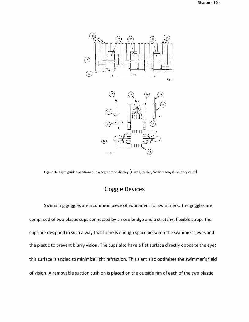
Similarly, a device created by a few British engineers uses optical guides as the display.
The guides are paths that steer the light into the position required for the image that is to be
displayed. The entire display utilizes seven, fourteen, or sixteen guides. The result of the
display is an image that can contain numbers, or a combination of letters and numbers. The
display is also focused at infinity, with the depth of field starting in front of the glasses and
extending to infinity. This method provides a completely transparent display that the wearer
can read and see through at the same time. Heads-up displays can be used in any optical device
that has a clear viewing surface. (Hazell, Millar, Williamson, & Golder, 2006)
Sharon - 10 -
Figure 3. Light guides positioned in a segmented display (Hazell, Millar, Williamson, & Golder, 2006)
Goggle Devices
Swimming goggles are a common piece of equipment for swimmers. The goggles are
comprised of two plastic cups connected by a nose bridge and a stretchy, flexible strap. The
cups are designed in such a way that there is enough space between the swimmer’s eyes and
the plastic to prevent blurry vision. The cups also have a flat surface directly opposite the eye;
this surface is angled to minimize light refraction. This slant also optimizes the swimmer’s field
of vision. A removable suction cushion is placed on the outside rim of each of the two plastic

Sharon - 11 -
cups for comfort. The basic structure of swimming goggles allows the equipment to be used as
a base for many other devices, such as the device described below. (Yokota 2007)
Figure 4. (Left) A front view of a pair of swimming goggles. (Right) A side view of a pair of swimming goggles. (Yokota 2007)
Another electronic timing system uses an accelerometer. The device can measure how
long each swim stroke takes, recognize flip turns, and detect stops. A liquid crystal display is
used in a pair of swimming goggles to show lap counts, total times, split times, and heart rates.
The device shows flashing light emitting diodes when the heart rate increases or decreases.
(Taba 1997)

Sharon - 12 -
Conclusion
Many of the devices that have already been created were designed to assist swimmers
in tracking their training. Regarding displays, heads-up display is an ideal method for displaying
information, but light-emitting diodes are much simpler to use. The timing systems and
accelerometers used in previous devices cannot warn a swimmer of an upcoming wall, but
proximity sensors could help prevent a crash. There is a need for a device that indicates when a
swimmer is approaching a wall so that he or she can prepare for a turn immediately.
Engineering Plan
Problem Statement
Many swimmers lose track of their location in the pool while swimming and crash into
the wall at the ends of the pool. These collisions can cause painful injuries.
Engineering Goal
The goal of this project is to engineer a waterproof wearable device that utilizes a
proximity sensor and a display to warn swimmers of an upcoming wall.
General Overview of Potential Methods
Radiofrequency identification technology was used for the proximity sensor. The display
was built using light-emitting diodes. These technologies were attached to a pair of swimming
goggles. All assembly was done at home and at school. The technology was tested outside of
the water (in air) first, in order to ensure that the systems were functional. Another set of tests
Sharon - 13 -
was conducted to determine the ideal thickness of PLA material for a box to house the device.
Next, the system was tested in a tub of water to check that the device was waterproof. Finally,
the device was tested in the water at a pool. The data that included collected during these tests
was how many times the sensor was able to accurately sense the wall to within 10 centimeters
and whether or not the display was functional.
The potential risks involved in this project were minimal. The main concern was putting
electronic equipment in water. Safety measures such as being cautious and putting the
electronics in the water while they were turned off were utilized. Proper safety techniques
learned in an Engineering class were also utilized. In addition, an insulating material was used
to protect the tester.
Methodology
Materials
An RC-522 radiofrequency identification (RFID) module was purchased from Amazon.
The package contained the RFID module, a card tag, a fob tag, and two sets of extra pins to
solder to the module. All connecting wires, an Arduino USB cord, a light-emitting diode (LED),
and an Arduino Genuino Uno were obtained from an Arduino and Engineering elective at
school.

Sharon - 14 -
Procedure
The RFID module was attached to the Arduino with the connecting wires. The LED was
also connected to the Arduino, and the entire system was plugged into a computer for power.
Code for reading an RFID tag was downloaded from GitHub. The LED has specific code to
illuminate the bulb, so the RFID program was modified to include these instructions.
The program was implemented in the Arduino developer’s web app. When one of the
tags got close enough to the RFID module, the LED turned blue. Once the RFID completed a
successful read of the tag, the LED turned green and then shut off. If there was an error of any
sort when reading the tag, the LED turned red and shut off.
The first test was done to find the range of the sensor. The RFID module was plugged in
to the Arduino and the computer, with the LED also plugged in to the Arduino. The RFID was
laid flat on a table while a ruler was taped to an open laptop at a 90º angle. The laptop was only
used as a support for the ruler to keep it perpendicular to the table. The fob tag was slowly
lowered over the RFID, until the LED turned blue to indicate that the fob had been sensed. The
height at which the fob was sensed was then recorded. This process was repeated for a total of
50 trials, and then another 50 trials with the card tag.
A similar test was conducted to investigate whether or not the RFID functioned
underwater as well as it did in air. Instead of propping a ruler against an open laptop, the ruler
was taped to a table. A clear plastic bin was placed on the ruler and filled with water. The RFID
module was placed in a clear plastic bag to provide protection from the water. The bag with the
module was then placed on the rim of the bin at the beginning of the ruler. The fob was then

Sharon - 15 -
slowly moved towards the module, while still underwater. The distance at which the fob was
sensed was recorded. This procedure was repeated for a total of 30 trials with the fob, and 30
trials with the card tag.
Three small rectangles were 3D printed using PLA filament. The first rectangle was one
millimeter thick, the second was two millimeters thick, and the third rectangle was three
millimeters thick. The range test was then conducted three times in air with each of the three
rectangles laying on top of the RFID module.
A piece was designed in SolidWorks to connect the fob tag to a pair of swimming
goggles and 3D printed on a Makerbot printer. The piece was then fitted to the goggles and the
fob was inserted. A repeat of the range test was conducted to check that the connector did not
interfere with the radiofrequency signal required for the RFID to sense the fob.
Because the Arduino, RFID, and LED had wires everywhere and were very spread out, a
box was designed in SolidWorks and printed using a Makerbot 3D printer to condense the
system into a smaller space. One final range test was completed to ensure that the box did not
affect the sensor.
Results
For all tests, the data collected was the distance between the tag and the sensor when
the tag was sensed. Each test included 50 trials. The following table summarizes the data.

Sharon - 16 -
Figure 5. A summary table of the data collected for each test. The full data set may be found in Appendix A.
An ANOVA statistical test was conducted using all of the data, providing a P-value of
1.1102e-16. A Tukey post-hoc test was also conducted.
Data Analysis
The data collected during the tests was the distance between the reader and the tag
when the tag was sensed. This distance represents the range of the sensor. In air, the tag was
sensed within a range of 1.10cm to 1.90cm. In water, the range was from 0.75cm to 1.50cm.
These ranges indicate the potential precision of the device. The standard deviations for each
test was less than 0.20cm, also indicating a high precision in the test results.
The ANOVA P-value of 1.1102e-16 suggests that at least one of the data sets was
significantly different. The Tukey test helped to identify that there were four insignificantly
different pairings: in water vs through 2mm of PLA filament, in water vs through 3mm of PLA
filament, through 1mm of PLA filament vs the box test, and through 2mm of PLA filament vs
through 3mm of PLA filament. These results show that the data of these four comparisons was
too similar to be significantly different.
in AIRin
WATER
through
1mm
PLA
through
2 mm
PLA
through
3 mm
PLA
through
BOX and
WATER
Avg 1.64 1.23 1.37 1.23 1.19 1.33
STDEV 0.15 0.17 0.08 0.11 0.08 0.10
MIN 1.10 0.75 1.10 0.95 0.95 1.15
MAX 1.90 1.50 1.50 1.40 1.30 1.50
RANGE 0.80 0.75 0.40 0.45 0.35 0.35
Height (cm)

Sharon - 17 -
Conclusions
The prototype created in this project serves as a model for a device using a stronger
RFID. The data collected using the short range RFID provides ample evidence that the device is
capable of functioning underwater and through PLA 3D printing material. A fully assembled
device could assist swimmers in avoiding a painful collision with the pool wall.
Acknowledgements
Thank you to Mr. Loven for his assistance in understanding how to use an Arduino. Also,
thank you to my parents for their patience and understanding that vacations are “designated
project work times”.

Sharon - 18 -
References
Caudell, T. P., & Mizell, D. W. (January 1992). Augmented reality: An application of heads-up
display technology to manual manufacturing processes. Paper presented at the , ii 669 vol.2.
doi:10.1109/HICSS.1992.183317
Ezabella, F. (2016). Brave new world: Rio 2016 games to showcase technological innovations.
Retrieved from https://www.rio2016.com/en/news/rio-2016-olympics-technological-innovations
Garner, J., Haegeli, P., & Haider, W. (2016). The effect of heads-up-display (HUD) goggles on skiing
and snowboarding speeds. Journal of Outdoor Recreation and Tourism, 13, 79-90.
doi:10.1016/j.jort.2016.01.001
Hagem, R. M., O'Keefe, S. G., Fickenscher, T., & Thiel, D. V. (2013). Self contained adaptable
optical wireless communications system for stroke rate during swimming. IEEE Sensors
Journal, 13(8), 3144-3151. doi:10.1109/JSEN.2013.2262933
Hagem, R. M., Sabti, H. A., & Thiel, D. V. (2015). Coach-swimmer communications based on wrist
mounted 2.4GHz accelerometer sensor. Procedia Engineering, 112, 512-516.
doi:10.1016/j.proeng.2015.07.234
Hazell, M., Millar, N., Williamson, P., & Golder, R. (2006). In Cambridge Consultants Ltd.
(Ed.), Spectacles with embedded segmented display comprising light guide end. United States:
Nath, B., Reynolds, F., & Want, R. (2006). RFID technology and applications. IEEE Pervasive
Computing, 5(1), 22-24. doi:10.1109/MPRV.2006.13
Schill, F. (2016a). In Sharon D. (Ed.), Re: Underwater communication
Schill, F. (2016b). In Sharon D. (Ed.), Re: Underwater communications
Schill, F., Zimmer, U., & Trumpf, J. (December 6, 2004). Visible spectrum optical communication and
distance sensing for underwater applications. Paper presented at the Retrieved
from http://hdl.handle.net/1885/80979
Taba, S. (1995). In U.S. Divers Co Inc. (Ed.), Electronic timing swimmer's goggles. United States:
Retrieved
from https://patents.google.com/patent/US5685722A/en?q=swimming+goggles&q=proximity+se
nsors
Yokota, T., & Yokota, K. (2002). In Yokota T., Yokota K.(Eds.), Swimming goggles. United States:
Zhenhai Chen, & R. C. Luo. (1998). Design and implementation of capacitive proximity sensor using
microelectromechanical systems technology. IEEE Transactions on Industrial
Electronics, 45(6), 886-894. doi:10.1109/41.735332
Sharon - 19 -
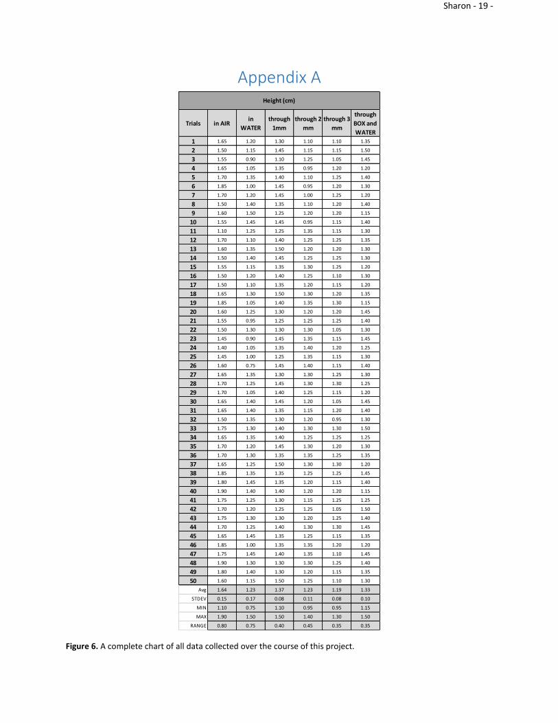
Appendix A
Figure 6. A complete chart of all data collected over the course of this project.
Trials in AIRin
WATER
through
1mm
through 2
mm
through 3
mm
through
BOX and
WATER
1 1.65 1.20 1.30 1.10 1.10 1.35
2 1.50 1.15 1.45 1.15 1.15 1.50
3 1.55 0.90 1.10 1.25 1.05 1.45
4 1.65 1.05 1.35 0.95 1.20 1.20
5 1.70 1.35 1.40 1.10 1.25 1.40
6 1.85 1.00 1.45 0.95 1.20 1.30
7 1.70 1.20 1.45 1.00 1.25 1.20
8 1.50 1.40 1.35 1.10 1.20 1.40
9 1.60 1.50 1.25 1.20 1.20 1.15
10 1.55 1.45 1.45 0.95 1.15 1.40
11 1.10 1.25 1.25 1.35 1.15 1.30
12 1.70 1.10 1.40 1.25 1.25 1.35
13 1.60 1.35 1.50 1.20 1.20 1.30
14 1.50 1.40 1.45 1.25 1.25 1.30
15 1.55 1.15 1.35 1.30 1.25 1.20
16 1.50 1.20 1.40 1.25 1.10 1.30
17 1.50 1.10 1.35 1.20 1.15 1.20
18 1.65 1.30 1.50 1.30 1.20 1.35
19 1.85 1.05 1.40 1.35 1.30 1.15
20 1.60 1.25 1.30 1.20 1.20 1.45
21 1.55 0.95 1.25 1.25 1.25 1.40
22 1.50 1.30 1.30 1.30 1.05 1.30
23 1.45 0.90 1.45 1.35 1.15 1.45
24 1.40 1.05 1.35 1.40 1.20 1.25
25 1.45 1.00 1.25 1.35 1.15 1.30
26 1.60 0.75 1.45 1.40 1.15 1.40
27 1.65 1.35 1.30 1.30 1.25 1.30
28 1.70 1.25 1.45 1.30 1.30 1.25
29 1.70 1.05 1.40 1.25 1.15 1.20
30 1.65 1.40 1.45 1.20 1.05 1.45
31 1.65 1.40 1.35 1.15 1.20 1.40
32 1.50 1.35 1.30 1.20 0.95 1.30
33 1.75 1.30 1.40 1.30 1.30 1.50
34 1.65 1.35 1.40 1.25 1.25 1.25
35 1.70 1.20 1.45 1.30 1.20 1.30
36 1.70 1.30 1.35 1.35 1.25 1.35
37 1.65 1.25 1.50 1.30 1.30 1.20
38 1.85 1.35 1.35 1.25 1.25 1.45
39 1.80 1.45 1.35 1.20 1.15 1.40
40 1.90 1.40 1.40 1.20 1.20 1.15
41 1.75 1.25 1.30 1.15 1.25 1.25
42 1.70 1.20 1.25 1.25 1.05 1.50
43 1.75 1.30 1.30 1.20 1.25 1.40
44 1.70 1.25 1.40 1.30 1.30 1.45
45 1.65 1.45 1.35 1.25 1.15 1.35
46 1.85 1.00 1.35 1.35 1.20 1.20
47 1.75 1.45 1.40 1.35 1.10 1.45
48 1.90 1.30 1.30 1.30 1.25 1.40
49 1.80 1.40 1.30 1.20 1.15 1.35
50 1.60 1.15 1.50 1.25 1.10 1.30
Avg 1.64 1.23 1.37 1.23 1.19 1.33
STDEV 0.15 0.17 0.08 0.11 0.08 0.10
MIN 1.10 0.75 1.10 0.95 0.95 1.15
MAX 1.90 1.50 1.50 1.40 1.30 1.50
RANGE 0.80 0.75 0.40 0.45 0.35 0.35
Height (cm)

Sharon - 20 -
Appendix B
Arduino Code with LED Modifications /** * ---------------------------------------------- * MFRC522 Arduino * Reader/PCD Uno/101 * Signal Pin Pin * ---------------------------------------------- * RST/Reset RST 9 * SPI SS SDA(SS) 10 * SPI MOSI MOSI 11 / ICSP-4 * SPI MISO MISO 12 / ICSP-1 * SPI SCK SCK 13 / ICSP-3 * */ #include <SPI.h> #include <MFRC522.h> #define RST_PIN 9 // Configurable, see typical pin layout above #define SS_PIN 10 // Configurable, see typical pin layout above MFRC522 mfrc522(SS_PIN, RST_PIN); // Create MFRC522 instance. MFRC522::MIFARE_Key key; /** * Initialize. */ int blue = 5; int red = 3; int green = 6; void setup() { pinMode(blue, OUTPUT); pinMode(red, OUTPUT); pinMode(green, OUTPUT); Serial.begin(9600); // Initialize serial communications with the PC while (!Serial); // Do nothing if no serial port is opened SPI.begin(); // Init SPI bus mfrc522.PCD_Init(); // Init MFRC522 card // Prepare the key (used both as key A and as key B) // using FFFFFFFFFFFFh which is the default at chip delivery from the factory for (byte i = 0; i < 6; i++) { key.keyByte[i] = 0xFF; } //Serial.println(F("Scan a MIFARE Classic PICC to demonstrate read and write.")); //Serial.print(F("Using key (for A and B):")); dump_byte_array(key.keyByte, MFRC522::MF_KEY_SIZE); //Serial.println(); //Serial.println(F("BEWARE: Data will be written to the PICC, in sector #1")); } /** * Main loop. */ void loop() { digitalWrite(red, LOW); digitalWrite(blue, LOW); digitalWrite(green, LOW); // Look for new cards

Sharon - 21 -
if ( ! mfrc522.PICC_IsNewCardPresent()) return; // Select one of the cards if ( ! mfrc522.PICC_ReadCardSerial()) return; // Show some details of the PICC (that is: the tag/card) //Serial.print(F("Card UID:")); digitalWrite(blue, HIGH); dump_byte_array(mfrc522.uid.uidByte, mfrc522.uid.size); //Serial.println(); //Serial.print(F("PICC type: ")); MFRC522::PICC_Type piccType = mfrc522.PICC_GetType(mfrc522.uid.sak); //Serial.println(mfrc522.PICC_GetTypeName(piccType)); // Check for compatibility if ( piccType != MFRC522::PICC_TYPE_MIFARE_MINI && piccType != MFRC522::PICC_TYPE_MIFARE_1K && piccType != MFRC522::PICC_TYPE_MIFARE_4K) { //Serial.println(F("This sample only works with MIFARE Classic cards.")); return; } // sector #1, covering block #4 up to and including block #7 byte sector = 1; byte blockAddr = 4; byte dataBlock[] = { 0x01, 0x02, 0x03, 0x04, // 1, 2, 3, 4, 0x05, 0x06, 0x07, 0x08, // 5, 6, 7, 8, 0x08, 0x09, 0xff, 0x0b, // 9, 10, 255, 12, 0x0c, 0x0d, 0x0e, 0x0f // 13, 14, 15, 16 }; byte trailerBlock = 7; MFRC522::StatusCode status; byte buffer[18]; byte size = sizeof(buffer); // Authenticate using key A //Serial.println(F("Authenticating using key A...")); status = (MFRC522::StatusCode) mfrc522.PCD_Authenticate(MFRC522::PICC_CMD_MF_AUTH_KEY_A, trailerBlock, &key, &(mfrc522.uid)); if (status != MFRC522::STATUS_OK) { digitalWrite(blue, LOW); digitalWrite(red, HIGH); delay(1000); // Serial.print(F("PCD_Authenticate() failed: ")); // Serial.println(mfrc522.GetStatusCodeName(status)); return; } // Show the whole sector as it currently is //Serial.println(F("Current data in sector:")); mfrc522.PICC_DumpMifareClassicSectorToSerial(&(mfrc522.uid), &key, sector); //Serial.println(); // Read data from the block //Serial.print(F("Reading data from block ")); Serial.print(blockAddr); //Serial.println(F(" ...")); status = (MFRC522::StatusCode) mfrc522.MIFARE_Read(blockAddr, buffer, &size); if (status != MFRC522::STATUS_OK) { digitalWrite(blue, LOW); digitalWrite(red, HIGH); delay(1000); //Serial.print(F("MIFARE_Read() failed: ")); //Serial.println(mfrc522.GetStatusCodeName(status)); } //Serial.print(F("Data in block ")); Serial.print(blockAddr); Serial.println(F(":")); dump_byte_array(buffer, 16); //Serial.println();
Sharon - 22 -
//Serial.println(); // Authenticate using key B //Serial.println(F("Authenticating again using key B...")); status = (MFRC522::StatusCode) mfrc522.PCD_Authenticate(MFRC522::PICC_CMD_MF_AUTH_KEY_B, trailerBlock, &key, &(mfrc522.uid)); if (status != MFRC522::STATUS_OK) { digitalWrite(blue, LOW); digitalWrite(red, HIGH); delay(1000); //Serial.print(F("PCD_Authenticate() failed: ")); //Serial.println(mfrc522.GetStatusCodeName(status)); return; } // Write data to the block //Serial.print(F("Writing data into block ")); Serial.print(blockAddr); //Serial.println(F(" ...")); dump_byte_array(dataBlock, 16); Serial.println(); status = (MFRC522::StatusCode) mfrc522.MIFARE_Write(blockAddr, dataBlock, 16); if (status != MFRC522::STATUS_OK) { digitalWrite(blue, LOW); digitalWrite(red, HIGH); delay(1000); //Serial.print(F("MIFARE_Write() failed: ")); //Serial.println(mfrc522.GetStatusCodeName(status)); } //Serial.println(); // Read data from the block (again, should now be what has been written) //Serial.print(F("Reading data from block ")); Serial.print(blockAddr); //Serial.println(F(" ...")); status = (MFRC522::StatusCode) mfrc522.MIFARE_Read(blockAddr, buffer, &size); if (status != MFRC522::STATUS_OK) { digitalWrite(blue, LOW); digitalWrite(red, HIGH); delay(1000); //Serial.print(F("MIFARE_Read() failed: ")); //Serial.println(mfrc522.GetStatusCodeName(status)); } // Serial.print(F("Data in block ")); Serial.print(blockAddr); Serial.println(F(":")); dump_byte_array(buffer, 16); //Serial.println(); // Check that data in block is what we have written // by counting the number of bytes that are equal // Serial.println(F("Checking result...")); byte count = 0; for (byte i = 0; i < 16; i++) { // Compare buffer (= what we've read) with dataBlock (= what we've written) if (buffer[i] == dataBlock[i]) count++; } // Serial.print(F("Number of bytes that match = ")); Serial.println(count); if (count == 16) { digitalWrite(green, HIGH); delay(1000); // Serial.println(F("Success :-)")); } else { digitalWrite(red, HIGH); delay(1000); // Serial.println(F("Failure, no match :-(")); } // Serial.println(); // Dump the sector data // Serial.println(F("Current data in sector:")); mfrc522.PICC_DumpMifareClassicSectorToSerial(&(mfrc522.uid), &key, sector); // Serial.println();

Sharon - 23 -
// Halt PICC mfrc522.PICC_HaltA(); // Stop encryption on PCD mfrc522.PCD_StopCrypto1(); digitalWrite(red, LOW); digitalWrite(green, LOW); digitalWrite(blue, LOW); } void dump_byte_array(byte *buffer, byte bufferSize) { for (byte i = 0; i < bufferSize; i++) { // Serial.print(buffer[i] < 0x10 ? " 0" : " "); // Serial.print(buffer[i], HEX); } }

Sharon - 24 -
Appendix C
Limitations and Assumptions
The only pair of goggles that were available for testing during the course of the project
were Speedo goggles. Therefore, it is assumed that any person who uses the device will also
use the same make of goggles. Otherwise, the piece that connects the fob tag to the goggles
will not fit. The code written to run the RFID was assumed to be correct, and the RFID was
assumed to work as stated in the product description when the module was purchased.
Sharon - 25 -
Appendix D
Background Notes A pair of swimming goggles that have a proximity sensor attached to warn the swimmer of the
approaching wall.
DAYA SHARON
LAST UPDATED: FEBRUARY 13, 2017
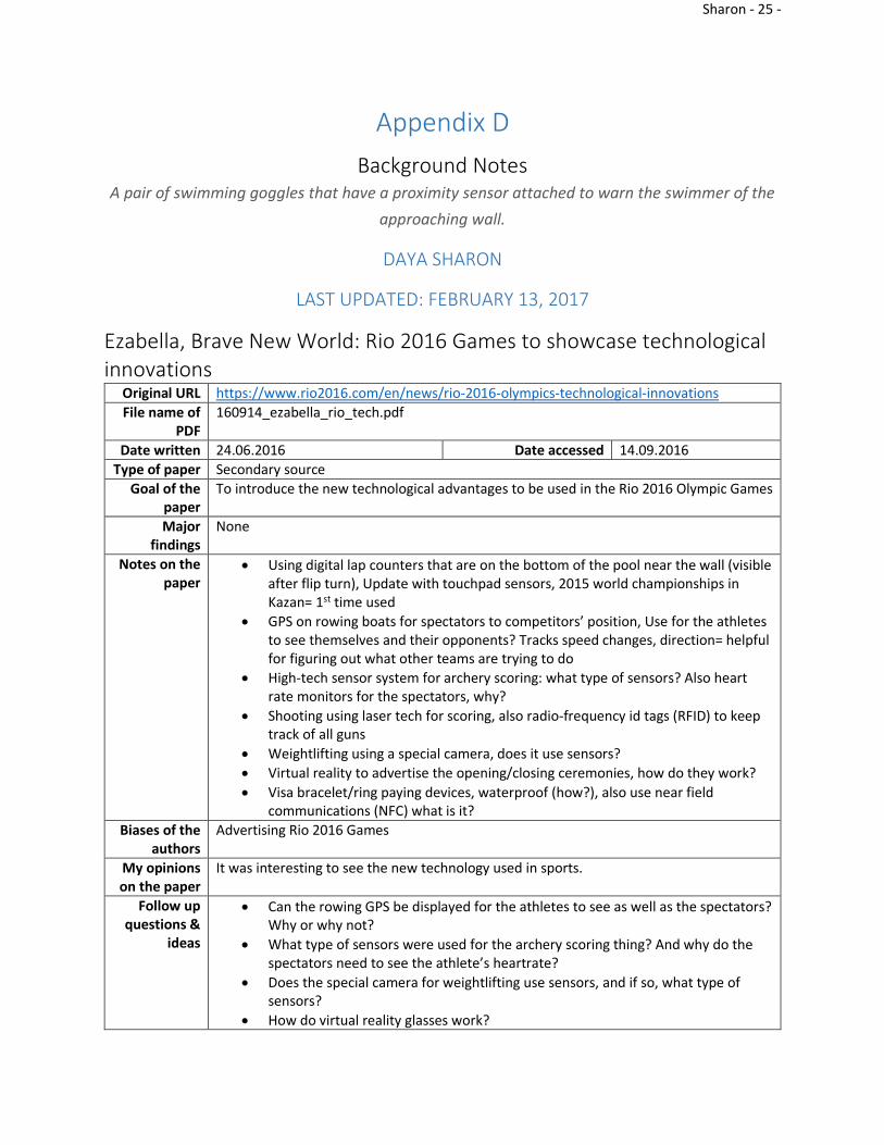
Ezabella, Brave New World: Rio 2016 Games to showcase technological innovations
Original URL https://www.rio2016.com/en/news/rio-2016-olympics-technological-innovations
File name of PDF
160914_ezabella_rio_tech.pdf
Date written 24.06.2016 Date accessed 14.09.2016
Type of paper Secondary source
Goal of the paper
To introduce the new technological advantages to be used in the Rio 2016 Olympic Games
Major findings
None
Notes on the paper
Using digital lap counters that are on the bottom of the pool near the wall (visible after flip turn), Update with touchpad sensors, 2015 world championships in Kazan= 1st time used
GPS on rowing boats for spectators to competitors’ position, Use for the athletes to see themselves and their opponents? Tracks speed changes, direction= helpful for figuring out what other teams are trying to do
High-tech sensor system for archery scoring: what type of sensors? Also heart rate monitors for the spectators, why?
Shooting using laser tech for scoring, also radio-frequency id tags (RFID) to keep track of all guns
Weightlifting using a special camera, does it use sensors?
Virtual reality to advertise the opening/closing ceremonies, how do they work?
Visa bracelet/ring paying devices, waterproof (how?), also use near field communications (NFC) what is it?
Biases of the authors
Advertising Rio 2016 Games
My opinions on the paper
It was interesting to see the new technology used in sports.
Follow up questions &
ideas
Can the rowing GPS be displayed for the athletes to see as well as the spectators? Why or why not?
What type of sensors were used for the archery scoring thing? And why do the spectators need to see the athlete’s heartrate?
Does the special camera for weightlifting use sensors, and if so, what type of sensors?
How do virtual reality glasses work?
Sharon - 26 -
What makes the Visa ring waterproof? And what is NFC?
keywords Rio, Olympics, Technology, digital lap counters, innovations
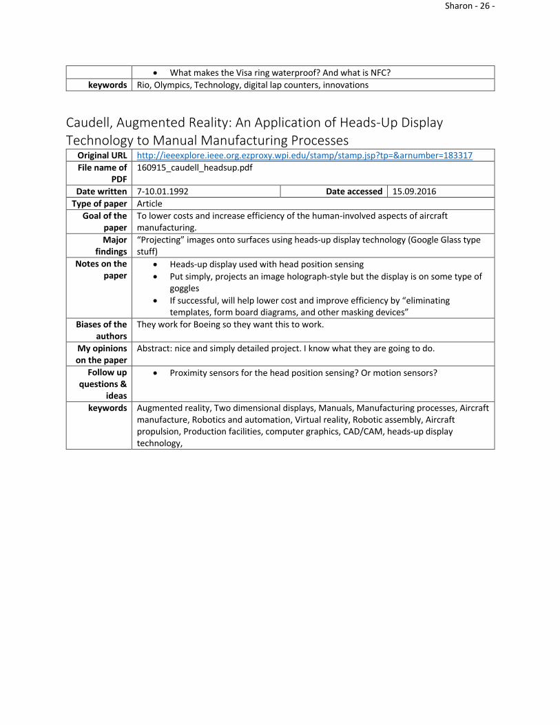
Caudell, Augmented Reality: An Application of Heads-Up Display Technology to Manual Manufacturing Processes
Original URL http://ieeexplore.ieee.org.ezproxy.wpi.edu/stamp/stamp.jsp?tp=&arnumber=183317
File name of PDF
160915_caudell_headsup.pdf
Date written 7-10.01.1992 Date accessed 15.09.2016
Type of paper Article
Goal of the paper
To lower costs and increase efficiency of the human-involved aspects of aircraft manufacturing.
Major findings
“Projecting” images onto surfaces using heads-up display technology (Google Glass type stuff)
Notes on the paper
Heads-up display used with head position sensing
Put simply, projects an image holograph-style but the display is on some type of goggles
If successful, will help lower cost and improve efficiency by “eliminating templates, form board diagrams, and other masking devices”
Biases of the authors
They work for Boeing so they want this to work.
My opinions on the paper
Abstract: nice and simply detailed project. I know what they are going to do.
Follow up questions &
ideas
Proximity sensors for the head position sensing? Or motion sensors?
keywords Augmented reality, Two dimensional displays, Manuals, Manufacturing processes, Aircraft manufacture, Robotics and automation, Virtual reality, Robotic assembly, Aircraft propulsion, Production facilities, computer graphics, CAD/CAM, heads-up display technology,

Sharon - 27 -
Hagem, Self-Contained Adaptable Optical Wireless Communications System for Stroke Rate During Swimming
Original URL http://ieeexplore.ieee.org.ezproxy.wpi.edu/xpls/icp.jsp?arnumber=6515615#article
File name of PDF
160925_hagem_wireless.pdf
Date written July 10, 2013 Date accessed 25.09.2016
Type of paper Journal Article
Goal of the paper
To introduce a system that measures a swimmer’s stroke rate and stroke length in order to display the swimmer’s velocity in his/her goggles.
Major findings
Created the system described above.
Notes on the paper
Used LEDs to indicate faster/slower/good pace to swimmers- I wanted to do that
Measured stroke rate from top to top and compared stroke rate for speed analysis
Real-time info is important for swimmers for training
Wireless communications: a) radio frequency is not good because water disrupts the waves b) acoustic communication is not fun for the swimmers, it’s scary to hear someone talk to you when they shouldn’t be able to/loud noises c) light waves are still messed up by the water but not as badly
Biases of the authors
They want it to work.
My opinions on the paper
I thought they worked backwards. They explained their own design last, which left me with a lot of questions that weren’t answered until later.
Follow up questions &
ideas
They mentioned injury recovery/prevention. Is there any way my project could help with that?
Wireless communication techniques?
How did they do that thing with the RGB LEDs without coach input?
keywords Underwater optical wireless communication, accelerometer, real time swimmers feedback, stroke rate, visible light communication

Sharon - 28 -
Hagem, Coach-Swimmer communications based on wrist mounted 2.4 GHz accelerometer sensor
Original URL http://ac.els-cdn.com.ezproxy.wpi.edu/S1877705815014915/1-s2.0-S1877705815014915-main.pdf?_tid=513ba2e6-8365-11e6-81a6-00000aab0f6b&acdnat=1474838365_ce6c534fb451a143a715d49feefbab08
File name of PDF
160925_hagem_coach.pdf
Date written January 1, 2015 Date accessed 25.09.2016
Type of paper Journal Article
Goal of the paper
To introduce this system of coach to swimmer communication about stroke rate
Major findings
Creating the system described above
Notes on the paper
Instant feedback from coach to swimmer
Measures stroke rate, stroke length, and velocity (same as the above article)
Radio frequencies still fail because the water still disrupts the waves
Sound feedback is still bad because no one can hear anything while they swim
Biases of the authors
They want this to be a success
My opinions on the paper
I was a little disappointed that they never mentioned the swimmer’s display system. Is there even one? I thought it just repeated most of the same things as the article above, which is, coincidentally, written by the same authors.
Follow up questions &
ideas
They never describe the display system that the swimmer sees
keywords Body sensor networks; real-time communication; gesture identification; acceleration measurements; swimming.

Sharon - 29 -
Taba, Electronic Timing Swimmer’s Goggles Original URL https://patents.google.com/patent/US5685722A/en?q=swimming+goggles&q=proximity+
sensors
File name of PDF
161003_taba_electronicTiming.pdf
Date written 11.11.1997 Date accessed 10.3.2016
Type of paper Patent
Goal of the paper
To introduce a pair of swimming goggles with electronic timing and a display
Major findings
Created technology described
Notes on the paper
used a lot of other patents
one of these patents describes a “submersible” device for non-contact timers
the device has an accelerometer that detect strokes and times them. it’s able to distinguish flip turns as well
the accelerometer can also detect stops (end of race)
the device then displays the total time for the race and the last split time
also displays heart rate with flashing lights for increasing/decreasing
magnetic switches and wipers to count laps
has removable batteries
liquid crystal displays
for pulse monitor, has an LED or other light display
Biases of the authors
They want this product to succeed.
My opinions on the paper
It was very in depth. The wording was a little vague, which was odd, but I understood enough of it.
Follow up questions &
ideas
Patents to look up: 5162828, 4757714, 5136621, 4776045, 4796987, 5258785
how does the accelerometer help?
sound vs light underwater
keywords goggles, liquid crystal displays, accelerometer

Sharon - 30 -
Yokota, Swimming Goggles Origina
l URL https://patents.google.com/patent/US7165837B2/en?q=swimming+goggles&q=proximity+sensors&q=A63B33%2f002
File name
of PDF
161003_yokota_goggles.pdf
Date written
1.23.2007 Date accessed 10.5.2016
Type of paper
Patent
Goal of the
paper
To make swimming goggles that make it easier to avoid light refraction and improve the field of vision
Major finding
s
Created technology described.
Notes on the paper
not enough space in front of eyes = blurry vision
all the angles on this product are very specialized to make sure that there is no light refraction or any other issues with vision
nose bridge made of polyurethane plastic
goggle strap made of stretchy, rubbery elastic material
goggles made of transparent plastic (cellulosic plastic, acrylic plastic, polycarbonate, etc.)
suction cushion on eyepieces is removable (my goggles vs dad’s)
optimizing field of vision by making the slant of the eyepiece offset from the direct line of sight
Biases of the
authors
They want the product to be successful.
My opinion
s on the
paper
I thought it was very interesting and descriptive. It wasn’t hard to understand, just a little repetitive.
Follow up
questions &
ideas
how did they get the information about line of sight? -> surveys or experiments?
they keep mentioning graphics and colors and text and other visual display items to put in the difficult-viewing section of the goggles but they never mention what it’d be used for
keywords
swimming goggles, line of sight

Sharon - 31 -
Hazell, Spectacles with embedded segmented display comprising light guide end
Original URL
https://patents.go.com/patent/US2008v0316605A1/en?q=swimming+goggles&q=proximity+sensors&q=A63B33%2f002
File name
of PDF
161003_hazell_spectacles.pdf
Date written
12.25.2008 Date accessed 10.9.2016
Type of paper
Patent
Goal of the
paper
To introduce an inexpensive optical device that has a display built into the device
Major finding
s
Created technology described
Notes on the paper
3 types of display: see-through, see around (slight obstruction to field of vision), and fully-blocking
use ‘optical guides’ to guide light into a segmented display
does not obstruct the wearer’s field of vision
references a “transparent substrate”, which is just the lens of the optical device (the clear part that you see through)
the display is focused at infinity allowing the user to see through the display and still be able to read the display
uses an angle to reflect the light at the end of the optical guide
displays can be numbers or letters and numbers, using 7, 14, or 16 segments
easily waterproofable
can be applied to cameras, car windshields, etc.
for swimming, can display time, distance traveled (lap count), heart-rate (they’re just spouting out ideas now)
can be used on normal correcting glasses as well
the characters in the display can be anywhere from 0.1 to 1 mm in height, though they are usually 0.5 mm
LEDs can/are used as the light source
Optical guides end in a way that it shows one segment/pixel of the display
Biases of the
authors
They want the product to be successful.
My opinion
s on the
paper
The paper was easy enough to understand once I found the first descriptions they used. They described things at the very beginning and it was very easy to miss. But then the rest of the patent didn’t make sense so I had to go back and reread.
Follow up
questio
look up patent 5,886,822
refractive optics?
How do you focus displays at infinity? Just how does that work and what does it mean?

Sharon - 32 -
ns & ideas
keywords
LED, display, spectacles
Chen, Design and Implementation of capacitive proximity sensor using microelectromechanical systems technology
Original
URL
http://libraries.state.ma.us/login?gwurl=http://go.galegroup.com/ps/i.do?p=AONE&sw=w&u=mlin_c_worpoly&v=2.1&id=GALE%7CA57877561&it=r&asid=3a0d6c0a5c7a823b82718656bb09f416
File name of PDF
161005_chen_capacitiveProximity.pdf
Date written
12.1998 Date accessed 10.05.2016
Type of
paper
Journal article
Goal of
the pap
er
To introduce a proximity sensor that uses microelectromechanical systems technology
Major
findings
Created and tested technology described
Notes on
the pap
er
Very small sensors, but size is flexible
Use “smart sensors”
Apparently 4/5 measurements in industry are displacement measurements
Two types of capacitive sensors: 1. Parallel-plate capacitor 2. Fringe capacitor
Parallel-plate: sensor is one plate and object is the other, object must a conductor for sensor to sense it, useless when object in rotating or is coated in something
Fringe: electrodes, metal screens, and other stuff I don’t understand
Biases of
the auth
ors
They want their idea to be used and to be successful.
My opinions
The article gave me a good basic overview of the two types of capacitive sensors. The science behind it is a little too complicated for me, however, which made it very hard to understand the article.

Sharon - 33 -
on the pap
er
Follow up
questions &
ideas
What are “smart sensors”?
keywor
ds
fringe capacitance, microelectromechanical systems, proximity sensor
Nath, RFID Technology and Applications Original URL http://ieeexplore.ieee.org.ezproxy.wpi.edu/document/1593567/?reload=true
File name of PDF
161009_nath_rfid.pdf
Date written January 2006 Date accessed 10.09.2016
Type of paper Journal Article
Goal of the paper
To explain the technology and applications of RFIDs
Major findings
The applications of RFIDs
Notes on the paper
Battery-less tags read by a reader
“EZ-Pass”
Static readers: don’t move: for car rentals?
Luggage labels also?
Mobile readers: put it in our phones to use as price scanners?
Biases of the authors
None
My opinions on the paper
It was quite literally just applications, which was kind of annoying because I wanted how the technology works.
Follow up questions &
ideas
“An Introduction to RFID Technology” by Roy Want
keywords RFID, applications, technology

Sharon - 34 -
Schill, Visible Spectrum Optical Communication and Distance Sensing for Underwater Applications
Original URL n/a
File name of PDF
161025_schill_underwater.pdf
Date written 2004 Date accessed 10.25.2016
Type of paper conference proceedings
Goal of the paper
To introduce an optical communication system for underwater applications
Major findings
Tested the system described above
Notes on the paper
Used LEDs to measure the efficiency of an optical communications system
Low bandwidth for data, but still sufficient enough for this purpose
Compromise speed for range
They want: a communication range of more than one meter, multidirectional coverage, small size, and low cost-------- it’s their design matrix
Longer ranged devices are too big for their application: swarm robot communication
Different wavelengths of visible light are absorbed at different rates
Two parts: transmitter and receiver
Prototype costs: AUS$ 45 each or $34.59 USD each
Distance sensing is done by using time received and kinematics
Biases of the authors
They want their system to work.
My opinions on the paper
I thought the paper was easy enough to read, but the authors used a lot of jargon that I didn’t know.
Follow up questions &
ideas
How fast is the data relayed to the display?
Is this all instantaneous?
keywords distance sensing, optical communication, underwater technology

Sharon - 35 -
Schill, Personal Communication Original URL n/a
File name of PDF
Date recieved Date accessed
Type of paper email
Goal of the paper
response to my email
Major findings
Notes on the paper
Hi,
Thank you for your interest :) The output is pretty much instantaneous in terms of data
transmission (6000 bytes/second, so more or less 1/6000 sec latency per transmitted
byte). However, as I understand you are not interested in the data transmission part, but
rather the distance sensing? In my paper, the distance/proximity sensing was a neat
side-effect in a device primarily designed for communication. The method indirectly
measures the signal strength by looking at the number of received bytes as a proxy for
the bit error rate. This only works in a small range where the signal strength is at the
edge of the range - if the signal is too strong, no bytes are lost, so the only distance
information you'd get is "it's close", but not how far away. Also, to get the error
statistics, one needs to integrate over a number of bytes, which increases the delay -
but looking at 100 bytes would still give you 1/60 sec latency which is still pretty fast.
The size of the device back then wasn't optimized, but I'm currently working on a
similar optical modem for my company Hydromea( http://hydromea.com ) which is
30x50mm, with 9 LEDs. It could be made a bit smaller with less LEDs. There is other
work by some colleagues done in air, specifically for distance sensing using similar
methods. In this case they directly measure the received signal strength of the optical
pulses, instead of the detour through an IrDA decoder chip, as they didn't need to
communicate through the device.
Here are some references:
https://infoscience.epfl.ch/record/131138/files/IEEE-ASME-TMech09_camera-
ready.pdf
https://infoscience.epfl.ch/record/139026/files/RobertsIROS2009_2.pdf
Maybe also look up James Robert's thesis, it might contain more information.
What you should be aware of however is that in all cases, the light emitter is well-
known and the signal has direct line of sight, while in your case I assume the light is
indirectly reflected off a wall, so the signal strength also depends on the color and
brightness of the wall, reducing the accuracy. As pools are pretty consistent it might
not be a big problem, depending on the accuracy you need.
For precise distance measurements underwater you might also want to look at acoustic
systems (ultrasound). Underwater acoustics is generally tricky, and you probably want
a very small system, but for the relatively short distances in your project it could be
doable. There are some ultrasonic transducers for cars (reverse parking sensors) that
are splash-proof/waterproof, you might be able to use those, and an adapted circuit of
an ultrasonic distance sensor for air, and get some results. Alternatively, you could try
some of the new low-cost Lidar sensors (time of flight with light), e.g. TeraRanger, or
check at Sparkfun electronics. The problem here is that IR light doesn't go through
water terribly well, you'll want blue or green light, but it might be another avenue to
explore.

Sharon - 36 -
Best of luck,
Felix
Biases of the authors
My opinions on the paper
Follow up questions &
ideas
keywords
Schill, Personal Communication Original URL
File name of PDF
Date written 11.7.16 Date accessed 11.7.16
Type of paper Personal Communication
Goal of the paper
Major findings
Notes on the paper
Hi,
Radio communication in water doesn't work terribly well, particularly at high
frequencies. In saltwater, wifi or bluetooth would only have a range of a few
centimeters. In freshwater it might work for very short distances (<1m). I'd
recommend doing a very quick test first to see if it's feasible, before investing
time. Lower frequencies work better, but it's more difficult to find radio
modules sub-Ghz. Underwater can be challenging... :) But if in doubt, just try it
out and see what works :)
All the best,
Felix
Biases of the authors
My opinions on the paper
Follow up questions &
ideas
keywords