Embed Size (px)
Citation preview

S w i f t M o t o r h o m e s
O w n e r ' s H a n d b o o k

Congratulations. You couldn’t
have made a better choice than
a Swift motorhome.
And when it comes to buying
a new motorhome or car, Black
Horse are the finance experts.
With a range of finance options
to suit you, and a wealth of
experience, you can relax in the
knowledge that Swift and
Black Horse are right behind
you wherever you want to go.
Wherever youwant to go,we’reright behind you.
Credit is available to persons aged 18 or over. Guarantors may be required. Written quotations available on request from: Black Horse Caravan Finance, 24 - 26 Newport Road, Cardiff CF24 0SR Tel: 029 2029 6863
Introduction
INTRODUCTIONDEAR OWNER
THANK YOU FOR DECIDING TO BUY ONEOF OUR NEW MOTORHOMES. WE ARESURE YOU WILL ENJOY MANY HAPPYHOURS IN IT AND WE HOPE THEINFORMATION AND HINTS IN THISHANDBOOK WILL HEIGHTEN YOURENJOYMENT.
THE HANDBOOK HAS BEEN DESIGNEDTO GIVE YOU A GENERAL GUIDE TO THECARE, USE AND MAINTENANCE OF YOURMOTORHOME. WHETHER YOU ARE ANEW OR AN EXPERIENCED MOTORHOMEUSER THE HINTS WILL HELP TO PROTECTYOUR INVESTMENT.
THE INFORMATION CONTAINED WILLANSWER MOST OF YOUR QUERIES, BUTIF THERE ARE ANY ASPECTS WHICH ARENOT COVERED PLEASE CONSULT YOURAPPOINTED DEALER.
HAPPY TOURING!
IMPORTANT - PLEASE QUOTE THEBODY BUILD NUMBER & BASE VEHICLECHASSIS NUMBER IN ALLCORRESPONDENCE WITH YOURDEALER OR SWIFT GROUP LIMITED.
All the illustrations and descriptive matter inthis handbook are intended to give a generalidea of the motorhome. Changing marketand supply situations may prevent us frommaintaining the exact specification details inthis handbook, we therefore reserve theright to alter specifications as materials andconditions demand.
Dealers are not agents of Swift GroupLimited and have absolutely no authority tobind Swift Group Limited by any express orimplied undertaking or representation.
CONTENTS
The Motorhome Code...............................................1
Preparing for the Road............................................ 5
‘En Route’ ................................................................. 9
Safety & Security.................................................... 11
Arrival at Site .......................................................... 13
Connecting Services.............................................. 15
Electrical Systems ................................................. 27
Equipment Details.................................................. 43
Motorhome Care .................................................... 83
Useful Information ................................................. 89
Index........................................................................ 94
THEMOTORHOME
CODE
Code of Conduct .............................................................................. 2
The Country Code ............................................................................ 4
The Coastal Code ............................................................................. 4
Motorhome Code
CODE OF CONDUCTCAMP SITES
ArrivalsReport to reception immediately on arrival.
Vehicle MovementKeep to roadways unless otherwise directed.
Adhere to speed limits. Note that these aregenerally 10 mph. (Remember that thestopping distance on grass is considerablygreater than on tarmac.)
Only a person in possession of a currentdriving licence may drive on the site.
Park correctly as advised on your pitch.Where possible leave 20 feet of free spacearound your vehicle.
Use of Site AppliancesUse the electrical mains hook-up in thecorrect manner and with caution.
Ensure that all fresh water taps/connectionsare turned off after use.
Have care and consideration when using allfacilities (toilets and showers etc) and leaveclean and tidy. Young children should besupervised.
Waste DisposalIf the vehicle is not fitted with a waste watertank, a suitable receptacle should be placedbelow all waste water outlet pipes. Do not letthese containers overflow.
Dispose of all waste water where instructed.
Empty effluent from chemical toilets whereinstructed.
To avoid possible damage to sewagepurification works, only approved chemicalfluids must be used. Under nocircumstances should coal tar, phenol orcaustic-based fluids be used.
Disposable napkins and similar bulky itemsmust not be put into chemical closetemptying points but should be wrapped in apolythene bag and placed in the containerprovided.
Place all litter in containers marked for thepurpose.
NoiseDo not make excessive noise.
Children should be restrained from makingexcessive noise.
Flying kites and model aircraft and the use ofitems like catapults or air-guns, as well asball games, should not be permitted among,or close to other vehicles.
Musical instruments, record players, radiosand televisions should not be used to theinconvenience of other people on the site.
Open and close doors quietly.
Power generators must be adequatelysilenced and used with consideration.
Dogs and other PetsAll dogs and other pets should be keptunder control.
Unless permission has been granted, noanimal should be allowed loose on the siteand leads must not exceed 10ft.
No animals should be allowed in theshower/toilet blocks.
Do not let dogs foul the site.
Fire PrecautionsAdhere to and take note of fire precautionsnoting the whereabouts of the fire points.
WARNING: Provide one dry powder fire extinguisher of an approved type or complying with ISO 7165, of at least 1kg capacity, by the main exterior door and a fire blanket next to the cooker. Familiarise yourself with the operating instructions on your fire extinguisher and the local fire precaution arrangements.
2
Motorhome CodeWhen using a dry powder extinguisher it issuggested that the motorhome be evacuateduntil the powder has settled, to avoidinhalation.
Unless permission has been granted,barbecues should not be used. If permissionis given, consideration should be given tothe annoyance that can be caused to otherusers of the site.
Open fires are not allowed.
Awnings and TentsAwnings and tents should only be usedwhen permission has been obtained.
When on grass and staying for more than afew days, the ground sheet and/or side flapsof awnings should be periodically raised inorder to avoid damage to the ground.
DepartureLeave the pitch clean and tidy.
On leaving, check out with reception payingthe required fees.
WILD CAMPING
Camping away from licensed sites, withoutthe permission from the land owner or hisagents, is not allowed in the UnitedKingdom.
When permission has been granted, allaspects of this Code should be adhered to.
On no account should:
(a) Litter be disposed of other than in the receptacles provided.
(b) Water be allowed to escape from the vehicle.
(c) Chemical toilets be emptied except into the disposal places agreed with the land owner.
(d) Washing or similar be hung outside the vehicle.
PARKING
Motorhomes should only be parked inapproved places.
When using the facilities of a motorhomecare and consideration should be given tothose around them.
DRIVING
When using a motorhome on either thepublic highway or private roads the HighwayCode should be complied with and fullconsideration given to other road users.
In the event of a motorhome travelling slowlythe driver of the motorhome should, wherepossible, pull over in order to let other trafficpass.
When the vehicle is in motion it iscompulsory for all front seat passengers towear seat belts and strongly recommendedfor rear seated passengers, where fitted.
Before moving off, elevated roofs should belowered and correctly secured, and tophinged windows closed. Likewise all doorsand access lockers for gas containers andchemical toilets must be properly secured.
Exterior steps should be properly retractedand secured.
When the vehicle is being refuelled, or on aferry, all gas systems must be turned off.
HANDBOOK
Before using a motorhome all aspects of thehandbooks, produced by the chassismanufacturer and the converter, must beread and adhered to.
ENVIRONMENT
Care and consideration should be taken toprotect the environment.
Observe the Country and Coastal Codesshown overleaf.
3
Motorhome Code
THE COUNTRY CODEEnjoy the countryside but respect its life andwork.
More people than ever before are exploringthe countryside, interested in farming, plantlife, bird watching or just observing thegeneral wildlife. Whatever your interest, thereis a lot to learn, but please observe thefollowing code.
1. Guard against all risk of fires. Hay and heathland catch alight easily and once ablaze are very hard to put out.
REMEMBER: FIRE SPREADS QUICKLY.
2. Keep to the public paths across farmland.
3. Use gates and stiles to cross fences, hedges and walls.
4. Leave livestock, crops and machinery alone. View from a distance.
5. Take your litter home - it is unsightly and harmful to wildlife.
6. Help to keep all water clean.
7. Take special care on country roads.
8. Make no unnecessary noise. Most animals are very timid; noises can disturbthem unnecessarily. If you want to get thebest out of the country, go quietly.
THE COASTAL CODEAs our coastlines are increasingly used forrecreation and education, the followingsuggestions are made to enable us to enjoyour inheritance and preserve it for posterity.
Disturbance may mean DEATH.
DO NOT trample about, or move rocksunnecessarily.
DO NOT frighten seals or seabirds.
DO NOT spill detergents, solvents or fuelfrom boats as these can kill marine life.
When sailing, moderate your speed - thewash from a fast boat can destroy banksand nests.
Live molluscs and crustaceans need not becollected as souvenirs - dead shells canusually be found.
Shellfish can take years to grow and finescan be imposed for not observing nationalregulations.
DO NOT pull up seaweeds unnecessarily.
Make your visit instructive - not destructive.
Look at material - don’t remove it. Takenotes and photographs, not specimens.
Observe by-laws and be considerate toothers.
National Trust property and Country Parkshave regulations to protect the wildlife.Follow these and the Country and CoastalCodes.
4
PREPARINGFOR THE
ROAD
Before Moving Off .................................................................... 6
Loading of Vehicle .................................................................... 6
User Payload Allowance .......................................................... 6
Maximum Technically Permissible Laden Mass ................... 6
Roof Loading ............................................................................ 7
Tyres ............................................................................................7
Three Point Seat Belts ...............................................................7
Preparing for the Road
BEFORE MOVING OFFCheck:
- gas cylinders and all gas operated appliances have been isolated, including fridge, water heater, oven and space heater.
- gas cylinders are correctly positioned, secured and turned off.
- loose articles are stowed securely. Do notstow tins, bottles or heavy items in overhead lockers.
- all lockers and cupboard doors are closed and secured.
- all bunks and ladders are secure in theirstorage or place Luton ladder on its sidein front of Luton bedboards.
- all rooflights are closed and secured.
- main table is stored in its transit position.
- fridge is on 12V operation and door lock is set.
- battery selection switch is in the OFF position.
- tyre pressures and wheel nuts.
- rear corner steadies are raised.
- all drain taps are closed.
- exterior roof rack ladder is raised and secured.
- 230V mains input socket flap is securely closed.
- exterior step (where fitted) is retracted/folded in
Special attention must be taken to ensure alltop hinged windows as well as the Lutonwindows are closed when in transit. All unitsshould be fully closed and latched to preventdamage. The motorhome exterior doorshould also be locked.
LOADING OF VEHICLECorrect weight distribution is an importantfactor in ensuring your vehicle is wellbalanced and easy to drive. It is thereforenecessary to load your motorhome carefullymaking sure all heavy articles are evenlydistributed and are preferably placed in thelower lockers or bed boxes.
WARNING: Do not travel with televisionsor microwaves in overhead lockers unless the appliance was supplied fitted to your motorhome by the manufacturer.
Although it is essential to ensure that thetotal weight of your motorhome does notexceed the stipulated Maximum TechnicallyPermissible Laden Mass, (M.T.P.L.M.), it isimportant to remember that the front andrear axles also have individual maximumweights which must not be exceeded.
These weights, together with the M.T.P.L.M.,can be found on the chassis manufacturer,the Swift Group or Al-Ko plates affixed toyour vehicle under the front edge of thebonnet.
WARNING: Isolate all gas appliances before moving off.
USER PAYLOAD ALLOWANCEThe User Payload (the weight of additionalitems such as personal effects, essentialhabitation equipment and optionalequipment, etc.) is calculated by deductingthe Mass in Running Order (manufacturer’sstandard vehicle specification weight) fromthe Maximum Technically Permissible LadenMass (manufacturer’s maximum authorisedweight).
NOTICE:Please ensure you have allowed for themasses of all the items you intend to carry inyour motorhome.
MAXIMUM TECHNICALLYPERMISSIBLE LADEN MASSThis is the maximum legally allowable weightof the vehicle, fully laden, on the road.
See Specification pages for specific modelweights.
6
Preparing for the Road
ROOF LOADINGA maximum load of 200kgs can be evenlydistributed over the roof area. This figureMUST NOT be exceeded.
The roof areas, up to the over cab section,are capable of withstanding an averageperson’s weight (13 stone or 82.5kg).
Note: Do not walk on the over cab section.
Some motorhome roofs can be fitted with aroof rack (optional).
It is permitted to stand inside the roof rackfitted to the roof. The roof section beyondthe rack is not designed for walking on.
Note: When loading the roof rack, make surethe load is spread evenly and do not allowsharp objects to come into contact with theroof surface.
WARNING: When walking on the roof rack, deck type shoes should be worn - not leather soles.
Do not apply excessive load to the rear suspension of your motorhome or allow the vehicle to reverse with the roof rack access ladder in the down position, touching the ground. This may cause excessive strain on the ladder fixing points.
TYRESThe law requires that the tyres and pressuresmust be suitable for the use to which theyare being put. The minimum tread depthmust be 1.6mm throughout a continuousband comprising the centre three-quarters ofthe breadth of the tread and around thecircumference of the tyre.
Please refer to base vehicle manufacturer'shandbook for tyre pressure information. Thismay also be displayed in the driver's dooraperture.
THREE POINT SEAT BELTSThis section refers to the seat belts locatedin the habitation area of your motorhome.
Fastening the seat belt:Insert tongue into buckle; a positive ‘click’indicates correct assembly.
Releasing the seat belt:Press the red release button, the tongue willbe ejected from the buckle.
- The belt is designed for use by one person and must not be put around a child seated on a persons lap.
- It is important to wear the belt on each journey.
- The belt is suitable for restraining most child seats and boosters.
- It is not intended for children under 6 years of age unless used with other approved restraints.
- The belt should at all times be adjusted and used in accordance with the instructions. No excessive slackness should be present.
- Once installed the diagonal should pass across the centre of the shoulder and the buckle should lie just on or below the hip.
- Avoid twisting the webbing during use. Webbing must not be allowed to chafe against sharp edges.
- Do not make alterations or additions to the belt.
- Belts that have been cut, frayed, damaged or stressed through impact should be replaced. After impact the motorhome anchorage points should alsobe checked.
- To clean use warm soapy water only.
- Periodic inspection of the installation will ensure reliability of the seat belt.
7
'EN ROUTE' Spare Wheel Removal ............................................................ 10
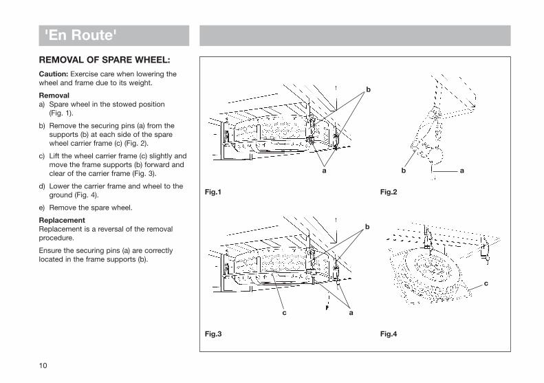
Fig.1
Fig.3
Fig.2
b
a b
Fig.4
'En Route'
REMOVAL OF SPARE WHEEL:Caution: Exercise care when lowering thewheel and frame due to its weight.
Removala) Spare wheel in the stowed position
(Fig. 1).
b) Remove the securing pins (a) from the supports (b) at each side of the spare wheel carrier frame (c) (Fig. 2).
c) Lift the wheel carrier frame (c) slightly and move the frame supports (b) forward and clear of the carrier frame (Fig. 3).
d) Lower the carrier frame and wheel to the ground (Fig. 4).
e) Remove the spare wheel.
ReplacementReplacement is a reversal of the removalprocedure.
Ensure the securing pins (a) are correctlylocated in the frame supports (b).
10
b
a
a
c
c
SAFETY & SECURITY
In Case of Fire ........................................................................ 12
Ventilation ............................................................................... 12
Security ................................................................................... 12
Safety & SecurityIMPORTANT: Your attention is drawn tothe notice affixed in your motorhomeadvising you on fire prevention, ventilationand what to do in case of a fire.
FIREIn case of fire1. Get everyone out of the motorhome as
quickly as possible using whichever exit is quickest including windows. Do not stop to collect any personal items.
2. Raise the alarm. Call the Fire Brigade.
3. Turn off gas supply valve, if safe to do so.
Fire Extinguishers It is recommended that a 1kg (2lb) minimumcapacity dry powder fire extinguishercomplying with the requirements of ISO 7165be carried inside your motorhome at alltimes and a fire blanket be kept next to thecooker.
A fat pan fire should not have anextinguisher aimed at it but be smotheredwith a fire blanket.
ChildrenDo not leave children alone in themotorhome in any event. Keep potentiallydangerous items out of reach as at home,e.g. matches, drugs, etc.
Escape PathsIt is important that you do not block escapepaths to emergency exits with obstructionsor hazards.
VENTILATIONAll motorhomes are built to EN 721. Theventilation points on your motorhome arefixed points of ventilation which are statedby this standard. Under no circumstancesmust these vents be blocked or obstructed.
All ventilation levels are calculated to suiteach models requirements. There should beno modifications made which may result inreduced ventilation levels.
Ventilation is provided at low level by ventsfitted either to the furniture or in the entrancestep, and at high level by the roof lights.
It is advised that fixed ventilation points arechecked and cleaned (if necessary) on aregular basis with a small brush or a vacuumcleaner.
WARNING: NEVER use portable cooking or heating equipment other than electricheaters that are not of the direct radiant type, as it is a fire and asphyxiation hazard.
NEVER allow modification of electrical orLPG systems and appliances except byqualified tradesmen at a Swift Group Dealer
In the interests of safety, replacement partsfor an appliance should conform to theappliance manufacturer's specification andshould be fitted by them or their authorisedagent.
Additional night time ventilation is obtained
on some windows by releasing the windowcatches and placing them in the secondgroove. Note the windows are not sealedfrom rain in this position.
WARNING: Do not obstruct ventilation
SECURITYMotorhome TheftThe theft of a motorhome can occur in themost unlikely circumstances; from a motor-way service area or even an owner’sdriveway.
Secure all windows and doors when yourmotorhome is unoccupied even if only for ashort length of time.
Chassis numberRecord your motorhome chassis number,which can be found under the bonnet, andthe body conversion serial number.
Make a note of these numbers in the spaceprovided at the rear of this handbook andmake a separate note of the numbers tokeep safe at home.
Additional securityWindow etching of the chassis number is acost effective deterrent.
Free crime prevention advice about securingyour motorhome, protecting your valuables,property marking either at home or whilst onsite, can be obtained from the CrimePrevention Officer through your local Policestation.
12
ARRIVAL AT SITE Positioning the Motorhome .................................................. 14
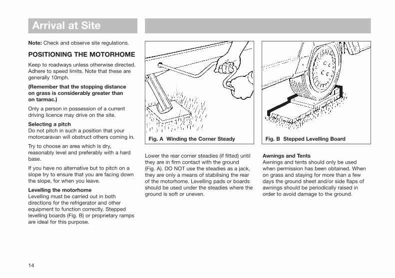
Fig. A Winding the Corner Steady Fig. B Stepped Levelling Board
Arrival at SiteNote: Check and observe site regulations.
POSITIONING THE MOTORHOMEKeep to roadways unless otherwise directed.Adhere to speed limits. Note that these aregenerally 10mph.
(Remember that the stopping distance on grass is considerably greater than on tarmac.)
Only a person in possession of a currentdriving licence may drive on the site.
Selecting a pitchDo not pitch in such a position that yourmotorcaravan will obstruct others coming in.
Try to choose an area which is dry,reasonably level and preferably with a hardbase.
If you have no alternative but to pitch on aslope try to ensure that you are facing downthe slope, for when you leave.
Levelling the motorhomeLevelling must be carried out in bothdirections for the refrigerator and otherequipment to function correctly. Steppedlevelling boards (Fig. B) or proprietary rampsare ideal for this purpose.
Lower the rear corner steadies (if fitted) untilthey are in firm contact with the ground (Fig. A). DO NOT use the steadies as a jack,they are only a means of stabilising the rearof the motorhome. Levelling pads or boardsshould be used under the steadies where theground is soft or uneven.
Awnings and TentsAwnings and tents should only be usedwhen permission has been obtained. Whenon grass and staying for more than a fewdays the ground sheet and/or side flaps ofawnings should be periodically raised inorder to avoid damage to the ground.
14
CONNECTINGSERVICES
Mains Socket/Water Connection .......................................... 16
Water System ......................................................................... 16
Guidance on Cleaning ......................................................... 18
Gas ........................................................................................... 19
Types of Gas ........................................................................ 20
Safety Advice ....................................................................... 21
Electricity ................................................................................ 22
Overseas Connection ............................................................ 23
Wiring Diagram ....................................................................... 24
230V Mains Electrical Equipment Consumption ................. 25
Thermal Insulation and Heating ............................................ 25
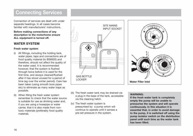
Connecting ServicesConnection of services are dealt with underseparate headings. In all cases becomefamiliar with manufacturers’ instructions.
Before making connections of anydescription to the motorhome ensure ALL equipment is turned off.
WATER SYSTEMFresh water system
(i) All fittings, including the holding tank, water pipes, taps and connections are of food quality material (to BS6920) and therefore, should not affect the quality of the water used. It is recommended however, that the system is flushed through twice before it is used for the first time, and always cleaned/flushed after it has stood unused for a period of time (eg over the winter period). Care hasbeen taken (using smooth bore pipes etc) to eliminate as many water traps as possible.
(ii) When filling the fresh water system remember to check that the water sourceis suitable for use as drinking water and, if you are using a hosepipe or water carrier, that it is also made from non-toxic materials (preferably food quality material).
16
Water Filler Inlet
SITE MAINSINPUT SOCKET
GAS BOTTLELOCKER
(iii) The fresh water tank may be drained via a plug in the base of the tank, accessiblevia the cleaning hatch.
(iv) The fresh water system is pressurised by a pump which willcontinue to operate until it senses a pre-set pressure in the system.
WARNING:If the fresh water tank is completely empty the pump will be unable to pressurise the system and will operate continuously. In this situation it is essential that, in order to avoid damage to the pump, it is switched off using the pump isolator switch on the distribution panel until such time as the water tank has been filled.
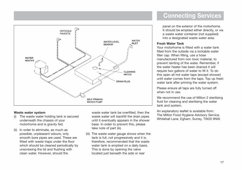
Connecting Servicespanel on the exterior of the motorhome. It should be emptied either directly, or viaa waste water container (not supplied) into a designated waste water area.
Fresh Water TankYour motorhome is fitted with a water tankfilled from the outside via a lockable waterfiller cap. When filling, use a hosemanufactured from non toxic material, toprevent tainting of the water. Remember, ifthe water heater has been drained it willrequire two gallons of water to fill it. To dothis open all hot water taps (except shower)until water comes from the taps. Top up freshwater tank after priming the water system.
Please ensure all taps are fully turned offwhen not in use.
We recommend the use of Milton 2 sterilisingfluid for cleaning and sterilising the watertank and system.
An explanatory leaflet is available from: The Milton Food Hygiene Advisory Service,Whitehall Lane, Egham, Surrey, TW20 9NW.
17
Waste water system(i) The waste water holding tank is secured
underneath the chassis of your motorhome and is gravity fed.
(ii) In order to eliminate, as much as possible, unpleasant odours, only smooth bore pipes are used. These are fitted with waste traps under the floor which should be cleaned periodically by unscrewing the lid and flushing with clean water. However, should the
waste water tank be overfilled, then the waste water will backfill the drain pipes until it eventually appears in the shower base. In order to prevent this, please take note of part (iii).
(iii) The waste water gauge shows when the tank is full, not progressively and it is, therefore, recommended that the waste water tank is emptied on a daily basis. This is done by opening the valve located just beneath the side or rear
Connecting ServicesGUIDANCE ON CLEANING PORTABLEWATER TANKS AND THE WATER SYSTEMIN MOTORHOMES
The water systems, and in particular storagetanks, in motorhomes are susceptible tocontamination by bacteria if care is not takenwith their use and cleaning. The symptomscaused by bacterial contamination are notpurely limited to gastro-intestinal diseases,but may also manifest themselves as ear,nose, throat, eye or skin infections. It istherefore important that you carry out thefollowing procedure prior to using themotorhome each time, even if you boil orfilter all water you use for drinking.
Separate Water Containers
1. All water remaining in the container should be disposed of so that the container is empty.
2. The outside of the container should be thoroughly cleansed and washed down toremove any dirt, dust or other contaminant.Water at a suitably hot temperature containing an appropriate detergent is recommended for this purpose.
3. Water should be put in the container, swirled around, then emptied out.
4. The container should then be totally filled with water containing an appropriate sterilant solution and allowed to stand forthe recommended contact time (e.g. Milton for 15 minutes).
5. The solution should be emptied from the container.
6. The opening of the container should be cleaned thoroughly with an appropriate prepared wipe impregnated with a sterilant.
7. The container should be inverted whilst stored overnight (if possible).
8. The container must be filled with mains water only and mains water only should be used for the above cleaning procedure.
9. On no account should garden hoses be used to fill water tanks.
18
Connecting Services
19
Gas schematic drawing
GASGENERAL INFORMATION
Gas BottlesBottled Liquidified Petroleum Gas (L.P.G.) isthe most convenient portable source of fuelfor your motorhome.
Make sure that heating, cooking appliancesand gas cylinders are switched off before youmove the motorhome.
Regularly check flexible gas hose, joints andconnections for tightness. Finally make surethat each gas appliance is working efficientlyto the recommendations of the appliancemanufacturers.
The gas bottle locker on your motorhome isdesigned to accommodate 4.5kg, 7kg or15kg Butane or 6kg or 13kg Propanecylinders. Refer to your Service Handbook forspecific gas bottle size recommendations.
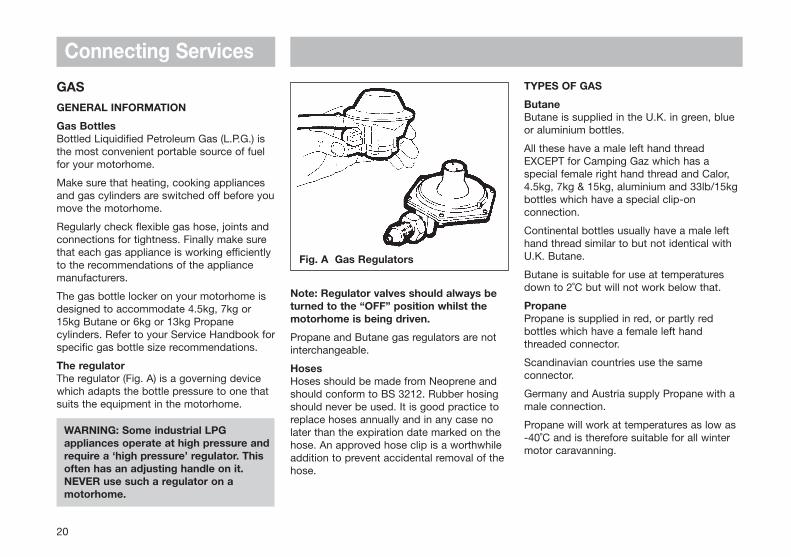
The regulatorThe regulator (Fig. A) is a governing devicewhich adapts the bottle pressure to one thatsuits the equipment in the motorhome.
WARNING: Some industrial LPG appliances operate at high pressure and require a ‘high pressure’ regulator. This often has an adjusting handle on it. NEVER use such a regulator on a motorhome.
Note: Regulator valves should always beturned to the “OFF” position whilst themotorhome is being driven.
Propane and Butane gas regulators are notinterchangeable.
HosesHoses should be made from Neoprene andshould conform to BS 3212. Rubber hosingshould never be used. It is good practice toreplace hoses annually and in any case nolater than the expiration date marked on thehose. An approved hose clip is a worthwhileaddition to prevent accidental removal of thehose.
TYPES OF GAS
ButaneButane is supplied in the U.K. in green, blueor aluminium bottles.
All these have a male left hand threadEXCEPT for Camping Gaz which has aspecial female right hand thread and Calor,4.5kg, 7kg & 15kg, aluminium and 33lb/15kgbottles which have a special clip-onconnection.
Continental bottles usually have a male lefthand thread similar to but not identical withU.K. Butane.
Butane is suitable for use at temperaturesdown to 2˚C but will not work below that.
PropanePropane is supplied in red, or partly redbottles which have a female left handthreaded connector.
Scandinavian countries use the sameconnector.
Germany and Austria supply Propane with amale connection.
Propane will work at temperatures as low as -40˚C and is therefore suitable for all wintermotor caravanning.
Connecting Services
20
Fig. A Gas Regulators
Connecting Services
21
GAS SAFETY ADVICE
Facts about LPGLPG is not poisonous.
Bi-products are harmless.
There is danger if all air and oxygen areexcluded.
(Ventilation holes must be kept clear at alltimes).
LPG has been given a smell by themanufacturers in order to identify leaks.
Awning Spaces LPG Appliance ExhaustThere is no danger of pollution of anenclosed awning space by the LPG exhaustfrom a refrigerator venting into it.
Space heaters may produce sufficientexhaust to pollute the awning space, if it istotally enclosed, from a general comfort,smell and hygiene point of view. In extremecases there could be a build up of carbondioxide to a dangerous level.
Motorhome owners are advised to allowsome fresh air circulation in the awningspace when such appliances are in use.
PRECAUTIONS
a) Never look for a leak with a match. Always use a soap solution or its equivalent when testing connections. Do not operate any electrical apparatus whatsoever, especially light switches.
If the leak is not obvious, the motorhome should be evacuated and qualified personnel consulted.
b) Avoid naked lights when connecting or changing a cylinder.
c) Check the flexible hose frequently.
d) Gas is heavier than air and therefore sinks to the lowest point.
e) Keep bottle gas containers outside (and protected against frost). If they must be kept inside make sure they are well away from heat.
WARNING: If you smell gas or suspect a leak and if it is safe to do so, isolate the gas appliances and turn off the gas bottles at the regulator. Evacuate the motorhome and ventilate the vehicle. Seek professional advice as to the cause of the leak.
WARNING: Inspect flexible gas hose regularly for deterioration and renew as necessary, with the approved type, in any case not later than the expiry date marked on the hose. Flexible gas hose length should not exceed 400mm.
VentilationVents should not be obstructed in anymanner as this could lead to insufficientfresh air. In this case the confined
atmosphere becomes depleted of oxygenwhich leads to the formation of the highlypoisonous gas ‘carbon monoxide’. CarbonMonoxide is odourless, colourless andtasteless and will rapidly causeunconsciousness and death with little or nowarning prior to collapse.
THERE IS NO DANGER WHEN ADEQUATEVENTILATION IS PROVIDED.
Roof-mounted Flue InstallationsAll flue installations should be inspectedonce a year throughout their length forcorrosion. Flues should be replaced if anysign of perforation is found. Ensure that thereplacement is of an approved type.
ConnectionEnsure that the gas regulator is correctlyconnected to the gas cylinder in the gasbottle compartment and that the hose istight. Before turning on the gas supply,ensure that all gas operated equipment inthe motorhome is turned off.
Gas Tap ColoursAll gas equipment is supplied through a gasmanifold system which has individualisolation taps for each appliance as follows:
Red - Water HeaterWhite - Space HeaterGreen - Hob & Oven (combination)Green - Hob (separate)Yellow - Oven (separate)Blue - Fridge
ELECTRICITYAs with electricity in the home, care must beexercised when handling mains electricity.
Your attention is drawn to the followingnotice as laid down by the Institute ofElectrical Engineers.
INSTRUCTIONS FOR ELECTRICITYSUPPLY
On arrival at site1. Before connecting the motorhome
installation to the mains supply, check that:
(a) the mains supply is suitable for your installation and appliances, i.e. whether it is a.c. or d.c. and whether it is at the correct voltage and frequency, and
(b) your installation will be properly earthed. Never accept a supply from asocket outlet or plug having only two pins, or from a lighting outlet.
(c) any residual current device (earth leakage circuit breaker) in the mains supply to the motorhome has been tested within the last month.
In case of doubt, consult the site owner or his agent.
2. MAKE SURE THAT THE SWITCH AT THE SITE SUPPLY POINT IS OFF.
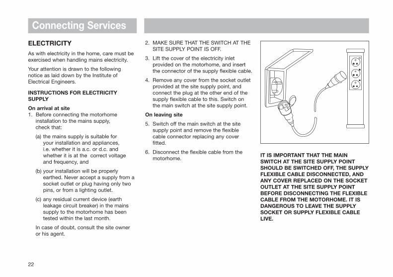
3. Lift the cover of the electricity inlet provided on the motorhome, and insert the connector of the supply flexible cable.
4. Remove any cover from the socket outlet provided at the site supply point, and connect the plug at the other end of the supply flexible cable to this. Switch on the main switch at the site supply point.
On leaving site
5. Switch off the main switch at the site supply point and remove the flexible cable connector replacing any cover fitted.
6. Disconnect the flexible cable from the motorhome.
IT IS IMPORTANT THAT THE MAINSWITCH AT THE SITE SUPPLY POINTSHOULD BE SWITCHED OFF, THE SUPPLYFLEXIBLE CABLE DISCONNECTED, ANDANY COVER REPLACED ON THE SOCKETOUTLET AT THE SITE SUPPLY POINTBEFORE DISCONNECTING THE FLEXIBLECABLE FROM THE MOTORHOME. IT ISDANGEROUS TO LEAVE THE SUPPLYSOCKET OR SUPPLY FLEXIBLE CABLELIVE.
Connecting Services
22
Connecting Services
23
For motorhomes that are generally leftunused for long periods in the open it isstrongly advised that the mains installation isinspected periodically to ensure that it issafe to use. The IEE Wiring Regulationsrecommend that mains installations inmotorhomes are re-inspected every 3 years.An annual inspection by a qualified person isrecommended (see list below) who shouldsign and issue a periodic inspection report.
Suitably qualified persons acceptable to theSMMT/NCC to sign and issue Inspectionand Completion Certificates should be oneof the following:
• An approved contractor of the National Inspection Council for Electrical Installation Contracting* or
• A member of the Electrical Contractors’ Association of Scotland
• A qualified person acting on behalf of the above (in which event it should be stated for whom he is acting).
• The names and addresses of Approved Contractors in any locality (there are over 10,500 in the UK) can be obtained from Electricity Shops, or direct from:
NICEICVintage House37 Albert EmbankmentLondon SE1 7UJTelephone: 0207 564 2323
The names and addresses of members ofthe Electrical Contractors’ Associations canbe obtained direct from:
ECAEsca HousePalace CourtLondon W2 4HYTelephone: 0207 313 4800
ECA of Scotland23 Heriot RowEdinburgh EH3 6EWTelephone: 0131 225 7221
IN CASE OF DIFFICULTY CONSULT ANAPPROVED ELECTRICAL INSTALLATIONCONTRACTOR (WHO MAY BE THELOCAL ELECTRICITY COMPANY). IT ISDANGEROUS TO ATTEMPTMODIFICATIONS AND ADDITIONSYOURSELF. LAMPHOLDER-PLUGS(BAYONET CAP ADAPTORS) SHOULDNOT, IN ANY CIRCUMSTANCES, BEUSED.
OVERSEAS CONNECTIONNote: Connection to a mains voltage supplyOVERSEAS requires particular attention.
Care must be taken when connectingsupplies abroad since the supplies can be ofREVERSE POLARITY.
The significance of REVERSE POLARITY isthat when equipment is switched off it maynot be electrically isolated.
The only certain way of making equipmentsafe is to unplug it.
If electrical polarity indication is not includedin your motorhome electrical equipment, it isuseful to have a means of checking polarityof the mains supply, especially when touringoverseas.
There are available several proprietary makesof equipment for the purpose.
If it can be achieved, it is preferable toconnect live to live, and neutral to neutral tomaintain full electrical protection.
CHECK all motorhome equipment is set-upto accept the site supply before actuallyswitching on.
Connecting Services
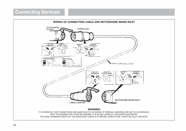
WIRING OF CONNECTING CABLE AND MOTORHOME MAINS INLET
WARNINGIT IS ESSENTIAL THAT CONNECTIONS ARE MADE EXACTLY AS SHOWN. IF TERMINAL MARKINGS ARE NOT IN ACCORDANCE
WITH THE DIAGRAM THEY MUST BE IGNORED. IF IN DOUBT CONSULT A QUALIFIED ELECTRICIAN.THE LEGAL MAXIMUM LENGTH OF THE MAINS INLET CABLE IS 25 METRES. WHEN IN USE IT MUST BE FULLY UNCOILED.
24
MOTORHOME MAINS INLETCABLE COUPLER
Connecting Services
25
230V MAINS ELECTRICALEQUIPMENT POWERCONSUMPTIONPlease note:It is possible that the 230V mains electricalequipment may not all operatesimultaneously. A typical UK motorhome sitemains hook up point provides a maximumoutput of 10 amps and on some continentalsites the available output may be as low as 5amps. If your loading exceeds the sitesupply it may trip the site circuit breaker.Please check the available mains output withyour site operator.
The following items need to be addedtogether if used simultaneously.
230V Mains equipment typicalconsumption figures:
Water heater 3.6A approx.
Travelling kettle 3.2A approx.
Battery charger 1.0A approx.
Portable colour TV 0.3A approx.
60w light bulb 0.3A approx.
Ultraheat 500W 2.2A approx.
Ultraheat 1000W 4.5A approx.
Ultraheat 2000W 8.5A approx.
THERMAL INSULATION ANDHEATINGYour motorhome has been designed toachieve a thermal insulation and heatinglevel for specific climatic conditions whentested according to the procedure inEN1646-1. The classifications are as follows:
Grade 1A motorhome with an average thermaltransmittance (u) that does not exceed1.7w/(m2K).
Grade 2A motorhome with an average thermaltransmittance (u) that does not exceed1.7w/(m2K) and which can achieve anaverage temperature difference of at least20K between inside and outsidetemperatures when the outside temperatureis 0°C.
Grade 3A motorhome with an average thermaltransmittance (u) that does not exceed1.2w/(m2K) and which can achieve anaverage temperature difference of at least35K between inside and outsidetemperatures when the outside temperatureis -15°C.
WARNING: Never allow modifications of electrical or LPG systems andappliances except by qualified persons.

ELECTRICALSYSTEMS
Motorhome Battery ................................................................ 28
Fault Finding ........................................................................... 28
Mains Unit ............................................................................... 29
12V Power System ................................................................. 30
Transformer/Charger Unit ...................................................... 30
The EC200 Electronic Control System ................................. 30
System overview .................................................................. 31
Power supply unit - System operation ..................................31
Control panel operation .........................................................36
Technical data and approvals ................................................40
Generator Guidelines ............................................................. 42
Electrical Systems
28
MOTORHOME BATTERY
It is recommended that a good qualityleisure battery is always in circuit when thesystem is in use.
A deep cycling heavy duty 12V batteryshould be used to provide power for lightsand other electrical appliances. A proprietarybrand leisure battery with 85A capacity isrecommended. (It must have tube ventingcapability for internal battery boxes.)
It should be remembered that batteriessuitable for the electrical demands of amotorhome differ in design from those foruse with a car, and whilst the system mayoperate with a car battery, it is stronglyrecommended that only a leisure typebattery, maintained in good condition isused.
The battery should be vented to the outsideand should be properly secured. Whenconnecting the battery, ensure that thecorrect polarity is observed (black isnegative and red is positive), and that theterminals are securely fastened.
Under normal circumstances it should not benecessary to remove the battery other thanfor routine inspection of terminals.
WARNING: Explosive gases may be present at battery - prevent flames and sparks.
Do not store highly flammable materials or pressurised containers in this area.
WARNING: Switch off all appliances and lamps before disconnecting the battery.
Smoking is prohibited around the battery compartment.
Your motorhome has been fitted with an in-line fuse next to the + battery terminal. It isrecommended that the rating of the fusefitted in this location does not exceed 20A.
Please note the leisure battery, where factoryfitted, is not charged and should be chargedfor a minimum of 24 hours before use.
When fitting the battery, ensure that thecorrect polarity is observed and thatterminals are securely fastened.
Ensure the battery is secured with the strapprovided.
FAULT FINDING
1. Mains supplyIf mains supply is not available when mains switch and MCB’s are switched on, check supply at site distribution and/or mains lead and connections.
2. Earth faults or MCB trippedSee RCD/MCD Section.
3. Charger switch fails to illuminateCheck mains supply as for No.1 and 2.
4. Battery discharged or not charging with charger onCheck battery terminals.
5. 12V distribution circuit failureCheck and replace relevant DC output fuse as required.
6. Consult the manufacturers regarding any further difficulties, in particular those related to mains voltage section.
7. There are no user-serviceable orreplacement parts in the consumer unit. All service of this nature should be referred to the manufacturers.
Note: Never use a mains supply lead whilstcoiled. Always uncoil the full length beforeconnecting to the supply and remember toprotect the cable from traffic.
PLUG-IN-SYSTEMS LIMITED PROVIDE AN ON-CALL SERVICE FOR WARRANTYOR NON-WARRANTY REPAIRS.
IF YOU WISH TO TAKE ADVANTAGE OFTHIS SERVICE FOR PLUG-IN-SYSTEMSEQUIPMENT ONLY:
Telephone: (01482) 652523 and ask forDIRECT SERVICES.
Electrical Systems
If an earth fault develops or a person touchesa live piece of equipment the leakage ofcurrent to earth should immediately operatethe RCD (residual current device) and ‘trip’the main switch, to the OFF position.
This switch is only re-settable afterelimination of the fault.
To re-set, operate the switch as for MCB’s.
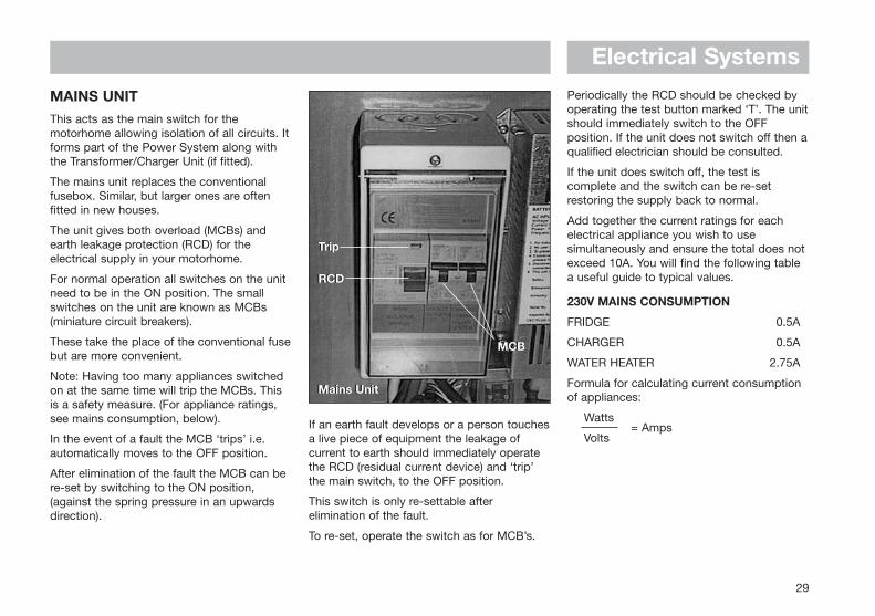
MAINS UNITThis acts as the main switch for themotorhome allowing isolation of all circuits. Itforms part of the Power System along withthe Transformer/Charger Unit (if fitted).
The mains unit replaces the conventionalfusebox. Similar, but larger ones are oftenfitted in new houses.
The unit gives both overload (MCBs) andearth leakage protection (RCD) for theelectrical supply in your motorhome.
For normal operation all switches on the unitneed to be in the ON position. The smallswitches on the unit are known as MCBs(miniature circuit breakers).
These take the place of the conventional fusebut are more convenient.
Note: Having too many appliances switchedon at the same time will trip the MCBs. Thisis a safety measure. (For appliance ratings,see mains consumption, below).
In the event of a fault the MCB ‘trips’ i.e.automatically moves to the OFF position.
After elimination of the fault the MCB can bere-set by switching to the ON position,(against the spring pressure in an upwardsdirection).
Periodically the RCD should be checked byoperating the test button marked ‘T’. The unitshould immediately switch to the OFFposition. If the unit does not switch off then aqualified electrician should be consulted.
If the unit does switch off, the test iscomplete and the switch can be re-setrestoring the supply back to normal.
Add together the current ratings for eachelectrical appliance you wish to usesimultaneously and ensure the total does notexceed 10A. You will find the following tablea useful guide to typical values.
230V MAINS CONSUMPTION
FRIDGE 0.5A
CHARGER 0.5A
WATER HEATER 2.75A
Formula for calculating current consumptionof appliances:
Watts
Volts = Amps
29
Mains Unit
RCD
Trip
MCB
Mains Unit
RCD
Trip
MCB

Electrical Systems
12V POWER SYSTEMNote: The connection of the battery chargerto the mains supply is in accordance with theRegulations for Electrical Installations 16thEdition (IEE Wiring Regulations) BS 7671:1992.
The Power System is supplied fitted remotelyin a convenient position and comprises:
(a) Mains Unit
(b) Transformer/Charger Unit
TRANSFORMER/CHARGER UNIT The transformer/charger unit has importantsafety features:
• Overload protection
• Short circuit protection
• Reverse battery polarity protection
The unit has been designed not only tooperate as a battery charger, but also for useas a power supply, should a 12V DC batterynot be present in circuit. It is, however,recommended that a good quality leisurebattery is installed.
Once connected to a 230V mains supply andswitched on, its operation is fully automatic.
To charge either battery, position the batteryselector switch to the appropriate position onthe distribution panel.
The facility for drawing 12V supply from thecab battery is intended for standby situationsonly, and care should be taken not to run thecab battery too low, some models featurecab battery protection circuitry.
If the cab battery has been used on site, thenthe engine driven alternator will rechargeboth it and the caravan battery whilsttravelling.
However, once the cab battery is fullycharged, the alternator will supply a tricklecharge only to the caravan battery.
This will take place regardless of the positionof the battery selector switch on thedistribution panel.
1. INTRODUCING THE EC200ELECTRONIC CONTROL SYSTEMWith the use of new technology and aninnovative approach to user interfacing, theEC200 Power Control System provides acomplete control solution for a wide range ofleisure vehicles.
The microprocessor controlled digital systemallows the user to control equipment andview / edit system information from a user-friendly control panel that incorporates aliquid crystal ‘ALPHA-NUMERIC’ display.
The built in ‘intelligence’ prevents overdischarge of the vehicle battery, allowsgreater control of the water system and has abuilt in alarm clock. With the addition of an
When used as an alternative DC powersupply, with no battery in circuit, the willsupply a suitable output for use with pump,lighting, T.V., radio etc. Should the unitbecome overloaded the 12A DC fuse willblow. Removal of the overload or fault allowsthe unit to return to normal operation, afterreplacing the DC fuse. A 1A anti-surge ACfuse is provided as further protection.
Under normal circumstances the total loadrequired by motorhome equipment shouldnot produce an overload situation.
30
Charger/TransformerCharger/Transformer
Electrical Systemsoptional plug-in remote control pack thePower and Auxiliary functions can beoperated by a key fob controller.
The system meets relevant UK legislation,including the requirements of BS7671,EN1648-1 and -2. Further technical data iscontained in section 5.
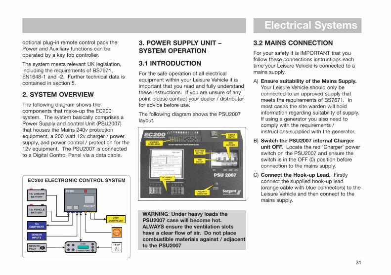
2. SYSTEM OVERVIEWThe following diagram shows thecomponents that make-up the EC200system. The system basically comprises aPower Supply and control Unit (PSU2007)that houses the Mains 240v protectionequipment, a 200 watt 12v charger / powersupply, and power control / protection for the12v equipment. The PSU2007 is connectedto a Digital Control Panel via a data cable.
3. POWER SUPPLY UNIT –SYSTEM OPERATION
3.1 INTRODUCTIONFor the safe operation of all electricalequipment within your Leisure Vehicle it isimportant that you read and fully understandthese instructions. If you are unsure of anypoint please contact your dealer / distributorfor advice before use.
The following diagram shows the PSU2007layout.
WARNING: Under heavy loads thePSU2007 case will become hot.ALWAYS ensure the ventilation slotshave a clear flow of air. Do not placecombustible materials against / adjacentto the PSU2007
3.2 MAINS CONNECTIONFor your safety it is IMPORTANT that youfollow these connections instructions eachtime your Leisure Vehicle is connected to amains supply.
A) Ensure suitability of the Mains Supply.Your Leisure Vehicle should only beconnected to an approved supply thatmeets the requirements of BS7671. Inmost cases the site warden will holdinformation regarding suitability of supply.If using a generator you also need tocomply with the requirements /instructions supplied with the generator.
B) Switch the PSU2007 internal Chargerunit OFF. Locate the red ‘Charger’ powerswitch on the PSU2007 and ensure theswitch is in the OFF (0) position beforeconnection to the mains supply.
C) Connect the Hook-up Lead. Firstlyconnect the supplied hook-up lead(orange cable with blue connectors) to theLeisure Vehicle and then connect to themains supply.
31
POWERSWITCH
RCD TESTBUTTON
RCDSWITCH
MCBSWITCHES
POLARITYINDICATOR
DC SUPPLYFUSES
CHARGERVENTILATION
Electrical SystemsD) Check Residual Current Device
operation. Locate the RCD within thePSU2007 and ensure the RCD is switchedon (lever in up position). Press the ‘TEST’button and confirm that the RCD is turnedoff (lever in down position). Switch theRCD back to the on position (lever in upposition). If the test button failed tooperate the RCD see section 3.4.
E) Check correct Polarity. Locate the‘Reverse Polarity’ indicator on thePSU2007 and ensure that the indicator isNOT illuminated. If the indicator isilluminated see section 3.4.
F) Check Miniature Circuit Breakers.Locate the MCB’s within the PSU2007(adjacent to the RCD) and ensure they areall in the ON (up) position. If any MCB’sfail to latch in the on position see section3.4.
G) Turn the PSU2007 ON. Locate the redpower switch on the PSU2007 and turn tothe ON (I) position. The switch willilluminate when turned on.
H) Check operation of equipment. It isnow safe to check the operation of the12v and 240v equipment.
3.3 BATTERYA) Type / Selection
For optimum performance and safety it is
essential that only a proprietary brandLEISURE battery is used with a typicalcapacity of 75 to 120 Ah (Ampere / hours).A normal car battery is NOT suitable.
It is recommended that the leisure battery isalways ‘in circuit’ when the system is in use.
The battery feed is fitted with an inline fusebetween the battery and the electricalharness, and is usually located immediatelyoutside the battery compartment or within500mm of the battery. The maximum ratingof this fuse is 20A.
B) Installation & Removal
Always disconnect the 240v mains supplyand turn the PSU 2007 charger switch to theOFF (0) position before removing or installingthe battery.
When connecting the battery, ensure that thecorrect polarity is observed (black is negative[-] and red is positive [+]) and that theterminals are securely fastened. Crocodileclips must not be used.
WARNING: Explosive gases may bepresent at the battery. Take care to prevent flames and sparks in the vicinity of the battery and do not smoke.
C) Servicing
Under normal circumstances it should not benecessary to remove the battery other than
for routine inspection of the terminals and“topping up” of the battery fluid whereapplicable. Please see instructions suppliedwith the battery.
Note: Do not over-discharge the battery.One of the most common causes of batteryfailure is when the battery is dischargedbelow the recommended level ofapproximately 10.5v. Discharging a batterybelow this figure can cause permanentdamage to one or more of the cells withinthe battery.
32
Electrical Systems
33
Fault
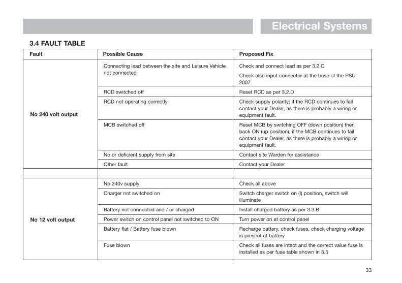
3.4 FAULT TABLE
Possible Cause Proposed Fix
No 240 volt output
No 12 volt output
Connecting lead between the site and Leisure Vehiclenot connected
RCD switched off
RCD not operating correctly
MCB switched off
No or deficient supply from site
Other fault
No 240v supply
Charger not switched on
Battery not connected and / or charged
Power switch on control panel not switched to ON
Battery flat / Battery fuse blown
Fuse blown
Check and connect lead as per 3.2.C
Check also input connector at the base of the PSU2007
Reset RCD as per 3.2.D
Check supply polarity; if the RCD continues to failcontact your Dealer, as there is probably a wiring orequipment fault.
Reset MCB by switching OFF (down position) thenback ON (up position), if the MCB continues to failcontact your Dealer, as there is probably a wiring orequipment fault.
Contact site Warden for assistance
Contact your Dealer
Check all above
Switch charger switch on (I) position, switch willilluminate
Install charged battery as per 3.3.B
Turn power on at control panel
Recharge battery, check fuses, check charging voltageis present at battery
Check all fuses are intact and the correct value fuse isinstalled as per fuse table shown in 3.5
Electrical Systems
34
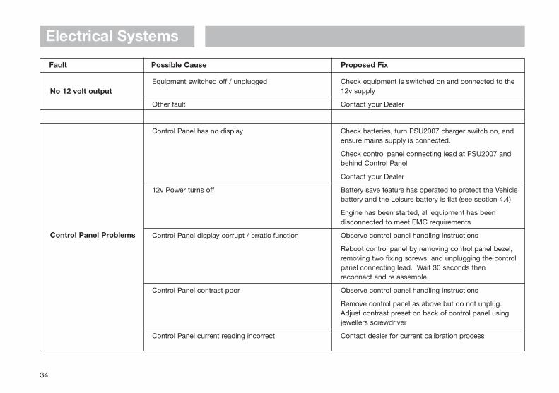
Fault Possible Cause Proposed Fix
No 12 volt output
Control Panel Problems
Equipment switched off / unplugged
Other fault
Control Panel has no display
12v Power turns off
Control Panel display corrupt / erratic function
Control Panel contrast poor
Control Panel current reading incorrect
Check equipment is switched on and connected to the12v supply
Contact your Dealer
Check batteries, turn PSU2007 charger switch on, andensure mains supply is connected.
Check control panel connecting lead at PSU2007 andbehind Control Panel
Contact your Dealer
Battery save feature has operated to protect the Vehiclebattery and the Leisure battery is flat (see section 4.4)
Engine has been started, all equipment has beendisconnected to meet EMC requirements
Observe control panel handling instructions
Reboot control panel by removing control panel bezel,removing two fixing screws, and unplugging the controlpanel connecting lead. Wait 30 seconds thenreconnect and re assemble.
Observe control panel handling instructions
Remove control panel as above but do not unplug.Adjust contrast preset on back of control panel usingjewellers screwdriver
Contact dealer for current calibration process
Electrical Systems
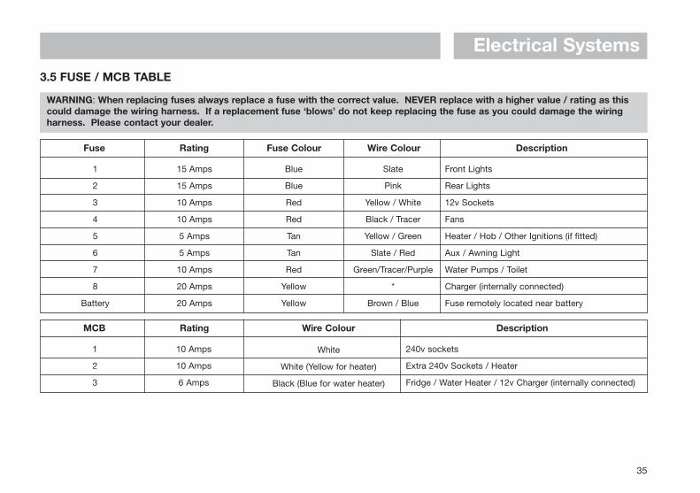
3.5 FUSE / MCB TABLE
WARNING: When replacing fuses always replace a fuse with the correct value. NEVER replace with a higher value / rating as thiscould damage the wiring harness. If a replacement fuse ‘blows’ do not keep replacing the fuse as you could damage the wiringharness. Please contact your dealer.
35
Fuse Rating Fuse Colour Wire Colour Description
1
2
3
4
5
6
7
8
Battery
15 Amps
15 Amps
10 Amps
10 Amps
5 Amps
5 Amps
10 Amps
20 Amps
20 Amps
Blue
Blue
Red
Red
Tan
Tan
Red
Yellow
Yellow
Slate
Pink
Yellow / White
Black / Tracer
Yellow / Green
Slate / Red
Green/Tracer/Purple
*
Brown / Blue
Front Lights
Rear Lights
12v Sockets
Fans
Heater / Hob / Other Ignitions (if fitted)
Aux / Awning Light
Water Pumps / Toilet
Charger (internally connected)
Fuse remotely located near battery
MCB Rating Wire Colour
White
White (Yellow for heater)
Black (Blue for water heater)
Description
1
2
3
10 Amps
10 Amps
6 Amps
240v sockets
Extra 240v Sockets / Heater
Fridge / Water Heater / 12v Charger (internally connected)
Electrical Systems
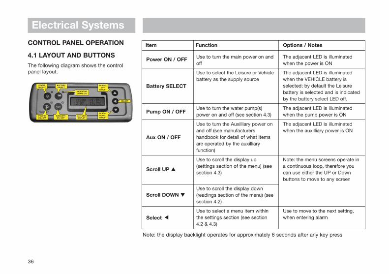
CONTROL PANEL OPERATION
4.1 LAYOUT AND BUTTONSThe following diagram shows the controlpanel layout.
36
Item Function Options / Notes
Power ON / OFF
Battery SELECT
Pump ON / OFF
Aux ON / OFF
Scroll UP s
Scroll DOWN t
Select
Use to turn the main power on andoff
Use to select the Leisure or Vehiclebattery as the supply source
Use to turn the water pump(s)power on and off (see section 4.3)
Use to turn the Auxilliary power onand off (see manufacturershandbook for detail of what itemsare operated by the auxilliaryfunction)
Use to scroll the display up(settings section of the menu) (seesection 4.3)
Use to scroll the display down(readings section of the menu) (seesection 4.2)
Use to select a menu item withinthe settings section (see section4.2 & 4.3)
The adjacent LED is illuminatedwhen the power is ON
The adjacent LED is illuminatedwhen the VEHICLE battery isselected; by default the Leisurebattery is selected and is indicatedby the battery select LED off.
The adjacent LED is illuminatedwhen the pump power is ON
The adjacent LED is illuminatedwhen the auxilliary power is ON
Note: the menu screens operate ina continuous loop, therefore youcan use either the UP or Downbuttons to move to any screen
Use to move to the next setting,when entering alarm
t
Note: the display backlight operates for approximately 6 seconds after any key press
Electrical Systems
37
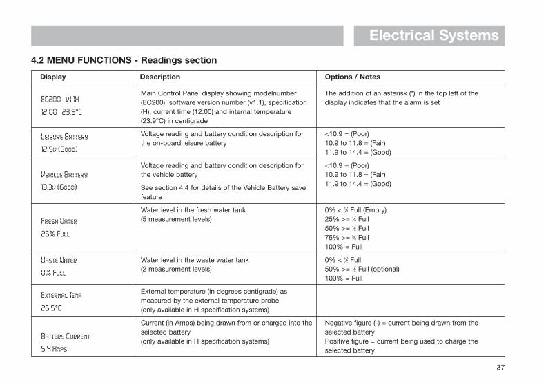
Display Description Options / Notes
EC200 v1.1H
12:00 23.9°C
Leisure Battery
12.5v (Good)
Vehicle Battery
13.3v (Good)
Fresh Water
25% Full
Waste Water
0% Full
External Temp
26.5°C
Battery Current
5.4 Amps
Main Control Panel display showing modelnumber(EC200), software version number (v1.1), specification(H), current time (12:00) and internal temperature(23.9°C) in centigrade
Voltage reading and battery condition description forthe on-board leisure battery
Voltage reading and battery condition description forthe vehicle battery
See section 4.4 for details of the Vehicle Battery savefeature
Water level in the fresh water tank(5 measurement levels)
Water level in the waste water tank(2 measurement levels)
External temperature (in degrees centigrade) asmeasured by the external temperature probe(only available in H specification systems)
Current (in Amps) being drawn from or charged into theselected battery(only available in H specification systems)
The addition of an asterisk (*) in the top left of thedisplay indicates that the alarm is set
<10.9 = (Poor)10.9 to 11.8 = (Fair)11.9 to 14.4 = (Good)
<10.9 = (Poor)10.9 to 11.8 = (Fair)11.9 to 14.4 = (Good)
0% < 1⁄4 Full (Empty)25% >= 1⁄4 Full50% >= 1⁄2 Full75% >= 3⁄4 Full100% = Full
0% < 1⁄2 Full50% >= 1⁄2 Full (optional)100% = Full
Negative figure (-) = current being drawn from theselected batteryPositive figure = current being used to charge theselected battery
4.2 MENU FUNCTIONS - Readings section
Electrical Systems
38
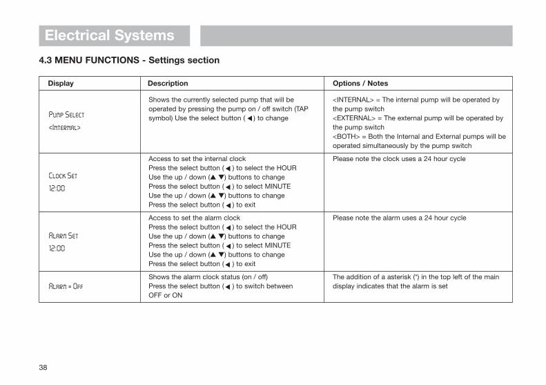
Display Description Options / Notes
Pump Select
<Internal>
Clock Set
12:00
Alarm Set
12:00
Alarm = Off
Shows the currently selected pump that will beoperated by pressing the pump on / off switch (TAPsymbol) Use the select button ( ) to change
Access to set the internal clockPress the select button ( ) to select the HOURUse the up / down (s t) buttons to changePress the select button ( ) to select MINUTEUse the up / down (s t) buttons to changePress the select button ( ) to exit
Access to set the alarm clockPress the select button ( ) to select the HOURUse the up / down (s t) buttons to changePress the select button ( ) to select MINUTEUse the up / down (s t) buttons to changePress the select button ( ) to exit
Shows the alarm clock status (on / off)Press the select button ( ) to switch betweenOFF or ON
<INTERNAL> = The internal pump will be operated bythe pump switch<EXTERNAL> = The external pump will be operated bythe pump switch<BOTH> = Both the Internal and External pumps will beoperated simultaneously by the pump switch
Please note the clock uses a 24 hour cycle
Please note the alarm uses a 24 hour cycle
The addition of a asterisk (*) in the top left of the maindisplay indicates that the alarm is set
4.3 MENU FUNCTIONS - Settings section
s
ss
ss
ss
s
Electrical Systems
39
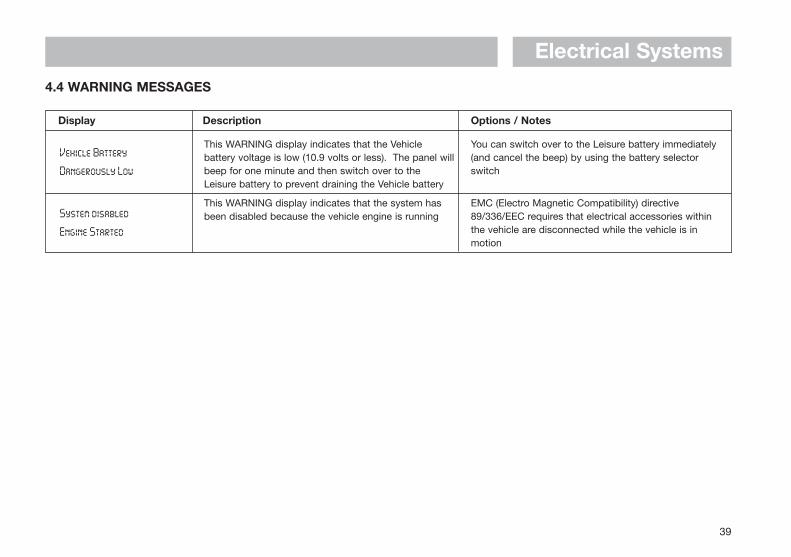
Display Description Options / Notes
Vehicle Battery
Dangerously Low
System disabled
Engine Started
This WARNING display indicates that the Vehiclebattery voltage is low (10.9 volts or less). The panel willbeep for one minute and then switch over to theLeisure battery to prevent draining the Vehicle battery
This WARNING display indicates that the system hasbeen disabled because the vehicle engine is running
You can switch over to the Leisure battery immediately(and cancel the beep) by using the battery selectorswitch
EMC (Electro Magnetic Compatibility) directive89/336/EEC requires that electrical accessories withinthe vehicle are disconnected while the vehicle is inmotion
4.4 WARNING MESSAGES
Electrical Systems
40
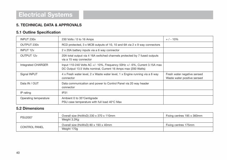
PSU2007
CONTROL PANEL
Overall size (HxWxD) 230 x 370 x 110mmWeight 3.2Kg
Overall size (HxWxD) 80 x 193 x 40mmWeight 170g
Fixing centres 195 x 360mm
Fixing centres 175mm
5.2 Dimensions
INPUT 230v
OUTPUT 230v
INPUT 12v
OUTPUT 12v
Integrated CHARGER
Signal INPUT
Data IN / OUT
IP rating
Operating temperature
230 Volts / 0 to 16 Amps
RCD protected, 3 x MCB outputs of 10, 10 and 6A via 2 x 9 way connectors
2 x 20A battery inputs via a 6 way connector
20A total output via 4 16A switched channels protected by 7 fused outputsvia a 15 way connector
Input 110-240 Volts AC +/- 10%, Frequency 50Hz +/- 6%, Current 3.15A maxDC Output 13.5 Volts nominal, Current 16 Amps max (200 Watts)
4 x Fresh water level, 2 x Waste water level, 1 x Engine running via a 8 wayconnector
Data communication and power to Control Panel via 20 way headerconnector
IP31
Ambient 0 to 35°CentigradePSU case temperature with full load 40°C Max
+ / - 10%
Fresh water negative sensedWaste water positive sensed
5. TECHNICAL DATA & APPROVALS
5.1 Outline Specification
Electrical Systems
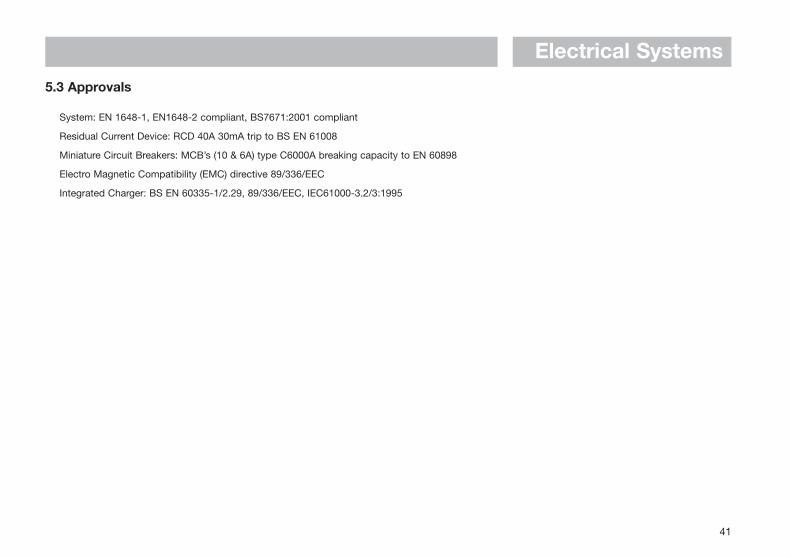
41
System: EN 1648-1, EN1648-2 compliant, BS7671:2001 compliant
Residual Current Device: RCD 40A 30mA trip to BS EN 61008
Miniature Circuit Breakers: MCB’s (10 & 6A) type C6000A breaking capacity to EN 60898
Electro Magnetic Compatibility (EMC) directive 89/336/EEC
Integrated Charger: BS EN 60335-1/2.29, 89/336/EEC, IEC61000-3.2/3:1995
5.3 Approvals
Electrical Systems
GENERATOR GUIDELINES• Lack of regular servicing can be the cause
of most generator problems, gensetsunder 2kW are mainly dependent onengine speed for output frequency andvoltage. Poor or no servicing may causethe engine speed governor to run thegenset to fast. Therefore, frequency andoutput voltage can rise above thespecification of the machine data plate i.e.
230V at 50Hz. This may cause damage toelectrical/electronic equipment (such asbattery chargers).
• A generator should always run for a fewminutes prior to connection with themotorhome electrics, to allow it to warmup and the output to settle to a steadylevel.
• The AC output of generators is oftenderived from an AC alternator, rectified to
DC then inverted back to AC. In essencethis means the output sinewave may notrun sophisticated electronics efficiently.Some of the new wave of gensets aremore sophisticated in their production of asinewave output and are more suited torun electronic equipment.
• If in doubt consult your genset dealer ormanufacturer for advice
42
EQUIPMENTDETAILS
Water Pump (Shurflo) ............................................................. 44Truma Ultrastore...................................................................... 44Refrigerators ........................................................................... 47
Models RM6270, RM6271, RM6361, RM6401, RM6291 ................................................................. 48Model RM6501 ..................................................................... 52Model RM4212 and RM4213.................................................51General information .............................................................. 52
SMEV 400 Series Cooker ....................................................... 54Stoves Hobs, Grills and Ovens ............................................. 56Dometic Extractor Fan .......................................................... 60Thetford Cassette Porta Potti ............................................... 61Heating .................................................................................... 68
Trumatic C3402 & C6002 ..................................................... 68Truma S 3002 Heater .......................................................... 75Truma Ultraheat .................................................................... 77
Butterfly Outlets ......................................................................78Front Swivel Seat ................................................................... 78Side Locker ............................................................................. 78Tables ...................................................................................... 79Rooflights & Windows..............................................................79Shower.......................................................................................81Omnistep Slide-out ..................................................................82
Equipment DetailsIMPORTANT
To maximise the use and life of all fittedequipment in your motorhome it is essentialthat any accompanying manufacturers’literature is read fully. All recommendedmaintenance and preparation proceduresshould be followed. The information providedin this handbook is only intended as a guide.If in any doubt consult your Swift Groupappointed dealer, particularly beforeattempting to install EXTRA EQUIPMENT.
SHURFLO WATER PUMPThis pump is a completely sealed unitdesigned for intermittent use and is self-priming.
THE TRUMA ULTRASTOREWATER HEATEROPERATING INSTRUCTIONS
When connecting to a central water supply(rural or city connection) or when using morepowerful pumps, a pressure reducer must beused which prevents pressures of greaterthan 2.8 bar occurring in the Ultrastore.
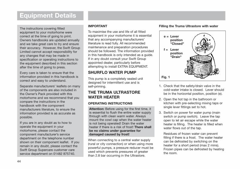
Filling the Truma Ultrastore with water
1. Check that the safety/drain valve in the cold-water intake is closed. Lever should be in the horizontal position, position (e).
2. Open the hot tap in the bathroom or kitchen with pre-selecting mixing taps or single lever fittings set to hot.
3. Switch on power for water pump (main switch or pump switch). Leave the tap open to let air escape while the water heater is filling. The heater is filled when water flows out of the tap.
Residues of frozen water can prevent filling if there is a frost. The water heater can be defrosted by switching on the heater for a short period (max 2 mins). Frozen pipes can be defrosted by heating the room.
44
e = Lever position "Closed"
f = Lever position "Drain"
Fig. 1
The instructions covering fittedequipment to your motorhome werecorrect at the time of going to print.Owners handbooks are updated annuallyand we take great care to try and ensuretheir accuracy. However, the Swift GroupLimited cannot accept responsibility forany changes that may be made inspecification or operating instructions tothe equipment described in this sectionafter the time of going to press.
Every care is taken to ensure that theinformation provided in this handbook iscorrect and easy to understand.
Separate manufacturers’ leaflets on manyof the components are also included inthe Owner’s Pack provided with thismotorhome and we recommend that youcompare the instructions in thehandbook with the componentmanufacturers literature, to ensure theinformation provided is as accurate aspossible.
If you are in any doubt as to how tooperate the equipment in yourmotorhome, please contact thecomponent manufacturer’s servicedepartment on the telephone numbershown on their component leaflet. If youremain in any doubt, please contact theSwift Group Supercare customer careservice department on 01482 875740.
Attention: Before using for the first time, it is essential to flush the entire water supplythrough with clean warm water. Alwaysmount the cowl cap when the water heater is not being operated! Drain the waterheater if there is a risk of frost! There shallbe no claims under guarantee fordamaged caused by frost!
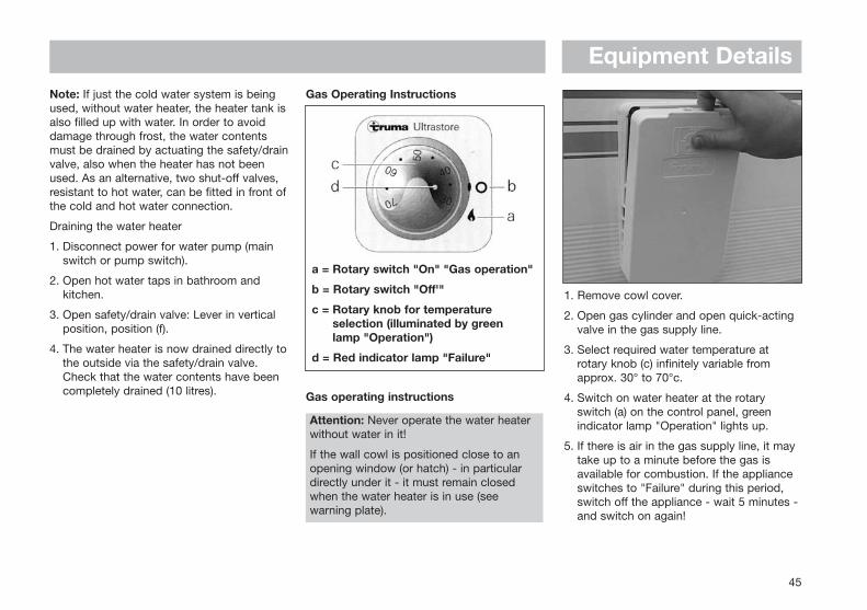
Gas Operating Instructions
Gas operating instructions
1. Remove cowl cover.
2. Open gas cylinder and open quick-actingvalve in the gas supply line.
3. Select required water temperature atrotary knob (c) infinitely variable fromapprox. 30° to 70°c.
4. Switch on water heater at the rotaryswitch (a) on the control panel, greenindicator lamp "Operation" lights up.
5. If there is air in the gas supply line, it maytake up to a minute before the gas isavailable for combustion. If the applianceswitches to "Failure" during this period,switch off the appliance - wait 5 minutes -and switch on again!
Equipment DetailsNote: If just the cold water system is beingused, without water heater, the heater tank isalso filled up with water. In order to avoiddamage through frost, the water contentsmust be drained by actuating the safety/drainvalve, also when the heater has not beenused. As an alternative, two shut-off valves,resistant to hot water, can be fitted in front ofthe cold and hot water connection.
Draining the water heater
1. Disconnect power for water pump (mainswitch or pump switch).
2. Open hot water taps in bathroom andkitchen.
3. Open safety/drain valve: Lever in verticalposition, position (f).
4. The water heater is now drained directly tothe outside via the safety/drain valve.Check that the water contents have beencompletely drained (10 litres).
45
a = Rotary switch "On" "Gas operation"
b = Rotary switch "Off'"
c = Rotary knob for temperatureselection (illuminated by green lamp "Operation")
d = Red indicator lamp "Failure"
Attention: Never operate the water heaterwithout water in it!
If the wall cowl is positioned close to anopening window (or hatch) - in particulardirectly under it - it must remain closedwhen the water heater is in use (seewarning plate).
46
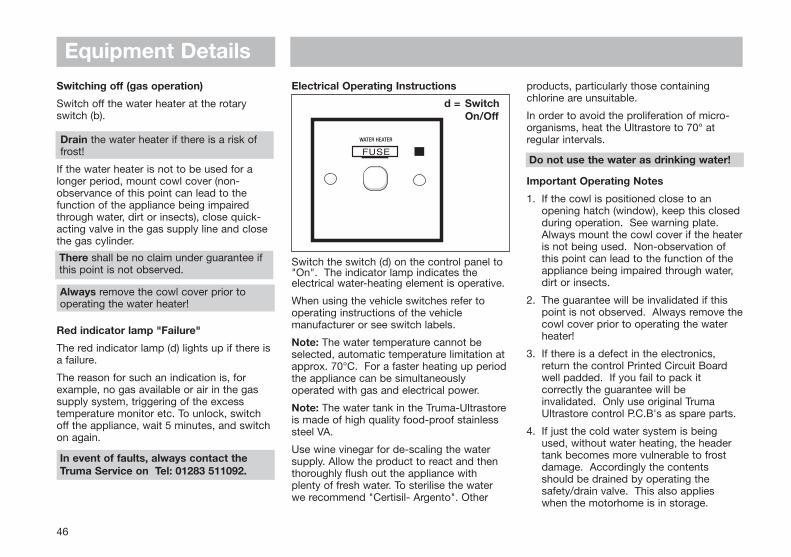
Switching off (gas operation)
Switch off the water heater at the rotaryswitch (b).
If the water heater is not to be used for alonger period, mount cowl cover (non-observance of this point can lead to thefunction of the appliance being impairedthrough water, dirt or insects), close quick-acting valve in the gas supply line and closethe gas cylinder.
Red indicator lamp "Failure"
The red indicator lamp (d) lights up if there isa failure.
The reason for such an indication is, forexample, no gas available or air in the gassupply system, triggering of the excesstemperature monitor etc. To unlock, switchoff the appliance, wait 5 minutes, and switchon again.
Electrical Operating Instructions
Switch the switch (d) on the control panel to"On". The indicator lamp indicates theelectrical water-heating element is operative.
When using the vehicle switches refer tooperating instructions of the vehiclemanufacturer or see switch labels.
Note: The water temperature cannot beselected, automatic temperature limitation atapprox. 70°C. For a faster heating up periodthe appliance can be simultaneouslyoperated with gas and electrical power.
Note: The water tank in the Truma-Ultrastoreis made of high quality food-proof stainlesssteel VA.
Use wine vinegar for de-scaling the watersupply. Allow the product to react and thenthoroughly flush out the appliance withplenty of fresh water. To sterilise the waterwe recommend "Certisil- Argento". Other
products, particularly those containingchlorine are unsuitable.
In order to avoid the proliferation of micro-organisms, heat the Ultrastore to 70° atregular intervals.
Important Operating Notes
1. If the cowl is positioned close to an opening hatch (window), keep this closedduring operation. See warning plate. Always mount the cowl cover if the heateris not being used. Non-observation of this point can lead to the function of the appliance being impaired through water, dirt or insects.
2. The guarantee will be invalidated if this point is not observed. Always remove thecowl cover prior to operating the water heater!
3. If there is a defect in the electronics, return the control Printed Circuit Board well padded. If you fail to pack it correctly the guarantee will be invalidated. Only use original Truma Ultrastore control P.C.B's as spare parts.
4. If just the cold water system is being used, without water heating, the header tank becomes more vulnerable to frost damage. Accordingly the contents should be drained by operating the safety/drain valve. This also applies when the motorhome is in storage.
Equipment Details
7060
50 4030
trumaUltrastore
remove cowl cover before use
FUSE
WATER HEATER
d = Switch On/Off
Drain the water heater if there is a risk offrost!
There shall be no claim under guarantee ifthis point is not observed.
Always remove the cowl cover prior tooperating the water heater!
In event of faults, always contact theTruma Service on Tel: 01283 511092.
Do not use the water as drinking water!

Equipment Details
47
General Safety Notes
In the event of leaks in the gas system or ifthere is a smell of gas:
• Extinguish all naked flames
• Do not smoke
• Switch off the appliance and gas cylinder
• Open the windows
• Do not operate any electrical switches
• Have the entire system checked by an expert
1. Repair jobs are only to be carried out by an expert.
2. The following would invalidate the guarantee:a. Any alteration to the appliance
(including cowl)b. The use of non-Truma spare
parts/accessoriesc. Non observance of the operating
instructions.
3. The operating pressure for the gas supply is 30mbar (or 28mbar butane/37mbar propane) and must correspond to the operating pressure of the appliance (see name plate).
4. Do not operate the water heater when refuelling the vehicle and when in the garage.
5. During the initial operation of a brand newappliance (or after it has not been used for some time), a certain amount of
fumes, and a slight smell, may be noticed for a short time. Remedial action is to immediately run the heater at maximum output and to ensure adequate room ventilation.
6. If the burner makes an unusual noise or if the flame lifts off, it is likely that the regulator is faulty and it is essential to have it checked.
Technical Data
Water contents: 10 litres
Water pressure: up to max. 2.8 bar
Type of gas: Liquid Gas (propane or butane)
Operating Pressure: 30mbar (or 28mbar butane, 37mbar propane)
Rated thermal output: 1500W
Gas consumption: 120g/h
Heating time to approx. 70°C:Gas operation: approx. 35 minsElectrical operation: approx. 70 minsGas and electrical operation: approx. 20 mins
Power consumption 12VIgnition: 0.17AHeating Up: 0.08AStandby: 0.04A
Power consumption 230VHeating Up: (2A) 450WWeight (empty): 6.7Kg
REFRIGERATORSBefore using your refrigerator for the firsttime, it is advisable to wash the interior andits accessories.
When using the refrigerator on gas ensurethat the gas isolation tap is fully open byturning the knob to the vertical position. Thetap is located inside the sink unit at floorheight. When travelling the fridge can only beoperated in the 12V mode.
Note: Before operating the refrigerator on12V, it should be pre-cooled, together withits contents, by running it on gas or 230Vfor a few hours before changing over to 12V for your journey.
The current drain is approximately 7A to 14A(model specific) and power is only availablewhen the ignition circuit is switched on. Onsite, only the mains electric or gas modesshould be used.
The refrigerator can run on either 230V, 12Vor LP gas. Changing between these modesof operation is carried out by means of thecontrols on the control panel.
Caution: Only use one source of energy at a time.
After initial installation, servicing or changinggas cylinders etc., the gas lines may containsome air which should be allowed to escapeby briefly turning on the refrigerator or otherappliances. This will ensure that the flamelights immediately.
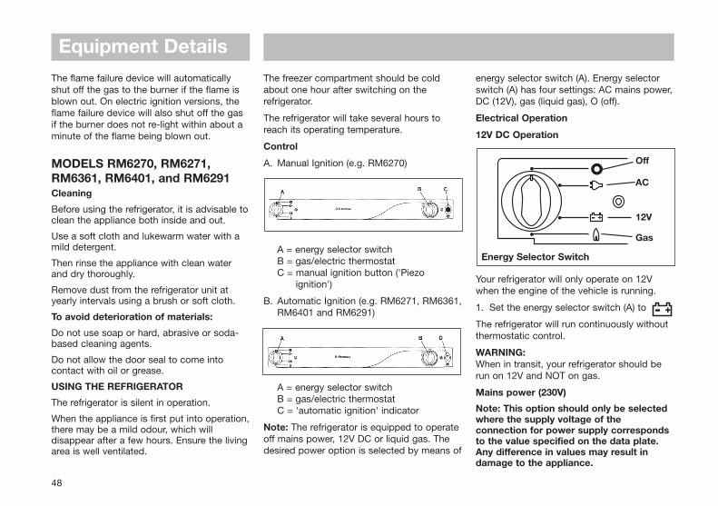
The freezer compartment should be coldabout one hour after switching on therefrigerator.
The refrigerator will take several hours toreach its operating temperature.
Control
A. Manual Ignition (e.g. RM6270)
A = energy selector switchB = gas/electric thermostatC = manual ignition button ('Piezo
ignition')
B. Automatic Ignition (e.g. RM6271, RM6361,RM6401 and RM6291)
A = energy selector switchB = gas/electric thermostatC = 'automatic ignition' indicator
Note: The refrigerator is equipped to operateoff mains power, 12V DC or liquid gas. Thedesired power option is selected by means of
Equipment Details
48
The flame failure device will automaticallyshut off the gas to the burner if the flame isblown out. On electric ignition versions, theflame failure device will also shut off the gasif the burner does not re-light within about aminute of the flame being blown out.
MODELS RM6270, RM6271,RM6361, RM6401, and RM6291Cleaning
Before using the refrigerator, it is advisable toclean the appliance both inside and out.
Use a soft cloth and lukewarm water with amild detergent.
Then rinse the appliance with clean waterand dry thoroughly.
Remove dust from the refrigerator unit atyearly intervals using a brush or soft cloth.
To avoid deterioration of materials:
Do not use soap or hard, abrasive or soda-based cleaning agents.
Do not allow the door seal to come intocontact with oil or grease.
USING THE REFRIGERATOR
The refrigerator is silent in operation.
When the appliance is first put into operation,there may be a mild odour, which willdisappear after a few hours. Ensure the livingarea is well ventilated.
energy selector switch (A). Energy selectorswitch (A) has four settings: AC mains power,DC (12V), gas (liquid gas), O (off).
Electrical Operation
12V DC Operation
Your refrigerator will only operate on 12Vwhen the engine of the vehicle is running.
1. Set the energy selector switch (A) to
The refrigerator will run continuously withoutthermostatic control.
WARNING:When in transit, your refrigerator should berun on 12V and NOT on gas.
Mains power (230V)
Note: This option should only be selectedwhere the supply voltage of theconnection for power supply correspondsto the value specified on the data plate.Any difference in values may result indamage to the appliance.
- +
Off
AC
12V
Gas
Energy Selector Switch
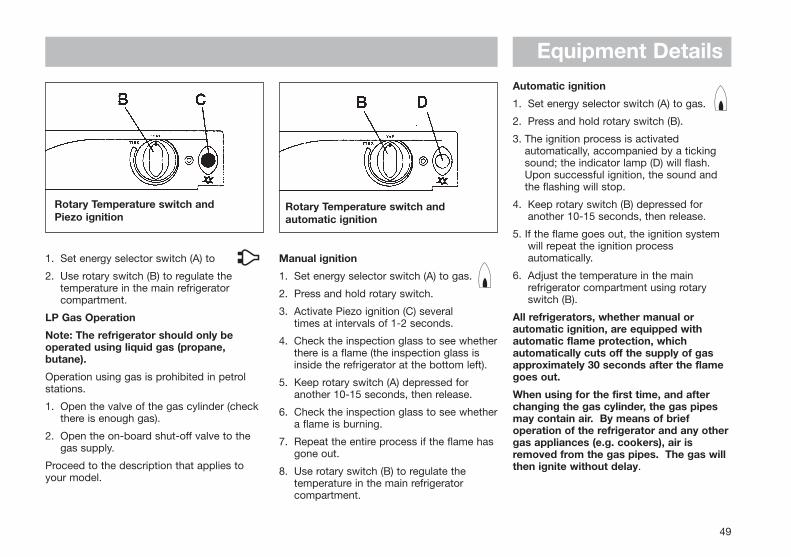
Equipment Details
49
1. Set energy selector switch (A) to
2. Use rotary switch (B) to regulate thetemperature in the main refrigerator compartment.
LP Gas Operation
Note: The refrigerator should only beoperated using liquid gas (propane,butane).
Operation using gas is prohibited in petrolstations.
1. Open the valve of the gas cylinder (check there is enough gas).
2. Open the on-board shut-off valve to the gas supply.
Proceed to the description that applies toyour model.
Automatic ignition
1. Set energy selector switch (A) to gas.
2. Press and hold rotary switch (B).
3. The ignition process is activated automatically, accompanied by a tickingsound; the indicator lamp (D) will flash.Upon successful ignition, the sound andthe flashing will stop.
4. Keep rotary switch (B) depressed for another 10-15 seconds, then release.
5. If the flame goes out, the ignition system will repeat the ignition process automatically.
6. Adjust the temperature in the main refrigerator compartment using rotary switch (B).
All refrigerators, whether manual orautomatic ignition, are equipped withautomatic flame protection, whichautomatically cuts off the supply of gasapproximately 30 seconds after the flamegoes out.
When using for the first time, and afterchanging the gas cylinder, the gas pipesmay contain air. By means of briefoperation of the refrigerator and any othergas appliances (e.g. cookers), air isremoved from the gas pipes. The gas willthen ignite without delay.
Manual ignition
1. Set energy selector switch (A) to gas.
2. Press and hold rotary switch.
3. Activate Piezo ignition (C) several times at intervals of 1-2 seconds.
4. Check the inspection glass to see whetherthere is a flame (the inspection glass is inside the refrigerator at the bottom left).
5. Keep rotary switch (A) depressed for another 10-15 seconds, then release.
6. Check the inspection glass to see whethera flame is burning.
7. Repeat the entire process if the flame has gone out.
8. Use rotary switch (B) to regulate the temperature in the main refrigerator compartment.
Rotary Temperature switch and Piezo ignition
Rotary Temperature switch andautomatic ignition
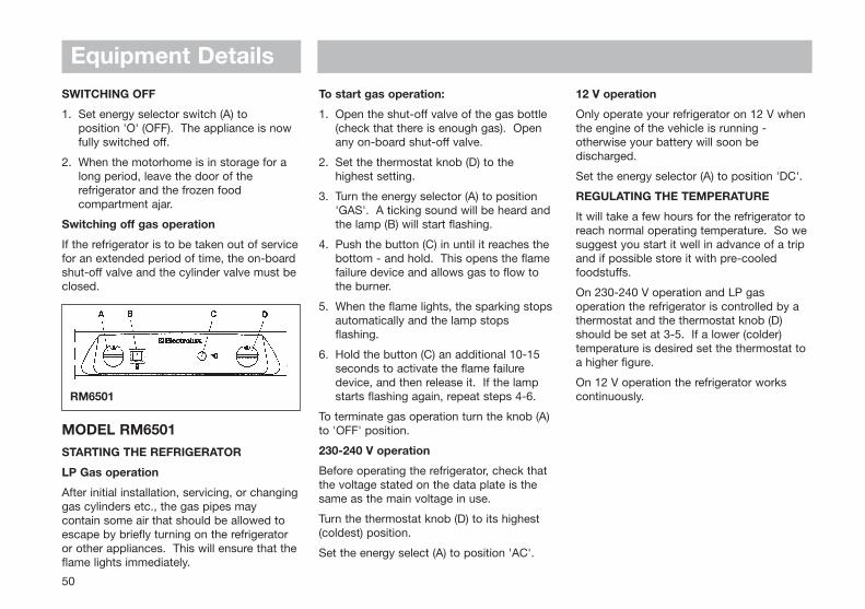
Equipment DetailsSWITCHING OFF
1. Set energy selector switch (A) to position 'O' (OFF). The appliance is now fully switched off.
2. When the motorhome is in storage for a long period, leave the door of the refrigerator and the frozen food compartment ajar.
Switching off gas operation
If the refrigerator is to be taken out of servicefor an extended period of time, the on-boardshut-off valve and the cylinder valve must beclosed.
MODEL RM6501STARTING THE REFRIGERATOR
LP Gas operation
After initial installation, servicing, or changinggas cylinders etc., the gas pipes maycontain some air that should be allowed toescape by briefly turning on the refrigeratoror other appliances. This will ensure that theflame lights immediately.
To start gas operation:
1. Open the shut-off valve of the gas bottle (check that there is enough gas). Open any on-board shut-off valve.
2. Set the thermostat knob (D) to the highest setting.
3. Turn the energy selector (A) to position 'GAS'. A ticking sound will be heard and the lamp (B) will start flashing.
4. Push the button (C) in until it reaches the bottom - and hold. This opens the flame failure device and allows gas to flow to the burner.
5. When the flame lights, the sparking stopsautomatically and the lamp stops flashing.
6. Hold the button (C) an additional 10-15 seconds to activate the flame failure device, and then release it. If the lamp starts flashing again, repeat steps 4-6.
To terminate gas operation turn the knob (A)to 'OFF' position.
230-240 V operation
Before operating the refrigerator, check thatthe voltage stated on the data plate is thesame as the main voltage in use.
Turn the thermostat knob (D) to its highest(coldest) position.
Set the energy select (A) to position 'AC'.
12 V operation
Only operate your refrigerator on 12 V whenthe engine of the vehicle is running -otherwise your battery will soon bedischarged.
Set the energy selector (A) to position 'DC'.
REGULATING THE TEMPERATURE
It will take a few hours for the refrigerator toreach normal operating temperature. So wesuggest you start it well in advance of a tripand if possible store it with pre-cooledfoodstuffs.
On 230-240 V operation and LP gasoperation the refrigerator is controlled by athermostat and the thermostat knob (D)should be set at 3-5. If a lower (colder)temperature is desired set the thermostat toa higher figure.
On 12 V operation the refrigerator workscontinuously.
50
RM6501
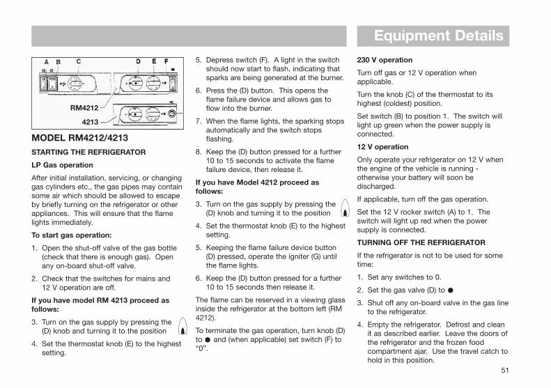
Equipment Details
MODEL RM4212/4213STARTING THE REFRIGERATOR
LP Gas operation
After initial installation, servicing, or changinggas cylinders etc., the gas pipes may containsome air which should be allowed to escapeby briefly turning on the refrigerator or otherappliances. This will ensure that the flamelights immediately.
To start gas operation:
1. Open the shut-off valve of the gas bottle(check that there is enough gas). Openany on-board shut-off valve.
2. Check that the switches for mains and 12 V operation are off.
If you have model RM 4213 proceed asfollows:
3. Turn on the gas supply by pressing the(D) knob and turning it to the position
4. Set the thermostat knob (E) to the highestsetting.
5. Depress switch (F). A light in the switchshould now start to flash, indicating thatsparks are being generated at the burner.
6. Press the (D) button. This opens theflame failure device and allows gas toflow into the burner.
7. When the flame lights, the sparking stopsautomatically and the switch stopsflashing.
8. Keep the (D) button pressed for a further10 to 15 seconds to activate the flamefailure device, then release it.
If you have Model 4212 proceed asfollows:
3. Turn on the gas supply by pressing the(D) knob and turning it to the position
4. Set the thermostat knob (E) to the highestsetting.
5. Keeping the flame failure device button(D) pressed, operate the igniter (G) untilthe flame lights.
6. Keep the (D) button pressed for a further10 to 15 seconds then release it.
The flame can be reserved in a viewing glassinside the refrigerator at the bottom left (RM4212).
To terminate the gas operation, turn knob (D)to and (when applicable) set switch (F) to“0”.
230 V operation
Turn off gas or 12 V operation whenapplicable.
Turn the knob (C) of the thermostat to itshighest (coldest) position.
Set switch (B) to position 1. The switch willlight up green when the power supply isconnected.
12 V operation
Only operate your refrigerator on 12 V whenthe engine of the vehicle is running -otherwise your battery will soon bedischarged.
If applicable, turn off the gas operation.
Set the 12 V rocker switch (A) to 1. Theswitch will light up red when the powersupply is connected.
TURNING OFF THE REFRIGERATOR
If the refrigerator is not to be used for sometime:
1. Set any switches to 0.
2. Set the gas valve (D) to
3. Shut off any on-board valve in the gas lineto the refrigerator.
4. Empty the refrigerator. Defrost and cleanit as described earlier. Leave the doors ofthe refrigerator and the frozen foodcompartment ajar. Use the travel catch tohold in this position.
51
RM4212
4213
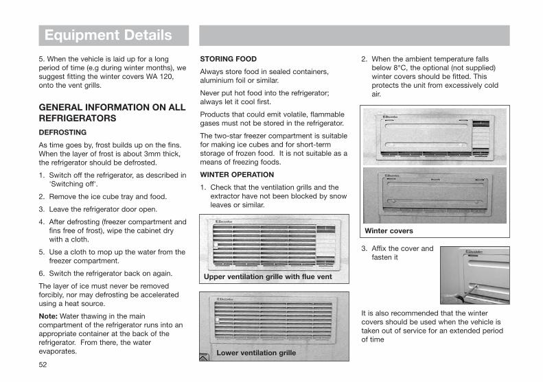
52
5. When the vehicle is laid up for a longperiod of time (e.g during winter months), wesuggest fitting the winter covers WA 120,onto the vent grills.
GENERAL INFORMATION ON ALLREFRIGERATORSDEFROSTING
As time goes by, frost builds up on the fins.When the layer of frost is about 3mm thick,the refrigerator should be defrosted.
1. Switch off the refrigerator, as described in'Switching off'.
2. Remove the ice cube tray and food.
3. Leave the refrigerator door open.
4. After defrosting (freezer compartment andfins free of frost), wipe the cabinet dry with a cloth.
5. Use a cloth to mop up the water from thefreezer compartment.
6. Switch the refrigerator back on again.
The layer of ice must never be removedforcibly, nor may defrosting be acceleratedusing a heat source.
Note: Water thawing in the maincompartment of the refrigerator runs into anappropriate container at the back of therefrigerator. From there, the waterevaporates.
STORING FOOD
Always store food in sealed containers,aluminium foil or similar.
Never put hot food into the refrigerator;always let it cool first.
Products that could emit volatile, flammablegases must not be stored in the refrigerator.
The two-star freezer compartment is suitablefor making ice cubes and for short-termstorage of frozen food. It is not suitable as ameans of freezing foods.
WINTER OPERATION
1. Check that the ventilation grills and the extractor have not been blocked by snowleaves or similar.
2. When the ambient temperature falls below 8°C, the optional (not supplied) winter covers should be fitted. This protects the unit from excessively cold air.
3. Affix the cover and fasten it
It is also recommended that the wintercovers should be used when the vehicle istaken out of service for an extended periodof time
Lower ventilation grille
Upper ventilation grille with flue vent
Winter covers
Equipment Details
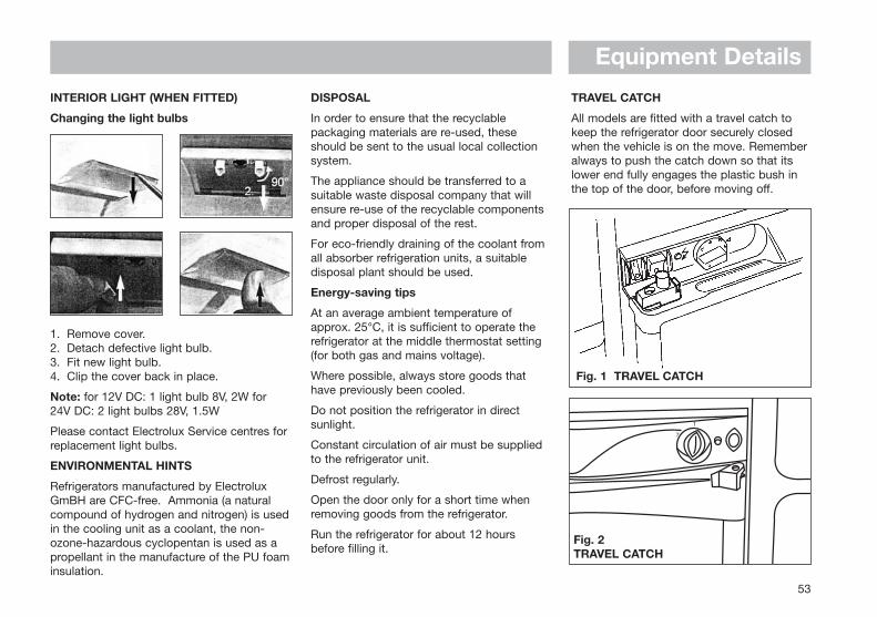
53
INTERIOR LIGHT (WHEN FITTED)
Changing the light bulbs
1. Remove cover.2. Detach defective light bulb.3. Fit new light bulb.4. Clip the cover back in place.
Note: for 12V DC: 1 light bulb 8V, 2W for24V DC: 2 light bulbs 28V, 1.5W
Please contact Electrolux Service centres forreplacement light bulbs.
ENVIRONMENTAL HINTS
Refrigerators manufactured by ElectroluxGmBH are CFC-free. Ammonia (a naturalcompound of hydrogen and nitrogen) is usedin the cooling unit as a coolant, the non-ozone-hazardous cyclopentan is used as apropellant in the manufacture of the PU foaminsulation.
DISPOSAL
In order to ensure that the recyclablepackaging materials are re-used, theseshould be sent to the usual local collectionsystem.
The appliance should be transferred to asuitable waste disposal company that willensure re-use of the recyclable componentsand proper disposal of the rest.
For eco-friendly draining of the coolant fromall absorber refrigeration units, a suitabledisposal plant should be used.
Energy-saving tips
At an average ambient temperature ofapprox. 25°C, it is sufficient to operate therefrigerator at the middle thermostat setting(for both gas and mains voltage).
Where possible, always store goods thathave previously been cooled.
Do not position the refrigerator in directsunlight.
Constant circulation of air must be suppliedto the refrigerator unit.
Defrost regularly.
Open the door only for a short time whenremoving goods from the refrigerator.
Run the refrigerator for about 12 hoursbefore filling it.
TRAVEL CATCH
All models are fitted with a travel catch tokeep the refrigerator door securely closedwhen the vehicle is on the move. Rememberalways to push the catch down so that itslower end fully engages the plastic bush inthe top of the door, before moving off.
Fig. 1 TRAVEL CATCH
Equipment Details
Fig. 2TRAVEL CATCH
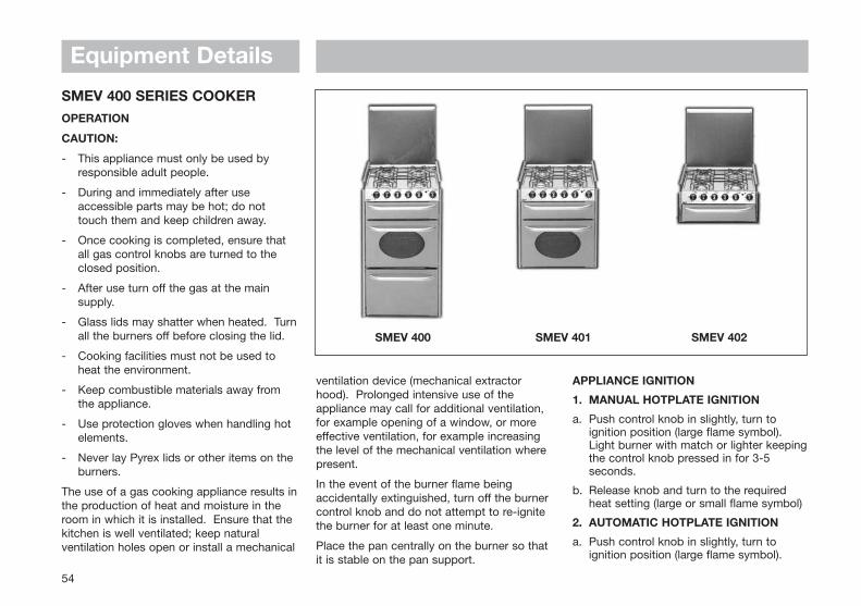
54
SMEV 400 SERIES COOKEROPERATION
CAUTION:
- This appliance must only be used by responsible adult people.
- During and immediately after use accessible parts may be hot; do not touch them and keep children away.
- Once cooking is completed, ensure that all gas control knobs are turned to the closed position.
- After use turn off the gas at the main supply.
- Glass lids may shatter when heated. Turnall the burners off before closing the lid.
- Cooking facilities must not be used to heat the environment.
- Keep combustible materials away from the appliance.
- Use protection gloves when handling hot elements.
- Never lay Pyrex lids or other items on the burners.
The use of a gas cooking appliance results inthe production of heat and moisture in theroom in which it is installed. Ensure that thekitchen is well ventilated; keep naturalventilation holes open or install a mechanical
Equipment Details
ventilation device (mechanical extractorhood). Prolonged intensive use of theappliance may call for additional ventilation,for example opening of a window, or moreeffective ventilation, for example increasingthe level of the mechanical ventilation wherepresent.
In the event of the burner flame beingaccidentally extinguished, turn off the burnercontrol knob and do not attempt to re-ignitethe burner for at least one minute.
Place the pan centrally on the burner so thatit is stable on the pan support.
APPLIANCE IGNITION
1. MANUAL HOTPLATE IGNITION
a. Push control knob in slightly, turn to ignition position (large flame symbol). Light burner with match or lighter keepingthe control knob pressed in for 3-5 seconds.
b. Release knob and turn to the required heat setting (large or small flame symbol)
2. AUTOMATIC HOTPLATE IGNITION
a. Push control knob in slightly, turn to ignition position (large flame symbol).
SMEV 400 SMEV 401 SMEV 402
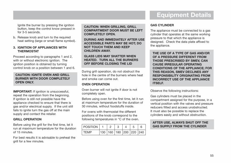
Equipment Details
55
Ignite the burner by pressing the ignition button, keep the control know pressed in for 3-5 seconds.
b. Release knob and turn to the required heat setting (large or small flame symbol).
3. IGNITION OF APPLIANCES WITH THERMOSTAT
Proceed according to paragraphs 1 and 2,with or without electronic ignition. Theignition position is obtained by turningcontrol knob on a position between 1 and 6.
CAUTION: IGNITE OVEN AND GRILL BURNER WITH DOOR COMPLETELY OPEN ONLY.
IMPORTANT: If ignition is unsuccessful,repeat the operation from the beginning. If ignition is still not possible have theappliance checked to ensure that there isgas and/or electrical supply. If the unit stillfails to ignite turn the gas off at the mainsupply and contact the retailer.
GRILL OPERATION
Before using the grill for the first time, let itrun at maximum temperature for the durationof 15 minutes.
For best results it is advisable to preheat thegrill for a few minutes.
CAUTION: WHEN GRILLING, GRILL COMPARTMENT DOOR MUST BE LEFT COMPLETELY OPEN.
DURING AND IMMEDIATELY AFTER USEACCESSIBLE PARTS MAY BE HOT; DO NOT TOUCH THEM AND KEEP CHILDREN AWAY.
GLASS LIDS MAY SHATTER WHEN HEATED. TURN ALL THE BURNERS OFF BEFORE CLOSING THE LID
During grill operation, do not obstruct thehole in the centre of the burners where heatand smoke can come out.
OVEN OPERATION
Oven burner will not ignite if door is notcompletely open.
Before using oven for the first time, let it runat maximum temperature for the duration of30 minutes, without foodstuffs inside.
For ovens with thermostat the differentpositions of the knob correspond to thefollowing temperatures in °C of the oven.
POSITION 1 2 3 4 5 6
TEMP 130 160 180 200 220 240
GAS CYLINDER
The appliance must be connected to a gascylinder that operates at the same workingpressure to that which the appliance isdesigned. Check the data plate affixed tothe appliance.
THE USE OF A TYPE OF GAS AND/OR OF A PRESSURE DIFFERENT FROM THOSE PRESCRIBED BY SMEV, CAN CAUSE IRREGULAR OPERATING CONDITIONS OF THE APPLIANCE; FOR THIS REASON, SMEV DECLINES ANY RESPONSIBILITY ORIGINATING FROM INCORRECT USE OF THE APPLIANCE ITSELF.
Observe the following instructions:
Gas cylinders must be placed in thecompartment assigned for the purpose, in avertical position with the valves and pressurereducers fitted and access unobstructed. It must also be possible to replace thecylinders easily and without obstruction.
AFTER USE, ALWAYS SHUT OFF THE GAS SUPPLY FROM THE CYLINDER
d. Close cylinder or tank supply valves. Donot turn on valves until leak has been corrected.
e. Immediately call an authorisedserviceman.
CLEANING AND MAINTENANCE
Turn off the appliance and allow to coolbefore cleaning. Cold water or a damp clothmay damage hot surfaces.
Do not use abrasive, corrosive, chloride-based products or steel pads. Do not leaveacidic or alkaline substances e.g. vinegar,salt, lemon juice etc, on the appliancesurfaces.
Stainless steel surfaces and enamelled partsshould only be washed with soapy water orneutral detergent, rinsed and dried. Only useclean sponges or cloths.
Equipment Details
ATTENTION! When replacing the gas cylinder,the following precautions must be taken:
a. Close tapes to the appliance (pos.l );
b. Make sure there are no flames or fires lit in the proximity;
c. Close valve of cylinder to be replaced;
d. Unscrew regulator from empty cylinder and remove from its storage compartment. Reverse procedure for replacement. Check possible gas leaks by means of a soapy solution as described above.
e. Ignite burners and check correct operation. Contact an authorised technician if the unit shows signs of failure.
GAS LEAKS
We recommend using an approved electronicdetector for gas leaks.
If you smell gas:
a. Open window and immediately get all people out of the motorhome.
b. Do not touch electrical switches, light matches or do anything that could ignite gas.
c. Extinguish any open flame.
56
STOVES HOBS, GRILLS ANDOVENSBURNER IGNITION
The hotplate lid must be open for thehotplate, grill or oven burners to ignite.
The ignition should not be operated for morethan 15 seconds. If, after 15 seconds theburner has not lit, stop operating the ignition,open the compartment door and wait at least1 minute before attempting to ignite theburner.
In the event of the burner flames beingaccidentally extinguished, turn off the burnercontrol and do not attempt to re-light theburner for at least 1 minute.
SPARE PARTS
When ordering spare parts, please give thefollowing information so the appliance can becorrectly identified:
1. The name of the appliance from the facia, and its colour.
2. The model number and the serial number of the appliance (from the data badge).
BE SAFE - NOT SORRY
Warning: Good ventilation is essential to thecontinuing safe operation of all gasappliances. Do not allow any ventilationopenings to become accidentally ordeliberately blocked.
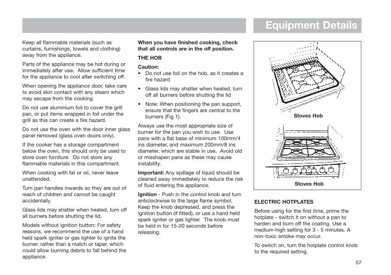
Equipment Details
57
Keep all flammable materials (such ascurtains, furnishings, towels and clothing)away from the appliance.
Parts of the appliance may be hot during orimmediately after use. Allow sufficient timefor the appliance to cool after switching off.
When opening the appliance door, take careto avoid skin contact with any steam whichmay escape from the cooking.
Do not use aluminium foil to cover the grillpan, or put items wrapped in foil under thegrill as this can create a fire hazard.
Do not use the oven with the door inner glasspanel removed (glass oven doors only).
If the cooker has a storage compartmentbelow the oven, this should only be used tostore oven furniture. Do not store anyflammable materials in this compartment.
When cooking with fat or oil, never leaveunattended.
Turn pan handles inwards so they are out ofreach of children and cannot be caughtaccidentally.
Glass lids may shatter when heated, turn offall burners before shutting the lid.
Models without ignition button: For safetyreasons, we recommend the use of a handheld spark igniter or gas lighter to ignite theburner, rather than a match or taper, whichcould allow burning debris to fall behind theappliance.
When you have finished cooking, checkthat all controls are in the off position.
THE HOB
Caution:• Do not use foil on the hob, as it creates a
fire hazard
• Glass lids may shatter when heated, turn off all burners before shutting the lid
• Note: When positioning the pan support, ensure that the fingers are central to the burners (Fig 1).
Always use the most appropriate size ofburner for the pan you wish to use. Usepans with a flat base of minimum 100mm/4ins diameter, and maximum 200mm/8 insdiameter, which are stable in use. Avoid oldor misshapen pans as these may causeinstability.
Important: Any spillage of liquid should becleaned away immediately to reduce the riskof fluid entering the appliance.
Ignition - Push in the control knob and turnanticlockwise to the large flame symbol.Keep the knob depressed, and press theignition button (if fitted), or use a hand heldspark igniter or gas lighter. The knob mustbe held in for 15-20 seconds beforereleasing.
ELECTRIC HOTPLATES
Before using for the first time, prime thehotplate - switch it on without a pan toharden and burn off the coating. Use amedium-high setting for 3 - 5 minutes. Anon-toxic smoke may occur.
To switch on, turn the hotplate control knobto the required setting.
Stoves Hob
Stoves Hob
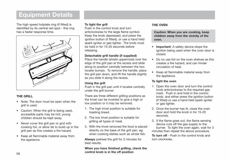
The high speed hotplate ring (if fitted) isidentified by its central red spot - this ringhas a faster response time.
THE GRILL
• Note: The door must be open when the grill is used.
• Caution: When the grill is being used, accessible parts may be hot; young children should be kept away.
• Never cover the grill pan or grid with cooking foil, or allow fat to build up in thegrill pan as this creates a fire hazard.
• Keep all flammable material away fromthe appliance.
To light the grillPush in the control knob and turnanticlockwise to the large flame symbol.Keep the knob depressed, and press theignition button (if fitted), or use a hand heldspark igniter or gas lighter. The knob mustbe held in for 15-20 seconds beforereleasing.
Detachable grill handle (if supplied)Place the handle (shield uppermost) over theedge of the grill pan at the recess and slidealong to position centrally between the twolocater bumps. To remove the handle, placethe grill pan down, and lift the handle slightlyas you slide it along the recess.
Using the grillPush in the grill pan until it locates centrallyunder the grill burner
There are three different grilling positions asthe trivet can be inverted to give a high orlow position or it may be removed.
1. The high trivet position is suitable for toasting bread.
2. The low trivet position is suitable for grilling all types of meat.
3. With the trivet removed the food is placeddirectly on the base of the grill pan, eg; when cooking dishes such as whole fish.
Always preheat the grill for 3 minutes forbest results.
When you have finished grilling, check thecontrol knob is in the off position
Equipment Details
58
THE OVEN
Caution: When you are cooking, keep children away from the vicinity of the oven.
• Important: A safety device stops the ignition being used when the oven door is closed.
• Do no use foil on the oven shelves as this creates a fire hazard, and can hinder circulation of heat.
• Keep all flammable material away from the appliance.
To light the oven
1. Open the oven door and turn the control knob anticlockwise to the required gas mark. Push in and hold in the control knob, and either press the ignition button (if fitted) or use a hand held spark igniter or gas lighter.
2. Once the burner has lit, close the oven door and hold the knob in for 15-20 seconds.
3. If the flame goes out, the flame sensing device cuts off the gas supply to the burner. To light the oven again, wait for 3
minutes then repeat the above procedure.To turn off - Push in the control knob andturn clockwise.
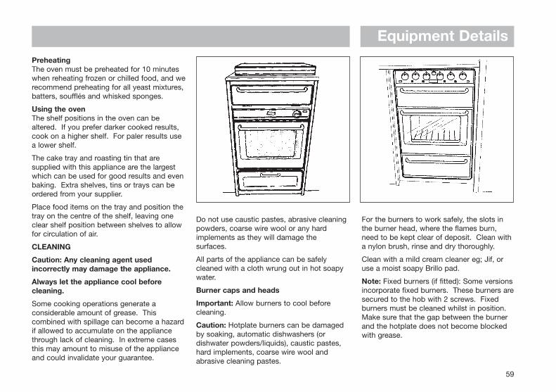
Equipment Details
59
PreheatingThe oven must be preheated for 10 minuteswhen reheating frozen or chilled food, and werecommend preheating for all yeast mixtures,batters, soufflés and whisked sponges.
Using the ovenThe shelf positions in the oven can bealtered. If you prefer darker cooked results,cook on a higher shelf. For paler results usea lower shelf.
The cake tray and roasting tin that aresupplied with this appliance are the largestwhich can be used for good results and evenbaking. Extra shelves, tins or trays can beordered from your supplier.
Place food items on the tray and position thetray on the centre of the shelf, leaving oneclear shelf position between shelves to allowfor circulation of air.
CLEANING
Caution: Any cleaning agent usedincorrectly may damage the appliance.
Always let the appliance cool beforecleaning.
Some cooking operations generate aconsiderable amount of grease. Thiscombined with spillage can become a hazardif allowed to accumulate on the appliancethrough lack of cleaning. In extreme casesthis may amount to misuse of the applianceand could invalidate your guarantee.
Do not use caustic pastes, abrasive cleaningpowders, coarse wire wool or any hardimplements as they will damage thesurfaces.
All parts of the appliance can be safelycleaned with a cloth wrung out in hot soapywater.
Burner caps and heads
Important: Allow burners to cool beforecleaning.
Caution: Hotplate burners can be damagedby soaking, automatic dishwashers (ordishwater powders/liquids), caustic pastes,hard implements, coarse wire wool andabrasive cleaning pastes.
For the burners to work safely, the slots inthe burner head, where the flames burn,need to be kept clear of deposit. Clean witha nylon brush, rinse and dry thoroughly.
Clean with a mild cream cleaner eg; Jif, oruse a moist soapy Brillo pad.
Note: Fixed burners (if fitted): Some versionsincorporate fixed burners. These burners aresecured to the hob with 2 screws. Fixedburners must be cleaned whilst in position.Make sure that the gap between the burnerand the hotplate does not become blockedwith grease.
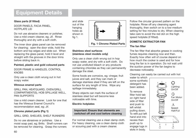
Glass parts (if fitted)
DOOR PANELS, FACIA PANEL, HOTPLATE LID
Do not use abrasive cleaners or polishes.Use a mild cream cleaner, eg; Jif. Rinsethoroughly and dry with a soft cloth.
The inner door glass panel can be removedfor cleaning; open the door wide, hold thebottom and top edges and slide out. Whenreplacing the glass panel, hold it level andstraight with the grooves in the door trimsbefore sliding back in.
Painted, plastic and gold coloured parts
DOOR FRAME & HANDLES, CONTROLKNOBS
Only use a clean cloth wrung out in hotsoapy water.
Vitreous enamel parts
GRILL PAN, HEATGUARD, OVEN/GRILLCOMPARTMENT(S), HOB SPILLAGE WELL,PAN SUPPORTS
Use a mild cream cleaner. Look for one thathas the Vitreous Enamel Council'srecommendation seal, eg; Jif.
Chrome plated parts (Fig 1)
GRILL GRID, SHELVES, SHELF RUNNERS
Do no use abrasives or polishes. Use amoist soap pad, eg; Brillo. Shelf runners canbe removed for cleaning. Grasp the runners
and slide out of thehangingholes asshown in fig 1.
Stainless steel surfaces (stainless steel models only)
Only use a clean cloth wrung out in hopsoapy water, and dry with a soft cloth. Donot use undiluted bleach or any productscontaining chlorides as they can permanentlydamage the steel.
Some foods are corrosive, eg; vinegar, fruitjuices and salt, and they can mark ordamage stainless steel if they are left on thesurface for any length of time. Wipe anyspillage immediately.
Sharp objects can mark the surface ofstainless steel but will become lessnoticeable with time.
Electric hotplates
Important: Ensure that elements are switched off and cool before cleaning
For normal cleaning use a clean damp cloth.For heavy cleaning, use a clean damp clothor scouring pad with a cream cleaner.
Follow the circular grooved pattern on thehotplate. Rinse off any cleansing agentthoroughly, then switch on to a low-mediumsetting for few minutes to dry. When cleaningtake care to avoid the red dot on the highspeed hotplate (if fitted).
DOMETIC EXTRACTOR FAN
The fan filter
The fan filter that absorbs grease in cookingfumes requires cleaning now and then.Exactly how often will of course depend onhow much the cooker is used and for howlong the fan is in operation. Do not wait untilthe suction power of the fan begins todecrease noticeably.
Cleaning can easily be carried out with hotwater to whichsome syntheticdetergent hasbeen added.
To removefilter hold tabon right handside of filterand push toleft whilstpulling down.To refit put lefthand end intorecess thenpush up toengage lugs inslots in body.
Equipment Details
60
Fig. 1 Chrome Plated Parts
Lighting:On/Off
Fan Motor:On/Off
Speed:Half/Full
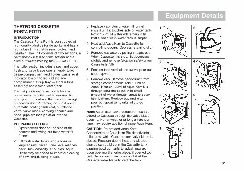
Equipment Details
61
THETFORD CASSETTE PORTA POTTIINTRODUCTIONThe Cassette Porta Potti is constructed ofhigh quality plastics for durability and has ahigh gloss finish that is easy to clean andmaintain. The unit consists of two sections, apermanently installed toilet system and aslide out waste holding tank — CASSETTE.
The toilet section includes a seat and cover,flush and valve blade opener knob, toilettissue compartment and holder, waste levelindicator, built-in toilet fluid storagecompartment, a drip tray — a drain tubeassembly and a fresh water tank.
The unique Cassette section is locatedunderneath the toilet and is removed foremptying from outside the caravan throughan access door. A rotating pour-out spout,automatic holding tank vent, air releasevalve, valve blade, carrying handles andhand grips are incorporated into theCassette.
PREPARING FOR USE1. Open access door on the side of the
caravan and swing out fresh water fill funnel.
2. Fill fresh water tank using a hose or jerrycan until water funnel level reaches neck. Tank capacity is 15 litres. Aqua Rinse may be added to improve cleaning of bowl and flushing of unit.
3. Replace cap. Swing water fill funnel inward until it touches side of water tank. Note: 150ml of water will remain in fill bottle when fresh water tank is empty.
4. Next add Aqua Kem to Cassette for controlling odours. Depress retaining clip.
5. Remove cassette by pulling straight out. When Cassette hits stop, tilt downward slightly and remove (stop for safety when Cassette is full).
6. Position tank vertical and swivel pour out spout upward.
7. Remove cap. Remove deodourant from storage compartment. Add 100ml ofAqua Kem or 120ml of Aqua Kem Biothrough pour out spout. Add smallamount of water through spout to covertank bottom. Replace cap and returnpour out spout to its original storedposition.
Note: As an alternative deodourant can beadded to Cassette through the valve bladeopening. Hotter weather or longer retentiontime may require addition of more Aqua Kem.
CAUTION: Do not add Aqua KemConcentrate or Aqua Kem Bio directly intotoilet bowl while Cassette tank valve blade isclosed. Pressure due to heat and altitudechange can build up in the Cassette tankcausing bowl contents to splash upwardupon opening the valve blade, if opened toofast. Before each use, open and shut theCassette valve blade to vent the tank
1 2
3 4
5 6
7
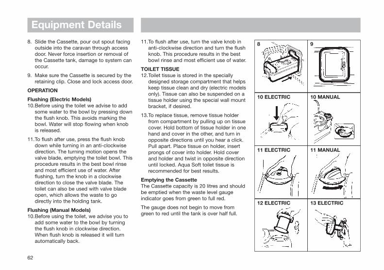
62
Equipment Details8. Slide the Cassette, pour out spout facing
outside into the caravan through access door. Never force insertion or removal of the Cassette tank, damage to system can occur.
9. Make sure the Cassette is secured by the retaining clip. Close and lock access door.
OPERATION
Flushing (Electric Models)10.Before using the toilet we advise to add
some water to the bowl by pressing downthe flush knob. This avoids marking the bowl. Water will stop flowing when knob is released.
11.To flush after use, press the flush knob down while turning in an anti-clockwise direction. The turning motion opens the valve blade, emptying the toilet bowl. Thisprocedure results in the best bowl rinse and most efficient use of water. After flushing, turn the knob in a clockwise direction to close the valve blade. The toilet can also be used with valve blade open, which allows the waste to go directly into the holding tank.
Flushing (Manual Models)10.Before using the toilet, we advise you to
add some water to the bowl by turning the flush knob in clockwise direction. When flush knob is released it will turn automatically back.
11.To flush after use, turn the valve knob in anti-clockwise direction and turn the flush knob. This procedure results in the best bowl rinse and most efficient use of water.
TOILET TISSUE12.Toilet tissue is stored in the specially
designed storage compartment that helpskeep tissue clean and dry (electric modelsonly). Tissue can also be suspended on a tissue holder using the special wall mountbracket, if desired.
13.To replace tissue, remove tissue holder from compartment by pulling up on tissue cover. Hold bottom of tissue holder in onehand and cover in the other, and turn in opposite directions until you hear a click. Pull apart. Place tissue on holder, insert prongs of cover into holder. Hold cover and holder and twist in opposite direction until locked. Aqua Soft toilet tissue is recommended for best results.
Emptying the CassetteThe Cassette capacity is 20 litres and shouldbe emptied when the waste level gaugeindicator goes from green to full red.
The gauge does not begin to move fromgreen to red until the tank is over half full.
8 9
10 ELECTRIC 10 MANUAL
11 ELECTRIC 11 MANUAL
12 ELECTRIC 13 ELECTRIC
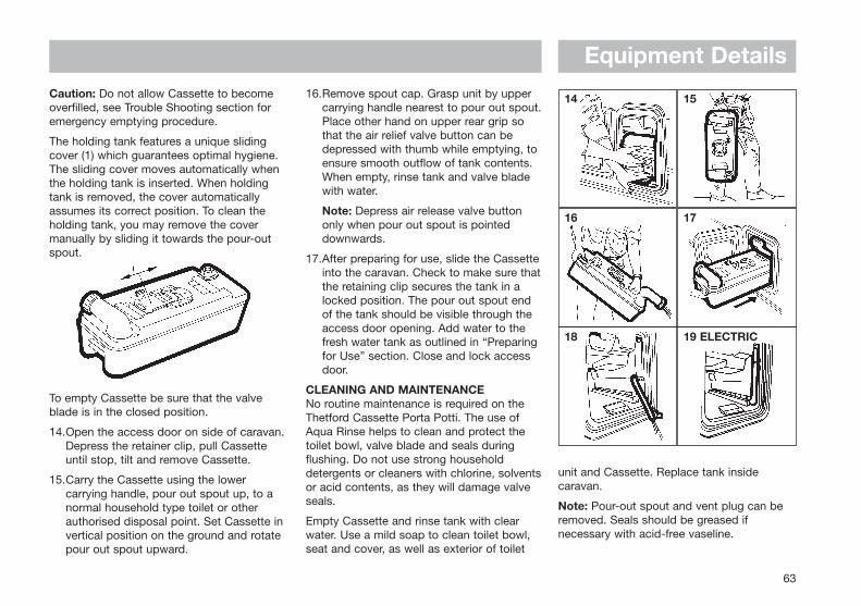
63
Equipment DetailsCaution: Do not allow Cassette to becomeoverfilled, see Trouble Shooting section foremergency emptying procedure.
The holding tank features a unique slidingcover (1) which guarantees optimal hygiene.The sliding cover moves automatically whenthe holding tank is inserted. When holdingtank is removed, the cover automaticallyassumes its correct position. To clean theholding tank, you may remove the covermanually by sliding it towards the pour-outspout.
To empty Cassette be sure that the valveblade is in the closed position.
14.Open the access door on side of caravan.Depress the retainer clip, pull Cassette until stop, tilt and remove Cassette.
15.Carry the Cassette using the lower carrying handle, pour out spout up, to a normal household type toilet or other authorised disposal point. Set Cassette invertical position on the ground and rotate pour out spout upward.
16.Remove spout cap. Grasp unit by upper carrying handle nearest to pour out spout.Place other hand on upper rear grip so that the air relief valve button can be depressed with thumb while emptying, to ensure smooth outflow of tank contents. When empty, rinse tank and valve blade with water.
Note: Depress air release valve button only when pour out spout is pointed downwards.
17.After preparing for use, slide the Cassetteinto the caravan. Check to make sure thatthe retaining clip secures the tank in a locked position. The pour out spout end of the tank should be visible through the access door opening. Add water to the fresh water tank as outlined in “Preparing for Use” section. Close and lock access door.
CLEANING AND MAINTENANCENo routine maintenance is required on theThetford Cassette Porta Potti. The use ofAqua Rinse helps to clean and protect thetoilet bowl, valve blade and seals duringflushing. Do not use strong householddetergents or cleaners with chlorine, solventsor acid contents, as they will damage valveseals.
Empty Cassette and rinse tank with clearwater. Use a mild soap to clean toilet bowl,seat and cover, as well as exterior of toilet
unit and Cassette. Replace tank insidecaravan.
Note: Pour-out spout and vent plug can beremoved. Seals should be greased ifnecessary with acid-free vaseline.
14 15
16 17
18 19 ELECTRIC
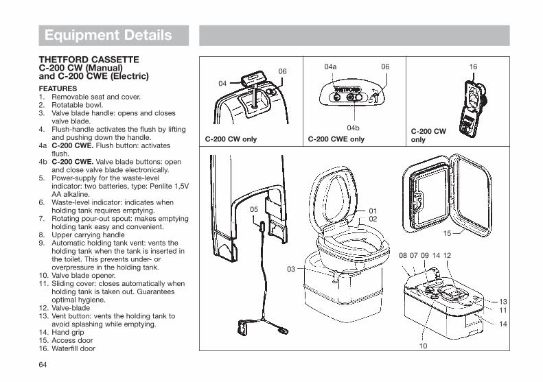
64
Equipment Details
C-200 CW only C-200 CWE onlyC-200 CWonly
05
04
0604a 06 16
04b
03
0102
08 07 09 14 12
1311
14
10
15
THETFORD CASSETTEC-200 CW (Manual)and C-200 CWE (Electric)FEATURES1. Removable seat and cover.2. Rotatable bowl.3. Valve blade handle: opens and closes
valve blade.4. Flush-handle activates the flush by lifting
and pushing down the handle.4a C-200 CWE. Flush button: activates
flush.4b C-200 CWE. Valve blade buttons: open
and close valve blade electronically.5. Power-supply for the waste-level
indicator: two batteries, type: Penlite 1,5VAA alkaline.
6. Waste-level indicator: indicates when holding tank requires emptying.
7. Rotating pour-out spout: makes emptyingholding tank easy and convenient.
8. Upper carrying handle9. Automatic holding tank vent: vents the
holding tank when the tank is inserted in the toilet. This prevents under- or overpressure in the holding tank.
10. Valve blade opener.11. Sliding cover: closes automatically when
holding tank is taken out. Guarantees optimal hygiene.
12. Valve-blade13. Vent button: vents the holding tank to
avoid splashing while emptying.14. Hand grip15. Access door16. Waterfill door
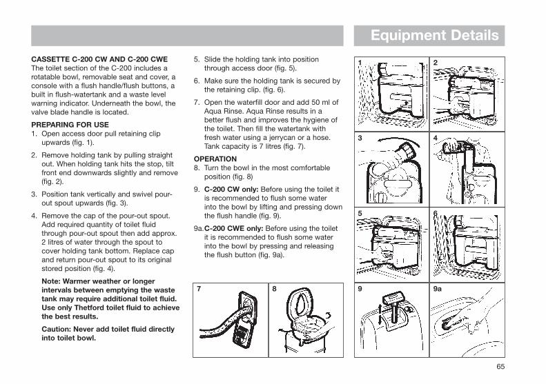
65
Equipment DetailsCASSETTE C-200 CW AND C-200 CWE The toilet section of the C-200 includes arotatable bowl, removable seat and cover, aconsole with a flush handle/flush buttons, abuilt in flush-watertank and a waste levelwarning indicator. Underneath the bowl, thevalve blade handle is located.
PREPARING FOR USE1. Open access door pull retaining clip
upwards (fig. 1).
2. Remove holding tank by pulling straight out. When holding tank hits the stop, tilt front end downwards slightly and remove (fig. 2).
3. Position tank vertically and swivel pour-out spout upwards (fig. 3).
4. Remove the cap of the pour-out spout. Add required quantity of toilet fluid through pour-out spout then add approx. 2 litres of water through the spout to cover holding tank bottom. Replace cap and return pour-out spout to its original stored position (fig. 4).
Note: Warmer weather or longer intervals between emptying the waste tank may require additional toilet fluid. Use only Thetford toilet fluid to achievethe best results.
Caution: Never add toilet fluid directly into toilet bowl.
5. Slide the holding tank into position through access door (fig. 5).
6. Make sure the holding tank is secured by the retaining clip. (fig. 6).
7. Open the waterfill door and add 50 ml of Aqua Rinse. Aqua Rinse results in a better flush and improves the hygiene of the toilet. Then fill the watertank with fresh water using a jerrycan or a hose. Tank capacity is 7 litres (fig. 7).
OPERATION8. Turn the bowl in the most comfortable
position (fig. 8)
9. C-200 CW only: Before using the toilet it is recommended to flush some water into the bowl by lifting and pressing downthe flush handle (fig. 9).
9a.C-200 CWE only: Before using the toilet it is recommended to flush some water into the bowl by pressing and releasing the flush button (fig. 9a).
87
1 2
3 4
5 6
9 9a
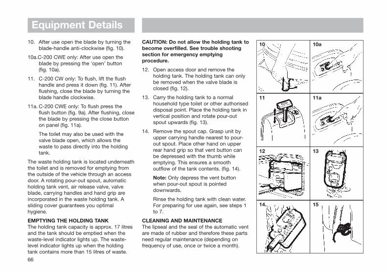
Equipment Details
66
10. After use open the blade by turning the blade-handle anti-clockwise (fig. 10).
10a.C-200 CWE only: After use open the blade by pressing the ‘open’ button (fig. 10a).
11. C-200 CW only: To flush, lift the flush handle and press it down (fig. 11). After flushing, close the blade by turning the blade handle clockwise.
11a. C-200 CWE only: To flush press the flush button (fig. 9a). After flushing, closethe blade by pressing the close button on panel (fig. 11a).
The toilet may also be used with the valve blade open, which allows the waste to pass directly into the holding tank.
The waste holding tank is located underneaththe toilet and is removed for emptying fromthe outside of the vehicle through an accessdoor. A rotating pour-out spout, automaticholding tank vent, air release valve, valveblade, carrying handles and hand grip areincorporated in the waste holding tank. Asliding cover guarantees you optimalhygiene.
EMPTYING THE HOLDING TANKThe holding tank capacity is approx. 17 litresand the tank should be emptied when thewaste-level indicator lights up. The waste-level indicator lights up when the holdingtank contains more than 15 litres of waste.
CAUTION: Do not allow the holding tank tobecome overfilled. See trouble shootingsection for emergency emptyingprocedure.
12. Open access door and remove the holding tank. The holding tank can only be removed when the valve blade is closed (fig. 12).
13. Carry the holding tank to a normal household type toilet or other authoriseddisposal point. Place the holding tank in vertical position and rotate pour-out spout upwards (fig. 13).
14. Remove the spout cap. Grasp unit by upper carrying handle nearest to pour-out spout. Place other hand on upper rear hand grip so that vent button can be depressed with the thumb while emptying. This ensures a smooth outflow of the tank contents. (fig. 14).
Note: Only depress the vent button when pour-out spout is pointed downwards.
Rinse the holding tank with clean water. For preparing for use again, see steps 1 to 7.
CLEANING AND MAINTENANCEThe lipseal and the seal of the automatic ventare made of rubber and therefore these partsneed regular maintenance (depending onfrequency of use, once or twice a month).
10 10a
11 11a
12 13
14 15
Equipment Details
67
Lipseal: Remove the sliding cover. Open thevalve-blade by turning the blade-openerknob anti-clockwise. Clean the seal withwater. Dry the seal and grease with siliconespray/oil or vegetable oil.
Seal of automatic vent: Turn the automaticvent 60° anti clockwise and remove gently.Clean the seal with water. Dry the seal andgrease with silicone spray/oil or vegetableoil.
To clean the holding tank, empty the tank,and rinse with clean water. Use a mild soapto clean toilet bowl, seat and cover, as wellas exterior of toilet unit and holding tank.
NOTE: Do not use strong householddetergents or cleaners that contain chlorine,solvents or acid contents.
WINTERING/STORAGEThe Thetford Cassette C-200 CW/CWE iseasily winterised for storage.
Empty remaining fresh water into the bowlby activating the flush handle up and down(C-200 CW) or by pressing the flush button(C-200 CWE).
Once pump has been cleared and water flowhas stopped completely, release into wastetank. Remove waste tank and emptycontents in normal way.
To evacuate any remaining water from thefresh water tank. place a containerunderneath the drainplug and removedrainplug.
When procedure has been completedreplace drainplug and waste holding tank(fig. 15). Clean the seals and grease themafter drying (see cleaning and maintenance).
Leave the blade of the holding tank open. Donot replace cap on the pour out spout, toventilate the holding tank. (Also grease theseal of the pour out spout cap.)
COLD WEATHER USEThe toilet can be used in cold weatherconditions provided that the toilet is inheated surroundings. If this is not the case,you can use a nontoxic antifreeze (propyleneglycol) or an antifreeze such as those used incar radiators. Add the antifreeze to the waterin the tank. Add the quantity specified in theinstructions, paying due regard to the safetyinstructions.
HIGH ALTITUDE AND WARM WEATHER USEPressure may build up in the holding tank ifthe tank is not inserted while driving at highaltitudes or in warm weather conditions. Theautomatic holding tank vent will vent thetank when there is over- or under-pressure.High temperatures may require additionalThetford toilet fluid.
THETFORD WARRANTY1. The Thetford Cassette is warranted for
one year from the date of purchase, please fill in and return the warranty card.
2. The warranty covers replacement of
defective or flawed parts and the inadequate performance of the toilet.
3. In case of a defect apply to an original dealer or Thetford Service Centre with proof of purchase.
4. Defects, which in our judgement occurred from misuse, negligence or accident, are not covered by the warranty. In addition, the warranty does not apply if the product is installed or handled improperlyor if other than the prescribed toilet fluids have been used or if the product has been altered in any way or has been repaired by unqualified persons, or if the serial number and/or date has been altered or removed.
5. Should the original buyer wish to return tous parts believed to be defective, the parts should be sent prepaid. If we find the parts defective and covered by warranty, they will be repaired and returned. If warranty does not apply or has expired, a nominal charge will be made. Any transport costs are for the account of the owner.
6. Before returning product or parts they should be properly cleaned, in order to carry out inspection and repair.
7. No other warranty is given and no personal representative is authorised to make any warranty other than that is contained herein.
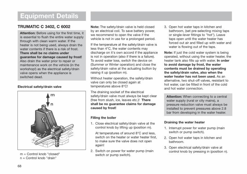
Note: The safety/drain valve is held closedby an electrical coil. To save battery power,we recommend to open the valve if thevehicle is not in use for a prolonged period.
If the temperature at the safely/drain valve isless than 4°C, the water contents maydischarge on it's own accord if the applianceis not in operation (also if there is a failure).To avoid water loss, switch the device on(Summer or Winter operation) and close thesafety/drain valve at the actuating button byraising it up (position m).
Without heater operation, the safety/drainvalve can only be closed again attemperatures above 8°C!
The draining socket of the electricalsafety/drain valve must always be kept clear(free from slush, ice, leaves etc.)! Thereshall be no guarantee claims for damagecaused by frost!
Filling the boiler
1. Close electrical safety/drain valve at thecontrol knob by lifting up (position m).
At temperatures of around 8°C and less,switch on the heater or water heater first,to make sure the valve does not openagain!
2. Switch on power for water pump (mainswitch or pump switch).
3. Open hot water taps in kitchen andbathroom, (set pre-selecting mixing tapsor single-lever fittings to "hot"). Leavetaps open until the water heater hasforced out air and filled up with water andwater is flowing out of the taps.
Note: If just the cold water system is beingoperated, without using the water heater, theheater tank also fills up with water. In orderto avoid damage by frost, the watercontents must be drained by operatingthe safety/drain valve, also when thewater heater has not been used. As analternative, two shut-off valves, resistant tohot water, can be fitted in front of the coldand hot water connection.
Attention: When connecting to a centralwater supply (rural or city mains), apressure reduction valve must always beinstalled to prevent pressures above 2.8bar from developing in the water heater.
Draining the water heater
1. Interrupt power for water pump (mainswitch or pump switch).
2. Open hot water taps in kitchen andbathroom.
3. Open electrical safety/drain valve atcontrol knob by pressing in (position n).
68
Equipment DetailsTRUMATIC C 3402, C 6002
Attention: Before using for the first time, itis essential to flush the entire water supplythrough with clean warm water. If the heater is not being used, always drain thewater contents if there is a risk of frost.There shall be no claims underguarantee for damage caused by frost!Also drain the water prior to repair ormaintenance work on the vehicle (in theworkshop!) as the electrical safety/drainvalve opens when the appliance is switched dead.
Electrical safety/drain valve
m = Control knob "closed"n = Control knob "drain"
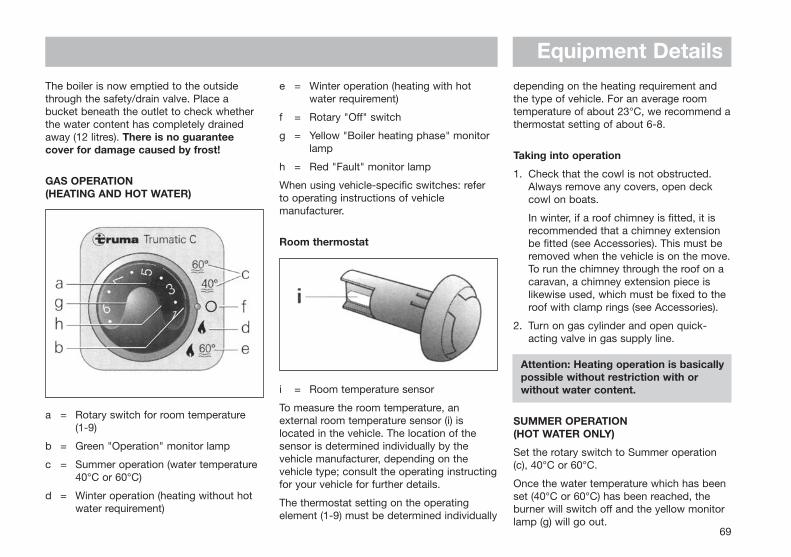
Equipment DetailsThe boiler is now emptied to the outsidethrough the safety/drain valve. Place abucket beneath the outlet to check whetherthe water content has completely drainedaway (12 litres). There is no guaranteecover for damage caused by frost!
GAS OPERATION (HEATING AND HOT WATER)
a = Rotary switch for room temperature (1-9)
b = Green "Operation" monitor lamp
c = Summer operation (water temperature40°C or 60°C)
d = Winter operation (heating without hotwater requirement)
e = Winter operation (heating with hotwater requirement)
f = Rotary "Off" switch
g = Yellow "Boiler heating phase" monitorlamp
h = Red "Fault" monitor lamp
When using vehicle-specific switches: referto operating instructions of vehiclemanufacturer.
Room thermostat
i = Room temperature sensor
To measure the room temperature, anexternal room temperature sensor (i) islocated in the vehicle. The location of thesensor is determined individually by thevehicle manufacturer, depending on thevehicle type; consult the operating instructingfor your vehicle for further details.
The thermostat setting on the operatingelement (1-9) must be determined individually
depending on the heating requirement andthe type of vehicle. For an average roomtemperature of about 23°C, we recommend athermostat setting of about 6-8.
Taking into operation
1. Check that the cowl is not obstructed.Always remove any covers, open deckcowl on boats.
In winter, if a roof chimney is fitted, it isrecommended that a chimney extensionbe fitted (see Accessories). This must beremoved when the vehicle is on the move.To run the chimney through the roof on acaravan, a chimney extension piece islikewise used, which must be fixed to theroof with clamp rings (see Accessories).
2. Turn on gas cylinder and open quick-acting valve in gas supply line.
Attention: Heating operation is basicallypossible without restriction with orwithout water content.
SUMMER OPERATION (HOT WATER ONLY)
Set the rotary switch to Summer operation(c), 40°C or 60°C.
Once the water temperature which has beenset (40°C or 60°C) has been reached, theburner will switch off and the yellow monitorlamp (g) will go out.
69
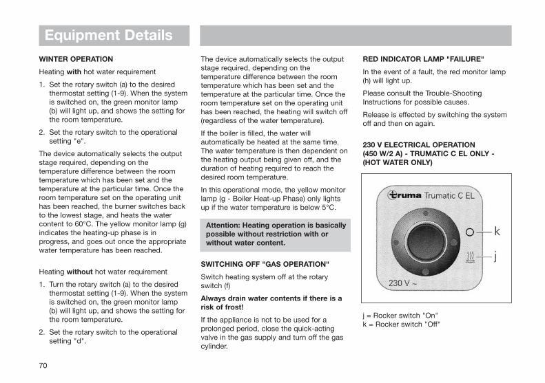
70
WINTER OPERATION
Heating with hot water requirement
1. Set the rotary switch (a) to the desiredthermostat setting (1-9). When the systemis switched on, the green monitor lamp(b) will light up, and shows the setting forthe room temperature.
2. Set the rotary switch to the operationalsetting "e".
The device automatically selects the outputstage required, depending on thetemperature difference between the roomtemperature which has been set and thetemperature at the particular time. Once theroom temperature set on the operating unithas been reached, the burner switches backto the lowest stage, and heats the watercontent to 60°C. The yellow monitor lamp (g)indicates the heating-up phase is inprogress, and goes out once the appropriatewater temperature has been reached.
Heating without hot water requirement
1. Turn the rotary switch (a) to the desiredthermostat setting (1-9). When the systemis switched on, the green monitor lamp(b) will light up, and shows the setting forthe room temperature.
2. Set the rotary switch to the operationalsetting "d".
The device automatically selects the outputstage required, depending on thetemperature difference between the roomtemperature which has been set and thetemperature at the particular time. Once theroom temperature set on the operating unithas been reached, the heating will switch off(regardless of the water temperature).
If the boiler is filled, the water willautomatically be heated at the same time.The water temperature is then dependent onthe heating output being given off, and theduration of heating required to reach thedesired room temperature.
In this operational mode, the yellow monitorlamp (g - Boiler Heat-up Phase) only lightsup if the water temperature is below 5°C.
Attention: Heating operation is basicallypossible without restriction with orwithout water content.
SWITCHING OFF "GAS OPERATION"
Switch heating system off at the rotaryswitch (f)
Always drain water contents if there is arisk of frost!
If the appliance is not to be used for aprolonged period, close the quick-actingvalve in the gas supply and turn off the gascylinder.
RED INDICATOR LAMP "FAILURE"
In the event of a fault, the red monitor lamp(h) will light up.
Please consult the Trouble-ShootingInstructions for possible causes.
Release is effected by switching the systemoff and then on again.
230 V ELECTRICAL OPERATION (450 W/2 A) - TRUMATIC C EL ONLY -(HOT WATER ONLY)
j = Rocker switch "On"k = Rocker switch "Off"
Equipment Details
71
Switch boiler on at the operating point (j).The indicator lamp indicates that the deviceis in operation.
When using vehicle-specific switches: referto operating instructions of vehiclemanufacturer.
Note: The water temperature cannot beselected, automatic temperature limitation atapprox. 60°C! For a faster heating up periodthe appliance can be simultaneouslyoperated with gas and electrical power.
MAINTENANCE
The water container used is made ofstainless steel, which is foodstuff-compatible.
Use wine vinegar for descalling the waterheater, this being introduced into theappliance via the water supply. Allow theproduct to react and then thoroughly flushout the appliance with plenty of fresh water.To sterilise the water we recommend"Certisil-Argento". Other products,particularly those containing chlorine areunsuitable.
To avoid infestation by micro-organisms, theboiler must be heated to 70°C at regularintervals (only possible in winter operation).
Do not use the water as drinking water!
Fuses
The fuse for the device is located on theelectronic control unit.
The fine-wire fuse must only be replaced bya fuse of the same design.
C 3402: 4 AT - slow-acting -C 6002: 6,3 AT - slow acting -
GENERAL SAFETY NOTES
If the gas system is leaking or if there is asmell of gas:
- Extinguish all naked flames!
- Do not smoke!
- Switch off the appliances!
- Shut off the gas cylinder!
- Open windows and door!
- Do not actuate any electrical switches!
- Have the entire system checked by anexpert!
Attention: Repairs may only be carriedout by an expert!
A new O-ring must always be installed afterdismantling the exhaust duct!
1. Any alteration to the appliance (includingexhaust duct and cowl) or the use ofspare parts and accessories which are
important to the function of the heaterand which are not original Truma parts, aswell as the non-observance of theinstallation and operating instructions, willlead to the cancelling of the guaranteeand exclusion of liability claims. It alsobecomes illegal to use the appliance, andin some countries this even makes itillegal to use the vehicle.
2. The operating pressure for the gas supplyis 30 mbar (or 28 mbar butane/37 mbarpropane) or 50 mbar and mustcorrespond to the operating pressure ofthe appliance (see name plate).
3. Liquid gas systems must accord with thetechnical and administrative regulationsof the particular country in which they arebeing used.
The testing of the gas system must berepeater every two years by a qualifiedspecialist and, if appropriate, confirmedon the inspection certificate.
The vehicle owner is alwaysresponsible for arranging theinspection.
4. Do not operate the appliance whenrefuelling the vehicle and when in thegarage.
5. During the initial operation of a brand newappliance (or after it has not been usedfor some time), a slight amount of fumes
Equipment Details
Equipment Detailsand smell may be noticed for a shortwhile. This can be remedied by runningthe heater at maximum out-put andensuring adequate room ventilation.
6. If the burner makes an unusual noise or ifthe flame lifts off, it is likely that theregulator is faulty and it is essential tohave it checked.
7. Items sensitive to heat (e.g. spray cans)must not be stored in the installationarea, since excess temperatures mayunder certain circumstances be incurredthere.
8. For the gas system only gas pressureregulators with protection against excesspressure, such as regulators with safetyvalves according to EN 12864, DIN 4811and VP 306, may be used. Werecommend the Truma DUB vehicleregulator or in the case of a two cylindergas installation that is only accessiblefrom the outside, the Truma Triomaticautomatic reserve switch-over. The Trumaregulators have been specially designedfor heavy-duty use in caravans, boats andvehicles. In addition to a safety valve forcountering excess pressure, they alsohave a pressure gauge with which youcan check that the installation is fully gastight.
Always connect the pressure regulatorsto the gas cylinders by hand, taking great
care! For temperatures around 0°C andbelow, the regulators should be operatedwith a defroster system (Eis-Ex). Inspectregulator connection hoses regularly forsigns of weakness. For winter operationonly use special frost resistant hoses.Gas cylinders must always be upright!
TECHNICAL DATA
Determined in accordance with prEN orTruma test conditions
Type of gas:Liquid gas (propane/butane)
Operating pressure: 30 or 50 mbar (refer to name plate)
Water contents: 12 Litres
Heating up time to approx. 70°C: approx 35 min (water heater)approx 80 min (heater + water heater)
Water pressure: max 2.8 bar
Rated thermal output:C 3402: 2000/3400 WC 6002: 2000/4000/6000 W
Gas consumption:C 3402: 170 - 285 g/hC 6002: 170 - 490 g/h
Air delivery volume (free-blowing without hot-air pipe)
C 3402: with 3 hot-air outlets max. 177 m3/h with 4 hot-air outlets max. 287 m3/hC 6002: with 4 hot-air outlets max. 287 m3/h
Current input at 12 V:Heater + water heater:C 3402: 0.2 - 2.4 AC 6002: 0.2 - 5.6 AHeating up of water heater: 0.4 AStand-by: 0.001 A
Current input of electrical safety/drainvalve at 12 V:0.035 A
Weight: 17.6 kg (without water contents)
ABG test mark:C 3402: 00C 6002: 301
Declaration of conformity:
The Trumatic C has been DVGW-tested andcomplies with the EC guideline for gasappliances (90/396/EEC) as well as theassociated EC guidelines. The following CEProduct Ident. No. is available for EUcountries:C 3402: CE-0085AS0121C 6002: CE-0085AS0122
The right to effect technical modifications isreserved.
72
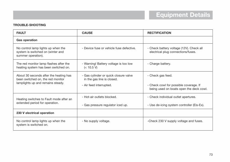
Equipment Details
73
Gas operation
No control lamp lights up when the system is switched on (winter and summer operation).
The red monitor lamp flashes after theheating system has been switched on.
About 30 seconds after the heating hasbeen switched on, the red monitorlamplights up and remains steady.
Heating switches to Fault mode after anextended period for operation.
- Device fuse or vehicle fuse defective.
- Warning! Battery voltage is too low (< 10.5 V)
- Gas cylinder or quick closure valve in the gas line is closed.
- Air feed interrupted.
- Hot-air outlets blocked.
- Gas pressure regulator iced up.
- Check battery voltage (12V). Check allelectrical plug connections/fuses.
- Charge battery.
- Check gas feed.
- Check cowl for possible coverage. Ifbeing used on boats open the deck cowl.
- Check individual outlet apertures.
- Use de-icing system controller (Eis-Ex).
230 V electrical operation
No control lamp lights up when the system is switched on.
- No supply voltage. -Check 230 V supply voltage and fuses.
FAULT CAUSE RECTIFICATION
TROUBLE-SHOOTING
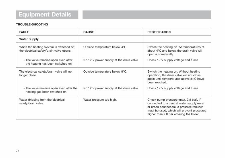
Equipment Details
74
Water Supply
When the heating system is switched off,the electrical safety/drain valve opens.
- The valve remains open even after the heating has been switched on.
The electrical safety/drain valve will nolonger close.
- The valve remains open even after theheating gas been switched on.
Water dripping from the electricalsafety/drain valve.
Outside temperature below 4°C.
No 12 V power supply at the drain valve.
Outside temperature below 8°C.
No 12 V power supply at the drain valve.
Water pressure too high.
Switch the heating on. At temperatures ofabout 4°C and below the drain valve willopen automatically.
Check 12 V supply voltage and fuses
Switch the heating on. Without heatingoperation, the drain valve will not closeagain until temperatures above 8∞C havebeen reached.
Check 12 V supply voltage and fuses
Check pump pressure (max. 2.8 bar). Ifconnected to a central water supply (ruralor urban connection), a pressure reducermust be used, which will prevent pressureshigher than 2.8 bar entering the boiler.
FAULT CAUSE RECTIFICATION
TROUBLE-SHOOTING
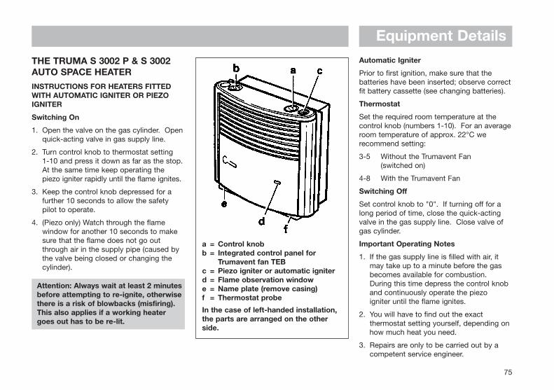
Equipment Details
75
THE TRUMA S 3002 P & S 3002AUTO SPACE HEATERINSTRUCTIONS FOR HEATERS FITTEDWITH AUTOMATIC IGNITER OR PIEZOIGNITER
Switching On
1. Open the valve on the gas cylinder. Openquick-acting valve in gas supply line.
2. Turn control knob to thermostat setting 1-10 and press it down as far as the stop.At the same time keep operating the piezo igniter rapidly until the flame ignites.
3. Keep the control knob depressed for a further 10 seconds to allow the safety pilot to operate.
4. (Piezo only) Watch through the flame window for another 10 seconds to make sure that the flame does not go out through air in the supply pipe (caused by the valve being closed or changing the cylinder).
Attention: Always wait at least 2 minutesbefore attempting to re-ignite, otherwisethere is a risk of blowbacks (misfiring).This also applies if a working heatergoes out has to be re-lit.
a = Control knobb = Integrated control panel for
Trumavent fan TEBc = Piezo igniter or automatic igniterd = Flame observation windowe = Name plate (remove casing)f = Thermostat probe
In the case of left-handed installation,the parts are arranged on the other side.
Automatic Igniter
Prior to first ignition, make sure that thebatteries have been inserted; observe correctfit battery cassette (see changing batteries).
Thermostat
Set the required room temperature at thecontrol knob (numbers 1-10). For an averageroom temperature of approx. 22°C werecommend setting:
3-5 Without the Trumavent Fan (switched on)
4-8 With the Trumavent Fan
Switching Off
Set control knob to "0". If turning off for along period of time, close the quick-actingvalve in the gas supply line. Close valve ofgas cylinder.
Important Operating Notes
1. If the gas supply line is filled with air, it may take up to a minute before the gas becomes available for combustion. During this time depress the control knob and continuously operate the piezo igniter until the flame ignites.
2. You will have to find out the exact thermostat setting yourself, depending on how much heat you need.
3. Repairs are only to be carried out by a competent service engineer.
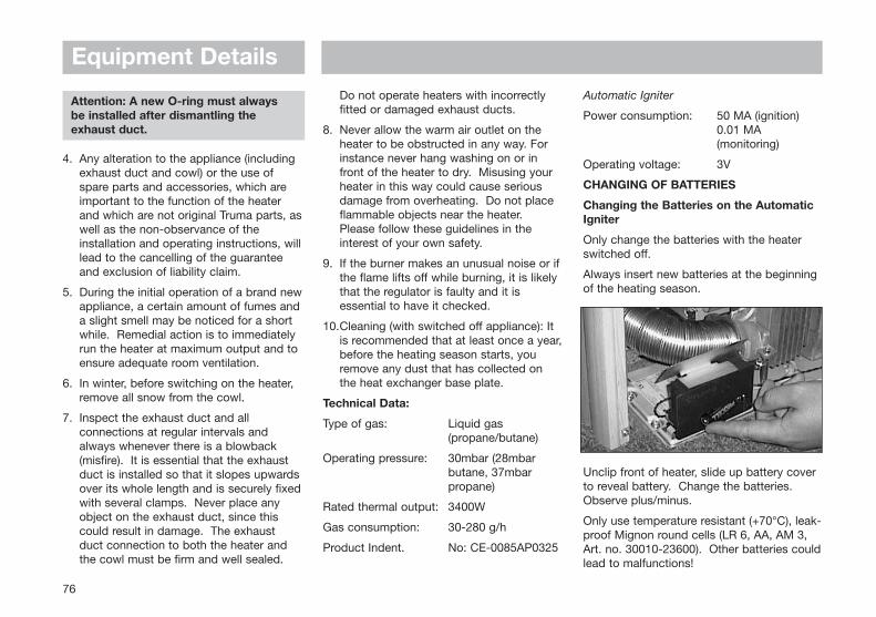
76
Attention: A new O-ring must always be installed after dismantling theexhaust duct.
4. Any alteration to the appliance (including exhaust duct and cowl) or the use of spare parts and accessories, which are important to the function of the heater and which are not original Truma parts, aswell as the non-observance of the installation and operating instructions, willlead to the cancelling of the guarantee and exclusion of liability claim.
5. During the initial operation of a brand newappliance, a certain amount of fumes anda slight smell may be noticed for a short while. Remedial action is to immediately run the heater at maximum output and to ensure adequate room ventilation.
6. In winter, before switching on the heater, remove all snow from the cowl.
7. Inspect the exhaust duct and all connections at regular intervals and always whenever there is a blowback (misfire). It is essential that the exhaust duct is installed so that it slopes upwardsover its whole length and is securely fixedwith several clamps. Never place any object on the exhaust duct, since this could result in damage. The exhaust duct connection to both the heater and the cowl must be firm and well sealed.
Do not operate heaters with incorrectly fitted or damaged exhaust ducts.
8. Never allow the warm air outlet on the heater to be obstructed in any way. For instance never hang washing on or in front of the heater to dry. Misusing your heater in this way could cause serious damage from overheating. Do not place flammable objects near the heater. Please follow these guidelines in the interest of your own safety.
9. If the burner makes an unusual noise or ifthe flame lifts off while burning, it is likely that the regulator is faulty and it is essential to have it checked.
10.Cleaning (with switched off appliance): It is recommended that at least once a year,before the heating season starts, you remove any dust that has collected on the heat exchanger base plate.
Technical Data:
Type of gas: Liquid gas (propane/butane)
Operating pressure: 30mbar (28mbar butane, 37mbar propane)
Rated thermal output: 3400W
Gas consumption: 30-280 g/h
Product Indent. No: CE-0085AP0325
Automatic Igniter
Power consumption: 50 MA (ignition)0.01 MA (monitoring)
Operating voltage: 3V
CHANGING OF BATTERIES
Changing the Batteries on the AutomaticIgniter
Only change the batteries with the heaterswitched off.
Always insert new batteries at the beginningof the heating season.
Unclip front of heater, slide up battery coverto reveal battery. Change the batteries.Observe plus/minus.
Only use temperature resistant (+70°C), leak-proof Mignon round cells (LR 6, AA, AM 3,Art. no. 30010-23600). Other batteries couldlead to malfunctions!
Equipment Details
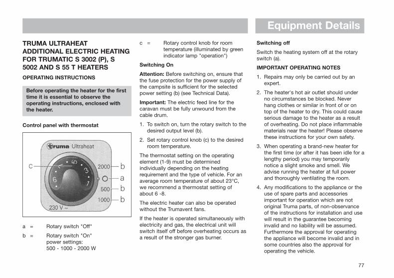
77
TRUMA ULTRAHEATADDITIONAL ELECTRIC HEATINGFOR TRUMATIC S 3002 (P), S5002 AND S 55 T HEATERSOPERATING INSTRUCTIONS
Before operating the heater for the firsttime it is essential to observe theoperating instructions, enclosed with the heater.
Control panel with thermostat
a = Rotary switch "Off"
b = Rotary switch "On"power settings: 500 - 1000 - 2000 W
c = Rotary control knob for roomtemperature (illuminated by greenindicator lamp "operation")
Switching On
Attention: Before switching on, ensure thatthe fuse protection for the power supply ofthe campsite is sufficient for the selectedpower setting (b) (see Technical Data).
Important: The electric feed line for thecaravan must be fully unwound from thecable drum.
1. To switch on, turn the rotary switch to thedesired output level (b).
2. Set rotary control knob (c) to the desiredroom temperature.
The thermostat setting on the operatingelement (1-9) must be determinedindividually depending on the heatingrequirement and the type of vehicle. For anaverage room temperature of about 23°C,we recommend a thermostat setting ofabout 6 -8.
The electric heater can also be operatedwithout the Trumavent fans.
If the heater is operated simultaneously withelectricity and gas, the electrical unit willswitch itself off before overheating occurs asa result of the stronger gas burner.
Switching off
Switch the heating system off at the rotaryswitch (a).
IMPORTANT OPERATING NOTES
1. Repairs may only be carried out by anexpert.
2. The heater's hot air outlet should underno circumstances be blocked. Neverhang clothes or similar in front of or ontop of the heater to dry. This could causeserious damage to the heater as a resultof overheating. Do not place inflammablematerials near the heater! Please observethese instructions for your own safety.
3. When operating a brand-new heater forthe first time (or after it has been idle for alengthy period) you may temporarilynotice a slight smoke and smell. Weadvise running the heater at full powerand thoroughly ventilating the room.
4. Any modifications to the appliance or theuse of spare parts and accessoriesimportant for operation which are notoriginal Truma parts, of non-observanceof the instructions for installation and usewill result in the guarantee becominginvalid and no liability will be assumed.Furthermore the approval for operatingthe appliance will become invalid and insome countries also the approval foroperating the vehicle.
Equipment Details
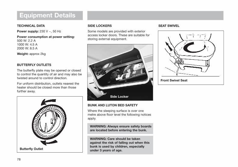
78
TECHNICAL DATA
Power supply: 230 V ~, 50 Hz
Power consumption at power setting:500 W: 2.2 A1000 W: 4.5 A2000 W: 8.5 A
Weight: approx 2kg
BUTTERFLY OUTLETS
The butterfly plate may be opened or closedto control the quantity of air and may also betwisted around to control direction.
For uniform distribution, outlets nearest theheater should be closed more than thosefurther away.
SIDE LOCKERS
Some models are provided with exterioraccess locker doors. These are suitable forstoring external equipment.
BUNK AND LUTON BED SAFETY
Where the sleeping surface is over onemetre above floor level the following noticesapply.
WARNING: Always ensure safety boards are located before entering the bunk.
WARNING: Care should be taken against the risk of falling out when thisbunk is used by children, especiallyunder 3 years of age.
SEAT SWIVEL
Butterfly Outlet
Side Locker
Equipment Details
Front Swivel Seat
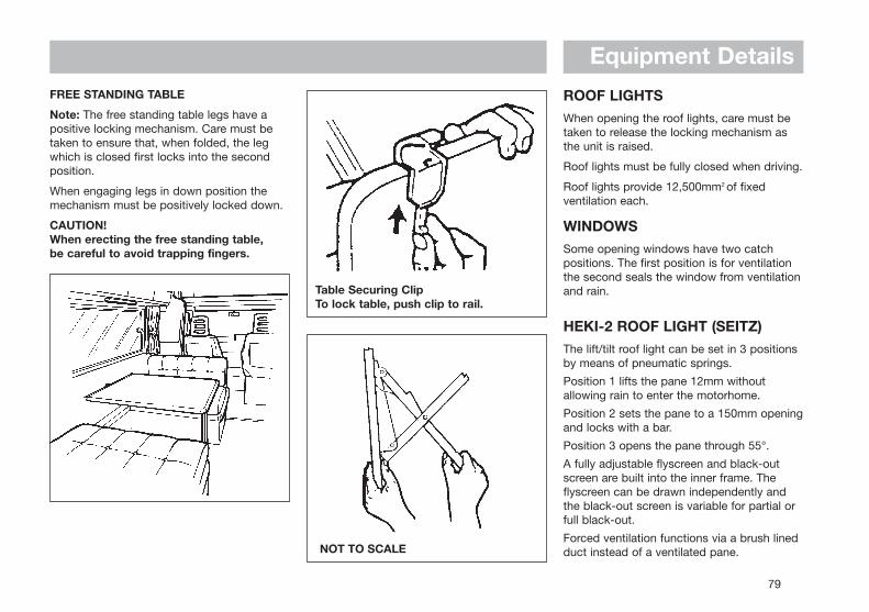
79
Equipment DetailsFREE STANDING TABLE
Note: The free standing table legs have apositive locking mechanism. Care must betaken to ensure that, when folded, the legwhich is closed first locks into the secondposition.
When engaging legs in down position themechanism must be positively locked down.
CAUTION!When erecting the free standing table, be careful to avoid trapping fingers.
Table Securing ClipTo lock table, push clip to rail.
ROOF LIGHTSWhen opening the roof lights, care must betaken to release the locking mechanism asthe unit is raised.
Roof lights must be fully closed when driving.
Roof lights provide 12,500mm2 of fixedventilation each.
WINDOWSSome opening windows have two catchpositions. The first position is for ventilationthe second seals the window from ventilationand rain.
HEKI-2 ROOF LIGHT (SEITZ)The lift/tilt roof light can be set in 3 positionsby means of pneumatic springs.
Position 1 lifts the pane 12mm withoutallowing rain to enter the motorhome.
Position 2 sets the pane to a 150mm openingand locks with a bar.
Position 3 opens the pane through 55°.
A fully adjustable flyscreen and black-outscreen are built into the inner frame. Theflyscreen can be drawn independently andthe black-out screen is variable for partial orfull black-out.
Forced ventilation functions via a brush linedduct instead of a ventilated pane.NOT TO SCALE
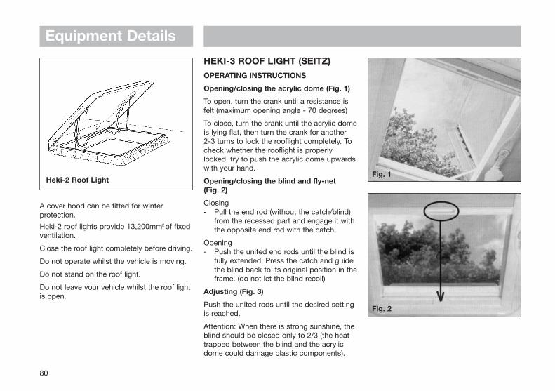
80
A cover hood can be fitted for winterprotection.
Heki-2 roof lights provide 13,200mm2 of fixedventilation.
Close the roof light completely before driving.
Do not operate whilst the vehicle is moving.
Do not stand on the roof light.
Do not leave your vehicle whilst the roof lightis open.
HEKI-3 ROOF LIGHT (SEITZ)OPERATING INSTRUCTIONS
Opening/closing the acrylic dome (Fig. 1)
To open, turn the crank until a resistance isfelt (maximum opening angle - 70 degrees)
To close, turn the crank until the acrylic domeis lying flat, then turn the crank for another 2-3 turns to lock the rooflight completely. Tocheck whether the rooflight is properlylocked, try to push the acrylic dome upwardswith your hand.
Opening/closing the blind and fly-net (Fig. 2)
Closing- Pull the end rod (without the catch/blind)
from the recessed part and engage it withthe opposite end rod with the catch.
Opening- Push the united end rods until the blind is
fully extended. Press the catch and guidethe blind back to its original position in theframe. (do not let the blind recoil)
Adjusting (Fig. 3)
Push the united rods until the desired settingis reached.
Attention: When there is strong sunshine, theblind should be closed only to 2/3 (the heattrapped between the blind and the acrylicdome could damage plastic components).
Heki-2 Roof LightFig. 1
Fig. 2
Equipment Details
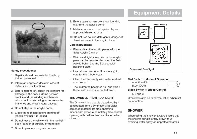
81
Omnivent Rooflight
Fig. 3
Safety precautions:
1. Repairs should be carried out only bytrained personnel
2. Inform an approved dealer in case ofdefects and malfunctions
3. Before starting off, check the rooflight fordamage in the acrylic dome (tensioncracks) and the winding mechanismwhich could arise owing to, for example,branches and other natural causes.
4. Do not step in the acrylic dome
5. Close the roof light before starting off(check whether it is locked)
6. Do not leave the vehicle with the rooflightopen (danger of burglary or from rain)
7. Do not open in strong wind or rain
8. Before opening, remove snow, ice, dirt,etc. from the acrylic dome
9. Malfunctions are to be repaired by anapproved dealer at once
10. Do not use caustic detergents (danger oftension cracks in the acrylic dome)
Care instructions:
- Please clean the acrylic panes with theSeitz Acrylic Cleaner.
- Stains and light scratches on the acrylicpane can be removed by using the SeitzAcrylic Polish and the Seitz specialpolishing cloth.
- Use talcum powder (4 times yearly) tocare for the rubber seals
- Clean the blinds only with water and mildsoap suds
- The guarantee becomes null and void ifthese instructions are not followed.
THE OMNIVENT (12V) ROOFLIGHT
The Omnivent is a double glazed rooflightconstructed from a synthetic ultra-violetscreened material. Its side operatingmechanism allows a completely free centralopening with built-in fixed ventilation whenclosed.
Red Switch = Mode of OperationInduction (IN)Expel (OUT)
Black Switch = Speed Control
1, 2 and 3
Omnivents give no fixed ventilation when seton induction.
SHOWERWhen using the shower, always ensure thatthe shower curtain is fully drawn thusavoiding water spray on unprotected areas.
Equipment Details
INOFFOUT
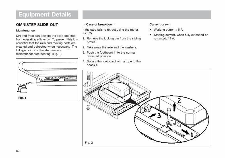
Equipment Details
OMNISTEP SLIDE-OUTMaintenance
Dirt and frost can prevent the slide-out stepfrom operating efficiently. To prevent this it isessential that the rails and moving parts arecleaned and defrosted when necessary. Thelinkage points of the step are in amaintenance free bearing. (Fig. 1)
In Case of breakdown
If the step fails to retract using the motor (Fig. 2)
1. Remove the locking pin from the sliding profile.
2. Take away the axle and the washers.
3. Push the footboard in to the normal retracted position.
4. Secure the footboard with a rope to the chassis.
Current drawn
• Working current : 5 A.
• Starting current, when fully extended or retracted: 14 A.
82
Fig. 1
Fig. 2
MOTORHOMECARE
Modifications - DIY ................................................................. 84
Motorhome Exterior ............................................................... 84
Motorhome Interior ................................................................ 85
Chassis and Rear Axle ........................................................... 86
Exhaust Systems .................................................................... 86
Winterisation/Storage ............................................................ 86
Motorhome Care
MODIFICATIONS - DIY WORKOwners need to be aware that carrying outDIY modifications to your motorhome may incertain instances, invalidate the warrantycover and could also affect the safety andstructure of the motorhome.
Before carrying out any DIY work within thewarranty period (3/5) years please checkwith your nearest Swift Group dealer orcontact Supercare customer services on01482 875740 for advice.
WARNING: In the interest of safety,replacement parts for an appliance shallconform to the appliance manufacturersspecification and should be fitted by himor his authorised agent.
MOTORHOME EXTERIORPAINTWORK
The exterior of your coachbuilt motorhome isfinished with glass reinforced plastic (GRP)which is very durable and easy to cleanowing to its smooth finish. GRP is now usedextensively in modern motorhomeconstruction and if cared for properly willenhance the appearance of your vehicle. Tomaintain a showroom finish wash themotorhome regularly with a mild detergent,rinse with cold water and leather off. A good
quality, silicon free car wax may be appliedwhich will make washing even easier.
Under no circumstances use any abrasivecleaning agents on the exterior of yourmotorhome. Stubborn stains may beremoved by using a soft cloth and a milddetergent.
WARNING: Overzealous use of detergents may loosen the decals and/or badges.
WARNING: Care should be taken as the silicon in some polishes can attack the rubber used on the exterior for seals and gaskets.
MOULDINGS
Some mouldings are anodised aluminiumand will retain their lustre for a long period ifno abrasive materials are used to cleanthem. If your motorhome is subjected toconstant changes of temperature, masticmay seep from joints between themouldings. Any excess that appears can beremoved by simply wiping with a soft cloth.
WARNING: Do not wash motorhome with a high pressure washer. These can cause permanent damage to the seals of your motorhome.
ACRYLIC WINDOWS
The windows in your motorhome are fullydouble glazed and with care will remainsparkling and scratch-free.
Keeping your acrylic windows sparkling:
Small Scratches: For small scratches use aliquid metal polish or a proprietary acrylicpolish of a suitable grade dependent uponthe severity of the scratches.
Cleaning: Wash down as you would yourcar. Do not use a sponge on dirty windows.When all dirt has been removed, dry with aleather or similar type cloth. The catches and stays do not require lubricating.
Removing Tar: Use a proprietary tarremover on your double glazed windows, it is obtainable from most leading caraccessory or Do-It-Yourself shops. Do not use petrol or other chemicals.
84
Motorhome Care
MOTORHOME INTERIORSIDE WALLS AND ROOF LINING
A simple wipe over with a damp cloth and avery mild detergent is all that is needed.
SOFT FURNISHINGS
These should be vacuumed occasionally toremove grit and sand and help to keep itssmart appearance and ensure long life. Theupholstery can be cleaned with a mild,reputable upholstery cleaner. It isrecommended that the curtains are drycleaned only.
WORK SURFACES
Work surfaces are made with heat resistanttops.
Note: You should not stand very hot itemson any of the work surfaces, especiallymodels with plastic moulded sink anddrainers.
CUPBOARD CATCHES
It is advisable to lightly oil all cupboardcatches, sliding bolts, telescopic bed slidesand hinges from time to time.
BATHROOM, SHOWER ROOM ANDKITCHEN EQUIPMENT
All the Thermoplastic parts in these areashave easy clean surfaces. To ensure long lifeand prevent damage you must not use anycleaning materials at all and ensure watertemperatures do not exceed 70°C, (puttingcold water in first is suggested). After everyuse it is essential that you rinse with cleanwater only and wipe with a soft damp cloth.Failure to follow these simple instructionsmay result in premature failure or crackingwhich will not be covered by any guarantees(including extended warranties).
To improve the appearance of your showerduck board (model specific), lightly brushoccasionally with vegetable oil.
CONDENSATION
Condensation will always occur whenhumidity inside your motorhome exceeds 60per cent. Correct heating and ventilating ofyour motorhome will help to controlcondensation. We therefore recommend thatyou make sure your motorhome is heatedand ventilated correctly at all times of theyear, particularly in inclement or very wetweather. It will assist in reducingcondensation if the windows are left in thenight latch position.
FURNITURE
A simple wipe over with a damp cloth shouldbe all that is required. Polishing with aproprietary brand of wax polish enhancesand maintains furniture in showroomcondition. Follow these guidelines to ensureyour investment is receiving the very bestattention.
It must be remembered that because theframes of some doors are made of ash,which is a natural product, they can beaffected by temperature and humidity andmay bow under certain conditions. Asconditions change they may revert to theiroriginal positions.
85
Motorhome Care
CHASSIS AND REAR AXLESome models are built on Fiat Ducato orPeugeot Boxer base vehicles, the chassis ofwhich has been converted by Al-Ko. Thisconversion provides a hot dipped galvanisedsteel chassis coupled with a wide track rearaxle utilising steel torsion bar suspension,imparting vastly improved stability and roadholding.
Al-Ko EXHAUST SYSTEMA standard Fiat exhaust system is fittedutilising an Al-Ko modified tail pipe, availablethrough your approved dealer.
A standard Fiat exhaust system is fitted to allother models, with the addition of a SwiftGroup tail pipe.
WINTERISATION/STORAGEThis is probably an opportune moment toarrange for the motorhome to have itsannual service at your appointed dealer.
The following applies wherever yourmotorhome is stored particularly during thewinter months.
Do not park near trees or larch type fences,due to possible wind damage.
Keep any grass around the floor of themotorhome short, to maintain air flow andstop any possible damp getting into the
motorhome.
It is advised that the motorhome is ventilatedregularly throughout the winterisation/storage period, opening windows, doors androoflight when possible.
General
All moving parts should be checked for freeoperation.
Clean all cooking appliances and refrigerator.
Lubrication should be carried out at thepoints illustrated in the general notes onchassis maintenance.
Charge the on-board battery every 2 months.
Leave the refrigerator door open.
Leave furniture doors and lockers open toallow air to circulate fully.
Soft Furnishings
Clean and dust the upholstery and ifpossible remove before placing themotorhome into winter storage. Alternatively,stand the cushions on their edges to allowcirculation of air. This will reduce thepossibility of dampness from condensation.
Keep curtains or blinds closed, to minimisefading of furniture.
Wheels and Tyres
Do not store in one position with partially
deflated tyres. The tyre walls will suffer andpresent a real danger of blow outs,especially when travelling at faster speedsthan are allowed in the UK.
The wheels should be turned every couple ofweeks.
If you are removing the wheels, follow thejacking procedure for changing a wheel.
Water System
Ensure water pump is turned off.
Lift kitchen sink unit lid and clip in openposition.
All single lever mixer taps, including theshower control, should have the lever movedto the central position and lifted to the openposition for hot and cold.
All conventional taps should be opened.
Remove shower head and place in thekitchen drawer. Let the shower hose draininto the shower tray and then return toholder.
Drain water tanks:Internal tanks - open inline valve adjacent tothe tank. Valve is open when handle is inlinewith valve.
Drain water heater:Truma Store and Combi boilers - openyellow handle on inline valve adjacent toheater. Valve is open when yellow handle isvertical.
86
Motorhome CareThe Thetford Cassette porta potti is easilywinterised for storage. Empty the fresh watertank using the drain tube/fresh water tanklevel indicator (level indicator on electronicmodels only). Pull the lever indicator/draintube down from top plug position andoutward through door opening to drain waterfrom the tank.
Empty the water fill funnel by pulling thebottle away from tank. Remove the smallwater cap on the filler bottom, allowing waterto drain from the water funnel.
Do not tighten caps, this helps in keepingunit dry.
The pour out spout and vent plug can beremoved. Seals should be greased ifnecessary with acid-free vaseline.
Remove the drain stop plugs on the freshwater pipes. These are located through thefloor on the underside of the motorhome.
If a fresh water tank is fitted, drain the tankvia underfloor drain tap/plug.
Leave the drain plugs and taps open.
The motorhome may be left in this conditionover winter or until ready to use. It isrecommended to leave the taps in the openposition during storage.
Recommissioning the Water System
Fill the fresh water tank on the ThetfordCassette porta potti (certain models only)using a hose or jerrycan until the water in thefunnel reaches the neck. Tank capacity is 15litres. Aqua Rinse may be added to improvecleaning of bowl and flushing of unit.Replace cap. Swing back the water fill funneluntil it touches the water tank.
Add Aqua Kem (100 ml) into the Cassette (or120 ml if using Aqua Kem Bio) through thepour out spout. Add small amount of waterthrough the pour out spout and replace thecap.
Close the cold taps and ensure all the drainplugs are fitted.
It is advisable after storage to flush the watersystem initially with a sterilising agent (suchas Milton), and then with water repeatinguntil the system is well flushed through.
Connect the pump.
Fill the system with water until water flowsfreely from the hot taps. About 2 gallons ofwater will be required. Close the hot taps.
Appliances
Before starting motor caravanning afterstorage, check all gas appliances andelectrical points.
Note: Preferably not less than once a year,the electrical installation should be inspectedand tested by a qualified electrician.
After storage it is advisable to air themotorhome and clean throughout, especiallycooking appliances and the refrigerator.
Replace the bedding and wheels if they wereremoved for storage.
ImportantAlways follow the manufacturer'srecommended procedures after use of fittedequipment in the motorhome and beforestoring for any length of time.
87
USEFULINFORMATION
Swift Group Spares and After Sales.......................................90
Repair Facilities ...................................................................... 90
Caravan Clubs ..........................................................................91
Motoring Organisations ...........................................................91
Trade Association.....................................................................91
Useful Information
MOTORHOME INFORMATION
Date of purchase ........................................
Supplying dealer ........................................
CAB Chassis No ........................................
Motorhome Serial No .................................
SWIFT GROUP SPARES AND AFTER SALESThere are numerous items available fromyour dealer in the specially packaged ‘SwiftGroup Spares’, ranging from door catchesthrough to spare wheels and touch-uppaints. Please note that all after salesenquiries must be directed through yoursupplying dealer. The after sales service atthe factory is geared to support our dealernetwork as is the service provided byappliance manufacturers.
NB Please remember to quote your buildwhen ordering any items from your dealer.
Swift Group Websitewww.swiftleisure.co.uk
REPAIR FACILITIESShould you be unfortunate enough to suffera major accident with your motorhome it iscomforting to know that Swift has acompletely separate repair shop facilitywhere their fully trained experts willundertake all types of major damage repairwork.
Repairs of a minor nature should be referredfirst to your local dealer.
90
Useful Information
91
The enjoyment of your motorhome can begreatly enhanced by membership of one ormore of the various caravanning, motoringand holiday clubs. Here are some usefuladdresses:
CLUBS
The Caravan ClubEast Grinstead HouseEast GrinsteadWest Sussex RH19 1UATel: 01342 326944
The Camping and Caravanning ClubGreenfields HouseWestwood WayCoventryWest MidlandsTel: 01203 694995
MOTORING ORGANISATIONS
Automobile Association (AA)Fanum HouseBasingstokeHants. RG1 2EATel: 0990 448866www.theaa.co.uke-mail: [email protected]
RAC Motoring ServicesRAC HouseM1 CrossBrent TerraceLondon NW2 1BXTel: 0990 722722
Green Flag National BreakdownPO Box 3001 Cotes LaneLeeds LS99 2LZTel: 0345 670345
TRADE ASSOCIATION
National Caravan CouncilCatherine HouseVictoria RoadAldershotHampshire GU11 1SSTel: 01252 318251www.martex.co.uk/ncce-mail: [email protected]
93
Swift Group LimitedDunswell Road, Cottingham,East Yorkshire HU16 4JXTel: (01482) 875740e-mail: [email protected] site: www.swiftleisure.co.uk
© 2002 SWIFT GROUP LTD
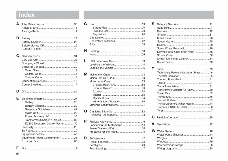
94
A After Sales Support ......................................90Arrival at Site ................................................13Awnings/Tents ..............................................14
B Battery ..........................................................28Battery Charger ............................................28Before Moving Off ..........................................6Butterfly Outlets............................................78
C Caravan Clubs ..............................................91CEC 225 Unit................................................29Changing a Wheel ........................................10Codes of Conduct ..........................................2
Camp Sites.................................................2Coastal Code .............................................4Country Code.............................................4
Connecting Services ....................................15Corner Steadies............................................14
D DIY ................................................................84
E Electrical Systems ........................................27Battery......................................................28Battery Charger ........................................30Generator Guidelines ...............................42Mains Unit ................................................29Power System (12V) .................................30Transformer/Charger KT12SM .................30EC200 Electronic Control System............30
Electricity ......................................................22En Route .........................................................9Equipment Details ........................................43Equipment Power Consumption ..................25Extractor Fan ................................................60
F Fire ................................................................12
G Gas ...............................................................19Butane Gas ..............................................20Propane Gas ............................................20Regulators ................................................20
Gas Safety ....................................................21Generator Guidelines....................................42Grills..............................................................58
H Heating .........................................................68Hobs .............................................................56
L LCD Panel over Door....................................30Levelling the Vehicle .....................................14Loading the Vehicle ........................................6
M Mains Inlet Cable..........................................23Mains Unit (CEC 225) ...................................29Motorhome Care ..........................................83
Chassis/Rear Axle ....................................86Exhaust System .......................................86Exterior .....................................................84Interior ......................................................85Modifications............................................84Winterisation/Storage...............................86
Motoring Organisations ................................91
O Omnistep Slide-Out......................................82Overseas Connections .................................23
P Payload Allowance .........................................6Positioning the Motorhome ..........................14Power System (12V) .....................................30Preparing for the Road ...................................5
R Refrigerators .................................................47Repair Facilities ............................................90Rooflights......................................................79Roof Loading ..................................................7
S Safety & Security ..........................................11Seat Belts .......................................................7Security.........................................................12Shower..........................................................81Side Locker...................................................78Space Heaters ..............................................75Spares...........................................................90Spare Wheel Removal ..................................10Stoves Hobs, Grills and Ovens ....................56Stoves Oven .................................................58SMEV 400 Series Cooker .............................54Swivel Seats .................................................78
T Table .............................................................79Technically Permissible Laden Mass..............6Thermal Insulation .......................................25Thetford Porta Potti ......................................61Toilets............................................................61Trade Association .........................................91Transformer/Charger KT12SM......................30Travel Catch..................................................52Truma 3002...................................................75Truma Ultraheat ............................................77Truma Ultrastore Water Heater.....................44Trumatic C3402 & C6002 .............................68Tyres................................................................7
U Useful Information ........................................89
V Ventilation .....................................................12
W Water System ...............................................16Water Pump (Shurflo) ...................................44Weights ...........................................................6Windows .......................................................79Winterisation/Storage ...................................86Wiring diagrams ...........................................24
Index

Quality with Style
SWIFT MOTORHOMES, DUNSWELL ROAD, COTTINGHAM, EAST YORKSHIRE HU16 4JX.TEL: 01482 875740 FAX: 01482 840082
e-mail: [email protected] website: www.swiftmotorhomes.co.uk
A MEMBER OF THE SWIFT GROUP
Issued November 2002 1048640