Embed Size (px)
Citation preview

To our valued customer
Thank you for choosing a quality HARDI 12 Volt Sprayer.
This manual covers the safety, operation and maintenance procedures for the swift, profesional and ATV range of HARDI 12 Volt sprayers and includes detailed spare parts drawings and information for your convenience.
Please visit our web site at: www.hardi.com.au for more information about our product range, spraying and crop protection. For sales, service and spare parts information contact your local HARDI dealer.
Caution: All operators intending to use this equipment, or any of its systems must read and understand this entire publication. Pay particular attention to safety warnings, prior to operation. In addition, where the equipment is to be used in conjunction with a motorised vehicle (such as an ATV) all operators must be fully conversant with the manufacturers recommendations for such equipment, be of a suitable age, have undergone appropriate training and be the holder of the correct license under state and federal law. The safety sections and warnings in this publication must be thoroughly read and understood.
WARNING: Failure to comply with the above may result in personal injury, death or damage to the equipment, property, crops or the environment.
Note: The technical data contained herein is to the best knowledge of HARDI Australia Pty Ltd correct at the time of publishing. HARDI Australia Pty Ltd reserves the right to make changes in design, features, accessories, specifications and instructions at any time without prior notice and is without obligation in relation to products purchased before or after such changes and assumes no responsibility for any errors, inaccuracies or omissions.
Copyright: Design, text, illustrations and layout in this manual are produced and published by HARDI Australia Pty Ltd and are protected by copyright law. Copyright © 2006 HARDI Australia Pty Ltd.
Swift 12 Volt Sprayer RangeOperators Manual
P/No: 67024204-AU-02/06
HARDI AustraliaCross Keys Road Cavan South Australia
Document type Operator’s Manual
Subject 12 Volt Sprayer Range
Number of pages 32
Date produced 01 / 10 / 2006
Produced by Tech Services
B.O.M. included No
Part number 67024204
Publication No 1

1 - Introduction
Table of contents
1 IntroductionTable of contents ..................................................1. 1Warranty information ............................................1. 1
2 SafetySafety information ............................................. 2. 1Safety alert icons ..................................................2. 1Beware of overhead powerlines ...........................2. 1Introduction ..........................................................2. 2Chemical safety ...................................................2. 2General safety ......................................................2. 2Chemical safety ....................................................2. 2Safety equipment ..................................................2. 2Contaminated clothing ..........................................2. 2Australian Safety Standards .................................2. 2Chemical information ............................................2. 2Be a responsible operator ....................................2. 2Spray drift .............................................................2. 3Mechanical safety .................................................2. 3
3 ATV safetyIntroduction ...........................................................3. 1ATV risks...............................................................3. 1Fitting attachments ...............................................3. 1Ride-Safe: a few tips to remember .......................3. 1Remeber these points in sumary ..........................3. 1Risk assessment ..................................................3. 1
4 Risk AssessmentStop, look think, assess respond! .........................4. 1 Respond ...............................................................4. 1Minimising risks: Owner’s responsibility ...............4. 1Employer’s responsibility ......................................4. 1In addition make sure you ....................................4. 1Before fitting a HARDI attacment to your ATV ......4. 1Prior to operating an ATV with a HARDI attachment ................................................ 4.1
5 DescriptionProduct range .......................................................5. 1Swift range ............................................................5. 1ATV range .............................................................5. 1Professional range ................................................5. 1Tank features ........................................................5. 1Pumps ..................................................................5. 1Pressure control ...................................................5. 1HARDI 60 S handgun ...........................................5. 1Spray Lance .........................................................5. 1
6 OperationIntended use ........................................................6. 1Getting started .....................................................6. 1Securing tank to ATV ...........................................6. 1ATV tank position .................................................6. 112 Volt power connection .....................................6. 1Power harness .....................................................6. 1Pump types ....................................................... 6. 2
Demand type ........................................................6. 2Control type ..........................................................6. 2Control 3 type .......................................................6. 2Getting started..................................................... 6. 2Lance operation....................................................6. 2HARDI 60 S handgun ...........................................6. 3Pressure control ...................................................6. 3Control 3 distribution valves .................................6. 3Sprayer calibration................................................6. 3Handgun nozzles .................................................6. 3Application rate.....................................................6. 4Handgun calibration .............................................6. 4Handgun technique ..............................................6. 4Amount of chemical per tank ................................6. 4
7 MaintenancePeriodic service procedures ............................ 7. 1Servicing fluid joints .............................................7. 1Servicing the filter assembly ................................7. 1Internal suction filter assembly .............................7. 2Servicing Flo-Jet assemblies ...............................7. 2Bypass pumps ......................................................7. 22100 Series Demand Pump .................................7. 34100 Series Demand Pump .................................7. 35500Triplex Series ................................................7. 3Cleaning and decontamination ........................ 7. 5Introduction ..........................................................7. 5Minimising risks ....................................................7. 5Sprayer and Chemical Hygiene ............................7. 5Cleaning procedure ........................................... 7. 6
8 Spare partsSwift 75 litre Saddle Pack .....................................8. 1Swift 25, 50 and 100 Litre ....................................8. 2Rachet Tie Down Strap ........................................8. 250 litre Swift Bike Sprayer ....................................8. 3Professional Series 250 Litre ...............................8. 4Professional Series 100, 300 Litre .......................8. 5Pressure Regulator Valve .....................................8. 6Filter Assembly .....................................................8. 6HARDI Hose Reel ...............................................8. 7LF, 4100, 5500 Pumps .........................................8. 8HARDI 60 S Handgun ..........................................8. 9Control 3 Distribution Manifold ........................... 8.10HARDI Lance ..................................................... 8.11HARDI Lance extension ..................................... 8.12HARDI Nozzles .................................................. 8.13Decals ................................................................ 8.14
Warranty informationPlease record your purchase details below:
Date of purchase:
Where purchased:
Sprayer model:
Serial number:
1. 1

A
B
2 - Safety
Safety Information
2. 1
Beware of overhead power linesWarning: Operating agricultural machinery near powerlines presents a potentially fatal hazard. It is the responsibility of the operator to ensure that minimum safe clearances are strictly observed, in particular when transporting implements, when spraying, raising, tilting or lowering booms. Also be aware that during hot or windy weather sagging or swaying of powerlines can reduce safe working clearances.
Typical powerline structures for South Australia (guide only and subject to change without notice) Powerline structures and voltages can vary in different regions of Australia. Consult your local electricity supply authority for details of minimum safe clearances in your area.
A: Minimum safe clearance from conductor for vehicles and implements. B: Minimum safe clearance from conductor for persons and livestock
Safety alert icons This manual contains safety information which could prevent crop damage or save a life. Safety information is included in each section and is highlighted by the following icons according to the level of potential risk.
Warning: This indicates the highest level of hazard alert. Failure to comply with the information contained here could result in personal injury or death.
Caution: This indicates that mandatory action is required . Failure to comply with the information contained here could result in damage to crops, the equipment and / or the environment.
Note: This indicates practical information regarding safe and effective use of the equipment and it’s systems.

IntroductionAlways read chemical labels and follow the instructions. (See chemical safety section for further details)Always wash and rinse equipment and tools before servicing and after use (see section on de-contamination).Avoid un-necessary contamination risk. Pressure test the equipment with clean water prior to filling with chemicals. Never eat, drink or smoke while spraying or working with contaminated equipment.Always change clothes after spraying and carefully contain and launder (or dispose of) to prevent cross-contamination.Never drink water from any sprayer tank or assume that the contents of a ‘clean water’ tank is safe to drink.In case of poisoning identify chemicals used and seek medical advice immediately.
Chemical safety Chemical contamination poses a serious health risk. It is the responsibility of the operator to ensure correct safety protection equipment and clothing is used.
Safety equipmentDepending on which type of chemical is used, some or all of the following protective clothing and equipment will be required (see diagram this page):
1: Headgear, 2: Safety goggles or face shield, 3: Respirator, 4 : Chemical resistant coveralls, 5: Chemical resistant gloves, 6: Chemical resistant boots.
Contaminated clothingContaminated clothing should be removed and safely stored and laundered taking care not to contaminate the inside of the tractor cab.
Australian Safety StandardsProtective clothing and equipment must conform to Australian Safety Standards and must always be used when handling chemicals, operating the sprayer and during the cleaning and decontamination process.
Chemical InformationChemical labels are registered by the National Registration Authority. Laws vary from state to state regarding the purpose for which a chemical may be used so consult your local authorities.
Always read the chemical manufacturer’s labels as they contain critical information about your safety and the environment.
Be a responsible operatorAlways follow label recomendations when disposing of chemical residue (see section on decontamination).
Warning: Agricultural chemicals can be dangerous. Always read chemical labels and carefully follow safety recommendations.
6
5
4
3
2
1
2 - Safety
Safety Information Continued
2. 2

2 - Safety
Safety Information Continued
2. 3
Mechanical safetyNever service or repair the equipment while it’s operating. De-pressurize equipment after use and before servicing.Disconnect power and ensure that all components are in the recommended state and position before servicing.Always replace all safety devices and shields immediately after servicing.When servicing electrical components disconnect and isolate any power leads and remove any flammable or explosive material from the area.
General safetyKeep unauthorised persons live stock and children away from the equipment at all times. Never attempt to enter a tank or allow some one else to do so for any reason.
Warning: All operators must read all related material before attempting use. Local law may require operators to be certified before using motorised farm machinery, spray equipment and some chemicals. Consult local authorities.
Note: Although every effort has been made to include as much safety information as practical, it is impossible to anticipate every scenario that may present a risk. It is therefore the responsibility of the operator to exercise safe operating practices. If in any doubt, do not proceed! Consult the apropriate Authorities.
Note: Specific safety warnings appear at the beginning of each chapter where applicable. Read them carefully. If any portion of this instruction book is unclear contact your HARDI dealer for further information.
Spray drift
Caution: Spray particles diverted and carried by the wind are referred to as spray-drift. Serious crop damage can occur as a result of spray drift. Climatic conditions can also increase the risk of spray drift onto neighbouring crops. Remember, neighbouring crops may be highly sensitive to some chemicals.
HARDI Australia would like to point out that although calibration information is provided, it is vitally important that you read the chemical manufacturer’s labels and adhere to their recommendations for the correct use of their product. The manufacturers label will also state the products limitations and warnings.
Wind speed and direction, temperature, humidity and chemical properties should all be considered when determining if conditions are suitable for spraying. Contact your local Department of Primary Industries for details of relevant publications explaining the risks and how best to minimise them. It is the responsibility of the sprayer operator to ensure that the spraying conditions are suitable for the application of the chemical to be used.
Caution: After changing chemicals or crops the entire sprayer must be flushed and decontaminated. This includes disconnecting the filters and pressure relief valve and cleaning residue and sediment from inside all hoses, valves and filters. Failure to do so may lead to serious crop damage.

Warning: In the interests of promoting safe work practices, HARDI Australia has included the follow-ing information. It could prevent serious personal injury or death to yourself, another person or even a child. It must be read, understood and used responsibly when making your risk assessment (as described in the next section).
Note: This section is not presented as an exhaustive study of the risks associated with Ag Bike’s / ATV’s, but highlights some of the additional risks which may be encountered when using an ATV in conjunction with an attachment such as a HARDI sprayer. To become fully informed therefore, all operators must also refer to the ATV manufacturer’s safety information, Work-safe literature, and State and Federal law specific to the use of ATV’s and Ag-bikes before proceeding. Further compulsory information is also included in a new section outlining the basic principles of ‘Risk assessment’.
Warning: HARDI Australia does not authorise, condone or endorse the use of it’s products in any way associated with 3 wheel ATV’s. It should also be noted that some ATV’s are designated as “Sports” or “Recreation” models and should never be fitted with a HARDI ATV Sprayer under any circumstances.
IntroductionThe HARDI “ATV” range of sprayers has been designed to be fitted to some “All terrain vehicle’s” or ATV’s.The term ‘Ag Bike’ refers to all motor bikes with two three or four wheels used for farm work. Three and four wheelers are also referred to as ‘All Terrain Vehicles’ or ATV’s, however the 3 wheeled variety ATV’s are no longer manufactured due to thier unstable nature and high number of accidents. HARDI Australia does not authorise, condone or endorse the use of it’s products in any way associated with 3 wheeled ATV’s.
ATV RisksThe high number of personal injuries and deaths associated with Ag bikes / ATV’s on farms in Australia has been documented for some time, but farm related injuries and fatalities associated with these kinds of machines continue to occur. There is no question ATV’s are dangerous. The majority of related injuries and deaths are the result of vehicle overturns or rollovers.
Fitting attachments (such as a sprayer) to an ATV. • Only fit attachments that comply with the ATV manufacturers loading specifications as listed in the vehicles operation manual. • Take note of overall loading capacity as well as carry rack or tongue towing capacity. • Do not exceed the manufacturers weight limits under any circumstances. • When calculating safe working loads remember to add the sprayer’s net weight plus the amount of fluid you intend to carry: (1 litre water = 1 kg).
Ride-Safe: a few tips to remember. • Always use an approved motorcycle safety helmet and clothing. • Always follow the manufacturer’s instructions when loading or operating your ATV. • Ensure all operators are properly trained in ATV operation • Ensure all operators are aware of risks and apply sound Risk assessment principles. • Further information is available through Worksafe (VIC, WA,) Workplace Health & Safety (QLD) ATV manufacturers and professional ATV training facilities.
Remember these points in sumary: • An ATV’s handling characteristics and stability will change when adding attachments. • As you add weight, the centre of gravity changes making the ATV respond diferently and potentialy become less stable. This greatly increases the risk of rollovers. • Terrain you drive over safely and easily when the ATV is unladen, may not be safe to negotiate with a loaded ATV.
Risk AssessmentIn further response to the issue of Farm Safety, in particular where the use of ATV’s is involved, Hardi Australia supports and promotes the use of a Risk Assessment when embarking on any job. A Risk Assessment involves taking into consideration a variety of factors which could, either individualy or in combination, cause an unsafe situation for the operator or other persons.
ATV’s / Ag Bikes: Ride Safe!
3 - ATV / Ag-bike Safety
3. 1

Risk assessment: Every one’s responsability!
4 - Risk Assessment
4. 1
Warning:Stop, Look, Think, Assess, Respond!Risk assessments should involve a physical check-list which will include such factors as:
• Operator skill level in ATV handling. • ATV’s mechanical condition and service history. • Attachment is secured and within ATV manufacturers weight loading specifications. • Operator is of age, properly trained and has the skills to deal with emergencies. • Type and condition of terrain to be encountered during the planned task. • Speed of operation. • ATV’s centre of gravity and weight distribution. • Environmental and weather conditions.
RespondWhere safety is concerned a “casual” attitude is just plain dangerous. Disregard of the points listed above have been associated with injury causation and must be considered every time any task is being planned. If for any reason an unacceptable risk is detected do not proceed. Identify the area of risk and if possible, respond by correcting the situation and then repeat your risk assessment. If it is still unsafe, DON’T RISK IT!
Minimising risks: Owner’s responsibilityAs an ATV operator, it is your responsability to ensure that you fully understand the dangers associated with operating an ATV and that you know the appropriate safety precautions to take in order to minimise any risk of an accident. As an ATV owner, it is your responsability to ensure that your ATV is mechanically sound and that anyone intending to ride it has the necessary skills, training and understanding to operate it safely.
Employer’s responsibilityIf you are an employer you have a duty of care under the Occupational Health And Safety Act 1984 to ensure Ag bikes including ATV’s are safely maintained and used in accordance with the manufacturers specifications, and that employees riding them are adequately trained and are wearing the correct and aproved safety equipment.
In addition make sure you: • Read and understand the ATV’s manual, paying particular attention to the safety information and maximum loading capacity. • Know the limitations of your machine. • Know your own rider skill level, abilities and limitations. • Farmiliarize yourself with all the warning stickers on the machine. • Know the machine’s service history and run through a mental safety check list daily.
Note: Before fitting a HARDI attachment to an ATV• Always ensure attachments are properly secured to the ATV with an apropriate anchor. • ATV’s must be mechanically sound with an aproved and documented service history.• Brakes must be regularly serviced, and tyre pressures set as per manufacturers specifications.
• Suspension and controls must also be in excelent working condition and functioning.
Prior to operating an ATV with a HARDI attachment • Perform a risk assessment of the task and area it will be carried out on. • Slow down, always drive at a speed which allows you to safely avoid sudden changes in terrain, other farm equipment, live stock, and any other unexpected obstacles. • Be aware sudden shifts in load affect ATV stability. Be aware of the movement of fluid. • Plan work tasks so that the need to travel is reduced and avoid riding when tired, when visibility is poor, when it’s raining, or under the influence of any kind of drugs or alcohol. • Operators must be properly trained and minimum of 16 years of age. • Where practical, provide professional rider training and access to training videos. • Always wear an approved motorcycle helmet, strong over the ankle boots, protective gloves, eye protection and a long sleeve shirt and pants in adition to chemical PPE’s. • Do not carry passengers. • Never exceed maximum specified tongue weight or maximum loading capacity. • Remove the attachment when not in use or the ATV is to be used for another purpose. • Be aware of fatigue as it can affect your ability to control the ATV safely. • Be aware that operating an attachment while riding may affect your ability to control the ATV safely so practice and slow down.

5. 1
5 - Description
Product Range
There are three main groups in the HARDI 12 Volt rangeThe Swift Range • Light weight durable design • Demand activated fluid system • Tank sizes of 25, 50 and 100 litres. • Reliable and robust 12 Volt operated Flojet diaphragm pump (models LF 14 or the 3000-501) • Choice of HARDI Spray-lance or S-60 handgun (depending on your specific requirements)
The ATV Range • Tanks shape designed to suit the ATV range of products. • Tank sizes of 50 and 75 litres capacity. • Optional “Demand type” or “Adjustable pressure control” fluid systems. • Optional 3 way distribution valve to facilitate a combination boom* and hand gun (*75 litre model only). • Optional boom* configurations are available to suit your specific requirements. • Reliable and robust 12 Volt operated Flojet diaphragm pump 3000-501 or the 3521-13 • Supplied with either a HARDI lance or handgun. • A ratchet tie down strap is supplied to ensure tank is fixed to the vehicle.
The Professional Range • Specially shaped tanks of sizes 100, 250 and 300 litres. • Optional “Demand type” or “Adjustable pressure control” fluid systems. • Reliable and robust 12 Volt operated Flojet diaphragm pump 3000-501 the 3521-13 or the 4100-501 • A cartridge style suction filter fitted between the pump and tank for ease of cleaning. • Hose reel and optional 20 metre length of high quality hose (250 litre model) • The robust and powerful HARDI 60 s handgun as standard equipment on all models.
Tank features • Moulded from high-density polyethylene. • Easy to clean and translucent for easy liquid level monitoring. • Tough impact resistant. Pumps • The flojet pumps feature 12 volt operation and are fitted with viton valves and satoprene diaphragms. • The pumps have permanent magnet motors and ball bearings so can run dry without damage. Pressure control • Spray pressure is easily and progresively controlled with optional rotating hand operated bypass valve. • Manufactured from tough polypropylene and feature a high quality pressure gauge for reliable and accurate metering. HARDI 60 S Handgun • Durable brass valve encased in a tough Polypropylene housing. • ‘Easy-grip’ design to fit comfortably in the hand during operation. • Wide grip trigger with a ’Safety Lock-Off’ feature for your added security. • Reversable ceramic nozzel disc to easily accomodate higher or lower capacity spray jobs as required. • Fully adjustable spray fan with a simple twist of the barrel allows the operator to choose a narrow spray angle or a wide cone spray angle as needed. • ‘O’ Ring type swivel hose coupling for effortless directional control. • Light weight.
Spray Lance • Durable polypropylene construction with simple trigger operation and safety lock. • Built in easy clean filter for extra nozzle protection. • ‘O’ Ring type swivel hose coupling for effortless directional control. • Adjustable nozzel cone and light weight fibre glass extention tube.

6. 1
6 - Operation
Intended use
The ATV version Swift’s are supplied with a ratchet tie down strap to secure the sprayer in place. This strap is long enough to pass under the frame and will pass over the tank twice to ensure the unit is correctly secured and the bike and the sprayer act as one. Excess length of strap should be secured so as to ensure it cannot become entangled with the operator or the machine.
(Ratchet tie down strap supplied with ATV model Swift’s only)
Warning: The sprayer must be secured to ensure no movement of the tank on the ATV. A sudden shift in load could cause a rollover/flipover of the ATV.
ATV Tank PositionThe sprayer should be positioned so as to minimise risk of contamination to the operator whilst still maintaining the best vehicle ballance and stability as posible. The pump should be turned away from the operator and the hoses routed so as to protect the operator from chemical in the event of a pump or hose failure.
Caution: Do not exceed the vehicle manufactures specified safe load and carrying capacity. Remember that 1 litre of water weighs 1 kilogram and add the total weight of the water and the chemicals to the empty (net) weight of the sprayer when assessing the sprayers suitability for the vehicle you intend to use.
12 Volt connectionThe HARDI 12 Volt Sprayer range is designed and built in Australia to run on a 12 Volt DC power source only. The sprayer’s power supply harness should be connected directly to the vehicles 12 Volt DC battery. Due to the risk of voltage spikes from the vehicles charging system, connection to any other circuit on the vehicle voids pump warranty.
Power harnessThe sprayer is supplied with a fused 12 volt power supply harness. The fused end with the two eyelets bolts directly to the vehicles positive and negative battery terminals, the other end plugs neatly into the pump’s power harness coming straight out of the pump (mounted on the sprayer itself).
Ensure that the fused cable is connected to the positive terminal of the battery before the negative terminal is connected, finaly routing the wires neatly and safely from the battery to the sprayer. Make sure the wiring is protected from damage, and can’t rub or be crushed. On models which feature the 4100-501 Flo-jet pump, an inline isolation switch is fitted. All other pumps have an on/off switch located at the end of the pump motor.
Caution: Lead acid batteries are filled with highly corrosive sulphuric acid. As explosive gases can form around a battery, ensure that the battery vents are all closed to reduce the risk of an explosion due to a stray electrical spark.
Securing the tank to the vehiclePlace the sprayer in a suitable position on the vehicle. If you are using the sprayer on a utility or the transport frame of a tractor it is important that the sprayer is sitting on a flat surface and is firmly secured to prevent it from sliding around and falling off.
��������������������������������������������������������������������������������������������������������������
Intended useThe HARDI 12 Volt range of sprayers are designed primarily for the application of agricultural chemicals to plants and soil, including: herbicides, insecticides, fungicides, liquid fertilisers and organic formulations. HARDI Australia does not authorise or endorse the sprayer’s use for any other purpose. Please note that some local Councils may require operators of spray equipment to be certified. It is strongly recommended they undergo training in spray techniques and the safe handling of plant protection chemicals before attempting use.

Lance operation To operate the lance, transfer some liquid to the tank and activate the switch on the pump. Gently depress the trigger (A) ensuring the lance is directed in a safe direction, away from any persons.
The lance is fitted with an adjustable nozzle cone (B) that allows the operator to control the spray pattern progresively from a narrow stream to a very wide cone. Best distance is achieved by a narrow stream whilst optimum coverage is obtained by a wider angle cone. Again, practice with fresh water in the sprayer on an area of concrete where the resulting coverage can be seen.
AB
All HARDI 12 volt sprayers may be supplied with a choice of three operating systems:
Demand type: A demand system means the pump is fitted with a pressure sensitive switch that turns the pump off when the pressure builds to a preset point. When the trigger on the Lance or Handgun is shut, flow is interupted and the system pressure builds, throwing the switch and shutting the pump off. Similarly when the operator opens the trigger on the Lance or Handgun the flow is immediately restored. This causes the pressure in the circuit to drop, tripping the switch again and allowing the pump to start.
Control type: A control system has an adjustable pressure valve that allows the operator to set pressure at the desired rate. This system allows the operator to choose the spraying pressure and if lance or handgun is shut off pump will continue to run and the volume from pump will bypass over relief and return back to tank. The pump is turned off by switch.
Control 3 type: Similar to the above control unit, but with a 3-way distribution valve fitted in line. This three way distribution valve allows one valve for the Lance or Handgun and 2 auxillary valves for booms etc.
Getting startedWith the sprayer connected to 12 volt power and secured to the vehicle, half fill the tank with clean water, and activate the power switch to start the pump.
The pump should start working immediately and build pressure to maximum (as in the case of a demand system) or run continuously (as in the case of a control system).
With the sprayer running, test the lance and handgun and make sure all the distribution valves (if fitted) are functioning correctly and operate their intended fluid circuits. Operate the fluid system and check for correct operation and leaks including the pressure control valve, the pressure gauge, all hoses, fittings and accessories if fitted.
Warning: Only after thoroughly testing and close examination for leaks should chemicals be added to the sprayer. Always test your sprayer with clean water first. Read all the chemical manufacturers literature, labels and instructions before you attempt to add any chemicals. Use extreme caution and always wear the specified safety equipment when adding or handling chemicals (see section on chemical safety, page 2. 3).
Note: When fitted with the 4100-505 pump, the 100 litre professional unit has an inline switch fitted in the 12volt power supply harness.
Note: In the case of a demand type sprayer: If the pressure control valve is wound in fully, it is normal for the system to trigger the safety switch and cycle the pump on and off momentarily as the pressure rises and falls within the system. Opening the pressure regulator will prevent this
6 - Operation
Operation
6. 2

6 - Operation
6. 3
Sprayer calibrationHand gun nozzlesThe S60 Hand gun features a adjustable nozzle (supplied with the gun) which enables the operator to select two different primary spray volume settings depending on which way the nozzle is facing in the cap.
Nozzle directionNozzle Type Pressure in Bar Litre/Min Litre /Min1099-20 2 (max volume soid stream) 3.35 2.37
B
C
A
Handgun operation With the sprayer half full of clean water as described above and the pump on, point the gun in a safe direction and away from any persons and livestock, and release the safety (A). Squeeze the red trigger (B) to activate the gun.
You can sellect a narrow jet-stream to a very wide angle cone simply by rotating the barrel on the front of the gun (C). The best coverage is obtained by a wider angle setting however the best reach or distance is achieved by a narrow “Jet-stream” setting.
Pressure controlThe pressure control is a spring loaded bypass valve that regulates the system pressure by allowing extra fluid delivered by the pump to be bypassed or recirculated back to the tank. The pressure gauge allows the operator to set and monitor the desired circuit pressure.
OperationWhen the combined output capacity required of the nozzles is less than the pump’s output rate, the pressure control valve allows the operator to control the application rate by varying the amount of bypass back to the tank.
First, the control valve should be fully released which means turning the handle anticlockwise before starting the pump. This allows the fluid to be returned to tank. The pump should then be started and the pressure control handle gradually turned clockwise to restrict the bypass and direct the flow to the nozzles.
Control 3 distribution valvesThe control 3 system features a simple distribution valve manafold system designed to distribute the fluid to any combination of up to 3 fluid circuits. The valve manifold is located on the pressure delivery side of the pump. Operating the individual “flip over” levers opens the valves and activates the associated fluid circuit. On Off
Operation
CalibrationTo ensure precise and safe applications in the field effective calibration is essential. Calibration should always be done with clean water and before adding any chemicals. Follow this practice when calibrating: • Test the sprayer with fresh water as previously described. • Re-fill the tank to half way and mark the fluid level (use a marker pen for accuracy). • Spray a 100 square meter area of ground to ‘run off’ (an area 10 metres by 10 metres). • Using a container of known volume, carefully restore the previously marked fluid level and record the volume required. • Now multiply this amount by 100 to calculate the application rate in litres per hectare.

Amount of chemical per tankThere are two accepted methods of determining the amount of chemical to be added to a given volume of water. Follow the chemical manufacturers instructions for spot spraying or alternatively use the following formula:
Tank Volume x Dose Rate* = Chemical per TankCalibrated rate of sprayer inLiters per hectare
*Dose = rate as specified on the label
Before adding chemicals: • Test the sprayer correctly as previously described. • Make sure the sprayer is secured to the vehicle before chemicals are added. • Always wear safety equipment (see section on chemical safety, Page 2. 2). • Follow chemical manufacturers instructions. • Tank should be 1/3 full of clean water before any chemicals are added.
6 - Operation
Sprayer calibration
6. 4
Application rateThe term “Application rate” is used with reference to chemical dosage and is generaly measured in Litres per hectare (L/ha) or in the case of a Hand-gun in Litres per minute (L/min). Correct chemical doseage is crucial to successful spraying and begins by following the chemical manufacturers mixing and dilution ratio instructions to the letter. A number of other variable factors including system pressure and the speed of the sprayer should also be considered.
Hand gun calibrationIn the case of a Hand-gun or a Spray-lance, sprayer speed is not a factor due to the difficulty in regulating the speed at which the nozzel passes over the foalage. In this case spray is applied until the point of “Run-off”. Attention to the influence of the following variable factors will be necisary when practicing and perfecting your technique: • The cone angle (controlled by rotating the barrel of the gun). • The pressure the operator sets the system to run on. • Nozzle size and the direction in which it is fitted in the nozzle cap. • Gun speed and application technique.
Note: • If the fluid pressure is reduced with the pressure control valve, the volume of
chemical delivered per minute is reduced (slower operation, may help control spray) • If the speed at which the gun is moving changes, the amount of spray hitting the plant per minute will change. • Nozzle size and position will also influence the other factors significantly. • Also be aware that droplet size is influenced by spray pressure. • For further information on sprayer calibration purchase a copy of “Spraying Techniques” from your HARDI dealer or visit our web site at: www.hardi-aus.com
Hand-gun spray technique: ‘Run-off’In the case of a handgun or lance, it is essential the operator practice applying the spray target area till just before ‘run-off’ occurs. This technique involves laying enough spray droplets onto the plant to cover the surface of the leaves but stopping before the droplets begin to congeal and ‘run-off’ the plant.
Note: • Always ensure chemicals are mixed and diluted to the manufacturers specifications. • Any further application past the point of run-off means wasted chemical and increased risk of plant overdose and environmental damage. • For correct hand gun technique try and keep the gun moving, ie: sweep the handgun from side to side across the plant’s foleage. • Always practice and perfect your technique first using fresh water.
Note: It is recomended that you practice your spray technique (using fresh water) on a hard dry surface such as concrete, where the influence of system pressure, spray angle, fan size, gun speed and nozzle position on performance may easily be seen.
7 - Maintenance
7. 1
Servicing fluid jointsMost fluid joints found on the HARDI 12 Volt range of sprayers consist of a hose pushed over a barbed nipple, and secured with an automotive style stainless steel hose clamp.
Servicing the filter assemblyThere are two types of filters found on the HARDI 12 volt range which require occasional service:
• External suction filter. • Internal suction filter.
Where clean water is available a reasonable service interval may fall between 10 to 15 operating hours depending on the type of chemical being sprayed.
Where poor quality water is being used (ie: bore or dam) the screen may require cleaning more often.
Technical tip: When trouble shooting pressure related faults, always check the system’s filters.
Procedure for checking and cleaning suction filter1. Having taken appropriate safety precautions to avoid contact with chemicals (see chemical safety page 2. 2), disconnect the power supply and place the equipment on a solid surface. 2. Locate the filter assembly and rotate the bowl anti-clockwise until it comes free of the filter body.
3. Remove the screen, check for damage and using a small brush and water, clear away any foreign material.
4. Flush the filter’s housing, lubricate all ‘O’ rings with a non mineral based lubricant and reassemble the components carefully, tightening only by hand. In the case of a contaminated water supply, it is recommended you flush the entire fluid system and refill with clean water.
Periodic service procedures
Filter assembly
A3242024
A322000.040
A322000.030
A322000.050

7 - Maintenance
Periodic service procedures
7. 2
Internal suction filter assembly (S1274)Where good quality water is available a reasonable service interval may fall between 10 to 15 operating hours as above, depending on the type of chemical being sprayed.
Where poor quality water is being used (ie: bore or dam) the screen may require cleaning more often.
Technical tip: When trouble shooting pressure related faults, always check the system’s filters.
Procedure1. Having taken appropriate safety precautions to avoid contact with chemicals (see chemical safety section), disconnect the power supply and place the equipment on a solid surface.
2. With the sprayer’s tank drained, remove the lid and manoeuvre the suction or fluid pick up hose up through the lid to access the suction filter.
3. Remove the clamp and filter from the hose and check the filter screen for damage. If found to be serviceable clear the screen using a small brush water or a suitable neutralising solution and re-assemble, using a new stainless hose clamp (part no: C14 / 8)
4. If the screen is damaged, order a replacement under part number: S1274 from your HARDI dealer.
Disassemble Pump Head1. Take precautions to prevent injury due to chemical contact during maintenance.2. Flush pump with water or neutralising agent before servicing if the pump has been used to transport chemicals.3. Disconnect the power to the pump motor.4. Remove the pressure switch cover by removing the single screw (A) from pressure switch and remove switch cover.5. Remove wires (E) from pressure switch by gently sliding female spage terminals away from the male spade connectors.6. Remove two screws (B) from the front of pump head.7. Slide pump head (C) away from motor(D) assembly.
Reassemble Pump head (C) to Motor (D)1. Assemble the pump head (C) to motor(D) aligning screw tabs.2. Install screws (B) and tighten to 15 inch ounces of torque.3. Reconstruct wires (E) to pressure switch. Wires can be connected to either terminal of the pressure switch.4. Install the pressure switch cover with screw (A)5. Reconnect pump to liquid source.6. Reconnect pump to power source.7. Allow pump to prime with discharge line or spray valve open.8. Check for leaks in discharge system.
A BF DCE
LF Series Pump

7 - Maintenance
7. 3
Periodic service procedures
4100 Series “Quad” Pump
4100 Series Service ProceedureDisassembly: 1. Remove four pump head screws (A). 2. Rotate bearing cover (H) so drain notch is aligned with cam/bearing assembly set screw (L). 3. Loosen set screw with 1/8” allen wrench and slide pump head off shaft. Always use complete FLOJET repair kits upon reassembly.
Reassembly: 1. Install new single-piece outer piston (F) into lower housíng (H) with piston tops pointing away from motor. 2. Slightly bend outer piston (F) along premolded crease to aid assembly. 3. Place diaphragm in lower housing (H) with the molded O-ring seals facing away from motor. 4. Insert each inner piston (D) through diaphragm into outer piston. 5. Turn each piston until fully seated. 6. Align cam/bearing assembly (G) with outer piston (F). 7. Secure with cam/piston screws using 18 inch pounds of torque. 8. Reassemble lower housing (D to H) to motor. Set screw MUST be positioned over shaft indentation and secured tightly. 9. Reassemble pump upper housing (A, B, C). 10. Check that ferrules are installed in upper housing and O-ring is properly seated before inserting check valve assembly (C) into upper housing (B). 11. Align pump assembly to motor and tighten pump head screws evenly with 25 inch pounds of torque.
Key Description A Pump screw with washers & ferrules B Upper housing assembly C Check valve assembly & O-rings, ferrules E Diaphragm with pistons & screws G Cam bearing with set screws
Key Description H Bearing cover I Motor assembly J Motor rear end bell assembly K Fan / shroud assembly (if required) M Base plate / grommet assembly
A B
C D E F G
H L
I J K
M

7 - Maintenance
Periodic service procedures
7. 4
Disassembly: Pump housing (B).1. Disconnect power to the pump motor. 2. Remove the pressure switch cover (A) and remove the two wire leads from the switch spade connectors. 3. Remove the six screws from the upper housing (B). 4. Remove the upper housing from the check valve and diaphragm/lower housing assemblies (C&D). Check valve assembly (C) (to replace check valve, follow steps 1 through 6). 5. The check valve housing and O-rings are located on the diaphrgm/lower housing assembly (D). 6. Remove the check valve (C) from the diaphragm/lower housing assembly (D) (pull valve body from the diaphragm).
Diaphragm/ cam/lower housing assembly (D)7. Remove the diaphragm / cam / lower housing assembly (D) from the motor front bell end adapter (E).
Motor replacement (F)8. To replace the motor only follow steps 1 through 7.9. Remove the front end bell assembly (5) from the motor (you will require a 3mm Allen wrench. 10. Remove the four Allen head screws from the motor adapter and remove the adapter and O-rings.
Reassembly: Pressure switch assembly (A)1. Install the switch diaphragm into upper housing. Check the diaphragm for the material mark located in the centre of the new diaphragm. V is vor VITON, B is for BUNA, and E is for EPDM. Select the correct material for the installation. 2. Install the switch body over the diaphragm, align the screw holes and install the two mounting screws.3. Reinstall the two wires onto the spade connectors, then install the switch cover and screw.
Check valve assembly (C)4. Check valve assemblyInstall the O-ring into the O-ring groove located on the discharge side of the check valve assembly (C). 5. Install the check valve assembly into the diaphragm (D) aligning the check valve body with the diaphragm seal walls (push into secure to the diaphragm).
Upper housing assembly (B)6. With the check valve assembly installed on to the diaphragm, place the upper housing assembly onto the pre-assembled lower housing diaphragm/ cam assembly (D). 7. Align the cam with the motor shaft and slide the cam and pump head assembly onto the motor shaft (F) (lube themotor shaft with a small amount of light grease). 8. Check the discharge location (see arrow on the front of port) for correct port orientation (discharge right is the standard position). 9. Install the six pump head screws through the upper housing and through the lower housing into the front end bell assembly (B, D &E) aligning the three pins on the motor adapter with the upper housing and tighten securely (torque to 25 inch-pounds).
Triplex Series
A
B
C
D
E
F
G
Key Description A Pressure switch assembly B Upper housing with switch C Check valve assembly with O-ring D Diaphragm/lower housing assembly
Key Description E Front end bell assembly F Motor assembly G Mounting feet

7 - Maintenance
7. 5
IntroductionAgricultural chemicals often contain materials which can react adversely if combined through accidental cross-contamination.
Caution: Minute traces of chemical residue can cause damage to sensitive plants/ crops if the sprayer is not decontaminated properly.
Note: Some chemicals, by their nature are more persistent than others and require a ‘de-activating agent’ to neutralise particles of active material which may still be pressent somewhere in the sprayer’s fluid system. See the chemical label for cleaning details specific to your product.
Warning: Agricultural Chemicals can be dangerous. See “Chemical Safety” in section 1 of this manualfor further details.
For these reasons an effective cleaning and de-contamination routine is essential.
Minimising risks • Think each job through and assess the risks (see “Risk Assessment” previous section) • Pay strict attention to detail during cleaning and de-contamination proceedures. • Read and pay close attention to chemical manufacturers instructions. • Ensure adequet training in chemical safety for all operators. • Clean prior to changing chemicals and changing crops. • Clean in preparation for off season storage. • Always stick to your program, no short cuts.
Sprayer and Chemical Hygeine...Not Negotiable!Good “Sprayer and Chemical Hygeine” is a “Non-Negotiable” part of safe spraying practice. Washing your equipment thoroughly also helps avoid blockages and promotes smooth, trouble free operation when it’s time to spray.
Note:• Always use personal safety equipment and launder all clothing in an appropriate manner.• Chemical labels contain important information regarding cleaning and decontamination including safety precautions and de-activating agents.
• Don’t assume it’s clean, chemical residues may be trapped in the fluid system. • Clean inside and outside of the sprayer. • Clean any equipment used for measuring, mixing, handling and induction of chemicals. • Clean all hoses, valves, spray lines, nozzles, inside tank lid’s etc. • Clean external surfaces of the sprayer, filters and ATV. • Some chemicals are more persistent than others. Their particles can tend to adhere to sprayer surfaces requiring more stringent decontamination procedures. • Always use the recomended de-activating agent. • Clean up before plant protection chemicals dry out. • When using high pressure cleaners, avoid electrical junctions and re-apply lubricant to moving parts. • Accurate calibration helps minimise left over spray solution when the job is finished.
SummaryEffective cleaning: • Improves the quality of the spray job. • Reduces the risk of residual chemical related crop damage. • Aids in the containment of residual chemical waste. • Renders the sprayer safe for the next operator and spray job. • Improves the sprayers reliability and performance and extends component life.
Note: Local laws may vary from state to state regarding the use and disposal of certain agricultural chemicals. Contact your local authorities for details. Information can also be obtained from the Department of Primary Industries and the Environmental Protection Authority.
Periodic service procedures, cont. Cleaning and De-contaminationMotor assembly (B)10. Install the O-ring into the front bell end assembly (E). 11. Install the front end bell assembly onto the new motor by aligning the adapter with the motor housing and screw bosses (F). 12. Install the four (3mm) Allen screws through the adapter and into the motor and secure (E&F) (Apply a thin layer of screw Loctite 272 to secure these screws). 13. Install the pump head by following steps 6 through 9.

7 - Maintenance
7. 6
Cleaning procedure
Recommended six step strategyThere are six steps to an effective cleaning and de-contamination program which must be performed before an acceptable level of cleanliness can be expected.
1. Read 2. Flush 3. Drain 4. Decontaminate 5. Inspect 6. Store
1. ReadFarmiliarise yourself with the chemical manufacturers information and note any special instructions regarding cleaning proceedures before using the product, and again just prior to cleaning.
The label information will: • Tell you how to properly dispose of residual product. • Provide any special cleaning instructions that might be necessary for that product. • Recommend required decontaminating products. • List Personal Protective Equipment (PPE) recomended for cleaning when using this product.
2. Flush The goal of rinsing is to remove any concentrate or diluteproduct that might still be in or on the sprayer.
Cleaning spray equipment involves circulating water through the whole system and then applying it to an area that is recommended on the label of the chemicals you have used. Several rinses using a small volume (up to 10 percent of the spray tank capacity) are better than just filling the spray tank once with clean water. Select a location where the washings won’t contaminate water supplies, streams, crops or other plants and where large puddles won’t accumulate, creating a hazard to humans, animals and the environment.
3. Drain As you aproach the end of a tank of chemical, inevitably a small quantity of spray solution will remain which cannot be picked up by the pump. This left over liquid is called dilute residue. Always minimise the volume of this liquid by continuing to run the sprayer until air comes out of the nozzles.
It is recommended that before cleaning the sprayer the dilute residue be further diluted another 10 times with clean water and sprayed onto an area of the crop you’ve just treated (It is important during this process to ensure that the statutory maximum dose on the label is not exceeded). Overdose can be avoided by leaving a small area untreated or under exposed. Alternatively spray out onto another approved crop or a soak way (this is typically an area of ground that is not used for cropping for example a fence line). 4: DecontaminateAfter your sprayer has been rinsed and drained, it’s time to clean and decontaminate it. Use only the recommended decontamination agent and follow dosage instructions carefuly. Be sure to decontaminate both the interior and exterior of the machine, running liquid through the boom, handgun and nozzles. Remember also to clean the sprayers filters in the aproved de-activating agent.
Specific information on decontamination agents and procedures is contained in the chemical manufacturer’s literature. Please read them carefully and follow their instructions to the letter.
To clean inside tanks effectively it may be necessary to enlist a special brush and dedicate it to this purpose.
When flushing the boom, wand or handgun, open and close the distribution valves (if fitted) to expose all the spray circuits to cleaning. Flush remote lines and accesories, and ensure the pressure control valve has been flushed by operating it while the sprayer is running on flush water.
Finally, run the system down on clean water until air comes out the nozzles. Stop the pump, refit all parts and repeat the whole process with clean water as a final rinse.
5. Inspect Check the sprayer over and repeat any step where you are not happy with the result. Remember, time taken to properly clean and decontaminate can save a lot of money in crop damage and lost yields.
6. Storage1. Disconnect sprayer from power source. 2. Ensure sprayer is clean and dry.3. Store in a cool dry place, away from dust, dirt and moisture.

8 - Spare parts
8. 1
��������������������������������������������������������������������������������������������������������������
Ratchet Tie Down Strap 5914601
Swift 75 Litre Saddle-Pack
440665
16091904
5906202
440665
590620224000204
C14/8
S1274
5913709 ( 8mm) per metre5913711 (12mm) per metre
843196
S1260
S1261
S1075
5911814 (LF14)59118147 (501)

8 - Spare parts
8. 2
Swift 25, 50 and 100 Litre
5906202
C14/8
10A spade fuse and clip
5911814 (LF14)5911817 (501)
C14/8
32400020425Ltr: S125050Ltr: S1250100Ltr: S1260
25Ltr: S125150Ltr: S1251100Ltr: S1261
25Ltr: S102550Ltr: S1050100Ltr: S1100
5913709 ( 8mm) per metre5913711 (12mm) per metre
Nozzles:See drawings page 8.12
Lances:See drawings page 8.11
Lance handles:See drawings page 8.10
(-)
(+)
To 12 volt DC power

8. 3
8 - Spare parts
730602
334813
5907110A
143001204
16069904
C18 / 8
5911817 (501)
10A spade fuse and clip
59062025914085
5913709 ( 8mm) per metre5913711 (12mm) per metre
843196
59141505914170
332592A1032135914056
filter assembly(see page 8.6)
C18 / 8
(-)
(+)
To 12 volt DC power
50 Litre Bike Sprayer

8 - Spare parts
8. 4
Professional 250 litre
712806
612673
5907102A
59118175911818
5914056
5913711
320467332577320471320106
5913711 (12mm) per metre
843196
43001204
5911817 (501)5911818
5914085
A3242024
5914054

8 - Spare parts
8. 5
Professional 100 Litre, 300 Litre100 Ltr: 708212300 Ltr: 712806
100 Ltr: N/A300 Ltr: 612673
100 Ltr: 5907101A300 Ltr: 5907103A
5914070332592A1032135914054
A3242024
5914085
59118175911818
5914055
843196
5913709 ( 8mm) per metre5913711 (12mm) per metre
100 Ltr: 5911817 (501)5911807
300 Ltr: 5911817 (501)5911818

8 - Spare parts
8. 6
Pressure Regulator Valve Assembly
5913150PK-AB22650-PP(overhaul kit)
Filter Assembly
A3242024
A322000.040
A322000.030
A322000.050
5914006
5914006
591460
321742
321307332592

8 - Spare parts
8. 7
HARDI Hose Reel (Assembly P/No: 74100404)
61015104
23000304
45000304
61015004
23000204 16061104
61015404
61015304
46001404

8 - Spare parts
8. 8
LF Series pump
02090-104
20908-0055911814
4100 Series Demand Pump
20244-108
02009-027 20115-213 20132-005
11028-101
20132-00020401-000
20400-002
20403-040
20407-02020404-019
20405-002
20381-015
Triplex Series Demand Pump 501
20404-030
02091-060 20407-033 20419-011
020091-69A
207170-01A210485-00A
20418-001
207170-01A
B
C
G
D F
*Part numbers for the 03521-13 are still to be provided by manufacturer
02091-060
20408-000 (clip)
20552-000
8 - Spare parts
8. 9

8 - Spare parts
8. 10

8. 11
8 - Spare parts
Lance handle and trigger
322279
755735
334725
285122334724
322342 72032500
322279
755736

8 - Spare parts
8.12
730439 0.5m730440 1m
322277
284972 0.49m284970 1m
322343
334727
72033100 0.37m72032900 0.5m730441 1m730442 2m
322343
334727
285161 0.37m284972 0.5m284970 1m284971 2m
322240
242370
Lance accessories
322343
8.13
8 - Spare parts
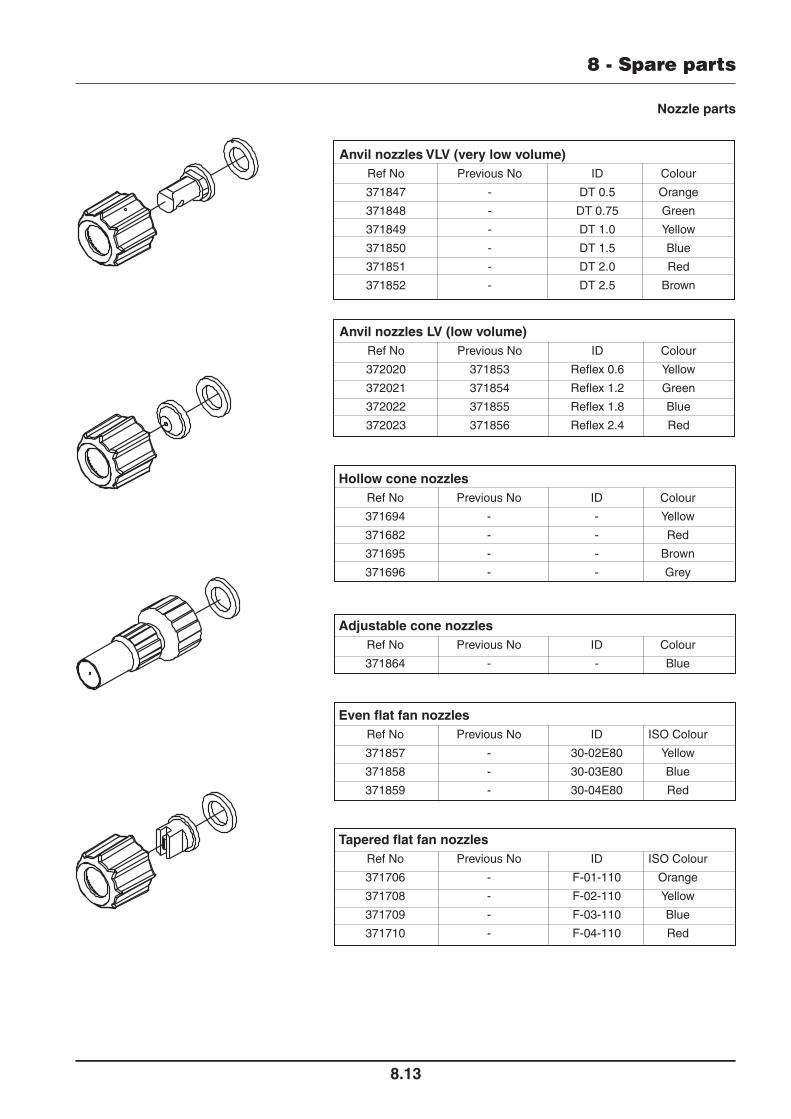
Nozzle parts
Anvil nozzles LV (low volume) Ref No Previous No ID Colour
372020 371853 Reflex 0.6 Yellow
372021 371854 Reflex 1.2 Green
372022 371855 Reflex 1.8 Blue
372023 371856 Reflex 2.4 Red
Anvil nozzles VLV (very low volume) Ref No Previous No ID Colour
371847 - DT 0.5 Orange
371848 - DT 0.75 Green
371849 - DT 1.0 Yellow
371850 - DT 1.5 Blue
371851 - DT 2.0 Red
371852 - DT 2.5 Brown
Hollow cone nozzles Ref No Previous No ID Colour
371694 - - Yellow
371682 - - Red
371695 - - Brown
371696 - - Grey
Adjustable cone nozzles Ref No Previous No ID Colour
371864 - - Blue
Even flat fan nozzles Ref No Previous No ID ISO Colour
371857 - 30-02E80 Yellow
371858 - 30-03E80 Blue
371859 - 30-04E80 Red
Tapered flat fan nozzles Ref No Previous No ID ISO Colour
371706 - F-01-110 Orange
371708 - F-02-110 Yellow
371709 - F-03-110 Blue
371710 - F-04-110 Red

8 - Spare parts
8.14
Decals for 12 volt sprayer range
89104304
89100804
(177mm x 110mm) 976157
(294mm x 182mm) 976183
WARNINGAgricultural chemicals can be dangerous.Improper selection or use can seriously injurepersons, animals, plants, soil or otherproperty.BE SAFE: Select the right chemical for the job.Handle it with care. Follow the instructions onthe container label and of the equipmentmanufacturer. Always wear protectiveclothing.
89100804
READ OPERATOR'S MANUAL BEFORE USE.