Embed Size (px)
Citation preview

METEC METAL TECHNOLOGY INC. Reserve all right
Original Holder
Attachment for
C480 / C992
Owner’s Manual
And Parts List
Model #:
4160-SA
2744-SA
Mechanical Sweeper
Mechanical Sweeper Rev. 01 - February 2013
Owner’s Manual and Parts List
Page 1 of 48 Holder tractors Inc. www.holdertractors.ca
4160-SA Series
Mechanical sweeper
For HOLDER tractor
C 480, C992
2744-SA Series
Hydrolic drive sweeper
For HOLDER tractor
C 480, C992

Mechanical Sweeper Rev. 01 - February 2013
Owner’s Manual and Parts List
Page 2 of 48 Holder tractors Inc. www.holdertractors.ca
Table of Contents
READ AND UNDERSTAND THIS MANUAL COMPLETELY .................................................................................................. 3
READ ALL SAFETY INFORMATION IN THIS MANUAL. ...................................................................................................... 4
INSTALLATION ................................................................................................................................................................. 9
PROPER PRESSURE ON THE SWEEPER BRISTLES. .......................................................................................................... 28
RUNNING THE MECHANICAL SWEEPER ........................................................................................................................ 29
OPERATING TIPS ............................................................................................................................................................ 30
MAINTENANCE .............................................................................................................................................................. 31
SCHEDULE...................................................................................................................................................................... 32
ALIGNING SPROCKETS ................................................................................................................................................... 33
PROPER CHAIN TENTION ............................................................................................................................................... 34
GREASING LOCATION .................................................................................................................................................... 35
BRUSH ASSEMBLY ......................................................................................................................................................... 36
US to METRIC - METRIC to US CONVERSION ................................................................................................................ 38
BOLT TORQUE SPECIFICATIONS .................................................................................................................................... 39
OPTIONAL EQUIPMENT ................................................................................................................................................. 40
SWEEPER PARTS LIST..................................................................................................................................................... 41
PRODUCT WARRANTY REGISTRATION CARD ................................................................................................................ 47

Mechanical Sweeper Rev. 01 - February 2013
Owner’s Manual and Parts List
Page 3 of 48 Holder tractors Inc. www.holdertractors.ca
READ AND UNDERSTAND THIS MANUAL COMPLETELY
Some parts & guards have been removed for clarity purposes.
This product has been designed and fabricated to deliver efficient and reliable service provided it is operated safely and maintained in accordance with the instructions in this manual.
This manual is provided as a guideline to the owner and operator(s) for the operation and maintenance of this attachment. The manual is based on the attachment at the time of manufacture and does not cover any after-market modifications.
The owner and operator(s) should ensure that they have read and have a clear understanding of this manual as well as the operator’s manual for the tractor to which this attachment will be mounted. The efficient and safe operation of the unit depends on this understanding. Safety recommendations should be adhered to by all users of this attachment.
Refer to the model and serial number when requesting parts or service. Enter your serial number and date of purchase in the space provided below.
MODEL NUMBER: ____________________________________________________
SERIAL NUMBER: ____________________________________________________
DATE OF PURCHASE: ____________________________________________________

Mechanical Sweeper Rev. 01 - February 2013
Owner’s Manual and Parts List
Page 4 of 48 Holder tractors Inc. www.holdertractors.ca
READ ALL SAFETY INFORMATION IN THIS MANUAL. General safety practices are listed on the safety information pages and specific safety information is located throughout this manual.
SAFETY SYMBOL
This is the safety alert symbol. It is used in the manual and on safety labels to remind operators and repair personnel of important safety practices and procedures. When you see this symbol, become alert – your safety is involved. Safety is no accident!
HAZARD DEFINITIONS
Three classifications of hazard are listed in this manual and on safety labels. In order of seriousness from the greatest to the least, they are:
DANGER:
Indicates an immediately hazardous situation which, if not avoided, will result in death or serious injury.
WARNING:
Indicates a potentially hazardous situation which, if not avoided, could result in death or serious injury.
CAUTION:
Indicates a potentially hazardous situation which, if not avoided, may result in minor or moderate injury.
IMPORTANT: Indicates that equipment or property damage could result if instructions are not followed.
NOTE: Gives helpful information.

Mechanical Sweeper Rev. 01 - February 2013
Owner’s Manual and Parts List
Page 5 of 48 Holder tractors Inc. www.holdertractors.ca
SAFETY GUIDELINES:
1. Prior to operation, the equipment should be thoroughly inspected and every operator should have a clear understanding of the potential dangers inherent with the operation of this equipment.
2. Children and equipment do not mix; do not allow children to play on or around equipment and work area.
3. Use extreme care and caution when approaching areas such as blind corners, playgrounds, and other busy or sight-obstructed spots.
4. Ensure all guards and covers are securely fastened and that all safety equipment and lights are functioning properly.
5. Wear appropriate clothing that cannot become entangled in the equipment’s moving parts or accidentally snag a control lever.
6. Some attachments increase the swing radius of an articulated tractor, be sure of where your machine ends.
7. Before starting tractor, ensure that hydraulic and PTO drives are disengaged. 8. Do not attempt to service, repair or adjust any attachment on a machine that is running. 9. Do not modify or alter the attachment without consulting your dealer.
SAFETY BEFORE OPERATION:
1. Read and understand manuals for the tractor and attachments to be used. Know how to operate all controls and to stop the equipment quickly.
2. Ensure that all attachments are properly installed and fastened before operation. 3. Check the fittings and fasteners on tractor and implement. Perform any repairs or adjustments
before starting machine. 4. Ensure that all safety decals are clearly visible and legible. 5. Ensure that PTO and hydraulic drives are disengaged before starting engine. 6. Tractors and attachments must be properly lubricated and adjusted at the beginning of each shift
and at specified intervals thereafter. 7. Before beginning sweeping operations, clear the area to be swept of all large objects that may
damage the equipment or may be damaged by the machine.
SAFETY DURING OPERATION:
1. In order to avoid accidents, be familiar with the area of operation such as blind spots, driveway crossings, road crossings and other dangerous areas.
2. Do not carry passengers unless the machine is equipped for them. 3. Wear seat belt, eye and hearing protection while operating equipment. Eye wear is particularly
important as the sweeper raises a lot of dust and debris which can be blown back into the operator’s face.
4. Keep hands, feet, hair and loose clothing away from all moving parts of the engine, drive lines, chains, sweeper brush and other moving parts.
5. All chain covers and shields must be in place before operating equipment. 6. Never sweep towards people, pets, buildings, vehicles or other objects that can damaged by flying
debris. Always use the most effective brush speed for the operating conditions. 7. Yield to pedestrians in your work area, bring the tractor to a complete halt and turn off the
attachment until it is safe to resume operations.

Mechanical Sweeper Rev. 01 - February 2013
Owner’s Manual and Parts List
Page 6 of 48 Holder tractors Inc. www.holdertractors.ca
8. If you must leave the tractor during operation, disengage PTO/hydraulic drives, bring the machine to a complete stop, lower the implement, shut off the engine, set the parking brake and remove the ignition key.
9. Always operate the tractor within the manufacturer’s recommended safety guidelines. Operate the tractor at speeds compatible with the working conditions.
10. Do not run against curbs, rocks or other obstructions with the sweeper.

Mechanical Sweeper Rev. 01 - February 2013
Owner’s Manual and Parts List
Page 7 of 48 Holder tractors Inc. www.holdertractors.ca
Important – All signs & labels need to be visible at all time. Clean and or replace damage signs and labels. Your spare parts department should have these in stock. Location of labels PTO Drive Shown
Figure 1
Label part location Part name
1. Caution label 2. Danger label 3. Danger Drive shaft & PTO label 4. Identification plate of the sweeper.
Part numbers are in the part list section

Mechanical Sweeper Rev. 01 - February 2013
Owner’s Manual and Parts List
Page 8 of 48 Holder tractors Inc. www.holdertractors.ca
Representation of labels
Figure 2
Figure 3 Figure 4

Mechanical Sweeper Rev. 01 - February 2013
Owner’s Manual and Parts List
Page 9 of 48 Holder tractors Inc. www.holdertractors.ca
INSTALLATION
Figure 5
Here you see the Holder Sweeper Model 4160-SA 60” shown in the storage position. The storage legs should always be used so as to prevent the bristles from bending. Always install the PTO shaft, once lubricated, onto the sweeper first, using the keyway stock, and set screws. Check for loose hardware, proper drive chain tension, gearbox oil level and any damage prior to usage.

Mechanical Sweeper Rev. 01 - February 2013
Owner’s Manual and Parts List
Page 10 of 48 Holder tractors Inc. www.holdertractors.ca
Figure 6
Holder Sweeper model 2744-SA: Here you see the Holder Sweeper Model 2744-SA shown in Attached to our tractor. The storage legs should always be used so as to prevent the bristles from bending. Check for loose hardware and any damage prior to usage.

Mechanical Sweeper Rev. 01 - February 2013
Owner’s Manual and Parts List
Page 11 of 48 Holder tractors Inc. www.holdertractors.ca
Figure 7
Installing the sweeper attachment. Part A: 1. One hole should protrude, giving correct arm length. 2. Approach with the tractor lift arm lowered. 3. Stop to verify that lift hooks are adjusted to the correct width and are aligned with lift pins. 4. Use a ¾” or 19mm wrench to loosen wedge bolt. Slide lift hook to according width, retightening wedge
bolt. See Fig.07 5. Both hooks should be placed with equal distance from the end of slide.
Mechanical Sweeper Rev. 01 - February 2013
Owner’s Manual and Parts List
Page 12 of 48 Holder tractors Inc. www.holdertractors.ca
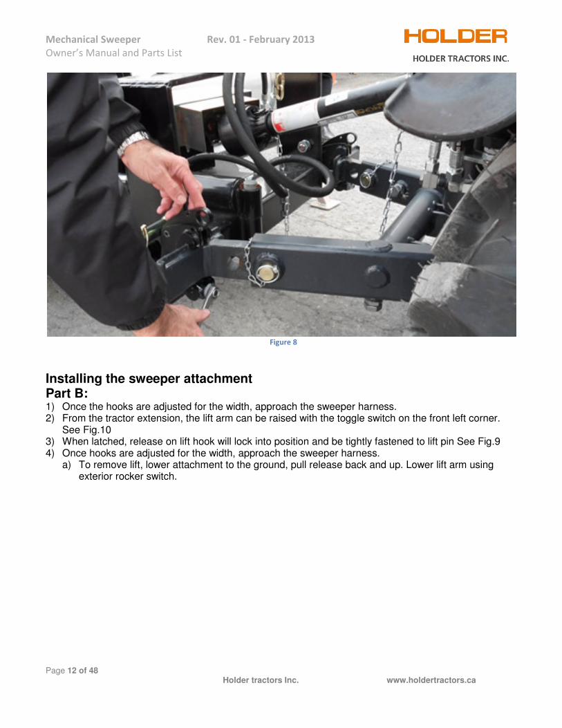
Figure 8
Installing the sweeper attachment Part B: 1) Once the hooks are adjusted for the width, approach the sweeper harness. 2) From the tractor extension, the lift arm can be raised with the toggle switch on the front left corner.
See Fig.10 3) When latched, release on lift hook will lock into position and be tightly fastened to lift pin See Fig.9 4) Once hooks are adjusted for the width, approach the sweeper harness.
a) To remove lift, lower attachment to the ground, pull release back and up. Lower lift arm using exterior rocker switch.

Mechanical Sweeper Rev. 01 - February 2013
Owner’s Manual and Parts List
Page 13 of 48 Holder tractors Inc. www.holdertractors.ca
Figure 9
Figure 10

Mechanical Sweeper Rev. 01 - February 2013
Owner’s Manual and Parts List
Page 14 of 48 Holder tractors Inc. www.holdertractors.ca
Figure 11
Figure 12
The safety chain of the drive shaft cover should be attached to the bottom main frame. PTO Sweeper only.

Mechanical Sweeper Rev. 01 - February 2013
Owner’s Manual and Parts List
Page 15 of 48 Holder tractors Inc. www.holdertractors.ca
Figure 13
Attaching PTO Shaft. (Grease before attaching) With the tractor engine off, the shaft can be raised and compressed to fit through lift arm assembly and brought up to the tractor PTO. Rotate the shaft to line-up splines manually. Once aligned, pull back on the spring loaded collar and slide the shaft onto the tractor PTO. Release the collar and continue to slide the shaft until it clicks into position. The collar will spring out. Attaches the PTO cover safety chain through the top hole of the top link location on the C480 tractor, and in the bottom hole of the C992 tractor.
Mechanical Sweeper Rev. 01 - February 2013
Owner’s Manual and Parts List
Page 16 of 48 Holder tractors Inc. www.holdertractors.ca
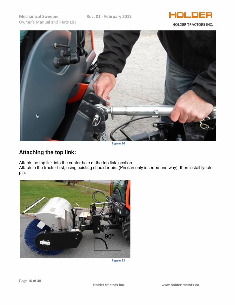
Figure 14
Attaching the top link: Attach the top link into the center hole of the top link location. Attach to the tractor first, using existing shoulder pin. (Pin can only inserted one way), then install lynch pin.
Figure 15

Mechanical Sweeper Rev. 01 - February 2013
Owner’s Manual and Parts List
Page 17 of 48 Holder tractors Inc. www.holdertractors.ca
Figure 16
Using the top link adjusting pin, extend the top link until the sweeper end fits into the harness hole. Insert the pin through the harness hole and top link end hole all the way through. Install lynch pin to secure. Adjust top link length so sweeper harness is perpendicular to the ground. Fig. 16
Mechanical Sweeper Rev. 01 - February 2013
Owner’s Manual and Parts List
Page 18 of 48 Holder tractors Inc. www.holdertractors.ca
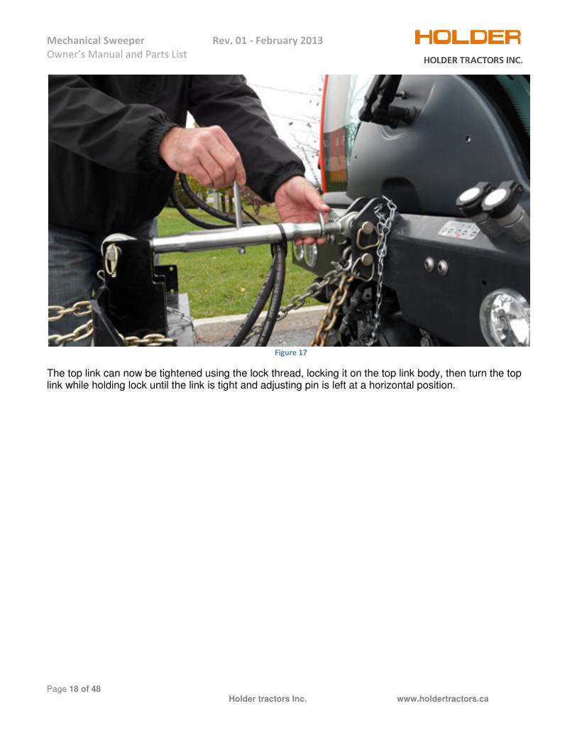
Figure 17
The top link can now be tightened using the lock thread, locking it on the top link body, then turn the top link while holding lock until the link is tight and adjusting pin is left at a horizontal position.

Mechanical Sweeper Rev. 01 - February 2013
Owner’s Manual and Parts List
Page 19 of 48 Holder tractors Inc. www.holdertractors.ca
Figure 18
Figure 19
Attaching hydraulic hoses: On the control panel, push the GREEN button until the light comes on. This will put the GREEN coupler located at the front of the tractor into float mode. This will facilitate fitting the male coupler to the female.

Mechanical Sweeper Rev. 01 - February 2013
Owner’s Manual and Parts List
Page 20 of 48 Holder tractors Inc. www.holdertractors.ca
The GREEN couplers are preferred as no buttons will be required to be pushed on the joystick when swinging the sweeper.
Mechanical Sweeper Rev. 01 - February 2013
Owner’s Manual and Parts List
Page 21 of 48 Holder tractors Inc. www.holdertractors.ca
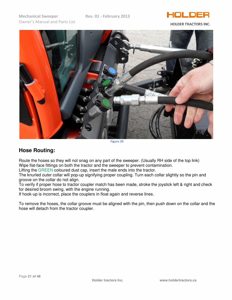
Figure 20
Hose Routing: Route the hoses so they will not snag on any part of the sweeper. (Usually RH side of the top link) Wipe flat-face fittings on both the tractor and the sweeper to prevent contamination. Lifting the GREEN coloured dust cap, insert the male ends into the tractor. The knurled outer collar will pop-up signifying proper coupling. Turn each collar slightly so the pin and groove on the collar do not align. To verify if proper hose to tractor coupler match has been made, stroke the joystick left & right and check for desired broom swing, with the engine running. If hook-up is incorrect, place the couplers in float again and reverse lines. To remove the hoses, the collar groove must be aligned with the pin, then push down on the collar and the hose will detach from the tractor coupler.

Mechanical Sweeper Rev. 01 - February 2013
Owner’s Manual and Parts List
Page 22 of 48 Holder tractors Inc. www.holdertractors.ca
Figure 21
Note: Cylinder hose farthest away will pull cylinder shaft in, swinging the sweeper to the right. This hose should be inserted into RH GREEN coupler. Closest cylinder hose will swing sweeper to the left, therefore hose should be inserted into LH GREEN coupler.
Mechanical Sweeper Rev. 01 - February 2013
Owner’s Manual and Parts List
Page 23 of 48 Holder tractors Inc. www.holdertractors.ca
Figure 22
Figure 23
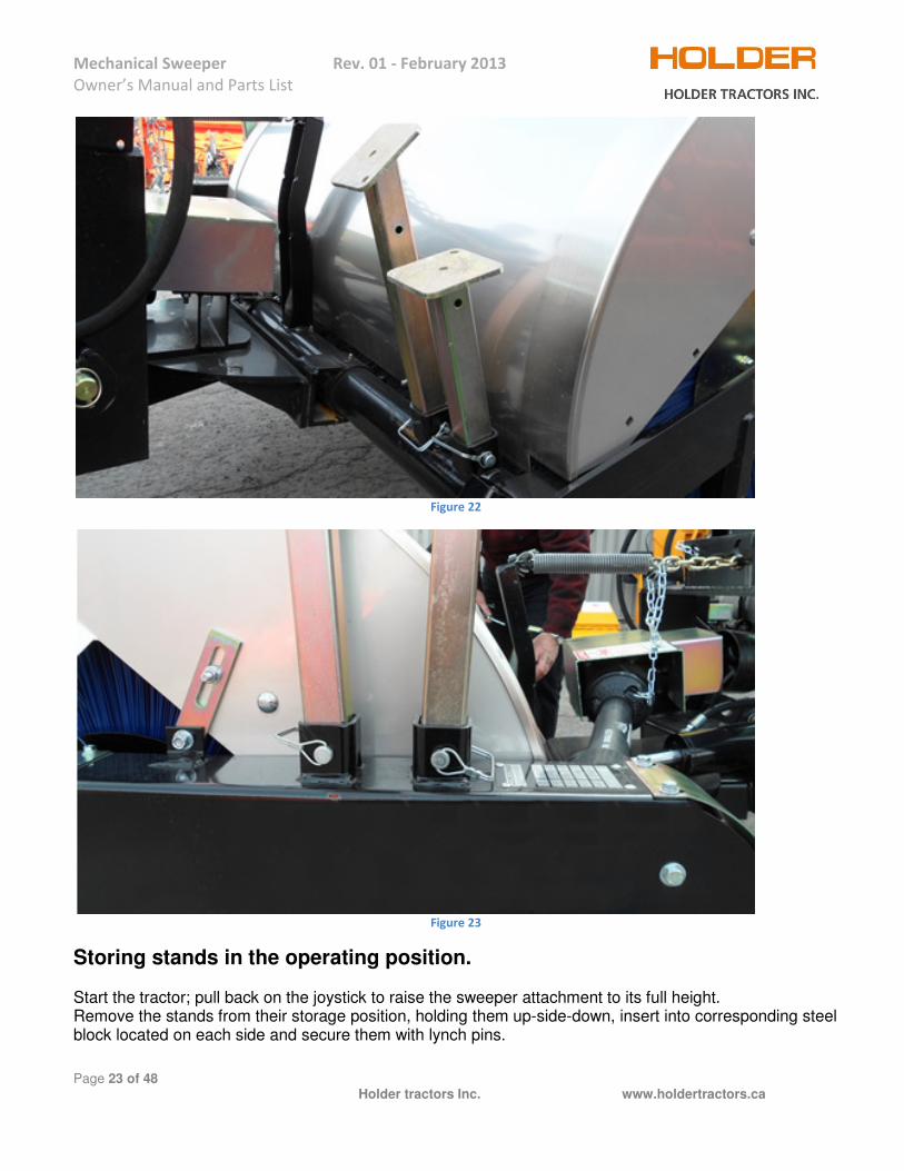
Storing stands in the operating position. Start the tractor; pull back on the joystick to raise the sweeper attachment to its full height. Remove the stands from their storage position, holding them up-side-down, insert into corresponding steel block located on each side and secure them with lynch pins.

Mechanical Sweeper Rev. 01 - February 2013
Owner’s Manual and Parts List
Page 24 of 48 Holder tractors Inc. www.holdertractors.ca
Figure 24
Attaching drop chain on model C480 tractor. Insert a shoulder pin into the lowest hole on the tractor top link location, then insert the clevis attached to the chain, then push the pin the rest of the way through the second tractor top link. Secure with a lynch pin. Chain will spread out when sweeper harness is lowered. Note: 1) Drop chains in the lower hole. 2) Top link in the center hole. 3) Cover safety chain in the top hole.

Mechanical Sweeper Rev. 01 - February 2013
Owner’s Manual and Parts List
Page 25 of 48 Holder tractors Inc. www.holdertractors.ca
Figure 25
Attaching drop chain on model C992 tractor. Insert a long steel pin provided into the second hole from the bottom on the tractor top link location, then insert the clevis attached to the chain, then push the steel pin the rest of the way through the second hole from the bottom tractor top link. Secure with a lynch pin. Chain will spread out when sweeper harness is lowered. Note: 1) Drop chain in the second hole from the bottom. 2) Top link block is in second from the top hole. 3) Cover safety chain is in lowest hole.
Mechanical Sweeper Rev. 01 - February 2013
Owner’s Manual and Parts List
Page 26 of 48 Holder tractors Inc. www.holdertractors.ca
Figure 26
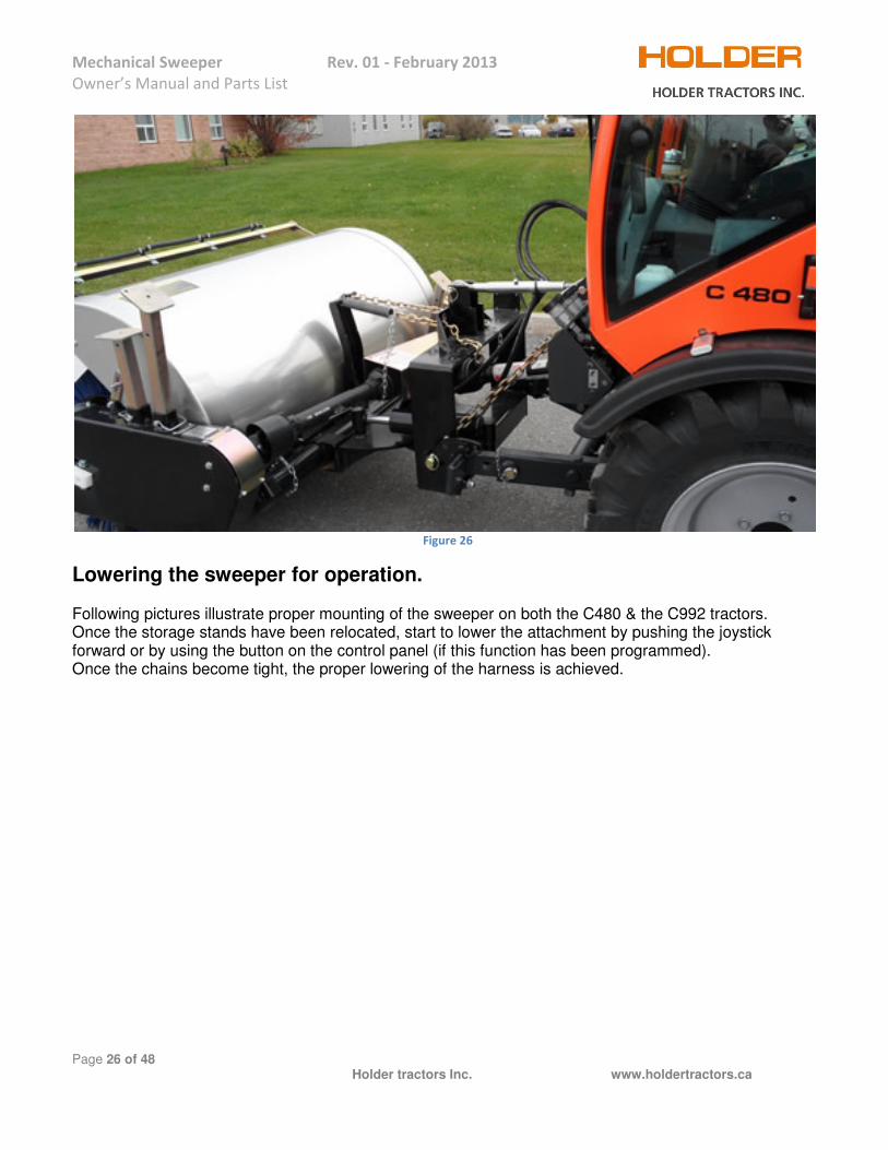
Lowering the sweeper for operation. Following pictures illustrate proper mounting of the sweeper on both the C480 & the C992 tractors. Once the storage stands have been relocated, start to lower the attachment by pushing the joystick forward or by using the button on the control panel (if this function has been programmed). Once the chains become tight, the proper lowering of the harness is achieved.
Mechanical Sweeper Rev. 01 - February 2013
Owner’s Manual and Parts List
Page 27 of 48 Holder tractors Inc. www.holdertractors.ca
Figure 27
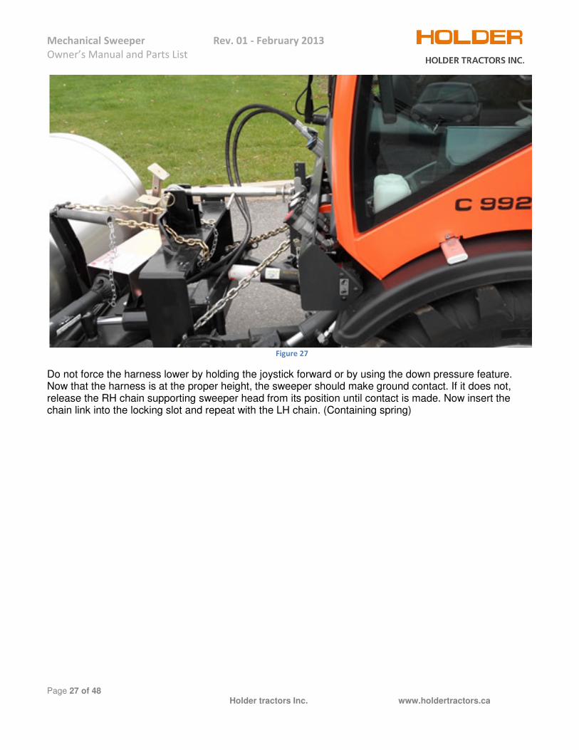
Do not force the harness lower by holding the joystick forward or by using the down pressure feature. Now that the harness is at the proper height, the sweeper should make ground contact. If it does not, release the RH chain supporting sweeper head from its position until contact is made. Now insert the chain link into the locking slot and repeat with the LH chain. (Containing spring)

Mechanical Sweeper Rev. 01 - February 2013
Owner’s Manual and Parts List
Page 28 of 48 Holder tractors Inc. www.holdertractors.ca
PROPER PRESSURE ON THE SWEEPER BRISTLES.
Figure 28
Rotate the sweeper brush for a few seconds. Disengage the PTO and raise the sweeper. Fig.28 indicates the proper amount of pressure the sweeper applies to the surface. 4” to 6” (10 to 15 cm) is Ideal for proper amount of “flicking” action without excessive wear. Adjust links until this pattern is reached. This pattern will need to be verified as the bristle wears down over time, the chains will need adjusting as well.

Mechanical Sweeper Rev. 01 - February 2013
Owner’s Manual and Parts List
Page 29 of 48 Holder tractors Inc. www.holdertractors.ca
RUNNING THE MECHANICAL SWEEPER Place the program switch in either 3 or 4. Turn the speed dial down to “0.” With the sweeper slightly above the ground, engage the PTO. Raise the engine rpm to about 2200 rpm, in order to reach a maximum of 540 PTO rpm, by using the hand throttle located on the right side of the cab.
• Sweeper can be operated at less than 540 PTO rpm but not less than 1500 engine rpm, as the
electronic drive system is inoperable at engine speed less than 1500 rpm. Once the desired engine speed is achieved, set the tractor directional lever to forward and slowly turn the speed dial. Lower the sweeper until drop chains is tight. Set the ground speed dial according to condition & desired result. Angling of the broom is achieved by stoking the joystick left or right.
• Should you need to come to a sudden stop, the inching pedal can be depressed or speed dial turned to “0”

Mechanical Sweeper Rev. 01 - February 2013
Owner’s Manual and Parts List
Page 30 of 48 Holder tractors Inc. www.holdertractors.ca
OPERATING TIPS
• Always engage the PTO at Idle speed, and then bring the rpm to its proper operating speed. o Maximum of 540 PTO rpm.
• Always disengage PTO when tractor engine is at Idle.
• Do not attempt to move piles of material with the sweeper, as it’s not a blade.
• Windrow debris away from pedestrians, vehicles, steps etc... o Swing the sweeper so it’s facing straight until you have cleared the area, then you can
continue to windrow.
• Due to the sweeper design, the left hand side is heavier due to drive mechanising. o To prevent (coning) of the bristles, the oscillation cylinder can be used to apply a slight
amount of pressure on the right side of the sweeper.

Mechanical Sweeper Rev. 01 - February 2013
Owner’s Manual and Parts List
Page 31 of 48 Holder tractors Inc. www.holdertractors.ca
MAINTENANCE MAINTENANCE RECORD Use this log to record maintenance performed on your unit.
Date Maintenance Performed Performed by Comments

Mechanical Sweeper Rev. 01 - February 2013
Owner’s Manual and Parts List
Page 32 of 48 Holder tractors Inc. www.holdertractors.ca
SCHEDULE PROCEDURE SCHEDULE Before
each use
After every 40
hours
Before each
season
Refer to tractor manual
When needed
Constant Velocity (CV) - Lubricate with high-quality grease. √
Drive chain
Check for adjustment. √
√
Remove chain from sprocket and soak in motor oil.
√
√
To loosen stiff links, soak in penetrating oil; bend back & forth. Replace chain if this does not work.
√
Hardware - Tighten √ √
Lubrication Points – Lubricate with high-quality grease. √
Spring-Chain assembly – Adjust. √
√
Sprockets – Check alignment. √
√
Universal
Joints
Check for wear. Tighten set screws & jam nut. √
Lubricate with high-quality grease.
√
Gear Box
Use SAE 90 Oil. The first oil change should be affected after the first 50 working hours. Subsequent changes should take place after 500 – 800 hours or at least once a year in order to avoid sludge deposit.
√
Oil level √
Hydraulic Motor
Verify that the motor attachment is secure, And there are no leeks. √

Mechanical Sweeper Rev. 01 - February 2013
Owner’s Manual and Parts List
Page 33 of 48 Holder tractors Inc. www.holdertractors.ca
ALIGNING SPROCKETS
Practice for Aligning Sprockets • Sprockets should be replaced or aligned whenever new chains are installed. This will have a significant effect on chain life. • Particular care should be paid to ensure that the shafts are installed parallel and that sprockets are aligned. Both can be accomplished quickly with a laser alignment tool. • Maximum misalignment for slow moving application (under 10 ft/sec) is 0.2% of the center distance. For faster moving running drives, misalignment should not exceed 0.1% of the center distance.
Identifying misalignment Where the misalignment exceeds the specified value or if there is no support in the case of vertical chain drives, the following can be observed. • The inner links of the chain will interfere with the sprocket teeth resulting in continuous knocking of the inner link plates, which are eventually pushed outwards until they contact the outer link plates and reduce the freedom of movement. • Vibration will also be observed which will further accelerate the wear of both chain and sprocket.
Figure 29

Mechanical Sweeper Rev. 01 - February 2013
Owner’s Manual and Parts List
Page 34 of 48 Holder tractors Inc. www.holdertractors.ca
PROPER CHAIN TENTION Guidelines: Proper tension of a roller chain is best achieved by applying 5% of the actual load seen by the chain. If this is unknown, applying 1% of the chain breaking load may be substituted.
Other methods for standard drive Layouts Chain slack on horizontal drivers should be 2-3%of the total center distance of the sprockets. This distance is slack measured in one direction as shown below.
Recommendations: 1. Measure chain slack using guidelines above. 2. If slack is excessive, increase tension by moving sprockets center distance. 3. When slack exceeds ability to tension replace chain and sprockets.
Figure 30

Mechanical Sweeper Rev. 01 - February 2013
Owner’s Manual and Parts List
Page 35 of 48 Holder tractors Inc. www.holdertractors.ca
GREASING LOCATION
Figure 31
Grease Nipple (fitting) location
1. Fittings on both side of the sweeper on the pillow block for 4160-SA & 2744-SA. 2. Fittings on both sides on the pivoting shaft for 4160-SA & 2744-SA. 3. Fittings on both ends of the drive shaft for 4160-SA. 4. Fittings on the both ends of the PTO shaft for 4160-SA.
Greasing should be done after every 8 hrs of work.

Mechanical Sweeper Rev. 01 - February 2013
Owner’s Manual and Parts List
Page 36 of 48 Holder tractors Inc. www.holdertractors.ca
BRUSH ASSEMBLY
Figure 32

Mechanical Sweeper Rev. 01 - February 2013
Owner’s Manual and Parts List
Page 37 of 48 Holder tractors Inc. www.holdertractors.ca
PS. It is highly recommended to change all of the brushes, and not just a few.
Please follow all of the steps of installation instructions!
1. Check your core. All drive bars should be inspected for indentations or excessive wear.
2. Safety. Stand core upright with support for safety, when installing wafer sections.
3. Installation. Begin installing the wafer on the core, ensuring the drive pins of each wafer section lock the wafer over one of the wafer core’s drive bar.
4. Build a balanced broom. Install consecutive convoluted wafers rotating each 180°, (6 o’clock and 12 o’clock positions). The result should be a snug fit. This installation provides a broom for normal sweeping conditions. We do have an application for maximum broom density for cores with 4 drive bars. This is achieved by installing consecutive convoluted wafers rotating each 90°. This application does require the purchase of more wafers.
5. Reinstall core on the sweeper. To lower and move a refilled core, attach supports directly to the metal sweeper core. Do not apply force, pressure or lift to any part of the wafer or filament during the core installation onto the sweeper.
6. Tips and techniques. Remember, a broom sweeps with the tips of the filament, not the sides. DO NOT MOP! Keep broom level to optimize surface coverage and extend broom life. Do not exceed proper down pressure which will limit the “flick action” of the filament. Maintain steady ground speed to prevent unnecessary stress on the broom core.
7. Replace worn wafers. When wafers reach one half of the original outside diameter.
Mechanical Sweeper Rev. 01 - February 2013
Owner’s Manual and Parts List
Page 38 of 48 Holder tractors Inc. www.holdertractors.ca
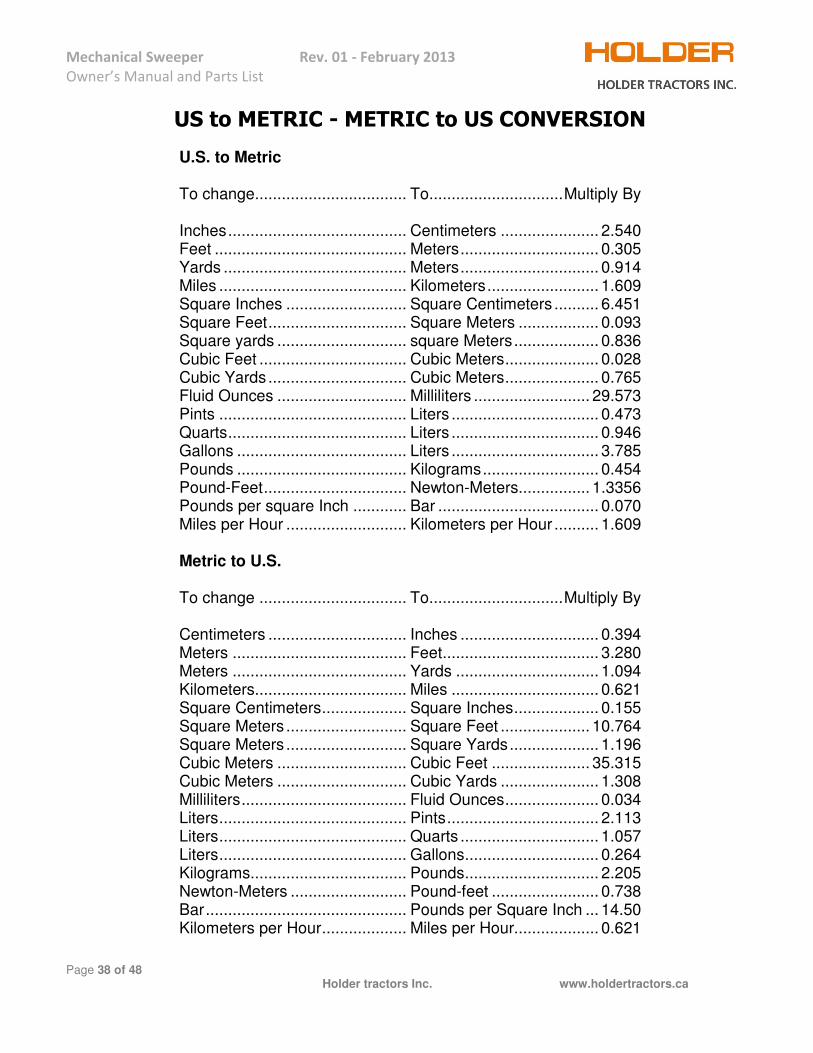
US to METRIC - METRIC to US CONVERSION
U.S. to Metric To change.................................. To .............................. Multiply By Inches ........................................ Centimeters ...................... 2.540 Feet ........................................... Meters ............................... 0.305 Yards ......................................... Meters ............................... 0.914 Miles .......................................... Kilometers ......................... 1.609 Square Inches ........................... Square Centimeters .......... 6.451 Square Feet ............................... Square Meters .................. 0.093 Square yards ............................. square Meters ................... 0.836 Cubic Feet ................................. Cubic Meters ..................... 0.028 Cubic Yards ............................... Cubic Meters ..................... 0.765 Fluid Ounces ............................. Milliliters .......................... 29.573 Pints .......................................... Liters ................................. 0.473 Quarts ........................................ Liters ................................. 0.946 Gallons ...................................... Liters ................................. 3.785 Pounds ...................................... Kilograms .......................... 0.454 Pound-Feet ................................ Newton-Meters................ 1.3356 Pounds per square Inch ............ Bar .................................... 0.070 Miles per Hour ........................... Kilometers per Hour .......... 1.609 Metric to U.S. To change ................................. To .............................. Multiply By Centimeters ............................... Inches ............................... 0.394 Meters ....................................... Feet ................................... 3.280 Meters ....................................... Yards ................................ 1.094 Kilometers .................................. Miles ................................. 0.621 Square Centimeters ................... Square Inches ................... 0.155 Square Meters ........................... Square Feet .................... 10.764 Square Meters ........................... Square Yards .................... 1.196 Cubic Meters ............................. Cubic Feet ...................... 35.315 Cubic Meters ............................. Cubic Yards ...................... 1.308 Milliliters ..................................... Fluid Ounces ..................... 0.034 Liters .......................................... Pints .................................. 2.113 Liters .......................................... Quarts ............................... 1.057 Liters .......................................... Gallons .............................. 0.264 Kilograms................................... Pounds .............................. 2.205 Newton-Meters .......................... Pound-feet ........................ 0.738 Bar ............................................. Pounds per Square Inch ... 14.50 Kilometers per Hour ................... Miles per Hour................... 0.621

Mechanical Sweeper Rev. 01 - February 2013
Owner’s Manual and Parts List
Page 39 of 48 Holder tractors Inc. www.holdertractors.ca
BOLT TORQUE SPECIFICATIONS Bolt Coarse Grade 5 Grade 8
SizeThread*
Inches per Inch Torque in foot pounds
1/4 20 10 14 5/16 18 19 29 3/8 16 33 47 7/16 14 54 78 1/2 13 78 119 9/16 12 114 169 5/8 11 154 230 3/4 10 257 380 7/8 9 382 600 1 8 587 700 1-1/8 7 794 1430 1-1/4 7 1105 1975 1-3/8 6 1500 2650 1-1/2 6 1775 3200
To determine the torque for a fine-thread bolt, increase rating by 9%.
All torques are measured on dry standard bolts.

Mechanical Sweeper Rev. 01
Owner’s Manual and Parts List
Page 40 of 48
OPTIONAL EQUIPMENT Adjustable caster wheels for the adjustment of the broom height.
The kit consists of the adjusting mechanism with the caster and the bracket that you weld on the frame.The instruction on where to weld the bracket comes with the kit. The installation takes but a few moments to install.
Rev. 01 - February 2013
Holder tractors Inc. www.holdertractors.ca
OPTIONAL EQUIPMENT
Adjustable caster wheels for the adjustment of the broom height.
Figure 33
The kit consists of the adjusting mechanism with the caster and the bracket that you weld on the frame.The instruction on where to weld the bracket comes with the kit. The installation takes but a few moments
www.holdertractors.ca
The kit consists of the adjusting mechanism with the caster and the bracket that you weld on the frame. The instruction on where to weld the bracket comes with the kit. The installation takes but a few moments

Mechanical Sweeper Rev. 01 - February 2013
Owner’s Manual and Parts List
Page 41 of 48 Holder tractors Inc. www.holdertractors.ca
SWEEPER PARTS LIST
Figure 34
Figure 35

Mechanical Sweeper Rev. 01 - February 2013
Owner’s Manual and Parts List
Page 42 of 48 Holder tractors Inc. www.holdertractors.ca
Figure 36
Mechanical Sweeper Rev. 01 - February 2013
Owner’s Manual and Parts List
Page 43 of 48 Holder tractors Inc. www.holdertractors.ca
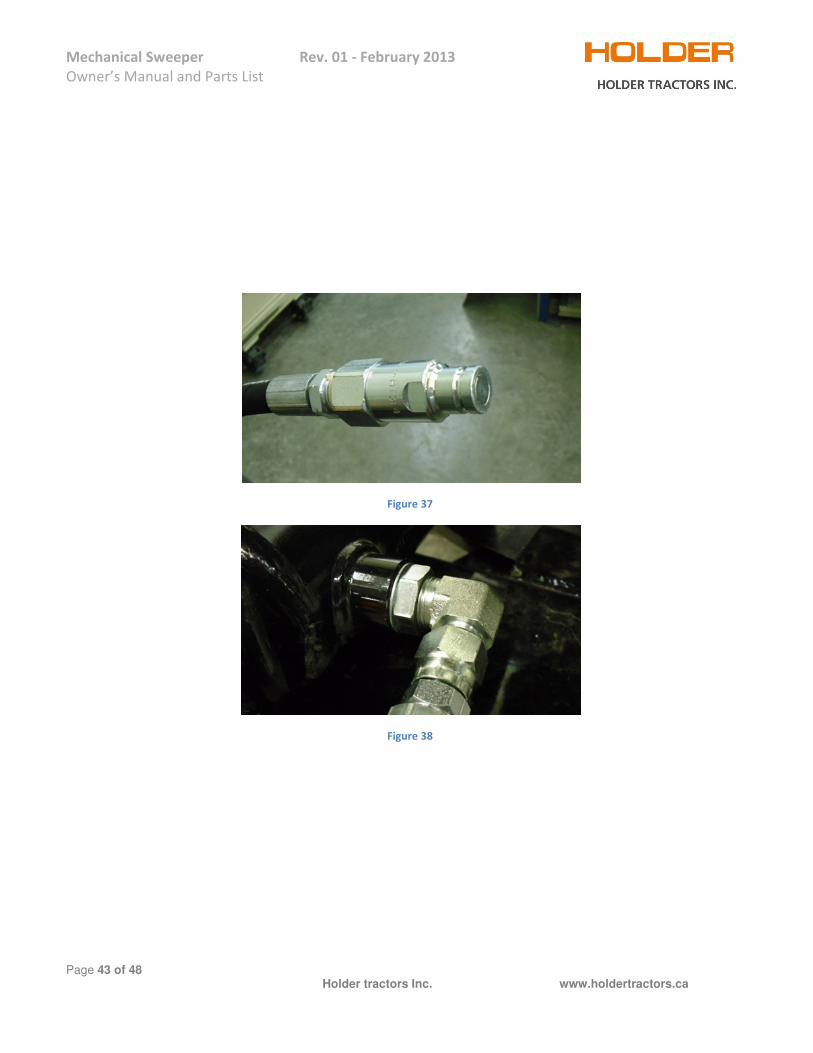
Figure 37
Figure 38

Mechanical Sweeper Rev. 01 - February 2013
Owner’s Manual and Parts List
Page 44 of 48 Holder tractors Inc. www.holdertractors.ca
Figure 39
Figure 40
Mechanical Sweeper Rev. 01 - February 2013
Owner’s Manual and Parts List
Page 45 of 48 Holder tractors Inc. www.holdertractors.ca
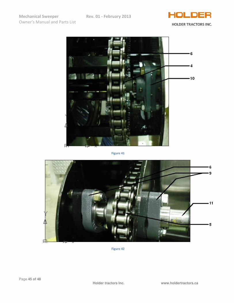
Figure 41
Figure 42
Mechanical Sweeper Rev. 01 - February 2013
Owner’s Manual and Parts List
Page 46 of 48 Holder tractors Inc. www.holdertractors.ca
Note: Top link and Block, Safety chain and Pin are not included with the sweeper. # -- Description ---------------------------------------------------------- Fig --- Part # ------------------------- Qty. 1---- Brush wafer ------------------------------------------------------------- Fig.35 --- SA-001 (Refer to page 41) 1 Set 2---- Brush core ------------------------------------------------------- (not shown) --- SA-002 ------------------------- 1 3---- Brush core end plates ------------------------------------------------ Fig.40 --- SA-003 ------------------------- 1Pair 4---- Driven sprocket -------------------------------------------------------- Fig.41 --- SA-004 ------------------------- 1 5---- Drive sprocket ---------------------------------------------------------- Fig.42 --- SA-005 ------------------------- 1 6---- Drive chain ------------------------------------------------------- Fig.41 & 42 --- O/L: # 60 heavy duty -------- 1 7---- Chain guard – Front -------------------------------------------------- Fig.35 --- SA-007 ------------------------- 1 8---- Chain guard – Rear --------------------------------------------------- Fig.35 --- SA-008 ------------------------- 1 9---- Two bolt flange bearing ---------------------------------------------- Fig.42 --- SA-009 ------------------------- 2 10 -- Four bolt flange bearing ------------------------------------- Fig. 41 & 42 --- SA-010 ------------------------- 2 11 -- Drive chain input shaft – 1” ----------------------------------------- Fig.42 --- SA-011 ------------------------- 1 12 -- Brush cowling support ---------------------------------------- Fig.34 & 35 --- SA-012 ------------------------- 1 13 -- Brush cowling --------------------------------------------------- Fig.34 & 35 --- SA-013 ------------------------- 1 14 -- Rear leg ---------------------------------------------------------- Fig.34 & 35 --- SA-014 ------------------------- 2 15 -- Front leg ---------------------------------------------------------- Fig.34 & 35 --- SA-015 ------------------------- 2 16 -- Top link pin ------------------------------------------------------ Fig.34 & 35 --- SA-016 ------------------------- 1
16a Lynch pin for top link pin Fig.35- -------------------------------------- O/L: --- ν 5/16” x 2 ¾” ----------------- 2 17 -- Shaft key stock (not shown) ------------------------------------------- O/L: --- ¼” x 1 ¾” ---------------------- 1 18 -- Hydraulic cylinder ---------------------------------------------------- Fig.39 --- SA-018 ------------------------- 1 19 -- Elbow fitting for SA-021 ---------------------------------- Fig.38 & 39 O/L --- O-ring boss 10x9/16-18 male ----- ------------------------------------------------------------------------------------ --- - JIC 90° Elbow -------------- 2 20 -- Straight fitting for SA-021 --------------------------------------Fig.37O/L: --- Flat face nipple 3/8x1/2 - -- 2 21 -- Hydraulic hose for SA-018 -------------------------------------------------- --- SA-021 ------------------------- 2 22 -- Tension spring for brush head assembly ------------------------ Fig.34 --- SA-022 ------------------------- 1 22a Chain for brush head assembly ---------------------------- Fig.34 – O/L --- Grade 70 (14 Links) --------- 1 22b Chain for brush head assembly ---------------------------- Fig.35 – O/L --- Grade 70 (24 Links) --------- 1 23 -- PTO shaft broom side for model # 4160-SA -------------------- Fig.39 --- SA-023 ------------------------- 1 24 -- PTO shaft tractor side for model # 4160-SA (not shown) ----------- --- SA-024 ------------------------- 1 25 -- Gear box ---------------------------------------------------------------- Fig.39 --- SA-025 ------------------------- 1 26 -- Gear box cover -------------------------------------------------------- Fig.39 --- SA-026 ------------------------- 1 27 -- Hydraulic motor -------------------------------------------------------- Fig.36 --- SA-027 ------------------------- 1 28 -- Brush head frame assembly --------------------------------- Fig.34 & 35 --- SA-028 ------------------------- 1 29 -- Hitch pin ---------------------------------------------------------- Fig.34 & 35 --- SA-029 ------------------------- 2
29a Lynch pin for hitch pin (on some models only) --------- Fig.10 – O/L --- ν 5/16” x 2 ¾” ----------------- 2 30 -- Wear block protector ------------------------------------------ Fig.34 & 35 --- SA-030 ------------------------- 2 31 -- Wet kit including 4 nozzle ------------------------------------ Fig.34 & 35 --- SA-031 ------------------------- 1 32 -- Caution label ---------------------------------------------------------- Fig.02 --- SA-032 ------------------------- 1 33 -- Danger Moving part hazard ----------------------------------------- Fig.03 --- SA-033 ------------------------- 1 34 -- Danger PTO label ----------------------------------------------------- Fig.04 --- SA-034 ------------------------- 1 35 -- Owner’s manual --------------------------------------------------------------- --- SA-035 ------------------------- 1 36 -- Motor hose assembly ------------------------------------------------ Fig.36 --- SA-036 ------------------------- 2 37 -- Broom caster kit ------------------------------------------------------- Fig.33 --- SA-037 ------------------------- 2

Mechanical Sweeper Rev. 01 - February 2013
Owner’s Manual and Parts List
Page 47 of 48 Holder tractors Inc. www.holdertractors.ca
PRODUCT WARRANTY REGISTRATION CARD
Please detach along the dotted line and mail and keep Warranty for your records
Product: Sweeper Vario plough Angle plough Snow blower Hydro sweeper Rotary snow plough Model number__________________________ Serial Number_______________________________ Name: _________________________________________________________________________ Address: _________________________________________________________________________ City: ______________________Province/State _______________Postal/zip code____________ Tel No: ____________________________________ Email: ________________________________ Date of Purchase __________________________ New Replacement ……………………………………………………………………………………………………………………………
Warranty: This product is warranted against defect of material and workmanship for the period of one year, against any and all part of this attachment. The procedure to obtain repair under the warranty is to contact the Holder Company of North America.
The warranty is void if any part of the equipment is altered or modified in ways. Any changes made will be done without notification.

Mechanical Sweeper Rev. 01 - February 2013
Owner’s Manual and Parts List
Page 48 of 48 Holder tractors Inc. www.holdertractors.ca
Holder Tractors Inc. 100 Bay Street, Embrun ON, Canada K0A 1W1 January, 01 2013 Tel: 613-443-3200 Fax: 613-443-9600 Revision 1 Email: [email protected]