Embed Size (px)
Citation preview

SWEDISH EOD AND DEMINING Date SWEDEC designation
CENTRE 4 Nov 2008 13345:60511 Page 1 (30)
()
Mailing Address Visiting Address Telephone Fax E-mail, Internet
Box 1003 SE-575 28 EKSJÖ SWEDEN
+46 381 180 00
+46 381 184 14
[email protected] www.swedec.mil.se
FREELAND 3000 Test and Evaluation August 2008
Patrik Blomander, SWEDEC

SWEDISH EOD AND DEMINING Date SWEDEC designation
CENTRE 4 Nov 2008 13345:60511 Page 2 (30)
Abstract
A test of the Freeland 3000 was performed in Sweden by SWEDEC in August 2008. Performance and survivability tests were done according to the European Committee for Standardisation (CEN) Workshop Agreement ”CEN Workshop Agreement 15044; Test and Evaluation of Demining Machines”, available at the international Test and Evaluation Website (www.itep.ws). Executive summary
During the week of August 20-28, 2008, the Freeland 3000 was tested at the SWEDEC facilities near Eksjö, Sweden. This trial was planned and facilitated almost entirely by SWEDEC. The methodology specified in CEN Workshop Agreement ”CEN Workshop Agreement 15044; Test and Evaluation of Demining Machines” was used. It started with a performance test and ended with a survivability test. These tests make up the content of this report. The machine is operated from the cabin on the machine. The weight is 18.7 tonnes and fits into what is normally regarded as medium-flail class of machines (6-20 tonnes). The Freeland 3000 triggered or neutralized 450 mines of 450 mines - 100 % of the target mines used in these trials. The results in each lane were varying between 44 up to 50 broken or triggered mines. The penetration of the witnessboards during the tests was showing a small variation (chapter 6).The variation on some witnessboards shown different depth, the depth shows a different up to 10 cm right to left. This could depend on that the flail head is not in level. The machine demonstrated the ability to penetrate well beyond the depth required to reach the deepest targets. In all but the most difficult soil, a smooth uniform cut across the whole width of the machine was observed. The survivability test went well. The machine was not driving across the anti-tank mine the Swedish m/41-47 placed at surface. The machine was not driving across the mine because of that the machine had not done the operator survivability test. The mine was placed in front of the flail and was remotely detonated. The machine suffered no damage from the mine. No tools were missing. The machine could operate again after five minutes. Freeland 3000 had done a Pre-Test Assessment at SWEDEC, this during August 18-19 2008.The Pre-Test Assessment report is available at ITEP.

SWEDISH EOD AND DEMINING Date SWEDEC designation
CENTRE 4 Nov 2008 13345:60511 Page 3 (30)
Table of contents
Abstract................................................................................................................. 2 Executive summary .............................................................................................. 2 Table of contents .................................................................................................. 3 1. Introduction ...................................................................................................... 4 2 Machine Description.......................................................................................... 5
2.1 FREELAND 3000 Mine Clearance System.......................................... 5 3. Trial Description............................................................................................... 6
3.1 Test Team.............................................................................................. 6 3.2 Trial Conditions .................................................................................... 6
4. Test Results....................................................................................................... 6 4.1 Results against mine targets .................................................................. 6 4.2 Tabular Data and Explanations ............................................................. 7
4.2.1 Debris and Scatter..................................................................... 8 4.3 Depth and Consistency of Penetration .................................................. 9
4.3.1 General...................................................................................... 9 5. Survivability Test ........................................................................................... 18
5.1 Trial Descriptions............................................................................... 18 5.2 Anti-Tank Mine................................................................................... 18 5.3 Test Methods....................................................................................... 19 5.4 Test Results ......................................................................................... 19
6 Test Facilities and Tools.................................................................................. 21 6.1 Soil Compaction.................................................................................. 22 6.3 Test Targets......................................................................................... 23 6.4 Mine Target Burial .............................................................................. 25 6.5 Mine Target Level of Damage ............................................................ 26 6.6 Witness Boards.................................................................................... 28 6.7 Test Methods....................................................................................... 30
Annex A – Test Data Sheets
SWEDISH EOD AND DEMINING Date SWEDEC designation
CENTRE 4 Nov 2008 13345:60511 Page 4 (30)
1. Introduction
During the week of August 18-28, 2008, the Freeland 3000 was tested at the SWEDEC facilities near Eksjö, Sweden. Agreed tests to be carried out according to CEN Workshop Agreement 15044:2004 were Performance Test and Survivability test. These tests were planned and facilitated almost entirely by SWEDEC, and was requested and partially funded by Complete Demining AB, the manufacturer of the machine. An overall description of the test facilities, the test targets and the test methods are given in chapter 6. This information is relevant to any machine tested at this site.

SWEDISH EOD AND DEMINING Date SWEDEC designation
CENTRE 4 Nov 2008 13345:60511 Page 5 (30)
2 Machine Description
2.1 FREELAND 3000 Mine Clearance System
The FREELAND 3000 ground clearing flail is operated from the cabin on the machine. The Freeland 3000 is built on an ROTTNE F9 and the engine for the flail is an DUETZ double turbo. The manufacturer Complete Demining AB had built Freeland 3000.
Figure 1. Freeland 3000 Figure 2. Flail Head
Figure 3. Freeland Flail Head with tool. Figure 4. Flail engine.

SWEDISH EOD AND DEMINING Date SWEDEC designation
CENTRE 4 Nov 2008 13345:60511 Page 6 (30)
3. Trial Description
3.1 Test Team
Capt Patrik Blomander, SWEDEC (test leader) Bo Fernholm, SWEDEC Anders Bredelius, SWEDEC Joakim Engblom, SWEDEC 3.2 Trial Conditions
A complete description of the test areas, the facilities and tools, and the test procedures can be found in chapter 6. Soil compaction levels (actual) can be found in the test data sheets in Annex A (Test protocol). To summarize, conditions1 for the Freelander 3000 test are indicated below: - Sand: 90% (1.8 kg/dm³) - Gravel: 94% (2.0 kg/dm³) - Topsoil: 85% (1.7 kg/dm³) Depths, number of mines and witness panels: - Depths tested in each soil: 0cm, 10cm and 15cm DOB (Depth Of Burial) - Number of test target mines at each depth: 50 - Witness panels included with each set of 50 targets: 3- one at the start, one at
the mid-point and one at the end of each test area. 4. Test Results
4.1 Results against mine targets
This section summarizes the performance of the machine. In addition to simply tabulating numbers, the data is given a statistical treatment as suggested by the CEN Workshop Agreement.
1 Soil compaction levels (intended)

SWEDISH EOD AND DEMINING Date SWEDEC designation
CENTRE 4 Nov 2008 13345:60511 Page 7 (30)
4.2 Tabular Data and Explanations
Table 1 shows the number of mines triggered, the number of mines with separated fuzes (neutralized), and the number of intact mines at each depth and in each soil condition. This table also indicates the number of untriggered fuzes which were found separated from their main charges. In total the machine drove over 450 mine targets, 50 mine targets at each depth. During each test, at least three people were responsible for counting fuze detonations. After the test was complete, any remaining fuzes would be sought using metal detectors. If the fuzes can’t be found right away additional steps can be taken - the soil will be turned over twice with a farm plough, once with a backhoe bucket and twice with an excavator bucket. During these tests there was no need to use any of the additional steps. Table 1. Mine targets triggered, separated fuzes and whole mines.
0 cm 10 cm 15 cm Triggered
Separated fuzes
Intact mines (live)
Triggered
Separated fuzes
Intact mines(live)
Triggered
Separated fuzes
Intact mines (live)
Sand
44/50
6
50/50
50/50
Gravel
47/50
3
1
50/50
50/50
Topsoil
50/50
49/50
1
50/50
1 One whole mine without fuze.

SWEDISH EOD AND DEMINING Date SWEDEC designation
CENTRE 4 Nov 2008 13345:60511 Page 8 (30)
The numbers are taken from the test protocol contained in the Annex A. This table combines detonated mines with those left damaged, non-functional. There were 50 targets in each test condition. 4.2.1 Debris and Scatter
When a demining machine (as the Freeland 3000) engages a mine target it may leave the mine in a number of different conditions. The target may be left intact and fully functional or it may be intact but damaged. It may be lightly damaged or completely broken apart. After each test in the series, the test lanes were searched as described above, and the materials of interest were assembled and inspected. These materials included fuzes, fuze components, intact mine targets, and mine bodies with most of or the entire (inert) main charge intact. The photos in figures 1-3 show the collected debris.
Figure 1, Sand 0 cm Figure 2, Gravel 0 cm
Figure 3, Top Soil 10 cm

SWEDISH EOD AND DEMINING Date SWEDEC designation
CENTRE 4 Nov 2008 13345:60511 Page 9 (30)
4.3 Depth and Consistency of Penetration
4.3.1 General
Fibreboards were used to measure the depth and consistency of penetration across the path of vehicle. Examples are shown in figure 4-12. Sand witness board: mine DOB surface 0 cm
Figure 4. Sand 1, 0 cm
Figure 5. Sand 2, 0 cm.
Figure 6. Sand 3, 0 cm. Comment: The first witness board had a penetration to 20cm, the left side of the witness board had not the same depth it could depend on that the board had been bend. The second and third board had a penetration to a depth of 25-30 cm.

SWEDISH EOD AND DEMINING Date SWEDEC designation
CENTRE 4 Nov 2008 13345:60511 Page 10 (30)
Sand witness board: mine DOB surface 10 cm
Figure 7. Sand 1,10 cm
Figure 8. Sand 2,10 cm
Figure 9. Sand 3,10 cm Comment: The first witness board had a penetration down to 30 cm. The second board showed penetration down to 25 cm and the third board down to 20 cm. The distant between the first board and the third board is 25 m and the difference in depth is up to 10 cm.

SWEDISH EOD AND DEMINING Date SWEDEC designation
CENTRE 4 Nov 2008 13345:60511 Page 11 (30)
Sand witness board: mine DOB surface 15 cm
Figure 10. Sand 1, 15 cm
Figure 11. Sand 2, 15 cm
Figure 12. Sand 3, 15 cm Comment: The first board had a straight penetration down to 20-25 cm but it is a different in depth from the right to the left side up to 10 cm. The second board showed penetration down to 20 cm and the third board down to 30 cm. The distains between the second and third board is not more than 12.5 m and the different in depth is up to 10 cm.

SWEDISH EOD AND DEMINING Date SWEDEC designation
CENTRE 4 Nov 2008 13345:60511 Page 12 (30)
Gravel witness board: mine DOB surface 0 cm.
Figure 13. Gravel 1, 0 cm
Figure 14. Gravel 2, 0 cm
Figure 15.Gravel 3, 0 cm Comment: The first board had a penetration down to 20 cm but it is a different in depth from the right to the left side up to 10 cm. The second board and the third board showed a penetration down to 20 cm but it is a different from the right to the left side on both boards up to 5 cm.

SWEDISH EOD AND DEMINING Date SWEDEC designation
CENTRE 4 Nov 2008 13345:60511 Page 13 (30)
Gravel witness board: mine DOB surface 10 cm.
Figure 16. Gravel 1, 10 cm
Figure 17. Gravel 2, 10 cm
Figure 18. Gravel 3, 10 cm Comment: The first board had a straight penetration down to 30 cm The second board and third board showed penetration down to 20 cm on right side and the down to 30 cm on the left side.

SWEDISH EOD AND DEMINING Date SWEDEC designation
CENTRE 4 Nov 2008 13345:60511 Page 14 (30)
Gravel witness board: mine DOB surface 15 cm.
Figure 19. Gravel 1, 15 cm
Figure 20. Gravel 2, 15 cm
Figure 21. Gravel 3, 15 cm Comment: The first board had a straight penetration down to 25 cm. The second board showed a penetration down to 20 cm on the right side and down to 30 cm on the left side. The third board showed a straight penetration down to 25 cm.
SWEDISH EOD AND DEMINING Date SWEDEC designation
CENTRE 4 Nov 2008 13345:60511 Page 15 (30)
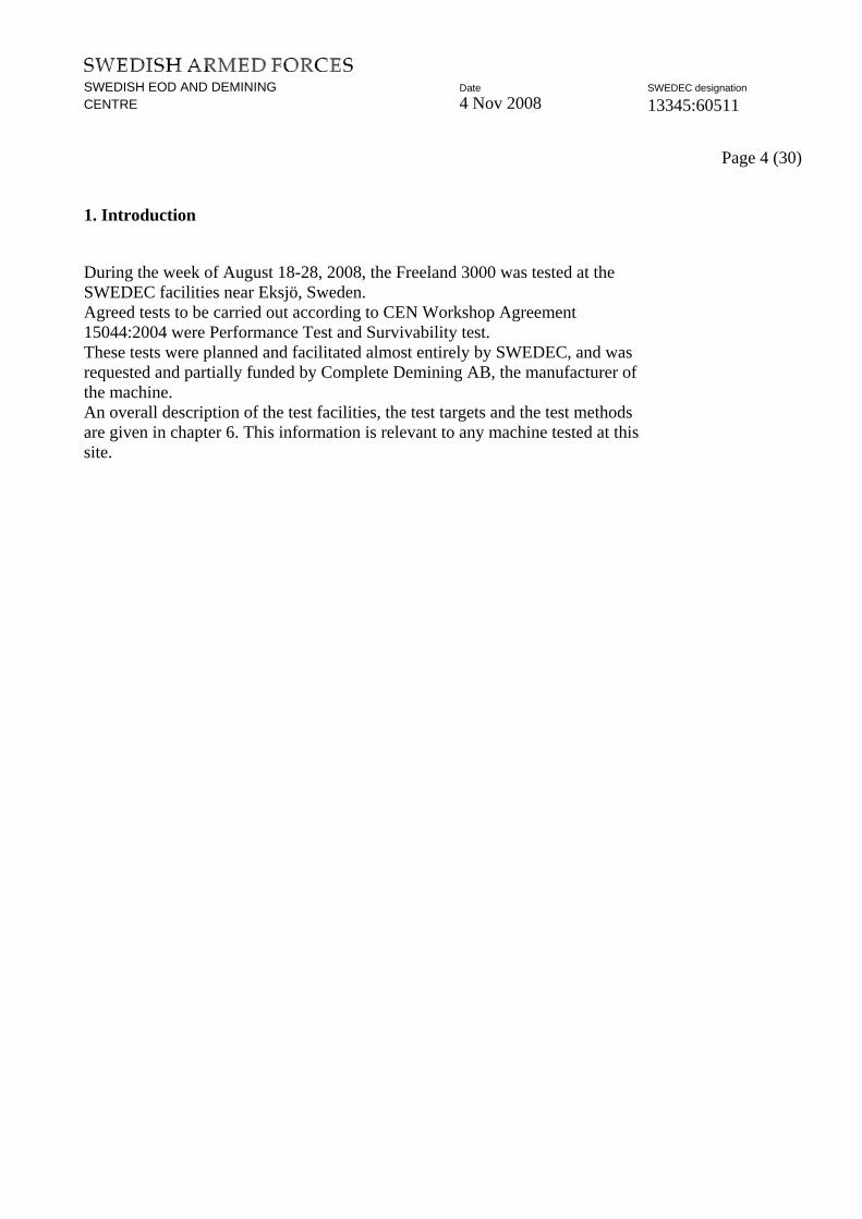
Topsoil witness board: mine DOB surface 0 cm.
Figure 22. 1, Topsoil 1, 0 cm
Figure 23. 1, Topsoil 2, 0 cm
Figure 24. 1, Topsoil 3, 0 cm Comment: The first board had a penetration down to 30 cm. The second board and third board showed a penetration down to 25 cm.

SWEDISH EOD AND DEMINING Date SWEDEC designation
CENTRE 4 Nov 2008 13345:60511 Page 16 (30)
Topsoil witness board: mine DOB surface 10 cm:
Figure 25. 1, Topsoil 1,10 cm
Figure 26. 1, Topsoil 2,10 cm
Figure 27. 1, Topsoil 3,10 cm Comment: The first board had a penetration down to 20 cm on the right side and down to 30 cm on the left side. The second board and third board showed penetration down to 30 cm, the boards had been destroyed it was not possible to find all peaces from the board.

SWEDISH EOD AND DEMINING Date SWEDEC designation
CENTRE 4 Nov 2008 13345:60511 Page 17 (30)
Topsoil witness board: DOB surface on mine15 cm:
Figure 28. 1, Topsoil 1,15 cm
Figure 29. 1, Topsoil 2,15 cm
Figure 30. 1, Topsoil 3,15 cm Comment: All boards showed a straight penetration down to 30 cm. The boards had been destroyed it was not possible to find all peaces from the board. Summary witness board Fourteen of the witnessboards are showing an inclination from the right to the left. This could depend on that the flail aggregate not is in balance, it could deepen on the weight on one side of the aggregate. This problem is necessary to analyse.

SWEDISH EOD AND DEMINING Date SWEDEC designation
CENTRE 4 Nov 2008 13345:60511 Page 18 (30)
5. Survivability Test
The CEN Workshop Agreement methodology calls for survivability testing using antipersonnel and/or antitank mines. Anti-personnel mines are required to test all machines for susceptibility to damage from normal operational conditions created by triggering anti-personnel mines. Machines which are advertised for use against anti-tank mines are also required to be tested against anti-tank mine charges to ensure that they are able to absorb anti-tank mine blasts without undue levels of damage. 5.1 Trial Descriptions
The test facilities for survivability testing near Eksjö have been used to test different types of equipment in recent years. The blast range includes a gravel bed 5 m wide and 35 m long. The bed contains compacted 018 fraction gravel. The lane is located at an angle of about 45 degrees from the safe house. One camera were used during the test - High Speed Video Camera from the roof of the safety house. 5.2 Anti-Tank Mine
According to the CEN Workshop Agreement the mine should have a net explosive weight of 8 kg. The anti-tank mine used in this trial was the standard Swedish m/41-47B mine. The total weight of the m/41-47 mine is 6 kg and it contains 5 kg of TNT. The mine was boosted with 2.25 kg of plastic explosive (PETN), which corresponds to 3 kg TNT:

SWEDISH EOD AND DEMINING Date SWEDEC designation
CENTRE 4 Nov 2008 13345:60511 Page 19 (30)
5.3 Test Methods
Following preparation of the test lane and installation of the mines as described above, the machine was prepared for a test run. The machine was positioned about 8 metres in front of the start of the test lane to allow the driver to get the machine operating in a consistent stable manner prior to the start of the lane. Then the mine was placed just in front of the flail. The camera was started and all personnel went into the safe house. The machine was left in run with engine and flail. The mine was triggered remotely. The result from the detonation was first examined visually. When the test team was sure that no major damage or leaks had occurred, the FREELAND 3000 was started and all functions were tested. 5.4 Test Results
The 8 kg detonations had no effect on the machine. The machine had no problem to continue to work after these tests. According to CWA the machine is not needed to drive over the mine, but if the flail is triggered the mine it will be more damage on the flail head.

SWEDISH EOD AND DEMINING Date SWEDEC designation
CENTRE 4 Nov 2008 13345:60511 Page 20 (30)
Figures from the survivability test.
Figure 31: Placed AT mine m/41-47 in front of flail. Figure32, Placed AT mine m/41-47 in front of flail
Figure 33, AT-mine m/41-47 ready to triggered Figure 34, After detonation
Figure 35, After detonation Figure 36,After detonation.
SWEDISH EOD AND DEMINING Date SWEDEC designation
CENTRE 4 Nov 2008 13345:60511 Page 21 (30)
6 Test Facilities and Tools
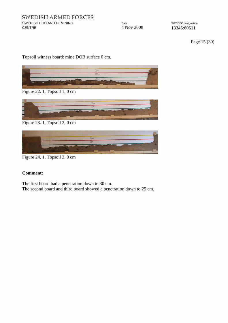
The test facilities at Norra Kulla, near Eksjö, have been used to test various types of equipment in recent years. The site has three soil environments specifically for performance tests. Parallel lanes 5 m wide and 100 m long provide compacted sand, compacted gravel and compacted topsoil. The sand and gravel lanes are easily replicated almost anywhere. As the characteristics of topsoil may vary from one location to the next, data from the topsoil lane may not be quite as repeatable. The soil in each test lane is prepared as follows. Prior to a test the soil is loosened with ordinary agricultural or construction equipment, and then compacted using the vibratory compacter as shown in Figure A-1. The soil compaction and moisture content are monitored until the compaction reaches a defined level for that soil type. Compaction and moisture content are measured using the CPN International model MC-3 Portable.

SWEDISH EOD AND DEMINING Date SWEDEC designation
CENTRE 4 Nov 2008 13345:60511 Page 22 (30)
6.1 Soil Compaction
Ideally the soil would be compacted to virtually 100%, or its theoretical maximum level of compaction. This is very difficult to achieve and depends on the moisture content of the soil. Based on the results of soil analyses conducted for SWEDEC, the compaction levels shown below were selected to allow testing over a range of soil moisture contents, and are reasonable and practical approximations of well compacted soil. · Sand: 90% (1.8 kg/dm
3)
· Gravel: 94% (2.0 kg/dm3)
· Topsoil: 85% (1.7 kg/dm3)
An example of a soil analysis for the topsoil is shown in Figure A-3. In this Swedish language chart, the horizontal axis refers to the moisture content (by weight), while the vertical axis shows the density, with a maximum occurring at 2.024 kg/dm
3 . A 95% compaction level (approximately 1.9 kg/dm
3) can only be
achieved with soil moisture contents between 6% and 12%; this might restrict testing if the moisture content were out of range on a given day. By comparison, compacting the topsoil to approximately 1.7 kg/dm
3 results in the soil reaching
85% of its theoretical maximum compaction. For the topsoil this is a useful target since it can be achieved without undue difficulty, and also because it is achievable over a wide range of moisture contents up to 18% or greater. Similar analyses were done to select the compaction levels for the sand and gravel areas. Target compaction levels for the three soils were:
Figure A 3

SWEDISH EOD AND DEMINING Date SWEDEC designation
CENTRE 4 Nov 2008 13345:60511 Page 23 (30)
6.2 Soil Particle Size Distribution Samples from the sand, gravel and topsoil areas were analyzed to determine particle size distribution, with Figure A-4 showing the results.
6.3 Test Targets
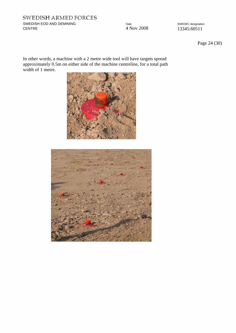
The test targets used in this trial were the standard SWEDEC mine surrogates shown in Figure A-5 and Figure A-6. The targets make use of live fuzes from the m/49 anti-personnel mine installed in inert, plaster-filled plastic bodies. These targets closely replicate many typical small antipersonnel land mines, which a machine might be expected to encounter. For the trial, 50 targets are buried at each depth, in each soil. Based on three depths in each soil type, this translates to 450 individual mine targets for a complete trial. To simplify the test procedures and data collection, each test comprises 50 targets, all at a single depth. Once that test has been completed, another 50 targets are placed at a different depth or in a different soil. The targets are located approximately 0.5 m apart to minimize the effects of soil disturbance from one target to another. They are laid in a path whose width is approximately 50% of the width of the machine working tool.
SWEDISH EOD AND DEMINING Date SWEDEC designation
CENTRE 4 Nov 2008 13345:60511 Page 24 (30)
In other words, a machine with a 2 metre wide tool will have targets spread approximately 0.5m on either side of the machine centreline, for a total path width of 1 metre.

SWEDISH EOD AND DEMINING Date SWEDEC designation
CENTRE 4 Nov 2008 13345:60511 Page 25 (30)
6.4 Mine Target Burial
In all cases, the mines are buried as shown in Figure A-7. The depth of burial (DOB) is measured from the top surface of the mine (not the top surface of the fuze), to the ground surface. Hence, a burial depth of 0 cm is illustrated in Figure A-5, above. To minimize soil disturbance, the tool shown in Figure A-8 was used to pull out a soil core just slightly larger than the mine body. The live fuzes are installed moments prior to the beginning of the test.
DOB – Subsurface DOB – Surf
Figure 7-8

SWEDISH EOD AND DEMINING Date SWEDEC designation
CENTRE 4 Nov 2008 13345:60511 Page 26 (30)
6.5 Mine Target Level of Damage
In accordance with the CEN workshop agreement, the results of the tests against mine targets were evaluated as follows.
Live, undamaged - Targets in this condition have not been damaged in any way, and remain fully functional.
Damaged, functional - Targets in this condition have been damaged by the machine but remain functional. This could include mines which have had part of the main explosive charge broken away, but where the fuze/initiation train remains attached to the remaining explosive material. Alternatively it could be the fuze which has sustained damage, but remains functional and able to detonate the mine.
Damaged, non-functional - Targets in this condition have not been triggered, but have been broken apart to the point where they can no longer function. This may be as simple as having removed an intact, functional fuze from an intact mine body or it may be a complete mechanical shredding of all components of the mine and fuze. Figure A-10 shows three example of this condition. From left to right, they include (i) a broken fuze torn from the main charge, (ii) an intact fuze torn from the main charge, and (iii) an intact main charge without a fuze. While not explicitly required, data was also recorded to indicate non-triggered fuzes found separated from their respective mine bodies after each trial. Examples are seen in Figure A-11, in which the top row shows intact functional targets missed by a machine. The second row shows fuzes separated from their mine bodies and fuzes still attached to the upper parts of the mine bodies but separated from what would, in a real mine, be the main explosive charge. The bottom row shows the lower bodies of targets which were broken apart without triggering the fuze and where the bulk of the plaster (the main charge in a real mine) remains intact.
Triggered - Mines in this category have been triggered by the machine. Since real mine fuzes are used in this trial, it is simple a matter of counting the detonations as the machine progresses. Figure A-12, captured from trial video records, shows a mine target being triggered by a machine. Just ahead of the smoke from the fuze, part of the red casing can be seen being expelled from the area.

SWEDISH EOD AND DEMINING Date SWEDEC designation
CENTRE 4 Nov 2008 13345:60511 Page 27 (30)

SWEDISH EOD AND DEMINING Date SWEDEC designation
CENTRE 4 Nov 2008 13345:60511 Page 28 (30)
6.6 Witness Boards
Along with the mine targets, witness boards are installed at three locations across each lane. At the start, middle and end of each test area, 3mm thick, 400 mm tall oil hardened (water resistant) fibreboards are installed across the full width of the flail head. Buried flush with the surface as shown in Figure A-13, the boards act as witness panels to record the depth of penetration of the tiller/flail hammers. This technique does not record the force with which the hammers strike, but it does give a clear, unambiguous indication of depth of penetration. Figure A-13 also show a typical example of the witness boards after a test when some of the neighbouring soil has been removed to expose the boards. A simple ‘pizza cutter’ tool was devised to make installation of the witness boards quick and easy without excessive disturbance of the surrounding soil. This tool, shown in Figure A-14, works very well in sand, topsoil and gravel.

SWEDISH EOD AND DEMINING Date SWEDEC designation
CENTRE 4 Nov 2008 13345:60511 Page 29 (30)

SWEDISH EOD AND DEMINING Date SWEDEC designation
CENTRE 4 Nov 2008 13345:60511 Page 30 (30)
6.7 Test Methods
Following preparation of the soil in the test lanes, and installation of the mine targets and witness boards as described above, the machine will be prepared for a test run. The machine will be positioned about 5-10 metres in front of the start of the test lane to allow the operator to get the machine operating in a consistent, stable manner prior to the start of the lane. Cameras will be started and personnel put in place to count detonations from the triggered fuzes. In most cases, a manufacturer’s representative will be used as a machine operator to ensure that the machine is operated in the most effective manner. When all is ready, the machine operator is signalled to begin, and the machine is driven through the test area containing 3 witness boards and 50 mine targets. With two or three people counting fuze detonations, the number of ‘triggered mines’ can easily be determined. Following the machine process, metal detectors will be used to locate any untriggered fuzes and also the metal washers in the plaster-filled bodies. In this way, the untriggered fuzes can be examined and ultimately discarded in a safe manner, and any untriggered or damaged mine casings can be inspected to determine the probable level of damage inflicted by the machine. Finally, with all untriggered fuzes removed from the area, the witness boards can be removed, labelled, and photographed. Along with the test lanes, the facilities at Norra Kulla provide office and administration space, warehouse and storage space, and basic workshop facilities.

SWEDISH EOD AND DEMINING Date Enclosure CENTRE 4 Nov 2008 Page 1 (9)
()
TEST PROTOCOL
Manufacturer Complete Demining AB
Date 2008-08-21
Weather Cloudy
Temperature 17oC
Test number 1:1
Deployment depth 0 cm
Test lane Sand
Rate of compaction 91%
Water content
Clearing depth 30-35 cm
Time/25 m 4.27 min
Clearing speed 337 m/h
Deployed: Triggered (detonated) Mechanically neutralised Live Damaged: Live: Total:
AP blast PMA2
AP bounce PROM1
AP frag PMR2A
AT blast TMM1
50 N/A N/A N/A
44
6
50
Machine type Freeland 3000
Comments: Six separeted fuzes. All fuzes were in function after test.
SWEDISH EOD AND DEMINING Date Enclosure CENTRE 4 Nov 2008 Page 2 (9)
()
TEST PROTOCOL
Manufacturer Complete Demining AB
Date 2008-08-21
Weather Cloudy
Temperature 17oC
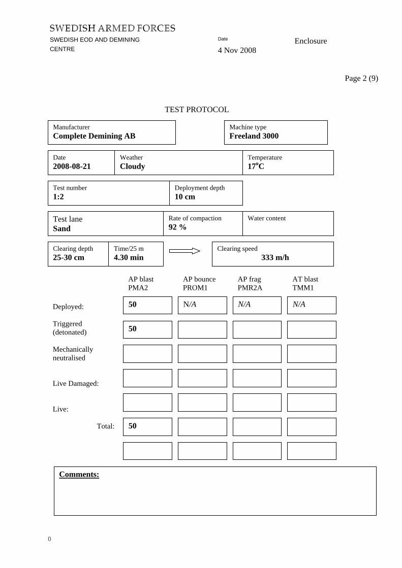
Test number 1:2
Deployment depth 10 cm
Test lane Sand
Rate of compaction 92 %
Water content
Clearing depth 25-30 cm
Time/25 m 4.30 min
Clearing speed 333 m/h
Deployed: Triggered (detonated) Mechanically neutralised Live Damaged: Live: Total:
AP blast PMA2
AP bounce PROM1
AP frag PMR2A
AT blast TMM1
50 N/A N/A N/A
50
50
Machine type Freeland 3000
Comments:

SWEDISH EOD AND DEMINING Date Enclosure CENTRE 4 Nov 2008 Page 3 (9)
()
TEST PROTOCOL
Manufacturer Complete Demining AB
Date 2008-08-21
Weather Cloudy
Temperature 17 oC
Test number 1:3
Deployment depth 15 cm
Test lane Sand
Rate of compaction 93 %
Water content
Clearing depth 20-30 cm
Time/25 m 4.45 min
Clearing speed 315 m/h
Deployed: Triggered (detonated) Mechanically neutralised Live Damaged: Live: Total:
AP blast PMA2
AP bounce PROM1
AP frag PMR2A
AT blast TMM1
50 N/A N/A N/A
50
50
Machine type Freeland 3000
Comments:

SWEDISH EOD AND DEMINING Date Enclosure CENTRE 4 Nov 2008 Page 4 (9)
TEST PROTOCOL
Manufacturer Complete Demining AB
Machine type Freealnd 3000
Date 2008-08-22
Weather Cloudy
Temperature 16oC
Test number 1:1
Deployment depth 0 cm
Test lane Gravel
Rate of compaction 95 %
Water content
Clearing depth 20 cm
Time/25 m 4.29 min
Clearing speed 335 m/h
AP blast PMA2
AP bounce PROM1
AP frag PMR2A
AT blast TMM1
Deployed: Triggered (detonated) Mechanically neutralised Live Damaged: Live: Total:
N/A N/A N/A 50
47
3
50
Comments: One whole mine without fuze. Three separated fuzes, one of this were cut. All fuzes was in function after test.

SWEDISH EOD AND DEMINING Date Enclosure CENTRE 4 Nov 2008 Page 5 (9)
()
TEST PROTOCOL
Manufacturer Complete Demining AB
Date 2008-08-22
Weather Sunny
Temperature 18oC
Test number 1:2
Deployment depth 10 cm
Test lane Gravel
Rate of compaction 95%
Water content
Clearing depth 30 cm
Time/25 m 4.27 min
Clearing speed 337 m/h
Deployed: Triggered (detonated) Mechanically neutralised Live Damaged: Live: Total:
AP blast PMA2
AP bounce PROM1
AP frag PMR2A
AT blast TMM1
50 N/A N/A N/A
50
50
Machine type Freeland 3000
Comments:

SWEDISH EOD AND DEMINING Date Enclosure CENTRE 4 Nov 2008 Page 6 (9)
()
TEST PROTOCOL
Manufacturer Complete Demining AB
Date 2008-05-05
Weather Cloudy
Temperature 17 C
Test number 1:3
Deployment depth 15cm
Test lane Gravel
Rate of compaction 94%
Water content
Clearing depth 25 cm
Time/25 m 4.22 min
Clearing speed 343 m/h
Deployed: Triggered (detonated) Mechanically Neutralised Live Damaged: Live: Total:
AP blast PMA2
AP bounce PROM1
AP frag PMR2A
AT blast TMM1
50 N/A N/A N/A
50
50
Machine type Freeland 3000
Comments:

SWEDISH EOD AND DEMINING Date Enclosure CENTRE 4 Nov 2008 Page 7 (9)
()
TEST PROTOCOL
Manufacturer Complete Demining AB
Date 2008-05-02
Weather Cloudy
Temperature 17oC
Test number 1:1
Deployment depth 0 cm
Test lane Topsoil
Rate of compaction 91%
Water content
Clearing depth 25-30 cm
Time/25 m 5.08 min
Clearing speed 292 m/h
Deployed: Triggered (detonated) Mechanically neutralised Live Damaged: Live: Total:
AP blast PMA2
AP bounce PROM1
AP frag PMR2A
AT blast TMM1
50 N/A N/A N/A
44
6
50
Machine type Freeland 3000
Comments: Six separeted fuzes. All fuzes were in function after test.

SWEDISH EOD AND DEMINING Date Enclosure CENTRE 4 Nov 2008 Page 8 (9)
()
TEST PROTOCOL
Manufacturer Complete Demining AB
Date 2008-08-21
Weather Sunny
Temperature 17oC
Test number 1:2
Deployment depth 10 cm
Test lane Topsoil
Rate of compaction 92 %
Water content
Clearing depth 30 cm
Time/25 m 5.28 min
Clearing speed 274 m/h
Deployed: Triggered (detonated) Mechanically neutralised Live Damaged: Live: Total:
AP blast PMA2
AP bounce PROM1
AP frag PMR2A
AT blast TMM1
50 N/A N/A N/A
50
50
Machine type Freeland 3000
Comments: One separated fuze was cut.

SWEDISH EOD AND DEMINING Date Enclosure CENTRE 4 Nov 2008 Page 9 (9)
()
TEST PROTOCOL
Manufacturer Complete Demining AB
Date 2008-05-05
Weather Sunny
Temperature 18 C
Test number 1:3
Deployment depth 15cm
Test lane Topsoil
Rate of compaction 94%
Water content
Clearing depth 30 cm
Time/25 m 5.07 min
Clearing speed 293 m/h
Deployed: Triggered (detonated) Mechanically Neutralised Live Damaged: Live: Total:
AP blast PMA2
AP bounce PROM1
AP frag PMR2A
AT blast TMM1
50 N/A N/A N/A
50
50
Machine type Freeland 3000
Comments:


![DDAS Accident Report · EOD/Survey Team arrived at the site at 08:40hrs, established a Command Post (CP) and conducted a communications check with [1st commercial demining group]Operations](https://img.pdfslide.us/doc/110x75/5fb78ec20ac70665a622986b/ddas-accident-eodsurvey-team-arrived-at-the-site-at-0840hrs-established-a-command.jpg)