Embed Size (px)
Citation preview
13750A-OM
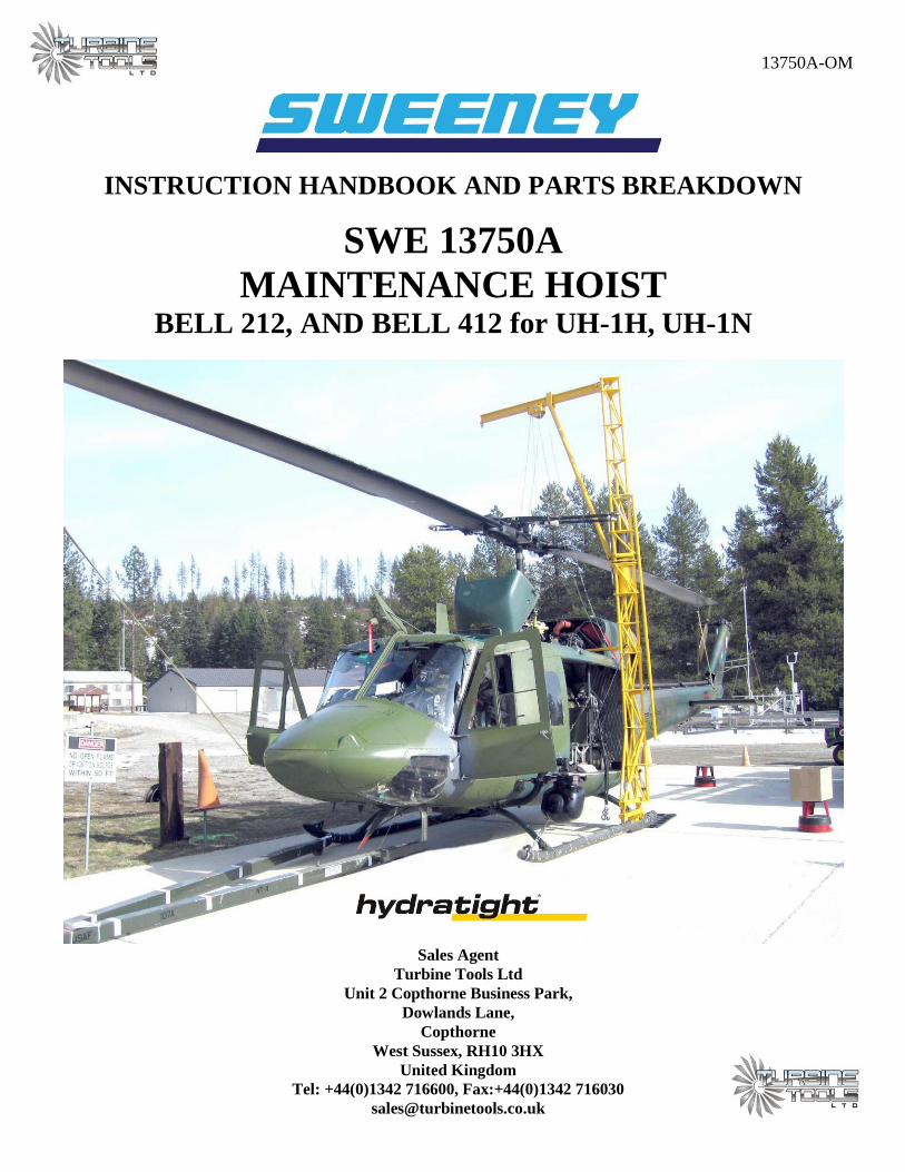
INSTRUCTION HANDBOOK AND PARTS BREAKDOWN
SWE 13750A
MAINTENANCE HOIST BELL 212, AND BELL 412 for UH-1H, UH-1N
Sales Agent
Turbine Tools Ltd
Unit 2 Copthorne Business Park,
Dowlands Lane,
Copthorne
West Sussex, RH10 3HX
United Kingdom
Tel: +44(0)1342 716600, Fax:+44(0)1342 716030

OM-13750A Page 1 of 10
SECTION I
INTRODUCTION, PURPOSE AND DESCRIPTION
1-1. INTRODUCTION
1-2. This manual contains information on the Sweeney Model SWE 13750A Maintenance Hoist, relating to
the following considerations:
a. Transportation and Storage.
b. Assembly and Installation.
c. Operation.
d. Parts Lists.
1-3. PURPOSE
1-4. The Sweeney Model SWE 13750A Maintenance Hoist is used to remove or install the rotor,
transmission or engine on Bell UH-1N series helicopters.
1-5. DESCRIPTION
(Figures 1-1, 1-2, 1-3 & 1-4)
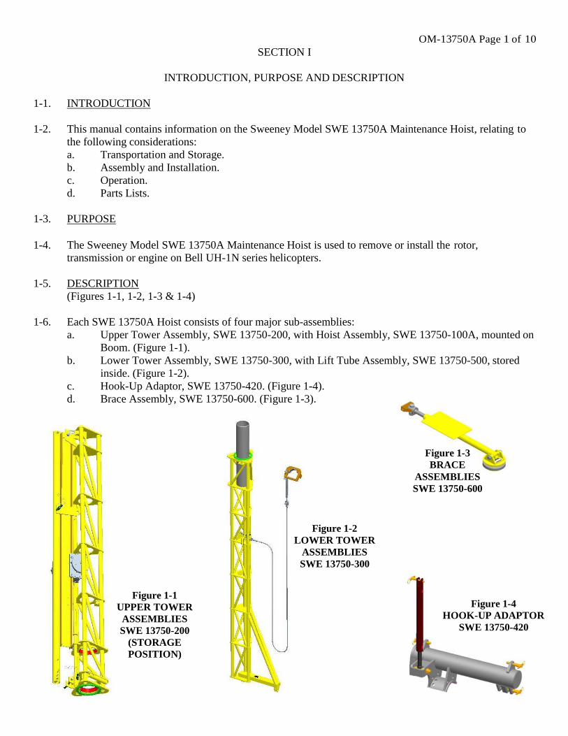
1-6. Each SWE 13750A Hoist consists of four major sub-assemblies:
a. Upper Tower Assembly, SWE 13750-200, with Hoist Assembly, SWE 13750-100A, mounted on
Boom. (Figure 1-1).
b. Lower Tower Assembly, SWE 13750-300, with Lift Tube Assembly, SWE 13750-500, stored
inside. (Figure 1-2).
c. Hook-Up Adaptor, SWE 13750-420. (Figure 1-4).
d. Brace Assembly, SWE 13750-600. (Figure 1-3).
Figure 1-3
BRACE
ASSEMBLIES
SWE 13750-600
Figure 1-2
LOWER TOWER
ASSEMBLIES
SWE 13750-300
Figure 1-1
UPPER TOWER
ASSEMBLIES
SWE 13750-200
(STORAGE
POSITION)
Figure 1-4
HOOK-UP ADAPTOR
SWE 13750-420
OM-13750A Page 2 of 10
SECTION II
TRANSPORTATION AND STORAGE
2-1. INTRODUCTION
2-2. This section contains transportation and storage instructions for the Sweeney Model SWE 13750A
Maintenance Hoist.
2-3. TRANSPORTATION AND STORAGE
(Figures 1-1, 1-2, 1-3, 1-4, and 2-9).
2-4. The SWE 13750A Hoist should be transported and stored as the four major subassemblies described in
paragraph 1-6.
2-5. On the Upper Tower Assembly, SWE 13750-200, note that the Lift Block is screwed to the end of the
Boom to prevent the Hoist Assembly, SWE 13750-100A, from accidentally being run off the end of the
Boom.
a. The Hoist Assembly, SWE 13750-100A, should be in a position on the Boom to allow it to
partially fit between the tubes of the Upper Tower Assembly. (Figure1-1).
b. The Support Tube Assembly, SWE 13750-205, should be attached to the top of the Boom with a
Lock Pin. (Figure 1-1).
c. The Steel Handle, SWE 13750-235, should be attached to the Tube parallel to the long Tubes of
the Upper Tower Assembly, SWE 13750-200. (Figure 1-1).
2-6. The Lift Tube Assembly, SWE 13750-500, should be stored inside the Lower Tower Assembly,
SWE 13750-300, within the holes provided for that purpose. (Figure 1-2).
2-7. The Brace Nut should be threaded on the Roof Anchor of the Brace Assembly, SWE 13750-600.
(Figure 1-3).
2-8. Make sure that all of the Lock Pins are in their respective holes, so that they are no lost.
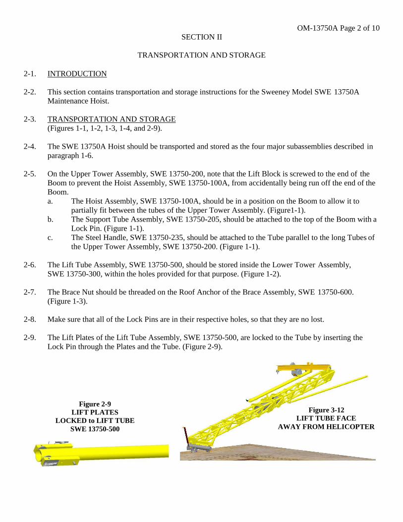
2-9. The Lift Plates of the Lift Tube Assembly, SWE 13750-500, are locked to the Tube by inserting the
Lock Pin through the Plates and the Tube. (Figure 2-9).
Figure 2-9 LIFT PLATES
LOCKED to LIFT TUBE
SWE 13750-500
Figure 3-12 LIFT TUBE FACE
AWAY FROM HELICOPTER
OM-13750A Page 3 of 10
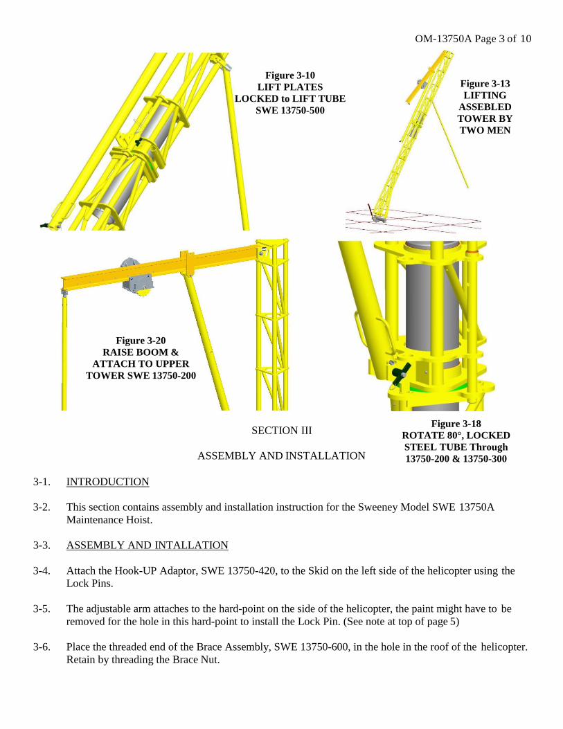
Figure 3-10
LIFT PLATES
LOCKED to LIFT TUBE
SWE 13750-500
Figure 3-13
LIFTING
ASSEBLED
TOWER BY
TWO MEN
Figure 3-20
RAISE BOOM &
ATTACH TO UPPER
TOWER SWE 13750-200
SECTION III
ASSEMBLY AND INSTALLATION
Figure 3-18
ROTATE 80°, LOCKED
STEEL TUBE Through
13750-200 & 13750-300
3-1. INTRODUCTION
3-2. This section contains assembly and installation instruction for the Sweeney Model SWE 13750A
Maintenance Hoist.
3-3. ASSEMBLY AND INTALLATION
3-4. Attach the Hook-UP Adaptor, SWE 13750-420, to the Skid on the left side of the helicopter using the
Lock Pins.
3-5. The adjustable arm attaches to the hard-point on the side of the helicopter, the paint might have to be
removed for the hole in this hard-point to install the Lock Pin. (See note at top of page 5)
3-6. Place the threaded end of the Brace Assembly, SWE 13750-600, in the hole in the roof of the helicopter.
Retain by threading the Brace Nut.
OM-13750A Page 4 of 10
3-7. Lay the Lower Tower Assembly, SWE 13750-300, on the ground at right angles to the helicopter with
the foot facing towards the front of the helicopter. Attach the Lower Tower to the Hook-Up Adaptor,
SWE 13750-420, using the Lock Pins.
3-8. Remove the Lift Tube Assembly, SWE 13750-500, from its storage position, inside of the Lower Tower
Assembly, SWE 13750-300.
3-9. Place the Upper Tower Assembly, SWE 13750-200, over the Pivot Tube of the Lower Tower Assembly,
SWE 13750-300.
3-10. Slip the Steel Handle through the first set of tab holes on the Upper Tower Assembly and the top of the
Lower Tower Assembly. Retain with the Lock Pin. This is to prevent the Upper Tower Assembly from
rotating about the Lower Tower Assembly while the Towers are being erected. (Figure 3-10).
3-11. Remove the Support Tube Assembly from its storage position on top of the Boom. Attach the top end of
the Support Tube Assembly to the bracket on the underside of the Boom with the Lock Pin.
3-12. Attach Lift Tube Assembly, SWE 13750-500, to the lower side of the Upper Tower, SWE 13750-200,
with the Lock Pin. The free end of the Lift Tube should face away from the helicopter. (Figure 3-12).
3-13. Two men can now erect the Maintenance Hoist by starting at the top and walking it up like a ladder.
When the top is several feet off of the ground one man should push on the Lift Tube Assembly, SWE
13750-500, while the other pushes on the Tower, (Figure 3-13).
3-14. After the Maintenance Hoist is vertical attach the Brace Assembly, SWE 13750-600, to the Lower
Tower, SWE 13750-300, using the Lock Pin. Before installing the Lock Pin adjust the threaded portion
of the Brace Assembly so that the Maintenance Hoist will be vertical.
3-15. Clamp the bracket that is on the end of the Cable Assembly to the front of the skid tube. The tang on the
bracket fits inside of the eyebolt on the skid tube. Adjust Turnbuckle until the Cable Assembly is tight.
3-16. Remove the Steel Handle that is holding the Upper Tower Assembly, SWE 13750-200, from rotating
and place it in the horizontal tube on the Upper Tower. Retain the Steel Handle with the Lock Pin.
3-17. Remove the Lift Tube Assembly, SWE 13750-500, from the Upper Tower Assembly.
3-18. Rotate the Upper Tower Assembly approximately 80(line-up to next set of tab holes on the Upper
tower) towards the rear of the helicopter. Remove the Steel Handle and reinsert through set of holes of Upper and Lower Tower for prevent rotating while raising the Boom. (Figure 3-18).
3-19. Thread the Lift Tube Assembly, SWE 13750-500, to the Adaptor on the Boom.
3-20. Using the Lift Tube Assembly raise the Boom until it is horizontal. Secure the Boom in position by
attaching the lower end of the Support Tube Assembly to the Upper Tower Assembly, SWE 13750-200,
with the Lock Pin. (Figure 3-20).
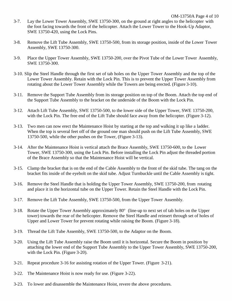
3-21. Repeat procedure 3-16 for assisting rotation of the Upper Tower. (Figure 3-21).
3-22. The Maintenance Hoist is now ready for use. (Figure 3-22).
3-23. To lower and disassemble the Maintenance Hoist, revere the above procedures.
OM-13750A Page 5 of 10
NOTE:
In connection with Paragraph 3-5, to keep the weldment of the Hook-Up Adaptor SWE 13750-420
relatively level when a load is on the tower, lengthen the adjustable arm as much as possible before attaching it
to the hard-point on the helicopter. To do this, step on the inboard portion of the weldment.
When removing more then one component (engine, transmission or rotor), or when the weight of the
helicopter is otherwise noticeably changed while the tower is mounted, readjust the adjustable arm on the Hook-
Up Adaptor. This can be done without lowering the tower, but not while a load is on the tower.
SECTION IV
OPERATION
4-1. INTRODUCTION
4-2. This section covers operation of the SWE 13750A Maintenance Hoist.
4-3. GENERAL
4-4. The SWE 13750A Maintenance Hoist can be used to remove or install the helicopter rotor, transmission,
or engine.
a. The Hoist Assembly, SWE 13750-100A, is a hand-operated Chain Hoist. Chains are provided to
position the Hoist on the Boom and to raise and lower the load. Both are self-locking so that the
load will stay in position. Instructions affixed to the Hoist explain the method of adjusting brake.
b. The Upper Tower Assembly, SWE 13750-200, rotates about the Lower Tower Assembly, SWE
13750-300, on Teflon bearing surfaces. These surfaces should be kept clean when in use.
The Upper Tower Assembly must always be rotated toward the rear of the helicopter. Stops are
provided to prevent it from being rotated forward. The Steel Handle, SWE 13750-235, is used to
assist the rotation.
c. When rotating the Upper Tower Assembly, SWE 13750-200, the load should be positioned as
close to the tower as possible.
d. To prevent the cable from kinking, tension should be kept on it when it is being raised or lowered.
Figure 3-21
REATTACH STEEL
HANDLE in HORIZONTAL
POSITION to SWE 13750-200
Figure 3-22 READY to USE.
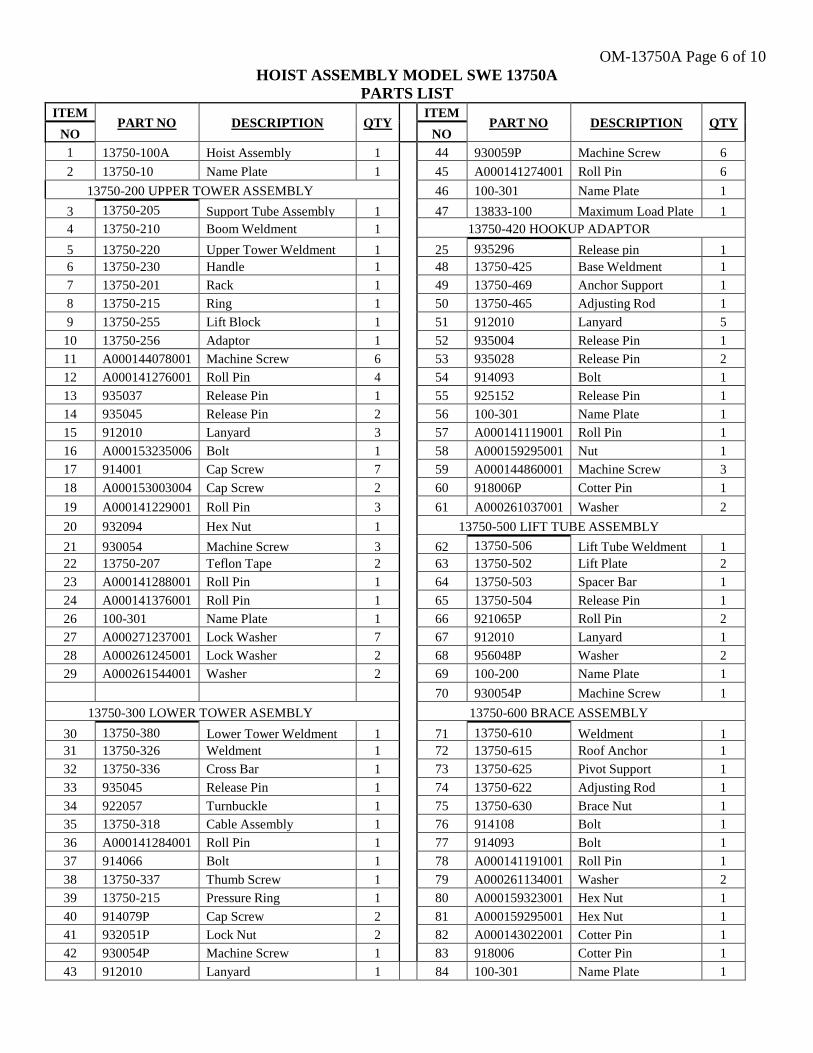
OM-13750A Page 6 of 10
HOIST ASSEMBLY MODEL SWE 13750A
PARTS LIST
ITEM PART NO DESCRIPTION QTY
ITEM PART NO DESCRIPTION QTY
NO NO
1 13750-100A Hoist Assembly 1 44 930059P Machine Screw 6
2 13750-10 Name Plate 1 45 A000141274001 Roll Pin 6
13750-200 UPPER TOWER ASSEMBLY 46 100-301 Name Plate 1
3 13750-205 Support Tube Assembly 1 47 13833-100 Maximum Load Plate 1
4 13750-210 Boom Weldment 1 13750-420 HOOKUP ADAPTOR
5 13750-220 Upper Tower Weldment 1 25 935296 Release pin 1
6 13750-230 Handle 1 48 13750-425 Base Weldment 1
7 13750-201 Rack 1 49 13750-469 Anchor Support 1
8 13750-215 Ring 1 50 13750-465 Adjusting Rod 1
9 13750-255 Lift Block 1 51 912010 Lanyard 5
10 13750-256 Adaptor 1 52 935004 Release Pin 1
11 A000144078001 Machine Screw 6 53 935028 Release Pin 2
12 A000141276001 Roll Pin 4 54 914093 Bolt 1
13 935037 Release Pin 1 55 925152 Release Pin 1
14 935045 Release Pin 2 56 100-301 Name Plate 1
15 912010 Lanyard 3 57 A000141119001 Roll Pin 1
16 A000153235006 Bolt 1 58 A000159295001 Nut 1
17 914001 Cap Screw 7 59 A000144860001 Machine Screw 3
18 A000153003004 Cap Screw 2 60 918006P Cotter Pin 1
19 A000141229001 Roll Pin 3 61 A000261037001 Washer 2
20 932094 Hex Nut 1 13750-500 LIFT TUBE ASSEMBLY
21 930054 Machine Screw 3 62 13750-506 Lift Tube Weldment 1
22 13750-207 Teflon Tape 2 63 13750-502 Lift Plate 2
23 A000141288001 Roll Pin 1 64 13750-503 Spacer Bar 1
24 A000141376001 Roll Pin 1 65 13750-504 Release Pin 1
26 100-301 Name Plate 1 66 921065P Roll Pin 2
27 A000271237001 Lock Washer 7 67 912010 Lanyard 1
28 A000261245001 Lock Washer 2 68 956048P Washer 2
29 A000261544001 Washer 2 69 100-200 Name Plate 1
70 930054P Machine Screw 1
13750-300 LOWER TOWER ASEMBLY 13750-600 BRACE ASSEMBLY
30 13750-380 Lower Tower Weldment 1 71 13750-610 Weldment 1
31 13750-326 Weldment 1 72 13750-615 Roof Anchor 1
32 13750-336 Cross Bar 1 73 13750-625 Pivot Support 1
33 935045 Release Pin 1 74 13750-622 Adjusting Rod 1
34 922057 Turnbuckle 1 75 13750-630 Brace Nut 1
35 13750-318 Cable Assembly 1 76 914108 Bolt 1
36 A000141284001 Roll Pin 1 77 914093 Bolt 1
37 914066 Bolt 1 78 A000141191001 Roll Pin 1
38 13750-337 Thumb Screw 1 79 A000261134001 Washer 2
39 13750-215 Pressure Ring 1 80 A000159323001 Hex Nut 1
40 914079P Cap Screw 2 81 A000159295001 Hex Nut 1
41 932051P Lock Nut 2 82 A000143022001 Cotter Pin 1
42 930054P Machine Screw 1 83 918006 Cotter Pin 1
43 912010 Lanyard 1 84 100-301 Name Plate 1
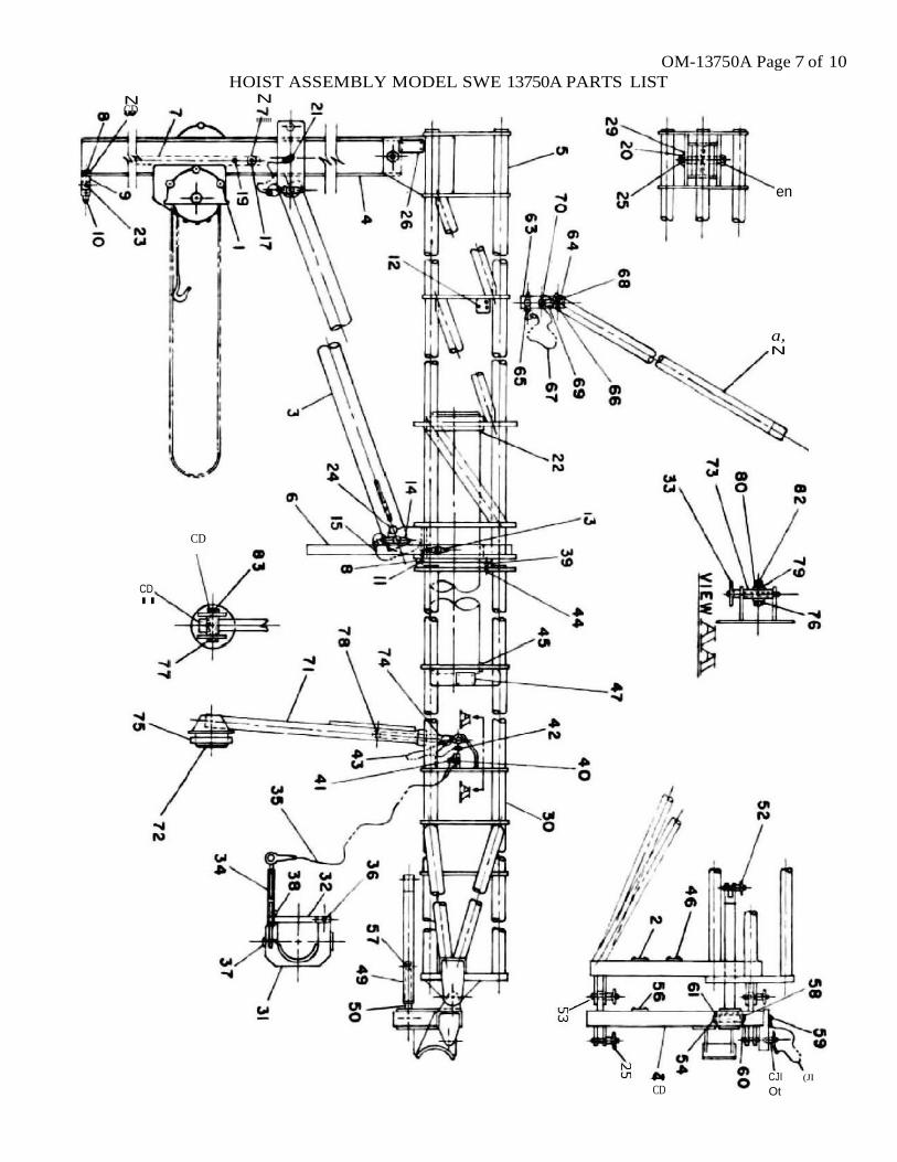
OM-13750A Page 7 of 10
..
HOIST ASSEMBLY MODEL SWE 13750A PARTS LIST N N CD
"""'
en
a, N
CD
.CD.
CJI (JI
CD Ot
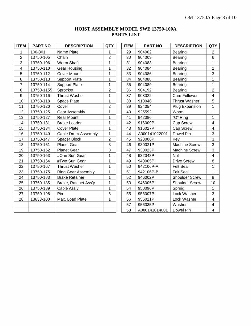
OM-13750A Page 8 of 10
HOIST ASSEMBLY MODEL SWE 13750-100A
PARTS LIST
ITEM PART NO DESCRIPTION QTY
1 100-301 Name Plate 1
2 13750-105 Chain 2
3 13750-106 Worm Shaft 1
4 13750-110 Gear Housing 1
5 13750-112 Cover Mount 1
6 13750-113 Support Plate 1
7 13750-114 Support Plate 1
8 13750-1155 Sprocket 2
9 13750-116 Thrust Washer 1
10 13750-118 Space Plate 1
11 13750-120 Cover 2
12 13750-125 Gear Assembly 1
13 13750-127 Rear Mount 1
14 13750-131 Brake Loader 1
15 13750-134 Cover Plate 1
16 13750-140 Cable Drum Assembly 1
17 13750-147 Spacer Block 2
18 13750-161 Planet Gear 3
19 13750-162 Planet Gear 3
20 13750-163 #One Sun Gear 1
21 13750-164 #Two Sun Gear 1
22 13750-167 Thrust Washer 1
23 13750-175 Ring Gear Assembly 1
24 13750-183 Brake Retainer 1
25 13750-185 Brake, Ratchet Ass'y 1
26 13750-189 Cable Ass'y 1
27 13750-198 Pin 3
28 13633-100 Max. Load Plate 1
ITEM PART NO DESCRIPTION QTY
29 904002 Bearing 2
30 904009 Bearing 6
31 904083 Bearing 1
32 904084 Bearing 2
33 904086 Bearing 3
34 904088 Bearing 1
35 904089 Bearing 1
36 904192 Bearing 2
37 908022 Cam Follower 4
38 910046 Thrust Washer 5
39 924054 Plug Expansion 1
40 925592 Worm 1
41 942086 "O" Ring 1
42 916009P Cap Screw 4
43 916027P Cap Screw 4
44 A000141022001 Dowel Pin 3
45 928006P Key 3
46 930021P Machine Screw 3
47 930023P Machine Screw 3
48 932043P Nut 4
49 940005P Drive Screw 8
50 942106P-A Felt Seal 1
51 942106P-B Felt Seal 1
52 946002P Shoulder Screw 8
53 946005P Shoulder Screw 10
54 950096P Spring 1
55 956007P Lock Washer 3
56 956021P Lock Washer 4
57 956035P Washer 4
58 A000141014001 Dowel Pin 4
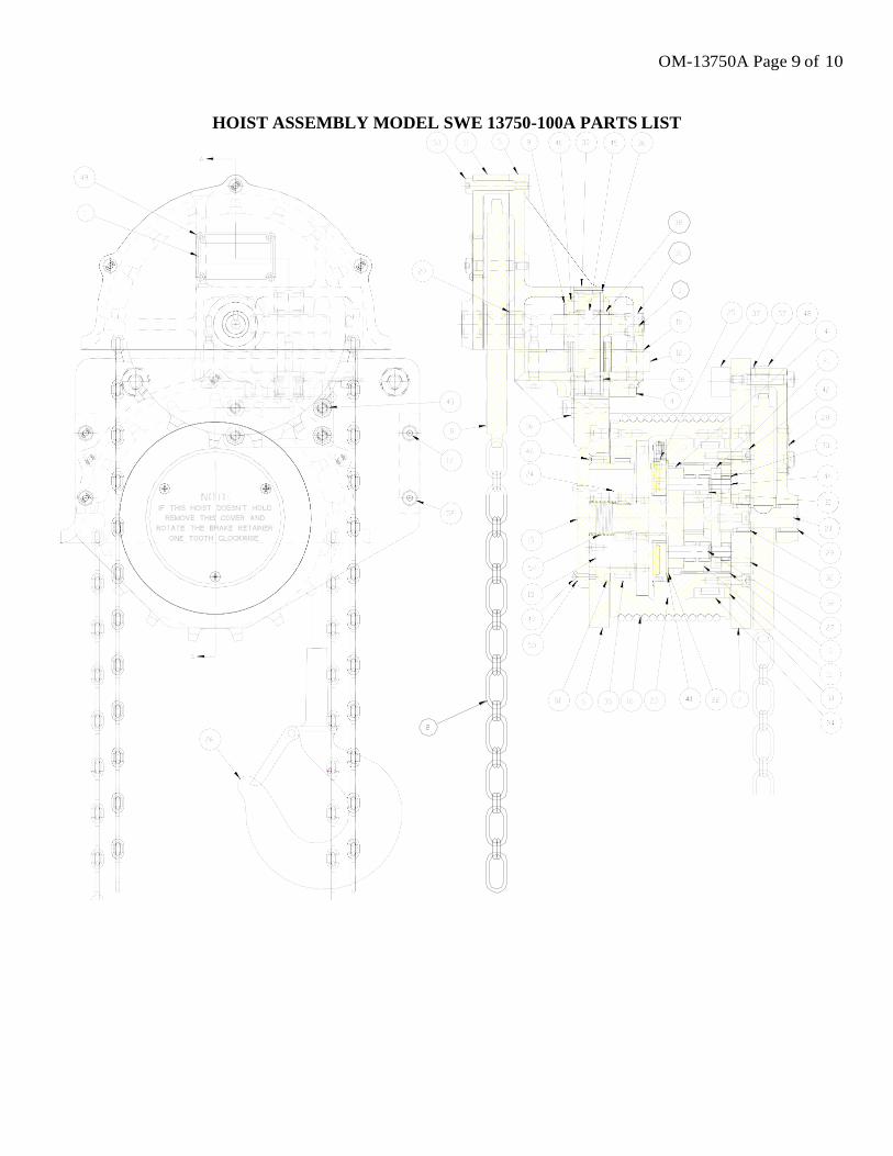
OM-13750A Page 9 of 10
HOIST ASSEMBLY MODEL SWE 13750-100A PARTS LIST
OM-13750A Page 10 of 10


![[XLS] · Web viewHOIST HOIST EQUIPMENT ACTUATOR, MLG HOIST HOIST EQUIPMENT - ACTUATOR, MLG HOIST HOIST - CARDAN PIN HOIST HOIST-CARDAN PIN HOIST HOIST-DEVICE,FLAP TRACK 2-5 HOIST](https://img.pdfslide.us/doc/110x75/5b1fa5177f8b9aa64c8b4800/xls-web-viewhoist-hoist-equipment-actuator-mlg-hoist-hoist-equipment-actuator.jpg)