Embed Size (px)
Citation preview
HME, Incorporated
== HME Ahrens-Fox Spectr Chassis - 2.801 ==
NFPA-1901, 2009 Edition - Complete ApparatusNFPA 1901-2009
The National Fire Protection Association "Standard for Automotive Fire Apparatus, 2009 Edition, is hereby adopted and made a part of these specifications, the same as if it were written out in full detail, with the exception of the section dealing with "Equipment Recommended for Various Types of Apparatus". Bidders shall provide the equipment specifically requested herein and the buyer shall supply the rest before the apparatus is put into service.
Vocation and Basic Attributes - ApparatusAPPARATUS VOCATION AND BASIC ATTRIBUTES
When completed this HME Ahrens-Fox fire apparatus shall have the following attributes: Order Information: Apparatus Builder: HME, Incorporated Sales Representative: User Information: End User: Mailing Address: City: State:
Zip Code: F.D. Contact:
Phone Number: Fax Number: contacts email:
Hose well options: Indicate the hose that shall be installed in the well. Hosewell Location: ___ - Officer's ___ - Center ___ - Driver's Hose Brand: Hose Model: Hose Size: ____________ inch Number of feet required: If more than one hosewell is ordered indicate on a separate piece of paper the information for the other well. Is there an overall height restriction? DO NOT MAKE AN ASSUMPTION ON A HEIGHT ISSUEPLEASE ENTER THE INFORMATION
___ - Inches ground to the top of the highest part of apparatus when fully loaded Are there minimum angle of approach or departure angle requirements? If so fill in the blank.
22586-0001 04/15/141
HME, Incorporated
Minimum angle of approach - __________ degrees Minimum angle of departure - __________ degrees
Paint Codes and Basic Attributes - ApparatusPAINT CODES AND BASIC ATTRIBUTES
Paint Information Paint Manufacturer: Dupont Imron is HME Standard Paint
CAB EXTERIOR Single Color: Primary color:NA Primary paint code:NA
Two Tone Color: Upper paint color:White Upper paint code:8006 Lower paint color:Red Lower paint code:FBCH 71663
Paint Break Line (Scheme #):SFNote: If option for a Custom Two-Tone Paint is selected a drawing, with dimensions, must be attached for order entry. The HME 3A paint scheme will be used if no paint scheme is specified.
BODY PAINT Color Body Panels Color:* Red Color Body Panels Code:* FBCH 71663 If the hosebed sides are painted are they the same color as the body panels?: If not complete the following: Hosebed Wall Color:* Hosebed Wall Code:* RIMS Color Painted Rims Color: * NA Color Painted Rims Code: * NA *Unless noted elsewise the cab lower color will be used when painted rims are selected.
FRAME RAILS Color Painted Frame Color: * NA Color Painted Frame Code:* NA *Unless noted elsewise the cab lower color will be used when painted rails are selected.
Custom Chassis - Vertically Integrated BuilderCUSTOM CHASSIS - SINGLE SOURCE MANUFACTURER
The chassis shall be designed and manufactured by the apparatus builder in the manufacturer's facility. The manufacturer shall demonstrate evidence of manufacturing similar custom vehicles for at least fifty (50) years.
Bids shall only be accepted from a single source apparatus manufacturer. The definition of single source shall be "a manufacturer that designs and manufactures their products using an integrated approach, including the cab and chassis, pump module, and apparatus body being fabricated and assembled on the bidder's premises". The warranties relative to the chassis and body design (excluding component warranties such as engine, transmission, axles, pump, etc.) must be
22586-0001 04/15/142
HME, Incorporated
from a single source manufacturer and not split between manufacturers (i.e. body and chassis). The bidder shall provide evidence that they comply with this requirement. No exceptions will be permitted to this section of the document.
The chassis shall be designed and manufactured for heavy duty fire service with adequate strength and capacity for all components as detailed within these specifications.
Triple Frame RailsCHASSIS FRAME The frame shall be designed to industry standards. The manufacturer shall provide a life time frame side rail warranty to the original purchaser of the chassis. The frame rails shall be 10.5" x 3.5" x .375" heat treated steel. Two (2) inner frame side rail liners with dimensions of 9.687" x 3.125" x .3125" and 9.0" x 4.0" x .3125" shall be added to provide additional strength and reduce deflection. The second rail shall extend from the centerline of front axle and taper 45 degrees forward and shall extend to the rear of the main frame rail. The third rail shall extend from the rear of the front rear spring hanger to the front of the forward rear spring hanger. The frame side rails shall be 110,000 psi minimum yield and shall have a minimum section modulus of 40.09 cu. in. calculated by using the geometric shape method. The resulting frame rail resistance to bending moment shall be 4,406,900 in. lb. per rail (44.90 cu. in., 4,939,088 in. lb. square corner).
To insure the maximum clamp load for the fastener prevailing torque the crossmembers shall be bolted in place using grade 8 bolts, hardened washers, and grade "C" distorted thread locknuts. Flanged head fasteners are not acceptable. The top of the frame rails shall be free of bolt heads. Frame engine cutouts shall be made with a plasma torch to minimize the heat affected zone of the cut. All cutouts shall have a minimum of 6 inch transition between rail flange cut depths to reduce the stress concentrations throughout the cutout area. The root of all transition areas shall have a minimum of a 2 inch radius to reduce stress concentrations at the root.
The main and first inner frame side rails shall be powder coated prior to chassis painting to reduce the effect of harsh road chemicals.
Cab Main Frame CrossmemberCAB MAIN FRAME CROSSMEMBER
In addition to the rear cab support crossmember there shall be a main frame cross member mounted in the rear cab area. This cross member shall be a wide base flanged design to provide frame spacing and excellent strength to prevent frame paralleling. Every frame cross member shall be bolted in place using grade 8 bolts, hardened washers, and grade "C" distorted thread locknuts.
Frame WarrantyFRAME WARRANTY
The frame and cross members shall carry a limited lifetime warranty to the original purchaser. The warranty shall include conditional items listed in the detailed warranty document which shall be provided upon request.
Front Axle 22,500# - Meritor MFSFRONT AXLE
The front axle shall be a MERITOR model "MFS20-133A-N" with a 22,500 lb. capacity.
22586-0001 04/15/143
HME, Incorporated
45° Cramp AngleCRAMP ANGLE
The chassis shall have a turning cramp angle of 45-degrees. Both left and right turns have a full 45° cramp angle with tires and wheels mounted on the axle and installed in the chassis. The 45°cramp angle is achieved irrespective of options such as front suctions and disc brakes.
Oil Seals - Front Axle - Factory PremiumFRONT AXLE OIL SEALS
The front axle shall be equipped with oil bath type oil seals as supplied on the axle from the axle manufacturer. The spindles shall be equipped with transparent covers for oil level inspection.
S-Cam Brakes - Front AxleFRONT AXLE BRAKES
The front brakes shall be Cam-Master Q Plus, 16-1/2" X 6" (419 x 152), S-Cam, air operated heavy duty brakes for increased stopping power and brake life in severe braking applications.
The "S" cam brakes shall incorporate a double anchor pin design, for stability and smooth consistent stopping. The camshafts shall be heat treated with rolled spline construction.
The front axle shall be equipped with automatic slack adjusters (ASA) to provide optimum brake performance.
Front Suspension 22,500# - Semi-Elliptical SpringFRONT SUSPENSION The front suspension shall be a pin and shackle design. Front springs shall be an elliptical leaf type, 53" x 3-1/2" x .5" forged steel. The front springs shall have a military wrapper for safe operation. All front spring pins shall be ground heat treated steel with grease fittings for lubrication. The entire front suspension shall be designed for heavy duty custom fire apparatus with a capacity at ground of 22,500 lbs.
Shock Absorbers - Front AxleDouble acting hydraulic shock absorbers are to be installed.
Steering - 22,500# - Sheppard Dual GearSTEERING SYSTEM
The steering shall be equipped with dual SHEPPARD integral power steering gears. The engine shall be equipped with a gear driven pump.
A remote steel reservoir shall be provided with the ability to check the fluid level when the cab is in the lowered position.
Goodyear 425/65R22.5-20PR (L) Front - G296 - 24,600#-26,320#FRONT TIRES The front tires shall be 425/65R22.5-20PR (L) GOODYEAR G-296 MSA tread, tubeless radial tires. These tires shall be mounted on 22.5" x 13.00" rims.
22586-0001 04/15/144
HME, Incorporated
22,800# - Std Load Rating G296 425/65R22.5 LSTANDARD LOAD RATING The front axle GAWR using these tires shall be 22,800 lbs. @ 120 psi.
Tire Speed Rating - 65 MPHTIRE SPEED RATING The maximum tire speed rating is 65 MPH.
Front - Aluminum Wheels - 13.00ALUMINUM WHEELS Two (2) polished aluminum wheels shall be supplied and installed on the front axle. The 22.5" x 13.00" wheels shall be highly polished on the outboard side.
Stainless 'Baby Moon' Caps & NutcoversFRONT WHEEL TRIM The front axle shall be trimmed with mirror finish, 304L grade, non-corrosive stainless steel 'baby moon' hub caps with an opening for viewing the oil seal cover, and bright finished nut covers.
Tandem Rear Axle 58,000#-60,000# - Meritor RT-58-185REAR TANDEM AXLE
The rear axle shall be a MERITOR model "RT-58-185" in a tandem axle assembly with a 58,000#/60,000# rating for the fire service.
Tandem - Inter-Axle Differential LockAn inter-axle differential lock shall be provided with an air operated control on the driver's dash. This control shall include a light to indicate the inter-axle differential lock is engaged.
185 Series Differential - Tandem AxleMERITOR DIFFERENTIAL
The rear tandem axle shall contain a Meritor 185 Series differential with a 19-5/8 inch diameter ring gear utilizing hypoid-Generoid gearing and 2-1/4 inch diameter axle shafts.
Axle Lube - Non SyntheticAXLE DIFFERENTIAL LUBE
The axle shall have the initial factory fill made with non-synthetic axle lube meeting the axle manufacturer's recommendations.
Oil Seals - Rear Axle - Factory PremiumREAR AXLE OIL SEALS
The rear axle shall be equipped with premium oil bath type oil seals as supplied on the axle from the axle manufacturer.
S-Cam Brakes - Tandem Rear AxleREAR AXLE BRAKES
22586-0001 04/15/145
HME, Incorporated
The rear brakes shall be Cam type, 16-1/2" X 7" (419 x 178), S-Cam, air operated heavy duty brakes for increased stopping power and brake life in severe braking applications.
The "S" cam brakes shall incorporate a double anchor pin design, for stability and smooth consistent stopping. The camshafts shall be heat treated with rolled spline construction.
The rear axle shall be equipped with automatic slack adjusters (ASA) to provide optimum brake performance.
Vehicle Top Speed 62 - 65 MPHVEHICLE TOP SPEED The rear axle shall be geared for a top speed of 62 to 65 mph at engine governed RPM.
NFPA Vehicle Top Speed StatementNFPA TOP SPEED STATEMENT NFPA-1901, 2009 Edition - 4.15.2 The maximum top speed of fire apparatus with a GVWR over 26,000 lb (11,800 kg) shall not exceed either 68 MPH (105 km/hr) or the manufacturer's maximum fire service speed rating for the tires installed on the apparatus, whichever is lower.
NFPA-1901, 2009 Edition - 4.15.3 If the combined water tank and foam agent tank capacities on the fire apparatus exceed 1250 gal (4732 L), or the GVWR of the vehicle is over 50,000 lb (22,680 kg), the maximum top speed of the apparartus shall not exceed either 60 MPH (105 km/hr) or the manufacturer's maximum fire service speed rating for the tires installed on the apparatus, whichever is lower.
The speed selected on this apparatus exceeds 60 MPH (105 km/hr) and the customer is aware of NFPA-1901 and the top speed that will be achieved with the finished apparatus.
Tandem Suspension 58,000# - Hendrickson RT Walking BeamTANDEM AXLE REAR SUSPENSION The rear suspension shall be HENDRICKSON "RT-650" (spring) Series Suspension, rated to match the capacity of the rear axle. The RT suspension shall have a clamp style #1 spring hanger, with double-lock bolt design to help absorb the forces of braking and acceleration. The double-lock bolt design shall provide longer hanger and spring eye bushing life. The #2 spring hanger cam and leg areas shall be hardened to extend life and durability. The suspension saddles shall be cast steel with robotically welded, fabricated walking beams for superior strength-to-weight ratio. The walking beam shall have the bar pin beam end connection for extended service life and ease of axle alignment and maintenance.
The suspension shall be supplied with longitudinal rubber bushed torque rods to prevent axle rotation during acceleration and braking. The rear suspension crossmember shall be a 1/4" thick 50,000 psi yield full liner through the suspension area with a double channel torque rod crossmember bolted into the liner to form a rear suspension "H-member".
TANDEM AXLE REAR SUSPENSION - RATING The tandem axle suspension shall have a rated capacity of 58,000 lbs. The suspension shall be provided with bronze center bushings and rubber end bushings.
The walking beams for the tandem axle suspension shall be 56 inches in length.
22586-0001 04/15/146
HME, Incorporated
Air System - Color Coded Nylon Air Lines - Tandem AxleAIR SYSTEM An air brake system meeting the requirements of the FMVSS-121 shall be provided. The system shall consist of four (4) reservoirs with a 6,543 cu. in. volume. The air system shall consist of the following components: Dual air system with dual gauges and a warning light and buzzer. A spring actuated parking brake built into the rear axle brakes with a manual control and warning light the in cab. These shall automatically apply in case of air system failure. A mechanical means of releasing the spring brake shall be provided in the event of total loss of air pressure. A quick build up system shall be provided, capable of building enough air pressure to release the spring brake in less than thirty (30) seconds, when starting with the entire air system at zero pounds pressure. The brake system shall be a split system. One (1) system serving the rear brakes and one (1) system serving the front brakes. The two (2) systems shall be connected with a double check valve that shall automatically shuttle air from the front system to the rear system should loss of air pressure occur. This system shall also modulate the amount of air so the spring brakes shall apply in direct relationship to the amount of pressure applied to the treadle valve.
The brake system shall be equipped with a Bendix SR-1 valve to provide modulated spring brakes in the event there is low air pressure in the rear axle air supply reservoir. The spring brakes shall be piped in such a manner that if the treadle valve is depressed while the spring brakes are applied, the spring brakes shall release and remain released as long as the treadle valve is depressed. They shall reapply immediately when the treadle valve is released. The piping in the air system shall be 2-ply nylon reinforced color coded tubing for all stationary lines.
Bendix AD SP DryerAIR DRYER The air system shall include a BENDIX AD-SP air dryer.
The air dryer shall have a spin off desiccant cartridge. The air dryer shall incorporate an integral turbo cutoff valve. The turbo cutoff valve shall close the path between the air compressor and the air dryer purge valve during the compressor "unload" cycle. This shall allow the air dryer to purge the water and contaminates without any loss of turbo boost or engine horsepower. A 12 volt watt heated moisture ejector shall be an integral part of the air dryer. This heater shall be thermo- statically controlled. The electrical connection for the heater shall use a sealed electrical connector to protect against moisture and corrosion.
Air Tank Drains - ManualMANUAL AIR TANK DRAINS All air reservoirs shall have manual 1/4 turn drain valves. The drain valves shall be supplied with rubber seats to reduce air system leaks. The reservoir drain valves shall allow the accumulation of contaminants that are collected in the reservoirs to be drained off to the atmosphere.
Front Axle Service Brake Locking SystemFRONT AXLE SERVICE BRAKE LOCKING SYSTEM
22586-0001 04/15/147
HME, Incorporated
The chassis shall be equipped with a front axle service brake locking system. This system shall be independently operated with a separate selector on the dash. This selector shall be labeled "Front Brake Lock". The control circuit for this system shall only allow application of the front axle service brake engagement when the rear axle parking brakes are applied.
ABS Brake System - 6 Wheel - Meritor/WabcoMERITOR/ROCKWELL/WABCO ABS BRAKE SYSTEM A four channel, single rear axle model, MERITOR/ROCKWELL/WABCO ABS Braking System shall be supplied. A frame mounted electronic control unit (ECU) shall monitor and control wheel speed during braking. Wheel sensors, constantly monitoring wheel speed, send information to the ECU. If a wheel begins to lock the ECU transmits an electrical impulse to modulator valves that can apply, release or hold the air pressure in the brake chambers. The rapid modulation of air pressure prevents wheel lock-up and increases driver control.
This ABS system shall be a 4S/4M system with six (6) wheel speed sensors and six (6) modulator valves. If a fault occurs in one wheel, that wheel shall have normal (non-ABS) brake function. The other wheels shall continue to provide the ABS function. If the ABS system should fail completely, the brake control shall be returned to normal (non-ABS) braking. An ABS warning light shall be installed on the driver's dash message center. This warning light shall cycle through a test stage at the point of ignition turn on and remain illuminated until the vehicle reaches approximately four (4) MPH. The light shall illuminate in other conditions to warn of an ABS system failure and shall illuminate when the diagnostic function is activated.
Stability Enhancement System - 6 Wheel - Meritor/WabcoMERITOR/WABCO STABILITY ENHANCEMENT SYSTEM A Meritor / Wabco Roll Stability Control (RSC) System shall be provided on the apparatus chassis. The RSC shall assist in managing road conditions that may result in a vehicle rollover.
The RSC shall intervene to regulate the vehicle's deceleration functions. by automatically reducing engine torque, engage the vehicle retarder and apply pressure to the brakes.
Electronic Stability Control (ESC) shall be included building upon the established RSC system by sensing the tendency of the vehicle to spin around and automatically applying the brakes to reduce that risk.
This system conforms to the requirements of NFPA-1901 4.13.1.2 - If the apparatus is equipped with a stability control system, the system shall have, at a minimum, a steering wheel position sensor, a vehicle yaw sensor, a lateral accelerometer, and individual wheel brake controls.
Goodyear 315/80R22.5-18PR (J) Rear - G291 - 60,000#REAR TIRES The rear tires shall be 315/80R22.5-18PR (J) GOODYEAR G291 all weather tread, tubeless radial tires. These tires shall be mounted on 22.5" x 9.00" rims. Tandem rear axle GAWR using these tires shall be 58,000 lbs. @ 120 psi.
Tire Speed Rating - 75 MPHTIRE SPEED RATING
22586-0001 04/15/148
HME, Incorporated
The maximum tire speed rating is 75 MPH.
Inner and Outer Rear - TA - Aluminum Wheels - 9.00ALUMINUM WHEELS Eight (8) polished aluminum wheels shall be supplied and installed on the tandem rear axles. The 22.5" x 9.00" wheels shall be highly polished on the outboard side.
Stainless "Lincoln Hat" Hub & Nut CoversREAR WHEEL TRIM The rear axle(s) shall be trimmed with mirror finish, 304L grade non-corrosive stainless steel "Lincoln Hat" hub cover and bright finished nut covers.
Axle & Chassis Laser AlignmentLASER ALIGNMENT The chassis shall have a laser alignment performed at the factory before delivery. Toe In Front Axle - The toe in on a vehicle is set to reduce tire wear and to insure that the vehicle shall steer in a straight line. Toe in measurements are set to a positive 2.5 millimeters total, giving the vehicle 1.25 millimeters from side to side. Toe In Rear Axle - The toe in on the rear wheels is set up slightly different in that the axle and wheels are set to ride the "crown" of the road. This is achieved by adjusting the toe to a measurement of no less than 1 millimeter, but no more that 2 millimeters. The ideal measurement is 1.5 millimeters total for both sides. Cramp Angle - Cramp angle is set to achieve the greatest turning radius possible with the selected components of the vehicle. Each front wheel is set to zero degrees. The wheel is then turned until it reaches the steering stops. This measurement is the cramp angle.
Tire Pressure Monitoring Device - 3 Axles - LED AlertTIRE PRESSURE MONITORING DEVICE Each tire installed on the apparatus shall be equipped with a tire pressure monitoring device. The device shall consist of a valve stem cap to with an LED tire alert to indicate tire pressure conditions. The LED will flash when the tire drops 8 psi below the factory setting.
Cummins ISX12 - 500 HP - EPA13 - 1400 RadiatorDIESEL ENGINE The chassis shall be powered by a Cummins diesel engine as described below:
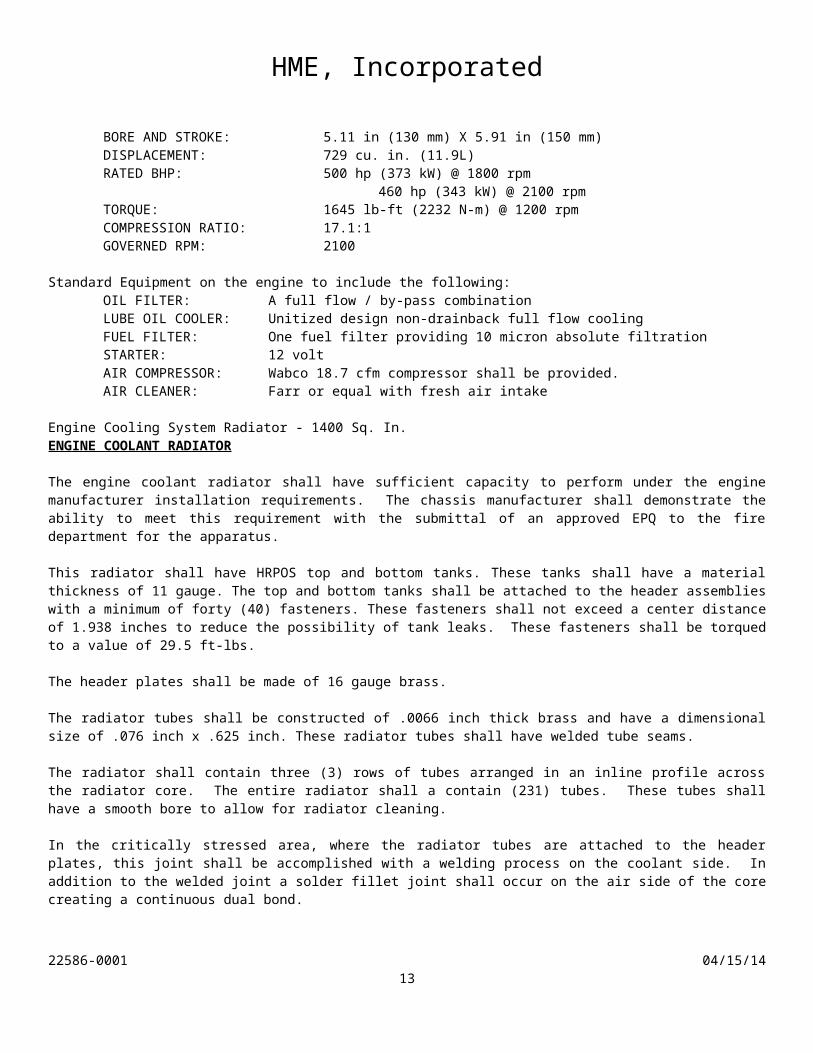
MODEL: ISX12-500 NUMBER OF CYLINDERS: Six BORE AND STROKE: 5.11 in (130 mm) X 5.91 in (150 mm) DISPLACEMENT: 729 cu. in. (11.9L)RATED BHP: 500 hp (373 kW) @ 1800 rpm
460 hp (343 kW) @ 2100 rpmTORQUE: 1645 lb-ft (2232 N-m) @ 1200 rpmCOMPRESSION RATIO: 17.1:1 GOVERNED RPM: 2100
22586-0001 04/15/149
HME, Incorporated
Standard Equipment on the engine to include the following: OIL FILTER: A full flow / by-pass combination
LUBE OIL COOLER: Unitized design non-drainback full flow cooling FUEL FILTER: One fuel filter providing 10 micron absolute filtration
STARTER: 12 volt AIR COMPRESSOR: Wabco 18.7 cfm compressor shall be provided.
AIR CLEANER: Farr or equal with fresh air intake
Engine Cooling System Radiator - 1400 Sq. In.ENGINE COOLANT RADIATOR The engine coolant radiator shall have sufficient capacity to perform under the engine manufacturer installation requirements. The chassis manufacturer shall demonstrate the ability to meet this requirement with the submittal of an approved EPQ to the fire department for the apparatus. This radiator shall have HRPOS top and bottom tanks. These tanks shall have a material thickness of 11 gauge. The top and bottom tanks shall be attached to the header assemblies with a minimum of forty (40) fasteners. These fasteners shall not exceed a center distance of 1.938 inches to reduce the possibility of tank leaks. These fasteners shall be torqued to a value of 29.5 ft-lbs. The header plates shall be made of 16 gauge brass. The radiator tubes shall be constructed of .0066 inch thick brass and have a dimensional size of .076 inch x .625 inch. These radiator tubes shall have welded tube seams. The radiator shall contain three (3) rows of tubes arranged in an inline profile across the radiator core. The entire radiator shall a contain (231) tubes. These tubes shall have a smooth bore to allow for radiator cleaning. In the critically stressed area, where the radiator tubes are attached to the header plates, this joint shall be accomplished with a welding process on the coolant side. In addition to the welded joint a solder fillet joint shall occur on the air side of the core creating a continuous dual bond. The radiator shall have a louvered serpentine type core that contains fins constructed of .0024 inch thick copper. These fins shall be spaced to a maximum density of 14 fins per inch of radiator tube. Each fin shall have a louvered surface for high cooling efficiency. The radiator shall contain an integral coolant de-aeration tank. This tank shall be designed to remove entrapped air or gas from the coolant side of the radiator. The radiator side rails shall have integrally designed support gussets for the transition to the header attachment.
The bottom tank of the radiator shall have a drain valve for coolant removal.
The bottom tank of the radiator shall have a transmission cooler with a plate-type design. The plates shall have internal turbulators to break up laminar oil flow across the surface. The cooler shall have 1311 square inches of surface area for water surface contact and heat transfer. The radiator system shall be pressurized with a cap rated per the cooling system requirements of the specific engine manufacturer. The high efficiency engine fan shall be encompassed with a radiator shroud to provide the proper air flow from the fan blade to the radiator.
22586-0001 04/15/1410
HME, Incorporated
The perimeter of the radiator shall have recirculation baffles to eliminate the possibility of recirculation of "hot" air to the face of the radiator core. The bottom of the radiator shall have a recirculation baffle from the radiator to the frame rails.
Engine Coolant Recovery SystemCOOLANT RECOVERY SYSTEM A coolant recovery system shall be installed on the chassis. This tank is designed to capture coolant overflow when the engine coolant warms and expands. As the engine cools the overflow is then pulled out of the tank and back into the radiator, thus maintaining proper coolant levels.
Charge Air Cooler - Engine Air IntakeCHARGE AIR COOLER RADIATOR The engine charge-air cooler shall have sufficient capacity to perform under the engine manufacturers installation requirements. The chassis manufacturer shall demonstrate the ability to meet this requirement with the submittal of an approved EPQ to the fire department for the apparatus. This radiator shall have cast aluminum side tanks. These tanks shall have a material thickness of .200. These tanks shall be attached to the charge-air core with the ALBRAZE construction technique. The external air fins shall be louvered serpentine and constructed of .006 inch thick aluminum. The internal air fins shall be of the lance-and-offset design for greater air turbulence and higher efficiency. The internal fins are to be constructed of .010 inch thick aluminum. The charge-air cooler shall be mounted directly in front of the engine coolant radiator. To reduce vibration rubber "iso" mounts shall be used for mounting of the charge-air cooler to the engine radiator. The charge air cooler shall contain (12) rows of internal fins within a .313 x 2.632 aluminum tube assembly. This tube assembly shall be constructed of .025 thick aluminum. The charge-air cooler shall contain thermal expansion slots to allow the expansion and contraction of the charge-air core over the wide range of temperatures that are expected in operation. The charge air piping between the engine and charge-air cooler shall be aluminum tubing with a wall thickness of .065 inch. The system shall utilize four (4) ply silicone rubber woven Nomex hoses with stainless steel pressure bands. These bands are designed to maintain the hose shape under the pressure of the turbocharger boost air. All clamps used on the charge air piping are to be stainless steel constant torque and shall be installed at each joint.
Radiator CoolantCOOLANT The coolant system shall contain an ethylene glycol and water mixture to keep the coolant from freezing to a temperature of -34 degrees F.
Premium Cooling System HosesCOOLANT HOSES The entire chassis cooling system shall have premium rubber hoses. All clamps to be stainless steel worm drive type clamps.
22586-0001 04/15/1411
HME, Incorporated
Heater Shut Off ValvesHEATER LINE SHUT OFF VALVES
The heater circuit shall have quarter turn shut off valves installed on both the supply and return lines to allow a complete shut off of coolant flow to the cab heaters in hot seasons of the year. These valves shall be installed in addition to the valves in the heater unit(s).
Engine Oil - First FillENGINE OIL
The engine shall have the initial factory fill made with a non-synthetic engine oil meeting the engine manufacturer's recommendations.
Engine Brake - Cummins ISM/ISX EngineENGINE BRAKE A "JACOBS" Engine Brake shall be supplied. The driver's dash shall include an engine brake control switch. Activation of the engine brake shall occur at zero throttle position. The transmission ECU shall be programmed to operate in the pre-select downshift mode to maximize the retarding power of the engine brake. The brake lights shall illuminate when the Jacobs Brake is in operation. The Jacobs brake shall be inoperative when the chassis is in pump mode. The "JACOBS" engine brake shall be covered under the standard five year Cummins engine warranty.
Fast (High) Idle - Manual Select - Auto Low VoltageENGINE FAST (HIGH) IDLE The chassis shall be equipped with an Electronic Idle Control (EIC) for the electronic engine. Preset speed is factory adjustable. The fast idle provision shall only function when the parking brake is set and the transmission is in neutral. Manual selection of the fast idle shall be controlled by a driver's momentary switch.
Automatic activation of the fast idle shall occur when a low voltage condition exists, the truck is in neutral and the parking brakes are applied.
Cancellation of the fast idle shall be achieved by resetting the manual switch or by depressing the service brake pedal.
Corrosion InhibitorCORROSION INHIBITOR Corrosion inhibitor shall be provided as an additive to the chassis cooling system.
Auxiliary Engine Cooler - SendureAUXILIARY ENGINE COOLER
22586-0001 04/15/1412
HME, Incorporated
The cooling system shall have one (1) SENDURE auxiliary engine cooler mounted in the upper radiator water pipe. The apparatus shall have the fire pump water circulated to the cooler from a valve located on the apparatus pump panel.
Spark Arrestor - Air IntakeSPARK ARRESTOR A spark arrestor shall be installed in the chassis air intake system. This arrestor shall be mounted behind the intake grille to filter out airborne embers.
Fan ClutchHORTON FAN
A fan clutch shall be installed on the engine. A manual switch shall be provided in the dash, to over ride the fan control in event of fan failure or conditions that may result in overheating of the engine.
EPA 2010/2013 Compliant Exhaust Treatment System - ISXEXHAUST SYSTEM A single exhaust pipe shall be provided for the engine. The exhaust pipe shall be supplied with a heat wrap. The wrap shall extend from the engine turbo charger to just below the frame rail.
The exhaust tubing from the turbocharger to the exhaust after treatment device shall be stainless steel.
Cummins Aftertreatment System - EPA10 - ISXCUMMINS AFTERTREATMENT SYSTEM The chassis shall be equipped with a Cummins exhaust after treatment system in compliance with EPA 2010.
Stainless Tailpipe - Curb Side - 90° Exit - Straight Cut EndTAILPIPE The tailpipe shall extend from the exhaust muffler/aftertreatment device to the rear of the vehicle making a 90° bend to exit the vehicle ahead of the rear tires on the curbside of the vehicle. The end of the pipe shall be cut square or perpendicular to the exhaust pipe centerline.
The pipe shall be unpolished stainless steel.
Exhaust Tailpipe DiffuserAn exhaust gas diffuser shall be furnished on the end of the tailpipe.
DEF System - 5 Gallon Reservoir - EPA10DIESEL EXHAUST FLUID SYSTEM The chassis shall be equipped with a 5 gallon Shaw Development Diesel Exhaust Fluid (DEF) reservoir system. The reservoir shall contain an Multifunctional Head Unit (MFHU) that contains integrated level and temperature sensors. The MFHU also shall contain a coolant powered heater to thaw DEF in conditions below 12°F (-11°C) to meet governmental regulations. The reservoir shall be located on the left frame rail behind the front axle beneath the cab. The mounting system shall use stainless steel mounting brackets to reduce the possibility of corrosion.
Allison 4000EVS Automatic TransmissionTRANSMISSION
22586-0001 04/15/1413
HME, Incorporated
The transmission shall be an Allison 4000EVS automatic transmission with electronic controls. The transmission shall be equipped with a lock-up control circuit that shall automatically shift the transmission into 4th gear lock-up when the pump is shifted into gear. TRANSMISSION COOLER An automatic transmission cooler shall be provided as an integral part located in the bottom tank of the radiator. It shall be designed to withstand 165 psi working pressure and an intermittent pressure of 250 psi. The cooler shall be of sufficient size to maintain the operating temperature within the recommended limits of the transmission manufacturer.
Transmission Fluid - Allison TES-389TRANSMISSION FLUID The transmission shall be provided with heavy-duty transmission fluid meeting Allison specification TES-389.
Five Speed Allison Programming - 4000EVSFIVE SPEED PROGRAMMING The transmission shall be programmed for five speeds. The transmission shall have the following gear ratios. First - 3.51Second - 1.91 Third - 1.43 Fourth - 1.00 Fifth - 0.74Reverse - 4.80 The transmission shall be able to shift from first through fifth gear without operator intervention. The chassis shall be geared for the top speed in 5th gear.
Automatic Neutral Programming - 3000EVS / 4000EVSAUTOMATIC NEUTRAL The transmission shall be provided with circuitry to provide automatic neutral. Setting the parking brake commands the transmission to neutral when the park brake is applied, regardless of drive range requested on the shift selector. Requires re-selecting drive range to shift out of neutral.
After the tranmsission has been activated with the automatic neutral feature the shift lever must be returned to neutral and back to drive for midship pump operations.
1810 Series DrivelinesDRIVELINES Universal joints and driveshafts shall be SPICER 1810 series or equal. The driveshaft tube shall be a minimum of 4.5" diameter with a .259" tube wall thickness. The driveshaft slip joints shall be coated to reduce sliding friction and thrust under high torque loads. Permanent driveline installations shall be balanced to prevent vibration.
Fuel Tank - 50 Gallon - 75' Aerial InstallationFUEL TANK
22586-0001 04/15/1414
HME, Incorporated
The fuel tank shall have a minimum capacity of 50 gallons (US) and be D.O.T. certified. It shall be mounted between the frame rails. The tank construction shall be of 12 gauge steel. The baffled tank shall be vented to prevent low vacuum and facilitate rapid filling. A drain plug shall be provided in the bottom of the tank. The tank shall have a 2" NPT fill to the rear of the chassis. The fuel tank sending unit is to be mounted to the rear of the fuel tank for easy replacement without removing body panels.
Reinforced Fuel LinesFUEL LINES Polyamide fiber, nylon braided, reinforced tubing with push-on reusable fittings shall be provided for the chassis fuel lines.
Fuel Filter - Cummins - FactoryFUEL/WATER SEPARATOR The Cummins engine shall be equipped with an integrated fuel / water separator with a self venting bottom drain valve. This filter shall be able to remove up to 95% of dissolved water and up to 99% of free standing water.
270 Amp Alternator - Leece-Neville - LN4867JALTERNATOR A LEECE-NEVILLE model LN4867J 270 Amp alternator shall be installed on the engine. This alternator is internally rectified and regulated.
3/16" Aluminum - MFDxl - Spectr Tilt Cab - Flat RoofFIRETRUCK CAB The apparatus shall be designed to operate in emergency conditions. These conditions require the apparatus to maneuver into areas at a high rate of speed. To facilitate in these operations a cab-over-engine design is required in order to reduce the overall length of the apparatus thus increasing the maneuverability.
The cab design must be such to provide safe and efficient transport of emergency personnel. The cabin shall be designed with four (4) side doors of the largest size possible and with a grab handle and step arrangement to provide ease of entry and egress.
There shall be up to six (6) positions available for occupant transport with a minimum of four (4) forward facing seating positions in the cab. The number of seats and seating locations are described in detail later in this document.
The apparatus cab shall be of the latest in automotive design, styling and appearance.
CAB MATERIALS AND CONSTRUCTION The extruded aluminum xl cab shall have the following material gauges as a minimum:
· Cab floor - 3/16" (.190") aluminum · Front skin - 3/16" (.190") aluminum · Cab side panels - 3/16" (.190") aluminum · Cab rear wall - 3/16" (.190") aluminum · Cab driver's floor - 3/16" (.190") aluminum· Cab officer's floor - 3/16" (.190") aluminum· Cab crew area floor - 3/16" (.190") aluminum
22586-0001 04/15/1415
HME, Incorporated
· Cab roof - 3/16" (.190") aluminum· Cab doors - 3/16" (.190") aluminum
Roof Rail Section Extending from the front to the rear of the cab above the doors the cab shall have and extruded aluminum section. This section shall be designed to interlock with the roof sheet and incorporate the door drip molding in one single piece.
Upper Transverse Member Amid ship in the cab there shall be a boxed beam header assembly located transverse in the cab from left to right.
Front Door B-Post This vertical box section of the cab located behind each of the front doors provides the slam post for the door latch assembly. This section also is a main member in the cab skeletal system. The B-Post ties into the Upper Transverse Member to provide torsional stiffness in the open space design of the cab.
Rear Door B-Post The box assembly design of the rear door B-post provides an anchor for the rear door latch assembly. This section is the main vertical support at the cab rear corner providing the anchor point for the rear wall structural lattice network.
Roof Panel Rails - The roof panel sub-assembly shall have extruded hat section supports bonded to the roof skin. These roof hat sections shall be joined to the Cab Roof Rail Section to complete the upper cab skeletal structure. These completed Roof Panel Rails shall provide a grid for maximum roof crush and deflection strength. The roof shall support a minimum weight of 250 lbs. / sq. ft. without permanent roof deformation. Rear Wall Rails - The rear wall assembly shall have extruded hat section supports bonded to the wall skin. These sections shall be joined to the Roof Panel Rails and to the rear door slam post and floor provide a rear wall grid structure with maximum strength. Cab Front Wall - The front wall of the cab shall be designed with a double wall construction to reduce the effects of exterior noise in the crew and operator compartment.
CAB DIMENSIONS The cab shall have the following overall dimensional requirements:
· Overall Width - 100 inches · Roof - Flat· Center of front axle to back of cab - 60 inches · Center of front axle to front of cab - 74 inches · Windshield area - 3,756 sq. in. minimum · Front grille opening - 478 sq. in. minimum · Combined side grille opening - 84 sq. in. each minimum· Cab full tilt angle - 45 degrees minimum · Cab full tilt height - 172 inches maximum
Cab interior dimensions shall be provided as a minimum in the following chart:
· Drivers side floor width 25-1/2 inches minimum· Floor to the ceiling in the driver and officers area of the cab 59-1/2 inches minimum· Floor to the top of the doghouse 28-1/2 inches maximum· Officers side floor width 24-1/2 inches minimum· The measurement across the floor from the rear wall to the first vertical portion of the engine
enclosure 39 inches
22586-0001 04/15/1416
HME, Incorporated
· Floor to the ceiling in the rear of the cab 54-1/4 inches minimum CAB DOORS
The cab entry and egress shall be designed for a firefighter in full turnout gear. Each door shall open a minimum of ninety degrees to afford the firefighter maximum space.
The doors shall be of a flush design each having exposed, one-piece, polished stainless steel hinges. The hinge shall be made of 12-gauge material with a minimum hinge pin diameter of 1/4 inch.
The door windows shall have interior and exterior glass weather seals to prevent the influx of exterior air.
The doors shall have exterior and interior paddle type latches for ease of opening with a gloved hand. The paddle latches are to have a rubber gasket, on the outside, separating the handle from the finished painted surface.
FRONT DOORS
The cab front doors shall be of the full-length design enclosing the entire step area of the cab. The door shall be a minimum of 38-1/2 inches wide and 74 inches tall. The front door windows shall have a minimum of 712 square inch area of viewing glass per door. There shall be a fixed piece of forward glass in each of the front doors.
REAR CAB DOORS The rear cab doors shall be similar to the forward doors and shall be located directly behind the front wheel well area. These doors shall be 74 inches high x 34 inches wide. Each door shall have a roll down rear window with a minimum glass viewing area of 670 square inches.
INTERIOR DOOR LOCKS All doors shall have door locks with interior controls and exterior keyed door locks. The installation shall be in conformance with FMVSS 206, with specific adherence to 49 CFR 571.206 Section 4.1.3 requiring that "Each door shall be equipped with a locking mechanism with an operating means in the interior of the vehicle". All doors shall be keyed alike. The doors shall be equipped with appropriate safety interlocks to prevent accidental locking of the doors when closed. DASH TRIM The drivers cab dash console shall be made of black ABS with an appearance of the latest in automotive design, styling. Accompanying the dash console in the forward section of the cab shall be an officers side flat dash for the mounting of a mobile data terminal. The forward overhead console area shall have an automotive styled black ABS covering. This console shall be provided with a center overhead area to house sirens, officer's side speedometer, AM/FM radio and an information center. The console shall have depressed areas for styling with the installation of items such as the visors, electrical access
CAB GLASS AS-1 safety laminate glass shall be used in a two piece, wrap around design with a minimum 3760 square inches of windshield area for maximum visibility. The windshield shall have the style of a one-piece assembly with the practical installation of two pieces for lower replacement cost. The windshield shall be readily available from a nationally recognized automotive glass manufacturer that maintains local distribution outlets.
22586-0001 04/15/1417
HME, Incorporated
All glass shall be tinted. All fixed glass shall be installed with a one-piece triple locked rubber lacing material. Due to long term appearance two-piece chrome trim lock lacing is not desired. SUNVISORS The driver and officer side of the cab shall be equipped with a sun visor. The vinyl covered visors shall be a minimum of 17-1/2" by 9".
DRIVER SIDE ELECTRICAL CABINET
Beneath the drivers seat there shall be an electrical cabinet designed to house the main battery electrical disconnect and facilitate the installation of an onboard battery charger or battery conditioner. A bolt on limited access; aluminum diamond plate hatch shall be installed on the front side of the seat box. The access hatch shall have a louvered section to provide air circulation to the cabinet. This cabinet shall not be used for casual storage. WINDSHIELD WIPERS Two speed electric pantograph wipers shall be installed. These wipers shall have minimum 24" blades and have 28 1/2" wet arm electric pump washers. A 70 oz. Minimum windshield washer reservoir shall be furnished.
STEERING WHEEL AND COLUMN The steering column shall be a DOUGLAS tilt / telescopic type with an integral high beam / turn signal control switch. The column shall have self-canceling design for the turn signal switch. A 4-way warning "Hazard" light switch shall be mounted on the column. For safety, a rubber boot shall be installed to cover the steering shaft from the dash to the floor. The steering wheel shall be a minimum of 18-inch diameter, covered with a padded absorbite finish. A lever on the left side of the steering column shall control the telescopic feature of the steering column. FASTENERS All cab exterior fasteners shall be stainless steel type fastened to the cab with nutserts. BATTERY ACCESS The rear cab steps shall have a removable kick panel, providing access to the batteries for routine maintenance and inspection. CAB CORROSION TREATMENT The cab shall have a corrosion preventative material conforming to Mil Spec C-16173-C, Grade 1, applied during and after construction. A 10-year warranty against perforation due to rust or corrosion shall be furnished for the cab.
Transmission Selector - Lever TypeTRANSMISSION RANGE SELECTOR The transmission shall be controlled by an electro-mechanical lever type shift control. It shall be internally illuminated for night operation and have an internal lock (hold override button) to securely hold the shifter in the position selected.
Transmission Fluid Check - Transmission Selector
22586-0001 04/15/1418
HME, Incorporated
TRANSMISSION OIL LEVEL SENSOR
The transmission shall be equipped with the oil level sensor (OLS). This sensor shall allow the operator to obtain an indication of the fluid level from the shift selector. The sensor display shall provide the following checks, correct fluid level, low fluid level and high fluid level.
Cab Roof - Diamondplate Overlay - Aerial ApplicationROOF EXTERIOR DIAMOND PLATE OVERLAY The cab shall have two 22 inch wide walking surfaces located on the roof with a 46 inch uncovered space in the center. The walking surfaces shall extend from approximately 12 inches of the front of the cab to within 6 inches of the rear of the cab. The material is to be NFPA slip resistant aluminum tread plate.
EMI/RFI Noise SupressionEMI/RFI PROTECTION The apparatus shall incorporate the latest designs in the electrical system with state of the art components to insure that radiated and conducted electromagnetic interference (EMI) and radio frequency interference (RFI) emissions are suppressed at the source. The apparatus proposed shall have the ability to operate in the environment typically found in fire ground operations with no adverse effects from EMI/RFI. EMI/RFI susceptibility is controlled by utilizing components that are fully protected and wiring that utilizes shielding and loop back grounds where required. The apparatus shall be bonded through wire braided ground straps. Relays and solenoids that are suspect to generating spurious electromagnetic radiation are diode protected to prevent transient voltage spikes. In order to fully prevent the radio frequency interference the purchaser shall be requested to provide a listing of the type, power output, and frequencies of all radio and bio medical equipment that is proposed to be used on the apparatus.
Stainless Steel Battery TrayBATTERY BOX TRAY - STAINLESS STEEL The battery box trays shall be stainless steel to reduce the corrosive potential of the tray. The battery hold down and brackets and hardware shall also be made of stainless steel.
Stainless Steel Cover for Battery TrayBATTERY BOX COVER - STAINLESS STEEL To reduce road spray a stainless steel cover shall be installed on each battery box.
Single Battery System - 4 Group 31BATTERY BANK A single battery system shall be provided, utilizing four (4) high cycle type Group 31 batteries. This system shall be capable of engine start after sustaining a continuous 150 amp load for 10 minutes with the engine off (NFPA-1901). A battery disconnect switch (Rated at not less than 450 amps continuous) shall be used to activate the system and provide power to the power panel. A green pilot light shall illuminate to indicate that the1 battery bank is activated.
22586-0001 04/15/1419
HME, Incorporated
BATTERY CABLES All battery wiring shall be "GXL" battery cable capable of handling 125% of the actual load. It shall be run through a heat resistant flexible nylon "HTZL" loom rated at a minimum of 300 degrees Fahrenheit. All cable connections shall be machine crimped and soldered. STARTING CIRCUIT One (1) engine start button is to be located on the lower right dash panel. It shall be wired to heavy duty solenoid rated at not less than 1100 amps. The battery indicator light is to be located directly above the start button to indicate that the battery bank is on.
Battery On Indicator Light - External ViewBATTERY ON INDICATOR LIGHT A steady burning blue Whelen OS Series LED shall be mounted on the driver's dash facing forward to be seen from outside the front of the cab. The light is to illuminate whenever the battery switch is in the on position and the parking brake is set.
40 Amp - Battery Charger - ProMariner 1240BATTERY CHARGER A PRO MARINER / ON BOARD SOLUTIONS, 1240, advanced electronic 4-step battery charger/power supply with a 40 amp output shall be installed, under the driver's seat.
Since shoreline power is not always stable the charger shall be equipped with Auto-Ranging AC Input to automatically accept global voltages of 90 VAC to 270 VAC at 45-440 Hz.
Field Selectable - Use with lead/acid or gel batteries (AGM factory option). Select length of absorption charge cycle based on size of batteries.
In the 4-step charging system the charger will provide the following sequence.
Step 1: Fast Charge - Charger will deliver its maximum amperage rating to the connected batteries for the fastest charge (current regulation mode) until battery voltage is raised to 14.6V (lead acid factory setting). At this time, the ProTech will shift to step 2.
Step 2: Absorption Charge - Maximizes charge and holds voltage (voltage regulation mode) at 14.6V (lead acid factory setting) for 1 to 4 hours (selectable based on battery size), while letting the batteries determine the amount of amps they can accept. This mode creates activity in the batteries, reducing sulfate buildup, and conditions the batteries for an extended life. After the programmed 1 to 4 hours have elapsed, the ProTech will shift to step 3.
Step 3: Float Mode - A precision 13.3V (lead acid factory setting) finishing voltage that maintains each battery (step-down voltage regulation mode), which is perfect for short or long storage periods and will never overcharge your batteries. ProTech will deliver its full rated output for house loads including: lighting, electronics and pumps.
Step 4: Recycle - If there are very large loads on the battery while the charger is on, the unit will recycle to the first step, ensuring that batteries stay fully charged.
One-Year Warranty - Includes lifetime repair guarantee. Certified to - UL Marine 1236/SA
Kussmaul 20 AMP - 120v - Super Auto Eject
22586-0001 04/15/1420
HME, Incorporated
SHORELINE AUTO-EJECT A KUSSMAUL Super Auto Eject, model 091-55-20-120, with weatherproof cover shall be provided. The Super Auto Eject is to be completely sealed to prevent internal contamination of the working components. The internal switch arrangement of the Super Auto Eject shall be designed to close and open the 120-volt AC circuit after the mating connector is inserted and before the connector is removed. This design shall prevent arcing at the connector contacts to provide long life. The electrical connection shall be provided as a 120-volt AC - 20 amp type using a NEMA 5-20P connector.
Yellow Auto-Eject CoverThe Auto-Eject cover shall be a Kussmaul 091-55YW, yellow in color.
Cab Exterior Mounted - Behind the Driver's DoorThe Auto Eject assembly shall be mounted on the exterior of the cab behind the driver's door.
Battery Jumper StudsBATTERY JUMPER STUDS Battery jumper studs shall be provided on the chassis. The jumper studs shall be mounted underneath the cab, on the rear of the driver's side battery box. The studs shall be connected to the chassis batteries with 1/0 color coded cables, red for the positive cable and black for the negative cable. The studs shall be protected with color coded plastic covers when not being used.
Engine Enclosure - Vinyl CoveringENGINE DOGHOUSE The engine doghouse inside the cab will be padded with a layer of sound and heat absorbing foam and covered with heavy duty vinyl trim upholstery to match or accent the interior of the cab.
The under side of the engine enclosure shall be covered with a sandwiched material for interior cab noise and heat rejection. This sandwiched acoustical material shall have one layer of 1/8" foam, a 3/16" single barrier septum and a 7/8" layer of foam to provide on overall thickness of 1-3/16". The sandwich material shall be chemically bonded to prevent layer separation. A finished surface treatment of metalized film shall be provided on the engine side of the barrier. The acoustical barrier shall be held in place with mechanical fasteners in addition to adhesive.
The insulation for protection from heat and sound shall keep the dBa level within the limits stated in the current edition of NFPA 1901.
ACCESS FOR FLUID SERVICING
The engine enclosure shall have a hinged and latched panel to provide access to the engine lubricating oil dipstick, power steering fluid reservoir dipstick and engine coolant recovery reservoir. This access shall allow that these fluid levels can be checked and topped off, if required, without raising the cab.
Brushed Stainless Interior Door PanelsCAB DOORS - INTERIOR TRIM To provided durability and a reflective surface for night operations the interior of the cab doors shall be finished with full length brushed stainless steel panels
22586-0001 04/15/1421
HME, Incorporated
Interior Padding - Standard CeilingINTERIOR CEILING PADDING AND TRIM The cab front interior ceiling shall have a one-piece, removable, vinyl headliner to cover all wiring and tubing used for lights and antenna leads.
Interior Padding - Hushcloth Rugged Rear WallREAR WALL COVERING The rear interior wall of the cab shall have a two-piece, removable, wall covering to finish the interior trim and cover all wiring and tubing used for lights and antenna leads.
The rear wall shall be covered in heavy-duty Hushcloth sound barrier material. The Hushcloth is a three ply material with a 3/16" thick open cell isolation barrier of Polyurethane, a 3/32" thick closed cell Nitrile mid barrier for section reinforcement, and a 1/16" thick embedded pebbled grain wear surface to stand up to the abuse of the fire service in high use departments.
Floor Material - Accoustical Wear MatFLOOR COVERING The front and rear floor areas of the cab shall be covered with "HUSHCLOTH" sound barrier floormats. This floormat shall be a three ply material with a 3/16" thick open cell isolation barrier of Polyurethane, a 3/32" thick closed cell Nitrile mid barrier for section reinforcement, and a 1/16" thick embedded pebbled grain wear surface.
- Rear Wall Gear RackREAR WALL GEAR RACK The rear interior wall of the cab shall have a gear rack to provide eight (8) retracting hooks with a stainless steel scuff plate for hanging personal protective gear.
Cab Door Reflective Material - ChevronCHEVRON - INTERIOR CAB DOOR A red and white chevron reflective striping design shall be installed on each cab door for a total of four (4). The chevron shall be centered on the door kick plate and shall be visible when the cab door is open to traffic.
Cab Door Interior Warning Lights - Red LEDLED WARNING LIGHTS - INTERIOR CAB DOOR Each cab door shall have a PowerArc, model PP4, four (4) inch diameter red flashing LED warning light recess mounted in the lower section of the door. These warning lights shall be wired so all lights illuminate when any cab door is opened.
Cab Step Well Trim - Step Tops and Toe Kick AreaINTERIOR CAB STEP TRIM The cab steps shall be completely enclosed behind each door. The toe kick surface shall be covered with aluminum treadplate trim.
Grab Hndls - Inside - Officer's A-Post and Both Crew Doors
22586-0001 04/15/1422
HME, Incorporated
GRAB HANDLES One (1) additional molded grab handle shall be installed inside the cab. The handle shall be located on the officer's side on the A Post. Two (2) additional molded grab handles shall be installed in the cab. These handles shall be located one each side on the B Posts side of the crew area doors.
Officer's Radio Compartment With DoorRADIO COMPARTMENT WITH DOOR Beneath the officer's seat there shall be a radio compartment with interior dimensions of 19-1/2" wide x 17" long x 7" high. This compartment shall have a side mounted diamond plate door mounted on a piano hinge.
Full Width Intermediate Front Step - 100" CabCAB STEP DIMENSIONS The front cab steps shall have the following overall dimensional requirements:
· Driver's lower step size 10-1/4 inches deep minimum · Driver's lower step size 29-1/2 inches front to back
· Officer's lower step size 10-1/4 inches deep minimum · Officer's lower step size 29-1/2 inches front to back
INTERMEDIATE CAB STEP
The cab shall have a full width intermediate "LaserGrip" anti slip inside step. The intermediate step shall be approximately 9 inches from the top of the lower step to the top of the intermediate step.
INTERIOR CAB STEP TRIM The cab steps shall be completely enclosed behind each door. No portion of the cab entrance step shall be exposed when the door is in the closed position. The lower step shall be sealed from the under side of the cab to eliminate road splash from entering the step area while the vehicle is driving. The horizontal step surfaces shall be covered with bright aluminum tread plate meeting the requirements of NFPA-1901.
The vertical toe kick surface area of the cab step wells shall be covered with aluminum tread plate.
Open Compartment Light - Red Flashing - Whelen OS LEDCOMPARTMENT OPEN LIGHT A Red Open Compartment Flashing Light, Whelen OS Series LED shall be mounted on the driver's side face of the overhead panel. A chrome flange is to be supplied with the light. This light is wired with a flasher to the power panel for completion to circuit on the body. The light circuit shall be wired so that the light circuit is deactivated when the parking brakes of the apparatus are applied.
A label shall be applied adjacent to the light 'DOOR OPEN'.
22586-0001 04/15/1423
HME, Incorporated
Interior Lighting Group - Spectr
Three (3) 7" White LED Dome LightsLED WHITE DOME LIGHTS Two (2) Weldon model 8047 LED, 7” diameter white LED interior dome lights shall be provided. Each light shall be surface mounted and draw 0.85 amps at 12 volts. Lamp shall have V-LED technology LED’s. The lamp shall have field serviceable and upgradeable LED’s and lenses, and carry a 5 year warranty from the manufacturer.
One (1) light shall be installed in the front of the cab centered over the engine doghouse. Two (2) lights shall be installed in the rear crew area and both lights and shall be operated by opening any cab door.
Two (2) 7" Red LED Dome LightsLED RED DOME LIGHTS Two (2) Weldon model 8047 LED, 7” diameter red LED interior dome lights shall be provided. Each light shall be surface mounted and draw 0.85 amps at 12 volts. Lamp shall have V-LED technology LED’s. The lamp shall have field serviceable and upgradeable LED’s and lenses, and carry a 5 year warranty from the manufacturer.
One (1) light shall be installed in the front of the cab adjacent to the officer. One (1) light shall be installed centered over the rear crew area and all red lights shall be operated by a single switch in the driver's switch panel.
Whelen LED Step Well LightsSTEP WELL LIGHTING Four (4) step well lights shall be supplied. The lights shall be Whelen OS Series white LEDs with angled chrome plated covers, one in each step well. All step well lights shall be illuminated when any door is opened and the battery selector switch is on.
In-Dash Heater / Defroster with Floor Heat - SpectrCAB HEATER / DEFROSTER The in cab climate control system shall be installed beneath the dash on the officers side of the cab. This unit shall include a three-speed blower, temperature control valve and a 44,000 BTU heater core.
The heater control shall be located on the doghouse mounted control center. The control shall have separate on-off blower speed switch, thermostat control and outlet blend air switch.
There shall be one heat outlet with directional and flow control provided on the driver and one on the officer side of the control center.
There shall be one under dash floor directed heat outlet provided on the drivers side and one on the officers side of the cab.
There shall be two floor heater outlets, one located on each side of the cab beneath the dash.
There shall be a Max Flow defrost system installed into the front of the cab. The ducting of the Max Flow system shall direct heated air onto the windshield to provide defrost and defog capability.
45,000 BTU Air Conditioning with Heater - Single Condenser45,000 BTU AIR CONDITIONING
22586-0001 04/15/1424
HME, Incorporated
A climate control system shall be furnished in the cab. The system shall consist of a 45,000 BTU air conditioning evaporator centrally located on the rear of the engine doghouse. The system is to have a 12.6 cu. in. minimum compressor mounted on the engine to provide the compressed refrigerant to the system. The compressor is to be plumbed to a heavy duty truck, dual fan air conditioning condenser mounted on the cab roof. The condensing unit shall have an aerodynamic shroud that is painted to match the color of the cab roof. There shall be an extended life filter receiver/dryer with a pressure relief valve installed to protect the system from contaminates, moisture, and high pressure. It is to have a sight glass for visual inspection and ease of service. The evaporator shall have an externally equalized expansion valve and be thermostatically protected to prevent freeze up. Dual high performance 3-speed blowers shall provide a minimum of 700 CFM air flow. Each blower is to be controlled separately. Four (4) forward facing and three (3) rear facing full adjustable diffusers with shutoff capability shall be utilized to direct the air flow through the cab. The air conditioning on/off switch, thermostat control, and blower switches shall be located on the evaporator unit. The air conditioning system shall use R134A freon.
36,000 BTU Supplemental Heater36,000 BTU SUPPLEMENTAL HEATER A 36,000 BTU auxiliary heater shall be furnished inside the conditioning evaporator unit to provide additional cab heating during cooler weather. The heater core is to be plumbed to the water lines of the engine cooling system.
Cab Climate Control Insulation PackageCAB INSULATION Foam rubber type insulation shall be installed in the rear wall and the cab ceiling to provide a better sound and heat barrier. The insulation shall be a minimum of 1" thick. The material shall be compliant with FMVSS-302.
Driver Instrumentation (J1939) and ControlsDRIVER INSTRUMENTATION AND CONTROLS The cab dash panel shall have black textured anti-glare surface. The gauges shall have red LED back lighting for enhanced visibility. Upon on initial ignition sequence a lamp check function shall illuminate the warning light telltales, the self diagnostic message center shall sequence the warning light telltales if data link communications are lost. The instrument panel shall include the following gauges and indicators.
Electronic speedometer with LCD odometer Tri cluster gauge that includes:
Electronic tachometerEngine coolant temperature gauge, with warning light and buzzer
Engine oil pressure gauge, with warning light and buzzerTransmission fluid temperature gauge, with warning light and buzzerTwo air pressure gauges, with warning light and buzzer
Voltmeter, with low voltage warning light and buzzer Fuel level gauge
High beam indicator lightParking brake set lightTurn signal indicator lights
22586-0001 04/15/1425
HME, Incorporated
The lighting control panel is to be located to the left side of the instrument panel. This panel shall have a black textured anti-glare surface. The lighting control panel shall include the following: Headlight control switch Dash rheostat for instrumentation lighting control Wiper and washer control switches The engine control panel is to be located beneath the instrument panel on the driver's right hand side. The panel shall have a black textured anti-glare surface. The engine control panel shall include the following: Keyless ignition switch with a green pilot light The apparatus control panel is located beneath the instrument panel on the driver's left hand side. The panel shall have a black textured anti-glare surface. The apparatus control panel is designed for the location of pump shift controls.
Audible Turn Signal ReminderAUDIBLE TURN SIGNAL REMINDER
There shall be an audible alarm that shall sound when the turn signal remains flashing for a distance greater than one mile. The reminder shall not sound when the hazard lights are operating.
Audible Lights On ReminderAUDIBLE LIGHTS ON REMINDER
There shall be an audible alarm that shall sound when the headlight switch is left in the on position and the ignition is off. The alarm shall self cancel after 2 minutes of operation.
Audible Parking Brake ReminderAUDIBLE PARKING BRAKE REMINDER
There shall be an audible alarm that shall sound when the parking brakes are NOT set and the ignition is turned off. This alarm shall self cancel after 2 minutes.
The Parking Brake reminder shall sound an audible alarm when the parking brakes are set and an indicated speed of over two miles per hour occurs.
Dual Trip OdometersDUAL TRIP ODMETERS
There shall be two (2) trip odometers in the driver's information center. Each shall be capable of independant operation and reset. They shall be labeled Trip1 and Trip2 when the trip mileage is shown in the LCD panel.
Odometer Activated While in Pump ModeSPEEDOMETER ACTIVATED IN PUMP MODE The speedometer and odometer shall be activated while in pumping mode.
Low Fuel Warning Light and AlarmLOW FUEL LIGHT
22586-0001 04/15/1426
HME, Incorporated
A "Low Fuel" warning light and alarm shall be installed in the dash message center. This light shall illuminate when the apparatus fuel level reaches 25% of the fuel remaining.
Transmission Temperature Warning Light and AlarmTRANSMISSION OVERHEAT WARNING LIGHT A transmission oil temperature light with alarm shall be provided on the dash message center.
Low Voltage Warning LightLOW VOLTAGE WARNING A low voltage indicator light shall be installed on the dash message center. An alarm and the dash indicator light shall activate when the system voltage drops below 11.8 volts.
Air Cleaner Restriction IndicatorAIR CLEANER RESTRICTION INDICATOR An air cleaner restriction indicator shall be installed in the driver's message center. The indicator shall provide visual warning when a high air restriction condition exists for a minimum of 4 seconds.
Low Coolant WarningLOW COOLANT WARNING Low coolant warning shall be accomplished through the engine electronics to provide driver warning via the engine stop warning light.
Wiper Control, IntermittentINTERMITTENT WIPER CONTROL A rotary combination intermittent electric wiper / washer switch shall be provided on the left hand side of the driver's dash.
Control Center SPS Panel - EsKey - SpectrCONTROL CENTER
Mounted on the doghouse there shall be a black ABS driver / officer control center. This area shall include various controls and functions that must be available to the driver and officer. On the top of the control center there shall be an access panel for maintenance and troubleshooting of devices mounted on the control center. The apparatus warning light switch panel shall be mounted on the control center immediately to right of the driver.
SWITCH PANEL The switch panel shall be a Class 1 Smart Programmable Switch (SPS) panel installed as a multiplexed node to provide input and output information to the apparatus electrical system. The panel shall have ergonomic rubber molded rocker type switches with backlighting.
The panel shall include one (1) function as a master control switch to allow for preselection of response mode functions. The remaining switches shall be programmed and labeled with the manufacturer standards as to the custom options selected for the vehicle.
Parking Brake Control - Doghouse Switch PanelPARKING BRAKE CONTROL VALVE
22586-0001 04/15/1427
HME, Incorporated
The apparatus parking brake control valve shall be located on the doghouse mounted control center.
Recessed Cup Holders - Console MountedCUP HOLDERS There shall be two (2) recess mounted cup holders mounted on top of the doghouse console.
Apparatus Base Digital Electrical System - Class1 EsKeyMULTIPLEXED ELECTRICAL SYSTEM The apparatus shall be equipped with a Class 1 ES-Key Management System for complete control of the electrical system devices. This management system shall be capable of performing load management functions, system monitoring and reporting, and be fully programmable for control of the electrical system. The ES-Key system shall utilize a Controller Area Network (CAN) to provide multiplexed control signals for "real time" operation. The system shall consist of the following components:
· Universal System Manager (USM) - The USM device shall be the CAN network controller and provide various functions to the apparatus such as load management. The USM shall be programmed from a network interface to a PC computer.
· Power Distribution Module(s) (PDM) - The PDM shall be a control device on the network with a primary function as power distribution. Receiving control signals from the USM the PDM turns on and off relays providing power to its connected loads. The PDM also shall contain digital switch inputs allowing for input clustering throughout the apparatus.
· Information Display Module - for displaying text, warnings and diagnostics. The information Display Module shall allow the fire department to access and change load management shedding priority and maintenance text listing the routine maintenance items and lubrication capacities on the apparatus.
· Input / Output Module - The module shall have 16 inputs to communicate with the USM and 3 outputs for various chassis functions.
The ES-Key system shall provide diagnostic capabilities for troubleshooting the electrical system of the apparatus. CHASSIS COLOR CODED WIRING All chassis wiring shall be type "GXL" in accordance with S.A.E. J1128 and NFPA-1901. ALL wiring shall be COLOR CODED and continuously marked with the circuit number and function. All wiring to be covered in nylon heat resistant "HTZL" loom rated at a minimum of 300 degrees F exceeding the heat requirements of NFPA-1901. A battery "loop back" ground circuit shall be supplied for the EDS system to reduce the possible effects of Electromagnetic and Radio Frequency Interference. The chassis cab, engine and transmission shall be electrically bonded to the chassis frame rails with braided ground straps. ELECTRICAL SYSTEM CONNECTORS
22586-0001 04/15/1428
HME, Incorporated
All multiple conductor electrical connections shall be made with Packard electrical connectors. The Packard connectors shall become mechanically locked when mated. All single wire terminations requiring special connectors with a ring or spade terminal shall be crimped, and wrapped with heat shrink tubing.
Information Display Module - Driver's PositionINFORMATION DISPLAY MODULE
The Information Display Module for displaying text, warnings and diagnostics. The information Display Module shall allow the fire department to access and change load management shedding priority and maintenance text listing the routine maintenance items and lubrication capacities on the apparatus.for displaying text, warnings and diagnostics. The information Display Module shall allow the fire department to access and change load management shedding priority and maintenance text listing the routine maintenance items and lubrication capacities on the apparatus.
Handheld Light Mounting - Rear Doghouse AreaThe light shall be mounted at the rear area of the doghouse.
Fire Vulcan Light - LED - OrangeFIRE VULCAN - ORANGE
One (1) waterproof Streamlight model Fire Vulcan Series light, p/n 44451, shall be provided. The Fire Vulcan contains C4 LED technology and taillight LEDs that operate in blinking and steady modes. The bulb provides up to 80,000 peak beam candlepower rated at 145 lumens typical.
The Lithium-Ion rechargeable cells recharge in 5 hours and provides run times up to 3 hrs. with steady High LED & taillights in operation.
The light comes equipped with a quick-release strap, serialized for positive identification and in high-visibility orange. Waterproof to 1 meter for 30 minutes and fits existing Streamlight Vulcan chargers
Wiring - 12VDCThe light's vehicle-mountable direct-wire charging rack shall be wired direct to the batteries of the 12-volt DC system on the apparatus.
12 VDC Power Point Socket12VDC POWER POINT A 12 volt, socket (cigarette lighter) type, receptacle shall be provided with a protective hinged cover.
Battery Switched PowerThe power point shall be wired to switched battery power with the appropriate wire size and fuse.
Location - Officer's SideThe power point socket shall be provided within reach of the officer.
12 VDC Power Point Socket12VDC POWER POINT
22586-0001 04/15/1429
HME, Incorporated
A 12 volt, socket (cigarette lighter) type, receptacle shall be provided with a protective hinged cover.
Battery Switched PowerThe power point shall be wired to switched battery power with the appropriate wire size and fuse.
Location - Officer's SideThe power point socket shall be provided within reach of the officer.
12VDC Power Circuits - Radio and/or Accessories12VDC POWER CIRCUIT A circuit protected 30 amp battery "hot" circuit, a circuit protected 30 amp battery switched circuit, and a ground circuit with the proper wire size to handle the current shall be provided. These circuits are provided for two-way radio and/or accessory wiring.
Location - Officer's SeatboxThe radio / accessory power circuit shall terminate in the officer's seatbox.
NMO Mount - Radio Antenna Wiring - Officer's Side ForwardRADIO ANTENNA MOUNT WIRING One (1) NMO mount shall be roof mounted, on the officer's side of the cab.
The antenna mount shall be located 34 inches from the front face of the cab and 18 inches from the cab side.
The unterminated coax is to be routed in the cab to the radio power circuit termination or officer's seat box if no radio power circuit is requested.
Location - Officer's Seat AreaThe antenna wiring shall terminate behind the officer's seat or in the officer's seatbox when so equipped.
NMO Mount - Radio Antenna Wiring - Driver's Side ForwardRADIO ANTENNA MOUNT WIRING One (1) NMO mount shall be roof mounted, on the driver's side of the cab.
The antenna mount shall be located 34 inches from the front face of the cab and 18 inches from the cab side.
The unterminated coax is to be routed in the cab to the radio power circuit termination or officer's seat box if no radio power circuit is requested.
Location - Officer's Seat AreaThe antenna wiring shall terminate behind the officer's seat or in the officer's seatbox when so equipped.
AM/FM Stereo CD Player/Radio w/Four SpeakersPUBLIC BROADCAST RADIO The cab shall be equipped with an AM/FM Stereo Radio with CD Player and four ceiling mount recessed speakers.
Fire Extinguisher and Hazard Triangle Kit
22586-0001 04/15/1430
HME, Incorporated
ROAD SAFETY KIT One (1) 2-1/2# ABC DOT Approved fire extinguisher shall be provided. The fire extinguisher shall be shipped loose with the chassis. One (1) set of DOT approved hazard triangles shall be supplied with the chassis. They shall be stored in a plastic case and shipped loose with the chassis.
Cab Crashworthiness TestCAB CRASHWORTHINESS TEST
Dynamic tests shall be performed to evaluate the crashworthiness of the proposed vehicle cab configuration to the requirements of NFPA 1901-09 section 14.3.2.
Cab roof strength shall be tested utilizing the dynamic preload criteria from SAE J24221 paragraph 5 specifications and procedures.
Front impact strength integrity shall be tested utilizing SAE J24202 with ECE R293 Annex 3 paragraph 4 equivalent energy.
Quasi-static roof strength shall be based on SAE J2422 paragraph 6 and ECE R293, paragraph 5 specifications and procedures.
A letter of certification shall be provided upon request by the department.
Exterior Grab Handles - 24" LongEXTERIOR GRAB HANDLES The cab shall have a bright anodized extruded aluminum 24" grab handles at each door position. The aluminum shall be bright anodized for long service. Molded rubber gaskets shall be installed under the grab handles to protect the painted surface of the cab.
Stylized 3-Dimensional Cab Front GrilleCAB GRILLES A three dimensional silver finished stylized front grille shall be installed on the front cab face. The front grille shall have a radiator rock guard to assist in preventing damage to the radiator core. The cab shall have one (1) engine "hot" air exhaust and one (1) engine air cleaner intake, on each side of the cab. These openings shall be covered with a honey comb wire screen and shall have a bright polished stainless steel outer grille.
Stylized Front Silver Finished Headlight TrimHEADLIGHT TRIM The cab shall be supplied with a stylized silver finished headlight trim. The band shall encompass the headlight housings and directional signals on each side of the cab grille and continue toward the front door hinge.
Cab Front MudflapsCAB MUDFLAPS
22586-0001 04/15/1431
HME, Incorporated
Mud flaps shall be installed behind the front tires. These mud flaps shall be a minimum of 22" wide to protect the underneath of the cab and body.
Cab Ground Lights - LEDCAB GROUND LIGHTING - LED One (1) LED, Model 44, light shall be mounted beneath each door. These lights shall be designed to provide illumination on areas under the driver and crew riding area exits. All cab ground lights shall switchable and shall automatically activate when any cab exit door is opened.
Lang Mekra - Smooth Chrome - Htd & Remote Control Mirrors w/ConvexMIRRORS, HEATED REMOTE The cab mirrors shall be Lang Mekra 400 Series Aero mirrors with a break-away bracket. The flat glass head shall be heated and remote control with the convex heated. The mirror heads shall have a smooth chrome plated high impact non-metallic housing.
LED Turn Signal in ConvexAn LED turn signal shall be supplied in the convex mirrors.
Cab Side Windows - Fixed GlassCAB SIDE WINDOWS Two AS-2 tempered glass, fixed side windows, 26-1/2" high x 16" wide shall be furnished, one on each side behind the forward doors. All glass shall be tinted. These windows shall be installed with a one-piece triple locked rubber lacing material.
Rear Wall Windows - Fixed GlassREAR WALL WINDOWS Two fixed tinted glass windows shall be mounted in the rear wall of a tilt cab. These windows shall be mounted on the outward side of the rear wall measuring approximately 25 inches high x 5 inches wide.
Rear Window Safety BarsREAR WINDOW SAFETY BARS There shall be a one inch stainless steel grab bar installed on each rear door. This bar is to be installed on the rear door frame even with the window in the down position to prevent firefighters from using the glass in the door for a handle.
Engine Maintenance Lights - CustomUNDER CAB ENGINE MAINTENANCE LIGHTS Two (2) engine maintenance lights shall be supplied beneath the cab. These lights shall illuminate automatically when the cab is tilted to the full tilt position.
Cab Lower Side Bright Stainless Trim - 2 InchSIDE STAINLESS STEEL TRIM
22586-0001 04/15/1432
HME, Incorporated
The finished cab shall be supplied with a side mounted polished stainless steel trim band. The bottom edge of the trim band shall line up with the bottom edge of the cab. This band shall be 2 inches in height and shall run from the front door hinges to the rear of the cab on each side.
Cab Stainless Fender / Stainless Wheel Well LinerWHEEL WELL LINERS To reduce road splash and allow for easy cleaning, bolt in front wheel well liners are to be installed. Stainless steel material is to be used for the liner for ease of cleaning and eliminate corrosive action created by road debris. The wheel well liners are to be a minimum of 22 inches in width. STAINLESS CAB FENDERETTES To reduce road splash on the cab sides, polished stainless steel fenderettes shall be installed around each the wheel opening.
Exterior Rear Wall - Diamondplate OverlayEXTERIOR REAR WALL DIAMOND PLATE OVERLAY The cab exterior rear wall shall be covered with a single sheet of bright aluminum tread plate to protect the back of the cab from scratches.
Cab Tilt - Electric PumpCAB TILT SYSTEM The cab shall tilt a minimum of 45 degrees for ease of serving. Tilting shall be accomplished by means of a tilt pump connected to two (2) heavy duty lift cylinders. It shall be equipped with a positive locking mechanism (service lock) to hold the cab in the full tilt position. Release of the service lock shall be by means of a pull type cable assembly. The cylinders shall have a velocity fuse at the base to prevent the cab from falling in the event of a hydraulic hose failure. The cab shall be capable of tilting 90 degrees for major engine service, if necessary. The 90 degree cab tilt shall be accomplished by removing the cab cylinder pins, removing one bolt in the steering shaft, and removing the front bumper and treadplate. The cab shall have a three (3) point cab locking system. To prevent undue stresses in the cab, the cab mounting shall incorporate a five (5) point load mounting system. The front cab pivot/lock assemblies shall utilize four (4) radially loaded, bonded rubber, axial mounts. These mounts shall have a maximum radial load rating of 925 pounds each and a torsional rating of 25 lbs-in/deg. Two one (1) inch diameter cab pivot pins shall be installed at the front of the cab. The rear cab lock shall be center point mounted to prevent normal twist of the chassis from affecting the cab mounting, cab structure and windshield areas of the cab. This rear cab lock shall be mounted on a chassis crossmember to provide a stable platform for the locking system. The cab lock shall be mounted to a baseplate that is fastened to rubber isolators to reduce road noise and provide additional movement of the cab lock. This locking system shall automatically open prior to the cab tilting and automatically relatch when the cab is lowered completely into the travel position. Two (2) outboard frame mounted urethane "V" blocks shall be provided at the rear of the cab. These dual purpose mounts shall align the cab upon lowering as well as provide non-latching support for the cab in the down position. With this system, extreme chassis twist shall allow the cab to move independently of the rear cab supports, reducing the structural stress damage often caused by outboard dual cab locking systems. An electric-over-hydraulic cab tilt pump shall be supplied. This pump shall have a remote control for cab tilting operation. The control shall be "safety-yellow" in color.
22586-0001 04/15/1433
HME, Incorporated
Cab Tilt Road InterlockCAB TILT INTERLOCK The cab lift system shall have a cab tilt interlock. The cab tilt shall not be able to be activated unless the master battery switch is in the on position with the parking brake set.
Cab Tilt - Aerial InterlockCAB TILT AERIAL INTERLOCK A cab tilt interlock shall be installed to prevent the tilting of the cab when the aerial ladder is in a bedded position.
Black Gloss Enamel Painted FrameCHASSIS PAINT The frame and running gear shall be painted gloss black enamel. The running gear shall consist of the axles, drivelines, air tanks, steering gear, frame mounted brackets, draglink(s), and fuel tank. The air system piping and electrical harnesses shall not be installed in the frame at the time of the frame painting. This shall insure complete coverage of paint behind those areas, as well as to insure that the air piping and wiring harnesses do not have paint applied to them, hindering troubleshooting.
Premium Interior Paint & Trim PackageSELECT INTERIOR
The cab shall be provided with an automotive styled top of the line interior. The seats shall have a select design with red vinyl and black durable polyester material.
The cab doors shall have custom padded insert with the embroidered "Select" design.
The overhead console shall have a custom designed oval model designation logo.
INTERIOR FINISH AND APPOINTMENTS
The entire interior of the cab shall be painted with spatter paint, solid black in color. Black spatter paint is selected for ease of repairs when the interior is scratched. The cab metal finish shall be covered with one coat of base self-etching primer to fill the small surface imperfections. Then the interior of the cab is to be blocked and a coat of sealer-primer is to be sprayed to the interior finish. Next a sealer primer is applied and will be sanded to a smooth finish ready for final color coat application. Two (2) coats of finished paint are to be applied to a final thickness of 4 mills.
Headliner - BlackThe interior headliner of the cab shall be black in color.
Rear Wall Covering - Black
22586-0001 04/15/1434
HME, Incorporated
The interior rear wall covering of the cab shall be black in color.
Floor Covering - BlackThe interior flooring material of the cab shall be black in color.
Doghouse Covering - Black w/Red Stiching - SelectThe doghouse vinyl covering material in the cab shall be black in color with red stitching.
Seat Covers - Black / Red - Select InteriorThe seats in the Select Interior shall be of red / black material.
· All SeatingThe seats shall be black in the following applicable areas.
· Seat Base Sides· Seat Base Front· Seat Base Top - Outer Bolsters· Seat Back Support Face - Outer Bolsters· Seat Back Support Sides· Seat Back Rear· Seat Headrests - SCBA Seats
The seats shall be flame red in the following applicable areas.· Seat Back Center Insert· Seat Base Top Center Insert· Seat Headrest - Non SCBA Seats
^^^Select Interior - Red/Black Imperial 1200 and Vinyl Seats - Seats, Inc.SELECT INTERIOR TREATMENT The seats in the Select Interior shall be of red / black material.
· All Seating
The seats shall be black Imperial 1200, durable polyester in the following areas.· Seat Base Sides· Seat Base Front· Seat Base Top - Outer Bolsters· Seat Back Support Face - Outer Bolsters· Seat Back Support Sides· Seat Back Rear· Seat Headrests - SCBA Seats
The seats shall be flame red vinyl in the following areas.· Seat Back Center Insert· Seat Base Top Center Insert· Seat Headrest - Non SCBA Seats
Two-Tone Cab Exterior PaintCAB EXTERIOR FINISH The exterior doors and all fixed cab glass are to be removed from the cab prior to the paint and body process beginning. The two tone, final finish of the cab shall be to fire apparatus standards; exhibiting excellent gloss durability and color retention properties.
22586-0001 04/15/1435
HME, Incorporated
PREPARATION The removal of all contaminates and oxidation is essential to the final effect of a finish system, the cab shall be precleaned with a Wax and Grease Remover and prior to evaporation, towel dried. To remove all oxidation and foreign materials, the cab shall be sanded with a 180 grit abrasive using an orbital type disc sander. All weld marks and other major surface imperfections shall be filled with a polyester type body filler, prior to body filler application special attention shall be given to the areas requiring filler again sanding and cleaning. The body fillers shall be thoroughly mixed in accordance with the manufacturers directions. After the final coat of filler is sanded a spray polyester shall be applied in sufficient amounts as to provide a final base and sanded with an abrasive paper. PRECLEAN Within 45 minutes of pretreat the cab must be again washed with a Wax and Grease Remover using a "Scotch brite pad". Towel dry prior to evaporation. Special precaution shall be taken NOT to saturate any polyester body fillers with the cleaning solvents. PRETREAT AND PRIMERS The pretreat and primer applications shall be made in two independent steps. A combined pretreat/primer one product application shall not be allowed as a substitute. The prepared substrate shall be pretreated with an acid curing 2-component Transparent Primer. This pretreat shall be designed to provide corrosion protection and to create an adhesive bond between the substrate and the surface applications. It is critical that the body fillers not receive a saturation of solvents associated with the pretreat application. Only the pretreat over spray resulting from product application to the adjacent metal areas should be allowed to come in contact with the body fillers. All polyester body fillers are porous, and shall absorb liquids. Solvents when absorbed not only soften but shall create swelling of the polyester filler. After sanding and later shrink the fillers shall create blemishes in the painted surfaces. Prior to complete primer application, each area with applied body fillers be precoated with a 2-dry applications of primer (sander surfacer) of which shall be allowed to "Touch Dry" between coats. This procedure shall isolate the filled areas and protect them from subsequent product applications. The primer (sander surfacer) shall be a poly-acrylic resin, zinc and chromate free surfacer that is designed to create a superb surface smoothness, increase the depth of color, and insure top coat gloss. The cab after pretreat and precoat shall be primed with a 3 to 4 medium applications of a Hi-Build Tintable Surfacer. To create a finish base that meets the rigid requirements of the fire and emergency service; the primed surface shall be dry sanded smooth thus removing all texture and surface imperfections with a 320 grit (minimum) sanding abrasive.
22586-0001 04/15/1436
HME, Incorporated
FINISH AND COLOR COATS The color coat application shall consist of two to three applications of acrylic urethane color coat. After the color coat has been applied, the cabs shall be sprayed with 1.5 to 2.0 mills of clear coat finish. The clear coat finish is then sanded and buffed to remove any imperfections that can occur during the application of the color coat.
The final finish shall be free of dirt and sags and shall meet a minimum grade of 7 when compared to the "ACT" general orange peel standards by "ACT" Laboratories, Inc. Of Hillsdale, MI.
The final sanding and buffing of the clear coat shall result in a flat / glass like finish. The clear coat shall also provide a UV barrier to prevent fading and chalking.
Cab Exterior Paint - PPG - UrethanePPG brand urethane materials will be used for the cab exterior paint.
5 Year Cab Paint WarrantyCAB PAINT WARRANTY WARRANTY The chassis manufacturer shall provide a limited parts and labor warranty to the original purchaser of the custom built cab & chassis for a period of sixty (60) months. The warranty period shall commence on the date the vehicle is delivered to the end user. The warranty shall include conditional items listed in the detailed warranty document which shall be provided upon request.
Two-Tone Cab Breakline Stripe - BlackSTRIPE A 1/8" wide black paint pin stripe shall be added to the cab, two tone paint scheme. This stripe shall be applied at the breakline.
Seat Position 1 - Driver's SeatDRIVER'S SEATING POSITION
Highback - Air Ride Suspension - Seats, Inc.The seat shall be Seats, Inc. 911, air ride suspension, high back seat with a 6" double locking fore and aft slide adjustment. The seat shall have adjustments for height and ride with a contoured thigh support bottom cushion.
Red - Shoulder Harness - Seat BeltA red 3-point, shoulder harness type seat belt shall be supplied for the seat.
Seat Position 2 - Officer's SeatOFFICER'S SEATING POSITION
SCBA Split Head Rest - Fixed Mounting - Seats, Inc.The seat shall be Seats, Inc. 911, Series Self-Contained Breathing Apparatus (SCBA) type seat with a fixed bottom cushion and a split head rest. The seat shall contain a SCBA filler pad for when the bottle is not in use.
Red - Shoulder Harness - Seat BeltA red 3-point, shoulder harness type seat belt shall be supplied for the seat.
Zico SCBA Bottle Bracket - QLM-U - Apparatus
22586-0001 04/15/1437
HME, Incorporated
WALKAWAY BRACKET There shall be ZICO positive locking mechanical WALKAWAY, QLM-U, (SCBA) self-contained breathing apparatus brackets mounted in the cab. The WALKAWAY brackets shall included a QLM-U-USM pull release.
Lower Center SCBA Release Mechanism - ZiamaticThe WALKAWAY brackets shall included a pull release mounted beneath the seat cushion in the center of the seat cushion.
Seat Position 3 - Rear Facing Left Outboard - Behind DriverCREW AREA - REAR FACING LEFT OUTBOARD SEAT POSITION
RR Out SCBA - Fixed Bottom Cushion - Fixed Crew - Seats InThe seat shall be Seats, Inc. 911, Series Self-Contained Breathing Apparatus (SCBA) type seat with a fixed bottom cushion and a split head rest.
Red - Lap Type Belt - Seat BeltA red lap type, metal to metal quick release seat belt, with automatic seat belt retractor shall be provided for the seat.
Zico SCBA Bottle Bracket - QLM-U - ApparatusWALKAWAY BRACKET There shall be ZICO positive locking mechanical WALKAWAY, QLM-U, (SCBA) self-contained breathing apparatus brackets mounted in the cab. The WALKAWAY brackets shall included a QLM-U-USM pull release.
Lower Center SCBA Release Mechanism - ZiamaticThe WALKAWAY brackets shall included a pull release mounted beneath the seat cushion in the center of the seat cushion.
Seat Position 6 - Rear Facing Rt Outboard - Behind OfficerCREW AREA - REAR FACING RIGHT OUTBOARD SEAT POSITION
RR Out SCBA - Fixed Bottom Cushion - Fixed Crew - Seats InThe seat shall be Seats, Inc. 911, Series Self-Contained Breathing Apparatus (SCBA) type seat with a fixed bottom cushion and a split head rest.
Red - Lap Type Belt - Seat BeltA red lap type, metal to metal quick release seat belt, with automatic seat belt retractor shall be provided for the seat.
Zico SCBA Bottle Bracket - QLM-U - ApparatusWALKAWAY BRACKET There shall be ZICO positive locking mechanical WALKAWAY, QLM-U, (SCBA) self-contained breathing apparatus brackets mounted in the cab. The WALKAWAY brackets shall included a QLM-U-USM pull release.
Lower Center SCBA Release Mechanism - ZiamaticThe WALKAWAY brackets shall included a pull release mounted beneath the seat cushion in the center of the seat cushion.
22586-0001 04/15/1438
HME, Incorporated
Seat Position 8 - Fwd Facing - Left InsideCREW AREA - FORWARD FACING LEFT INBOARD SEAT POSITION
SCBA - Fixed Bottom Cushion-Fixed Mount Crew Seat-Seats, IncThe seat shall be Seats, Inc. 911, Series Self-Contained Breathing Apparatus (SCBA) type seat with a fixed bottom cushion and a split head rest.
Red - Shoulder Harness - Seat BeltA red 3-point, shoulder harness type seat belt shall be supplied for the seat.
Zico SCBA Bottle Bracket - QLM-U - ApparatusWALKAWAY BRACKET There shall be ZICO positive locking mechanical WALKAWAY, QLM-U, (SCBA) self-contained breathing apparatus brackets mounted in the cab. The WALKAWAY brackets shall included a QLM-U-USM pull release.
Lower Center SCBA Release Mechanism - ZiamaticThe WALKAWAY brackets shall included a pull release mounted beneath the seat cushion in the center of the seat cushion.
Seat Position 9 - Fwd Facing - Right InsideCREW AREA - FORWARD FACING RIGHT INBOARD SEAT POSITION
SCBA - Fixed Bottom Cushion-Fixed Mount Crew Seat-Seats, IncThe seat shall be Seats, Inc. 911, Series Self-Contained Breathing Apparatus (SCBA) type seat with a fixed bottom cushion and a split head rest.
Red - Shoulder Harness - Seat BeltA red 3-point, shoulder harness type seat belt shall be supplied for the seat.
Zico SCBA Bottle Bracket - QLM-U - ApparatusWALKAWAY BRACKET There shall be ZICO positive locking mechanical WALKAWAY, QLM-U, (SCBA) self-contained breathing apparatus brackets mounted in the cab. The WALKAWAY brackets shall included a QLM-U-USM pull release.
Lower Center SCBA Release Mechanism - ZiamaticThe WALKAWAY brackets shall included a pull release mounted beneath the seat cushion in the center of the seat cushion.
Forward Facing Seat Riser - w/In-Cab Storage TrayFORWARD FACING SEAT RISER AND STORAGE TRAY
The center forward facing seat(s) shall be installed on a powder coated aluminum riser. Under the seat riser there shall be an aluminum roll-out tray designed to provide safe storage for forcible entry tools in the crew area. This tray, lined with Dri-Deck, shall have a dimondplate front with a D-ring handle to provide positive lock in the closed position.
22586-0001 04/15/1439
HME, Incorporated
Seat Covers - Black / Red - Select InteriorThe seats in the Select Interior shall be of red / black material.
· All SeatingThe seats shall be black in the following applicable areas.
· Seat Base Sides· Seat Base Front· Seat Base Top - Outer Bolsters· Seat Back Support Face - Outer Bolsters· Seat Back Support Sides· Seat Back Rear· Seat Headrests - SCBA Seats
The seats shall be flame red in the following applicable areas.· Seat Back Center Insert· Seat Base Top Center Insert· Seat Headrest - Non SCBA Seats
^^^Select Interior - Red/Black Imperial 1200 and Vinyl Seats - Seats, Inc.SELECT INTERIOR TREATMENT The seats in the Select Interior shall be of red / black material.
· All Seating
The seats shall be black Imperial 1200, durable polyester in the following areas.· Seat Base Sides· Seat Base Front· Seat Base Top - Outer Bolsters· Seat Back Support Face - Outer Bolsters· Seat Back Support Sides· Seat Back Rear· Seat Headrests - SCBA Seats
The seats shall be flame red vinyl in the following areas.· Seat Back Center Insert· Seat Base Top Center Insert· Seat Headrest - Non SCBA Seats
Seat Belt Warning LabelsSEAT BELT WARNING LABELS The cab shall be equipped with two (2) seat belt warning labels. These labels are to be in full view of the occupants in the seated position.
Vehicle Data Recorder and Seat Belt Warning SystemVEHICLE DATA RECORDER Apparatus shall be equipped with a Class1 “Vehicle Data Recorder and Seat Belt Warning System” (VDR/SBW) that is connected to the power train CAN (Controller Area Network) bus consisting of transmission (TCM), engine control (ECM) and antilock brake (ABS) modules mounted on the apparatus. The VDR/SBW will function per NFPA 1901-2009 sections 4.11 (Vehicle Data Recorder) utilizing the power train’s J1939 data and 14.1.3.10 (Seat Belt Warning) using the Class1 “Seat Belt Input Module” for seat occupied and belt status information.
22586-0001 04/15/1440
HME, Incorporated
The VDR data shall be downloadable by USB cable to a computer using either Microsoft™ or Apple™ Operating Systems using Class 1/ O.E.M. supplied reporting software.
SEAT BELT WARNING SYSTEM
There shall be a seat belt indicator system supplied in the cab. The indicator system shall indicate seat belt use for each individual seating position when the seat is occupied, the seat belt remains unfastened and the parking brake is released.
A display panel shall be supplied in the dash area. The panel shall have an audible indicators and a red light display to indicate that a seat belt has not been fastened.
Seat Belt Warning System Monitor PanelSEAT BELT WARNING SYSTEM - MONITOR
Mounted in the overhead console in the driver's area the indicator system shall indicate seat belt use for each individual seating position when the seat is occupied, the seat belt remains unfastened and the parking brake is released.
Front Bumper - 12" High - Polished Stainless -- Apparatus - Stylized GrilleFRONT BUMPER A 12" high heavy-duty 10 gauge, polished stainless steel, wrap around, 2-rib front bumper shall be provided the full width of the cab.
Front Bumper Extension - 24 InchesBUMPER EXTENSION
The front frame extension shall be bolted directly to the main rail. The extension and main rail joint shall have a 3/8" thick side plate for reinforcement. The completed apparatus must be able to be lifted at the front bumper without structural damage to the front extension for towing of a disabled vehicle.
The front bumper face shall extend 24 inches ahead of the front face of the cab skin.
Chromed Tow Hooks Beneath BumperTOW HOOKS
Two (2) chromed tow hooks shall be provided and shall be attached directly to the front frame extension under the bumper. These tow hooks shall be attached with two Grade 8 bolts with hardened washers and Grade "C" distorted thread locknuts.
Front GravelshieldGRAVELSHIELD
A gravelshield shall be installed filling the area above the extension rails. This gravelshield shall be constructed of .125" thick NFPA non-skid, bright, non skid, aluminum treadplate. The gravelshield shall be supported at the front by the top flange of the stainless steel bumper. At the rear, the gravelshield shall be supported by a steel substructure.
Dual Stutter Tone Air Horns - Bumper RecessedAIR HORNS
Dual stutter tone air horns shall be recessed into the front bumper, one each side.
22586-0001 04/15/1441
HME, Incorporated
Air Horn Circuit Powered - Battery and IgnitionAIR HORN IGNITION CONTROL To eliminate inadvertent operation the chassis air horns shall be operable only when the battery selector and ignition switch are in the "ON" position.
Air Horn Control - LanyardAIR HORN CONTROL SWITCH The chassis air horns shall be controlled by a lanyard with a 'Y-chain'. The lanyard chain shall be mounted to the center of the overhead console within reach of both the driver and officer and shall terminate at the cab center.
Air/Elec Horn-Strg Wheel Cntrl - {Siren Switch Upgrade Here}AIR HORN OPERATION
The air horn and the electric horn shall be sounded simultaneously by depressing the horn button in the steering wheel.
Electronic Siren - Whelen - Model 295SLSA1ELECTRONIC SIREN
A Whelen electronic siren control, model 295SLSA1 full feature with 17 Scan-Lock siren tones including Radio Rebroadcast, Public Address, Manual, Wail, Yelp, Air Horn, Electronic Mechanical Siren tones and Piercer tones and hard wired microphone, shall be provided.
The siren shall be wired to provide hands free operation from the steering wheel button.
Siren Head Mounting - Doghouse MountedThe siren control shall be mounted on top of the engine doghouse within reach of the driver and officer.
Siren Speakers - Two - Cast Products - Recess MtdSIREN SPEAKERS There shall be two (2) Cast Products polished aluminum 100 watt speakers provided. The speakers shall be recessed into the front bumper, one each side, immediately outboard of the chassis frame rails.
Electronic Chassis Operator's Manual w/Parts List - One SetELECTRONIC CHASSIS OPERATOR'S MANUAL An electronic Operator's Manual w/Parts List - One Set shall be provided with the chassis. An electronic Electrical System Manual shall be provided. - This manual shall provide complete wiring schematics for the vehicle. - The manual shall be provided with diagrams of the vehicle showing the wiring harness routing within the vehicle. Each of these diagrams shall include the connectors between the harnesses that provide a hyperlink to a drawing of the actual connector where pin functions can be examined. - Schematics for each system of the vehicle shall be provided with hyperlinks to the connectors for pin designations and to the vehicle drawings for harness location within the vehicle. An electronic Air System Manual shall be provided.
22586-0001 04/15/1442
HME, Incorporated
- This manual shall provide complete air system schematics for the vehicle. - The manual shall be provided with diagrams of the vehicle showing the air tubing routing within the vehicle. - Schematics for each system of the vehicle shall be provided with hyperlinks to the tanks and valves and to the vehicle drawings for exact location within the vehicle.
Meritor Axle WarrantyMERITOR/ROCKWELL STANDARD AXLE WARRANTY
The vehicle shall be covered by Arvin/Meritor warranty that is in effect at the time of the vehicle production.
Allison Transmission - 5 Year EVS WarrantySTANDARD TRANSMISSION WARRANTY The chassis shall have a five (5) year unlimited mileage as defined in the Allison New Product Warranty.
Engine Warranty - 5 YearENGINE WARRANTY The engine shall have the standard 5 year warranty from the engine manufacturer that is in effect at the time of the vehicle is placed into service.
Cab Structural Warranty - Ten YearsCAB STRUCTURAL WARRANTY
The cab structure shall be warranted for a period of ten (10) years or fifty thousand 50,000 miles which ever may occur first. The warranty shall include conditional items listed in the detailed warranty document which shall be provided upon request.
Corrosion Perforation Warranty - Ten YearsCAB CORROSION WARRANTY
The cab shall have a ten (10) year cab corrosion perforation warranty according to the terms and conditions outlined in the warranty statement.
Cab & Chassis Warranty - One YearCAB & CHASSIS WARRANTY The chassis manufacturer shall provide a limited parts and labor warranty to the original purchaser of the custom built cab & chassis for a period of twelve (12) months, or the first 24,000 miles, whichever occurs first. The warranty period shall commence on the date the vehicle is delivered to the end user. The warranty shall include conditional items listed in the detailed warranty document which shall be provided upon request.
== Pump Module, GEN IIIi Aerial - 2.801 ==
HydraTechnology, Pump House Design RequirementHYDRA TECHNOLOGY
22586-0001 04/15/1443
HME, Incorporated
The pump module must employ Hydra Technology. Due to the design a pump module manufactured with Hydra Technology is compact in size; massive in performance.
Each component in the module must undergo a selection and placement analysis staff engineers. Utilizing advanced 3D software the engineers goals must provide component placements for ergonomics with a completed module that produces maximum water flow with optimum versatility. Only after the complete analysis and build of the module in the computer can the build of the hardware in the shop begin.
Pump module design beginning with a foundation; cage framework assemblies that are precision manufactured from strong corrosion free heavy wall stainless steel tubing. This framework mounts to the truck frame through a mounting design complimented with iso-mount elastomer cushions. The result shall be a mounting system that allows for the twisting movement of the truck frame without undue stress loading of the pump module.
Next assembled shall be the stainless side panels. Brushed, mirror polished or power coated the stainless steel side panels provide strength and durability. Precise engineering allows each panel to be laser machined before assembly; instead of drilling holes technicians shall spend their time on assembly techniques that provide installations that breeze through strict quality assurance.
A thorough review of the valve control placements on a control module shall result in a neat and orderly layout. Open the access door on a side control module and peer inside. The horizontal control rods appear neat and orderly. The appearance is only a portion of the requirement. The same neat and orderly appearance after countless hours of engineering design and ergonomic study provide a smooth trouble free linkage for valve operation. Another by product of the low profile control rod placement is the ability to offer ladder through the tank storage designs.
On a top control module mount valve controls are attached to the valves through high performance stainless steel aircraft type cable assemblies. Cables eliminate the inefficiencies of control rods connected to a valve. Operate a cable controlled top panel and you will feel the difference; smooth and precise across the full valve operation.
The gauge panel door shall be an expansive double wall stainless door supported by a 3/8 inch diameter hinge pin. The double wall door provides unsurpassed strength and gauge protection while thwarting the casual attempt of tinkering. Authorized servicing of the components within the door is simplified with a bolt on access panel.
Inside the access door; there shall be a clean well build appearance. Stainless steel piping, stainless steel panels, and a stainless steel framework all to provide years of trouble free service. Pipe threads are not allowed on plumbing larger than 1-1/2 inch in diameter. The pump module design shall employ Victaulic coupling connections in the pump module to save time when servicing a component. Installation of components without the use of pipe threads allows for “drop-out” maintenance of critical components without disassembly of entire piping systems. Drop in valves and manifolds with Victaulic couplings are only the start of the serviceability designed into this pump module.
Apparatus taking exception to any portion of this requirement will not be acceptable.
Pump Enclosure, Side Mount, 47" Wide, Gen IIIi - AerialPUMP COMPARTMENT
The pump compartment shall be separate from the hose body and compartments so that each may flex independently of the other. It shall be a fabricated assembly of stainless steel tubing, angles and channels, which does not support the fire pump and or running boards. The pump compartment shall be mounted onto the chassis through rubber biscuits in a four point pattern to allow for a chassis frame twist.
Pump compartment, pump, plumbing and gauge panels shall be removable from the chassis in a single assembly and shall have an approximate width of 47". The pump compartment shall be a modular design.
22586-0001 04/15/1444
HME, Incorporated
A stainless steel framework shall provide the support for the mounting of the pump lower panels. Stainless steel structure shall be provided as a support behind all control push-pull handles enabling a firm foundation for operation of the valve control.
An upper framework shall encompass the crosslay hose bed and walk way area for operation of the deck gun. The floor of this section shall be a bolt-on design to provide access for major repairs and or service.
Running Boards, Aerial, L/S, R/S w/Laser Grip S/S Step SurfRUNNING BOARDS
The running boards shall be separate from the hose body, compartments, and pump compartment so that each may flex independently of the other and to allow water to flow freely away from the running board area. Separation of the running boards and support structure from the hose body, compartments and pump compartment is desired to provide field service of the running board without major repairs to the pump compartment in the event of an accident.
The left side running board shall be a slide-out standing platform. The slide-out standing platform shall be covered in Laser Grip stainless steel and shall have heavy duty self locking roller bearing slides. The slide-out standing platform and running board shall be an integral component and be mounted on the same plane as the apparatus body rub rails. The slide-out standing platform shall have a capacity of at least 500lbs.
The steel running board supports shall be bolted directly to the chassis frame rails to provide proper support. The running board step surface shall be covered in Laser Grip stainless steel meeting the current revision of NFPA 1901 for step requirements.
Dunnage Compt, w/FloorDUNNAGE COMPARTMENT OVER PUMP There shall be a dunnage compartment furnished on top of the pump module. The floor shall be bolted in place and removable for access to the fire pump components for major service.
Grabrails, (2) Access Dunnage Compt, Mtd L/ R Side of ComptDUNNAGE COMPARTMENT GRABRAILS
Two (2) bright anodized extruded aluminum grab rails shall be provided, one (1) each side of the pump house on the side of the dunnage compartment just below the top edge mounted horizontal to provide easy access to the dunnage compartment. Molded rubber gaskets shall be installed under the grab handles to protect the surface of the compartment.
Work Light, (1) Truck-Lite #40, Mtd Pump Compt w/SwitchPUMP COMPARTMENT WORK LIGHT
The pump compartment shall have one (1) Truck Lite, model 40 clear work light to provide illumination of the pump compartment. The light shall have a weather resistant, toggle style on/off switch located inside the pump compartment adjacent to the left service door area. The power for the pump module light shall be switched thru the battery master switch.
Pump Service Access RequirementsPUMP SERVICE ACCESS REQUIREMENTS
It is the opinion that service access to the pump, valves, gauges and controls are of the utmost importance. Special consideration shall be taken when evaluating the pump module design of the offerer. Pump panels that offer little to no access without the use of tools shall not be considered compliant with this requirement.
22586-0001 04/15/1445
HME, Incorporated
Control Panel, Side Mnt - Aerial ModulePUMP CONTROL PANELS
All pump controls and gauges shall be located at the left (street) side of the apparatus and properly identified. The layout of the pump control panel shall be ergonomically efficient and systematically organized. The pump operator's panel shall be removable in two (2) main sections for ease of maintenance. The pump and gauge panels shall be constructed of 12-gauge stainless steel. The gauge panel shall contain a panel for mounting of all instruments, engine monitoring system, and pressure control system.
The gauge panel shall be a double panel door design to protect in the enclosed door all gauge tubing, switch, and control wiring. The gauge panel exterior shall be made of 12-gauge stainless steel. The inner pan shall bolt onto the stainless exterior panel. There shall be an access panel in the inner panel easily removable for control or gauge service or replacement.
The gauge panel door shall be designed as an opening pump house service door on the street (left) side of the pump house. This gauge panel door shall provide an opening minimum size of 41 inches wide by 14 inches in height.
The lower section of the panel shall contain all inlets, outlets, and drains. All push-pull valve controls shall have quarter turn locking control rods with chrome plated zinc tee handles. Guides for the push-pull control rods shall be chrome plated zinc castings securely mounted to the pump panel. Push-pull valve controls shall be capable of locking in any position. The control rods shall pull straight out of the panel and shall be equipped with universal joints to eliminate binding.
There shall be an opening pump house service door on the curb (right) side of the pump house. This door shall provide an opening minimum size of 41 inches wide by 14 inches in height.
Identification Labels - Engraved PlasticPUMP PANEL IDENTIFICATION TAGS
The identification tag for each valve shall be recessed in the face of the control handle. All discharges shall have color-coded plastic identification tags, with each discharge having its own unique color. Color-coding shall include the labeling of the outlet and the drain for each corresponding discharge.
Pump Panel Finish, Brushed Stainless SteelPUMP PANEL FINISH
All stainless panels used in the construction of the pump house shall have a brushed finish.
Controls & Gauges, Side Mount - Standard Width - FRCCONTROLS AND GAUGES
The following shall be provided on the pump and gauge panels in a neat and orderly fashion. The gauge panel shall include the following:
FRC In Control 400 Pressure Governor, Engine Monitor and Pressure DisplayPRESSURE GOVERNOR, MONITORING, and MASTER PRESSURE DISPLAY
Fire Research InControl series TGA400-A00 pressure governor and monitoring display kit shall be installed. The kit shall include a control module, intake pressure sensor, discharge pressure sensor, and cables. The control knob shall be 2" in diameter with no mechanical stops, have a serrated grip, and a red idle push button in the center. It shall not extend more than 1-3/4" from the front of the control module. Inputs for monitored information shall be from a J1939 databus or independent sensors. Outputs for engine control shall be on the J1939 databus or engine specific wiring.
22586-0001 04/15/1446
HME, Incorporated
The following continuous displays shall be provided:Pump discharge; shown with four daylight bright LED digits more than 1/2" highPump Intake; shown with four daylight bright LED digits more than 1/2" highPressure / RPM setting; shown on a dot matrix message displayPressure and RPM operating mode LEDsThrottle ready LEDEngine RPM; shown with four daylight bright LED digits more than 1/2" highCheck engine and stop engine warning LEDsOil pressure; shown on a dual color (green/red) LED bar graph displayEngine coolant temperature; shown on a dual color (green/red) LED bar graph displayTransmission Temperature: shown on a dual color (green/red) LED bar graph displayBattery voltage; shown on a dual color (green/red) LED bar graph display.
The dot-matrix message display shall show diagnostic and warning messages as they occur. It shall show monitored apparatus information, stored data, and program options when selected by the operator. All LED intensity shall be automatically adjusted for day and night time operation.
The program shall store the accumulated operating hours for the pump and engine to be displayed with the push of a button. It shall monitor inputs and support audible and visual warning alarms for the following conditions:
High Battery VoltageLow Battery Voltage (Engine Off)Low Battery Voltage (Engine Running)High Transmission TemperatureLow Engine Oil PressureHigh Engine Coolant TemperatureOut of Water (visual alarm only)No Engine Response (visual alarm only)
The program features shall be accessed via push buttons and a control knob located on the front of the control panel. There shall be a USB port located at the rear of the control module to upload future firmware enhancements.
Inputs to the control panel from the pump discharge and intake pressure sensors shall be electrical. The discharge pressure display shall show pressures from 0 to 600 psi. The intake pressure display shall show pressures from -30 in. Hg to 600 psi.
The governor shall operate in two control modes, pressure and RPM. No discharge pressure or engine RPM variation shall occur when switching between modes. A throttle ready LED shall light when the interlock signal is recognized. The governor shall start in pressure mode and set the engine RPM to idle. In pressure mode the governor shall automatically regulate the discharge pressure at the level set by the operator. In RPM mode the governor shall maintain the engine RPM at the level set by the operator except in the event of a discharge pressure increase. The governor shall limit a discharge pressure increase in RPM mode to a maximum of 30 psi. Other safety features shall include recognition of no water conditions with an automatic programmed response and a push button to return the engine to idle.
The pressure governor, monitoring and master pressure display shall be programmed to interface with a specific engine.
2-1/2" Pressure Gauges, 0-400 psig - EnglishPRESSURE GAUGES
Each line pressure gauge shall be mounted immediately above the control for the corresponding valve. The individual line pressure gauges for the discharges shall be 2-1/2" in diameter with white dial face gauges with black lettering and markings. The gauges shall be a compound style gauge with a vacuum/pressure range of 0 - 400 psig.
22586-0001 04/15/1447
HME, Incorporated
The gauges shall be fluid filled with pulse and vibration dampening Interlube to lubricate the internal mechanisms to prevent lens condensation and to ensure proper operation to -40 degrees F. The cases shall be temperature compensated with an internal breathing diaphragm to permit fully filled cases and to allow a rigid lens with a distortion free viewing area. The gauge accuracy for the gauge shall be plus or minus 2% mid-scale, plus or minus 3% balance, per ANSI B40.1, Grade 1A.
To prevent internal freezing and to keep contaminants from entering the gauge, the stem and bourdon tube shall be filled with low temperature oil and be sealed from the water system using an isolating diaphragm located in the stem. A bright metal bezel shall be supplied for resistance to corrosion and to protect the lens and case from damage.
All line pressure gauges shall be mounted adjacent to the corresponding discharge control tee handles.
Pump Panel LED LightingPUMP PANEL LIGHTING
The pump operator's panel shall be supplied with a LED light system. LED strip lights with a stainless steel hood shall be mounted across the top of the pump panel gauges and controls.
LED strip lights with a stainless steel hood shall be provided on each side of the pump module above the side panels.
All pump module lighting shall illuminate when the parking brake is engaged.
Drain Discharges - 90° PortsDRAIN DISCHARGES
The 3/4 inch drain valves shall be equipped with 90-degree fittings to direct the discharge water beneath the pump module away from the pump operator's panel.
Switch, Air Horn Activation, Mtd PPanel, Push Button w/LblAIR HORN ACTIVATION SWITCH
A switch shall be located on the pump panel to activate the chassis air horn. The switch shall be a momentary pushbutton type switch with a red cover. The switch shall be supplied with the proper identification label.
Gauge, (1) Water Tank Level - FRC Tank VisionWATER TANK INDICATOR
Fire Research TankVision model WLA200-A00 tank indicator kit shall be installed. The kit shall include an electronic indicator module, a pressure sensor, and a 10' sensor cable. The indicator shall show the volume of water in the tank on nine (9) easy to see super bright LEDs. A wide view lens over the LEDs shall provide for a viewing angle of 180 degrees. The indicator case shall be waterproof, manufactured of aluminum, and have a distinctive blue label.
The program features shall be accessed from the front of the indicator module. The program shall support self-diagnostics capabilities, self-calibration, and a data link to connect remote indicators. Low water warnings shall include flashing LEDs at 1/4 tank, down chasing LEDs when the tank is almost empty, and an output for an audio alarm.
The indicator shall receive an input signal from an electronic pressure sensor. The sensor shall be mounted from the outside of the water tank near the bottom. No probe shall place on the interior of the tank. Wiring shall be weather resistant and have automotive type plug-in connectors.
22586-0001 04/15/1448
HME, Incorporated
Pump, Midship, Hale "Q-Max", 1250-2250 GPMPUMP MANUFACTURER AND MODEL
The pump shall be a Hale Q-MAX model midship pump.
PUMP CONSTRUCTION AND ASSEMBLY
The entire pump, both suction and discharge passages, shall be hydrostatically tested to a pressure of 600 PSI. The pump shall be fully tested at the pump manufacturer's factory to the performance spots as outlined by the latest NFPA 1901. Pump shall be free from objectionable pulsation and vibration.
The pump body and related parts shall be of fine grain alloy cast iron, with a minimum tensile strength of 30,000 PSI. All metal moving parts in contact with water shall be of high quality bronze or stainless steel. Pump utilizing castings made of lower tensile strength cast iron not acceptable.
Pump body shall be horizontally split, on a single plane in two (2) sections for easy removal of entire impeller assembly including wear rings and bearings from beneath the pump without disturbing piping or the mounting of the pump in chassis. The pump shall have one double suction impeller. The pump body shall have two opposed discharge volute cutwaters to eliminate radial unbalance.
Pump shaft to be rigidly supported by three bearings for minimum deflection. One (1) high lead bronze sleeve bearing to be located immediately adjacent to the impeller (on side opposite the gearbox). The sleeve bearing is to be lubricated by a force fed, automatic oil lubricated design, pressure balanced to exclude foreign material. The remaining bearings shall be heavy duty, deep groove ball bearings in the gearbox and they shall be splash lubricated.
Pump impeller shall be hard, fine grain bronze of the mixed flow design; accurately machined and individually balanced. The vanes of the impeller intake eyes shall be of sufficient size and design to provide ample reserve capacity utilizing minimum horsepower. Impeller clearance rings shall be bronze, easily renewable without replacing impeller or pump volute body, and of wraparound double labyrinth design for maximum efficiency.
The pump shaft shall be heat-treated, electric furnace, corrosion resistant stainless steel for longer shaft life. Pump shaft must be sealed with double-lip oil seal to keep road dirt and water out of gearbox.
PUMP GEARBOX
The gearbox shall be assembled and tested at the pump manufacturer's factory. Pump gearbox shall be of sufficient size to withstand up to 16,000 pounds feet of torque of the engine. The drive unit shall be designed of ample capacity for lubrication reserve and to maintain the proper operating temperature.
The gearbox drive shafts shall be of heat-treated chrome nickel steel and at least 2-3/4" in diameter, on both the input and output drive shafts. They shall withstand the full torque of the engine.
All gears, both drive and pump, shall be of highest quality electric furnace chrome nickel steel. Bores shall be ground to size and teeth integrated and hardened, to give an extremely accurate gear for long life, smooth, quiet running, and higher load carrying capability. An accurately cut spur design shall be provided to eliminate all possible end thrust.
The pump ratio shall be selected by the apparatus manufacturer to give maximum performance with the engine and transmission selected. The shifting mechanism shall be a heat treated, hard anodized aluminum power cylinder, with stainless steel shaft. An in cab control for rapid shift shall be provided that locks in road or pump.
22586-0001 04/15/1449
HME, Incorporated
Three green warning lights shall be provided to indicate to the operator when the pump has completed the shift from Road to Pump position. Two (2) green lights to be located in the truck driving compartment and one (1) green light on pump operator's panel adjacent to the throttle control. All lights shall have appropriate identification/instruction plates.
Pump Rating, Hale, 1500 GPMPUMP RATING AND TEST REQUIREMENTS
The pump shall be of a size and design to mount on the chassis rails of commercial and custom truck chassis, and have the capacity of 1500 gallons per minute (U.S. GPM), NFPA 1901 rated performance. The pump shall deliver the percentage of rated discharge at pressures indicated below: 100 percent of rated capacity at 150 pounds net pressure 70 percent of rated capacity at 200 pounds net pressure 50 percent of rated capacity at 250 pounds net pressure 100 percent of rated capacity at 165 pounds net pressure
The entire pump shall be assembled and tested at the pump manufacturer's factory. The pump shall be driven by a driveline from the truck transmission. The engine shall provide sufficient horsepower and RPM to enable pump to meet and exceed its rated performance.
Altitude Requirements, 0' to 2000 Feet Above Sea LevelALTITUDE REQUIREMENTS The apparatus shall be designed to meet the specified rating at 0 to 2000' altitude.
Pump T-Case Cooling Line, 3/8" w/Class 1 ValvePUMP COOLING LINE A 3/8" cooling line shall be installed to recirculate water from the pump back through the pump transfer case, to cool the pump during prolonged pumping operations. The cooling line shall be controlled at the operator's position with a Class 1 valve.
Primer, Oil-less, Hale ESPPRIMING PUMP
The priming pump shall be a positive displacement vane type, oil-less, electrically driven, and conform to standards outlined in NFPA 1901. One priming control shall both start the priming motor and open the priming valve.
Pump Shift, Pneumatic w/Label, Indicator Lgts, Mtd Cab/PPnlPNEUMATIC PUMP SHIFT The pump shift shall be air operated and shall incorporate an air double action piston to shift from road to pump and back. A manual or electric operated pump shift mechanism is not acceptable. The pump shift switch shall be mounted in the cab and identified as "AIR PUMP SHIFT" and include instructions permanently inscribed on the pump shift switch plate. The in-cab operating valve uses a spring loaded locking collar to prevent it from accidentally being moved. The pump shift control assembly shall incorporate an indicating light system, which will notify the operator when the shift has been completed to PUMP and when the chassis transmission is in correct pumping gear.
22586-0001 04/15/1450
HME, Incorporated
The switch that activates the lights must be mounted on the pump transmission and positioned so that the pump shift arm activates the switch only when the shift arm has completed its full travel into PUMP position. An additional indicator light shall be provided adjacent to the throttle control at the pump operator's panel to indicate a completion of the pump shift.
Mechanical Seal, Inboard Side, Spring Loaded, Self AdjustingMECHANICAL SEAL The fire pump shall be provided with a mechanical pump seal. One (1) only required on the suction, inboard, side of the pump. The mechanical seal shall be two inches in diameter and shall be spring loaded, maintenance free and self-adjusting. Mechanical seal construction shall be a carbon sealing ring, stainless steel coil spring, Viton rubber boot, and a tungsten carbide seat with Teflon backup seal.
Anode, Water PumpANODE SYSTEM To reduce the effect of galvanic action the pump shall be equipped with two alloy (2) anodes. One anode is to be installed on the inlet (suction) side of the system and one anode is to be installed on the pressure (outlet) side of the system.
Intake Pressure Relief Valve, TFTSUCTION PRESSURE RELIEF VALVE Task Force Tips model #A1820 pressure relief valve shall be provided. The valve shall have an easy to read adjustment range from 90 to 300 PSI in 90, 125, 150, 200, 250, 300 PSI increments. For corrosion resistance the cast aluminum valve shall be hardcoat anodized with a powder coat interior and exterior finish. The valve shall be configured for either a Waterous or Hale pump, and have a 2" male NPT threaded discharge outlet. The unit shall be covered by a five-year warranty.
The discharge side of the intake relief valve shall be plumbed to the right side below the running boards, away from but, visible to the pump operator, and shall terminate with an unthreaded pipe. The adjustment control shall be located behind the street side pump panel.
Master Drain, Class 1, Manual Mtd Pump PanelMASTER DRAIN The apparatus shall be equipped with a Class 1 Manual Master Pump Drain for draining of the lower pump cavities, volute and selected water-carrying lines and accessories. The all brass and stainless steel construction allows for operation up to 600 psi.
UL Test, US/Territories, Completed Apparatus CertificateUL TEST The pump shall undergo an Underwriters Laboratories Incorporated test per Class A requirements of NFPA 1901 prior to delivery of the completed apparatus. The UL acceptance certificate shall be furnished with the apparatus on delivery.
Pump Warranty, Hale, Five YearFIRE PUMP WARRANTY
Standard 5 year warranty (Parts and Labor for the first two years, parts only years 3 - 5) See Hale warranty for full details.
22586-0001 04/15/1451
HME, Incorporated
Electronic Manuals, Pump Service and OperationELECTRONIC PUMP MANUALS
Two (2) sets of electronic fire pump service and operation manuals shall be provided with the completed apparatus.
Steamer Inlet, 6" NST Thread, L/S w/Strainer - HaleLEFT SIDE STEAMER INLET There shall be one (1) steamer inlet furnished on the left side pump panel. The suction inlet shall have 6" NST thread. The suction inlet shall have a removable strainer provided inside the external inlet.
Cap, 6" Long Handle - HME LogoLARGE DIAMETER CAP A six (6) inch chrome plated cap with long handles shall be supplied. The cap shall be capable of withstanding 500 PSI and be trimmed with the apparatus manufacturer's logo in the center of the cap.
Steamer Inlet, 6" NST Thread, R/S w/Strainer - HaleRIGHT SIDE STEAMER INLET There shall be one (1) steamer inlet furnished on the right side pump panel. The suction inlet shall have 6" NST thread. The suction inlet shall have a removable strainer provided inside the external inlet.
Cap, 6" Long Handle - HME LogoLARGE DIAMETER CAP A six (6) inch chrome plated cap with long handles shall be supplied. The cap shall be capable of withstanding 500 PSI and be trimmed with the apparatus manufacturer's logo in the center of the cap.
Pump Side Intake, Left Side - Rear - Side OperatedLEFT SIDE INTAKE
There shall be an intake located on the left (street) side rear of the pump and shall contain:
Suction Inlet, Side 2.5" - Side Operated ModuleA 2-1/2" intake shall be provided. The inlet shall have a 2-1/2" quarter-turn swing-out valve. The inlet shall be provided with a 2-1/2" NST female swivel that extends through the pump panel.
Suction Valve Control, Push-Pull Type, Side, Adj To ValveThe inlet valve shall have a push-pull type control handle located adjacent to the valve.
Intake Plug, (Qty) 2.5" w/Cap & ChainOne (1) 2-1/2" chrome plated rocker lug plug with chain shall be supplied.
Inlet, Rear, Aerial Waterway, w/4" PipingREAR INLET
There shall be a 4" inlet located at the rear of the apparatus body. The inlet shall be connected to the aerial waterway. The inlet shall be plumbed with 4" ID, Schedule 40 stainless steel pipe terminating in a 4" NPT thread.
There shall be a bolt-on stainless steel trim panel around the inlet/outlet opening.
22586-0001 04/15/1452
HME, Incorporated
Intake Plug, (Qty) 4.0" w/Cap & ChainOne (1) 4" chrome plated rocker lug plug with chain shall be supplied.
#1 Discharge, Left Side - Side OperatedLEFT SIDE DISCHARGE #1
The forward discharge on the left (street) side of the pump panel shall contain:
Discharge, Side, 2.5" - 30 degree Elbow - Manual ControlA 2-1/2" discharge shall be provided. The discharge outlet shall have a 2-1/2" quarter-turn swing-out valve. The discharge shall be provided with chrome plated 30-degree discharge elbow with 2-1/2" NST male threads that extends through the pump panel.
Discharge Cap, (Qty) 2.5" Chrome Vented Rocker Lug w/ChainDISCHARGE CAP
One (1) chrome plated, Class 1, 2-1/2" rocker lug cap with lug vent and chain shall be furnished.
#2 Discharge, Left Side - Side OperatedLEFT SIDE DISCHARGE #2
The second from the forward discharge on the left (street) side of the pump panel shall contain:
Discharge, Side, 2.5" - 30 degree Elbow - Manual ControlA 2-1/2" discharge shall be provided. The discharge outlet shall have a 2-1/2" quarter-turn swing-out valve. The discharge shall be provided with chrome plated 30-degree discharge elbow with 2-1/2" NST male threads that extends through the pump panel.
Discharge Cap, (Qty) 2.5" Chrome Vented Rocker Lug w/ChainDISCHARGE CAP
One (1) chrome plated, Class 1, 2-1/2" rocker lug cap with lug vent and chain shall be furnished.
#3 Discharge, Right Side - Side or Top OperatedRIGHT SIDE DISCHARGE #3
The forward discharge on the right (curb) side of the pump panel shall contain:
Discharge, Side, 2.5" - 30 degree Elbow - Manual ControlA 2-1/2" discharge shall be provided. The discharge outlet shall have a 2-1/2" quarter-turn swing-out valve. The discharge shall be provided with chrome plated 30-degree discharge elbow with 2-1/2" NST male threads that extends through the pump panel.
Discharge Cap, (Qty) 2.5" Chrome Vented Rocker Lug w/ChainDISCHARGE CAP
One (1) chrome plated, Class 1, 2-1/2" rocker lug cap with lug vent and chain shall be furnished.
#4 Discharge, Right Side - Side or Top Operated
22586-0001 04/15/1453
HME, Incorporated
RIGHT SIDE DISCHARGE #4
The second from the forward discharge on the right (curb) side of the pump panel shall contain:
Discharge, Side, 2.5" - 30 degree Elbow - Manual ControlA 2-1/2" discharge shall be provided. The discharge outlet shall have a 2-1/2" quarter-turn swing-out valve. The discharge shall be provided with chrome plated 30-degree discharge elbow with 2-1/2" NST male threads that extends through the pump panel.
Discharge Cap, (Qty) 2.5" Chrome Vented Rocker Lug w/ChainDISCHARGE CAP
One (1) chrome plated, Class 1, 2-1/2" rocker lug cap with lug vent and chain shall be furnished.
Discharge, 4" Pump To Aerial w/3" 1/4Trn Swng Out VlvAERIAL DISCHARGE AND CONTROL VALVE
The aerial pump discharge outlet shall be plumbed with 4" ID, Schedule 40 stainless steel pipe. The aerial pump discharge shall have a 3" "Slow-Cloz" quarter-turn, swing out valve with the an Akron, manual push/pull, locking control on the pump operator's panel. The aerial discharge outlet shall be plumbed to the aerial waterway. An adjustable relief valve to dump water away from the operator's panel shall be installed in the aerial supply line between the butterfly valve and the swivel.
Crosslay, (3) Beds, 1.5" NST / 2.5" NST/ 1.5" NST - 47" SidePUMP DUNNAGE AREA DIMENSIONS
The area behind of the crosslays shall be the dunnage area of the pump house. This area is where the deckgun riser if so equipped protrudes above the pump module. This area shall be enclosed with approximate dimensions of 68" wide x 19" deep x 22.25" front to back.
TRIPLE CROSSLAY HOSEBED
The crosslays shall be arranged on top of the pump module with the #1 crosslay toward the front of the pump house and the #2 crosslay in the center and #3 immediately behind #2.
#1 Crosslay, Sngl Stk, 1-1/2" NST w/2" Piping and Valve#1 CROSSLAY
The #1 crosslay shall be equipped with a 1-1/2" male NST outlet. The crosslay shall be plumbed with 2" Schedule 40 stainless steel high pressure pipe. A 2" quarter turn ball valve shall be used to control water flow. The outlet shall be equipped with a 2" polished stainless steel 90 degree swivel with 1-1/2" male NST thread located in the hosebed.
This crosslay bed shall be capable of carrying a minimum of two hundred feet (200') of 1-3/4" double jacketed hose. The crosslay hosebed shall have inside dimensions of 4-1/4" wide x 19" tall x 72" wide.
The crosslay valve control shall be mounted on the operator's panel.
22586-0001 04/15/1454
HME, Incorporated
Drain Valve - Manual - Manual 1/4 TurnDRAIN VALVE
A 1/4 turn drain valve shall be installed. The valve shall be brass with 3/4” NPT female inlet and outlet thread.
#2 Crosslay, Dbl Stk, 2-1/2" NST w/2-1/2" Piping ValveCROSSLAY DIVIDER
A crosslay divider shall be provided between the #1 and #2 crosslay. The divider shall be constructed from 1/4" thick abraded aluminum plate mounted on a base T-extrusion that provides lower support the length of the divider. There shall be a hand hole on each side of the divider to assist the firefighter.
#2 CROSSLAY
The #2 crosslay shall be equipped with a 2-1/2" male NST outlet. The crosslay shall be plumbed with 2-1/2" Schedule 40 stainless steel high pressure pipe. A 2-1/2" quarter turn ball valve shall be used to control water flow. The outlet shall be equipped with a 2-1/2" polished stainless steel 90 degree swivel with 2-1/2" male NST thread located in the hosebed.
This crosslay bed shall be capable of carrying a minimum of two hundred feet (200') of 2-1/2" double jacketed hose. The crosslay hosebed shall have inside dimensions of 9-3/4" wide x 19" tall x 72" wide.
The crosslay valve control shall be mounted on the operator's panel.
Drain Valve - Manual - Manual 1/4 TurnDRAIN VALVE
A 1/4 turn drain valve shall be installed. The valve shall be brass with 3/4” NPT female inlet and outlet thread.
#3 Crosslay, Sngl Stk, 1-1/2" NST w/2" Piping and ValveCROSSLAY DIVIDER
A crosslay divider shall be provided between the #2 and #3 crosslay. The divider shall be constructed from 1/4" thick abraded aluminum plate mounted on a base T-extrusion that provides lower support the length of the divider. There shall be a hand hole on each side of the divider to assist the firefighter.
#3 CROSSLAY
The #3 crosslay shall be equipped with a 1-1/2" male NST outlet. The crosslay shall be plumbed with 2" Schedule 40 stainless steel high pressure pipe. A 2" quarter turn ball valve shall be used to control water flow. The outlet shall be equipped with a 2" polished stainless steel 90 degree swivel with 1-1/2" male NST thread located in the hosebed.
This crosslay bed shall be capable of carrying a minimum of two hundred feet (200') of 1-3/4" double jacketed hose. The crosslay hosebed shall have inside dimensions of 4-1/4" wide x 19" tall x 72" wide.
The crosslay valve control shall be mounted on the operator's panel.
22586-0001 04/15/1455
HME, Incorporated
Drain Valve - Manual - Manual 1/4 TurnDRAIN VALVE
A 1/4 turn drain valve shall be installed. The valve shall be brass with 3/4” NPT female inlet and outlet thread.
Crosslay Hose GuidesCROSSLAY HOSE GUIDES
Brushed stainless steel hose guides shall be provided on the left and right side of the crosslays.
Cover, Crosslay, Vinyl w/End FlapsCROSSLAY HOSEBED COVER
A vinyl coated nylon hosebed cover shall be provided over the crosslay hosebeds.
Cover Color, Crosslay, Vinyl, Midnight BlackThe vinyl crosslay cover shall be Midnight Black in color.
Generator, Harrison, 8KW, Hydraulic 120/240V, Mntd Dunnage
HYDRAULIC GENERATORHarrison, model 8.0MCR-16R/C, 8000 watt hydraulic generator shall be provided.
The generator system shall come with a standard 2 year/2,000 hour warranty from the manufacturer.
The unit shall come equipped with: generator tray assembly (which includes the generator, hydraulic motor, cooler, fan, electronics package, 10 micron spin-on fluid filter and reservoir), axial piston hydraulic pump with pressure compensated control, and Command and Control Center (CCC) display with all required wiring harnesses. The CCC shall be an interactive operator control center, equipped with smart touch solid state buttons, with displays for voltage, frequency, amperage, hour meter, service reminders, operator warnings, system faults and diagnostics. Standard electronics package shall include smart start engagement to reduce mechanical stress, precise voltage and frequency control, cold start system, automatic load and temperature compensation, integrated diagnostics system, and other automated control features to protect system, vehicle and operator.
The generator tray assembly shall be delivered with the cooler/fan assembly mounted such that the hot air is exhausted straight up, through an NFPA approved walking grate.
The body of the generator tray assembly (including reservoir) shall be 33'' long x 14'' wide x 18.13'' high, weighing approximately 231 pounds. The hydraulic pump shall be driven by a chassis transmission mounted power take off (PTO).
Ratings and Capacity
Rating: 9000 watts peak8000 watts continuous
Volts: 120/240 volts
Phase: Single, 4 wire
Frequency: 60 Hz
Amperage: 68 amps @ 120 volts or 34 amps @ 240 volts
22586-0001 04/15/1456
HME, Incorporated
Engine speed at engagement: Standard soft start feature allows for any speed engagement
Operation range: 980 to 3300 RPM
TestingThe generator shall be tested in accordance with all current NFPA 1901 standards.
Notes*All ratings and capacities shall be derived utilizing current NFPA 1901 test parameters.
LOCATION
The generator unit shall be mounted in the dunnage area of the pump compartment.
PTO, "Hot Shift" w/Switch Mtd In CabPOWER TAKE OFF
A "Hot Shift" PTO unit shall be provided and installed. A switch to control the operation of the PTO shall be installed in the cab in a location convenient to the driver.
120/240-volt AC NFPA Load Test120/240-VOLT AC NFPA LOAD TEST
Electrical System Testing.The wiring and associated equipment shall be tested by the apparatus manufacturer or the installer of the line voltage system.
The wiring and permanently connected devices and equipment shall be subjected to a dielectric voltage withstand test of 900 volts for 1 minute. The test shall be conducted between live parts and the neutral conductor, and between live parts and the vehicle frame with any switches in the circuit(s) closed. This test shall be conducted after all body work has been completed. The dielectric tester shall have a 500 volt-amperes (VA) or larger transformer, with a sinusoidal output voltage that can be verified.
Electrical polarity verification shall be made of all permanently wired equipment and receptacles in order to determine that connections have been properly made.
Operational Test The apparatus manufacturer shall perform the following operational test and shall certify that the power source and any devices that are attached to the line voltage electrical systems are properly connected and in working order.
The prime mover shall be started from a cold start condition and the line voltage electrical system loaded to 100 percent of the nameplate rating.
The following information shall be recorded:(1) The cranking time until the prime mover starts and runs, if applicable(2) The voltage, frequency, and amperes at continuous full rated load(3) The prime mover oil pressure, water temperature, transmission temperature, hydraulic temperature, and the battery charge rate, as applicable(4) The ambient temperature and altitude
22586-0001 04/15/1457
HME, Incorporated
The power source shall be operated by the apparatus manufacturer at 100 percent of the systems continuous rated wattage as specified on the Power Source Specification Label for a minimum of 2 hours. Testing with a resistive load bank shall be permitted. The conditions specified in 21-14.4.1(2) and (3) shall be recorded at least every 1/2 hour during the test.
If the apparatus is equipped with a fire pump, this 2-hour test shall be completed with the fire pump pumping at 100 percent capacity at 150-psi (1035 kPa) net pump pressure. The 2-hour test shall be permitted to be run concurrently with the pump certification test required in 14-13.1.
Where the line voltage power is derived from the vehicles low-voltage system, the minimum continuous electrical load as defined in Chapter 11 shall be applied to the low-voltage electrical system during the operational test. Any termination of line voltage power by the low-voltage load management system shall be noted, and the duration of the periods of line voltage power source shutdown shall be recorded.
Vehicle support systems that are required to maintain the power source in operation shall remain within their required operational parameters.
The results of the tests listed in this section shall be supplied to the purchaser at the time of delivery.
Load Center Panel, Square D, HardwiredLOAD CENTER PANEL A Square D Homeline circuit breaker panel shall be provided in the apparatus body. All breakers shall be properly labeled. The generator shall be hard wired to the circuit breaker panel. The circuit breaker panel shall be mounted so as to not interfere with shelves or trays, if specified. The load center panel cover shall be accessible with hand tools.
Mounting Location, Load Center Panel, L1 Ext ComptThe load center panel mounting location shall be in the L1 compartment.
Tubing, Seal-Tite, AC Wiring, Weather ResistantWEATHER RESISTANT TUBING The AC wiring in the apparatus body shall be installed in seal tite weather resistant conduit.
Circuit Breakers,120 V, As Req, Manual Reset, Mtd Load CntCIRCUIT BREAKERS
Manual reset 120-volt AC circuit breakers shall be provided in the load center as required by the circuits installed by the apparatus manufacturer.
Circuit Breakers, 240 V, As Req, Manual Reset, Mtd Load CntrCIRCUIT BREAKERS
Manual reset 240-volt AC circuit breakers shall be provided in the load center as required by the circuits installed by the apparatus manufacturer.
Ball Valves, Elkhart, Brass ELKHART BALL VALVES
All discharge ball valves shall be manual control 1/4 turn Elkhart heavy duty swing out valve with stainless steel ball unless specified otherwise.
22586-0001 04/15/1458
HME, Incorporated
Piping, Tank To Pump, 3" w/3" Ball VlvTANK TO PUMP
The tank to pump piping shall be capable of delivering water to the pump at a rate of five hundred (500) gallons per minute. This flow shall be sustained while pumping to a minimum of 80% of the certified tank capacity with the apparatus on level ground.
The tank to pump line shall run from the pump to the front face of the water tank and down into the tank sump. A rubber coupling shall be included in this line to prevent damage from vibration or chassis flexing. The tank to pump line shall be 3" I.D. piping with a 3" ball valve.
Tank Refill, 1.5" Line w/ 1/4 Trn Bll VlvTANK REFILL
A 1-1/2" tank refill line shall be provided using a quarter-turn full flow ball valve controlled from the pump operator's panel with a manual locking handle. The tank refill shall be plumbed with high pressure flexible piping and high pressure flexible piping stainless steel couplings.
Wrenches, (4) HME Ahrens-Fox Stainless Spanner, Storz w/Holder/Mtg BracketSPANNER WRENCHES
A stainless steel Storz spanner wrench set with four (4) spanner wrenches and stainless steel spanner mounting bracket shall be provided.
Not Mounted - Shipped LooseThe spanner wrench set will be shipped loose for mounting by the fire department.
Heat Exchanger Line, Gated, CustomHEAT EXCHANGER DISCHARGE A gated discharge line shall be installed to provide water from the fire pump to the chassis supplied heat exchanger to assist in engine cooling during pumping operations. The heat exchanger line shall be controlled at the pump operator's panel with a Class 1 valve.
== 109'/104' Aerial, Tandem Axle, Body - 2.801 ==
Water Tank Cnstrctn, Poly w/Tnk Lid, FillTwr, OvrflwWATER TANK CONSTRUCTION
The tank shall have a rated capacity in U.S. gallons, complete with lifetime warranty. The tank manufacturer shall mark the tank and furnish notice that indicates proof of warranty. The purpose of the notice is to inform department personnel who store or use the tank that the unit is under warranty.
The tank shall be constructed of 1/2” thick Polyprene & Mac226 sheet stock. This material shall be non-corrosive stress relieved thermoplastic, white in color and UV stabilized for maximum protection. The tank shall be of a special configuration and is so designed to be completely independent of the body and compartments. All exterior tank joints and seems shall be extrusion welded and/or contain the Bent Edge™ and tested for maximum strength and integrity. The top of the tank is fitted with removable lifting eyes designed with a 3-to-1 safety factor to facilitate easy removal.
The transverse and longitudinal swash partitions shall be manufactured of Polyprene & Mac226 material. All partitions shall be equipped with vent and air holes to permit movement of air and water between compartments. The partitions
22586-0001 04/15/1459
HME, Incorporated
shall be designed to provide maximum water flow and meet NFPA rules. All swash partitions interlock with one another and are welded to each other as well as to the walls and floor of the tank.
TANK SUMP AND CONNECTIONS
There shall be one (1) sump standard per tank. The sump shall be constructed of white Polyprene & Mac226 and be located in the left front corner of the tank, unless specified otherwise. On all tanks that require a front suction, a schedule 40 polypropylene pipe shall be installed that will incorporate a dip tube from the front of the tank to the sump location. The sump shall have a minimum 3” FNPT threaded outlet on the bottom for a drain plug. This shall be used as a combination clean out and drain. All tanks shall have an anti-swirl plate located above the dip tube.
There will be two (2) standard tank outlets: one for tank to sump suction line, and one for a tank fill line. All tank fill couplings shall be backed with flow deflectors to break up the stream of water entering the tank, and be capable of withstanding sustained fill rates of up to 1,000 GPM. The addition of rear suction fittings, nurse valve fittings, dump valve fittings, and through tank sleeves to accommodate rear discharge piping must be specified. All auxiliary outlets and inlets must meet NFPA 1900 guidelines in effect at the time of manufacture.
Tank Mounting, Aerial, Free-Floating SuspensionTANK MOUNTING
The tank shall be mounted on the aerial torque box and shall be insulated from the torque box with hard rubber insulators. The tank shall be designed on the free-floating suspension principal and shall not require the use of hold downs. The tank shall be completely removable without disturbing or dismantling the apparatus body structure.
Body Design and Construction, Aerial, Stainless SteelPURCHASE INTENT
The apparatus being purchased is expected to have an 18 to 20 year service life. Based on this requirement, the department is extremely concerned that the apparatus remains structurally sound and the outward appearance remains in a “like new” condition, with minimal maintenance and upkeep, throughout the service life of the apparatus. Aluminum apparatus bodies and differing construction designs will be reviewed and considered only if the builder / manufacture will meet the same “Body Structural Warranty” requirements specified in this bid document. Regardless of materials used or design, the entire body design shall be of a bolted design to allow for ease of removal for repair or replacement, without cutting welds.
APPARATUS BODY DESIGN AND CONSTRUCTION
The apparatus body shall be built of stainless steel and shall be designed for Fire Service use only. The overall body width shall be 100" and shall be constructed in accordance with current NFPA requirements. All metal work shall be free of sharp edges, objects or corners. No exceptions will be permitted to this requirement.
The pump module is to be completely separate from the main body to prevent damage due to flexing. The entire apparatus body shall be precision machine fabricated bolted construction, properly reinforced with integral flanges, eliminating the need for additional structural shapes. Hose body fabrications shall be free of all projections which might injure personnel or fire hose.
Stainless recessed round head bolts and stainless aircraft style "ESNA" nuts shall be applied with torque wrench set with proper torque rating for each fastener. This type of construction shall greatly enhance the strength, ease of parts replacement in the event of damage, and future modifications. Wherever possible, body bolts shall be hidden from plain view for appearance and ease of apparatus cleaning.
22586-0001 04/15/1460
HME, Incorporated
The body design shall be fully tested with proven engineering and test techniques such as finite element analysis, stress coating, and strain gauging shall have been performed with special attention given to fatigue life and structural integrity of compartments and body support system. All welding of body support system shall be accomplished by welders certified to the standards of the American Welding Society for the metals being used.
FRONT OF BODY CONSTRUCTION
Front body support system shall be an integral design with .250" thick steel deep section cross member cross the top of the chassis frame. The deep section cross member shall be attached to the right side and the left side 10 gauge lower front compartment weldments with eight (8) Grade 8 .375" diameter bolts on each side of the apparatus. The front cross member shall be attached to the chassis by means of spring mounting system with limited travel.
The lower portion of this spring mounting system shall be a integral part of the console outriggers. This design allows for maximum chassis flexing without undue stress transfer to the apparatus body. The front vertical corners of the apparatus body shall be recessed to provide a mounting area for vertical hand rails and telescoping light poles.
REAR OF BODY CONSTRUCTION
Rear body crossmember support system shall consist of a interwoven dual .625" thick steel drop frame attachments, a transverse 4" x 3" x .375" thick structural channel, and dual laminated .188" thick rear compartment and tailboard support tapered angles on each side of apparatus. The right and left side rear 10-gauge compartments shall be attached to the rear body support to form a modular integral body support system.
TOP OF BODY CONSTRUCTION
The upper body shall be constructed of 12 and 14-gauge prime stainless steel. Interior and unexposed stainless steel parts shall be #2B finish and exterior parts stainless steel parts that are visible shall have #4B finish. For added strength the top of the side body panels shall be triple flanged out 2" and down 1".
MODULAR BODY REQUIREMENTS
The body shall be completely modular in design allowing transfer of body components to a new chassis in the event of a accident or wear. Body components shall be removable from chassis without cutting or bending. The modular design shall also facilitate ease of repair or replacement of major or minor body parts. All body panels are to be laser cut on a CAM controlled laser to ensure accuracy (+/.010") this shall greatly enhance assembly and matching of repair parts.
A full length diamond plate aluminum cap shall be provided on the upper left side of the apparatus body. The diamond plate cap shall wrap the outer edges of the body, with a 3" vertical lip and shall extend 25" inward to the torque box. The top surface of the torque box shall be covered with bolt on diamond plate covers.
The sub-frame shall be bolted to the chassis frame utilizing 2" certified Grade 8 bolts. A minimum of four (4) bolts shall be used per sub-member. There shall be no welding of components to the chassis frame. The entire body shall be fabricated using precision holding fixtures to ensure accurate dimensions. The body assembly shall be securely bolted to the sub-frame utilizing steel, certified Grade 8 bolts. Major body components shall consist of right and left body sides, and rear facing compartments.
The front and rear vertical corners of the apparatus body shall be recessed to provide a mounting area for vertical hand rails and telescoping light poles. Two (2) handrails shall be provided at the left and right sides of the apparatus body mounted vertically. A full width handrail shall be mounted at the rear of the body below the hosebed.
Compartment Interior Finish
22586-0001 04/15/1461
HME, Incorporated
COMPARTMENT INTERIOR FINISH
For better interior visibility, to reflect light better, ease of maintenance and prevent the masking of poor welds and questionable workmanship the interior of the body compartments shall remain uncoated.
Brushed Stainless Compartment Roof - Not a Stepping Surface
EXTERIOR ROOF FINISHThe top of the compartments shall be brushed stainless steel. The roof shall contain 'Not a Stepping Surface' labeling.
Ext Compartment Design and Construction, Modular, BoltedCOMPARTMENT DESIGN AND CONSTRUCTION
All compartments shall be manufactured from 12-gauge stainless steel with the vertical front and rear corner walls from 14-gauge, shall be of sweep out design and shall be bolted together. Stainless recessed round head bolts and stainless aircraft style "ESNA" nuts shall be applied with proper torque rating for each fastener. This type of construction shall greatly enhance the strength and ease of parts replacement in the event of damage and future modifications. Wherever possible, body bolts shall be hidden from plain view for appearance and ease of apparatus cleaning.
Compartment VentilationCOMPARTMENT VENTILATION
Each compartment shall be provided with a laser cut louver to provide adequate ventilation.
104' Platform Tandem Axle, Side Stack Hose Load
Water Tank Capacity, Rectangular, 500 US Gallons - QuintWATER TANK CAPACITY
The water tank shall be rectangular in shape and shall have a maximum capacity of 500 US gallons.
Tank Fill Tower, 10" x 14", w/4" VentTANK LID & FILL TOWER
The tank shall have a combination vent and fill tower. The fill tower shall be constructed of 1/2” thick Polyprene & Mac226 and shall be a minimum dimension of 10”x 14” outer perimeter. The tower shall be located in the center front of the tank unless otherwise specified by the purchaser. The tower shall have a 1/4” thick removable Polyprene & Mac226; screen and a Polyprene & Mac226 hinged-type cover. Inside the fill tower, there shall be a combination vent overflow pipe. The vent overflow shall be a minimum of schedule 40 pipe with a minimum ID of 4” that is designed to run through the tank, and shall be piped behind the rear axle beneath the tank.
The tank cover shall be constructed of recessed 1/2” thick Polyprene & Mac226, stress relieved, UV stabilized material. A minimum of two lifting dowels shall be drilled and tapped to accommodate the lifting eyes.
OVERFLOW AND VENT PIPE
The fill tower shall be fitted with an integral 4" ID, Schedule 40 PVC combination overflow/vent pipe running from the fill tower through the tank to a 4" coupling flush mounted into the bottom of the tank to allow water to overflow beneath the chassis.
22586-0001 04/15/1462
HME, Incorporated
Water Tank Supplier - Builder's SelectionThe water tank manufacturer shall be either APR or UPF selected by the apparatus builder.
Hosebed, S/S w/Longitudinal/Rmvbl HD ExtAlm FloorboardsLONGITUDINAL APPARATUS BODY HOSEBED
There shall be a longitudinal hosebed furnished above the exterior right side lower body side compartments. The hosebed shall be constructed in such a manner that shall prevent damage to fire hose. The hosebed shall comply with the current NFPA requirements. The interior of the hosebed shall be free of projections such as nuts, sharp edges or brackets that may damage hose. The hosebed and walls shall be manufactured from stainless steel. No exceptions to this requirement are allowed.
An aluminum extrusion shall be installed over the rear opening of the hosebed to protect the body from wear. The hosebed bottom shall be fitted with removable slatted, ribbed 6" heavy-duty extruded aluminum floorboards.
Dividers, (Qty) Hosebed, Adjustable, Smth Alum w/Radius CrnrADJUSTABLE HOSE BED DIVIDERS One (1) adjustable hosebed dividers shall be provided. Each divider shall be fabricated from .250" thick smooth aluminum plate, 5052-H32 alloy. The rear end of each divider shall have a 3" radius corner and shall be sanded and deburred to prevent damage to hose.
There shall be two hand hold openings provided. One (1) at the rear in a vertical position and one (1) approximately 24 inches in from the rear in a horizontal position.
Hosebed Cover, Alum, One-Piece, Hinged, Polished ATPHINGED ALUMINUM HOSEBED COVER A one-piece polished aluminum treadplate hosebed cover shall be supplied and shall extend the full length and width of the main hosebed. The hosebed cover shall be constructed of .125" polished aluminum treadplate with cross bracing to provide maximum strength and rigidity to support the weight of a firefighter standing on the cover when closed. The aluminum treadplate shall meet the current revision of NFPA 1901 for step requirements.
The cover shall be equipped with a full length stainless steel piano hinge and chrome plated grab handles at the front and rear of the cover. The hosebed cover shall include a heavy duty stop to support it when placed in the open position.
Vinyl Flaps, Black, Mtd Each Alum Hsbd CvrREAR VINYL FLAPS FOR ALUMINUM COVER
There shall be one (1) black vinyl flap attached to each aluminum hosebed cover. The vinyl flaps shall cover the area at the rear of the hosebed from top to bottom. The flaps shall be independent of each other and shall be attached with Velcro fastenings. The bottom edge of each flap shall be weighted and also have an eyelet on each outer corner.
The hosebed cover rear flap shall have a positive locking device to meet the requirements of NFPA.
136"/129", Ext Compts, L/S - 104' PlatformLEFT SIDE COMPARTMENT DIMENSIONS
FORWARD OF WHEEL WELL
There shall be one (1) high side full depth compartment above the front outrigger. It shall have the approximate dimensions of 31" wide x 30" high x 24" deep.
22586-0001 04/15/1463
HME, Incorporated
There shall be one (1) rescue style, full height, and full depth compartment ahead of the rear wheels. It shall have approximate dimensions of 51" wide x 63" high x 24" deep.
ABOVE THE TANDEM
There shall be one (1) high side full depth compartment ahead of the tandem centerline. It shall have approximate dimensions of 53" wide x 33" high x 24" deep.
There shall be one (1) high side full depth compartment behind the tandem centerline. It shall have approximate dimensions of 51" wide x 24" high x 24" deep.
REAR OF WHEEL WELL
There shall be one (1) rescue style, full height, and full depth compartment behind the rear wheels. It shall have approximate dimensions of 27" wide x 54" high x 24" deep.
There shall be one (1) high side full depth compartment above the rear outrigger. It shall have the approximate dimensions of 28" wide x 21" high x 24" deep.
Roll Up Doors, L/S, Satin Anodized Finish - Aerial 109'ROLLUP DOOR CONSTRUCTION - LEFT SIDE
All left side compartments shall be provided with Gortite roll up doors. The roll up doors shall be constructed of double sided aluminum extrusions connected with a ball and socket joint. The extrusions shall be 1-3/8" wide x 3/8" thick with satin anodized finishing. A flexible EDPM extrusion shall be provided between each slat to insure a weather tight seal. Aluminum extrusions shall be individually replaceable without disassembling the entire door by removing push out clips on each end.
Side channels for each door to ride in shall be provided with santoprene seals to prevent dirt and moisture from entering the exterior compartment. A single piece top drip rail shall be provided with a santoprene seal to prevent dirt and moisture from entering the compartment when the door is fully closed. The bottom of each door shall also be provided with a santoprene seal. All nonmetallic parts shall be glass filled nylon.
Door Latches, L/S, Non-Locking Lift Bar w/Door Ajar SwitchThe left side door latches shall be non-locking stainless steel lift bars and shall be provided with a magnetic door ajar switch system.
Wheel Area, Tandem Axle, (8) Rr SCBA TubesFENDER SIDE SKIRTS
There shall be stainless steel fender side skirts located in the area of the rear wheels. The design of the fender sides shall be a minimal length to provide maximum compartment space in the apparatus.
Fuel Fill, L/S Rr Fndr w/Door, Label, Vent LineFUEL FILL - SIDE BODY
22586-0001 04/15/1464
HME, Incorporated
The fuel fill shall be located in the rear fender area on the left side of the apparatus body. The spring loaded fuel fill door shall have "Diesel Fuel" laser cut in the face of the door. There shall be a vent line from the fuel tank to beneath the fuel cap to aid in fueling of the truck.
Fenderettes and Wheel Well Liners - StainlessBODY FENDERS - POLISHED
The apparatus body fenders shall be made from 16 gauge polished stainless steel and shall be rolled, die stamped and fully removable. The stainless steel fenders and stainless fender liners shall be fastened with stainless bolts and ESNA nuts to the outer fender panel.
Mud Flaps, RearREAR AXLE MUD FLAPS
Two (2) black, anti-sail, mud flaps shall be mounted behind the rear wheels.
SCBA Tubes, (8) Rear Wheelwell, (4) L/S - (4) R/S, Tndm AxleSCBA BOTTLE COMPARTMENTS
Eight (8) SCBA bottle tube compartments shall be provided, four (4) in each side rear wheel well area. Each compartment shall be constructed of gray roto molded storage compartment to provide SCBA scuff protection. A door seal shall be provided at the perimeter of the SCBA compartment. The doors shall be brushed stainless steel with a push button trigger latch.
SCBA Bottle Retention Strap(s)SCBA BOTTLE RETENTION STRAP
One (1) one-inch (1") wide loop of red webbing shall be installed in each SCBA compartment to prevent the bottle from sliding out of the compartment in the event the door is not latched for travel. The loop shall be mounted, centered in the compartment and shall hang within one-inch (1") of the compartment floor to allow the bottle to pass by the strap when the bottle is placed in the compartment. The strap shall loop over the valve.
136"/129", Ext Compts, R/S, 104' Pltfrm Side Stack - L/S LadRIGHT SIDE COMPARTMENT DIMENSIONS
FORWARD OF WHEEL WELL
There shall be one (1) high side full depth compartment above the front outrigger. It shall have the approximate dimensions of 31" wide x 30" high x 24" deep.
There shall be one (1) rescue style, full height, and full depth compartment ahead of the rear wheels. It shall have approximate dimensions of 51" wide x 63" high x 24" deep.
REAR OF WHEEL WELL
There shall be one (1) low side full depth compartment behind the rear wheels. It shall have approximate dimensions of 27" wide x 30" high x 24" deep.
22586-0001 04/15/1465
HME, Incorporated
There shall be one (1) low reduced depth compartment behind the rear outrigger. It shall have the approximate dimensions of 18" wide x 30" high and 12" deep. This compartment shall be equipped with a slam door for maximum compartment utilization.
L/S Access Ladder, Turntable, Rear Body w/Folding Step
TURNTABLE ACCESS STEPS
There shall be a recessed egress ladder furnished on the left rear of the body for access to the aerial turntable assembly. The egress ladder shall have non-slip type steps and shall have a full length handrail furnished on each side of the egress ladder to aid in ascending and descending the access steps.
There shall be a specially designed folding step furnished on the bottom of the egress ladder for access to the ladder when the aerial outriggers are set. The folding step shall lock into the stowed position when not in use and not protrude past the body side.
The remaining steps shall have a maximum stepping height not exceeding 18", with the exception of ground to the first step. Each step shall be illuminated with a model 20 light for nighttime operation. The step lights shall be actuated by the parking brake.
Roll Up Doors, R/S, Satin Anodized Finish-75' Tdm/109' SdStkROLLUP DOOR CONSTRUCTION - RIGHT SIDE
All right side compartments shall be provided with Gortite roll up doors. The roll up doors shall be constructed of double sided aluminum extrusions connected with a ball and socket joint. The extrusions shall be 1-3/8" wide x 3/8" thick with satin anodized finishing. A flexible EDPM extrusion shall be provided between each slat to insure a weather tight seal. Aluminum extrusions shall be individually replaceable without disassembling the entire door by removing push out clips on each end.
Side channels for each door to ride in shall be provided with santoprene seals to prevent dirt and moisture from entering the exterior compartment. A single piece top drip rail shall be provided with a santoprene seal to prevent dirt and moisture from entering the compartment when the door is fully closed. The bottom of each door shall also be provided with a santoprene seal. All nonmetallic parts shall be glass filled nylon.
Door Latches, R/S, Non-Locking Lift Bar w/Door Ajar SwitchThe right side door latches shall be non-locking stainless steel lift bars and shall be provided with a magnetic door ajar switch system.
RR2, Ladder Stg Compt, Rear, 27" H x 43" W x Thrgh Tq BoxLADDER STORAGE COMPARTMENT
The aerial torque box shall have a rear opening for ladder storage inside the apparatus body. This compartment shall extend from the rear of the torque box to allow the ladders to extend into the torque box for storage. The compartment shall have approximate dimensions of 27" high x 43" wide.
Hinged Doors, Flush Mount, Double Pan StainlessHINGED DOOR CONSTRUCTION - REAR
The rear ladder storage compartment shall be provided with hinged doors. The hinged compartment doors shall be the style so that the entire door fits flush against the apparatus body sides. All doors shall be provided with a high quality,
22586-0001 04/15/1466
HME, Incorporated
double seal type weather stripping to prevent moisture and dust from entering the exterior compartments. No exceptions are allowed to this requirement.
Each door shall be double pan design with the outer door material being stainless steel with a stainless inner liner that shall have a natural finish to provide reflective qualities during night operations.
The rear doors shall have gas shocks. A polished stainless steel 1/4" piano hinge shall be provided for each door.
Door Latches, R/S, Hansen, Slam w/"D" Ring, Non-LockingThe right side door latches shall be Hansen slam latches, with a chrome "D" ring with a 5-degree bend for easier grasping of each door handle with gloved hands.
Chevron, Rear Body NFPA, 6" - AerialREAR BODY REFLECTIVE CHEVRON STRIPING
At least 50% of rear-facing vertical surfaces of the rear rear body area, visible from the rear of the apparatus, including the rear ladder compartment door, shall be equipped with six (6) inch wide retroreflective striping in a chevron pattern sloping downward and away from the centerline of the vehicle at an angle of 45 degrees.
Chevron Color - Red and Yellow ReflectiveEach stripe in the chevron shall be a single color alternating between red (3M #-82) and yellow (3M # -81).
Rubrail, Body, Polished Stainless - Aerial Body - 18' RescueBODY RUBRAIL - POLISHED STAINLESS STEEL
The apparatus body shall have a bolt on extruded, polished stainless steel rub rail affixed to the side beneath each door area. The rub rail shall provide additional strength and protection and shall be constructed of 3/8" x 1-1/2" stainless steel fastened with stainless steel fasteners. Each rub rail shall be attached to the apparatus body with stand off spacers made from 1" diameter UHMW Polyethylene bar stock.
Painted Apparatus Body - Aerial Side StackSTAINLESS STEEL APPARATUS BODY PAINTED
The following apparatus body components shall be painted job color.
Painted Apparatus Body, Wheel Well Fender PanelsThe rear wheel fender panels
Painted Apparatus Body, Front Body Corner PanelsThe front body corner panels
Painted Hosebd Ext Side Walls - Sd Stk Aerial & Low BodiesThe exterior surface of the hosebed side walls / coffin compartment
5 Year Apparatus Body Paint WarrantyAPPARATUS PAINT WARRANTY The manufacturer shall provide a limited parts and labor warranty to the original purchaser of the custom built apparatus for a period of sixty (60) months. The warranty period shall commence on the date the vehicle is delivered to the end user. The warranty shall include conditional items listed in the detailed warranty document which shall be provided upon request.
22586-0001 04/15/1467
HME, Incorporated
Lights, Ext Compts, (2) Each w/Auto Swtch, Dr Ajar IndicatorEXTERIOR COMPARTMENT LIGHTING
A minimum of two (2) compartment lights shall be provided for each body compartment. No exceptions to this requirement. Each body door shall have an automatic compartment light switch.
Lights, Underbody, (6) Model 40/60, Activate w/Parking BrakeUNDERBODY LIGHTING
Underbody ground lights shall be provided under the apparatus body as required by current NFPA 1901. Four (4) Truck-Lite model #60 ground lights shall be provided at the rear of the apparatus body, two (2) each side, to illuminate under the rear compartments.
There shall also be two (2) model #40 ground lights provided at the outer front corners of the apparatus body, one (1) each side, to illuminate the area under the forward compartments and pump panel areas. All underbody ground lights shall be switched on when the parking brake is set and the apparatus is running with the master battery switch in the "ON" position.
Steps, Folding, Mounted Front of Body, Per NFPAFOLDING STEPS Folding steps shall be provided on the front of the apparatus body. Steps shall be provided and in installed per NFPA requirements.
Standard Folding Step
Rear Tailboard, 8", LaserGrip Stainless Steel - AerialREAR TAILBOARD
A rear tailboard 8" deep shall be provided at the rear from "Laser Grip" stainless steel meeting NFPA 1901 step requirements. The tailboard shall provide protection for the rear body compartments and shall provide mounting for the rear ICC marker lights. It shall be bolted to the rear support structure.
Handrails, (2) 48" Vertical - Rear Sides - AerialREAR HANDRAILS One (1) ribbed, 1-1/4" diameter, aluminum handrails with chrome plated stanchions shall be supplied and installed on each side at rear of the apparatus body.
Tow Eyes, Mtd Rear Frame, 3" ID - AerialREAR TOW EYES
Two (2) heavy duty fabricated painted steel tow loops shall be provided on the rear of the chassis frame rails extending through the rear of the body below the torque box compartment. The loops shall be manufactured from a minimum of 1-1/4" thick 50,000 psi yield material and shall have a 3" interior diameter hole to allow for the use of a tow chain end hook. The loops shall be attached to the frame rail with a minimum of four (4) Grade 8 fasteners on each loop.
Floodlight, Unity, (1) AG-S-H7609, 50W Fd, Mnt Frt R/S HsbdHOSEBED FLOODLIGHT
22586-0001 04/15/1468
HME, Incorporated
One (1) Unity AG hosebed floodlight shall be mounted at the front right corner of the hosebed. The light shall be controlled from a water proof switch on the lamp head.
104' Platform Ladder Group
Ladder, 24' Two-Sect Ext, Duo-Safety, Solid Beam AluminumEXTENSION LADDER
One (1) 24' two-section Duo-Safety model 900A solid beam, aluminum extension ladder shall be provided with the apparatus.
Ladder, 14' Roof, Duo-Safety, Channel Rail, AluminumROOF LADDER
One (1) 14' Duo-Safety model 775-A, aluminum channel rail roof ladder with folding roof hooks shall be provided with the apparatus.
Ladder, 16' Roof, Duo-Safety, Channel Rail, AluminumROOF LADDER
One (1) 16' Duo-Safety model 875-A, aluminum channel rail roof ladder with folding roof hooks shall be provided with the apparatus.
Ladder, 28' Two-Sect Ext, Duo-Safety, Solid Beam AluminumEXTENSION LADDER
One (1) 28' two-section Duo-Safety model 1200A solid beam, aluminum extension ladder shall be provided with the apparatus.
Ladder, 35' Three-Sect Ext, Duo-Safety, Solid Beam AluminumEXTENSION LADDER
One (1) 35' three-section Duo-Safety model 1225A solid beam, aluminum extension ladder shall be provided with the apparatus.
Ladder, 24' Two-Sect Ext, Duo-Safety, Solid Beam AluminumEXTENSION LADDER
One (1) 24' two-section Duo-Safety model 900A solid beam, aluminum extension ladder shall be provided with the apparatus.
Ladder, 16' Roof, Duo-Safety, Channel Rail, AluminumROOF LADDER
One (1) 16' Duo-Safety model 875-A, aluminum channel rail roof ladder with folding roof hooks shall be provided with the apparatus.
Ladder, 10' Fldng Attic, Duo-Safety, AluminumATTIC LADDER
One (1) 10' Duo-Safety model 585-A aluminum folding attic ladder shall be provided with the apparatus.
22586-0001 04/15/1469
HME, Incorporated
Backboard, (1) Pro-Lite, Polyethylene, OrangeBACKBOARD
One (1) Pro-Lite model PL-ONP, orange polyethylene backboard shall be provided and located in the apparatus body.
Pike Pole, 8' Akron, Fiberglass I-Beam Pole w/Ram Knob EndPIKE POLE
One (1) 8' Akron IB-8-RK pike pole with I-beam fiberglass pole, standard steel hook and ram knob end shall be provided with the apparatus.
Pike Pole, 8' Akron, Fiberglass I-Beam Pole w/Ram Knob EndPIKE POLE
One (1) 8' Akron IB-8-RK pike pole with I-beam fiberglass pole, standard steel hook and ram knob end shall be provided with the apparatus.
Pike Pole, 10' Akron, Fiberglass I-Beam Pole w/Ram Knob EndPIKE POLE
One (1) 10' Akron IB-10-RK pike pole with I-beam fiberglass pole, standard steel hook and ram knob end shall be provided with the apparatus.
Pike Pole, 10' Akron, Fiberglass I-Beam Pole w/Ram Knob EndPIKE POLE
One (1) 10' Akron IB-10-RK pike pole with I-beam fiberglass pole, standard steel hook and ram knob end shall be provided with the apparatus.
Pike Pole, 12' Akron, Fiberglass I-Beam Pole w/Ram Knob EndPIKE POLE
One (1) 12' Akron IB-12-RK pike pole with I-beam fiberglass pole, standard steel hook and ram knob end shall be provided with the apparatus.
Pike Pole, 12' Akron, Fiberglass I-Beam Pole w/Ram Knob EndPIKE POLE
One (1) 12' Akron IB-12-RK pike pole with I-beam fiberglass pole, standard steel hook and ram knob end shall be provided with the apparatus.
Outrigger Cover Plates, S.S. Brushed - 4 JacksOUTRIGGER COVER PANELS
Each out and down outrigger shall have a brushed stainless steel cover attached to the outer face.The cover shall fit flush with the apparatus body when the outriggers are fully stowed.
Outrigger Warning Lights (4), Red LEDOUTRIGGER WARNING LIGHTS
22586-0001 04/15/1470
HME, Incorporated
Four (4) red LED warning lights shall be mounted one on each out and down outrigger cover panel. These lights shall activate when the outriggers are placed into motion.
Shelves, Deep (Qty) Adjustable w/1.5" Flange, .190" AlumDEEP ALUMINUM SHELVES - ADJUSTABLE Four (4) adjustable aluminum shelves shall be installed and shall have a flange 1-1/2" deep and a minimum material thickness of .190" up to 30" in length. Each shelf shall be adjustable in height and held in place by four (4) extruded uprights.
Shelves Location, Specify Ext ComptsEach adjustable shelf shall be installed as follows:
3 Shelves in L2
1 Shelf in L5
Dri-Dek Mat, Installed (Qty) Shelves/Trays, Ext ComptDRI-DEK MATTING - SHELVES/TRAYS
The surface of four (4) aluminum shelves and/or trays shall be covered with Dri-Dek mat for improved ventilation that shall also provide a non-slip surface.
Dri-Dek Mat Locations, Specify Ext Compts/Shelves/TraysOn 3 Shelves in L2 and 1 in L5
Dri-Dek Color - BlackThe Dri-Dek mat shall be black in color.
Trays, (Qty), Pullout w/Slides & Gas Shck, .190" Alm 250#ALUMINUM TRAYS - PULL OUT
Three (3) heavy duty pullout trays shall be installed and shall be equipped with Grant slides and a gas shock to hold the tray in both the in and out positions and shall be made from .190" aluminum with a maximum capacity of 250 pounds.
Pullout Trays, Locations, Specify Ext ComptsEach heavy duty pullout tray shall be installed as follows:
1 on L21 on R21 on L5
Dri-Dek Mat, Installed (Qty) Shelves/Trays, Ext ComptDRI-DEK MATTING - SHELVES/TRAYS
The surface of three (3) aluminum shelves and/or trays shall be covered with Dri-Dek mat for improved ventilation that shall also provide a non-slip surface.
Dri-Dek Mat Locations, Specify Ext Compts/Shelves/Trays
22586-0001 04/15/1471
HME, Incorporated
1 on L21 on R21 on L5
Dri-Dek Color - BlackThe Dri-Dek mat shall be black in color.
Dri-Dek Mats, Installed (Qty) Specify Ext Compt FloorsDRI-DEK MATTING - COMPARTMENT FLOORS
The floor of exterior compartments shall be covered with Dri-Dek mat for improved ventilation that shall also provide a non-slip surface. There shall be a yellow Dri-Dek tapered finish edge on the outside edge of the compartment to provide compartment floor visibility in low light conditions.
Dri-Dek Mat Locations, Specify Ext Compt Floors1 on L1, L3, L4, L6, R3, R4
Dri-Dek Color - BlackThe Dri-Dek mat shall be black in color.
Toolboards, (Qty) FoxTrax, Alum, Mtd Rr Wall, Spcfy Ext ComALUMINUM TOOL BOARDS
The upper half of the rear wall of two (2) exterior compartments shall be covered with FoxTrax aluminum extrusion tool mounting board.
Toolboard Locations, Specify Ext ComptsFoxTraxs to be located on Rear Wall of L3 and L4
Vertical Tool Board, FULL Height Pull Out FULL HEIGHT PULL OUT VERTICAL TOOL BOARD
Three (3) full height vertical pull out tool board(s) shall be installed in an exterior body compartment.
Each board shall be equipped with Grant slides and a gas shock to hold the board in both the in and out positions.
The tool board shall be made from .25" aluminum and be fully adjustable across the width of the compartment.
FoxTrax, {qty} Alum Tool Mounting Extrusions, Mtd Tool BrdsALUMINUM TOOL MOUNTING EXTRUSION
Both sides of three (3) tool boards shall be covered with FoxTrax aluminum extrusion tool mounting.
Vertical Toolboard Location, Specify Ext ComptEach vertical tool mounting board shall be installed in the compartments as follows:
3 in R2
HME Ahrens-Fox Tool Box, Portable, Stainless SteelTOOL BOX
22586-0001 04/15/1472
HME, Incorporated
A 20" long by 8" wide stainless steel toolbox with a top removable tray shall be provided with the apparatus. The tool box shall be supplied with a logo of the truck manufacturer applied to the lower left front corner of the box.
Electrical System, 12V, Body, Multiplexed w/Circuit Brkr PnlAPPARATUS BODY ELECTRICAL SYSTEM
All body electrical shall conform to NFPA 1901 latest edition standards. The apparatus shall be equipped with a heavy-duty 12-volt negative ground system.
All 12-volt apparatus wiring shall pass through a heavy duty power disconnect solenoid. The 12-volt control of the power disconnect switch is to be triggered by the Master Battery Disconnect.
The apparatus shall be equipped with a Class1 Es-Key Management System for complete control of the electrical system devices.
The right rear compartment shall house a relay based Power Distribution Module (PDM). The PDM shall contain 12 standard automotive relays. Each relay's output shall be monitored by the Es-Key system to provide true on/off feedback. Each output shall be capable of handling up to 30 amps and be protected by an automatic circuit breaker. The PDM shall be mounted on a removable panel in the left rear compartment with sufficient harness length to allow a technician the ability to remove the PDM and place it on a compartment shelf for diagnostics and service.
All wiring shall be color-coded and function coded to assist the technician in servicing the electrical system. All circuits shall be divided and balanced for proper load distribution. Where possible, wiring shall be routed in looms as a single harness. Heat resistant convoluted loom shall be used. Only solderless, insulated crimp automotive electrical connectors shall be used.
Custom Cab - Cab - LED - ICC Lighting - Whelen OS SeriesCAB ICC MARKER LIGHTING
Five (5) amber Whelen OS Series LED cab face mounted clearance lights shall be supplied, mounted above the windshield. These lights are to be mounted in a chrome flange.
Two (2) amber Whelen OS Series LED side clearance lights shall be supplied, one (1) each side mounted ahead of the front door.
An amber diamond shaped reflector shall be mounted on the lower corner of each cab front door adjacent to the door hinge.
Body - LED - ICC Lighting with Body Side Clearance LEDAPPARATUS ICC MARKER LIGHTING
Two (2) amber Whelen OS Series LED side clearance lights shall be supplied, one (1) each side mounted ahead of the forward body compartment. These lights are to be mounted in a chrome flange.
Five (5) red LED clearance lights shall be supplied, mounted in the rear of the apparatus.
Two (2) red LED clearance lights shall be supplied, mounted facing the side of the apparatus.
ICC lighting utilized and lighting positions shall be in conformance with FMVSS 108.
Headlights - Halogen - Daytime Running - Custom Cab
22586-0001 04/15/1473
HME, Incorporated
HEADLIGHTS Four (4) rectangular halogen headlights shall be supplied.
When the parking brake is released and the master battery switch is in the on position, the head lamps shall be illuminated to 80% brilliance.
Frt Turn Signal - FedSig - LED - Outside Hdlts - Custom CabTURN SIGNALS Two (2) rectangular Federal Signal, model QL64Z-TURN, LED turn signal lamps shall be mounted outboard of the front headlights on each side. These lights shall be amber in color.
Rear Stop/Tail/Turn/Backup - ALL LED - WhelenREAR STOP/TAIL/TURN/BACKUP LIGHTS
The rear of the apparatus shall be equipped with Whelen 600 Series lights. The top light in the assembly shall be a red LED stop/tail light, Whelen model 60BBTC. The middle light set shall be an amber LED lamp with a populated arrow shape, Whelen model 60A00TAR and the lower lights shall be clear Halogen backup lights, Whelen model 60J000CR.
A one-piece bright finished trim shall be mounted around the rear stop/tail/turn and backup lights on each side of the apparatus.
Back Up AlarmBACK-UP ALARM
A solid state electronic backup alarm shall be installed on the rear of the apparatus and wired to the backup light circuit.
License Plate Bracket w/LightOne (1) license plate mounting and LED light shall be provided. The light and bracket shall be located on the rear of the apparatus.
Lightbar, Frt, PowerArc - DUAL - XT - LEDCAB FORWARD ROOF MOUNTED LIGHTBAR Two (2) PowerArc, model LED-XT18LB-R, 18” light bars shall be mounted on the cab roof. Each light bar shall be equipped with two (2) LED elements, one (1) at the outboard position and one (1) at the inboard position of each light bar.
These light bars fulfills the requirements for Upper Zone A and in combination with the upper rear warning devices fulfills the requirements for Upper Zones B, C, and D. Any clear warning light(s) in the light bar shall be disabled automatically for the “Blocking Right of Way” mode.
Cab, Lwr, Frt, PowerArc - LED210 - LEDLOW LEVEL WARNING LIGHTS Two (2) PowerArc LED warning lights, model LED210, shall be mounted on the front of the chassis above the headlights at the upper outermost corners in vertical position.
These two (2) lights fulfill the requirements for Lower Zones A, B & D lower level warning devices.
Lens Color - Both RedBoth warning light lenses shall be red in color.
22586-0001 04/15/1474
HME, Incorporated
Upper Rear, PowerArc - LED210 - LEDREAR UPPER LEVEL WARNING LIGHTS Two (2) PowerArc LED warning lights, model LED210, shall be mounted on the rear of the apparatus above the taillights at the upper outermost corners in vertical position.
These two (2) lights fulfill the requirements for Upper Zones B, C & D upper level warning devices.
Lens Color - Both RedBoth warning light lenses shall be red in color.
Lower Rear, PowerArc - LED210 - LEDREAR LOWER LEVEL WARNING LIGHTS Two (2) PowerArc LED warning lights, model LED210, shall be mounted on the rear of the apparatus below the taillights at the lower outermost corners in vertical position.
These two (2) lights fulfill the requirements for Upper Zones B, C & D lower level warning devices.
Lens Color - Both RedBoth warning light lenses shall be red in color.
Labels, Identification & Safety, Mtd Drvr's Compt/Pump PanelIDENTIFICATION AND SAFETY LABELS
A permanent plate shall be installed in the driver's compartment to specify the quantity and type of the following fluids in the vehicle:
1. Engine oil.2. Engine coolant.3. Transmission fluid.4. Pump Transmission Lubrication Fluid.5. Pump Primer Fluid (If applicable).6. Drive Axle Lubrication Fluid.7. Air-conditioning refrigerant.8. Air-conditioning lubrication oil.9. Power steering fluid.10. Transfer case fluid.11. Equipment rack fluid.12. Air compressor system lubricant.13. Generator system lubricant.
A permanent plate with pump performance data and serial numbers shall be installed on the pump panel.
A permanent plate shall be installed in the driver's compartment specifying the maximum number of personnel the vehicle is designed to carry per NFPA standards. It shall be located in an area visible to the driver.
An accident prevention sign stating "DANGER PERSONNEL MUST BE SEATED AND SEAT BELTS MUST BE FASTENED WHILE VEHICLE IS IN MOTION OR DEATH OR SERIOUS INJURY MAY RESULT" shall be placed so it is visible from all seating positions.
22586-0001 04/15/1475
HME, Incorporated
An accident prevention sign stating "DANGER DO NOT RIDE ON REAR STEP WHILE VEHICLE IS IN MOTION, DEATH OR SERIOUS INJURY MAY RESULT" shall be placed so it is visible from the rear step of the vehicle.
If an inlet located at the pump operators position is valved, it shall be provided with a permanent label with language per NFPA-1901, current edition.
Wheel Chocks, (2) Worden HWGY, Yellow Alum w/Sld-Out BrktWHEEL CHOCKS
One (1) pair of heavy duty, high tensile molded aluminum wheel chocks measuring 7.75" high x 8.5 wide x 15" long shall be provided with the apparatus. The wheel chocks shall have a bright yellow powder coat finish for high visibility, safety and corrosion resistance. No exception shall be allowed to these requirements.
Two chock holders shall be provided and mounted on the left side of the apparatus below the front body compartment.
Striping, 4" Scotchlite, Reflective, Vehicle PerimetrREFLECTIVE SAFETY STRIPE
A 4" wide 3M brand Scotchlite reflective stripe shall be affixed to the perimeter of the vehicle. The striping shall be placed up to 60" above ground level and shall conform to NFPA reflectivity requirements. At least 60% of the perimeter length of each side and width of the rear and at least 25% of the perimeter width of the front of the vehicle shall have reflective stripe.
Base Stripe Color, White ReflectiveREFLECTIVE STRIPE COLOR
The apparatus body striping shall be white reflective.
Water Tank Warranty - Service LifeWATER TANK WARRANTY
The water tank is to be free from defects in material and workmanship for the normal service life of the apparatus in which the water tank is installed.
If a tank has a defect in material or workmanship covered by the warranty, the tank manufacturer shall repair at their cost, by authorized personnel or authorized third parties. The tank manufacturer shall make an effort to effectuate repair within 48 hours following initial notification of a covered defect. The tank manufacturer shall make a reasonable effort to repair tank at most convenient location to end user.
The tank manufacturer shall reimburse all reasonable costs associated with rendering the tank accessible for repair, including, but not limited to, removal and reassembly of the hose bed floor.
1 Year Apparatus WarrantyAPPARATUS WARRANTY
The apparatus manufacturer shall provide a limited parts and labor warranty to the original purchaser of the apparatus for a period of twelve (12) months, or the first 24,000 miles, whichever occurs first. The warranty period shall commence on the date the vehicle is delivered to the end user. The warranty shall include conditional items listed in the detailed warranty document which shall be provided upon request.
10 Year Apparatus Body Structural Warranty10 YEAR BODY STRUCTURALWARRANTY
22586-0001 04/15/1476
HME, Incorporated
The manufacturer shall provide a limited parts and labor warranty to the original purchaser of the custom built apparatus body for a period of one hundred twenty (120) months. The warranty period shall commence on the date the vehicle is delivered to the end user. The warranty shall include conditional items listed in the detailed warranty document which shall be provided upon request.
10 Year Apparatus Body Corrosion Warranty10 YEAR BODY CORROSION LIMITED WARRANTY
The bidder, shall warrant only to the original purchaser and the first purchaser who places the motor vehicle in service that the apparatus body manufactured by the bidder (the "body"), under normal use and with normal maintenance, will remain free from corrosion for a period of ten (10) years from the date that the motor vehicle was first placed in service. A body shall be considered to have "corrosion defects" if it is found by the bidder to have perforation caused by corrosion under normal use and with normal maintenance.
10 Year Stainless Piping WarrantySTAINLESS PIPING WARRANTY
The bidder shall warrant that all stainless steel piping used in the construction of the fire apparatus water/foam plumbing systems against defects and workmanship provided the apparatus is used in a normal and reasonable manner. This warranty is extended only to the original user-purchaser for a period of ten (10) years from the date of delivery to the original user-purchaser, whichever occurs first.
== 104' Technical Information - 0.000 ==
104' FOUR SECTION REAR MOUNT PLATFORM MODEL
104' Four Section, Rear Mount, Platform104' FOUR-SECTION REAR-MOUNT PLATFORM SPECIFICATIONS
Platform Design and Construction
The 104 foot four-section, steel aerial platform has a maximum height of 103' 7.9" at the top of the platform handrail at 75 degrees elevation. The horizontal reach from the outside edge of the platform to the center of the turntable is 97' 6.4".
Operation on grades
The aerial shall be capable of being operated with full rated capabilities in any plane up to 5-degrees out of level with the turntable leveled as much as possible by placement of the outriggers. Operation beyond this limit shall be at the operator's discretion.
Extension And Retraction System
22586-0001 04/15/1477
HME, Incorporated
The extension and retraction system has six pairs of cables and two 5.5" inside diameter cylinders with 2.5" outside diameter rods and a 62.25" stroke. The specified extension cylinders shall not exceed the specified length. The required length cylinders shall place the cylinder weight closer to the base of the aerial device. Smaller size cylinders are required since they are easier to handle for removal for service reasons. In addition, the specified shorter stroke cylinders provide less potential for damage to the rod by hitting an obstacle when extended.
The lower-mid section cables shall have a .75” diameter to pull the ladder out with a .625" diameter to pull the ladder in. The upper-mid section cables shall have a .625” diameter to pull the ladder out with a .50" diameter to pull the ladder in, and fly section cables have a .50” diameter to pull the ladder out and a .375" diameter to pull the ladder in.
The extension cylinders shall have counter balance valves mounted directly to them. The extension cylinders extend and retract the platform with a 4:1 cable cylinder arrangement from totally retracted to 104' at 75 degrees totally extended.
Ladder Cradle Alignment Light
An amber LED indicator light will be supplied on the control console to indicate to the operator when the aerial is aligned with the travel bed support and can be lowered into the travel support.
A limit switch on the base section shall signal by means of an amber indicator light when the aerial rungs are in alignment.
State-of-the Art Technology
The aerial device materials, parts, technology or procedures used in construction of the apparatus are subject to change at the manufacturer's discretion to provide "equal or better" products and must be in compliance to applicable NFPA #1901 standards and industry standard practice.
104' Four Section, Rear Mount, Base SectionPLATFORM BASE SECTION
The platform base section length shall 30' 9", with inside dimension of 39.25"; distance between the top of the handrail and the centerline of the rungs shall be 28".
The base rails shall be 100,000 PSI material and the handrails shall be 100,000 PSI material.
104' Four Section, Rear Mount, Lower-Mid SectionPLATFORM LOWER-MID SECTION
22586-0001 04/15/1478
HME, Incorporated
The platform lower-mid-section length shall be 30' 10", with inside dimension of 32.50"; the distance between the top of the handrail and the centerline of the rungs shall be 23.125".
The base rails shall be 100,000 PSI material and the handrails shall be 100,000 PSI steel material.
104' Four Section, Rear Mount, Upper-Mid SectionPLATFORM UPPER MID-SECTION
The platform upper-mid-section length shall be 30' 11", with inside dimension of 27.375"; the distance between the top of the handrail and the centerline of the rungs shall be 19.25".
The base rails shall be 100,000 PSI material and the handrails shall be 70,000 PSI steel material.
104' Four Section, Rear Mount, Fly SectionPLATFORM FLY SECTION
The platform fly section length shall be 32' 4", with inside dimension of 21.75"; the distance between the top of the handrail and the centerline of the rungs shall be 15.375".
The base rails shall be 70,000 PSI material and the handrails shall be 70,000 PSI steel material.
104' Four Section, Rear Mount, Platform BasketPLATFORM BASKET CONSTRUCTION
The platform basket shall be constructed of a steel frame with aluminum doors, front, sides and bottom with a floor area of nineteen square feet (38” x 72”) with a continuous 42" high guard railing. The floor shall be built of aluminum bar grating for a skid resistant surface and to provide for drainage.
The gates on the left and right front corners shall swing inward and a gate for entry from the ladder to the platform shall swing upward.
Heat Shield
A heat reflective shield is provided on the front, sides, and bottom of the platform.
Water Curtain Spray System
A water curtain system provides a cooling spray under the entire floor of the platform with a minimum of 75 gallons per minute. A single quarter turn valve with an actuator accessible from the platform shall control the spray system.
22586-0001 04/15/1479
HME, Incorporated
Safety Belt Attachment and Rope Eyelets
The platform shall have provisions for personnel working on the platform to attach fall protection harnesses. Four (4) safety belt loops shall be provided in the platform, two at the back, one on each side.
Two (2) rope rescue eyelets, with a combined lifting capacity of 1000 pounds, shall be welded to the bottom of the platform. The eyelets shall be able to carry 500 lbs per eyelet with no other in or attached to the platform.
AERIAL ENGINEERING DRAWINGS
Technical Drawings, PlatformTECHNICAL DRAWINGS
Technical and engineering drawings shall be provided for the aerial platform as follows: left side view, top view and rear view.
Technical Drawings, 12V Electrical Wiring SchematicTECHNICAL DRAWINGS -- 12 VOLT ELECTRICAL SYSTEM
Technical and engineering drawings shall be provided for the 12 volt electrical system for the model of apparatus specified.
Technical Drawings, Hydraulic Plumbing SchematicTECHNICAL DRAWINGS -- HYDRAULIC SYSTEM
Technical and engineering drawings shall be provided for the aerial device hydraulic system.
Platform Operation Instructions, By Aerial Mfg, At FD 3 Days AERIAL OPERATING INSTRUCTIONS AND DEMONSTRATION
As required by applicable sections of NFPA #1901, operating instructions and demonstration of the aerial apparatus shall be provided at the purchaser's location. The aerial manufacturer shall provide these instructions and demonstration of the aerial apparatus.
Personnel providing the instructions shall be professionally trained by the aerial manufacturer prior to the delivery process. All costs of these instructions shall be borne by the aerial manufacturer. The bidder shall notify the purchaser a minimum of 14 days prior to the instruction period. The bidder shall provide classroom instructions, instruction and operating manuals as required by NFPA #1901, and provide all other necessary material necessary to assure proper operation of the aerial device.
22586-0001 04/15/1480
HME, Incorporated
This instruction period shall be for a minimum and maximum of three (3) days at the purchaser's location.
Ladder Manuals, Operation & Service Manuals, CDAERIAL OPERATION AND SERVICE DOCUMENTATION
The bidder shall supply, at time of delivery, at least two (2) sets of complete operation and service documentation covering the completed apparatus as delivered and accepted. The documentation shall address at least the inspection, service, and operations of the fire apparatus and all major components thereof. This documentation and manuals shall be provided in the English language..
Aerial Warranty, 1 Year, Parts/LaborOVERALL AERIAL WARRANTY
RK Aerials shall provide a one (1) year or 100,000 miles overall parts and labor warranty as follows:
The aerial manufacturer shall warrant to the purchaser that the complete aerial device and system was manufactured to comply with the manufacturer's bid specifications and free in all respects from any defects in materials or workmanship.
The warranty shall expire on the earlier of one (1) year or 100,000 miles from the date of delivery. This warranty shall include all parts and labor. The cost of transportation of vehicle to the warranty location shall be provided by the purchaser.
The obligations of the aerial manufacturer, pursuant to the foregoing warranty, with respect to the aerial shall be limited to the cost of bringing such aerial into compliance with the specifications or of removing any defects in materials or workmanship.
All warranty work performed must be completed at RK Aerials facility or an RK Aerials approved service center.
Any work or alterations on or misuse of the aerial performed by anyone other than the aerial manufacturer's designated personnel, either before or after delivery to the purchaser, shall not be warranted by the manufacturer and shall cause to make this warranty invalid.
This warranty shall not apply to those items which are usually considered normal maintenance and upkeep services, including, but not limited to electrical lamps, valve seals, normal lubrication and/or proper adjustment of minor items.
This warranty is in lieu of all other warranties, expressed or implied, and all other obligations or liabilities on our part. We neither assume nor authorize any person to assume for us any liability in connection with the sales of our apparatus unless made in writing by RK Aerials.
Waterway Warranty, 1 YearWATERWAY WARRANTY
22586-0001 04/15/1481
HME, Incorporated
A waterway warranty shall be provided for a period of one (1) year on the slip tube waterway assembly. The conditions of the waterway warranty shall be as follows.
1. Aerial manufacturer will not be held responsible for any damage due to ingestion of any foreign material into the water system. The waterway seals are considered 'wear and tear' segments of the waterway and shall be covered by a one (1) year warranty.
2. Assigned personnel shall be provided appropriate operating instructions and training in accordance with operational and service manuals. The aerial device and waterway shall be operated strictly in accordance with manuals provided on delivery of the aerial apparatus. Apparatus shall not be used for unapproved activities or other purposes not covered in operation and service manuals.
3. Should any warranty claim occur, it shall be reviewed and approved by the aerial manufacturer.
4. Any major overhaul, major repairs, and authorized warranty work shall be only performed by the aerial manufacturer or its designated repair personnel or facility. Any work on the waterway completed by untrained and unauthorized repair shops or personnel shall cause this warranty to be invalid.
6. Labor for dis-assembly and re-installation, crating, and transportation costs shall be the responsibility of the purchaser.
7. This warranty shall cover parts and labor on the waterway portion of the aerial device. It does not cover the monitor and associated equipment.
8. Warranty shall not cover damage caused by ice build-up, freezing, and other cold temperatures aspects, along with damage caused by retraction or extension during such applications.
9. Warranty shall not cover damage due to lack of specified normal maintenance and service as outlined and required in the service and operating manuals provided with the apparatus..
10. Warranty shall not cover damage from accidents, abuse, physical and mechanical damage, high temperatures from fire conditions, and all other conditions not considered as "normal" operating conditions.
Hydraulic Warranty, 1 YearHYDRAULIC WARRANTY
An aerial hydraulic system warranty shall be provided for a period of one (1) year on the complete hydraulic installation on the aerial device. The conditions of the hydraulic warranty shall be as follows.
22586-0001 04/15/1482
HME, Incorporated
1. Aerial manufacturer will not be held responsible for any damage due to ingestion of any foreign material into the hydraulic fluid system. The hydraulic pump seals, strainers, and filters are considered 'wear and tear' segments of the hydraulic system and shall be covered by a one (1) year warranty.
2. Assigned personnel shall be provided appropriate operating instructions and training in accordance with operational and service manuals. The aerial device and hydraulic system shall be operated strictly in accordance with manuals provided on delivery of the aerial apparatus. Apparatus shall not be used for unapproved activities or other purposes not covered in operation and service manuals.
3. Should any hydraulic system warranty claim occur, it shall be reviewed and approved by the aerial manufacturer.
4. Any major overhaul, major repairs, and authorized warranty work shall be only performed by the aerial manufacturer or its designated repair personnel or facility. Any work on the hydraulic system completed by un-trained and un-authorized repair shops or personnel shall cause this warranty to be invalid.
5. Crating and transportation costs shall be the responsibility of the purchaser.
6. This warranty shall cover parts and labor on the hydraulic system and major components thereof. The costs of fluid and filter changes shall not be covered under this warranty.
7. Warranty shall not cover damage due to lack of specified normal maintenance and service as outlined and required in the service and operating manuals provided with the apparatus..
8. Warranty shall not cover damage from accidents, abuse, physical and mechanical damage, high temperatures from fire conditions, and all other conditions not considered as "normal" operating conditions.
9. The obligations of the aerial manufacturer pursuant to the foregoing warranty with respect to any such ladder shall be limited to the cost of bringing such hydraulic system into compliance with the specifications or of removing any defects in materials or workmanship.
AERIAL TESTING
3rd Party Aerial Testing, NFPA 1901TESTING CRITERIA
The aerial ladder shall be inspected and tested by a third party. A non-destructive test shall be performed on each unit at a rate of 100% inspection by the Underwriters Laboratories inspector, exceeding the requirements applicable section of NFPA #1901 for new apparatus. All non-destructive procedures shall be fully documented and meet or exceed the requirements of applicable sections of NFPA #1901.
Performance Testing, Waterway Flow Test, 3rd Party
22586-0001 04/15/1483
HME, Incorporated
AERIAL WATERWAY FLOW TESTING
The waterway flow test shall be conducted by an accredited third party testing organization with certified results provided on delivery of the apparatus. If the aerial device is equipped with a permanent water system and has a rated vertical height of 110 ft (34 m) or less, standard model flow test data shall be provided to the purchaser.
If the water system has been modified from the standard model configuration, a new flow test shall be conducted to determine that the friction loss in the water system between the base of the swivel and the monitor outlet does not exceed 100 psi (700 kPa) with 1000 gpm (3748 L/min) flowing and with the water system at full extension.
A flow test shall be conducted on each vehicle to determine that the water system is capable of flowing 1000 gpm (3748 L/min) (or rating as specified in these specifications) at 100 psi (700 kPa) nozzle pressure with the aerial device at full elevation and extension.
Where the apparatus is equipped with a fire pump designed to supply the water system, the test shall be conducted using the onboard fire pump.
The intake pressure to the fire pump shall not exceed 20 psi (140 kPa).
Outriggers, Galvanized, Beam Inner, Jack Tube PadGALVANIZED OUTRIGGERS
The aerial outriggers assemblies, beam, outer jack tube, inner jack tube, jack cover plate, and jack pad shall be galvanized.
The outriggers shall be galvanized inside and out. The process shall eliminate the rusting, scratching or paint chips on the outriggers. The galvanizing process shall permeate the metal and shall not be an "over-coating only" on outside surfaces. The galvanized components shall lessen the potential for corrosion and eliminates the requirement for finish paint. The process shall negate any later requirement for touch-up paint or total repaint of the outrigger/stabilizer assemblies.
The galvanizing shall provide the steel outriggers with both barrier and cathodic protection from corrosion. The galvanizing process shall immerse the complete outrigger components in molten zinc. The galvanizing diffusion process shall allow the zinc to bond to the steel, at the molecular level. The galvanized zinc coating shall provide a barrier that shields the steel from the environment.
Outrigger, Galvanized Warranty, 25 YearAERIAL OUTRIGGERS/STABILIZERS -- CORROSION PROTECTION WARRANTY
A galvanized steel corrosion protection warranty shall be provided for the aerial outriggers and stabilizers for a period of twenty-five (25) years. The conditions of the corrosion protection warranty shall be as follows.
22586-0001 04/15/1484
HME, Incorporated
1. This warranty shall cover parts and labor to correct the affected area or parts only and shall not be deemed to include entire outrigger or stabilizer assemblies. This warranty does not include the turntable, aerial ladder sections, or torque box.
2. Should any warranty claim occur, the affected area shall be inspected, reviewed and approved by the aerial manufacturer prior to any work being completed.
3. Any authorized warranty work shall be only performed by the aerial manufacturer or its designated
repair personnel or facility. Any repairs completed by un-authorized repair shops or personnel shall cause this warranty to be invalid.
4. Transportation costs associated with this corrosion protection warranty shall be the responsibility of the purchaser.
5. Warranty shall not cover damage due to lack of specified normal maintenance and service as outlined and required in the service and operating manuals provided with the apparatus..
6. Warranty shall not cover damage from accidents, abuse, physical and mechanical damage, and all other conditions not considered as "normal" operating conditions.
7. The obligations of the aerial manufacturer pursuant to the foregoing warranty with respect to the outriggers and stabilizers shall be limited to the cost of bringing the affected area into compliance with the specifications or of removing any defects in materials or workmanship.
Torque Box Painted BlackTORQUE BOX PAINTING
The torque box shall be properly cleaned and prepared for final painting process. The torque box shall be painted with two (2) coats of black paint.
Aerial Platform Sections, Paint Color: WhiteAERIAL DEVICE PAINTING
Before assembly, in preparation for the final painting, the aerial ladder sections and turntable shall be thoroughly cleaned and prepared to conform to good painting practices. The aerial ladder sections and turntable shall be primed with two (2) coats of PPG or equal lead free primer. Ladder sections and turntable shall then be sprayed with one (1) coat of color using PPG 2185 paint.
The color of the ladder sections shall be: white.
Aerial Structual Warranty, 20 YearsAERIAL STRUCTURAL WARRANTY
22586-0001 04/15/1485
HME, Incorporated
The aerial ladder sections shall carry a warranty against structural failures caused by defective design or workmanship for a period the earlier of twenty (20) years or 100,000 miles. This warranty shall commence on the date vehicle is accepted by the original purchaser.
The structural warranty shall be conditional upon normal and reasonable maintenance as outlined in the operating and service manuals provided with the vehicle. In addition, the apparatus shall be maintained, inspected, and tested in compliance to applicable NFPA #1901, #1911, and #1914 standards. The structural warranty does not cover defects caused from misuse, negligence, accident. This warranty shall not apply if the aerial device is remounted on another chassis.
Should repair become necessary under the terms of this structural warranty, RK Aerials, LLC. or a facility authorized by RK Aerials, LLC, shall perform all repairs and warranty work. The expense for any transportation to or from such facility shall be that of the purchaser. All warranted parts shall become the property of RK Aerials, LLC.
The obligations of RK Aerials, LLC pursuant to the foregoing warranty with respect to the aerial ladder sections shall be limited to: 1) the cost of bringing such ladder into compliance with the specifications 2) or of removing any defects in materials or workmanship. In-direct costs, such as transportation, labor, out-of-service time, etc. shall not be covered by this warranty.
Any work or alterations on the aerial, performed by anyone other than RK Aerials, LLC or its designated personnel, after acceptance of the apparatus by the purchaser, shall not be warranted and shall cause the warranty to be invalid.
Aerial Ladder Section, Paint Warranty, 1 YearAERIAL LADDER SECTIONS -- PAINT WARRANTY
A paint warranty shall be provided for the aerial ladder sections for the shorter of a period of one (1) year or 100,000 miles. The conditions of the paint warranty shall be as follows.
1. Aerial manufacturer will not be held responsible for any damage due to high temperatures from fire conditions, chemicals, or any material that could attack the painted surface.
2. The paint warranty shall cover re-spraying of effected areas only.
3. Should any paint warranty claim occur, it shall be inspected, reviewed and approved by the aerial manufacturer prior to any work being completed.
4. Any authorized paint warranty work shall be only performed by the aerial manufacturer or its designated repair personnel or facility. Any painting completed by un-authorized repair shops or personnel shall cause this warranty to be invalid.
5. Transportation costs associated with this paint warranty shall be the responsibility of the purchaser.
22586-0001 04/15/1486
HME, Incorporated
6. This paint warranty shall cover parts and labor to the affected area or parts only and shall not be deemed to include individual ladder sections or the entire aerial device. This warranty does not include aerial rung coverings. Additionally, provisions of the paint manufacturer warranty shall also apply on all paint warranty claims; a copy of same shall be available on written request.
7. Warranty shall not cover damage due to lack of specified normal maintenance and service as outlined and required in the service and operating manuals provided with the apparatus..
8. Warranty shall not cover damage from accidents, abuse, physical and mechanical damage, and all other conditions not considered as "normal" operating conditions.
9. The obligations of the aerial manufacturer pursuant to the foregoing warranty with respect to any such aerial ladder sections shall be limited to the cost of bringing the painted area into compliance with the specifications or of removing any defects in materials or workmanship.
Pltfrm Bskt Paint Color: Same as Ladder SectionsPAINTING -- PLATFORM BASKET
Before assembly, in preparation for the final painting, the platform basket shall be thoroughly cleaned and prepared to conform to good painting practices. The basket shall be primed with two (2) coats of PPG or equal lead free primer and then shall be sprayed with one (1) coat of PPG or equal paint.
The platform basket shall be painted same color as ladder sections.
Aerial Ladder Bed, HD, S/S Scuff PlateAERIAL LADDER BED
A heavy duty hydraulic tank built into the ladder bed shall provide support of the aerial in the travel position.
On the base section of the aerial device, a stainless steel scuff plate shall be installed where the aerial comes in contact with the travel support.
== 104' Base Components - 0.000 ==
Rung Cover, Hi-Traction Material
AERIAL LADDER RUNG COVERFor ease of climbing the ladder rungs shall be equally spaced on a maximum 14" centers and minimum 11.75" centers and shall have a skid-resistant surface or covering.
For added safety, skid-resistant rung covering shall be provided. The rung covering shall not twist and shall cover at least 60 percent of the climbing area of each rung.
22586-0001 04/15/1487
HME, Incorporated
Round rungs shall be provided and shall have a minimum outside diameter of 1-1/4", including the skid-resistant surface or covering.
For maximum strength, the minimum design load for each rung shall be 500lb distributed over a 3-1/2" wide area at the center of the length of the rung with the rung oriented in its weakest position.
Each aerial rung shall be covered with one (1) continuous piece of a protective, Hi-Traction safety walk non- skid material.
Aerial Wear Pads, Between Telescoping SectionsAERIAL WEAR PADS
The aerial wear pads shall be "PET" type and shall incorporate semi-crystalline hardness, rigidity, mechanical strength with exceptional sliding properties and very low sliding wear. The pads shall be used between the telescoping sections for maximum weight distribution, strength, and smooth operation. Side wear pads shall be nylatron GSM, stainless steel adjustment screws shall be provided on the side wear pads to permit proper side clearance.
Sign Brackets, AerialAERIAL SIGN BRACKETS
The aerial manufacturer shall supply aerial sign brackets welded to the base section of the aerial. These brackets shall be located on both sides of the base section.
Sign Panels, Aerial 16" X 133" Matching Aerial SectionsAERIAL SIGN PANELS
The base section of the aerial device shall include sign panels, 16" high x 133" long, one on each side of the aerial. The sign panels shall be painted to match the aerial ladder sections.
Base Markings, Indicate Extension Position, BlackEXTENSION MARKINGS
To improve safety and to provide the operator with vital information, extension markings shall be provided. For best visibility the base section of the ladder shall include markings on the outside of the left handrail and the inside of the right handrail to indicate extension position of the ladder in operation. The markings shall be BLACK numbers that will mark every 10 feet with a hash mark between the numbers.
Roof Ladder, Bolt On, Mnt Brackets Outside Base SectionROOF LADDER MOUNTING BRACKETS -- BASE SECTION
There shall be welded plates and bolt on roof ladder mounting brackets installed on the outside of the base section of the aerial opposite of the control panel.
Roof Ladder, Duo Safety, 875-A, 16', Alum
22586-0001 04/15/1488
HME, Incorporated
ROOF LADDER
A Duo Safety Model 875-A, 16 foot aluminum roof ladder with folding steel roof hooks on one end and feet on the other end shall be provided on the outside of the base section. The ladder shall meet or exceed applicable NFPA standards. It shall be standard width 19" Duo-Safety roof ladder
Rescue Basket, Outside Base, w/Mntgs, Junkins: JSA-200RESCUE BASKET
A Junkins rescue basket, Model #JSA-200 or approved equal plastic rescue basket, shall be installed with appropriate mountings on the outside of the platform base section. Rescue basket shall be modified to attach to the repelling arms at the front of the platform.
BREATHING AIR SYSTEMS
Platform Brthg Air System, DOT, (1)4500, (2)OutletsPLATFORM BREATHING AIR SYSTEM
A breathing air system shall be provided from the base section of the platform to the tip of the platform basket.. The system shall be installed to comply with all applicable sections of NFPA #1901 standards. The cylinders shall be shipped fully pressurized with breathing air.
The breathing air system service and operation shall be covered in the manuals provided with the apparatus on delivery.
The installation shall include the following equipment:
1. One (1) 4500 PSI 444 Cubic Foot DOT air cylinder2. One (1) pressure gauge on the cylinder3. One (1) air pressure regulator with downstream pressure gauge4. One (1) Grade D air filter5. Two (2) air outlets in platform basket.
Brthg Air System, Refill Valve, Quick DisconnectAERIAL BREATHING AIR SYSTEM REFILL
A breathing air quarter-turn refill valve shall be mounted between the breathing air regulator and the air cylinder and shall be used for refilling the base section air cylinder(s).
Brthng Air System,Smart Aerial Air Monitor System,T/Tbl-BsktSMART AERIAL AIR MONITOR
22586-0001 04/15/1489
HME, Incorporated
The Smart Aerial breathing air system indicator shall be displayed on the smart screen at the turntable control stand and platform control stand. The indicator will change from green to amber to red to red flashing to alert the operator that the air is getting low.
If a smart screen is not selected the smart breathing air system shall be displayed through a single light on the turntable and platform control stands. The Air Monitor uses a pre-calibrated pressure range based on the full calibration of the air bottle. An LED indicator light flashes in a slow, two flashes per second pattern when the system pressure reaches 30 percent or less. When the pressure is below 20 percent, the light flashes rapidly, 5 flashes per second, and a warning horn chirps twice every three seconds. When air pressure is less then 1 percent, the warning horn stops chirping, but the RED LED indicator light remains flashing at a rate of 5 flashes per second.
== 104' Fly Components - 0.000 ==
No Roof Ladder, Bolt On, Mnt Bracket, Inside Fly Section
Axe, Welded Plates, Platform BasketMOUNTING PLATE FOR AXE -- PLATFORM BASKET
Mounting plates shall be installed for an axe mounting in rear corner on the inside of the platform basket.
Axe Bolt On Mountings Brackets, Platform BasketAXE MOUNTING BRACKETS
Bolt on mounting brackets for axe head and handle shall be installed on the mounting plates located in the rear comer of the inside of the platform basket.
Pike Pole, Weld Plates, Tip of FlyMOUNTING PLATE FOR PIKE POLE -- FLY SECTION
Welded-in mounting plates shall be installed for a pike pole mounting on the left side of the fly section.
Pike Pole Bolt On Mounting Brackets, Tip of Fly SectionMOUNTING BRACKETS FOR PIKE POLE
Bolt on mounting brackets for a pike pole shall be installed on the mounting plates on the located on the left side of the tip of the fly section.
No Halligan/Rubbish Tool
Platform, Lighting , LEDPLATFORM FLOOR LIGHTING
22586-0001 04/15/1490
HME, Incorporated
White LED lighting will be provided to illuminate the platform. The platform floor lighting shall be activated by the aerial master switch.
Platform Basket, Components, Self LevelingPLATFORM LEVELING
The platform leveling system shall be provided and designed so that the platform can be supported and maintained level relative to the turntable, regardless of elevation.
The platform leveling system shall consist of electric controls powering hydraulic cylinders, with manual override. Leveling of the platform shall be maintained with two (2) hydraulic cylinders located at the platform. The system shall not require a slave cylinder and shall provide a simpler, more reliable system.
The system shall provide the capability to manually tilt the basket and hold this position for better access to the work area.
Platform Basket, 8" Extension8" EXTENSION ON PLATFORM BASKET
The platform sides shall be extended 8" beyond the platform basket frame with a rubber bumper along the outside edge.
Platform Extending ArmsPLATFORM BASKET -- EXTENDING ARMS
Extending arms shall be provided to permit connection of a roof ladder or rescue basket to the platform basket. They are secured to the platform using a retainer pin. These arms rotate and will lock into place in the travel position and rescue position. Each arm is rated at 250lbs. Together the arms are rated at 500lbs.
Mansaver Bar, FRC, Installed Platform OpeningPLATFORM OPENING -- MANSAVER BAR
One (1) Fire Research 24" ManSaver aerial safety bar with 6" loop shall be installed. The safety bar shall open either upward or inward, and be spring loaded to automatically return to the horizontal closed position. The safety bar assembly shall be made of aluminum and stainless steel.
The length of bar shall be: 24". Location of safety bar shall be installed at the platform basket opening from the aerial fly section to the platform basket.
Platform Basket, 1 Hose Cmprt Strge BoxHOSE / EQUIPMENT STORAGE BOX
One aluminum storage box, shall be mounted on the left hand side of the platform basket for 50' of 1.5" hose and / or platform extending arms and breathing air masks.
22586-0001 04/15/1491
HME, Incorporated
Pltfrm Strge Box , Painted Same Color as Pltfrm BasketPLATFORM STORAGE BOX
The platform storage box (s) shall be painted the same color as the platform basket.
Bumpers, Platform Step, RubberPLATFORM BUMPERS
A heavy extruded rubber bumper shall be fastened to the outside of the platform for extra protection. To protect the bottom of the platform there shall be four (4) rubber bumpers attached.
No Platform Tilt SwitchPlatform Level Up SwitchThere shall be a switch in the cab to to allow the platform to be nested up/back to increase driver visibility.
== 104' Aerial Rotation System - 0.000 ==
AERIAL ROTATION SYSTEM
Platform Rotation System, 48", PlatformPLATFORM ROTATION SYSTEM
Two (2) hydraulic motors to operate two (2) planetary gearboxes, capable of field adjustment, to rotate the aerial platform activating the rotation system.
A 48” diameter external tooth bearing shall be provided for 360 degree continuous rotation in either direction. As turntable bearing bolts are required to be checked and re-torqued at regular intervals, to make this task relatively simple, the ability to re-torque all bolts from the top of the turntable is mandatory.
The bearing is bolted to the bearing base plate using thirty (30) 1.00" SAE Grade 8 bolts. The bearing is bolted to the turntable using thirty (30) 1.00" SAE Grade 8 bolts.
Two hydraulic release/spring brakes provide a positive lock for the rotation.
Two (2) pressure reducing valves control the force of the rotation to protect the side load of the aerial platform.
Panel Language: EnglishLANGUAGE
All panels including main operations stations, outrigger stations, warning labels and load charts shall be written in English.
22586-0001 04/15/1492
HME, Incorporated
Smart Aerial Control, Platform & TurntablePLATFORM & TURNTABLE CONTROL CONSOLES
The main and platform control system is monitored by programmable logic control. The programmable logic control operating system must be able to monitor the following functions continuously to offer maximum safety. The monitored aerial control functions are as follows:
Aerial SpeedThe speed of all aerial functions are proportionally regulated by the elevation and extension of the aerial. The aerial shall have proportional slow down on full extension and full retraction. The elevation system shall proportionally reduce the speed at sixty (60) degrees and ramp to off at full elevation. Lowering shall proportionally reduce the speed at three (3) degrees and ramp to off at minus twelve (-12) degrees. When the aerial is fully retracted the aerial speed shall be 20 percent faster then when fully extended.
Each aerial "Soft Touch" control handle shall lock in the neutral position. With the ladder control handle activated the RPM's shall increase to 1,250 RPM and maintain there for two (2) seconds after returning to the neutral position. An emergency stop button shall be used for emergency stopping and shall return the system to the "off" position, allowing the engine speed to return to normal idle speed and the hydraulic system to de-energized.
Cab and Body Collision ProtectionProgrammable cab and body collision protection will have three (3) amber lights to indicate Right Rotation Disabled, Down Disabled and Left Rotation Disabled. The lights shall illuminate when aerial functions (right rotation, left rotation or lowering) are disabled. All three lights shall illuminate when the E-STOP is pushed or the outrigger interlock is active.
Auto Bedding
The main operators station and platform operators station shall have a momentary switch for auto bedding. Activation of the momentary switch when the aerial is within 20 degrees left or right of the ladder bed, below 20 degrees elevation and 75 percent retracted will automatically bed the aerial.
Rung Alignment The aerial rung alignment light shall be monitored by an absolute encoder system. The indicator light shall illuminate when the rungs are aligned for the safety of climbing the aerial.
Soft Touch ControlsAll aerial controls left/right, extend/retract and raise/lower at the main operators station and platform operators station shall be Soft Touch electric over hydraulic controllers. The Soft Touch controls shall have built in ramp up and ramp down capabilities.
Short Jack Outrigger
22586-0001 04/15/1493
HME, Incorporated
Programmable logic control system allows the aerial to rotate over the short jacked outriggers, when the aerial is within the safe operating parameters of the programmable logic control program. A red warning light at the outrigger, main operators station and platform operators station shall warn the operator that one (1) or more outriggers have been short set. In the event the vehicle has been set up with one (1) or more of the outriggers short set, any rotation of the turntable to an unsafe short set outrigger shall automatically ramp the rotation of the turntable to a feather-soft stop and allow the operator to return to safe operating parameters.
Aerial Load Gauge An aerial load gauge shall give a continuous reading of the load on the device at both the main operators station and platform operators station. This gauge shall have a green light showing the load on the ladder, an amber light will tell the operator when the aerial is nearing the rated load and a red light will flash at the point where rated load capacity is reached. Additionally, there shall be a warning horn that shall sound if the ladder is overloaded by 0 - 10% of its rated capacity. The horn shall emit a constant sound when rated capacity is exceeded by more than 10%. If the ladder is over loaded the extension and lowering ability of the aerial shall be disabled until the weight can be removed or shifted.
Main Operators Control Panel
The main operators station shall have the control console mounted on the driver's side (when the aerial is stowed) with the following items on the panel:
· One (1) aerial power switch· One (1) auto bedding switch· One (1) tip light switch · One (1) turntable tracking light switch (panel light and tracking lights shall be connected to this
switch)· One (1) rung alignment light· One (1) emergency pump switch· One (1) system pressure gauge, 0-5,000 psi minimum· One (1) emergency stop switch · One (1) outrigger not extended light· Three (3) aerial load gauge lights· Three (3) operational envelop lights · Three (3) monitor switches· Three (3) electric over hydraulic control handles
The system shall be capable of performing simultaneous outrigger functions or simultaneous aerial functions.
Console Cover and Lighting
A hinged cover shall be provided on the turntable control console.
Lights shall illuminate the control station and turntable work area for added operator visibility and safety.
22586-0001 04/15/1494
HME, Incorporated
Platform Control Panel· One (1) aerial power switch· One (1) switch for auto bedding· One (1) platform light switch (tip lights and telescoping lights shall be connected to this switch) · One (1) scene lights switch· One (1) rung alignment light· One (1) breathing air lights· Three (3) aerial load gauge lights· Three (3) operational envelope lights· Three (3) monitor control switches· One (1) outrigger not extended lights· One (1) emergency stop switch· Three (3) electric over hydraulic control handles
Tuntable, Two SidedTURNTABLE SHAPE --TWO SIDED
The turntable shall be two sided (left and rear) with the corners cut to allow for personnel to enter and exit the turntable. The turntable walking area shall be covered with NFPA #1901 compliant skid resistant aluminum tread plate material, with a 2-1/2" lip. Two (2) 42" high, slip resistant covered handrails capable of withstanding a 225 pound force applied from any direction shall be installed on the turntable.
Safety Bars, FRC, (2) Swing Up at Turntable OpeningMANSAVER BARS -- TURNTABLE OPENINGS
Two (2) Fire Research ManSaver bars shall be installed on the left and right side of the turntable. The safety bars shall lift either upward or inward to open, and be spring loaded to automatically return to the horizontal closed position. The safety bar assembly shall be made of aluminum and stainless steel. The length of both bars shall be 24".
Turntable/Ladder Control, Painted to Match Ladder SectAERIAL TURNTABLE CONSOLE
The aerial control console will be constructed from smooth aluminum and painted to match the ladder sections. The back of the control panel will have one (1) full hinged door. The front of the control panel will have one (1) 8" x 8" hinged door. These doors are provided for maintenance and emergency operation of the aerial.
Flowmeter, Single Display, Class1: FMS 9483SINGLE DISPLAY AERIAL WATERWAY FLOW METER
One (1) Classl Single Display Flowminder, part number FMS 9483, shall be provided. The digital pressure gauge includes large super bright digits for excellent readability in all types of emergency situations. Wires
22586-0001 04/15/1495
HME, Incorporated
transmit signals from a transducer to the display so there is no water sensing lines to freeze up and cause problems.
Flowmeter, Single Display, TurntableFLOWMETER LOCATED AT TURNTABLE
The flowmeter display shall be located at the turntable control stand.
Hydraulic System, Filter, High PressureHYDRAULIC HIGH PRESSURE OIL FILTER
The hydraulic system shall be equipped with a 'high pressure' hydraulic oil filter between the pump and the control valve designed to meet the flow requirements of the system. There shall be a filter replacement light on the outrigger control panel for the convenience of the mechanic. The return filter and pressure filter shall be connected together to the same light on the outrigger control panel to indicate replacement of filters.
Hydraulic System, Return Filter, Low PressureHYDRALIC OIL RETURN LINE FILTER WITH LIGHT
A 10 micron low pressure return line filter element shall be connected to the hydraulic reservoir. The 10 micron return line replaceable filter. There shall be a filter replacement light on the outrigger control panel for the convenience of the mechanic. The return filter and pressure filter shall be connected together to the same light on the outrigger control panel to indicate replacement of filters.
Warning Label, Ladder Control StandsAERIAL WARNING LABELS
Danger, caution, and warning labels shall be installed at all aerial control stations, individual controls, and at various locations on the aerial device. These labels shall be in compliance to industry warning symbols, ASME, SAE, and applicable NFPA #1901 standard. These labels shall be with symbols commonly used in the fire industry.
Load Chart, Aerial, Mntd on Base SectionAERIAL LOAD CHART -- TURNTABLE CONTROL STAND
An aerial load chart shall be mounted on the base section of the aerial to supplement the load gauge installed on the aerial control console. The load chart shall include the height and reach and the load at six (6) different angles with and without water. An arrow will be attached to the load chart to indicate the angle of elevation. To comply with NFPA standards the load chart shall be illuminated by a light.
== 104' Torque Box Components - 0.000 ==
Torque BoxTORQUE BOX
22586-0001 04/15/1496
HME, Incorporated
The torque box connecting the turntable to the outriggers shall provide the rigidity needed for the aerial to be operated at -12 degrees to a +75 degrees elevation and full extension.
The torque box shall have approximate dimensions of:
1. 43" inside width2. 26" inside height247" long (the back shall be open for ground ladder storage)
== 104' Outriggers & Stabilizers - 0.000 ==
Outriggers, Smart Aerial ComponentsAERIAL OUTRIGGERS AND STABILIZER SPECIFICATIONS
The aerial device outriggers and stabilizers shall be designed to function with the Smart Aerial operational components. The system shall have a pad that pivots left-to-right and front-to-rear.
Aerial Set-Up Requirements
With the stabilizers set, the aerial device shall be capable of being raised from the bedded position to maximum elevation and extension and rotated 90 degrees. Two or more of these functions shall be permitted to be performed simultaneously. These functions are required to be completed within 75 seconds or less, no exceptions.
Extension Beams
The extension beams shall entirely enclose the extension cylinders to prevent damage to the rods and hoses. Each outrigger shall be controlled independently with one (1) joystick controller, which can extend and lower the outrigger at the same time or raise and retract the outrigger at the same time.
A double box design shall enclose the jack cylinders completely to protect the rods from damage that could result from exterior circumstances.
Jack Cylinders
The jack cylinders shall have pilot operated check valves for both the raised and lowered positions. Each jack tube shall be drilled for mechanical pin locks for a safety backup.
The outrigger jack cylinders shall be mounted so they can be removed from the top of the outrigger jack tube. Jack cylinders that are removed from the bottom of the outrigger jack tube will not be accepted.
22586-0001 04/15/1497
HME, Incorporated
Outrigger Deployment Alarm and Warning System
The outrigger deployment alarm, of not less than 87 DBA, shall sound at all times while the outrigger master switch is in the on position and stops sounding only when the outrigger switch is turned off. The audible alarm shall warn personnel that outrigger movement is possible at any time the switch is on.
A red LED flashing light shall be mounted to the inside of the vertical outrigger jack beam. The aerial master switch shall activate the lights.
An amber indicator light shall be located on the outrigger control panel for each outrigger to indicate when the outrigger jack is supporting enough load to be in firm contact with the ground.
Safety Features
The outrigger system provides the following safety features:
1. Amber indicator light at the outrigger control station shall indicate circuit completion to show that the unit is ready for aerial operation.
2. Red warning lights at the outrigger and aerial operator's control consoles shall warn the operator that one (1) or more outriggers has been short set.
3. An aerial/outrigger interlock system shall be provided to prevent the lifting of the aerial from the nested position until the operator places all jacks in the load supporting configuration. An electrical can-bus encoder system at the ladder pivot prevents operation of the outriggers once the aerial has been elevated from the nested position.
4. LED Ground illumination lights shall be provided to illuminate the area directly under the outriggers for each extending outrigger.
5. Each outrigger shall have an auto retracting string-pot that shall be wired to the smart aerial can-bus system to indicate that the outriggers are stowed. A light will be provided in the cab to alert the operator.
Outrigger and Stabilizer Specifications
The specified outriggers and torque box system shall provide a 1-1/2 to 1 stability safety factor when the aerial is in any operating position.
22586-0001 04/15/1498
HME, Incorporated
The stability requirements shall be met by the apparatus on which the aerial device is mounted when that apparatus is in a service-ready condition but with all normally removable items such as water, hose, ground ladders, and loose equipment removed.
The aerial device shall be capable of sustaining a static load 1-1/3 times its rated capacity in every position in which the aerial device can be placed when the apparatus is on a slope of 5 degrees downward in the direction most likely to cause overturning.
All outriggers and stabilizers that protrude beyond the body of the apparatus shall be striped or painted with reflective material so as to indicate a hazard or obstruction. Each outrigger or stabilizer shall also be provided with one or more red warning light(s) located either on the stabilizer or in the body panel visible on the side of the apparatus where the stabilizer is located.
Outriggers, 2 Front Out-Down, 2 Rear Out-DownFRONT AND REAR OUTRIGGERS
Two (2) front and two (2) rear out and down H-style outriggers shall be provided on the apparatus. The rear outriggers shall be located directly behind the rear axle and the front outriggers shall be connected to the front of the torque box.
The outrigger assemblies shall consist of the following components:
1. A 2-1/2" inside diameter cylinder with a 1.375" outside diameter rod shall extend and retract the outrigger 60".
2. A 5" inside diameter cylinder with a 3" outside diameter rod shall raise and lower each jack tube a distance of 28".
Outrigger Spread
The total width from the center of pivot pin to center of pivot pin when the outriggers are fully extended shall be: 17' 6".
Short Jacking, Smart AerialSHORT-SET OUTRIGGERS
The aerial device shall be equipped with a Smart Aerial system for short-jacking.
A short-set outrigger is an outrigger that is not out at least 96 percent of its total extension capability. The smart aerial limits aerial functionality based on extension of all outriggers.
22586-0001 04/15/1499
HME, Incorporated
Short-set front outriggers shall not affect ladder movement while the ladder is less than 2 degrees or greater than 50 degrees of rotation on either side of the ladder bed and less than 45 degrees elevated.
Short-Set rear outriggers shall not affect ladder movement while the ladder is within 50 degrees either side of the ladder bed and less than 45 degrees elevated.
If a short-set restriction is active, the Outrigger Not Extended indicator light at all ladder control stations shall flash rapidly.
The smart aerial shall monitor the outrigger placement of all outriggers and the elevation extension and load on the aerial to determine if the aerial can rotate safely over a short set outrigger.
Outrigger Control Panel, Smart AerialOUTRIGGER CONTROL PANEL
The outrigger control panel shall have a switch to energize the hydraulic system for outrigger functions. The switch shall increase the engine speed to 1,200 RPM when in the "ON" position. In the "OFF" position, the engine speed shall return to normal idle speed and the hydraulic system shall be de-energized.
Control Panel
The control panel shall include the following:
6. Manual override system to override the outrigger-aerial interlock system7. One (1) switch to start and stop all aerial and outrigger operations. 8. One (1) switch for the emergency power unit. 9. Amber indicating lights shall signal when the outriggers are extended or supporting sufficient load.10. A pulsing beeper shall be activated when the outrigger system is in use. 11. One (1) red flashing light shall be provided to indicate if outriggers have been short set. 12. One (1) aerial hour meter connected to the PTO shall be installed at the outrigger control station. 13. One (1) hydraulic pressure filter indicator light.
AMBER INDICATING LIGHTSIf an outrigger is extended and not lowered an amber indicator light shall flash rapidly, indicating the jack cylinder is not supporting any load. If the outrigger is fully extended and the jack cylinder is supporting sufficient load the amber indicator light shall be solidly lit. If an outrigger is short-jacked the amber indicator light shall flash slowly.
22586-0001 04/15/14100
HME, Incorporated
All Smart Aerials can operate all functions over a short-jacked outrigger. If the aerial were to become overloaded or unsafe the ladder would slow to a smooth stop and the right disable, left disable or down disable light shall illuminate indicating the direction the operator is no longer able to rotate. The aerial can operate away from the unsafe position with one operator.
Outrigger Control Valves, Manual, (4) Out-DownMANUAL OUTRIGGER CONTROL VALVES
The aerial shall be equipped with four (4) out and down outriggers. These units shall be equipped with manual outrigger control valves. The controls shall be located at the rear and to the outside of the chassis. This location shall give the operator full view and control of each outrigger. All controls handles shall move in the same direction as the outrigger movement.
Outrigger Plates, Auxiliary, 1/2" AlumOUTRIGGER AUXILIARY PLATES
An auxiliary outrigger plate shall be provided for each outrigger. The units shall be 2' x 2' in size, one for each outrigger made from 1/2" aluminum with a handle for easy movement.
Outrigger Stowed, Light in CabOUTRIGGER STOWED INDICATOR
An outrigger stowed indicator light will be provided in the cab to show that one or more outriggers are not in the stowed position. The light will be connected to the door ajar / outrigger extend light in the cab.
== 104' Waterway & Capabilities - 0.000 ==
Performance Capabilities, Pltfrm, 1500 GPM, -12/+75PLATFORM CAPABILITIES -- 1500GPM
The following are aerial platform and water capabilities for the operation of this unit in the unsupported configuration with the truck level, the outriggers fully extended and lowered to relieve the chassis weight from the axles. The capabilities are based upon 360-degree continuous rotation and up to full extension.
Platform Operations With Waterway Dry
-12 Degrees to 30 Degrees 1,000 pounds in the platform basketor 1,250 pounds evenly distributed
30 Degrees to 45 Degrees 1,000 pounds in the platform basketor 1,500 pounds evenly distributed
45 Degrees to 60 Degrees 1,000 pounds in the platform basketor 2,000 pounds evenly distributed
22586-0001 04/15/14101
HME, Incorporated
60 Degrees to 75 Degrees 1,000 pounds in the platform basketor 2,500 pounds evenly distributed
Platform Operations With 1500 GPM Water Flowing 90-degree to the side and 45 degrees up and 45 degrees down
The following capabilities are based upon continuous 360-degree rotation and up to full extension.
Elevation Platform Weight Capacity
-12 Degrees to 45 Degrees 500 pounds in the platform basketor 750 pounds evenly distributed
45 Degrees to 60 Degrees 500 pounds in the platform basketor 1,500 pounds evenly distributed
60 Degrees to 75 Degrees 500 pounds in the platform basketor 2,000 pounds evenly distributed
The above ratings shall be based on average weight of personnel on the ladder at 250 pounds each.
The ladder must meet the 2:1 safety factor requirement for material based on the weight of the ladder plus a 1,000 pound live load at the platform, flowing 1,500 GPM of water at 90 degrees to the side of the platform at zero degrees elevation.
Waterway 360 Degree 4" Swivel, 3-Port4" WATERWAY SWIVEL
There shall be a 4" waterway swivel with 360 degrees continuous rotation. It shall be installed through the turntable and torque box to connect the aerial waterway plumbing from the water pump to the aerial. The hydraulic oil for the aerial shall be directed through a three-port hydraulic swivel with 360 degrees continuous rotation.
The swivel will be a modular three component swivel. It will have a separate electrical swivel, hydraulic swivel and waterway swivel that when connect with form one component. Therefore if the waterway swivel or another component were damaged the aerial electrical swivel and hydraulic swivel will still be able to run properly and the waterway swivel shall be the only swivel to be replaced.
Waterway, Alum, Pltfrm, 5"OD Base,4.5"L-M,4"U-M,3.5"FlyTELESCOPING WATERWAY -- PLATFORM
22586-0001 04/15/14102
HME, Incorporated
A aerial waterway shall be provided from the base of the aerial device to the tip of the fly section. The aerial telescoping aluminum waterway shall be fabricated of aluminum and shall have four (4) tubes as follows:
1. 5" outside diameter at the base section
2. 4.5" outside diameter at the lower mid-section,
3. 4" outside diameter at the upper mid-section
4. 3.5" outside diameter at the fly section
Monitor Installation
An electronic controlled monitor with nozzle is mounted to the platform. Monitor controls are located at the platform and on the turntable control console.
Butterfly Valve
One (1) handwheel controlled 4" butterfly valve shall be installed before the monitor at the end of the waterway.
Waterway, 4" Butterfly Valve, Air OperatedWATERWAY QUARTER-TURN VALVE -- BELOW WATER SWIVEL
One (1) 4" quarter-turn butterfly valve for the waterway system shall be installed. The valve shall be air operated and shall be mounted directly below the water swivel.
The air operated butterfly valve control shall be on the pump panel.
Monitor, Elkhart, Scorpion 8294-04, ElecSCORPION MONITOR
An Elkhart Scorpion deck gun Model 8294-04, part number 08294041, shall be provided. The lightweight, Elk-O-Lite deck gun shall have a 4" vaned waterway that will flow up to 2000 GPM. The deck gun shall be equipped with fully encased stainless steel worm gears that shall be driven by two (2) 12 volt planetary gear, weather sealed motors. Each monitor shall have a 3/4" hex nut to allow full operation in the event a power failure occurs. A wrench for the override nut shall be provided.
The motors shall control the vertical travel range of 135 degrees with movement of 45 degrees above and 45 degrees below horizontal. The horizontal travel range is 347 degrees with 37 safety stop options in compliance with the NFPA standard.
22586-0001 04/15/14103
HME, Incorporated
The deck gun shall be equipped with a liquid-filled pressure gauge that shall have a range from 0 to 300 PSI. The unit shall have grease fittings to lubricate all of the stainless steel ball races. The deck gun shall have a 4" 150# ANSI flange mounting base and a 3-1/2" NH mail outlet. The deck gun shall be finished with red urethane enamel and have Elk-O-Lite hard anodized trim.
Three (3) toggle switches shall be located at the turntable aerial control stand and at the platform control stand. The switches will control the raise/lower, stream/shape, and left/right functions of the monitor. The controls at the aerial control stand will over-ride the controls at the tip of the aerial.
DESIGN FEATURES
The electrical circuits shall have moisture protection and 12 volt P.I.C. chip design with 3-1/4 amp current draw. The monitors shall have current limiting protection with an automatic reset feature. The electrical component shall be protected from reverse polarity and auxiliary battery back feed, have emergency circuit override capability, sealed pre-wired electrical connections to the relay box and circuit test indicator lights.
The motor shall be completely encased in the durable, lightweight Elk-O-Lite construction. There shall be a manual override in case of power failure. The monitor shall have a 3-1/2" NH male thread for the nozzle.
Nozzle, Elkhart, Select-O-Matic, #SM-1500ESELECT-O-MATIC NOZZLE
Elkhart Select-O-Matic, model #SM-1500E, removable nozzle with a 3-1/2" inlet shall be included with the deck gun. This "X-treme" nozzle shall accommodate flows fluctuating from 300 to 1500 GPM while operating at a lower pressure of 75 PSI. The stream pattern shall be controlled by a 12 volt electric motor for an infinite pattern selection from straight stream to a wide full fog.
The motor shall be completely encased in the durable,lightweight Elk-O-Lite construction. There shall be a manual override in case of power failure. The nozzle shall have a 3-1/2'" NH swivel base and highly visible yellow protective urethane bumper.
Elkhart, Nozzle, Auto-StowELKHART AUTO-STOW
A momentary switch shall be installed at the turntable for programmable auto-stow. The switch will allow the monitor to be stowed (stored) at a pre-programmable location.
Platform Pre-Connect Discharge, (1) 2.5", Front , Platform2-1/2" GATED PRE-CONNECT DISCHARGE -- PLATFORM BASKET
One (1) 4" handwheel operated butterfly valve shall be installed between the end of the waterway and the monitor. The butterfly valve shall direct water flow from the waterway to the 2-1/2" pre-connect discharge on the left hand side of the monitor. A 2-1/2" quarter turn ball valve shall be installed ahead of the 2-1/2" pre-
22586-0001 04/15/14104
HME, Incorporated
connect discharge. The 2-1/2" pre-connect with 90 degree swiveling discharge shall have an NH male thread. One (1) 2-1/2" cap and chain shall be supplied with pre-connect.
== 104' Electrical System - 0.000 ==
Intercom, 2-Station, Turntable & Platform, Atkinson: AD26C & AD26DCOMMUNICATION SYSTEM -- PLATFORM TURNTABLE
The two station intercom communication system shall have the master station at the platform aerial turntable and secondary intercom and speaker at the platform basket area.
The master station shall have a volume control and a push-to-talk button. The remote station shall operate "hands free" and constantly transmit to the master station and speaker, unless the master station push-to-talk button is pressed.
The intercom shall be designed for exterior aerial application. Each station shall have a weather resistant and protective housing and water resistant speakers. Atkinson IntercomThe Atkinson Dynamics Intercom AD26C master intercom and the AD26D slave intercom are designed for use in rugged, physical conditions and challenging acoustic environments. The durable construction is ideal for use on fire apparatus, emergency vehicles or any other mobile command equipment. The Atkinson Intercom provides high volume, clear audio communication. The system is designed to provide clear communication for all personnel with minimum connections. The remote unit, installed at the ladder tip, continuously transmits to the base stations. Base station units include a Push-to-Talk (PTT) button to transmit to other intercom positions.
Tracking Lights, Base Section, (2), Unity: AG-S-HTRACKING LIGHTS -- 12 VOLT FLY SECTION
Two (2) Unity model #AG-S-H spotlights shall be installed on the base section of the aerial ladder ahead of the hoist cylinders. The bulbs shall be 50 watt halogen spot type and activated from the tracking light switch at the main control station and from a switch on the lamp head.
Ladder Bed Cradle Lights, (2), 12V, Arrow: 036-00-152LADDER BED-CRADLE LIGHTS
Two (2) Arrow, part # 036-00-152, 12 volt lights shall be located on the aerial travel support.. The lights shall be activated by the aerial master switch.
Tip Lights, Platform Basket, (2), Collins: CD-FX-HID1TIP LIGHTS -- 12 VOLT PLATFORM BASKET
22586-0001 04/15/14105
HME, Incorporated
Two (2) Collins model # CD-FX12-HID spotlights shall be installed, one each side on the front center of the platform basket. The lights shall have spot type bulbs. These lights shall be activated from the tip light switch on the turntable, the platform light switch on the platform and from a switch on the lamp head.
Platform DOT Travel Lights: Rear-MountsDOT TRAVEL LIGHTS
Five (5) amber DOT travel lights shall be installed three (3) on the front of the platform basket and one (1) on each side. The lights shall be connected to the ignition power.
Platform Basket Warning Lights: Whelen LIN3PLATFORM BASKET WARNING LIGHTS: WHELEN LIN3The platform basket warning lights shall be the Whelen LIN3™. The LIN3™ lights are super LED and have fifteen (15) ScanLock patterns and ten (10) ScanLock patterns with synchronization capability.
Pltfrm Bskt Wrng Lts: Whelen (4)Frnt, (1)Each Side (2)RearLED WARNING LIGHTS ON PLATFORM BASKET: WHELEN (8)
Eight (8) Whelen LED lights shall be mounted on the platform basket, four (4) on the front of the platform basket, one (1) on each side of the basket and two (2) on each side of the rear of the basket.
Platform Basket Warning Lights: Activate Platform & CabPLATFORM BASKET WARNING LIGHTS: ACTIVATION
The platform baskets front warning lights shall be controlled from a switch in the cab when the aerial master is not activated. With the aerial master engaged ALL warning lights on the platform shall be controlled from a switch on the turntable control stand.
Platform Basket Warning Lights: Red RSR02ZCRPLATFORM BASKET WARNING LIGHTS RED
The Whelen LIN3 super-LED platform basket warning lights are to be red in color, part # RSR02ZCR.
SceneLights,Undr Bskt, (1), 500W, 120V FRC Focus: FCA200-S50FLOODLIGHTS -- 120 VOLT UNDER PLATFORM BASKET
One (1) Fire Research Focus model FCA200-S50 recessed light shall be installed. The housing shall incorporate internal heat-dissipating fins and have cutout dimensions not to exceed 2" deep by 4 1/4" high by 9 3/4" wide. The lamp head shall protrude no more that 1 1/2" from the housing flange. Wiring shall extend from the bottom of the recessed housing.
The lamp head shall have one (1) quartz halogen 500 watt 120 volt bulb.
22586-0001 04/15/14106
HME, Incorporated
The bulb will draw 4.2 amps and generate 10,500 lumens. The bulb shall be accessible through the front. The lamp head shall direct 50 percent of the light onto the action area while providing 50 percent to illuminate the working area. Lamp head and housing shall be powder coated white. The floodlight shall be UL listed as a scene light for fire service use.
SceneLights,Telescopic, (2), 1000W,240V, FRC Opti:OPA540-M12-ON-CLTELESCOPIC 1000 WATT 240 VOLT FLOODLIGHT-- PLATFORM BASKET
Two (2) Fire Research Optimum model OPA540-M12-ON side mount pull up telescopic lights shall be installed on the platform. The light pole shall be anodized aluminum and have a knurled twist lock mechanism to secure the extension pole in position. The extension pole shall rotate 360 degrees. An internal brake shall slow the extension pole during lowering. The outer pole shall be a grooved aluminum extrusion and qualify as an NFPA compliant handrail. The pole mounting brackets shall have a 2-3/4" offset. Wiring shall extend from the pole bottom with a 4' retractable cord. These lights shall be activated from the tip light switch on the turntable and the platform lights switch on the platform.
The lamp head shall have one (1) quartz halogen 1000 watt 240 volt bulb.
The bulb will draw 4.2 amps and generate 22,000 lumens. The bulb shall be accessible through the front. The lamp head shall incorporate a vacuum deposit polished reflector to produce a uniform beam that lights up an area 100° vertically by 150° horizontally. The lamp head shall have a heat dissipating curved front lens. The curve of the lens shall have a radius of 5.16 inches to optimize light emission. The lamp head shall be no more than 4-3/4" deep by 5-1/8" high by 14-1/8" wide. Lamp head and brackets shall be powder coated white.
Receptacle, Pltfrm Bskt, 120V, 15A, (1)Circuit, (2)Outlets120 VOLT RECEPTACLES -- PLATFORM BASKET
One (1) 120-volt AC circuit shall be run through the collector ring swivel, with two (2) with a 20 amp breaker, 15 amp receptacles mounted, one each side of the platform basket. The receptacle(s) shall be a twist-lock three prong type with a weather proof cover.
Platform Marker Lights, (2), Power Arc LED: PP2-RPLATFORM MARKER LIGHTS
Two (2) red Power Arc, 6" long x 2" wide x 1.3" deep, model # PP2-R, LED marker lights shall be installed at the back lower corners of the platform. These lights shall be activated from the tip light switch on the turntable and the platform lights switch on the platform.
Ladder Rung Lights, LED, RedLADDER RUNG LIGHTING
The ladder rungs of each aerial section shall be equipped with 12-volt LED luma-bar lighting. The luma-bar shall run the full length of the climbing portion of each section. These lights shall be activated from the turntable tracking light switch. The ladder rung lights shall be "red" in color.
22586-0001 04/15/14107
HME, Incorporated
== 104' Hydraulic System -All- - 0.000 ==
Hydraulic System, 40 Gallon TankHYDRAULIC SYSTEM
The hydraulic system shall have a load sensing, variable gallonage, hydraulic piston pump with a 12-volt pressure reducing system. To reduce the normal time for aerial set up, the hydraulic pump shall be of the load sensing design. The hydraulic system shall have sufficient oil flow to provide the capability of performing multiple functions simultaneously without reducing operating speeds of the selected functions.
The hydraulic oil for the aerial shall be directed through a hydraulic swivel with 360 degrees continuous rotation. Enclosed in the hydraulic swivel shall be a minimum of twenty (20) electrical collector rings and a maximum of thirty-six (36) electrical collector rings with 360-degrees continuous rotation.
The hydraulic pump shall be large enough to provide oil to meet all of the requirements needed for aerial and outrigger operation standards.
A pressure reducing valve set at 500 PSI above the system pressure shall be connected to the hydraulic pump. This pressure reducing valve shall be a safety device for hydraulic pump failure. The hydraulic oil shall be directed through high pressure hydraulic hose and tubing.
The hydraulic system shall be designed to direct oil to the outriggers only while the ladder is in the bedded position. The oil can be directed to the aerial operation only when all of the outriggers are supporting sufficient load. This operation is made available through the use of electrical diverter valves with a manual override system for safety backup.
Hydraulic System Installation
The non-sealing moving parts of all hydraulic components, whose failure results in motion of the aerial device, shall have a minimum bursting strength of four times the maximum operating pressure to which the component is subjected.
Dynamic sealing parts of all hydraulic components, whose failure results in motion of the aerial device, shall not begin to extrude or otherwise fail at pressures at or below two times the maximum operating pressure to which the component is subjected.
Static sealing parts of all hydraulic components, whose failure results in motion of the aerial device, shall have a minimum bursting strength of four (4) times the maximum operating pressure to which the component is subjected.
22586-0001 04/15/14108
HME, Incorporated
All hydraulic hose, tubing, and fittings shall have a minimum bursting strength of at least three times the maximum operating pressure to which the components are subjected. All hydraulic hoses shall have a stamped embedded on one end of the metal fitting to include the date, technicians creating the hose identification number, PSI of hose and the company the hose was made by. This shall assist a mechanic in determining the age of the hydraulic hose.
All other hydraulic components shall have a minimum bursting strength of at least two times the maximum operating pressure to which the components are subjected.
The hydraulic system shall be provided with an oil pressure gauge at the control station position.
Hydraulic Reservoir
The hydraulic system shall be supplied by a 40 gallon oil tank with a 10 micron filter on the return line and a 100 mesh filter on the pump inlet side.
A means for checking and filling the hydraulic reservoir shall be readily accessible.
The fill location shall be conspicuously marked with a label that reads “Hydraulic Oil Only.”
Instructions for checking and filling the hydraulic reservoir shall be provided.
The hydraulic system components shall be capable of maintaining, under all operating conditions, oil cleanliness and temperature that comply with the component manufacturer's recommendations.
Hydraulic System, Gated Drain LineHYDRAULIC DRAIN LINE
One (1) quarter turn shut-off valve shall be connected in the drain line of the hydraulic oil tank..
Hydraulic System, Gtd Suction Line, Btwn Hyd Tnk/PmpHYDRAULIC OIL VALVE CONTROL
One (1) quarter turn shut-off valve shall be supplied between the suction line of the hydraulic oil tank and the inlet of the hydraulic pump.
Extension ShaftEXTENSION SHAFT
Due to the design of the chassis an extension shaft shall be installed to connect the PTO to the hydraulic pump to avoid hitting the shackle.
22586-0001 04/15/14109
HME, Incorporated
AERIAL ELEVATION SYSTEM
Hyd Elevation System, 7" Cylinder, -12/+75 DegHYDRAULIC SYSTEM -- ELEVATION SYSTEM
The hydraulic elevation system shall have two (2) 7" inside diameter cylinders that have 4.50" diameter rods and a 42" stroke. The elevation system shall elevate the aerial from -12 degrees to +75 degrees. Each cylinder shall have lock valves connected directly to the barrel of the cylinder. The cylinders shall be equipped with spherical bushings to minimize cylinder rod wear.
A pressure-reducing valve shall limit the force of the aerial when lowering and the system pressure limits the force when elevating the aerial.
All hydraulic cylinders utilized in the aerial elevation and extension system shall be commercially available and shall be of standard sizes and lengths rather than special sizes or of proprietary manufacture. This requirement is important since it assures quicker parts availability, shorter down time, and less costly replacement parts for cylinders.
Power-Take-Off, Hot Shift, Trans Mtd, w/Indicator LightHYDRAULIC PUMP DRIVE SYSTEM
An electrical start-stop "hot shift" PTO shall be mounted to the transmission. The PTO shall be connected to the hydraulic pump and shall supply power for all aerial and outrigger operations. Electrical safety wiring shall require that the vehicle be in neutral and the parking brake set before the PTO will operate. A "PTO Engaged" indicator light is installed in the cab of the apparatus.
Hydraulic System, (1) Emergency 12V, Stow/OutriggersEMERGENCY HYDRAULIC SYSTEM -- 12VOLT
An emergency hydraulic system shall be provided for capability for limited ladder functions and to stow the ladder and outriggers in case of prime motor failure.
The emergency system shall be powered from the 12-volt electrical system from the apparatus battery system and shall not be load managed.
Aerial Lubrication, (2)Cans, Ship LooseAERIAL LUBRICATION
Two (2) cans of aerial lubrication shall be shipped loose.
22586-0001 04/15/14110


![[RTF]sw.hmetruck.comsw.hmetruck.com/demos/files/21879 SPECS(2).rtfOne (1) chrome plated, Class 1, 2-1/2" NSTF to 1-1/2" NSTM rocker lug reducer shall be furnished (ref Class1 107664)](https://img.pdfslide.us/doc/110x75/5af78f387f8b9ae948904a18/rtfsw-specs2rtfone-1-chrome-plated-class-1-2-12-nstf-to-1-12-nstm-rocker.jpg)


![Sub Station Alpha v4moodub.free.fr/video/ass-specs.doc · Web viewKaraoke as an effect type is obsolete. "Scroll up;y1;y2;delay[;fadeawayheight]"means that the text/picture will](https://img.pdfslide.us/doc/110x75/5f06d2977e708231d419e945/sub-station-alpha-web-view-karaoke-as-an-effect-type-is-obsolete-scroll-upy1y2delayfadeawayheightmeans.jpg)