Embed Size (px)
Citation preview
SVS TL1 2X2 LIFTINSTALLATION INSTRUCTIONS
(220V)
SVS, INC. Lifting Your Image2513 Jenks AvePanama City, FL 32405www.svslifts.com
Tel: 850-522-4747Fax: [email protected]
International SalesTel: 001-720-283-6410Fax:001-720-283-6424
SVS TL1 2X2 Lift Installation Instructions Page 1 of 16
SVS TL1 2X2 LIFTINSTALLATION INSTRUCTIONS
SECTIONS: Page
1. General Description.................................................................................................................................3
2. Features & Specifications........................................................................................................................3
3. Lift Warranty...........................................................................................................................................4
4. Preliminary Installation Checks.............................................................................................................5
5. Considerations for Lift Placement..........................................................................................................6
6. Lift Supporting Structure........................................................................................................................6
7. Lift Installation.........................................................................................................................................9
8. Electrical Connections.............................................................................................................................10
a. How to Use the Wall Plate Controller..........................................................................................10
b. Connecting to a Touch Screen Controller (External Controller)..............................................11
9. Accessory Installation..............................................................................................................................11
10. Mounting the Projector...........................................................................................................................11
11. Cable Management..................................................................................................................................12
12. Setting the Show Position........................................................................................................................13
13. Maintenance.............................................................................................................................................14
14. Troubleshooting........................................................................................................................................15
SVS TL1 2X2 Lift Installation Instructions Page 2 of 16
SVS TL1 2X2 LIFT1. GENERAL DESCRIPTION:
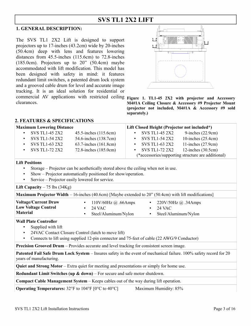
The SVS TL1 2X2 Lift is designed to support projectors up to 17-inches (43.2cm) wide by 20-inches (50.4cm) deep with lens and features lowering distances from 45.5-inches (115.6cm) to 72.8-inches (185.0cm). Projectors up to 20” (50.4cm) maybe accommodated with lift modification. This model has been designed with safety in mind: it features redundant limit switches, a patented drum lock system and a grooved cable drum for level and accurate image tracking. It is an ideal solution for residential or commercial AV applications with restricted ceiling clearances.
Figure 1. TL1-45 2X2 with projector and Accessory M4#1A Ceiling Closure & Accessory #9 Projector Mount (projector not included, M4#1A & Accessory #9 sold separately.)
2. FEATURES & SPECIFICATIONSMaximum Lowering Distance
• SVS TL1-45 2X2 45.5-inches (115.6cm)• SVS TL1-54 2X2 54.6-inches (138.7cm)• SVS TL1-63 2X2 63.7-inches (161.8cm)• SVS TL1-72 2X2 72.8-inches (185.0cm)
Lift Closed Height (Projector not included*)• SVS TL1-45 2X2 9-inches (22.9cm)• SVS TL1-54 2X2 10-inches (25.4cm)• SVS TL1-63 2X2 11-inches (27.9cm)• SVS TL1-72 2X2 12-inches (30.5cm)
(*accessories/supporting structure are additional)
Lift Positions• Storage – Projector can be aesthetically stored above the ceiling when not in use. • Show – Projector automatically positioned for show/operation.• Service – Projector easily lowered for service.
Lift Capacity – 75 lbs (34Kg)
Maximum Projector Width – 16-inches (40.6cm) [Maybe extended to 20” (50.4cm) with lift modifications]
Voltage/Current DrawLow Voltage ControlMaterial
• 110V/60Hz @ .66Amps• 24 VAC• Steel/Aluminum/Nylon
• 220V/50Hz @ .34Amps• 24 VAC• Steel/Aluminum/Nylon
Wall Plate Controller• Supplied with lift• 24VAC Contact Closure Control (latch to move lift)• Connects to lift using supplied 12-pin connector and 75-feet of cable (22 AWG/9 Conductor)
Precision Grooved Drum – Provides accurate and level tracking for consistent screen image.
Patented Fail Safe Drum Lock System – Insures safety in the event of mechanical failure. 100% safety record for 20 years of manufacturing.
Quiet and Strong Motor – Extra quiet for meeting and presentations or simply for home use.
Redundant Limit Switches (up & down) – For secure and safe motor shutdown.
Compact Cable Management System – Keeps cables out of the way during lift operation.
Operating Temperatures: 32°F to 104°F [0°C to 40°C] Maximum Humidity: 85%
SVS TL1 2X2 Lift Installation Instructions Page 3 of 16

3. SVS TL1 LIFT WARRANTY
SVS, Inc.'s limited warranty only covers failures due to defects in materials or workmanship that occur during normal use. This limited warranty DOES NOT cover failures resulting from accident, misuse, abuse, neglect, mishandling, faulty or improper installation and set-up adjustments, improper maintenance or alteration. Specific product warranties are as follows:
A 5-year parts and 90-day factory labor warranty applies to the following SVS products:
• All scissors style lifts• Accessory #11 Extra Show Position• Accessory #14 Floor Access Motor Control• Accessory #15 12-Volt Trigger
A 1-year parts and 90-day factory labor warranty applies to the following SVS products:
• All Motors• Accessory #1 Ceiling Closure• FP1 Closure Panel• M4#1A Ceiling Closure• Accessory #2 Plenum Shroud• Accessory #9 Projector Mount• Accessory #10 Dual Stack Projector Mount• Accessory #13 Platforms
A Return Material Authorization (RMA) number must be received from SVS prior to the return of any product. Products returned to SVS must be shipped adequately insured with freight prepaid and the RMA number clearly noted on the shipping label and crate. Items received freight collect or without RMA numbers clearly noted will be refused. Lift model, serial number, and proof of original purchase date may be required before warranty performance is rendered.
SVS TL1 2X2 Lift Installation Instructions Page 4 of 16

IMPORTANT: PLEASE READ THROUGH ALL INSTRUCTIONS (INCLUDING ACCESORY INSTRUCTIONS) BEFORE BEGINNING YOUR INSTALLATION.
This lift is designed to be used with a Wall Plate Controller, either automatically or manually controlled and will function without any special training in the “Show” mode. The Wall Plate Controller features a key switch which can be placed in the “Show” or “Auto” positions for normal operation. The “Off” position disables the Lift. The “Service” position must be used only by trained technical personnel when the Lift is lowered to floor level for service/access.
Note: The “Auto” position on the Wall Plate Controller is for Accessory #4 Power Sensor, Accessory #5 Power Sensor with Screen Control, and Accessory #15 12-Volt Trigger only
WARNINGTo prevent personal injury and property damage when servicing any part of the Lift drive system (electric motor/brake, drive chain/sprockets, steel lift cables, and/or drum lock assembly) the projector must be removed and the Lift's lower frame supported by straps, chain, or cable to prevent it from lowering unexpectedly while the drive system is being serviced.
IMPORTANTIf an Accessory #2 Plenum Shroud is to be installed with the Lift. Please read the Accessory Installation Instructions before beginning your installation. The Lift support structure will need to allow enough space to install the mounting hardware for the Plenum Shroud.
TO AVOID CABLE SPILLS• Do not push the Lift bottom frame upwards once the lift has been installed.• Make sure that there are no obstructions in the Lifts path. If the bottom frame is lowered onto an
obstruction the cable will slack and spill over the cable drum.
4. PRELIMINARY INSTALLATION CHECKS
• SVS recommends that the Lift support structure holds at least four (4) times the weight of the Lift and projector combined. You should always follow your local building codes.
• Required space for the Lift, projector, and accessories should be considered prior to installation. Check for obstructions that may prevent the Lift or accessories from being installed or operated.
• Plan for necessary Lift low voltage control cabling, projector audio/video/control cabling, and power connections.
• Do not install the projector on the Lift until the Lift, hardware, and any accessories have been properly installed and are operational.
• This Lift has been adjusted with cables tightly packed on the cable drum and leveled for precise tracking prior to being shipped from the factory. Do not remove the lift's shipping blocks until instructed to do so in Section 7. SVS scissor lifts are shipped in a slightly open position to eliminate stress on the limit switches and to maintain a tight cable pack on the cable drum. If physical height measurements are taken before the blocks are removed from the Lift, they may not accurately reflect the height of the closed Lift.
• All weight attached to the Lift must be centered between the Lift's cables. The balance point of the projector should be placed in line with the Lift cables (+/- 1-inch). If this is not possible you may need to counter weight the Lift to keep the Lift level.
• For ease of installation the Lift can be hoisted into the ceiling location with blocks and tackle, or by using a ratchet puller.
SVS TL1 2X2 Lift Installation Instructions Page 5 of 16
• As a reminder, clear all persons and obstructions from the Lift's path during its operation. Keep fingers and other objects away from the scissors and other moving parts. Technical personnel should always be present whenever the Lift is in the Service mode.
5. CONSIDERATION FOR LIFT PLACEMENT
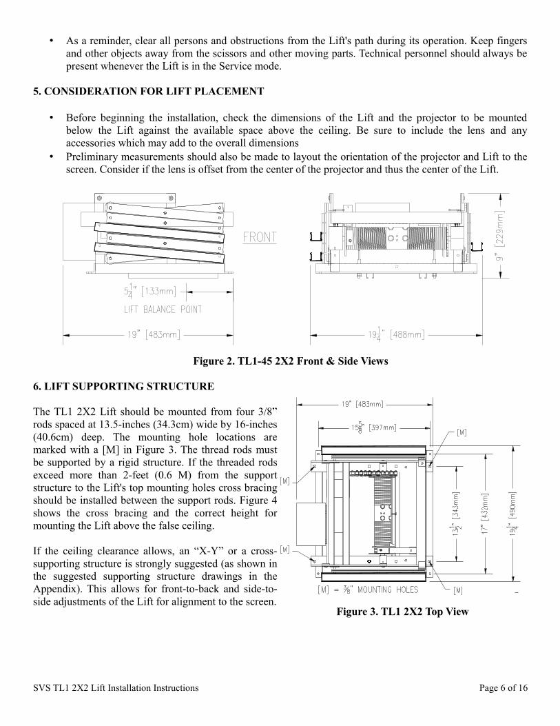
• Before beginning the installation, check the dimensions of the Lift and the projector to be mounted below the Lift against the available space above the ceiling. Be sure to include the lens and any accessories which may add to the overall dimensions
• Preliminary measurements should also be made to layout the orientation of the projector and Lift to the screen. Consider if the lens is offset from the center of the projector and thus the center of the Lift.
6. LIFT SUPPORTING STRUCTURE
The TL1 2X2 Lift should be mounted from four 3/8” rods spaced at 13.5-inches (34.3cm) wide by 16-inches (40.6cm) deep. The mounting hole locations are marked with a [M] in Figure 3. The thread rods must be supported by a rigid structure. If the threaded rods exceed more than 2-feet (0.6 M) from the support structure to the Lift's top mounting holes cross bracing should be installed between the support rods. Figure 4 shows the cross bracing and the correct height for mounting the Lift above the false ceiling.
If the ceiling clearance allows, an “X-Y” or a cross-supporting structure is strongly suggested (as shown in the suggested supporting structure drawings in the Appendix). This allows for front-to-back and side-to-side adjustments of the Lift for alignment to the screen.
SVS TL1 2X2 Lift Installation Instructions Page 6 of 16
Figure 2. TL1-45 2X2 Front & Side Views
Figure 3. TL1 2X2 Top View

Figure 4. Correct Height & Cross Bracing
SVS TL1 2X2 Lift Installation Instructions Page 7 of 16
Figure 5a. Flat Ceiling Support Structure
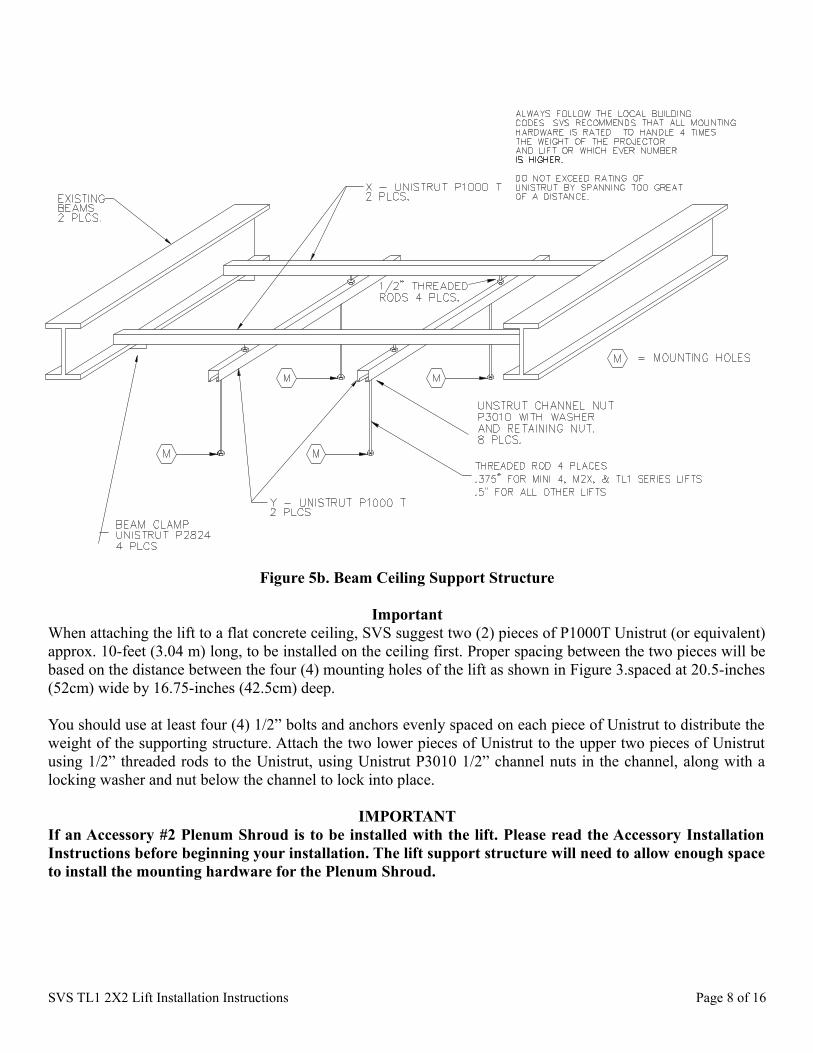
ImportantWhen attaching the lift to a flat concrete ceiling, SVS suggest two (2) pieces of P1000T Unistrut (or equivalent) approx. 10-feet (3.04 m) long, to be installed on the ceiling first. Proper spacing between the two pieces will be based on the distance between the four (4) mounting holes of the lift as shown in Figure 3.spaced at 20.5-inches (52cm) wide by 16.75-inches (42.5cm) deep.
You should use at least four (4) 1/2” bolts and anchors evenly spaced on each piece of Unistrut to distribute the weight of the supporting structure. Attach the two lower pieces of Unistrut to the upper two pieces of Unistrut using 1/2” threaded rods to the Unistrut, using Unistrut P3010 1/2” channel nuts in the channel, along with a locking washer and nut below the channel to lock into place.
IMPORTANTIf an Accessory #2 Plenum Shroud is to be installed with the lift. Please read the Accessory Installation Instructions before beginning your installation. The lift support structure will need to allow enough space to install the mounting hardware for the Plenum Shroud.
SVS TL1 2X2 Lift Installation Instructions Page 8 of 16
Figure 5b. Beam Ceiling Support Structure

7. LIFT INSTALLATION
a. Preparation:1. The Lift is shipped in a wooden crate.2. Do not remove the Lift from the crate until you are ready to install it.3. The Installation Instructions, Wall Plate Controller with control cable, and projector mounting hardware
are located in a cardboard box inside the crate.4. Unbolt the Lift from the bottom of the crate to remove the Lift from the crate.
b. Installing the Lift in the Ceiling
1. Raise the Lift into the ceiling and line up the four (4) mounting holes in the Lift's top frame with the 3/8” threaded rods of the supporting structure. Make sure that there is a top nut and a flat washer on each threaded rod before the Lift is mounted. See Figure 5. (Plenum Shrouds require additional hardware installed on the threaded rods before the Lift.)
2. Once the Lift's top frame has been inserted, add a hexnut to each threaded rod below the Lift frame. Always leave the top nut loose to allow adjustments until the Lift is leveled.
3. Level the Lift's top frame side-to-side and front-to-back using the lower hexnuts on the threaded rods. 4. Once the Lift is leveled, secure the Lift to the threaded rods by tightening the upper hexnuts. Do not
over tighten the fasteners as it could distort the top frame of the Lift.5. If the Power Sensor is used, please refer to the Power Sensor Instructions, otherwise, plug in the 12-pin
connector of the Wall Plate Controller into the 12-pin socket on the Lift's gray electrical box mounted on the rear of the Lift. The Wall Plate Controller includes 75-feet of cable and is shipped with the Lift. It is located in the cardboard box attached to the lid of the Lift's shipping crate.
6. Once the Lift is properly installed in the ceiling and leveled, you can remove the shipping blocks. Remove the blocks by removing the screws and tie-raps holding them in place.
TO AVOID CABLE SPILLS• Do not push the Lift bottom frame upwards once the Lift has been installed.• Make sure that there are no obstructions in the Lift's path. If the bottom frame is lowered onto an
obstruction the cable will slack and spill over the cable drum. If the cable spills over the cable drum and the Lift is not stopped the cable will back-wind onto the cable drum causing severe damage to the Lift and accessories.
SVS TL1 2X2 Lift Installation Instructions Page 9 of 16
Figure 6. Lift Mounting Hardware
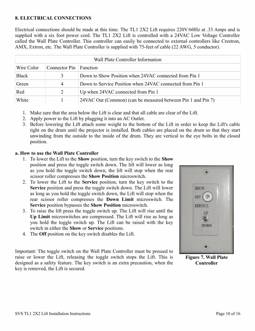
8. ELECTRICAL CONNECTIONS
Electrical connections should be made at this time. The TL1 2X2 Lift requires 220V/60Hz at .33 Amps and is supplied with a six foot power cord. The TL1 2X2 Lift is controlled with a 24VAC Low Voltage Controller called the Wall Plate Controller. This controller can easily be connected to external controllers like Crestron, AMX, Extron, etc. The Wall Plate Controller is supplied with 75-feet of cable (22 AWG, 5 conductor).
Wall Plate Controller InformationWire Color Connector Pin FunctionBlack 3 Down to Show Position when 24VAC connected from Pin 1Green 4 Down to Service Position when 24VAC connected from Pin 1Red 2 Up when 24VAC connected from Pin 1White 1 24VAC Out (Common) (can be measured between Pin 1 and Pin 7)
1. Make sure that the area below the Lift is clear and that all cable are clear of the Lift.2. Apply power to the Lift by plugging it into an AC Outlet.3. Before lowering the Lift attach some weight to the bottom of the Lift in order to keep the Lift's cable
tight on the drum until the projector is installed. Both cables are placed on the drum so that they start unwinding from the outside to the inside of the drum. They are vertical to the eye bolts in the closed position.
a. How to use the Wall Plate Controller1. To lower the Lift to the Show position, turn the key switch to the Show
position and press the toggle switch down. The lift will lower as long as you hold the toggle switch down, the lift will stop when the rear scissor roller compresses the Show Position microswitch.
2. To lower the Lift to the Service position, turn the key switch to the Service position and press the toggle switch down. The Lift will lower as long as you hold the toggle switch down, the Lift will stop when the rear scissor roller compresses the Down Limit microswitch. The Service position bypasses the Show Position microswitch.
3. To raise the lift press the toggle switch up. The Lift will rise until the Up Limit microswitches are compressed. The Lift will rise as long as you hold the toggle switch up. The Lift can be raised with the key switch in either the Show or Service positions.
4. The Off position on the key switch disables the Lift.
Important: The toggle switch on the Wall Plate Controller must be pressed to raise or lower the Lift, releasing the toggle switch stops the Lift. This is designed as a safety feature. The key switch is an extra precaution, when the key is removed, the Lift is secured.
SVS TL1 2X2 Lift Installation Instructions Page 10 of 16
Figure 7. Wall Plate Controller
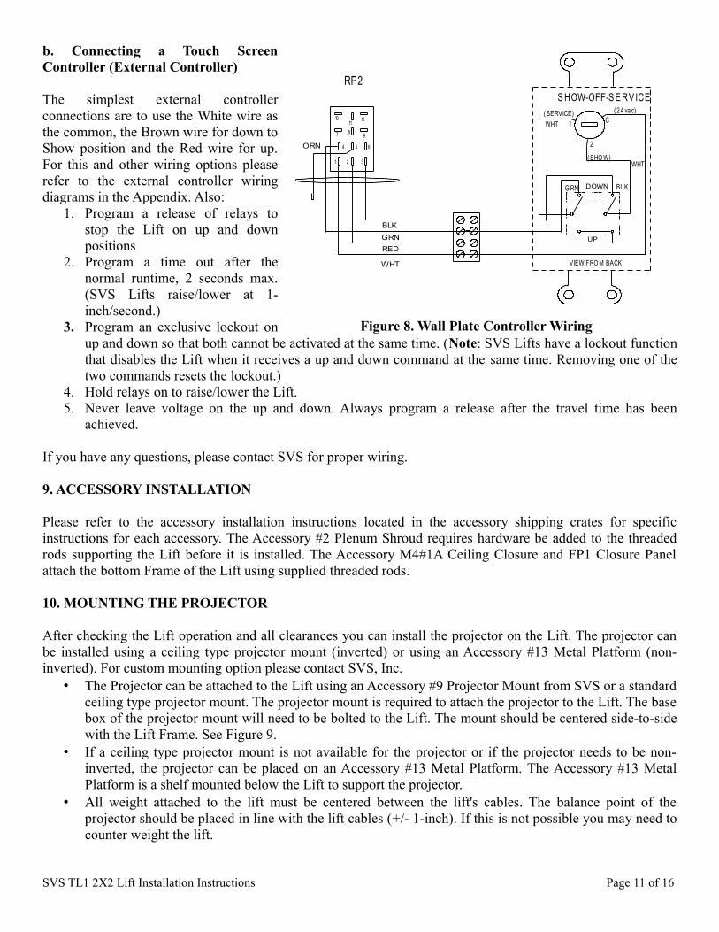
b. Connecting a Touch Screen Controller (External Controller)
The simplest external controller connections are to use the White wire as the common, the Brown wire for down to Show position and the Red wire for up. For this and other wiring options please refer to the external controller wiring diagrams in the Appendix. Also:
1. Program a release of relays to stop the Lift on up and down positions
2. Program a time out after the normal runtime, 2 seconds max. (SVS Lifts raise/lower at 1-inch/second.)
3. Program an exclusive lockout on up and down so that both cannot be activated at the same time. (Note: SVS Lifts have a lockout function that disables the Lift when it receives a up and down command at the same time. Removing one of the two commands resets the lockout.)
4. Hold relays on to raise/lower the Lift.5. Never leave voltage on the up and down. Always program a release after the travel time has been
achieved.
If you have any questions, please contact SVS for proper wiring.
9. ACCESSORY INSTALLATION
Please refer to the accessory installation instructions located in the accessory shipping crates for specific instructions for each accessory. The Accessory #2 Plenum Shroud requires hardware be added to the threaded rods supporting the Lift before it is installed. The Accessory M4#1A Ceiling Closure and FP1 Closure Panel attach the bottom Frame of the Lift using supplied threaded rods.
10. MOUNTING THE PROJECTOR
After checking the Lift operation and all clearances you can install the projector on the Lift. The projector can be installed using a ceiling type projector mount (inverted) or using an Accessory #13 Metal Platform (non-inverted). For custom mounting option please contact SVS, Inc.
• The Projector can be attached to the Lift using an Accessory #9 Projector Mount from SVS or a standard ceiling type projector mount. The projector mount is required to attach the projector to the Lift. The base box of the projector mount will need to be bolted to the Lift. The mount should be centered side-to-side with the Lift Frame. See Figure 9.
• If a ceiling type projector mount is not available for the projector or if the projector needs to be non-inverted, the projector can be placed on an Accessory #13 Metal Platform. The Accessory #13 Metal Platform is a shelf mounted below the Lift to support the projector.
• All weight attached to the lift must be centered between the lift's cables. The balance point of the projector should be placed in line with the lift cables (+/- 1-inch). If this is not possible you may need to counter weight the lift.
SVS TL1 2X2 Lift Installation Instructions Page 11 of 16
Figure 8. Wall Plate Controller Wiring
VIEW FRO M BACK
RP2S HOW-OFF-S E RV ICE
DOWN
WHT
WHT
WHT
ORN
BLK
UPREDGRN
BL KG RN
1
2
C( SERVICE)
( SHO W)
( 2 4 va c)10
11 12
7 8 9
654
1 2 3

Leveling the Projector• If the projector can not be leveled using the projector mount adjustments, you can make fine adjustments
to the Lift.• Level corrections are made with the projector mounted after confirming that the cable is packed tightly
and is straight on the Cable Drum.• It is best to lower the lift to the Service position and then completely up before leveling the projector.• Level adjustments should be made with the projector in the Show position.• Position a level across the front of the projector. Fine adjustments are done by adjusting the nuts on the
bottom of the cable eye bolts. Raise and lower the Lift until satisfactory level is achieved.• After adjustments are made tighten the eye bolt nuts.
11. CABLE MANAGEMENT
The SVS TL1 2X2 Lifts feature Compact Cable Management installed on the side of the Lift. These cable trays and covers are used to keep the projector cables clear of the Lift's moving parts during Lift operation. To keep the projector cables clear of the scissors please attach the cables as shown in the Figure 10. Place the projector cables into the cable trays, wrapping the cables around the Lift. Place the ty-raps at the ends of the cable tray to secure the cables and snap the cable tray covers in place.
SVS TL1 2X2 Lift Installation Instructions Page 12 of 16
Figure 9. Projector Mounting
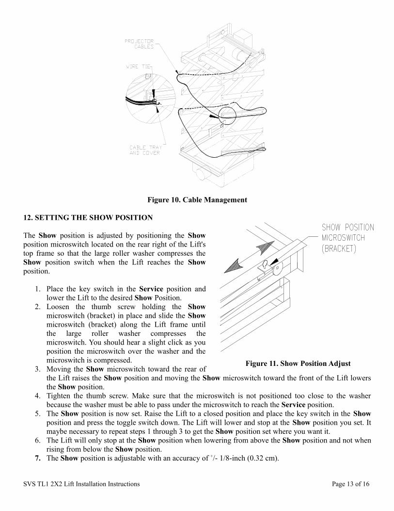
12. SETTING THE SHOW POSITION
The Show position is adjusted by positioning the Show position microswitch located on the rear right of the Lift's top frame so that the large roller washer compresses the Show position switch when the Lift reaches the Show position.
1. Place the key switch in the Service position and lower the Lift to the desired Show Position.
2. Loosen the thumb screw holding the Show microswitch (bracket) in place and slide the Show microswitch (bracket) along the Lift frame until the large roller washer compresses the microswitch. You should hear a slight click as you position the microswitch over the washer and the microswitch is compressed.
3. Moving the Show microswitch toward the rear of the Lift raises the Show position and moving the Show microswitch toward the front of the Lift lowers the Show position.
4. Tighten the thumb screw. Make sure that the microswitch is not positioned too close to the washer because the washer must be able to pass under the microswitch to reach the Service position.
5. The Show position is now set. Raise the Lift to a closed position and place the key switch in the Show position and press the toggle switch down. The Lift will lower and stop at the Show position you set. It maybe necessary to repeat steps 1 through 3 to get the Show position set where you want it.
6. The Lift will only stop at the Show position when lowering from above the Show position and not when rising from below the Show position.
7. The Show position is adjustable with an accuracy of +/- 1/8-inch (0.32 cm).
SVS TL1 2X2 Lift Installation Instructions Page 13 of 16
Figure 11. Show Position Adjust
Figure 10. Cable Management

13. MAINTENANCE
• Inspect the Lift occasionally for any loose bolts or cable clamps. The scissor bolts are adjusted for no slack, but must not be too tight. If scissor bolts are found loose, tighten to approximately 151 lbs torque, the back off 1/8-inch. These bolts have nylon locking nuts and should stay at this position.
• Check Lift and projector cables for damage or wear.• That the Drum arm is being held up by the Drum Lock Spring.• Check the Drum Lock pawl (white nylon piece) located on the Cable Drum. The pawl should move
freely and drop when when it reaches the top of the Cable Drum's rotation, avoiding contact with the Drum Lock arm. If the drum rotates too fast, the pawl will swing out and catch the arm, locking the drum after the first rotation.
• The Cable Drum Bearings (pillow block bearings) are pre-lubricated and do not require attention.• The Lift motor does not require attention.• If the magnetic brake (part of the Lift motor) does not hold properly, it should be replaced immediately.
WARNINGTo prevent personal injury and property damage when servicing any part of the lift drive system (electric motor/brake, drive chain/sprockets, steel lift cables, and/or drum lock assembly) the projector must be removed and the lift's lower frame supported by straps, chain, or cable to prevent it from lowering unexpectedly while the drive system is being serviced.
Figure 12. Lift Parts Locations
SVS TL1 2X2 Lift Installation Instructions Page 14 of 16
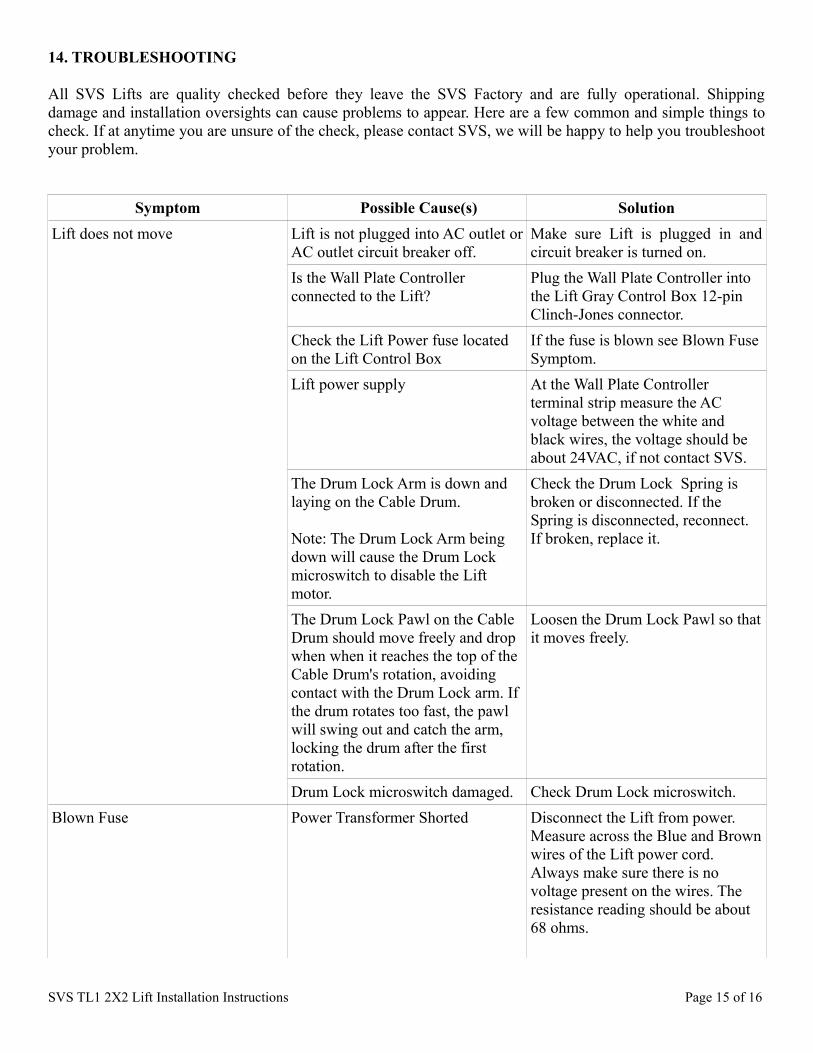
14. TROUBLESHOOTING
All SVS Lifts are quality checked before they leave the SVS Factory and are fully operational. Shipping damage and installation oversights can cause problems to appear. Here are a few common and simple things to check. If at anytime you are unsure of the check, please contact SVS, we will be happy to help you troubleshoot your problem.
Symptom Possible Cause(s) SolutionLift does not move Lift is not plugged into AC outlet or
AC outlet circuit breaker off.Make sure Lift is plugged in and circuit breaker is turned on.
Is the Wall Plate Controller connected to the Lift?
Plug the Wall Plate Controller into the Lift Gray Control Box 12-pin Clinch-Jones connector.
Check the Lift Power fuse located on the Lift Control Box
If the fuse is blown see Blown Fuse Symptom.
Lift power supply At the Wall Plate Controller terminal strip measure the AC voltage between the white and black wires, the voltage should be about 24VAC, if not contact SVS.
The Drum Lock Arm is down and laying on the Cable Drum.
Note: The Drum Lock Arm being down will cause the Drum Lock microswitch to disable the Lift motor.
Check the Drum Lock Spring is broken or disconnected. If the Spring is disconnected, reconnect. If broken, replace it.
The Drum Lock Pawl on the Cable Drum should move freely and drop when when it reaches the top of the Cable Drum's rotation, avoiding contact with the Drum Lock arm. If the drum rotates too fast, the pawl will swing out and catch the arm, locking the drum after the first rotation.
Loosen the Drum Lock Pawl so that it moves freely.
Drum Lock microswitch damaged. Check Drum Lock microswitch.Blown Fuse Power Transformer Shorted Disconnect the Lift from power.
Measure across the Blue and Brown wires of the Lift power cord. Always make sure there is no voltage present on the wires. The resistance reading should be about 68 ohms.
SVS TL1 2X2 Lift Installation Instructions Page 15 of 16
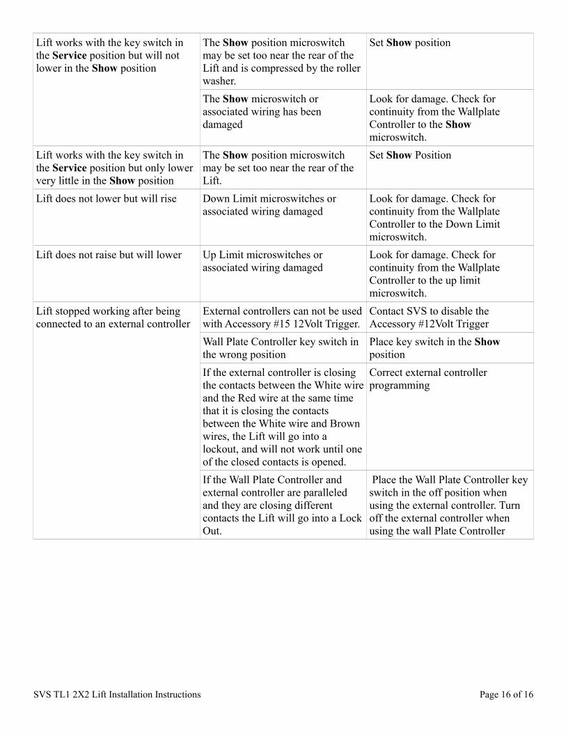
Lift works with the key switch in the Service position but will not lower in the Show position
The Show position microswitch may be set too near the rear of the Lift and is compressed by the roller washer.
Set Show position
The Show microswitch or associated wiring has been damaged
Look for damage. Check for continuity from the Wallplate Controller to the Show microswitch.
Lift works with the key switch in the Service position but only lower very little in the Show position
The Show position microswitch may be set too near the rear of the Lift.
Set Show Position
Lift does not lower but will rise Down Limit microswitches or associated wiring damaged
Look for damage. Check for continuity from the Wallplate Controller to the Down Limit microswitch.
Lift does not raise but will lower Up Limit microswitches or associated wiring damaged
Look for damage. Check for continuity from the Wallplate Controller to the up limit microswitch.
Lift stopped working after being connected to an external controller
External controllers can not be used with Accessory #15 12Volt Trigger.
Contact SVS to disable the Accessory #12Volt Trigger
Wall Plate Controller key switch in the wrong position
Place key switch in the Show position
If the external controller is closing the contacts between the White wire and the Red wire at the same time that it is closing the contacts between the White wire and Brown wires, the Lift will go into a lockout, and will not work until one of the closed contacts is opened.
Correct external controller programming
If the Wall Plate Controller and external controller are paralleled and they are closing different contacts the Lift will go into a Lock Out.
Place the Wall Plate Controller key switch in the off position when using the external controller. Turn off the external controller when using the wall Plate Controller
SVS TL1 2X2 Lift Installation Instructions Page 16 of 16


![Svs Agencies[1]](https://img.pdfslide.us/doc/110x75/577cc7a71a28aba711a191e1/svs-agencies1.jpg)