Embed Size (px)
Citation preview
T H E E S A B W E L D I N G A N D C U T T I N G J O U R N A L V O L . 5 7 N O . 2 2 0 0 2
Advanced Materials
Advanced Materials
Contents Vol. 57 No. 2 2002
Articles in Svetsaren may be reproduced without permission but with an acknowledgement to ESAB.
PublisherBertil Pekkari
EditorBen Altemühl
Editorial committeeKlas Weman, Björn Torstensson, Johnny Sundin, Johan Elvander, Lars-Erik Stridh,
Lars-Göran Eriksson, Uwe Mayer, Manfred Funccius, Dave Meyer, Donna Terry, Tony Anderson
AddressESAB AB, Box 8004, SE-402 77 Göteborg, Sweden
Internet addresshttp://www.esab.comE-mail: [email protected]
Lay-out: Duco Messie, Printed in the Netherlands
THE ESAB WELDING AND CUTTING JOURNAL VOL. 57 NO.2 2002
Advanced Materials
High deposition welding of Francis turbinerunners for the Three Gorges dam project.The article informs about the world's largesthydro power project ever, and describesESAB's involvement in the welding of theFrancis turbine runners.
Welding of copper-nickel alloys at KvaernerMasa-Yards.The orbital TIG welding of copper-nickelalloy pipes as an alternative to brazing.
Friction Stir Welding- progress in R&D andnew applicationsThe article presents recent R&D results, anew machine series, and a fascinating newapplication in the welding of thick copper.
Welding of supermartensitic stainless steels.The orbital narrow gap girth welding of pipesand the dissimilar joining of supermartensiticand superduplex pipes.
Chicago Bridge & Iron Company meetschallenge of stainless steel welding forcryogenic rocket fuel tanksThe welding of cryogenic storage tanks forthe Boeing Space Launch Complex 37 atCape Canaveral Air Force Station.
Welding high strength pipelines - fromlaboratory to field.A survey of the developments in the mecha-nised GMAW of pipelines in X80 type highstrength steel.
Synergic Cold Wire submerged arc weldingResults of research on the application of thisnew, cost-efficient welding process to stainlesssteel.
Welding tramway rails in BucharestA report on the use of ESAB's enclosed weld-ing technique for the joining of tramway rails.
The mechanised MAG welding of the Clarenatural gas line.The use of OK 12.65 copper-free wire in themechanised GMAW of a new extension ofthe Irish national gas grid.
Consumable development for oxidisingchloride containing process environments.Research work at VTT Technical ResearchCentre in Finland.
CIMTAS, an international player in powergeneration and energy storage.The article reviews CIMTAS, a Turkishfabricator of power plants and other energyrelated constructions. The fabrication of twovery large LNG tanks is highlighted.
Stubends & SpatterShort news
3
9
11
14
21
22
26
32
39
45
50
36
Svetsaren no. 2 • 2002 • 3
High deposition welding of Francis turbine runners for the Three Gorges dam projectBy: Nils Thalberg, Solveig Rigdal, Leif Karlsson, John van den Broek and Herbert Kaufmann, ESAB AB
This paper was originally presented at the Stainless Steel World America 2002 Conference.
The world’s largest hydroelectric project, the Three Gorges dam in China, willcomprise 26 Francis turbines for the production of electricity. Each turbine runneris 10m in diameter, weighs 450 tonnes and will generate 700 MW. The runnersare made of solid 410 NiMo type martensitic stainless steel (13% Cr, 4% Ni, 0.5%Mo) castings. Welding is used for the assembly and repair of casting defects.ESAB is involved in the production of the runners with consumables andequipment for SAW and GMAW.
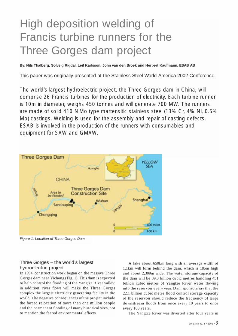
Three Gorges – the world’s largesthydroelectric project In 1994, construction work began on the massive ThreeGorges dam near Yichang (Fig. 1). This dam is expectedto help control the flooding of the Yangtze River valley;in addition, river flows will make the Three Gorgescomplex the largest electricity generating facility in theworld. The negative consequences of the project includethe forced relocation of more than one million peopleand the permanent flooding of many historical sites, notto mention the feared environmental effects.
Figure 1. Location of Three Gorges Dam.
A lake about 650km long with an average width of1.1km will form behind the dam, which is 185m highand about 2,309m wide. The water storage capacity ofthe dam will be 39.3 billion cubic metres handling 451billion cubic metres of Yangtze River water flowinginto the reservoir every year. Dam sponsors say that the22.1 billion cubic metre flood control storage capacityof the reservoir should reduce the frequency of largedownstream floods from once every 10 years to onceevery 100 years.
The Yangtze River was diverted after four years in
4 • Svetsaren no. 2 • 2002
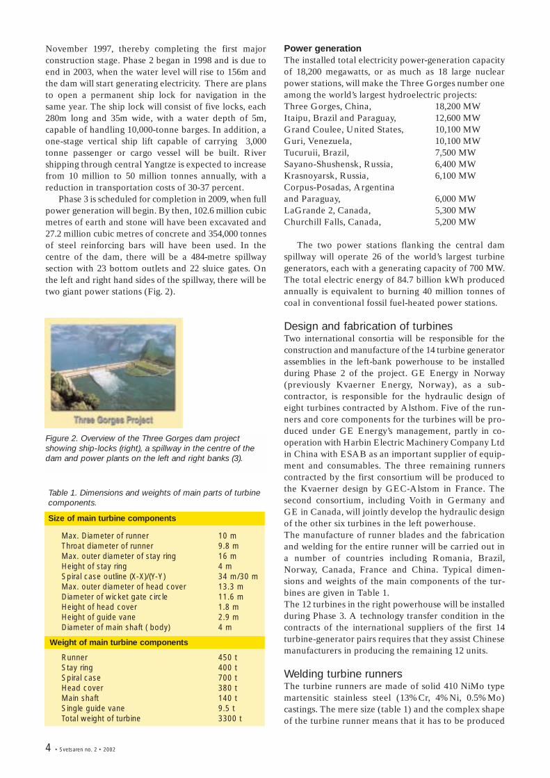
Figure 2. Overview of the Three Gorges dam projectshowing ship-locks (right), a spillway in the centre of thedam and power plants on the left and right banks (3).
Table 1. Dimensions and weights of main parts of turbinecomponents.
Size of main turbine components
Max. Diameter of runner 10 mThroat diameter of runner 9.8 mMax. outer diameter of stay ring 16 mHeight of stay ring 4 mSpiral case outline (X-X)/(Y-Y) 34 m/30 mMax. outer diameter of head cover 13.3 mDiameter of wicket gate circle 11.6 mHeight of head cover 1.8 mHeight of guide vane 2.9 mDiameter of main shaft ( body) 4 m
Weight of main turbine components
Runner 450 tStay ring 400 tSpiral case 700 tHead cover 380 tMain shaft 140 tSingle guide vane 9.5 tTotal weight of turbine 3300 t
November 1997, thereby completing the first majorconstruction stage. Phase 2 began in 1998 and is due toend in 2003, when the water level will rise to 156m andthe dam will start generating electricity. There are plansto open a permanent ship lock for navigation in thesame year. The ship lock will consist of five locks, each280m long and 35m wide, with a water depth of 5m,capable of handling 10,000-tonne barges. In addition, aone-stage vertical ship lift capable of carrying 3,000tonne passenger or cargo vessel will be built. Rivershipping through central Yangtze is expected to increasefrom 10 million to 50 million tonnes annually, with areduction in transportation costs of 30-37 percent.
Phase 3 is scheduled for completion in 2009, when fullpower generation will begin. By then, 102.6 million cubicmetres of earth and stone will have been excavated and27.2 million cubic metres of concrete and 354,000 tonnesof steel reinforcing bars will have been used. In thecentre of the dam, there will be a 484-metre spillwaysection with 23 bottom outlets and 22 sluice gates. Onthe left and right hand sides of the spillway, there will betwo giant power stations (Fig. 2).
Power generationThe installed total electricity power-generation capacityof 18,200 megawatts, or as much as 18 large nuclearpower stations, will make the Three Gorges number oneamong the world’s largest hydroelectric projects:Three Gorges, China, 18,200 MWItaipu, Brazil and Paraguay, 12,600 MWGrand Coulee, United States, 10,100 MWGuri, Venezuela, 10,100 MWTucuruii, Brazil, 7,500 MWSayano-Shushensk, Russia, 6,400 MWKrasnoyarsk, Russia, 6,100 MWCorpus-Posadas, Argentina and Paraguay, 6,000 MWLaGrande 2, Canada, 5,300 MWChurchill Falls, Canada, 5,200 MW
The two power stations flanking the central damspillway will operate 26 of the world’s largest turbinegenerators, each with a generating capacity of 700 MW.The total electric energy of 84.7 billion kWh producedannually is equivalent to burning 40 million tonnes ofcoal in conventional fossil fuel-heated power stations.
Design and fabrication of turbinesTwo international consortia will be responsible for theconstruction and manufacture of the 14 turbine generatorassemblies in the left-bank powerhouse to be installedduring Phase 2 of the project. GE Energy in Norway(previously Kvaerner Energy, Norway), as a sub-contractor, is responsible for the hydraulic design ofeight turbines contracted by Alsthom. Five of the run-ners and core components for the turbines will be pro-duced under GE Energy’s management, partly in co-operation with Harbin Electric Machinery Company Ltdin China with ESAB as an important supplier of equip-ment and consumables. The three remaining runnerscontracted by the first consortium will be produced tothe Kvaerner design by GEC-Alstom in France. Thesecond consortium, including Voith in Germany andGE in Canada, will jointly develop the hydraulic designof the other six turbines in the left powerhouse. The manufacture of runner blades and the fabricationand welding for the entire runner will be carried out ina number of countries including Romania, Brazil,Norway, Canada, France and China. Typical dimen-sions and weights of the main components of the tur-bines are given in Table 1.The 12 turbines in the right powerhouse will be installedduring Phase 3. A technology transfer condition in thecontracts of the international suppliers of the first 14turbine-generator pairs requires that they assist Chinesemanufacturers in producing the remaining 12 units.
Welding turbine runnersThe turbine runners are made of solid 410 NiMo typemartensitic stainless steel (13%Cr, 4%Ni, 0.5%Mo)castings. The mere size (table 1) and the complex shapeof the turbine runner means that it has to be produced
Svetsaren no. 2 • 2002 • 5
from a number of smaller (yet still impressively sized)castings. Welding is used to join the separate castingsand repair the casting defects. A combination ofdifferent welding techniques, including manual metalarc welding (MMA), semi-automatic techniques suchas gas metal arc welding (GMAW) with solid or coredwires and fully-mechanised welding with submergedarc welding (SAW), is being used. The specific choice ofmethod varies depending on factors such as jointgeometry, accessibility and the cost of labour,equipment and consumables. Different combinationsof welding techniques and consumables will thereforebe used for different turbine runners depending onlocation and the responsible company.
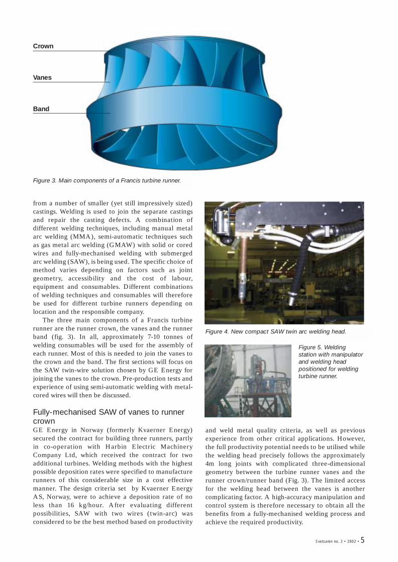
The three main components of a Francis turbinerunner are the runner crown, the vanes and the runnerband (fig. 3). In all, approximately 7-10 tonnes ofwelding consumables will be used for the assembly ofeach runner. Most of this is needed to join the vanes tothe crown and the band. The first sections will focus onthe SAW twin-wire solution chosen by GE Energy forjoining the vanes to the crown. Pre-production tests andexperience of using semi-automatic welding with metal-cored wires will then be discussed.
Fully-mechanised SAW of vanes to runnercrownGE Energy in Norway (formerly Kvaerner Energy)secured the contract for building three runners, partlyin co-operation with Harbin Electric MachineryCompany Ltd, which received the contract for twoadditional turbines. Welding methods with the highestpossible deposition rates were specified to manufacturerunners of this considerable size in a cost effectivemanner. The design criteria set by Kvaerner EnergyAS, Norway, were to achieve a deposition rate of noless than 16 kg/hour. After evaluating differentpossibilities, SAW with two wires (twin-arc) wasconsidered to be the best method based on productivity
Figure 3. Main components of a Francis turbine runner.
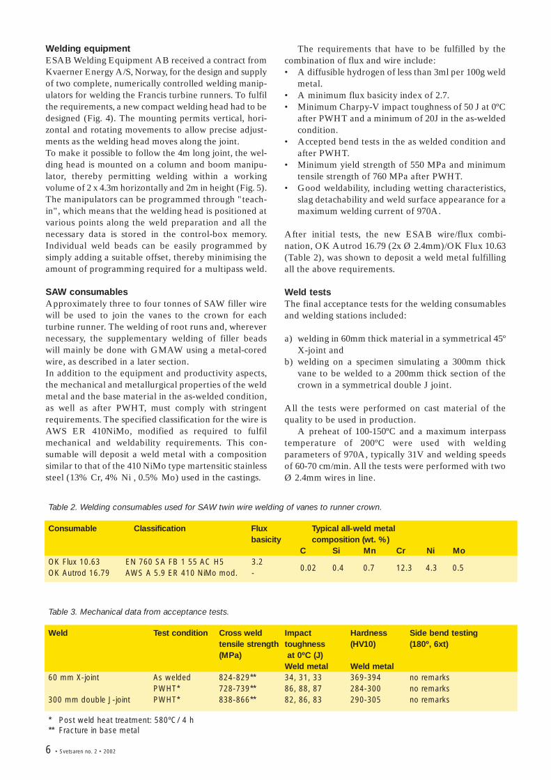
Figure 4. New compact SAW twin arc welding head.
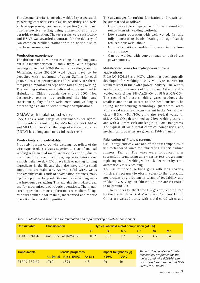
Figure 5. Weldingstation with manipulatorand welding headpositioned for weldingturbine runner.
and weld metal quality criteria, as well as previousexperience from other critical applications. However,the full productivity potential needs to be utilised whilethe welding head precisely follows the approximately4m long joints with complicated three-dimensionalgeometry between the turbine runner vanes and therunner crown/runner band (Fig. 3). The limited accessfor the welding head between the vanes is anothercomplicating factor. A high-accuracy manipulation andcontrol system is therefore necessary to obtain all thebenefits from a fully-mechanised welding process andachieve the required productivity.
Crown
Vanes
Band
6 • Svetsaren no. 2 • 2002
Welding equipmentESAB Welding Equipment AB received a contract fromKvaerner Energy A/S, Norway, for the design and supplyof two complete, numerically controlled welding manip-ulators for welding the Francis turbine runners. To fulfilthe requirements, a new compact welding head had to bedesigned (Fig. 4). The mounting permits vertical, hori-zontal and rotating movements to allow precise adjust-ments as the welding head moves along the joint.To make it possible to follow the 4m long joint, the wel-ding head is mounted on a column and boom manipu-lator, thereby permitting welding within a workingvolume of 2 x 4.3m horizontally and 2m in height (Fig. 5). The manipulators can be programmed through "teach-in", which means that the welding head is positioned atvarious points along the weld preparation and all thenecessary data is stored in the control-box memory.Individual weld beads can be easily programmed bysimply adding a suitable offset, thereby minimising theamount of programming required for a multipass weld.
SAW consumablesApproximately three to four tonnes of SAW filler wirewill be used to join the vanes to the crown for eachturbine runner. The welding of root runs and, wherevernecessary, the supplementary welding of filler beadswill mainly be done with GMAW using a metal-coredwire, as described in a later section. In addition to the equipment and productivity aspects,the mechanical and metallurgical properties of the weldmetal and the base material in the as-welded condition,as well as after PWHT, must comply with stringentrequirements. The specified classification for the wire isAWS ER 410NiMo, modified as required to fulfilmechanical and weldability requirements. This con-sumable will deposit a weld metal with a compositionsimilar to that of the 410 NiMo type martensitic stainlesssteel (13% Cr, 4% Ni , 0.5% Mo) used in the castings.
The requirements that have to be fulfilled by thecombination of flux and wire include:• A diffusible hydrogen of less than 3ml per 100g weld
metal.• A minimum flux basicity index of 2.7. • Minimum Charpy-V impact toughness of 50 J at 0ºC
after PWHT and a minimum of 20J in the as-weldedcondition.
• Accepted bend tests in the as welded condition andafter PWHT.
• Minimum yield strength of 550 MPa and minimumtensile strength of 760 MPa after PWHT.
• Good weldability, including wetting characteristics,slag detachability and weld surface appearance for amaximum welding current of 970A.
After initial tests, the new ESAB wire/flux combi-nation, OK Autrod 16.79 (2x Ø 2.4mm)/OK Flux 10.63(Table 2), was shown to deposit a weld metal fulfillingall the above requirements.
Weld testsThe final acceptance tests for the welding consumablesand welding stations included:
a) welding in 60mm thick material in a symmetrical 45ºX-joint and
b) welding on a specimen simulating a 300mm thickvane to be welded to a 200mm thick section of thecrown in a symmetrical double J joint.
All the tests were performed on cast material of thequality to be used in production.
A preheat of 100-150ºC and a maximum interpasstemperature of 200ºC were used with weldingparameters of 970A, typically 31V and welding speedsof 60-70 cm/min. All the tests were performed with twoØ 2.4mm wires in line.
Table 2. Welding consumables used for SAW twin wire welding of vanes to runner crown.
Consumable Classification Flux Typical all-weld metalbasicity composition (wt. %)
C Si Mn Cr Ni MoOK Flux 10.63 EN 760 SA FB 1 55 AC H5 3.2OK Autrod 16.79 AWS A 5.9 ER 410 NiMo mod. -
Table 3. Mechanical data from acceptance tests.
Weld Test condition Cross weld Impact Hardness Side bend testingtensile strength toughness (HV10) (180º, 6xt)(MPa) at 0ºC (J)
Weld metal Weld metal60 mm X-joint As welded 824-829** 34, 31, 33 369-394 no remarks
PWHT* 728-739** 86, 88, 87 284-300 no remarks300 mm double J-joint PWHT* 838-866** 82, 86, 83 290-305 no remarks
* Post weld heat treatment: 580ºC/ 4 h ** Fracture in base metal
0.02 0.4 0.7 12.3 4.3 0.5
Svetsaren no. 2 • 2002 • 7
The acceptance criteria included weldability aspects suchas wetting characteristics, slag detachability and weldsurface appearance, mechanical properties (Table 3) andnon-destructive testing using ultrasonic and radi-ographic examination. The test results were satisfactoryand ESAB was awarded a contract for the delivery oftwo complete welding stations with an option also topurchase consumables.
Production experienceThe thickness of the vane varies along the 4m long joint,but it is mainly between 70 and 220mm. With a typicalwelding current of 700-800A and a welding speed of70cm/min, some 200-300 weld beads have to bedeposited with heat inputs of about 2kJ/mm for eachjoint. Consistent performance and reliability are there-fore just as important as deposition rates during welding.The welding stations were delivered and assembled inHuludao in China towards the end of 2000. Nondestructive testing has confirmed the high andconsistent quality of the weld metal and welding isproceeding as planned without major complications.
GMAW with metal-cored wiresESAB has a wide range of consumables for hydro-turbine solutions, not only for SAW but also for GMAWand MMA. In particular, the range of metal-cored wires(MCW) has a long and successful track record.
Productivity and weldabilityProductivity from cored wire welding, regardless of thewire type used, is always superior to that of manualwelding with manual metal arc stick electrodes, due tothe higher duty cycle. In addition, deposition rates are ona much higher level. MCWs have little or no slag formingingredients in the fill and they also have only a smallamount of arc stabilisers. As with solid wires, weldsdisplay only small islands of de-oxidation products, mak-ing them popular for productive multi-run welding with-out inter-run de-slagging. This explains their widespreaduse for mechanised and robotic operations. The metal-cored types for turbine applications are medium filling-rate wires suitable for manual, mechanised and roboticoperation, in all welding positions.
The advantages for turbine fabrication and repair canbe summarised as follows. • High duty cycle compared with other manual and
semi-automatic welding methods. • Low spatter operation with well wetted, flat and
fully penetrating beads, leading to significantlyreduced post weld labour.
• Good all-positional weldability, even in the low-current range.
• Can be welded with conventional or pulsed arcpower sources.
Metal-cored wires for hydropower turbineapplicationsFILARC PZ6166 is a MCW which has been speciallydeveloped for welding 410 NiMo type martensiticstainless steel in the hydro power industry. The wire isavailable with diameters of 1.2 mm and 1.6 mm and iswelded with either 98%Ar/2%O2 or 98%Ar/2%CO2.The second of these shielding gases produces thesmallest amount of silicate on the bead surface. Therolling manufacturing technology guarantees wireswith a weld metal hydrogen content in the "extra low"class (HDM <5ml/100gram), the typical value in98%Ar/2%CO2 determined at 250A welding currentand with a 15mm stick-out length is < 3ml/100 grams.The typical all weld metal chemical composition andmechanical properties are given in Tables 4 and 5.
Fabrication of Francis runners GE Energy, Norway, was one of the first companies touse metal-cored wires for fabricating Francis turbinerunners (Fig. 6). The wires were introduced aftersuccessfully completing an extensive test programme,replacing manual welding with stick electrodes by semi-automatic GMAW welding. The use of special welding guns with long nozzles,which are necessary to obtain access to the joints, didnot present any problem in terms of feedability andweldability. Savings on fabrication time are estimatedto be around 30%.
The runners for the Three Gorges project producedby the Harbin Electrical Machinery Company Ltd inChina are welded partly with metal-cored wires and
Table 5. Metal cored wire used for fabrication and repair welding of turbine components.
Consumable Classification Typical all-weld metal composition (wt. %)
C Si Mn Cr Ni Mo
FILARC PZ6166 AWS 5.22 E410NiMo-T2~ 0.02 0.7 1.2 12.5 4.5 0.4
Consumable Tensile properties Impact toughness (J)
Rm (MPa) Rp0.2 (MPa) A5 (%) +20ºC -20ºC
FILARC PZ6166 >760 >570 >15 50 40
Table 4. Typical all-weld metalmechanical properties for themetal cored wire PZ6166 afterpost weld heat treatment at 580-600ºC for 8 hours.
8 • Svetsaren no. 2 • 2002
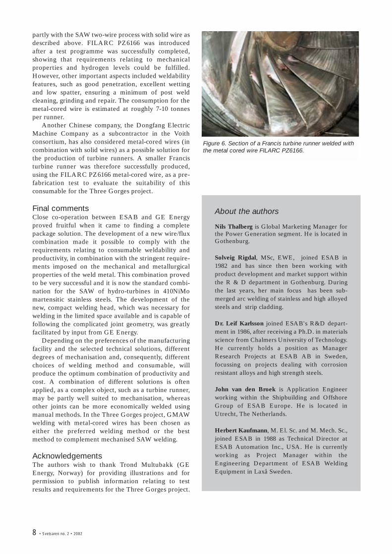
partly with the SAW two-wire process with solid wire asdescribed above. FILARC PZ6166 was introducedafter a test programme was successfully completed,showing that requirements relating to mechanicalproperties and hydrogen levels could be fulfilled.However, other important aspects included weldabilityfeatures, such as good penetration, excellent wettingand low spatter, ensuring a minimum of post weldcleaning, grinding and repair. The consumption for themetal-cored wire is estimated at roughly 7-10 tonnesper runner.
Another Chinese company, the Dongfang ElectricMachine Company as a subcontractor in the Voithconsortium, has also considered metal-cored wires (incombination with solid wires) as a possible solution forthe production of turbine runners. A smaller Francisturbine runner was therefore successfully produced,using the FILARC PZ6166 metal-cored wire, as a pre-fabrication test to evaluate the suitability of thisconsumable for the Three Gorges project.
Final commentsClose co-operation between ESAB and GE Energyproved fruitful when it came to finding a completepackage solution. The development of a new wire/fluxcombination made it possible to comply with therequirements relating to consumable weldability andproductivity, in combination with the stringent require-ments imposed on the mechanical and metallurgicalproperties of the weld metal. This combination provedto be very successful and it is now the standard combi-nation for the SAW of hydro-turbines in 410NiMomartensitic stainless steels. The development of thenew, compact welding head, which was necessary forwelding in the limited space available and is capable offollowing the complicated joint geometry, was greatlyfacilitated by input from GE Energy.
Depending on the preferences of the manufacturingfacility and the selected technical solutions, differentdegrees of mechanisation and, consequently, differentchoices of welding method and consumable, willproduce the optimum combination of productivity andcost. A combination of different solutions is oftenapplied, as a complex object, such as a turbine runner,may be partly well suited to mechanisation, whereasother joints can be more economically welded usingmanual methods. In the Three Gorges project, GMAWwelding with metal-cored wires has been chosen aseither the preferred welding method or the bestmethod to complement mechanised SAW welding.
AcknowledgementsThe authors wish to thank Trond Multubakk (GEEnergy, Norway) for providing illustrations and forpermission to publish information relating to testresults and requirements for the Three Gorges project.
Figure 6. Section of a Francis turbine runner welded withthe metal cored wire FILARC PZ6166.
About the authors
Nils Thalberg is Global Marketing Manager forthe Power Generation segment. He is located inGothenburg.
Solveig Rigdal, MSc, EWE, joined ESAB in1982 and has since then been working withproduct development and market support withinthe R & D department in Gothenburg. Duringthe last years, her main focus has been sub-merged arc welding of stainless and high alloyedsteels and strip cladding.
Dr. Leif Karlsson joined ESAB's R&D depart-ment in 1986, after receiving a Ph.D. in materialsscience from Chalmers University of Technology.He currently holds a position as ManagerResearch Projects at ESAB AB in Sweden,focussing on projects dealing with corrosionresistant alloys and high strength steels.
John van den Broek is Application Engineerworking within the Shipbuilding and OffshoreGroup of ESAB Europe. He is located inUtrecht, The Netherlands.
Herbert Kaufmann, M. El. Sc. and M. Mech. Sc.,joined ESAB in 1988 as Technical Director atESAB Automation Inc., USA. He is currentlyworking as Project Manager within theEngineering Department of ESAB WeldingEquipment in Laxå Sweden.
Svetsaren no. 2 • 2002 • 9
Welding of copper-nickel alloys atKvaerner Masa-YardsBy Kari Lahti and Juha Lukkari, ESAB Finland
A modern ship contains many materials that represent the most advanced technicalsolutions currently available. One of them is copper-nickel alloys, which are used aspipes in applications where contact with seawater or biofouling media causes problems.
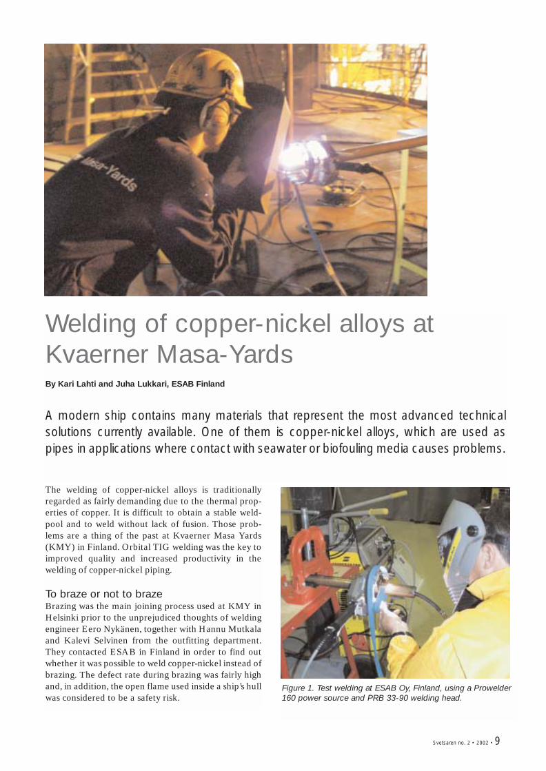
The welding of copper-nickel alloys is traditionallyregarded as fairly demanding due to the thermal prop-erties of copper. It is difficult to obtain a stable weld-pool and to weld without lack of fusion. Those prob-lems are a thing of the past at Kvaerner Masa Yards(KMY) in Finland. Orbital TIG welding was the key toimproved quality and increased productivity in thewelding of copper-nickel piping.
To braze or not to brazeBrazing was the main joining process used at KMY inHelsinki prior to the unprejudiced thoughts of weldingengineer Eero Nykänen, together with Hannu Mutkalaand Kalevi Selvinen from the outfitting department.They contacted ESAB in Finland in order to find outwhether it was possible to weld copper-nickel instead ofbrazing. The defect rate during brazing was fairly highand, in addition, the open flame used inside a ship’s hullwas considered to be a safety risk.
Figure 1. Test welding at ESAB Oy, Finland, using a Prowelder160 power source and PRB 33-90 welding head.
10 • Svetsaren no. 2 • 2002
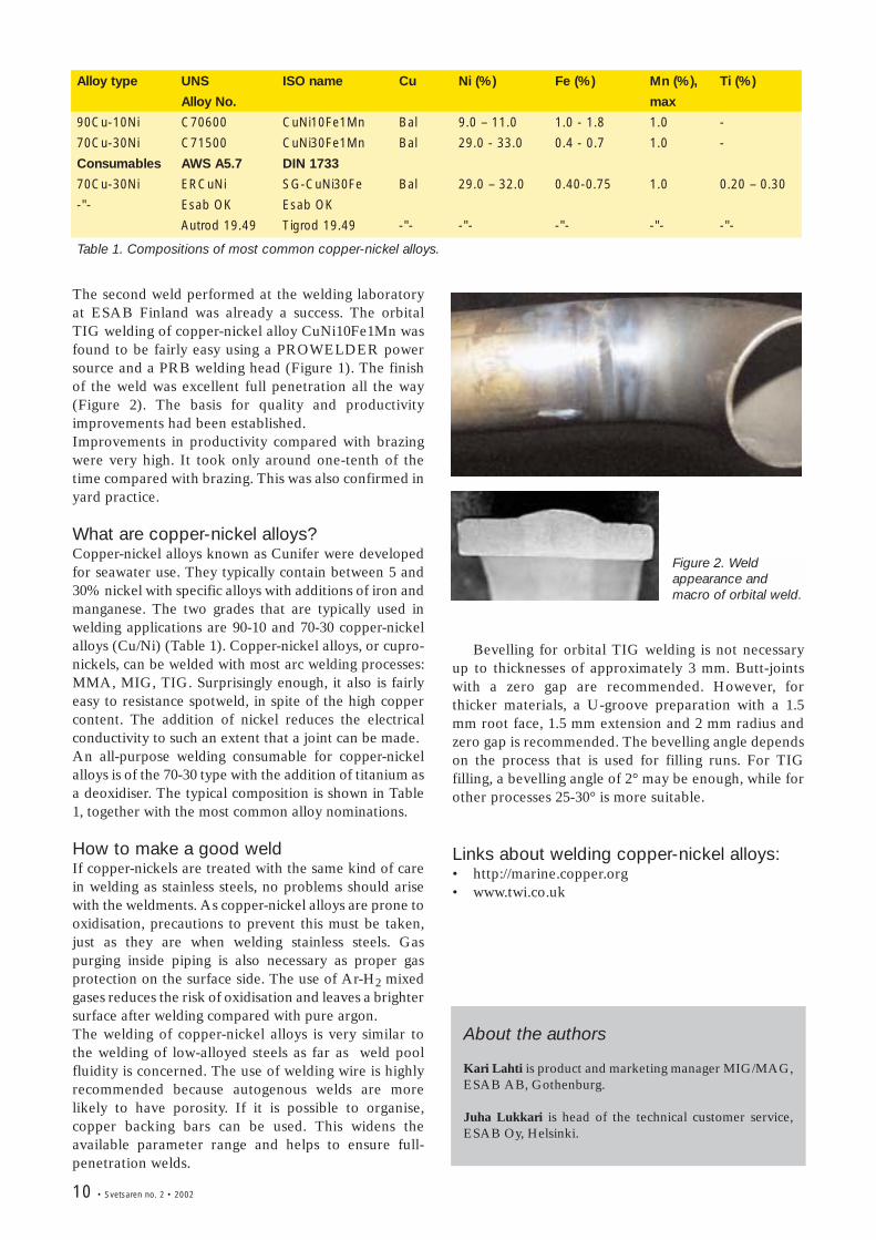
Alloy type UNS ISO name Cu Ni (%) Fe (%) Mn (%), Ti (%)
Alloy No. max
90Cu-10Ni C70600 CuNi10Fe1Mn Bal 9.0 – 11.0 1.0 - 1.8 1.0 -
70Cu-30Ni C71500 CuNi30Fe1Mn Bal 29.0 - 33.0 0.4 - 0.7 1.0 -
Consumables AWS A5.7 DIN 1733
70Cu-30Ni ERCuNi SG-CuNi30Fe Bal 29.0 – 32.0 0.40-0.75 1.0 0.20 – 0.30
-"- Esab OK Esab OK
Autrod 19.49 Tigrod 19.49 -"- -"- -"- -"- -"-
Table 1. Compositions of most common copper-nickel alloys.
Figure 2. Weldappearance andmacro of orbital weld.
The second weld performed at the welding laboratoryat ESAB Finland was already a success. The orbitalTIG welding of copper-nickel alloy CuNi10Fe1Mn wasfound to be fairly easy using a PROWELDER powersource and a PRB welding head (Figure 1). The finishof the weld was excellent full penetration all the way(Figure 2). The basis for quality and productivityimprovements had been established.Improvements in productivity compared with brazingwere very high. It took only around one-tenth of thetime compared with brazing. This was also confirmed inyard practice.
What are copper-nickel alloys?Copper-nickel alloys known as Cunifer were developedfor seawater use. They typically contain between 5 and30% nickel with specific alloys with additions of iron andmanganese. The two grades that are typically used inwelding applications are 90-10 and 70-30 copper-nickelalloys (Cu/Ni) (Table 1). Copper-nickel alloys, or cupro-nickels, can be welded with most arc welding processes:MMA, MIG, TIG. Surprisingly enough, it also is fairlyeasy to resistance spotweld, in spite of the high coppercontent. The addition of nickel reduces the electricalconductivity to such an extent that a joint can be made.An all-purpose welding consumable for copper-nickelalloys is of the 70-30 type with the addition of titanium asa deoxidiser. The typical composition is shown in Table1, together with the most common alloy nominations.
How to make a good weldIf copper-nickels are treated with the same kind of carein welding as stainless steels, no problems should arisewith the weldments. As copper-nickel alloys are prone tooxidisation, precautions to prevent this must be taken,just as they are when welding stainless steels. Gaspurging inside piping is also necessary as proper gasprotection on the surface side. The use of Ar-H2 mixedgases reduces the risk of oxidisation and leaves a brightersurface after welding compared with pure argon.The welding of copper-nickel alloys is very similar tothe welding of low-alloyed steels as far as weld poolfluidity is concerned. The use of welding wire is highlyrecommended because autogenous welds are morelikely to have porosity. If it is possible to organise,copper backing bars can be used. This widens theavailable parameter range and helps to ensure full-penetration welds.
Bevelling for orbital TIG welding is not necessaryup to thicknesses of approximately 3 mm. Butt-jointswith a zero gap are recommended. However, forthicker materials, a U-groove preparation with a 1.5mm root face, 1.5 mm extension and 2 mm radius andzero gap is recommended. The bevelling angle dependson the process that is used for filling runs. For TIGfilling, a bevelling angle of 2° may be enough, while forother processes 25-30° is more suitable.
Links about welding copper-nickel alloys:• http://marine.copper.org• www.twi.co.uk
About the authors
Kari Lahti is product and marketing manager MIG/MAG,ESAB AB, Gothenburg.
Juha Lukkari is head of the technical customer service,ESAB Oy, Helsinki.
Svetsaren no. 2 • 2002 • 11
Friction Stir Welding – progress in R&Dand new applications By Lars Göran Eriksson and Rolf Larsson, ESAB AB, Welding Automation, Laxå
In spite of its very recent introduction into industry, Friction Stir Welding is alreadyfrequently used in production. This article presents some recent results from thecontinuous research work that is in progress on the process, a new machine seriesthat is going to be introduced and an extremely fascinating new application in thewelding of thick copper.
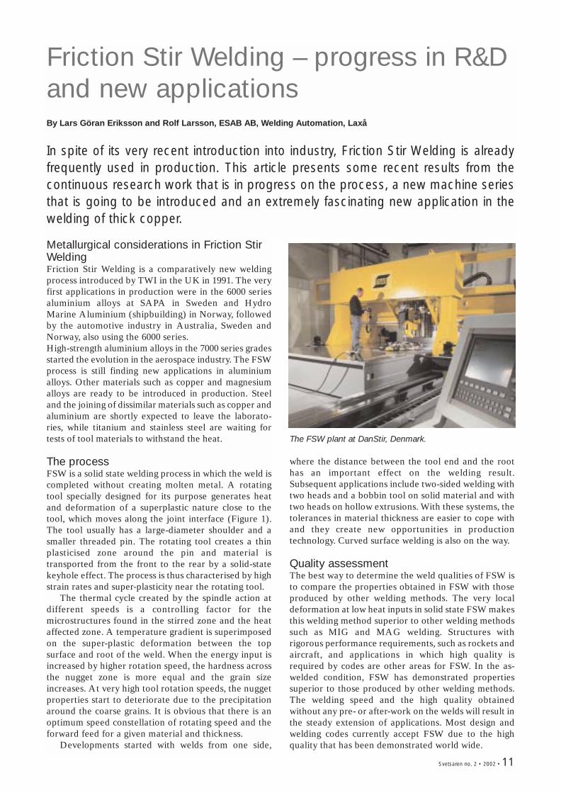
Metallurgical considerations in Friction StirWeldingFriction Stir Welding is a comparatively new weldingprocess introduced by TWI in the UK in 1991. The veryfirst applications in production were in the 6000 seriesaluminium alloys at SAPA in Sweden and HydroMarine Aluminium (shipbuilding) in Norway, followedby the automotive industry in Australia, Sweden andNorway, also using the 6000 series.High-strength aluminium alloys in the 7000 series gradesstarted the evolution in the aerospace industry. The FSWprocess is still finding new applications in aluminiumalloys. Other materials such as copper and magnesiumalloys are ready to be introduced in production. Steeland the joining of dissimilar materials such as copper andaluminium are shortly expected to leave the laborato-ries, while titanium and stainless steel are waiting fortests of tool materials to withstand the heat.
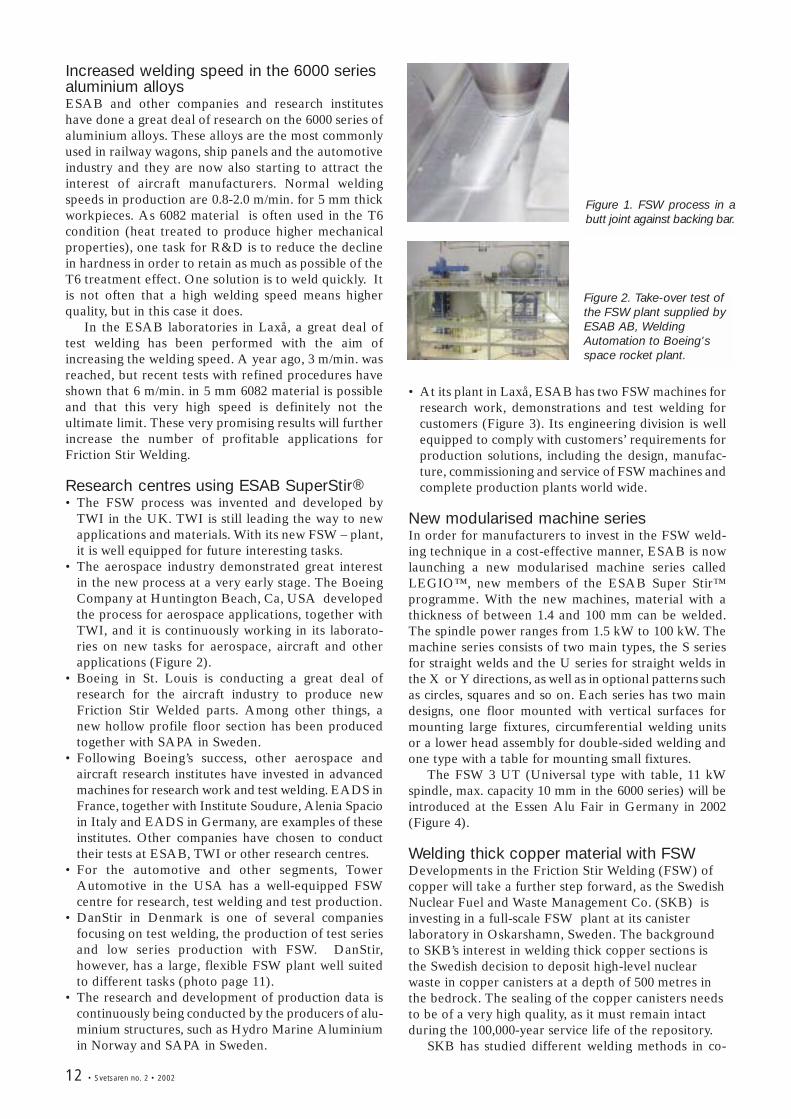
The processFSW is a solid state welding process in which the weld iscompleted without creating molten metal. A rotatingtool specially designed for its purpose generates heatand deformation of a superplastic nature close to thetool, which moves along the joint interface (Figure 1).The tool usually has a large-diameter shoulder and asmaller threaded pin. The rotating tool creates a thinplasticised zone around the pin and material istransported from the front to the rear by a solid-statekeyhole effect. The process is thus characterised by highstrain rates and super-plasticity near the rotating tool.
The thermal cycle created by the spindle action atdifferent speeds is a controlling factor for themicrostructures found in the stirred zone and the heataffected zone. A temperature gradient is superimposedon the super-plastic deformation between the topsurface and root of the weld. When the energy input isincreased by higher rotation speed, the hardness acrossthe nugget zone is more equal and the grain sizeincreases. At very high tool rotation speeds, the nuggetproperties start to deteriorate due to the precipitationaround the coarse grains. It is obvious that there is anoptimum speed constellation of rotating speed and theforward feed for a given material and thickness.
Developments started with welds from one side,
where the distance between the tool end and the roothas an important effect on the welding result.Subsequent applications include two-sided welding withtwo heads and a bobbin tool on solid material and withtwo heads on hollow extrusions. With these systems, thetolerances in material thickness are easier to cope withand they create new opportunities in productiontechnology. Curved surface welding is also on the way.
Quality assessmentThe best way to determine the weld qualities of FSW isto compare the properties obtained in FSW with thoseproduced by other welding methods. The very localdeformation at low heat inputs in solid state FSW makesthis welding method superior to other welding methodssuch as MIG and MAG welding. Structures withrigorous performance requirements, such as rockets andaircraft, and applications in which high quality isrequired by codes are other areas for FSW. In the as-welded condition, FSW has demonstrated propertiessuperior to those produced by other welding methods.The welding speed and the high quality obtainedwithout any pre- or after-work on the welds will result inthe steady extension of applications. Most design andwelding codes currently accept FSW due to the highquality that has been demonstrated world wide.
The FSW plant at DanStir, Denmark.
12 • Svetsaren no. 2 • 2002
Increased welding speed in the 6000 seriesaluminium alloysESAB and other companies and research instituteshave done a great deal of research on the 6000 series ofaluminium alloys. These alloys are the most commonlyused in railway wagons, ship panels and the automotiveindustry and they are now also starting to attract theinterest of aircraft manufacturers. Normal weldingspeeds in production are 0.8-2.0 m/min. for 5 mm thickworkpieces. As 6082 material is often used in the T6condition (heat treated to produce higher mechanicalproperties), one task for R&D is to reduce the declinein hardness in order to retain as much as possible of theT6 treatment effect. One solution is to weld quickly. Itis not often that a high welding speed means higherquality, but in this case it does.
In the ESAB laboratories in Laxå, a great deal oftest welding has been performed with the aim ofincreasing the welding speed. A year ago, 3 m/min. wasreached, but recent tests with refined procedures haveshown that 6 m/min. in 5 mm 6082 material is possibleand that this very high speed is definitely not theultimate limit. These very promising results will furtherincrease the number of profitable applications forFriction Stir Welding.
Research centres using ESAB SuperStir® • The FSW process was invented and developed by
TWI in the UK. TWI is still leading the way to newapplications and materials. With its new FSW – plant,it is well equipped for future interesting tasks.
• The aerospace industry demonstrated great interestin the new process at a very early stage. The BoeingCompany at Huntington Beach, Ca, USA developedthe process for aerospace applications, together withTWI, and it is continuously working in its laborato-ries on new tasks for aerospace, aircraft and otherapplications (Figure 2).
• Boeing in St. Louis is conducting a great deal ofresearch for the aircraft industry to produce newFriction Stir Welded parts. Among other things, anew hollow profile floor section has been producedtogether with SAPA in Sweden.
• Following Boeing’s success, other aerospace andaircraft research institutes have invested in advancedmachines for research work and test welding. EADS inFrance, together with Institute Soudure, Alenia Spacioin Italy and EADS in Germany, are examples of theseinstitutes. Other companies have chosen to conducttheir tests at ESAB, TWI or other research centres.
• For the automotive and other segments, TowerAutomotive in the USA has a well-equipped FSWcentre for research, test welding and test production.
• DanStir in Denmark is one of several companiesfocusing on test welding, the production of test seriesand low series production with FSW. DanStir,however, has a large, flexible FSW plant well suitedto different tasks (photo page 11).
• The research and development of production data iscontinuously being conducted by the producers of alu-minium structures, such as Hydro Marine Aluminiumin Norway and SAPA in Sweden.
Figure 1. FSW process in abutt joint against backing bar.
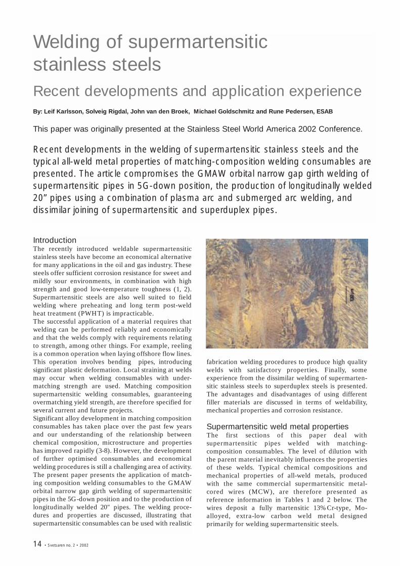
• At its plant in Laxå, ESAB has two FSW machines forresearch work, demonstrations and test welding forcustomers (Figure 3). Its engineering division is wellequipped to comply with customers’ requirements forproduction solutions, including the design, manufac-ture, commissioning and service of FSW machines andcomplete production plants world wide.
New modularised machine seriesIn order for manufacturers to invest in the FSW weld-ing technique in a cost-effective manner, ESAB is nowlaunching a new modularised machine series calledLEGIO™, new members of the ESAB Super Stir™programme. With the new machines, material with athickness of between 1.4 and 100 mm can be welded.The spindle power ranges from 1.5 kW to 100 kW. Themachine series consists of two main types, the S seriesfor straight welds and the U series for straight welds inthe X or Y directions, as well as in optional patterns suchas circles, squares and so on. Each series has two maindesigns, one floor mounted with vertical surfaces formounting large fixtures, circumferential welding unitsor a lower head assembly for double-sided welding andone type with a table for mounting small fixtures.
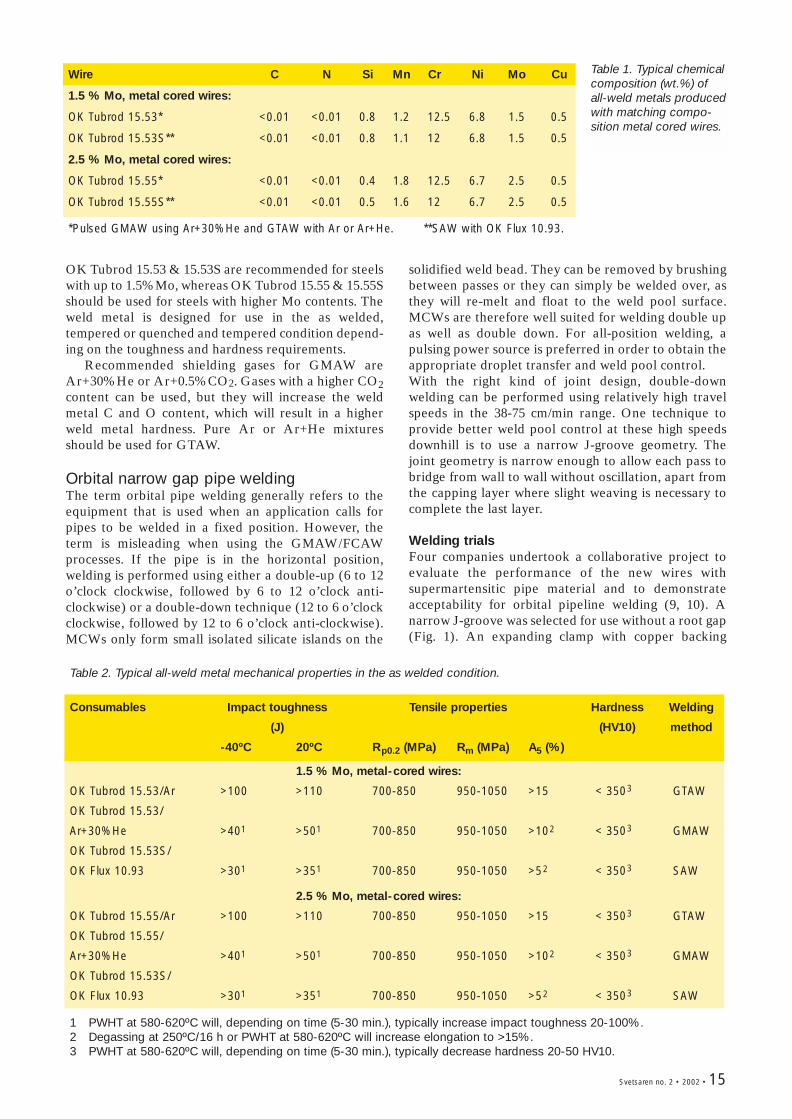
The FSW 3 UT (Universal type with table, 11 kWspindle, max. capacity 10 mm in the 6000 series) will beintroduced at the Essen Alu Fair in Germany in 2002(Figure 4).
Welding thick copper material with FSWDevelopments in the Friction Stir Welding (FSW) ofcopper will take a further step forward, as the SwedishNuclear Fuel and Waste Management Co. (SKB) isinvesting in a full-scale FSW plant at its canisterlaboratory in Oskarshamn, Sweden. The backgroundto SKB’s interest in welding thick copper sections isthe Swedish decision to deposit high-level nuclearwaste in copper canisters at a depth of 500 metres inthe bedrock. The sealing of the copper canisters needsto be of a very high quality, as it must remain intactduring the 100,000-year service life of the repository.
SKB has studied different welding methods in co-
Figure 2. Take-over test ofthe FSW plant supplied byESAB AB, WeldingAutomation to Boeing'sspace rocket plant.
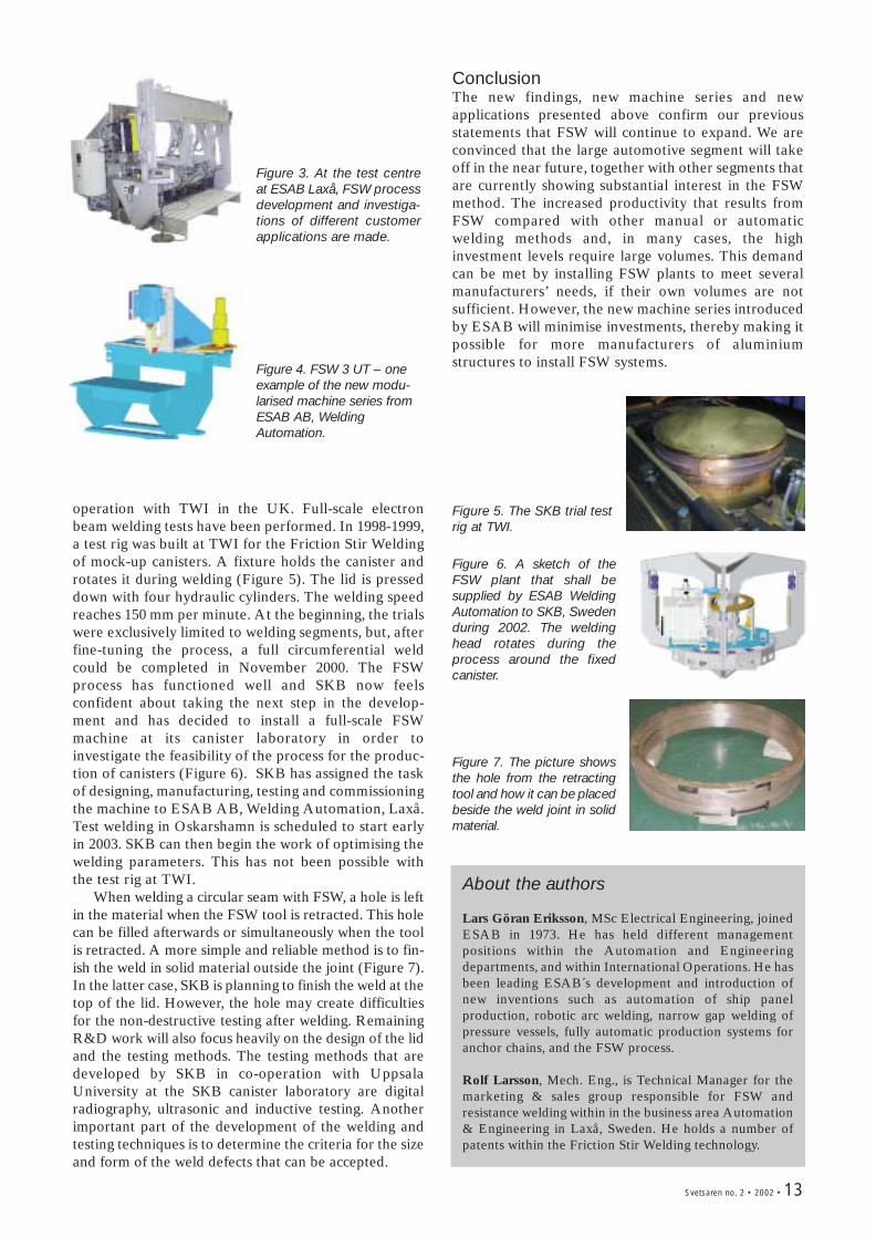
Figure 3. At the test centreat ESAB Laxå, FSW processdevelopment and investiga-tions of different customerapplications are made.
Svetsaren no. 2 • 2002 • 13
Figure 4. FSW 3 UT – oneexample of the new modu-larised machine series fromESAB AB, WeldingAutomation.
operation with TWI in the UK. Full-scale electronbeam welding tests have been performed. In 1998-1999,a test rig was built at TWI for the Friction Stir Weldingof mock-up canisters. A fixture holds the canister androtates it during welding (Figure 5). The lid is presseddown with four hydraulic cylinders. The welding speedreaches 150 mm per minute. At the beginning, the trialswere exclusively limited to welding segments, but, afterfine-tuning the process, a full circumferential weldcould be completed in November 2000. The FSWprocess has functioned well and SKB now feelsconfident about taking the next step in the develop-ment and has decided to install a full-scale FSWmachine at its canister laboratory in order toinvestigate the feasibility of the process for the produc-tion of canisters (Figure 6). SKB has assigned the taskof designing, manufacturing, testing and commissioningthe machine to ESAB AB, Welding Automation, Laxå.Test welding in Oskarshamn is scheduled to start earlyin 2003. SKB can then begin the work of optimising thewelding parameters. This has not been possible withthe test rig at TWI.
When welding a circular seam with FSW, a hole is leftin the material when the FSW tool is retracted. This holecan be filled afterwards or simultaneously when the toolis retracted. A more simple and reliable method is to fin-ish the weld in solid material outside the joint (Figure 7).In the latter case, SKB is planning to finish the weld at thetop of the lid. However, the hole may create difficultiesfor the non-destructive testing after welding. RemainingR&D work will also focus heavily on the design of the lidand the testing methods. The testing methods that aredeveloped by SKB in co-operation with UppsalaUniversity at the SKB canister laboratory are digitalradiography, ultrasonic and inductive testing. Anotherimportant part of the development of the welding andtesting techniques is to determine the criteria for the sizeand form of the weld defects that can be accepted.
ConclusionThe new findings, new machine series and newapplications presented above confirm our previousstatements that FSW will continue to expand. We areconvinced that the large automotive segment will takeoff in the near future, together with other segments thatare currently showing substantial interest in the FSWmethod. The increased productivity that results fromFSW compared with other manual or automaticwelding methods and, in many cases, the highinvestment levels require large volumes. This demandcan be met by installing FSW plants to meet severalmanufacturers’ needs, if their own volumes are notsufficient. However, the new machine series introducedby ESAB will minimise investments, thereby making itpossible for more manufacturers of aluminiumstructures to install FSW systems.
Figure 5. The SKB trial testrig at TWI.
Figure 6. A sketch of theFSW plant that shall besupplied by ESAB WeldingAutomation to SKB, Swedenduring 2002. The weldinghead rotates during theprocess around the fixedcanister.
Figure 7. The picture showsthe hole from the retractingtool and how it can be placedbeside the weld joint in solidmaterial.
About the authors
Lars Göran Eriksson, MSc Electrical Engineering, joinedESAB in 1973. He has held different managementpositions within the Automation and Engineeringdepartments, and within International Operations. He hasbeen leading ESAB´s development and introduction ofnew inventions such as automation of ship panelproduction, robotic arc welding, narrow gap welding ofpressure vessels, fully automatic production systems foranchor chains, and the FSW process.
Rolf Larsson, Mech. Eng., is Technical Manager for themarketing & sales group responsible for FSW andresistance welding within in the business area Automation& Engineering in Laxå, Sweden. He holds a number ofpatents within the Friction Stir Welding technology.
14 • Svetsaren no. 2 • 2002
Welding of supermartensitic stainless steels Recent developments and application experienceBy: Leif Karlsson, Solveig Rigdal, John van den Broek, Michael Goldschmitz and Rune Pedersen, ESAB
This paper was originally presented at the Stainless Steel World America 2002 Conference.
Recent developments in the welding of supermartensitic stainless steels and thetypical all-weld metal properties of matching-composition welding consumables arepresented. The article compromises the GMAW orbital narrow gap girth welding ofsupermartensitic pipes in 5G-down position, the production of longitudinally welded20” pipes using a combination of plasma arc and submerged arc welding, anddissimilar joining of supermartensitic and superduplex pipes.
IntroductionThe recently introduced weldable supermartensiticstainless steels have become an economical alternativefor many applications in the oil and gas industry. Thesesteels offer sufficient corrosion resistance for sweet andmildly sour environments, in combination with highstrength and good low-temperature toughness (1, 2).Supermartensitic steels are also well suited to fieldwelding where preheating and long term post-weldheat treatment (PWHT) is impracticable. The successful application of a material requires thatwelding can be performed reliably and economicallyand that the welds comply with requirements relatingto strength, among other things. For example, reelingis a common operation when laying offshore flow lines.This operation involves bending pipes, introducingsignificant plastic deformation. Local straining at weldsmay occur when welding consumables with under-matching strength are used. Matching compositionsupermartensitic welding consumables, guaranteeingovermatching yield strength, are therefore specified forseveral current and future projects. Significant alloy development in matching compositionconsumables has taken place over the past few yearsand our understanding of the relationship betweenchemical composition, microstructure and propertieshas improved rapidly (3-8). However, the developmentof further optimised consumables and economicalwelding procedures is still a challenging area of activity. The present paper presents the application of match-ing composition welding consumables to the GMAWorbital narrow gap girth welding of supermartensiticpipes in the 5G-down position and to the production oflongitudinally welded 20" pipes. The welding proce-dures and properties are discussed, illustrating thatsupermartensitic consumables can be used with realistic
fabrication welding procedures to produce high qualitywelds with satisfactory properties. Finally, someexperience from the dissimilar welding of supermarten-sitic stainless steels to superduplex steels is presented.The advantages and disadvantages of using differentfiller materials are discussed in terms of weldability,mechanical properties and corrosion resistance.
Supermartensitic weld metal properties The first sections of this paper deal withsupermartensitic pipes welded with matching-composition consumables. The level of dilution withthe parent material inevitably influences the propertiesof these welds. Typical chemical compositions andmechanical properties of all-weld metals, producedwith the same commercial supermartensitic metal-cored wires (MCW), are therefore presented asreference information in Tables 1 and 2 below. Thewires deposit a fully martensitic 13%Cr-type, Mo-alloyed, extra-low carbon weld metal designedprimarily for welding supermartensitic steels.
Wire C N Si Mn Cr Ni Mo Cu
1.5 % Mo, metal cored wires:
OK Tubrod 15.53* <0.01 <0.01 0.8 1.2 12.5 6.8 1.5 0.5
OK Tubrod 15.53S** <0.01 <0.01 0.8 1.1 12 6.8 1.5 0.5
2.5 % Mo, metal cored wires:
OK Tubrod 15.55* <0.01 <0.01 0.4 1.8 12.5 6.7 2.5 0.5
OK Tubrod 15.55S** <0.01 <0.01 0.5 1.6 12 6.7 2.5 0.5
*Pulsed GMAW using Ar+30%He and GTAW with Ar or Ar+He. **SAW with OK Flux 10.93.
Table 1. Typical chemicalcomposition (wt.%) ofall-weld metals producedwith matching compo-sition metal cored wires.
Table 2. Typical all-weld metal mechanical properties in the as welded condition.
Consumables Impact toughness Tensile properties Hardness Welding
(J) (HV10) method
-40ºC 20ºC Rp0.2 (MPa) Rm (MPa) A5 (%)
1.5 % Mo, metal-cored wires:
OK Tubrod 15.53/Ar >100 >110 700-850 950-1050 >15 < 3503 GTAW
OK Tubrod 15.53/
Ar+30%He >401 >501 700-850 950-1050 >102 < 3503 GMAW
OK Tubrod 15.53S/
OK Flux 10.93 >301 >351 700-850 950-1050 >52 < 3503 SAW
2.5 % Mo, metal-cored wires:
OK Tubrod 15.55/Ar >100 >110 700-850 950-1050 >15 < 3503 GTAW
OK Tubrod 15.55/
Ar+30%He >401 >501 700-850 950-1050 >102 < 3503 GMAW
OK Tubrod 15.53S/
OK Flux 10.93 >301 >351 700-850 950-1050 >52 < 3503 SAW
1 PWHT at 580-620ºC will, depending on time (5-30 min.), typically increase impact toughness 20-100%.2 Degassing at 250ºC/16 h or PWHT at 580-620ºC will increase elongation to >15%.3 PWHT at 580-620ºC will, depending on time (5-30 min.), typically decrease hardness 20-50 HV10.
OK Tubrod 15.53 & 15.53S are recommended for steelswith up to 1.5%Mo, whereas OK Tubrod 15.55 & 15.55Sshould be used for steels with higher Mo contents. Theweld metal is designed for use in the as welded,tempered or quenched and tempered condition depend-ing on the toughness and hardness requirements.
Recommended shielding gases for GMAW areAr+30%He or Ar+0.5%CO2. Gases with a higher CO2content can be used, but they will increase the weldmetal C and O content, which will result in a higherweld metal hardness. Pure Ar or Ar+He mixturesshould be used for GTAW.
Orbital narrow gap pipe weldingThe term orbital pipe welding generally refers to theequipment that is used when an application calls forpipes to be welded in a fixed position. However, theterm is misleading when using the GMAW/FCAWprocesses. If the pipe is in the horizontal position,welding is performed using either a double-up (6 to 12o’clock clockwise, followed by 6 to 12 o’clock anti-clockwise) or a double-down technique (12 to 6 o’clockclockwise, followed by 12 to 6 o’clock anti-clockwise).MCWs only form small isolated silicate islands on the
solidified weld bead. They can be removed by brushingbetween passes or they can simply be welded over, asthey will re-melt and float to the weld pool surface.MCWs are therefore well suited for welding double upas well as double down. For all-position welding, apulsing power source is preferred in order to obtain theappropriate droplet transfer and weld pool control.With the right kind of joint design, double-downwelding can be performed using relatively high travelspeeds in the 38-75 cm/min range. One technique toprovide better weld pool control at these high speedsdownhill is to use a narrow J-groove geometry. Thejoint geometry is narrow enough to allow each pass tobridge from wall to wall without oscillation, apart fromthe capping layer where slight weaving is necessary tocomplete the last layer.
Welding trialsFour companies undertook a collaborative project toevaluate the performance of the new wires withsupermartensitic pipe material and to demonstrateacceptability for orbital pipeline welding (9, 10). Anarrow J-groove was selected for use without a root gap(Fig. 1). An expanding clamp with copper backing
Svetsaren no. 2 • 2002 • 15
16 • Svetsaren no. 2 • 2002
Pass Position Amperage Arc Voltage Wire feed Welding speed
(A) (V) (m/min) (cm/min)
Root 12-4 o’clock 210 18.8 9.3 70
Fill 2,3,4 12-4 o’clock 215 21.5 9.0 50
Cap* 12-6 o’clock 140 18 3.0 18
Root 4-6 o’clock 178 17.5 6.0 22
Fill 2,3 4-6 o’clock 175 17.5 6.0 22
Cap* 12-6 o’clock 140 18 3.0 18
*Slight weaving
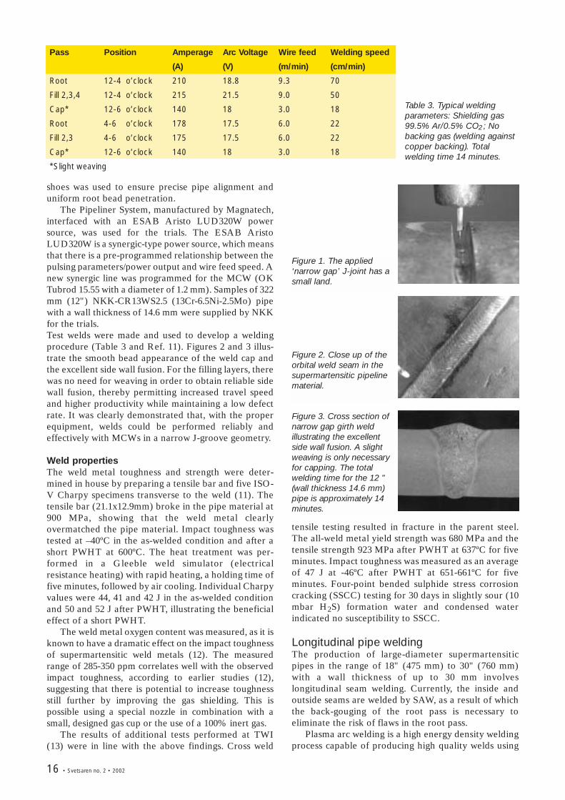
Figure 1. The applied‘narrow gap’ J-joint has asmall land.
Figure 2. Close up of theorbital weld seam in thesupermartensitic pipelinematerial.
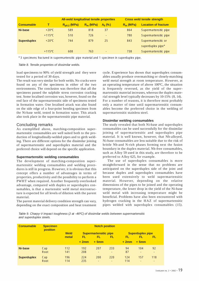
Figure 3. Cross section ofnarrow gap girth weldillustrating the excellentside wall fusion. A slightweaving is only necessaryfor capping. The totalwelding time for the 12 "(wall thickness 14.6 mm)pipe is approximately 14minutes.
shoes was used to ensure precise pipe alignment anduniform root bead penetration.
The Pipeliner System, manufactured by Magnatech,interfaced with an ESAB Aristo LUD320W powersource, was used for the trials. The ESAB AristoLUD320W is a synergic-type power source, which meansthat there is a pre-programmed relationship between thepulsing parameters/power output and wire feed speed. Anew synergic line was programmed for the MCW (OKTubrod 15.55 with a diameter of 1.2 mm). Samples of 322mm (12") NKK-CR13WS2.5 (13Cr-6.5Ni-2.5Mo) pipewith a wall thickness of 14.6 mm were supplied by NKKfor the trials. Test welds were made and used to develop a weldingprocedure (Table 3 and Ref. 11). Figures 2 and 3 illus-trate the smooth bead appearance of the weld cap andthe excellent side wall fusion. For the filling layers, therewas no need for weaving in order to obtain reliable sidewall fusion, thereby permitting increased travel speedand higher productivity while maintaining a low defectrate. It was clearly demonstrated that, with the properequipment, welds could be performed reliably andeffectively with MCWs in a narrow J-groove geometry.
Weld propertiesThe weld metal toughness and strength were deter-mined in house by preparing a tensile bar and five ISO-V Charpy specimens transverse to the weld (11). Thetensile bar (21.1x12.9mm) broke in the pipe material at900 MPa, showing that the weld metal clearlyovermatched the pipe material. Impact toughness wastested at –40ºC in the as-welded condition and after ashort PWHT at 600ºC. The heat treatment was per-formed in a Gleeble weld simulator (electricalresistance heating) with rapid heating, a holding time offive minutes, followed by air cooling. Individual Charpyvalues were 44, 41 and 42 J in the as-welded conditionand 50 and 52 J after PWHT, illustrating the beneficialeffect of a short PWHT.
The weld metal oxygen content was measured, as it isknown to have a dramatic effect on the impact toughnessof supermartensitic weld metals (12). The measuredrange of 285-350 ppm correlates well with the observedimpact toughness, according to earlier studies (12),suggesting that there is potential to increase toughnessstill further by improving the gas shielding. This ispossible using a special nozzle in combination with asmall, designed gas cup or the use of a 100% inert gas.
The results of additional tests performed at TWI(13) were in line with the above findings. Cross weld
tensile testing resulted in fracture in the parent steel.The all-weld metal yield strength was 680 MPa and thetensile strength 923 MPa after PWHT at 637ºC for fiveminutes. Impact toughness was measured as an averageof 47 J at -46ºC after PWHT at 651-661ºC for fiveminutes. Four-point bended sulphide stress corrosioncracking (SSCC) testing for 30 days in slightly sour (10mbar H2S) formation water and condensed waterindicated no susceptibility to SSCC.
Longitudinal pipe weldingThe production of large-diameter supermartensiticpipes in the range of 18" (475 mm) to 30" (760 mm)with a wall thickness of up to 30 mm involveslongitudinal seam welding. Currently, the inside andoutside seams are welded by SAW, as a result of whichthe back-gouging of the root pass is necessary toeliminate the risk of flaws in the root pass.
Plasma arc welding is a high energy density weldingprocess capable of producing high quality welds using
Table 3. Typical weldingparameters: Shielding gas99.5% Ar/0.5% CO2 ; Nobacking gas (welding againstcopper backing). Totalwelding time 14 minutes.
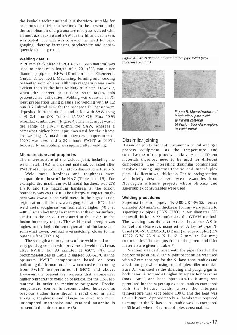
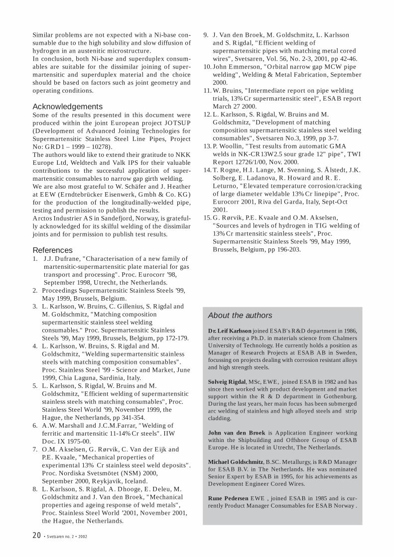
Figure 4. Cross section of longitudinal pipe weld (wallthickness 20 mm).
Figure 5. Microstructure oflongitudinal pipe weld.a) Parent material.b) Fusion boundary region.c) Weld metal.
the keyhole technique and it is therefore suitable forroot runs on thick pipe sections. In the present study,the combination of a plasma arc root pass welded withan inert gas backing and SAW for the fill and cap layerswas tested. The aim was to avoid the need for backgouging, thereby increasing productivity and conse-quently reducing costs.
Welding detailsA 20 mm thick plate of 12Cr 4.5Ni 1.5Mo material wasused to produce a length of a 20" (508 mm outerdiameter) pipe at EEW (Erndtebrücker Eisenwerk,GmbH & Co. KG). Machining, forming and weldingpresented no problems, although magnetism was moreevident than in the butt welding of plates. However,when the correct precautions were taken, thispresented no difficulties. Welding was done in an X-joint preparation using plasma arc welding with Ø 1.2mm OK Tubrod 15.53 for the root pass. Fill passes weredeposited from the outside and inside with SAW usinga Ø 2.4 mm OK Tubrod 15.53S/ OK Flux 10.93wire/flux combination (Figure 4). The heat input was inthe range of 1.0-1.7 kJ/mm for SAW, whereas asomewhat higher heat input was used for the plasmaarc welding. A maximum interpass temperature of150ºC was used and a 30 minute PWHT at 630ºC,followed by air cooling, was applied after welding.
Microstructure and propertiesThe microstructure of the welded joint, including theweld metal, HAZ and parent material, consisted afterPWHT of tempered martensite as illustrated in Figure 5.
Weld metal hardness and toughness werecomparable to those of the HAZ (Tables 4 and 5). Forexample, the maximum weld metal hardness was 278HV10 and the maximum hardness at the fusionboundary was 280 HV10. The Charpy-V impact tough-ness was lowest in the weld metal in the high-dilutionregion at mid-thickness, averaging 62 J at –40ºC. Theweld metal toughness was somewhat higher (70 J at–40ºC) when locating the specimen at the outer surface,similar to the 77-79 J measured in the HAZ in thefusion boundary region. The weld metal strength washighest in the high-dilution region at mid-thickness andsomewhat lower, but still overmatching, closer to theouter surface (Table 6).
The strength and toughness of the weld metal are invery good agreement with previous all-weld metal testsafter PWHT for 30 minutes at 620ºC (8). Therecommendations in Table 2 suggest 580-620ºC as theoptimum PWHT temperatures based on testsindicating the formation of new martensite on coolingfrom PWHT temperatures of 640ºC and above.However, the present test suggests that a somewhathigher temperature could be beneficial for the 1.5%Momaterial in order to maximise toughness. Precisetemperature control is recommended, however, asprevious studies have shown a rapid drop in yieldstrength, toughness and elongation once too muchuntempered martensite and retained austenite ispresent in the microstructure (8).
Dissimilar joiningDissimilar joints are not uncommon in oil and gasprocess equipment, as the temperature andcorrosiveness of the process media vary and differentmaterials therefore need to be used for differentcomponents. One interesting dissimilar combinationinvolves joining supermartensitic and superduplexpipes of different wall thickness. The following sectionwill briefly describe two recent examples fromNorwegian offshore projects where Ni-base andsuperduplex consumables were used.
Welding proceduresSupermartensitic pipes (K-X80-CR13WS2, outerdiameter 324 mm/wall thickness 16 mm) were joined tosuperduplex pipes (UNS 32760, outer diameter 335mm/wall thickness 22 mm) using the GTAW method.The welding was done at Arctos Industrier AS inSandefjord (Norway), using either Alloy 59 type Nibased (SG-Ni Cr23Mo16, Ø 2 mm) or superduplex (EN12072 G/W 25 9 4 N L, Ø 2 mm an 2.4 mm)consumables. The compositions of the parent and fillermaterials are given in Table 7.
Welding was performed with the pipes fixed in thehorizontal position. A 60º V-joint preparation was usedwith a 2 mm root gap for the Ni-base consumables anda 3-4 mm gap when using superduplex filler material.Pure Ar was used as the shielding and purging gas inboth cases. A somewhat higher interpass temperature(max 150ºC) and heat input (0.9-1.2 kJ/mm) waspermitted for the superduplex consumables comparedwith the Ni-base welds, where the interpasstemperature was kept below 100ºC and the heat was0.9-1.1 kJ/mm. Approximately 45 beads were requiredto complete the Ni-base consumable weld as comparedto 35 beads when using superduplex consumables.
Svetsaren no. 2 • 2002 • 17

18 • Svetsaren no. 2 • 2002
Table 7. Chemical composition (wt.%) of pipe materials and filler wires used for dissimilar joints.
C N Si Mn Cr Ni Mo W Cu Fe
Supermartensitic pipe 0.015 0.012 0.2 0.17 12.3 5.9 2.2 - 0.05 rest
Superduplex pipe 0.017 0.23 0.36 0.68 25.6 7.4 3.5 0.6 0.6 rest
OK Tigrod 19.81 0.003 - 0.05 0.2 22.8 rest 15.4 - - 0.4
OK Tigrod 16.88* <0.003 0.25 0.5 0.5 25.0 9.5 4.0 - - rest
* typical all-weld metal analysis
Position Hardness (HV10)Min Max
Parent material 233 263Fusion line 242 280Weld metal 264 278
Table 4. Hardness of longitudinally welded pipe, postweld heat treated at 630ºC for 30 minutes.
Specimen Longitudinal tensile propertiesposition
Rp0.2 (MPa) Rm (MPa) A5 (%)
Outside 880 974 15Mid thickness 954 1001 16
Table 6. Weld metal tensile properties in longitudinalweld after a 630ºC/ 30 min PWHT.
Specimen Notch positionposition Weld FL FL FL Parent
metal +2mm +5mm materialOutside 70 77 79 77 104Mid thickness 62 87 70 123 102
Table 5. Charpy-V impact toughness (J at -40ºC) oflongitudinally welded pipe, post weld heat treated at630ºC for 30 minutes.
Testing and inspectionThe welds were subjected to an extensive testprogramme, including non-destructive testing,microscopy, transverse and longitudinal testing at roomtemperature and at 115ºC, Charpy-V testing at -46ºC,bend testing, hardness measurements and sulphidestress corrosion cracking (SSCC) testing. Radiographic inspection and sectioning of the weldsrevealed no defects and the microstructure was judgedto be sound. One comment can, however, be made;microscopy revealed some precipitation of nitrides andsecondary austenite in the HAZ of the superduplexpipe in the Ni-base weld. The superduplex weld had aferrite content ranging from 30.4% in the root to 51.5%in the cap and no comments were made on the HAZmicrostructure.
Mechanical testingThe yield and tensile strength of the Ni-base weld waslower than that of the superduplex weld at both roomand elevated temperature (Table 8). However, fracturein cross-weld testing took place in the parent material,
regardless of the consumable and test temperature. Itshould be noted that the strength of the superduplexweld decreased significantly more with increasingtemperature than that of the Ni-base weld. Forexample, the yield decreased by 136 MPa for thesuperduplex weld and by 79 MPa for the Ni-base weldwhen going from 20ºC to 115ºC.
Both welds passed the 180º face and root bendingtests (mandrel 5xT for Ni based and 4xT forsuperduplex). Hardness surveys across the welds 1.5mm below the top and root surfaces revealed verysimilar behaviour for the two welds. The highesthardness was found in the HAZ in the supermartensiticpipe (up to 380 HV10) and the weld metal hardness washigher in the root than in the cap. Ni-base weld metalhardness averaged 235 HV10 in the cap region and 314HV10 in the root, whereas the corresponding hardnesswas 281 HV10 and 319 HV10 respectively for thesuperduplex weld. The hardness of the HAZ in thesuperduplex pipe was in the range of 325-345 HV10.
Charpy-V impact toughness was measured usingstandard 10x10 mm specimens extracted at variouslocations close to the cap and root surfaces (Table 9).The hardness was on a high level in both welds. Thelowest average toughness that was measured was 87 J atthe fusion line in the superduplex pipe welded with Ni-base consumables. Weld metal toughness ranged from112 J to 141 J in the Ni-base weld metal and from 114 Jto 196 J in the superduplex weld metal. Thesupermartensitic pipe material toughness was typicallyabove 200 J, whereas the superduplex pipe toughnessranged from 87 J to 157 J.
SSCC testingThe resistance to sulphide stress corrosion cracking wastested according to EFC Document No. 17 and theNorsk Hydro 33-1A-NH-R52-00002 specification.Testing was performed at room temperature incondensed water (1000 mg/l NaCl, 400 mg/l NaAc, pHadjusted to 3.6 with HCl or NaOH) and formationwater (38890 mg/l NaCl, 400 mg/l NaAc, pH adjusted to5.2 with HCl or NaOH) at 4 mbar partial pressure ofH2S. Constant load and four-point bending specimenswere prepared transverse to the weld at the pipe innersurface. Constant load specimens from the Ni-baseweld were only tested in condensed water. However,four-point bending specimens from the two welds andconstant load specimens from the superduplex weldwere tested in both condensed and formation water.The four-point bending specimens were loaded to100% of the weld metal yield strength and the constant
All-weld longitudinal tensile properties Cross weld tensile strength
Consumable T Rp0.2 (MPa) Rm (MPa) A5 (%) Rm (MPa) Location of fracture
Ni-base +20ºC 589 818 37 864 Supermartensitic pipe
+115ºC 510 726 - 780 Supermartensitic pipe
Superduplex +20ºC 744 879 25 843 Supermartensitic or
superduplex pipe*
+115ºC 608 763 - 738 Supermartensitic pipe
* 3 specimens fractured in supermartensitic pipe material and 1 specimen in superduplex pipe.
Table 8. Tensile properties of dissimilar welds.
Table 9. Charpy-V impact toughness (J at -46ºC) of dissimilar welds between supermartensitic and superduplex steels.
Consumable Specimen Notch positionposition
Weld Supermartensitic pipe Superduplex pipemetal FL FL FL FL FL FL
+ 2mm + 5mm + 2mm + 5mm
Ni-base Cap 112 192 207 233 94 104 92Root 141 208 - - 87 - -
Superduplex Cap 196 224 200 220 124 157 118Root 114 235 - - 114 - -
load specimens to 90% of yield strength and they weretested for a period of 30 days.The result was very similar for both welds. No cracks werefound on any of the specimens in either of the twoenvironments. The conclusion was therefore that all thespecimens passed the sulphide stress corrosion crackingtest. Some localised corrosion was, however, found on theend face of the supermartensitic side of specimens testedin formation water. One localised attack was also foundon the side edge of a four-point bending specimen fromthe Ni-base weld, tested in formation water. This attackalso took place in the supermartensitic pipe material.
Concluding remarksAs exemplified above, matching-composition super-martensitic consumables are well suited both to the pro-duction of longitudinally-welded pipes and to girth weld-ing. There are different options for the dissimilar joiningof supermartensitic and superduplex material and thepreferred choice will depend on the specific application.
Supermartensitic welding consumablesThe development of matching-composition super-martensitic welding consumables and welding proce-dures is still in progress. However, it is obvious that thisconcept offers a number of advantages in terms ofproperties, productivity and the possibility to perform aPWHT when required. Another frequently overlookedadvantage, compared with duplex or superduplex con-sumables, is that a martensitic weld metal microstruc-ture is expected for all levels of dilution with the parentmaterial. The parent material delivery condition strength can vary,depending on the exact composition and heat treatment
cycle. Experience has shown that superduplex consum-ables usually produce overmatching or closely-matchingweld metal strength at room temperature. However, atan operating temperature of above 100ºC, the situationis frequently reversed, as the yield of the super-martensitic material increases, whereas the duplex mate-rial strength level typically decreases by 10-15% (8, 14).For a number of reasons, it is therefore most probablyonly a matter of time until supermartensitic consum-ables become the preferred choice in the welding ofsupermartensitic stainless steel.
Dissimilar welding consumablesThe study revealed that both Ni-base and superduplexconsumables can be used successfully for the dissimilarjoining of supermartensitic and superduplex pipematerial. It is well known, however, that Nb-alloyed,Ni-base consumables are less suitable due to the risk ofbrittle Nb-and N-rich phases forming next the fusionboundary in the duplex material. Nb-free consumables,such as Alloy 59 used in this study, are therefore to bepreferred to Alloy 625, for example.
The use of superduplex consumables is morestraightforward in the sense that no problems areanticipated on the superduplex side of the joint andbecause duplex and superduplex consumables havebeen used extensively to weld supermartensiticmaterial. However, depending on the relativedimensions of the pipes to be joined and the operatingtemperature, the lower drop in the yield of the Ni-baseweld metal with increasing temperature might bebeneficial. Problems have also been encountered withhydrogen cracking in the HAZ of supermartensiticpipes welded with superduplex consumables (15).
Svetsaren no. 2 • 2002 • 19
20 • Svetsaren no. 2 • 2002
Similar problems are not expected with a Ni-base con-sumable due to the high solubility and slow diffusion ofhydrogen in an austenitic microstructure.In conclusion, both Ni-base and superduplex consum-ables are suitable for the dissimilar joining of super-martensitic and superduplex material and the choiceshould be based on factors such as joint geometry andoperating conditions.
AcknowledgementsSome of the results presented in this document wereproduced within the joint European project JOTSUP(Development of Advanced Joining Technologies forSupermartensitic Stainless Steel Line Pipes, ProjectNo: GRD1 – 1999 – 10278). The authors would like to extend their gratitude to NKKEurope Ltd, Weldtech and Valk IPS for their valuablecontributions to the successful application of super-martensitic consumables to narrow gap girth welding. We are also most grateful to W. Schäfer and J. Heatherat EEW (Erndtebrücker Eisenwerk, Gmbh & Co. KG)for the production of the longitudinally-welded pipe,testing and permission to publish the results. Arctos Industrier AS in Sandefjord, Norway, is grateful-ly acknowledged for its skilful welding of the dissimilarjoints and for permission to publish test results.
References1. J.J. Dufrane, "Characterisation of a new family of
martensitic-supermartensitic plate material for gastransport and processing". Proc. Eurocorr ’98,September 1998, Utrecht, the Netherlands.
2. Proceedings Supermartensitic Stainless Steels ’99,May 1999, Brussels, Belgium.
3. L. Karlsson, W. Bruins, C. Gillenius, S. Rigdal andM. Goldschmitz, "Matching compositionsupermartensitic stainless steel weldingconsumables." Proc. Supermartensitic StainlessSteels ’99, May 1999, Brussels, Belgium, pp 172-179.
4. L. Karlsson, W. Bruins, S. Rigdal and M.Goldschmitz, "Welding supermartensitic stainlesssteels with matching composition consumables".Proc. Stainless Steel ’99 - Science and Market, June1999, Chia Laguna, Sardinia, Italy.
5. L. Karlsson, S. Rigdal, W. Bruins and M.Goldschmitz, "Efficient welding of supermartensiticstainless steels with matching consumables", Proc.Stainless Steel World ’99, November 1999, theHague, the Netherlands, pp 341-354.
6. A.W. Marshall and J.C.M.Farrar, "Welding offerritic and martensitic 11-14%Cr steels". IIWDoc. IX 1975-00.
7. O.M. Akselsen, G. Rørvik, C. Van der Eijk andP.E. Kvaale, "Mechanical properties ofexperimental 13% Cr stainless steel weld deposits".Proc. Nordiska Svetsmötet (NSM) 2000,September 2000, Reykjavik, Iceland.
8. L. Karlsson, S. Rigdal, A. Dhooge, E. Deleu, M.Goldschmitz and J. Van den Broek, "Mechanicalproperties and ageing response of weld metals",Proc. Stainless Steel World ’2001, November 2001,the Hague, the Netherlands.
9. J. Van den Broek, M. Goldschmitz, L. Karlssonand S. Rigdal, "Efficient welding ofsupermartensitic pipes with matching metal coredwires", Svetsaren, Vol. 56, No. 2-3, 2001, pp 42-46.
10. John Emmerson, "Orbital narrow gap MCW pipewelding", Welding & Metal Fabrication, September2000.
11. W. Bruins, "Intermediate report on pipe weldingtrials, 13%Cr supermartensitic steel", ESAB reportMarch 27 2000.
12. L. Karlsson, S. Rigdal, W. Bruins and M.Goldschmitz, "Development of matchingcomposition supermartensitic stainless steel weldingconsumables", Svetsaren No.3, 1999, pp 3-7.
13. P. Woollin, "Test results from automatic GMAwelds in NK-CR13W2.5 sour grade 12" pipe", TWIReport 12726/1/00, Nov. 2000.
14. T. Rogne, H.I. Lange, M. Svenning, S. Ålstedt, J.K.Solberg, E. Ladanova, R. Howard and R. E.Leturno, "Elevated temperature corrosion/crackingof large diameter weldable 13%Cr linepipe", Proc.Eurocorr 2001, Riva del Garda, Italy, Sept-Oct2001.
15. G. Rørvik, P.E. Kvaale and O.M. Akselsen,"Sources and levels of hydrogen in TIG welding of13%Cr martensitic stainless steels", Proc.Supermartensitic Stainless Steels ’99, May 1999,Brussels, Belgium, pp 196-203.
About the authors
Dr. Leif Karlsson joined ESAB's R&D department in 1986,after receiving a Ph.D. in materials science from ChalmersUniversity of Technology. He currently holds a position asManager of Research Projects at ESAB AB in Sweden,focussing on projects dealing with corrosion resistant alloysand high strength steels.
Solveig Rigdal, MSc, EWE, joined ESAB in 1982 and hassince then worked with product development and marketsupport within the R & D department in Gothenburg.During the last years, her main focus has been submergedarc welding of stainless and high alloyed steels and stripcladding.
John van den Broek is Application Engineer workingwithin the Shipbuilding and Offshore Group of ESABEurope. He is located in Utrecht, The Netherlands.
Michael Goldschmitz, B.SC. Metallurgy, is R&D Managerfor ESAB B.V. in The Netherlands. He was nominatedSenior Expert by ESAB in 1995, for his achievements asDevelopment Engineer Cored Wires.
Rune Pedersen EWE , joined ESAB in 1985 and is cur-rently Product Manager Consumables for ESAB Norway .
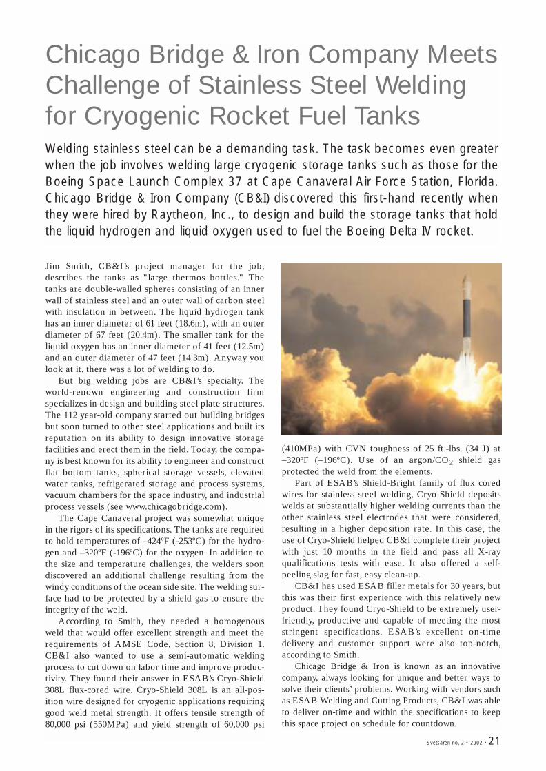
Chicago Bridge & Iron Company MeetsChallenge of Stainless Steel Weldingfor Cryogenic Rocket Fuel TanksWelding stainless steel can be a demanding task. The task becomes even greaterwhen the job involves welding large cryogenic storage tanks such as those for theBoeing Space Launch Complex 37 at Cape Canaveral Air Force Station, Florida.Chicago Bridge & Iron Company (CB&I) discovered this first-hand recently whenthey were hired by Raytheon, Inc., to design and build the storage tanks that holdthe liquid hydrogen and liquid oxygen used to fuel the Boeing Delta IV rocket.
Jim Smith, CB&I’s project manager for the job,describes the tanks as "large thermos bottles." Thetanks are double-walled spheres consisting of an innerwall of stainless steel and an outer wall of carbon steelwith insulation in between. The liquid hydrogen tankhas an inner diameter of 61 feet (18.6m), with an outerdiameter of 67 feet (20.4m). The smaller tank for theliquid oxygen has an inner diameter of 41 feet (12.5m)and an outer diameter of 47 feet (14.3m). Anyway youlook at it, there was a lot of welding to do.
But big welding jobs are CB&I’s specialty. Theworld-renown engineering and construction firmspecializes in design and building steel plate structures.The 112 year-old company started out building bridgesbut soon turned to other steel applications and built itsreputation on its ability to design innovative storagefacilities and erect them in the field. Today, the compa-ny is best known for its ability to engineer and constructflat bottom tanks, spherical storage vessels, elevatedwater tanks, refrigerated storage and process systems,vacuum chambers for the space industry, and industrialprocess vessels (see www.chicagobridge.com).
The Cape Canaveral project was somewhat uniquein the rigors of its specifications. The tanks are requiredto hold temperatures of –424ºF (-253ºC) for the hydro-gen and –320ºF (-196ºC) for the oxygen. In addition tothe size and temperature challenges, the welders soondiscovered an additional challenge resulting from thewindy conditions of the ocean side site. The welding sur-face had to be protected by a shield gas to ensure theintegrity of the weld.
According to Smith, they needed a homogenousweld that would offer excellent strength and meet therequirements of AMSE Code, Section 8, Division 1.CB&I also wanted to use a semi-automatic weldingprocess to cut down on labor time and improve produc-tivity. They found their answer in ESAB’s Cryo-Shield308L flux-cored wire. Cryo-Shield 308L is an all-pos-ition wire designed for cryogenic applications requiringgood weld metal strength. It offers tensile strength of80,000 psi (550MPa) and yield strength of 60,000 psi
(410MPa) with CVN toughness of 25 ft.-lbs. (34 J) at–320ºF (–196ºC). Use of an argon/CO2 shield gasprotected the weld from the elements.
Part of ESAB’s Shield-Bright family of flux coredwires for stainless steel welding, Cryo-Shield depositswelds at substantially higher welding currents than theother stainless steel electrodes that were considered,resulting in a higher deposition rate. In this case, theuse of Cryo-Shield helped CB&I complete their projectwith just 10 months in the field and pass all X-rayqualifications tests with ease. It also offered a self-peeling slag for fast, easy clean-up.
CB&I has used ESAB filler metals for 30 years, butthis was their first experience with this relatively newproduct. They found Cryo-Shield to be extremely user-friendly, productive and capable of meeting the moststringent specifications. ESAB’s excellent on-timedelivery and customer support were also top-notch,according to Smith.
Chicago Bridge & Iron is known as an innovativecompany, always looking for unique and better ways tosolve their clients’ problems. Working with vendors suchas ESAB Welding and Cutting Products, CB&I was ableto deliver on-time and within the specifications to keepthis space project on schedule for countdown.
Svetsaren no. 2 • 2002 • 21
22 • Svetsaren no. 2 • 2002
Welding high strength pipelines:from laboratory to fieldBy: D.J.Widgery, ESAB Group (UK) Ltd
This article was first published in the September/October issue of World Pipelines.
Although the first X80 pipelines were laid in the 1980s, it was only around theturn of the century that the next major programmes were started by Transcoand TransCanada Pipelines. Both the welding technology and the require-ments placed on the joints have moved on since the 1980s, and contractorsand welding manufacturers have had to come to terms with this.
Field welding showed up a lack of robustness in proce-dures developed in the laboratory, but new welding con-sumables were developed and performed well in the field.More work will be needed to ensure that X100 pipes canbe reliably welded, but much has already been done andmanufacturers will be ready when the pipe arrives.
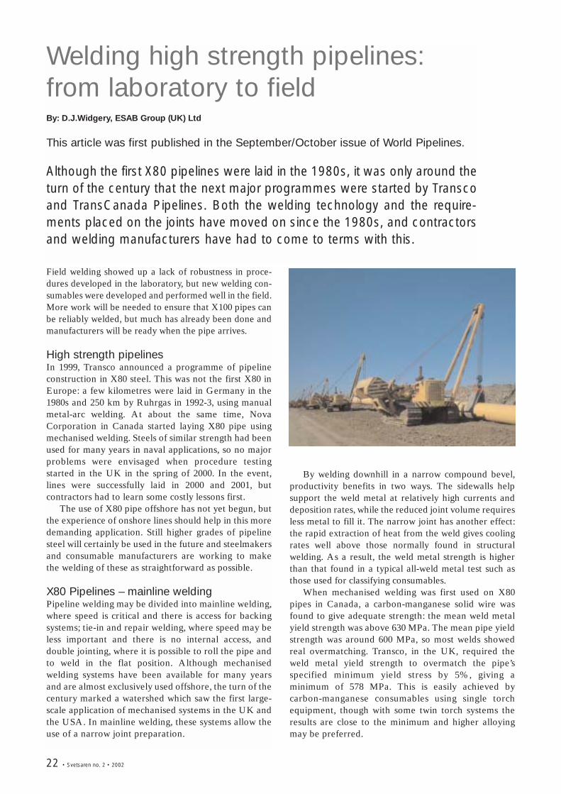
High strength pipelinesIn 1999, Transco announced a programme of pipelineconstruction in X80 steel. This was not the first X80 inEurope: a few kilometres were laid in Germany in the1980s and 250 km by Ruhrgas in 1992-3, using manualmetal-arc welding. At about the same time, NovaCorporation in Canada started laying X80 pipe usingmechanised welding. Steels of similar strength had beenused for many years in naval applications, so no majorproblems were envisaged when procedure testingstarted in the UK in the spring of 2000. In the event,lines were successfully laid in 2000 and 2001, butcontractors had to learn some costly lessons first.
The use of X80 pipe offshore has not yet begun, butthe experience of onshore lines should help in this moredemanding application. Still higher grades of pipelinesteel will certainly be used in the future and steelmakersand consumable manufacturers are working to makethe welding of these as straightforward as possible.
X80 Pipelines – mainline welding Pipeline welding may be divided into mainline welding,where speed is critical and there is access for backingsystems; tie-in and repair welding, where speed may beless important and there is no internal access, anddouble jointing, where it is possible to roll the pipe andto weld in the flat position. Although mechanisedwelding systems have been available for many yearsand are almost exclusively used offshore, the turn of thecentury marked a watershed which saw the first large-scale application of mechanised systems in the UK andthe USA. In mainline welding, these systems allow theuse of a narrow joint preparation.
By welding downhill in a narrow compound bevel,productivity benefits in two ways. The sidewalls helpsupport the weld metal at relatively high currents anddeposition rates, while the reduced joint volume requiresless metal to fill it. The narrow joint has another effect:the rapid extraction of heat from the weld gives coolingrates well above those normally found in structuralwelding. As a result, the weld metal strength is higherthan that found in a typical all-weld metal test such asthose used for classifying consumables.
When mechanised welding was first used on X80pipes in Canada, a carbon-manganese solid wire wasfound to give adequate strength: the mean weld metalyield strength was above 630 MPa. The mean pipe yieldstrength was around 600 MPa, so most welds showedreal overmatching. Transco, in the UK, required theweld metal yield strength to overmatch the pipe’sspecified minimum yield stress by 5%, giving aminimum of 578 MPa. This is easily achieved bycarbon-manganese consumables using single torchequipment, though with some twin torch systems theresults are close to the minimum and higher alloyingmay be preferred.
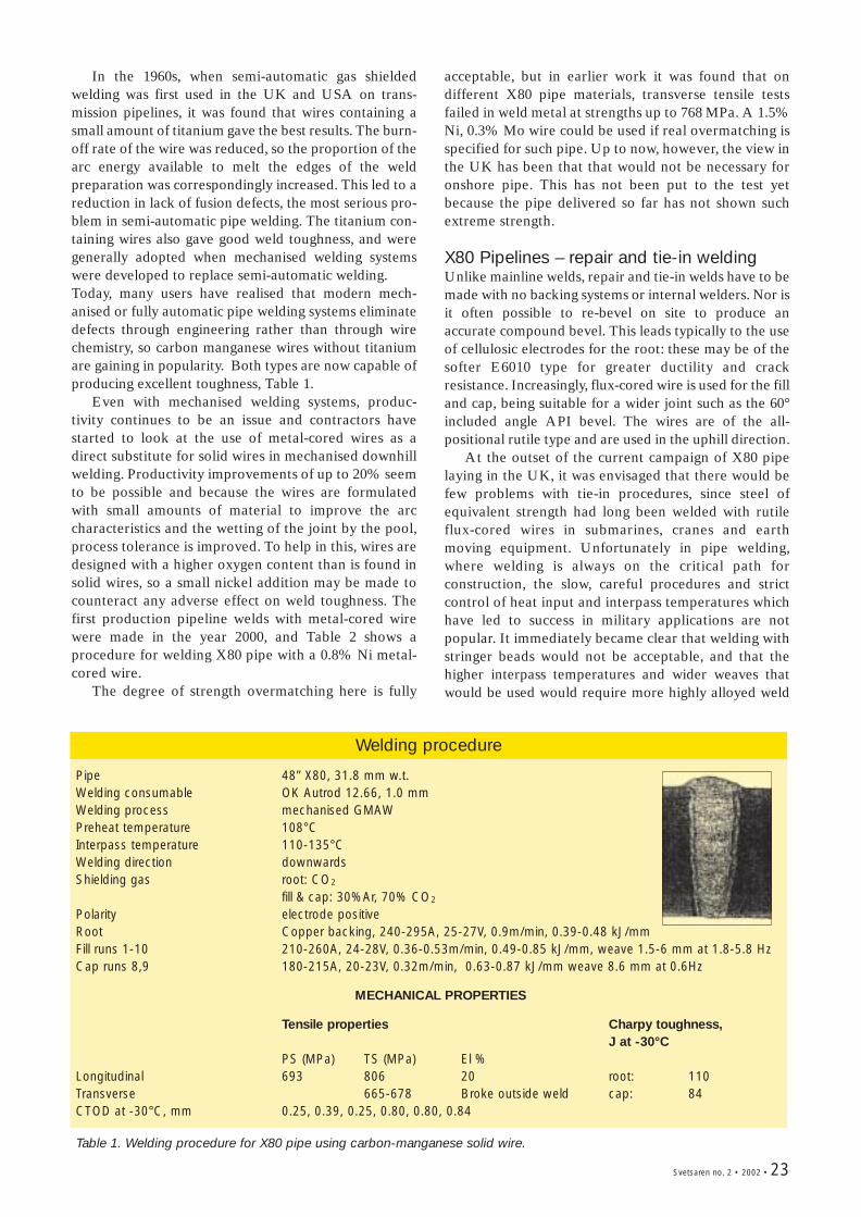
In the 1960s, when semi-automatic gas shieldedwelding was first used in the UK and USA on trans-mission pipelines, it was found that wires containing asmall amount of titanium gave the best results. The burn-off rate of the wire was reduced, so the proportion of thearc energy available to melt the edges of the weldpreparation was correspondingly increased. This led to areduction in lack of fusion defects, the most serious pro-blem in semi-automatic pipe welding. The titanium con-taining wires also gave good weld toughness, and weregenerally adopted when mechanised welding systemswere developed to replace semi-automatic welding.Today, many users have realised that modern mech-anised or fully automatic pipe welding systems eliminatedefects through engineering rather than through wirechemistry, so carbon manganese wires without titaniumare gaining in popularity. Both types are now capable ofproducing excellent toughness, Table 1.
Even with mechanised welding systems, produc-tivity continues to be an issue and contractors havestarted to look at the use of metal-cored wires as adirect substitute for solid wires in mechanised downhillwelding. Productivity improvements of up to 20% seemto be possible and because the wires are formulatedwith small amounts of material to improve the arccharacteristics and the wetting of the joint by the pool,process tolerance is improved. To help in this, wires aredesigned with a higher oxygen content than is found insolid wires, so a small nickel addition may be made tocounteract any adverse effect on weld toughness. Thefirst production pipeline welds with metal-cored wirewere made in the year 2000, and Table 2 shows aprocedure for welding X80 pipe with a 0.8% Ni metal-cored wire.
The degree of strength overmatching here is fully
Welding procedure
Pipe 48” X80, 31.8 mm w.t.Welding consumable OK Autrod 12.66, 1.0 mmWelding process mechanised GMAWPreheat temperature 108°CInterpass temperature 110-135°CWelding direction downwardsShielding gas root: CO2
fill & cap: 30%Ar, 70% CO2
Polarity electrode positiveRoot Copper backing, 240-295A, 25-27V, 0.9m/min, 0.39-0.48 kJ/mmFill runs 1-10 210-260A, 24-28V, 0.36-0.53m/min, 0.49-0.85 kJ/mm, weave 1.5-6 mm at 1.8-5.8 HzCap runs 8,9 180-215A, 20-23V, 0.32m/min, 0.63-0.87 kJ/mm weave 8.6 mm at 0.6Hz
MECHANICAL PROPERTIES
Tensile properties Charpy toughness,J at -30°C
PS (MPa) TS (MPa) El %Longitudinal 693 806 20 root: 110Transverse 665-678 Broke outside weld cap: 84CTOD at -30°C, mm 0.25, 0.39, 0.25, 0.80, 0.80, 0.84
Table 1. Welding procedure for X80 pipe using carbon-manganese solid wire.
acceptable, but in earlier work it was found that ondifferent X80 pipe materials, transverse tensile testsfailed in weld metal at strengths up to 768 MPa. A 1.5%Ni, 0.3% Mo wire could be used if real overmatching isspecified for such pipe. Up to now, however, the view inthe UK has been that that would not be necessary foronshore pipe. This has not been put to the test yetbecause the pipe delivered so far has not shown suchextreme strength.
X80 Pipelines – repair and tie-in weldingUnlike mainline welds, repair and tie-in welds have to bemade with no backing systems or internal welders. Nor isit often possible to re-bevel on site to produce anaccurate compound bevel. This leads typically to the useof cellulosic electrodes for the root: these may be of thesofter E6010 type for greater ductility and crackresistance. Increasingly, flux-cored wire is used for the filland cap, being suitable for a wider joint such as the 60°included angle API bevel. The wires are of the all-positional rutile type and are used in the uphill direction.
At the outset of the current campaign of X80 pipelaying in the UK, it was envisaged that there would befew problems with tie-in procedures, since steel ofequivalent strength had long been welded with rutileflux-cored wires in submarines, cranes and earthmoving equipment. Unfortunately in pipe welding,where welding is always on the critical path forconstruction, the slow, careful procedures and strictcontrol of heat input and interpass temperatures whichhave led to success in military applications are notpopular. It immediately became clear that welding withstringer beads would not be acceptable, and that thehigher interpass temperatures and wider weaves thatwould be used would require more highly alloyed weld
Svetsaren no. 2 • 2002 • 23
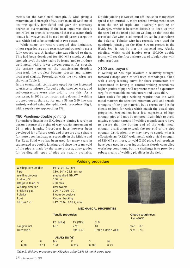
24 • Svetsaren no. 2 • 2002
metals for the same steel strength. A wire giving aminimum yield strength of 620 MPa in an all-weld-metaltest was quickly formulated and gave the necessarydegree of overmatching if the heat input was closelycontrolled. In practice, it was found that in a 16 mm thickjoint, a full weave could be used on all passes except thecap, which had to be completed in two passes.
While some contractors accepted this limitation,others regarded it as too restrictive and wanted to use afully weaved cap. A further wire was offered to them.This had been developed for 690 MPa steels. At thisstrength level, the wire had to be formulated to produceweld metal with a lower oxygen content. As a result,the surface tension of the transferring dropletsincreased, the droplets became coarser and spatterincreased slightly. Procedures with the two wires areshown in Table 3. In the event, main contractors opted for the increasedtolerance to misuse afforded by the stronger wire, andsub-contractors were also told to use this. As apostscript, in 2001 a contractor using downhill weldingdropped out at short notice and a 38 km X80 line wasentirely welded using the uphill tie-in procedure, Fig 2,with a repair rate approaching 1%.
X80 Pipelines-double jointingFor onshore lines in the UK, double jointing is rarely anoption because the rights of way restrict movement of24 m pipe lengths. Procedures have however beendeveloped for offshore work and these are also suitablefor more open landscapes, especially in the Middle andFar East. Solid wire has been used for many years insubmerged arc double jointing, and since the seam weldof the pipe is made by the same process, alloy gradesfor welding all types of pipe are readily available.
Double jointing is carried out off line, so in many casesspeed is not critical. A more recent development arisesfrom the use of triple and quadruple jointing onlaybarges, where it becomes difficult to keep up withthe speed of the fixed position welding. In that case theuse of tubular wire in submerged arc can help to redressthe balance. Tubular wire has recently been used forquadruple jointing on the Blue Stream project in theBlack Sea. It may be that the expected new Alaskapipeline, which could involve over 100,000 doublejoints, will see the first onshore use of tubular wire withsubmerged arc.
X100 and beyondIf welding of X80 pipe involves a relatively straight-forward extrapolation of well tried technologies, albeitwith a steep learning curve for those contractors notaccustomed to having to control welding procedures,higher grades of pipe will represent more of a quantumstep for consumable manufacturers and users alike. Most codes for pipe welding require that the weldmetal matches the specified minimum yield and tensilestrengths of the pipe material, but a recent trend is forclients to look for welds which match the actual pipeproperties. Steelmakers have less experience of highstrength pipe and may be tempted to aim high to avoidmissing strength targets. If welding manufacturers haveto ensure that the bottom end of the weld metalstrength distribution exceeds the top end of the pipestrength distribution, they may have to supply what iseffectively an "X120" weld metal, with a yield strengthof 830 MPa or more, to weld X100 pipe. Such productshave been used in other industries in closely controlledworkshop conditions, but the challenge is to provide arobust means of welding pipelines in the field.
Welding procedure
Welding consumable PZ 6104, 1.2 mmPipe X80, 24” x 25.8 mm wtWelding process mechanised GMAWPreheat, °C 100 minInterpass temp, °C 200 maxWelding direction downwardsShielding gas 80% Ar, 20% CO2
Polarity Electrode positiveRoot Copper backingFill runs 1-8 24V, 260A, 0.68 kJ/mm
MECHANICAL PROPERTIES
Tensile properties Charpy toughness,J at –40°C
PS (MPa) TS (MPa) El %Longitudinal 667 728 18 root: 87Transverse 608-632 Broke outside weld cap: 74
ANALYSIS (%)C Si Mn P S Ni0.08 0.59 1.68 0.012 0.008 0.73
Table 2. Welding procedure for X80 pipe using 0.8% Ni metal-cored wire.
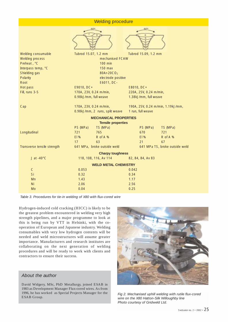
Welding procedure
Welding consumable Tubrod 15.07, 1.2 mm Tubrod 15.09, 1.2 mmWelding process mechanised FCAWPreheat , °C 100 minInterpass temp, °C 150 maxShielding gas 80Ar-20CO2
Polarity electrode positiveRoot E6011, DC-Hot pass E9010, DC+ E8010, DC+Fill, runs 3-5 170A, 23V, 0.24 m/min, 220A, 25V, 0.24 m/min,
0.98kJ/mm, full weave 1.38kJ/mm, full weave
Cap 170A, 23V, 0.24 m/min, 190A, 25V, 0.24 m/min, 1.19kJ/mm, 0.98kJ/mm, 2 runs, split weave 1 run, full weave
MECHANICAL PROPERTIESTensile properties
PS (MPa) TS (MPa) PS (MPa) TS (MPa)Longitudinal 721 765 670 721
El % R of A % El % R of A %17 63 21 67
Transverse tensile strength 641 MPa, broke outside weld 641 MPa TS, broke outside weld
Charpy toughnessJ at -40°C 118, 108, 116, Av 114 82, 84, 84, Av 83
WELD METAL CHEMISTRYC 0.053 0.042Si 0.32 0.34Mn 1.43 1.17Ni 2.06 2.56Mo 0.04 0.25
Table 3. Procedures for tie-in welding of X80 with flux-cored wire
Hydrogen-induced cold cracking (HICC) is likely to bethe greatest problem encountered in welding very highstrength pipelines, and a major programme to look atthis is being run by VTT in Helsinki, with the co-operation of European and Japanese industry. Weldingconsumables with very low hydrogen contents will beneeded and weld microstructures will assume greaterimportance. Manufacturers and research institutes arecollaborating on the next generation of weldingprocedures and will be ready to work with clients andcontractors to ensure their success.
Fig 2. Mechanised uphill welding with rutile flux-coredwire on the X80 Hatton-Silk Willoughby linePhoto courtesy of Gridweld Ltd.
Svetsaren no. 2 • 2002 • 25
About the author
David Widgery, MSc, PhD Metallurgy, joined ESAB in1983 as Development Manager Flux-cored wires. As from1996, he has worked as Special Projects Manager for theESAB Group.
26 • Svetsaren no. 2 • 2002
Synergic Cold Wire (SCW™)Submerged Arc Welding Application of a new cost efficient welding technique tostainless steels
By: Solveig Rigdal, Leif Karlsson and Lars Östgren ESAB AB, P.O. Box 8004, SE-402 77 Göteborg, Sweden
This paper was originally presented at the Stainless Steel World America 2002 Conference.
The Synergic Cold Wire (SCW™) process is a recent development of submerged arcwelding (SAW) in which a cold wire is fed in synergy with the wire electrode into theweld pool. In the present study, SCW™ has been applied for the first time to the wel-ding of 22%Cr duplex stainless steel. Experimental welds with good mechanical prop-erties and good corrosion properties were produced in a highly productive manner.
IntroductionSubmerged arc welding (SAW) is currently a well estab-lished method for welding most grades of the morewidely used stainless steels. Offering high productivity incombination with good weld quality and environmentaladvantages, SAW is an attractive method, especiallywhen it comes to welding thicker materials like those inlarge pipes and vessels, for example.
The Synergic Cold Wire (SCW) process is a recentdevelopment which was invented in 1998 (1) and offersthe chance to increase the deposition rate in submergedarc welding by more than 50%. In SCW-SAW, a cold wireis fed in synergy with the arc wire into the weld pool whereit melts (2, 3). Consequently, the arc and cold-wire depo-sition ratio always remains constant once the wirediameters have been fixed. The cold wire can be eithertrailing or leading, depending on penetration versus build-up requirements. The weld metal chemistry and depo-sition rate are thereby easily controlled and pre-selected.
The SCW process is preferably used for weldingmaterial thicknesses above approximately 8 mm, whereseveral passes are required. SCW welding can be usedwith an endless variety of combinations of solid and/orcored wires for single-, twin- (the Synergic Cold WireTwin [SCWT™] process), tandem- and multiple-wireapplications. As no arc emanates from the cold wire, itis also possible to incorporate “hard to weld”’ alloys incored wires. Further advantages include less distortiondue to a lower effective heat input, a reduced numberof weld beads and lower flux consumption incomparison with conventional SAW. SCW welding isalso very operator friendly as no additional control unit
or separate feeding device is needed.In just a short time, SCW welding has proven its advan-
tages when applied to the welding of C-Mn steels (4). Thispaper presents the first results relating to the SCW wel-ding of duplex stainless steels, illustrating the benefitsand potential of this new technique. The effect of weldingprocedure on weld metal composition and properties willbe discussed and it will be demonstrated that excellentweld metal properties can be achieved in a reliable, cost-effective and productive manner. It will also be shownthat lowering the “effective heat input”, compared withconventional SAW, makes the method particularly wellsuited to the welding of steel grades where productivity ishampered by heat input restrictions.
Experimental procedureWelds were produced in EN 1.4462 standard duplexstainless steel plate material using the SCW techniqueand were subjected to X-ray inspection, metallographicstudies, corrosion testing and mechanical testing. Inaddition, a number of welds were produced in 20 mmmild steel with conventional single-wire SAW and withSCW in order to compare deposition rates.
Duplex SCW weldsThree SCW welds were produced in duplex stainlesssteel plate material with a thickness of 14-22 mm usinga wire electrode with a diameter of 3.2 mm incombination with a cold wire with a diameter of 2.4mm. Details of joint preparation and weldingparameters are presented in Table 1 and the weld set-up is shown in Figures 1 and 2.
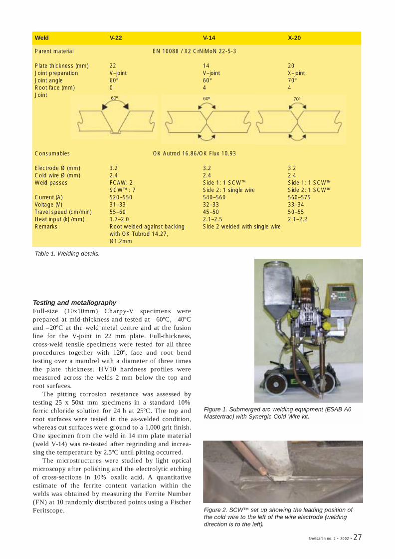
Svetsaren no. 2 • 2002 • 27
Weld V-22 V-14 X-20
Parent material EN 10088 / X2 CrNiMoN 22-5-3
Plate thickness (mm) 22 14 20Joint preparation V–joint V–joint X–jointJoint angle 60º 60º 70ºRoot face (mm) 0 4 4Joint
Consumables OK Autrod 16.86/OK Flux 10.93
Electrode Ø (mm) 3.2 3.2 3.2Cold wire Ø (mm) 2.4 2.4 2.4 Weld passes FCAW: 2 Side 1: 1 SCW™ Side 1: 1 SCW™
SCW™: 7 Side 2: 1 single wire Side 2: 1 SCW™Current (A) 520–550 540–560 560–575Voltage (V) 31–33 32–33 33–34Travel speed (cm/min) 55–60 45–50 50–55Heat input (kJ/mm) 1.7–2.0 2.1–2.5 2.1–2.2Remarks Root welded against backing Side 2 welded with single wire
with OK Tubrod 14.27, Ø1.2mm
Table 1. Welding details.
Figure 1. Submerged arc welding equipment (ESAB A6Mastertrac) with Synergic Cold Wire kit.
Figure 2. SCW™ set up showing the leading position ofthe cold wire to the left of the wire electrode (weldingdirection is to the left).
60º 60º 70º
Testing and metallography Full-size (10x10mm) Charpy-V specimens wereprepared at mid-thickness and tested at –60ºC, –40ºCand –20ºC at the weld metal centre and at the fusionline for the V-joint in 22 mm plate. Full-thickness,cross-weld tensile specimens were tested for all threeprocedures together with 120º, face and root bendtesting over a mandrel with a diameter of three timesthe plate thickness. HV10 hardness profiles weremeasured across the welds 2 mm below the top androot surfaces.
The pitting corrosion resistance was assessed bytesting 25 x 50xt mm specimens in a standard 10%ferric chloride solution for 24 h at 25ºC. The top androot surfaces were tested in the as-welded condition,whereas cut surfaces were ground to a 1,000 grit finish.One specimen from the weld in 14 mm plate material(weld V-14) was re-tested after regrinding and increa-sing the temperature by 2.5ºC until pitting occurred.
The microstructures were studied by light opticalmicroscopy after polishing and the electrolytic etchingof cross-sections in 10% oxalic acid. A quantitativeestimate of the ferrite content variation within thewelds was obtained by measuring the Ferrite Number(FN) at 10 randomly distributed points using a FischerFeritscope.
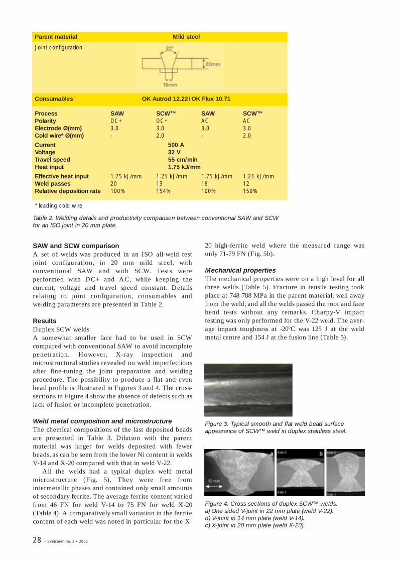
28 • Svetsaren no. 2 • 2002
Parent material Mild steel
Joint configuration
Consumables OK Autrod 12.22/OK Flux 10.71
Process SAW SCW™ SAW SCW™Polarity DC+ DC+ AC ACElectrode Ø(mm) 3.0 3.0 3.0 3.0Cold wire* Ø(mm) - 2.0 - 2.0
Current 500 AVoltage 32 VTravel speed 55 cm/minHeat input 1.75 kJ/mm
Effective heat input 1.75 kJ/mm 1.21 kJ/mm 1.75 kJ/mm 1.21 kJ/mmWeld passes 20 13 18 12Relative deposition rate 100% 154% 100% 150%
* leading cold wire
Table 2. Welding details and productivity comparison between conventional SAW and SCW for an ISO joint in 20 mm plate.
Figure 3. Typical smooth and flat weld bead surfaceappearance of SCW™ weld in duplex stainless steel.
Figure 4. Cross sections of duplex SCW™ welds. a) One sided V-joint in 22 mm plate (weld V-22). b) V-joint in 14 mm plate (weld V-14). c) X-joint in 20 mm plate (weld X-20).
SAW and SCW comparisonA set of welds was produced in an ISO all-weld testjoint configuration, in 20 mm mild steel, withconventional SAW and with SCW. Tests wereperformed with DC+ and AC, while keeping thecurrent, voltage and travel speed constant. Detailsrelating to joint configuration, consumables andwelding parameters are presented in Table 2.
ResultsDuplex SCW weldsA somewhat smaller face had to be used in SCWcompared with conventional SAW to avoid incompletepenetration. However, X-ray inspection andmicrostructural studies revealed no weld imperfectionsafter fine-tuning the joint preparation and weldingprocedure. The possibility to produce a flat and evenbead profile is illustrated in Figures 3 and 4. The cross-sections in Figure 4 show the absence of defects such aslack of fusion or incomplete penetration.
Weld metal composition and microstructureThe chemical compositions of the last deposited beadsare presented in Table 3. Dilution with the parentmaterial was larger for welds deposited with fewerbeads, as can be seen from the lower Ni content in weldsV-14 and X-20 compared with that in weld V-22.
All the welds had a typical duplex weld metalmicrostructure (Fig. 5). They were free fromintermetallic phases and contained only small amountsof secondary ferrite. The average ferrite content variedfrom 46 FN for weld V-14 to 75 FN for weld X-20(Table 4). A comparatively small variation in the ferritecontent of each weld was noted in particular for the X-
20 high-ferrite weld where the measured range wasonly 71-79 FN (Fig. 5b).
Mechanical propertiesThe mechanical properties were on a high level for allthree welds (Table 5). Fracture in tensile testing tookplace at 748-788 MPa in the parent material, well awayfrom the weld, and all the welds passed the root and facebend tests without any remarks. Charpy-V impacttesting was only performed for the V-22 weld. The aver-age impact toughness at -20ºC was 125 J at the weldmetal centre and 154 J at the fusion line (Table 5).
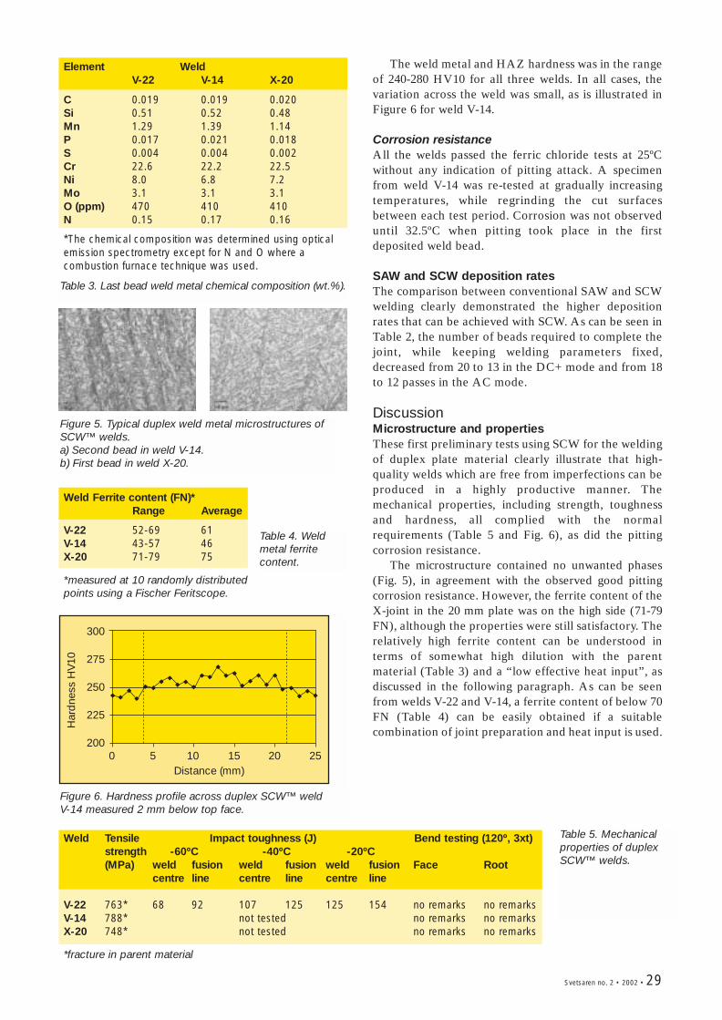
Svetsaren no. 2 • 2002 • 29
The weld metal and HAZ hardness was in the rangeof 240-280 HV10 for all three welds. In all cases, thevariation across the weld was small, as is illustrated inFigure 6 for weld V-14.
Corrosion resistanceAll the welds passed the ferric chloride tests at 25ºCwithout any indication of pitting attack. A specimenfrom weld V-14 was re-tested at gradually increasingtemperatures, while regrinding the cut surfacesbetween each test period. Corrosion was not observeduntil 32.5ºC when pitting took place in the firstdeposited weld bead.
SAW and SCW deposition ratesThe comparison between conventional SAW and SCWwelding clearly demonstrated the higher depositionrates that can be achieved with SCW. As can be seen inTable 2, the number of beads required to complete thejoint, while keeping welding parameters fixed,decreased from 20 to 13 in the DC+ mode and from 18to 12 passes in the AC mode.
DiscussionMicrostructure and propertiesThese first preliminary tests using SCW for the weldingof duplex plate material clearly illustrate that high-quality welds which are free from imperfections can beproduced in a highly productive manner. Themechanical properties, including strength, toughnessand hardness, all complied with the normalrequirements (Table 5 and Fig. 6), as did the pittingcorrosion resistance.
The microstructure contained no unwanted phases(Fig. 5), in agreement with the observed good pittingcorrosion resistance. However, the ferrite content of theX-joint in the 20 mm plate was on the high side (71-79FN), although the properties were still satisfactory. Therelatively high ferrite content can be understood interms of somewhat high dilution with the parentmaterial (Table 3) and a “low effective heat input”, asdiscussed in the following paragraph. As can be seenfrom welds V-22 and V-14, a ferrite content of below 70FN (Table 4) can be easily obtained if a suitablecombination of joint preparation and heat input is used.
Figure 5. Typical duplex weld metal microstructures ofSCW™ welds. a) Second bead in weld V-14. b) First bead in weld X-20.
Weld Ferrite content (FN)*Range Average
V-22 52-69 61V-14 43-57 46X-20 71-79 75
*measured at 10 randomly distributedpoints using a Fischer Feritscope.
Weld Tensile Impact toughness (J) Bend testing (120º, 3xt)strength -60ºC -40ºC -20ºC(MPa) weld fusion weld fusion weld fusion Face Root
centre line centre line centre line
V-22 763* 68 92 107 125 125 154 no remarks no remarksV-14 788* not tested no remarks no remarksX-20 748* not tested no remarks no remarks
*fracture in parent material
0 5 10 15 20 25
300
275
250
225
200
Distance (mm)
Har
dne
ss H
V10
Figure 6. Hardness profile across duplex SCW™ weld V-14 measured 2 mm below top face.
Table 3. Last bead weld metal chemical composition (wt.%).
Element WeldV-22 V-14 X-20
C 0.019 0.019 0.020Si 0.51 0.52 0.48Mn 1.29 1.39 1.14P 0.017 0.021 0.018S 0.004 0.004 0.002Cr 22.6 22.2 22.5Ni 8.0 6.8 7.2Mo 3.1 3.1 3.1O (ppm) 470 410 410N 0.15 0.17 0.16
*The chemical composition was determined using opticalemission spectrometry except for N and O where acombustion furnace technique was used.
Table 4. Weldmetal ferritecontent.
Table 5. Mechanicalproperties of duplexSCW™ welds.
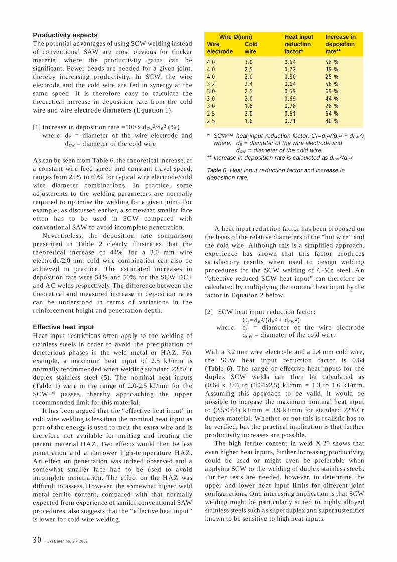
30 • Svetsaren no. 2 • 2002
Productivity aspectsThe potential advantages of using SCW welding insteadof conventional SAW are most obvious for thickermaterial where the productivity gains can besignificant. Fewer beads are needed for a given joint,thereby increasing productivity. In SCW, the wireelectrode and the cold wire are fed in synergy at thesame speed. It is therefore easy to calculate thetheoretical increase in deposition rate from the coldwire and wire electrode diameters (Equation 1).
[1] Increase in deposition rate =100 x dcw2/de2 (%)where: de = diameter of the wire electrode and
dcw = diameter of the cold wire
As can be seen from Table 6, the theoretical increase, ata constant wire feed speed and constant travel speed,ranges from 25% to 69% for typical wire electrode/coldwire diameter combinations. In practice, someadjustments to the welding parameters are normallyrequired to optimise the welding for a given joint. Forexample, as discussed earlier, a somewhat smaller faceoften has to be used in SCW compared withconventional SAW to avoid incomplete penetration.
Nevertheless, the deposition rate comparisonpresented in Table 2 clearly illustrates that thetheoretical increase of 44% for a 3.0 mm wireelectrode/2.0 mm cold wire combination can also beachieved in practice. The estimated increases indeposition rate were 54% and 50% for the SCW DC+and AC welds respectively. The difference between thetheoretical and measured increase in deposition ratescan be understood in terms of variations in thereinforcement height and penetration depth.
Effective heat inputHeat input restrictions often apply to the welding ofstainless steels in order to avoid the precipitation ofdeleterious phases in the weld metal or HAZ. Forexample, a maximum heat input of 2.5 kJ/mm isnormally recommended when welding standard 22%Crduplex stainless steel (5). The nominal heat inputs(Table 1) were in the range of 2.0-2.5 kJ/mm for theSCW™ passes, thereby approaching the upperrecommended limit for this material.
It has been argued that the “effective heat input” incold wire welding is less than the nominal heat input aspart of the energy is used to melt the extra wire and istherefore not available for melting and heating theparent material HAZ. Two effects would then be lesspenetration and a narrower high-temperature HAZ.An effect on penetration was indeed observed and asomewhat smaller face had to be used to avoidincomplete penetration. The effect on the HAZ wasdifficult to assess. However, the somewhat higher weldmetal ferrite content, compared with that normallyexpected from experience of similar conventional SAWprocedures, also suggests that the “effective heat input”is lower for cold wire welding.
Wire Ø(mm) Heat input Increase inWire Cold reduction deposition electrode wire factor* rate**
4.0 3.0 0.64 56 %4.0 2.5 0.72 39 %4.0 2.0 0.80 25 %3.2 2.4 0.64 56 %3.0 2.5 0.59 69 %3.0 2.0 0.69 44 %3.0 1.6 0.78 28 %2.5 2.0 0.61 64 %2.5 1.6 0.71 40 %
* SCW™ heat input reduction factor: Cf =de2/(de2 + dcw2) where: de = diameter of the wire electrode and
dcw = diameter of the cold wire.** Increase in deposition rate is calculated as dcw2/de2
Table 6. Heat input reduction factor and increase indeposition rate.
A heat input reduction factor has been proposed onthe basis of the relative diameters of the “hot wire” andthe cold wire. Although this is a simplified approach,experience has shown that this factor producessatisfactory results when used to design weldingprocedures for the SCW welding of C-Mn steel. An“effective reduced SCW heat input” can therefore becalculated by multiplying the nominal heat input by thefactor in Equation 2 below.
[2] SCW heat input reduction factor: Cf =de2/(de2 + dcw2)
where: de = diameter of the wire electrodedcw = diameter of the cold wire.
With a 3.2 mm wire electrode and a 2.4 mm cold wire,the SCW heat input reduction factor is 0.64 (Table 6). The range of effective heat inputs for theduplex SCW welds can then be calculated as (0.64 x 2.0) to (0.64x2.5) kJ/mm = 1.3 to 1.6 kJ/mm.Assuming this approach to be valid, it would bepossible to increase the maximum nominal heat inputto (2.5/0.64) kJ/mm = 3.9 kJ/mm for standard 22%Crduplex material. Whether or not this is realistic has tobe verified, but the practical implication is that furtherproductivity increases are possible.
The high ferrite content in weld X-20 shows thateven higher heat inputs, further increasing productivity,could be used or might even be preferable whenapplying SCW to the welding of duplex stainless steels.Further tests are needed, however, to determine theupper and lower heat input limits for different jointconfigurations. One interesting implication is that SCWwelding might be particularly suited to highly alloyedstainless steels such as superduplex and superausteniticsknown to be sensitive to high heat inputs.
Svetsaren no. 2 • 2002 • 31
ConclusionsThe SCW process offers an opportunity to increase thedeposition rate in submerged arc welding by more than50%. Good agreement was found between thetheoretical and measured increase in deposition rate in20 mm plate material.
• Synergic cold wire submerged arc welding (SCW)has been applied successfully to the welding of22%Cr duplex 14-22 mm plate material.
• High-quality welds with good mechanical propertiesand good corrosion properties were produced in ahighly productive manner.
• No intermetallic phases or significant amounts ofsecondary austenite were detected.
• The smaller penetration and higher ferrite contentthan expected from experience of conventionalSAW suggest that the effective heat input is lower inSCW. An approximate SCW heat input reductionfactor is therefore proposed on the basis of theelectrode and cold wire dimensions.
• SCW is well suited to the welding of stainless steelsand might, as a result of the lower effective heatinput, be particularly well suited to welding gradessensitive to high heat inputs.
AcknowledgementsThe skilful application of SCW to duplex stainless steelby Vital Batista (ESAB AB, Sweden) is gratefullyacknowledged. Lars Östgren and Lennart Wittung(ESAB AB, Sweden) are thanked for valuable discus-sions and for proposing the heat input reduction factor.
About the authors
Solveig Rigdal, MSc, EWE, joined ESAB in 1982 and hassince then worked with product development and marketsupport within the R & D department in Gothenburg.During the last years, her main focus has been submergedarc welding of stainless and high alloyed steels and stripcladding.
Dr. Leif Karlsson joined ESAB's R&D department in1986, after receiving a Ph.D. in materials science fromChalmers University of Technology. He currently holds aposition as Manager of Research Projects at ESAB AB inSweden, focussing on projects dealing with corrosionresistant alloys and high strength steels.
Lars Östgren is Marketing Manager at ESABGothenburg, responsible for the industrial segmentPipemills. He invented the SCW submerged arc welding.
References1. Invented 1998 by Lars Östgren, marketing manager
for pipe mills at ESAB AB, Sweden.2. ESAB information folder, “A6 Synergic Cold Wire,
The ESAB A6 – SCW SAW process”.3. ESAB information folder, “Fluxes and wires for
Submerged Arc Welding”, 2000, p.40.4. P. Kjällström and S. Hilal, ESAB Forum, No. 3
October 2000, p.12. 5. EN 1011-3, “Welding – recommendations for
welding of metallic materials – Part 3: Arc weldingof stainless steels”.
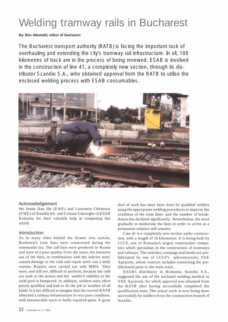
32 • Svetsaren no. 2 • 2002
Welding tramway rails in BucharestBy: Ben Altemühl, editor of Svetsaren
The Bucharest transport authority (RATB) is facing the important task ofoverhauling and extending the city’s tramway rail infrastructure. In all, 100kilometres of track are in the process of being renewed. ESAB is involvedin the construction of line 41, a completely new section, through its dis-tributor Scandio S.A., who obtained approval from the RATB to utilise theenclosed welding process with ESAB consumables.
AcknowledgementWe thank Dan Ilie (EWE) and Laurentiu Chiritescu(EWE) of Scandio SA. and Cristian Gheorghe of ESABRomania for their valuable help in composing thisarticle.
IntroductionAs in many cities behind the former iron curtain,Bucharest’s tram lines were constructed during thecommunist era. The rail bars were produced in Russiaand were of a poor quality. Over the years, the intensiveuse of the lines, in combination with the inferior steel,caused damage to the rails and repair work was a dailyroutine. Repairs were carried out with MMA. Theywere, and still are, difficult to perform, because the railsare sunk in the streets and the welder’s visibility at theweld pool is hampered. In addition, welders were oftenpoorly qualified and had to do the job in weather of allkinds. It is not difficult to imagine that the current RATBinherited a railway infrastructure in very poor condition,with innumerable worn or badly repaired spots. A great
deal of work has since been done by qualified weldersusing the appropriate welding procedures to improve thecondition of the tram lines and the number of break-downs has declined significantly. Nevertheless, the needgradually to modernise the lines in order to arrive at apermanent solution still remains.
Line 41 is a completely new section under construc-tion, with a length of 16 kilometres. It is being built byCCCF, one of Romania’s largest construction compa-nies which specialises in the construction of tramwaysand railways. The switches, crossings and bends are pre-fabricated by one of CCCF’s subcontractors, VAEApcarom, whose contract includes connecting the pre-fabricated parts to the main track.
ESAB’s distributor in Romania, Scandio S.A.,suggested the use of the enclosed welding method toVAE Apcarom, for which approval was obtained fromthe RATB after having successfully completed thequalification tests. The actual work is now being donesuccessfully by welders from the construction branch ofScandio.
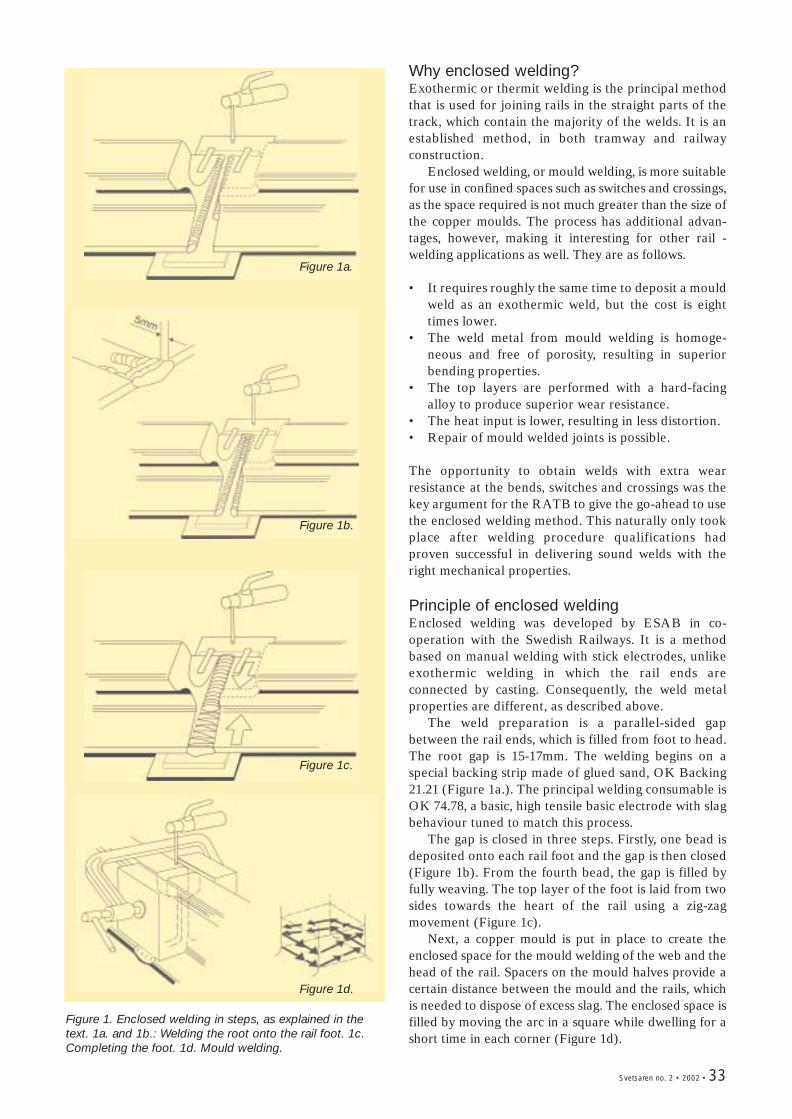
Svetsaren no. 2 • 2002 • 33
Why enclosed welding?Exothermic or thermit welding is the principal methodthat is used for joining rails in the straight parts of thetrack, which contain the majority of the welds. It is anestablished method, in both tramway and railwayconstruction.
Enclosed welding, or mould welding, is more suitablefor use in confined spaces such as switches and crossings,as the space required is not much greater than the size ofthe copper moulds. The process has additional advan-tages, however, making it interesting for other rail -welding applications as well. They are as follows.
• It requires roughly the same time to deposit a mouldweld as an exothermic weld, but the cost is eighttimes lower.
• The weld metal from mould welding is homoge-neous and free of porosity, resulting in superiorbending properties.
• The top layers are performed with a hard-facingalloy to produce superior wear resistance.
• The heat input is lower, resulting in less distortion.• Repair of mould welded joints is possible.
The opportunity to obtain welds with extra wearresistance at the bends, switches and crossings was thekey argument for the RATB to give the go-ahead to usethe enclosed welding method. This naturally only tookplace after welding procedure qualifications hadproven successful in delivering sound welds with theright mechanical properties.
Principle of enclosed weldingEnclosed welding was developed by ESAB in co-operation with the Swedish Railways. It is a methodbased on manual welding with stick electrodes, unlikeexothermic welding in which the rail ends areconnected by casting. Consequently, the weld metalproperties are different, as described above.
The weld preparation is a parallel-sided gapbetween the rail ends, which is filled from foot to head.The root gap is 15-17mm. The welding begins on aspecial backing strip made of glued sand, OK Backing21.21 (Figure 1a.). The principal welding consumable isOK 74.78, a basic, high tensile basic electrode with slagbehaviour tuned to match this process.
The gap is closed in three steps. Firstly, one bead isdeposited onto each rail foot and the gap is then closed(Figure 1b). From the fourth bead, the gap is filled byfully weaving. The top layer of the foot is laid from twosides towards the heart of the rail using a zig-zagmovement (Figure 1c).
Next, a copper mould is put in place to create theenclosed space for the mould welding of the web and thehead of the rail. Spacers on the mould halves provide acertain distance between the mould and the rails, whichis needed to dispose of excess slag. The enclosed space isfilled by moving the arc in a square while dwelling for ashort time in each corner (Figure 1d).
Figure 1. Enclosed welding in steps, as explained in thetext. 1a. and 1b.: Welding the root onto the rail foot. 1c.Completing the foot. 1d. Mould welding.
Figure 1a.
Figure 1b.
Figure 1c.
Figure 1d.
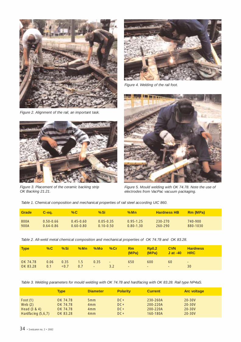
34 • Svetsaren no. 2 • 2002
Table 1. Chemical composition and mechanical properties of rail steel according UIC 860.
Grade C-eq. %C %Si %Mn Hardness HB Rm (MPa)
800A 0.50-0.66 0.45-0.60 0.05-0.35 0.95-1.25 230-270 740-900900A 0.64-0.86 0.60-0.80 0.10-0.50 0.80-1.30 260-290 880-1030
Table 2. All-weld metal chemical composition and mechanical properties of OK 74.78 and OK 83.28.
Type %C %Si %Mn %Mo %Cr Rm Rp0.2 CVN Hardness(MPa) (MPa) J at -40 HRC
OK 74.78 0.06 0.35 1.5 0.35 - 650 600 60 -OK 83.28 0.1 <0.7 0.7 - 3.2 - - - 30
Table 3. Welding parameters for mould welding with OK 74.78 and hardfacing with OK 83.28. Rail type NP4aS.
Type Diameter Polarity Current Arc voltage
Foot (1) OK 74.78 5mm DC+ 230-260A 20-30VWeb (2) OK 74.78 4mm DC+ 200-220A 20-30VHead (3 & 4) OK 74.78 4mm DC+ 200-220A 20-30VHardfacing (5,6,7) OK 83.28 4mm DC+ 160-180A 20-30V
Figure 3. Placement of the ceramic backing strip OK Backing 21.21.
Figure 4. Welding of the rail foot.
Figure 5. Mould welding with OK 74.78. Note the use ofelectrodes from VacPac vacuum packaging.
Figure 2. Alignment of the rail, an important task.
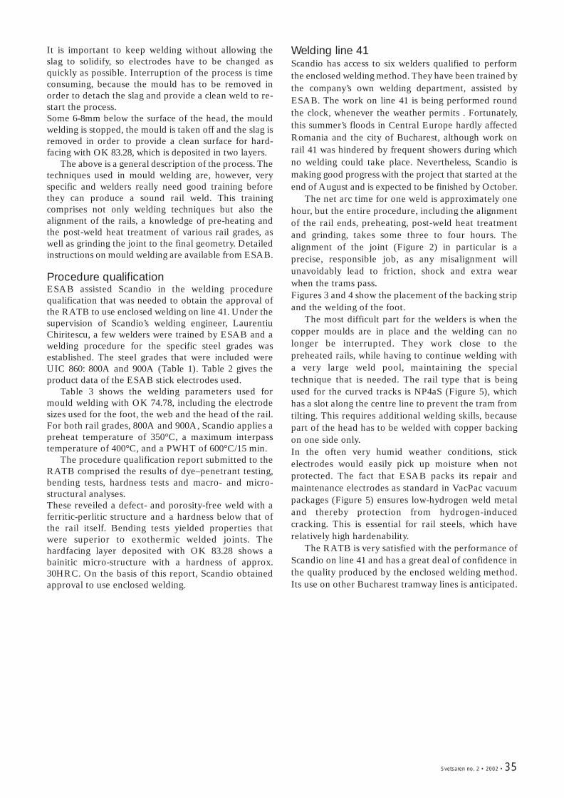
Svetsaren no. 2 • 2002 • 35
It is important to keep welding without allowing theslag to solidify, so electrodes have to be changed asquickly as possible. Interruption of the process is timeconsuming, because the mould has to be removed inorder to detach the slag and provide a clean weld to re-start the process.Some 6-8mm below the surface of the head, the mouldwelding is stopped, the mould is taken off and the slag isremoved in order to provide a clean surface for hard-facing with OK 83.28, which is deposited in two layers.
The above is a general description of the process. Thetechniques used in mould welding are, however, veryspecific and welders really need good training beforethey can produce a sound rail weld. This trainingcomprises not only welding techniques but also thealignment of the rails, a knowledge of pre-heating andthe post-weld heat treatment of various rail grades, aswell as grinding the joint to the final geometry. Detailedinstructions on mould welding are available from ESAB.
Procedure qualificationESAB assisted Scandio in the welding procedurequalification that was needed to obtain the approval ofthe RATB to use enclosed welding on line 41. Under thesupervision of Scandio’s welding engineer, LaurentiuChiritescu, a few welders were trained by ESAB and awelding procedure for the specific steel grades wasestablished. The steel grades that were included wereUIC 860: 800A and 900A (Table 1). Table 2 gives theproduct data of the ESAB stick electrodes used.
Table 3 shows the welding parameters used formould welding with OK 74.78, including the electrodesizes used for the foot, the web and the head of the rail. For both rail grades, 800A and 900A, Scandio applies apreheat temperature of 350°C, a maximum interpasstemperature of 400°C, and a PWHT of 600°C/15 min.
The procedure qualification report submitted to theRATB comprised the results of dye–penetrant testing,bending tests, hardness tests and macro- and micro-structural analyses.These reveiled a defect- and porosity-free weld with aferritic-perlitic structure and a hardness below that ofthe rail itself. Bending tests yielded properties thatwere superior to exothermic welded joints. Thehardfacing layer deposited with OK 83.28 shows abainitic micro-structure with a hardness of approx.30HRC. On the basis of this report, Scandio obtainedapproval to use enclosed welding.
Welding line 41Scandio has access to six welders qualified to performthe enclosed welding method. They have been trained bythe company’s own welding department, assisted byESAB. The work on line 41 is being performed roundthe clock, whenever the weather permits . Fortunately,this summer’s floods in Central Europe hardly affectedRomania and the city of Bucharest, although work onrail 41 was hindered by frequent showers during whichno welding could take place. Nevertheless, Scandio ismaking good progress with the project that started at theend of August and is expected to be finished by October.
The net arc time for one weld is approximately onehour, but the entire procedure, including the alignmentof the rail ends, preheating, post-weld heat treatmentand grinding, takes some three to four hours. Thealignment of the joint (Figure 2) in particular is aprecise, responsible job, as any misalignment willunavoidably lead to friction, shock and extra wearwhen the trams pass.Figures 3 and 4 show the placement of the backing stripand the welding of the foot.
The most difficult part for the welders is when thecopper moulds are in place and the welding can nolonger be interrupted. They work close to thepreheated rails, while having to continue welding witha very large weld pool, maintaining the specialtechnique that is needed. The rail type that is beingused for the curved tracks is NP4aS (Figure 5), whichhas a slot along the centre line to prevent the tram fromtilting. This requires additional welding skills, becausepart of the head has to be welded with copper backingon one side only.In the often very humid weather conditions, stickelectrodes would easily pick up moisture when notprotected. The fact that ESAB packs its repair andmaintenance electrodes as standard in VacPac vacuumpackages (Figure 5) ensures low-hydrogen weld metaland thereby protection from hydrogen-inducedcracking. This is essential for rail steels, which haverelatively high hardenability.
The RATB is very satisfied with the performance ofScandio on line 41 and has a great deal of confidence inthe quality produced by the enclosed welding method.Its use on other Bucharest tramway lines is anticipated.
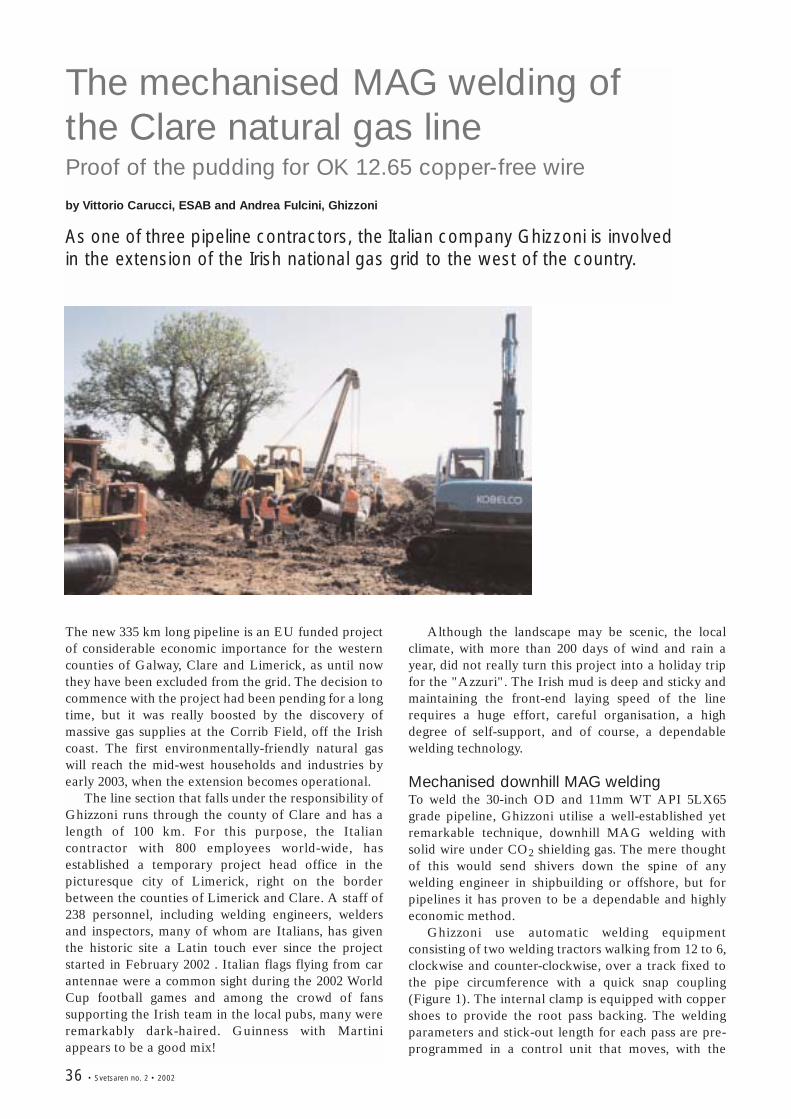
36 • Svetsaren no. 2 • 2002
The mechanised MAG welding ofthe Clare natural gas lineProof of the pudding for OK 12.65 copper-free wire
by Vittorio Carucci, ESAB and Andrea Fulcini, Ghizzoni
As one of three pipeline contractors, the Italian company Ghizzoni is involvedin the extension of the Irish national gas grid to the west of the country.
The new 335 km long pipeline is an EU funded projectof considerable economic importance for the westerncounties of Galway, Clare and Limerick, as until nowthey have been excluded from the grid. The decision tocommence with the project had been pending for a longtime, but it was really boosted by the discovery ofmassive gas supplies at the Corrib Field, off the Irishcoast. The first environmentally-friendly natural gaswill reach the mid-west households and industries byearly 2003, when the extension becomes operational.
The line section that falls under the responsibility ofGhizzoni runs through the county of Clare and has alength of 100 km. For this purpose, the Italiancontractor with 800 employees world-wide, hasestablished a temporary project head office in thepicturesque city of Limerick, right on the borderbetween the counties of Limerick and Clare. A staff of238 personnel, including welding engineers, weldersand inspectors, many of whom are Italians, has giventhe historic site a Latin touch ever since the projectstarted in February 2002 . Italian flags flying from carantennae were a common sight during the 2002 WorldCup football games and among the crowd of fanssupporting the Irish team in the local pubs, many wereremarkably dark-haired. Guinness with Martiniappears to be a good mix!
Although the landscape may be scenic, the localclimate, with more than 200 days of wind and rain ayear, did not really turn this project into a holiday tripfor the "Azzuri". The Irish mud is deep and sticky andmaintaining the front-end laying speed of the linerequires a huge effort, careful organisation, a highdegree of self-support, and of course, a dependablewelding technology.
Mechanised downhill MAG weldingTo weld the 30-inch OD and 11mm WT API 5LX65grade pipeline, Ghizzoni utilise a well-established yetremarkable technique, downhill MAG welding withsolid wire under CO2 shielding gas. The mere thoughtof this would send shivers down the spine of anywelding engineer in shipbuilding or offshore, but forpipelines it has proven to be a dependable and highlyeconomic method.
Ghizzoni use automatic welding equipmentconsisting of two welding tractors walking from 12 to 6,clockwise and counter-clockwise, over a track fixed tothe pipe circumference with a quick snap coupling(Figure 1). The internal clamp is equipped with coppershoes to provide the root pass backing. The weldingparameters and stick-out length for each pass are pre-programmed in a control unit that moves, with the
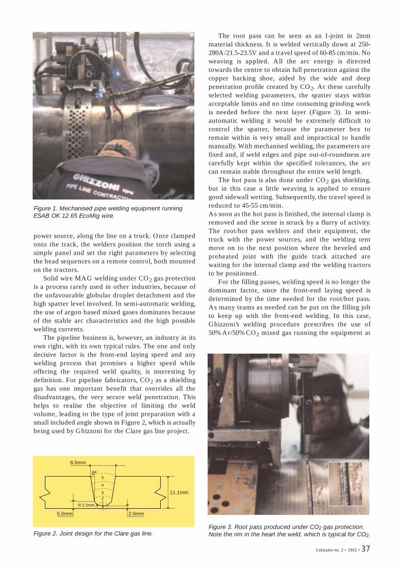
Svetsaren no. 2 • 2002 • 37
Figure 1. Mechanised pipe welding equipment runningESAB OK 12.65 EcoMig wire.
11.1mm
8.5mm
5.0mm 2.0mm
R 3.2mm
8º5
4
3
21
Figure 2. Joint design for the Clare gas line.Figure 3. Root pass produced under CO2 gas protection.Note the rim in the heart the weld, which is typical for CO2.
power source, along the line on a truck. Once clampedonto the track, the welders position the torch using asimple panel and set the right parameters by selectingthe bead sequences on a remote control, both mountedon the tractors.
Solid wire MAG welding under CO2 gas protectionis a process rarely used in other industries, because ofthe unfavourable globular droplet detachment and thehigh spatter level involved. In semi-automatic welding,the use of argon based mixed gases dominates becauseof the stable arc characteristics and the high possiblewelding currents.
The pipeline business is, however, an industry in itsown right, with its own typical rules. The one and onlydecisive factor is the front-end laying speed and anywelding process that promises a higher speed whileoffering the required weld quality, is interesting bydefinition. For pipeline fabricators, CO2 as a shieldinggas has one important benefit that overrides all thedisadvantages, the very secure weld penetration. Thishelps to realise the objective of limiting the weldvolume, leading to the type of joint preparation with asmall included angle shown in Figure 2, which is actuallybeing used by Ghizzoni for the Clare gas line project.
The root pass can be seen as an I-joint in 2mmmaterial thickness. It is welded vertically down at 250-280A/21.5-23.5V and a travel speed of 60-85 cm/min. Noweaving is applied. All the arc energy is directedtowards the centre to obtain full penetration against thecopper backing shoe, aided by the wide and deeppenetration profile created by CO2. At these carefullyselected welding parameters, the spatter stays withinacceptable limits and no time consuming grinding workis needed before the next layer (Figure 3). In semi-automatic welding it would be extremely difficult tocontrol the spatter, because the parameter box toremain within is very small and impractical to handlemanually. With mechanised welding, the parameters arefixed and, if weld edges and pipe out-of-roundness arecarefully kept within the specified tolerances, the arccan remain stable throughout the entire weld length.
The hot pass is also done under CO2 gas shielding,but in this case a little weaving is applied to ensuregood sidewall wetting. Subsequently, the travel speed isreduced to 45-55 cm/min. As soon as the hot pass is finished, the internal clamp isremoved and the scene is struck by a flurry of activity.The root/hot pass welders and their equipment, thetruck with the power sources, and the welding tentmove on to the next position where the beveled andpreheated joint with the guide track attached arewaiting for the internal clamp and the welding tractorsto be positioned.
For the filling passes, welding speed is no longer thedominant factor, since the front-end laying speed isdetermined by the time needed for the root/hot pass.As many teams as needed can be put on the filling jobto keep up with the front-end welding. In this case,Ghizzoni’s welding procedure prescribes the use of50%Ar/50%CO2 mixed gas running the equipment at
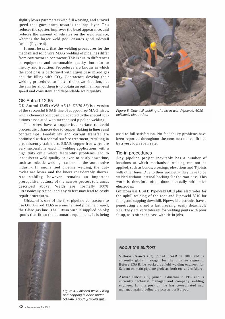
38 • Svetsaren no. 2 • 2002
Figure 4. Finished weld. Fillingand capping is done under50%Ar/50%CO2 mixed gas.
Figure 5. Downhill welding of a tie-in with Pipeweld 6010cellulosic electrodes.
About the authors
Vittorio Carucci (33) joined ESAB in 2000 and iscurrently global manager for the pipeline segment.Before ESAB, he worked as field welding engineer forSaipem on main pipeline projects, both on- and offshore.
Andrea Fulcini (36) joined Ghizzoni in 1987 and iscurrently technical manager and company weldingengineer. In this position, he has co-ordinated andmanaged main pipeline projects across Europe.
slightly lower parameters with full weaving, and a travelspeed that goes down towards the cap layer. Thisreduces the spatter, improves the bead appearance, andreduces the amount of silicates on the weld surface,whereas the larger weld pool ensures good sidewallfusion (Figure 4).
It must be said that the welding procedures for themechanised solid wire MAG welding of pipelines differfrom contractor to contractor. This is due to differencesin equipment and consumable quality, but also tohistory and tradition. Procedures are known in whichthe root pass is performed with argon base mixed gasand the filling with CO2. Contractors develop theirwelding procedures to match their own situation, butthe aim for all of them is to obtain an optimal front-endspeed and consistent and dependable weld quality.
OK Autrod 12.65 OK Autrod 12.65 (AWS A5.18: ER70-S6) is a versionof the successful ESAB line of copper-free MAG wires,with a chemical composition adapted to the special con-ditions associated with mechanised pipeline welding.
The wires have a copper-free surface to avoidprocess disturbances due to copper flaking in liners andcontact tips. Feedability and current transfer areoptimised with a special surface treatment, resulting ina consistently stable arc. ESAB copper-free wires arevery successfully used in welding applications with ahigh duty cycle where feedability problems lead toinconsistent weld quality or even to costly downtime,such as robotic welding stations in the automotiveindustry. In mechanised pipeline welding, the dutycycles are lower and the liners considerably shorter.Arc stability, however, remains an importantprerequisite, because of the narrow process tolerancesdescribed above. Welds are normally 100%ultrasonically tested, and any defect may lead to costlyrepair procedures.
Ghizzoni is one of the first pipeline contractors touse OK Autrod 12.65 in a mechanised pipeline project,the Clare gas line. The 1.0mm wire is supplied on 5kgspools that fit on the automatic equipment. It is being
used to full satisfaction. No feedability problems havebeen reported throughout the construction, confirmedby a very low repair rate.
Tie-in proceduresAny pipeline project inevitably has a number oflocations at which mechanised welding can not beapplied, such as bends, crossings, elevations and T-jointswith other lines. Due to their geometry, they have to bewelded without internal backing for the root pass. Thiswork is therefore often done manually with stickelectrodes. Ghizzoni use ESAB Pipeweld 6010 plus electrodes forthe uphill welding of the root and Pipeweld 8010 forfilling and capping downhill. Pipeweld electrodes have apenetrating arc and a fast freezing, easily detachableslag. They are very tolerant for welding joints with poorfit-up, as is often the case with tie-in jobs.
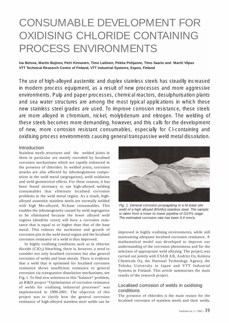
Svetsaren no. 2 • 2002 • 39
CONSUMABLE DEVELOPMENT FOROXIDISING CHLORIDE CONTAININGPROCESS ENVIRONMENTSIva Betova, Martin Bojinov, Petri Kinnunen, Timo Laitinen, Pekka Pohjanne, Timo Saario and Martti VilpasVTT Technical Research Centre of Finland, VTT Industrial Systems, Espoo, Finland
The use of high-alloyed austenitic and duplex stainless steels has steadily increasedin modern process equipment, as a result of new processes and more aggressiveenvironments. Pulp and paper processes, chemical reactors, desulphurisation plantsand sea water structures are among the most typical applications in which thesenew stainless steel grades are used. To improve corrosion resistance, these steelsare more alloyed in chromium, nickel, molybdenum and nitrogen. The welding ofthese steels becomes more demanding, however, and this calls for the developmentof new, more corrosion resistant consumables, especially for Cl-containing andoxidising process environments causing general transpassive weld metal dissolution.
IntroductionStainless steels structures and the welded joints inthem in particular are mainly corroded by localisedcorrosion mechanisms which are rapidly enhanced inthe presence of chlorides. In welded joints, corrosionattacks are also affected by inhomogeneous compo-sition in the weld metal (segregation), weld oxidationand weld geometrical effects. For these reasons, it hasbeen found necessary to use high-alloyed weldingconsumables that eliminate localised corrosionproblems in the weld metal region. As a result, high-alloyed austenitic stainless steels are normally weldedwith high Mo-alloyed, Ni-base consumables. Thisenables the inhomogeneity caused by weld segregationto be eliminated because the lower alloyed weldregions (dendrite cores) will have a corrosion resis-tance that is equal to or higher than that of the basemetal. This reduces the nucleation and growth ofcorrosion pits in the weld metal region and the localisedcorrosion resistance of a weld is thus improved.
In highly oxidising conditions such as in chlorinedioxide (ClO2) bleaching, there is, however, a need toconsider not only localised corrosion but also generalcorrosion of welds and base metals. There is evidencethat a weld that is optimised for localised corrosionresistance shows insufficient resistance to generalcorrosion via transpassive dissolution mechanisms, seeFig. 1. To find new solutions to this ”balance“ problem,an R&D project “Optimisation of corrosion resistanceof welds for oxidising industrial processes” wasimplemented in 1999-2001. The objective of thisproject was to clarify how the general corrosionresistance of high-alloyed stainless steel welds can be
Fig. 1. General corrosion propagating in a Ni-base siteweld of a high alloyed (6%Mo) stainless steel. The sampleis taken from a mixer to tower pipeline of D1/P1-stage.The estimated corrosion rate has been 0.4 mm/a.
improved in highly oxidising environments, while stillmaintaining adequate localised corrosion resistance. Amathematical model was developed to improve ourunderstanding of the corrosion phenomena and for theselection of appropriate weld alloying. The project wascarried out jointly with ESAB AB, Andritz Oy, KemiraChemicals Oy, the National Technology Agency, theTohoku University in Japan and VTT IndustrialSystems in Finland. This article summarises the mainresults of the research project.
Localised corrosion of welds in oxidisingconditionsThe presence of chlorides is the main reason for thelocalised corrosion of stainless steels and their welds.
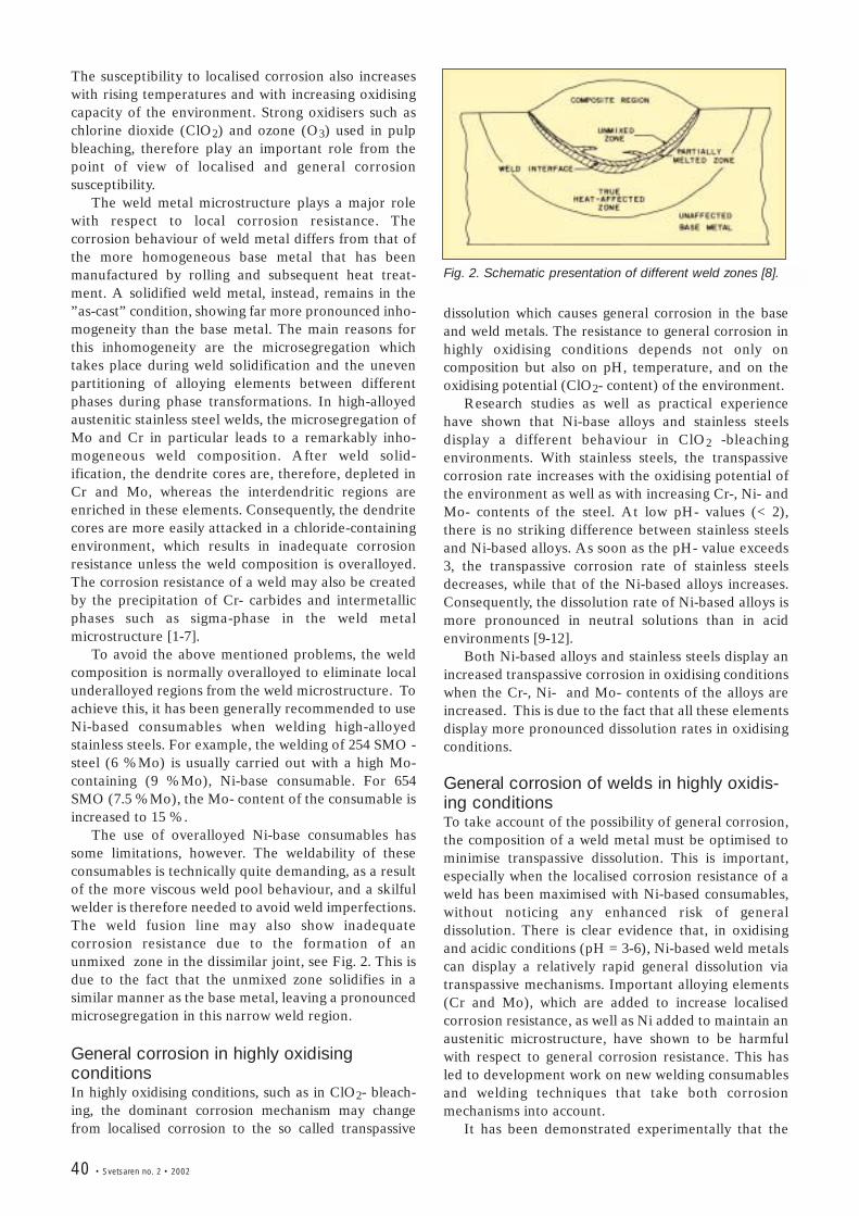
40 • Svetsaren no. 2 • 2002
The susceptibility to localised corrosion also increaseswith rising temperatures and with increasing oxidisingcapacity of the environment. Strong oxidisers such aschlorine dioxide (ClO2) and ozone (O3) used in pulpbleaching, therefore play an important role from thepoint of view of localised and general corrosionsusceptibility.
The weld metal microstructure plays a major rolewith respect to local corrosion resistance. Thecorrosion behaviour of weld metal differs from that ofthe more homogeneous base metal that has beenmanufactured by rolling and subsequent heat treat-ment. A solidified weld metal, instead, remains in the”as-cast” condition, showing far more pronounced inho-mogeneity than the base metal. The main reasons forthis inhomogeneity are the microsegregation whichtakes place during weld solidification and the unevenpartitioning of alloying elements between differentphases during phase transformations. In high-alloyedaustenitic stainless steel welds, the microsegregation ofMo and Cr in particular leads to a remarkably inho-mogeneous weld composition. After weld solid-ification, the dendrite cores are, therefore, depleted inCr and Mo, whereas the interdendritic regions areenriched in these elements. Consequently, the dendritecores are more easily attacked in a chloride-containingenvironment, which results in inadequate corrosionresistance unless the weld composition is overalloyed.The corrosion resistance of a weld may also be createdby the precipitation of Cr- carbides and intermetallicphases such as sigma-phase in the weld metalmicrostructure [1-7].
To avoid the above mentioned problems, the weldcomposition is normally overalloyed to eliminate localunderalloyed regions from the weld microstructure. Toachieve this, it has been generally recommended to useNi-based consumables when welding high-alloyedstainless steels. For example, the welding of 254 SMO -steel (6 %Mo) is usually carried out with a high Mo-containing (9 %Mo), Ni-base consumable. For 654SMO (7.5 %Mo), the Mo- content of the consumable isincreased to 15 %.
The use of overalloyed Ni-base consumables hassome limitations, however. The weldability of theseconsumables is technically quite demanding, as a resultof the more viscous weld pool behaviour, and a skilfulwelder is therefore needed to avoid weld imperfections.The weld fusion line may also show inadequatecorrosion resistance due to the formation of anunmixed zone in the dissimilar joint, see Fig. 2. This isdue to the fact that the unmixed zone solidifies in asimilar manner as the base metal, leaving a pronouncedmicrosegregation in this narrow weld region.
General corrosion in highly oxidisingconditionsIn highly oxidising conditions, such as in ClO2- bleach-ing, the dominant corrosion mechanism may changefrom localised corrosion to the so called transpassive
Fig. 2. Schematic presentation of different weld zones [8].
dissolution which causes general corrosion in the baseand weld metals. The resistance to general corrosion inhighly oxidising conditions depends not only oncomposition but also on pH, temperature, and on theoxidising potential (ClO2- content) of the environment.
Research studies as well as practical experiencehave shown that Ni-base alloys and stainless steelsdisplay a different behaviour in ClO2 -bleachingenvironments. With stainless steels, the transpassivecorrosion rate increases with the oxidising potential ofthe environment as well as with increasing Cr-, Ni- andMo- contents of the steel. At low pH- values (< 2),there is no striking difference between stainless steelsand Ni-based alloys. As soon as the pH- value exceeds3, the transpassive corrosion rate of stainless steelsdecreases, while that of the Ni-based alloys increases.Consequently, the dissolution rate of Ni-based alloys ismore pronounced in neutral solutions than in acidenvironments [9-12].
Both Ni-based alloys and stainless steels display anincreased transpassive corrosion in oxidising conditionswhen the Cr-, Ni- and Mo- contents of the alloys areincreased. This is due to the fact that all these elementsdisplay more pronounced dissolution rates in oxidisingconditions.
General corrosion of welds in highly oxidis-ing conditionsTo take account of the possibility of general corrosion,the composition of a weld metal must be optimised tominimise transpassive dissolution. This is important,especially when the localised corrosion resistance of aweld has been maximised with Ni-based consumables,without noticing any enhanced risk of generaldissolution. There is clear evidence that, in oxidisingand acidic conditions (pH = 3-6), Ni-based weld metalscan display a relatively rapid general dissolution viatranspassive mechanisms. Important alloying elements(Cr and Mo), which are added to increase localisedcorrosion resistance, as well as Ni added to maintain anaustenitic microstructure, have shown to be harmfulwith respect to general corrosion resistance. This hasled to development work on new welding consumablesand welding techniques that take both corrosionmechanisms into account.
It has been demonstrated experimentally that the
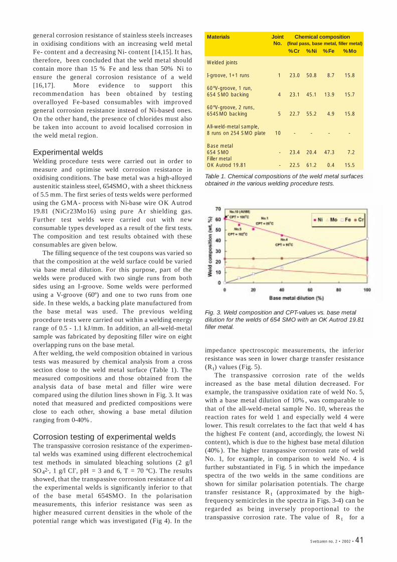
Svetsaren no. 2 • 2002 • 41
Table 1. Chemical compositions of the weld metal surfacesobtained in the various welding procedure tests.
Fig. 3. Weld composition and CPT-values vs. base metaldilution for the welds of 654 SMO with an OK Autrod 19.81filler metal.
Materials Joint Chemical compositionNo. (final pass, base metal, filler metal)
%Cr %Ni %Fe %Mo
Welded joints
I-groove, 1+1 runs 1 23.0 50.8 8.7 15.8
60ºV-groove, 1 run,654 SMO backing 4 23.1 45.1 13.9 15.7
60ºV-groove, 2 runs, 654SMO backing 5 22.7 55.2 4.9 15.8
All-weld-metal sample,8 runs on 254 SMO plate 10 - - - -
Base metal654 SMO - 23.4 20.4 47.3 7.2Filler metalOK Autrod 19.81 - 22.5 61.2 0.4 15.5
general corrosion resistance of stainless steels increasesin oxidising conditions with an increasing weld metalFe- content and a decreasing Ni- content [14,15]. It has,therefore, been concluded that the weld metal shouldcontain more than 15 % Fe and less than 50% Ni toensure the general corrosion resistance of a weld[16,17]. More evidence to support thisrecommendation has been obtained by testingoveralloyed Fe-based consumables with improvedgeneral corrosion resistance instead of Ni-based ones.On the other hand, the presence of chlorides must alsobe taken into account to avoid localised corrosion inthe weld metal region.
Experimental weldsWelding procedure tests were carried out in order tomeasure and optimise weld corrosion resistance inoxidising conditions. The base metal was a high-alloyedaustenitic stainless steel, 654SMO, with a sheet thicknessof 5.5 mm. The first series of tests welds were performedusing the GMA- process with Ni-base wire OK Autrod19.81 (NiCr23Mo16) using pure Ar shielding gas.Further test welds were carried out with newconsumable types developed as a result of the first tests.The composition and test results obtained with theseconsumables are given below.
The filling sequence of the test coupons was varied sothat the composition at the weld surface could be variedvia base metal dilution. For this purpose, part of thewelds were produced with two single runs from bothsides using an I-groove. Some welds were performedusing a V-groove (60º) and one to two runs from oneside. In these welds, a backing plate manufactured fromthe base metal was used. The previous weldingprocedure tests were carried out within a welding energyrange of 0.5 - 1.1 kJ/mm. In addition, an all-weld-metalsample was fabricated by depositing filler wire on eightoverlapping runs on the base metal. After welding, the weld composition obtained in varioustests was measured by chemical analysis from a crosssection close to the weld metal surface (Table 1). Themeasured compositions and those obtained from theanalysis data of base metal and filler wire werecompared using the dilution lines shown in Fig. 3. It wasnoted that measured and predicted compositions wereclose to each other, showing a base metal dilutionranging from 0-40%.
Corrosion testing of experimental welds The transpassive corrosion resistance of the experimen-tal welds was examined using different electrochemicaltest methods in simulated bleaching solutions (2 g/lSO42-, 1 g/l Cl-, pH = 3 and 6, T = 70 ºC). The resultsshowed, that the transpassive corrosion resistance of allthe experimental welds is significantly inferior to thatof the base metal 654SMO. In the polarisationmeasurements, this inferior resistance was seen ashigher measured current densities in the whole of thepotential range which was investigated (Fig 4). In the
impedance spectroscopic measurements, the inferiorresistance was seen in lower charge transfer resistance(Rt) values (Fig. 5).
The transpassive corrosion rate of the weldsincreased as the base metal dilution decreased. Forexample, the transpassive oxidation rate of weld No. 5,with a base metal dilution of 10%, was comparable tothat of the all-weld-metal sample No. 10, whereas thereaction rates for weld 1 and especially weld 4 werelower. This result correlates to the fact that weld 4 hasthe highest Fe content (and, accordingly, the lowest Nicontent), which is due to the highest base metal dilution(40%). The higher transpassive corrosion rate of weldNo. 1, for example, in comparison to weld No. 4 isfurther substantiated in Fig. 5 in which the impedancespectra of the two welds in the same conditions areshown for similar polarisation potentials. The chargetransfer resistance Rt (approximated by the high-frequency semicircles in the spectra in Figs. 3-4) can beregarded as being inversely proportional to thetranspassive corrosion rate. The value of Rt for a
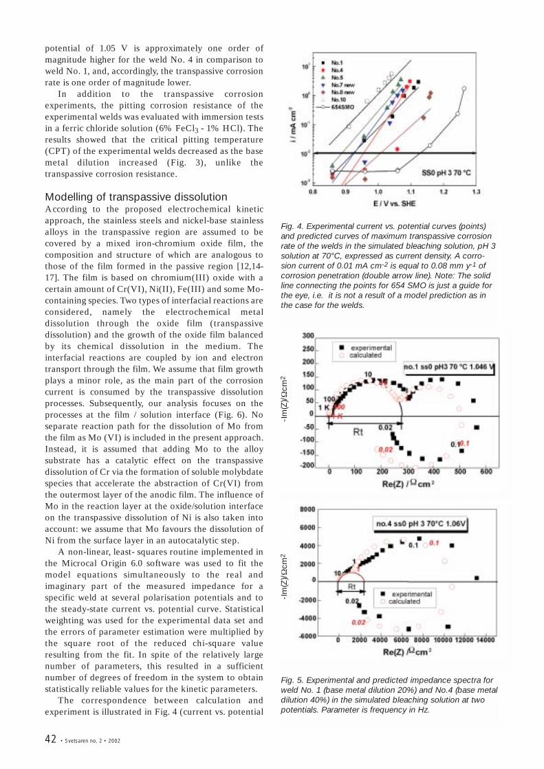
42 • Svetsaren no. 2 • 2002
Fig. 4. Experimental current vs. potential curves (points)and predicted curves of maximum transpassive corrosionrate of the welds in the simulated bleaching solution, pH 3solution at 70°C, expressed as current density. A corro-sion current of 0.01 mA cm-2 is equal to 0.08 mm y-1 ofcorrosion penetration (double arrow line). Note: The solidline connecting the points for 654 SMO is just a guide forthe eye, i.e. it is not a result of a model prediction as inthe case for the welds.
Fig. 5. Experimental and predicted impedance spectra forweld No. 1 (base metal dilution 20%) and No.4 (base metaldilution 40%) in the simulated bleaching solution at twopotentials. Parameter is frequency in Hz.
potential of 1.05 V is approximately one order ofmagnitude higher for the weld No. 4 in comparison toweld No. 1, and, accordingly, the transpassive corrosionrate is one order of magnitude lower.
In addition to the transpassive corrosionexperiments, the pitting corrosion resistance of theexperimental welds was evaluated with immersion testsin a ferric chloride solution (6% FeCl3 - 1% HCl). Theresults showed that the critical pitting temperature(CPT) of the experimental welds decreased as the basemetal dilution increased (Fig. 3), unlike thetranspassive corrosion resistance.
Modelling of transpassive dissolutionAccording to the proposed electrochemical kineticapproach, the stainless steels and nickel-base stainlessalloys in the transpassive region are assumed to becovered by a mixed iron-chromium oxide film, thecomposition and structure of which are analogous tothose of the film formed in the passive region [12,14-17]. The film is based on chromium(III) oxide with acertain amount of Cr(VI), Ni(II), Fe(III) and some Mo-containing species. Two types of interfacial reactions areconsidered, namely the electrochemical metaldissolution through the oxide film (transpassivedissolution) and the growth of the oxide film balancedby its chemical dissolution in the medium. Theinterfacial reactions are coupled by ion and electrontransport through the film. We assume that film growthplays a minor role, as the main part of the corrosioncurrent is consumed by the transpassive dissolutionprocesses. Subsequently, our analysis focuses on theprocesses at the film / solution interface (Fig. 6). Noseparate reaction path for the dissolution of Mo fromthe film as Mo (VI) is included in the present approach.Instead, it is assumed that adding Mo to the alloysubstrate has a catalytic effect on the transpassivedissolution of Cr via the formation of soluble molybdatespecies that accelerate the abstraction of Cr(VI) fromthe outermost layer of the anodic film. The influence ofMo in the reaction layer at the oxide/solution interfaceon the transpassive dissolution of Ni is also taken intoaccount: we assume that Mo favours the dissolution ofNi from the surface layer in an autocatalytic step.
A non-linear, least- squares routine implemented inthe Microcal Origin 6.0 software was used to fit themodel equations simultaneously to the real andimaginary part of the measured impedance for aspecific weld at several polarisation potentials and tothe steady-state current vs. potential curve. Statisticalweighting was used for the experimental data set andthe errors of parameter estimation were multiplied bythe square root of the reduced chi-square valueresulting from the fit. In spite of the relatively largenumber of parameters, this resulted in a sufficientnumber of degrees of freedom in the system to obtainstatistically reliable values for the kinetic parameters.
The correspondence between calculation andexperiment is illustrated in Fig. 4 (current vs. potential
-Im
(Z)/Ω
cm2
-Im
(Z)/Ω
cm2
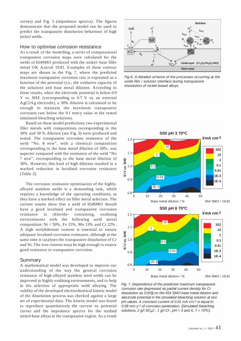
Svetsaren no. 2 • 2002 • 43
Fig.6. A detailed scheme of the processes occurring at theoxide film / solution interface during transpassivedissolution of nickel-based alloys.
Fig. 7. Dependence of the predicted maximum transpassivecorrosion rate (expressed as partial current density for Crdissolution as Cr(VI)) on the 654 SMO base metal dilution andelectrode potential in the simulated bleaching solution at twopH values. A corrosion current of 0.01 mA cm-2 is equal to0.08 mm y-1 of corrosion penetration. (Simulated bleachingsolutions, 2 g/l SO42-, 1 g/l Cl-, pH = 3 and 6, T = 70ºC).
curves) and Fig. 5 (impedance spectra). The figuresdemonstrate that the proposed model can be used topredict the transpassive dissolution behaviour of highnickel welds.
How to optimise corrosion resistanceAs a result of the modelling, a series of computationaltranspassive corrosion maps were calculated for thewelds of 654SMO produced with the nickel- base fillermetal OK Autrod 19.81. Examples of these contourmaps are shown in the Fig. 7, where the predictedmaximum transpassive corrosion rate is expressed as afunction of the potential (i.e., the oxidative capacity ofthe solution) and base metal dilution. According tothese results, when the electrode potential is below 0.9V vs. SHE (corresponding to 0.7 V vs. an externalAgCl/Ag electrode), a 30% dilution is calculated to beenough to maintain the maximum transpassivecorrosion rate below the 0.1 mm/y value in the testedsimulated bleaching solutions.
Based on these model predictions, two experimentalfiller metals with compositions corresponding to the30% and 50 % dilution (see Fig. 3) were produced andtested. The transpassive corrosion resistance of theweld ”No. 8 new”, with a chemical compositioncorresponding to the base metal dilution of 50%, wassuperior compared with the resistance of the weld “No7 new”, corresponding to the base metal dilution of30%. However, this kind of high dilution resulted in amarked reduction in localised corrosion resistance(Table 2).
The corrosion resistance optimisation of the highly-alloyed stainless welds is a demanding task, whichrequires a knowledge of the operating conditions, asthey have a marked effect on filler metal selection. Thecurrent results show that a weld of 654SMO shouldhave a good localised and transpassive corrosionresistance in chloride- containing, oxidisingenvironments with the following weld metalcomposition: Ni < 50%, Fe 15%, Mo 13% and Cr 22%.A high molybdenum content is essential to ensureadequate localised corrosion resistance, although at thesame time it catalyses the transpassive dissolution of Crand Ni. The iron content must be high enough to ensuregood resistance to transpassive corrosion.
SummaryA mathematical model was developed to improve ourunderstanding of the way the general corrosionresistance of high-alloyed stainless steel welds can beimproved in highly oxidising environments, and to helpin the selection of appropriate weld alloying. Thevalidity of the developed electrochemical kinetic modelof the dissolution process was checked against a largeset of experimental data. The kinetic model was foundto reproduce quantitatively the current vs. potentialcurves and the impedance spectra for the studiednickel-base alloys in the transpassive region. As a result
e- VCr3-
SS0 pH 3 70ºCi/mA cm-2
1E2
10
1
0.1
0.01
1E-3
1E-4
SS0 pH 6 70ºCi/mA cm-2
1E2
10
1
0.1
0.01
1E-3
1E-4
0 10 20 30 40 50
0 10 20 30 40 50
Base metal dilution / % 654 SMO / 19.81
Base metal dilution / % 654 SMO / 19.81
1.2
1.1
1.0
0.9
0.8
1.2
1.1
1.0
0.9
0.8
E/V
vs.
SH
EE
/V v
s. S
HE
10
1
0.1
0.01
1E-3
10
1
0.1
0.01
1E-3
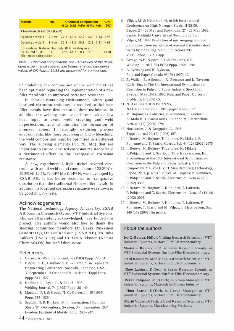
44 • Svetsaren no. 2 • 2002
Material No. Chemical composition CPT%Cr %Ni %Fe %Mo %N [ºC]
All-weld-metal samples (AWM)
Optimised weld 1 7 New 22.2 49.5 12.7 14.0 0.14 >95
Optimised weld 2 8 New 22.5 43.2 19.3 12.6 0.21 <65
Conventional Ni-base filler metal (MIG welding wire)OK Autrod 19.81 10 22.5 61.2 0.4 15.5 --- >100(filler metal composition)
Table 2. Chemical compositions and CPT-values of the devel-oped experimental covered electrodes. The correspondingvalues of OK Autrod 19.81 are presented for comparison.
of modelling, the composition of the weld metal hasbeen optimised regarding the implementation of a newfiller metal with an improved corrosion resistance.
In chloride-containing environments, where goodlocalised corrosion resistance is required, nickel-basefiller metals have demonstrated their usefulness. Inaddition, the welding must be performed with a lowheat input to avoid weld cracking and weldimperfections, and to minimise the formation ofunmixed zones. In strongly oxidising processenvironments, like those occurring in ClO2- bleaching,the weld composition must be optimised in a differentway. The alloying elements (Cr, Ni, Mo) that areimportant to ensure localised corrosion resistance havea detrimental effect on the transpassive corrosionresistance.
A new, experimental, high- nickel covered elec-trode, with an all weld metal composition of 22.2%Cr-49.5%Ni-12.7%Fe-14%Mo-0.14%N, was developed byESAB AB. It has better resistance to transpassivedissolution than the traditional Ni-base filler metals. Inaddition, its localised corrosion resistance was shown tobe good in CPT- tests.
AcknowledgementsThe National Technology Agency, Andritz Oy, ESABAB, Kemira Chemicals Oy and VTT Industrial Systems,who are all gratefully acknowledged, have funded thisproject. The authors would also like to thank thesteering committee members Dr. Erkki Pulkkinen(Andritz Oy), Dr. Leif Karlsson (ESAB AB), Mr. JuhaLukkari (ESAB Oy) and Dr. Jari Kukkonen (KemiraChemicals Oy) for useful discussions.
References 1. Garner, A. Welding Journal, 62 (1983) Pppp. 27 - 34. 2. Hibner, E. L., Hinshaw E. B. & Lamb, S. in Tappi 1991
Engineering Conference, Nashville, Tennesee, USA, 30 September - 3 October 1991. Atlanta: Tappi Press.Pppp. 511 - 527.
3. Karlsson, L., Ryen, L. & Pak, S. 1995. Welding Journal, 74 (1995) Pppp. 28 - 40.
4. Marshall, P. I. & Gooch, T. G. Corrosion, 49 (1993)Pppp. 514 - 526.
5. Suutala, N. & Kurkela, M. in International StainlessSteels ‘84, Gothenburg, Sweden, 3 - 4 September 1984.London: Institute of Metals. Pppp. 240 - 247.
6. Vilpas, M. & Hänninen, H. in 5th InternationalConference on High Nitrogen Steels, HNS-98. Espoo, 24 - 26 May and Stockholm, 27 - 28 May 1998.Espoo: Helsinki University of Technology. 6 p.
7. Vilpas, M. 1999. Prediction of microsegregation andpitting corrosion resistance of austenitic stainless steelwelds by modelling. VTT Publications 390, VTT, Espoo, 139p + app.
8. Savage, W.F., Nippes, E.F. & Szekeres, E.S. Welding Journal, 55 (1976) Pppp. 260s - 268s.
9. A. Wensley and H. Dykstra, Pulp and Paper Canada 98 (9) (1997) 40.
10. B. Wallen, E. Alfonsson, A. Brorsson and L. Tuveson-Carlström, in The 8th International Symposium onCorrosion in Pulp and Paper Industry, Stockholm,Sweden, May 16-19, 1995, Pulp and Paper CorrosionProblems, 8 (1995) 65.
11. N. Arlt, in CORROSION’95, NACE International, 1995, paper Nono. 577.
12. M. Bojinov, G. Fabricius, P. Kinnunen, T. Laitinen, K. Mäkelä, T. Saario and G. Sundholm, Electrochim.Acta 45 (17) (2000) 2791.
13. Nordström, J. & Bergquist, A. 1996. Tappi Journal 79, (2) (1996) 187.
14. I. Betova, M. Bojinov, T. Laitinen, K. Mäkelä, P.Pohjanne and T. Saario, Corros. Sci. 44 (12) (2002) 2675
15. I. Betova, M. Bojinov, T. Laitinen, K. Mäkelä, P. Pohjanne and T. Saario, in Tero Hakkarainen, Ed.,Proceedings of the 10th International Symposium onCorrosion in the Pulp and Paper Industry, VTTSymposium 214, Vol.1, VTT Manufacturing Technology,Espoo, 2001, p.323; I. Betova, M. Bojinov, P. Kinnunen,P. Pohjanne and T. Saario, Electrochim. Acta 47 (20)(2002) 3335
16. I. Betova, M. Bojinov, P. Kinnunen, T. Laitinen, P. Pohjanne and T. Saario, Electrochim. Acta, 47 (13-14)(2002) 2093.
17. I. Betova, M. Bojinov, P. Kinnunen, T. Laitinen, P.Pohjanne, T. Saario and M. Vilpas, J. Electrochem. Soc.149 (11) (2002) (in print).
About the authors
Iva G. Betova, PhD, is Visiting Research Scientist at VTTIndustrial Systems, Surface Film Electrochemistry.
Martin S. Bojinov, PhD, is Senior Research Scientist atVTT Industrial Systems, Surface Film Electrochemistry.
Petri Kinnunen, MSc (Eng), is Research Scientist at VTTIndustrial Systems, Surface Film Electrochemistry.
Timo Laitinen, DrTech, is Senior Research Scientist atVTT Industrial Systems, Surface Film Electrochemistry.
Pekka Pohjanne, MSc(Tech), is Group Manager at VTTIndustrial Systems, Materials in Process Industry.
Timo Saario, DrTech, is Group Manager at VTTIndustrial Systems, Surface Film Electrochemistry.
Martti Vilpas, DrTech, is Chief Research Scientist at VTTIndustrial Systems, Manufacturing Methods.
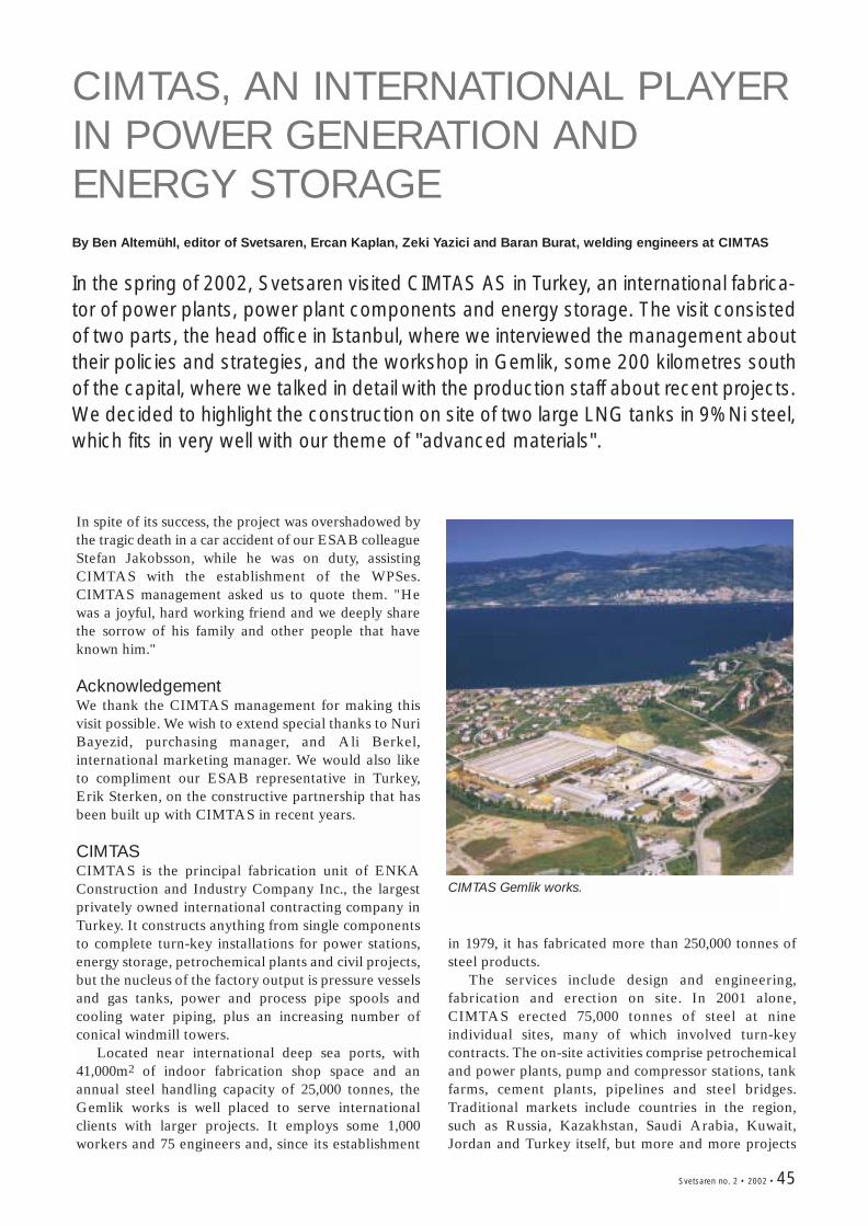
Svetsaren no. 2 • 2002 • 45
CIMTAS, AN INTERNATIONAL PLAYERIN POWER GENERATION ANDENERGY STORAGEBy Ben Altemühl, editor of Svetsaren, Ercan Kaplan, Zeki Yazici and Baran Burat, welding engineers at CIMTAS
In the spring of 2002, Svetsaren visited CIMTAS AS in Turkey, an international fabrica-tor of power plants, power plant components and energy storage. The visit consistedof two parts, the head office in Istanbul, where we interviewed the management abouttheir policies and strategies, and the workshop in Gemlik, some 200 kilometres southof the capital, where we talked in detail with the production staff about recent projects.We decided to highlight the construction on site of two large LNG tanks in 9%Ni steel,which fits in very well with our theme of "advanced materials".
In spite of its success, the project was overshadowed bythe tragic death in a car accident of our ESAB colleagueStefan Jakobsson, while he was on duty, assistingCIMTAS with the establishment of the WPSes.CIMTAS management asked us to quote them. "Hewas a joyful, hard working friend and we deeply sharethe sorrow of his family and other people that haveknown him."
AcknowledgementWe thank the CIMTAS management for making thisvisit possible. We wish to extend special thanks to NuriBayezid, purchasing manager, and Ali Berkel,international marketing manager. We would also liketo compliment our ESAB representative in Turkey,Erik Sterken, on the constructive partnership that hasbeen built up with CIMTAS in recent years.
CIMTASCIMTAS is the principal fabrication unit of ENKAConstruction and Industry Company Inc., the largestprivately owned international contracting company inTurkey. It constructs anything from single componentsto complete turn-key installations for power stations,energy storage, petrochemical plants and civil projects,but the nucleus of the factory output is pressure vesselsand gas tanks, power and process pipe spools andcooling water piping, plus an increasing number ofconical windmill towers.
Located near international deep sea ports, with41,000m2 of indoor fabrication shop space and anannual steel handling capacity of 25,000 tonnes, theGemlik works is well placed to serve internationalclients with larger projects. It employs some 1,000workers and 75 engineers and, since its establishment
CIMTAS Gemlik works.
in 1979, it has fabricated more than 250,000 tonnes ofsteel products.
The services include design and engineering,fabrication and erection on site. In 2001 alone,CIMTAS erected 75,000 tonnes of steel at nineindividual sites, many of which involved turn-keycontracts. The on-site activities comprise petrochemicaland power plants, pump and compressor stations, tankfarms, cement plants, pipelines and steel bridges.Traditional markets include countries in the region,such as Russia, Kazakhstan, Saudi Arabia, Kuwait,Jordan and Turkey itself, but more and more projects
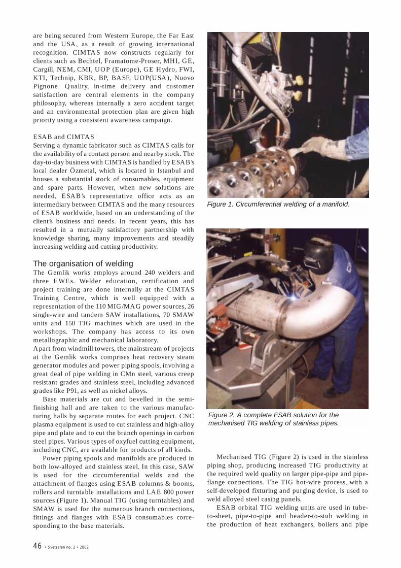
46 • Svetsaren no. 2 • 2002
are being secured from Western Europe, the Far Eastand the USA, as a result of growing internationalrecognition. CIMTAS now constructs regularly forclients such as Bechtel, Framatome-Proser, MHI, GE,Cargill, NEM, CMI, UOP (Europe), GE Hydro, FWI,KTI, Technip, KBR, BP, BASF, UOP(USA), NuovoPignone. Quality, in-time delivery and customersatisfaction are central elements in the companyphilosophy, whereas internally a zero accident targetand an environmental protection plan are given highpriority using a consistent awareness campaign.
ESAB and CIMTASServing a dynamic fabricator such as CIMTAS calls forthe availability of a contact person and nearby stock. Theday-to-day business with CIMTAS is handled by ESAB’slocal dealer Özmetal, which is located in Istanbul andhouses a substantial stock of consumables, equipmentand spare parts. However, when new solutions areneeded, ESAB’s representative office acts as anintermediary between CIMTAS and the many resourcesof ESAB worldwide, based on an understanding of theclient’s business and needs. In recent years, this hasresulted in a mutually satisfactory partnership withknowledge sharing, many improvements and steadilyincreasing welding and cutting productivity.
The organisation of weldingThe Gemlik works employs around 240 welders andthree EWEs. Welder education, certification andproject training are done internally at the CIMTASTraining Centre, which is well equipped with arepresentation of the 110 MIG/MAG power sources, 26single-wire and tandem SAW installations, 70 SMAWunits and 150 TIG machines which are used in theworkshops. The company has access to its ownmetallographic and mechanical laboratory. Apart from windmill towers, the mainstream of projectsat the Gemlik works comprises heat recovery steamgenerator modules and power piping spools, involving agreat deal of pipe welding in CMn steel, various creepresistant grades and stainless steel, including advancedgrades like P91, as well as nickel alloys.
Base materials are cut and bevelled in the semi-finishing hall and are taken to the various manufac-turing halls by separate routes for each project. CNCplasma equipment is used to cut stainless and high-alloypipe and plate and to cut the branch openings in carbonsteel pipes. Various types of oxyfuel cutting equipment,including CNC, are available for products of all kinds.
Power piping spools and manifolds are produced inboth low-alloyed and stainless steel. In this case, SAWis used for the circumferential welds and theattachment of flanges using ESAB columns & booms,rollers and turntable installations and LAE 800 powersources (Figure 1). Manual TIG (using turntables) andSMAW is used for the numerous branch connections,fittings and flanges with ESAB consumables corre-sponding to the base materials.
Mechanised TIG (Figure 2) is used in the stainlesspiping shop, producing increased TIG productivity atthe required weld quality on larger pipe-pipe and pipe-flange connections. The TIG hot-wire process, with aself-developed fixturing and purging device, is used toweld alloyed steel casing panels.
ESAB orbital TIG welding units are used in tube-to-sheet, pipe-to-pipe and header-to-stub welding inthe production of heat exchangers, boilers and pipe
Figure 1. Circumferential welding of a manifold.
Figure 2. A complete ESAB solution for themechanised TIG welding of stainless pipes.
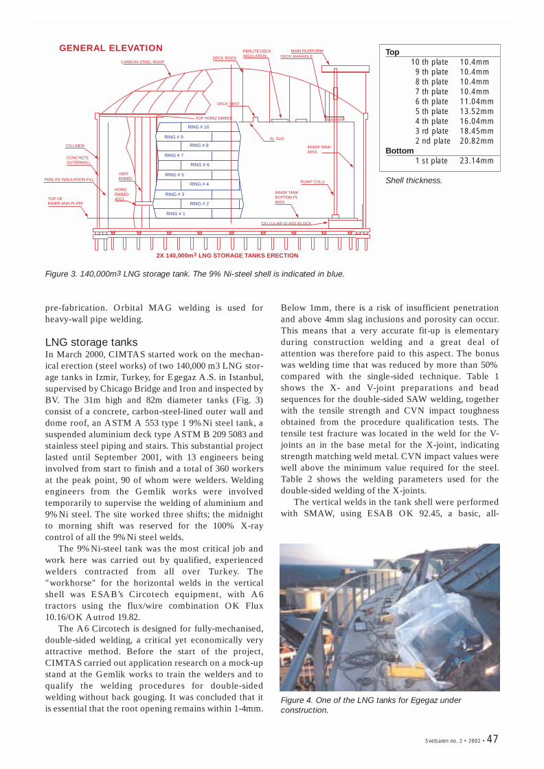
Svetsaren no. 2 • 2002 • 47
pre-fabrication. Orbital MAG welding is used forheavy-wall pipe welding.
LNG storage tanksIn March 2000, CIMTAS started work on the mechan-ical erection (steel works) of two 140,000 m3 LNG stor-age tanks in Izmir, Turkey, for Egegaz A.S. in Istanbul,supervised by Chicago Bridge and Iron and inspected byBV. The 31m high and 82m diameter tanks (Fig. 3)consist of a concrete, carbon-steel-lined outer wall anddome roof, an ASTM A 553 type 1 9%Ni steel tank, asuspended aluminium deck type ASTM B 209 5083 andstainless steel piping and stairs. This substantial projectlasted until September 2001, with 13 engineers beinginvolved from start to finish and a total of 360 workersat the peak point, 90 of whom were welders. Weldingengineers from the Gemlik works were involvedtemporarily to supervise the welding of aluminium and9%Ni steel. The site worked three shifts; the midnightto morning shift was reserved for the 100% X-raycontrol of all the 9%Ni steel welds.
The 9%Ni-steel tank was the most critical job andwork here was carried out by qualified, experiencedwelders contracted from all over Turkey. The"workhorse" for the horizontal welds in the verticalshell was ESAB’s Circotech equipment, with A6tractors using the flux/wire combination OK Flux10.16/OK Autrod 19.82.
The A6 Circotech is designed for fully-mechanised,double-sided welding, a critical yet economically veryattractive method. Before the start of the project,CIMTAS carried out application research on a mock-upstand at the Gemlik works to train the welders and toqualify the welding procedures for double-sidedwelding without back gouging. It was concluded that itis essential that the root opening remains within 1-4mm.
Below 1mm, there is a risk of insufficient penetrationand above 4mm slag inclusions and porosity can occur.This means that a very accurate fit-up is elementaryduring construction welding and a great deal ofattention was therefore paid to this aspect. The bonuswas welding time that was reduced by more than 50%compared with the single-sided technique. Table 1shows the X- and V-joint preparations and beadsequences for the double-sided SAW welding, togetherwith the tensile strength and CVN impact toughnessobtained from the procedure qualification tests. Thetensile test fracture was located in the weld for the V-joints an in the base metal for the X-joint, indicatingstrength matching weld metal. CVN impact values werewell above the minimum value required for the steel.Table 2 shows the welding parameters used for thedouble-sided welding of the X-joints.
The vertical welds in the tank shell were performedwith SMAW, using ESAB OK 92.45, a basic, all-
GENERAL ELEVATION
2X 140,000m LNG STORAGE TANKS ERECTION3
RING # 10
RING # 9
RING # 8
RING # 7
RING # 6
RING # 5
RING # 4
RING # 3
RING # 2
RING # 1
CARBON STEEL ROOFDECK RODS
PERLITE DECK INSULATION
MAIN PLATFORMDECK MANHOLE
CONCRETEOUTERWALL
INNER TANKBOTTOM PLA553
PUMP COLU
CELLULAR GLASS BLOCK
CS LINER INNER TANKA553
AL SUS
PERLITE INSULATION FILL
DECK VENT
TOP HORIZ EMBED
TOP OFINNER ANN PLATE
VERTENBED
HORIZEMBEDA553
Figure 3. 140,000m3 LNG storage tank. The 9% Ni-steel shell is indicated in blue.
Figure 4. One of the LNG tanks for Egegaz underconstruction.
Top10 th plate 10.4mm9 th plate 10.4mm8 th plate 10.4mm7 th plate 10.4mm6 th plate 11.04mm5 th plate 13.52mm4 th plate 16.04mm3 rd plate 18.45mm2 nd plate 20.82mm
Bottom1 st plate 23.14mm
Shell thickness.
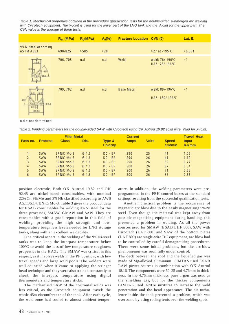
48 • Svetsaren no. 2 • 2002
position electrode. Both OK Autrod 19.82 and OK92.45 are nickel-based consumables, with nominal22%Cr, 9%Mo and 3%Nb classified according to AWSA5.11/5.14: ENiCrMo-3. Table 3 gives the product datafor ESAB consumables for welding 9%Ni steel for thethree processes, SMAW, GMAW and SAW. They areconsumables with a good reputation in this field ofwelding, providing the high strength and low-temperature toughness levels needed for LNG storagetanks, along with an excellent weldability.
One critical aspect in the welding of the 9%Ni-steeltanks was to keep the interpass temperature below100°C to avoid the loss of low-temperature toughnessproperties in the HAZ. The SMAW was critical in thisrespect, as it involves welds in the PF position, with lowtravel speeds and large weld pools. The welders werewell educated when it came to applying the stringerbead technique and they were also trained constantly tocheck the interpass temperature using digitalthermometers and temperature sticks.
The mechanised SAW of the horizontal welds wasless critical, as the Circotech equipment travels thewhole 45m circumference of the tank. After each cycle,the weld zone had cooled to almost ambient temper-
Table 1. Mechanical properties obtained in the procedure qualification tests for the double-sided submerged arc weldingwith Circotech equipment. The X-joint is used for the lower part of the LNG tank and the V-joint for the upper part. TheCVN value is the average of three tests.
Rm (MPa) Rp(MPa) A5(%) Fracture Location CVN (J) Lat. E.
9%Ni steel accordingASTM A553 690-825 >585 >20 >27 at -195ºC >0.381
706, 705 n.d n.d Weld weld: 76/-196ºC >1HAZ: 78/-196ºC
709, 702 n.d n.d Base Metal weld: 89/-196ºC >1
HAZ: 180/-196ºC
n.d.= not determined
ature. In addition, the welding parameters were pre-programmed in the PEH control boxes at the standardsettings resulting from the successful qualification tests.
Another practical problem is the occurrence ofmagnetic arc blow due to the easily magnetising 9%Nisteel. Even though the material was kept away frompossible magnetising equipment during handling, thispresented a problem in welding. As all the powersources used for SMAW (ESAB LHF 800), SAW withCircotech (LAF 800) and SAW of the bottom plates(LAF 800) are single-wire DC equipment, arc blow hadto be controlled by careful demagnetising procedures.There were some initial problems, but the arc-blowphenomenon was soon fully under control.The deck between the roof and the liquefied gas wasmade of Mg-alloyed aluminium. CIMTAS used ESABLAW power sources in combination with OK Autrod18.16. The components were 50, 25 and 4.76mm in thick-ness. In the 4.76mm thickness, pure argon was used asthe shielding gas, but for the thicker componentsCIMTAS used Ar/He mixtures to increase the weldpenetration and the bead appearance. The air turbu-lence inside the tank presented a problem, which wasovercome by using rolling tents over the welding spots.
Filler Metal Current Travel HeatPass no. Process Class Dia. Type & Amps Volts Speed Input
Polarity cm/min KJ/mm
1 SAW ERNiCrMo-3 Ø 1.6 DC - EP 290 25 41 1.062 SAW ERNiCrMo-3 Ø 1.6 DC - EP 290 26 41 1.103 SAW ERNiCrMo-3 Ø 1.6 DC - EP 290 26 59 0.774 SAW ERNiCrMo-3 Ø 1.6 DC - EP 300 26 87 0.545 SAW ERNiCrMo-3 Ø 1.6 DC - EP 300 26 71 0.666 SAW ERNiCrMo-3 Ø 1.6 DC - EP 300 26 83 0.56
Table 2. Welding parameters for the double-sided SAW with Circotech using OK Autrod 19.82 solid wire. Valid for X-joint.
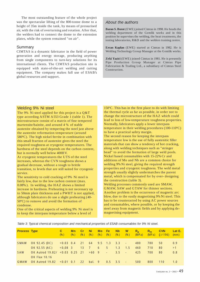
Svetsaren no. 2 • 2002 • 49
Welding 9% Ni steelThe 9% Ni steel applied for this project is a Q&Ttype according ASTM A553 Grade 1 (table 1). Themicrostructure consist of a matrix of fine temperedmartensite/bainite, and around 4 % of stableaustenite obtained by tempering the steel just abovethe austenite reformation temperature (around580ºC). The high nickel ferrite in combination withthis small fraction of austenite gives the steel therequired toughness at cryogenic temperatures. Thehardness of the steel depends on the carbon content,but is normally well below 400HV. At cryogenic temperatures the UTS of the steelincreases, whereas the CVN toughness shows agradual decrease, without a tough to brittletransition, to levels that are still suited for cryogenicservice.The sensitivity to cold cracking of 9% Ni steel isfairly low, due to the low carbon content (max.0.08%). In welding, the HAZ shows a limitedincrease in hardness. Preheating is not necessary upto 50mm plate thickness and a PWHT is not applied,although fabricators do use a slight preheating (40-50ºC) to remove and avoid the formation ofcondense. One of the critical aspects of welding 9% Ni steel isto keep the interpass temperature below a level of
150ºC. This has in the first place to do with limitingthe thermal cycle as far as possible, in order not tochange the microstructure of the HAZ which couldlead to loss of low-temperature toughness properties.Normally, fabricators apply a lower interpasstemperature in their welding procedures (100-110ºC)to have a practical safety margin.The second reason for keeping the interpasstemperature low is the use of fully austenitic fillermaterials that can show a tendency of hot cracking,along with welding techniques such as "stringerbead" to avoid the formation of large weld pools.Nickel based consumables with 15-22%Cr andadditions of Mo and Nb are a common choice forwelding 9%Ni steel, giving the required strengthproperties and cryogenic toughness. The weld metalstrength usually slightly undermatches the parentmetal, which is compensated for by over- designingthe construction (table 3). Welding processes commonly used are SMAW,GMAW, SAW and GTAW for thinner sections. Another problem is the occurrence of magnetic arcblow, due to the easily magnetising 9%Ni steel. Thishas to be counteracted by using AC power sourcesand consumables, where possible, or by keeping thesteel away from magnetic fields and by applying de-magnetising equipment.
The most outstanding feature of the whole projectwas the spectacular lifting of the 800-tonne dome to aheight of 35m inside the tank, by means of pressurisedair, with the risk of overturning and rotation. After that,the welders had to connect the dome to the extensionplates, while the system remained "on air".
SummaryCIMTAS is a dynamic fabricator in the field of powergeneration and energy storage, producing anythingfrom single components to turn-key solutions for itsinternational clients. The CIMTAS production site isequipped with state-of-the-art welding and cuttingequipment. The company makes full use of ESAB’sglobal resources and support.
Table 3: Typical chemical composition and mechanical properties of ESAB consumables for 9% Ni steel.
Process Type C Mn Cr Ni Mo Fe Nb W Rp Rm CVN Lat E.(%) (%) (%) (%) (%) (%) (%) (%) (MPa) (MPa) (J/-196) (mm)
SMAW OK 92.45 (DC) <0.03 0.4 21 64 9.5 1.3 3.3 - 480 780 50 0.9
OK 92.55 (AC) <0,08 3 13 7 6 5 1.3 1.5 460 710 80 >1
SAW OK Autrod 19.82/ <0.03 0.25 21 >60 9 - 3.5 - 425 700 80 0.8
OK Flux 10.16
GMAW OK Autrod 19.82 <0.01 0.1 22 bal. 9 0.5 3.5 - 500 800 110 1.0
About the authors
Baran S. Burat (EWE) joined Cimtas in 1998. He heads thewelding department of the Gemlik works and in thisposition he supervises the welding, the heat treatments, thetesting laboratories, R&D and the welders training centre.
Ercan Kaplan (EWE) started at Cimtas in 1982. He isWelding Technology Group Manager at the Gemlik works.
Zeki Yazici (EWE) joined Cimtas in 1981. He is presentlyPipe Production Group Manager at Cimtas PipeFabrication & Trading Ltd., a subsidiary of Cimtas SteelConstruction.
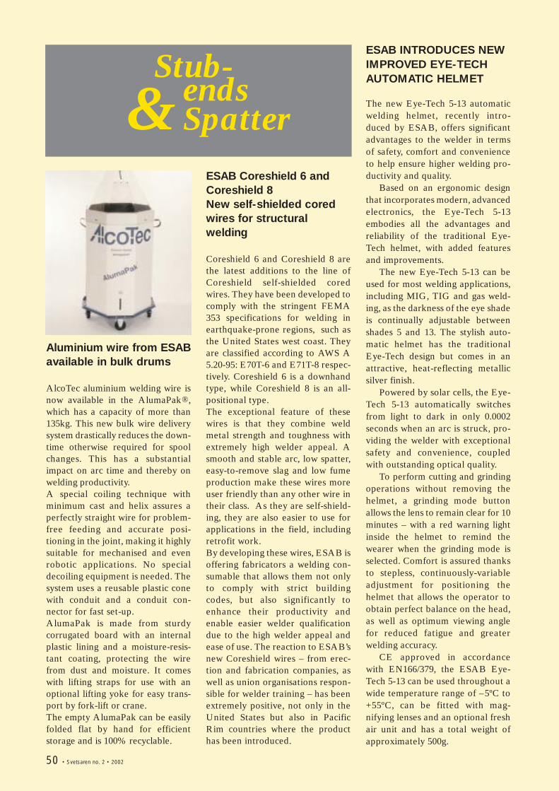
Stub-ends Spatter&
Aluminium wire from ESABavailable in bulk drums
AlcoTec aluminium welding wire isnow available in the AlumaPak®,which has a capacity of more than135kg. This new bulk wire deliverysystem drastically reduces the down-time otherwise required for spoolchanges. This has a substantialimpact on arc time and thereby onwelding productivity.A special coiling technique withminimum cast and helix assures aperfectly straight wire for problem-free feeding and accurate posi-tioning in the joint, making it highlysuitable for mechanised and evenrobotic applications. No specialdecoiling equipment is needed. Thesystem uses a reusable plastic conewith conduit and a conduit con-nector for fast set-up.AlumaPak is made from sturdycorrugated board with an internalplastic lining and a moisture-resis-tant coating, protecting the wirefrom dust and moisture. It comeswith lifting straps for use with anoptional lifting yoke for easy trans-port by fork-lift or crane.The empty AlumaPak can be easilyfolded flat by hand for efficientstorage and is 100% recyclable.
ESAB Coreshield 6 andCoreshield 8New self-shielded coredwires for structuralwelding
Coreshield 6 and Coreshield 8 arethe latest additions to the line ofCoreshield self-shielded coredwires. They have been developed tocomply with the stringent FEMA353 specifications for welding inearthquake-prone regions, such asthe United States west coast. Theyare classified according to AWS A5.20-95: E70T-6 and E71T-8 respec-tively. Coreshield 6 is a downhandtype, while Coreshield 8 is an all-positional type.The exceptional feature of thesewires is that they combine weldmetal strength and toughness withextremely high welder appeal. Asmooth and stable arc, low spatter,easy-to-remove slag and low fumeproduction make these wires moreuser friendly than any other wire intheir class. As they are self-shield-ing, they are also easier to use forapplications in the field, includingretrofit work.By developing these wires, ESAB isoffering fabricators a welding con-sumable that allows them not onlyto comply with strict buildingcodes, but also significantly toenhance their productivity andenable easier welder qualificationdue to the high welder appeal andease of use. The reaction to ESAB’snew Coreshield wires – from erec-tion and fabrication companies, aswell as union organisations respon-sible for welder training – has beenextremely positive, not only in theUnited States but also in PacificRim countries where the producthas been introduced.
ESAB INTRODUCES NEWIMPROVED EYE-TECHAUTOMATIC HELMET
The new Eye-Tech 5-13 automaticwelding helmet, recently intro-duced by ESAB, offers significantadvantages to the welder in termsof safety, comfort and convenienceto help ensure higher welding pro-ductivity and quality.
Based on an ergonomic designthat incorporates modern, advancedelectronics, the Eye-Tech 5-13embodies all the advantages andreliability of the traditional Eye-Tech helmet, with added featuresand improvements.
The new Eye-Tech 5-13 can beused for most welding applications,including MIG, TIG and gas weld-ing, as the darkness of the eye shadeis continually adjustable betweenshades 5 and 13. The stylish auto-matic helmet has the traditionalEye-Tech design but comes in anattractive, heat-reflecting metallicsilver finish.
Powered by solar cells, the Eye-Tech 5-13 automatically switchesfrom light to dark in only 0.0002seconds when an arc is struck, pro-viding the welder with exceptionalsafety and convenience, coupledwith outstanding optical quality.
To perform cutting and grindingoperations without removing thehelmet, a grinding mode buttonallows the lens to remain clear for 10minutes – with a red warning lightinside the helmet to remind thewearer when the grinding mode isselected. Comfort is assured thanksto stepless, continuously-variableadjustment for positioning thehelmet that allows the operator toobtain perfect balance on the head,as well as optimum viewing anglefor reduced fatigue and greaterwelding accuracy.
CE approved in accordancewith EN166/379, the ESAB Eye-Tech 5-13 can be used throughout awide temperature range of –5ºC to+55ºC, can be fitted with mag-nifying lenses and an optional freshair unit and has a total weight ofapproximately 500g.
50 • Svetsaren no. 2 • 2002
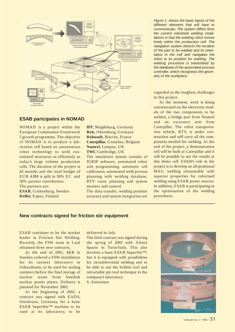
NOMAD is a project within theEuropean Commission Framework5 growth programme. The objectiveof NOMAD is to produce a fab-rication cell based on autonomousrobot technology to weld cus-tomised structures as efficiently astoday’s large volume productioncells. The duration of the project is42 months and the total budget ofEUR 4.8M is split in 50% EC and50% partner contribution.The partners are:ESAB, Gothenburg, SwedenDelfoi, Espoo, Finland
IFF, Magdeburg, GermanyReis, Obernburg, GermanyRobosoft, Biarritz, FranceCaterpillar, Gosselies, BelgiumNusteel, Lympne, UKTWI, Cambridge, UKThe simulation system consists ofIGRIP software, automated robotarm programming, automatic cellcalibration, automated weld processplanning with welding database,RTV route planning and systemmonitor and control.The data transfer, welding positionaccuracy and system integration are
regarded as the toughest challengesin this project.
At the moment, work is beingconcentrated on the electronic mod-els of the two components to bewelded, a bridge part from Nusteeland an excavator arm fromCaterpillar. The robot transporta-tion vehicle, RTV, is under con-struction and will carry all the com-ponents needed for welding. At theend of the project, a demonstrationcell will be built at Caterpillar and itwill be possible to see the results atthis demo cell. ESAB’s role in theproject is to develop an all-positionalMAG welding consumable withsuperior properties for robotisedwelding using ESAB power sources.In addition, ESAB is participating inthe optimisation of the weldingprocedures.
Figure 1. shows the basic layout of thedifferent elements that will have tocommunicate. The system differs fromthe current robotised welding instal-lations in that the welding robot movesfreely within the production cell. Thenavigation system detects the locationof the part to be welded and its orien-tation in the cell and navigates therobot to its position for welding. Thewelding procedure is transmitted bythe database of the automated processcontroller, which recognises the geom-etry of the workpiece.
ESAB partcipates in NOMAD
Svetsaren no. 2 • 2002 • 51
ESAB continues to be the marketleader in Friction Stir Welding.Recently, the FSW team in Laxåobtained three new contracts.
At the end of 2001, SKB inSweden ordered a FSW installationfor its canister laboratory inOskarshamn, to be used for sealingcanisters before the final storage ofnuclear waste from Swedishnuclear power plants. Delivery isplanned for November 2002.
At the beginning of 2002, acontract was signed with EADS,Ottobrunn, Germany, for a basicESAB SuperStir™ machine to beused at its laboratory, to be
delivered in July.The third contract was signed duringthe spring of 2002 with AleniaSpazio in Turin/Italy. This alsoinvolves a basic ESAB SuperStir™,but it is equipped with possibilitiesfor circumferential welding and tobe able to use the bobbin tool andretractable pin tool technique in thecompany’s laboratory.S. Antonsson
New contracts signed for friction stir equipment
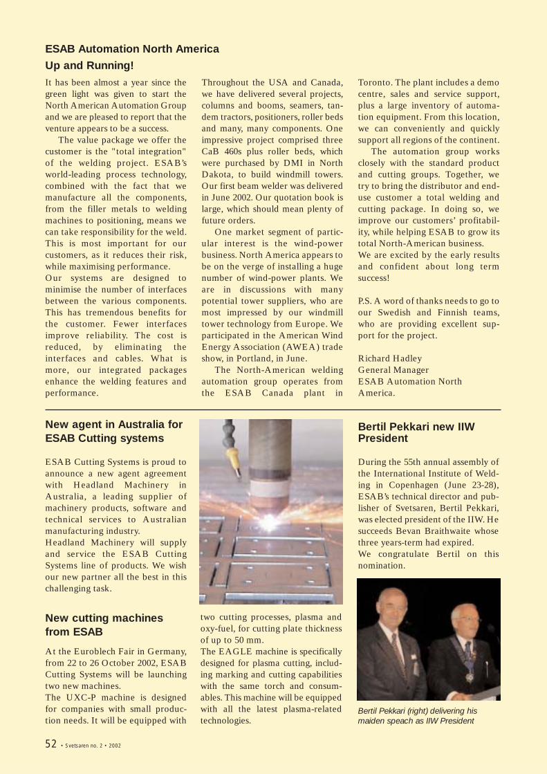
It has been almost a year since thegreen light was given to start theNorth American Automation Groupand we are pleased to report that theventure appears to be a success.
The value package we offer thecustomer is the "total integration"of the welding project. ESAB’sworld-leading process technology,combined with the fact that wemanufacture all the components,from the filler metals to weldingmachines to positioning, means wecan take responsibility for the weld.This is most important for ourcustomers, as it reduces their risk,while maximising performance.Our systems are designed tominimise the number of interfacesbetween the various components.This has tremendous benefits forthe customer. Fewer interfacesimprove reliability. The cost isreduced, by eliminating theinterfaces and cables. What ismore, our integrated packagesenhance the welding features andperformance.
Throughout the USA and Canada,we have delivered several projects,columns and booms, seamers, tan-dem tractors, positioners, roller bedsand many, many components. Oneimpressive project comprised threeCaB 460s plus roller beds, whichwere purchased by DMI in NorthDakota, to build windmill towers.Our first beam welder was deliveredin June 2002. Our quotation book islarge, which should mean plenty offuture orders.
One market segment of partic-ular interest is the wind-powerbusiness. North America appears tobe on the verge of installing a hugenumber of wind-power plants. Weare in discussions with manypotential tower suppliers, who aremost impressed by our windmilltower technology from Europe. Weparticipated in the American WindEnergy Association (AWEA) tradeshow, in Portland, in June.
The North-American weldingautomation group operates fromthe ESAB Canada plant in
Toronto. The plant includes a democentre, sales and service support,plus a large inventory of automa-tion equipment. From this location,we can conveniently and quicklysupport all regions of the continent.
The automation group worksclosely with the standard productand cutting groups. Together, wetry to bring the distributor and end-use customer a total welding andcutting package. In doing so, weimprove our customers’ profitabil-ity, while helping ESAB to grow itstotal North-American business. We are excited by the early resultsand confident about long termsuccess!
P.S. A word of thanks needs to go toour Swedish and Finnish teams,who are providing excellent sup-port for the project.
Richard HadleyGeneral ManagerESAB Automation NorthAmerica.
ESAB Automation North America
Up and Running!
52 • Svetsaren no. 2 • 2002
New agent in Australia forESAB Cutting systems
ESAB Cutting Systems is proud toannounce a new agent agreementwith Headland Machinery inAustralia, a leading supplier ofmachinery products, software andtechnical services to Australianmanufacturing industry.Headland Machinery will supplyand service the ESAB CuttingSystems line of products. We wishour new partner all the best in thischallenging task.
Bertil Pekkari new IIWPresident
During the 55th annual assembly ofthe International Institute of Weld-ing in Copenhagen (June 23-28),ESAB’s technical director and pub-lisher of Svetsaren, Bertil Pekkari,was elected president of the IIW. Hesucceeds Bevan Braithwaite whosethree years-term had expired. We congratulate Bertil on thisnomination.
two cutting processes, plasma andoxy-fuel, for cutting plate thicknessof up to 50 mm.The EAGLE machine is specificallydesigned for plasma cutting, includ-ing marking and cutting capabilitieswith the same torch and consum-ables. This machine will be equippedwith all the latest plasma-relatedtechnologies.
New cutting machinesfrom ESAB
At the Euroblech Fair in Germany,from 22 to 26 October 2002, ESABCutting Systems will be launchingtwo new machines.The UXC-P machine is designedfor companies with small produc-tion needs. It will be equipped with
Bertil Pekkari (right) delivering hismaiden speach as IIW President
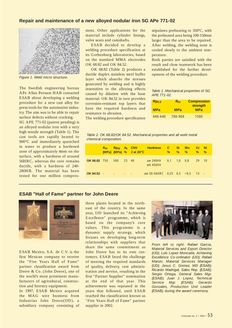
The Swedish engineering bureauAPe Allan Persson HAB contactedESAB about developing a weldingprocedure for a new cast alloy forpress tools for the automotive indus-try. The aim was to be able to repairsurface defects without cracking.SG APE 771-02 (patent pending) isan alloyed nodular iron with a veryhigh tensile strength (Table 1). Thecast tools are rapidly heated to900°C and immediately quenchedin water to produce a hardenedzone of approximately 4mm on thesurface, with a hardness of around56HRC, whereas the core remainsductile, with a hardness of 240-280HB. The material has beentested for one million compres-
stipulates preheating to 350ºC, withthe preheated area being 100-150mmlarger than the area to be repaired.After welding, the welding zone iscooled slowly to the ambient tem-perature.Both parties are satisfied with theresult and close teamwork has beenestablished for the further devel-opment of the welding procedure.
Figure 1. Weld micro structure.
Repair and maintenance of a new alloyed nodular iron SG APe 771-02
sions. Other applications for thematerial include cylinder linings,valve seats and camshafts.
ESAB decided to develop awelding procedure specification atits Gothenburg laboratories, basedon the standard MMA electrodesOK 68.82 and OK 84.52.
OK 68.82 (Table 2) produces aductile duplex stainless steel bufferlayer which absorbs the stressesgenerated by welding and is highlyinsensitive to the alloying effectscaused by dilution with the basematerial. OK 84.52 in turn providescorrosion-resistant top layers thathave the required hardness andresistance to abrasion.The welding procedure specification
Table 2. OK 68.82/OK 84.52. Mechanical properties and all weld metal chemical composition.
Rm Rp02 A5 CNV Hardness C Si Mn Cr Ni(MPa) (MPa) % J at 20°C % % % % %
OK 68.82 750 500 23 40 aw 240HV 0,1 1,0 0,8 29 10wh 450HV
OK 84.52 - - - - aw 50-56HRC 0,25 0,5 <0,5 13 -
ESAB Mexico, S.A. de C.V. is thefirst Mexican company to receivethe "Five Years Hall of Fame"partner classification award fromDeere & Co. (John Deere), one ofthe world’s most prominent manu-facturers of agricultural, construc-tion and forestry equipment. In 1997, ESAB Mexico acquiredthe MAG wire business fromIndustrias John Deere(IJD), asubsidiary company consisting of
three plants located in the north-east of the country. In the sameyear, IJD launched its "AchievingExcellence" programme, which isbased on the company’s corevalues. This programme is adynamic supply strategy, whichfocuses on developing long-termrelationships with suppliers thatshare the same commitment asJohn Deere has to its own cus-tomers. ESAB faced the challengeof meeting the required standardsof quality, delivery, cost adminis-tration and service, resulting in thefirst "Partner Supplier" nominationat the end of that year. Thisachievement was repeated in theyears that followed, until ESABreached the classification known as"Five Years Hall of Fame" partnersupplier in 2002.
From left to right: Rafael Garcia,Material Services and Export Director(IJD); Luis Lopez Moncada, AchievingExcellence Co-ordinator (IJD); RafaelManzo, Material Services Manager(IJD); Jesus C. Gomez, MD (ESAB);Ricardo Madrigal, Sales Rep. (ESAB);Sergio Ortega, General Sales Mgr.(ESAB); Juan J. Lopez, TechnicalService Mgr. (ESAB); GerardoGonzales, Production Unit Leader(ESAB), during the award ceremony.
ESAB "Hall of Fame" partner for John Deere
Table 1. Mechanical properties of SGAPE 771-02.
Rp0.2 Rm Compressionstrength
MPa MPa MPa
440-640 700-900 1500
Svetsaren no. 2 • 2002 • 53
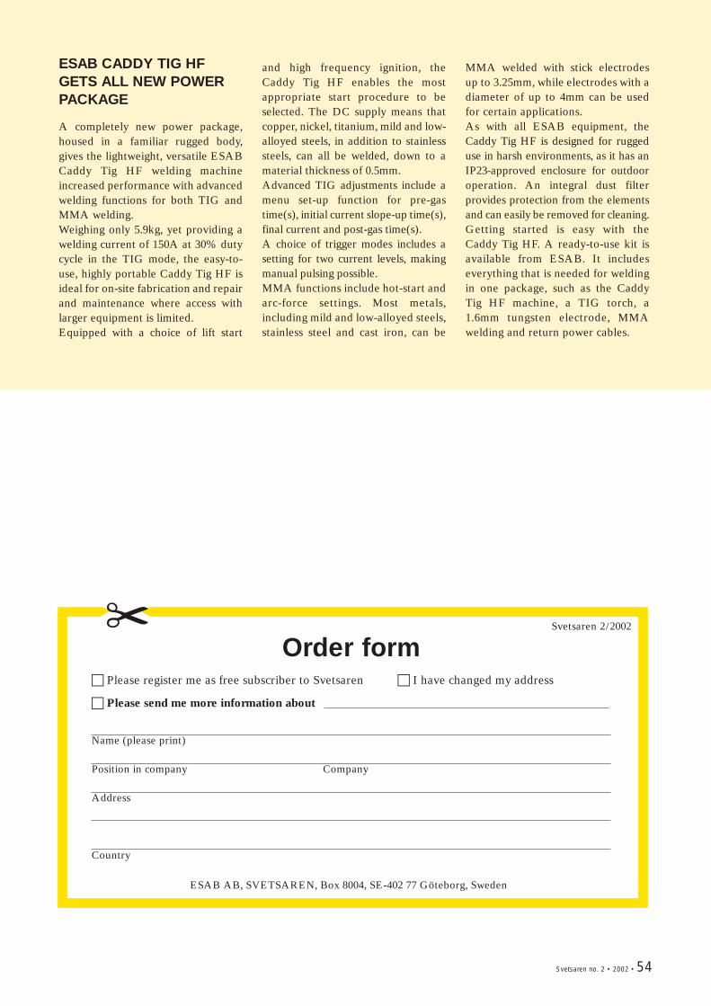
Svetsaren no. 2 • 2002 • 54
Order form! Please register me as free subscriber to Svetsaren ! I have changed my address
! Please send me more information about
Name (please print)
Position in company Company
Address
Country
ESAB AB, SVETSAREN, Box 8004, SE-402 77 Göteborg, Sweden
Svetsaren 2/2002
ESAB CADDY TIG HFGETS ALL NEW POWERPACKAGE
A completely new power package,housed in a familiar rugged body,gives the lightweight, versatile ESABCaddy Tig HF welding machineincreased performance with advancedwelding functions for both TIG andMMA welding.Weighing only 5.9kg, yet providing awelding current of 150A at 30% dutycycle in the TIG mode, the easy-to-use, highly portable Caddy Tig HF isideal for on-site fabrication and repairand maintenance where access withlarger equipment is limited. Equipped with a choice of lift start
and high frequency ignition, theCaddy Tig HF enables the mostappropriate start procedure to beselected. The DC supply means thatcopper, nickel, titanium, mild and low-alloyed steels, in addition to stainlesssteels, can all be welded, down to amaterial thickness of 0.5mm.Advanced TIG adjustments include amenu set-up function for pre-gastime(s), initial current slope-up time(s),final current and post-gas time(s). A choice of trigger modes includes asetting for two current levels, makingmanual pulsing possible.MMA functions include hot-start andarc-force settings. Most metals,including mild and low-alloyed steels,stainless steel and cast iron, can be
MMA welded with stick electrodesup to 3.25mm, while electrodes with adiameter of up to 4mm can be usedfor certain applications.As with all ESAB equipment, theCaddy Tig HF is designed for ruggeduse in harsh environments, as it has anIP23-approved enclosure for outdooroperation. An integral dust filterprovides protection from the elementsand can easily be removed for cleaning.Getting started is easy with theCaddy Tig HF. A ready-to-use kit isavailable from ESAB. It includeseverything that is needed for weldingin one package, such as the CaddyTig HF machine, a TIG torch, a1.6mm tungsten electrode, MMAwelding and return power cables.

ESAB AB, Box 8004, S-402 77 Göteborg, SwedenTel. +46 31 50 90 00. Fax. +46 31 50 93 90
Internet: http://www.esab.com