Embed Size (px)
Citation preview
SVC-400Smart Valve Controller
Four Station Battery Powered Irrigation Controller
Owner’s Manual and Installation Instructions
®


TABLE OF CONTENTS........................................................................................Introduction ...................................................................................................................................................................... 1SVC Components............................................................................................................................................................... 2
LCD Display .................................................................................................................................................................. 2Control Buttons ............................................................................................................................................................. 3
SVC Features..................................................................................................................................................................... 4Accessories....................................................................................................................................................................... 4Connecting the Battery ...................................................................................................................................................... 5Attaching DC Latching Solenoids to the SVC ....................................................................................................................... 6Mounting to a Hunter Valve ................................................................................................................................................ 7Alternate Mounting Methods .............................................................................................................................................. 8Connecting a Weather Sensor ............................................................................................................................................ 9Programming the Controller ..............................................................................................................................................10
Setting the Date and Time .............................................................................................................................................10Setting Watering Start Times.........................................................................................................................................11Eliminating a Start Time ................................................................................................................................................11Setting the Run Time (Length of Watering) ....................................................................................................................11Setting Days to Water ...................................................................................................................................................12Selecting Specific Days of the Week to Water ................................................................................................................12Selecting Interval Watering ...........................................................................................................................................12Programming Stations to Operate Together....................................................................................................................13

1
System Off ...................................................................................................................................................................13To Activate the Controller from the System Off Model ....................................................................................................13Programmable Rain Off.................................................................................................................................................14Manual Watering ..........................................................................................................................................................14To Suspend Manual Watering to All Stations Operating .................................................................................................15To Suspend Manual Watering to Individual Stations Operating .......................................................................................15
Battery Life Indicator ........................................................................................................................................................16Troubleshooting Guide ......................................................................................................................................................17
TABLE OF CONTENTS (continued)...................................................................

1
INTRODUCTION ..................................................................................................The Hunter Smart Valve Controller (SVC) is the ideal choice for reliable operation in absence of standard electrical power. If you’re not watering an area simply because of the inability of getting wires from the controller to the valves, Hunter’s SVC battery operated controllers are just the answer.
The Smart Valve Controller mounts directly to a valve quickly and easily – without screws, drills or wires. Its rugged design and solid construction ensures that it can handle the harsh environment of the valve box. It is fully submersible and resists moisture intrusion, mud and debris as deep as 12 feet. Operates off a single 9-volt battery that’s guaranteed to provide power for at least a year. It’s also simple to program, with an easy to read and understand LCD display, along with push button operation.
For isolated sites, power-restricted areas and special irrigation applications, the new Hunter Smart Valve Controller is your solution.
2 3
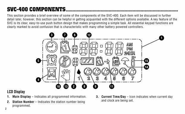
LCD Display1. Main Display – Indicates all programmed information.
2. Station Number – Indicates the station number being programmed.
3. Current Time/Day – Icon indicates when current day and clock are being set.
1
2
7
4
5
63
8 910 11
12
15
14
SVC-400 COMPONENTS....................................................................................This section provides a brief overview of some of the components of the SVC-400. Each item will be discussed in further detail later, however, this section can be helpful in getting acquainted with the different options available. A key feature of the SVC is its clear, easy-to-use push button design that makes programming a simple task. All essential keypad functions are clearly marked to avoid confusion that is characteristic with many other battery powered controllers.
13
2 3
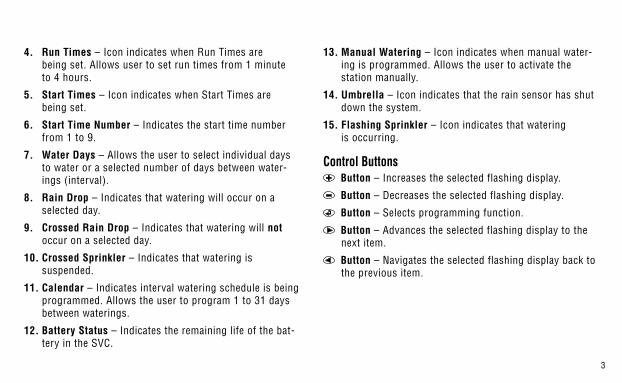
4. Run Times – Icon indicates when Run Times are being set. Allows user to set run times from 1 minute to 4 hours.
5. Start Times – Icon indicates when Start Times are being set.
6. Start Time Number – Indicates the start time number from 1 to 9.
7. Water Days – Allows the user to select individual days to water or a selected number of days between water-ings (interval).
8. Rain Drop – Indicates that watering will occur on a selected day.
9. Crossed Rain Drop – Indicates that watering will not occur on a selected day.
10. Crossed Sprinkler – Indicates that watering is suspended.
11. Calendar – Indicates interval watering schedule is being programmed. Allows the user to program 1 to 31 days between waterings.
12. Battery Status – Indicates the remaining life of the bat-tery in the SVC.
13. Manual Watering – Icon indicates when manual water-ing is programmed. Allows the user to activate the station manually.
14. Umbrella – Icon indicates that the rain sensor has shut down the system.
15. Flashing Sprinkler – Icon indicates that watering is occurring.
Control Buttons Button – Increases the selected flashing display.
Button – Decreases the selected flashing display.
Button – Selects programming function.
Button – Advances the selected flashing display to the next item.
Button – Navigates the selected flashing display back to the previous item.

4 5
ACCESSORIES......................................................................................................
Valve Mounting Clip Universal Mounting AdapterProtective Rubber Cover
SVC FEATURES....................................................................................................• Simple push button programming
• Operates up to four valves
• Large Liquid Crystal Display (LCD) with easy to understand icons
• Operates on a standard 9-volt alkaline battery
• Days-of-the-week water schedule
• Up to nine start times per day
• Run times from 1 minute to 4 hours
• Manual watering
• Low battery status shows status of life of battery
• Rain sensor (or other micro-switch sensor) compatible
• Multiple mounting options

4 5
CONNECTING THE BATTERY............................................................................The SVC-400 uses a standard 9-volt alkaline battery (not included) to operate the valve and program the controller. The life of the battery is determined by the number of valve actuations, however, under normal conditions the battery should provide at least one full year of service.
NOTE: The SVC has non-volatile memory which allows for the battery to be removed without losing any program information.
To Install the Battery:1. Unscrew the rear half of the SVC body to gain access to
the battery compartment.
2. Snap the battery into the battery holder (use a high quality 9 volt akaline battery).
NOTE: The battery holder is designed so that the battery can only be inserted one way.
3. Make sure no water is inside the battery compartment. Screw the SVC body halves together to seal the compartment.

6 7
ATTACHING DC LATCHING SOLENOIDS TO THE SVC ..................................The SVC-400 is capable of operating up to four individual DC latching solenoids. Hunter DC solenoids (P/N 458200) can easily be installed on all Hunter Plastic Valves. Sole-noids must be ordered separately.
NOTE: Must use DC Latching Solenoids. 24VAC Solenoids will not operate with the SVC-400.
To Wire DC Solenoids to the SVC:1. Attach the black leads from each solenoid to the single
common wire (black lead) coming from the SVC. Secure all wire connections with waterproof connectors.
2. Attach one red wire from each solenoid to the cor-responding station wire (red lead) from the SVC. The station numbers are identified on the face of the SVC. Secure all wire connections with waterproof connectors.
NOTE: The maximum wire distance between the solenoid and SVC is 100 feet (18 gauge minimum wire size).
The SVC can also operate non-Hunter DC latching sole-noids. Below is a list of SVC compatible solenoids.
Model Solenoid
Baccara G75-0-1002
Bermad S392-2
Nelson 8090
Rain Bird TBOSPSOLStation Wire (Red Leads)
Common Wire (Black Leads)

6 7
MOUNTING TO A HUNTER VALVE...................................................................The SVC can easily be mounted on any Hunter plastic valve. A specially designed valve mounting clip makes installation a snap.
A protective rubber cover is provided to prevent dirt from accumulating on the face of the SVC.
To Mount the SVC to a Valve (Figure 1):1. Unscrew the existing solenoid from the valve.
2. Screw the Hunter DC latching solenoid (P/N 458200) into the valve bonnet.
3. Attach the large end of the valve mounting clip to the middle of the SVC body.
4. Snap the small end of the valve mounting clip to the solenoid.
Mounting Clip

8 9
Along with the universal mounting clip, a mounting adapter is also provided with the SVC. This mounting adapter allows for alternate methods of mounting the controller either to the side of the valve box or stake mounted within the valve box.
Valve Box Mounting Method (Figure 2)1. Position the universal mounting adapter on the side of
the valve box. Make sure that the bracket is positioned so that the controller will not interfere with the valve box cover when closed.
2. Drive two screws to secure the adapter to the side of the valve box.
ALTERNATE MOUNTING METHODS...............................................................3. Attach the SVC to the mounting clip and slide it on the
end of the mounting adapter.
Stake Mounting Method (Figure 3)The universal mounting adapter can also be used to stake mount the SVC.
1. Cut a section of 1⁄2" diameter plastic pipe.
2. Drive the pipe into the ground inside the valve box to the desired height of the controller.
3. Slip the mounting adapter on top of the pipe.
4. Attached the SVC to the mounting clip and slide onto the adapter.
Mounting Clip
Mounting Adapter
Mounting Clip
Mounting Adapter
Plastic Pipe

8 9
A Hunter Mini-Clik® rain sensor can be connected to the SVC. The purpose of this sensor is to stop watering when weather conditions dictate.
NOTE: When the Rain Sensor is interrupt-ing the watering, the display will show the System Off icon , “OFF” and on the display.
To Connect a Weather Sensor to the SVC:1. Cut the yellow wire loop attached to the SVC at approxi-
mately the middle of the loop.
2. Remove approximately 1⁄2" (13mm) of insulation from each wire. Attach one yellow wire to each of the wires of the weather sensor. You can mount the rain sensor up to 100 feet from the SVC-400 controller (18 GA mini-mum wire size).
3. Secure wire connections with waterproof connectors.
CONNECTING A WEATHER SENSOR ..............................................................
Hunter Model Mini-Clik®
10 11
The SVC-400 is easy to program. The easy-to-understand icons and push button design allows you to step through the process of programming and activate manual watering with the press of a button.
The SVC-400 utilizes independent station programming. For each station being programmed, you need to program at least one Start Time, a Run Time and Water Day(s). The button allows you to quickly navigate among pro-gramming options.
The SVC display shows time and day when the button is pressed. The button allows you to easily navigate among programming options. During a short period of inactivity, the display will shut off to retain battery power. When programming, the flashing portion of the display can be changed by pressing the or buttons. To change something that is not flashing, press the or buttons until the desired item is flashing.
The SVC allows for up to 9 start times per day. Multiple start times permit morning, afternoon and evening water-ing, perfect for the establishment of new lawns and thirsty
annual flowers. Simply designate the days of the week you want to water. The SVC makes it easy.
Setting the Date and Time1. Press the button until the Current Time/Day icon
is displayed.
2. Hours will be flashing. Press the or button to change the hour shown on the display. Press the to proceed to setting the minutes.
3. Minutes will be flashing. Use the or button to change the minutes shown on the display. Press the to proceed to select AM, PM or 24 hour time.
4. The time will be displayed, and the time of day flashing. Press the or button to select AM, PM or 24 hour. Press the to proceed to setting the day of the week.
5. The number 1 will be flashing at the bottom of the dis-play, indicating the first day of the week. Press the or buttons to select the day of the week (1 through 7) corresponding to the day.
The time and day have now been set.
PROGRAMMING THE SVC-400 CONTROLLER..............................................
10 11
Setting Watering Start Times1. Push the button until the Start Times icon is
displayed. A Start Time or “Off” will be flashing. The number directly to the left of the start time number (1 through 9) indicates the start time number. The number directly below the start time number indicates the sta-tion being programmed.
2. Use the or button to change the start time. (The start times advance in 15 minute increments.) Hold either button down for 1 second to change times rapidly.
3. To add another start time to the station, press the button. The start time icon and start time number will be flashing. Use the or buttons to change the start time number.
4. Press the button. The start time will be flashing. Use the or buttons to change the start time.
5. To program start times for another station, press the button. The station number will be flashing. Use the or buttons to select the next station (1 through 4). Repeat steps 3 and 4.
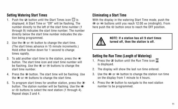
Eliminating a Start TimeWith the display in the watering Start Time mode, push the
or buttons until you reach 12:00 AM (midnight). From here push the button once to reach the OFF position.
NOTE: If a station has all 9 start times turned off, then the station is off.
Setting the Run Time (Length of Watering)1. Press the button until the Run Time icon
is displayed.
2. The display will show the last run time entered.
3. Use the or button to change the station run time on the display from 1 minute to 4 hours.
4. Press the button to navigate to the next station number to be programmed.
12 13
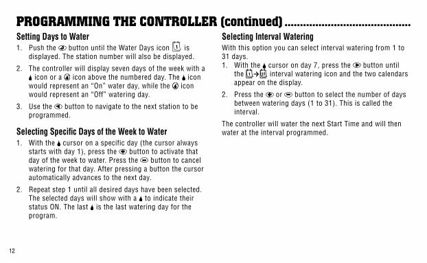
PROGRAMMING THE CONTROLLER (continued) .........................................Setting Days to Water1. Push the button until the Water Days icon is
displayed. The station number will also be displayed.
2. The controller will display seven days of the week with a icon or a icon above the numbered day. The icon
would represent an “On” water day, while the icon would represent an “Off” watering day.
3. Use the button to navigate to the next station to be programmed.
Selecting Specific Days of the Week to Water1. With the cursor on a specific day (the cursor always
starts with day 1), press the button to activate that day of the week to water. Press the button to cancel watering for that day. After pressing a button the cursor automatically advances to the next day.
2. Repeat step 1 until all desired days have been selected. The selected days will show with a to indicate their status ON. The last is the last watering day for the program.
Selecting Interval WateringWith this option you can select interval watering from 1 to 31 days.1. With the cursor on day 7, press the button until
the interval watering icon and the two calendars appear on the display.
2. Press the or button to select the number of days between watering days (1 to 31). This is called the interval.
The controller will water the next Start Time and will then water at the interval programmed.

12 13
Programming Stations to Operate TogetherThe SVC-400 allows for automatic watering of multiple valves at the same time. Up to four stations can operate at the same time. If more than one station has the same start time, they will operate together (they must also be pro-grammed with the same water day). For example, if Station 1 and 2 both have been programmed with start times of 8:00 AM, they will both turn on and run at the same time.
The SVC allows for start time stacking which is help-ful when system capacity is not adequate to support the operation of multiple valves at the same time. Let's assume a scenario in which Station 1 is programmed to start at 8:00 AM and run for 15 minutes, and Station 2 is pro-grammed to start at 8:10 AM and run for 15 minutes. Station 1 watering run time overlaps Station 2 start time. The SVC will wait until Station 1 completes watering until it starts Station 2. In this scenario, Station 2 will start at 8:15 AM.
System OffThis function permits the user to shut the system off for an indefinite period of time.1. Press the mode button until the Crossed Sprin-
kler icon is displayed.
2. Wait 4 seconds and “Off” will appear on the display. The SVC is now in the System Off mode and will remain off until it is turned back on again.
To Activate the Controller from the System Off Model1. Press the mode button once. The display will wake
up in the System Off mode.
2. Press the mode button again and “Off” will disappear from the display. The display will show the current time. Your controller is now on and will water automatically based upon the current program.

14 15
Programmable Rain OffThis feature permits the user to stop all programmed water-ings for a designated period from 1 to 7 days. At the end of the programmable rain off period, the controller will resume normal automatic operation.1. Press the button until the System Off icon is
displayed. Wait 4 seconds and “Off” will appear on the display.
2. Press the button and a 1 will be displayed. The 1 will be blinking at this point.
3. Press the button as many times as needed to set the number of days off desired (up to 7). The SVC will wait the number of days selected and then reactivate automatic watering.
Manual WateringThe SVC-400 features a simple one touch manual start. One or more stations can be programmed to run manually at the same time.
To Activate a Manual Watering:1. Press the button once to display the current time
of day.
PROGRAMMING THE CONTROLLER (continued) .........................................2. Press and hold the button for two seconds to display
the Manual Watering icon. The station number will also be displayed
3. Use the or button to adjust the manual water run time from 1 minute to 4 hours.
4. Release the buttons and the controller will count down 10 seconds before activating the manual cycle.
5. The flashing sprinkler icon will appear on the display when watering is occurring.
6. To activate another station, use the button to select the station you would like to manually water, repeat steps 3 and 4.
Note: While manual watering is occurring the display will briefly display the station number and the time watering remaining for each station that is operating. The manual water run time can be increased or decreased for any time that the station is displayed.

14 15
To Suspend Manual Watering to All Stations Operating:1. Press the button until the System Off icon is
displayed. Wait 4 seconds and “OFF” will appear on the display. All stations will turn off.
2. Press the button again and the current time and day will be displayed. The SVC will now water based upon the current program.
To Suspend Manual Watering to Individual Stations Operating:1. Press the button and the display will show each of
the stations operating manually.
2. When the station number appears for the station that you would like to suspend manual watering, press the button once. The time remaining displayed will change to “Off” and the station will turn off.
3. Repeat steps 1 and 2 to suspend watering for additional stations.

16 17
BATTERY LIFE INDICATOR ...............................................................................The battery life status icon is a quick way to determine the remaining life of the installed battery without having to remove the battery from the controller. A battery life status icon will appear along with the time and day on the display. A fully charged battery will show all three segment of the battery dark . As the battery is expended, the segments will appear as outlines .

16 17
TROUBLESHOOTING GUIDE .............................................................................Problem Causes SolutionsThere is no display Display is off.
Battery is dead.Press any button for 1 second.Replace the battery.
Display indicates watering but none is occurring.
No water pressure.Faulty solenoid.Imcompatible solenoid.
Turn on main system supply.Replace solenoid.Must use Hunter DC Latching Solenoid (P/N 458200) or other compatible DC latching solenoid.
Automatic irrigation does not start at start time.
Controller in System Off mode.AM/PM of time of day not set correctly.AM/PM of start time not set correctly.
Verify that controller is programmed for automatic watering.Correct AM/PM of time of day.Correct AM/PM of start time.
Rain sensor does not suspend watering.
Rain sensor defective or miswired. Verify proper operation of the rain sensor and wire connections (see page 9).
Controller waters more than one time.
Too many start times have been entered (up to 9 start times per day).
Each station start time activates a station run time. Set only one start time for once per day watering.

18
NOTES...................................................................................................................

18

Hunter Industries Incorporated • The Irrigation Innovators1940 Diamond Street • San Marcos, California 92069 © 2003 Hunter Industries Incorporated
www.HunterIndustries.com P/N 715064 LIT-382 10/03