Embed Size (px)
Citation preview
IM-S13-33 CTLS Issue 10 1
1. Safety information
2. General product information
3. Supply
4. Handling
5. Before fitting the valve
6. Installation
7. Damage prevention
8. Commissioning
9. Testing during use
10. Maintenance
© Copyright 2019
Printed in GB
2520051/10
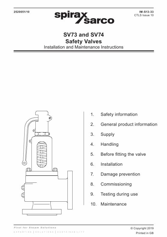
SV73 and SV74Safety Valves
Installation and Maintenance Instructions
IM-S13-33CTLS Issue 10

IM-S13-33 CTLS Issue 102
Safe operation of the unit can only be guaranteed if it is properly installed, commissioned and maintained by a qualified person (see Section 1.11) in compliance with the operating instructions. General installation and safety instructions for pipeline and plant construction, as well as the proper use of tools and safety equipment must also be complied with.
1.1 Intended useReferring to these Installation and Maintenance Instructions, Name-plate and Technical Information Sheet, check that the product is suitable for the intended use/application. The SV74 safety valve range complies with the requirements of the Pressure Equipment Directive (PED) and carry the mark. It falls within Category 4 for Group 2 Gases.
The SV73 safety valve body, bonnet and cap are manufactured in grey cast iron and as such does not fall within the scope of the Pressure Equipment Directive. The SV73 therefore, cannot be used on any installation within the EU.
i) The SV74 has been specifically designed for use on steam, air and inert industrial gases in Group 2 of the above mentioned Pressure Equipment Directive.
ii) Check material suitability, pressure and temperature and their maximum and minimum values. If the maximum operating limits of the product are lower than those of the system in which it is being fitted, or if malfunction of the product could result in a dangerous overpressure or overtemperature occurance, ensure a safety device is included in the system to prevent such over-limit situations.
iii) Determine the correct installation situation and direction of fluid flow.
iv) Spirax Sarco products are not intended to withstand external stresses that may be induced by any system to which they are fitted. It is the responsibility of the installer to consider these stresses and take adequate precautions to minimise them.
v) Remove protective covers from all connections and protective film from all name-plates, where appropriate, before installation on steam or other high temperature applications.
1.2 AccessEnsure safe access and if necessary a safe working platform (suitably guarded)before attempting to work on the product. Arrange suitable lifting gear if required.
1.3 LightingEnsure adequate lighting, particularly where detailed or intricate work is required.
1.4 Hazardous liquids or gases in the pipelineConsider what is in the pipeline or what may have been in the pipeline at some previous time. Consider; flammable materials, substances hazardous to health, extremes of temperature.
1.5 Hazardous environment around the productConsider; explosion risk areas, lack of oxygen (e.g. tanks, pits), dangerous gases, extremes of temperature, hot surfaces, fire hazard (e.g. during welding), excessive noise, moving machinery.
1. Safety information

IM-S13-33 CTLS Issue 10 3
1.6 The systemConsider the effect on the complete system of the work proposed. Will any proposed action (e.g. closing isolation valves, electrical isolation) put any other part of the system or any personnel at risk? Dangers might include isolation of vents or protective devices or the rendering ineffective of controls or alarms. Ensure isolation valves are turned on and off in a gradual way to avoid system shocks.
1.7 Pressure systemsEnsure that any pressure is isolated and safely vented to atmospheric pressure. Consider double isolation (double block and bleed) and the locking or labelling of closed valves. Do not assume that the system has depressurised even when the pressure gauge indicates zero.
1.8 TemperatureAllow time for temperature to normalise after isolation to avoid danger of burns.
1.9 Tools and consumablesBefore starting work ensure that you have suitable tools and / or consumables available. Use only genuine Spirax Sarco replacement parts.
1.10 Protective clothingConsider whether any protective clothing is required by yourself and / or others in the vicinity to protect against the hazards of, for example, chemicals, high / low temperature, noise, falling objects, and dangers to eyes and face.
1.11 Permits to workAll work must be carried out or be supervised by a suitably competent person.Installation and operating personnel should be trained in the correct use of the product according to these instructions.Where a formal 'permit to work' system is in force it must be complied with. Where there is no such system, it is recommended that a responsible person should know what work is going on and, where necessary, arrange to have an assistant whose primary responsibility is safety.Post 'warning notices' if necessary.
1.12 HandlingWhere the weight of the product exceeds 20 kg (44 lb) it is recommended that suitable lifting equipment is used to prevent personal injury.
1.13 Residual hazardsIn normal use the external surface of the product may be very hot. If used at the maximum permitted operating conditions the surface temperature of some products may reach temperatures in excess of 350 °C (662 °F).Many products are not self-draining. Take due care when dismantling or removing the product from an installation (refer to Section 10, 'Maintenance instructions').

IM-S13-33 CTLS Issue 104
1.14 FreezingProvision must be made to protect products which are not self-draining against frost damage if they are inoperative in environments where they may be exposed to temperatures below freezing point.
1.15 Safety information - Product specificThis product should not be dismantled without first releasing the compression on the adjustment spring.If the valve is to be installed outdoors, the inlet neck and body of the valve must be insulated to reduce the effects of temperature variation.
1.16 DisposalUnless otherwise stated in the Installation and Maintenance Instructions, this product is recyclable and no ecological hazard is anticipated with its disposal providing due care is taken.
1.17 Returning productsCustomers and stockists are reminded that under UK and EC Health, Safety and Environment Law, when returning products to Spirax Sarco they must provide information on any hazards and the precautions to be taken due to contamination residues or mechanical damage which may present a health, safety or environmental risk. This information must be provided in writing including Health and safety data sheets relating to any substances identified as hazardous.
1.18 Working safely with cast iron products on steamCast iron products are commonly found on steam and condensate systems. If installed correctly using good steam engineering practices, it is perfectly safe. However, because of its mechanical properties, it is less forgiving compared to other materials such as SG iron or carbon steel. The following are the good engineering practices required to prevent waterhammer and ensure safe working conditions on a steam system.
Safe HandlingCast Iron is a brittle material. If the product is dropped during installation and there is any risk of damage the product should not be used unless it is fully inspected and pressure tested by the manufacturer.

IM-S13-33 CTLS Issue 10 5
Prevention of waterhammer Steam trapping on steam mains:
Steam Mains - Do's and Don'ts:
Steam Steam
Flow Flow
30 - 50 metre intervalsGradient 1:100Gradient 1:100
Trap setTrap set
Trap set
CondensateCondensate
Condensate
Steam
Steam

IM-S13-33 CTLS Issue 106
Prevention of tensile stressing Pipe misalignment:
Installing products or re-assembling after maintenance:
Thermal expansion:
Do not over tighten.Use correct torque figures.
11
4 2
3
82
6
3
7
Flange bolts should be gradually tightened across diameters to ensure even load and alignment.
Guides
Guides
Limit rods
Limit rods
Fixing pointMedium distance
Small lateral movement
Small lateral movement
Large lateral movement
Large lateral movement
Short distance Fixing point
Axial movement
Axial movement
Guides
Guides
5
4

IM-S13-33 CTLS Issue 10 7
Fig. 1 Typical installation of safety valve, downstream of pressure reducing valve station
2.1 DescriptionThe SV7 series is a semi-nozzle, full lift safety valve suitable for steam, air and other inert industrial gases. They are primarily intended for use on power boilers and unfired pressure vessels and comply with Section I and VIII of the ASME Boiler and Pressure Vessel Code.
Available typesThere are two body material variations for the SV7 series safety valves:
SV73 Grey cast iron body with stainless steel trim in orifice sizes 'J' to 'R'
SV74 Carbon steel body with stainless steel trim in orifice sizes 'F' to 'R'
Standards and approvals The SV7 is designed in accordance with ASME Boiler and Pressure Vessel Codes Section I and Section VIII. The National Board of Boiler and Pressure Vessel Inspectors certifies design and capacities. Each valve may be stamped with the ASME 'UV' Code symbol for Section VIII valves or the ASME 'V' code symbol for Section I valves.
The SV74 is marked for compliance with Pressure Equipment Directive (PED).
Seat tightness is in accordance with ASME /API STD 527 - 1992.
CertificationA manufacturers' Typical Test Report is provided as standard for each valve which will include the valve set and hydraulic test pressure. Also available on request is material certification in accordance with EN 10204 3.1.
2.2 Sizes and end connectionsValves are available in the following sizes:
Type and size range Inlet Outlet
SV73
1½" x 2½" to 3" x 4" Screwed NPT female Screwed NPT female
1½" x 2½" to 3" x 4" Flanged ASME 250 Screwed NPT female
3" x 4" to 6" x 8" Flanged ASME 250 Flanged ASME 125
SV74 1½" x 2" to 6" x 8" Flanged ASME 300 Flanged ASME 150
Steam supply
Condensate
Reducing valve
To safe areaSafety valve
Small bore drain
2. General product information

IM-S13-33 CTLS Issue 108
2.3 Pressure/temperature limits - SV73Please contact Spirax Sarco, when so required, for relevant details regarding the maximum allowable limits that the shell can withstand.
The product must not be used in this region.
A - B Limit for valves with a flanged inlet.
C - D Limit for valves with a screwed inlet.
Body design conditions ANSI 250
Set pressure range
Maximum 250 psi g
Minimum 5 psi g
Minimum 15 psi g ASME code stamped
Design temperatureMaximum
Screwed inlet 406 °F
Flanged inlet 446 °F
Minimum -20 °F
Operating temperatureMaximum Screwed inlet 406 °F
Flanged inlet 446 °F
Performance data
Overpressure
ASME I Steam 3%
ASME VIIISteam 10%
Air/gas 10%
Blowdown limits
ASME I Steam 2 - 6%
ASME VIIISteam 7%
Air/gas 7%
Derated coefficient of discharge valuesSteam 0.955
Air/gas 0.955
Maximum permitted backpressure up to: 10% of set pressure
Tested at a maximum inlet cold hydraulic test pressure of: 600 psi g
Pressure psi g
Tem
pera
ture
°F
Steam saturation curve
A
BD
C

IM-S13-33 CTLS Issue 10 9
The product must not be used in this region.
A - B To avoid spring damage, do not exceed an operating temperature of 446 °F.
Body design conditions ANSI 300
Set pressure range
Maximum 300 psi g
Minimum 5 psi g
Minimum 15 psi g ASME code stamped
Design temperatureMaximum 750 °F
Minimum -20 °F
Operating temperature Maximum 446 °F
Performance data
Overpressure
ASME I Steam 3%
ASME VIIISteam 10%
Air/gas 10%
Blowdown limits
ASME I Steam 2 - 6%
ASME VIIISteam 7%
Air/gas 7%
Derated coefficient of discharge valuesSteam 0.955
Air/gas 0.955
Maximum permitted backpressure up to: 10% of set pressure
Tested at a maximum inlet cold hydraulic test pressure of: 1015 psi g
2.4 Pressure/temperature limits - SV74Please contact Spirax Sarco, when so required, for relevant details regarding the maximum allowable limits that the shell can withstand.
Tem
pera
ture
°F
Pressure psi g
A BSteam saturation curve

IM-S13-33 CTLS Issue 1010
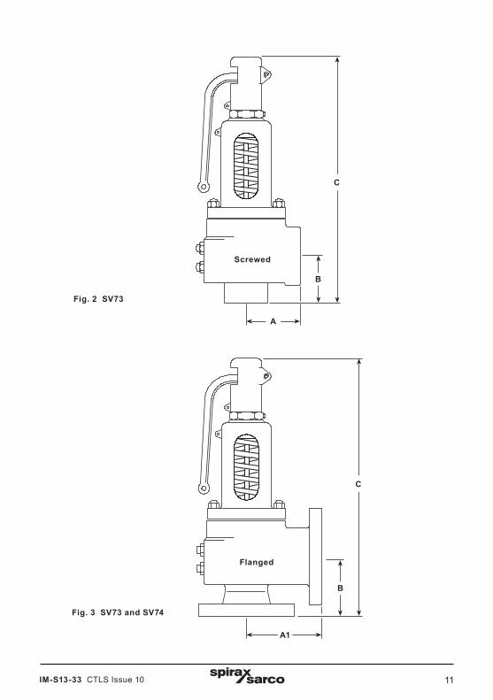
2.5 Dimensions, weights and orifice sizes (approximate) in inches and lbs
SV73
Valve inlet Valve outlet Orifice A A1 B C Weight
Size Connection Size Connection ins ins ins ins Ibs
1½" NPT 2½" NPT J 3.5 - 4.3 15.8 33
2" NPT 3" NPT K 4.0 - 4.6 17.1 46
2½" NPT 4" NPT L 4.6 - 5.5 18.5 66
3" NPT 4" NPT M 5.1 - 5.6 24.3 93
1½" ASME 250 2½" NPT J 3.5 - 4.3 15.8 38
2" ASME 2502½" NPT J 3.5 - 4.3 15.8 40
3" NPT K 4.0 - 4.6 17.1 49
2½" ASME 2503" NPT K 4.0 - 4.6 17.1 51
4" NPT L 4.6 - 5.5 19.5 71
3" ASME 250 4"
NPTL 4.6 - 5.5 19.5 73
M 5.1 - 5.4 24.3 101
ASME 125L - 5.5 5.5 19.5 82
M - 5.5 5.4 24.3 110
4" ASME 250 6" ASME 125N - 7.1 6.8 26.5 187
P - 7.1 6.8 28.5 196
6" ASME 250 8" ASME 125Q - 9.3 9.3 34.5 355
R - 10.0 10.9 43.9 595
SV74
Valve inlet Valve outlet Orifice A1 B C Weight
Size Connection Size Connection ins ins ins Ibs
1½" ASME 300
2" ASME 150F 4.25 4.5 15.7 31
G 4.25 4.5 15.7 31
2½" ASME 150H 4.90 4.8 16.2 46
J 4.90 4.8 16.2 46
2" ASME 300 3" ASME 150 K 5.60 5.1 18.5 62
2½" ASME 300 4" ASME 150 L 6.40 6.1 20.1 90
3" ASME 300 4" ASME 150 M 6.50 6.5 25.0 117
4" ASME 300 6" ASME 150N 7.50 7.2 26.7 198
P 8.30 7.1 28.7 212
6" ASME 300 8" ASME 150Q 9.40 9.9 34.8 384
R 10.00 10.9 43.9 633
Note: Drain hole connection ½" NPT on all valve sizes
IM-S13-33 CTLS Issue 10 11
Fig. 2 SV73
Fig. 3 SV73 and SV74
C
B
A
C
B
A1
Screwed
Flanged

IM-S13-33 CTLS Issue 1012
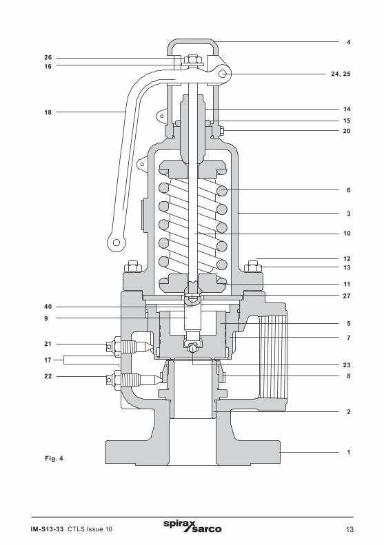
2.6 MaterialsNo. Part Material
1 BodySV73 Cast iron ASTM A126 Class B
SV74 Cast steel ASME SA 216 Gr. WCB
2 SeatF to H orifice Stainless steel ASTM A479 304
J to R orifice Stainless steel ASTM A351 Grade CF8
3 BonnetSV73 Cast iron ASTM A126 Class B
SV74 Cast steel ASME SA 216 Gr. WCB
4 Cap Cast iron ASTM A126 Class B
5 DiscF to H orifice Stainless steel ASTM A479 304
J to R orifice Stainless steel ASTM A217 CA15
6 Spring Chrome - vanadium alloy steel
7 Upper adjusting ring Stainless steel ASTM A351 Grade CF8
8 Lower adjusting ring Stainless steel ASTM A351 Grade CF8
9 Stem (lower) Stainless steel ASTM A479 Type 410
10 Stem (upper) Stainless steel ASTM A479 Type 410
11 Spring washers (2 off) Steel ASTM A105
12 Bonnet stud Steel ASTM A193 Grade B7
13 Bonnet nut Steel ASTM A194 Grade 2H
14 Adjusting screw Stainless steel ASTM A479 Type 410
15 Adjusting screw nut Carbon steel
16 Release ring Carbon steel
17 Lock-nut (2 off) Carbon steel
18 Lever Grey iron
20 Cap set screw Carbon steel
21 Upper adjusting ring pin Stainless steel
22 Lower adjusting ring pin Stainless steel
23 Disc ball Stainless steel
24 Pin washer Carbon steel
25 Lever pin Carbon steel
26 Lock-nut Carbon steel
29 Guide plate Carbon steel
40 Stem pin Carbon steel
IM-S13-33 CTLS Issue 10 13
2
1
3
4
5
7
8
9
11
1213
14
15
6
18
20
21
2223
24, 25
26
2740
Fig. 4
17
10
16

IM-S13-33 CTLS Issue 1014
2.7 How to selectModel type SV7
Construction 34
==
Cast ironCast steel 3
ASME sectionVU
Blank
===
ASME Code Section IASME Code Section VIIIValve without code stamp
V
SV73Size and connection
ABCDEFGHIJKLNQ
==============
1½"2"2"2½"2½"3"3"3"4"6"
1½" NPT2" NPT
2½" NPT3" NPT
ASME 250ASME 250ASME 250ASME 250ASME 250ASME 250ASME 250ASME 250ASME 250ASME 250
xxxxxxxxxxxxxx
2½"3"4"4"2½"2½"3"3"4"4"4"4"6"8"
NPTNPTNPTNPTNPTNPTNPTNPTNPTNPTNPTASME 125ASME 125ASME 125
A
SV74Size and connection
STUVWXY
=======
1½"1½"2"2½"3"4"6"
ASME 300ASME 300ASME 300ASME 300ASME 300ASME 300ASME 300
xxxxxxx
2"2½"3"4"4"6"8"
ASME 150ASME 150ASME 150ASME 150ASME 150ASME 150ASME 150
Orifice area in²
FG HJKLMNPQR
===========
0.3280.5370.8411.3741.9683.0543.8464.6336.83011.81117.123
J
Set pressure Specify set pressure*SV73 5 - 250 psi g
5 - 300SV74 5 - 300 psi g
SV73
SV74
Selection example SV7 3 - V - A J 180
How to order example:1 off Spirax Sarco SV73-V-AJ safety valve having a set pressure of 180 psi g (12.5 bar g).
* Note: Set pressures below 15 psi g are not ASME coded

IM-S13-33 CTLS Issue 10 15
The internal parts of the SV7 safety valve are precision machined and assembled to maintain perfect alignment. Rough handling may damage the seats or cause sufficient misalignment to incur leakage or erratic operation. Safety valves should be handled with care.Prior to installation they should remain in the packing provided by the supplier and kept in a clean, dry, covered storage area and segregated from other valves, fittings and pipework.
5.1 Ensure that the pipework installation is suitable for the valve (see Figure 1, page 5).
5.2 Check that the details on the safety valve name-plate are compliant with the installation and process.
5.3 Blow through the pipework to ensure that it is completely free of any foreign matter that may otherwise pass to the valve seat and cause damage, leading to seat leakage. Blowdown must be carried out before installing the safety valve.
5.4 Remove all packaging and protective flange covers. Avoid getting any dirt or scale inside the valve before installation.
5.5 Visually inspect the valve for any apparent damage. Ensure all wires and seals are intact.
5.6 Ensure that the valve is set to the correct pressure, see 'Testing during use', Section 9.
4.1 Valves should be transported in the upright position.
4.2 Do not drop and avoid sudden shocks or heavy impacts.
4.3 Always store in the suppliers packaging until required.
4.4 Never carry a safety valve by the lifting lever.
Normally, the valve will be supplied set at the required pressure and sealed.ASME/API standards and local regulations require that the setting of the valve should only be carried out by an authorised/competent person.Spirax Sarco accepts no responsibility for valves which have been reset by unauthorised persons.
3. Supply
4. Handling
5. Before fitting the valve

IM-S13-33 CTLS Issue 1016
Note: Before actioning any installation observe the 'Safety information' in Section 1.
6.1 Inlet pipingThe SV7 safety valve should be installed in a vertical upright position. The inlet piping to the valve should be short and direct from the vessel or equipment being protected. The connection to the vessel should be straight or provided with a radius to permit smooth flow to the valve. Sharp corners should be avoided. Should this not be practical, then the inlet should be flared out at least one additional pipe diameter.
6.2 Outlet pipingDischarge lines from the SV7 shall be at least the same size as the valve outlet and as short and direct as possible. Discharge lines shall prevent condensate from collecting in the discharge side of the valve body and must be directed to a safe discharge area. Although the valve body will withstand a considerable mechanical load, unsupported discharge piping should be given consideration and should consist of no more than a companion flange, long radius elbow and a short vertical pipe. A Spirax Sarco drip pan elbow is an ideal choice. Care should be taken to ensure thermal expansion of piping and support does not produce strains in a valve. Spring supports are recommended where this may be the case.
6.3 Section I valvesSV7 ASME Section I valves must be connected to the boiler independent of any other connection and as close to the boiler or normal steam flow path as possible without unnecessary intervening pipe or fittings. Make sure any intervening pipe or fitting is not longer than the face-to-face dimensions of the corresponding 'T' fittings of the same diameter and pressure rating.
6.4 Section VIII valvesFor SV7 ASME Section VIII service, the valve should be connected to the vessel in the vapour space above any contained liquid or to the piping connected to the vapour space in the vessel which is to be protected. The connection between the valve and boiler or vessel shall have an area at least equal to the valve inlet.Note: Stop valves are not permitted between vessel and safety/relief valve and the discharge to atmosphere except per ASME section VIII UG-135(e).Figure 5 shows a typical installation for the SV7 safety valve.
6.5 Outlet reaction forcesThe discharge of a safety valve will impose a reactive load on the inlet of the valve and adjacent supporting vessel shell as a result of the reaction force of the flowing stream. The precise nature of the loading and the resulting stresses will depend on the configuration of the valve and discharge piping. This must be taken into consideration by those responsible for the installation of the safety valve and associated vessel or piping.Determination of outlet reaction forces is the responsibility of the designer of the vessel and/or piping.
6. Installation

IM-S13-33 CTLS Issue 10 17
Fig. 5 Typical installation
Exhaust
Drain
Discharge pipe
Support (if possible)
Inlet pipeDrain
SV7 safety valve
Drain
x 4 x Øs with 600 mm maximum
Building attachment
Øs
Øe
Note: Drain hole connection ½" NPT on all valve sizes

IM-S13-33 CTLS Issue 1018
Excessive pressure loss at the inlet of a safety valve when it operates will cause extremely rapid opening and closing of the valve, observed as chattering or hammering.This may result in reduced capacity as well as damage to seating faces and the other parts of the valve.When normal pressure is restored it is possible that the valve will leak.
7.1 SolutionPressure loss at inlet should be no more than 3% of pressure differential between set pressure and superimposed back pressure when discharging.The valve should be fitted 8-10 pipe diameters downstream of converging or diverging fittings or bends (Figure 6).Inlet branches should be as Figures 7 and 8.
Fig. 6
Fig. 7
a
8 - 10 pipe diameters downstream of converging 'Y'
fittings or bends.
ARadius 'r ' not less than inlet diameter
Inlet area 'A' approximately twice that
of area 'a'r
Fig. 8
7. Damage prevention

IM-S13-33 CTLS Issue 10 19
Note: Use suitable protection against excess heat and noise when testing safety valves.
It is recommended that the safety valve is tested for correct operation on a regular basis as part of a documented and controlled procedure, the frequency of testing is dependant on the application and system conditions and an appropriate test interval must be decided by the user or relevant insurance company.
8.1 Once the valve has been fitted check that there are no leaks from either the inlet or the outlet connections.
8.2 Test the set pressure of the valve by raising the system pressure. Ensure that the valve operates correctly at its specified set pressure as indicated on the name-plate.
8.3 Check that the overpressure is limited to 3% of the safety valve set pressure (ASME I applications) or 10% (ASME VIII applications).
8.4 Reduce the system pressure to the normal operating pressure and check that the safety valve reseats.
All safety valves should receive planned maintenance.
Note: Before actioning any maintenance work please read 'Safety information', Section 1.
SV7 safety valves are 100% tested and then sealed to prevent unauthorised adjustment or repair. Valves should be inspected regularly to assure continued safe operation and long service life. A visual inspection is recommended at two month intervals while in service, followed by a complete pressure test at least once a year.The SV7 can be operated manually by means of the test lever when the system pressure is at least 85% of the set pressure, or the system pressure may be carefully increased until the valve operates.Any valve that fails to open within 103% (ASME I) or 110% (ASME VIII) of the name-plate set pressure or fails to open or close properly must be removed for replacement or repair. Never attempt to stop leakage by compressing the spring or gagging the valve!
For repair and resetting of ASME Code Section I and VIII stamped valves, ASME authorised and approved safety valve repair facilities
must be used.
8. Commissioning
9. Testing during use
10. Maintenance

IM-S13-33 CTLS Issue 1020