Embed Size (px)
Citation preview
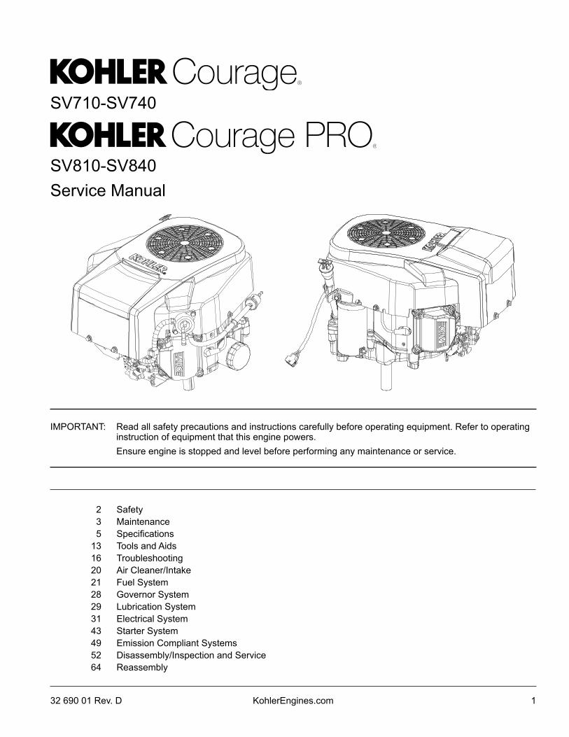
Service Manual
SV710-SV740
SV810-SV840
2 Safety3 Maintenance5 Specifications
13 Tools and Aids16 Troubleshooting20 Air Cleaner/Intake21 Fuel System28 Governor System29 Lubrication System31 Electrical System43 Starter System49 Emission Compliant Systems52 Disassembly/Inspection and Service64 Reassembly
132 690 01 Rev. D KohlerEngines.com
IMPORTANT: Read all safety precautions and instructions carefully before operating equipment. Refer to operating instruction of equipment that this engine powers.
Ensure engine is stopped and level before performing any maintenance or service.
2
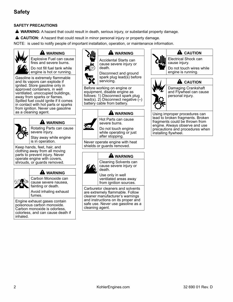
Safety
SAFETY PRECAUTIONS WARNING: A hazard that could result in death, serious injury, or substantial property damage. CAUTION: A hazard that could result in minor personal injury or property damage.NOTE: is used to notify people of important installation, operation, or maintenance information.
WARNINGExplosive Fuel can cause fires and severe burns.Do not fill fuel tank while engine is hot or running.
Gasoline is extremely flammable and its vapors can explode if ignited. Store gasoline only in approved containers, in well ventilated, unoccupied buildings, away from sparks or flames. Spilled fuel could ignite if it comes in contact with hot parts or sparks from ignition. Never use gasoline as a cleaning agent.
WARNINGRotating Parts can cause severe injury.Stay away while engine is in operation.
Keep hands, feet, hair, and clothing away from all moving parts to prevent injury. Never operate engine with covers, shrouds, or guards removed.
WARNINGCarbon Monoxide can cause severe nausea, fainting or death.Avoid inhaling exhaust fumes.
Engine exhaust gases contain poisonous carbon monoxide. Carbon monoxide is odorless, colorless, and can cause death if inhaled.
WARNING
Accidental Starts can cause severe injury or death.Disconnect and ground spark plug lead(s) before servicing.
Before working on engine or equipment, disable engine as follows: 1) Disconnect spark plug lead(s). 2) Disconnect negative (–) battery cable from battery.
WARNINGHot Parts can cause severe burns.Do not touch engine while operating or just after stopping.
Never operate engine with heat shields or guards removed.
WARNINGCleaning Solvents can cause severe injury or death.Use only in well ventilated areas away from ignition sources.
Carburetor cleaners and solvents are extremely flammable. Follow cleaner manufacturer’s warnings and instructions on its proper and safe use. Never use gasoline as a cleaning agent.
CAUTIONElectrical Shock can cause injury.Do not touch wires while engine is running.
CAUTIONDamaging Crankshaft and Flywheel can cause personal injury.
Using improper procedures can lead to broken fragments. Broken fragments could be thrown from engine. Always observe and use precautions and procedures when installing flywheel.
KohlerEngines.com 32 690 01 Rev. D
3
Maintenance
32 690 01 Rev. D KohlerEngines.com
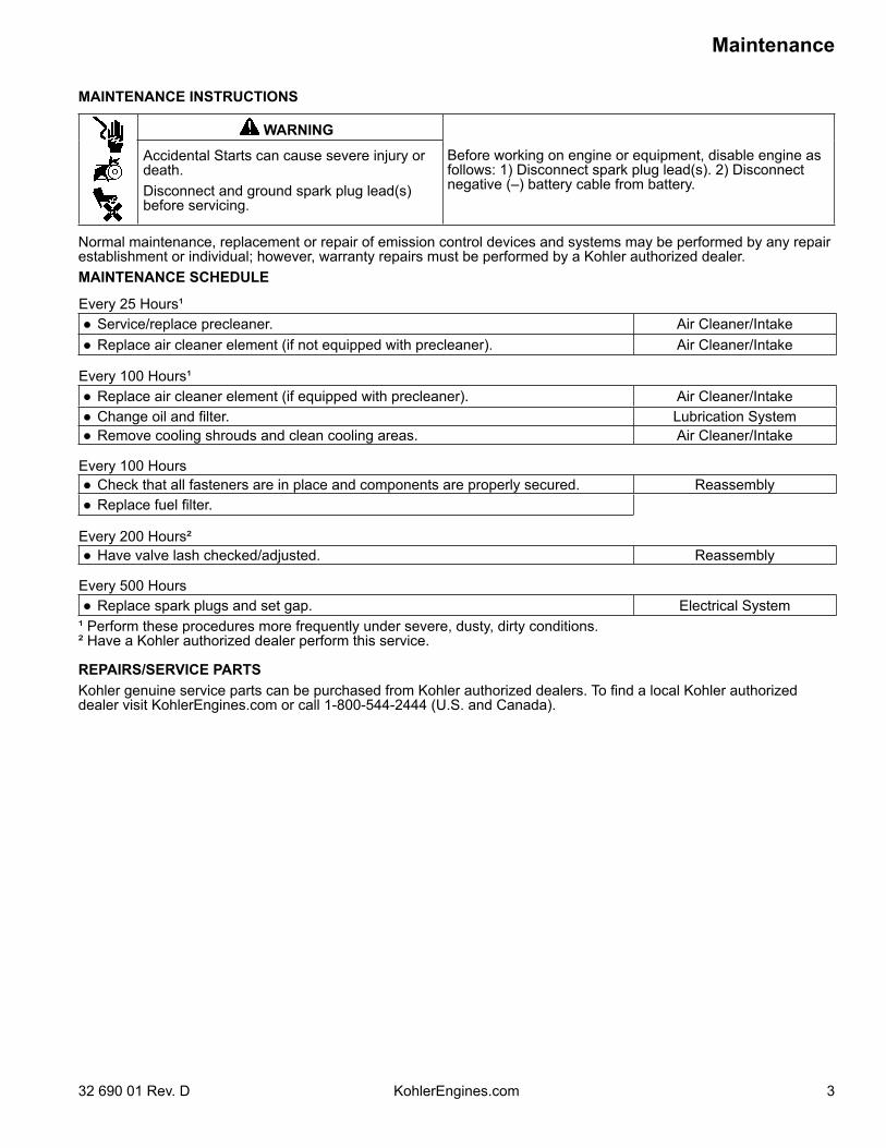
MAINTENANCE INSTRUCTIONS
WARNING
Before working on engine or equipment, disable engine as follows: 1) Disconnect spark plug lead(s). 2) Disconnect negative (–) battery cable from battery.
Accidental Starts can cause severe injury or death.Disconnect and ground spark plug lead(s) before servicing.
Normal maintenance, replacement or repair of emission control devices and systems may be performed by any repair establishment or individual; however, warranty repairs must be performed by a Kohler authorized dealer.MAINTENANCE SCHEDULE
Every 25 Hours¹● Service/replace precleaner. Air Cleaner/Intake● Replace air cleaner element (if not equipped with precleaner). Air Cleaner/Intake
Every 100 Hours¹● Replace air cleaner element (if equipped with precleaner). Air Cleaner/Intake● Change oil and filter. Lubrication System● Remove cooling shrouds and clean cooling areas. Air Cleaner/Intake
Every 100 Hours● Check that all fasteners are in place and components are properly secured. Reassembly● Replace fuel filter.
Every 200 Hours²● Have valve lash checked/adjusted. Reassembly
Every 500 Hours● Replace spark plugs and set gap. Electrical System
¹ Perform these procedures more frequently under severe, dusty, dirty conditions.² Have a Kohler authorized dealer perform this service.
REPAIRS/SERVICE PARTSKohler genuine service parts can be purchased from Kohler authorized dealers. To find a local Kohler authorized dealer visit KohlerEngines.com or call 1-800-544-2444 (U.S. and Canada).
4
Maintenance
KohlerEngines.com 32 690 01 Rev. D
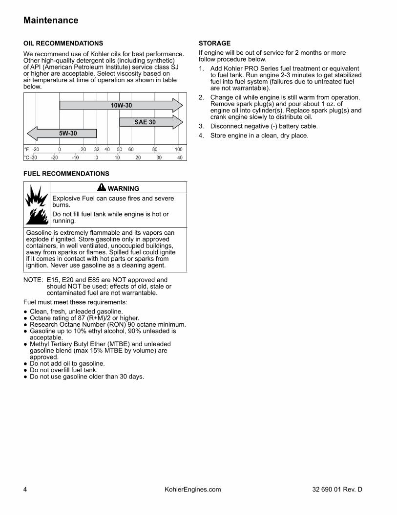
OIL RECOMMENDATIONSWe recommend use of Kohler oils for best performance. Other high-quality detergent oils (including synthetic) of API (American Petroleum Institute) service class SJ or higher are acceptable. Select viscosity based on air temperature at time of operation as shown in table below.
FUEL RECOMMENDATIONS
WARNINGExplosive Fuel can cause fires and severe burns.Do not fill fuel tank while engine is hot or running.
Gasoline is extremely flammable and its vapors can explode if ignited. Store gasoline only in approved containers, in well ventilated, unoccupied buildings, away from sparks or flames. Spilled fuel could ignite if it comes in contact with hot parts or sparks from ignition. Never use gasoline as a cleaning agent.
NOTE: E15, E20 and E85 are NOT approved and should NOT be used; effects of old, stale or contaminated fuel are not warrantable.
Fuel must meet these requirements:● Clean, fresh, unleaded gasoline.● Octane rating of 87 (R+M)/2 or higher.● Research Octane Number (RON) 90 octane minimum.● Gasoline up to 10% ethyl alcohol, 90% unleaded is
acceptable.● Methyl Tertiary Butyl Ether (MTBE) and unleaded
gasoline blend (max 15% MTBE by volume) are approved.
● Do not add oil to gasoline.● Do not overfill fuel tank.● Do not use gasoline older than 30 days.
STORAGEIf engine will be out of service for 2 months or more follow procedure below.1. Add Kohler PRO Series fuel treatment or equivalent
to fuel tank. Run engine 2-3 minutes to get stabilized fuel into fuel system (failures due to untreated fuel are not warrantable).
2. Change oil while engine is still warm from operation. Remove spark plug(s) and pour about 1 oz. of engine oil into cylinder(s). Replace spark plug(s) and crank engine slowly to distribute oil.
3. Disconnect negative (-) battery cable.4. Store engine in a clean, dry place.
5
Specifications
32 690 01 Rev. D KohlerEngines.com
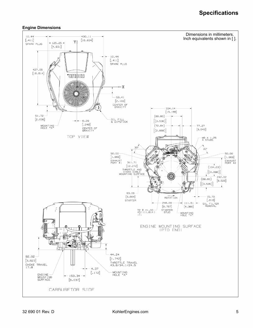
Dimensions in millimeters.Inch equivalents shown in [ ].
Engine Dimensions
6
Specifications
KohlerEngines.com 32 690 01 Rev. D
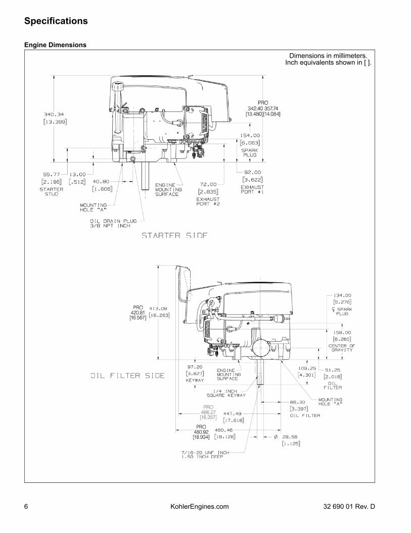
Dimensions in millimeters.Inch equivalents shown in [ ].
Engine Dimensions
7
Specifications
32 690 01 Rev. D KohlerEngines.com
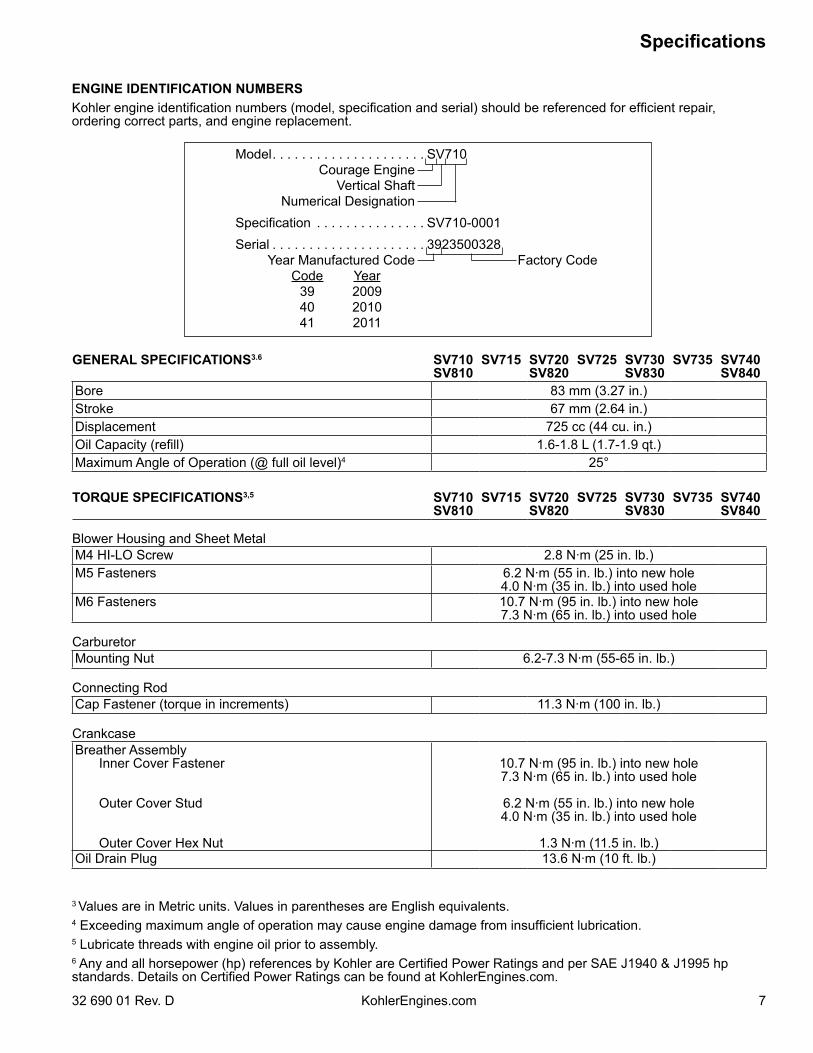
GENERAL SPECIFICATIONS3.6 SV710SV810
SV715 SV720SV820
SV725 SV730SV830
SV735 SV740SV840
Bore 83 mm (3.27 in.)Stroke 67 mm (2.64 in.)Displacement 725 cc (44 cu. in.)Oil Capacity (refill) 1.6-1.8 L (1.7-1.9 qt.)Maximum Angle of Operation (@ full oil level)4 25°
TORQUE SPECIFICATIONS3,5 SV710SV810
SV715 SV720SV820
SV725 SV730SV830
SV735 SV740SV840
Blower Housing and Sheet MetalM4 HI-LO Screw 2.8 N·m (25 in. lb.)M5 Fasteners 6.2 N·m (55 in. lb.) into new hole
4.0 N·m (35 in. lb.) into used holeM6 Fasteners 10.7 N·m (95 in. lb.) into new hole
7.3 N·m (65 in. lb.) into used hole
CarburetorMounting Nut 6.2-7.3 N·m (55-65 in. lb.)
Connecting RodCap Fastener (torque in increments) 11.3 N·m (100 in. lb.)
CrankcaseBreather Assembly Inner Cover Fastener
Outer Cover Stud
Outer Cover Hex Nut
10.7 N·m (95 in. lb.) into new hole7.3 N·m (65 in. lb.) into used hole
6.2 N·m (55 in. lb.) into new hole4.0 N·m (35 in. lb.) into used hole
1.3 N·m (11.5 in. lb.)Oil Drain Plug 13.6 N·m (10 ft. lb.)
ENGINE IDENTIFICATION NUMBERSKohler engine identification numbers (model, specification and serial) should be referenced for efficient repair, ordering correct parts, and engine replacement.
Model . . . . . . . . . . . . . . . . . . . . . SV710Courage Engine
Vertical ShaftNumerical Designation
Specification . . . . . . . . . . . . . . . SV710-0001Serial . . . . . . . . . . . . . . . . . . . . . 3923500328
Year Manufactured Code Factory Code Code Year 39 2009 40 2010 41 2011
3 Values are in Metric units. Values in parentheses are English equivalents. 4 Exceeding maximum angle of operation may cause engine damage from insufficient lubrication.5 Lubricate threads with engine oil prior to assembly.6 Any and all horsepower (hp) references by Kohler are Certified Power Ratings and per SAE J1940 & J1995 hp standards. Details on Certified Power Ratings can be found at KohlerEngines.com.
8
Specifications
KohlerEngines.com 32 690 01 Rev. D
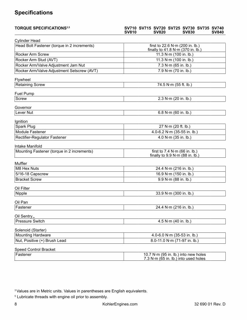
TORQUE SPECIFICATIONS3,5 SV710SV810
SV715 SV720SV820
SV725 SV730SV830
SV735 SV740SV840
Cylinder HeadHead Bolt Fastener (torque in 2 increments) first to 22.6 N·m (200 in. lb.)
finally to 41.8 N·m (370 in. lb.)Rocker Arm Screw 11.3 N·m (100 in. lb.)Rocker Arm Stud (AVT) 11.3 N·m (100 in. lb.)Rocker Arm/Valve Adjustment Jam Nut 7.3 N·m (65 in. lb.)Rocker Arm/Valve Adjustment Setscrew (AVT) 7.9 N·m (70 in. lb.)
FlywheelRetaining Screw 74.5 N·m (55 ft. lb.)
Fuel PumpScrew 2.3 N·m (20 in. lb.)
GovernorLever Nut 6.8 N·m (60 in. lb.)
IgnitionSpark Plug 27 N·m (20 ft. lb.)Module Fastener 4.0-6.2 N·m (35-55 in. lb.)Rectifier-Regulator Fastener 4.0 N·m (35 in. lb.)
Intake ManifoldMounting Fastener (torque in 2 increments) first to 7.4 N·m (66 in. lb.)
finally to 9.9 N·m (88 in. lb.)
MufflerM8 Hex Nuts 24.4 N·m (216 in. lb.)5/16-18 Capscrew 16.9 N·m (150 in. lb.)Bracket Screw 9.9 N·m (88 in. lb.)
Oil FilterNipple 33.9 N·m (300 in. lb.)
Oil PanFastener 24.4 N·m (216 in. lb.)
Oil Sentry™Pressure Switch 4.5 N·m (40 in. lb.)
Solenoid (Starter)Mounting Hardware 4.0-6.0 N·m (35-53 in. lb.)Nut, Positive (+) Brush Lead 8.0-11.0 N·m (71-97 in. lb.)
Speed Control BracketFastener 10.7 N·m (95 in. lb.) into new holes
7.3 N·m (65 in. lb.) into used holes
3 Values are in Metric units. Values in parentheses are English equivalents. 5 Lubricate threads with engine oil prior to assembly.
9
Specifications
32 690 01 Rev. D KohlerEngines.com
TORQUE SPECIFICATIONS3,5 SV710SV810
SV715 SV720SV820
SV725 SV730SV830
SV735 SV740SV840
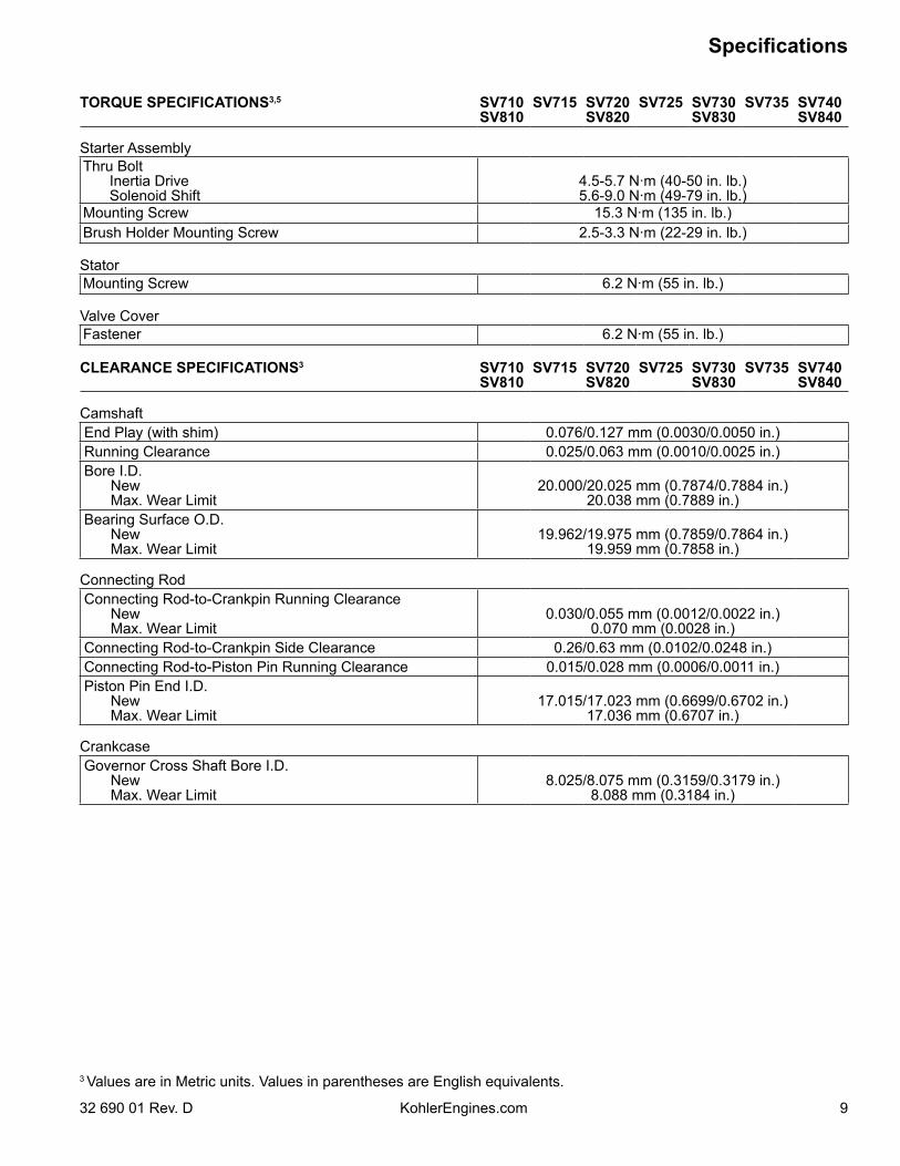
Starter AssemblyThru Bolt Inertia Drive Solenoid Shift
4.5-5.7 N·m (40-50 in. lb.)5.6-9.0 N·m (49-79 in. lb.)
Mounting Screw 15.3 N·m (135 in. lb.)Brush Holder Mounting Screw 2.5-3.3 N·m (22-29 in. lb.)
StatorMounting Screw 6.2 N·m (55 in. lb.)
Valve CoverFastener 6.2 N·m (55 in. lb.)
CLEARANCE SPECIFICATIONS3 SV710SV810
SV715 SV720SV820
SV725 SV730SV830
SV735 SV740SV840
CamshaftEnd Play (with shim) 0.076/0.127 mm (0.0030/0.0050 in.)Running Clearance 0.025/0.063 mm (0.0010/0.0025 in.)Bore I.D. New Max. Wear Limit
20.000/20.025 mm (0.7874/0.7884 in.)20.038 mm (0.7889 in.)
Bearing Surface O.D. New Max. Wear Limit
19.962/19.975 mm (0.7859/0.7864 in.)19.959 mm (0.7858 in.)
Connecting RodConnecting Rod-to-Crankpin Running Clearance New Max. Wear Limit
0.030/0.055 mm (0.0012/0.0022 in.)0.070 mm (0.0028 in.)
Connecting Rod-to-Crankpin Side Clearance 0.26/0.63 mm (0.0102/0.0248 in.)Connecting Rod-to-Piston Pin Running Clearance 0.015/0.028 mm (0.0006/0.0011 in.)Piston Pin End I.D. New Max. Wear Limit
17.015/17.023 mm (0.6699/0.6702 in.)17.036 mm (0.6707 in.)
CrankcaseGovernor Cross Shaft Bore I.D. New Max. Wear Limit
8.025/8.075 mm (0.3159/0.3179 in.)8.088 mm (0.3184 in.)
3 Values are in Metric units. Values in parentheses are English equivalents.
10
Specifications
KohlerEngines.com 32 690 01 Rev. D
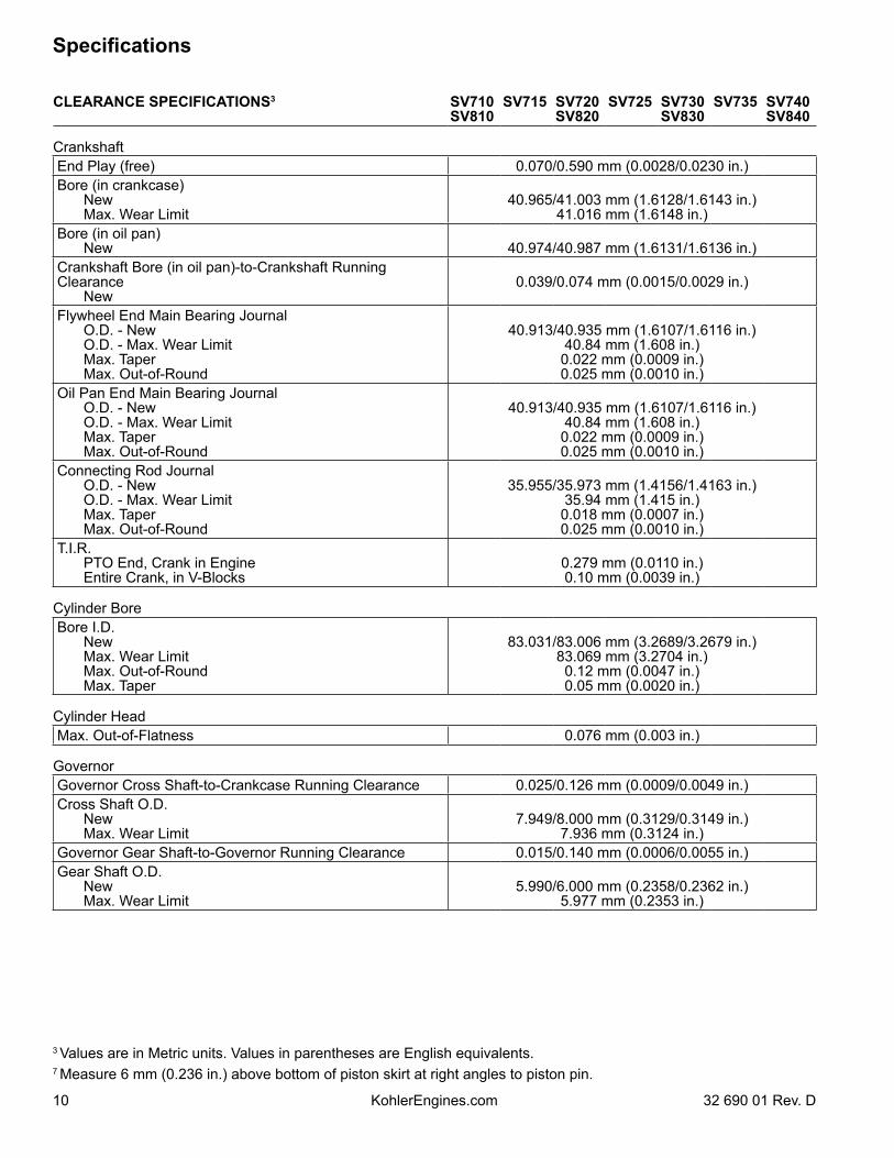
CLEARANCE SPECIFICATIONS3 SV710SV810
SV715 SV720SV820
SV725 SV730SV830
SV735 SV740SV840
CrankshaftEnd Play (free) 0.070/0.590 mm (0.0028/0.0230 in.)Bore (in crankcase) New Max. Wear Limit
40.965/41.003 mm (1.6128/1.6143 in.)41.016 mm (1.6148 in.)
Bore (in oil pan) New 40.974/40.987 mm (1.6131/1.6136 in.)Crankshaft Bore (in oil pan)-to-Crankshaft Running Clearance New
0.039/0.074 mm (0.0015/0.0029 in.)
Flywheel End Main Bearing Journal O.D. - New O.D. - Max. Wear Limit Max. Taper Max. Out-of-Round
40.913/40.935 mm (1.6107/1.6116 in.)40.84 mm (1.608 in.)0.022 mm (0.0009 in.)0.025 mm (0.0010 in.)
Oil Pan End Main Bearing Journal O.D. - New O.D. - Max. Wear Limit Max. Taper Max. Out-of-Round
40.913/40.935 mm (1.6107/1.6116 in.)40.84 mm (1.608 in.)0.022 mm (0.0009 in.)0.025 mm (0.0010 in.)
Connecting Rod Journal O.D. - New O.D. - Max. Wear Limit Max. Taper Max. Out-of-Round
35.955/35.973 mm (1.4156/1.4163 in.)35.94 mm (1.415 in.)0.018 mm (0.0007 in.)0.025 mm (0.0010 in.)
T.I.R. PTO End, Crank in Engine Entire Crank, in V-Blocks
0.279 mm (0.0110 in.)0.10 mm (0.0039 in.)
Cylinder BoreBore I.D. New Max. Wear Limit Max. Out-of-Round Max. Taper
83.031/83.006 mm (3.2689/3.2679 in.)83.069 mm (3.2704 in.)0.12 mm (0.0047 in.)0.05 mm (0.0020 in.)
Cylinder HeadMax. Out-of-Flatness 0.076 mm (0.003 in.)
GovernorGovernor Cross Shaft-to-Crankcase Running Clearance 0.025/0.126 mm (0.0009/0.0049 in.)Cross Shaft O.D. New Max. Wear Limit
7.949/8.000 mm (0.3129/0.3149 in.)7.936 mm (0.3124 in.)
Governor Gear Shaft-to-Governor Running Clearance 0.015/0.140 mm (0.0006/0.0055 in.)Gear Shaft O.D. New Max. Wear Limit
5.990/6.000 mm (0.2358/0.2362 in.)5.977 mm (0.2353 in.)
3 Values are in Metric units. Values in parentheses are English equivalents.7 Measure 6 mm (0.236 in.) above bottom of piston skirt at right angles to piston pin.
11
Specifications
32 690 01 Rev. D KohlerEngines.com
CLEARANCE SPECIFICATIONS3 SV710SV810
SV715 SV720SV820
SV725 SV730SV830
SV735 SV740SV840
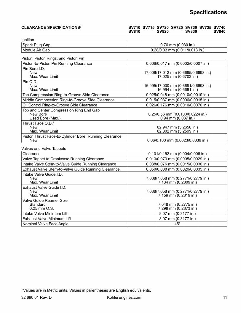
IgnitionSpark Plug Gap 0.76 mm (0.030 in.)Module Air Gap 0.28/0.33 mm (0.011/0.013 in.)
Piston, Piston Rings, and Piston PinPiston-to-Piston Pin Running Clearance 0.006/0.017 mm (0.0002/0.0007 in.)Pin Bore I.D. New Max. Wear Limit
17.006/17.012 mm (0.6695/0.6698 in.)17.025 mm (0.6703 in.)
Pin O.D. New Max. Wear Limit
16.995/17.000 mm (0.6691/0.6693 in.)16.994 mm (0.6691 in.)
Top Compression Ring-to-Groove Side Clearance 0.025/0.048 mm (0.0010/0.0019 in.)Middle Compression Ring-to-Groove Side Clearance 0.015/0.037 mm (0.0006/0.0015 in.)Oil Control Ring-to-Groove Side Clearance 0.026/0.176 mm (0.0010/0.0070 in.)Top and Center Compression Ring End Gap New Bore Used Bore (Max.)
0.25/0.56 mm (0.0100/0.0224 in.)0.94 mm (0.037 in.)
Thrust Face O.D.7
New Max. Wear Limit
82.947 mm (3.2656 in.)82.802 mm (3.2599 in.)
Piston Thrust Face-to-Cylinder Bore7 Running Clearance New 0.06/0.100 mm (0.0023/0.0039 in.)
Valves and Valve TappetsClearance 0.101/0.152 mm (0.004/0.006 in.)Valve Tappet to Crankcase Running Clearance 0.013/0.073 mm (0.0005/0.0029 in.)Intake Valve Stem-to-Valve Guide Running Clearance 0.038/0.076 mm (0.0015/0.0030 in.)Exhaust Valve Stem-to-Valve Guide Running Clearance 0.050/0.088 mm (0.0020/0.0035 in.)Intake Valve Guide I.D. New Max. Wear Limit
7.038/7.058 mm (0.2771/0.2779 in.)7.134 mm (0.2809 in.)
Exhaust Valve Guide I.D. New Max. Wear Limit
7.038/7.058 mm (0.2771/0.2779 in.)7.159 mm (0.2819 in.)
Valve Guide Reamer Size Standard 0.25 mm O.S.
7.048 mm (0.2775 in.)7.298 mm (0.2873 in.)
Intake Valve Minimum Lift 8.07 mm (0.3177 in.)Exhaust Valve Minimum Lift 8.07 mm (0.3177 in.)Nominal Valve Face Angle 45°
3 Values are in Metric units. Values in parentheses are English equivalents.
12
Specifications
KohlerEngines.com 32 690 01 Rev. D
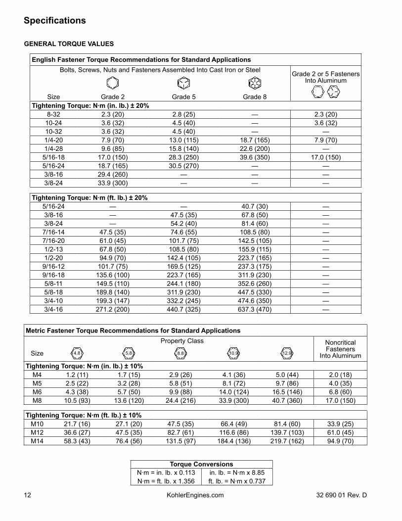
GENERAL TORQUE VALUES
Metric Fastener Torque Recommendations for Standard ApplicationsProperty Class Noncritical
Fasteners Into AluminumSize 4.8 5.8 8.8 10.9 12.9
Tightening Torque: N·m (in. lb.) ± 10%M4 1.2 (11) 1.7 (15) 2.9 (26) 4.1 (36) 5.0 (44) 2.0 (18)M5 2.5 (22) 3.2 (28) 5.8 (51) 8.1 (72) 9.7 (86) 4.0 (35)M6 4.3 (38) 5.7 (50) 9.9 (88) 14.0 (124) 16.5 (146) 6.8 (60)M8 10.5 (93) 13.6 (120) 24.4 (216) 33.9 (300) 40.7 (360) 17.0 (150)
Tightening Torque: N·m (ft. lb.) ± 10%M10 21.7 (16) 27.1 (20) 47.5 (35) 66.4 (49) 81.4 (60) 33.9 (25)M12 36.6 (27) 47.5 (35) 82.7 (61) 116.6 (86) 139.7 (103) 61.0 (45)M14 58.3 (43) 76.4 (56) 131.5 (97) 184.4 (136) 219.7 (162) 94.9 (70)
Torque ConversionsN·m = in. lb. x 0.113 in. lb. = N·m x 8.85N·m = ft. lb. x 1.356 ft. lb. = N·m x 0.737
English Fastener Torque Recommendations for Standard ApplicationsBolts, Screws, Nuts and Fasteners Assembled Into Cast Iron or Steel Grade 2 or 5 Fasteners
Into Aluminum
Size Grade 2 Grade 5 Grade 8Tightening Torque: N·m (in. lb.) ± 20%
8-32 2.3 (20) 2.8 (25) — 2.3 (20)10-24 3.6 (32) 4.5 (40) — 3.6 (32)10-32 3.6 (32) 4.5 (40) — —1/4-20 7.9 (70) 13.0 (115) 18.7 (165) 7.9 (70)1/4-28 9.6 (85) 15.8 (140) 22.6 (200) —5/16-18 17.0 (150) 28.3 (250) 39.6 (350) 17.0 (150)5/16-24 18.7 (165) 30.5 (270) — —3/8-16 29.4 (260) — — —3/8-24 33.9 (300) — — —
Tightening Torque: N·m (ft. lb.) ± 20%5/16-24 — — 40.7 (30) —3/8-16 — 47.5 (35) 67.8 (50) —3/8-24 — 54.2 (40) 81.4 (60) —
7/16-14 47.5 (35) 74.6 (55) 108.5 (80) —7/16-20 61.0 (45) 101.7 (75) 142.5 (105) —1/2-13 67.8 (50) 108.5 (80) 155.9 (115) —1/2-20 94.9 (70) 142.4 (105) 223.7 (165) —
9/16-12 101.7 (75) 169.5 (125) 237.3 (175) —9/16-18 135.6 (100) 223.7 (165) 311.9 (230) —5/8-11 149.5 (110) 244.1 (180) 352.6 (260) —5/8-18 189.8 (140) 311.9 (230) 447.5 (330) —3/4-10 199.3 (147) 332.2 (245) 474.6 (350) —3/4-16 271.2 (200) 440.7 (325) 637.3 (470) —
Tools and Aids
1332 690 01 Rev. D KohlerEngines.com
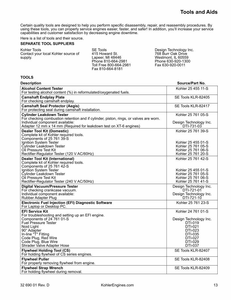
Certain quality tools are designed to help you perform specific disassembly, repair, and reassembly procedures. By using these tools, you can properly service engines easier, faster, and safer! In addition, you’ll increase your service capabilities and customer satisfaction by decreasing engine downtime.Here is a list of tools and their source.SEPARATE TOOL SUPPLIERSKohler Tools Contact your local Kohler source of supply.
SE Tools 415 Howard St. Lapeer, MI 48446 Phone 810-664-2981 Toll Free 800-664-2981 Fax 810-664-8181
Design Technology Inc. 768 Burr Oak Drive Westmont, IL 60559 Phone 630-920-1300 Fax 630-920-0011
TOOLSDescription Source/Part No.Alcohol Content TesterFor testing alcohol content (%) in reformulated/oxygenated fuels.
Kohler 25 455 11-S
Camshaft Endplay PlateFor checking camshaft endplay.
SE Tools KLR-82405
Camshaft Seal Protector (Aegis)For protecting seal during camshaft installation.
SE Tools KLR-82417
Cylinder Leakdown TesterFor checking combustion retention and if cylinder, piston, rings, or valves are worn.Individual component available:Adapter 12 mm x 14 mm (Required for leakdown test on XT-6 engines)
Kohler 25 761 05-S
Design Technology Inc.DTI-731-03
Dealer Tool Kit (Domestic)Complete kit of Kohler required tools.Components of 25 761 39-SIgnition System TesterCylinder Leakdown TesterOil Pressure Test KitRectifier-Regulator Tester (120 V AC/60Hz)
Kohler 25 761 39-S
Kohler 25 455 01-SKohler 25 761 05-SKohler 25 761 06-SKohler 25 761 20-S
Dealer Tool Kit (International)Complete kit of Kohler required tools.Components of 25 761 42-SIgnition System TesterCylinder Leakdown TesterOil Pressure Test KitRectifier-Regulator Tester (240 V AC/50Hz)
Kohler 25 761 42-S
Kohler 25 455 01-SKohler 25 761 05-SKohler 25 761 06-SKohler 25 761 41-S
Digital Vacuum/Pressure TesterFor checking crankcase vacuum.Individual component available:Rubber Adapter Plug
Design Technology Inc.DTI-721-01
Design Technology Inc.DTI-721-10
Electronic Fuel Injection (EFI) Diagnostic SoftwareFor Laptop or Desktop PC.
Kohler 25 761 23-S
EFI Service KitFor troubleshooting and setting up an EFI engine.Components of 24 761 01-SFuel Pressure TesterNoid Light90° AdapterIn-line "T" FittingCode Plug, Red WireCode Plug, Blue WireShrader Valve Adapter Hose
Kohler 24 761 01-S
Design Technology Inc.DTI-019DTI-021DTI-023DTI-035DTI-027DTI-029DTI-037
Flywheel Holding Tool (CS) For holding flywheel of CS series engines.
SE Tools KLR-82407
Flywheel PullerFor properly removing flywheel from engine.
SE Tools KLR-82408
Flywheel Strap WrenchFor holding flywheel during removal.
SE Tools KLR-82409
Tools and Aids
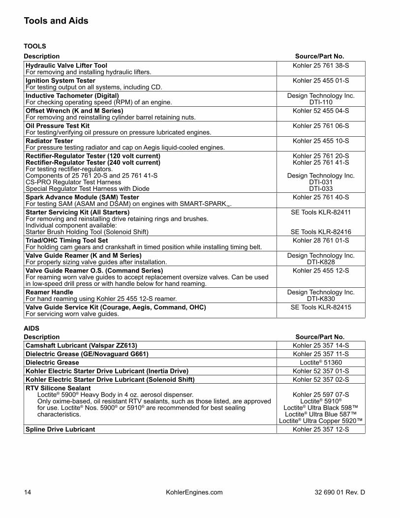
14 32 690 01 Rev. DKohlerEngines.com
TOOLSDescription Source/Part No.Hydraulic Valve Lifter ToolFor removing and installing hydraulic lifters.
Kohler 25 761 38-S
Ignition System TesterFor testing output on all systems, including CD.
Kohler 25 455 01-S
Inductive Tachometer (Digital)For checking operating speed (RPM) of an engine.
Design Technology Inc.DTI-110
Offset Wrench (K and M Series) For removing and reinstalling cylinder barrel retaining nuts.
Kohler 52 455 04-S
Oil Pressure Test KitFor testing/verifying oil pressure on pressure lubricated engines.
Kohler 25 761 06-S
Radiator TesterFor pressure testing radiator and cap on Aegis liquid-cooled engines.
Kohler 25 455 10-S
Rectifier-Regulator Tester (120 volt current)Rectifier-Regulator Tester (240 volt current)For testing rectifier-regulators.Components of 25 761 20-S and 25 761 41-SCS-PRO Regulator Test HarnessSpecial Regulator Test Harness with Diode
Kohler 25 761 20-SKohler 25 761 41-S
Design Technology Inc.DTI-031DTI-033
Spark Advance Module (SAM) TesterFor testing SAM (ASAM and DSAM) on engines with SMART-SPARK™.
Kohler 25 761 40-S
Starter Servicing Kit (All Starters)For removing and reinstalling drive retaining rings and brushes.Individual component available:Starter Brush Holding Tool (Solenoid Shift)
SE Tools KLR-82411
SE Tools KLR-82416Triad/OHC Timing Tool SetFor holding cam gears and crankshaft in timed position while installing timing belt.
Kohler 28 761 01-S
Valve Guide Reamer (K and M Series)For properly sizing valve guides after installation.
Design Technology Inc.DTI-K828
Valve Guide Reamer O.S. (Command Series)For reaming worn valve guides to accept replacement oversize valves. Can be used in low-speed drill press or with handle below for hand reaming.
Kohler 25 455 12-S
Reamer HandleFor hand reaming using Kohler 25 455 12-S reamer.
Design Technology Inc.DTI-K830
Valve Guide Service Kit (Courage, Aegis, Command, OHC)For servicing worn valve guides.
SE Tools KLR-82415
AIDSDescription Source/Part No.Camshaft Lubricant (Valspar ZZ613) Kohler 25 357 14-SDielectric Grease (GE/Novaguard G661) Kohler 25 357 11-SDielectric Grease Loctite® 51360Kohler Electric Starter Drive Lubricant (Inertia Drive) Kohler 52 357 01-SKohler Electric Starter Drive Lubricant (Solenoid Shift) Kohler 52 357 02-SRTV Silicone Sealant Loctite® 5900® Heavy Body in 4 oz. aerosol dispenser. Only oxime-based, oil resistant RTV sealants, such as those listed, are approved
for use. Loctite® Nos. 5900® or 5910® are recommended for best sealing characteristics.
Kohler 25 597 07-SLoctite® 5910®
Loctite® Ultra Black 598™Loctite® Ultra Blue 587™
Loctite® Ultra Copper 5920™Spline Drive Lubricant Kohler 25 357 12-S
Tools and Aids
1532 690 01 Rev. D KohlerEngines.com
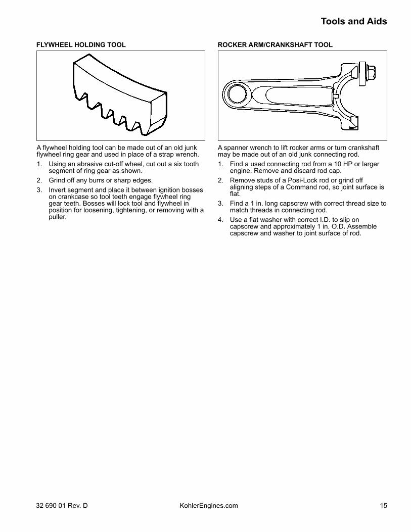
FLYWHEEL HOLDING TOOL ROCKER ARM/CRANKSHAFT TOOL
A flywheel holding tool can be made out of an old junk flywheel ring gear and used in place of a strap wrench.1. Using an abrasive cut-off wheel, cut out a six tooth
segment of ring gear as shown.2. Grind off any burrs or sharp edges.3. Invert segment and place it between ignition bosses
on crankcase so tool teeth engage flywheel ring gear teeth. Bosses will lock tool and flywheel in position for loosening, tightening, or removing with a puller.
A spanner wrench to lift rocker arms or turn crankshaft may be made out of an old junk connecting rod.1. Find a used connecting rod from a 10 HP or larger
engine. Remove and discard rod cap.2. Remove studs of a Posi-Lock rod or grind off
aligning steps of a Command rod, so joint surface is flat.
3. Find a 1 in. long capscrew with correct thread size to match threads in connecting rod.
4. Use a flat washer with correct I.D. to slip on capscrew and approximately 1 in. O.D. Assemble capscrew and washer to joint surface of rod.
Troubleshooting
16 32 690 01 Rev. DKohlerEngines.com
Engine Cranks But Will Not Start● Battery connected backwards.● Blown fuse.● Carburetor solenoid malfunction.● Choke not closing.● Clogged fuel line or fuel filter.● Diode in wiring harness failed in open circuit mode.● DSAI or DSAM malfunction.● Empty fuel tank.● Faulty electronic control unit.● Faulty ignition coil(s).● Faulty spark plug(s).● Fuel pump malfunction-vacuum hose clogged or
leaking.● Fuel shut-off valve closed.● Ignition module(s) faulty or improperly gapped.● Insufficient voltage to electronic control unit.● Interlock switch is engaged or faulty.● Key switch or kill switch in OFF position.● Low oil level.● Quality of fuel (dirt, water, stale, mixture).● SMART-SPARKTM malfunction.● Spark plug lead(s) disconnected.Engine Starts But Does Not Keep Running● Faulty carburetor.● Faulty cylinder head gasket.● Faulty or misadjusted choke or throttle controls.● Fuel pump malfunction-vacuum hose clogged or
leaking.● Intake system leak.● Loose wires or connections that intermittently ground
ignition kill circuit.● Quality of fuel (dirt, water, stale, mixture).● Restricted fuel tank cap vent.Engine Starts Hard● Clogged fuel line or fuel filter.● Engine overheated.● Faulty ACR mechanism.● Faulty or misadjusted choke or throttle controls.● Faulty spark plug(s).● Flywheel key sheared.● Fuel pump malfunction-vacuum hose clogged or
leaking.● Interlock switch is engaged or faulty.● Loose wires or connections that intermittently ground
ignition kill circuit.● Low compression.● Quality of fuel (dirt, water, stale, mixture).● Weak spark.
TROUBLESHOOTING GUIDEWhen troubles occur, be sure to check simple causes which, at first, may seem too obvious to be considered. For example, a starting problem could be caused by an empty fuel tank.Some general common causes of engine troubles are listed below and vary by engine specification. Use these to locate causing factors.
Engine Will Not Crank● Battery is discharged.● Faulty electric starter or solenoid.● Faulty key switch or ignition switch.● Interlock switch is engaged or faulty.● Loose wires or connections that intermittently ground
ignition kill circuit.● Pawls not engaging in drive cup.● Seized internal engine components.Engine Runs But Misses● Carburetor adjusted incorrectly.● Engine overheated.● Faulty spark plug(s).● Ignition module(s) faulty or improperly gapped.● Incorrect crankshaft position sensor air gap.● Interlock switch is engaged or faulty.● Loose wires or connections that intermittently ground
ignition kill circuit.● Quality of fuel (dirt, water, stale, mixture).● Spark plug lead(s) disconnected.● Spark plug lead boot loose on plug.● Spark plug lead loose.Engine Will Not Idle● Engine overheated.● Faulty spark plug(s).● Idle fuel adjusting needle(s) improperly set.● Idle speed adjusting screw improperly set.● Inadequate fuel supply.● Low compression.● Quality of fuel (dirt, water, stale, mixture).● Restricted fuel tank cap vent.Engine Overheats● Cooling fan broken.● Excessive engine load.● Fan belt failed/off.● Faulty carburetor.● High crankcase oil level.● Lean fuel mixture.● Low cooling system fluid level.● Low crankcase oil level.● Radiator, and/or cooling system components clogged,
restricted, or leaking.● Water pump belt failed/broken.● Water pump malfunction.Engine Knocks● Excessive engine load.● Hydraulic lifter malfunction.● Incorrect oil viscosity/type.● Internal wear or damage.● Low crankcase oil level.● Quality of fuel (dirt, water, stale, mixture).
1732 690 01 Rev. D KohlerEngines.com
Troubleshooting
Engine Loses Power● Dirty air cleaner element.● Engine overheated.● Excessive engine load.● Restricted exhaust.● Faulty spark plug(s).● High crankcase oil level.● Incorrect governor setting.● Low battery.● Low compression.● Low crankcase oil level.● Quality of fuel (dirt, water, stale, mixture).Engine Uses Excessive Amount of Oil● Loose or improperly torqued fasteners.● Blown head gasket/overheated.● Breather reed broken.● Clogged, broken, or inoperative crankcase breather.● Crankcase overfilled.● Incorrect oil viscosity/type.● Worn cylinder bore.● Worn or broken piston rings.● Worn valve stems/valve guides.Oil Leaks from Oil Seals, Gaskets● Breather reed broken.● Clogged, broken, or inoperative crankcase breather.● Loose or improperly torqued fasteners.● Piston blow by, or leaky valves.● Restricted exhaust.
EXTERNAL ENGINE INSPECTIONNOTE: It is good practice to drain oil at a location away
from workbench. Be sure to allow ample time for complete drainage.
Before cleaning or disassembling engine, make a thorough inspection of its external appearance and condition. This inspection can give clues to what might be found inside engines (and cause) when it is disassembled.● Check for buildup of dirt and debris on crankcase,
cooling fins, grass screen, and other external surfaces. Dirt or debris on these areas can cause overheating.
● Check for obvious fuel and oil leaks, and damaged components. Excessive oil leakage can indicate a clogged or inoperative breather, worn or damaged seals or gaskets, or loose fasteners.
● Check air cleaner cover and base for damage or indications of improper fit and seal.
● Check air cleaner element. Look for holes, tears, cracked or damaged sealing surfaces, or other damage that could allow unfiltered air into engine. A dirty or clogged element could indicate insufficient or improper maintenance.
● Check carburetor throat for dirt. Dirt in throat is further indication that air cleaner was not functioning properly.
● Check if oil level is within operating range on dipstick. If it is above, sniff for gasoline odor.
● Check condition of oil. Drain oil into a container; it should flow freely. Check for metal chips and other foreign particles.
Sludge is a natural by-product of combustion; a small accumulation is normal. Excessive sludge formation could indicate over rich fuel settings, weak ignition, overextended oil change interval or wrong weight or type of oil was used.
CLEANING ENGINE
WARNINGCleaning Solvents can cause severe injury or death.Use only in well ventilated areas away from ignition sources.
Carburetor cleaners and solvents are extremely flammable. Follow cleaner manufacturer’s warnings and instructions on its proper and safe use. Never use gasoline as a cleaning agent.
After inspecting external condition of engine, clean engine thoroughly before disassembly. Clean individual components as engine is disassembled. Only clean parts can be accurately inspected and gauged for wear or damage. There are many commercially available cleaners that will quickly remove grease, oil, and grime from engine parts. When such a cleaner is used, follow manufacturer’s instructions and safety precautions carefully.Make sure all traces of cleaner are removed before engine is reassembled and placed into operation. Even small amounts of these cleaners can quickly break down lubricating properties of engine oil.
Troubleshooting
18 32 690 01 Rev. DKohlerEngines.com
Condition ConclusionCrankcase breather clogged or inoperative. NOTE: If breather is integral part of valve cover and
cannot be serviced separately, replace valve cover and recheck pressure.
Disassemble breather, clean parts thoroughly, check sealing surfaces for flatness, reassemble, and recheck pressure.
Seals and/or gaskets leaking. Loose or improperly torque fasteners.
Replace all worn or damaged seals and gaskets. Make sure all fasteners are tightened securely. Use appropriate torque valves and sequences when necessary.
Piston blow by or leaky valves (confirm by inspecting components).
Recondition piston, rings, cylinder bore, valves and valves guides.
Restricted exhaust. Check exhaust screen/spark arrestor (if equipped). Clean or replace as needed. Repair or replace any other damaged/restricted muffler or exhaust system parts.
CRANKCASE VACUUM TEST
WARNING
Carbon Monoxide can cause severe nausea, fainting or death.Avoid inhaling exhaust fumes.
Engine exhaust gases contain poisonous carbon monoxide. Carbon monoxide is odorless, colorless, and can cause death if inhaled.
To test crankcase vacuum with manometer:1. Insert rubber stopper into oil fill hole. Be sure pinch
clamp is installed on hose and use tapered adapters to connect hose between stopper and one manometer tube. Leave other tube open to atmosphere. Check that water level in manometer is at 0 line. Make sure pinch clamp is closed.
2. Start engine and run no-load high speed.3. Open clamp and note water level in tube. Level in engine side should be a minimum of 10.2
cm (4 in.) above level in open side. If level in engine side is less than specified (low/no
vacuum), or level in engine side is lower than level in open side (pressure), check for conditions in table below.
4. Close pinch clamp before stopping engine.
To test crankcase vacuum with vacuum/pressure gauge:1. Remove dipstick or oil fill plug/cap.2. Install adapter into oil fill//dipstick tube opening,
upside down over end of a small diameter dipstick tube, or directly into engine if a tube is not used. Insert barbed gauge fitting into hole in stopper.
3. Run engine and observe gauge reading. Analog tester–needle movement to left of 0 is a
vacuum, and movement to right indicates a pressure. Digital tester–depress test button on top of tester. Crankcase vacuum should be a minimum of 10.2 cm
(4 in.) of water. If reading is below specification, or if pressure is present, check table below for possible causes and conclusions.
WARNING
Rotating Parts can cause severe injury.Stay away while engine is in operation.
Keep hands, feet, hair, and clothing away from all moving parts to prevent injury. Never operate engine with covers, shrouds, or guards removed.
A partial vacuum should be present in crankcase when engine is operating. Pressure in crankcase (normally caused by a clogged or improperly assembled breather) can cause oil to be forced out at oil seals, gaskets, or other available spots.Crankcase vacuum is best measured with either a water manometer or a vacuum gauge. Complete instructions are provided in kits.
1932 690 01 Rev. D KohlerEngines.com
Troubleshooting
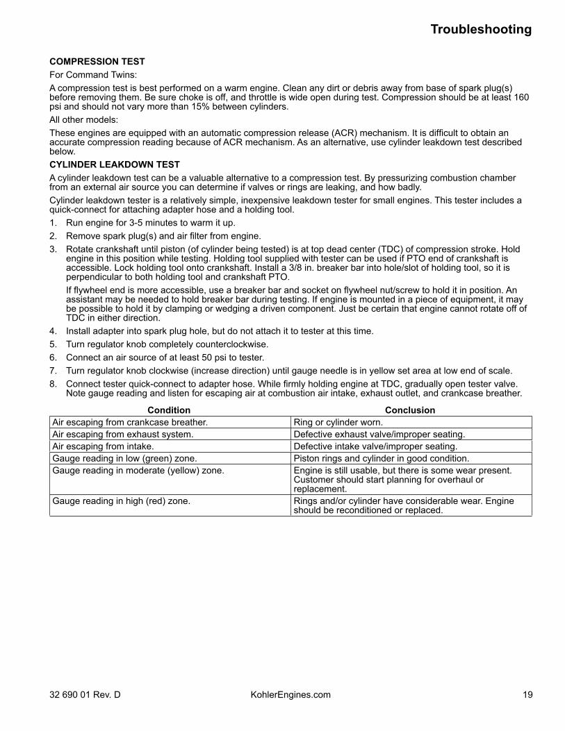
COMPRESSION TESTFor Command Twins:A compression test is best performed on a warm engine. Clean any dirt or debris away from base of spark plug(s) before removing them. Be sure choke is off, and throttle is wide open during test. Compression should be at least 160 psi and should not vary more than 15% between cylinders.All other models:These engines are equipped with an automatic compression release (ACR) mechanism. It is difficult to obtain an accurate compression reading because of ACR mechanism. As an alternative, use cylinder leakdown test described below.CYLINDER LEAKDOWN TESTA cylinder leakdown test can be a valuable alternative to a compression test. By pressurizing combustion chamber from an external air source you can determine if valves or rings are leaking, and how badly.Cylinder leakdown tester is a relatively simple, inexpensive leakdown tester for small engines. This tester includes a quick-connect for attaching adapter hose and a holding tool.1. Run engine for 3-5 minutes to warm it up.2. Remove spark plug(s) and air filter from engine.3. Rotate crankshaft until piston (of cylinder being tested) is at top dead center (TDC) of compression stroke. Hold
engine in this position while testing. Holding tool supplied with tester can be used if PTO end of crankshaft is accessible. Lock holding tool onto crankshaft. Install a 3/8 in. breaker bar into hole/slot of holding tool, so it is perpendicular to both holding tool and crankshaft PTO.
If flywheel end is more accessible, use a breaker bar and socket on flywheel nut/screw to hold it in position. An assistant may be needed to hold breaker bar during testing. If engine is mounted in a piece of equipment, it may be possible to hold it by clamping or wedging a driven component. Just be certain that engine cannot rotate off of TDC in either direction.
4. Install adapter into spark plug hole, but do not attach it to tester at this time.5. Turn regulator knob completely counterclockwise.6. Connect an air source of at least 50 psi to tester.7. Turn regulator knob clockwise (increase direction) until gauge needle is in yellow set area at low end of scale.8. Connect tester quick-connect to adapter hose. While firmly holding engine at TDC, gradually open tester valve.
Note gauge reading and listen for escaping air at combustion air intake, exhaust outlet, and crankcase breather.
Condition ConclusionAir escaping from crankcase breather. Ring or cylinder worn.Air escaping from exhaust system. Defective exhaust valve/improper seating.Air escaping from intake. Defective intake valve/improper seating.Gauge reading in low (green) zone. Piston rings and cylinder in good condition.Gauge reading in moderate (yellow) zone. Engine is still usable, but there is some wear present.
Customer should start planning for overhaul or replacement.
Gauge reading in high (red) zone. Rings and/or cylinder have considerable wear. Engine should be reconditioned or replaced.
20
Air Cleaner/Intake
KohlerEngines.com 32 690 01 Rev. D
Open air cleaner access door on blower housing and unhook latch.
Precleaner (if equipped)1. Remove precleaner.2. Replace or wash precleaner in warm water with
detergent. Rinse and allow to air dry.3. Saturate precleaner with new engine oil; squeeze
out excess oil.4. Reinstall precleaner over paper element.
Paper Element1. Remove element from base; service precleaner.
Discard element. 2. Install precleaner over new paper element and install
on base.Hook latch; close and secure access door.
Air Cleaner BaseDisassembly/ReassemblyIf air cleaner base requires removal, proceed as follows:1. Remove mounting screws for fuel pump (if
equipped), and blower housing.2. Raise or remove blower housing for access to air
cleaner base.3. Remove air cleaner components from base.4. Remove nuts securing air cleaner base onto
mounting studs.5. Disconnect breather hose from air cleaner base,
then remove base and gasket.6. Reverse procedure to reassemble components.
Torque nuts to 6.2-7.3 N·m (55-65 in. lb.). Torque blower housing screws to 4.0 N·m (35 in. lb.), and front HI-LO screws to 2.8 N·m (25 in. lb.).
BREATHER TUBEEnsure both ends of breather tube are properly connected.AIR COOLING
WARNINGHot Parts can cause severe burns.Do not touch engine while operating or just after stopping.
Never operate engine with heat shields or guards removed.
Proper cooling is essential. To prevent over heating, clean screens, cooling fins, and other external surfaces of engine. Avoid spraying water at wiring harness or any electrical components. Refer to Maintenance Schedule.
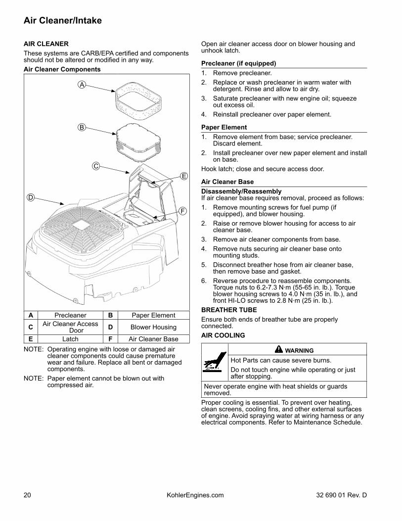
AIR CLEANERThese systems are CARB/EPA certified and components should not be altered or modified in any way.Air Cleaner Components
A Precleaner B Paper Element
C Air Cleaner Access Door D Blower Housing
E Latch F Air Cleaner Base
F
D
C
B
A
E
NOTE: Operating engine with loose or damaged air cleaner components could cause premature wear and failure. Replace all bent or damaged components.
NOTE: Paper element cannot be blown out with compressed air.
Fuel System
2132 690 01 Rev. D KohlerEngines.com
Typical carbureted fuel system and related components include:● Fuel tank.● Fuel lines.● In-line fuel filter.● Fuel pump.● Carburetor.
Fuel from tank is moved through in-line filter and fuel lines by fuel pump. Fuel then enters carburetor float bowl and is drawn into carburetor body and mixed with air. This fuel-air mixture is then burned in engine combustion chamber.FUEL RECOMMENDATIONSRefer to Maintenance.FUEL LINELow permeation fuel line must be installed on carbureted Kohler Co. engines to maintain EPA and CARB regulatory compliance. FUEL PUMPSome engines use a pulse style fuel pump. Pumping action of pulse style pumps is created by oscillation of positive and negative pressures within crankcase. This pressure is transmitted to pulse pump through rubber hose connected between pump and crankcase. Pumping action causes diaphragm on inside of pump to pull fuel in on its downward stroke and to push it into carburetor on its upward stroke. Two check valves prevent fuel from going backward through pump.
FUEL SYSTEM TESTSWhen engine starts hard or turns over but will not start, fuel system might be causing problems. Test fuel system by performing following test.
1. Check for fuel in combustion chamber. a. Disconnect and ground spark plug leads. b. Close choke on carburetor. c. Crank engine several times. d. Remove spark plug and check for fuel at tip.2. Check for fuel flow from tank to fuel pump. a. Remove fuel line from inlet fitting of fuel pump. b. Hold line below bottom of tank. Open shut-off
valve (if equipped) and observe flow.
PerformanceMinimum fuel delivery rate must be 7.5 L/hr. (2 gal./hr.) with a pressure at 0.3 psi and a fuel lift of 24 in. A 1.3 L/hr. (0.34 gal./hr.) fuel rate must be maintained at 5 Hz.
Fuel Pump ReplacementNOTE: Make sure orientation of new pump is consistent
with removed pump. Internal damage may occur if installed incorrectly.
To replace pulse pump follow these steps. Note orientation of pump before removing.1. Disconnect fuel lines from inlet, outlet, and pulse
fittings on fuel pump.2. Remove screws and take off pump.3. Connect pulse line to new fuel pump and make sure
opposite end is properly connected into valve cover.4. Attach new fuel pump using screws. Torque screws
to 2.3 N·m (20 in. lb.).5. Reconnect fuel lines to inlet and outlet fittings and
secure with clamps.
3. Check operation of fuel pump. a. Remove fuel line from inlet fitting of carburetor. b. Crank engine several times and observe flow.
Condition ConclusionFuel at tip of spark plug. Fuel is reaching combustion chamber.No fuel at tip of spark plug. Check fuel flow from fuel tank (step 2).Fuel flows from fuel line. Check for faulty fuel pump (step 3).
If fuel pump is working, check for faulty carburetor. Refer to Carburetor.
No fuel flow from fuel line. Check fuel tank cap vent, fuel pickup screen, in-line filter, shut-off valve, and fuel line. Correct any observed problem and reconnect line.
Fuel line condition. Check for a clogged fuel line. If fuel line is unobstructed, check for overfilled crankcase and/or oil in pulse line. If checks don't reveal cause of problem, replace pump.
Fuel System
22 32 690 01 Rev. DKohlerEngines.com
CARBURETOR
WARNINGExplosive Fuel can cause fires and severe burns.Do not fill fuel tank while engine is hot or running.
Gasoline is extremely flammable and its vapors can explode if ignited. Store gasoline only in approved containers, in well ventilated, unoccupied buildings, away from sparks or flames. Spilled fuel could ignite if it comes in contact with hot parts or sparks from ignition. Never use gasoline as a cleaning agent.
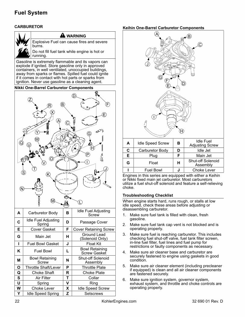
Nikki One-Barrel Carburetor Components
N
K
M L
I
PH
G
D
B
CA
X
RZ
WU
OV
TS
Q
Y
J
E
F
A Carburetor Body B Idle Fuel Adjusting Screw
C Idle Fuel Adjusting Spring D Passage Cover
E Cover Gasket F Cover Retaining Screw
G Main Jet H Ground Lead (Solenoid Only)
I Fuel Bowl Gasket J Float Kit
K Fuel Bowl L Bowl RetainingScrew Gasket
M Bowl Retaining Screw N Shut-off Solenoid
AssemblyO Throttle Shaft/Lever P Throttle PlateQ Choke Shaft R Choke PlateS Air Filter T CollarU Spring V RingW Choke Lever X Idle Speed ScrewY Idle Speed Spring Z Setscrews
Keihin One-Barrel Carburetor Components
J
I
H
EF
GD
B
C
A
A Idle Speed Screw B Idle FuelAdjusting Screw
C Carburetor Body D Idle JetE Plug F Main Jet
G Float H Shut-off SolenoidAssembly
I Fuel Bowl J Choke LeverEngines in this series are equipped with either a Keihin or Nikki fixed main jet carburetor. Most carburetors utilize a fuel shut-off solenoid and feature a self-relieving choke.
Troubleshooting ChecklistWhen engine starts hard, runs rough, or stalls at low idle speed, check these areas before adjusting or disassembling carburetor.1. Make sure fuel tank is filled with clean, fresh
gasoline.2. Make sure fuel tank cap vent is not blocked and is
operating properly.3. Make sure fuel is reaching carburetor. This includes
checking fuel shut-off valve, fuel tank filter screen, in-line fuel filter, fuel lines and fuel pump for restrictions or faulty components as necessary.
4. Make sure air cleaner base and carburetor are securely fastened to engine using gaskets in good condition.
5. Make sure air cleaner element (including precleaner if equipped) is clean and all air cleaner components are fastened securely.
6. Make sure ignition system, governor system, exhaust system, and throttle and choke controls are operating properly.
Fuel System
2332 690 01 Rev. D KohlerEngines.com
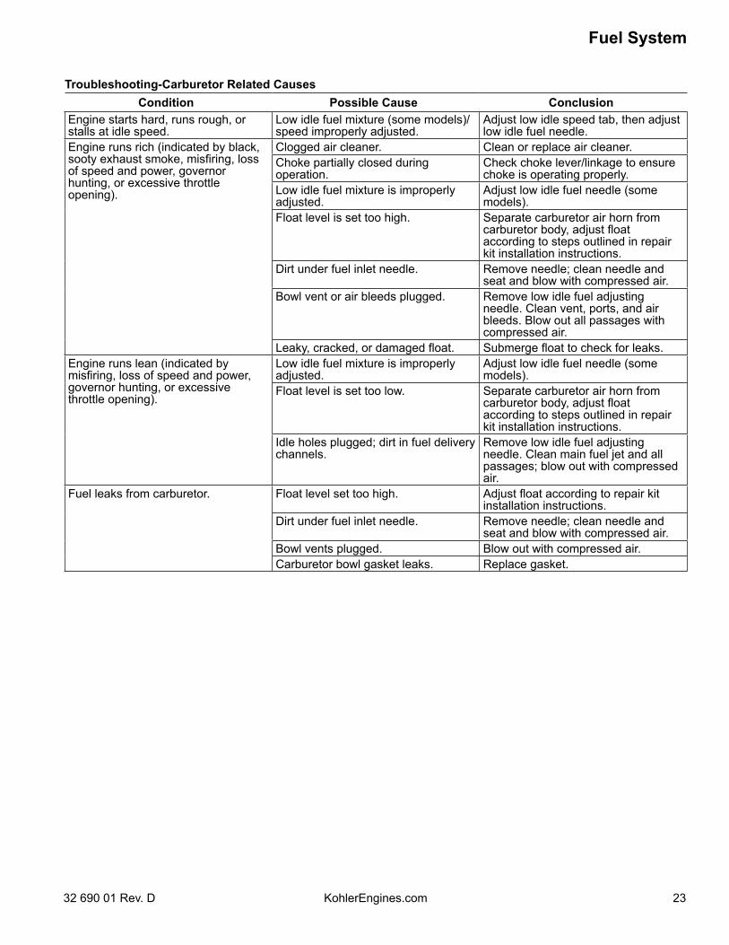
Troubleshooting-Carburetor Related CausesCondition Possible Cause Conclusion
Engine starts hard, runs rough, or stalls at idle speed.
Low idle fuel mixture (some models)/speed improperly adjusted.
Adjust low idle speed tab, then adjust low idle fuel needle.
Engine runs rich (indicated by black, sooty exhaust smoke, misfiring, loss of speed and power, governor hunting, or excessive throttle opening).
Clogged air cleaner. Clean or replace air cleaner.Choke partially closed during operation.
Check choke lever/linkage to ensure choke is operating properly.
Low idle fuel mixture is improperly adjusted.
Adjust low idle fuel needle (some models).
Float level is set too high. Separate carburetor air horn from carburetor body, adjust float according to steps outlined in repair kit installation instructions.
Dirt under fuel inlet needle. Remove needle; clean needle and seat and blow with compressed air.
Bowl vent or air bleeds plugged. Remove low idle fuel adjusting needle. Clean vent, ports, and air bleeds. Blow out all passages with compressed air.
Leaky, cracked, or damaged float. Submerge float to check for leaks.Engine runs lean (indicated by misfiring, loss of speed and power, governor hunting, or excessive throttle opening).
Low idle fuel mixture is improperly adjusted.
Adjust low idle fuel needle (some models).
Float level is set too low. Separate carburetor air horn from carburetor body, adjust float according to steps outlined in repair kit installation instructions.
Idle holes plugged; dirt in fuel delivery channels.
Remove low idle fuel adjusting needle. Clean main fuel jet and all passages; blow out with compressed air.
Fuel leaks from carburetor. Float level set too high. Adjust float according to repair kit installation instructions.
Dirt under fuel inlet needle. Remove needle; clean needle and seat and blow with compressed air.
Bowl vents plugged. Blow out with compressed air.Carburetor bowl gasket leaks. Replace gasket.
Fuel System
24 32 690 01 Rev. DKohlerEngines.com
FUEL SYSTEM
Fuel Shut-off SolenoidMost carburetors are equipped with a fuel shut-off solenoid. Solenoid is attached to fuel bowl. Solenoid has a spring-loaded pin that retracts when 12 volts is applied to lead, allowing fuel flow to main jet. When current is removed, pin extends blocking fuel flow. Below is a simple test, performed with engine off, that can determine if solenoid is functioning properly: 1. Shut off fuel and remove solenoid from carburetor.
When solenoid is loosened and removed, gas will leak out of carburetor. Have a container ready to catch fuel.
2. Wipe tip of solenoid with a shop towel or blow with compressed air to remove any remaining fuel. Take solenoid to a location with good ventilation and no fuel vapors present. You will also need a 12 volt power source that can be switched on and off.
3. Be sure power source is switched OFF. Connect positive power source lead to red lead of solenoid. Connect negative power source lead to solenoid body.
4. Turn power source ON and observe pin in center of solenoid. Pin should retract with power ON and return to its original position with power OFF. Test several times to verify operation.
Carburetor CircuitsFloat Fuel level in bowl is maintained by float and fuel inlet needle. Buoyant force of float stops fuel flow when engine is at rest. When fuel is being consumed, float will drop and fuel pressure will push inlet needle away from seat, allowing more fuel to enter bowl. When demand ceases, buoyant force of float will again overcome fuel pressure, rising to predetermined setting and stop flow. Slow and Mid-RangeAt low speeds engine operates only on slow circuit. As a metered amount of air is drawn through slow air bleed jets, fuel is drawn through main jet and further metered through slow jet. Air and fuel are mixed in body of slow jet and exit to idle progression (transfer port) chamber. From idle progression chamber, air fuel mixture is metered through idle port passage. At low idle air/fuel mixture is controlled by setting of idle fuel adjusting screws. This mixture is then mixed with main body of air and delivered to engine. As throttle plate opening increases, greater amounts of air/fuel mixture are drawn in through fixed and metered idle progression holes. As throttle plate opens further, vacuum signal becomes great enough at venturi so main circuit begins to work. Main (high-speed)At high speeds/loads engine operates on main circuit. As a metered amount of air is drawn through air jet, fuel is drawn through main jet. Air and fuel are mixed in main nozzles then enters main body of airflow where further mixing of fuel and air occurs. This mixture is then delivered to combustion chamber. Carburetor has a fixed main circuit; no adjustment is possible.
Carburetor AdjustmentsNOTE: Carburetor adjustments should be made only
after engine has warmed up. Carburetor is designed to deliver correct fuel-to-air mixture to engine under all operating conditions. Main fuel jet is calibrated at factory and is not adjustable. Idle fuel adjusting needles are also set at factory and normally do not need adjustment. Low Idle Speed (RPM) AdjustmentNOTE: Actual low idle speed depends on application.
Refer to equipment manufacturer’s recommendations. Low idle speed for basic engines is 1200 RPM.
Place throttle control into idle or slow position. Turn low idle speed adjusting screw in or out to obtain allow idle speed of 1200 RPM (± 75 RPM). Governed Idle Speed Adjustment (if equipped)1. Hold governor lever away from carburetor so throttle
lever is against idle speed (RPM) adjustment screw of carburetor. Start engine and allow to warm up, then adjust screw to set approximately 1200 RPM. Check speed using a tachometer. Turn adjustment screw (inner) clockwise (in) to increase or counterclockwise (out) to decrease speed.
2. Release governor lever and check that throttle lever is in idle position. Turn governed idle adjustment screw to obtain equipment manufacturer’s recommended idle speed (1500-1800 RPM). Some engines have a bendable tab that is used to set this speed. A pliers should be used to bend this tab to achieve recommended speed. Governed idle speed (RPM) is typically 300 RPM (approximate) higher than low idle speed.
3. Move throttle lever to wide-open/full throttle position and hold in this position. Turn high speed screw to obtain intended high speed no-load RPM. Governed idle speed must be set before making this adjustment.
Low Idle Fuel AdjustmentOptimum Low Idle Fuel Setting
BBCC
ED
AA
A Rich B LeanC Midpoint D Left SideE Right Side
NOTE: Engines will have fixed low idle or limiter caps on idle fuel adjusting needles. Step 2 can only be performed within limits allowed by cap. Do not attempt to remove limiter caps.

Fuel System
2532 690 01 Rev. D KohlerEngines.com
1. Place throttle control into idle or slow position. Adjust low idle speed to 1200 RPM. Follow Low Idle Speed (RPM) Adjustment.
2. Low idle fuel needle(s) setting: place throttle into idle or slow position.
a. Turn 1 low idle fuel adjusting needle out (counterclockwise) from preliminary setting until engine speed decreases (rich). Note position of needle. Now turn adjusting needle in (clockwise).Engine speed may increase, then it will decrease as needle is turned in (lean). Note position of needle. Set adjusting needle midway between rich and lean settings.
b. Repeat procedure on other low idle adjustment needle (two-barrel carburetor only).
3. Recheck/adjust Low Idle Speed (RPM) to specified setting.
High Speed (RPM) Adjustment1. With engine running, move throttle control to fast.2. Turn inner adjustment screw outward to decrease, or
inward to increase RPM speed. Courage singles require loosening screws on speed control bracket and sliding towards carburetor to lower and away from carburetor to increase speed.
Carburetor Servicing
WARNING
Accidental Starts can cause severe injury or death.Disconnect and ground spark plug lead(s) before servicing.
Before working on engine or equipment, disable engine as follows: 1) Disconnect spark plug lead(s). 2) Disconnect negative (–) battery cable from battery.
NOTE: Main and slow jets are fixed and size specific and can be removed if required. Fixed jets for high altitudes are available.
● Inspect carburetor body for cracks, holes, and other wear or damage.
● Inspect float for cracks, holes, and missing or damaged float tabs. Check float hinge and shaft for wear or damage.
● Inspect fuel inlet needle and seat for wear or damage.● Inspect spring loaded choke plate to make sure it
moves freely on shaft. 1. Perform removal procedures for appropriate air
cleaner and carburetor outlined in Disassembly.
2. Clean exterior surfaces of dirt or foreign material before disassembling carburetor. Remove bowl retaining screws, or solenoid assembly on most single cylinder engines, and carefully separate fuel bowl from carburetor. Do not damage fuel bowl O-rings. Transfer any remaining fuel into an approved container. Save all parts. Fuel can also be drained prior to bowl removal by loosening/removing bowl drain screw.
3. Remove float pin (some carburetors may have a screw which requires removal), and inlet needle. Seat for inlet needle is not serviceable and should not be removed.
4. Clean carburetor bowl and inlet seat areas as required.
5. Carefully remove main jets from carburetor. For two-barrel carburetors, note and mark jets by location for proper reassembly. Main jets may be size/side specific. After main jets are removed, on some carburetors, main nozzles can be removed through bottom of main towers. Note orientation/direction of nozzles. End with 2 raised shoulders should be out/down adjacent to main jets. Save parts for cleaning and reuse.
6. Position of slow jet varies and is removable only on some styles of carburetors. See correct illustration for corresponding style of carburetor showing location. (On two-barrel carburetors, slow jets may be sized to specific side. Mark or tag jets for proper reassembly. Note small O-ring on bottom of each jet.) Save parts for cleaning and reuse unless a jet kit is also being installed. Clean slow jets using compressed air. Do not use wire or carburetor cleaner.
Carburetor is now disassembled for appropriate cleaning and installation of parts in overhaul kit. See instructions provided with repair kits for more detailed information.
High Altitude OperationEngines may require a high altitude carburetor kit to ensure correct engine operation at altitudes above 1219 meters (4000 ft.). To obtain high altitude kit information or to find a Kohler authorized dealer visit KohlerEngines.com or call1-800-544-2444 (U.S. and Canada). This engine should be operated in its original configuration below 1219 meters (4000 ft.) as damage may occur if high altitude carburetor kit is installed and operated below 1219 meters (4000 ft.).
Fuel System
26 32 690 01 Rev. DKohlerEngines.com
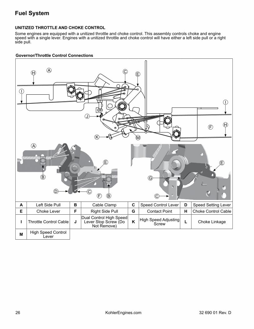
UNITIZED THROTTLE AND CHOKE CONTROLSome engines are equipped with a unitized throttle and choke control. This assembly controls choke and engine speed with a single lever. Engines with a unitized throttle and choke control will have either a left side pull or a right side pull.
Governor/Throttle Control Connections
M
C E
I
H
I
H
A
F
J
K
B
B
E
D CF
A
E
G
C
A Left Side Pull B Cable Clamp C Speed Control Lever D Speed Setting LeverE Choke Lever F Right Side Pull G Contact Point H Choke Control Cable
I Throttle Control Cable JDual Control High Speed
Lever Stop Screw (Do Not Remove)
K High Speed Adjusting Screw L Choke Linkage
M High Speed Control Lever
Fuel System
2732 690 01 Rev. D KohlerEngines.com
Throttle Cable AdjustmentNOTE: Choke is placed ON by moving throttle control
slightly past fast position. If throttle control does not have a designated choke ON position, be sure to leave sufficient throttle control travel past fast position. This will enable choke to be placed ON.
1. Loosen control cable clamp.2. Place throttle control lever of equipment into fast or
high speed position.3. Pull on outer shield of throttle control cable until
speed control lever rotates and makes contact with choke lever. Tighten cable clamp securely.
Starting an Engine Equipped with Unitized Throttle and Choke ControlNOTE: Do not crank engine continuously for more than
10 seconds at a time. If engine does not start, allow a 60 second cool down period between starting attempts. Failure to follow these guidelines can burn out starter motor.
NOTE: If engine develops sufficient speed to disengage starter but does not keep running (a false start), engine rotation must be allowed to come to a complete stop before attempting to restart engine. If starter is engaged while flywheel is rotating, starter pinion and flywheel ring gear may clash, resulting in damage to starter.
1. For a Cold or Warm Engine – Place throttle/choke control into fast/choke ON position. This will also place choke into ON position.
2. Make sure equipment is in neutral.3. Activate starter switch. Release switch as soon as
engine starts.If starter does not turn engine over, shut starter off immediately. Do not make further attempts to start engine until condition is corrected. Do not jump start using another battery. See your Kohler authorized dealer for trouble analysis.4. For Operation – After engine starts, move throttle/
choke control from fast/choke ON position and set desired engine operating speed (between slow and fast position).
Governor System
28 32 690 01 Rev. DKohlerEngines.com
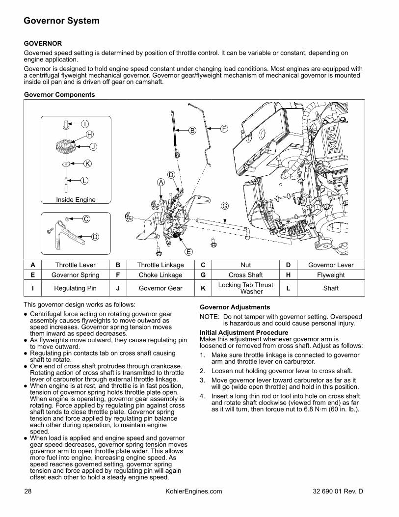
GOVERNORGoverned speed setting is determined by position of throttle control. It can be variable or constant, depending on engine application.Governor is designed to hold engine speed constant under changing load conditions. Most engines are equipped with a centrifugal flyweight mechanical governor. Governor gear/flyweight mechanism of mechanical governor is mounted inside oil pan and is driven off gear on camshaft.
Governor Components
F
E
B
AD
I
K
J
H
L
Inside Engine
C
D
G
A Throttle Lever B Throttle Linkage C Nut D Governor LeverE Governor Spring F Choke Linkage G Cross Shaft H Flyweight
I Regulating Pin J Governor Gear K Locking Tab Thrust Washer L Shaft
This governor design works as follows:● Centrifugal force acting on rotating governor gear
assembly causes flyweights to move outward as speed increases. Governor spring tension moves them inward as speed decreases.
● As flyweights move outward, they cause regulating pin to move outward.
● Regulating pin contacts tab on cross shaft causing shaft to rotate.
● One end of cross shaft protrudes through crankcase. Rotating action of cross shaft is transmitted to throttle lever of carburetor through external throttle linkage.
● When engine is at rest, and throttle is in fast position, tension of governor spring holds throttle plate open. When engine is operating, governor gear assembly is rotating. Force applied by regulating pin against cross shaft tends to close throttle plate. Governor spring tension and force applied by regulating pin balance each other during operation, to maintain engine speed.
● When load is applied and engine speed and governor gear speed decreases, governor spring tension moves governor arm to open throttle plate wider. This allows more fuel into engine, increasing engine speed. As speed reaches governed setting, governor spring tension and force applied by regulating pin will again offset each other to hold a steady engine speed.
Governor AdjustmentsNOTE: Do not tamper with governor setting. Overspeed
is hazardous and could cause personal injury.Initial Adjustment ProcedureMake this adjustment whenever governor arm is loosened or removed from cross shaft. Adjust as follows:1. Make sure throttle linkage is connected to governor
arm and throttle lever on carburetor.2. Loosen nut holding governor lever to cross shaft.3. Move governor lever toward carburetor as far as it
will go (wide open throttle) and hold in this position.4. Insert a long thin rod or tool into hole on cross shaft
and rotate shaft clockwise (viewed from end) as far as it will turn, then torque nut to 6.8 N·m (60 in. lb.).
29
Lubrication System
32 690 01 Rev. D KohlerEngines.com
OIL RECOMMENDATIONSRefer to Maintenance.
CHECK OIL LEVELNOTE: To prevent extensive engine wear or damage,
never run engine with oil level below or above operating range indicator on dipstick.
Ensure engine is cool. Clean oil fill/dipstick areas of any debris.1. Remove dipstick; wipe oil off. a. Push-in cap: reinsert dipstick into tube; press
completely down.or
b. Threaded cap: reinsert dipstick into tube and thread on completely.
2. Remove dipstick; check oil level. Level should be at top of indicator on dipstick.
3. If oil is low on indicator, add oil up to top of indicator mark.
4. Reinstall and secure dipstick.
CHANGE OIL AND FILTERChange oil while engine is warm.1. Clean area around oil fill cap/dipstick. Remove drain
plug and oil fill cap/dipstick. Allow oil to drain completely.
2. Clean area around oil filter. Place a container under filter to catch any oil and remove filter. Wipe off mounting surface. Reinstall drain plug. Torque to 13.6 N·m (10 ft. lb.).
3. Place new filter in shallow pan with open end up. Fill with new oil until oil reaches bottom of threads. Allow 2 minutes for oil to be absorbed by filter material.
4. Apply a thin film of clean oil to rubber gasket on new filter.
5. Refer to instructions on oil filter for proper installation.
6. Fill crankcase with new oil. Level should be at top of indicator on dipstick.
7. Reinstall oil fill cap/dipstick and tighten securely.8. Start engine; check for oil leaks. Stop engine; correct
leaks. Recheck oil level.9. Dispose of used oil and filter in accordance with
local ordinances.
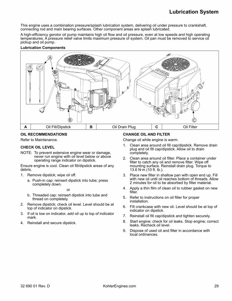
A
B C
A Oil Fill/Dipstick B Oil Drain Plug C Oil Filter
This engine uses a combination pressure/splash lubrication system, delivering oil under pressure to crankshaft, connecting rod and main bearing surfaces. Other component areas are splash lubricated.A high-efficiency gerotor oil pump maintains high oil flow and oil pressure, even at low speeds and high operating temperatures. A pressure relief valve limits maximum pressure of system. Oil pan must be removed to service oil pickup and oil pump.Lubrication Components
30
Lubrication System
KohlerEngines.com 32 690 01 Rev. D
OIL SENTRY™ (if equipped)NOTE: Make sure oil level is checked before each use,
and is maintained up to FULL or F mark on dipstick. This includes engines equipped with Oil Sentry™.
This switch is designed to prevent engine from starting in a low oil or no oil condition. Oil Sentry™ may not shut down a running engine before damage occurs. In some applications this switch may activate a warning signal. Read your equipment manuals for more information.Oil Sentry™ pressure switch is installed in oil filter adapter. Pressure switch is designed to break contact as oil pressure increases above 3-5 psi, and make contact as oil pressure decreases below 3-5 psi.On stationary or unattended applications (pumps, generators, etc.), pressure switch can be used to ground ignition module to stop engine. On vehicular applications (lawn tractors, mowers, etc.) pressure switch can only be used to activate a low oil warning light or signal.
Installation1. Apply pipe sealant with Teflon® (Loctite® PST® 592™
Thread Sealant or equivalent) to threads of switch.2. Install switch into tapped hole in oil filter adapter.3. Torque switch to 4.5 N·m (40 in. lb.).
TestingCompressed air, a pressure regulator, pressure gauge, and a continuity tester are required to test switch.1. Connect continuity tester across blade terminal and
metal case of switch. With 0 psi pressure applied to switch, tester should indicate continuity (switch closed).
2. Gradually increase pressure to switch. As pressure increases through range of 2-5 psi tester should indicate a change to no continuity (switch open). Switch should remain open as pressure is increased to 90 psi maximum.
3. Gradually decrease pressure through range of 2-5 psi. Tester should indicate a change to continuity (switch closed) down to 0 psi.
4. Replace switch if it does not operate as specified.
Electrical System
3132 690 01 Rev. D KohlerEngines.com
SPARK PLUGS
CAUTIONElectrical Shock can cause injury.Do not touch wires while engine is running.
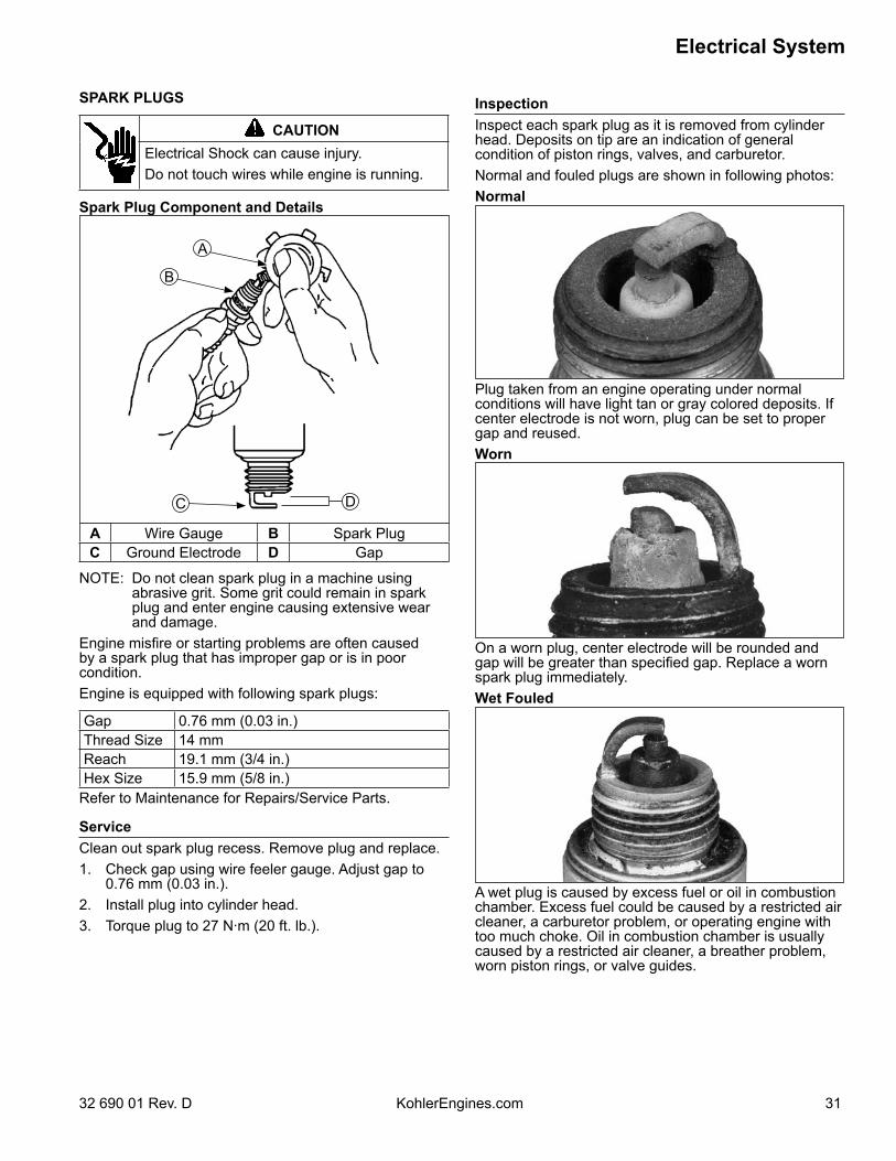
Spark Plug Component and Details
B
A
C D
A Wire Gauge B Spark PlugC Ground Electrode D Gap
NOTE: Do not clean spark plug in a machine using abrasive grit. Some grit could remain in spark plug and enter engine causing extensive wear and damage.
Engine misfire or starting problems are often caused by a spark plug that has improper gap or is in poor condition.Engine is equipped with following spark plugs:
Gap 0.76 mm (0.03 in.)Thread Size 14 mmReach 19.1 mm (3/4 in.)Hex Size 15.9 mm (5/8 in.)
Refer to Maintenance for Repairs/Service Parts.
ServiceClean out spark plug recess. Remove plug and replace.1. Check gap using wire feeler gauge. Adjust gap to
0.76 mm (0.03 in.).2. Install plug into cylinder head.3. Torque plug to 27 N·m (20 ft. lb.).
InspectionInspect each spark plug as it is removed from cylinder head. Deposits on tip are an indication of general condition of piston rings, valves, and carburetor.Normal and fouled plugs are shown in following photos:Normal
Plug taken from an engine operating under normal conditions will have light tan or gray colored deposits. If center electrode is not worn, plug can be set to proper gap and reused.Worn
On a worn plug, center electrode will be rounded and gap will be greater than specified gap. Replace a worn spark plug immediately.Wet Fouled
A wet plug is caused by excess fuel or oil in combustion chamber. Excess fuel could be caused by a restricted air cleaner, a carburetor problem, or operating engine with too much choke. Oil in combustion chamber is usually caused by a restricted air cleaner, a breather problem, worn piston rings, or valve guides.
Electrical System
32 32 690 01 Rev. DKohlerEngines.com
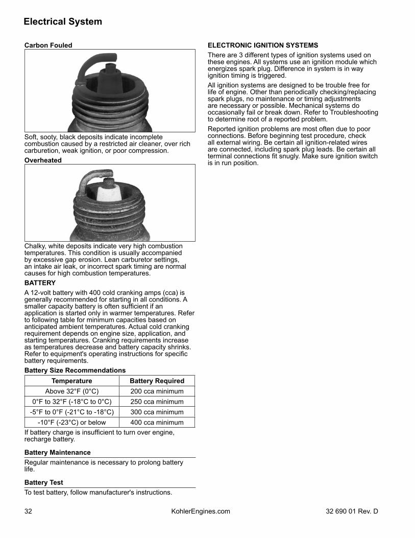
Carbon Fouled
Soft, sooty, black deposits indicate incomplete combustion caused by a restricted air cleaner, over rich carburetion, weak ignition, or poor compression.Overheated
Chalky, white deposits indicate very high combustion temperatures. This condition is usually accompanied by excessive gap erosion. Lean carburetor settings, an intake air leak, or incorrect spark timing are normal causes for high combustion temperatures.BATTERYA 12-volt battery with 400 cold cranking amps (cca) is generally recommended for starting in all conditions. A smaller capacity battery is often sufficient if an application is started only in warmer temperatures. Refer to following table for minimum capacities based on anticipated ambient temperatures. Actual cold cranking requirement depends on engine size, application, and starting temperatures. Cranking requirements increase as temperatures decrease and battery capacity shrinks. Refer to equipment's operating instructions for specific battery requirements.Battery Size Recommendations
Temperature Battery RequiredAbove 32°F (0°C) 200 cca minimum
0°F to 32°F (-18°C to 0°C) 250 cca minimum-5°F to 0°F (-21°C to -18°C) 300 cca minimum
-10°F (-23°C) or below 400 cca minimumIf battery charge is insufficient to turn over engine, recharge battery.
Battery MaintenanceRegular maintenance is necessary to prolong battery life.
Battery TestTo test battery, follow manufacturer's instructions.
ELECTRONIC IGNITION SYSTEMSThere are 3 different types of ignition systems used on these engines. All systems use an ignition module which energizes spark plug. Difference in system is in way ignition timing is triggered.All ignition systems are designed to be trouble free for life of engine. Other than periodically checking/replacing spark plugs, no maintenance or timing adjustments are necessary or possible. Mechanical systems do occasionally fail or break down. Refer to Troubleshooting to determine root of a reported problem.Reported ignition problems are most often due to poor connections. Before beginning test procedure, check all external wiring. Be certain all ignition-related wires are connected, including spark plug leads. Be certain all terminal connections fit snugly. Make sure ignition switch is in run position.
Electrical System
3332 690 01 Rev. D KohlerEngines.com
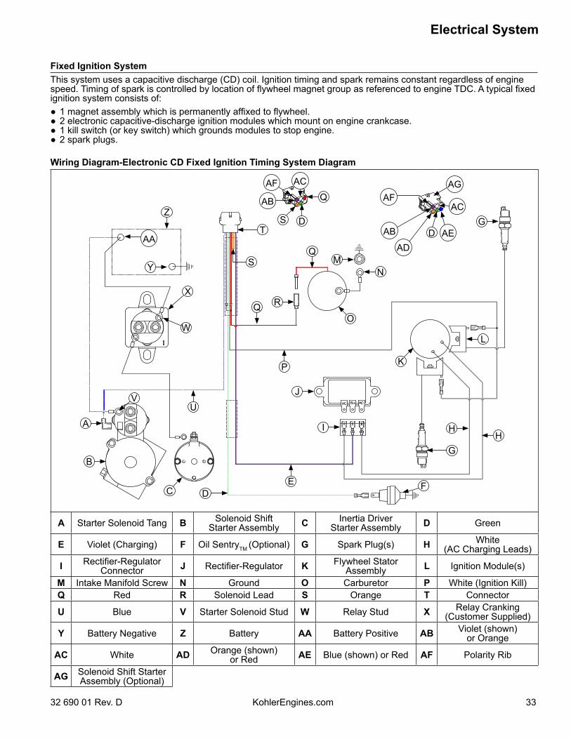
Fixed Ignition SystemThis system uses a capacitive discharge (CD) coil. Ignition timing and spark remains constant regardless of engine speed. Timing of spark is controlled by location of flywheel magnet group as referenced to engine TDC. A typical fixed ignition system consists of:● 1 magnet assembly which is permanently affixed to flywheel.● 2 electronic capacitive-discharge ignition modules which mount on engine crankcase.● 1 kill switch (or key switch) which grounds modules to stop engine.● 2 spark plugs.
Wiring Diagram-Electronic CD Fixed Ignition Timing System Diagram
H
Q
L
G
AD
DD
ST
H
M
K
FD
J
I
G
EC
B
A
UV
W
X
Y
Z
S
R
P
Q
Q
N
O
AAAB AE
AFAF
ACAB
AC AG
A Starter Solenoid Tang B Solenoid ShiftStarter Assembly C Inertia Driver
Starter Assembly D Green
E Violet (Charging) F Oil SentryTM (Optional) G Spark Plug(s) H White(AC Charging Leads)
I Rectifier-RegulatorConnector J Rectifier-Regulator K Flywheel Stator
Assembly L Ignition Module(s)
M Intake Manifold Screw N Ground O Carburetor P White (Ignition Kill)Q Red R Solenoid Lead S Orange T Connector
U Blue V Starter Solenoid Stud W Relay Stud X Relay Cranking(Customer Supplied)
Y Battery Negative Z Battery AA Battery Positive AB Violet (shown)or Orange
AC White AD Orange (shown)or Red AE Blue (shown) or Red AF Polarity Rib
AG Solenoid Shift StarterAssembly (Optional)
Electrical System
34 32 690 01 Rev. DKohlerEngines.com
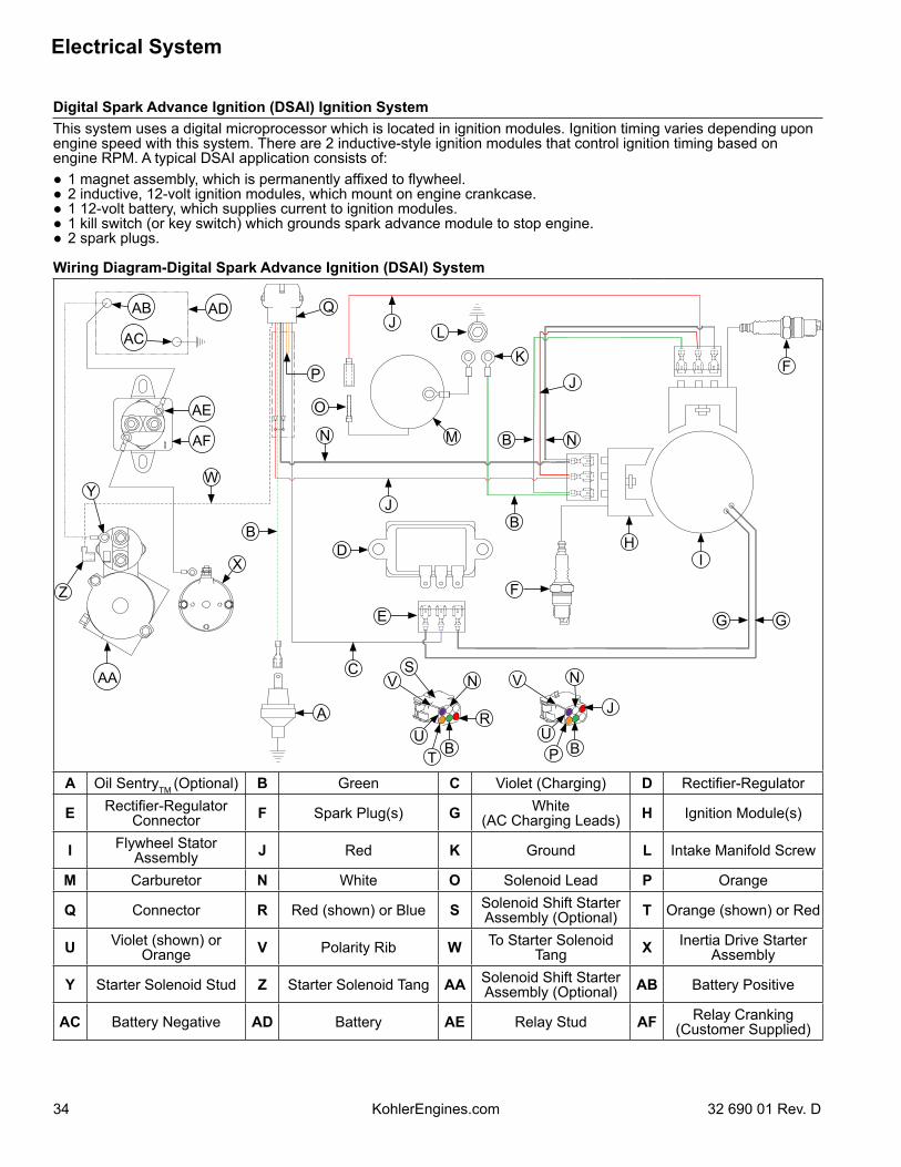
Digital Spark Advance Ignition (DSAI) Ignition SystemThis system uses a digital microprocessor which is located in ignition modules. Ignition timing varies depending upon engine speed with this system. There are 2 inductive-style ignition modules that control ignition timing based on engine RPM. A typical DSAI application consists of:● 1 magnet assembly, which is permanently affixed to flywheel.● 2 inductive, 12-volt ignition modules, which mount on engine crankcase.● 1 12-volt battery, which supplies current to ignition modules.● 1 kill switch (or key switch) which grounds spark advance module to stop engine.● 2 spark plugs.
Wiring Diagram-Digital Spark Advance Ignition (DSAI) System
R
N
O
UA
B
C
E
D
F
F
IH
G G
B
B
J
JL
K
MN
J
W
X
Y
Z
Q
P
BT
V V
UP B
J
N NS
AB AD
AF
AE
AC
AA
A Oil SentryTM (Optional) B Green C Violet (Charging) D Rectifier-Regulator
E Rectifier-RegulatorConnector F Spark Plug(s) G White
(AC Charging Leads) H Ignition Module(s)
I Flywheel Stator Assembly J Red K Ground L Intake Manifold Screw
M Carburetor N White O Solenoid Lead P Orange
Q Connector R Red (shown) or Blue S Solenoid Shift Starter Assembly (Optional) T Orange (shown) or Red
U Violet (shown) or Orange V Polarity Rib W To Starter Solenoid
Tang X Inertia Drive Starter Assembly
Y Starter Solenoid Stud Z Starter Solenoid Tang AA Solenoid Shift Starter Assembly (Optional) AB Battery Positive
AC Battery Negative AD Battery AE Relay Stud AF Relay Cranking (Customer Supplied)
Electrical System
3532 690 01 Rev. D KohlerEngines.com
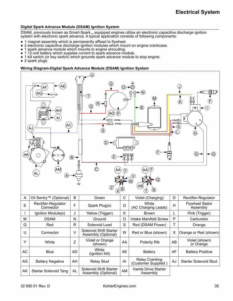
Digital Spark Advance Module (DSAM) Ignition SystemDSAM, previously known as Smart-Spark™, equipped engines utilize an electronic capacitive discharge ignition system with electronic spark advance. A typical application consists of following components:● 1 magnet assembly which is permanently affixed to flywheel.● 2 electronic capacitive discharge ignition modules which mount on engine crankcase.● 1 spark advance module which mounts to engine shrouding.● 1 12-volt battery which supplies current to spark advance module.● 1 kill switch (or key switch) which grounds spark advance module to stop engine.● 2 spark plugs.
Wiring Diagram-Digital Spark Advance Module (DSAM) Ignition System
W
BR
Z
A
B
C
E
D
F
F
H
K
G G
JQ
ON
P
Q
S
U
T
BX T B
Q
Y Y
KL
M
I
V
AI
AH
AFAG
AE
AMAL
AK
AAAA
AB
AJAC
AD
A Oil Sentry™ (Optional) B Green C Violet (Charging) D Rectifier-Regulator
E Rectifier-RegulatorConnector F Spark Plug(s) G White
(AC Charging Leads) H Flywheel Stator Assembly
I Ignition Module(s) J Yellow (Trigger) K Brown L Pink (Trigger)M DSAM N Ground O Intake Manifold Screw P CarburetorQ Red R Solenoid Lead S Red (DSAM Power) T Orange
U Connector V Solenoid Shift Starter Assembly (Optional) W Red or Blue (shown) X Orange or Red (shown)
Y White Z Violet or Orange (shown) AA Polarity Rib AB Violet (shown)
or Orange
AC Blue AD White(Ignition Kill) AE Battery AF Battery Positive
AG Battery Negative AH Relay Stud AI Relay Cranking (Customer Supplied ) AJ Starter Solenoid Stud
AK Starter Solenoid Tang AL Solenoid Shift Starter Assembly (Optional) AM Inertia Drive Starter
Assembly
Electrical System
36 32 690 01 Rev. DKohlerEngines.com
Electronic Ignition Systems TestsNOTE: Ignition tester must be used to test ignition on these engines. Use of any other tester can result in inaccurate
findings. Battery on unit must be fully charged and properly connected before performing tests (a battery that is hooked up or charged backward will crank engine but it won’t have spark). Be certain drive is in neutral and all external loads are disconnected.
Test Ignition SystemsNOTE: If engine starts or runs during testing, you may need to ground kill lead to shut it down. Because you have
interrupted kill circuit, it may not stop using switch.Isolate and verify trouble is within engine.1. Locate connectors where wiring harnesses from engine and equipment are joined. Separate connectors and
remove white kill lead from engine connector. Rejoin connectors and position or insulate kill lead terminal so it cannot touch ground. Try to start engine to verify whether reported problem is still present.
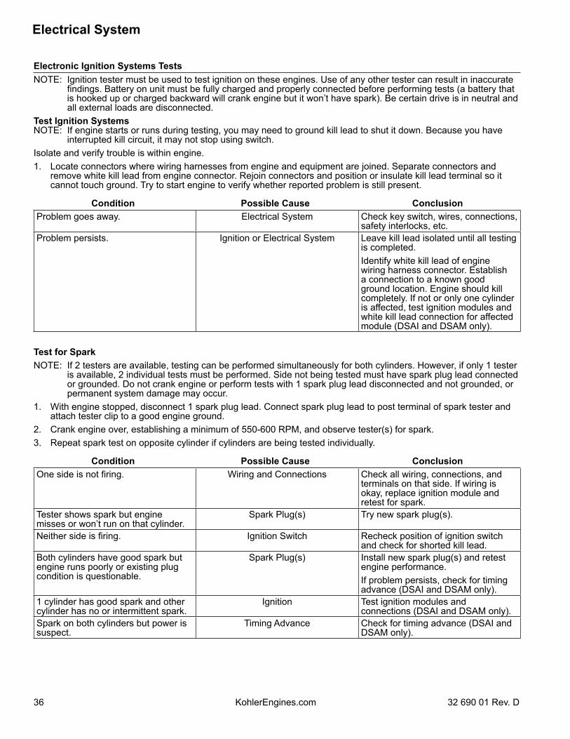
Condition Possible Cause ConclusionProblem goes away. Electrical System Check key switch, wires, connections,
safety interlocks, etc.Problem persists. Ignition or Electrical System Leave kill lead isolated until all testing
is completed.Identify white kill lead of engine wiring harness connector. Establish a connection to a known good ground location. Engine should kill completely. If not or only one cylinder is affected, test ignition modules and white kill lead connection for affected module (DSAI and DSAM only).
Test for SparkNOTE: If 2 testers are available, testing can be performed simultaneously for both cylinders. However, if only 1 tester
is available, 2 individual tests must be performed. Side not being tested must have spark plug lead connected or grounded. Do not crank engine or perform tests with 1 spark plug lead disconnected and not grounded, or permanent system damage may occur.
1. With engine stopped, disconnect 1 spark plug lead. Connect spark plug lead to post terminal of spark tester and attach tester clip to a good engine ground.
2. Crank engine over, establishing a minimum of 550-600 RPM, and observe tester(s) for spark.3. Repeat spark test on opposite cylinder if cylinders are being tested individually.
Condition Possible Cause ConclusionOne side is not firing. Wiring and Connections Check all wiring, connections, and
terminals on that side. If wiring is okay, replace ignition module and retest for spark.
Tester shows spark but engine misses or won’t run on that cylinder.
Spark Plug(s) Try new spark plug(s).
Neither side is firing. Ignition Switch Recheck position of ignition switch and check for shorted kill lead.
Both cylinders have good spark but engine runs poorly or existing plug condition is questionable.
Spark Plug(s) Install new spark plug(s) and retest engine performance.If problem persists, check for timing advance (DSAI and DSAM only).
1 cylinder has good spark and other cylinder has no or intermittent spark.
Ignition Test ignition modules and connections (DSAI and DSAM only).
Spark on both cylinders but power is suspect.
Timing Advance Check for timing advance (DSAI and DSAM only).
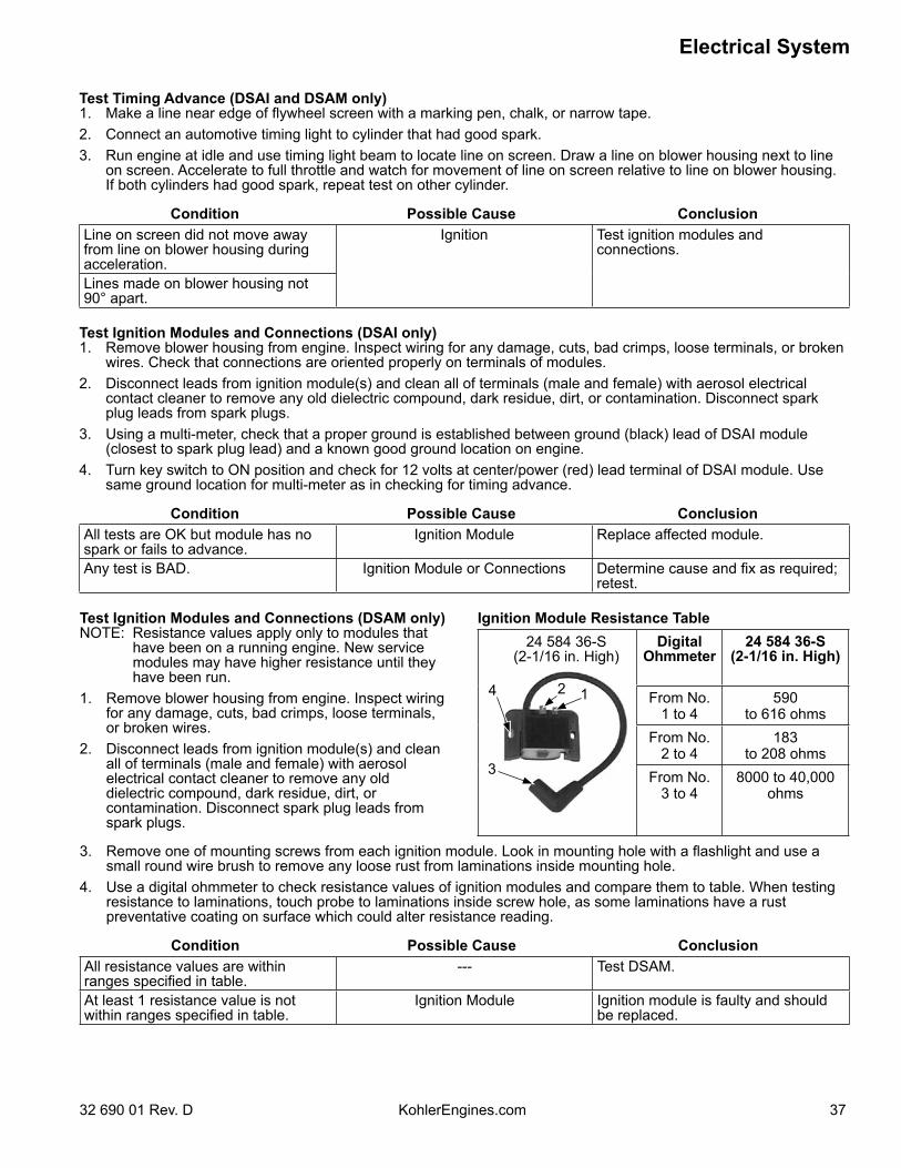
Electrical System
3732 690 01 Rev. D KohlerEngines.com
Test Timing Advance (DSAI and DSAM only)1. Make a line near edge of flywheel screen with a marking pen, chalk, or narrow tape.2. Connect an automotive timing light to cylinder that had good spark.3. Run engine at idle and use timing light beam to locate line on screen. Draw a line on blower housing next to line
on screen. Accelerate to full throttle and watch for movement of line on screen relative to line on blower housing. If both cylinders had good spark, repeat test on other cylinder.
Condition Possible Cause ConclusionLine on screen did not move away from line on blower housing during acceleration.
Ignition Test ignition modules and connections.
Lines made on blower housing not 90° apart.
Test Ignition Modules and Connections (DSAI only)1. Remove blower housing from engine. Inspect wiring for any damage, cuts, bad crimps, loose terminals, or broken
wires. Check that connections are oriented properly on terminals of modules.2. Disconnect leads from ignition module(s) and clean all of terminals (male and female) with aerosol electrical
contact cleaner to remove any old dielectric compound, dark residue, dirt, or contamination. Disconnect spark plug leads from spark plugs.
3. Using a multi-meter, check that a proper ground is established between ground (black) lead of DSAI module (closest to spark plug lead) and a known good ground location on engine.
4. Turn key switch to ON position and check for 12 volts at center/power (red) lead terminal of DSAI module. Use same ground location for multi-meter as in checking for timing advance.
Condition Possible Cause ConclusionAll tests are OK but module has no spark or fails to advance.
Ignition Module Replace affected module.
Any test is BAD. Ignition Module or Connections Determine cause and fix as required; retest.
Test Ignition Modules and Connections (DSAM only)NOTE: Resistance values apply only to modules that
have been on a running engine. New service modules may have higher resistance until they have been run.
1. Remove blower housing from engine. Inspect wiring for any damage, cuts, bad crimps, loose terminals, or broken wires.
2. Disconnect leads from ignition module(s) and clean all of terminals (male and female) with aerosol electrical contact cleaner to remove any old dielectric compound, dark residue, dirt, or contamination. Disconnect spark plug leads from spark plugs.
Ignition Module Resistance Table
4 2 1
3
24 584 36-S(2-1/16 in. High)
DigitalOhmmeter
24 584 36-S(2-1/16 in. High)
From No.1 to 4
590to 616 ohms
From No.2 to 4
183to 208 ohms
From No.3 to 4
8000 to 40,000 ohms
3. Remove one of mounting screws from each ignition module. Look in mounting hole with a flashlight and use a small round wire brush to remove any loose rust from laminations inside mounting hole.
4. Use a digital ohmmeter to check resistance values of ignition modules and compare them to table. When testing resistance to laminations, touch probe to laminations inside screw hole, as some laminations have a rust preventative coating on surface which could alter resistance reading.
Condition Possible Cause ConclusionAll resistance values are within ranges specified in table.
--- Test DSAM.
At least 1 resistance value is not within ranges specified in table.
Ignition Module Ignition module is faulty and should be replaced.
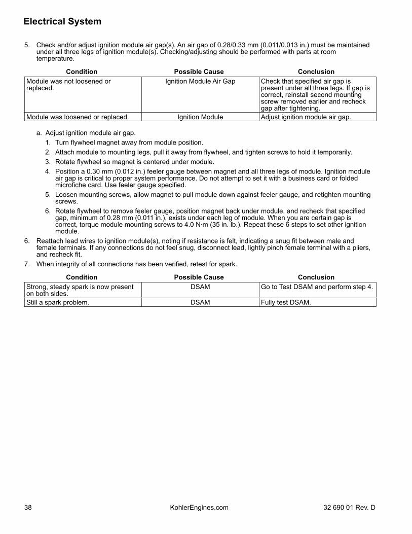
Electrical System
38 32 690 01 Rev. DKohlerEngines.com
5. Check and/or adjust ignition module air gap(s). An air gap of 0.28/0.33 mm (0.011/0.013 in.) must be maintained under all three legs of ignition module(s). Checking/adjusting should be performed with parts at room temperature.
Condition Possible Cause ConclusionModule was not loosened or replaced.
Ignition Module Air Gap Check that specified air gap is present under all three legs. If gap is correct, reinstall second mounting screw removed earlier and recheck gap after tightening.
Module was loosened or replaced. Ignition Module Adjust ignition module air gap.
a. Adjust ignition module air gap. 1. Turn flywheel magnet away from module position. 2. Attach module to mounting legs, pull it away from flywheel, and tighten screws to hold it temporarily. 3. Rotate flywheel so magnet is centered under module. 4. Position a 0.30 mm (0.012 in.) feeler gauge between magnet and all three legs of module. Ignition module
air gap is critical to proper system performance. Do not attempt to set it with a business card or folded microfiche card. Use feeler gauge specified.
5. Loosen mounting screws, allow magnet to pull module down against feeler gauge, and retighten mounting screws.
6. Rotate flywheel to remove feeler gauge, position magnet back under module, and recheck that specified gap, minimum of 0.28 mm (0.011 in.), exists under each leg of module. When you are certain gap is correct, torque module mounting screws to 4.0 N·m (35 in. lb.). Repeat these 6 steps to set other ignition module.
6. Reattach lead wires to ignition module(s), noting if resistance is felt, indicating a snug fit between male and female terminals. If any connections do not feel snug, disconnect lead, lightly pinch female terminal with a pliers, and recheck fit.
7. When integrity of all connections has been verified, retest for spark.
Condition Possible Cause ConclusionStrong, steady spark is now present on both sides.
DSAM Go to Test DSAM and perform step 4.
Still a spark problem. DSAM Fully test DSAM.
Electrical System
3932 690 01 Rev. D KohlerEngines.com
Test DSAM1. Trace red power source lead from DSAM to harness connection. Separate connector and connect red lead of a
DC voltmeter to harness terminal. Trace ground lead (green) from SAM to grounding screw. Connect black voltmeter lead to eyelet terminal of ground lead or ground screw/bolt. Check voltage with key switch in both START and RUN positions. A minimum of 7.25 volts must be present.
a. If correct voltage is not measured, connect black voltmeter lead directly to negative (-) post of battery and test voltage again in both key positions. If correct voltage is now indicated, check ground circuit connections. If ground screw/bolt or any other fasteners in ground circuit are black (oxide-coated), replace them with zinc plated (silver colored) fasteners.
b. If correct voltage is still not indicated, check harness connector terminal for a good connection and crimp to lead. Then trace power source circuit back through harness, key switch, etc., looking for any poor connections, or faulty circuits.
Condition Possible Cause ConclusionIncorrect voltage is measured. Voltage Connect black voltmeter lead directly
to negative (-) post of battery and test voltage again in both key positions.If correct voltage is still not indicated, check harness connector terminal for a good connection and crimp to lead. Then trace power source circuit back through harness, key switch, etc., looking for any poor connections, or faulty circuits.
Correct voltage is measured. Voltage Check ground circuit connections. If ground screw/bolt or any other fasteners in ground circuit are black (oxide-coated), replace them with zinc plated (silver colored) fasteners.
2. Disconnect all of DSAM leads, isolating it from engine. Test DSAM with tester 25 761 40-S, using instructions following, or use TT-5152 provided with tester. If DSAM tests bad, replace it.
3. Reattach DSAM leads, verifying a snug fit at ignition module terminals. If any connections do not feel snug, disconnect lead, lightly pinch female terminal with a pliers, and recheck fit.
4. Seal base of ignition module connections with GE/Novaguard G661 or Fel-Pro Lubri-Sel dielectric compound. Beads should overlap between two connections to form a solid bridge of compound. Do not put any compound inside connectors.
5. Test for spark to be sure system is working, before you reinstall blower housing. If there is still a spark problem on one side, replace that ignition module and recheck spark.
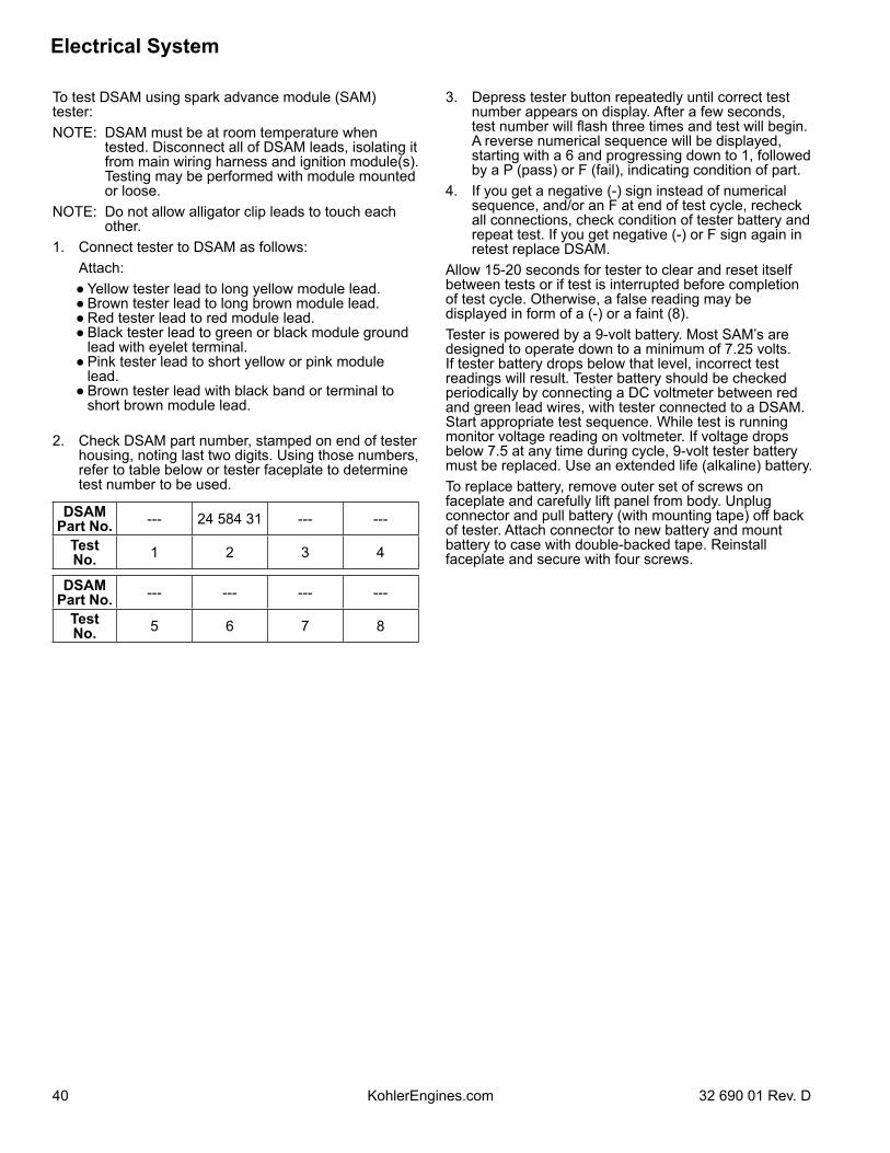
Electrical System
40 32 690 01 Rev. DKohlerEngines.com
To test DSAM using spark advance module (SAM) tester:NOTE: DSAM must be at room temperature when
tested. Disconnect all of DSAM leads, isolating it from main wiring harness and ignition module(s). Testing may be performed with module mounted or loose.
NOTE: Do not allow alligator clip leads to touch each other.
1. Connect tester to DSAM as follows: Attach: ● Yellow tester lead to long yellow module lead. ● Brown tester lead to long brown module lead. ● Red tester lead to red module lead. ● Black tester lead to green or black module ground
lead with eyelet terminal. ● Pink tester lead to short yellow or pink module
lead. ● Brown tester lead with black band or terminal to
short brown module lead.
2. Check DSAM part number, stamped on end of tester housing, noting last two digits. Using those numbers, refer to table below or tester faceplate to determine test number to be used.
DSAMPart No. --- 24 584 31 --- ---
Test No. 1 2 3 4
DSAMPart No. --- --- --- ---
Test No. 5 6 7 8
3. Depress tester button repeatedly until correct test number appears on display. After a few seconds, test number will flash three times and test will begin. A reverse numerical sequence will be displayed, starting with a 6 and progressing down to 1, followed by a P (pass) or F (fail), indicating condition of part.
4. If you get a negative (-) sign instead of numerical sequence, and/or an F at end of test cycle, recheck all connections, check condition of tester battery and repeat test. If you get negative (-) or F sign again in retest replace DSAM.
Allow 15-20 seconds for tester to clear and reset itself between tests or if test is interrupted before completion of test cycle. Otherwise, a false reading may be displayed in form of a (-) or a faint (8).Tester is powered by a 9-volt battery. Most SAM’s are designed to operate down to a minimum of 7.25 volts. If tester battery drops below that level, incorrect test readings will result. Tester battery should be checked periodically by connecting a DC voltmeter between red and green lead wires, with tester connected to a DSAM. Start appropriate test sequence. While test is running monitor voltage reading on voltmeter. If voltage drops below 7.5 at any time during cycle, 9-volt tester battery must be replaced. Use an extended life (alkaline) battery.To replace battery, remove outer set of screws on faceplate and carefully lift panel from body. Unplug connector and pull battery (with mounting tape) off back of tester. Attach connector to new battery and mount battery to case with double-backed tape. Reinstall faceplate and secure with four screws.
Electrical System
4132 690 01 Rev. D KohlerEngines.com
BATTERY CHARGING SYSTEM NOTE: Observe following guidelines to avoid damage to electrical system and components:● Make sure battery polarity is correct. A negative (-) ground system is used.● Disconnect rectifier-regulator plug and/or wiring harness plug before doing any electric welding on equipment
powered by engine. Disconnect all other electrical accessories in common ground with engine.● Prevent stator (AC) leads from touching or shorting while engine is running. This could damage stator.
Most engines are equipped with a 15 amp regulated charging system. Some have a 25 amp regulated charging system.15/25 Amp Regulated Charging SystemStatorStator is mounted on crankcase behind flywheel. Follow procedures in Disassembly and Reassembly if stator replacement is necessary.Rectifier-RegulatorNOTE: When installing rectifier-regulator, take note of terminal positions and install plug correctly.NOTE: Disconnect all electrical connections attached to rectifier-regulator. Testing may be performed with rectifier-
regulator mounted or loose. Repeat applicable test procedure 2 or 3 times to determine condition of part.Rectifier-regulator is mounted on backing shroud assembly. To replace it, disconnect plug, remove mounting screws, and ground lead.Testing rectifier-regulator may be performed as follows, using appropriate rectifier-regulator tester.
To test 25 amp rectifier-regulators:1. Connect single lead adapter in between B+ (center)
terminal of rectifier-regulator being tested and squared single end of tandem adapter lead.
2. Connect tester ground lead (with spring clamp) to body of rectifier-regulator.
3. Connect red lead and 1 black lead to terminals on open end of tandem adapter lead (connections are not location specific).
4. Connect remaining black lead from tester to 1 outer AC terminal on rectifier-regulator.
5. Plug tester into proper AC outlet/power for tester being used. Turn on power switch. POWER light should be illuminated and 1 of 4 status lights may be on as well. This does not represent condition of part.
6. Press TEST button until a click is heard and then release. Momentarily 1 of 4 lights will illuminate indicating partial condition of part.
To test 15 amp rectifier-regulators:1. Connect tester ground lead (with spring clamp) to
body of rectifier-regulator being tested.2. Connect tester red lead to B+ terminal of rectifier-
regulator and 2 black tester leads to 2 AC terminals.3. Plug tester into proper AC outlet/power for tester
being used. Turn on power switch. POWER light should be illuminated and 1 of 4 status lights may be on as well. This does not represent condition of part.
4. Press TEST button until a click is heard and then release. Momentarily 1 of 4 status lights will illuminate indicating condition of part.
Condition Conclusion25 amp 15 amp
OK (green) light comes on and stays steady. Disconnect tester black lead attached to 1 AC terminal and reconnect it to other AC terminal. Repeat test. If OK (green) light comes on again, part is good and may be used.
Part is good and may be used.
NOTE: A flashing LOW light can also occur as a result of an inadequate ground lead connection. Make certain connection location is clean and clamp is secure.
Other lights come on.
Rectifier-regulator is faulty and should not be used.
Electrical System
42 32 690 01 Rev. DKohlerEngines.com
15/25 Amp Battery Charging SystemsNOTE: Always zero ohmmeter on each scale before testing to ensure accurate readings. Voltage tests should be
made with engine running at 3600 RPM with no load. Battery must be good and fully charged.When problems occur in keeping battery charged or battery charges at high rate, charging system or battery might be causing problems.
To test charging system for no charge to battery:1. Insert an ammeter in B+ lead from rectifier-regulator.
With engine running at 3600 RPM and B+ (at terminal on rectifier-regulator) to ground using a DC voltmeter.
If voltage is 13.8 volts or more, place a minimum load of 5 amps (turn on lights if 60 watts or more, or place a 2.5 ohm, 100 watt resistor across battery terminals) on battery to reduce voltage. Observe ammeter.
Condition ConclusionCharge rate increases when load is applied.
Charging system is OK and battery was fully charged.
Charge rate does not increase when load is applied.
Test stator and rectifier-regulator (steps 2 and 3).
2. Remove connector from rectifier-regulator. With engine running at 3600 RPM, measure AC voltage across stator leads using an AC voltmeter.
Condition ConclusionVoltage is 28 volts or more.
Stator is OK. Rectifier-regulator is faulty; replace.
Voltage is less than 28 volts.
Stator is faulty; replace. Test stator further using an ohmmeter (steps 3 and 4).
3. With engine stopped, measure resistance across stator leads using an ohmmeter.
Condition ConclusionResistance is 0.064/0.2 ohms.
Stator is OK.
Resistance is 0 ohms. Stator is shorted; replace.Resistance is infinity ohms.
Stator is open; replace.
4. With engine stopped, measure resistance from each stator lead to ground using an ohmmeter.
Condition ConclusionResistance is infinity ohms (no continuity).
Stator is OK (not shorted to ground).
Resistance (or continuity) measured.
Stator leads are shorted to ground; replace.
To test charging system for battery continuously charging at high rate:1. With engine running at 3600 RPM, measure voltage
from B+ lead to ground using a DC voltmeter.
Condition ConclusionVoltage is 14.7 volts or less.
Charging system is OK. Battery is unable to hold charge; service or replace.
Voltage is more than 14.7 volts.
Faulty rectifier-regulator; replace.
Starter System
4332 690 01 Rev. D KohlerEngines.com
NOTE: Do not crank engine continuously for more than 10 seconds. Allow a 60 second cool-down period between starting attempts. Failure to follow these guidelines can burn out starter motor.
NOTE: If engine develops sufficient speed to disengage starter but does not keep running (a false start), engine rotation must be allowed to come to a complete stop before attempting to restart engine. If starter is engaged while flywheel is rotating, starter pinion and flywheel ring gear may clash and damage starter.
NOTE: If starter does not crank engine, shut off starter immediately. Do not make further attempts to start engine until condition is corrected.
NOTE: Do not drop starter or strike starter frame. Doing so can damage starter.Engines in this series use inertia drive or solenoid shift starters.
Troubleshooting-Starting DifficultiesCondition Possible Cause Conclusion
Starter does not energize. Battery Check specific gravity of battery. If low, recharge or replace battery as necessary.
Wiring Clean corroded connections and tighten loose connections.Replace wires in poor condition and with frayed or broken insulation.
Starter Switchor Solenoid
By-pass switch or solenoid with a jumper wire. If starter cranks normally, replace faulty components. Remove and perform individual solenoid test procedure.
Starter energizes but turns slowly.
Battery Check specific gravity of battery. If low, recharge or replace battery as necessary.
Brushes Check for excessively dirty or worn brushes and commutator. Clean using a coarse cloth (not emery cloth).Replace brushes if excessively or unevenly worn.
Transmissionor
Engine
Make sure clutch or transmission is disengaged or placed in neutral. This is especially important on equipment with hydrostatic drive. Transmission must be exactly in neutral to prevent resistance which could keep engine from starting.Check for seized engine components such as bearings, connecting rod, and piston.
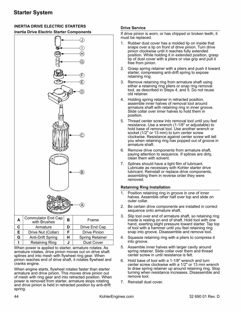
Starter System
44 32 690 01 Rev. DKohlerEngines.com
INERTIA DRIVE ELECTRIC STARTERSInertia Drive Electric Starter Components
A
B
C
D
E
F
G
HI
J
A Commutator End Cap with Brushes B Frame
C Armature D Drive End CapE Drive Nut (Collar) F Drive PinionG Anti-Drift Spring H Spring RetainerI Retaining Ring J Dust Cover
When power is applied to starter, armature rotates. As armature rotates, drive pinion moves out on drive shaft splines and into mesh with flywheel ring gear. When pinion reaches end of drive shaft, it rotates flywheel and cranks engine.When engine starts, flywheel rotates faster than starter armature and drive pinion. This moves drive pinion out of mesh with ring gear and into retracted position. When power is removed from starter, armature stops rotating and drive pinion is held in retracted position by anti-drift spring.
Drive ServiceIf drive pinion is worn, or has chipped or broken teeth, it must be replaced.1. Rubber dust cover has a molded lip on inside that
snaps over a lip on front of drive pinion. Turn drive pinion clockwise until it reaches fully extended position. While holding it in extended position, grasp tip of dust cover with a pliers or vise grip and pull it free from pinion.
2. Grasp spring retainer with a pliers and push it toward starter, compressing anti-drift spring to expose retaining ring.
3. Remove retaining ring from armature shaft using either a retaining ring pliers or snap ring removal tool, as described in Steps 4, and 5. Do not reuse old retainer.
4. Holding spring retainer in retracted position, assemble inner halves of removal tool around armature shaft with retaining ring in inner groove. Slide collar over inner halves to hold them in position.
5. Thread center screw into removal tool until you feel resistance. Use a wrench (1-1/8" or adjustable) to hold base of removal tool. Use another wrench or socket (1/2" or 13 mm) to turn center screw clockwise. Resistance against center screw will tell you when retaining ring has popped out of groove in armature shaft.
6. Remove drive components from armature shaft, paying attention to sequence. If splines are dirty, clean them with solvent.
7. Splines should have a light film of lubricant. Lubricate as necessary with Kohler starter drive lubricant. Reinstall or replace drive components, assembling them in reverse order they were removed.
Retaining Ring Installation1. Position retaining ring in groove in one of inner
halves. Assemble other half over top and slide on outer collar.
2. Be certain drive components are installed in correct sequence onto armature shaft.
3. Slip tool over end of armature shaft, so retaining ring inside is resting on end of shaft. Hold tool with one hand, exerting slight pressure toward starter. Tap top of tool with a hammer until you feel retaining ring snap into groove. Disassemble and remove tool.
4. Squeeze retaining ring with a pliers to compress it into groove.
5. Assemble inner halves with larger cavity around spring retainer. Slide collar over them and thread center screw in until resistance is felt.
6. Hold base of tool with a 1-1/8" wrench and turn center screw clockwise with a 1/2" or 13 mm wrench to draw spring retainer up around retaining ring. Stop turning when resistance increases. Disassemble and remove tool.
7. Reinstall dust cover.
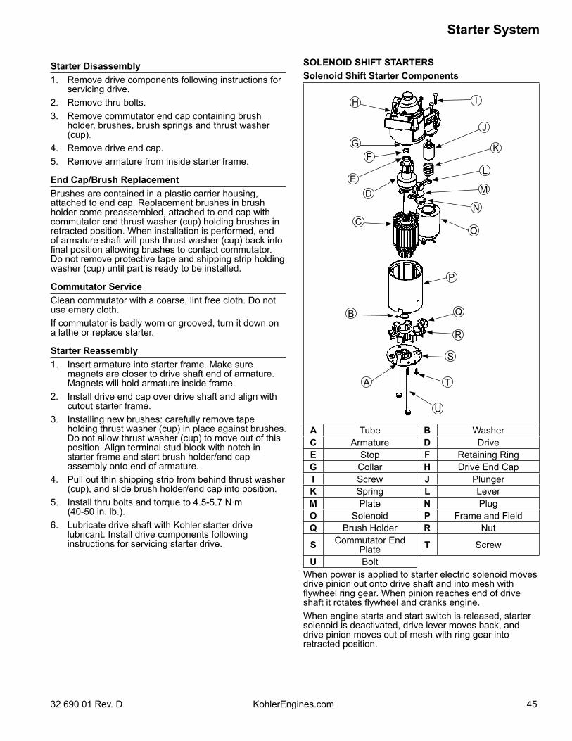
Starter System
4532 690 01 Rev. D KohlerEngines.com
Starter Disassembly1. Remove drive components following instructions for
servicing drive.2. Remove thru bolts.3. Remove commutator end cap containing brush
holder, brushes, brush springs and thrust washer (cup).
4. Remove drive end cap.5. Remove armature from inside starter frame.
End Cap/Brush ReplacementBrushes are contained in a plastic carrier housing, attached to end cap. Replacement brushes in brush holder come preassembled, attached to end cap with commutator end thrust washer (cup) holding brushes in retracted position. When installation is performed, end of armature shaft will push thrust washer (cup) back into final position allowing brushes to contact commutator. Do not remove protective tape and shipping strip holding washer (cup) until part is ready to be installed.
Commutator ServiceClean commutator with a coarse, lint free cloth. Do not use emery cloth.If commutator is badly worn or grooved, turn it down on a lathe or replace starter.
Starter Reassembly1. Insert armature into starter frame. Make sure
magnets are closer to drive shaft end of armature. Magnets will hold armature inside frame.
2. Install drive end cap over drive shaft and align with cutout starter frame.
3. Installing new brushes: carefully remove tape holding thrust washer (cup) in place against brushes. Do not allow thrust washer (cup) to move out of this position. Align terminal stud block with notch in starter frame and start brush holder/end cap assembly onto end of armature.
4. Pull out thin shipping strip from behind thrust washer (cup), and slide brush holder/end cap into position.
5. Install thru bolts and torque to 4.5-5.7 N·m (40-50 in. lb.).
6. Lubricate drive shaft with Kohler starter drive lubricant. Install drive components following instructions for servicing starter drive.
SOLENOID SHIFT STARTERSSolenoid Shift Starter Components
A
B
U
T
S
R
Q
P
O
N
M
L
K
J
IH
GF
ED
C
A Tube B WasherC Armature D DriveE Stop F Retaining RingG Collar H Drive End CapI Screw J PlungerK Spring L LeverM Plate N PlugO Solenoid P Frame and FieldQ Brush Holder R Nut
S Commutator EndPlate T Screw
U BoltWhen power is applied to starter electric solenoid moves drive pinion out onto drive shaft and into mesh with flywheel ring gear. When pinion reaches end of drive shaft it rotates flywheel and cranks engine.When engine starts and start switch is released, starter solenoid is deactivated, drive lever moves back, and drive pinion moves out of mesh with ring gear into retracted position.
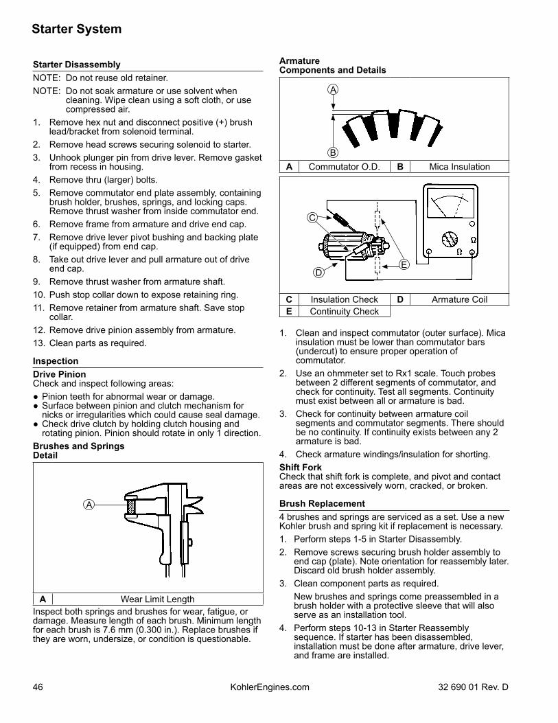
Starter System
46 32 690 01 Rev. DKohlerEngines.com
Starter DisassemblyNOTE: Do not reuse old retainer.NOTE: Do not soak armature or use solvent when
cleaning. Wipe clean using a soft cloth, or use compressed air.
1. Remove hex nut and disconnect positive (+) brush lead/bracket from solenoid terminal.
2. Remove head screws securing solenoid to starter.3. Unhook plunger pin from drive lever. Remove gasket
from recess in housing.4. Remove thru (larger) bolts.5. Remove commutator end plate assembly, containing
brush holder, brushes, springs, and locking caps. Remove thrust washer from inside commutator end.
6. Remove frame from armature and drive end cap.7. Remove drive lever pivot bushing and backing plate
(if equipped) from end cap.8. Take out drive lever and pull armature out of drive
end cap.9. Remove thrust washer from armature shaft.10. Push stop collar down to expose retaining ring.11. Remove retainer from armature shaft. Save stop
collar.12. Remove drive pinion assembly from armature.13. Clean parts as required.
InspectionDrive PinionCheck and inspect following areas:● Pinion teeth for abnormal wear or damage.● Surface between pinion and clutch mechanism for
nicks or irregularities which could cause seal damage.● Check drive clutch by holding clutch housing and
rotating pinion. Pinion should rotate in only 1 direction.Brushes and SpringsDetail
A
A Wear Limit LengthInspect both springs and brushes for wear, fatigue, or damage. Measure length of each brush. Minimum length for each brush is 7.6 mm (0.300 in.). Replace brushes if they are worn, undersize, or condition is questionable.
ArmatureComponents and Details
A
BA Commutator O.D. B Mica Insulation
DE
C
C Insulation Check D Armature CoilE Continuity Check
1. Clean and inspect commutator (outer surface). Mica insulation must be lower than commutator bars (undercut) to ensure proper operation of commutator.
2. Use an ohmmeter set to Rx1 scale. Touch probes between 2 different segments of commutator, and check for continuity. Test all segments. Continuity must exist between all or armature is bad.
3. Check for continuity between armature coil segments and commutator segments. There should be no continuity. If continuity exists between any 2 armature is bad.
4. Check armature windings/insulation for shorting.Shift ForkCheck that shift fork is complete, and pivot and contact areas are not excessively worn, cracked, or broken.
Brush Replacement4 brushes and springs are serviced as a set. Use a new Kohler brush and spring kit if replacement is necessary.1. Perform steps 1-5 in Starter Disassembly.2. Remove screws securing brush holder assembly to
end cap (plate). Note orientation for reassembly later. Discard old brush holder assembly.
3. Clean component parts as required. New brushes and springs come preassembled in a
brush holder with a protective sleeve that will also serve as an installation tool.
4. Perform steps 10-13 in Starter Reassembly sequence. If starter has been disassembled, installation must be done after armature, drive lever, and frame are installed.
Starter System
4732 690 01 Rev. D KohlerEngines.com
Starter ReassemblyNOTE: Always use a new retainer. Do not reuse old
retainers that have been removed.NOTE: Correctly installed, center pivot section of drive
lever will be flush or below machined surface of housing.
1. Apply drive lubricant to armature shaft splines. Install drive pinion onto armature shaft.
2. Install and assemble stop collar/retainer assembly. a. Install stop collar down onto armature shaft with
counter bore (recess) up. b. Install a new retainer in larger (rear) groove of
armature shaft. Squeeze with a pliers to compress it in groove.
c. Slide stop collar up and lock it into place, so recess surrounds retainer in groove. If necessary, rotate pinion outward on armature splines against retainer to help seat collar around retainer.
3. Install offset thrust (stop) washer so smaller offset of washer faces retainer/collar.
4. Apply a small amount of oil to bearing in drive end cap, and install armature with drive pinion.
5. Lubricate fork end and center pivot of drive lever with drive lubricant. Position fork end into space between captured washer and rear of pinion.
6. Slide armature into drive end cap and at same time seat drive lever into housing.
7. Install rubber grommet into matching recess of drive end cap. Molded recesses in grommet should be out, matching and aligned with those in end cap.
8. Install frame, with small notch forward, onto armature and drive end cap. Align notch with corresponding section in rubber grommet. Install drain tube in rear cutout, if it was removed previously.
9. Install flat thrust washer onto commutator end of armature shaft.
10. Starter reassembly when replacing brushes/brush holder assembly:
a. Hold starter assembly vertically on end housing, and carefully position assembled brush holder assembly, with supplied protective tube, against end of commutator/armature. Mounting screw holes in metal clips must be up/out. Slide brush holder assembly down into place around commutator, and install positive (+) brush lead grommet in cutout of frame. Protective tube may be saved and used for future servicing.
Starter reassembly when not replacing brushes/brush holder assembly:
a. Carefully unhook retaining caps from brush assemblies. Do not lose springs.
b. Position brushes back in their slots so they are flush with I.D. of brush holder assembly. Insert brush installation tool (with extension), or use tube described above from a prior brush installation, through brush holder assembly, so holes in metal mounting clips are up/out.
c. Install brush springs and snap on retainer caps. d. Hold starter assembly vertically on end housing,
and carefully place tool (with extension) and assembled original brush holder assembly onto end of armature shaft. Slide brush holder assembly down into place around commutator, install positive (+) brush lead grommet in cutout of frame.
11. Install end cap onto armature and frame, aligning thin raised rib in end cap with corresponding slot in grommet of positive (+) brush lead.
12. Install thru bolts and brush holder mounting screws. Torque bolts to 5.6-9.0 N·m (49-79 in. lb.) and brush holder mounting screws to 2.5-3.3 N·m (22-29 in. lb.).
13. Hook plunger behind upper end of drive lever and install spring into solenoid. Insert mounting screws through holes in drive end cap. Use these to hold solenoid gasket in position, then mount solenoid. Torque screws to 4.0-6.0 N·m (35-53 in. lb.).
14. Connect positive (+) brush lead/bracket to solenoid and secure with nut. Torque nut to 8-11 N·m (71-97 in. lb.). Do not overtighten.
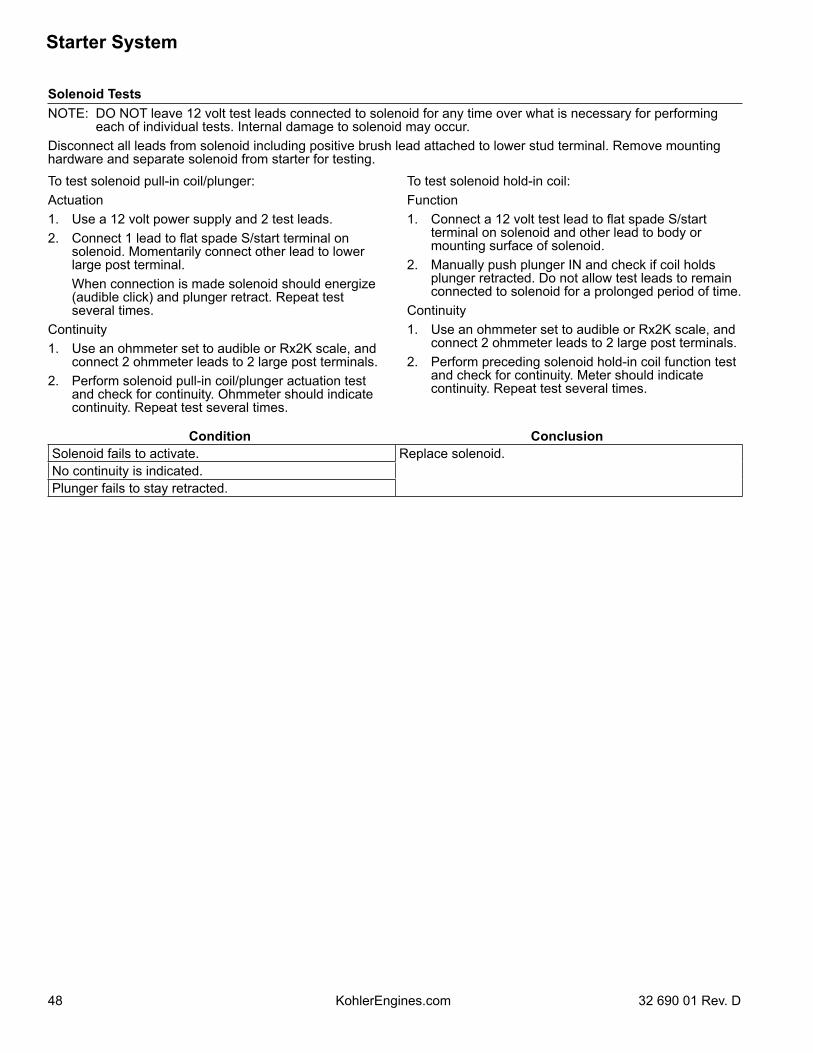
Starter System
48 32 690 01 Rev. DKohlerEngines.com
Solenoid TestsNOTE: DO NOT leave 12 volt test leads connected to solenoid for any time over what is necessary for performing
each of individual tests. Internal damage to solenoid may occur.Disconnect all leads from solenoid including positive brush lead attached to lower stud terminal. Remove mounting hardware and separate solenoid from starter for testing.To test solenoid pull-in coil/plunger:Actuation1. Use a 12 volt power supply and 2 test leads.2. Connect 1 lead to flat spade S/start terminal on
solenoid. Momentarily connect other lead to lower large post terminal.
When connection is made solenoid should energize (audible click) and plunger retract. Repeat test several times.
Continuity1. Use an ohmmeter set to audible or Rx2K scale, and
connect 2 ohmmeter leads to 2 large post terminals.2. Perform solenoid pull-in coil/plunger actuation test
and check for continuity. Ohmmeter should indicate continuity. Repeat test several times.
To test solenoid hold-in coil:Function1. Connect a 12 volt test lead to flat spade S/start
terminal on solenoid and other lead to body or mounting surface of solenoid.
2. Manually push plunger IN and check if coil holds plunger retracted. Do not allow test leads to remain connected to solenoid for a prolonged period of time.
Continuity1. Use an ohmmeter set to audible or Rx2K scale, and
connect 2 ohmmeter leads to 2 large post terminals. 2. Perform preceding solenoid hold-in coil function test
and check for continuity. Meter should indicate continuity. Repeat test several times.
Condition ConclusionSolenoid fails to activate. Replace solenoid.No continuity is indicated.Plunger fails to stay retracted.
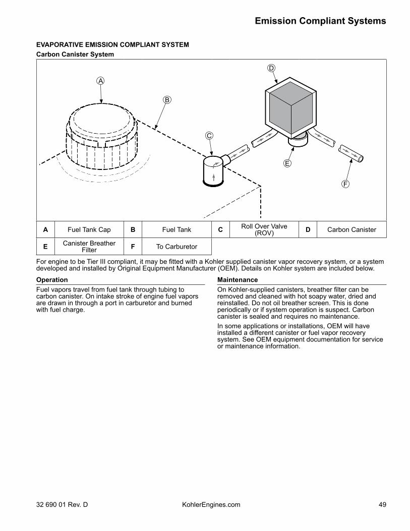
49
Emission Compliant Systems
32 690 01 Rev. D KohlerEngines.com
EVAPORATIVE EMISSION COMPLIANT SYSTEMCarbon Canister System
A Fuel Tank Cap B Fuel Tank C Roll Over Valve(ROV) D Carbon Canister
E Canister Breather Filter F To Carburetor
A
B
C
D
E
F
OperationFuel vapors travel from fuel tank through tubing to carbon canister. On intake stroke of engine fuel vapors are drawn in through a port in carburetor and burned with fuel charge.
MaintenanceOn Kohler-supplied canisters, breather filter can be removed and cleaned with hot soapy water, dried and reinstalled. Do not oil breather screen. This is done periodically or if system operation is suspect. Carbon canister is sealed and requires no maintenance.In some applications or installations, OEM will have installed a different canister or fuel vapor recovery system. See OEM equipment documentation for service or maintenance information.
For engine to be Tier III compliant, it may be fitted with a Kohler supplied canister vapor recovery system, or a system developed and installed by Original Equipment Manufacturer (OEM). Details on Kohler system are included below.
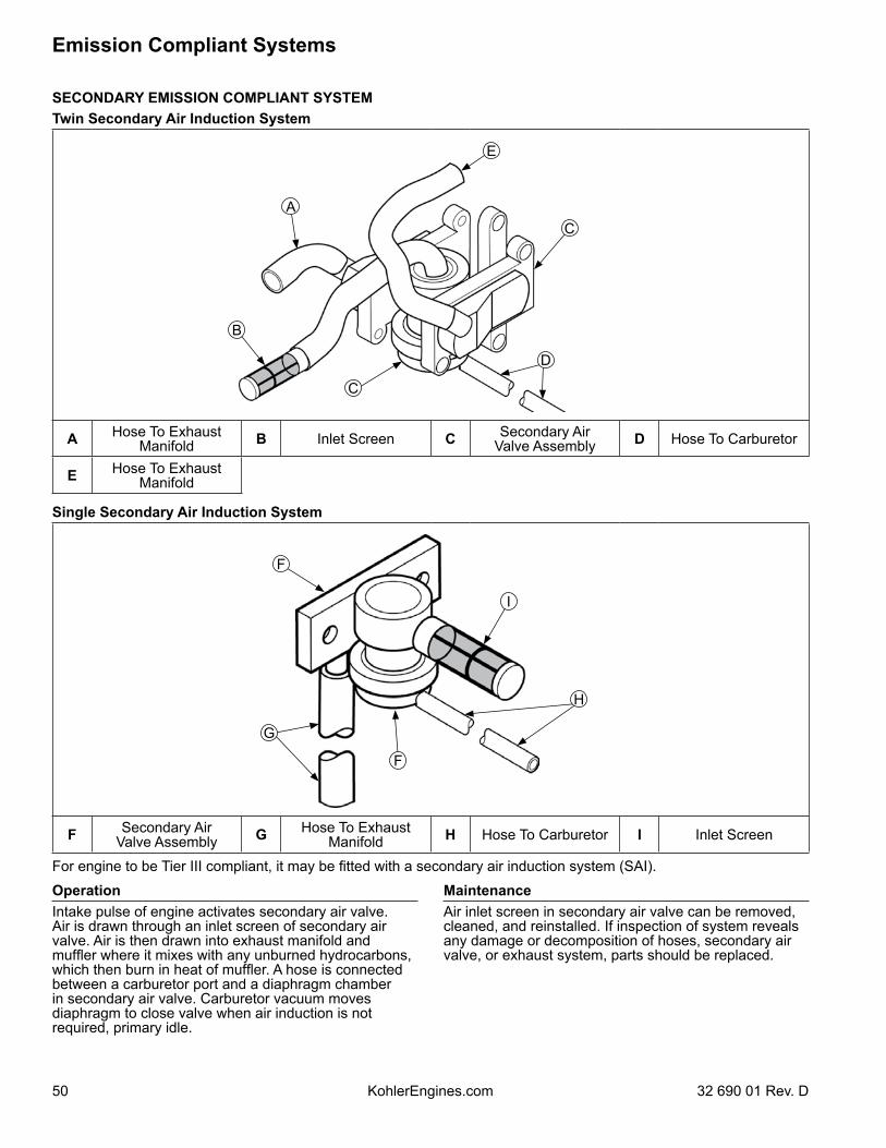
50
Emission Compliant Systems
KohlerEngines.com 32 690 01 Rev. D
SECONDARY EMISSION COMPLIANT SYSTEMTwin Secondary Air Induction System
A Hose To ExhaustManifold B Inlet Screen C Secondary Air
Valve Assembly D Hose To Carburetor
E Hose To ExhaustManifold
Single Secondary Air Induction System
F Secondary Air Valve Assembly G Hose To Exhaust
Manifold H Hose To Carburetor I Inlet Screen
A
B
C
D
C
E
F
G
F
H
I
OperationIntake pulse of engine activates secondary air valve. Air is drawn through an inlet screen of secondary air valve. Air is then drawn into exhaust manifold and muffler where it mixes with any unburned hydrocarbons, which then burn in heat of muffler. A hose is connected between a carburetor port and a diaphragm chamber in secondary air valve. Carburetor vacuum moves diaphragm to close valve when air induction is not required, primary idle.
MaintenanceAir inlet screen in secondary air valve can be removed, cleaned, and reinstalled. If inspection of system reveals any damage or decomposition of hoses, secondary air valve, or exhaust system, parts should be replaced.
For engine to be Tier III compliant, it may be fitted with a secondary air induction system (SAI).
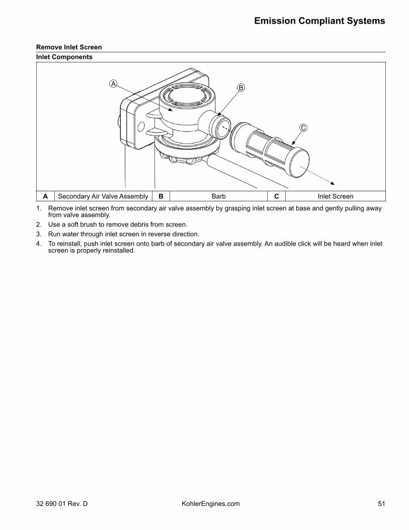
51
Emission Compliant Systems
32 690 01 Rev. D KohlerEngines.com
Remove Inlet ScreenInlet Components
A B
C
A Secondary Air Valve Assembly B Barb C Inlet Screen
1. Remove inlet screen from secondary air valve assembly by grasping inlet screen at base and gently pulling away from valve assembly.
2. Use a soft brush to remove debris from screen.3. Run water through inlet screen in reverse direction.4. To reinstall, push inlet screen onto barb of secondary air valve assembly. An audible click will be heard when inlet
screen is properly reinstalled.
52
Disassembly/Inspection and Service
KohlerEngines.com 32 690 01 Rev. D
WARNINGBefore working on engine or equipment, disable engine as follows: 1) Disconnect spark plug lead(s). 2) Disconnect negative (–) battery cable from battery.
Accidental Starts can cause severe injury or death.Disconnect and ground spark plug lead(s) before servicing.
External Engine Components
JX
E
P
G
W
V
E
E
F
H
K
I
LM N
L
O
B
A
C
D
R
Q
ST
U
A Fixed Guard B Air CleanerAccess Door C Debris Screen D Blower Housing
E Hose Clamp F Fuel Pump G Hose Clip H Fuel LineI Fuel Filter J Oil Filter K Nipple L O-Ring
M Oil Feed Tube(Oil Pump Outlet) N Oil Feed Tube
(Filter to Pan) O Outer Baffle P Electric Starter
Q Inner Baffle R Ignition Module S Intake Manifold T CarburetorU Gasket V Air Cleaner Base W Air Cleaner X Rectifier-Regulator
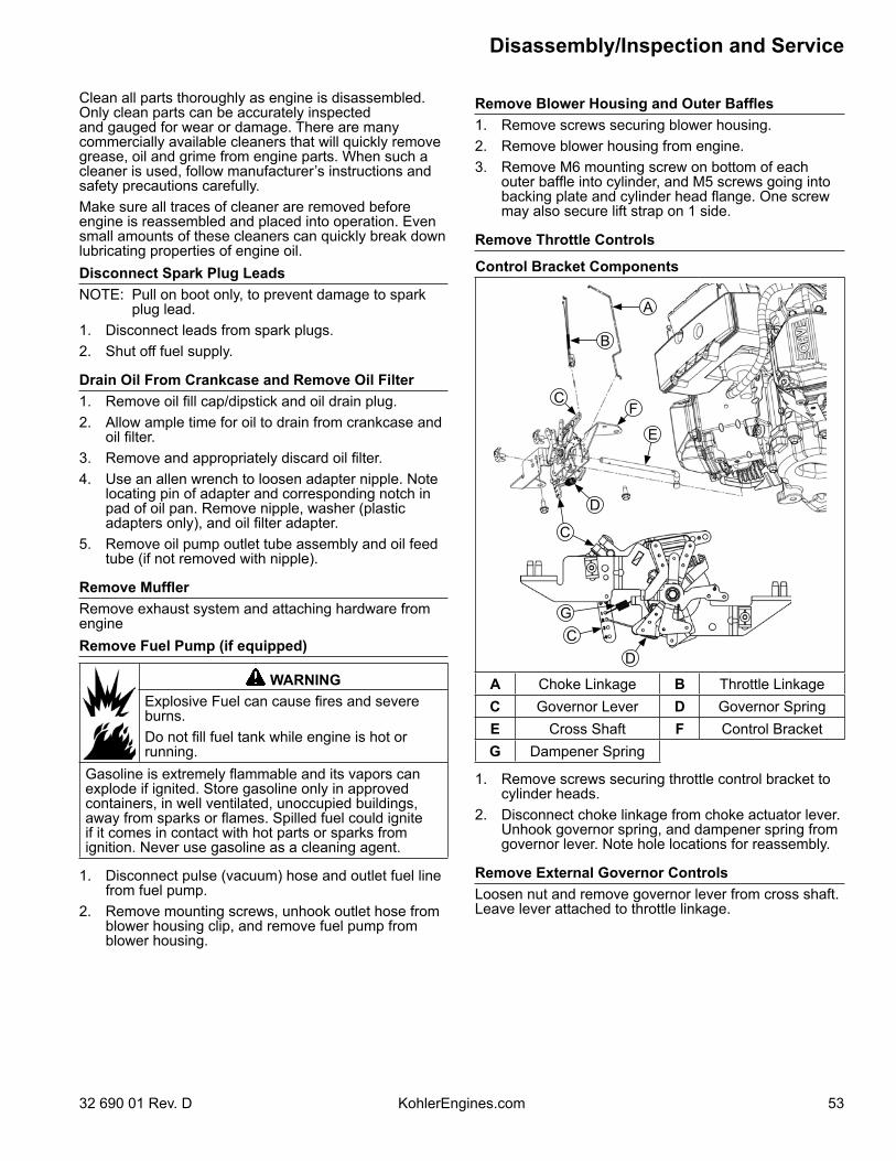
53
Disassembly/Inspection and Service
32 690 01 Rev. D KohlerEngines.com
Clean all parts thoroughly as engine is disassembled. Only clean parts can be accurately inspected and gauged for wear or damage. There are many commercially available cleaners that will quickly remove grease, oil and grime from engine parts. When such a cleaner is used, follow manufacturer’s instructions and safety precautions carefully.Make sure all traces of cleaner are removed before engine is reassembled and placed into operation. Even small amounts of these cleaners can quickly break down lubricating properties of engine oil.Disconnect Spark Plug LeadsNOTE: Pull on boot only, to prevent damage to spark
plug lead.1. Disconnect leads from spark plugs.2. Shut off fuel supply.
Drain Oil From Crankcase and Remove Oil Filter1. Remove oil fill cap/dipstick and oil drain plug.2. Allow ample time for oil to drain from crankcase and
oil filter.3. Remove and appropriately discard oil filter.4. Use an allen wrench to loosen adapter nipple. Note
locating pin of adapter and corresponding notch in pad of oil pan. Remove nipple, washer (plastic adapters only), and oil filter adapter.
5. Remove oil pump outlet tube assembly and oil feed tube (if not removed with nipple).
Remove MufflerRemove exhaust system and attaching hardware from engineRemove Fuel Pump (if equipped)
WARNINGExplosive Fuel can cause fires and severe burns.Do not fill fuel tank while engine is hot or running.
Gasoline is extremely flammable and its vapors can explode if ignited. Store gasoline only in approved containers, in well ventilated, unoccupied buildings, away from sparks or flames. Spilled fuel could ignite if it comes in contact with hot parts or sparks from ignition. Never use gasoline as a cleaning agent.
1. Disconnect pulse (vacuum) hose and outlet fuel line from fuel pump.
2. Remove mounting screws, unhook outlet hose from blower housing clip, and remove fuel pump from blower housing.
Remove Blower Housing and Outer Baffles1. Remove screws securing blower housing.2. Remove blower housing from engine.3. Remove M6 mounting screw on bottom of each
outer baffle into cylinder, and M5 screws going into backing plate and cylinder head flange. One screw may also secure lift strap on 1 side.
Remove Throttle Controls
Control Bracket Components
F
G
C
C
C
B
A
D
D
E
A Choke Linkage B Throttle LinkageC Governor Lever D Governor SpringE Cross Shaft F Control BracketG Dampener Spring
1. Remove screws securing throttle control bracket to cylinder heads.
2. Disconnect choke linkage from choke actuator lever. Unhook governor spring, and dampener spring from governor lever. Note hole locations for reassembly.
Remove External Governor ControlsLoosen nut and remove governor lever from cross shaft. Leave lever attached to throttle linkage.
54
Disassembly/Inspection and Service
KohlerEngines.com 32 690 01 Rev. D
Remove Air Cleaner and Carburetor
WARNINGExplosive Fuel can cause fires and severe burns.Do not fill fuel tank while engine is hot or running.
Gasoline is extremely flammable and its vapors can explode if ignited. Store gasoline only in approved containers, in well ventilated, unoccupied buildings, away from sparks or flames. Spilled fuel could ignite if it comes in contact with hot parts or sparks from ignition. Never use gasoline as a cleaning agent.
1. Remove carburetor/air cleaner base mounting nuts and disconnect breather hose. Remove air cleaner base and gasket.
2. Unhook retainer and remove air cleaner element and precleaner (if equipped) from air cleaner base for servicing.
3. Disconnect ground lead and fuel shut-off solenoid lead (if equipped).
4. Remove carburetor, throttle linkage and governor lever as an assembly.
5. Remove carburetor gasket.6. If necessary, carburetor, throttle linkage and
governor lever can be separated. Reattach bushings to linkage following separation to avoid losing them.
Remove Electric Starter Motor1. Disconnect leads from starter.2. Remove screws and starter.3. Pull out oil fill tube with lifting strap from crankcase.
Remove Inner BafflesRemove mounting screws securing inner baffles to crankcase. Note position of any lifting bracket(s). Remove inner baffles.
Remove Ignition Modules1. Rotate flywheel so magnet is away from modules.2. Disconnect lead(s) from each ignition module. Fixed
Timing Models and DSAI Models have 1 lead per module and DSAM or SMART-SPARK™ (variable timing) ignition modules have 2 leads per module.
3. Remove mounting screws and ignition modules. Note position of ignition modules.
Remove Intake Manifold and Rectifier-Regulator1. Remove screws securing intake manifold to cylinder
heads. Note which screws hold wiring clamp(s).2. Remove intake manifold and O-rings. Leave wiring
harness attached to manifold.3. Remove screws securing rectifier-regulator to
backing plate and disconnect plug.4. Use tip of a small screwdriver or similar small flat
tool to bend locking tang, then remove B+ (center lead) from terminal plug. This will allow intake manifold to be removed with wiring harness intact.
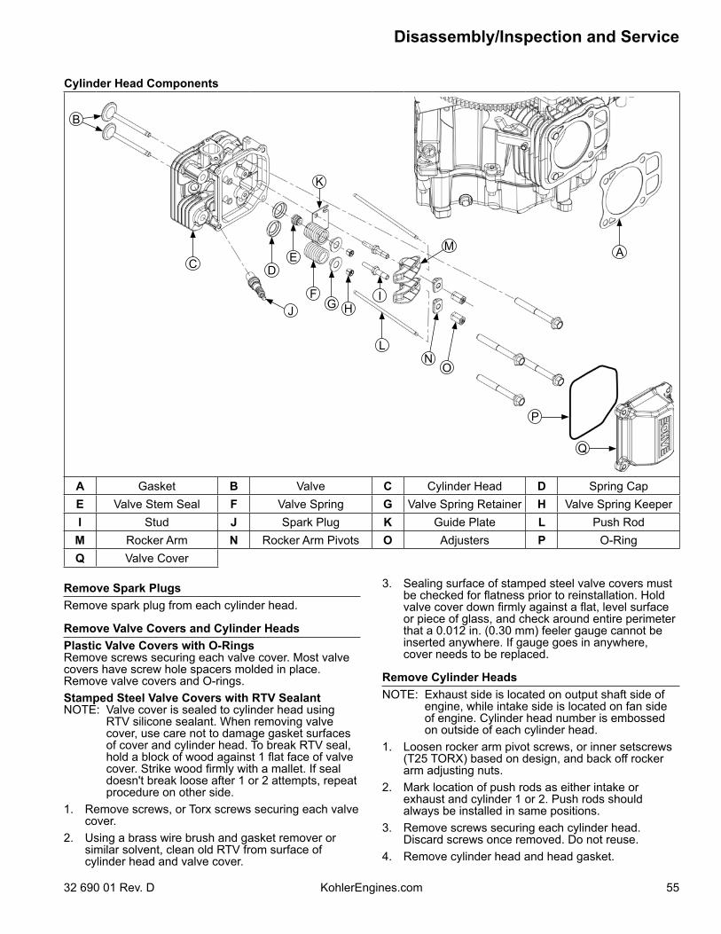
55
Disassembly/Inspection and Service
32 690 01 Rev. D KohlerEngines.com
Remove Spark PlugsRemove spark plug from each cylinder head.
Remove Valve Covers and Cylinder HeadsPlastic Valve Covers with O-RingsRemove screws securing each valve cover. Most valve covers have screw hole spacers molded in place. Remove valve covers and O-rings.Stamped Steel Valve Covers with RTV SealantNOTE: Valve cover is sealed to cylinder head using
RTV silicone sealant. When removing valve cover, use care not to damage gasket surfaces of cover and cylinder head. To break RTV seal, hold a block of wood against 1 flat face of valve cover. Strike wood firmly with a mallet. If seal doesn't break loose after 1 or 2 attempts, repeat procedure on other side.
1. Remove screws, or Torx screws securing each valve cover.
2. Using a brass wire brush and gasket remover or similar solvent, clean old RTV from surface of cylinder head and valve cover.
Cylinder Head Components
A
B
DC
J
E
FH
IG
L
M
NO
K
P
Q
A Gasket B Valve C Cylinder Head D Spring CapE Valve Stem Seal F Valve Spring G Valve Spring Retainer H Valve Spring KeeperI Stud J Spark Plug K Guide Plate L Push Rod
M Rocker Arm N Rocker Arm Pivots O Adjusters P O-RingQ Valve Cover
3. Sealing surface of stamped steel valve covers must be checked for flatness prior to reinstallation. Hold valve cover down firmly against a flat, level surface or piece of glass, and check around entire perimeter that a 0.012 in. (0.30 mm) feeler gauge cannot be inserted anywhere. If gauge goes in anywhere, cover needs to be replaced.
Remove Cylinder HeadsNOTE: Exhaust side is located on output shaft side of
engine, while intake side is located on fan side of engine. Cylinder head number is embossed on outside of each cylinder head.
1. Loosen rocker arm pivot screws, or inner setscrews (T25 TORX) based on design, and back off rocker arm adjusting nuts.
2. Mark location of push rods as either intake or exhaust and cylinder 1 or 2. Push rods should always be installed in same positions.
3. Remove screws securing each cylinder head. Discard screws once removed. Do not reuse.
4. Remove cylinder head and head gasket.
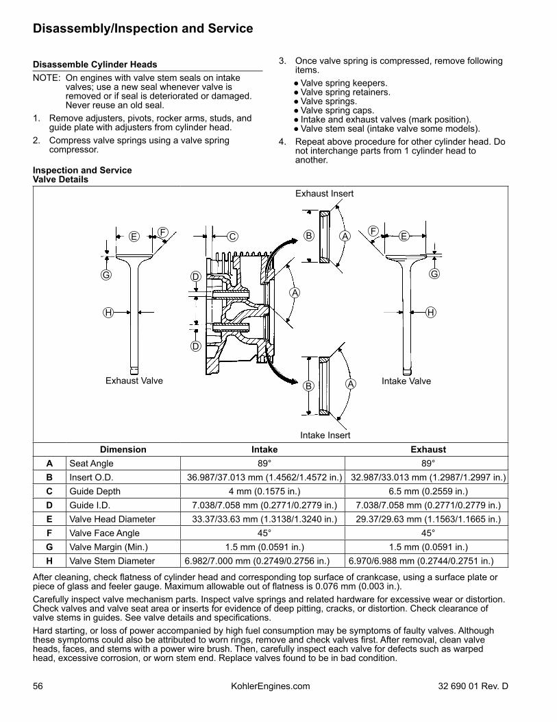
56
Disassembly/Inspection and Service
KohlerEngines.com 32 690 01 Rev. D
Disassemble Cylinder HeadsNOTE: On engines with valve stem seals on intake
valves; use a new seal whenever valve is removed or if seal is deteriorated or damaged. Never reuse an old seal.
1. Remove adjusters, pivots, rocker arms, studs, and guide plate with adjusters from cylinder head.
2. Compress valve springs using a valve spring compressor.
3. Once valve spring is compressed, remove following items.
● Valve spring keepers. ● Valve spring retainers. ● Valve springs. ● Valve spring caps. ● Intake and exhaust valves (mark position). ● Valve stem seal (intake valve some models).
4. Repeat above procedure for other cylinder head. Do not interchange parts from 1 cylinder head to another.
Inspection and ServiceValve Details
H
EFAC
D
FE
G
A
H
D
AB
B
G
Intake ValveExhaust Valve
Intake Insert
Exhaust Insert
Dimension Intake ExhaustA Seat Angle 89° 89°B Insert O.D. 36.987/37.013 mm (1.4562/1.4572 in.) 32.987/33.013 mm (1.2987/1.2997 in.)C Guide Depth 4 mm (0.1575 in.) 6.5 mm (0.2559 in.)D Guide I.D. 7.038/7.058 mm (0.2771/0.2779 in.) 7.038/7.058 mm (0.2771/0.2779 in.)E Valve Head Diameter 33.37/33.63 mm (1.3138/1.3240 in.) 29.37/29.63 mm (1.1563/1.1665 in.)F Valve Face Angle 45° 45°G Valve Margin (Min.) 1.5 mm (0.0591 in.) 1.5 mm (0.0591 in.)H Valve Stem Diameter 6.982/7.000 mm (0.2749/0.2756 in.) 6.970/6.988 mm (0.2744/0.2751 in.)
After cleaning, check flatness of cylinder head and corresponding top surface of crankcase, using a surface plate or piece of glass and feeler gauge. Maximum allowable out of flatness is 0.076 mm (0.003 in.).Carefully inspect valve mechanism parts. Inspect valve springs and related hardware for excessive wear or distortion. Check valves and valve seat area or inserts for evidence of deep pitting, cracks, or distortion. Check clearance of valve stems in guides. See valve details and specifications.Hard starting, or loss of power accompanied by high fuel consumption may be symptoms of faulty valves. Although these symptoms could also be attributed to worn rings, remove and check valves first. After removal, clean valve heads, faces, and stems with a power wire brush. Then, carefully inspect each valve for defects such as warped head, excessive corrosion, or worn stem end. Replace valves found to be in bad condition.
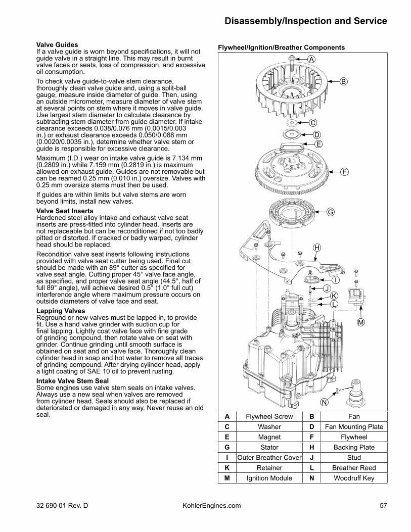
57
Disassembly/Inspection and Service
32 690 01 Rev. D KohlerEngines.com
Valve GuidesIf a valve guide is worn beyond specifications, it will not guide valve in a straight line. This may result in burnt valve faces or seats, loss of compression, and excessive oil consumption.To check valve guide-to-valve stem clearance, thoroughly clean valve guide and, using a split-ball gauge, measure inside diameter of guide. Then, using an outside micrometer, measure diameter of valve stem at several points on stem where it moves in valve guide. Use largest stem diameter to calculate clearance by subtracting stem diameter from guide diameter. If intake clearance exceeds 0.038/0.076 mm (0.0015/0.003 in.) or exhaust clearance exceeds 0.050/0.088 mm (0.0020/0.0035 in.), determine whether valve stem or guide is responsible for excessive clearance.Maximum (I.D.) wear on intake valve guide is 7.134 mm (0.2809 in.) while 7.159 mm (0.2819 in.) is maximum allowed on exhaust guide. Guides are not removable but can be reamed 0.25 mm (0.010 in.) oversize. Valves with 0.25 mm oversize stems must then be used.If guides are within limits but valve stems are worn beyond limits, install new valves.Valve Seat InsertsHardened steel alloy intake and exhaust valve seat inserts are press-fitted into cylinder head. Inserts are not replaceable but can be reconditioned if not too badly pitted or distorted. If cracked or badly warped, cylinder head should be replaced.Recondition valve seat inserts following instructions provided with valve seat cutter being used. Final cut should be made with an 89° cutter as specified for valve seat angle. Cutting proper 45° valve face angle, as specified, and proper valve seat angle (44.5°, half of full 89° angle), will achieve desired 0.5° (1.0° full cut) interference angle where maximum pressure occurs on outside diameters of valve face and seat.Lapping ValvesReground or new valves must be lapped in, to provide fit. Use a hand valve grinder with suction cup for final lapping. Lightly coat valve face with fine grade of grinding compound, then rotate valve on seat with grinder. Continue grinding until smooth surface is obtained on seat and on valve face. Thoroughly clean cylinder head in soap and hot water to remove all traces of grinding compound. After drying cylinder head, apply a light coating of SAE 10 oil to prevent rusting.Intake Valve Stem SealSome engines use valve stem seals on intake valves. Always use a new seal when valves are removed from cylinder head. Seals should also be replaced if deteriorated or damaged in any way. Never reuse an old seal.
Flywheel/Ignition/Breather Components
I
KL
J
M
F
G
H
C
B
A
DE
N
A Flywheel Screw B FanC Washer D Fan Mounting PlateE Magnet F FlywheelG Stator H Backing PlateI Outer Breather Cover J StudK Retainer L Breather ReedM Ignition Module N Woodruff Key
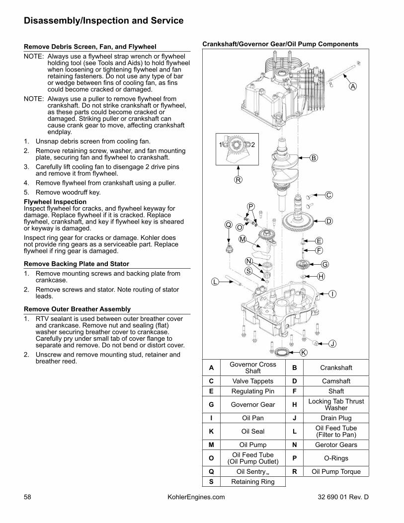
58
Disassembly/Inspection and Service
KohlerEngines.com 32 690 01 Rev. D
Remove Debris Screen, Fan, and FlywheelNOTE: Always use a flywheel strap wrench or flywheel
holding tool (see Tools and Aids) to hold flywheel when loosening or tightening flywheel and fan retaining fasteners. Do not use any type of bar or wedge between fins of cooling fan, as fins could become cracked or damaged.
NOTE: Always use a puller to remove flywheel from crankshaft. Do not strike crankshaft or flywheel, as these parts could become cracked or damaged. Striking puller or crankshaft can cause crank gear to move, affecting crankshaft endplay.
1. Unsnap debris screen from cooling fan.2. Remove retaining screw, washer, and fan mounting
plate, securing fan and flywheel to crankshaft.3. Carefully lift cooling fan to disengage 2 drive pins
and remove it from flywheel.4. Remove flywheel from crankshaft using a puller.5. Remove woodruff key.Flywheel InspectionInspect flywheel for cracks, and flywheel keyway for damage. Replace flywheel if it is cracked. Replace flywheel, crankshaft, and key if flywheel key is sheared or keyway is damaged.Inspect ring gear for cracks or damage. Kohler does not provide ring gears as a serviceable part. Replace flywheel if ring gear is damaged.
Remove Backing Plate and Stator1. Remove mounting screws and backing plate from
crankcase.2. Remove screws and stator. Note routing of stator
leads.
Remove Outer Breather Assembly1. RTV sealant is used between outer breather cover
and crankcase. Remove nut and sealing (flat) washer securing breather cover to crankcase. Carefully pry under small tab of cover flange to separate and remove. Do not bend or distort cover.
2. Unscrew and remove mounting stud, retainer and breather reed.
Crankshaft/Governor Gear/Oil Pump Components
KJ
L
OQ
P
R
G
H
I
D
C
B
A
EF
M
N
1 2
S
A Governor Cross Shaft B Crankshaft
C Valve Tappets D CamshaftE Regulating Pin F Shaft
G Governor Gear H Locking Tab Thrust Washer
I Oil Pan J Drain Plug
K Oil Seal L Oil Feed Tube(Filter to Pan)
M Oil Pump N Gerotor Gears
O Oil Feed Tube(Oil Pump Outlet) P O-Rings
Q Oil Sentry™ R Oil Pump TorqueS Retaining Ring
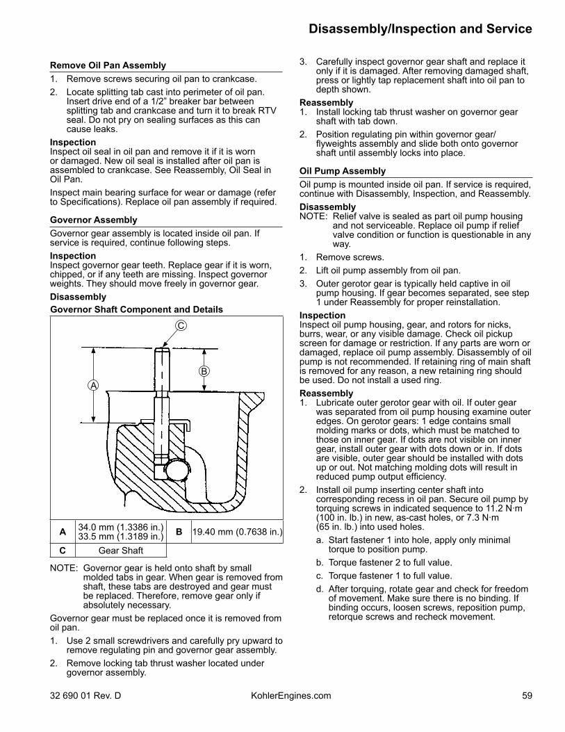
59
Disassembly/Inspection and Service
32 690 01 Rev. D KohlerEngines.com
Remove Oil Pan Assembly1. Remove screws securing oil pan to crankcase.2. Locate splitting tab cast into perimeter of oil pan.
Insert drive end of a 1/2” breaker bar between splitting tab and crankcase and turn it to break RTV seal. Do not pry on sealing surfaces as this can cause leaks.
InspectionInspect oil seal in oil pan and remove it if it is worn or damaged. New oil seal is installed after oil pan is assembled to crankcase. See Reassembly, Oil Seal in Oil Pan.Inspect main bearing surface for wear or damage (refer to Specifications). Replace oil pan assembly if required.
Governor AssemblyGovernor gear assembly is located inside oil pan. If service is required, continue following steps.InspectionInspect governor gear teeth. Replace gear if it is worn, chipped, or if any teeth are missing. Inspect governor weights. They should move freely in governor gear.DisassemblyGovernor Shaft Component and Details
C
AB
A 34.0 mm (1.3386 in.)33.5 mm (1.3189 in.) B 19.40 mm (0.7638 in.)
C Gear Shaft
NOTE: Governor gear is held onto shaft by small molded tabs in gear. When gear is removed from shaft, these tabs are destroyed and gear must be replaced. Therefore, remove gear only if absolutely necessary.
Governor gear must be replaced once it is removed from oil pan.1. Use 2 small screwdrivers and carefully pry upward to
remove regulating pin and governor gear assembly.2. Remove locking tab thrust washer located under
governor assembly.
3. Carefully inspect governor gear shaft and replace it only if it is damaged. After removing damaged shaft, press or lightly tap replacement shaft into oil pan to depth shown.
Reassembly1. Install locking tab thrust washer on governor gear
shaft with tab down.2. Position regulating pin within governor gear/
flyweights assembly and slide both onto governor shaft until assembly locks into place.
Oil Pump AssemblyOil pump is mounted inside oil pan. If service is required, continue with Disassembly, Inspection, and Reassembly.DisassemblyNOTE: Relief valve is sealed as part oil pump housing
and not serviceable. Replace oil pump if relief valve condition or function is questionable in any way.
1. Remove screws.2. Lift oil pump assembly from oil pan. 3. Outer gerotor gear is typically held captive in oil
pump housing. If gear becomes separated, see step 1 under Reassembly for proper reinstallation.
InspectionInspect oil pump housing, gear, and rotors for nicks, burrs, wear, or any visible damage. Check oil pickup screen for damage or restriction. If any parts are worn or damaged, replace oil pump assembly. Disassembly of oil pump is not recommended. If retaining ring of main shaft is removed for any reason, a new retaining ring should be used. Do not install a used ring.Reassembly1. Lubricate outer gerotor gear with oil. If outer gear
was separated from oil pump housing examine outer edges. On gerotor gears: 1 edge contains small molding marks or dots, which must be matched to those on inner gear. If dots are not visible on inner gear, install outer gear with dots down or in. If dots are visible, outer gear should be installed with dots up or out. Not matching molding dots will result in reduced pump output efficiency.
2. Install oil pump inserting center shaft into corresponding recess in oil pan. Secure oil pump by torquing screws in indicated sequence to 11.2 N·m (100 in. lb.) in new, as-cast holes, or 7.3 N·m (65 in. lb.) into used holes.
a. Start fastener 1 into hole, apply only minimal torque to position pump.
b. Torque fastener 2 to full value. c. Torque fastener 1 to full value. d. After torquing, rotate gear and check for freedom
of movement. Make sure there is no binding. If binding occurs, loosen screws, reposition pump, retorque screws and recheck movement.
60
Disassembly/Inspection and Service
KohlerEngines.com 32 690 01 Rev. D
Remove Camshaft and Valve Tappets1. Position crankcase so flywheel side is down.
Remove camshaft and shim.2. Remove valve tappets from crankcase and mark
them by their location, as either intake or exhaust and cylinder 1 or 2. Tappets should always be reinstalled in same position.
Camshaft Inspection and ServiceCheck lobes of camshaft for wear or damage. See Specifications for minimum lift specifications. Inspect cam gear for badly worn, chipped or missing teeth. Replacement of camshaft will be necessary if any of these conditions exist.Valve Tappets InspectionCheck base surface of valve tappet(s) for wear or damage. Replace tappet(s) if condition is questionable in any way. Corresponding camshaft lobe(s) should also be checked for wear or damage. Whenever tappets are replaced, apply a liberal coating of Kohler lubricant to base of each new tappet before it is installed.
Remove Governor Cross ShaftGovernor Cross Shaft Oil Seal Details
BA
A 2.0 mm (0.0787 in.) B Governor CrossShaft Seal
1. Remove retainer and washer from governor cross shaft.
2. Remove cross shaft with small inner washer through inside of crankcase.
3. Remove governor shaft seal from crankcase.If governor cross shaft seal is damaged and/or leaks, replace it using following procedure.Remove oil seal from crankcase and replace it with a new one. Install new seal to depth shown.
Connecting Rods/Piston/Breather Components
I
G
J
F
A
B
D
C
B
E
H
A Piston Ring Set B Piston Pin RetainerC Piston D Piston Pin
E Connecting Rod F Connecting RodEnd Cap
G Breather Filter H Breather CoverGasket
I Inner BreatherCover J Oil Seal
Remove Connecting Rods with Pistons and RingsNOTE: If a carbon ridge is present at top of either
cylinder bore, use a ridge reamer tool to remove it before attempting to remove piston.
NOTE: Cylinders are numbered on crankcase. Use numbers to mark each end cap, connecting rod and piston for reassembly. Do not mix end caps and connecting rods.
1. Remove screws securing closest connecting rod end cap. Remove end cap.
2. Carefully remove connecting rod and piston assembly from cylinder bore.
3. Repeat above procedure for other connecting rod and piston assembly.
61
Disassembly/Inspection and Service
32 690 01 Rev. D KohlerEngines.com
Connecting RodsOffset, stepped-cap connecting rods are used in all these engines.Inspection and ServiceCheck bearing area (big end) for excessive wear, score marks, running and side clearances (See Specifications). Replace rod and cap if scored or excessively worn.Service replacement connecting rods are available in STD size and 0.25 mm (0.010 in.) undersize. Undersized rods, 0.25 mm (0.010 in.), have an identification marking on lower end of rod shank. Always refer to appropriate parts information to ensure correct replacements are used.
Piston and RingsInspectionPiston and Rings Components and Details
A
B
C
D
E
F
G
I
H
A Piston Ring B End GapC Identification Mark D Piston
E Top Compression Ring F Center
Compression RingG Rails H Expander
I Oil Control Ring(3 Piece)
Scuffing and scoring of pistons and cylinder walls occurs when internal engine temperatures approach welding point of piston. Temperatures high enough to do this are created by friction, which is usually attributed to improper lubrication and/or overheating of engine.Normally, very little wear takes place in piston boss-piston pin area. If original piston and connecting rod can be reused after new rings are installed, original pin can also be reused but new piston pin retainers are required.
A piston pin is included as part of piston assembly – if pin boss in piston or pin are worn or damaged, a new piston assembly is required.Ring failure is usually indicated by excessive oil consumption and blue exhaust smoke. When rings fail, oil is allowed to enter combustion chamber where it is burned along with fuel. High oil consumption can also occur when piston ring end gap is incorrect because ring cannot properly conform to cylinder wall under this condition. Oil control is also lost when ring gaps are not staggered during installation.When cylinder temperatures get too high, lacquer and varnish collect on pistons causing rings to stick, which results in rapid wear. A worn ring usually takes on a shiny or bright appearance.Scratches on rings and pistons are caused by abrasive material such as carbon, dirt, or pieces of hard metal.Detonation damage occurs when a portion of fuel charge ignites spontaneously from heat and pressure shortly after ignition. This creates 2 flame fronts, which meet and explode to create extreme hammering pressures on a specific area of piston. Detonation generally occurs from using low octane fuels.Pre-ignition or ignition of fuel charge before timed spark can cause damage similar to detonation. Pre-ignition damage is often more severe than detonation damage. Pre-ignition is caused by a hot spot in combustion chamber such as glowing carbon deposits, blocked cooling fins, an improperly seated valve, or wrong spark plug(s). Replacement pistons are available in STD bore size, and 0.25 mm (0.010 in.) oversize. Replacement pistons include new piston ring sets and new piston pins.Replacement ring sets are also available separately for STD, and 0.25 mm (0.010 in.) oversize pistons. Always use new piston rings when installing pistons. Never use old rings.Some important points to remember when servicing piston rings:1. Cylinder bore must be de-glazed before service ring
sets are used.2. If cylinder bore does not need re-boring and if old
piston is within wear limits and free of score or scuff marks, old piston may be reused.
3. Remove old rings and clean up grooves. Never reuse old rings.
4. Before installing new rings on piston, place top 2 rings, each in turn, in its running area in cylinder bore and check end gap. Top and center compression ring end gap clearance is 0.25/0.56 mm (0.0100/0.0224 in.) for a new bore, or 0.94 mm (0.037 in.) for a used bore.
5. After installing new compression (top and middle) rings on piston, make sure top compression ring-to-groove side clearance is 0.025/0.048 mm (0.0010/0.0019 in.) and middle compression ring-to-groove side clearance 0.015/0.037 mm (0.0006/0.0015 in.). If side clearance is greater than specified, a new piston must be used.
62
Disassembly/Inspection and Service
KohlerEngines.com 32 690 01 Rev. D
Install New Piston RingsNOTE: Rings must be installed correctly. Ring
installation instructions are usually included with new ring sets. Follow instructions carefully. Use a piston ring expander to install rings. Install bottom (oil control) ring first and top compression ring last.
To install new piston rings, proceed as follows:1. Oil control ring (bottom groove): Install expander and
then rails. Make sure ends of expander are not overlapped.
2. Middle compression ring (center groove): Install center ring using a piston ring expander tool. Make sure identification mark is up or colored dye stripe (if contained) is to left of end gap.
3. Top compression ring (top groove): Install top ring using a piston ring expander tool. Make sure identification mark is up or colored dye stripe (if contained) is left of end gap.
Remove CrankshaftCarefully pull crankshaft from crankcase.Inspection and ServiceInspect gear teeth of crankshaft. If teeth are badly worn, chipped, or some are missing, replacement of crankshaft will be necessary.Inspect crankshaft bearing surfaces for scoring, grooving, etc. Measure running clearance between crankshaft journals and their respective bearing bores. Use an inside micrometer or telescoping gauge to measure inside diameter of both bearing bores in vertical and horizontal planes. Use an outside micrometer to measure outside diameter of crankshaft main bearing journals. Subtract journal diameters from their respective bore diameters to get running clearances. Check results against values in Specifications. If running clearances are within specification, and there is no evidence of scoring, grooving, etc., no further reconditioning is necessary. If bearing surfaces are worn or damaged, crankcase and/or oil pan will need to be replaced.Inspect crankshaft keyways. If worn or chipped, replacement of crankshaft will be necessary.Inspect crankpin for score marks or metallic pickup. Slight score marks can be cleaned with crocus cloth soaked in oil. If wear limits are exceeded, as stated in Specifications, it will be necessary to replace crankshaft.
Remove Inner Breather AssemblyBreather system is designed to control amount of oil in head area and still maintain necessary vacuum in crankcase.When pistons move downward, crankcase gases are pushed past reed through mesh filter into intake system. Upward travel of pistons closes reed and creates a low vacuum in lower crankcase. Any oil separated out through filter drains back into crankcase.1. Remove screw securing inner breather cover and
gasket to crankcase.2. Carefully remove cover, gasket, and breather filter.
Make sure drain back hole is not plugged or restricted.
Remove Flywheel and PTO End Oil SealsRemove oil seals from crankcase and oil pan.
CrankcaseInspection and ServiceCheck all gasket surfaces to make sure they are free of gasket fragments. Gasket surfaces must also be free of deep scratches or nicks.Check cylinder bore for scoring. In severe cases, unburned fuel can cause scuffing and scoring of cylinder wall. It washes necessary lubricating oils off piston and cylinder wall. As raw fuel seeps down cylinder wall, piston rings make metal to metal contact with wall. Scoring of cylinder wall can also be caused by localized hot spots resulting from blocked cooling fins or from inadequate or contaminated lubrication.If cylinder bore is badly scored, excessively worn, tapered, or out-of-round, resizing is necessary. Use an inside micrometer to determine amount of wear (refer to Specifications). A 0.25 mm (0.010 in.) oversize piston is available if resizing is selected. Initially, resize using a boring bar, then use these following procedures for honing cylinder.HoningDetails
A 23°-33° Crosshatch
A
NOTE: Kohler pistons are custom-machined to exacting tolerances. When over-sizing a cylinder, it should be machined exactly 0.25 mm (0.010 in.) over new diameter (refer to Specifications). Oversize Kohler replacement piston will then fit correctly.
While most commercially available cylinder hones can be used with either portable drills or drill presses, use of a low speed drill press is preferred as it facilitates more accurate alignment of bore in relation to crankshaft crossbore. Honing is best accomplished at a drill speed of about 250 RPM and 60 strokes per minute. After installing coarse stones in hone, proceed as follows:
63
Disassembly/Inspection and Service
32 690 01 Rev. D KohlerEngines.com
1. Lower hone into bore and after centering, adjust so stones are in contact with cylinder wall. Use of a commercial cutting-cooling agent is recommended.
2. With lower edge of each stone positioned even with lowest edge of bore, start drill and honing process. Move hone up and down while resizing to prevent formation of cutting ridges. Check size frequently.
3. When bore is within 0.064 mm (0.0025 in.) of desired size, remove coarse stones and replace them with burnishing stones. Continue with burnishing stones until bore is within 0.013 mm (0.0005 in.) of desired size and then use finish stones (220-280 grit) and polish bore to its final size. A crosshatch should be observed if honing is done correctly. Crosshatch should intersect at approximately 23°-33° off horizontal. Too flat an angle could cause rings to skip and wear excessively, and too steep an angle will result in high oil consumption.
4. After resizing, check bore for roundness, taper, and size. Use an inside micrometer, telescoping gauge, or bore gauge to take measurements. These measurements should be taken at 3 locations in cylinder – at top, middle, and bottom. Two measurements should be taken (perpendicular to each other) at 3 locations.
Clean Cylinder Bore After HoningProper cleaning of cylinder walls following boring and/or honing is very critical to a successful overhaul. Machining grit left in cylinder bore can destroy an engine in less than 1 hour of operation after a rebuild.Final cleaning operation should always be a thorough scrubbing with a brush and hot, soapy water. Use a strong detergent capable of breaking down machining oil while maintaining a good level of suds. If suds break down during cleaning, discard dirty water and start again with more hot water and detergent. Following scrubbing, rinse cylinder with very hot, clear water, dry it completely, and apply a light coating of engine oil to prevent rusting.
Measuring Piston-to-Bore ClearancePiston Detail
A
A 6 mm (0.24 in.)NOTE: Do not use a feeler gauge to measure piston-to-
bore clearance, it will yield inaccurate measurements. Always use a micrometer.
Before installing piston into cylinder bore, it is necessary that clearance be accurately checked. This step is often overlooked, and if clearances are not within specifications, engine failure will usually result.Use following procedure to accurately measure piston-to-bore clearance:1. Use a micrometer and measure diameter of piston
6 mm (0.24 in.) above bottom of piston skirt and perpendicular to piston pin.
2. Use an inside micrometer, telescoping gauge, or bore gauge and measure cylinder bore. Measurement approximately 63.5 mm (2.5 in.) below top of bore and perpendicular to piston pin.
3. Piston-to-bore clearance is difference between bore diameter and piston diameter (step 2 minus step 1).
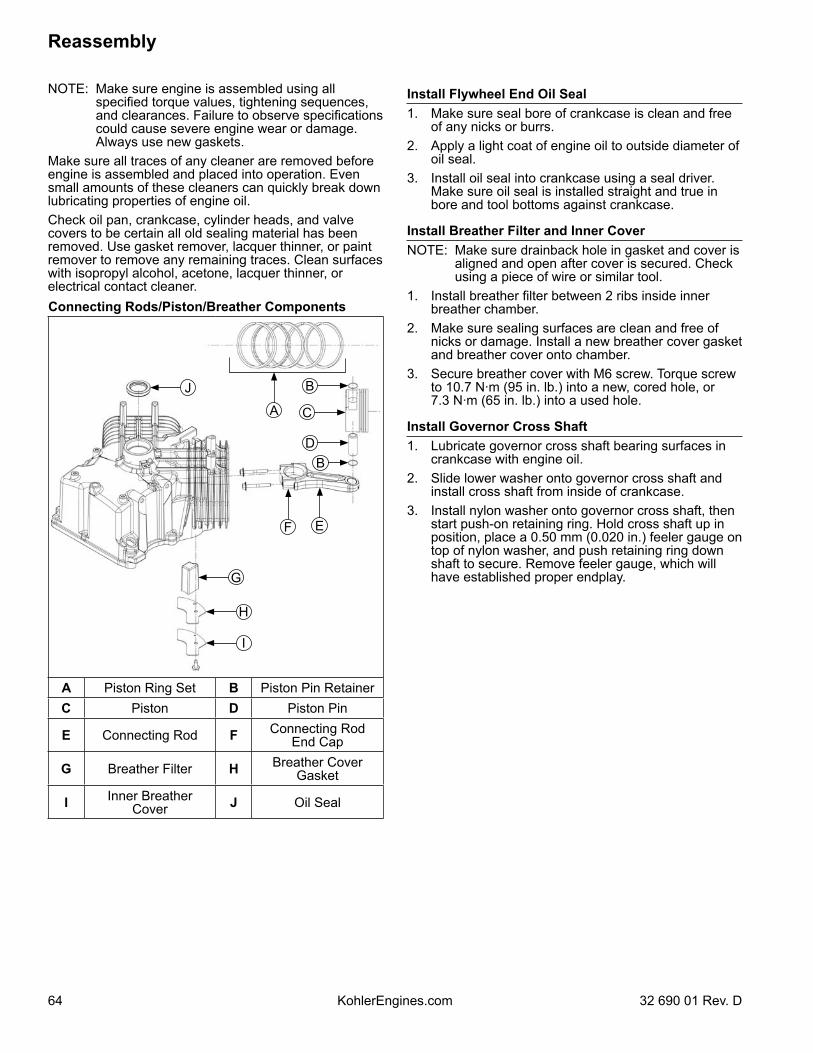
64
Reassembly
KohlerEngines.com 32 690 01 Rev. D
NOTE: Make sure engine is assembled using all specified torque values, tightening sequences, and clearances. Failure to observe specifications could cause severe engine wear or damage. Always use new gaskets.
Make sure all traces of any cleaner are removed before engine is assembled and placed into operation. Even small amounts of these cleaners can quickly break down lubricating properties of engine oil.Check oil pan, crankcase, cylinder heads, and valve covers to be certain all old sealing material has been removed. Use gasket remover, lacquer thinner, or paint remover to remove any remaining traces. Clean surfaces with isopropyl alcohol, acetone, lacquer thinner, or electrical contact cleaner.Connecting Rods/Piston/Breather Components
H
G
J
F
A
B
D
C
B
E
I
A Piston Ring Set B Piston Pin RetainerC Piston D Piston Pin
E Connecting Rod F Connecting RodEnd Cap
G Breather Filter H Breather CoverGasket
I Inner BreatherCover J Oil Seal
Install Flywheel End Oil Seal1. Make sure seal bore of crankcase is clean and free
of any nicks or burrs.2. Apply a light coat of engine oil to outside diameter of
oil seal.3. Install oil seal into crankcase using a seal driver.
Make sure oil seal is installed straight and true in bore and tool bottoms against crankcase.
Install Breather Filter and Inner CoverNOTE: Make sure drainback hole in gasket and cover is
aligned and open after cover is secured. Check using a piece of wire or similar tool.
1. Install breather filter between 2 ribs inside inner breather chamber.
2. Make sure sealing surfaces are clean and free of nicks or damage. Install a new breather cover gasket and breather cover onto chamber.
3. Secure breather cover with M6 screw. Torque screw to 10.7 N·m (95 in. lb.) into a new, cored hole, or 7.3 N·m (65 in. lb.) into a used hole.
Install Governor Cross Shaft1. Lubricate governor cross shaft bearing surfaces in
crankcase with engine oil. 2. Slide lower washer onto governor cross shaft and
install cross shaft from inside of crankcase.3. Install nylon washer onto governor cross shaft, then
start push-on retaining ring. Hold cross shaft up in position, place a 0.50 mm (0.020 in.) feeler gauge on top of nylon washer, and push retaining ring down shaft to secure. Remove feeler gauge, which will have established proper endplay.
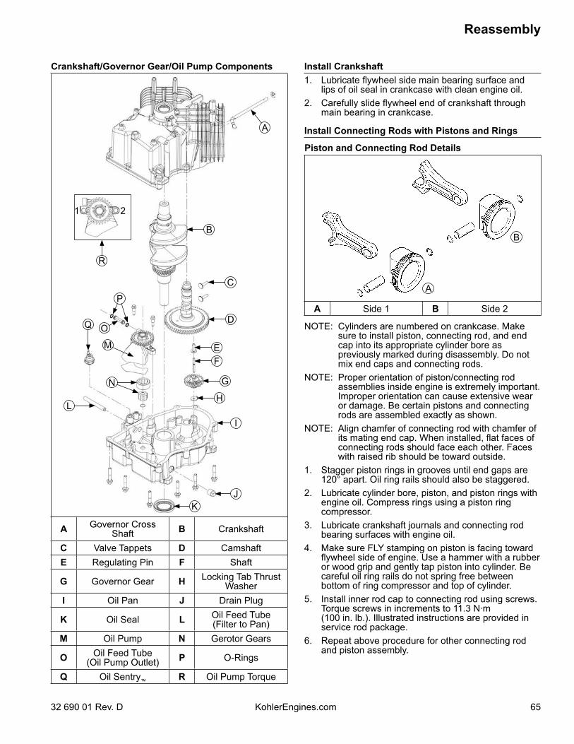
65
Reassembly
32 690 01 Rev. D KohlerEngines.com
Install Crankshaft1. Lubricate flywheel side main bearing surface and
lips of oil seal in crankcase with clean engine oil. 2. Carefully slide flywheel end of crankshaft through
main bearing in crankcase.
Install Connecting Rods with Pistons and Rings
Piston and Connecting Rod Details
A
B
A Side 1 B Side 2
NOTE: Cylinders are numbered on crankcase. Make sure to install piston, connecting rod, and end cap into its appropriate cylinder bore as previously marked during disassembly. Do not mix end caps and connecting rods.
NOTE: Proper orientation of piston/connecting rod assemblies inside engine is extremely important. Improper orientation can cause extensive wear or damage. Be certain pistons and connecting rods are assembled exactly as shown.
NOTE: Align chamfer of connecting rod with chamfer of its mating end cap. When installed, flat faces of connecting rods should face each other. Faces with raised rib should be toward outside.
1. Stagger piston rings in grooves until end gaps are 120° apart. Oil ring rails should also be staggered.
2. Lubricate cylinder bore, piston, and piston rings with engine oil. Compress rings using a piston ring compressor.
3. Lubricate crankshaft journals and connecting rod bearing surfaces with engine oil.
4. Make sure FLY stamping on piston is facing toward flywheel side of engine. Use a hammer with a rubber or wood grip and gently tap piston into cylinder. Be careful oil ring rails do not spring free between bottom of ring compressor and top of cylinder.
5. Install inner rod cap to connecting rod using screws. Torque screws in increments to 11.3 N·m (100 in. lb.). Illustrated instructions are provided in service rod package.
6. Repeat above procedure for other connecting rod and piston assembly.
Crankshaft/Governor Gear/Oil Pump Components
KJ
L
OQ
P
R
G
H
I
D
C
B
A
EF
N
M
1 2
A Governor Cross Shaft B Crankshaft
C Valve Tappets D CamshaftE Regulating Pin F Shaft
G Governor Gear H Locking Tab Thrust Washer
I Oil Pan J Drain Plug
K Oil Seal L Oil Feed Tube(Filter to Pan)
M Oil Pump N Gerotor Gears
O Oil Feed Tube(Oil Pump Outlet) P O-Rings
Q Oil Sentry™ R Oil Pump Torque
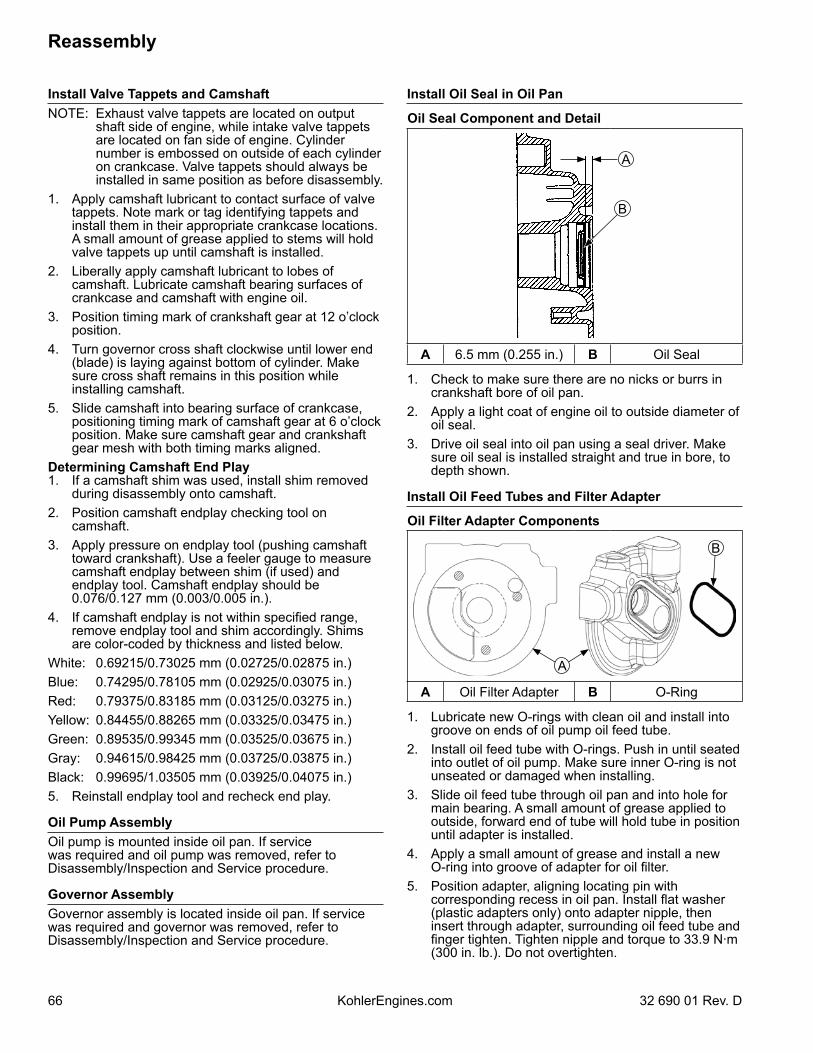
66
Reassembly
KohlerEngines.com 32 690 01 Rev. D
Install Valve Tappets and CamshaftNOTE: Exhaust valve tappets are located on output
shaft side of engine, while intake valve tappets are located on fan side of engine. Cylinder number is embossed on outside of each cylinder on crankcase. Valve tappets should always be installed in same position as before disassembly.
1. Apply camshaft lubricant to contact surface of valve tappets. Note mark or tag identifying tappets and install them in their appropriate crankcase locations. A small amount of grease applied to stems will hold valve tappets up until camshaft is installed.
2. Liberally apply camshaft lubricant to lobes of camshaft. Lubricate camshaft bearing surfaces of crankcase and camshaft with engine oil.
3. Position timing mark of crankshaft gear at 12 o’clock position.
4. Turn governor cross shaft clockwise until lower end (blade) is laying against bottom of cylinder. Make sure cross shaft remains in this position while installing camshaft.
5. Slide camshaft into bearing surface of crankcase, positioning timing mark of camshaft gear at 6 o’clock position. Make sure camshaft gear and crankshaft gear mesh with both timing marks aligned.
Determining Camshaft End Play1. If a camshaft shim was used, install shim removed
during disassembly onto camshaft.2. Position camshaft endplay checking tool on
camshaft.3. Apply pressure on endplay tool (pushing camshaft
toward crankshaft). Use a feeler gauge to measure camshaft endplay between shim (if used) and endplay tool. Camshaft endplay should be 0.076/0.127 mm (0.003/0.005 in.).
4. If camshaft endplay is not within specified range, remove endplay tool and shim accordingly. Shims are color-coded by thickness and listed below.
White: 0.69215/0.73025 mm (0.02725/0.02875 in.)Blue: 0.74295/0.78105 mm (0.02925/0.03075 in.)Red: 0.79375/0.83185 mm (0.03125/0.03275 in.)Yellow: 0.84455/0.88265 mm (0.03325/0.03475 in.)Green: 0.89535/0.99345 mm (0.03525/0.03675 in.)Gray: 0.94615/0.98425 mm (0.03725/0.03875 in.)Black: 0.99695/1.03505 mm (0.03925/0.04075 in.)5. Reinstall endplay tool and recheck end play.
Oil Pump AssemblyOil pump is mounted inside oil pan. If service was required and oil pump was removed, refer to Disassembly/Inspection and Service procedure.
Governor AssemblyGovernor assembly is located inside oil pan. If service was required and governor was removed, refer to Disassembly/Inspection and Service procedure.
Install Oil Seal in Oil Pan
Oil Seal Component and Detail
A
B
A 6.5 mm (0.255 in.) B Oil Seal
1. Check to make sure there are no nicks or burrs in crankshaft bore of oil pan.
2. Apply a light coat of engine oil to outside diameter of oil seal.
3. Drive oil seal into oil pan using a seal driver. Make sure oil seal is installed straight and true in bore, to depth shown.
Install Oil Feed Tubes and Filter Adapter
Oil Filter Adapter Components
A
B
A Oil Filter Adapter B O-Ring
1. Lubricate new O-rings with clean oil and install into groove on ends of oil pump oil feed tube.
2. Install oil feed tube with O-rings. Push in until seated into outlet of oil pump. Make sure inner O-ring is not unseated or damaged when installing.
3. Slide oil feed tube through oil pan and into hole for main bearing. A small amount of grease applied to outside, forward end of tube will hold tube in position until adapter is installed.
4. Apply a small amount of grease and install a new O-ring into groove of adapter for oil filter.
5. Position adapter, aligning locating pin with corresponding recess in oil pan. Install flat washer (plastic adapters only) onto adapter nipple, then insert through adapter, surrounding oil feed tube and finger tighten. Tighten nipple and torque to 33.9 N·m (300 in. lb.). Do not overtighten.
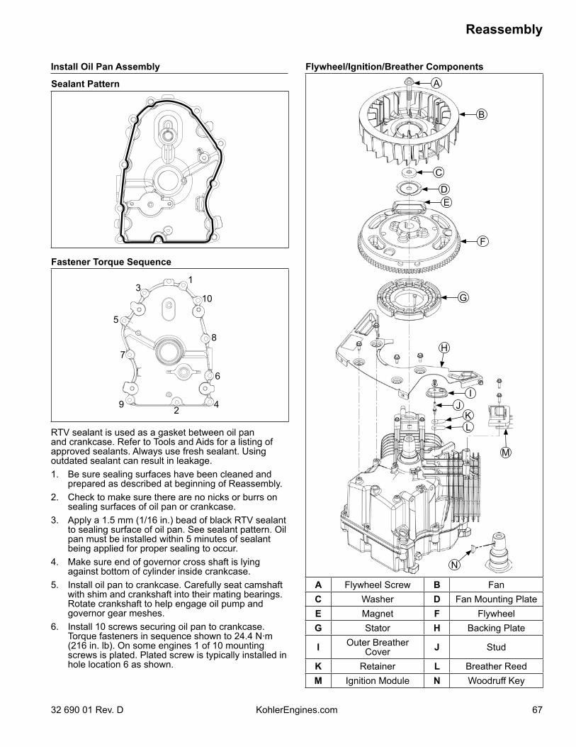
67
Reassembly
32 690 01 Rev. D KohlerEngines.com
Install Oil Pan Assembly
Sealant Pattern
Fastener Torque Sequence
1
10
8
6
429
7
5
3
RTV sealant is used as a gasket between oil pan and crankcase. Refer to Tools and Aids for a listing of approved sealants. Always use fresh sealant. Using outdated sealant can result in leakage.1. Be sure sealing surfaces have been cleaned and
prepared as described at beginning of Reassembly.2. Check to make sure there are no nicks or burrs on
sealing surfaces of oil pan or crankcase.3. Apply a 1.5 mm (1/16 in.) bead of black RTV sealant
to sealing surface of oil pan. See sealant pattern. Oil pan must be installed within 5 minutes of sealant being applied for proper sealing to occur.
4. Make sure end of governor cross shaft is lying against bottom of cylinder inside crankcase.
5. Install oil pan to crankcase. Carefully seat camshaft with shim and crankshaft into their mating bearings. Rotate crankshaft to help engage oil pump and governor gear meshes.
6. Install 10 screws securing oil pan to crankcase. Torque fasteners in sequence shown to 24.4 N·m (216 in. lb). On some engines 1 of 10 mounting screws is plated. Plated screw is typically installed in hole location 6 as shown.
Flywheel/Ignition/Breather Components
I
KL
J
M
F
G
H
C
B
A
DE
N
A Flywheel Screw B FanC Washer D Fan Mounting PlateE Magnet F FlywheelG Stator H Backing Plate
I Outer BreatherCover J Stud
K Retainer L Breather ReedM Ignition Module N Woodruff Key
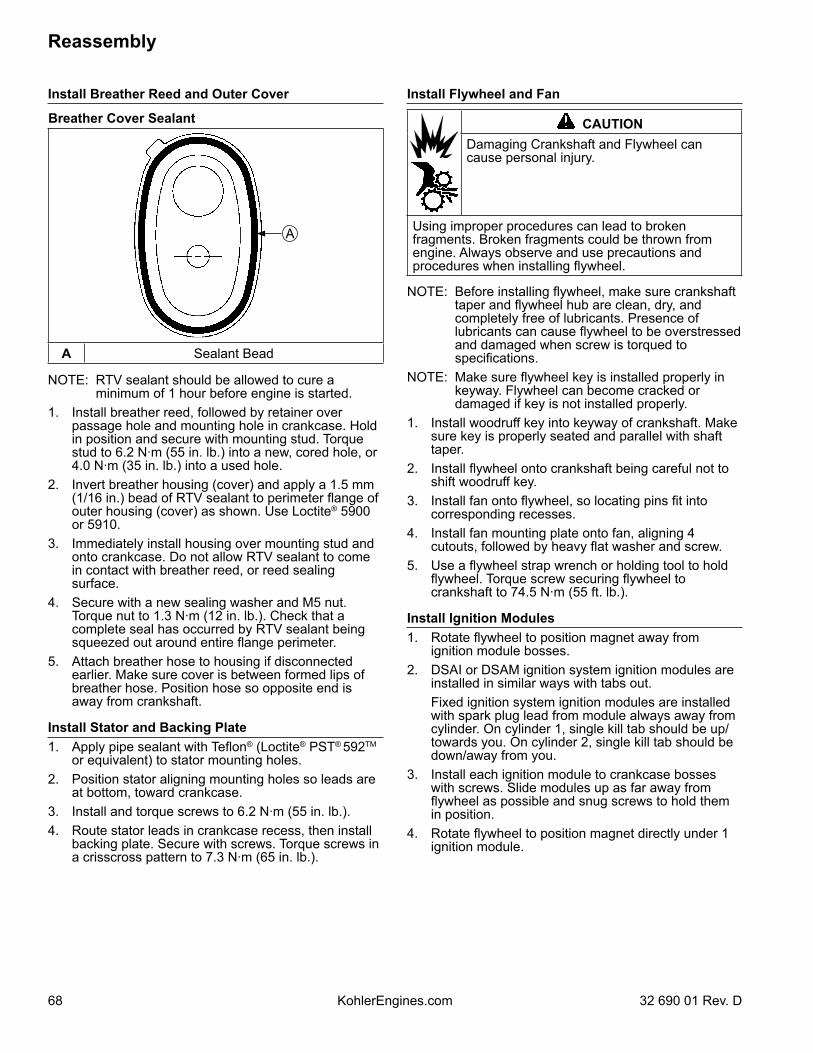
68
Reassembly
KohlerEngines.com 32 690 01 Rev. D
Install Flywheel and Fan
CAUTIONDamaging Crankshaft and Flywheel can cause personal injury.
Using improper procedures can lead to broken fragments. Broken fragments could be thrown from engine. Always observe and use precautions and procedures when installing flywheel.
NOTE: Before installing flywheel, make sure crankshaft taper and flywheel hub are clean, dry, and completely free of lubricants. Presence of lubricants can cause flywheel to be overstressed and damaged when screw is torqued to specifications.
NOTE: Make sure flywheel key is installed properly in keyway. Flywheel can become cracked or damaged if key is not installed properly.
1. Install woodruff key into keyway of crankshaft. Make sure key is properly seated and parallel with shaft taper.
2. Install flywheel onto crankshaft being careful not to shift woodruff key.
3. Install fan onto flywheel, so locating pins fit into corresponding recesses.
4. Install fan mounting plate onto fan, aligning 4 cutouts, followed by heavy flat washer and screw.
5. Use a flywheel strap wrench or holding tool to hold flywheel. Torque screw securing flywheel to crankshaft to 74.5 N·m (55 ft. lb.).
Install Ignition Modules1. Rotate flywheel to position magnet away from
ignition module bosses.2. DSAI or DSAM ignition system ignition modules are
installed in similar ways with tabs out. Fixed ignition system ignition modules are installed
with spark plug lead from module always away from cylinder. On cylinder 1, single kill tab should be up/towards you. On cylinder 2, single kill tab should be down/away from you.
3. Install each ignition module to crankcase bosses with screws. Slide modules up as far away from flywheel as possible and snug screws to hold them in position.
4. Rotate flywheel to position magnet directly under 1 ignition module.
Install Breather Reed and Outer Cover
Breather Cover Sealant
A
A Sealant Bead
NOTE: RTV sealant should be allowed to cure a minimum of 1 hour before engine is started.
1. Install breather reed, followed by retainer over passage hole and mounting hole in crankcase. Hold in position and secure with mounting stud. Torque stud to 6.2 N·m (55 in. lb.) into a new, cored hole, or 4.0 N·m (35 in. lb.) into a used hole.
2. Invert breather housing (cover) and apply a 1.5 mm (1/16 in.) bead of RTV sealant to perimeter flange of outer housing (cover) as shown. Use Loctite® 5900 or 5910.
3. Immediately install housing over mounting stud and onto crankcase. Do not allow RTV sealant to come in contact with breather reed, or reed sealing surface.
4. Secure with a new sealing washer and M5 nut. Torque nut to 1.3 N·m (12 in. lb.). Check that a complete seal has occurred by RTV sealant being squeezed out around entire flange perimeter.
5. Attach breather hose to housing if disconnected earlier. Make sure cover is between formed lips of breather hose. Position hose so opposite end is away from crankshaft.
Install Stator and Backing Plate1. Apply pipe sealant with Teflon® (Loctite® PST® 592TM
or equivalent) to stator mounting holes.2. Position stator aligning mounting holes so leads are
at bottom, toward crankcase.3. Install and torque screws to 6.2 N·m (55 in. lb.).4. Route stator leads in crankcase recess, then install
backing plate. Secure with screws. Torque screws in a crisscross pattern to 7.3 N·m (65 in. lb.).
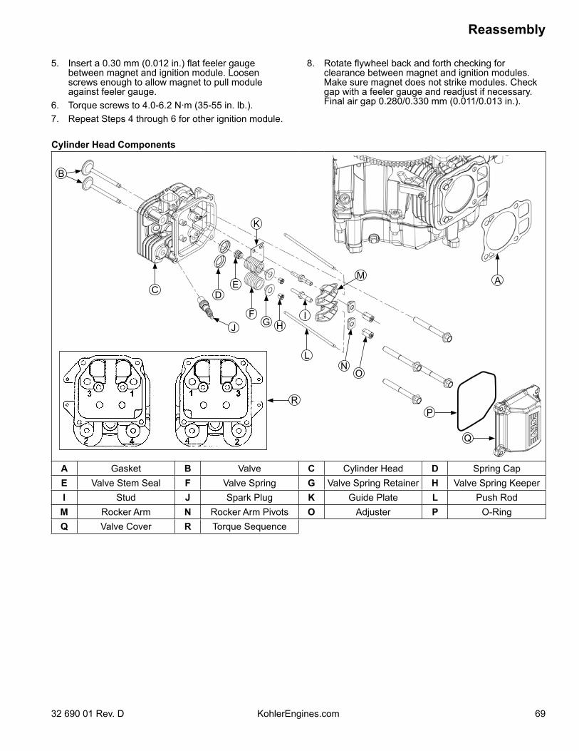
69
Reassembly
32 690 01 Rev. D KohlerEngines.com
Cylinder Head Components
A
B
DC
J
E
FH
IG
L
M
NO
K
P
Q
R
A Gasket B Valve C Cylinder Head D Spring CapE Valve Stem Seal F Valve Spring G Valve Spring Retainer H Valve Spring KeeperI Stud J Spark Plug K Guide Plate L Push Rod
M Rocker Arm N Rocker Arm Pivots O Adjuster P O-RingQ Valve Cover R Torque Sequence
5. Insert a 0.30 mm (0.012 in.) flat feeler gauge between magnet and ignition module. Loosen screws enough to allow magnet to pull module against feeler gauge.
6. Torque screws to 4.0-6.2 N·m (35-55 in. lb.).7. Repeat Steps 4 through 6 for other ignition module.
8. Rotate flywheel back and forth checking for clearance between magnet and ignition modules. Make sure magnet does not strike modules. Check gap with a feeler gauge and readjust if necessary. Final air gap 0.280/0.330 mm (0.011/0.013 in.).
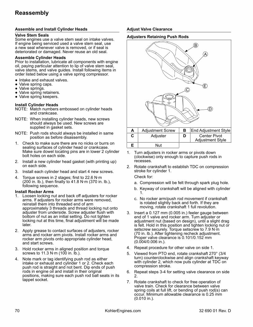
70
Reassembly
KohlerEngines.com 32 690 01 Rev. D
Adjust Valve Clearance
Adjusters Retaining Push Rods
A
D
CE
B
A Adjustment Screw B End Adjustment StyleC Adjuster D Center Pivot
Adjustment StyleE Nut
1. Turn adjusters in rocker arms or pivots down (clockwise) only enough to capture push rods in recesses.
2. Rotate crankshaft to establish TDC on compression stroke for cylinder 1.
Check for: a. Compression will be felt through spark plug hole. b. Keyway of crankshaft will be aligned with cylinder
1. c. No rocker arm/push rod movement if crankshaft
is rotated slightly back and forth. If they are moving, rotate crankshaft 1 full revolution.
3. Insert a 0.127 mm (0.005 in.) feeler gauge between end of 1 valve and rocker arm. Turn adjuster or adjustment nut (based on design), until a slight drag is felt. Hold in this position and tighten locking nut or setscrew securely. Torque setscrew to 7.9 N·m (70 in. lb.). After tightening recheck adjustment. Proper valve clearance is 0.101/0.152 mm (0.004/0.006 in.).
4. Repeat procedure for other valve on side 1.5. Viewed from PTO end, rotate crankshaft 270° (3/4
turn) counterclockwise and align crankshaft keyway with cylinder 2, which now puts cylinder at TDC on compression stroke.
6. Repeat steps 3-4 for setting valve clearance on side 2.
7. Rotate crankshaft to check for free operation of valve train. Check for clearance between valve spring coils at full lift, or bending of push rod(s) can occur. Minimum allowable clearance is 0.25 mm (0.010 in.).
Assemble and Install Cylinder HeadsValve Stem SealsSome engines use a valve stem seal on intake valves. If engine being serviced used a valve stem seal, use a new seal whenever valve is removed, or if seal is deteriorated or damaged. Never reuse an old seal.Assemble Cylinder HeadsPrior to installation, lubricate all components with engine oil, paying particular attention to lip of valve stem seal, valve stems, and valve guides. Install following items in order listed below using a valve spring compressor.● Intake and exhaust valves.● Valve spring caps.● Valve springs.● Valve spring retainers.● Valve spring keepers.
Install Cylinder HeadsNOTE: Match numbers embossed on cylinder heads
and crankcase.NOTE: When installing cylinder heads, new screws
should always be used. New screws are supplied in gasket sets.
NOTE: Push rods should always be installed in same position as before disassembly.
1. Check to make sure there are no nicks or burrs on sealing surfaces of cylinder head or crankcase. Make sure dowel locating pins are in lower 2 cylinder bolt holes on each side.
2. Install a new cylinder head gasket (with printing up) on each side.
3. Install each cylinder head and start 4 new screws.4. Torque screws in 2 stages; first to 22.6 N·m
(200 in. lb.), then finally to 41.8 N·m (370 in. lb.), following sequence.
Install Rocker Arms1. Loosen locking nut and back off adjusters for rocker
arms. If adjusters for rocker arms were removed, reinstall them into threaded end of arm approximately 3 threads and thread locking nut onto adjuster from underside. Screw adjuster flush with bottom of nut as an initial setting. Do not tighten locking nut at this time, final adjustment will be made later.
2. Apply grease to contact surfaces of adjusters, rocker arms and rocker arm pivots. Install rocker arms and rocker arm pivots onto appropriate cylinder head, and start screws.
3. Hold rocker arms in aligned position and torque screws to 11.3 N·m (100 in. lb.).
4. Note mark or tag identifying push rod as either intake or exhaust and cylinder 1 or 2. Check each push rod is straight and not bent. Dip ends of push rods in engine oil and install in their original positions, making sure each push rod ball seats in its tappet socket.
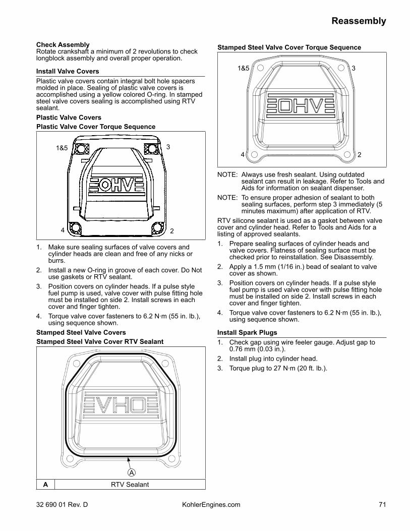
71
Reassembly
32 690 01 Rev. D KohlerEngines.com
Check AssemblyRotate crankshaft a minimum of 2 revolutions to check longblock assembly and overall proper operation.
Install Valve CoversPlastic valve covers contain integral bolt hole spacers molded in place. Sealing of plastic valve covers is accomplished using a yellow colored O-ring. In stamped steel valve covers sealing is accomplished using RTV sealant.Plastic Valve CoversPlastic Valve Cover Torque Sequence
1&5 3
24
1. Make sure sealing surfaces of valve covers and cylinder heads are clean and free of any nicks or burrs.
2. Install a new O-ring in groove of each cover. Do Not use gaskets or RTV sealant.
3. Position covers on cylinder heads. If a pulse style fuel pump is used, valve cover with pulse fitting hole must be installed on side 2. Install screws in each cover and finger tighten.
4. Torque valve cover fasteners to 6.2 N·m (55 in. lb.), using sequence shown.
Stamped Steel Valve CoversStamped Steel Valve Cover RTV Sealant
A
A RTV Sealant
Stamped Steel Valve Cover Torque Sequence
1&5 3
24
NOTE: Always use fresh sealant. Using outdated sealant can result in leakage. Refer to Tools and Aids for information on sealant dispenser.
NOTE: To ensure proper adhesion of sealant to both sealing surfaces, perform step 3 immediately (5 minutes maximum) after application of RTV.
RTV silicone sealant is used as a gasket between valve cover and cylinder head. Refer to Tools and Aids for a listing of approved sealants.1. Prepare sealing surfaces of cylinder heads and
valve covers. Flatness of sealing surface must be checked prior to reinstallation. See Disassembly.
2. Apply a 1.5 mm (1/16 in.) bead of sealant to valve cover as shown.
3. Position covers on cylinder heads. If a pulse style fuel pump is used valve cover with pulse fitting hole must be installed on side 2. Install screws in each cover and finger tighten.
4. Torque valve cover fasteners to 6.2 N·m (55 in. lb.), using sequence shown.
Install Spark Plugs1. Check gap using wire feeler gauge. Adjust gap to
0.76 mm (0.03 in.).2. Install plug into cylinder head.3. Torque plug to 27 N·m (20 ft. lb.).
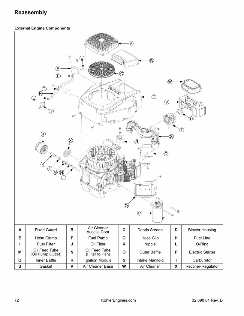
72
Reassembly
KohlerEngines.com 32 690 01 Rev. D
External Engine Components
JX
E
P
G
W
V
E
E
F
H
K
I
LM N
L
O
B
A
C
D
R
Q
ST
U
A Fixed Guard B Air Cleaner Access Door C Debris Screen D Blower Housing
E Hose Clamp F Fuel Pump G Hose Clip H Fuel LineI Fuel Filter J Oil Filter K Nipple L O-Ring
M Oil Feed Tube(Oil Pump Outlet) N Oil Feed Tube
(Filter to Pan) O Outer Baffle P Electric Starter
Q Inner Baffle R Ignition Module S Intake Manifold T CarburetorU Gasket V Air Cleaner Base W Air Cleaner X Rectifier-Regulator
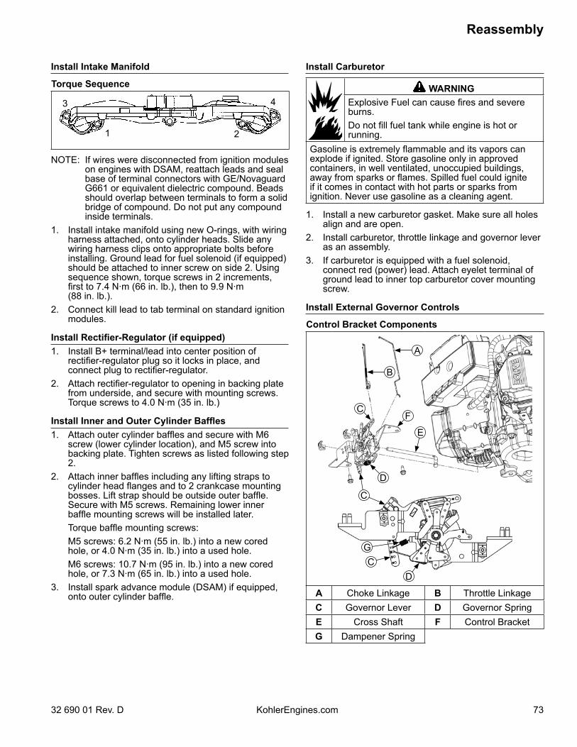
73
Reassembly
32 690 01 Rev. D KohlerEngines.com
Install Intake Manifold
Torque Sequence
1 2
3 4
NOTE: If wires were disconnected from ignition modules on engines with DSAM, reattach leads and seal base of terminal connectors with GE/Novaguard G661 or equivalent dielectric compound. Beads should overlap between terminals to form a solid bridge of compound. Do not put any compound inside terminals.
1. Install intake manifold using new O-rings, with wiring harness attached, onto cylinder heads. Slide any wiring harness clips onto appropriate bolts before installing. Ground lead for fuel solenoid (if equipped) should be attached to inner screw on side 2. Using sequence shown, torque screws in 2 increments, first to 7.4 N·m (66 in. lb.), then to 9.9 N·m (88 in. lb.).
2. Connect kill lead to tab terminal on standard ignition modules.
Install Rectifier-Regulator (if equipped)1. Install B+ terminal/lead into center position of
rectifier-regulator plug so it locks in place, and connect plug to rectifier-regulator.
2. Attach rectifier-regulator to opening in backing plate from underside, and secure with mounting screws. Torque screws to 4.0 N·m (35 in. lb.)
Install Inner and Outer Cylinder Baffles1. Attach outer cylinder baffles and secure with M6
screw (lower cylinder location), and M5 screw into backing plate. Tighten screws as listed following step 2.
2. Attach inner baffles including any lifting straps to cylinder head flanges and to 2 crankcase mounting bosses. Lift strap should be outside outer baffle. Secure with M5 screws. Remaining lower inner baffle mounting screws will be installed later.
Torque baffle mounting screws: M5 screws: 6.2 N·m (55 in. lb.) into a new cored
hole, or 4.0 N·m (35 in. lb.) into a used hole. M6 screws: 10.7 N·m (95 in. lb.) into a new cored
hole, or 7.3 N·m (65 in. lb.) into a used hole.3. Install spark advance module (DSAM) if equipped,
onto outer cylinder baffle.
Install Carburetor
WARNINGExplosive Fuel can cause fires and severe burns.Do not fill fuel tank while engine is hot or running.
Gasoline is extremely flammable and its vapors can explode if ignited. Store gasoline only in approved containers, in well ventilated, unoccupied buildings, away from sparks or flames. Spilled fuel could ignite if it comes in contact with hot parts or sparks from ignition. Never use gasoline as a cleaning agent.
1. Install a new carburetor gasket. Make sure all holes align and are open.
2. Install carburetor, throttle linkage and governor lever as an assembly.
3. If carburetor is equipped with a fuel solenoid, connect red (power) lead. Attach eyelet terminal of ground lead to inner top carburetor cover mounting screw.
Install External Governor Controls
Control Bracket Components
F
G
C
C
C
B
A
D
D
E
A Choke Linkage B Throttle LinkageC Governor Lever D Governor SpringE Cross Shaft F Control BracketG Dampener Spring
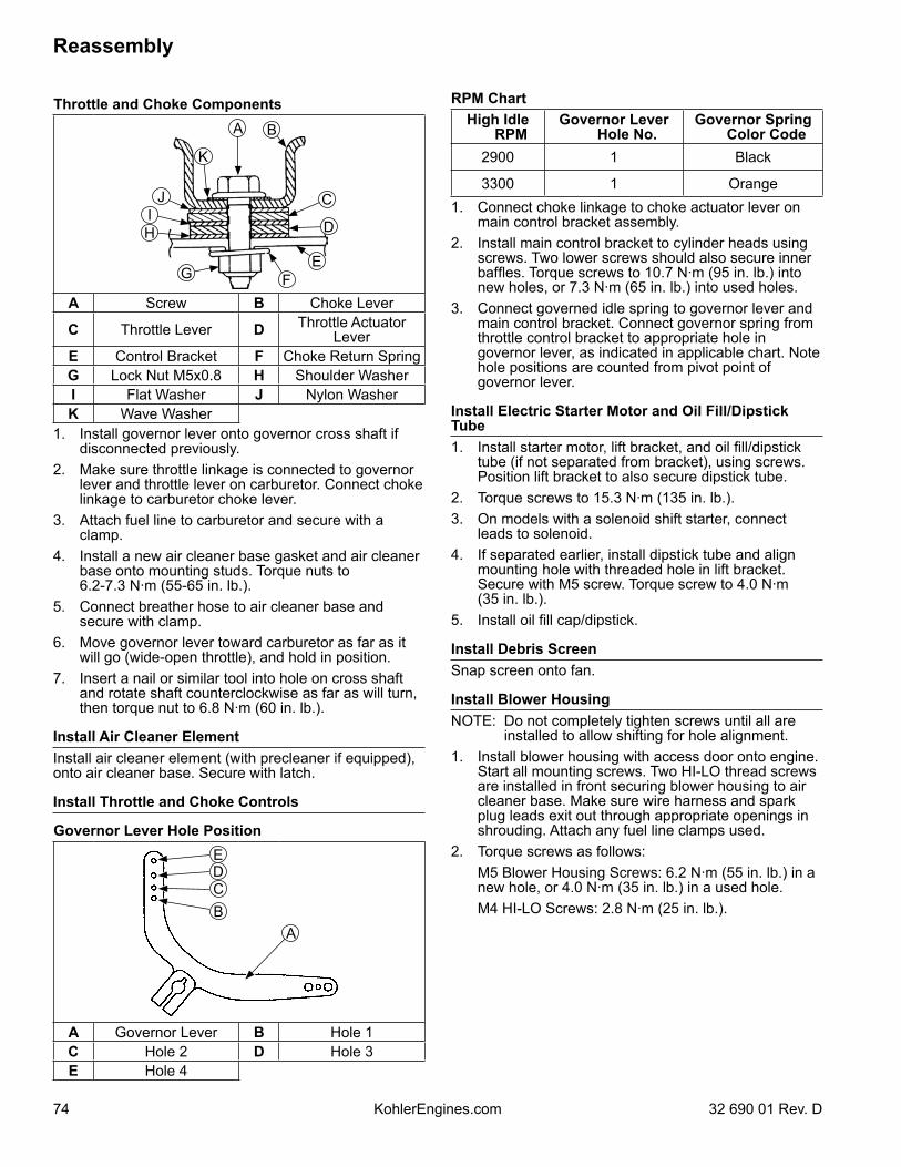
74
Reassembly
KohlerEngines.com 32 690 01 Rev. D
Throttle and Choke ComponentsA
K
B
D
EFG
CI
J
H
A Screw B Choke Lever
C Throttle Lever D Throttle Actuator Lever
E Control Bracket F Choke Return SpringG Lock Nut M5x0.8 H Shoulder WasherI Flat Washer J Nylon WasherK Wave Washer
1. Install governor lever onto governor cross shaft if disconnected previously.
2. Make sure throttle linkage is connected to governor lever and throttle lever on carburetor. Connect choke linkage to carburetor choke lever.
3. Attach fuel line to carburetor and secure with a clamp.
4. Install a new air cleaner base gasket and air cleaner base onto mounting studs. Torque nuts to 6.2-7.3 N·m (55-65 in. lb.).
5. Connect breather hose to air cleaner base and secure with clamp.
6. Move governor lever toward carburetor as far as it will go (wide-open throttle), and hold in position.
7. Insert a nail or similar tool into hole on cross shaft and rotate shaft counterclockwise as far as will turn, then torque nut to 6.8 N·m (60 in. lb.).
Install Air Cleaner ElementInstall air cleaner element (with precleaner if equipped), onto air cleaner base. Secure with latch.
Install Throttle and Choke Controls
Governor Lever Hole Position
A
EDCB
A Governor Lever B Hole 1C Hole 2 D Hole 3E Hole 4
RPM ChartHigh Idle
RPMGovernor Lever
Hole No.Governor Spring
Color Code2900 1 Black
3300 1 Orange1. Connect choke linkage to choke actuator lever on
main control bracket assembly.2. Install main control bracket to cylinder heads using
screws. Two lower screws should also secure inner baffles. Torque screws to 10.7 N·m (95 in. lb.) into new holes, or 7.3 N·m (65 in. lb.) into used holes.
3. Connect governed idle spring to governor lever and main control bracket. Connect governor spring from throttle control bracket to appropriate hole in governor lever, as indicated in applicable chart. Note hole positions are counted from pivot point of governor lever.
Install Electric Starter Motor and Oil Fill/Dipstick Tube1. Install starter motor, lift bracket, and oil fill/dipstick
tube (if not separated from bracket), using screws. Position lift bracket to also secure dipstick tube.
2. Torque screws to 15.3 N·m (135 in. lb.).3. On models with a solenoid shift starter, connect
leads to solenoid. 4. If separated earlier, install dipstick tube and align
mounting hole with threaded hole in lift bracket. Secure with M5 screw. Torque screw to 4.0 N·m (35 in. lb.).
5. Install oil fill cap/dipstick.
Install Debris ScreenSnap screen onto fan.
Install Blower HousingNOTE: Do not completely tighten screws until all are
installed to allow shifting for hole alignment.1. Install blower housing with access door onto engine.
Start all mounting screws. Two HI-LO thread screws are installed in front securing blower housing to air cleaner base. Make sure wire harness and spark plug leads exit out through appropriate openings in shrouding. Attach any fuel line clamps used.
2. Torque screws as follows: M5 Blower Housing Screws: 6.2 N·m (55 in. lb.) in a
new hole, or 4.0 N·m (35 in. lb.) in a used hole. M4 HI-LO Screws: 2.8 N·m (25 in. lb.).
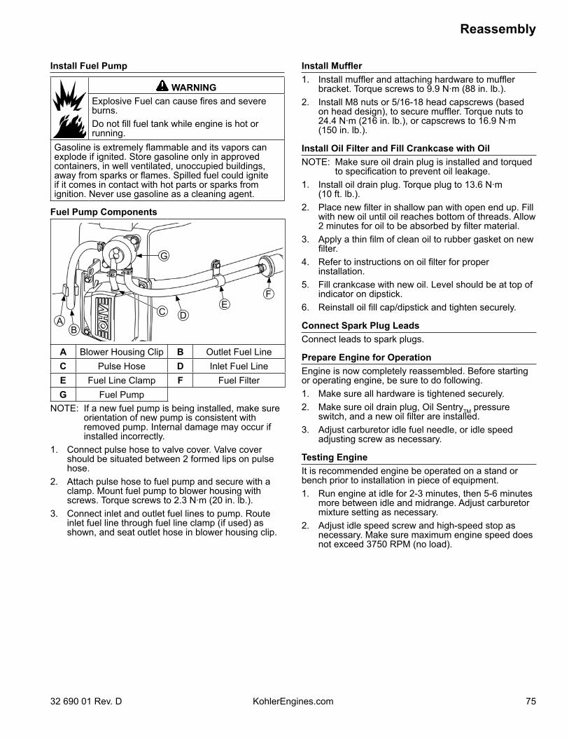
75
Reassembly
32 690 01 Rev. D KohlerEngines.com
Install Fuel Pump
WARNINGExplosive Fuel can cause fires and severe burns.Do not fill fuel tank while engine is hot or running.
Gasoline is extremely flammable and its vapors can explode if ignited. Store gasoline only in approved containers, in well ventilated, unoccupied buildings, away from sparks or flames. Spilled fuel could ignite if it comes in contact with hot parts or sparks from ignition. Never use gasoline as a cleaning agent.
Fuel Pump Components
BA
G
C DE
F
A Blower Housing Clip B Outlet Fuel LineC Pulse Hose D Inlet Fuel LineE Fuel Line Clamp F Fuel FilterG Fuel Pump
NOTE: If a new fuel pump is being installed, make sure orientation of new pump is consistent with removed pump. Internal damage may occur if installed incorrectly.
1. Connect pulse hose to valve cover. Valve cover should be situated between 2 formed lips on pulse hose.
2. Attach pulse hose to fuel pump and secure with a clamp. Mount fuel pump to blower housing with screws. Torque screws to 2.3 N·m (20 in. lb.).
3. Connect inlet and outlet fuel lines to pump. Route inlet fuel line through fuel line clamp (if used) as shown, and seat outlet hose in blower housing clip.
Install Muffler1. Install muffler and attaching hardware to muffler
bracket. Torque screws to 9.9 N·m (88 in. lb.).2. Install M8 nuts or 5/16-18 head capscrews (based
on head design), to secure muffler. Torque nuts to 24.4 N·m (216 in. lb.), or capscrews to 16.9 N·m (150 in. lb.).
Install Oil Filter and Fill Crankcase with OilNOTE: Make sure oil drain plug is installed and torqued
to specification to prevent oil leakage.1. Install oil drain plug. Torque plug to 13.6 N·m
(10 ft. lb.).2. Place new filter in shallow pan with open end up. Fill
with new oil until oil reaches bottom of threads. Allow 2 minutes for oil to be absorbed by filter material.
3. Apply a thin film of clean oil to rubber gasket on new filter.
4. Refer to instructions on oil filter for proper installation.
5. Fill crankcase with new oil. Level should be at top of indicator on dipstick.
6. Reinstall oil fill cap/dipstick and tighten securely.
Connect Spark Plug LeadsConnect leads to spark plugs.
Prepare Engine for OperationEngine is now completely reassembled. Before starting or operating engine, be sure to do following.1. Make sure all hardware is tightened securely.2. Make sure oil drain plug, Oil SentryTM pressure
switch, and a new oil filter are installed.3. Adjust carburetor idle fuel needle, or idle speed
adjusting screw as necessary.
Testing EngineIt is recommended engine be operated on a stand or bench prior to installation in piece of equipment.1. Run engine at idle for 2-3 minutes, then 5-6 minutes
more between idle and midrange. Adjust carburetor mixture setting as necessary.
2. Adjust idle speed screw and high-speed stop as necessary. Make sure maximum engine speed does not exceed 3750 RPM (no load).

76 KohlerEngines.com 32 690 01 Rev. D
© 2011 by Kohler Co. All rights reserved.