Embed Size (px)
DESCRIPTION
SV 510 Technical
Citation preview

7/17/2019 SV510 technical
http://slidepdf.com/reader/full/sv510-technical 1/87
Service and Operation for SV505/510How They Work
By Gerry PettyCell 770 712 6168
7/17/2019 SV510 technical
http://slidepdf.com/reader/full/sv510-technical 2/87
Types
T / Pad Foot DrumUsed primarily in clay, other cohesive soils

7/17/2019 SV510 technical
http://slidepdf.com/reader/full/sv510-technical 3/87
D / Smooth Drum
7/17/2019 SV510 technical
http://slidepdf.com/reader/full/sv510-technical 4/87
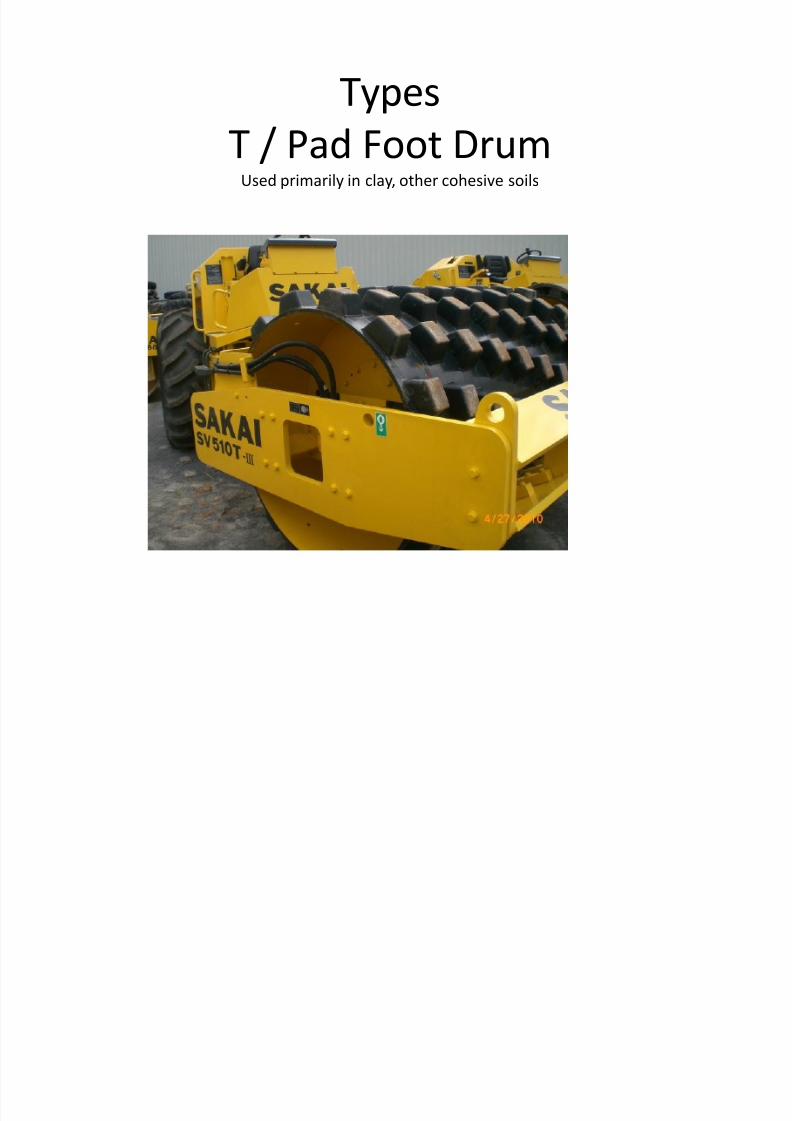
TF / Combo DrumA pad foot drum with a smooth 2 piece shell bolted on

7/17/2019 SV510 technical
http://slidepdf.com/reader/full/sv510-technical 5/87
TB/ Pad Foot with a Blade

7/17/2019 SV510 technical
http://slidepdf.com/reader/full/sv510-technical 6/87
ScrapersBelow, a double row of T drum scraper bars , this is the only way to run two sets of bars, if these
bars are installed behind the drum as they were in the past, dried packed dirt can break themounting brackets off. Normally only the upper set of bars are needed.

7/17/2019 SV510 technical
http://slidepdf.com/reader/full/sv510-technical 7/87
Only D models (smooth drum)should have scrapers mounted here, behind the drum.

7/17/2019 SV510 technical
http://slidepdf.com/reader/full/sv510-technical 8/87
Below, D drum scraper bars. It only looks like its touching, allow one half inchof clearance.
7/17/2019 SV510 technical
http://slidepdf.com/reader/full/sv510-technical 9/87
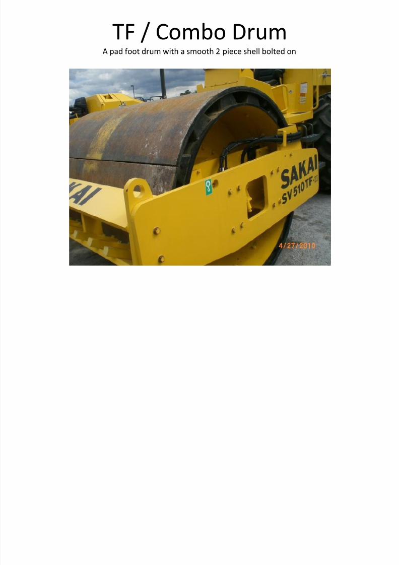
A TF drum (combo) comes with both styles of scraper bars. They can be stored on theroller as shown. Scrapers should be adjusted to within one half inch away from the
drum.

7/17/2019 SV510 technical
http://slidepdf.com/reader/full/sv510-technical 10/87
TF Drums
• Sakai Combo drums are a good way to gain more utilization from a singlemachine.
• Over 4000 pounds is added to the drum, this is good for compaction butreduces travel performance on slopes. The larger diameter reduces torqueto the ground and conversely increases speed.
• To install shell kit, clean / scrape all surfaces down to the paint. Themounting flange should make full contact with the drum. If the shellhalves only contact the drum at the shells 4 corners the corners must betrimmed. If the shell is resting on four tiny points (corners) it can’t bepried into bolt hole alignment.
• Use best hardware available, only heavy washers. Torque to 220 ft lbs.These can be a Bear to install. Don’t be afraid to trim holes if it’s OK withthe owner. I suggest only trimming the shell flange, not the drum.

7/17/2019 SV510 technical
http://slidepdf.com/reader/full/sv510-technical 11/87
General maintenance is simple. For details see the operator manual or theService Chart. Not mentioned in the chart but very important is keeping the
cooling system clean.

7/17/2019 SV510 technical
http://slidepdf.com/reader/full/sv510-technical 12/87
Access to the oil cooler, CAC and radiator is through the cover behind the seat. Allmachine functions are hydraulic so its important to keep the coolers clean to promotelong life. The trouble you will get from stopped up coolers is generally very expensiveand irreversible once it shows up. A single plastic grocery bag sucked over the cooler
can cause big problems, always check for obstructions by looking through the top
door.

7/17/2019 SV510 technical
http://slidepdf.com/reader/full/sv510-technical 13/87
The coolers/ radiator can be inspected from the top cover, behind the seat.Coolant over flow bottle is at the top of the picture.

7/17/2019 SV510 technical
http://slidepdf.com/reader/full/sv510-technical 14/87
If the maintenance dash light comes on, drain water from the separator petcock onthe bottom of the filter. Then bleed the connection at the main fuel filter. A good
practice would be to also drain the tank trap at the same time.

7/17/2019 SV510 technical
http://slidepdf.com/reader/full/sv510-technical 15/87
The fuel tank is all metal, keep rental machines full of fuel and drain the trash trapregularly. Older 505 & 510’s with tier 2 Cummins power and tier 1 Isuzu engines also
have screens at the fuel filter inlet banjo fittings. Older machines may also have inlinetrash screens above the fuel tank.
Trash in the fuel system is the number one cause of trouble from these machineswhen rented.

7/17/2019 SV510 technical
http://slidepdf.com/reader/full/sv510-technical 16/87
Air filters are two stage, we do not recommend blowing out air filters, there is greatopportunity to ruin the engine , never remove the inner filter unless there is a new
one to install.

7/17/2019 SV510 technical
http://slidepdf.com/reader/full/sv510-technical 17/87
There is no seal at the air filter inlet tube to the filter housing, the filters themselvesseal to the inside and outside circumference of the tube inside the housing, a loose fit
of this tube to the housing will not allow dirt into the system.

7/17/2019 SV510 technical
http://slidepdf.com/reader/full/sv510-technical 18/87
Check security of CAC hose clamps, they have been known to blow off. The machinewill be weak and noise made by the leak will be noticeable.

7/17/2019 SV510 technical
http://slidepdf.com/reader/full/sv510-technical 19/87
There are only 8 grease fittings, all around the articulation joint. Two are on theslewing ring, two on the trunion bearings and two on each steer cylinder

7/17/2019 SV510 technical
http://slidepdf.com/reader/full/sv510-technical 20/87
There are numerous decals on our machines indicating maintenance procedures, herethe vibe oil check method is demonstrated. There is a breather on the bearing housing
that vents the viberator housing. Misting, dampness around the breather is normal.

7/17/2019 SV510 technical
http://slidepdf.com/reader/full/sv510-technical 21/87
Drum drive on left side, one of the gearbox plugs is shown. The drive is a motorgearbox combination, the motor is internal. These front drives rarely give trouble and
cannot leak into the vibe cavity.
R d i i i D li it d li l t l If l ti i i th t i

7/17/2019 SV510 technical
http://slidepdf.com/reader/full/sv510-technical 22/87
Rear drive is via Dana limited slip planetary axle. If you ever see only one tire spinning, the non turningside axle is broken. Both wheels are always under power, when one tire needs to go faster the Limited SlipDifferential allows it. Loud popping or grinding noise during sharp turns is not normal. You may hear the
muffled “bumping” during a turn of the Diff lock slipping as the outside axle must go faster than theinside axle.To fully drain the axle the outboard planetary plugs need to be removed also. To refill place
the plug at 3 or 9 O-clock

7/17/2019 SV510 technical
http://slidepdf.com/reader/full/sv510-technical 23/87
Without the deck on, the axle oil level plugs are clearly visible, after draining, insureoil is filled up to plug level at the planetarys and the center housing.

7/17/2019 SV510 technical
http://slidepdf.com/reader/full/sv510-technical 24/87
Hydraulic tank has a sight gauge and there is a 50 micron suction screen inside thetank. It should be removed only in the case of a major failure. To remove the suction
screen the deck must be lifted or the tank lowered.

7/17/2019 SV510 technical
http://slidepdf.com/reader/full/sv510-technical 25/87
The hydraulic filters are below the deck on the left side, also notice the chargepressure test port and the brake hose both off of the rear filter. This is where the brake
solenoid valve receives pressure to release the brakes.
7/17/2019 SV510 technical
http://slidepdf.com/reader/full/sv510-technical 26/87
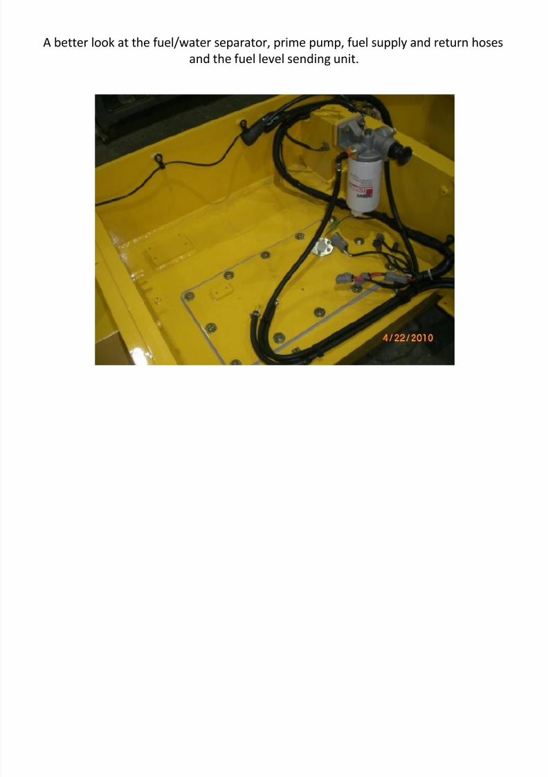
A better look at the fuel/water separator, prime pump, fuel supply and return hosesand the fuel level sending unit.

7/17/2019 SV510 technical
http://slidepdf.com/reader/full/sv510-technical 27/87
505 & 510 Tier three machines are 12 volt, before tier 3, both machines were 24 volt.

7/17/2019 SV510 technical
http://slidepdf.com/reader/full/sv510-technical 28/87
General operation• Operation, power train and vibration system is
the same for the 505 & 510 machine family, thedifference is intended use, drum type and tires.
• The SV505 and the SV510 differ mainly in atraction control system is added to the 510.
• Traction control system on 510 consist ofupgraded front drum drive, upgraded rear drive
motor and a computer that balances torque inthe two drives.
• Travel & vibe speeds can be changed at full RPM

7/17/2019 SV510 technical
http://slidepdf.com/reader/full/sv510-technical 29/87
Tier three 505 and 510’s use throttle switches instead of levers. Also shown here arethe engine trouble lights, Engine stop indicates a critical fault has occurred and theoperator should shut down as soon as it is safe. Warning indicates maintenance is
required, usually the water separator requires draining, wait to start light indicates thecomputers pre start check can’t be completed, look for loose connections.

7/17/2019 SV510 technical
http://slidepdf.com/reader/full/sv510-technical 30/87
Park brake button is push on, push offBe aware that pulling on the button like a truck air brake valve will cause obvious
mechanical failure.
7/17/2019 SV510 technical
http://slidepdf.com/reader/full/sv510-technical 31/87
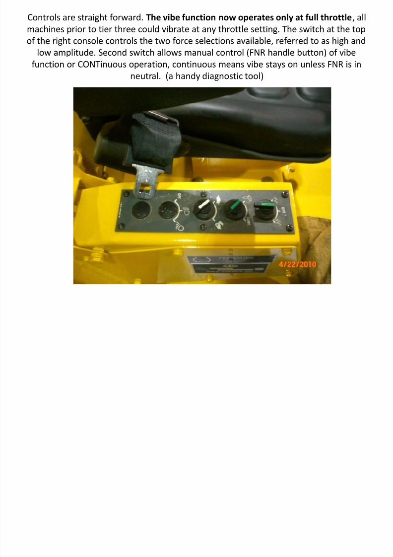
Controls are straight forward. The vibe function now operates only at full throttle , allmachines prior to tier three could vibrate at any throttle setting. The switch at the topof the right console controls the two force selections available, referred to as high and
low amplitude. Second switch allows manual control (FNR handle button) of vibefunction or CONTinuous operation, continuous means vibe stays on unless FNR is in
neutral. (a handy diagnostic tool)

7/17/2019 SV510 technical
http://slidepdf.com/reader/full/sv510-technical 32/87
The FNR lever grip houses a thumb switch to control vibe manually. A back up andneutral switch operate via movement of the FNR. The FNR is used to control travel
speed and stopping via dynamic braking. The machine will creep on a hill if onlydynamic braking is applied. Shutting off the machine or setting the park brake will
hold the machine securely. There is no brake in the front drum .

7/17/2019 SV510 technical
http://slidepdf.com/reader/full/sv510-technical 33/87
Hoods are hinged at the rear for access to engine & hydraulics. Always use the proprod, the hood is heavy and can cause injury if closed on someone.
Brake operation

7/17/2019 SV510 technical
http://slidepdf.com/reader/full/sv510-technical 34/87
Brake operationBrake operation is spring applied, pressure released. The brake valve is operated by either thepedal switch or the dash park on/off button. To apply the brake, charge pressure is diverted bythe brake valve to tank and spring force compresses the brakes. To release the brakes, charge
pressure is directed against pistons that overcome the spring force, releasing the brakes. Constantcharge pressure (about 340 psi) is required to keep the brakes released. The pedal switch is a
momentary type switch. Brakes are not proportioning. If you want to know brake condition, pullup on a slope, go to neutral and leave the engine at idle. The machine should creep down hill.
Now kill the engine, the springs will set the brakes and you should stop instantly.

7/17/2019 SV510 technical
http://slidepdf.com/reader/full/sv510-technical 35/87
Towing the machine may become necessary for various reasons To move a dead Sakai
7/17/2019 SV510 technical
http://slidepdf.com/reader/full/sv510-technical 36/87
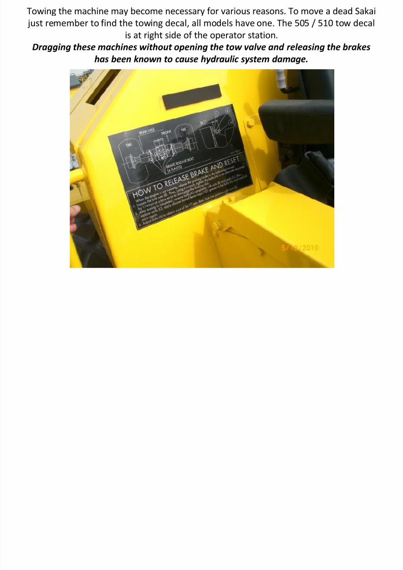
Towing the machine may become necessary for various reasons. To move a dead Sakai just remember to find the towing decal, all models have one. The 505 / 510 tow decal
is at right side of the operator station.Dragging these machines without opening the tow valve and releasing the brakes
has been known to cause hydraulic system damage.

7/17/2019 SV510 technical
http://slidepdf.com/reader/full/sv510-technical 37/87
There are 4 brake release screws on the axle, use carefully, the piston tangthat the screw pushes against can be broken off by too much torque on thescrews. The towing decal contains measurements to safely use the screws.

7/17/2019 SV510 technical
http://slidepdf.com/reader/full/sv510-technical 38/87
A tow valve is provided to prevent dynamic braking while under tow. The tow valve is behind thesteps on the left side. Before releasing the brakes and tow valve, chock the machine, they will rolllike a roller skate down a modest hill. Always check the two valve when the complaint is sudden
travel problems .

7/17/2019 SV510 technical
http://slidepdf.com/reader/full/sv510-technical 39/87

7/17/2019 SV510 technical
http://slidepdf.com/reader/full/sv510-technical 40/87
Cummins QSB4.5
• These engines have proven very reliable.• Unless you are a Cummins authorized service provider you should not make an attempt
to do warranty work on the engine. This includes starter, alternator, oil pan, seals andfuel system after the priming pump.
• Sakai will pay for service calls to determine the nature of engine problems. Todetermine if the problem is Sakai or Cummins, first check for fault codes. Make surecommon start problems are resolved (dead batteries, bad key switch, out of fuel). Theninsure fuel is flowing to the engine. Verify no physical damage has occurred. If the
engine trouble is not caused by a Sakai fault then call the local Cummins dealer andarrange a service call. With the engine SN they will open a repair order and file a claimfor warranty repairs. You may be billed if the diagnosis is incorrect, so be sure. I can helpduring the service call via cell phone, call if necessary.
• When working on the engine always collect data plate information.• Never break common rail fuel lines lose without having a new one to replace it with.• There’s a limit to what can be done to these engines without proper training and
equipment. They can however suffer from common problems shared by lesssophisticated engines of the past. They may not crank or run with a broken fan belt. Ifound one machine that would barely run, the problem was a locked up alternator.After long storage look for damage to small hoses and harnesses from rodents. Somecodes indicate only broken connections, check all plugs and exposed connections.These engines need extra clean fuel free of water. Drain the tank and separator watertraps often.

7/17/2019 SV510 technical
http://slidepdf.com/reader/full/sv510-technical 41/87
Diagnostic Switches, below steering column next to fuses.

7/17/2019 SV510 technical
http://slidepdf.com/reader/full/sv510-technical 42/87
Finding Fault Codes

7/17/2019 SV510 technical
http://slidepdf.com/reader/full/sv510-technical 43/87
Check / Stop Engine lights
7/17/2019 SV510 technical
http://slidepdf.com/reader/full/sv510-technical 44/87
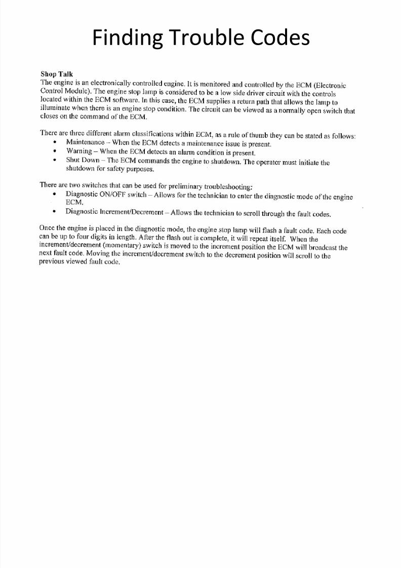
Finding Trouble Codes
Cummins Diagnostic Connector location. Communication difficulty between a laptop

7/17/2019 SV510 technical
http://slidepdf.com/reader/full/sv510-technical 45/87
and the engine usually means the 1 amp fuse has blown. This fuse should be replacedwith a 10 amp fuse.

7/17/2019 SV510 technical
http://slidepdf.com/reader/full/sv510-technical 46/87
Machine Fuses in the Battery Box There are fuses in two places, under the steering wheel next to the diagnosticswitches and here in the rear left side of the machine, next to the batteries.

7/17/2019 SV510 technical
http://slidepdf.com/reader/full/sv510-technical 47/87
You should always hear the battery relay kick in when the key switch is turned on.
Also in the battery area are the main grounds. The small black wire is ground for the

7/17/2019 SV510 technical
http://slidepdf.com/reader/full/sv510-technical 48/87
Cummins ECM, there is another ground (braided strap) at the ECM, it grounds to theblock. A loose ground will keep the engine form running.

7/17/2019 SV510 technical
http://slidepdf.com/reader/full/sv510-technical 49/87
Vibe Solenoid Grounds

7/17/2019 SV510 technical
http://slidepdf.com/reader/full/sv510-technical 50/87
The Drum
The main shaft, 23, runs in 90 Wt oil and is driven by motor, 14. Hydraulic oil can enter the drumf h ib b i i Oil f h d i b / 3 h h l k i h

7/17/2019 SV510 technical
http://slidepdf.com/reader/full/sv510-technical 51/87
from the vibe motor but it is rare. Oil from the drive gearbox/motor, 3, has no path to leak into thevibe cavity. Excess oil in the vibe will contact the weights, slow vibe speed and overheat the hydraulicsystem.
Lube of the vibe bearings is by gravity and requires the drum to be rolling. Static vibration for testing
should be brief. The odd rectangle shapes at the four corners of the vibe cavity are paddles thatcollect & pour oil on the bearings. The vibe can be ran static for testing but it should be kept to lessthan a minute, then shut off the vibe and roll two revolutions to re lube the shaft bearings beforecontinuing.
With normal care the bearings will rarely fail, a recent failure at 2600 hours revealed one perfect vibebearing and one burnt and seized. This happened due to rolling side ways on a gentle hill. The highside bearing had no oil. Always roll hills up & down not side to side.
f
7/17/2019 SV510 technical
http://slidepdf.com/reader/full/sv510-technical 52/87
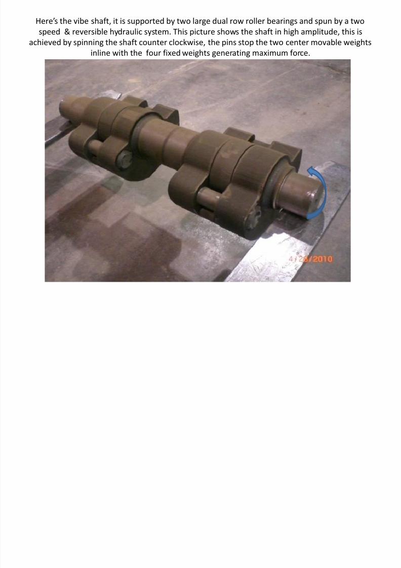
Here’s the vibe shaft, it is supported by two large dual row roller bearings and spun by a twospeed & reversible hydraulic system. This picture shows the shaft in high amplitude, this is
achieved by spinning the shaft counter clockwise, the pins stop the two center movable weightsinline with the four fixed weights generating maximum force.
By reversing the shaft’s rotation, the movable weights rotate half way around the shaft, hit thestop pins and assume low amplitude position. This happens fast and will cause loud clanging from

7/17/2019 SV510 technical
http://slidepdf.com/reader/full/sv510-technical 53/87
p p p p pp g gthe drum. As long a drum noise last only a second, occurs during starting, stopping or amplitudechange, it is normal. When running the vibrator the drum makes little noise other than hitting theground.
The shaft spins faster in Low amplitude, 2200 RPMS. In High amplitude the speed is limited to1650.
Vib b i l d bl

7/17/2019 SV510 technical
http://slidepdf.com/reader/full/sv510-technical 54/87
Vibe bearings are large, double rowbarrel roller bearings
If these bearings become mis aligned do not force realignment they can be damaged

7/17/2019 SV510 technical
http://slidepdf.com/reader/full/sv510-technical 55/87
If these bearings become mis-aligned do not force realignment, they can be damaged.The roller cage is a lose fit, once outside of the race the rollers can drop just a bit until
caught by the cage.

7/17/2019 SV510 technical
http://slidepdf.com/reader/full/sv510-technical 56/87
To get the rollers back inside the race press up on the two or three rollers thatare interfering with realignment.
Vibe system Operation and Trouble Shooting

7/17/2019 SV510 technical
http://slidepdf.com/reader/full/sv510-technical 57/87
Vibe system Operation and Trouble Shooting• We use a very reliable & simple system. The shaft is spun inside the drum by the vibe motor
causing powerful vibrations that are directed into the ground for compaction purposes.• A bi-directional two speed pump is coupled internally to the travel pump and driven by the
engine. Flow is to a fixed, bi-directional motor at the drum, coupled to the eccentric shaft.• With the vibe turned off, the pump swash plate is zeroed by springs and no flow or vibration
occurs. When the amplitude switch is turned to low amplitude the solenoid control valvesends oil to one of the 2 vibe pump servos. This establishes the direction of shaft rotation(amplitude) and flow rate (shaft rpm) Servo stops determine the shaft speed in eachdirection.
• Since we vary the force by shifting the weights we also vary the speed to prevent overstressing the drum. In hi amplitude the shaft turns at 1650 RPMs. In low amplitude the shaftturns at 2200 RPMs due to servo stop adjustment. The vibe pump control solenoid and theamplitude switch can be mis-wired or the hoses to the vibe motor can be swapped and theshaft will turn at 2200 in the wrong direction, making high amplitude at high speed. Thisextreme force can destroy the drum, use care when making these connections. Justremember, high force never goes with high speed. Correct equations is high amplituderequires low speed, low amplitude requires high speed. This is true in all variable amplitudeSakai machines.
• To test vibe operation the actual shaft speed must be confirmed, this is done with a vibro-tach.
There are pressure test ports on the vibe pump, they can determine if the relief pressures are

7/17/2019 SV510 technical
http://slidepdf.com/reader/full/sv510-technical 58/87
correct. Relief is set to 3500 psi. To check, cap off the work ports and test with a 6000 psi gauge.Since the shaft is supported by bearings with no way to stall the shaft, working vibe pressure isdifficult to evaluate. The best way to verify proper vibe operation is to measure shaft speed. For
that, get a vibro-tach, it can convert vibrations into RPMs.

7/17/2019 SV510 technical
http://slidepdf.com/reader/full/sv510-technical 59/87
These can be purchased at small engine distributors, a common use is to measure rpms of smallengines. Check local Briggs & Stratton dealer. To check low amplitude (high speed) start by setting
the dial to 2200 as shown.

7/17/2019 SV510 technical
http://slidepdf.com/reader/full/sv510-technical 60/87
Practice using one of these before you try in front of a customer! Best way to practice is measurevpm on a known source. Electric motors, single cylinder engines or a new roller.

7/17/2019 SV510 technical
http://slidepdf.com/reader/full/sv510-technical 61/87
If the tach isn’t in resonance with the shaft the movement of the wire will be erratic. Onceresonance is found the pattern made by the moving wire will settle and become consistant, then
read the value indicated by the pointer.

7/17/2019 SV510 technical
http://slidepdf.com/reader/full/sv510-technical 62/87
Two speed, reversible vibration pump main components
If the vibe function will not work the manual over ride is useful to determine if

7/17/2019 SV510 technical
http://slidepdf.com/reader/full/sv510-technical 63/87
If the vibe function will not work, the manual over-ride is useful to determine ifthe fault is in the hydraulic or the control system. Use a small tool and depressthe pin shown. This moves the spool and the shaft will spin, you can do this onthe shop floor at idle. Check in both directions , if the vibrator turns the fault is
not in the hydraulic system.

7/17/2019 SV510 technical
http://slidepdf.com/reader/full/sv510-technical 64/87
Oil leaving the top work port spins the shaft clock wise at 1650 rpms for high amplitude. Thisspeed is set by the motors capacity and the displacement setting of the vibe pump servo screw.When oil flows from the bottom work port the shaft spins counter clock wise. This changes theshape of the shaft and a separate displacement set screw sets the speed to 2200 rpms for low
amplitude. You should never need to adjust vibe pump displacement set screws.
A quick test of the switches can help determine a fault with the FNR switch Place Grip

7/17/2019 SV510 technical
http://slidepdf.com/reader/full/sv510-technical 65/87
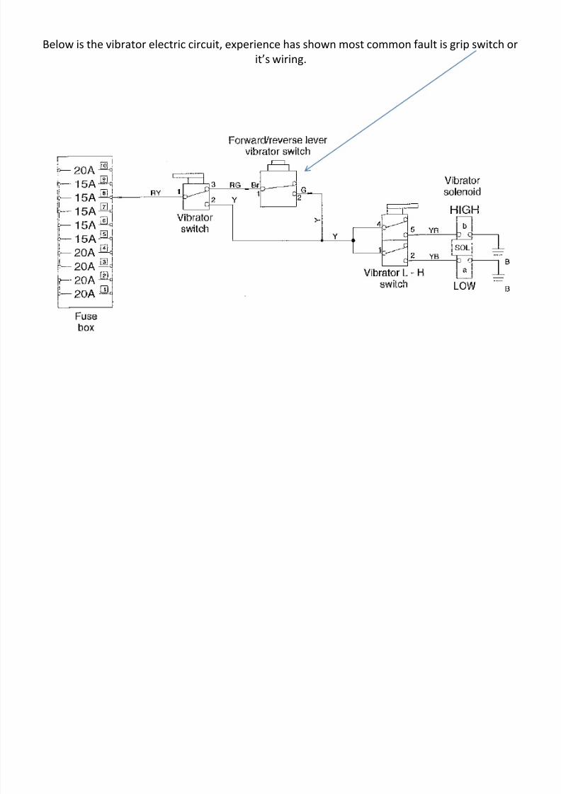
A quick test of the switches can help determine a fault with the FNR switch. Place Grip/ CONT switch (middle switch) in CONT. Set throttle to full and drive forward or
reverse. Vibration should occur whenever the FNR leaves neutral. If the vibe starts inthis mode then the grip switch or its wiring is the fault.
7/17/2019 SV510 technical
http://slidepdf.com/reader/full/sv510-technical 66/87
Below is the vibrator electric circuit, experience has shown most common fault is grip switch orit’s wiring.
Travel Hydraulic System

7/17/2019 SV510 technical
http://slidepdf.com/reader/full/sv510-technical 67/87
Travel Hydraulic System
To remove, take the pump off with the bell housing cover attached.

7/17/2019 SV510 technical
http://slidepdf.com/reader/full/sv510-technical 68/87
SV505 Tra el S stem

7/17/2019 SV510 technical
http://slidepdf.com/reader/full/sv510-technical 69/87
SV505 Travel System
• Travel control is by mechanical cable controlling a manual displacementvalve built into the travel pump.
• Travel pump is variable and reversible. This allows direction change andtravel speed variation both via the FNR lever.
• Travel system is Parallel Circuit.• Travel relief valves (2) are housed in the pump. This makes it possible to
isolate and test the travel pump alone.• A Rabbit Turtle switch changes displacement of only the rear motor to
give two speed ranges. Rabbit is for transport and flat ground operation,turtle allows better performance on slopes.
•
Rabbit / Turtle speed can be switched on the go.

7/17/2019 SV510 technical
http://slidepdf.com/reader/full/sv510-technical 70/87
SV505 Axle & motor
Common mistakes that are not

7/17/2019 SV510 technical
http://slidepdf.com/reader/full/sv510-technical 71/87
problems• A high percentage of travel complaints result in no fault being found.• Watch for these false indicators of travel problems.• When I push down on the blade, the front drum spins and the tires stop.• When I back up a hill or truck ramps the tires spin and the drum won’t
pull.• When going forward up a steep slope the machine just stops, no load on
the engine.• Yesterday it pulled great, now it won’t move. • I am noticing sluggish travel performance, gets worse when hot.• It looks like the drum is trying to turn but the tires seem to be stuck.• I have a 505D, I get stuck in the mud all the time because my tires are not
pulling.
• See below for explanation of these issues.
Propulsion

7/17/2019 SV510 technical
http://slidepdf.com/reader/full/sv510-technical 72/87
Propulsion
• When I push down on the blade, the front drum spins and the tires stop.• SV505’s use a single pump driving two motors, one at the axle and one at the left
side of the drum. Each motor is capable of digesting full pump flow. With thissystem if too much down pressure is placed on the blade, the drum looses tractionfrom loss of weight / friction. Since blade down pressure puts more weight on theaxle the imbalance becomes greater. Oil will follow the path of least resistance, thedrum spins until the blade is picked up enough to bring weight back to the drum.
This is Normal• When I back up a hill or truck ramps, the tires spin and the drum won’t pull. • Same thing, different direction. Backing up a hill does the same thing too much
blade down pressure does, causing an imbalance in traction between the twodrives. When backing up a slope the machine center of gravity shift’s toward the
bottom of the hill. This shifts weight from the tires to the drum. When the tiresloose enough weight / friction they will slip and it’s the path of least resistancerule again, tires spin and the drum stops.This is Normal

7/17/2019 SV510 technical
http://slidepdf.com/reader/full/sv510-technical 73/87
• When going forward up a steep slope the machine just stops and the engine goesto nearly high idle .
• Sakai uses multifunction relief valves in the travel pump. In Turtle mode when
travel relief is reached (6000PSI) the valve automatically reduces pumpdisplacement. A balance is reached where minimum flow is produced yet reliefpressure is met. This keeps the engine RPMS up, and passed less oil over the reliefvalve while maintaining relief pressure in the circuit. Don’t be fooled by theengine not pulling down, when it hits relief the engine will unload go to high idleand the machine will stop , this is normal. It’s because the pump is only strokedenough to maintain relief pressure with virtually no flow. A stall does not alwaysoccur, if flow is high when relief is reached the engine often will die.
• Yesterday it pulled great, now it won’t move. • I am noticing sluggish travel performance, gets worse when hot.• Both of these could be an open tow valve, first case it’s wide open. Second
example it’s only cracked open.• Always check tow valve first on any travel problem.
It looks like the drum is trying to turn but the tires seem to be stuck.

7/17/2019 SV510 technical
http://slidepdf.com/reader/full/sv510-technical 74/87
Possibly the brakes are set. There is a micro switch that operates off of the brake pedallinkage. If the brake gets used and the switch doesn’t return to its normal position thebrakes may be on. The pedal switch doesn’t light up the dash park indicator light. Notnormal but easy to check, remember, there’s no brake in the drum.
Examine the diagram below, it’s a basic representation of the 505 travel system.Clearly, you can see there is nothing in the circuit to influence the path of travel oil

7/17/2019 SV510 technical
http://slidepdf.com/reader/full/sv510-technical 75/87
flow. That is accomplished only by the ground. If either drive depicted below losestraction, it will spin and the other drive will lose all power / torque and the machine
will stop.
If either travel motor looses enough traction (it’s torque becomes greater than it’s friction to theground) that drive will spin. Once that starts it’s speed increases and momentum insures all travel
oil flow will pass through this motor while oil in the motor with traction is static

7/17/2019 SV510 technical
http://slidepdf.com/reader/full/sv510-technical 76/87
oil flow will pass through this motor while oil in the motor with traction is static.Most rollers on the market work this way, and on level ground this system works well. When
faced with traction complaints knowing how it works will keep you from making an expensivemistake.
This knowledge is meant to prevent unnecessary troubleshooting / tear down when acustomer complains of these symptoms.

7/17/2019 SV510 technical
http://slidepdf.com/reader/full/sv510-technical 77/87
Measuring Travel Performance• The best way to diagnose travel performance is not with gauges or flow raters but
by measuring the speed. Spec top travel speed is 6 mph. To find travel speedmeasure & mark off 88 feet. With a driver to help, time the 505 through the 88foot trap. Make sure travel through the trap is at full speed, not accelerating but atfull speed when he enters and leaves the trap.
• Record the time in seconds. Now divide 60 by the seconds required.• Example: Time thru 88 foot trap = 12 seconds•
12 into 60 = 5 mph. This means there is a problem, time thru trap should be 10seconds.• Perform the test a few times to verify consistency.• Perform test with hot oil.• To determine if the problem is pump or motors, cap the pump and pressure test at
idle, if relief pressure (6000 psi) is reached then the problem is in one of the
motors.• Perform leak test on motors, both should be less than 1.5 GPM.• For further help, call me, 770 712 6168, by the way, this will work on anything if
you have the travel speed spec.

7/17/2019 SV510 technical
http://slidepdf.com/reader/full/sv510-technical 78/87
SV510 Travel with traction control
How it works

7/17/2019 SV510 technical
http://slidepdf.com/reader/full/sv510-technical 79/87
• In the previous slide, key drive system components are described. The 510 drumwas up graded with a variable motor and fitted to a Fairfield gear box. Both front &rear 510 motors are the same torque & displacement. The drum gearbox now has
the same gear ratio as the axle. This gives the exact same torque capability at bothdrives. You will again notice there are no orifices / flow dividers to influence flow.The motors however can change their displacement form 85 to 16 cc perrevolution under load. This ability is used to influence pump flow.
• The traction control system simply adjust torque at the drives to prevent slippagewhere traction is weak and apply all available torque where traction is strong. Wedo this by assigning a master drive and a slave drive depending on direction oftravel. The slave drive is always the one with less traction. The computer preventsslippage in the slave drive by reducing it’s displacement, making it weak.
• Forward travel assigns the axle as the master drive, this means the computer willnot allow the slave drive to go faster than the master drive. As the roller starts up a
slope its center of gravity shifts down hill. This is proportional to the degree ofslope, in forward on a 30 degrees slope, 75% of the machines weight rest on thetires, only 25% rest on the drum. If the speed sensors “see“ the slave drive (drum)begin to out run the master, then the slave drive displacement is reduced by thecomputer until its speed is the same as the master. This effectively applies torqueonly where it is useful, avoiding the path of least resistance.
How it works

7/17/2019 SV510 technical
http://slidepdf.com/reader/full/sv510-technical 80/87
How it works
• When backing the drum becomes master, because that places the drum in
the position of greatest traction.• Notice in the drawing a connection from the FNR / back up alarm switch.
The back up alarm switch is used to determine master drive. If the back upalarm isn’t engaged the system assumes travel is forward. Alarm soundingequals travel in reverse.
• Both motors have speed sensors and are connected to a Plus 1 SauerDanfoss controller. The computer controls speed of the slave to matchspeed of the master. If the slave motor begins to lose traction and spinsfaster than the master drive, the computer decreases the slave motordisplacement further. At first this counter intuitive. By decreasing motor
displacement normally you increase it’s speed. But because the slave driveis in contact with the ground the drive can’t increased its speed, it justgets too weak to break lose, exactly the result we wanted. This allows fullsystem pressure to build in both drives.

7/17/2019 SV510 technical
http://slidepdf.com/reader/full/sv510-technical 81/87
Traction Controller

7/17/2019 SV510 technical
http://slidepdf.com/reader/full/sv510-technical 82/87
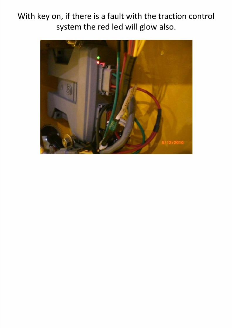
With key on and no faults, a green led will glow.
With key on if there is a fault with the traction control
7/17/2019 SV510 technical
http://slidepdf.com/reader/full/sv510-technical 83/87
With key on, if there is a fault with the traction controlsystem the red led will glow also.
l d

7/17/2019 SV510 technical
http://slidepdf.com/reader/full/sv510-technical 84/87
Fault codes• When the key is turned on the red led flashes briefly then goes off and the green
led is lit steady. This indicates no faults, system normal.• Look for 2 digit codes, slow flashes followed by fast flashes.• Common faults are broken connection (wiring or connectors) or speed sensors.

7/17/2019 SV510 technical
http://slidepdf.com/reader/full/sv510-technical 85/87
SV510 traction Concept
7/17/2019 SV510 technical
http://slidepdf.com/reader/full/sv510-technical 86/87
Why it works
• The lower drive doesn’t spin out because it’s carrying 75% of the machines weightthus has good traction. The drive at the top of the hill can’t spin because eventhough it may be getting 6000 psi and only carrying 25% of the load, the computerhas adjusted the motor displacement so low (so it becomes weak) that it can’tbreak lose from the limited traction at the top of the hill. The system adjust bothmotor displacements hundreds of times per minute and works seamlessly. There isno synchronization of the drives required, the parallel hydraulic circuit does thatnaturally. The system is capable of 27 to 30 degree slope work in forward orreverse depending on conditions.
• To get best performance with an combo drum remove the shell kit. The extraweight and drum diameter will reduce slope performance.
C l i

7/17/2019 SV510 technical
http://slidepdf.com/reader/full/sv510-technical 87/87
Conclusion• We’ve covered the basics of the SV505 & 510. Always keep in mind when troubleshooting
Sakai machines these basic rules.• 1 There might be nothing wrong, I see this often.• 2 Verify all the basic stuff first, you will find the problem 90% of the time by doing so.• 3 Remember, soil conditions must be right for compaction, too much or little moisture and
soil will not compact.• 4 There are many informational decals on the machine, mainly service & towing info.• 5 Vibrator circuit connections are critical, hooking up backwards can cause major damage.• 6 Brake pedal is for emergency only.• 7 Keeping the cooling system clean is critical to long life.• 8 Keep fuel traps cleaned out and tank full for storage.•
• Keep my cell number in your phone, Gerry Petty 770 712 6168.
![Civic Reception House Nagoya EntranceTechnical Tour2 Technical Tour3 Technical Tour4 Technical Tour5 [12] Technical Tour6 Technical Tour7 Technical Tour8 Technical Tour9 Technical](https://img.pdfslide.us/doc/110x75/60511276b5492f765a3fd03c/civic-reception-house-nagoya-entrance-technical-tour2-technical-tour3-technical.jpg)