Embed Size (px)
Citation preview

July 2013
New Product ReleaseSV1307-1E
Motion control made simpler
High-speed control is achieved by
combining the SSCNET III/H compatible
MELSERVO-J4 series amplifiers with
this Simple Motion module.
This module features advanced Motion
control with the flexibility and ease of
use of the MELSEC-L series.
SSCNET III/H CompatibleMELSEC-L Series Simple Motion ModuleLD77MS16/LD77MS4/LD77MS2
MDOC (1307)
Mitsubishi has invented an original servo system synchronous network “SSCNET III/H” in pursuit of high response and reliability. The SSCNET III/H is an optical network that achieves smooth, high-response and high-accuracy operation.
• Used for various applications Advanced and wide-range Motion controls are available, such as synchronous and cam control.
• Applied to various machines The synchronous encoder and Mark detection function are equipped as standard.
• Effortless debugging and quick startup Simple settings without programming are achieved in collaboration with Mitsubishi's MELSOFT series Engineering environment.
• Future system expansion Program resources are utilized efficiently.
Achieving advanced Motion controls but simple to use just like the positioning module
New publication, effective July 2013Specifications are subject to change without notice.

1
Features
Positioning controlPositioning control can be performed easily by starting the positioning data in Motion profile table, initiated by the instruction in the sequence program. Various controls, such as linear interpolation control, 2-axis circular interpolation control, fixed-pitch feed control and continuous trajectory control are provided for a wide variety of applications.
Synchronous, Cam controlUsing software to replace machine mechanisms, such as the gear, shaft, speed change gear and cam achieves synchronous control, just by setting parameters. Various cam patterns are easily created without complex program.
Speed-torque control (Tightening & press-fit control)Tension control applications such as unwinding and rewinding axes can be performed easily. Since the current position is stored even during Speed-torque control, the positioning on the absolute position coordinates is possible after switching from Speed-torque control back to position control.
The Simple Motion module is simple to use just like the positioning module while being capable of performing various advanced Motion controls with only sequence programs, such as synchronous/cam/speed-torque (tightening & press-fit) control, which are unavailable with the positioning modules.
MR-J4-BPositioning dataSequence program
Positioning data No.1
Program start
Reset of device in operation
M0 DX3C
BUSYMOVP K1
U3\G1500
RST M0
SET Y40
No.
1
2
Operation pattern
1: CONT
<Positioning comment>
0: END
<Positioning comment>
01h: ABS Linear 1
01h: ABS Linear 1
0: 1000
0: 1000
0: 1000
0: 1000
200000.0 μm
-200000.0 μm
20000.00 mm/min
10000.00 mm/min
Control system Acceleration time No. Deceleration time No. Positioning address Command speed
Servo motor
Unwinding axis
Rewinding axis
Tension detector
Tension detector
Printer
Input shaft Input shaft Input shaft
(Main shaft gear)
(Main shaft gear)
(Main shaft gear)
(Cam)
Output shaft
(Clutch)
(Cam)
Output shaft
(Clutch)
(Cam)
Output shaft
(Clutch)
Food
Plastic material
Film index axes
Conveyor
Sealing & cutting axis
Synchronous encoder
Synchronous encoder
Cam pattern
Spe
ed
Cam axis length per cycle
Advanced and wide-range Motion control with ease of use
LD77MS16 LD77MS4 LD77MS2
2
Simple Motion Module LD77MS16/LD77MS4/LD77MS2
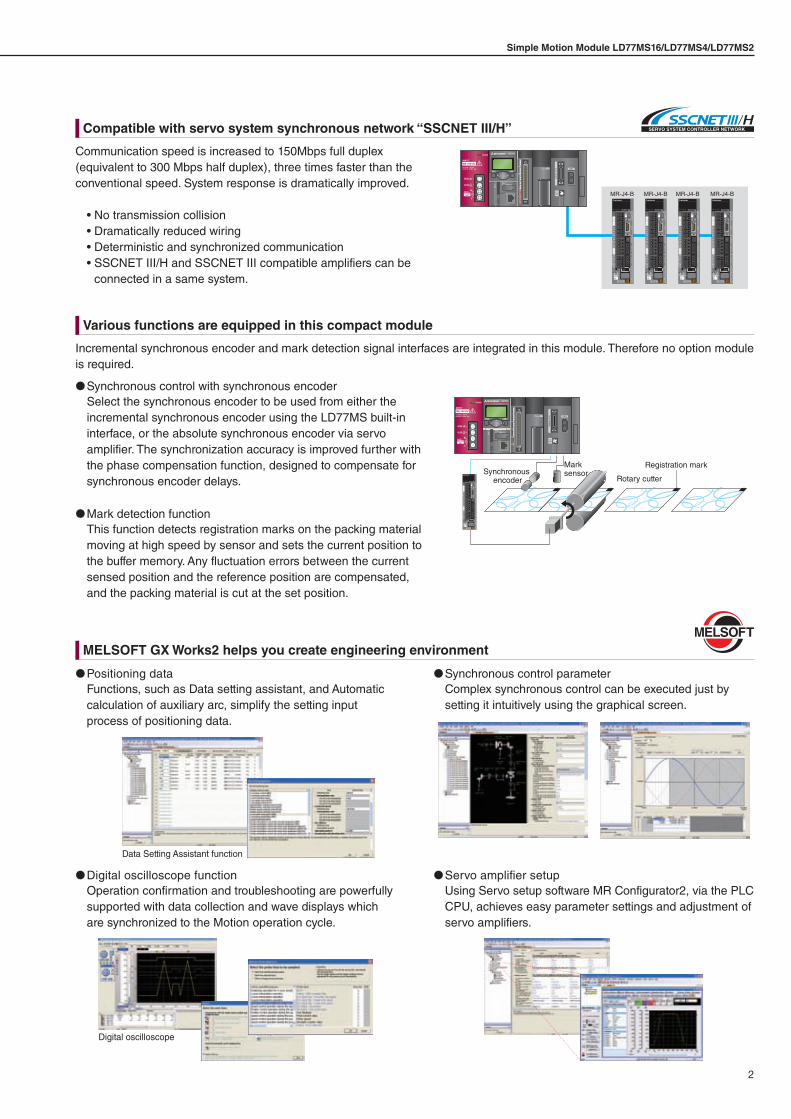
Communication speed is increased to 150Mbps full duplex (equivalent to 300 Mbps half duplex), three times faster than the conventional speed. System response is dramatically improved.
• No transmission collision• Dramatically reduced wiring• Deterministic and synchronized communication• SSCNET III/H and SSCNET III compatible amplifiers can be
connected in a same system.
Incremental synchronous encoder and mark detection signal interfaces are integrated in this module. Therefore no option module is required.
Positioning dataFunctions, such as Data setting assistant, and Automatic calculation of auxiliary arc, simplify the setting input process of positioning data.
Digital oscilloscope functionOperation confirmation and troubleshooting are powerfully supported with data collection and wave displays which are synchronized to the Motion operation cycle.
Synchronous control parameterComplex synchronous control can be executed just by setting it intuitively using the graphical screen.
Servo amplifier setupUsing Servo setup software MR Configurator2, via the PLC CPU, achieves easy parameter settings and adjustment of servo amplifiers.
Synchronous control with synchronous encoderSelect the synchronous encoder to be used from either the incremental synchronous encoder using the LD77MS built-in interface, or the absolute synchronous encoder via servo amplifier. The synchronization accuracy is improved further with the phase compensation function, designed to compensate for synchronous encoder delays.
Mark detection functionThis function detects registration marks on the packing material moving at high speed by sensor and sets the current position to the buffer memory. Any fluctuation errors between the current sensed position and the reference position are compensated, and the packing material is cut at the set position.
Registration mark
Rotary cutter
Mark sensorSynchronous
encoder
MR-J4-B MR-J4-B MR-J4-B MR-J4-B
Digital oscilloscope
Data Setting Assistant function
Compatible with servo system synchronous network “SSCNET III/H”
Various functions are equipped in this compact module
MELSOFT GX Works2 helps you create engineering environment
3
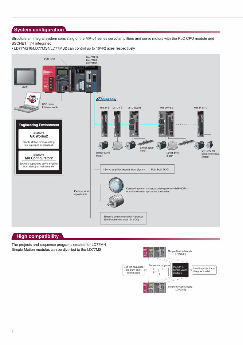
System configuration
Structure an integral system consisting of the MR-J4 series servo amplifiers and servo motors with the PLC CPU module and SSCNET III/H integrated. • LD77MS16/LD77MS4/LD77MS2 can control up to 16/4/2 axes respectively.
High compatibility
The projects and sequence programs created for LD77MH Simple Motion modules can be diverted to the LD77MS. Simple Motion Module
(LD77MH)
Sequence program
Simple Motion Module(LD77MS)
Projects for Simple Motion modules
Use the sequenceprogram from prior models
Use the project from the prior model
USB cableEthernet cable
LD77MS16LD77MS4LD77MS2
PLC CPU
External command signal (4 points)EMI Forced stop input (24 VDC)
<Servo amplifier external input signal >
Connecting either a manual pulse generator (MR-HDP01) or an incremental synchronous encoder External input
signal cable
GOT
FLS, RLS, DOG
Engineering Environment
Simple Motion module setting tool equipped as standard
MELSOFT
GX Works2
Software supporting servo amplifier from startup to maintenance
MR Configurator2MELSOFT
MR-J4-B-RJ
Q171ENC-W8Serial synchronous encoder
MR-J4W2-B
Linear servo motor
MR-J4-B
Rotary servo motor
MR-J4-B
Direct drive motor
MR-J4W3-B

4
Simple Motion Module LD77MS16/LD77MS4/LD77MS2
Module specification
ItemSpecifications
LD77MS16 LD77MS4 LD77MS2
Servo amplifier connection system SSCNET III/H (1 system)Maximum overall distance [m(ft.)] SSCNET III/H : 1600 (5249.34), SSCNET III : 800 (2624.67)Maximum distance between stations [m(ft.)] SSCNET III/H : 100 (328.08), SSCNET III : 50 (164.04)PERIPHERAL I/F Via CPU module (USB, Ethernet)
Inte
rfac
e w
ith e
xter
nal d
evic
es
External input signal/ Switching signal (CHG)
Number of input points 4 points 2 pointsInput method Positive common/Negative common shared (Photocoupler)Rated input voltage/Rated input current
24 VDC/Approx. 5 mA
Operating voltage range 21.6 to 26.4 VDC (24 VDC ±10 %, ripple ratio 5 % or less)ON voltage/current 17.5 VDC or more/3.5 mA or moreOFF voltage/current 5 VDC or less/0.9 mA or lessInput resistance Approx. 5.6 kΩResponse time 1 ms or lessRecommended wire size AWG24 (0.2 mm2)
Forced stop input signal (EMI)
Number of input points 1 point (EMI)Input method Positive common/Negative common shared (Photocoupler)Rated input voltage/Rated input current
24 VDC/Approx. 2.4 mA
Operating voltage range 20.4 to 26.4 VDC (24 VDC +10 %/-15 %, ripple ratio 5 % or less)ON voltage/current 17.5 VDC or more/2.0 mA or moreOFF voltage/current 1.8 VDC or less/0.18 mA or lessInput resistance Approx. 10 kΩResponse time 1 ms or lessRecommended wire size AWG24 (0.2 mm2)
Manual pulse generator/Incremental synchronous encoder signal
Signal input formPhase A/Phase B (magnification by 4/magnification by 2/magnification by 1),
PLS/SIGN
Differential-output type
Input frequency Up to 1 Mpps (After magnification by 4, up to 4 Mpps)High-voltage 2.0 to 5.25 VDCLow-voltage 0 to 0.8 VDCDifferential-voltage ±0.2 VCable length [m(ft.)] Up to 30 (98.43)
Voltage-output/ Open-collector type (5 VDC)
Input frequency Up to 200 kpps (After magnification by 4, up to 800 kpps)High-voltage 3.0 to 5.25 VDCLow-voltage 0 to 1.0 VDCCable length [m(ft.)] Up to 10 (32.81)
Number of I/O occupying points 32 points (I/O allocation: intelligent function module: 32 points)Number of module occupied slots 25VDC internal current consumption [A] 0.7 0.55Mass [kg] 0.22Exterior dimensions [mm(inch)] 90.0 (3.54) (H) × 45.0 (1.77) (W) × 95.0 (3.74) (D)

5
Control specification
ItemSpecifications
LD77MS16 LD77MS4 LD77MS2 (Note-3)
Number of control axes Up to 16 axes Up to 4 axes Up to 2 axes
Operation cycle 0.88 ms/1.77 ms (Note-1) 0.88 ms 0.88 ms
Interpolation function Linear interpolation (Up to 4 axes), Circular interpolation (2 axes)
Control modesPTP (Point To Point) control, Trajectory control (both linear and circular can be set),Speed control, Speed-position switching control, Position-speed switching control,
Speed-torque controlAcceleration/deceleration process Trapezoidal acceleration/deceleration, S-curve acceleration/decelerationCompensation function Backlash compensation, Electronic gear, Near pass functionSynchronous control External encoder, Cam, Phase compensation, Cam auto-generationControl unit mm, inch, degree, PLS
Number of positioning data600 data (positioning data No. 1 to 600)/axis
(Can be set with MELSOFT GX Works2 or Sequence program.)Backup Parameters, positioning data, and block start data can be saved on flash ROM (battery-less backup)
OPR controlMachine OPR control
Near-point dog method, Count method 1, Count method 2, Data set method, Scale origin signal detection method
Fast OPR control ProvidedSub functions OPR retry, OP shift
Positioning control
Position control
Linear control1-axis linear control, 2-axis linear interpolation control,
3-axis linear interpolation control, 4-axis linear interpolation control (Note-4) (Composite speed, Reference axis speed)
Fixed-pitch feed control1-axis fixed-pitch feed control, 2-axis fixed-pitch feed control, 3-axis fixed-pitch feed control,
4-axis fixed-pitch feed control2-axis circular interpolation control
Sub point designation, Center point designation
Speed control 1-axis speed control, 2-axis speed control, 3-axis speed control, 4-axis speed controlSpeed-position switching control INC mode, ABS modePosition-speed switching control INC mode
Other controls
Current value change Positioning data, Start No. for a current value changing NOP instruction ProvidedJUMP instruction Unconditional JUMP, Conditional JUMPLOOP, LEND Provided
High-level positioning control Block start, Condition start, Wait start, Simultaneous start, Repeated start
Manual controlJOG operation ProvidedInching operation ProvidedManual pulse generator Possible to connect 1 module (Incremental), Unit magnification (1 to 10000 times)
Expansion control Speed-torque control Speed control without positioning loops, Torque control, Tightening & press-fit controlAbsolute position system Made compatible by setting battery to servo amplifier
Synchronous encoder interfaceUp to 4 channels
(Total of the internal interface, interface via servo amplifier, and interface via the PLC CPU)Internal interface 1 channel (Incremental)
Functions that limit control
Speed limit function Speed limit value, JOG speed limit valueTorque limit function Torque limit value_same setting, Torque limit value_individual settingForced stop Valid/Invalid settingSoftware stroke limit function Movable range check with current feed value, Movable range check with machine feed valueHardware stroke limit function Provided
Functions that change control details
Speed change function ProvidedOverride function ProvidedAcceleration/deceleration time change function
Provided
Torque change function ProvidedTarget position change function Target position address and speed to target position are changeable
Other functions
M code output function ProvidedStep function Deceleration unit step, Data No. unit stepSkip function Via PLC CPU, Via external command signalTeaching function Provided
Mark detection function Continuous Detection mode, Specified Number of Detections mode, Ring Buffer modeMark detection signal 4 points 2 pointsMark detection setting 16 4
Optional data monitor function 4 points/axisAmplifier-less operation function Provided
Digital oscilloscope function (Note-2) Bit data 16 channels, Word data 16 channels
Bit data 8 channels,Word data 4 channels
(Note-1): Default value is 1.77 ms. If necessary, check the operation time and change it to 0.88 ms.(Note-2): 8 CH word data and 8 CH bit data can be displayed as a wave form in real time.(Note-3): The maximum number of control axes for LD77MS2 is two axes. Use LD77MS4 or LD77MS16 to control three or more axes.(Note-4): 4-axis linear interpolation control is enabled only at the reference axis speed.
6
Simple Motion Module LD77MS16/LD77MS4/LD77MS2
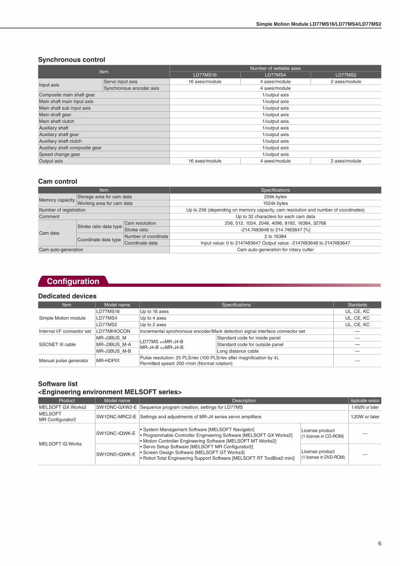
Synchronous control
ItemNumber of settable axes
LD77MS16 LD77MS4 LD77MS2
Input axisServo input axis 16 axes/module 4 axes/module 2 axes/moduleSynchronous encoder axis 4 axes/module
Composite main shaft gear 1/output axisMain shaft main input axis 1/output axisMain shaft sub input axis 1/output axisMain shaft gear 1/output axisMain shaft clutch 1/output axisAuxiliary shaft 1/output axisAuxiliary shaft gear 1/output axisAuxiliary shaft clutch 1/output axisAuxiliary shaft composite gear 1/output axisSpeed change gear 1/output axisOutput axis 16 axes/module 4 axes/module 2 axes/module
Cam controlItem Specifications
Memory capacityStorage area for cam data 256k bytesWorking area for cam data 1024k bytes
Number of registration Up to 256 (depending on memory capacity, cam resolution and number of coordinates)Comment Up to 32 characters for each cam data
Cam dataStroke ratio data type
Cam resolution 256, 512, 1024, 2048, 4096, 8192, 16384, 32768Stroke ratio -214.7483648 to 214.7483647 [%]
Coordinate data typeNumber of coordinate 2 to 16384Coordinate data Input value: 0 to 2147483647 Output value: -2147483648 to 2147483647
Cam auto-generation Cam auto-generation for rotary cutter
Dedicated devicesItem Model name Specifications Standards
Simple Motion moduleLD77MS16 Up to 16 axes UL, CE, KCLD77MS4 Up to 4 axes UL, CE, KCLD77MS2 Up to 2 axes UL, CE, KC
Internal I/F connector set LD77MHIOCON Incremental synchronous encoder/Mark detection signal interface connector set —
SSCNET III cableMR-J3BUS_M
LD77MS ⇔MR-J4-BMR-J4-B ⇔MR-J4-B
Standard code for inside panel —MR-J3BUS_M-A Standard code for outside panel —MR-J3BUS_M-B Long distance cable —
Manual pulse generator MR-HDP01Pulse resolution: 25 PLS/rev (100 PLS/rev after magnification by 4), Permitted speed: 200 r/min (Normal rotation)
—
Software list<Engineering environment MELSOFT series>
Product Model name Description Applicable versionMELSOFT GX Works2 SW1DNC-GXW2-E Sequence program creation, settings for LD77MS 1.492N or laterMELSOFTMR Configurator2
SW1DNC-MRC2-E Settings and adjustments of MR-J4 series servo amplifiers 1.20W or later
MELSOFT iQ Works
SW1DNC-IQWK-E• System Management Software [MELSOFT Navigator]• Programmable Controller Engineering Software [MELSOFT GX Works2]• Motion Controller Engineering Software [MELSOFT MT Works2]• Servo Setup Software [MELSOFT MR Configurator2]• Screen Design Software [MELSOFT GT Works3]• Robot Total Engineering Support Software [MELSOFT RT ToolBox2 mini]
License product(1 license in CD-ROM)
—
SW1DND-IQWK-ELicense product(1 license in DVD-ROM)
—
Configuration
July 2013
New Product ReleaseSV1307-1E
Motion control made simpler
High-speed control is achieved by
combining the SSCNET III/H compatible
MELSERVO-J4 series amplifiers with
this Simple Motion module.
This module features advanced Motion
control with the flexibility and ease of
use of the MELSEC-L series.
SSCNET III/H CompatibleMELSEC-L Series Simple Motion ModuleLD77MS16/LD77MS4/LD77MS2
MDOC (1307)
Mitsubishi has invented an original servo system synchronous network “SSCNET III/H” in pursuit of high response and reliability. The SSCNET III/H is an optical network that achieves smooth, high-response and high-accuracy operation.
• Used for various applications Advanced and wide-range Motion controls are available, such as synchronous and cam control.
• Applied to various machines The synchronous encoder and Mark detection function are equipped as standard.
• Effortless debugging and quick startup Simple settings without programming are achieved in collaboration with Mitsubishi's MELSOFT series Engineering environment.
• Future system expansion Program resources are utilized efficiently.
Achieving advanced Motion controls but simple to use just like the positioning module
New publication, effective July 2013Specifications are subject to change without notice.
Safety WarningTo ensure proper use of the products listed in this catalog, please be sure to read the instruction manual prior to use.
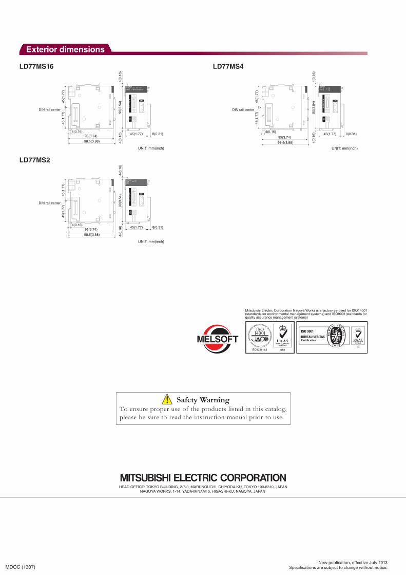
Exterior dimensions
LD77MS16
LD77MS2
LD77MS4
LD77MS16RUNERR.
AX 19 10111213141516
2 3 4 5 6 7 8
PULSER
CN1
95(3.74)45(1.77)
90(3
.54)
4(0.
16)
4(0.
16) 8(0.31)
45(1
.77)
45(1
.77)
DIN rail center
98.5(3.88)
4(0.16)
UNIT: mm(inch)
PULSER
CN1
LD77MS2RUNERR.
AX 12
45(1
.77)
DIN rail center
95(3.74)45(1.77)
90(3
.54)
4(0.
16)
4(0.
16) 8(0.31)
45(1
.77)
98.5(3.88)
4(0.16)
UNIT: mm(inch)
PULSER
CN1
LD77MS4RUNERR.
AX1234
45(1
.77)
DIN rail center
95(3.74)45(1.77)
90(3
.54)
4(0.
16)
4(0.
16) 8(0.31)
45(1
.77)
98.5(3.88)
4(0.16)
UNIT: mm(inch)