Embed Size (px)
Citation preview
9 9 5 0 0 - 1 0 4 9 1 - 0 1 E
UF50

FOREWORDThis manual contains an introductory description onthe SUZUKI UF50/UF50Z and procedures for its in-spection, service, and overhaul of its main components.Other information considered as generally known is notincluded.Read the GENERAL INFORMATION section to famil-iarize yourself with the motorcycle and its maintenance.Use this section as well as other sections as a guidefor proper inspection and service.This manual will help you know the motorcycle betterso that you can assure your customers of fast and reli-able service.
This manual has been prepared on the basisof the latest specifications at the time of publi-cation. If modifications have been made sincethen, differences may exist between the con-tent of this manual and the actual motorcycle.Illustrations in this manual are used to showthe basic principles of operation and work pro-cedures. They may not represent the actualmotorcycle exactly in detail.This manual is written for persons who haveenough knowledge, skills and tools, includingspecial tools, for servicing SUZUKI motorcycles.If you do not have the proper knowledge andtools, ask your authorized SUZUKI motorcycledealer to help you.
Inexperienced mechanics or mechanics with-out the proper tools and equipment may notbe able to properly perform the services de-scribed in this manual. Improper repair mayresult in injury to the mechanic and may ren-der the motorcycle unsafe for the rider andpassenger.
© COPYRIGHT SUZUKI MOTOR ESPAÑA, S.A. 2000
GROUP INDEX
GENERAL INFORMATION
PERIODIC MAINTENANCE
ENGINE
FUEL AND LUBRICATIONSYSTEM
CHASSIS
ELECTRICAL SYSTEM
SERVICING INFORMATION
UF50K1 AND UF50ZK1 (’01-MODEL)
2
1
3
4
5
6
7
8
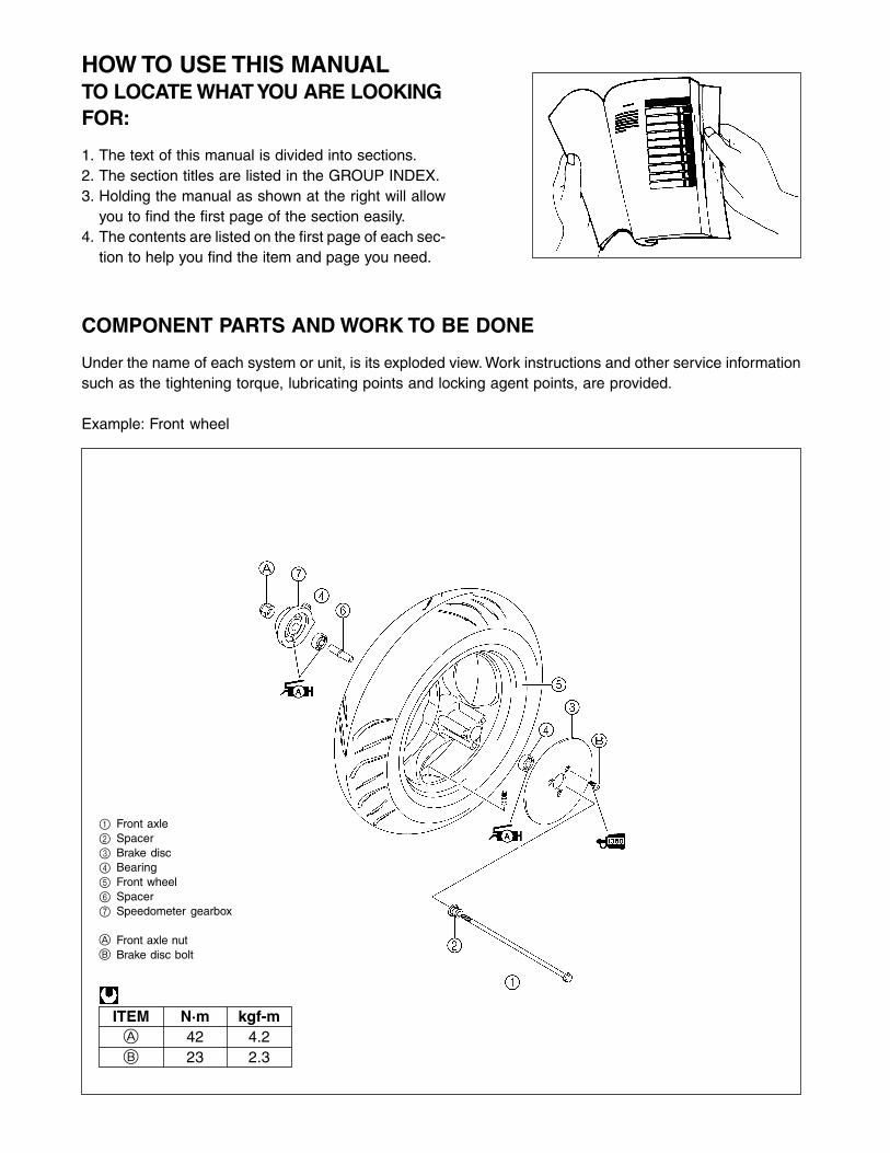
HOW TO USE THIS MANUALTO LOCATE WHAT YOU ARE LOOKINGFOR:
1. The text of this manual is divided into sections.2. The section titles are listed in the GROUP INDEX.3. Holding the manual as shown at the right will allow
you to find the first page of the section easily.4. The contents are listed on the first page of each sec-
tion to help you find the item and page you need.
COMPONENT PARTS AND WORK TO BE DONE
Under the name of each system or unit, is its exploded view. Work instructions and other service informationsuch as the tightening torque, lubricating points and locking agent points, are provided.
Example: Front wheel
1 Front axle2 Spacer3 Brake disc4 Bearing5 Front wheel6 Spacer7 Speedometer gearbox
A Front axle nutB Brake disc bolt
ITEM N·m kgf-mA 42 4.2B 23 2.3

SYMBOL
Listed in the table below are the symbols indicating instructions and other information necessary for servic-ing. The meaning of each symbol is also included in the table.
SYMBOL DEFINITION
Torque control required.Data beside it indicates specified torque.
Indicates service data.
Apply oil. Use engine oil unless other-wise specified.
Apply SUZUKI SUPER GREASE “A”.
99000-25010
Apply SUZUKI MOLY PASTE.
99000-25140
Apply THREAD LOCK “1342”.
99000-32050
Apply THREAD LOCK SUPER “1322”.
99000-32110
Apply THREAD LOCK SUPER “1360”.
99000-32130
SYMBOL DEFINITION
Apply or use brake fluid.
Measure in voltage range.
Measure in resistance range.
Measure in current range.
Measure in diode test range.
Measure in continuity test range.
Use special tool.

GENERAL INFORMATION 1-1
GENERAL INFORMATION
CONTENTS
WARNING/CAUTION/NOTE............................................................................ 1- 2GENERAL PRECAUTIONS ............................................................................ 1- 2SUZUKI UF50Y/UF50ZY (2000-MODEL) ....................................................... 1- 4SERIAL NUMBER LOCATION ....................................................................... 1- 4FUEL AND OIL RECOMMENDATIONS ......................................................... 1- 4
FUEL............................................................................................................ 1- 4ENGINE OIL ................................................................................................ 1- 4FINAL GEAR OIL ........................................................................................ 1- 5BRAKE FLUID ............................................................................................ 1- 5
BREAK-IN PROCEDURES ............................................................................. 1- 5INFORMATION LABELS................................................................................. 1- 6SPECIFICATIONS ........................................................................................... 1- 7
1

1-2 GENERAL INFORMATION
WARNING/CAUTION/NOTE
Please read this manual and follow its instructions carefully. To emphasize special information, the symboland the words WARNING, CAUTION and NOTE have special meanings. Pay special attention to the mes-sages highlighted by these signal words.
Indicates a potential hazard that could result in death or injury.
Indicates a potential hazard that could result in motorcycle damage.
NOTE:Indicates special information to make maintenance easier or instructions clearer.
Please note, however, that the warnings and cautions contained in this manual cannot possibly cover allpotential hazards relating to the servicing, or lack of servicing, of the motorcycle. In addition to the WARN-INGS and CAUTIONS stated, you must use good judgement and basic mechanical safety principles. If youare unsure about how to perform a particular service operation, ask a more experienced mechanic foradvice.
GENERAL PRECAUTIONS
Proper service and repair procedures are important for the safety of the service mechanicand the safety and reliability of the motorcycle.When two or more persons work together, pay attention to the safety of each other.When it is necessary to run the engine indoors, make sure that exhaust gas is forced out-doors.When working with toxic or flammable materials, make sure that the area you work in is wellventilated and that you follow all of the manufacturer’s instructions.Never use gasoline as a cleaning solvent.To avoid getting burned, do not touch the engine, engine oil, and exhaust system until theyhave cooled.After servicing the fuel, oil, exhaust or brake systems, check all of the lines, and fittingsrelated to the system for leaks.

GENERAL INFORMATION 1-3
If parts replacement is necessary, replace the parts with SUZUKI Genuine Parts or their equiva-lent.When removing parts that are to be reused, keep them arranged in an orderly manner so thatthey may be reinstalled in the proper order.Be sure to use special tools when instructed.Make sure that all parts used in reassembly are clean. Lubricate them when specified.Use the specified lubricants, bonds, or sealants.When removing the battery, disconnect the ----- battery lead wire first, then the +++++ battery leadwire.When reconnecting the battery, connect the +++++ battery lead wire first, then the ----- battery leadwire. Finally, cover the +++++ battery terminal with the terminal cover.When performing service to electrical parts, disconnect the ----- battery lead wire, unless theservice procedure requires the battery power.When tightening cylinder head and crankcase nuts and bolts, tighten the larger sizes first.Always tighten the nuts and bolts from the inside working out, diagonally and to the specifiedtorque.Whenever you remove oil seals, gaskets, packing, O-rings, self-locking nuts, locking wash-ers, cotter pins, circlips, and other specified parts, be sure to replace them with new ones.Also, before installing these new parts, be sure to remove any left over material from themating surfaces.Never reuse a circlip. When installing a new circlip, take care not to expand the end gap largerthan required to slip the circlip over the shaft. After installing a circlip, always ensure it iscompletely seated in its groove and securely fitted.Use a torque wrench to tighten fasteners to the specified torque. Wipe off grease and oil if athread is smeared with them.After reassembling, check parts for tightness and proper operation.
To protect the environment, do not unlawfully dispose of used motor oil, all other fluids,batteries, and tires.To protect the earth’s natural resources, properly dispose of used motorcycles and parts.

1-4 GENERAL INFORMATION
SUZUKI UF50Y/UF50ZY (2000-MODEL)
FUEL AND OIL RECOMMENDATIONS
Be sure to use the specified fuel and oils. Fuel and oil specifica-tions are listed below.
FUEL
Use unleaded gasoline that is graded 91 octane or higher ratedby the Research Method.
3 Fuel tank cap
ENGINE OIL
Use SUZUKI CCI SUPER OIL or an equivalent premium quality2-stroke synthetic engine oil. Use only oils which are rated FCunder the JASO classification.
4 Engine oil tank cap
* Difference between photographs and the actual motorcycles depends on the markets.
SERIAL NUMBER LOCATION
The frame serial number or V.I.N. (Vehicle Identification Number) 1 is stamped on the right side of thesteering head pipe. The engine serial number 2 is located on the end of the crankcase. These numbers arerequired especially for registering the machine and ordering spare parts.
RIGHT SIDE LEFT SIDE
12
34

GENERAL INFORMATION 1-5
FINAL GEAR OIL
Use a good quality SAE 10W-40 multigrade motor oil.
BRAKE FLUID
Specification and classification: DOT 4
This motorcycle uses a glycol-based brake fluid. Do not use or mix other types of brake fluidsuch as silicone-based and petroleum-based fluids for refilling the system, otherwise seri-ous damage will result to the brake system.Do not use any brake fluid taken from old, used, or unsealed containers.Do not reuse brake fluid left over from the last servicing or which has been stored for a longperiod of time.
BREAK-IN PROCEDURES
During manufacturing only the best possible materials are used and all machined parts are finished to avery high standard. It is still necessary to allow the moving parts to “BREAK-IN” before subjecting the engineto maximum stresses. The future performance and reliability of the engine depends on the care and restraintexercised during its early life. Refer to the following break-in engine speed recommendations.
Keep to these break-in throttle positions during the break-in period.
Break-in throttle positionInitial 800 km: Less than 1/2 throttleUp to 1 600 km: Less than 3/4 throttle
Upon reaching an odometer reading of 1 600 km you can subject the motorcycle to full throttle operation,for short periods of time.

1-6 GENERAL INFORMATION
INFORMATION LABELS
Battery caution label
Engine startinglabel
Tire information label
Loading cap label
General warning label
GENERAL INFORMATION 1-7
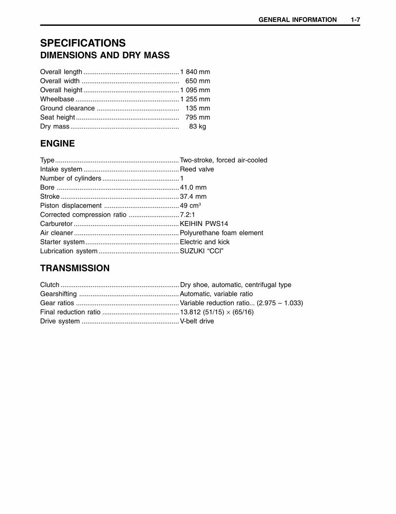
SPECIFICATIONSDIMENSIONS AND DRY MASS
Overall length ................................................... 1 840 mmOverall width .................................................... 650 mmOverall height ................................................... 1 095 mmWheelbase ....................................................... 1 255 mmGround clearance ............................................ 135 mmSeat height ....................................................... 795 mmDry mass .......................................................... 83 kg
ENGINE
Type..................................................................Two-stroke, forced air-cooledIntake system ...................................................Reed valveNumber of cylinders ......................................... 1Bore .................................................................41.0 mmStroke ............................................................... 37.4 mmPiston displacement ........................................ 49 cm3
Corrected compression ratio ........................... 7.2:1Carburetor ........................................................KEIHIN PWS14Air cleaner ........................................................Polyurethane foam elementStarter system..................................................Electric and kickLubrication system ...........................................SUZUKI “CCI”
TRANSMISSION
Clutch ...............................................................Dry shoe, automatic, centrifugal typeGearshifting .....................................................Automatic, variable ratioGear ratios .......................................................Variable reduction ratio... (2.975 – 1.033)Final reduction ratio ......................................... 13.812 (51/15) × (65/16)Drive system ....................................................V-belt drive
1-8 GENERAL INFORMATION
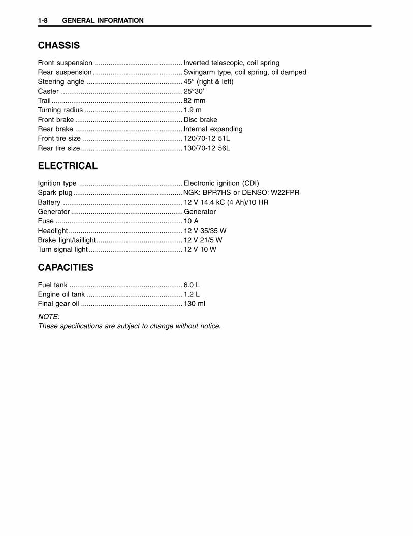
CHASSIS
Front suspension ............................................. Inverted telescopic, coil springRear suspension ..............................................Swingarm type, coil spring, oil dampedSteering angle ................................................. 45° (right & left)Caster .............................................................. 25°30’Trail ................................................................... 82 mmTurning radius .................................................. 1.9 mFront brake .......................................................Disc brakeRear brake ....................................................... Internal expandingFront tire size ................................................... 120/70-12 51LRear tire size .................................................... 130/70-12 56L
ELECTRICAL
Ignition type .....................................................Electronic ignition (CDI)Spark plug ........................................................NGK: BPR7HS or DENSO: W22FPRBattery ............................................................. 12 V 14.4 kC (4 Ah)/10 HRGenerator .........................................................GeneratorFuse ................................................................. 10 AHeadlight .......................................................... 12 V 35/35 WBrake light/taillight ............................................ 12 V 21/5 WTurn signal light ................................................ 12 V 10 W
CAPACITIES
Fuel tank .......................................................... 6.0 LEngine oil tank ................................................. 1.2 LFinal gear oil .................................................... 130 ml
NOTE:These specifications are subject to change without notice.
PERIODIC MAINTENANCE 2-1
PERIODIC MAINTENANCE
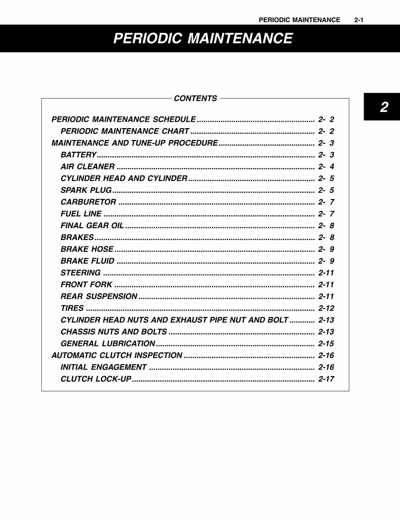
CONTENTS
PERIODIC MAINTENANCE SCHEDULE ....................................................... 2- 2PERIODIC MAINTENANCE CHART .......................................................... 2- 2
MAINTENANCE AND TUNE-UP PROCEDURE............................................. 2- 3BATTERY..................................................................................................... 2- 3AIR CLEANER ............................................................................................ 2- 4CYLINDER HEAD AND CYLINDER ........................................................... 2- 5SPARK PLUG.............................................................................................. 2- 5CARBURETOR ........................................................................................... 2- 7FUEL LINE .................................................................................................. 2- 7FINAL GEAR OIL ........................................................................................ 2- 8BRAKES ...................................................................................................... 2- 8BRAKE HOSE ............................................................................................. 2- 9BRAKE FLUID ............................................................................................ 2- 9STEERING .................................................................................................. 2-11FRONT FORK ............................................................................................. 2-11REAR SUSPENSION .................................................................................. 2-11TIRES .......................................................................................................... 2-12CYLINDER HEAD NUTS AND EXHAUST PIPE NUT AND BOLT ............ 2-13CHASSIS NUTS AND BOLTS .................................................................... 2-13GENERAL LUBRICATION.......................................................................... 2-15
AUTOMATIC CLUTCH INSPECTION ............................................................. 2-16INITIAL ENGAGEMENT ............................................................................. 2-16CLUTCH LOCK-UP..................................................................................... 2-17
2
2-2 PERIODIC MAINTENANCE
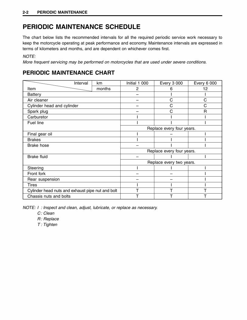
PERIODIC MAINTENANCE SCHEDULE
The chart below lists the recommended intervals for all the required periodic service work necessary tokeep the motorcycle operating at peak performance and economy. Maintenance intervals are expressed interms of kilometers and months, and are dependent on whichever comes first.
NOTE:More frequent servicing may be performed on motorcycles that are used under severe conditions.
PERIODIC MAINTENANCE CHART
Interval km Initial 1 000 Every 3 000 Every 6 000Item months 2 6 12Battery – I IAir cleaner – C CCylinder head and cylinder – C CSpark plug – C RCarburetor I I IFuel line I I I
Replace every four years.Final gear oil I – IBrakes I I IBrake hose – I I
Replace every four years.Brake fluid – I I
Replace every two years.Steering I I IFront fork – – IRear suspension – – ITires I I ICylinder head nuts and exhaust pipe nut and bolt T T TChassis nuts and bolts T T T
NOTE: I : Inspect and clean, adjust, lubricate, or replace as necessary.C : CleanR: ReplaceT : Tighten
PERIODIC MAINTENANCE 2-3
MAINTENANCE AND TUNE-UPPROCEDURE
This section describes the servicing procedures for each itemmentioned in the periodic maintenance chart on the previouspage.
BATTERY
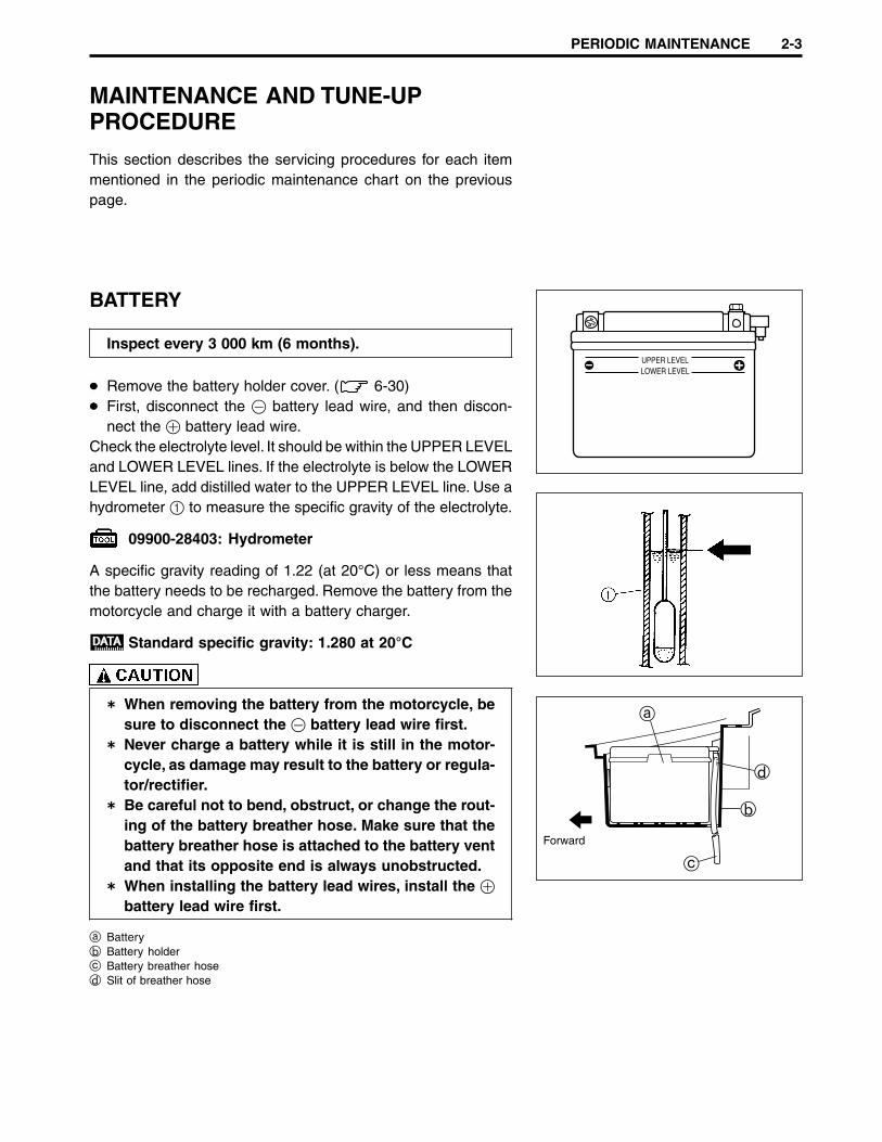
Inspect every 3 000 km (6 months).
Remove the battery holder cover. ( 6-30)First, disconnect the - battery lead wire, and then discon-nect the + battery lead wire.
Check the electrolyte level. It should be within the UPPER LEVELand LOWER LEVEL lines. If the electrolyte is below the LOWERLEVEL line, add distilled water to the UPPER LEVEL line. Use ahydrometer 1 to measure the specific gravity of the electrolyte.
09900-28403: Hydrometer
A specific gravity reading of 1.22 (at 20°C) or less means thatthe battery needs to be recharged. Remove the battery from themotorcycle and charge it with a battery charger.
Standard specific gravity: 1.280 at 20°C
When removing the battery from the motorcycle, besure to disconnect the - battery lead wire first.Never charge a battery while it is still in the motor-cycle, as damage may result to the battery or regula-tor/rectifier.Be careful not to bend, obstruct, or change the rout-ing of the battery breather hose. Make sure that thebattery breather hose is attached to the battery ventand that its opposite end is always unobstructed.When installing the battery lead wires, install the +battery lead wire first.
a Batteryb Battery holderc Battery breather hosed Slit of breather hose
UPPER LEVELLOWER LEVEL
a
b
c
d
Forward
2-4 PERIODIC MAINTENANCE
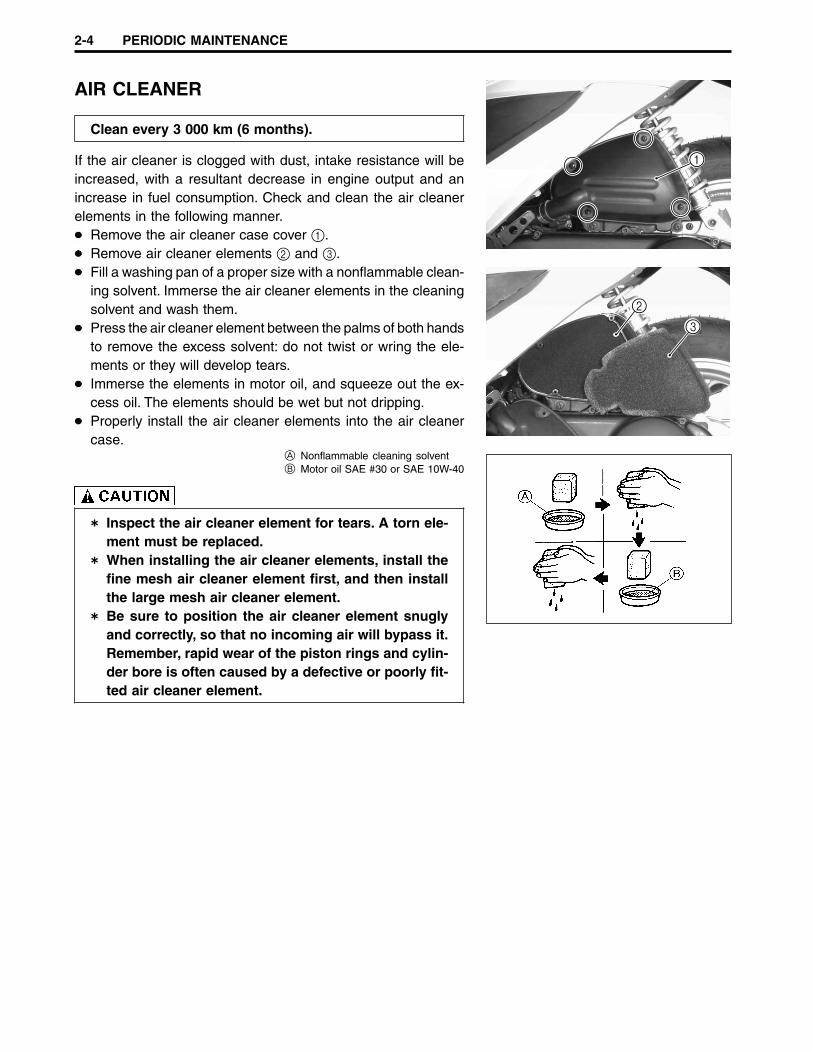
AIR CLEANER
Clean every 3 000 km (6 months).
If the air cleaner is clogged with dust, intake resistance will beincreased, with a resultant decrease in engine output and anincrease in fuel consumption. Check and clean the air cleanerelements in the following manner.
Remove the air cleaner case cover 1.Remove air cleaner elements 2 and 3.Fill a washing pan of a proper size with a nonflammable clean-ing solvent. Immerse the air cleaner elements in the cleaningsolvent and wash them.Press the air cleaner element between the palms of both handsto remove the excess solvent: do not twist or wring the ele-ments or they will develop tears.Immerse the elements in motor oil, and squeeze out the ex-cess oil. The elements should be wet but not dripping.Properly install the air cleaner elements into the air cleanercase.
A Nonflammable cleaning solventB Motor oil SAE #30 or SAE 10W-40
Inspect the air cleaner element for tears. A torn ele-ment must be replaced.When installing the air cleaner elements, install thefine mesh air cleaner element first, and then installthe large mesh air cleaner element.Be sure to position the air cleaner element snuglyand correctly, so that no incoming air will bypass it.Remember, rapid wear of the piston rings and cylin-der bore is often caused by a defective or poorly fit-ted air cleaner element.
1
2
3

PERIODIC MAINTENANCE 2-5
CYLINDER HEAD AND CYLINDER
Remove carbon every 3 000 km (6 months).
( 3-13)
SPARK PLUG
Clean every 3 000 km (6 months).Replace every 6 000 km (12 months).
Remove the left side leg shield. ( 5-3)Disconnect the spark plug cap and remove the spark plug.
NGK DENSOStandard BPR7HS W22FPR
CARBON DEPOSITCheck for carbon deposits on the spark plug. If any carbon isdeposited on the spark plug, remove it using a spark plug cleanermachine or carefully use a tool with a pointed end.

2-6 PERIODIC MAINTENANCE
SPARK PLUG GAPMeasure the spark plug gap using a thickness gauge. If the sparkplug gap is out of specification, adjust the gap.
Spark plug gapStandard: 0.6 – 0.7 mm
09900-20804: Thickness gauge
ELECTRODESCheck the condition of the electrodes.If the electrode is extremely worn or burnt, replace the sparkplug with a new one.Also, replace the spark plug if it has a broken insulator, dam-aged threads, etc.
Check the tread size and reach when replacing thespark plug. If the reach is too short, carbon will be de-posited on the screw portion of the spark plug holeand engine damage may result.
SPARK PLUG INSTALLATION
To avoid damaging the cylinder head threads; first, fin-ger tighten the spark plug, and then tighten it to thespecified torque using the spark plug wrench.
Insert the spark plug and finger tighten it to the cylinder headand then tighten it to the specified torque.
Spark plug: 28 N·m (2.8 kgf-m)
0.6 – 0.7 mm
PERIODIC MAINTENANCE 2-7
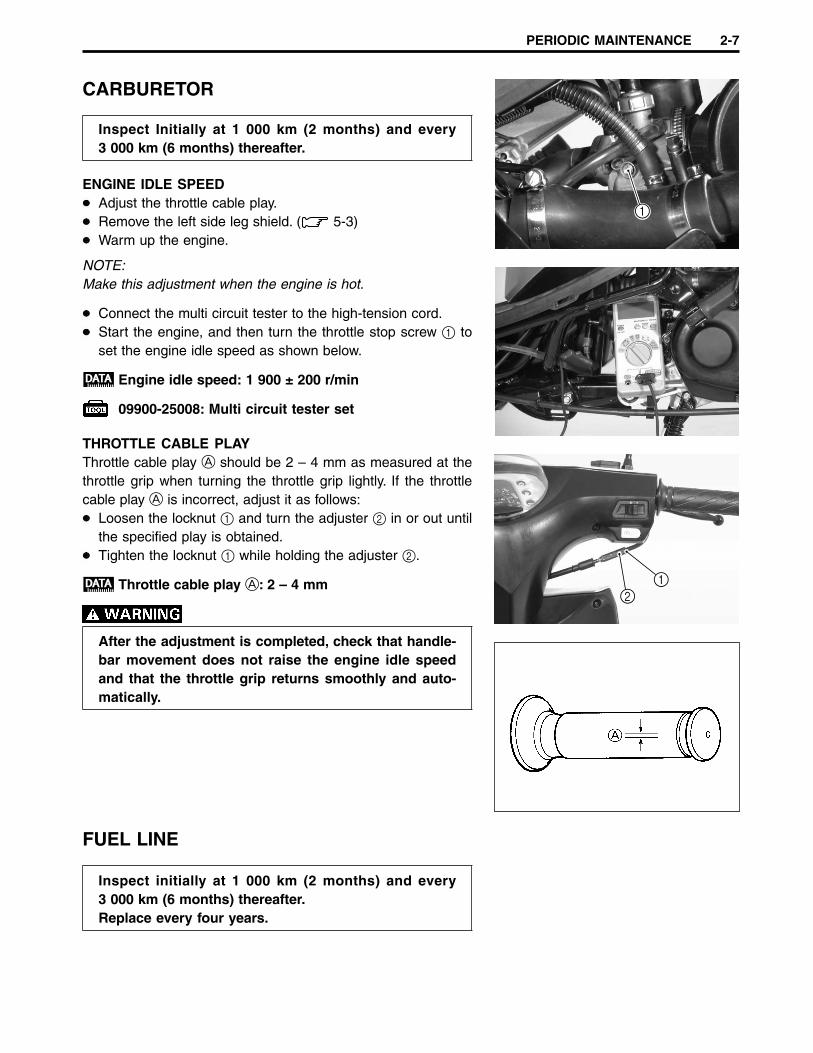
CARBURETOR
Inspect Initially at 1 000 km (2 months) and every3 000 km (6 months) thereafter.
ENGINE IDLE SPEEDAdjust the throttle cable play.Remove the left side leg shield. ( 5-3)Warm up the engine.
NOTE:Make this adjustment when the engine is hot.
Connect the multi circuit tester to the high-tension cord.Start the engine, and then turn the throttle stop screw 1 toset the engine idle speed as shown below.
Engine idle speed: 1 900 ± 200 r/min
09900-25008: Multi circuit tester set
THROTTLE CABLE PLAYThrottle cable play A should be 2 – 4 mm as measured at thethrottle grip when turning the throttle grip lightly. If the throttlecable play A is incorrect, adjust it as follows:
Loosen the locknut 1 and turn the adjuster 2 in or out untilthe specified play is obtained.Tighten the locknut 1 while holding the adjuster 2.
Throttle cable play A: 2 – 4 mm
After the adjustment is completed, check that handle-bar movement does not raise the engine idle speedand that the throttle grip returns smoothly and auto-matically.
FUEL LINE
Inspect initially at 1 000 km (2 months) and every3 000 km (6 months) thereafter.Replace every four years.
1
21
2-8 PERIODIC MAINTENANCE
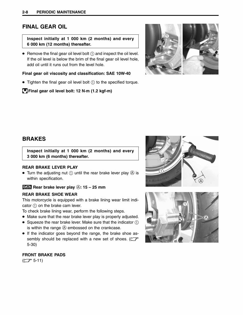
FINAL GEAR OIL
Inspect initially at 1 000 km (2 months) and every6 000 km (12 months) thereafter.
Remove the final gear oil level bolt 1 and inspect the oil level.If the oil level is below the brim of the final gear oil level hole,add oil until it runs out from the level hole.
Final gear oil viscosity and classification: SAE 10W-40
Tighten the final gear oil level bolt 1 to the specified torque.
Final gear oil level bolt: 12 N·m (1.2 kgf-m)
BRAKES
Inspect initially at 1 000 km (2 months) and every3 000 km (6 months) thereafter.
REAR BRAKE LEVER PLAYTurn the adjusting nut 1 until the rear brake lever play A iswithin specification.
Rear brake lever play A: 15 – 25 mm
REAR BRAKE SHOE WEARThis motorcycle is equipped with a brake lining wear limit indi-cator 1 on the brake cam lever.To check brake lining wear, perform the following steps.
Make sure that the rear brake lever play is properly adjusted.Squeeze the rear brake lever. Make sure that the indicator 1is within the range A embossed on the crankcase.If the indicator goes beyond the range, the brake shoe as-sembly should be replaced with a new set of shoes. (5-30)
FRONT BRAKE PADS( 5-11)
1
1
A
A
1

PERIODIC MAINTENANCE 2-9
BRAKE HOSE
Inspect every 3 000 km (6 months).Replace every four years.
Check the brake hose for leakage, cracks, wear, and damages.If any damages are found, replace the brake hose with a newone.
BRAKE FLUID
Inspect every 3 000 km (6 months).Replace fluid every two years.
FRONT BRAKE FLUID LEVELKeep the motorcycle upright and place the handlebars straight.Check the brake fluid level by observing the lower limit line onthe brake fluid reservoir.When the brake fluid level is below the lower limit line, replen-ish with a brake fluid that meets the following specification.
NOTE:If the brake fluid level is difficult to check, remove the mastercylinder reservoir cap to check the brake fluid level.
Specification and classification: DOT 4
The brake system is filled with an glycol-based brakefluid, which is classified DOT 4. Do not use or mixother types of brake fluid, such as silicone-basedand petroleum-based brake fluids when refilling thebrake system, otherwise serious damage to the brakesystem will result.Do not use any brake fluid taken from old, used, orunsealed containers.Do not reuse brake fluid left over from the last servic-ing or which has been stored for a long period of time.When storing brake fluid, be sure to seal the con-tainer completely and keep it out of the reach of chil-dren.When replenishing brake fluid, be sure not to getany dust or other foreign materials in the fluid.Brake fluid, if it leaks, will interfere with safe runningand immediately discolor painted surfaces. Checkthe brake hoses and hose joints for cracks and oilleakage before riding.
2-10 PERIODIC MAINTENANCE
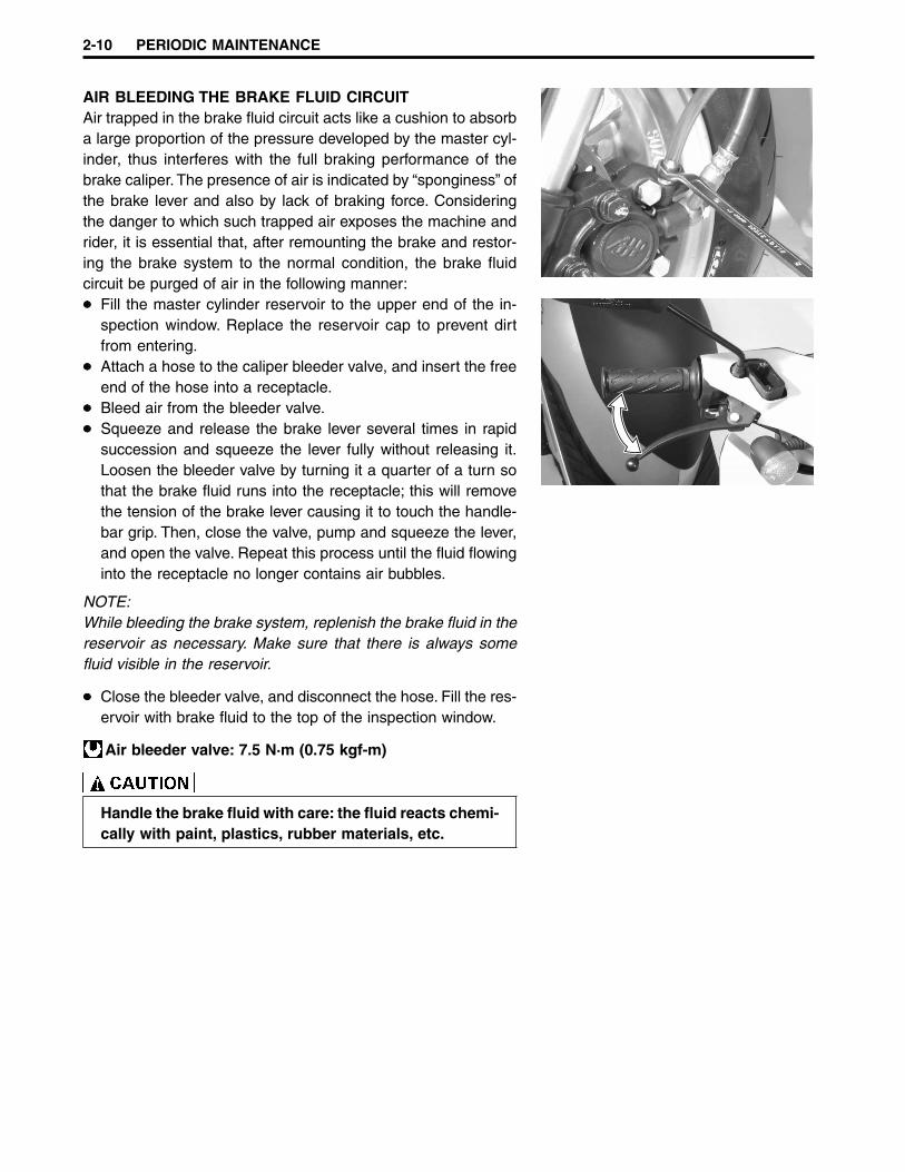
AIR BLEEDING THE BRAKE FLUID CIRCUITAir trapped in the brake fluid circuit acts like a cushion to absorba large proportion of the pressure developed by the master cyl-inder, thus interferes with the full braking performance of thebrake caliper. The presence of air is indicated by “sponginess” ofthe brake lever and also by lack of braking force. Consideringthe danger to which such trapped air exposes the machine andrider, it is essential that, after remounting the brake and restor-ing the brake system to the normal condition, the brake fluidcircuit be purged of air in the following manner:
Fill the master cylinder reservoir to the upper end of the in-spection window. Replace the reservoir cap to prevent dirtfrom entering.Attach a hose to the caliper bleeder valve, and insert the freeend of the hose into a receptacle.Bleed air from the bleeder valve.Squeeze and release the brake lever several times in rapidsuccession and squeeze the lever fully without releasing it.Loosen the bleeder valve by turning it a quarter of a turn sothat the brake fluid runs into the receptacle; this will removethe tension of the brake lever causing it to touch the handle-bar grip. Then, close the valve, pump and squeeze the lever,and open the valve. Repeat this process until the fluid flowinginto the receptacle no longer contains air bubbles.
NOTE:While bleeding the brake system, replenish the brake fluid in thereservoir as necessary. Make sure that there is always somefluid visible in the reservoir.
Close the bleeder valve, and disconnect the hose. Fill the res-ervoir with brake fluid to the top of the inspection window.
Air bleeder valve: 7.5 N·m (0.75 kgf-m)
Handle the brake fluid with care: the fluid reacts chemi-cally with paint, plastics, rubber materials, etc.
PERIODIC MAINTENANCE 2-11
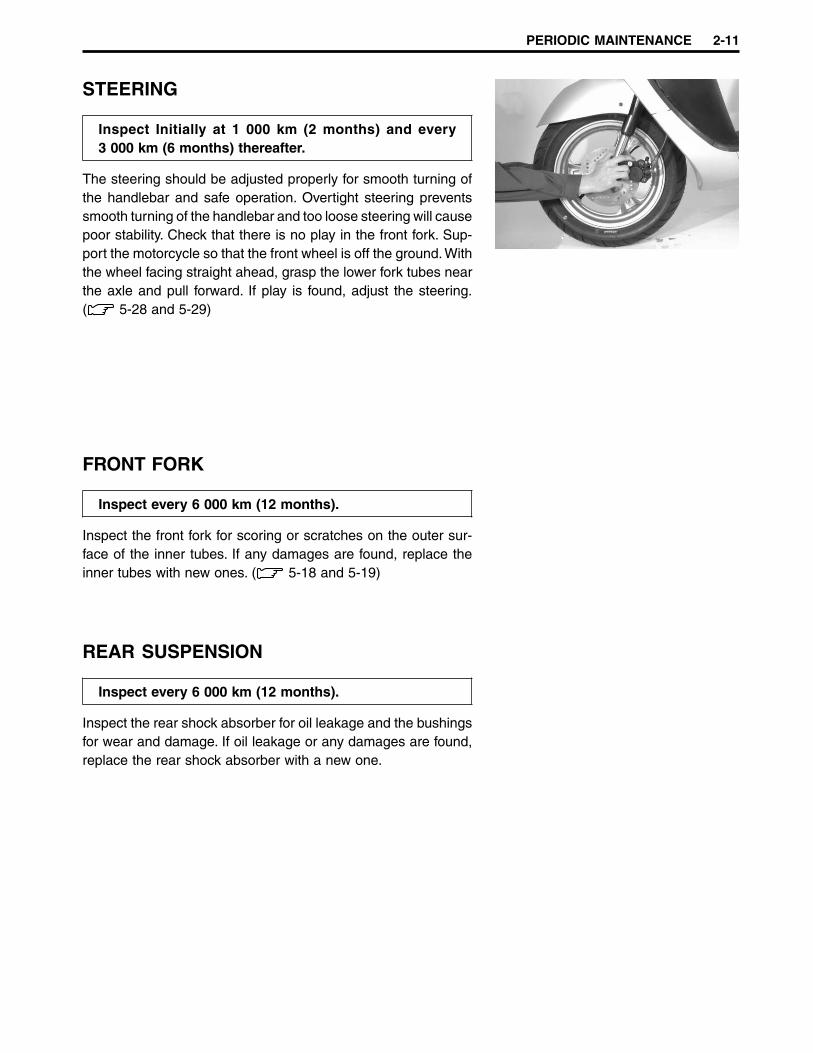
STEERING
Inspect Initially at 1 000 km (2 months) and every3 000 km (6 months) thereafter.
The steering should be adjusted properly for smooth turning ofthe handlebar and safe operation. Overtight steering preventssmooth turning of the handlebar and too loose steering will causepoor stability. Check that there is no play in the front fork. Sup-port the motorcycle so that the front wheel is off the ground. Withthe wheel facing straight ahead, grasp the lower fork tubes nearthe axle and pull forward. If play is found, adjust the steering.( 5-28 and 5-29)
FRONT FORK
Inspect every 6 000 km (12 months).
Inspect the front fork for scoring or scratches on the outer sur-face of the inner tubes. If any damages are found, replace theinner tubes with new ones. ( 5-18 and 5-19)
REAR SUSPENSION
Inspect every 6 000 km (12 months).
Inspect the rear shock absorber for oil leakage and the bushingsfor wear and damage. If oil leakage or any damages are found,replace the rear shock absorber with a new one.

2-12 PERIODIC MAINTENANCE
TIRES
Inspect initially at 1 000 km (2 months) and every3 000 km (6 months) thereafter.
TIRE TREAD CONDITIONOperating the motorcycle with excessively worn tires will de-crease riding stability and consequently invite a dangerous situ-ation. It is highly recommended to replace a tire when the re-maining depth of the tire tread reaches the following specifica-tion.
Tire tread depth (front and rear)Service Limit: 1.6 mm
09900-20805: Tire depth gauge
TIRE PRESSUREIf the tire pressure is too high or too low, steering will be ad-versely affected and tire wear will increase. Therefore, maintainthe correct tire pressure for good roadability and a longer tirelife. Cold inflation tire pressure is as follows.
Cold inflation tire pressureSolo ridingFront: 125 kPa (1.25 kgf/cm2)Rear: 175 kPa (1.75 kgf/cm2)Dual riding (except for UF50Z)Front: 125 kPa (1.25 kgf/cm2)Rear: 230 kPa (2.30 kgf/cm2)
The standard tire fitted on this motorcycle is 120/70-1251L for the front and 130/70-12 56L for the rear. The useof tires other than those specified may cause instabil-ity. It is highly recommended to use the specified tires.
PERIODIC MAINTENANCE 2-13
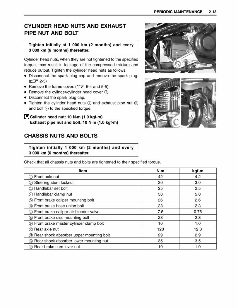
CYLINDER HEAD NUTS AND EXHAUSTPIPE NUT AND BOLT
Tighten initially at 1 000 km (2 months) and every3 000 km (6 months) thereafter.
Cylinder head nuts, when they are not tightened to the specifiedtorque, may result in leakage of the compressed mixture andreduce output. Tighten the cylinder head nuts as follows.
Disconnect the spark plug cap and remove the spark plug.( 2-5)Remove the frame cover. ( 5-4 and 5-5)Remove the cylinder/cylinder head cover 1.Disconnect the spark plug cap.Tighten the cylinder head nuts 2 and exhaust pipe nut 3
and bolt 4 to the specified torque.
Cylinder head nut: 10 N·m (1.0 kgf-m)Exhaust pipe nut and bolt: 10 N·m (1.0 kgf-m)
CHASSIS NUTS AND BOLTS
Tighten initially 1 000 km (2 months) and every3 000 km (6 months) thereafter.
Check that all chassis nuts and bolts are tightened to their specified torque.
Item N·m kgf-m1 Front axle nut 42 4.22 Steering stem locknut 30 3.03 Handlebar set bolt 25 2.54 Handlebar clamp nut 50 5.05 Front brake caliper mounting bolt 26 2.66 Front brake hose union bolt 23 2.37 Front brake caliper air bleeder valve 7.5 0.758 Front brake disc mounting bolt 23 2.39 Front brake master cylinder clamp bolt 10 1.00 Rear axle nut 120 12.0A Rear shock absorber upper mounting bolt 29 2.9B Rear shock absorber lower mounting nut 35 3.5C Rear brake cam lever nut 10 1.0
1
22
3 4

2-14 PERIODIC MAINTENANCE
1 2
3
4
5 6
7
8
6
9
0
A
B
C

PERIODIC MAINTENANCE 2-15
GENERAL LUBRICATION
Proper lubrication is important for smooth operation and long life of each working part of the motorcycle.Major lubrication points are indicated below.
1 Rear brake lever holder2 Center stand pivot and spring hook
3 Front brake lever holder4 Speedometer cable
NOTE:Before lubricating each part, remove any rust and wipe off any grease, oil, dirt, or grime.Lubricate exposed parts which are subject to rust, with a rust preventative spray, especially whenever themotorcycle has been operated under wet or rainy conditions.
1
2
3
4
2-16 PERIODIC MAINTENANCE
AUTOMATIC CLUTCH INSPECTION
The UF50/UF50Z is equipped with a centrifugal type automaticclutch and a variable ratio belt drive transmission.To insure proper performance and longevity of the clutch as-sembly it is essential that the clutch assembly engages smoothlyand gradually. Two inspection checks must be performed to thor-oughly check the operation of the drive train. Follow the proce-dures listed.
NOTE:Warm up the engine.
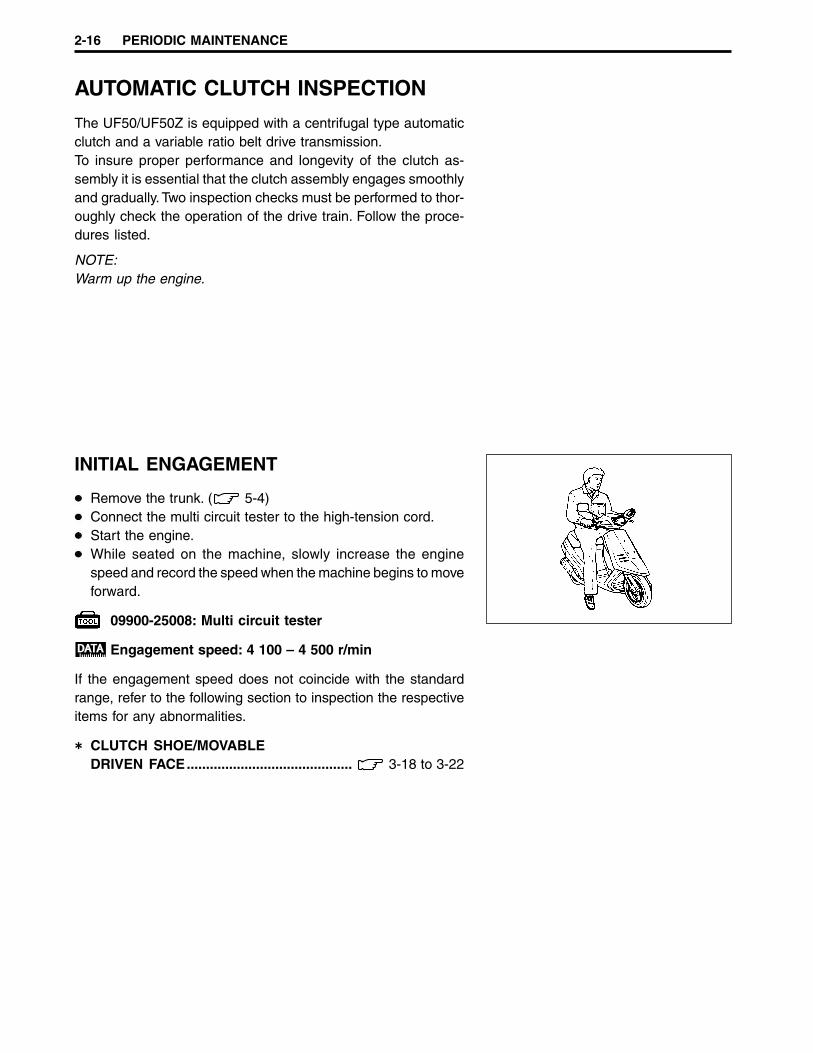
INITIAL ENGAGEMENT
Remove the trunk. ( 5-4)Connect the multi circuit tester to the high-tension cord.Start the engine.While seated on the machine, slowly increase the enginespeed and record the speed when the machine begins to moveforward.
09900-25008: Multi circuit tester
Engagement speed: 4 100 – 4 500 r/min
If the engagement speed does not coincide with the standardrange, refer to the following section to inspection the respectiveitems for any abnormalities.
CLUTCH SHOE/MOVABLEDRIVEN FACE........................................... 3-18 to 3-22

PERIODIC MAINTENANCE 2-17
CLUTCH LOCK-UP
Perform this inspection to determine if the clutch is engagingfully and not slipping.
Remove the trunk. ( 5-4)Connect the multi circuit tester to the high-tension cord.Start the engine.Apply the rear brake as firm as possible.Fully open the throttle for a brief period and note the maxi-mum engine speed sustained during the test cycle.
09900-25008: Multi circuit tester
Lock-up speed: 5 600 – 6 200 r/min
Do not apply full power for more than 10 seconds ordamage to the clutch assembly or engine may occur.
If the lock-up speed does not coincide with the standard range,refer to the following section to inspect the respective items forany abnormalities.
CLUTCH SHOE/MOVABLEDRIVEN FACE........................................... 3-18 to 3-22
ENGINE 3-1
ENGINE
3
CONTENTS
ENGINE COMPONENTS REMOVABLE WITH THEENGINE IN PLACE.......................................................................................... 3- 2ENGINE REMOVAL AND REMOUNTING ...................................................... 3- 3
ENGINE REMOVAL .................................................................................... 3- 3ENGINE REMOUNTING ............................................................................. 3- 5
ENGINE DISASSEMBLY................................................................................. 3- 6ENGINE COMPONENTS INSPECTION AND SERVICE ............................... 3-13
CYLINDER HEAD DISTORTION ................................................................ 3-13CYLINDER................................................................................................... 3-13PISTON ........................................................................................................ 3-14CRANKSHAFT AND CONROD .................................................................. 3-16REED VALVE ............................................................................................... 3-17CLUTCH SHOE/MOVABLE DRIVEN FACE ............................................... 3-18MOVABLE DRIVE FACE ............................................................................. 3-23KICK STARTER........................................................................................... 3-25BEARINGS .................................................................................................. 3-26OIL SEALS .................................................................................................. 3-28ENGINE MOUNTING BUSHINGS .............................................................. 3-31
ENGINE REASSEMBLY.................................................................................. 3-32CRANKSHAFT ............................................................................................ 3-32CRANKCASE .............................................................................................. 3-32REAR AXLE SHAFT AND TRANSMISSION.............................................. 3-34GENERATOR .............................................................................................. 3-36STARTER PINION AND STARTER GEAR ................................................. 3-37DRIVE BELT ................................................................................................ 3-38PISTON ........................................................................................................ 3-39CYLINDER................................................................................................... 3-40CYLINDER HEAD ....................................................................................... 3-40OIL PUMP GEAR ........................................................................................ 3-40INTAKE PIPE............................................................................................... 3-40EXHAUST PIPE/MUFFLER ........................................................................ 3-40
3-2 ENGINE
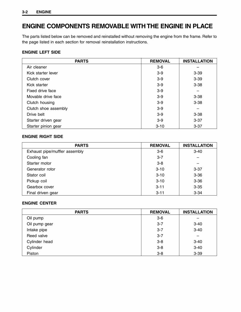
ENGINE COMPONENTS REMOVABLE WITH THE ENGINE IN PLACE
The parts listed below can be removed and reinstalled without removing the engine from the frame. Refer tothe page listed in each section for removal reinstallation instructions.
ENGINE LEFT SIDE
PARTS REMOVAL INSTALLATIONAir cleaner 3-6 –Kick starter lever 3-9 3-39Clutch cover 3-9 3-39Kick starter 3-9 3-38Fixed drive face 3-9 –Movable drive face 3-9 3-38Clutch housing 3-9 3-38Clutch shoe assembly 3-9 –Drive belt 3-9 3-38Starter driven gear 3-9 3-37Starter pinion gear 3-10 3-37
ENGINE RIGHT SIDE
PARTS REMOVAL INSTALLATIONExhaust pipe/muffler assembly 3-6 3-40Cooling fan 3-7 –Starter motor 3-8 –Generator rotor 3-10 3-37Stator coil 3-10 3-36Pickup coil 3-10 3-36Gearbox cover 3-11 3-35Final driven gear 3-11 3-34
ENGINE CENTER
PARTS REMOVAL INSTALLATIONOil pump 3-6 –Oil pump gear 3-7 3-40Intake pipe 3-7 3-40Reed valve 3-7 –Cylinder head 3-8 3-40Cylinder 3-8 3-40Piston 3-8 3-39

ENGINE 3-3
ENGINE REMOVAL ANDREMOUNTINGENGINE REMOVAL
Before taking the engine out of the frame, wash the engine witha steam cleaner. Engine removal is sequentially explained in thefollowing steps.
Remove the side leg shields and frame covers. ( 5-3 to5-5)Disconnect the - battery lead wire. ( 6-30)Disconnect the fuel hose 1, vacuum hose 2, oil hose 3,and carburetor heater lead wire 4.Remove the carburetor top cap 5 with the throttle cable andthrottle valve.
Disconnect the spark plug cap.
Disconnect the engine ground wire.
Disconnect the thermoelement coupler 6, starter motor cou-pler 7, and generator coupler 8.
4 5
1
3
2
6
7 8
3-4 ENGINE
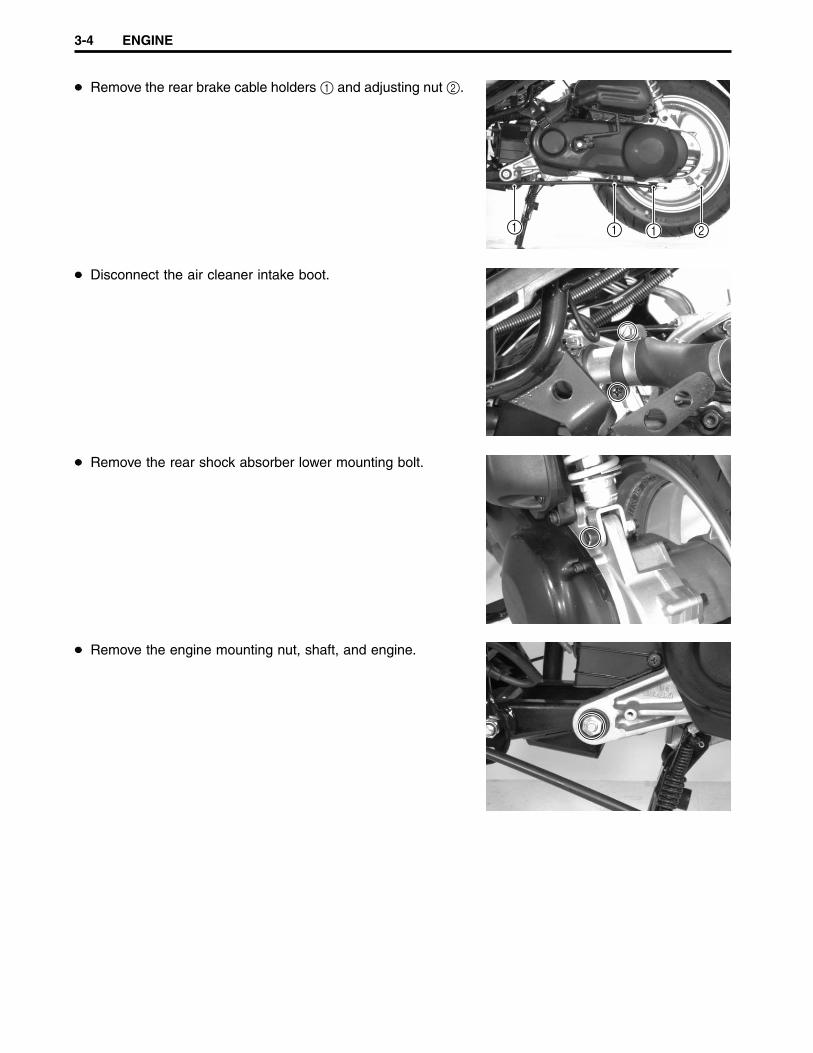
Remove the rear brake cable holders 1 and adjusting nut 2.
Disconnect the air cleaner intake boot.
Remove the rear shock absorber lower mounting bolt.
Remove the engine mounting nut, shaft, and engine.
1 1 1 2

ENGINE 3-5
ENGINE REMOUNTING
Remount the engine in the reverse order of removal. Pay atten-tion to the following points:
Install the crankcase bracket 1 to the frame and insert thecrankcase bracket mounting shaft.Push down on the rear part of the crankcase bracket and havethe damper 2 touch the stopper 3. While holding the damper,tighten the engine mounting bracket nut 4 to the specifiedtorque.
Engine mounting bracket nut: 65 N·m (6.5 kgf-m)
Install the engine and tighten the engine mounting nut 5 tothe specified torque.
Engine mounting nut: 60 N·m (6.0 kgf-m)
NOTE:When tightening the engine mounting nut, make sure that thefront wheel is elevated.
Tighten the rear shock absorber lower mounting nut 6 to thespecified torque.
Rear shock absorber nut: 35 N·m (3.5 kgf-m)
Place 65 kg on the seat, after installing the engine.Check that clearances A and B are equal. If clearances Aand B are not equal, repeat the engine installation proce-dures.After installing the engine, properly route the wire harness,cables, and hoses. Refer to the wire and cable routing sec-tions. ( 7-10 to 7-16)Refer to the following sections to adjust the respective itemsto specification.
THROTTLE CABLE PLAY ....................................... 2-7ENGINE IDLE SPEED ............................................. 2-7REAR BRAKE CABLE ADJUSTMENT ................. 2-8OIL PUMP AIR BLEEDING .................................. 4-13

3-6 ENGINE
ENGINE DISASSEMBLY
Remove the air cleaner.
Remove the exhaust pipe/muffler assembly.
Disconnect the oil hoses and remove the oil pump.
ENGINE 3-7
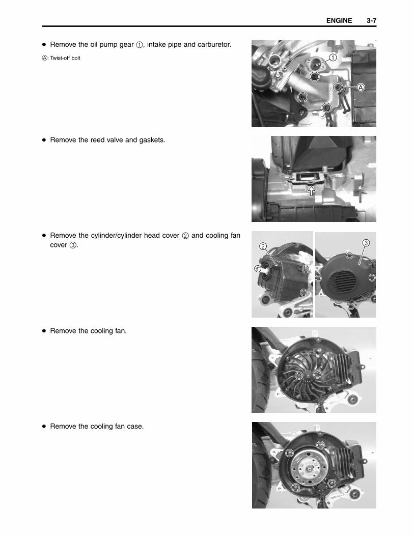
Remove the oil pump gear 1, intake pipe and carburetor.
A: Twist-off bolt
Remove the reed valve and gaskets.
Remove the cylinder/cylinder head cover 2 and cooling fancover 3.
Remove the cooling fan.
Remove the cooling fan case.
1
A
2 3

3-8 ENGINE
Remove the rear fender.
Loosen the cylinder head nuts diagonally, as shown, and thenremove them.Remove the cylinder head and gasket.
Remove the cylinder and gasket.
Place a clean rag over the cylinder base to prevent the pistonpin circlip from dropping into the crankcase. Then, removethe piston pin circlip with long-nose pliers.Remove the piston pin and piston.
Remove the starter motor.

ENGINE 3-9
Remove the kick starter lever 1, clutch cover 2, gaskets,and dowel pins.
Hold the generator rotor using the special tool and then re-move the kick starter nut.
09930-40113: Rotor holder
Remove the kick starter 3, fixed drive face 4, movable driveface 5, spacers, and washers.
Hold the clutch housing using the special tool and then re-move the clutch housing nut.
09930-40113: Rotor holder
Remove the clutch housing, clutch shoe assembly, and drivebelt.
Remove the starter driven gear.
2
1
35
4

3-10 ENGINE
Remove the starter pinion gear cap 1, starter pinion gearassembly 2, and dowel pins.
Drain the final gear oil.
Hold the generator rotor using the special tool and then re-move the generator rotor nut.
09930-40113: Rotor holder
Remove the generator rotor using the special tool.
09920-13120: Crankcase separating tool
Remove the stator coil 3, pickup coil 4, and key 5.3
5
4

ENGINE 3-11
Remove the rear wheel.
Remove the brake shoes.
Remove the brake cam lever 1, return spring 2, brake liningwear limit indicator 3, and brake camshaft 4.
Remove the gearbox cover.
Remove the final driven gear with the rear axle shaft 5, idleshaft/gear 6, and dowel pins 7.
3
4
21
75
6
7

3-12 ENGINE
Remove the driveshaft using the special tool.
09920-13120: Crankcase separating tool
Remove the center stand spring 1.Remove the cotter pin 2 and center stand shaft 3.Remove the center stand 4.
Remove the crankcase bolts.
Separate the left and right crankcases using the special tool.
09920-13120: Crankcase separating tool
Remove the gaskets and dowel pins.
Replace the removed gaskets with new ones.
Remove the crankshaft using the special tool.
09920-13120: Crankcase separating tool

ENGINE 3-13
ENGINE COMPONENTS INSPECTIONAND SERVICECYLINDER HEAD DISTORTION
Decarbonize the combustion chamber.Check the gasket surface of the cylinder head for distortion. Usea straightedge and thickness gauge. Take clearance readings atseveral places. If readings exceed the service limit, replace orflatten the cylinder head.
09900-20803: Thickness gauge
Cylinder head distortionService Limit: 0.05 mm
Place a sheet of emery paper (about #400 grit) on a surfaceplate. Use a figure-eight motion when grinding the cylinder headsurface.The gasket surface must be smooth and perfectly flat, for a tightfit. A leaky joint can cause reduced power and increased fuelconsumption.
CYLINDER
Remove carbon from the exhaust port and the upper part of thecylinder. Take care not to damage the surface of the cylinderwall.
CYLINDER BOREMeasure the cylinder bore with the cylinder gauge at 20 mmfrom the top of the cylinder.If the measurement exceeds the service limit, rebore the cylin-der and replace the piston with an oversized piston or replacethe cylinder with a new one. Oversized pistons are available intwo sizes: 0.5 mm and 1.0 mm.
09900-20508: Cylinder gauge set
Cylinder boreService Limit: 41.075 mm
Chamfer the port edges after reboring. Use a scraper and takecare not to nick the surface of the walls. Use emery paper (about#400 grit) to smooth the chamfered edges.
NOTE:Shallow grooves or minor scuffs can be removed by using em-ery paper (about #400 grit). If the flaws are deep grooves orcannot be removed with the emery paper, the cylinder must berebored to the next oversize.
1.0 – 1.5 mm
1.0 – 1.5 mm
0.3 – 0.5 mm
3-14 ENGINE
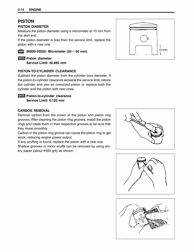
PISTONPISTON DIAMETERMeasure the piston diameter using a micrometer at 15 mm fromthe skirt end.If the piston diameter is less than the service limit, replace thepiston with a new one.
09900-20202: Micrometer (25 – 50 mm)
Piston diameterService Limit: 40.885 mm
PISTON-TO-CYLINDER CLEARANCESubtract the piston diameter from the cylinder bore diameter. Ifthe piston-to-cylinder clearance exceeds the service limit, reborethe cylinder and use an oversized piston or replace both thecylinder and the piston with new ones.
Piston-to-cylinder clearanceService Limit: 0.120 mm
CARBON REMOVALRemove carbon from the crown of the piston and piston ringgrooves. After cleaning the piston ring grooves, install the pistonrings and rotate them in their respective grooves to be sure thatthey move smoothly.Carbon in the piston ring groove can cause the piston ring to getstuck, reducing engine power output.If any scuffing is found, replace the piston with a new one.Shallow grooves or minor scuffs can be removed by using em-ery paper (about #400 grit) as shown.

ENGINE 3-15
PISTON PIN AND PIN BOREMeasure the piston pin bore inside diameter using the dial cali-pers and the piston pin outside diameter using the micrometer. Ifeither is out of specification or the difference between the mea-surements is more than their limits, replace the piston and pis-ton pin with new ones.
09900-20605: Dial calipers09900-20205: Micrometer (0 – 25 mm)
Piston pin bore I.D.Service Limit: 10.030 mm
Piston pin O.D.Service Limit: 9.980 mm
PISTON RING FREE END GAP AND PISTON RING END GAPMeasure the piston ring free end gap using vernier calipers. Then,fit the piston ring squarely into the cylinder and measure thepiston ring end gap using a thickness gauge.If any of the measurements exceed the service limit, replace thepiston ring with a new one.
09900-20101: Vernier calipers
Piston ring free end gapService Limit:1st: 3.2 mm ... R2nd: 3.4 mm ... R
09900-20803: Thickness gauge
Piston ring end gapService Limit: 0.80 mm
Measure the piston-ring-to-groove clearance using the thicknessgauge.If any of the clearances are out of specification, clean the grooveof the piston and piston rings.
09900-20803: Thickness gauge
Piston-ring-to-groove clearanceStandard:1st: 0.03 – 0.07 mm2nd: 0.02 – 0.06 mm

3-16 ENGINE
CRANKSHAFT AND CONROD
1 Oil seal (R)2 Bearing (R)3 Crankshaft (R)4 Crank pin5 Crank pin bearing6 Conrod7 Crankshaft (L)8 Spacer9 Piston pin bearing0 Bearing (L)A Oil seal (L)B Oil seal
CRANKSHAFT RUNOUTSupport the crankshaft using V-blocks as shown. Position thedial gauge, as shown, and rotate the crankshaft slowly to readthe runout. If the runout exceeds the service limit, correct therunout or replace the crankshaft assembly with a new one.
09900-20701: Magnetic stand09900-20606: Dial gauge (1/100 mm)09900-21304: V-block set (100 mm)
Crankshaft runoutService Limit: 0.05 mm

ENGINE 3-17
CONROD DEFLECTIONWear on the big end of the conrod can be estimated by checkingthe movement of the small end of the rod. This method can alsocheck the extent of wear on the parts of the big end of the conrod.
09900-20701: Magnetic stand09900-20606: Dial gauge (1/100 mm)09900-21304: V-block set (100 mm)
Conrod deflectionService Limit: 3.0 mm
If the service limit is exceeded, replace the crankshaft assemblyor bring the deflection into specification by replacing the wornparts (e.g., conrod, big end bearing and crank pin).
CONROD SMALL END I.D.Measure the conrod small end inside diameter using the dialcalipers. If the conrod small end inside diameter exceeds theservice limit, replace the conrod with a new one.
Conrod small end I.D.Service Limit: 14.040 mm
09900-20605: Dial calipers
REASSEMBLYWhen rebuilding the crankshaft, the width between the websshould be within the standard range.
Crank web to web widthStandard: 36.0 ± 0.05 mm
REED VALVE
Inspect the reed valve for wear or damage. If any damages arefound, replace the reed valve with a new one.

3-18 ENGINE
CLUTCH SHOE/MOVABLE DRIVEN FACE
1 Fixed driven face2 Bearing3 Circlip4 Needle roller bearing5 Movable driven face6 Oil seal7 Pin8 O-ring9 Movable driven face spring guide
ITEM N·m kgf-mA 50 5.0B 50 5.0
0 Oil sealA SpringB Clutch shoe assemblyC Clutch housingD Washer
A Clutch shoe nutB Clutch housing nut
DISASSEMBLYIf the engine speed does not coincide with the specified enginespeed range, disassemble the clutch shoe/movable driven faceas follows.
Hold the clutch shoe assembly using the special tools andthen loosen the clutch shoe nut.
09930-40113: Rotor holder09930-40131: Rotor holder attachment
Remove the clutch shoe nut 1 while holding down the clutchshoe assembly, as shown.
Gradually ease apart the clutch shoe assembly (tocounter the clutch spring force). Quickly releasing theclutch shoe assembly may cause the parts to fly apart.

ENGINE 3-19
Remove the clutch shoe assembly 1 and driven face spring 2.
Use a thin-blade screwdriver to pry up the movable drivenface spring guide.
Remove the pins 3, movable driven face 4, and fixed drivenface 5.
Remove the bearing using the special tools.
09923-73210: Bearing remover09930-30102: Sliding hammer
Replace the removed bearing with a new one.
Remove the circlip.

3-20 ENGINE
Remove the bearing using the special tool.
09941-50111: Bearing remover
Replace the removed bearing with a new one.
Remove the oil seals 1 and O-rings 2.
Replace the removed oil seals and O-rings with newones.
CLUTCH SHOEInspect the clutch shoe for chips, cracks, uneven wear and burn-ing. Check the thickness of the shoe using vernier calipers. Ifany damages are found or if the thickness is less than the ser-vice limit, replace the clutch shoe with a new one.
09900-20101: Vernier calipers
Clutch shoe thicknessService Limit: 2.0 mm
Inspect the clutch spring for stretched or broken coils. If any dam-ages are found, replace the clutch spring with a new one.
Replace the clutch shoe and clutch spring as a set.
Inspect the clutch housing surface for scrolling, cracks, or un-even wear and measure the inside diameter of the clutch hous-ing with inside calipers. Measure the diameter at several pointsto check for out-of-round and wear. If any damages are found orif the inside diameter exceeds the service limit, replace the clutchhousing with a new one.
Clutch housing I.D.Service Limit: 110.50 mm

ENGINE 3-21
DRIVEN FACE SPRINGMeasure the free length of the driven face spring. If the length isshorter than the service limit, replace the spring with a new one.
Driven face spring lengthService Limit: 104.5 mm
DRIVEN FACE PINS AND OIL SEALSRotate the driven faces and make sure that they turn smoothly.If they stick or do not turn smoothly, inspect the lip of each oilseal, and the sliding surface and sliding pins for wear or dam-age. If any damages are found, replace the driven face with anew one.
DRIVEN FACEInspect the drive belt contacting surface of both driven faces forany scratches, wear or damage. If any damages are found, re-place the driven faces with new ones.
REASSEMBLYReassemble the clutch shoe assembly and movable driven facein the reverse order of disassembly. Pay attention to the follow-ing points.
Install the bearing 2 in the fixed driven face 1 using the spe-cial tool.
09943-88211: Bearing installer
Securely install the circlip.

3-22 ENGINE
Install the needle roller bearing using the special tool.
09924-84521: Bearing installer
NOTE:Face the stamped side of the needle roller bearing out.
Apply SUZUKI SUPER GREASE “A” between the sliding sur-face of the fixed driven face and movable driven face.
99000-25010: SUZUKI SUPER GREASE “A”
NOTE:When installing the movable face to the fixed face, make surethat the oil seal is positioned properly.
Install the pins 1 at three places on the drive face hub.Apply sufficient SUZUKI SUPER GREASE “A” to the camwhere the pins are placed and to the surface of the drivenface, as shown.
99000-25010: SUZUKI SUPER GREASE “A”
Position the two O-rings 2.Install the movable driven face spring guide.
NOTE:Remove any grease from the movable driven face spring guide,after installation.
Hold the clutch shoe assembly using the special tools andthen tighten the clutch shoe nut to the specified torque.
09930-40113: Rotor holder09930-40131: Rotor holder attachment
Clutch shoe nut: 50 N·m (5.0 kgf-m)

ENGINE 3-23
MOVABLE DRIVE FACE
1 Movable drive face2 Roller3 Movable drive plate4 Damper5 Movable drive face cover6 Spacer7 Spacer8 Drive belt9 Fixed drive face0 WasherA Kick starterB Concave washer
A Kick starter nut
DISASSEMBLYRemove the movable drive face cover 1 and movable driveplate 2.
DRIVE FACEInspect the belt contact surface of the drive faces for wear,scratches or any abnormalities. If any damages are found, re-place the drive face with a new one.
1
2
ITEM N·m kgf-mA 50 5.0

3-24 ENGINE
ROLLER AND SLIDING SURFACEInspect each roller and its sliding surface for wear or damage. Ifany damages are found, replace the rollers as a set.
DRIVE BELTRemove the drive belt and check for cracks, wear and separa-tion and measure the drive belt width with vernier calipers. If anydamages are found or if the width of the drive belt is less thanthe service limit, replace the drive belt with a new one.
Drive belt widthService Limit: 17.4 mm
Always keep the drive belt away from grease, oil, etc.
REASSEMBLYMount the three dampers 1 on the movable drive plate 2and install it onto the movable drive face.
Install the movable drive face cover 3.
NOTE:Make sure that the movable drive plate is fully positioned insidethe movable drive face, otherwise the rollers may fall out.
Insert the spacer 4.
ENGINE 3-25
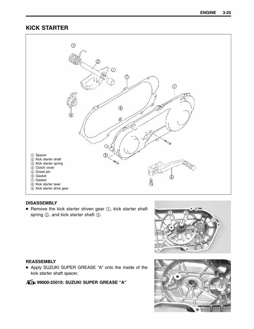
KICK STARTER
1 Spacer2 Kick starter shaft3 Kick starter spring4 Clutch cover5 Dowel pin6 Gasket7 Gasket8 Kick starter lever9 Kick starter drive gear
DISASSEMBLYRemove the kick starter driven gear 1, kick starter shaftspring 2, and kick starter shaft 3.
REASSEMBLYApply SUZUKI SUPER GREASE “A” onto the inside of thekick starter shaft spacer.
99000-25010: SUZUKI SUPER GREASE “A”
2 3
1
3-26 ENGINE
Apply a light coat of SUZUKI SUPER GREASE “A” onto theend of the kick starter shaft.
99000-25010: SUZUKI SUPER GREASE “A”
Install the kick starter spring and hook its end 1 onto theclutch cover boss 2.
Apply SUZUKI SUPER GREASE “A” onto the shaft and gearof the kick starter drive gear.
99000-25010: SUZUKI SUPER GREASE “A”
Install the kick starter drive gear.
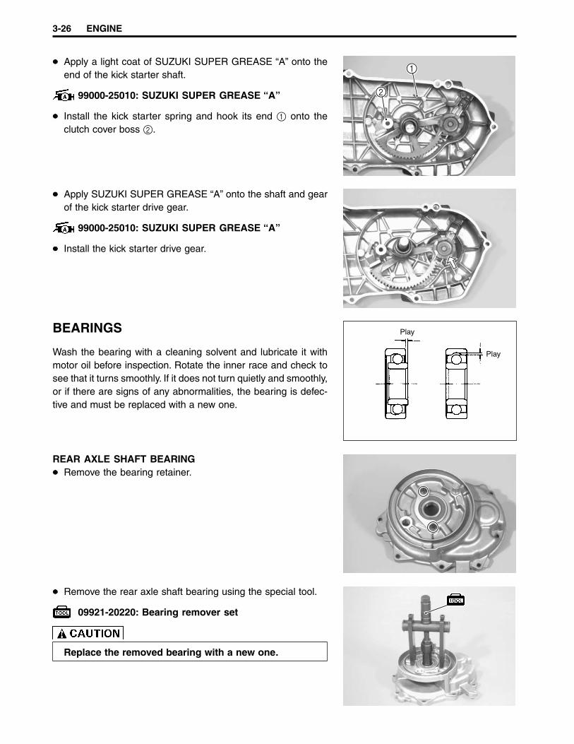
BEARINGS
Wash the bearing with a cleaning solvent and lubricate it withmotor oil before inspection. Rotate the inner race and check tosee that it turns smoothly. If it does not turn quietly and smoothly,or if there are signs of any abnormalities, the bearing is defec-tive and must be replaced with a new one.
REAR AXLE SHAFT BEARINGRemove the bearing retainer.
Remove the rear axle shaft bearing using the special tool.
09921-20220: Bearing remover set
Replace the removed bearing with a new one.
Play
Play
2
1

ENGINE 3-27
Install the rear axle shaft bearing using the special tool.
09913-70210: Bearing installer set
RIGHT DRIVESHAFT BEARING AND IDLE SHAFT BEARINGRemove the right driveshaft bearing and idle shaft bearingusing the special tools.
09921-20210: Bearing remover09930-30102: Sliding hammer
Replace the removed bearings with new ones.
LEFT DRIVESHAFT BEARINGRemove the left driveshaft bearing using the special tool.
09921-20220: Bearing remover set
Replace the removed bearing with a new one.
Install the left driveshaft bearing using the special tool.
09913-70210: Bearing installer set
Install the right driveshaft bearing and idle shaft bearing us-ing the special tool.
09913-70210: Bearing installer set

3-28 ENGINE
RIGHT CRANKSHAFT BEARINGRemove the right crankshaft bearings using the special tools.
09923-73210: Bearing remover09930-30102: Sliding hammer
Replace the removed bearing with a new one.
Install the right crankshaft bearing using the special tool.
09913-70210: Bearing installer set
LEFT CRANKSHAFT BEARINGRemove the left crankshaft bearing using the special tools.
09923-74510: Bearing remover09930-30102: Sliding hammer
Replace the removed bearing with a new one.
Install the left crankshaft bearing using the special tool.
09913-70210: Bearing installer set
OIL SEALS
Damage to the lip of the oil seal may result in leakage of the air-fuel mixture or gear oil. Inspect the oil seal and if it is damaged,replace it with a new one.
ENGINE 3-29
Install the oil seals into the crankcase and gearbox cover, asshown below.
Replace the removed oil seals with new ones.
Apply SUZUKI SUPER GREASE “A” to the lip of the oil seals.
99000-25010: SUZUKI SUPER GREASE “A”
REAR AXLE SHAFT OIL SEALRemove the rear axle shaft bearing. ( 3-26)Remove the rear axle shaft oil seal from the gearbox coverusing the special tool.
09913-50121: Oil seal remover
Replace the removed oil seal with a new one.
Install the rear axle shaft oil seal into the gearbox cover, slowly,using the special tool.
09913-70210: Bearing installer set
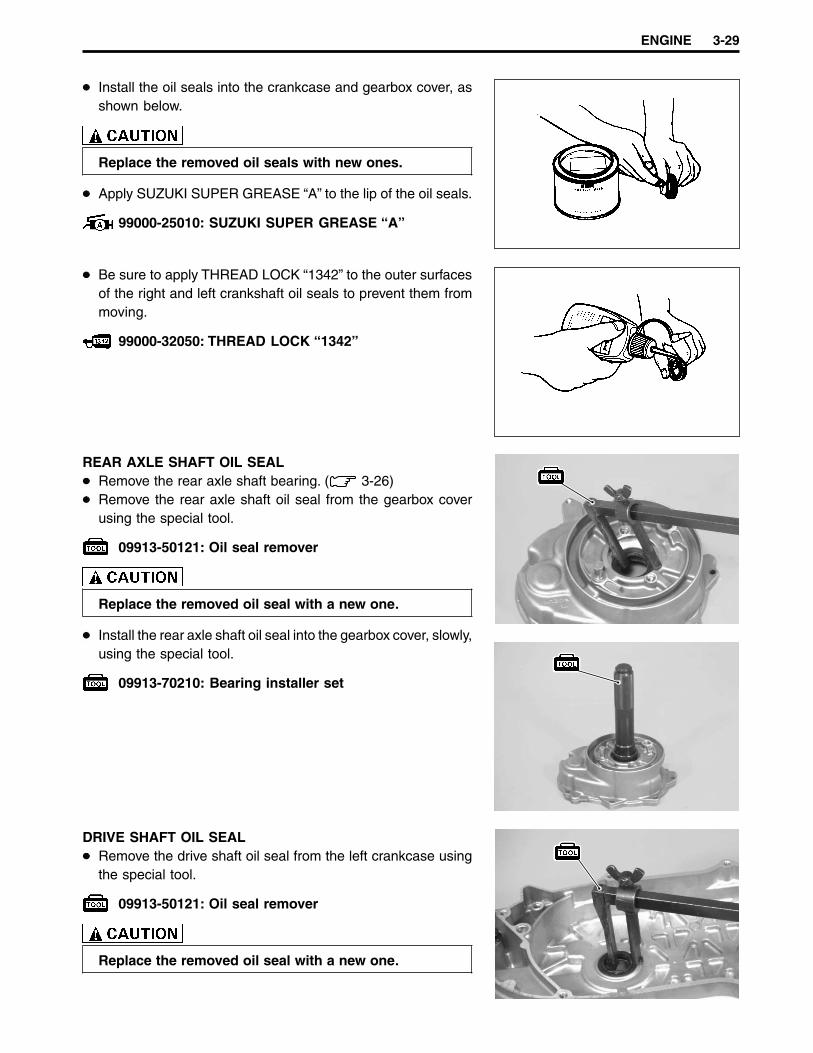
DRIVE SHAFT OIL SEALRemove the drive shaft oil seal from the left crankcase usingthe special tool.
09913-50121: Oil seal remover
Replace the removed oil seal with a new one.
Be sure to apply THREAD LOCK “1342” to the outer surfacesof the right and left crankshaft oil seals to prevent them frommoving.
99000-32050: THREAD LOCK “1342”
3-30 ENGINE
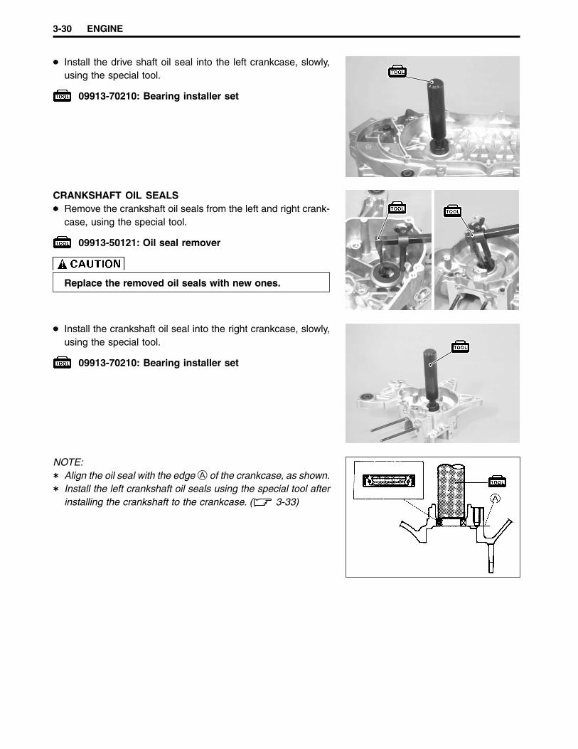
Install the drive shaft oil seal into the left crankcase, slowly,using the special tool.
09913-70210: Bearing installer set
CRANKSHAFT OIL SEALSRemove the crankshaft oil seals from the left and right crank-case, using the special tool.
09913-50121: Oil seal remover
Replace the removed oil seals with new ones.
NOTE:Align the oil seal with the edge A of the crankcase, as shown.Install the left crankshaft oil seals using the special tool afterinstalling the crankshaft to the crankcase. ( 3-33)
Install the crankshaft oil seal into the right crankcase, slowly,using the special tool.
09913-70210: Bearing installer set
ENGINE 3-31
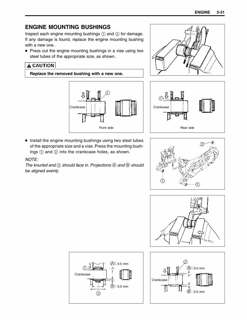
ENGINE MOUNTING BUSHINGSInspect each engine mounting bushings 1 and 2 for damage.If any damage is found, replace the engine mounting bushingwith a new one.
Press out the engine mounting bushings in a vise using twosteel tubes of the appropriate size, as shown.
Replace the removed bushing with a new one.
Install the engine mounting bushings using two steel tubesof the appropriate size and a vise. Press the mounting bush-ings 1 and 2 into the crankcase holes, as shown.
NOTE:The knurled end 3 should face in. Projections A and B shouldbe aligned evenly.
Crankcase
Front side
Crankcase
Rear side
Crankcase
0.5 mm
0.5 mm
Crankcase
0.5 mm
0.5 mm

3-32 ENGINE
ENGINE REASSEMBLY
Reassemble the engine in the reverse order of disassembly. Thefollowing steps require special attention or precautionary mea-sures should be taken.
NOTE:Apply engine oil to each running and sliding part before reas-sembling.
CRANKSHAFT
Mount the crankshaft into the right crankcase by pulling itsright end into the crankcase using the special tools.
09910-32812: Crankshaft installer09910-20116: Conrod holder
Never fit the crankshaft into the crankcase by strikingit with a plastic hammer. Always use the special tool,otherwise the crankshaft may be misaligned.
CRANKCASE
Install the two dowel pins 1 and new gaskets 2.Install the left crankcase onto the right crankcase.
Tighten the crankcase bolts.
NOTE:After the crankcase bolts have been tightened, make surethat the crankshaft rotates smoothly.If the crankshaft does not rotate smoothly, try to free it bytapping it with a plastic hammer.
1
1
2

ENGINE 3-33
Install the left crankshaft inner oil seal 1 using the specialtool.
09941-74910: Bearing installer
Apply SUZUKI SUPER GREASE “A” (approximately 10 g) tothe oil pump drive gear (on the crankshaft surface side).
99000-25010: SUZUKI SUPER GREASE “A”
Install the left crankshaft outer oil seal using the special tool.
09913-70210: Bearing installer set
28.5 mm
3-34 ENGINE
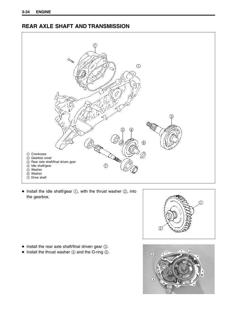
REAR AXLE SHAFT AND TRANSMISSION
1 Crankcase2 Gearbox cover3 Rear axle shaft/final driven gear4 Idle shaft/gear5 Washer6 Washer7 Drive shaft
Install the idle shaft/gear 1, with the thrust washer 2, intothe gearbox.
Install the rear axle shaft/final driven gear 3.Install the thrust washer 4 and the O-ring 5. 3
5
4
ENGINE 3-35
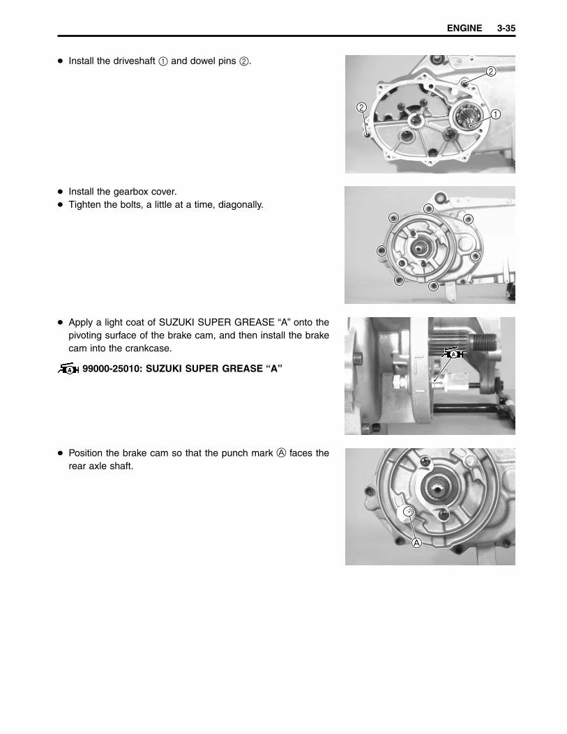
Install the driveshaft 1 and dowel pins 2.
Install the gearbox cover.Tighten the bolts, a little at a time, diagonally.
Apply a light coat of SUZUKI SUPER GREASE “A” onto thepivoting surface of the brake cam, and then install the brakecam into the crankcase.
99000-25010: SUZUKI SUPER GREASE “A”
Position the brake cam so that the punch mark A faces therear axle shaft.
2
2
1
A

3-36 ENGINE
Align the tang 1 on the brake lining wear indicator plate 2with the cutaway 3 on the brake cam. Then, slide the brakelining wear indicator plate onto the brake cam.
Install the return spring and brake cam lever onto the brakecam and tighten the brake cam lever nut to the specified torque.
Brake cam lever nut: 10 N·m (1.0 kgf-m)
Install the brake shoes and rear wheel.Tighten the rear axle nut to the specified torque.
NOTE:Apply final gear oil (10W-40) to the axle nut before tightening it.
Rear axle nut: 120 N·m (12.0 kgf-m)
GENERATOR
Remove any grease from the tapered portion of the crank-shaft and also from the generator rotor.Install the key 1, stator coil 2, and pickup coil 3.
2
1
3
ENGINE 3-37
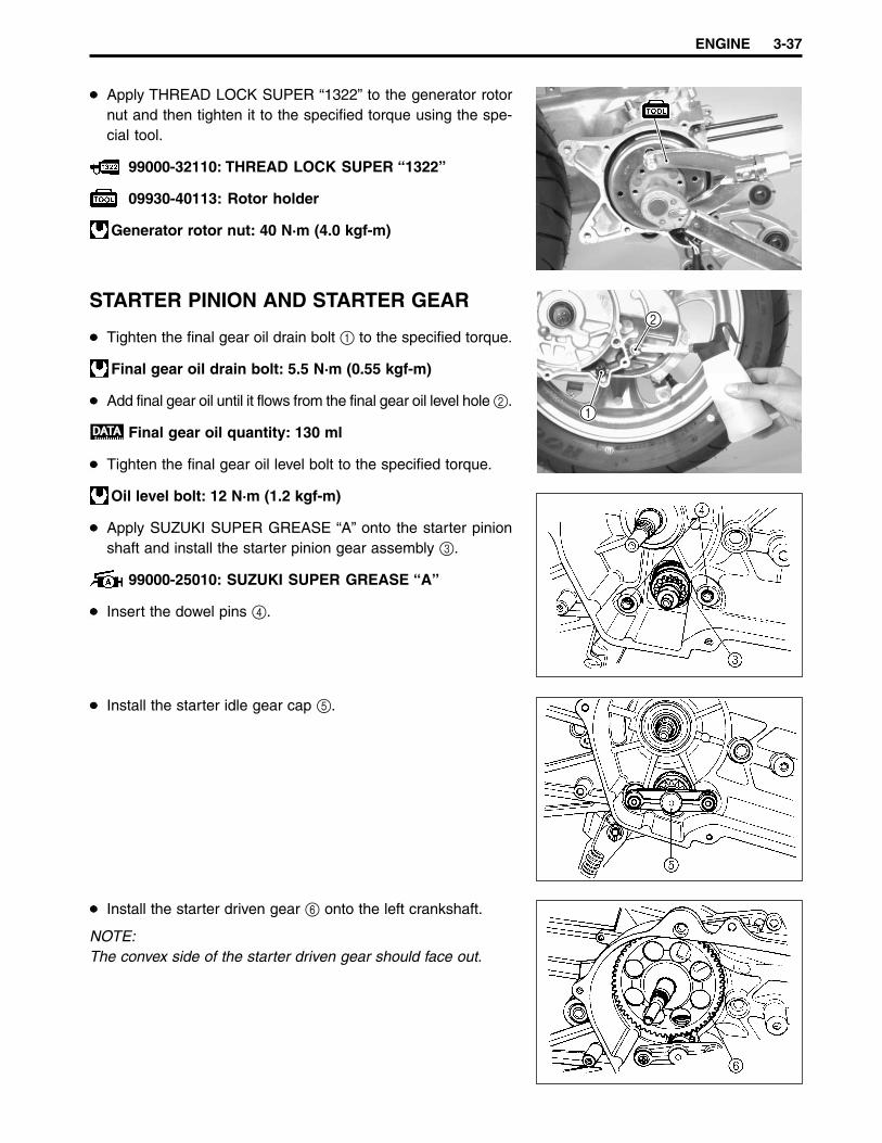
Apply THREAD LOCK SUPER “1322” to the generator rotornut and then tighten it to the specified torque using the spe-cial tool.
99000-32110: THREAD LOCK SUPER “1322”
09930-40113: Rotor holder
Generator rotor nut: 40 N·m (4.0 kgf-m)
STARTER PINION AND STARTER GEAR
Tighten the final gear oil drain bolt 1 to the specified torque.
Final gear oil drain bolt: 5.5 N·m (0.55 kgf-m)
Add final gear oil until it flows from the final gear oil level hole 2.
Final gear oil quantity: 130 ml
Tighten the final gear oil level bolt to the specified torque.
Oil level bolt: 12 N·m (1.2 kgf-m)
Apply SUZUKI SUPER GREASE “A” onto the starter pinionshaft and install the starter pinion gear assembly 3.
99000-25010: SUZUKI SUPER GREASE “A”
Insert the dowel pins 4.
Install the starter idle gear cap 5.
Install the starter driven gear 6 onto the left crankshaft.
NOTE:The convex side of the starter driven gear should face out.
1
2
3-38 ENGINE
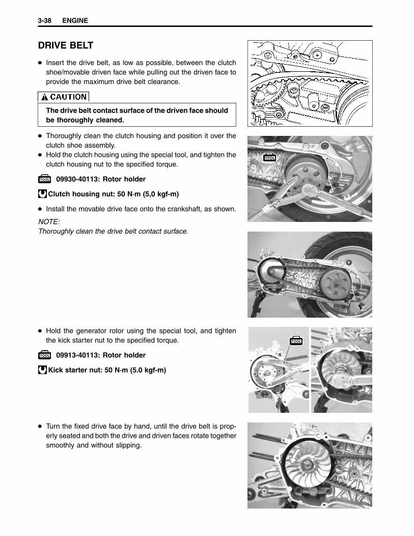
DRIVE BELT
Insert the drive belt, as low as possible, between the clutchshoe/movable driven face while pulling out the driven face toprovide the maximum drive belt clearance.
The drive belt contact surface of the driven face shouldbe thoroughly cleaned.
Thoroughly clean the clutch housing and position it over theclutch shoe assembly.Hold the clutch housing using the special tool, and tighten theclutch housing nut to the specified torque.
09930-40113: Rotor holder
Clutch housing nut: 50 N·m (5,0 kgf-m)
Install the movable drive face onto the crankshaft, as shown.
NOTE:Thoroughly clean the drive belt contact surface.
Hold the generator rotor using the special tool, and tightenthe kick starter nut to the specified torque.
09913-40113: Rotor holder
Kick starter nut: 50 N·m (5.0 kgf-m)
Turn the fixed drive face by hand, until the drive belt is prop-erly seated and both the drive and driven faces rotate togethersmoothly and without slipping.

ENGINE 3-39
Install the dowel pins 1 and new gaskets 2.
Install the clutch cover 3 and kick starter lever 4.
PISTON
Install the piston rings onto the piston.
1st: Keystone ring2nd: Rectangular ring and expander ring
NOTE:The piston rings should be installed with the mark facing up.
Position the piston ring gaps, as shown. Before inserting thepiston into the cylinder, check that the gaps are properly posi-tioned.
Securely install the circlip 1.
NOTE:The arrow mark 2 on the piston crown should be pointing to-wards the exhaust side.
Apply engine oil onto the piston pin, and then install the pis-ton.
CORRECT INCORRECT
12
2
1
3
4

3-40 ENGINE
CYLINDER
Apply engine oil onto the piston and cylinder wall surfaces,and then install the cylinder over the piston carefully.
CYLINDER HEAD
Tighten the cylinder head nuts diagonally, as shown, and tothe specified torque.
Cylinder head nut: 10 N·m (1.0 kgf-m)
OIL PUMP GEAR
Apply SUZUKI SUPER GREASE “A” onto the oil pump gear,and then install it.
99000-25010: SUZUKI SUPER GREASE “A”
INTAKE PIPE
Install the intake pipe and tighten the bolts securely.
NOTE:Be sure to use the special twist-off bolt A as shown.
EXHAUST PIPE/MUFFLER
Tighten the exhaust pipe mounting nut and bolt to the speci-fied torque.
Exhaust pipe mounting nut and bolt: 10 N·m (1.0 kgf-m)
A
FUEL AND LUBRICATION SYSTEM 4-1
FUEL AND LUBRICATION SYSTEM
4
CONTENTS
FUEL VALVE.................................................................................................... 4- 2FUEL TANK AND OIL TANK ........................................................................... 4- 3
REMOVAL ................................................................................................... 4- 3REMOUNTING ............................................................................................ 4- 4FUEL TANK CUSHIONS ............................................................................. 4- 5
CARBURETOR................................................................................................ 4- 6CONSTRUCTION ........................................................................................ 4- 6I. D. NO. LOCATION .................................................................................... 4- 6SPECIFICATIONS ....................................................................................... 4- 7REMOVAL ................................................................................................... 4- 8DISASSEMBLY ........................................................................................... 4- 8CLEANING .................................................................................................. 4-11INSPECTION AND ADJUSTMENT ............................................................ 4-11REASSEMBLY ............................................................................................ 4-12REMOUNTING ............................................................................................ 4-12
OIL PUMP ........................................................................................................ 4-13AIR BLEEDING ........................................................................................... 4-13DISCHARGE RATE CHECK ....................................................................... 4-13
4-2 FUEL AND LUBRICATION SYSTEM
FUEL VALVE
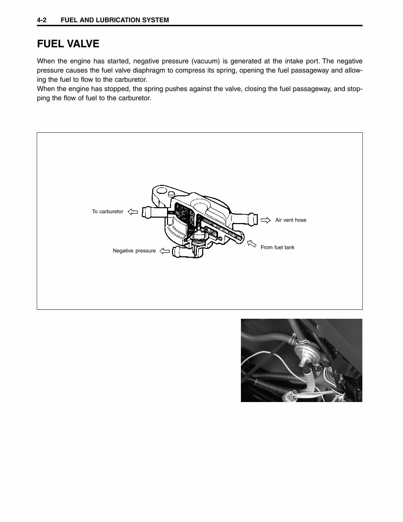
When the engine has started, negative pressure (vacuum) is generated at the intake port. The negativepressure causes the fuel valve diaphragm to compress its spring, opening the fuel passageway and allow-ing the fuel to flow to the carburetor.When the engine has stopped, the spring pushes against the valve, closing the fuel passageway, and stop-ping the flow of fuel to the carburetor.
To carburetor
Negative pressure
Air vent hose
From fuel tank

FUEL AND LUBRICATION SYSTEM 4-3
FUEL TANK AND OIL TANKREMOVAL
Gasoline is highly flammable and explosive.Keep heat, sparks, and flames away from gasoline.
Remove the frame cover. ( 5-4 and 5-5)
Disconnect the turn signal light lead wires 1 and license platelight coupler 2.
Disconnect the fuel level indicator switch coupler.
Disconnect the air vent hose 3 and fuel hose 4.
Remove the lower fuel tank cover mounting bolts.
2
1
3
4

4-4 FUEL AND LUBRICATION SYSTEM
Remove the fuel tank cap 1 and fuel tank 2.
NOTE:After removing the fuel tank, reinstall the fuel tank cap.
Disconnect the oil hose 3, oil level indicator switch coupler 4,and remove the oil tank 5.
REMOUNTING
Remount the fuel tank and oil tank in the reverse order of re-moval.
12
5
3
4
FUEL AND LUBRICATION SYSTEM 4-5
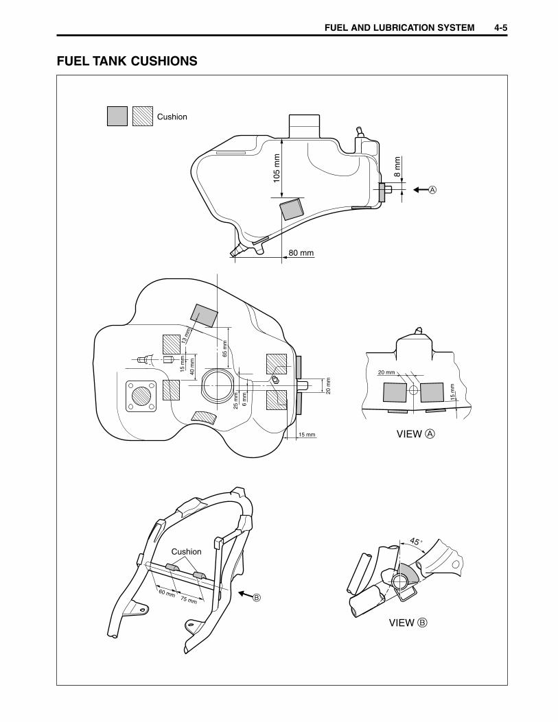
FUEL TANK CUSHIONS
15 mm
Cushion
80 mm
105
mm
8 m
m
13 m
m
65 m
m
40 m
m
15 m
m
25 m
m
6 m
m 20 m
m
20 mm
15 m
m
60 mm75 mm B
A
VIEW A
VIEW B
45˚Cushion
4-6 FUEL AND LUBRICATION SYSTEM
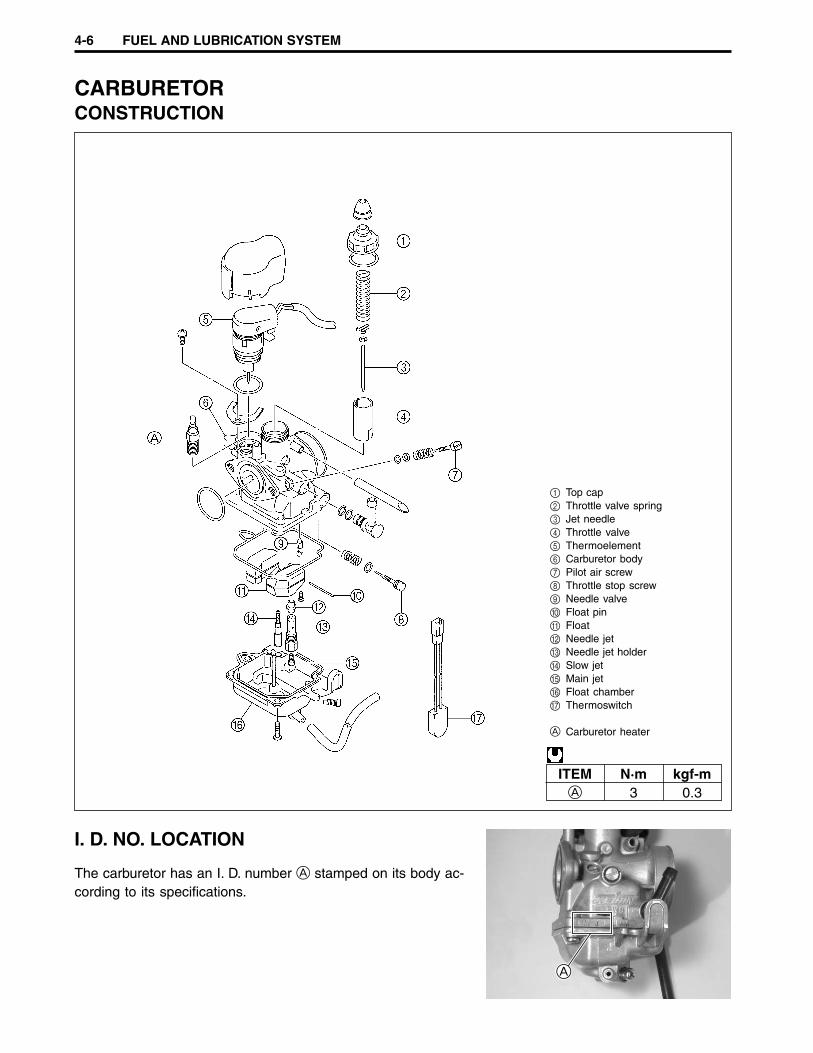
CARBURETORCONSTRUCTION
1 Top cap2 Throttle valve spring3 Jet needle4 Throttle valve5 Thermoelement6 Carburetor body7 Pilot air screw8 Throttle stop screw9 Needle valve0 Float pinA FloatB Needle jetC Needle jet holderD Slow jetE Main jetF Float chamberG Thermoswitch
A Carburetor heater
ITEM N·m kgf-mA 3 0.3
I. D. NO. LOCATION
The carburetor has an I. D. number A stamped on its body ac-cording to its specifications.
A

FUEL AND LUBRICATION SYSTEM 4-7
SPECIFICATIONS
ITEM SPECIFICATIONCarburetor type KEIHIN PWS14Bore size 14 mmI.D. No. 30F0Idle r/min 1 900 ± 200 r/minFloat height 5.1 ± 0.5 mmMain jet (M.J.) # 65Jet needle (J.N.) N5GJ-2ndSlow jet (S.J.) # 42Air screw (A.S.) 2 turns backThrottle cable play 2 – 4 mm

4-8 FUEL AND LUBRICATION SYSTEM
REMOVAL
Remove the trunk. ( 5-4)Remove the clamps, disconnect the thermoelement coupler 1and carburetor heater lead wire 2.
Disconnect the vacuum hose 3 and fuel hose 4.
Loosen the carburetor clamp screw and remove the carbure-tor mounting bolts.
Remove the top cap.
DISASSEMBLY
Remove the throttle cable from the slit in the throttle valve,and then remove the throttle valve 1 along with the jet needleand throttle valve spring 2.
2
1
3
4
1 2

FUEL AND LUBRICATION SYSTEM 4-9
Separate the jet needle 1 and throttle valve 2.
Remove the each carburetor hoses.Remove the float chamber 3.
Remove the float 4 and needle valve 5 by removing thefloat pin 6.
When removing the float pin, be careful not to damagethe carburetor body and float.
Remove the main jet 7, needle jet holder 8, needle jet 9,and pilot jet 0.
Remove the throttle stop screw A and pilot air screw B.
Do not use wire to clean the passageways, valve seat,and jets. Use compressed air only.
2
1
3
4
6
5
8
0 9
7
A
B

4-10 FUEL AND LUBRICATION SYSTEM
Remove the thermoelement cover 1 and remove the ther-moelement 2.
Do not disassemble the thermoelement. It is not ser-viceable.
Remove the carburetor heater.
12
FUEL AND LUBRICATION SYSTEM 4-11
CLEANING
Some carburetor cleaning chemicals, especially dip-type soaking solutions, are very corrosive and mustbe handled carefully. Always follow the chemicalmanufacturer’s instructions for proper use, handlingand storage.
Clean all jets with a spray-type carburetor cleaner and drythem using compressed air.Clean all circuits of the carburetor thoroughly––not just theperceived problem area. Clean the circuits in the carburetorbody with a spray-type cleaner. If necessary, soak each cir-cuit in a dip-type cleaning solution to loosen dirt and varnish.Dry the carburetor body using compressed air.
Do not use wire to clean the passageways, valve seat,and jets. If the components cannot be cleaned with aspray-type cleaner it may be necessary to soak themin a dip-type cleaning solution. Always follow the chemi-cal manufacturer’s instructions for proper use andcleaning of the carburetor components.
After cleaning, reassemble the carburetor with new O-rings.
Replace the removed O-rings with new ones.
INSPECTION AND ADJUSTMENT
Check the following items for any damage or clogging. If anydamages are found, replace the damaged parts with new ones.
Main jet Throttle valve Pilot jet Float Needle jet Needle valve Pilot air screw Pilot outlet and bypass holes Thermoelement ( 6-21) Carburetor heater ( 6-22)
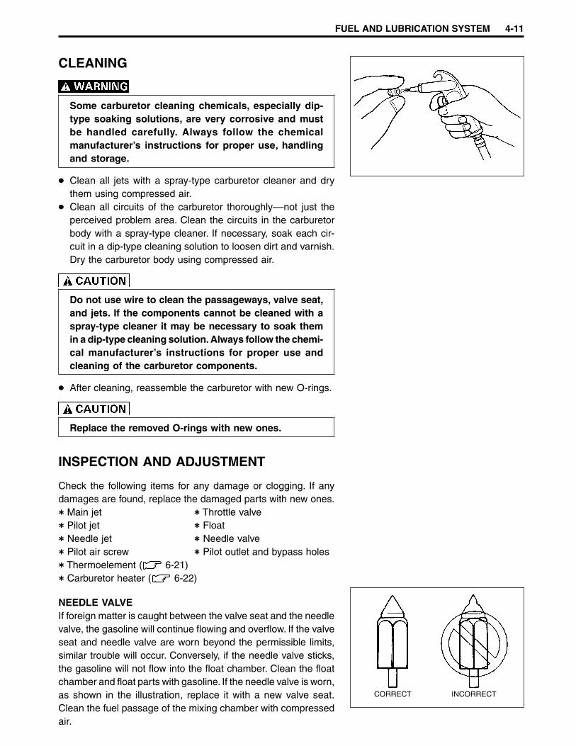
NEEDLE VALVEIf foreign matter is caught between the valve seat and the needlevalve, the gasoline will continue flowing and overflow. If the valveseat and needle valve are worn beyond the permissible limits,similar trouble will occur. Conversely, if the needle valve sticks,the gasoline will not flow into the float chamber. Clean the floatchamber and float parts with gasoline. If the needle valve is worn,as shown in the illustration, replace it with a new valve seat.Clean the fuel passage of the mixing chamber with compressedair.
CORRECT INCORRECT
4-12 FUEL AND LUBRICATION SYSTEM
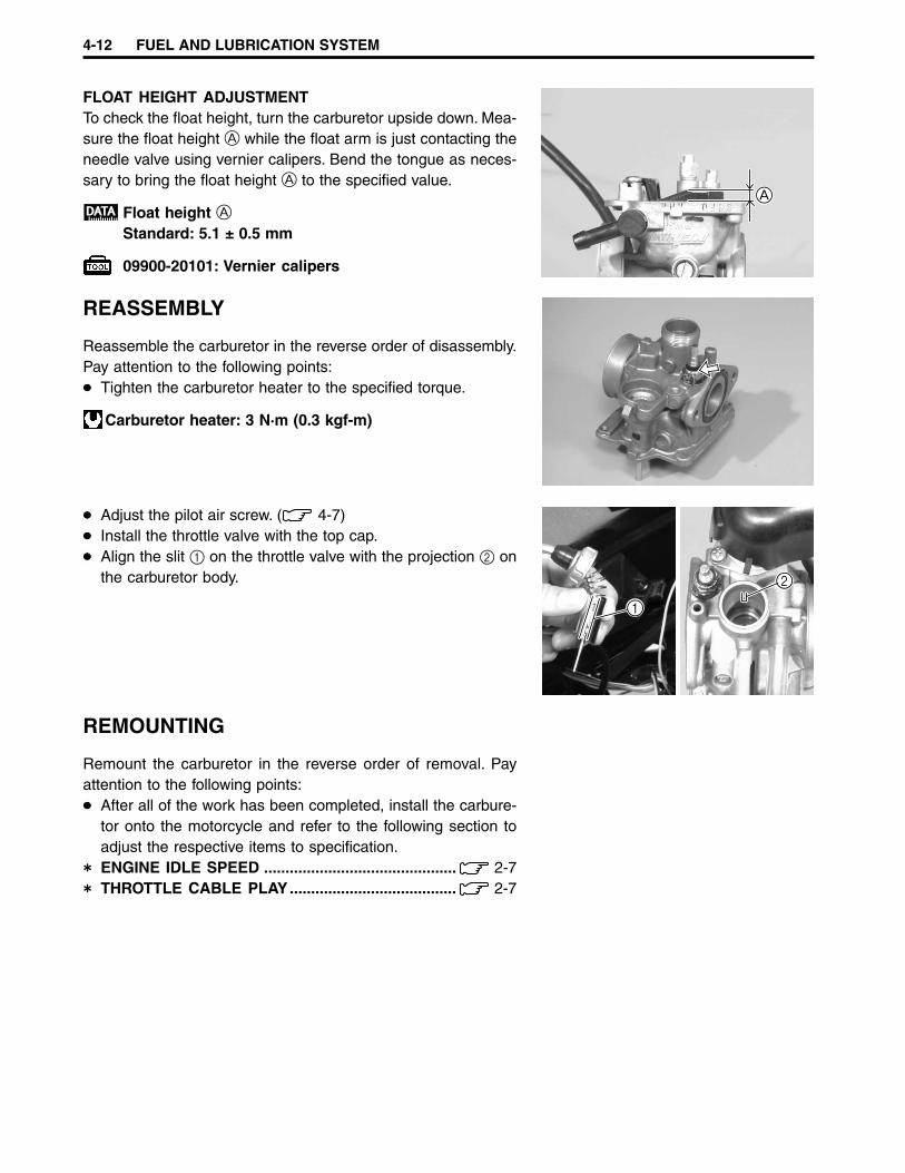
FLOAT HEIGHT ADJUSTMENTTo check the float height, turn the carburetor upside down. Mea-sure the float height A while the float arm is just contacting theneedle valve using vernier calipers. Bend the tongue as neces-sary to bring the float height A to the specified value.
Float height AStandard: 5.1 ± 0.5 mm
09900-20101: Vernier calipers
REASSEMBLY
Reassemble the carburetor in the reverse order of disassembly.Pay attention to the following points:
Tighten the carburetor heater to the specified torque.
Carburetor heater: 3 N·m (0.3 kgf-m)
Adjust the pilot air screw. ( 4-7)Install the throttle valve with the top cap.Align the slit 1 on the throttle valve with the projection 2 onthe carburetor body.
REMOUNTING
Remount the carburetor in the reverse order of removal. Payattention to the following points:
After all of the work has been completed, install the carbure-tor onto the motorcycle and refer to the following section toadjust the respective items to specification.ENGINE IDLE SPEED ............................................. 2-7THROTTLE CABLE PLAY....................................... 2-7
A
1
2
FUEL AND LUBRICATION SYSTEM 4-13
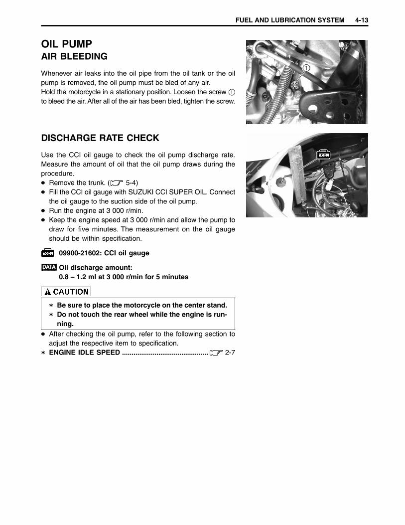
OIL PUMPAIR BLEEDING
Whenever air leaks into the oil pipe from the oil tank or the oilpump is removed, the oil pump must be bled of any air.Hold the motorcycle in a stationary position. Loosen the screw 1to bleed the air. After all of the air has been bled, tighten the screw.
DISCHARGE RATE CHECK
Use the CCI oil gauge to check the oil pump discharge rate.Measure the amount of oil that the oil pump draws during theprocedure.
Remove the trunk. ( 5-4)Fill the CCI oil gauge with SUZUKI CCI SUPER OIL. Connectthe oil gauge to the suction side of the oil pump.Run the engine at 3 000 r/min.Keep the engine speed at 3 000 r/min and allow the pump todraw for five minutes. The measurement on the oil gaugeshould be within specification.
09900-21602: CCI oil gauge
Oil discharge amount:0.8 – 1.2 ml at 3 000 r/min for 5 minutes
Be sure to place the motorcycle on the center stand.Do not touch the rear wheel while the engine is run-ning.
After checking the oil pump, refer to the following section toadjust the respective item to specification.ENGINE IDLE SPEED ............................................. 2-7
1
CHASSIS 5-1
CHASSIS
5
CONTENTS
EXTERIOR PARTS ...................................................................................................... 5- 2CONSTRUCTION .................................................................................................... 5- 2REMOVAL ............................................................................................................... 5- 3REMOUNTING ........................................................................................................ 5- 5
FRONT WHEEL ........................................................................................................... 5- 6CONSTRUCTION .................................................................................................... 5- 6REMOVAL ............................................................................................................... 5- 6INSPECTION AND DISASSEMBLY ....................................................................... 5- 7REASSEMBLY AND REMOUNTING ..................................................................... 5- 8
FRONT BRAKE ........................................................................................................... 5-10CONSTRUCTION .................................................................................................... 5-10BRAKE PADS REPLACEMENT ............................................................................. 5-11BRAKE FLUID REPLACEMENT ............................................................................ 5-12BRAKE CALIPER REMOVAL AND DISASSEMBLY ............................................ 5-12BRAKE CALIPER INSPECTION ............................................................................ 5-13BRAKE CALIPER REASSEMBLY AND REMOUNTING ...................................... 5-14BRAKE DISC INSPECTION ................................................................................... 5-15MASTER CYLINDER REMOVAL AND DISASSEMBLY ....................................... 5-15MASTER CYLINDER INSPECTION....................................................................... 5-16MASTER CYLINDER REASSEMBLY AND REMOUNTING ................................. 5-17
FRONT SUSPENSION ................................................................................................ 5-18CONSTRUCTION .................................................................................................... 5-18REMOVAL AND DISASSEMBLY ........................................................................... 5-18INSPECTION ........................................................................................................... 5-20REASSEMBLY AND REMOUNTING ..................................................................... 5-20
HANDLEBAR COVERS AND SPEEDOMETER ASSEMBLY.................................... 5-22CONSTRUCTION .................................................................................................... 5-22REMOVAL ............................................................................................................... 5-23REMOUNTING ........................................................................................................ 5-24
STEERING STEM ........................................................................................................ 5-25CONSTRUCTION .................................................................................................... 5-25REMOVAL AND DISASSEMBLY ........................................................................... 5-25INSPECTION ........................................................................................................... 5-27REASSEMBLY AND REMOUNTING ..................................................................... 5-28
REAR WHEEL, REAR BRAKE, AND REAR SHOCK ABSORBER .......................... 5-30CONSTRUCTION .................................................................................................... 5-30REMOVAL AND DISASSEMBLY ........................................................................... 5-30INSPECTION ........................................................................................................... 5-31REASSEMBLY AND REMOUNTING ..................................................................... 5-32
TIRES AND WHEELS .................................................................................................. 5-33TIRE REMOVAL ...................................................................................................... 5-33INSPECTION ........................................................................................................... 5-33INSTALLATION ....................................................................................................... 5-34

5-2 CHASSIS
EXTERIOR PARTSCONSTRUCTION
1Fr
ame
cove
r (R
)2
Fram
e co
ver
(L)
3Tr
unk
4S
ide
leg
shie
ld (
R)
5S
ide
leg
shie
ld (
L)6
Low
er le
g sh
ield
7Le
g sh
ield
8C
over
9B
atte
ry h
olde
r co
ver
0F
ootb
oard
AFr
ont
leg
shie
ld

CHASSIS 5-3
REMOVALLEG SHIELD
Remove the battery. ( 6-30)Remove the side leg shields 1.
Remove the frame cover.Remove the footboard 2.
Remove the cover 3.
Remove the front leg shield mounting screws.
Disconnect the headlight lead wires 4 and remove the frontleg shield 5.
1
2
3
4 5
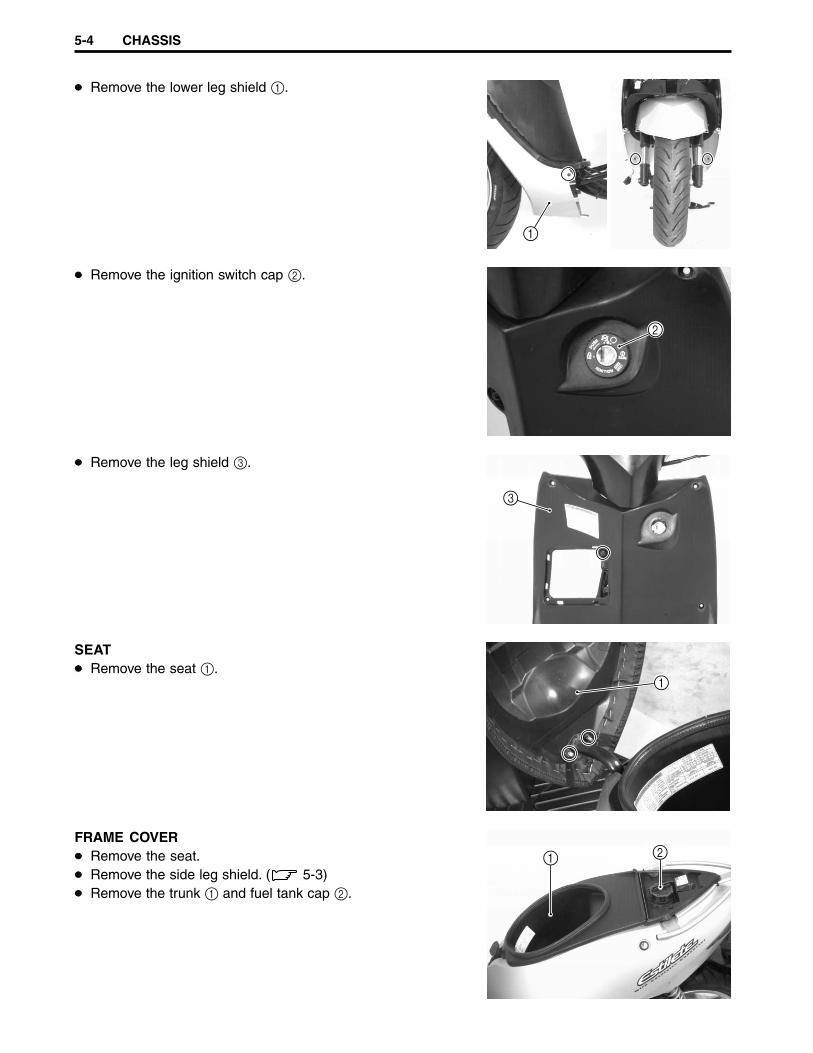
5-4 CHASSIS
Remove the lower leg shield 1.
Remove the ignition switch cap 2.
Remove the leg shield 3.
SEATRemove the seat 1.
FRAME COVERRemove the seat.Remove the side leg shield. ( 5-3)Remove the trunk 1 and fuel tank cap 2.
1
2
3
1
21

CHASSIS 5-5
Remove the upper fuel tank cover 1.After removing the upper fuel tank cover, reinstall the fuel tankcap.
Remove the passenger grab handle 2.
Remove the frame cover mounting screw.
Disconnect the seat lock cable 3, brake light/taillight leadwires 4, and remove the frame cover 5.
REMOUNTING
Remount the leg shield, seat, and frame cover in the reverseorder of removal.
1
2
43
5
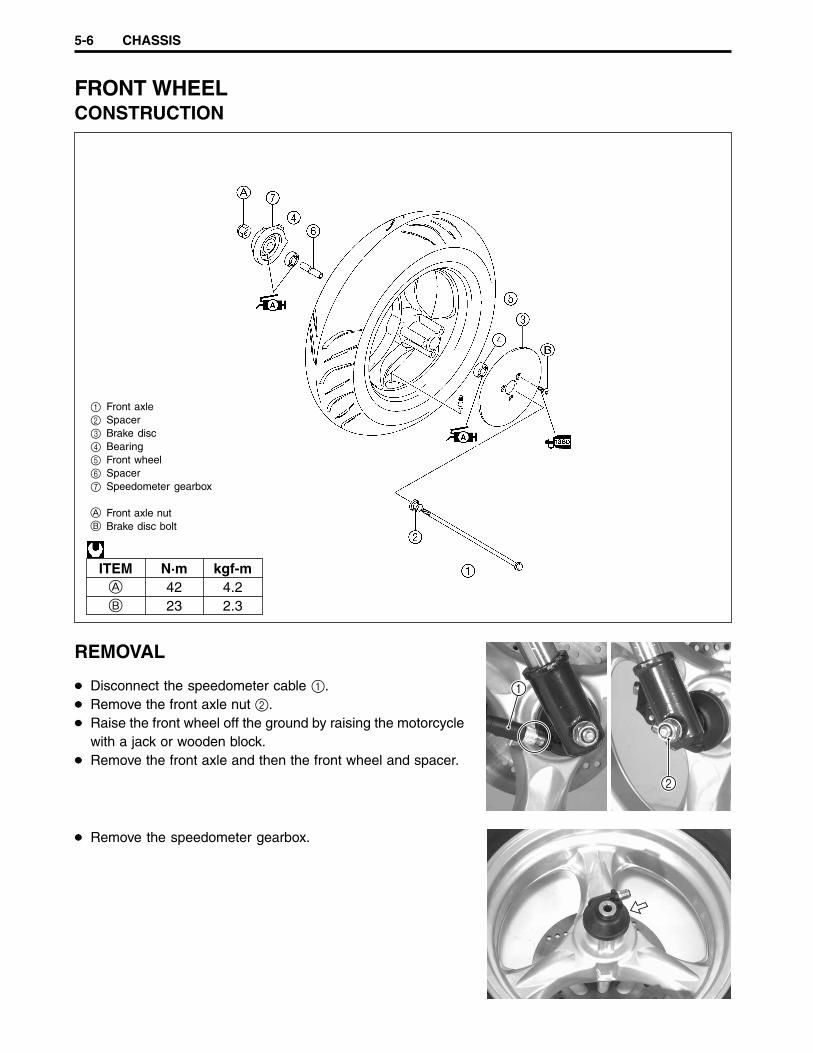
5-6 CHASSIS
FRONT WHEELCONSTRUCTION
1 Front axle2 Spacer3 Brake disc4 Bearing5 Front wheel6 Spacer7 Speedometer gearbox
A Front axle nutB Brake disc bolt
ITEM N·m kgf-mA 42 4.2B 23 2.3
REMOVAL
Disconnect the speedometer cable 1.Remove the front axle nut 2.Raise the front wheel off the ground by raising the motorcyclewith a jack or wooden block.Remove the front axle and then the front wheel and spacer.
Remove the speedometer gearbox.
1
2
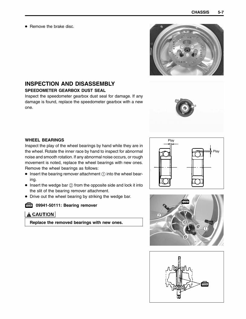
CHASSIS 5-7
Remove the brake disc.
INSPECTION AND DISASSEMBLYSPEEDOMETER GEARBOX DUST SEALInspect the speedometer gearbox dust seal for damage. If anydamage is found, replace the speedometer gearbox with a newone.
WHEEL BEARINGSInspect the play of the wheel bearings by hand while they are inthe wheel. Rotate the inner race by hand to inspect for abnormalnoise and smooth rotation. If any abnormal noise occurs, or roughmovement is noted, replace the wheel bearings with new ones.Remove the wheel bearings as follows:
Insert the bearing remover attachment 1 into the wheel bear-ing.Insert the wedge bar 2 from the opposite side and lock it intothe slit of the bearing remover attachment.Drive out the wheel bearing by striking the wedge bar.
09941-50111: Bearing remover
Replace the removed bearings with new ones.
Play
Play
2
1
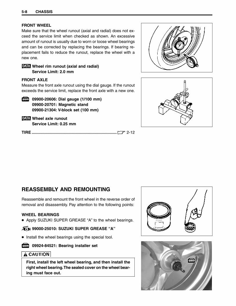
5-8 CHASSIS
FRONT WHEELMake sure that the wheel runout (axial and radial) does not ex-ceed the service limit when checked as shown. An excessiveamount of runout is usually due to worn or loose wheel bearingsand can be corrected by replacing the bearings. If bearing re-placement fails to reduce the runout, replace the wheel with anew one.
Wheel rim runout (axial and radial)Service Limit: 2.0 mm
FRONT AXLEMeasure the front axle runout using the dial gauge. If the runoutexceeds the service limit, replace the front axle with a new one.
09900-20606: Dial gauge (1/100 mm)09900-20701: Magnetic stand09900-21304: V-block set (100 mm)
Wheel axle runoutService Limit: 0.25 mm
TIRE ............................................................................ 2-12
REASSEMBLY AND REMOUNTING
Reassemble and remount the front wheel in the reverse order ofremoval and disassembly. Pay attention to the following points:
WHEEL BEARINGSApply SUZUKI SUPER GREASE “A” to the wheel bearings.
99000-25010: SUZUKI SUPER GREASE “A”
Install the wheel bearings using the special tool.
09924-84521: Bearing installer set
First, install the left wheel bearing, and then install theright wheel bearing. The sealed cover on the wheel bear-ing must face out.

CHASSIS 5-9
BRAKE DISCMake sure that the brake disc is clean and free of any grease.Apply THREAD LOCK SUPER “1360” to the brake disc mount-ing bolts and tighten them to the specified torque.
99000-32130: THREAD LOCK SUPER “1360”
Brake disc mounting bolt: 23 N·m (2.3 kgf-m)
SPEEDOMETER GEARBOXApply SUZUKI SUPER GREASE “A” to the teeth of the speed-ometer gear before installing the speedometer gearbox.
99000-25010: SUZUKI SUPER GREASE “A”
Align the grooves 1 on the speedometer gearbox with thelugs 2 on the wheel hub.
FRONT WHEELTighten the front axle nut to the specified torque.
Front axle nut: 42 N·m (4.2 kgf-m)
2 1
1 Bearing (L)2 Spacer3 Clearance4 Bearing (R)

5-10 CHASSIS
FRONT BRAKECONSTRUCTION
1 Cap2 Diaphragm3 Master cylinder4 Piston set5 Push rod6 Dust boot7 Brake hose8 Caliper9 Piston0 Piston and dust sealA ShimB Pad setC Pad mounting pinD O-ring
A Master cylinder mounting boltB Brake hose union boltC Air bleeder valveD Brake caliper housing boltE Brake caliper mounting bolt
ITEM N·m kgf-mA 10 1.0B 23 2.3C 7.5 0.75D 26 2.6E 32 3.2
The brake system is filled with an glycol-based brake fluid, which is classified DOT 4. Do notuse or mix other types of brake fluid, such as silicone-based and petroleum-based brakefluids when refilling the brake system, otherwise serious damage to the brake system willresult.Do not use any brake fluid taken from old, used, or unsealed containers.Do not reuse brake fluid left over from the last servicing or which has been stored for a longperiod of time.When storing brake fluid, be sure to seal the container completely and keep it out of thereach of children.When replenishing brake fluid, be sure not to get any dust or other foreign materials in thefluid.When washing brake components, always use new brake fluid. Do not use cleaning solvent.A contaminated brake disc or brake pad reduces braking performance. Discard contami-nated pads and clean the brake disc with high-quality brake cleaner or a neutral detergent.
Handle brake fluid with care: the fluid reacts chemically with paint, plastics, rubbermaterial, etc.
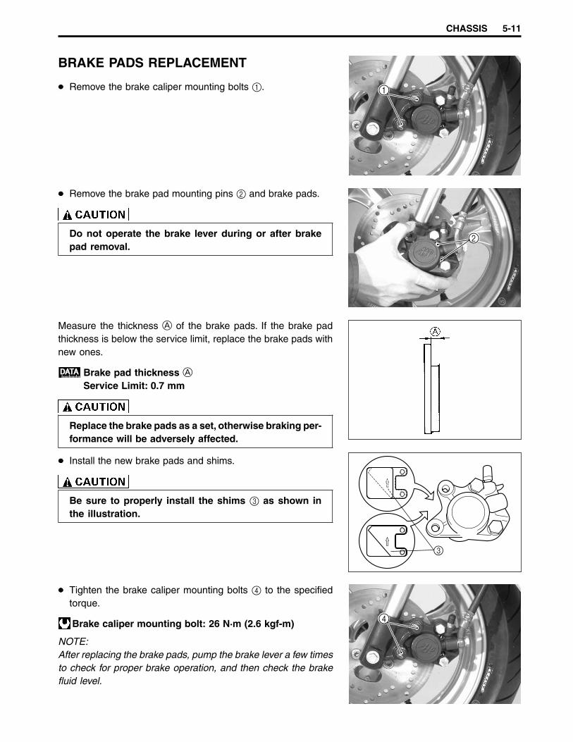
CHASSIS 5-11
BRAKE PADS REPLACEMENT
Remove the brake caliper mounting bolts 1.
Remove the brake pad mounting pins 2 and brake pads.
Do not operate the brake lever during or after brakepad removal.
Measure the thickness A of the brake pads. If the brake padthickness is below the service limit, replace the brake pads withnew ones.
Brake pad thickness AService Limit: 0.7 mm
Replace the brake pads as a set, otherwise braking per-formance will be adversely affected.
Install the new brake pads and shims.
Be sure to properly install the shims 3 as shown inthe illustration.
Tighten the brake caliper mounting bolts 4 to the specifiedtorque.
Brake caliper mounting bolt: 26 N·m (2.6 kgf-m)
NOTE:After replacing the brake pads, pump the brake lever a few timesto check for proper brake operation, and then check the brakefluid level.
3
1
2
4
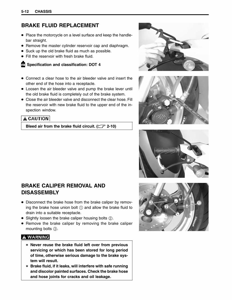
5-12 CHASSIS
BRAKE FLUID REPLACEMENT
Place the motorcycle on a level surface and keep the handle-bar straight.Remove the master cylinder reservoir cap and diaphragm.Suck up the old brake fluid as much as possible.Fill the reservoir with fresh brake fluid.
Specification and classification: DOT 4
BRAKE CALIPER REMOVAL ANDDISASSEMBLY
Disconnect the brake hose from the brake caliper by remov-ing the brake hose union bolt 1 and allow the brake fluid todrain into a suitable receptacle.Slightly loosen the brake caliper housing bolts 2.Remove the brake caliper by removing the brake calipermounting bolts 3.
Never reuse the brake fluid left over from previousservicing or which has been stored for long periodof time, otherwise serious damage to the brake sys-tem will result.Brake fluid, if it leaks, will interfere with safe runningand discolor painted surfaces. Check the brake hoseand hose joints for cracks and oil leakage.
Connect a clear hose to the air bleeder valve and insert theother end of the hose into a receptacle.Loosen the air bleeder valve and pump the brake lever untilthe old brake fluid is completely out of the brake system.Close the air bleeder valve and disconnect the clear hose. Fillthe reservoir with new brake fluid to the upper end of the in-spection window.
Bleed air from the brake fluid circuit. ( 2-10)
32
1
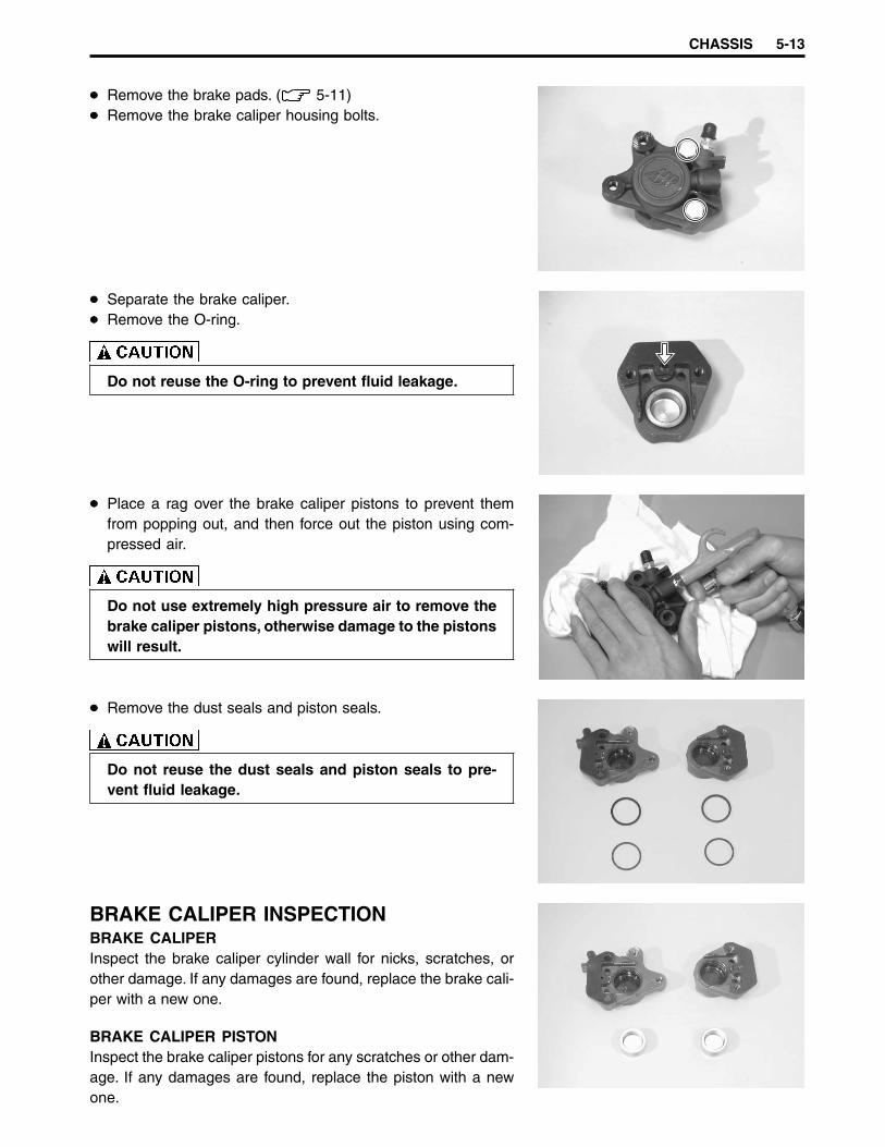
CHASSIS 5-13
Remove the brake pads. ( 5-11)Remove the brake caliper housing bolts.
Separate the brake caliper.Remove the O-ring.
Do not reuse the O-ring to prevent fluid leakage.
Place a rag over the brake caliper pistons to prevent themfrom popping out, and then force out the piston using com-pressed air.
Do not use extremely high pressure air to remove thebrake caliper pistons, otherwise damage to the pistonswill result.
Remove the dust seals and piston seals.
Do not reuse the dust seals and piston seals to pre-vent fluid leakage.
BRAKE CALIPER INSPECTIONBRAKE CALIPERInspect the brake caliper cylinder wall for nicks, scratches, orother damage. If any damages are found, replace the brake cali-per with a new one.
BRAKE CALIPER PISTONInspect the brake caliper pistons for any scratches or other dam-age. If any damages are found, replace the piston with a newone.
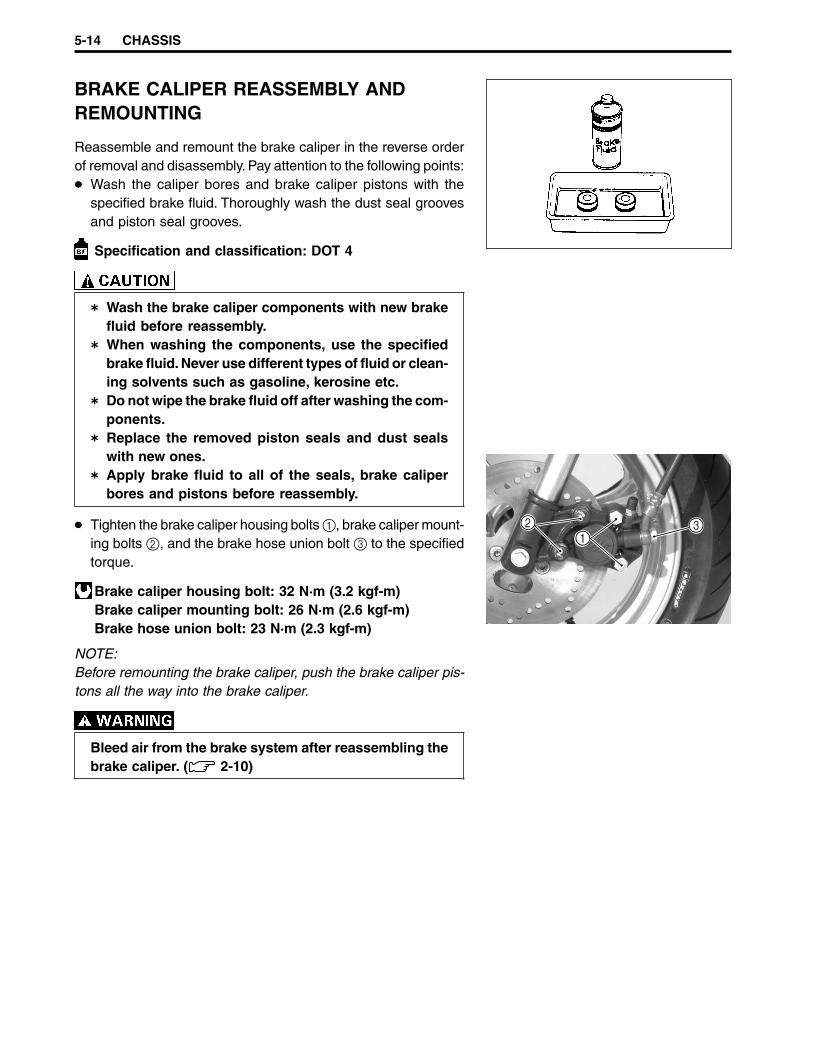
5-14 CHASSIS
BRAKE CALIPER REASSEMBLY ANDREMOUNTING
Reassemble and remount the brake caliper in the reverse orderof removal and disassembly. Pay attention to the following points:
Wash the caliper bores and brake caliper pistons with thespecified brake fluid. Thoroughly wash the dust seal groovesand piston seal grooves.
Specification and classification: DOT 4
Wash the brake caliper components with new brakefluid before reassembly.When washing the components, use the specifiedbrake fluid. Never use different types of fluid or clean-ing solvents such as gasoline, kerosine etc.Do not wipe the brake fluid off after washing the com-ponents.Replace the removed piston seals and dust sealswith new ones.Apply brake fluid to all of the seals, brake caliperbores and pistons before reassembly.
Tighten the brake caliper housing bolts 1, brake caliper mount-ing bolts 2, and the brake hose union bolt 3 to the specifiedtorque.
Brake caliper housing bolt: 32 N·m (3.2 kgf-m)Brake caliper mounting bolt: 26 N·m (2.6 kgf-m)Brake hose union bolt: 23 N·m (2.3 kgf-m)
NOTE:Before remounting the brake caliper, push the brake caliper pis-tons all the way into the brake caliper.
Bleed air from the brake system after reassembling thebrake caliper. ( 2-10)
21
3
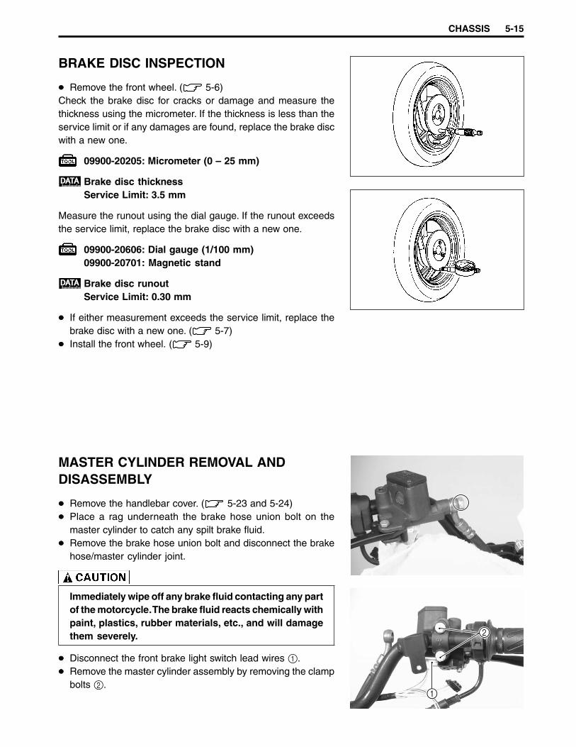
CHASSIS 5-15
BRAKE DISC INSPECTION
Remove the front wheel. ( 5-6)Check the brake disc for cracks or damage and measure thethickness using the micrometer. If the thickness is less than theservice limit or if any damages are found, replace the brake discwith a new one.
09900-20205: Micrometer (0 – 25 mm)
Brake disc thicknessService Limit: 3.5 mm
Measure the runout using the dial gauge. If the runout exceedsthe service limit, replace the brake disc with a new one.
09900-20606: Dial gauge (1/100 mm)09900-20701: Magnetic stand
Brake disc runoutService Limit: 0.30 mm
If either measurement exceeds the service limit, replace thebrake disc with a new one. ( 5-7)Install the front wheel. ( 5-9)
MASTER CYLINDER REMOVAL ANDDISASSEMBLY
Remove the handlebar cover. ( 5-23 and 5-24)Place a rag underneath the brake hose union bolt on themaster cylinder to catch any spilt brake fluid.Remove the brake hose union bolt and disconnect the brakehose/master cylinder joint.
Immediately wipe off any brake fluid contacting any partof the motorcycle. The brake fluid reacts chemically withpaint, plastics, rubber materials, etc., and will damagethem severely.
Disconnect the front brake light switch lead wires 1.Remove the master cylinder assembly by removing the clampbolts 2.
2
1

5-16 CHASSIS
Remove the brake lever and brake light switch.
Remove the dust boot and push rod.
Remove the circlip.
Remove the piston/secondary cup 1 and return spring 2.Remove the master cylinder reservoir cap 3 and diaphragm 4.Drain the brake fluid.
MASTER CYLINDER INSPECTIONMASTER CYLINDERInspect the master cylinder bore for any scratches or other dam-age. If any damages are found, replace the master cylinder witha new one.
34
2
1

CHASSIS 5-17
PISTONInspect the piston surface for any scratches or other damage. Ifany damages are found, replace the piston with a new one.
RUBBER PARTSInspect the primary cup, secondary cup and dust seal for wearor damage. If any damages are found, replace the piston/sec-ondary cup, and dust seal with new ones.
MASTER CYLINDER REASSEMBLY ANDREMOUNTING
Reassemble and remount the master cylinder in the reverse or-der of removal and disassembly. Pay attention to the followingpoints:
Wash the master cylinder components with newbrake fluid before reassembly.Do not wipe the brake fluid off after washing the com-ponents.When washing the components, use the specifiedbrake fluid. Never use different types of fluid or clean-ing solvents such as gasoline, kerosine, etc.Apply brake fluid to the master cylinder bore and allof the master cylinder components before reassem-bly.
Specification and classification: DOT 4
When remounting the master cylinder on the handlebar, alignthe master cylinder holder’s mating surface 1 with the punchmark 2 on the handlebar, and then tighten the upper clampbolt first.
Master cylinder clamp bolt: 10 N·m (1.0 kgf-m)
Tighten the brake hose union bolt to the specified torque.
Brake hose union bolt: 23 N·m (2.3 kgf-m)
Bleed air from the brake system after reassembling themaster cylinder. ( 2-10)
21
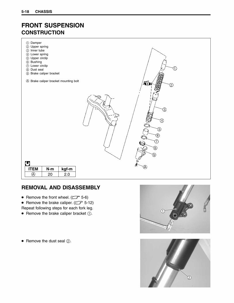
5-18 CHASSIS
FRONT SUSPENSIONCONSTRUCTION
1 Damper2 Upper spring3 Inner tube4 Lower spring5 Upper circlip6 Bushing7 Lower circlip8 Dust seal9 Brake caliper bracket
A Brake caliper bracket mounting bolt
ITEM N·m kgf-mA 20 2.0
REMOVAL AND DISASSEMBLY
Remove the front wheel. ( 5-6)Remove the brake caliper. ( 5-12)
Repeat following steps for each fork leg.Remove the brake caliper bracket 1.
Remove the dust seal 2.
1
2
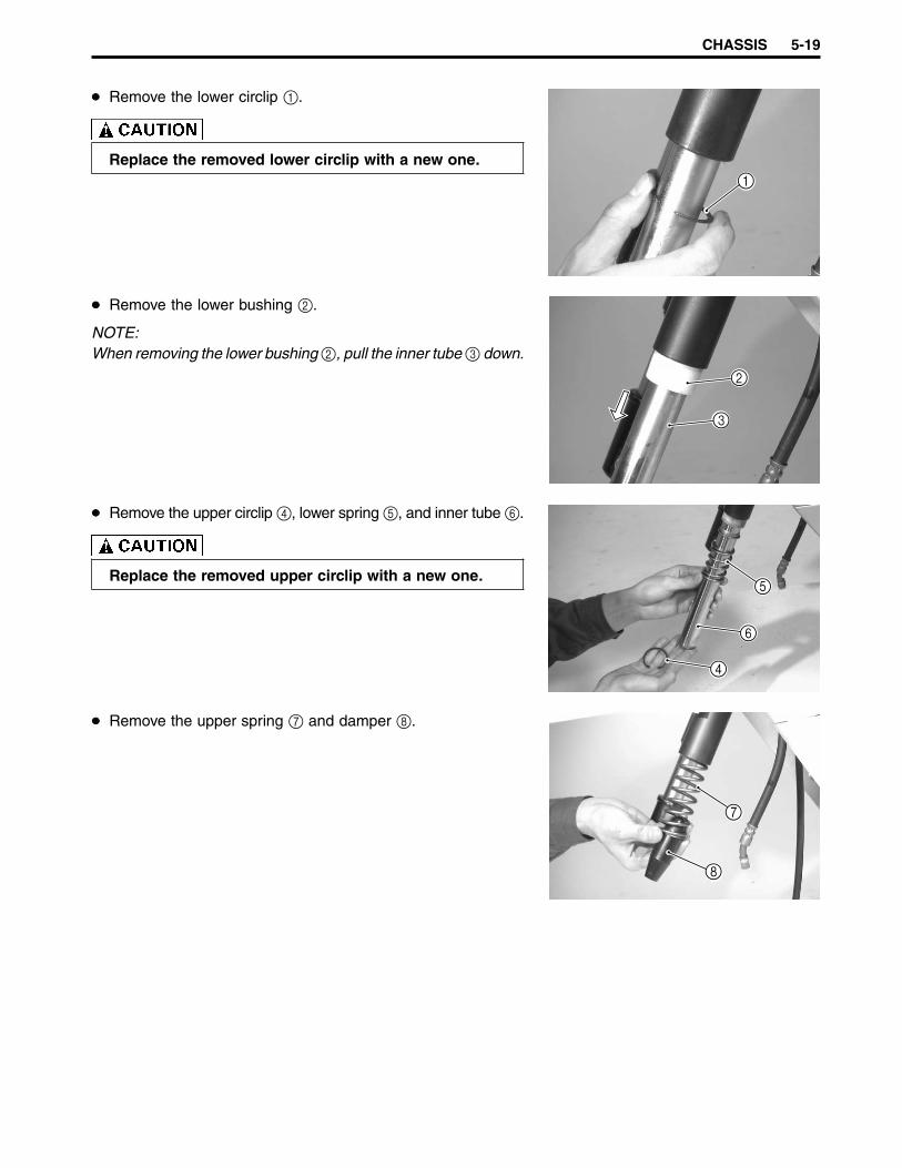
CHASSIS 5-19
Remove the lower circlip 1.
Replace the removed lower circlip with a new one.
Remove the lower bushing 2.
NOTE:When removing the lower bushing 2, pull the inner tube 3 down.
Remove the upper circlip 4, lower spring 5, and inner tube 6.
Replace the removed upper circlip with a new one.
Remove the upper spring 7 and damper 8.
1
2
3
4
6
5
8
7

5-20 CHASSIS
INSPECTIONFORK SPRINGMeasure the fork spring free length. If the fork spring free lengthis shorter than the service limit, replace the fork spring with anew one.
Front fork spring free lengthService Limit: 122 mm
INNER TUBEInspect the inner tube sliding surface for any scuffing or dam-age. If any damages are found, replace the inner tube with anew one.
BUSHINGInspect the bushing for wear or damage. If any damages arefound, replace the bushing with a new one.
REASSEMBLY AND REMOUNTING
Reassemble and remount the front suspension in the reverseorder of removal and disassembly. Pay attention to the followingpoints:
DAMPER AND SPRINGApply SUZUKI SUPER GREASE “A” (15 g) to the damperand springs.
99000-25010: SUZUKI SUPER GREASE “A”
When installing the upper spring 1 and damper 2, facethe smaller diameter end of the upper spring and thehollow end of the damper towards the wheel.
2
1

CHASSIS 5-21
UPPER CIRCLIPInstall the circlip 1 into the groove 2.
Replace the upper circlip with a new one.The rounded side on the circlip must face upward.After installing the upper circlip, make sure that it isproperly seated in the groove.
BUSHINGInstall the lower bushing 3 using the special tool.
09940-52860: Front fork oil seal installer
LOWER CIRCLIPInstall the lower circlip 4 into the ring groove 5.
Replace the lower circlip with a new one.The rounded side on the circlip must face upward.After installing the lower circlip, make sure that it isproperly seated in the groove.
Tighten the brake caliper bracket mounting bolt to the speci-fied torque.
Brake caliper bracket mounting bolt: 20 N·m (2.0 kgf-m)
NOTE:Before tightening the front axle nut, move the front fork up anddown four or five times.
1
2
3
45

5-22 CHASSIS
HANDLEBAR COVERS AND SPEEDOMETER ASSEMBLYCONSTRUCTION
1 Front handlebar cover2 Rear handlebar cover
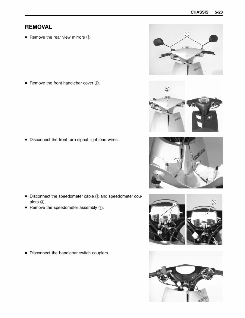
CHASSIS 5-23
REMOVAL
Remove the rear view mirrors 1.
Remove the front handlebar cover 2.
Disconnect the front turn signal light lead wires.
Disconnect the speedometer cable 3 and speedometer cou-plers 4.Remove the speedometer assembly 5.
Disconnect the handlebar switch couplers.
1
2
4
3
5

5-24 CHASSIS
Remove the rear handlebar cover 1.
REMOUNTING
Remount the handlebar covers and the speedometer assemblyin the reverse order of removal.
94P50730
1
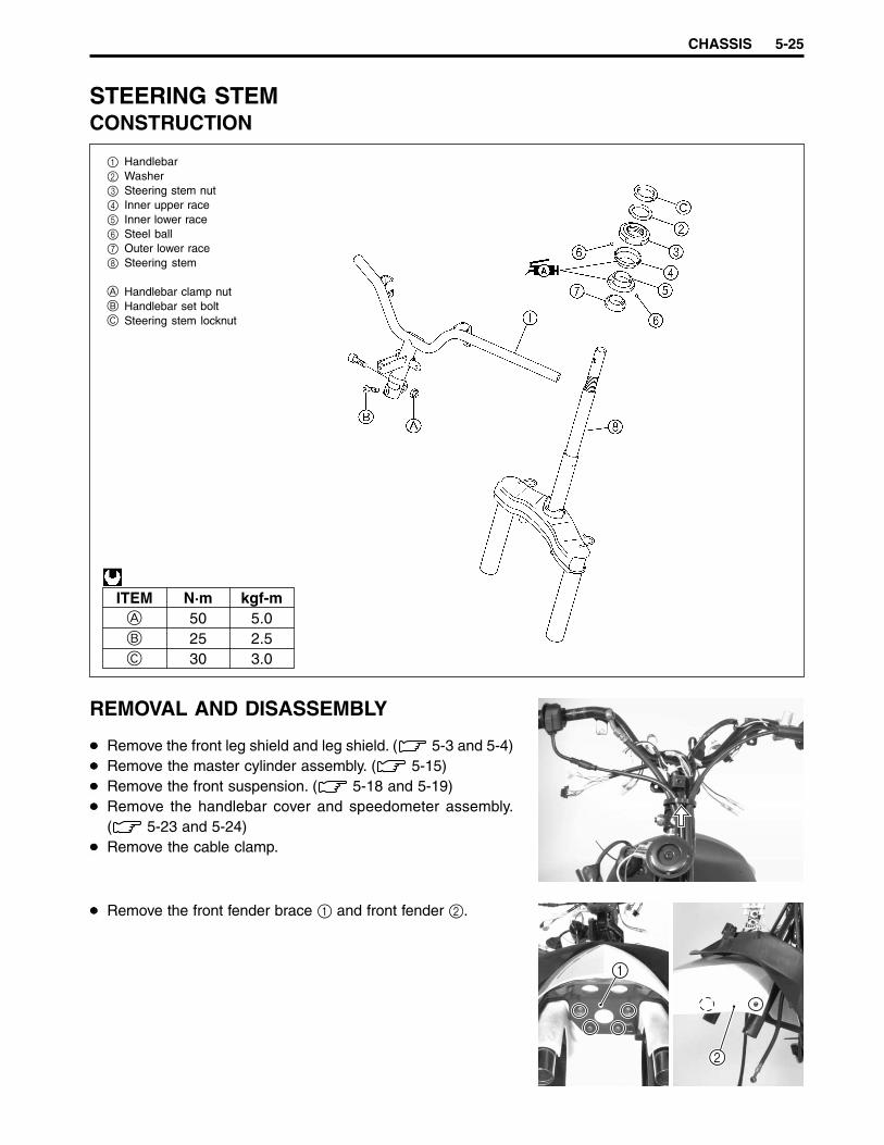
CHASSIS 5-25
STEERING STEMCONSTRUCTION
1 Handlebar2 Washer3 Steering stem nut4 Inner upper race5 Inner lower race6 Steel ball7 Outer lower race8 Steering stem
A Handlebar clamp nutB Handlebar set boltC Steering stem locknut
ITEM N·m kgf-mA 50 5.0B 25 2.5C 30 3.0
REMOVAL AND DISASSEMBLY
Remove the front leg shield and leg shield. ( 5-3 and 5-4)Remove the master cylinder assembly. ( 5-15)Remove the front suspension. ( 5-18 and 5-19)Remove the handlebar cover and speedometer assembly.( 5-23 and 5-24)Remove the cable clamp.
Remove the front fender brace 1 and front fender 2.
1
2

5-26 CHASSIS
Remove the rear brake cable 5.Disconnect the rear brake light switch lead wires 6.
Remove the handlebar.
Remove the steering stem locknut using the special tool.
09910-60611: Universal clamp wrench
Remove the throttle cable 1 and throttle grip 2.
Remove the brake hose 3 and speedometer cable 4.
1
2
3
4
6
5
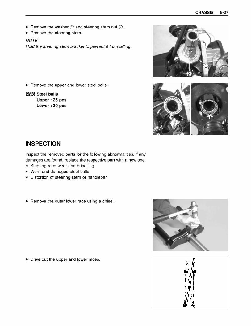
CHASSIS 5-27
Remove the upper and lower steel balls.
Steel ballsUpper : 25 pcsLower : 30 pcs
INSPECTION
Inspect the removed parts for the following abnormalities. If anydamages are found, replace the respective part with a new one.
Steering race wear and brinellingWorn and damaged steel ballsDistortion of steering stem or handlebar
Remove the outer lower race using a chisel.
Drive out the upper and lower races.
Remove the washer 1 and steering stem nut 2.Remove the steering stem.
NOTE:Hold the steering stem bracket to prevent it from falling.
1
2
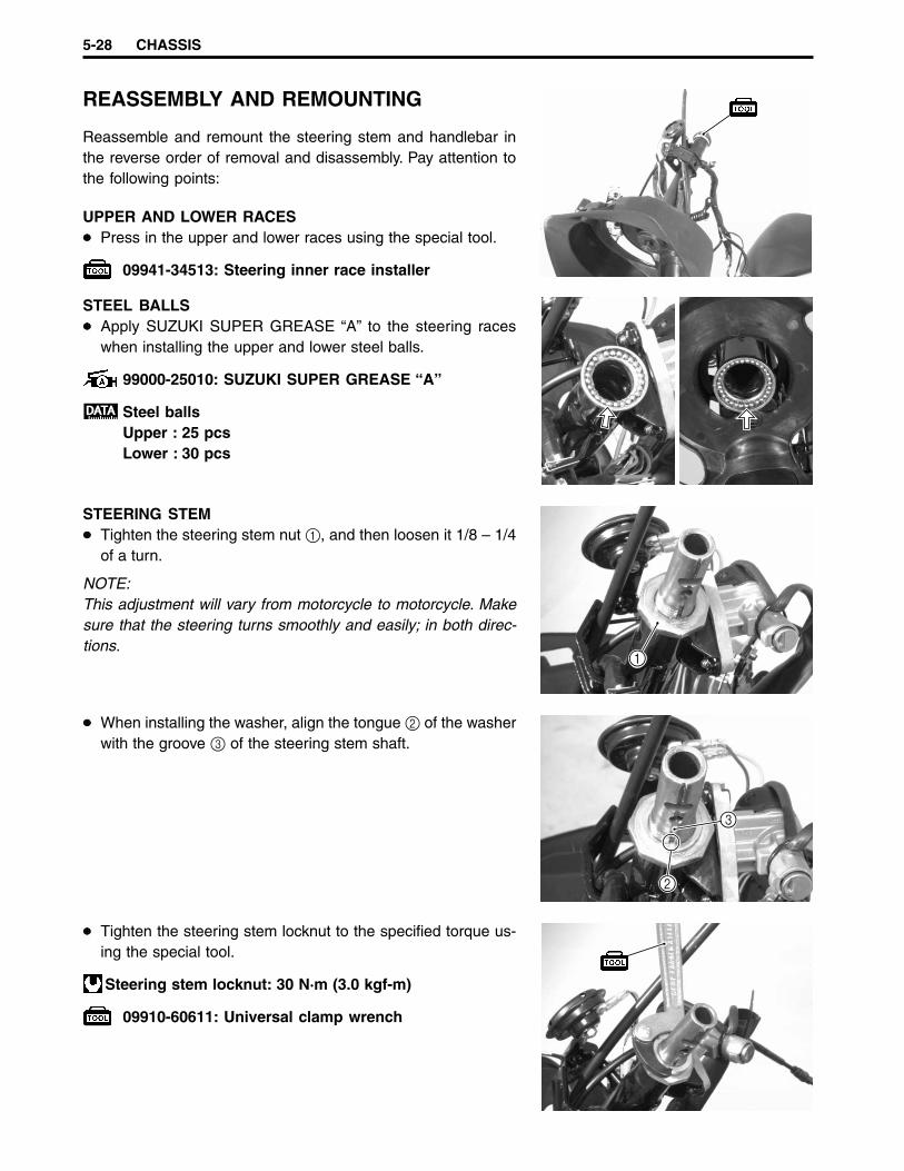
5-28 CHASSIS
STEEL BALLSApply SUZUKI SUPER GREASE “A” to the steering raceswhen installing the upper and lower steel balls.
99000-25010: SUZUKI SUPER GREASE “A”
Steel ballsUpper : 25 pcsLower : 30 pcs
STEERING STEMTighten the steering stem nut 1, and then loosen it 1/8 – 1/4of a turn.
NOTE:This adjustment will vary from motorcycle to motorcycle. Makesure that the steering turns smoothly and easily; in both direc-tions.
When installing the washer, align the tongue 2 of the washerwith the groove 3 of the steering stem shaft.
Tighten the steering stem locknut to the specified torque us-ing the special tool.
Steering stem locknut: 30 N·m (3.0 kgf-m)
09910-60611: Universal clamp wrench
REASSEMBLY AND REMOUNTING
Reassemble and remount the steering stem and handlebar inthe reverse order of removal and disassembly. Pay attention tothe following points:
UPPER AND LOWER RACESPress in the upper and lower races using the special tool.
09941-34513: Steering inner race installer
1
2
3

CHASSIS 5-29
Finger tighten the handlebar set bolt 1 and handlebar clampnut 2, and then tighten them to the specified torque.
Handlebar set bolt: 25 N·m (2.5 kgf-m)Handlebar clamp nut: 50 N·m (5.0 kgf-m)
NOTE:Hold the front fork legs, move them back and forth and makesure that the steering is not loose.
After performing the adjustment and installing thehandlebar, “rock” the front wheel assembly forwardand backward to ensure there is no play and the pro-cedure was accomplished correctly.Check the steering stem to make sure that it movesfreely from left to right with its own weight. If play orstiffness is noticeable, readjust the steering stem nut.
2
1
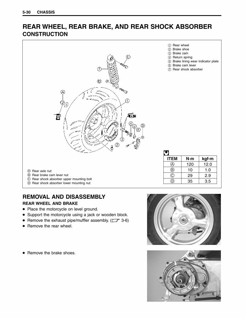
5-30 CHASSIS
REAR WHEEL, REAR BRAKE, AND REAR SHOCK ABSORBERCONSTRUCTION
A Rear axle nutB Rear brake cam lever nutC Rear shock absorber upper mounting boltD Rear shock absorber lower mounting nut
ITEM N·m kgf-mA 120 12.0B 10 1.0C 29 2.9D 35 3.5
1 Rear wheel2 Brake shoe3 Brake cam4 Return spring5 Brake lining wear indicator plate6 Brake cam lever7 Rear shock absorber
REMOVAL AND DISASSEMBLYREAR WHEEL AND BRAKE
Place the motorcycle on level ground.Support the motorcycle using a jack or wooden block.Remove the exhaust pipe/muffler assembly. ( 3-6)Remove the rear wheel.
Remove the brake shoes.

CHASSIS 5-31
REAR SHOCK ABSORBERRemove the frame cover. ( 5-4 and 5-5)Remove the rear shock absorber.
INSPECTIONBRAKE DRUMInspect the brake drum and measure the brake drum I.D. to de-termine the extent of wear. If the measurement exceeds the ser-vice limit, replace the brake drum with a new one. The value ofthis limit is indicated inside the drum.
Brake drum I.D.Service Limit: 120.7 mm
BRAKE SHOEInspect the brake shoes for wear or damage. If any wear or dam-ages are found, replace the brake shoes as a set.
Replace the brake shoes as a set, otherwise brakingperformance will be adversely affected.
REAR SHOCK ABSORBERInspect the rear shock absorber for oil leakage or other damage.If any oil leakages or damages are found, replace the rear shockabsorber with a new one.
Do not attempt to disassemble the shock absorber. Itis not serviceable.
TIRE ........................................................................... 2-12
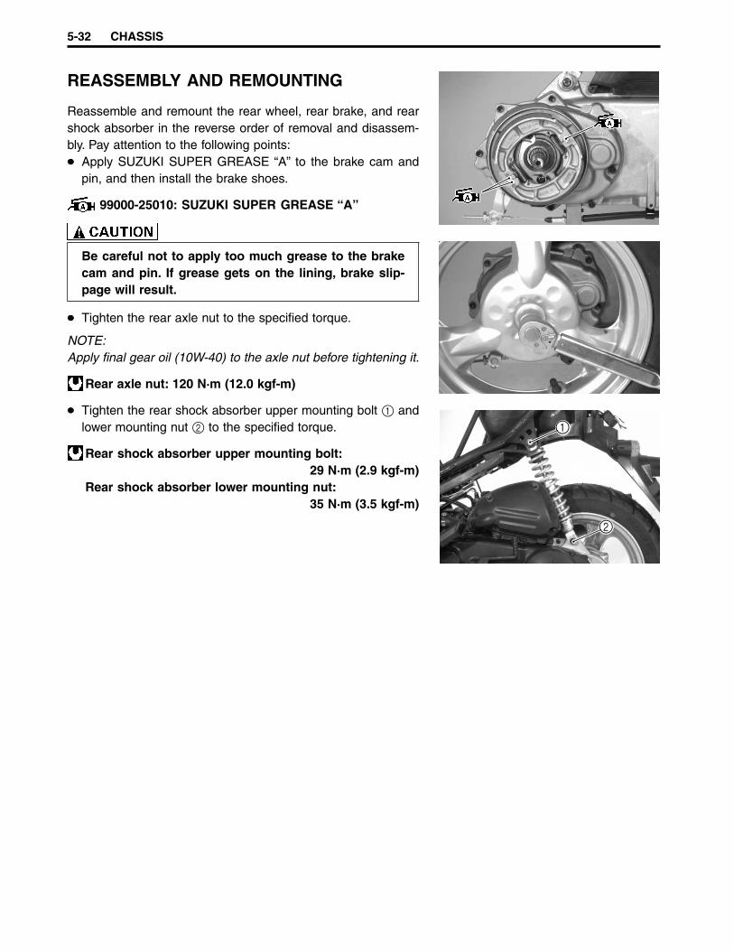
5-32 CHASSIS
REASSEMBLY AND REMOUNTING
Reassemble and remount the rear wheel, rear brake, and rearshock absorber in the reverse order of removal and disassem-bly. Pay attention to the following points:
Apply SUZUKI SUPER GREASE “A” to the brake cam andpin, and then install the brake shoes.
99000-25010: SUZUKI SUPER GREASE “A”
Be careful not to apply too much grease to the brakecam and pin. If grease gets on the lining, brake slip-page will result.
Tighten the rear axle nut to the specified torque.
NOTE:Apply final gear oil (10W-40) to the axle nut before tightening it.
Rear axle nut: 120 N·m (12.0 kgf-m)
Tighten the rear shock absorber upper mounting bolt 1 andlower mounting nut 2 to the specified torque.
Rear shock absorber upper mounting bolt:29 N·m (2.9 kgf-m)
Rear shock absorber lower mounting nut:35 N·m (3.5 kgf-m)
1
2

CHASSIS 5-33
TIRES AND WHEELSTIRE REMOVAL
The most critical factor of a tubeless tire is the seal between thewheel rim and the tire bead. Because of this, we recommendedusing a tire changer that can satisfy this sealing requirementand can make the operation efficient as well as functional.For operating procedures, refer to the instructions supplied bythe tire changer manufacturer.
NOTE:When removing a tire for repair or inspection, be sure to markthe tire with chalk to indicate the tire position relative to thevalve position.Even though the tire is refitted to the original position afterrepairing the puncture, the tire may have to be balanced againsince such a repair can cause imbalance.
INSPECTIONWHEELSClean and check each wheel for the following. If any item is ob-served, replace the wheel with a new one.
Distortion and crackNick or scratch on beadWheel rim runout
Wheel rim runout (axial and radial)Service Limit: 2.0 mm
TIRESCheck each tire for the following. If any item is observed, replacethe tire with a new one.
Nicks and rupture on sidewallTread remaining depthSeparation of cordAbnormal, uneven wear on treadSurface damage on beadLocalized tread wear due to skidding (flat spot)Abnormal condition of inner liner
09900-20805: Tire depth gauge
Tire tread depth (front and rear)Service Limit: 1.6 mm

5-34 CHASSIS
VALVEInspect the valve 1 for damage.If the seal rubber is peeling or damaged, replace the valve witha new one.
NOTE:If the external appearance of the valve shows no abnormal con-dition, removing the valve is not necessary.
Inspect the valve core seal 2 for deformation or damage.If the valve core seal has abnormal deformation, replace thevalve with a new one.
INSTALLATIONVALVE
Clean any dust or rust around the valve hole 1.Install the valve in the rim.
NOTE:To properly install the valve 2 into the valve hole, apply a spe-cial tire lubricant or neutral soapy liquid to the valve.
Be careful not to damage the valve lip A.
B Wheel

CHASSIS 5-35
TIREApply a special tire lubricant to the tire bead.When installing the tire, make sure the arrow 1 faces thedirection of wheel rotation and align the balancing.
Replace the removed valve with a new one.
The tire is designed to have specified rotational direction.
Never apply oil, grease, or gasoline to the tire bead.
When installing the tire, make sure that the arrow 1 faces thedirection of wheel rotation and align the balancing mark 2 onthe tire with the valve 3 as shown.
For installing the tire onto the wheel, refer to the instructionsgiven by the tire changer manufacturer.Bounce the tire several times while rotating it. This will allowthe tire bead to expand outwards, making inflation easier.
NOTE:Before inflating the tire, make sure that the balance mark isaligned with the valve stem.
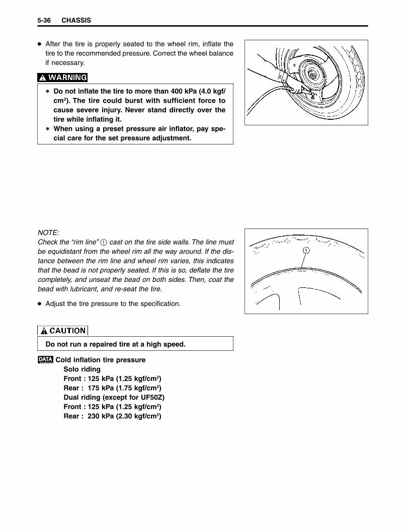
5-36 CHASSIS
After the tire is properly seated to the wheel rim, inflate thetire to the recommended pressure. Correct the wheel balanceif necessary.
Do not inflate the tire to more than 400 kPa (4.0 kgf/cm2). The tire could burst with sufficient force tocause severe injury. Never stand directly over thetire while inflating it.When using a preset pressure air inflator, pay spe-cial care for the set pressure adjustment.
NOTE:Check the “rim line” 1 cast on the tire side walls. The line mustbe equidistant from the wheel rim all the way around. If the dis-tance between the rim line and wheel rim varies, this indicatesthat the bead is not properly seated. If this is so, deflate the tirecompletely, and unseat the bead on both sides. Then, coat thebead with lubricant, and re-seat the tire.
Adjust the tire pressure to the specification.
Do not run a repaired tire at a high speed.
Cold inflation tire pressureSolo ridingFront : 125 kPa (1.25 kgf/cm2)Rear : 175 kPa (1.75 kgf/cm2)Dual riding (except for UF50Z)Front : 125 kPa (1.25 kgf/cm2)Rear : 230 kPa (2.30 kgf/cm2)

ELECTRICAL SYSTEM 6-1
ELECTRICAL SYSTEM
CONTENTS
CAUTIONS IN SERVICING ........................................................................................................................... 6- 2CONNECTOR .......................................................................................................................................... 6- 2COUPLER ................................................................................................................................................ 6- 2CLAMPS .................................................................................................................................................. 6- 2FUSE ........................................................................................................................................................ 6- 2SEMICONDUCTOR EQUIPPED PARTS ................................................................................................ 6- 2CONNECTING THE BATTERY ............................................................................................................... 6- 3WIRING PROCEDURE ............................................................................................................................ 6- 3USING THE MULTI CIRCUIT TESTER ................................................................................................... 6- 3
LOCATION OF ELECTRICAL COMPONENTS ........................................................................................... 6- 4CHARGING AND LIGHTING SYSTEM ........................................................................................................ 6- 6
DESCRIPTION ......................................................................................................................................... 6- 6TROUBLESHOOTING ............................................................................................................................. 6- 7INSPECTION ........................................................................................................................................... 6- 8
STARTER SYSTEM.......................................................................................................................................6-10DESCRIPTION .........................................................................................................................................6-10TROUBLESHOOTING .............................................................................................................................6-10STARTER MOTOR REMOVAL AND DISASSEMBLY ............................................................................ 6-11STARTER MOTOR INSPECTION ...........................................................................................................6-12STARTER MOTOR REASSEMBLY ........................................................................................................6-13STARTER RELAY INSPECTION ............................................................................................................6-13
IGNITION SYSTEM .......................................................................................................................................6-14DESCRIPTION .........................................................................................................................................6-14TROUBLESHOOTING .............................................................................................................................6-14INSPECTION ...........................................................................................................................................6-16
FUEL LEVEL INDICATOR SWITCH .............................................................................................................6-19INSPECTION ...........................................................................................................................................6-19
OIL LEVEL INDICATOR SWITCH ................................................................................................................6-20INSPECTION ...........................................................................................................................................6-20
THERMOELEMENT, CARBURETOR HEATER,AND THERMOSWITCH.................................................................................................................................6-21
INSPECTION ...........................................................................................................................................6-21SPEEDOMETER ...........................................................................................................................................6-23
REMOVAL AND DISASSEMBLY ............................................................................................................6-23INSPECTION ...........................................................................................................................................6-23
LAMPS ...........................................................................................................................................................6-24HEADLIGHT ............................................................................................................................................6-24FRONT AND REAR TURN SIGNAL LIGHT ........................................................................................... 6-25BRAKE LIGHT/TAILLIGHT .....................................................................................................................6-26LICENSE PLATE LIGHT .........................................................................................................................6-27
RELAYS .........................................................................................................................................................6-28STARTER RELAY ....................................................................................................................................6-28TURN SIGNAL RELAY ............................................................................................................................6-28
SWITCHES ....................................................................................................................................................6-29BATTERY .......................................................................................................................................................6-30
REMOVAL ................................................................................................................................................6-30REMOUNTING .........................................................................................................................................6-30SPECIFICATIONS ...................................................................................................................................6-31INITIAL CHARGING ................................................................................................................................6-31SERVICING ..............................................................................................................................................6-32RECHARGING OPERATION ..................................................................................................................6-32SERVICE LIFE .........................................................................................................................................6-33
6
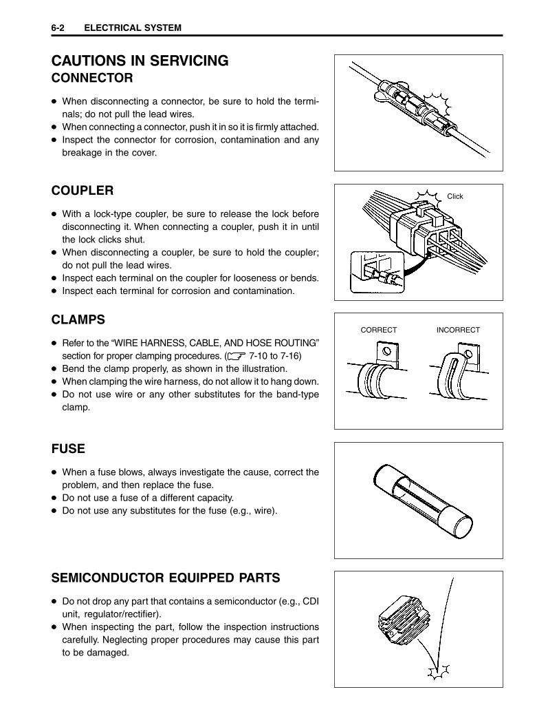
6-2 ELECTRICAL SYSTEM
CAUTIONS IN SERVICINGCONNECTOR
When disconnecting a connector, be sure to hold the termi-nals; do not pull the lead wires.When connecting a connector, push it in so it is firmly attached.Inspect the connector for corrosion, contamination and anybreakage in the cover.
COUPLER
With a lock-type coupler, be sure to release the lock beforedisconnecting it. When connecting a coupler, push it in untilthe lock clicks shut.When disconnecting a coupler, be sure to hold the coupler;do not pull the lead wires.Inspect each terminal on the coupler for looseness or bends.Inspect each terminal for corrosion and contamination.
CLAMPS
Refer to the “WIRE HARNESS, CABLE, AND HOSE ROUTING”section for proper clamping procedures. ( 7-10 to 7-16)Bend the clamp properly, as shown in the illustration.When clamping the wire harness, do not allow it to hang down.Do not use wire or any other substitutes for the band-typeclamp.
FUSE
When a fuse blows, always investigate the cause, correct theproblem, and then replace the fuse.Do not use a fuse of a different capacity.Do not use any substitutes for the fuse (e.g., wire).
SEMICONDUCTOR EQUIPPED PARTS
Do not drop any part that contains a semiconductor (e.g., CDIunit, regulator/rectifier).When inspecting the part, follow the inspection instructionscarefully. Neglecting proper procedures may cause this partto be damaged.
Click
CORRECT INCORRECT
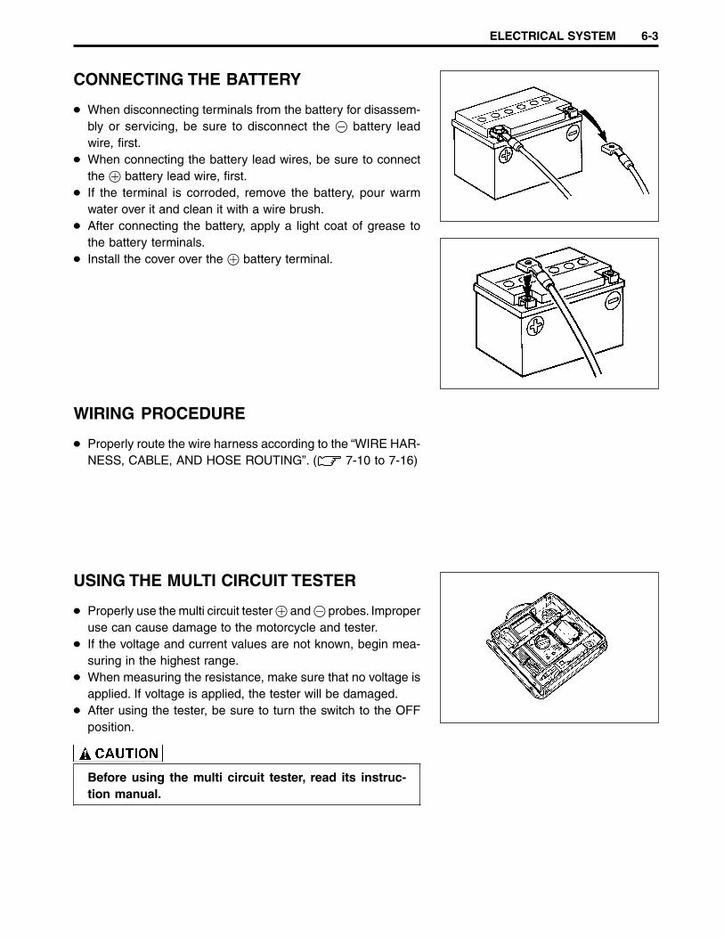
ELECTRICAL SYSTEM 6-3
CONNECTING THE BATTERY
When disconnecting terminals from the battery for disassem-bly or servicing, be sure to disconnect the - battery leadwire, first.When connecting the battery lead wires, be sure to connectthe + battery lead wire, first.If the terminal is corroded, remove the battery, pour warmwater over it and clean it with a wire brush.After connecting the battery, apply a light coat of grease tothe battery terminals.Install the cover over the + battery terminal.
WIRING PROCEDURE
Properly route the wire harness according to the “WIRE HAR-NESS, CABLE, AND HOSE ROUTING”. ( 7-10 to 7-16)
USING THE MULTI CIRCUIT TESTER
Properly use the multi circuit tester + and - probes. Improperuse can cause damage to the motorcycle and tester.If the voltage and current values are not known, begin mea-suring in the highest range.When measuring the resistance, make sure that no voltage isapplied. If voltage is applied, the tester will be damaged.After using the tester, be sure to turn the switch to the OFFposition.
Before using the multi circuit tester, read its instruc-tion manual.

6-4 ELECTRICAL SYSTEM
LOCATION OF ELECTRICAL COMPONENTS
1 Fuel level indicator switch2 Thermoswitch3 Oil level indicator switch4 CDI unit5 Right handlebar switch6 Horn7 Turn signal relay8 Resistor9 Regulator/rectifier0 GeneratorA Starter motor
2
1
3 4
5
6
97
8
0
A

ELECTRICAL SYSTEM 6-5
B Left handlebar switchC Ignition switchD ThermoelementE Carburetor heaterF BatteryG FuseH Starter relayI Ignition coil
B
C D
E
G
H
F
I

6-6 ELECTRICAL SYSTEM
CHARGING AND LIGHTING SYSTEMDESCRIPTION
The charging system for this motorcycle uses a generator, as shown below. The charging and lighting coilsare mounted on the generator stator and generate AC current as the generator rotor turns. The AC current,which is generated in the charging coil, is converted by the regulator/rectifier into DC current. The DCcurrent then charges the battery and the lighting coil uses the regulated AC current to supply the meter light,headlight, and license plate light.
W/R
Y/W
Y/W
R
B/W
Y/W
Regulator/rectifier
Lighting switch
Generator
Meter lightHeadlight Taillight License platelight
Fuse
Battery
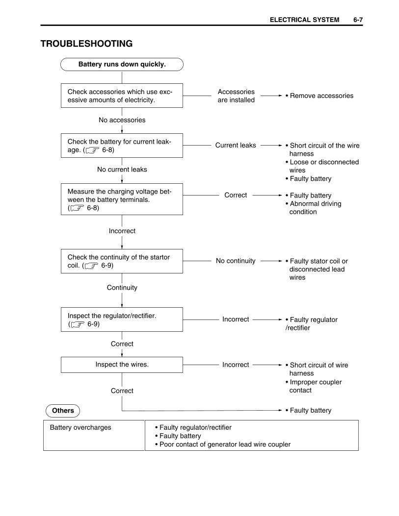
ELECTRICAL SYSTEM 6-7
TROUBLESHOOTING
• Remove accessoriesAccessoriesare installed
Battery runs down quickly.
Others
No accessories
• Short circuit of the wire harness• Loose or disconnected wires• Faulty battery
Current leaks
Correct
No continuity
Incorrect
Incorrect
Check the battery for current leak-age.
No current leaks
• Faulty battery• Abnormal driving condition
Measure the charging voltage bet-ween the battery terminals.( 6-8)
Incorrect
• Faulty stator coil or disconnected lead wires
Check the continuity of the startorcoil.
Continuity
• Faulty regulator/rectifier
Inspect the regulator/rectifier.
Correct
• Short circuit of wire harness• Improper coupler contact
• Faulty battery
Inspect the wires.
Battery overcharges
Correct
( 6-8)
( 6-9)
( 6-9)
• Faulty regulator/rectifier• Faulty battery• Poor contact of generator lead wire coupler
Check accessories which use exc-essive amounts of electricity.
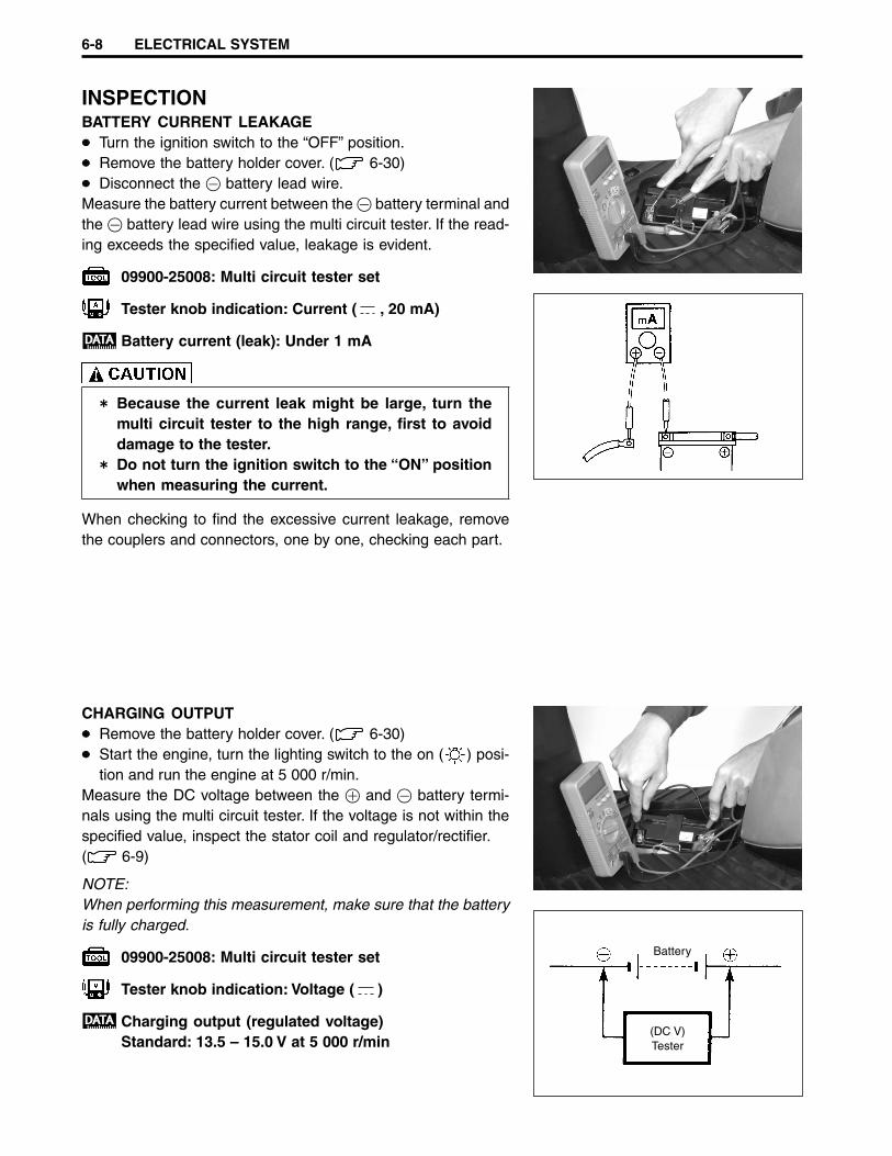
6-8 ELECTRICAL SYSTEM
INSPECTIONBATTERY CURRENT LEAKAGE
Turn the ignition switch to the “OFF” position.Remove the battery holder cover. ( 6-30)Disconnect the - battery lead wire.
Measure the battery current between the - battery terminal andthe - battery lead wire using the multi circuit tester. If the read-ing exceeds the specified value, leakage is evident.
09900-25008: Multi circuit tester set
Tester knob indication: Current ( , 20 mA)
Battery current (leak): Under 1 mA
Because the current leak might be large, turn themulti circuit tester to the high range, first to avoiddamage to the tester.Do not turn the ignition switch to the “ON” positionwhen measuring the current.
When checking to find the excessive current leakage, removethe couplers and connectors, one by one, checking each part.
CHARGING OUTPUTRemove the battery holder cover. ( 6-30)Start the engine, turn the lighting switch to the on ( ) posi-tion and run the engine at 5 000 r/min.
Measure the DC voltage between the + and - battery termi-nals using the multi circuit tester. If the voltage is not within thespecified value, inspect the stator coil and regulator/rectifier.( 6-9)
NOTE:When performing this measurement, make sure that the batteryis fully charged.
09900-25008: Multi circuit tester set
Tester knob indication: Voltage ( )
Charging output (regulated voltage)Standard: 13.5 – 15.0 V at 5 000 r/min
Battery
(DC V)Tester

ELECTRICAL SYSTEM 6-9
STATOR COIL RESISTANCERemove the trunk. ( 5-4)Disconnect the generator coupler 1.
Measure the resistance between the lead wires using the multicircuit tester. If the resistance is not within the specified value,replace the stator coil with a new one.
09900-25008: Multi circuit tester set
Tester knob indication: Resistance (ΩΩΩΩΩ)
Stator coil resistanceStandard: 0.5 – 2.0 ΩΩΩΩΩ (White/Red – Ground)
0.3 – 1.5 ΩΩΩΩΩ (Yellow/White – Ground)
REGULATOR/RECTIFIERRemove the front leg shield. ( 5-3)Disconnect the regulator/rectifier coupler 1.
Measure the voltage between the terminals using the multi cir-cuit tester, as indicated in the table below. If voltage is not withinthe specified value, replace the regulator/rectifier with a new one.
09900-25008: Multi circuit tester set
Tester knob indication: Diode test ( )
Unit: V+ Tester probe
- T
este
r pr
obe A B C D
A 1.4 – 1.5 1.4 – 1.5 1.4 – 1.5
B 0.5 – 1.4 1.4 – 1.5 1.4 – 1.5
C 1.4 – 1.5 1.4 – 1.5 0.6 – 1.5
D 1.4 – 1.5 1.4 – 1.5 0.6 – 1.5
NOTE:If the tester reads under 1.4 V, disconnect the tester probes fromthe wire leads, and then replace the multi circuit tester’s battery.
W/R
ΩΩ
Y/W
D A
BC
1
1
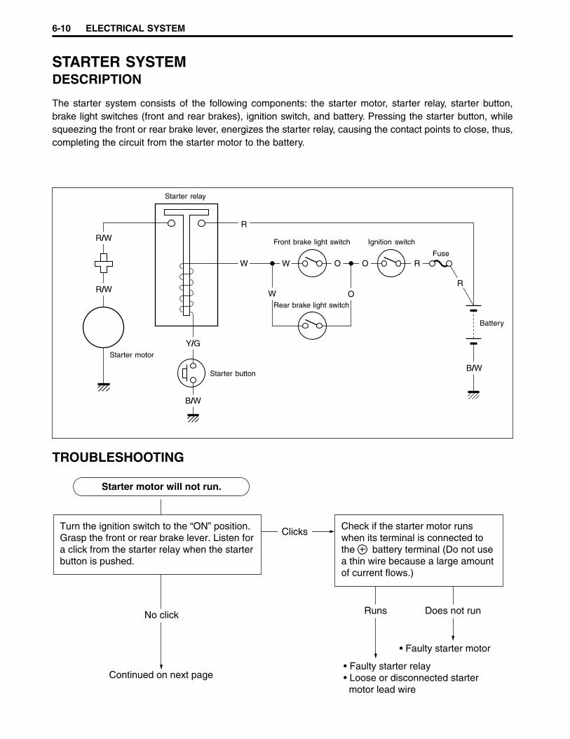
6-10 ELECTRICAL SYSTEM
STARTER SYSTEMDESCRIPTION
The starter system consists of the following components: the starter motor, starter relay, starter button,brake light switches (front and rear brakes), ignition switch, and battery. Pressing the starter button, whilesqueezing the front or rear brake lever, energizes the starter relay, causing the contact points to close, thus,completing the circuit from the starter motor to the battery.
TROUBLESHOOTING
W
Y/G
B/W
R/W
R
W
R/W O
W O O R
R
B/W
Turn the ignition switch to the “ON” position. Grasp the front or rear brake lever. Listen fora click from the starter relay when the starter button is pushed.
Check if the starter motor runswhen its terminal is connected tothe battery terminal (Do not usea thin wire because a large amountof current flows.)
Starter motor will not run.
No click
Clicks
• Faulty starter motor
Continued on next page
Does not run
• Faulty starter relay• Loose or disconnected starter motor lead wire
Runs
Starter button
Front brake light switch Ignition switch
Rear brake light switch
Starter motor
Starter relay
Fuse
Battery

ELECTRICAL SYSTEM 6-11
STARTER MOTOR REMOVAL ANDDISASSEMBLY
Disconnect the starter motor lead wire and remove the startermotor 1.
Others
Engine does not turn though thestarter motor runs.
• Faulty starter pinion gear assembly
No voltage
Incorrect
• Faulty ignition switch• Faulty starter button• Faulty brake light switches (front and rear brakes)• Improper connector contact
Measure the starter relay voltage at the starterrelay connectors (between W and Y/G )when the starter button is pushed.
Voltage
• Faulty starter relay
• Improper starter relay contact
Inspect the starter relay.
Correct
( 6-13)
• Open circuit in wire harness
1

6-12 ELECTRICAL SYSTEM
Disassemble the starter motor, as shown.
STARTER MOTOR INSPECTIONCARBON BRUSHESInspect the carbon brushes for abnormal wear, cracks, or smooth-ness in the brush holder. If any damages are found, replace thebrush assembly with a new one.
COMMUTATORInspect the commutator for discoloration, abnormal wear, or un-dercut A. If any damages are found, replace the armature witha new one.If the commutator surface is discolored, polish it with #400 sand-paper and wipe it using a clean, dry cloth.If there is no undercut, scrape out the insulator 1 with a sawblade.
ARMATURE COILCheck for continuity between each segment and the armatureshaft using the multi circuit tester. If there is no continuity be-tween the segments or there is continuity between the segmentsand shaft, replace the armature with a new one.
09900-25008: Multi circuit tester set
Tester knob indication: Continuity test ( )
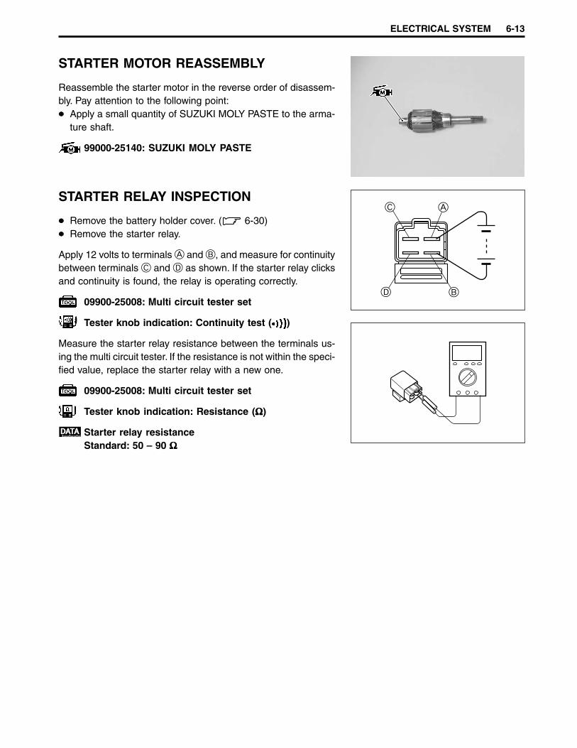
ELECTRICAL SYSTEM 6-13
STARTER MOTOR REASSEMBLY
Reassemble the starter motor in the reverse order of disassem-bly. Pay attention to the following point:
Apply a small quantity of SUZUKI MOLY PASTE to the arma-ture shaft.
99000-25140: SUZUKI MOLY PASTE
STARTER RELAY INSPECTION
Remove the battery holder cover. ( 6-30)Remove the starter relay.
Apply 12 volts to terminals A and B, and measure for continuitybetween terminals C and D as shown. If the starter relay clicksand continuity is found, the relay is operating correctly.
09900-25008: Multi circuit tester set
Tester knob indication: Continuity test ( )
Measure the starter relay resistance between the terminals us-ing the multi circuit tester. If the resistance is not within the speci-fied value, replace the starter relay with a new one.
09900-25008: Multi circuit tester set
Tester knob indication: Resistance (ΩΩΩΩΩ)
Starter relay resistanceStandard: 50 – 90 ΩΩΩΩΩ
D B
AC

6-14 ELECTRICAL SYSTEM
IGNITION SYSTEMDESCRIPTION
In the capacitor discharged ignition system, the battery’s electrical energy charges the capacitor. This en-ergy is released in a single surge at the specified ignition timing point and the current flows through theprimary side of the ignition coil. A high voltage is induced in the secondary windings of the ignition coil,resulting in a strong spark between the spark plug gap.
TROUBLESHOOTING
W/R Br
W
Y/W
R
R O
B/W
W/Bl
B/W
B/W
B/W
Battery
Generator
Regulator/rectifier
CDI unit
Ignition coil
SparkPlug
Check the ignition system couplers for poorconnections.
No spark or poor spark
Correct
Correct
Looseness
Continued on next page
• Improper coupler connection
Measure the battery voltage between inputlead wires (O and B/W) at the CDI unitwith the ignition switch in the “ON” position.
Incorrect • Faulty ignition switch• Broken wire harness or poor connection of related circuit couplers
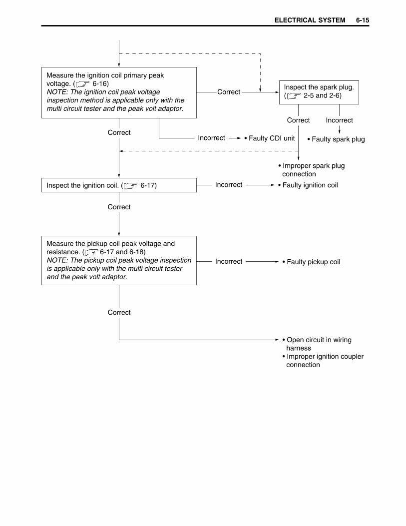
ELECTRICAL SYSTEM 6-15
Correct
Incorrect
Measure the ignition coil primary peakvoltage. NOTE: The ignition coil peak voltageinspection method is applicable only with themulti circuit tester and the peak volt adaptor.
• Faulty pickup coil
Incorrect • Faulty CDI unitIncorrect
Incorrect • Faulty ignition coil
• Open circuit in wiring harness• Improper ignition coupler connection
Inspect the ignition coil.
Correct
Correct
Correct
Inspect the spark plug.
• Faulty spark plug
Incorrect
• Improper spark plug connection
Correct
( 2-5 and 2-6)
( 6-16)
( 6-17)
Measure the pickup coil peak voltage and resistance. ( 6-17 and 6-18)NOTE: The pickup coil peak voltage inspection is applicable only with the multi circuit tester and the peak volt adaptor.
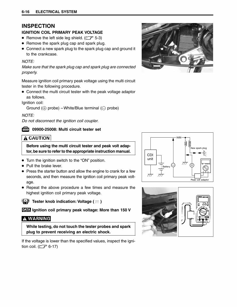
6-16 ELECTRICAL SYSTEM
W/Bl
CDIunit
Battery
Peak volt adaptor
New spark plug
INSPECTIONIGNITION COIL PRIMARY PEAK VOLTAGE
Remove the left side leg shield. ( 5-3)Remove the spark plug cap and spark plug.Connect a new spark plug to the spark plug cap and ground itto the crankcase.
NOTE:Make sure that the spark plug cap and spark plug are connectedproperly.
Measure ignition coil primary peak voltage using the multi circuittester in the following procedure.
Connect the multi circuit tester with the peak voltage adaptoras follows.
Ignition coil:Ground (+ probe) – White/Blue terminal (- probe)
NOTE:Do not disconnect the ignition coil coupler.
09900-25008: Multi circuit tester set
Before using the multi circuit tester and peak volt adap-tor, be sure to refer to the appropriate instruction manual.
Turn the ignition switch to the “ON” position.Pull the brake lever.Press the starter button and allow the engine to crank for a fewseconds, and then measure the ignition coil primary peak volt-age.Repeat the above procedure a few times and measure thehighest ignition coil primary peak voltage.
Tester knob indication: Voltage ( )
Ignition coil primary peak voltage: More than 150 V
While testing, do not touch the tester probes and sparkplug to prevent receiving an electric shock.
If the voltage is lower than the specified values, inspect the igni-tion coil. ( 6-17)

ELECTRICAL SYSTEM 6-17
IGNITION COIL RESISTANCERemove the footboard. ( 5-3)Disconnect the ignition coil coupler 1.
Measure the ignition coil resistance in both the primary and sec-ondary windings using the multi circuit tester. If the resistance inboth the primary and secondary windings is close to the speci-fied values, the windings are in sound condition.
09900-25008: Multi circuit tester set
Tester knob indication: Resistance (ΩΩΩΩΩ)
Ignition coil resistancePrimary: 0.2 – 1.5 ΩΩΩΩΩ (W/Bl – B/W)Secondary: 10 – 20 kΩΩΩΩΩ (B/W – spark plug cap)
PICKUP COIL PEAK VOLTAGERemove the trunk. ( 5-4)
NOTE:Make sure that all of the couplers are connected properly andthe battery is fully charged.
Disconnect the CDI unit coil coupler 1.Measure the pickup coil peak voltage in the following procedure.
Connect the multi circuit tester with the peak volt adaptor asfollows.
Brown (- Probe) – White (+ Probe)
09900-25008: Multi circuit tester set
Before using the multi circuit tester and peak volt adap-tor, be sure to read the appropriate instruction manual.
Turn the ignition switch to the “ON” position.Measure the pickup coil peak voltage while squeezing the frontor rear brake lever and pressing the starter button to turn theengine for a few seconds.
Repeat the above procedure a few times and measure thehighest pickup coil peak voltage.
Tester knob indication: Voltage ( )
Pickup coil peak voltage: More than 5.0 V
If the peak voltage measured on the CDI unit coupler is lowerthan the standard value, measure the peak voltage on the pickupcoil coupler as follows.
+W
BrBr
W
Y/W
W/R
-
Gererator
Peak voltadaptor
1
1
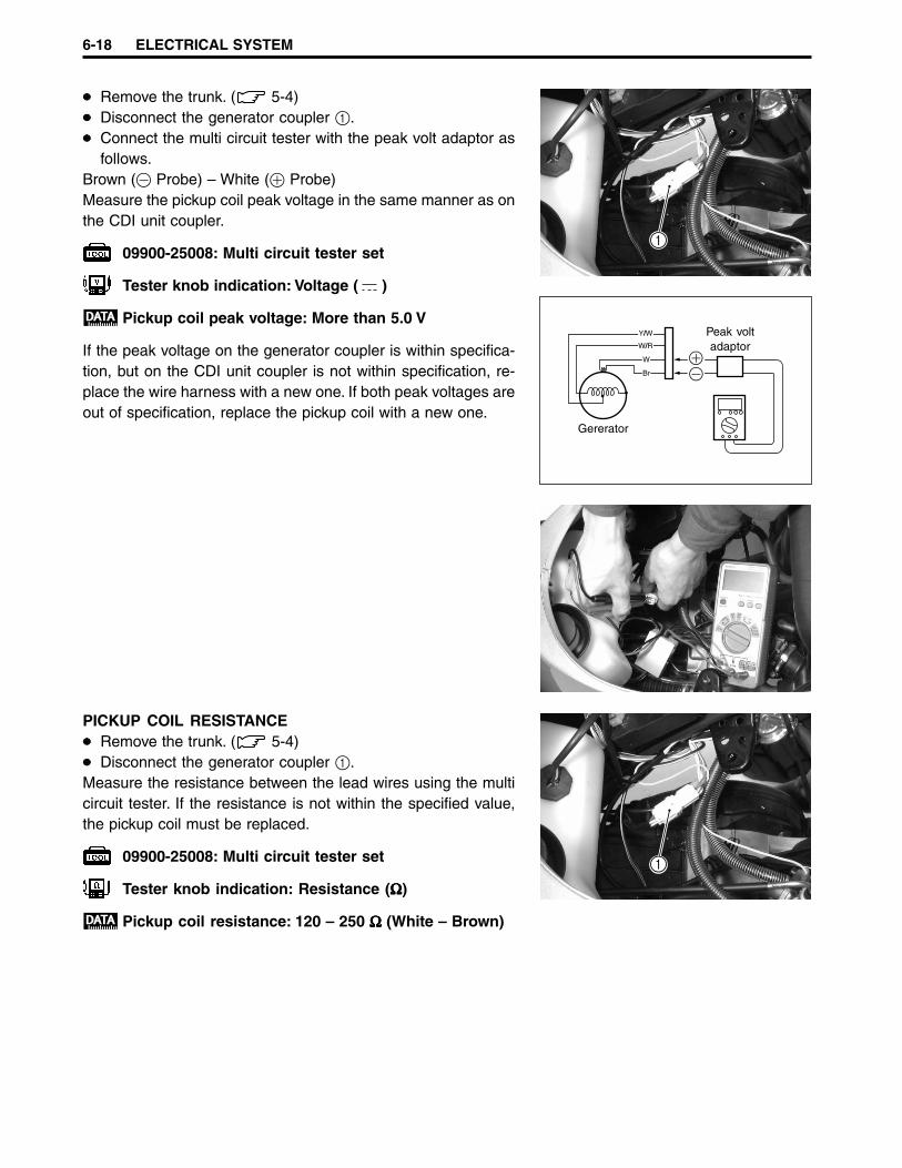
6-18 ELECTRICAL SYSTEM
Remove the trunk. ( 5-4)Disconnect the generator coupler 1.Connect the multi circuit tester with the peak volt adaptor asfollows.
Brown (- Probe) – White (+ Probe)Measure the pickup coil peak voltage in the same manner as onthe CDI unit coupler.
09900-25008: Multi circuit tester set
Tester knob indication: Voltage ( )
Pickup coil peak voltage: More than 5.0 V
If the peak voltage on the generator coupler is within specifica-tion, but on the CDI unit coupler is not within specification, re-place the wire harness with a new one. If both peak voltages areout of specification, replace the pickup coil with a new one.
+
Y/W
W/R
Br
W
-
Gererator
Peak voltadaptor
1
PICKUP COIL RESISTANCERemove the trunk. ( 5-4)Disconnect the generator coupler 1.
Measure the resistance between the lead wires using the multicircuit tester. If the resistance is not within the specified value,the pickup coil must be replaced.
09900-25008: Multi circuit tester set
Tester knob indication: Resistance (ΩΩΩΩΩ)
Pickup coil resistance: 120 – 250 ΩΩΩΩΩ (White – Brown)
1
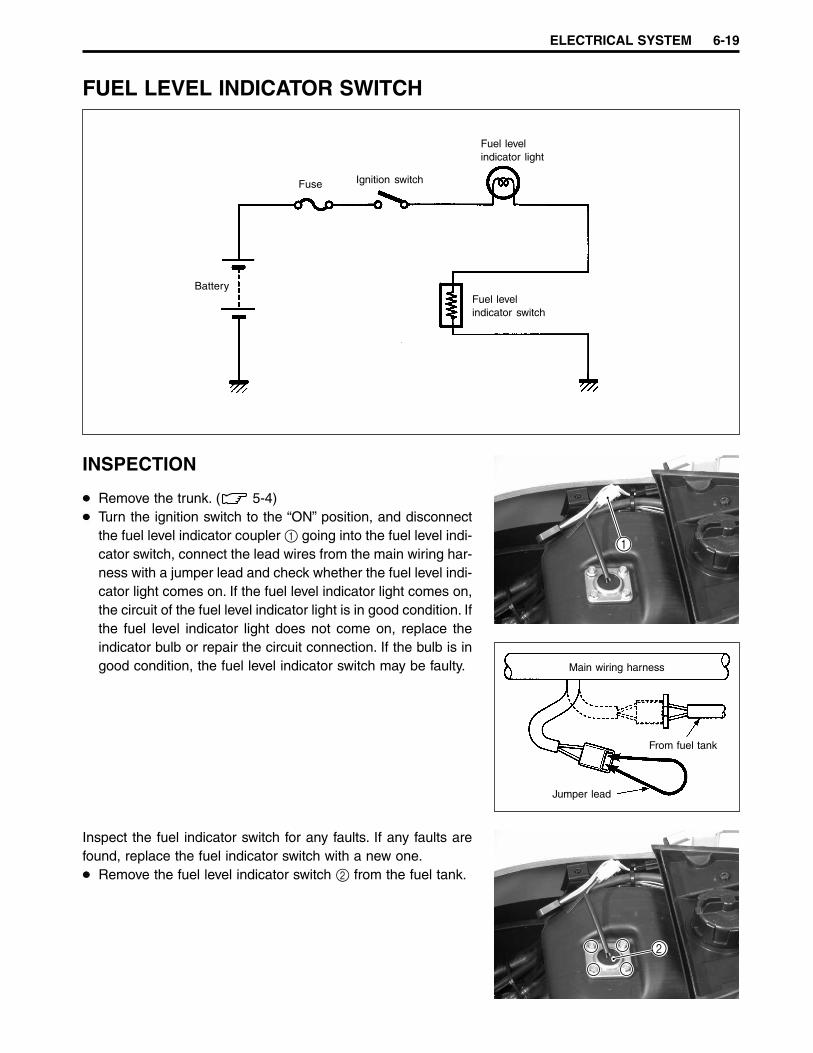
ELECTRICAL SYSTEM 6-19
FUEL LEVEL INDICATOR SWITCH
INSPECTION
Remove the trunk. ( 5-4)Turn the ignition switch to the “ON” position, and disconnectthe fuel level indicator coupler 1 going into the fuel level indi-cator switch, connect the lead wires from the main wiring har-ness with a jumper lead and check whether the fuel level indi-cator light comes on. If the fuel level indicator light comes on,the circuit of the fuel level indicator light is in good condition. Ifthe fuel level indicator light does not come on, replace theindicator bulb or repair the circuit connection. If the bulb is ingood condition, the fuel level indicator switch may be faulty.
Inspect the fuel indicator switch for any faults. If any faults arefound, replace the fuel indicator switch with a new one.
Remove the fuel level indicator switch 2 from the fuel tank.
Fuse Ignition switch
Battery
Fuel levelindicator light
Fuel levelindicator switch
Main wiring harness
From fuel tank
Jumper lead
1
2
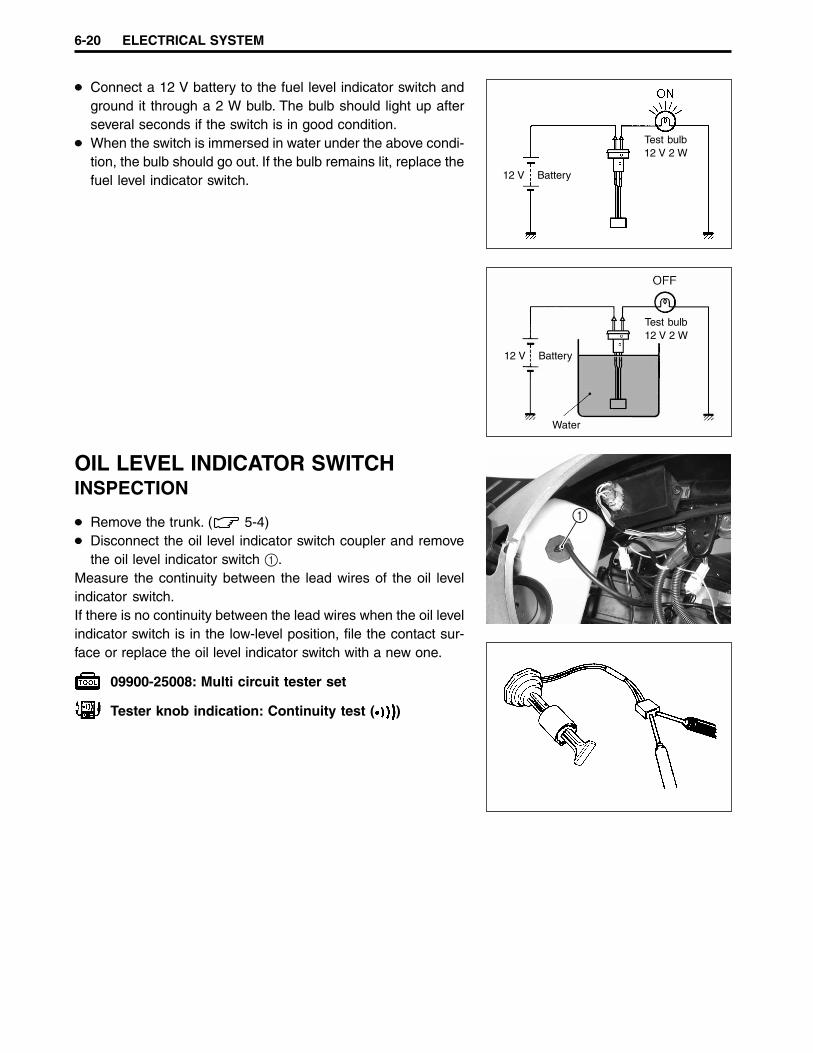
6-20 ELECTRICAL SYSTEM
Connect a 12 V battery to the fuel level indicator switch andground it through a 2 W bulb. The bulb should light up afterseveral seconds if the switch is in good condition.When the switch is immersed in water under the above condi-tion, the bulb should go out. If the bulb remains lit, replace thefuel level indicator switch.
OIL LEVEL INDICATOR SWITCHINSPECTION
Remove the trunk. ( 5-4)Disconnect the oil level indicator switch coupler and removethe oil level indicator switch 1.
Measure the continuity between the lead wires of the oil levelindicator switch.If there is no continuity between the lead wires when the oil levelindicator switch is in the low-level position, file the contact sur-face or replace the oil level indicator switch with a new one.
09900-25008: Multi circuit tester set
Tester knob indication: Continuity test ( )
12 V Battery
Test bulb12 V 2 W
12 V Battery
Test bulb12 V 2 W
Water
1
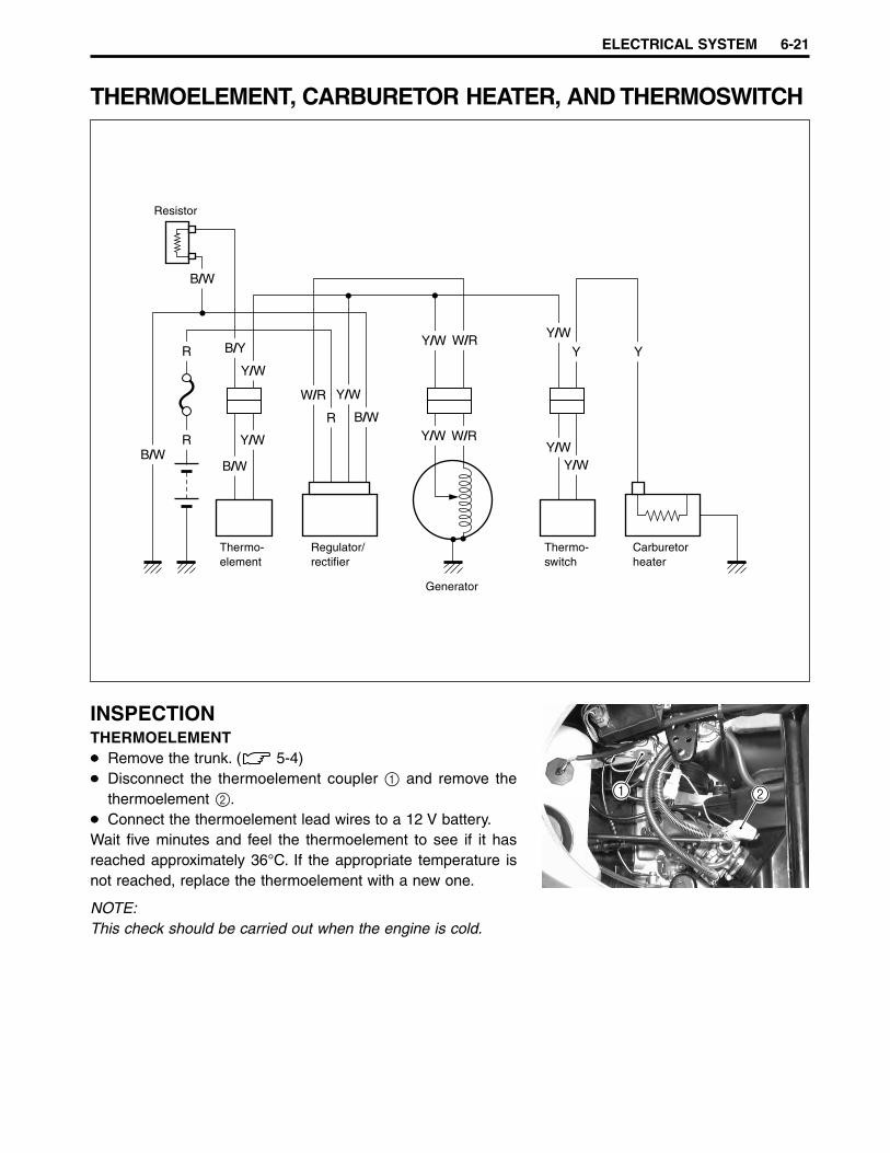
ELECTRICAL SYSTEM 6-21
THERMOELEMENT, CARBURETOR HEATER, AND THERMOSWITCH
INSPECTIONTHERMOELEMENT
Remove the trunk. ( 5-4)Disconnect the thermoelement coupler 1 and remove thethermoelement 2.Connect the thermoelement lead wires to a 12 V battery.
Wait five minutes and feel the thermoelement to see if it hasreached approximately 36°C. If the appropriate temperature isnot reached, replace the thermoelement with a new one.
NOTE:This check should be carried out when the engine is cold.
B/Y
B/W
Y/W
W/R
W/R
W/RY Y
R
R
R
Y/W
Y/WY/W
Y/W
B/WY/W
Y/W
B/W
B/W
Y/W
Thermo-element
Regulator/rectifier
Generator
Thermo-switch
Carburetorheater
1 2
Resistor
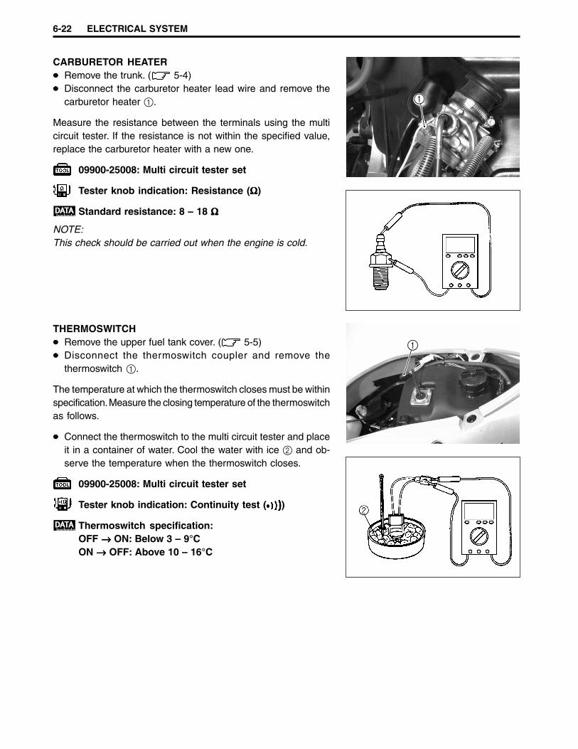
6-22 ELECTRICAL SYSTEM
CARBURETOR HEATERRemove the trunk. ( 5-4)Disconnect the carburetor heater lead wire and remove thecarburetor heater 1.
Measure the resistance between the terminals using the multicircuit tester. If the resistance is not within the specified value,replace the carburetor heater with a new one.
09900-25008: Multi circuit tester set
Tester knob indication: Resistance (ΩΩΩΩΩ)
Standard resistance: 8 – 18 ΩΩΩΩΩ
NOTE:This check should be carried out when the engine is cold.
THERMOSWITCHRemove the upper fuel tank cover. ( 5-5)Disconnect the thermoswitch coupler and remove thethermoswitch 1.
The temperature at which the thermoswitch closes must be withinspecification. Measure the closing temperature of the thermoswitchas follows.
Connect the thermoswitch to the multi circuit tester and placeit in a container of water. Cool the water with ice 2 and ob-serve the temperature when the thermoswitch closes.
09900-25008: Multi circuit tester set
Tester knob indication: Continuity test ( )
Thermoswitch specification:OFF →→→→→ ON: Below 3 – 9°CON →→→→→ OFF: Above 10 – 16°C
1
1
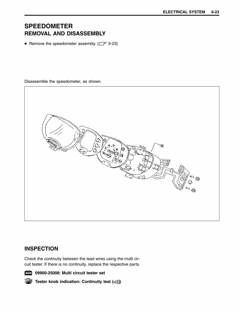
ELECTRICAL SYSTEM 6-23
SPEEDOMETERREMOVAL AND DISASSEMBLY
Remove the speedometer assembly. ( 5-23)
Disassemble the speedometer, as shown.
INSPECTION
Check the continuity between the lead wires using the multi cir-cuit tester. If there is no continuity, replace the respective parts.
09900-25008: Multi circuit tester set
Tester knob indication: Continuity test ( )

6-24 ELECTRICAL SYSTEM
LAMPSHEADLIGHT
HEADLIGHT BULB REPLACEMENTRemove the front leg shield. ( 5-3)Remove the headlight bulb.
If you touch the bulb with your bare hands, clean thebulb with a cloth moistened with alcohol or soapy wa-ter to prevent premature bulb failure.
Headlight bulb: 12 V 35/35 W

ELECTRICAL SYSTEM 6-25
Remove the front turn signal light bulb 3 and rear turn signallight bulb 4.
If you touch the bulb with your bare hands, clean thebulb with a cloth moistened with alcohol or soapy wa-ter to prevent premature bulb failure.
1 2
3 4
FRONT AND REAR TURN SIGNAL LIGHT
FRONT AND REAR TURN SIGNAL LIGHT BULBREPLACEMENT
Remove the front turn signal light lens 1 and rear turn signallight lens 2.
Turn signal light: 12 V 10 W

6-26 ELECTRICAL SYSTEM
BRAKE LIGHT/TAILLIGHT
Remove the brake light/taillight bulb.
If you touch the bulb with your bare hands, clean thebulb with a cloth moistened with alcohol or soapy wa-ter to prevent premature bulb failure.
BRAKE LIGHT/TAILLIGHT BULB REPLACEMENTRemove the brake light/taillight lens.
Brake light/taillight: 12 V 21/5 W
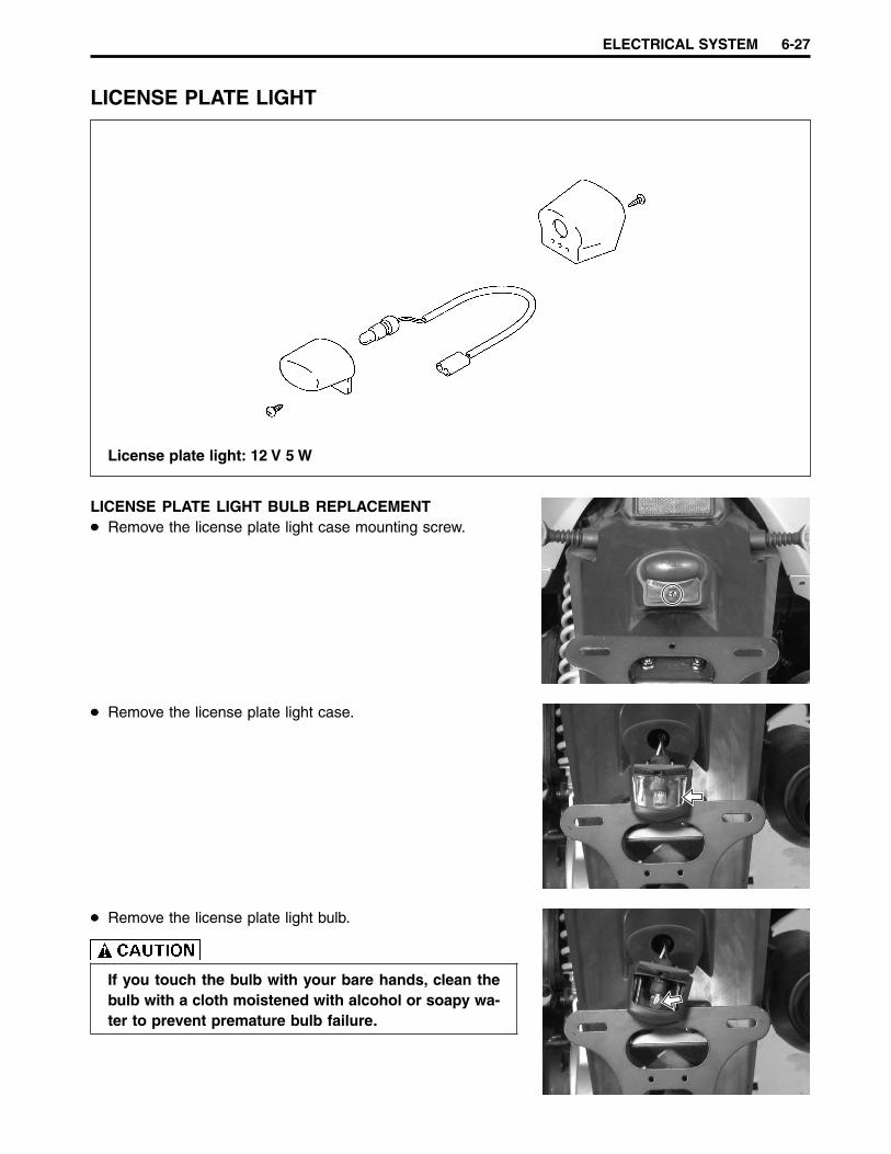
ELECTRICAL SYSTEM 6-27
LICENSE PLATE LIGHT
Remove the license plate light case.
Remove the license plate light bulb.
If you touch the bulb with your bare hands, clean thebulb with a cloth moistened with alcohol or soapy wa-ter to prevent premature bulb failure.
LICENSE PLATE LIGHT BULB REPLACEMENTRemove the license plate light case mounting screw.
License plate light: 12 V 5 W

6-28 ELECTRICAL SYSTEM
RELAYSSTARTER RELAY
The starter relay is located behind the battery holder cover.( 6-30)
TURN SIGNAL RELAY
The turn signal relay is located behind the front leg shield.( 5-3)If the turn signal light does not light, inspect the bulb or repairthe circuit connection.If the bulb and circuit connection are OK, the turn signal relaymay be faulty, replace it with a new one.
NOTE:When making this test, make sure that the battery is fully charged.
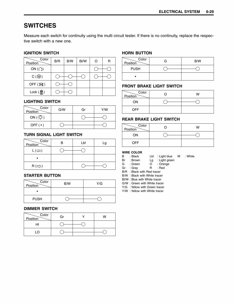
ELECTRICAL SYSTEM 6-29
SWITCHES
Measure each switch for continuity using the multi circuit tester. If there is no continuity, replace the respec-tive switch with a new one.
IGNITION SWITCH
PositionColor B/R B/W Bl/W O R
ON ( )
C ( • )
OFF ( )
Lock ( )
LIGHTING SWITCH
PositionColor G/W Gr Y/W
ON ( )
OFF ( • )
TURN SIGNAL LIGHT SWITCH
PositionColor B Lbl Lg
L ( )
•
R ( )
STARTER BUTTON
PositionColor B/W Y/G
•
PUSH
DIMMER SWITCH
PositionColor Gr Y W
HI
LO
HORN BUTTON
PositionColor G B/W
PUSH
•
FRONT BRAKE LIGHT SWITCH
PositionColor O W
ON
OFF
REAR BRAKE LIGHT SWITCH
PositionColor O W
ON
OFF
WIRE COLORB : Black Lbl : Light blue W : WhiteBr : Brown Lg : Light greenG : Green O : OrangeGr : Gray R : RedB/R : Black with Red tracerB/W : Black with White tracerBl/W : Blue with White tracerG/W : Green with White tracerY/G : Yellow with Green tracerY/W : Yellow with White tracer

6-30 ELECTRICAL SYSTEM
BATTERYREMOVAL
Remove the battery holder cover 1.
Remove the battery.
NOTE:Disconnect the - battery lead wire, first.
REMOUNTING
Remount the battery in the reverse order of removal.
1
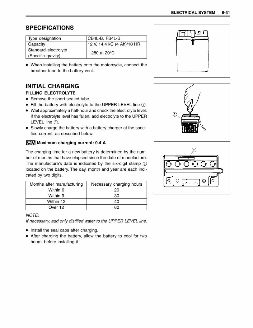
ELECTRICAL SYSTEM 6-31
SPECIFICATIONS
Type designation CB4L-B, FB4L-BCapacity 12 V, 14.4 kC (4 Ah)/10 HRStandard electrolyte
1.280 at 20°C(Specific gravity)
When installing the battery onto the motorcycle, connect thebreather tube to the battery vent.
INITIAL CHARGINGFILLING ELECTROLYTE
Remove the short sealed tube.Fill the battery with electrolyte to the UPPER LEVEL line 1.Wait approximately a half-hour and check the electrolyte level.If the electrolyte level has fallen, add electrolyte to the UPPERLEVEL line 1.Slowly charge the battery with a battery charger at the speci-fied current, as described below.
Maximum charging current: 0.4 A
The charging time for a new battery is determined by the num-ber of months that have elapsed since the date of manufacture.The manufacture’s date is indicated by the six-digit stamp 2
located on the battery. The day, month and year are each indi-cated by two digits.
Months after manufacturing Necessary charging hoursWithin 6 20Within 9 30
Within 12 40Over 12 60
NOTE:If necessary, add only distilled water to the UPPER LEVEL line.
Install the seal caps after charging.After charging the battery, allow the battery to cool for twohours, before installing it.

6-32 ELECTRICAL SYSTEM
SERVICING
Visually inspect the surface of the battery container. If any signsof cracking or electrolyte leakage from the sides of the batteryhave occurred, replace the battery with a new one. If the batteryterminals are found to be coated with rust or an acidic whitepowdery substance, clean the battery terminals with sandpa-per.Check the electrolyte level, and if necessary, add distilled waterto raise the electrolyte level, for each cell, to the UPPER LEVELline.Use a hydrometer to measure the electrolyte specific gravity read-ing. If the reading is 1.22 or less, as corrected to 20°C, this indi-cates that the battery needs to be charged.
Specific gravityCondition Measure
at 20°C1.250 – 1.280 Normal1.220 – 1.250 Under charged ChargeBelow 1.220 Run down Charge or replace
09900-28403: Hydrometer
RECHARGING OPERATIONNOTE:When charging the battery, be sure to remove the battery fromthe motorcycle to protect the regulator/rectifier against exces-sive voltage.
Use the following formula to correct the specific gravity read-ing to 20°C.S20 = St + 0.0007 (t-20)Where S20 = corrected value of specific gravity
(20°C)St = value of specific gravity read at temperature t°C0.0007 = temperature coefficient of specific gravityt = temperature in degrees centigrade at which St was read.Check the corrected specific gravity reading with the chart, todetermine the charging time in hours. This is when a con-stant-current charge at a rate of 0.4 amperes (which is a tenthof the capacity of the present battery) is used.When charging the battery, do not allow the electrolyte tem-perature to exceed 45°C. Interrupt the operation, as neces-sary, to let the electrolyte cool down.
Electrolyte specific gravity: 1.280 at 20°C
Do not quick charge the battery. Quick charging willshorten the life of the battery.
Charging time (hour)
Spe
cific
gra
vity
at
20°C
Temperature
Spe
cific
gra
vity
Recharge
Normal
Recharge or replace

ELECTRICAL SYSTEM 6-33
SERVICE LIFE
Lead oxide is on the plates of the battery and will gradually comeoff of the plates during the life of the battery. When the bottom ofthe battery case becomes full of this sediment, replace the bat-tery. If the battery is not charged for a long period of time, leadsulfate may accumulate on the surface of the plates. If this oc-curs, replace the battery with a new one.
STORAGEWhen a battery is not used for a long period of time, sulfationmay occur. When the motorcycle is not used for more than onemonth (especially during the winter season), the battery shouldbe charged at least once a month.
Before charging the battery, remove the seal cap fromeach cell.Keep fire and sparks away from a battery which isbeing charged.When removing the battery from the motorcycle, besure to remove the - battery terminal, first.
SERVICING INFORMATION 7-1
SERVICING INFORMATION
CONTENTS
TROUBLESHOOTING...................................................................................... 7- 2ENGINE ........................................................................................................ 7- 2CARBURETOR ............................................................................................ 7- 4CHASSIS ...................................................................................................... 7- 5BRAKES ....................................................................................................... 7- 6ELECTRICAL ............................................................................................... 7- 7BATTERY...................................................................................................... 7- 8
WIRING DIAGRAM........................................................................................... 7- 9WIRE HARNESS, CABLE, AND HOSE ROUTING ......................................... 7-10
WIRE HARNESS .......................................................................................... 7-10CABLE ROUTING ........................................................................................ 7-12FUEL SYSTEM HOSE ROUTING................................................................ 7-14BATTERY BREATHER HOSE ROUTING .................................................... 7-15FRONT BRAKE HOSE ROUTING ............................................................... 7-16
SPECIAL TOOLS.............................................................................................. 7-17TIGHTENING TORQUE .................................................................................... 7-19
ENGINE ........................................................................................................ 7-19CHASSIS ...................................................................................................... 7-19TIGHTENING TORQUE CHART .................................................................. 7-20
SERVICE DATA ................................................................................................ 7-21
7

7-2 SERVICING INFORMATION
TROUBLESHOOTINGENGINE
Complaint Symptom and possible causes Remedy
Engine will not startor is hard to start.
Compression too low1. Worn cylinder.2. Worn piston ring.3. Gas leaks from the joint in crankcase, cylinder or cylin-
der head.4. Damaged reed valve.5. Loose spark plug.6. Broken, cracked or damaged piston.
Spark plug not sparking1. Damaged spark plug.2. Damaged spark plug cap.3. Fouled spark plug.4. Wet spark plug.5. Defective ignition coil.6. Defective stator coil.7. Open or short in high-tension cord.8. Defective ignition switch.
No fuel reaching the carburetor1. Clogged hole in the fuel tank cap.2. Clogged or defective fuel valve.3. Defective needle valve.
4. Clogged fuel hose or defective vacuum hose.
Replace.Repair or replace.Repair or replace.
Replace.Tighten.Replace.
Replace.Replace.Clean or replace.Clean and dry or replace.Replace.Replace.Replace.Replace.
Clean or replace.Clean or replace.Replace with needle valveseat.Clean or replace.
Engine stalls easily. 1. Fouled spark plug.2. Defective CDI unit.3. Clogged fuel hose.4. Clogged carburetor jet.5. Clogged exhaust pipe.
Clean or replace.Replace.Clean.Clean.Clean.
Engine is noisy. Noise appears to come from piston1. Worn down piston.2. Worn cylinder.3. Carbon built-up in the combustion chamber.4. Worn piston pin, bearing or piston pin bore.5. Worn piston rings or ring grooves.
Noise seems to come from crankshaft1. Worn or burnt crankshaft bearings.2. Worn or burnt big-end bearing.
Noise seems to come from final gearbox1. Worn or rubbing final gears.2. Worn splines.3. Worn or damaged bearings of driveshaft or rear axle
shaft.
Replace.Replace.Clean.Replace.Replace.
Replace.Replace.
Replace.Replace.Replace.
Clutch slips. 1. Worn or damaged clutch shoes.2. Worn clutch drum.
Replace.Replace.

SERVICING INFORMATION 7-3
Complaint Symptom and possible causes Remedy
Engine idles poorly. 1. Worn cylinder.2. Worn piston rings.3. Stiff piston ring.4. Gas leaks from crankshaft oil seal.5. Excessive spark plug gap.6. Defective ignition coil.7. Defective CDI unit.8. Defective stator coil.9. Incorrect float chamber fuel level.
10. Clogged carburetor jet.11. Broken or damaged reed valve.
Replace.Replace.Replace.Replace.Adjust or replace.Replace.Replace.Replace.Adjust float height.Clean.Replace.
Engine runs poorly inhigh-speed range.
1. Worn cylinder.2. Worn piston rings.3. Stiff piston ring.4. Insufficient spark plug gap.5. Ignition not advanced sufficiently due to poorly work-
ing ignition coil.6. Defective CDI unit.7. Defective stator coil.8. Low float chamber fuel level.9. Dirty air cleaner element.
10. Clogged fuel hose, resulting in inadequate fuel supplyto the carburetor.
11. Clogged fuel valve vacuum pipe.
Replace.Replace.Replace.Regap or replace.Replace.
Replace.Replace.Adjust float height.Clean.Clean and prime.
Clean.
Dirty or heavyexhaust smoke.
1. Incorrect engine oil. Change.
Engine lacks power. 1. Worn cylinder.2. Worn piston rings.3. Stiff piston rings.4. Gas leaks from crankshaft oil seal.5. Insufficient spark plug gap.6. Clogged carburetor jet.7. Incorrect float chamber fuel level.8. Clogged air cleaner element.9. Fouled spark plug.
10. Air leakage from intake pipe.11. Slipping or worn drive belt.12. Damaged or worn rollers in the movable drive face.13. Weakened movable drive face spring.14. Rich air-fuel mixture due to defective starter system.
Replace.Replace.Replace.Replace.Regap or replace.Clean.Adjust float height.Clean.Clean or replace.Tighten or replace.Replace.Replace.Replace.Replace.
Engine overheats. 1. Carbon build-up on piston crown.2. Defective oil pump or clogged oil circuit.3. Low float chamber fuel level.4. Air leakage from intake pipe.5. Incorrect engine oil.6. Incorrect spark plug.7. Clogged exhaust pipe/muffler.
Clean.Clean or replace.Adjust float height.Tighten or replace.Change.Change.Clean or replace.
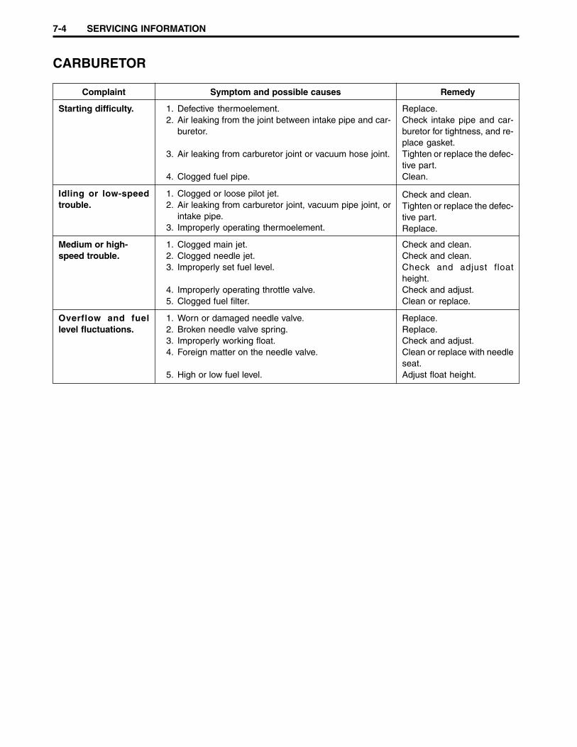
7-4 SERVICING INFORMATION
CARBURETOR
Complaint Symptom and possible causes Remedy
Starting difficulty. 1. Defective thermoelement.2. Air leaking from the joint between intake pipe and car-
buretor.
3. Air leaking from carburetor joint or vacuum hose joint.
4. Clogged fuel pipe.
Replace.Check intake pipe and car-buretor for tightness, and re-place gasket.Tighten or replace the defec-tive part.Clean.
Idling or low-speedtrouble.
1. Clogged or loose pilot jet.2. Air leaking from carburetor joint, vacuum pipe joint, or
intake pipe.3. Improperly operating thermoelement.
Check and clean.Tighten or replace the defec-tive part.Replace.
Medium or high-speed trouble.
1. Clogged main jet.2. Clogged needle jet.3. Improperly set fuel level.
4. Improperly operating throttle valve.5. Clogged fuel filter.
Check and clean.Check and clean.Check and adjust floatheight.Check and adjust.Clean or replace.
Overflow and fuellevel fluctuations.
1. Worn or damaged needle valve.2. Broken needle valve spring.3. Improperly working float.4. Foreign matter on the needle valve.
5. High or low fuel level.
Replace.Replace.Check and adjust.Clean or replace with needleseat.Adjust float height.

SERVICING INFORMATION 7-5
CHASSIS
Complaint Symptom and possible causes Remedy
Steering is heavy. 1. Overtightened steering stem nut.2. Broken bearing/race in steering stem.3. Distorted steering stem.4. Low tire pressure.
Adjust.Replace.Replace.Adjust.
Handlebar wobbles. 1. Loss of balance between right and left front suspen-sion.
2. Distorted front axle or crooked tire.
Replace.
Replace.
Front wheel wobbles. 1. Distorted wheel rim.2. Worn front wheel bearings.3. Defective or incorrect tire.4. Loose front axle nut.5. Loose bolt or nut on the rear shock absorber.6. Worn engine mounting bushing.7. Loose engine mounting nuts or bolts.
Replace.Replace.Replace.Tighten.Tighten.Replace.Tighten.
Front suspension toosoft.
1. Weak springs. Replace.
Front suspension toonoisy.
1. Insufficient grease on the spring and damper.2. Loose front suspension fastener.
Add.Tighten.
Rear wheel wobbles. 1. Distorted wheel rim.2. Defective or incorrect tire.3. Loose rear axle nut.4. Worn engine mounting bushing.5. Loose engine mounting nuts or bolts.
Replace.Replace.Tighten.Replace.Tighten.
Rear suspension toosoft.
1. Weak spring.2. Rear shock absorber leaks oil.
Replace.Replace.
Rear suspension toonoisy.
1. Loose bolt or nut on the rear shock absorber.2. Worn engine mounting bushing.
Tighten.Replace.
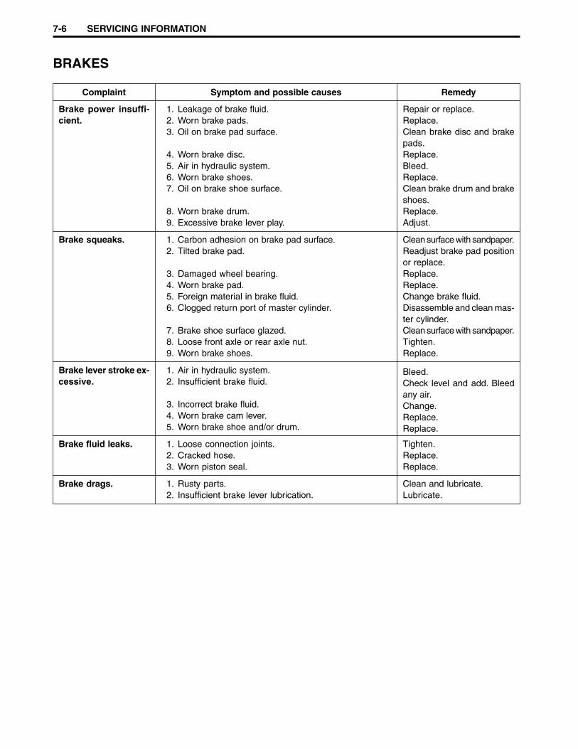
7-6 SERVICING INFORMATION
BRAKES
Complaint Symptom and possible causes Remedy
Brake power insuffi-cient.
1. Leakage of brake fluid.2. Worn brake pads.3. Oil on brake pad surface.
4. Worn brake disc.5. Air in hydraulic system.6. Worn brake shoes.7. Oil on brake shoe surface.
8. Worn brake drum.9. Excessive brake lever play.
Repair or replace.Replace.Clean brake disc and brakepads.Replace.Bleed.Replace.Clean brake drum and brakeshoes.Replace.Adjust.
Brake squeaks. 1. Carbon adhesion on brake pad surface.2. Tilted brake pad.
3. Damaged wheel bearing.4. Worn brake pad.5. Foreign material in brake fluid.6. Clogged return port of master cylinder.
7. Brake shoe surface glazed.8. Loose front axle or rear axle nut.9. Worn brake shoes.
Clean surface with sandpaper.Readjust brake pad positionor replace.Replace.Replace.Change brake fluid.Disassemble and clean mas-ter cylinder.Clean surface with sandpaper.Tighten.Replace.
Brake lever stroke ex-cessive.
1. Air in hydraulic system.2. Insufficient brake fluid.
3. Incorrect brake fluid.4. Worn brake cam lever.5. Worn brake shoe and/or drum.
Bleed.Check level and add. Bleedany air.Change.Replace.Replace.
Brake fluid leaks. 1. Loose connection joints.2. Cracked hose.3. Worn piston seal.
Tighten.Replace.Replace.
Brake drags. 1. Rusty parts.2. Insufficient brake lever lubrication.
Clean and lubricate.Lubricate.

SERVICING INFORMATION 7-7
ELECTRICAL
Complaint Symptom and possible causes Remedy
No sparking or poorsparking.
1. Defective ignition coil.2. Defective spark plug.3. Defective stator coil or pickup coil.4. Defective CDI unit.5. Loose connection of lead wire.
Replace.Replace.Replace.Replace.Connect or tighten.
Spark plug soon be-comes fouled withcarbon.
1. Excessively rich air-fuel mixture.2. High idling speed.3. Incorrect gasoline.4. Dirty air cleaner element.5. Incorrect spark plug (cold type).
6. Incorrect engine oil.
Adjust carburetor.Adjust carburetor.Change.Clean or replace.Change to hot type sparkplug.Replace.
Spark plug electrodesoverheat or burn.
1. Incorrect spark plug (hot type).2. Overheated engine.3. Loose spark plug.4. Excessively lean air-fuel mixture.5. Not enough engine oil.
Change to cold type plug.Tune-up.Tighten.Adjust carburetor.Check oil pump.
Generator does notcharge.
1. Open or short in lead wires, or loose lead connections.2. Shorted, grounded, or open generator coil.3. Shorted or punctured regulator/rectifier.
Repair, replace or tighten.Replace.Replace.
Generator chargesbut charging rate isbelow the specifica-tions.
1. Lead wires tend to get shorted or open-circuited orloosely connected at terminal.
2. Grounded or open-circuited stator coils or generator.3. Defective regulator/rectifier.4. Defective battery cell.
Repair or tighten.
Replace.Replace.Replace battery.
Generator over-charges.
1. Internal short-circuit in the battery.2. Defective regulator/rectifier.
Replace battery.Replace.
Unstable charging. 1. Lead wire insulation frayed due to vibration, resultingin intermittent shorting.
2. Internally shorted generator.3. Defective regulator/rectifier.
Repair or replace.
Replace.Replace.
Starter switch doesnot work.
1. Run down battery.2. Defective switch contacts.3. Brushes do not seat properly on the commutator in the
starter motor.4. Defective starter relay.5. Defective starter pinion gear assembly.6. Defective front or rear brake light switch circuit.
Recharge or replace.Replace.Repair or replace.
Replace.Replace.Repair or replace.

7-8 SERVICING INFORMATION
BATTERY
Complaint Symptom and possible causes Remedy
Sulfation, acidic whitepowdery substanceor spots on surfacesof cell plates.
1. Insufficient electrolyte.
2. Cracked battery case.3. Battery has been left in a run-down condition for a long
time.4. Foreign matter has entered the battery and has be-
come mixed with the electrolyte.
Add distilled water, if the bat-tery has not been damagedand sulfation has not ad-vanced too far, then re-charge.Replace.Replace.
If sulfation has not advancedtoo far, try to restore the bat-tery by replacing the electro-lyte, recharging it fully withthe battery detached fromthe motorcycle and then ad-justing the electrolyte spe-cific gravity.
Battery runs downquickly.
1. Incorrect charging method.
2. Battery cell plates have lost much of their active mate-rial as a result of overcharging.
3. A short-circuit condition exists within the battery to ex-cessive accumulation of sediments caused by the highelectrolyte specific gravity.
4. Low electrolyte specific gravity.
5. Foreign matter has entered the battery and has be-come mixed with the electrolyte.
6. Old battery.
Check the generator, regula-tor/rectifier and circuit con-nections and make neces-sary adjustments to obtainspecified charging operation.Replace and correct thecharging system.Replace.
Recharge and adjust electro-lyte specific gravity.Replace the electrolyte, re-charge the battery, and thenadjust specific gravity.Replace.
Reversed battery po-larity.
1. Improperly connected battery leads.(i.e., - to + and + to -)
Replace the battery and besure to connect it properly.
Battery “sulfation” 1. Incorrect charging rate. (When not in use, the batteryshould be checked at least once a month to avoidsulfation.)
2. Excessive or insufficient battery electrolyte or high orlow specific gravity.
3. The battery was left unused for too long in a cold cli-mate.
Replace.
Keep the electrolyte at theprescribed level, or adjust thespecific gravity by consultingthe battery manufacturer’s di-rections.Replace the battery if badlysulfated.
Battery dischargestoo rapidly.
1. Dirty container top and sides.2. Impurities in the electrolyte or electrolyte specific grav-
ity is too high.
Clean.Change the electrolyte byconsulting the batterymanufacturer’s directions.
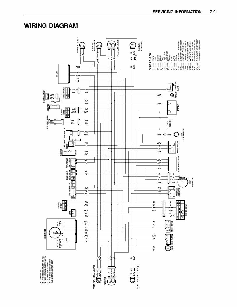
SERVICING INFORMATION 7-9
WIRING DIAGRAM
FUHI
TLTR
OI
SP
OFFON
•PU
SH
ON
OFF
ON
OFF
SPEE
DOME
TER
DIOD
ELI
GHTI
NG S
WIT
CH
STAR
TER
BUTT
ON
REAR
BRA
KELI
GHT
SWIT
CHFR
ONT
BRAK
ELI
GHT
SWIT
CH
RESI
STOR
TURN
SIG
NAL
RELA
YIG
NITI
ON C
OILFU
EL L
EVEL
SW
ITCH OI
L LE
VEL
SWIT
CHO
NO
FF
THER
MOSW
ITCH
CDI U
NIT
ON
OFF
THER
MOEL
EMEN
T
REAR
TUR
NSI
GNAL
LIG
HT(R
)
LICE
NSE
PLAT
E LI
GHT
REAR
TUR
NSI
GNAL
LIG
HT(L
)
BRAK
E LI
GHT/
TAIL
LIGH
T
GROU
NDBA
TTER
Y
FUSE
BOX
CARB
URET
ORHE
ATER
STAR
TER
MOTO
R
STAR
TER
RELA
YRE
GULA
TOR/
RECT
IFIE
R
GENE
RATO
R
TURN
SIG
NAL
LIGH
T SW
ITCH
•L R
CON
LOCK
OFF
IGNI
TION
SW
ITCH
HORN
BUT
TON
DIMM
ER S
WIT
CHHO
RN
•PU
SHLOHI
FRON
T TU
RN S
IGNA
L LI
GHT
(L)
FRON
T TU
RN S
IGNA
L LI
GHT
(R)
HEAD
LIGH
T
RESI
STOR
SP :
SPEE
DOME
TER
TR :
TURN
SIG
NAL
INDI
CATO
R LI
GHT
(R)
TL :
TURN
SIG
NAL
INDI
CATO
R LI
GHT
(L)
OI :
OIL
LEV
EL IN
DICA
TOR
LIGH
TFU
: FU
EL L
EVEL
INDI
CATO
R LI
GHT
HI :
HIGH
BEA
M IN
DICA
TOR
LIGH
T
Bla
ckB
lue
Bro
wn
Gre
enG
ray
Ligh
t blu
eLi
ght g
reen
Ora
nge
Red
Whi
teY
ello
wB
lack
with
Whi
te tr
acer
Bla
ck w
ith Y
ello
w tr
acer
Blu
e w
ith W
hite
trac
erG
reen
with
Whi
te tr
acer
Red
with
Whi
te tr
acer
Whi
te w
ith B
lue
trac
erW
hite
with
Red
trac
erY
ello
w w
ith B
lack
trac
erY
ello
w w
ith G
reen
trac
erY
ello
w w
ith W
hite
trac
er
WIR
E C
OL
OR
S
Lg
B/W
Lg
B/W
YY
WW
W
W
W
W
W
Gr
B/W
B/W
BB
/WB
B
B
B/W
O
O
O
WO
G
Bl/WBl
Br
ROR
R
R
R
R
R
B/W
B/W
B/W
B/W
G
Y/G
R/W
R/W R/W
W/R
W/R
B/W
B/W
Y/W
WBr
W/RY/W
Y/W
Y
Lg
LgO
Lbl
B/RR/B
Y
Y
Lg
Lg
BB
/WB
B/W
B/W
B/W Gr
Gr
Bl/W
Bl/W
G/W
G/W
B/W
W/Bl
W/Bl
B/W
B/W
B/W
B/WB/W
B/W
Bl
Gr
Gr
Y/W
Y/W
Y/BB/W
B/W
Y/B
Y/W
Y/W
Y/W Y/W
O
Lbl
Bl/W Bl/W
Y/G
Y/B
Y/B
B/W
B/W
O
WBr
Y
B Bl
Br
G Gr
Lbl
Lg O R W Y B/W
B/Y
Bl/W
G/W
R/W
W/B
lW
/RY
/BY
/GY
/W. . .
. . .
. . .
. . .
. . .
. . .
. . .
. . .
. . .
. . .
. .
. . .
. . .
. . .
. . .
. . .
. . .
. . .
. . .
. . .
. . .
. . .
.
. . .
. .
. . .
.
. . .
.
. . .
.
. . .
.
. . .
.
. . .
. .
. . .
. .
. . .
.
. . .
B/Y
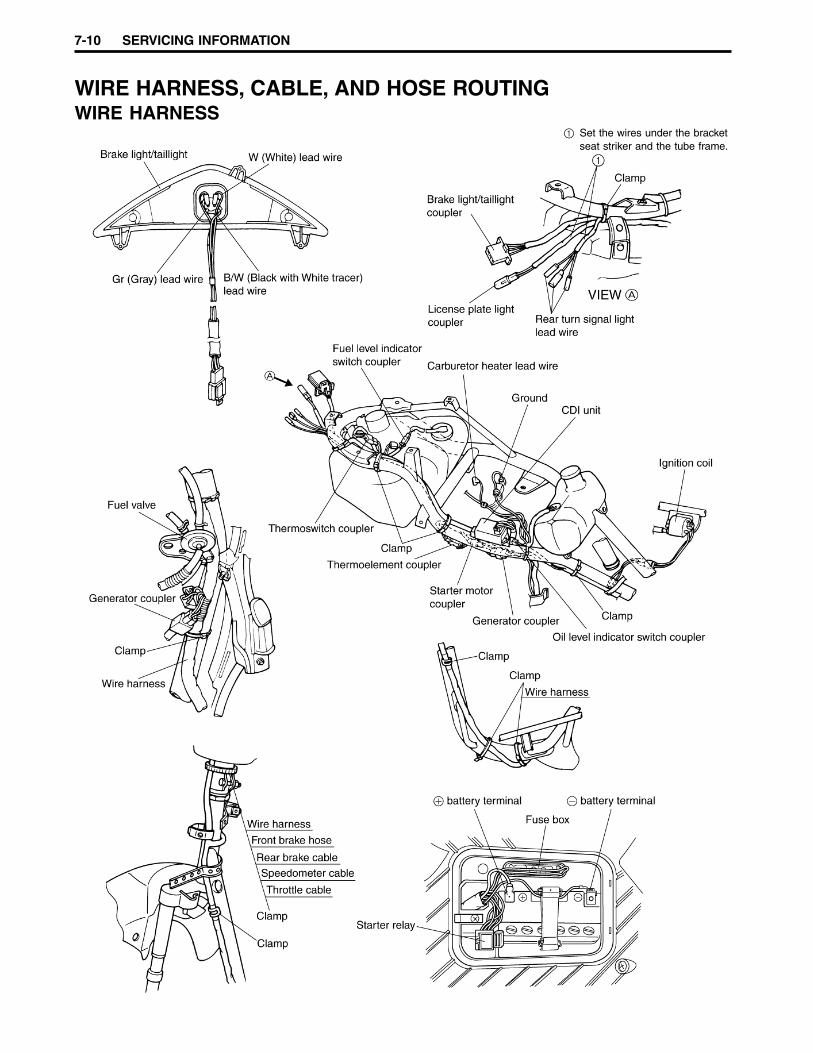
7-10 SERVICING INFORMATION
WIRE HARNESS, CABLE, AND HOSE ROUTINGWIRE HARNESS
1 Set the wires under the bracketseat striker and the tube frame.

SERVICING INFORMATION 7-11
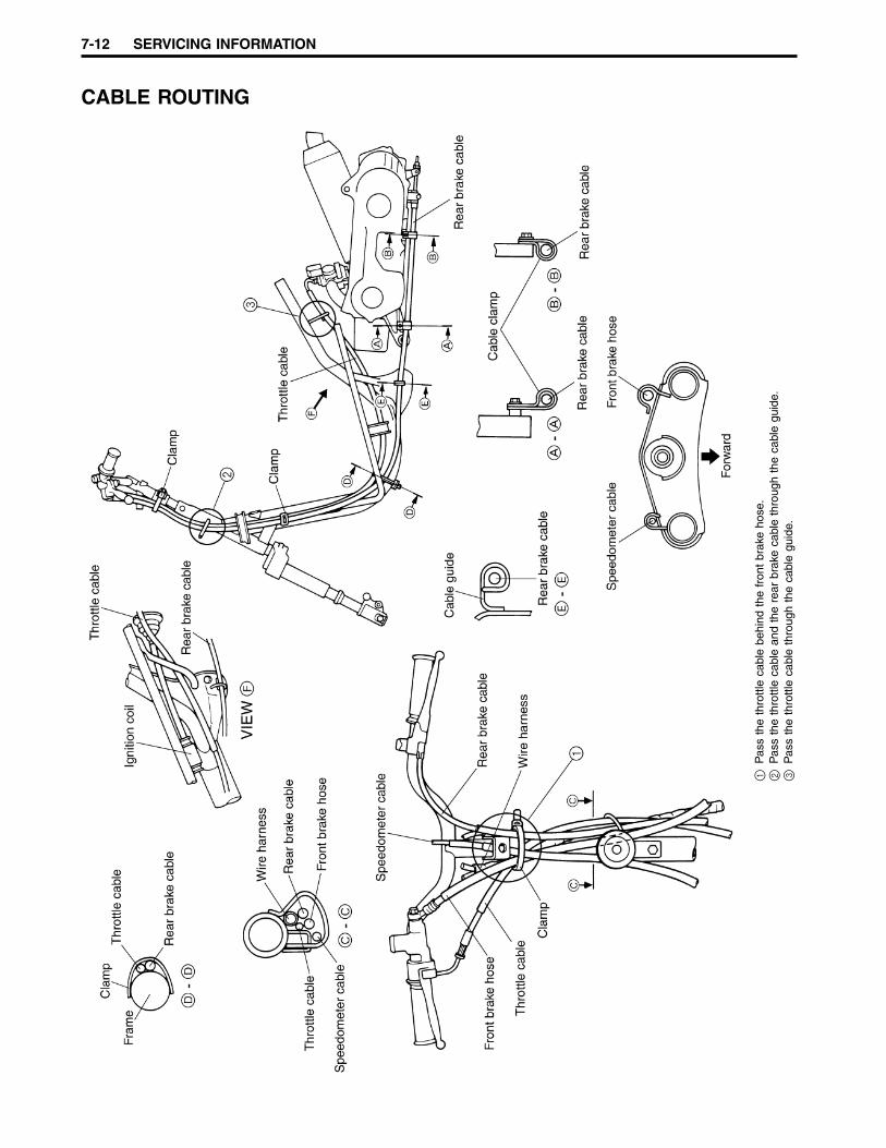
7-12 SERVICING INFORMATION
CABLE ROUTING
1P
ass
the
thro
ttle
cabl
e be
hind
the
fro
nt b
rake
hos
e.2
Pas
s th
e th
rottl
e ca
ble
and
the
rear
bra
ke c
able
thr
ough
the
cab
le g
uide
.3
Pas
s th
e th
rottl
e ca
ble
thro
ugh
the
cabl
e gu
ide.
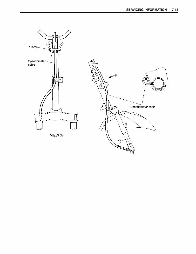
SERVICING INFORMATION 7-13

7-14 SERVICING INFORMATION
B
A
Fue
l val
veF
uel h
ose
Vac
uum
hos
e
To th
e ca
rbur
etor
To th
e ca
rbur
etor
Cla
mp
Cla
mp
Air
vent
hos
e
Fue
l hos
e
Fue
l val
ve
Vac
uum
hos
e
Eng
ine
oil h
ose
Cla
mp
Oil
drai
n ho
se
Oil
drai
n ho
se
VIE
W A
VIE
W B
Fue
l hos
e
FUEL SYSTEM HOSE ROUTING

SERVICING INFORMATION 7-15
BATTERY BREATHER HOSE ROUTING
Breather hose
Battery
Forward
Forward Cushion
65 m
m 15 m
m
Slit position
NOTE:The slit on the breather hose must facebattery side.

7-16 SERVICING INFORMATION
FRONT BRAKE HOSE ROUTING
1P
ass
the
brak
e ho
se in
fro
nt o
f th
e w
ire h
arne
ss a
nd e
ach
cabl
e.2
Pas
s th
e br
ake
hose
thr
ough
the
hos
e gu
ide.
3C
lam
p th
e sl
eeve
firm
ly.
4T
ight
en t
he b
rake
hos
e un
ion
bolt
so t
hat
the
hose
is p
aral
lel t
o th
e ha
ndle
bar.
5T
ight
en t
he b
rake
hos
e un
ion
bolt
so t
hat
the
hose
is c
onta
ctin
g th
e st
oppe
r.
VIE
W A
VIE
W B
VIE
W C
VIE
W D
A
B
C
D
Mas
ter
cylin
der
Wire
har
ness
Rea
r br
ake
cabl
e
Fron
t bra
ke h
ose
Cla
mp
Hos
e gu
ide
Spe
edom
eter
cab
le
Thr
ottle
cab
le
Fron
t bra
ke h
ose
Cla
mp
Fron
t bra
ke c
alip
erFr
ont b
rake
dis
c
35˚
14˚
5
3
4
35˚
1 2
Fron
t bra
ke h
ose
Hos
e gu
ide
Hos
e gu
ide

SERVICING INFORMATION 7-17
09920-13120Crankcase separat-ing tool
09921-20210Bearing remover
SPECIAL TOOLS
09900-00401Hexagon wrenchset
09900-06107Snap ring pliers
09900-06108Snap ring pliers
09900-09003Impact driver set
09900-20101Vernier calipers(150 mm)
09900-20202Micrometer(25 – 50 mm)
09900-20205Micrometer(0 – 25 mm)
09900-20508Cylinder boregauge set
09900-20605Dial calipers
09900-20606Dial gauge(1/100 mm)
09900-20701Magnetic stand
09900-20803Thickness gauge
09900-20804Thickness gauge
09900-20805Tire depth gauge
09900-21304V-block (100 mm)
09900-21602CCI oil gauge
09900-25008Multi circuit testerset
09900-28403Hydrometer
09910-20116Conrod holder
09910-32812Crankshaft installer
09910-60611Universal clampwrench
09913-50121Oil seal remover
09913-70210Bearing installerset

7-18 SERVICING INFORMATION
09923-73210Bearing remover
09923-74510Bearing remover
09924-84521Bearing installerset
09930-30102Sliding hammer
09930-40113Rotor holder
09940-52860Front fork oil sealinstaller
09941-34513Steering inner raceinstaller
09941-50111Bearing remover
09941-74910Bearing installer
09943-88211Bearing remover/installer
09921-20220Bearing removerset
09930-40131Rotor holderattachment
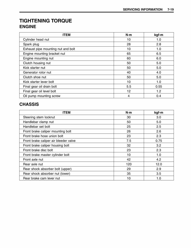
SERVICING INFORMATION 7-19
TIGHTENING TORQUEENGINE
ITEM N·m kgf-mCylinder head nut 10 1.0Spark plug 28 2.8Exhaust pipe mounting nut and bolt 10 1.0Engine mounting bracket nut 65 6.5Engine mounting nut 60 6.0Clutch housing nut 50 5.0Kick starter nut 50 5.0Generator rotor nut 40 4.0Clutch shoe nut 50 5.0Kick starter lever bolt 10 1.0Final gear oil drain bolt 5.5 0.55Final gear oil level bolt 12 1.2Oil pump mounting screw 4 0.4
CHASSIS
ITEM N·m kgf-mSteering stem locknut 30 3.0Handlebar clamp nut 50 5.0Handlebar set bolt 25 2.5Front brake caliper mounting bolt 26 2.6Front brake hose union bolt 23 2.3Front brake caliper air bleeder valve 7.5 0.75Front brake caliper housing bolt 32 3.2Front brake disc bolt 23 2.3Front brake master cylinder bolt 10 1.0Front axle nut 42 4.2Rear axle nut 120 12.0Rear shock absorber bolt (upper) 29 2.9Rear shock absorber nut (lower) 35 3.5Rear brake cam lever nut 10 1.0
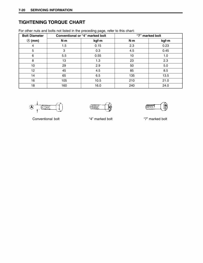
7-20 SERVICING INFORMATION
TIGHTENING TORQUE CHART
For other nuts and bolts not listed in the preceding page, refer to this chart:Bolt Diameter Conventional or “4” marked bolt “7” marked bolt
A (mm) N·m kgf-m N·m kgf-m
4 1.5 0.15 2.3 0.23
5 3 0.3 4.5 0.45
6 5.5 0.55 10 1.0
8 13 1.3 23 2.3
10 29 2.9 50 5.0
12 45 4.5 85 8.5
14 65 6.5 135 13.5
16 105 10.5 210 21.0
18 160 16.0 240 24.0
Conventional bolt “4” marked bolt “7” marked bolt

SERVICING INFORMATION 7-21
SERVICE DATACYLINDER + PISTON + PISTON RING
Unit: mmITEM STANDARD LIMIT
Piston to cylinder clearance 0.06 – 0.07 0.120
Cylinder bore 41.005 – 41.020Measure at 20 mm from the top surface 41.075
Piston diameter 40.940 – 40.955Measure at 15 mm from the skirt end 40.885
Cylinder distortion — 0.05
Cylinder head distortion — 0.05
Piston ring free end gap 1st R Approximately 4.0 3.2
R Approximately 4.3 3.4
Piston ring end gap 1st & 2nd R 0.10 – 0.25 0.80
Piston-ring-to-piston-ring-groove clear-ance
1st 0.03 – 0.07 —
Piston pin bore 10.002 – 10.010 10.030
Piston pin O.D. 9.995 – 10.000 9.980
CONROD + CRANKSHAFTUnit: mm
ITEM STANDARD LIMITConrod small end I.D. 14.003 – 14.011 14.040
Conrod deflection — 3.0
Crank web to web width 36.0 ± 0.05 —
Crankshaft runout — 0.05
OIL PUMP
ITEM SPECIFICATIONOil pump reduction ratio 30.000 (30/1)
Oil pump discharge rate 0.8 – 1.2 mlfor 5 minutes at 3 000 r/min
CLUTCHUnit: mm
ITEM STANDARD LIMITClutch wheel I.D. 110.00 – 110.15 110.50
Clutch shoe thickness 3.0 2.0
Clutch engagement 4 100 – 4 500 r/min —
Clutch lock-up
2nd 0.02 – 0.06 —
5 600 – 6 200 r/min —
2nd

7-22 SERVICING INFORMATION
TRANSMISSIONUnit: mm Except ratio
ITEM STANDARD LIMITReduction ratio Variable 2.975 – 1.033 —
Final reduction ratio 13.812 (51/15 × 65/16) —
Drive belt width 18.4 17.4
Driven face spring free length 110 104.5
CARBURETOR
ITEM SPECIFICATIONCarburetor type KEIHIN PWS14
Bore size 14 mm
I.D. No. 30F0
Idle r/min 1 900 ± 200 r/min
Float height 5.1 ± 0.5 mm
Main jet (M.J.) # 65
Jet needle (J.N.) N5GJ-2nd
Slow jet (S.J.) # 42
Air screw (A.S.) 2 turns back
Throttle cable play 2 – 4 mm
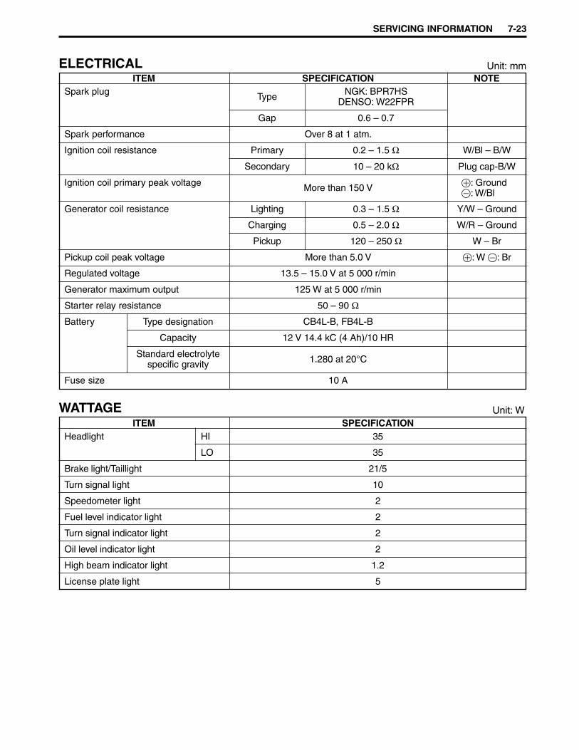
SERVICING INFORMATION 7-23
ELECTRICAL Unit: mmITEM SPECIFICATION NOTE
Spark plug Type NGK: BPR7HSDENSO: W22FPR
Gap 0.6 – 0.7
Spark performance Over 8 at 1 atm.
Ignition coil resistance Primary 0.2 – 1.5 Ω W/Bl – B/W
Generator coil resistance Lighting 0.3 – 1.5 Ω Y/W – Ground
Pickup 120 – 250 Ω W – Br
Regulated voltage 13.5 – 15.0 V at 5 000 r/min
Generator maximum output 125 W at 5 000 r/min
Starter relay resistance 50 – 90 Ω
Battery Type designation CB4L-B, FB4L-B
Capacity 12 V 14.4 kC (4 Ah)/10 HR
Standard electrolytespecific gravity 1.280 at 20°C
Fuse size 10 A
WATTAGE Unit: WITEM SPECIFICATION
Headlight HI 35
LO 35
Brake light/Taillight 21/5
Turn signal light 10
Speedometer light 2
Fuel level indicator light 2
Turn signal indicator light 2
Oil level indicator light 2
High beam indicator light 1.2
License plate light 5
Secondary 10 – 20 kΩ Plug cap-B/W
Ignition coil primary peak voltage More than 150 V +: Ground-: W/Bl
Charging 0.5 – 2.0 Ω W/R – Ground
Pickup coil peak voltage More than 5.0 V +: W -: Br
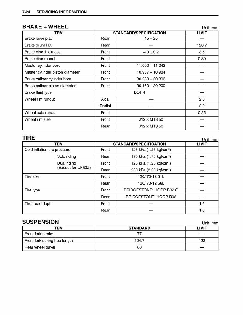
7-24 SERVICING INFORMATION
BRAKE + WHEEL Unit: mmITEM STANDARD/SPECIFICATION LIMIT
Brake lever play Rear 15 – 25 —
Brake drum I.D. Rear — 120.7
Brake disc thickness Front 4.0 ± 0.2 3.5
Brake disc runout Front — 0.30
Master cylinder bore Front 11.000 – 11.043 —
Master cylinder piston diameter Front 10.957 – 10.984 —
Brake caliper cylinder bore Front 30.230 – 30.306 —
Brake caliper piston diameter Front 30.150 – 30.200 —
Brake fluid type DOT 4 —
Wheel rim runout Axial — 2.0
Radial — 2.0
Wheel axle runout Front — 0.25
Wheel rim size Front J12 × MT3.50 —
Rear J12 × MT3.50 —
TIREITEM STANDARD/SPECIFICATION LIMIT
Cold inflation tire pressure
Solo riding
Front 125 kPa (1.25 kgf/cm2)
175 kPa (1.75 kgf/cm2)
Dual riding(Except for UF50Z)
Front 125 kPa (1.25 kgf/cm2)
Rear 230 kPa (2.30 kgf/cm2)
Tire type Front BRIDGESTONE: HOOP B02 G
Rear BRIDGESTONE: HOOP B02
Tire tread depth Front — 1.6
Rear — 1.6
Tire size Front 120/ 70-12 51L
Rear 130/ 70-12 56L
—
—
—
Rear —
—
—
—
—
SUSPENSION Unit: mmITEM STANDARD LIMIT
Front fork stroke 77 —
Front fork spring free length 124.7 122
Rear wheel travel 60 —
Unit: mm

SERVICING INFORMATION 7-25
FUEL + OILITEM SPECIFICATION NOTE
Fuel type Use only gasoline that is graded 91 octane or higher.Unleaded gasoline is recommended.
Fuel tank capacity 6.0 L
Engine oil type Use SUZUKI CCI SUPER OIL. If not available, usea good quality 2-stroke oil rated FC under JASOclassification.
Engine oil tank capacity 1.2 L
Final gear oil type SAE 10W-40
Final gear oil capacity 130 ml

UF50K1 AND UF50ZK1 (’01-MODEL) 8-1
UF50K1 AND UF50ZK1 (’01-MODEL)
8
CONTENTS
SPECIFICATIONS ............................................................................................ 8- 2SERVICE DATA ................................................................................................ 8- 4WIRE HARNESS ROUTING ............................................................................ 8- 7

8-2 UF50K1 AND UF50ZK1 (’01-MODEL)
SPECIFICATIONSDIMENSIONS AND DRY MASS
Overall length ................................................... 1 840 mmOverall width .................................................... 650 mmOverall height ................................................... 1 095 mmWheelbase ....................................................... 1 255 mmGround clearance ............................................ 135 mmSeat height ....................................................... 795 mmDry mass .......................................................... 83 kg
ENGINE
Type .................................................................Two-stroke, forced air-cooledIntake system ...................................................Reed valveNumber of cylinders ......................................... 1Bore .................................................................41.0 mmStroke ............................................................... 37.4 mmPiston displacement ........................................ 49 cm3
Corrected compression ratio ........................... 7.2:1Carburetor ........................................................KEIHIN PWS14Air cleaner ........................................................Polyurethane foam elementStarter system..................................................Electric and kickLubrication system ...........................................SUZUKI “CCI”
TRANSMISSION
Clutch ...............................................................Dry shoe, automatic, centrifugal typeGearshifting .....................................................Automatic, variable ratioGear ratios .......................................................Variable reduction ratio... (2.975 – 1.033)Final reduction ratio ......................................... 13.812 (51/15) × (65/16)Drive system ....................................................V-belt drive

UF50K1 AND UF50ZK1 (’01-MODEL) 8-3
CHASSIS
Front suspension ............................................. Inverted telescopic, coil springRear suspension ..............................................Swingarm type, coil spring, oil dampedSteering angle.................................................. 45° (right & left)Caster .............................................................. 25°30’Trail .................................................................. 82 mmTurning radius .................................................. 1.9 mFront brake .......................................................Disc brakeRear brake ....................................................... Internal expandingFront tire size ................................................... 120/70-12 51LRear tire size .................................................... 130/70-12 56L
ELECTRICAL
Ignition type .....................................................Electronic ignition (CDI)Spark plug ........................................................NGK: BPR7HS or DENSO: W22FPRBattery ............................................................. 12 V 14.4 kC (4 Ah)/10 HRGenerator .........................................................GeneratorFuse ................................................................. 10 AHeadlight .......................................................... 12 V 35/35 WBrake light/taillight ............................................ 12 V 21/5 WTurn signal light ................................................ 12 V 10 W
CAPACITIES
Fuel tank .......................................................... 6.0 LEngine oil tank ................................................. 1.2 LFinal gear oil .................................................... 130 ml
NOTE:These specifications are subject to change without notice.
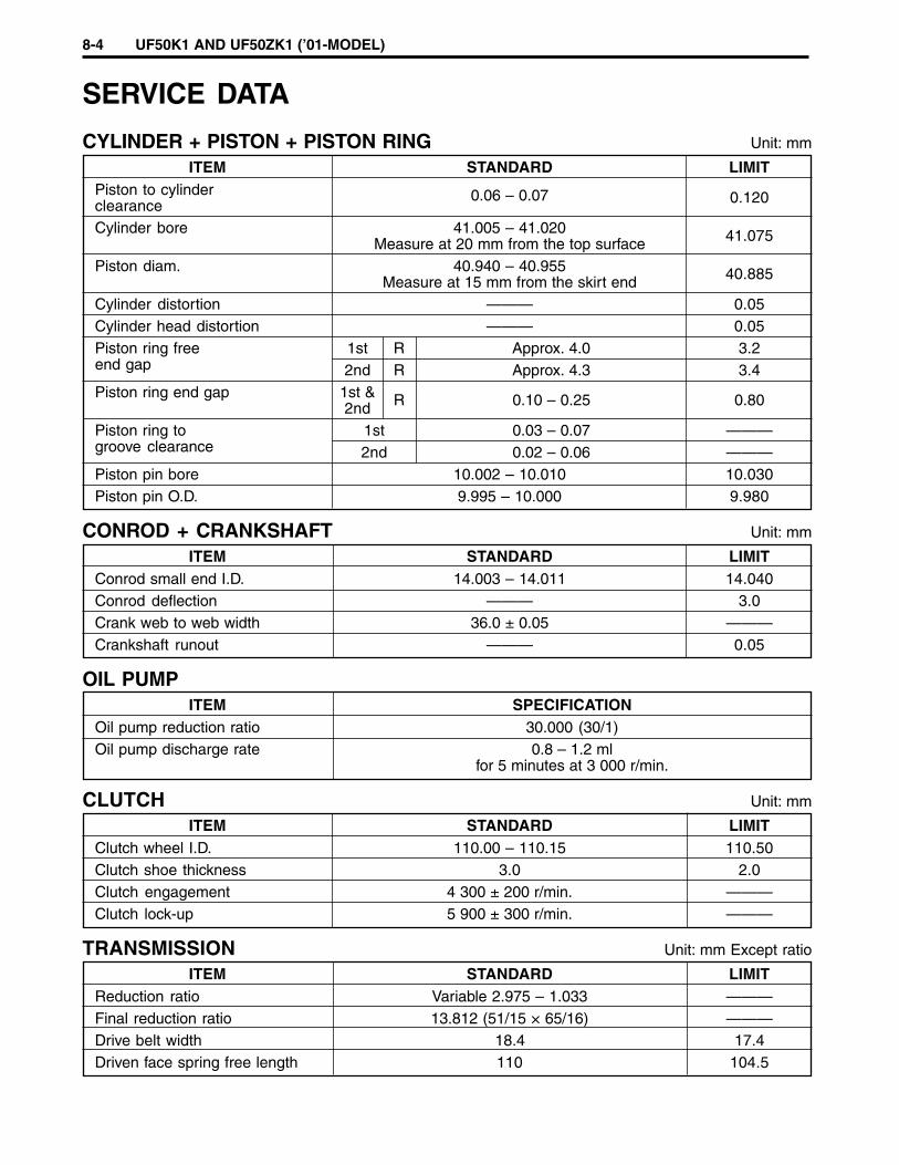
8-4 UF50K1 AND UF50ZK1 (’01-MODEL)
CYLINDER + PISTON + PISTON RING Unit: mm
ITEM STANDARD LIMITPiston to cylinderclearance
0.06 – 0.07 0.120
Cylinder bore 41.005 – 41.020Measure at 20 mm from the top surface 41.075
Piston diam. 40.940 – 40.955Measure at 15 mm from the skirt end 40.885
Cylinder distortion ——— 0.05Cylinder head distortion ——— 0.05Piston ring free 1st R Approx. 4.0 3.2end gap 2nd R Approx. 4.3 3.4Piston ring end gap 1st &
2nd R 0.10 – 0.25 0.80
Piston ring to 1st 0.03 – 0.07 ———groove clearance 2nd 0.02 – 0.06 ———Piston pin bore 10.002 – 10.010 10.030Piston pin O.D. 9.995 – 10.000 9.980
CONROD + CRANKSHAFT Unit: mm
ITEM STANDARD LIMITConrod small end I.D. 14.003 – 14.011 14.040Conrod deflection ——— 3.0Crank web to web width 36.0 ± 0.05 ———Crankshaft runout ——— 0.05
OIL PUMPITEM SPECIFICATION
Oil pump reduction ratio 30.000 (30/1)Oil pump discharge rate 0.8 – 1.2 ml
for 5 minutes at 3 000 r/min.
CLUTCH Unit: mm
ITEM STANDARD LIMITClutch wheel I.D. 110.00 – 110.15 110.50Clutch shoe thickness 3.0 2.0Clutch engagement 4 300 ± 200 r/min. ———Clutch lock-up 5 900 ± 300 r/min. ———
TRANSMISSION Unit: mm Except ratio
ITEM STANDARD LIMITReduction ratio Variable 2.975 – 1.033 ———Final reduction ratio 13.812 (51/15 × 65/16) ———Drive belt width 18.4 17.4Driven face spring free length 110 104.5
SERVICE DATA

UF50K1 AND UF50ZK1 (’01-MODEL) 8-5
CARBURETORITEM SPECIFICATION
Carburetor type KEIHIN PWS14Bore size 14 mmI.D. No. 30F0Idle r/min. 1 900 ± 200 r/min.Float height 5.1 ± 0.5 mmMain jet (M.J.) #65Jet needle (J.N.) N5GJ-2ndSlow jet (S.J.) #42Air screw (A.S.) 2 turns backThrottle cable play 2 – 4 mm
ELECTRICAL Unit: mm
ITEM SPECIFICATION NOTESpark plug NGK: BPR7HSType DENSO: W22FPR
Gap 0.6 – 0.7Spark performance Over 8 at 1 atm.Ignition coil resistance Primary 0.2 – 1.5 Ω W/Bl – B/W
Secondary 10 – 20 kΩ Plug cap – B/W
Ignition coil primary peak voltage More than 150 V : Ground : W/Bl
Generator coil resistance Lighting 0.3 – 1.5 Ω Y/W – Ground
Charging 0.5 – 2.0 Ω W/R – GroundPick-up 120 – 250 Ω W – Br
Pick-up coil peak voltage More than 5.0 V : W : Br
Regulated voltage 13.5 – 15.0 V at 5 000 r/min.Generator Max. output 125 W at 5 000 r/min.Starter relay resistance 50 – 90 Ω Y/G – WBattery Type designation CB4L-B
Capacity 12 V 14.4 kC (4 Ah)/10 HRStandard
electrolyte S.G. 1.280 at 20°C
Fuse size 10 A
WATTAGE Unit: W
ITEM SPECIFICATIONHeadlight HI 35
LO 35Brake light/Taillight 21/5Turn signal light 10Speedometer light 2Turn signal indicator light 2Oil level indicator light 2Fuel level indicator light 2High beam indicator light 1.2License light 5

8-6 UF50K1 AND UF50ZK1 (’01-MODEL)
BRAKE + WHEEL Unit: mm
ITEM STANDARD/SPECIFICATION LIMITBrake lever play Rear 15 – 25 ———Brake drum I.D. Rear ——— 120.7Brake disc thickness Front 4.0 ± 0.2 3.5Brake disc runout Front ——— 0.30Master cylinder bore Front 11.000 – 11.043 ———Master cylinder piston diam. Front 10.957 – 10.984 ———Brake caliper cylinder bore Front 30.230 – 30.306 ———Brake caliper piston diam. Front 30.150 – 30.200 ———Brake fluid type DOT 4 ———Wheel rim runout Axial ——— 2.0
Radial ——— 2.0Wheel axle runout Front ——— 0.25Wheel rim size Front J12 × MT3.50 ———
Rear J12 × MT3.50 ———
TIREITEM STANDARD/SPECIFICATION LIMIT
COLD INFLATION TIRE Front 125 kPa (1.25 kgf/cm2, 18 psi) ———PRESSURE (SOLO RIDING) Rear 175 kPa (1.75 kgf/cm2, 25 psi) ———COLD INFLATION TIRE Front 125 kPa (1.25 kgf/cm2, 18 psi) ———PRESSURE (DUAL RIDING)(Except for UF50Z) Rear 230 kPa (2.30 kgf/cm2, 33 psi) ———
Tire size Front 120/70-12 51L ———Rear 130/70-12 56L ———
Tire type Front BRIDGESTONE: HOOP B02 G ———Rear BRIDGESTONE: HOOP B02 ———
Tire tread depth Front ——— 1.6Rear ——— 1.6
SUSPENSION Unit: mm
ITEM STANDARD LIMITFront fork stroke 77 ———Front fork spring free length 124.7 122Rear wheel travel 60 ———
FUEL + OILITEM SPECIFICATION NOTE
Fuel type
Fuel tank capacity 6.0 LEngine oil type
Engine oil tank capacity 1.2 LFinal gear oil type SAE 10W/40Final gear oil capacity 130 ml
Gasoline used should be graded 91 octane orhigher. An unleaded gasoline is recommended.
Use SUZUKI CCI SUPER OIL. If they are notavailable, use a good quality 2-stroke oil ratedFC under JASO classification.
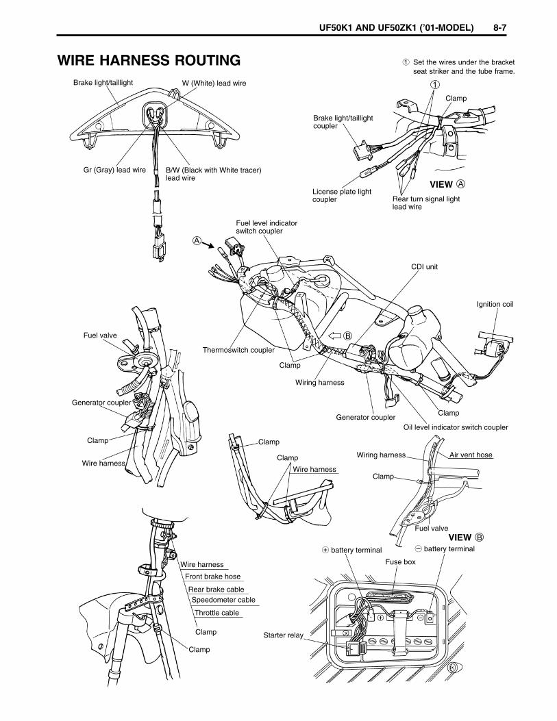
UF50K1 AND UF50ZK1 (’01-MODEL) 8-7
Brake light/taillight
Brake light/taillightcoupler
License plate lightcoupler
W (White) lead wire
Gr (Gray) lead wire B/W (Black with White tracer)lead wire
Fuel level indicatorswitch coupler
CDI unit
Thermoswitch coupler
Clamp
Clamp
Clamp
Air vent hose
Generator couplerOil level indicator switch coupler
Ignition coil
Clamp
Clamp
Clamp
Clamp
Clamp
Wire harness
Wire harness
Wire harness
battery terminal battery terminal
Fuse box
Fuel valve
Starter relay
Front brake hose
Rear brake cableSpeedometer cable
Throttle cable
Generator coupler
Fuel valve
Rear turn signal lightlead wire
VIEW
VIEW
Clamp
Wiring harness
Wiring harness
WIRE HARNESS ROUTING 1 Set the wires under the bracketseat striker and the tube frame.
188
Prepared by
Motorcycle Service Department
2nd Ed. March, 2001
1st Ed. April, 2000
Part No. 99500-10491-01E
Printed in Japan
Printed in JapanY K1


![[SUZUKI] Manual de Taller Suzuki Gran Vitara](https://img.pdfslide.us/doc/110x75/56d6bceb1a28ab30168bfdfc/suzuki-manual-de-taller-suzuki-gran-vitara.jpg)