Embed Size (px)
Citation preview

Sustaining the grid of the futurewith SG3125HV-30

AIM AND SCOPE
2
Through this webinar we will deep into the new features provided by the last generation Central Inverter SG3125HV-30, especially the ones focused on grid support.
General features of this central inverter will be shown, as well as available power block sizes and setup
General grid support features will be described, including the procedure for validating last generation grid support algorithms
DC coupling possibilities and applications will be introduced
Handover to Inaccess to show real onsite applications worldwide, making this central inverter + Power Plant Controller-Energy management system the key to success in the complex scenarios that will appear in a close future

SG3125HV: FEATURES & PLANT SETUP

INTRODUCTION
4
SG3125HV-30 is the last generation of the widely used SG3125HV family 1500Vdc Central Inverter
Central Inverter technology has substantially been developed also over the last 5 -10 years.
• Lower cable loss
• Higher system efficiency
• Lower system cost
• Simpler system
• Lower system cost
• More stable grid control
Power density DC voltage increase
1MVA, Indoor, 1000Vdc 3,4MVA Outdoor, 1500Vdc

GENERAL FEATURES
5
• 10% overloading up to 45ºC 3437kVA
• 2 MPPT per inverter
• IP65 Inverter
• Max. Efficiency 99%, Euro. efficiency 98.7%
• DC/AC ratio up to 1.8
• 24h online AC insulation monitoring
• Reactive power response time <30ms
• SCR≥1.2 stable operation in extremely weak grid
• Built-in ESS interface,support PCS operating mode

BLOCK LAYOUT
6
Plug&Play Solution
Minimum Civil Works
Includes Auxiliary Transformer up to 30kVA
Outdoor concept (except RMU cubicle)
SG6250HV-MV All in one with 2xSG3125HV-30
SG3125HV-MV-30 solution with 1xSG3125HV-30

PLANT DESIGN
7
POWER BLOCK 6,8MW
The perfect fit for
large utility and Floating PV

PLANT DESIGN
8
SG6250HV-MVCombiner Box
PVS-24MH
iSolarCloud
Smart Control Unit
• All-in-one , highly integrated design
• Max. 48 inputs,DC/AC ratio up to 1.8
• 4 MPPT, independent operation
• PVS-24MH Combiner Box
• 24 inputs,positive & negative fuse
• SMC enclosure,C5 & IP67 protection
• Unified communication interface, easy
O&M
• Remote monitoring-iSolarCloud,

SG3125HV-30: GRID SUPPORT

RESPONSE TIME
10
• Response time verified by 3rd party
• 30ms for Reactive power
• 140ms for Active Power
• Q at night function
• Easy compliance with EU631 (1-5s for Voltage Control)
Inverter integrated with fast power control module
110/220kV
<30ms
60% Reactive capacity
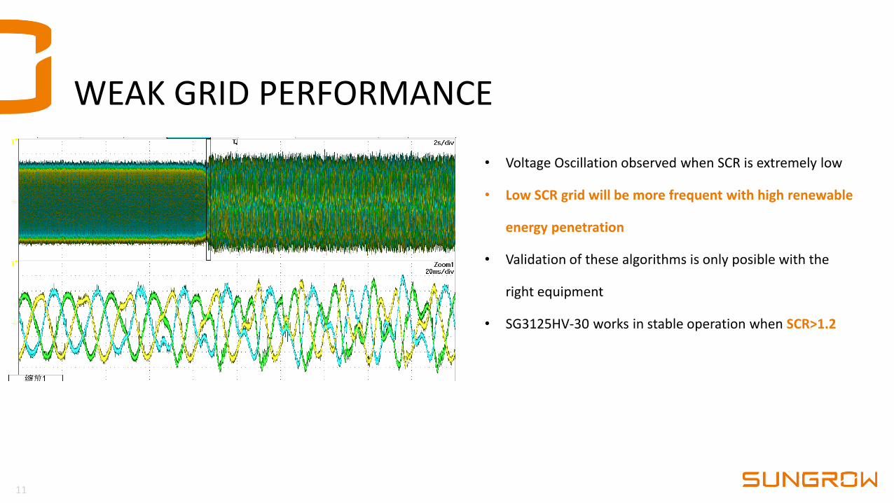
WEAK GRID PERFORMANCE
11
• Voltage Oscillation observed when SCR is extremely low
• Low SCR grid will be more frequent with high renewable
energy penetration
• Validation of these algorithms is only posible with the
right equipment
• SG3125HV-30 works in stable operation when SCR>1.2

HIL VALIDATION SETUP
12
Analog & Digital I/O
PWM
RS485
TCP/IP
a. Host computer
b. Opal-RTreal-time simulator
d. HMI Screen
c. Inverter controller unit
e. PPC
Analogue interface IEC104

HIL MODELLING
13
Adjustable grid
impedance to
simulate different
levels of SCR
Real-time adjustable grid SCR

HIL RESULTS
14
No voltage oscillation overserved when SG3125HV-30 inverter operates at SCR=2 and X/R=3. Inverter is fully functional during both
normal operation (90% power output) and fault ( 90% power, three phase to ground, 95% voltage-dip) conditions. Experimental
waveforms are shown
Voltage, reactive current, active power and reactive power measured at POC during fault
Three phase Voltage at current at POC

DC COUPLING AND APPLICATIONS

MAIN APPLICATIONS- DC COUPLING.
16
Clipping Recapture
Max. power of Inverter
Ramp Rate Control
Power curtailment
Curtailment Recapture
Control the rate of PV power plant, reduce the grid impact
Minimize the power clipping losses for high DC:AC ratio projects
Plant curtailment, energy time shifting
Charging the batteries Charging the batteries
Discharging the batteries Discharging the batteries
Power of PV power plant

MAIN APPLICATIONS- DC COUPLING.
17
Key Features
Bi-Directional Inverter charging and discharging from the grid
No standalone PV/BESS combiner box required
Parallel up-to 3x DC/DC converters
Allows for 1:1 PV/BESS ratio
Each DC/DC contains up to 10x 125kW DC/DC converters
Stops the battery short circuit current at rack level
Futureproof (Add DC/DC + ESS in the future )
Grid
10-35kV
SG3125HV-MV-30
3.125MVA
PV Plant
Batteries SD1250HV
1.25MWdc 3.727MWh

SCENARIO 1. PV EXPORT+BATT CHARGE
18
5MWp
1.25MWdc3.727MWh
Assumptions
⚫ The inverter track MPPT
⚫ EMS/Controller communicate with inverter and
DC/DC. The EMS/controller dispatch the
output.
Conditions
Irradiance = 1000W/m²
PAC* = 3.125MWac
SoC < 100% EMS/Local Controller
PPV
PAC1000W/m²
VDC
5MWp
3.125MW
+1,25MW
[Standard Working Model]

SCENARIO 2. NO PV EXPORT+BATT CHARGE FROM THE GRID
19
5MWp
1.25MWdc3.727MWh
3.125MWac
Assumptions
⚫ No losses
⚫ Irradiance is proportional to IPV
⚫ PDC* and PAC* are EMS control values
Conditions
Irradiance = 0W/m²
PAC* = 1.25MWac
SoC > Lower Limit
PPV
PDC
PACVDC
+1.25MW
+1.25MW
EMS/Local Controller
PDC*
PAC*
0MWp
[Standard Working Model]

SCENARIO 3. MINIMAL PV EXPORT+ PRIORITY BATTERY CHARGING
20
1.25MW
5MWp
1.25MWdc3.727MWh
3.125MWac
Assumptions
⚫ The inverter track MPPT
⚫ EMS/Controller communicate with inverter and
DC/DC. The EMS/controller dispatch the
output.
Conditions
Irradiance = 400W/m²
PAC* = 0.75MWac
SoC < 100%EMS/Local Controller
PPV
PDC
PAC400W/m²
VDC
2MWp
0.75MW
PDC*
PAC*
[Non Standard Working Model]
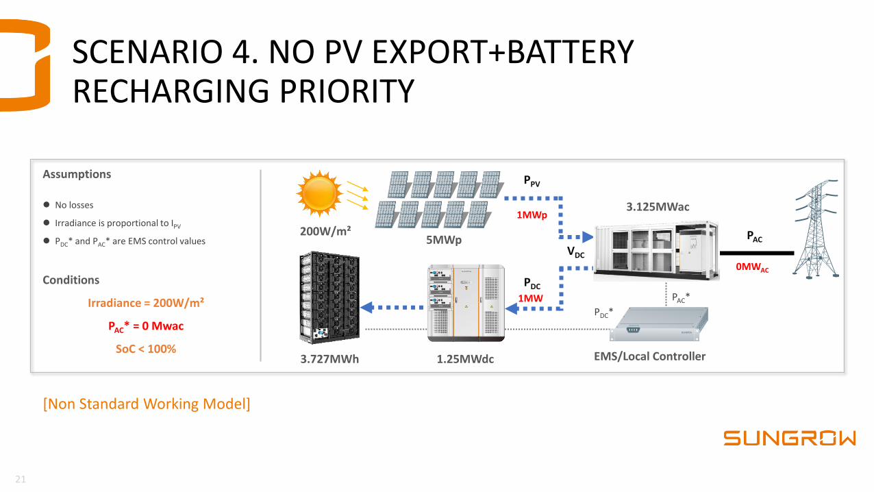
SCENARIO 4. NO PV EXPORT+BATTERY RECHARGING PRIORITY
21
[Non Standard Working Model]
5MWp
1.25MWdc3.727MWh
3.125MWac
Assumptions
⚫ No losses
⚫ Irradiance is proportional to IPV
⚫ PDC* and PAC* are EMS control values
Conditions
Irradiance = 200W/m²
PAC* = 0 Mwac
SoC < 100%
PPV
PDC
PAC200W/m²
VDC
1MWp
0MWAC
1MW
EMS/Local Controller
PDC*
PAC*

SCENARIO 5. COMBINED PV EXPORT+BATTERY DISCHARGING
22
[Non Standard Working Model]
EMS/Local Controller
5MWp
1.25MWdc3.727MWh
3.125MWac
Assumptions
⚫ No losses
⚫ Irradiance is proportional to IPV
⚫ PDC* and PAC* are EMS control values
Conditions
Irradiance = 400W/m²
PAC* = 3.125 Mwac
SoC < 100%
PPV
PDC
PAC400W/m²
VDC
PDC*
PAC*
2MWp
3.125MW
1.25MW

SUMMARY-DC COUPLING
23
Subsidy Free Era
⚫ Wanting to go beyond the Standard PV designs
⚫ Negative price during the day
⚫ Emerging revenue streams
Network Quality Issues
⚫ Frequency & Voltage fluctuation
⚫ Over Capacity
⚫ Low Short Circuit Ratio
DC
Side
AC
Side
Lack of Grid Capacity
⚫ Increased connection cost
⚫ Saturated grid
⚫ Expensive infrastructure upgrades
⚫ Enhanced Grid support functionality –Reducing the need for grid reinforcement works
⚫ Exporting both PV and ESS -Maximizing the Grid Connection Agreement
⚫ Ramp rate control and Capacity Firming
⚫ De-risking energy loss during plant curtailment – Utilization of Storage
⚫ Overall efficiency of the solution is increased –Compared to a traditional AC co-located system
⚫ Global reduction on plant cost - Making DC/DC solution more viable
⚫ Export energy at peak revenue earning times –Maximizing the site potential
SG3125HV-MV-30 Plus SD1250HV

CONCLUSIONS
24
DC
Side
AC
Side
Main factors that all PV inverters must have for the new era
Compact design and high power density, reducing the space needed for the inverter station and the installation time for a lower system cost
Advanced grid support features, validated in laboratory as much closer to reality as possible (HIL)
Compatibility with Energy Storage Systems, to implement all the requests that will be needed sooner than expected.

THANK YOU!