Embed Size (px)
Citation preview

C O N T E N T S
Site address
CGG Building, 12-14 Crompron Way, Crawley
Sustainable Design and
Construction Statement
Prepared by
Bespoke Builder Services Limited
For
Kier Property
Date
August 2015
ENV 37384
HEAD OFFICE
Teaselwood Barn Lamberhurst Vineyard Furnace Lane, Lamberhurst Tunbridge Wells, Kent TN3 8LA
01892 891400 www.bbsenvironmental.co.uk
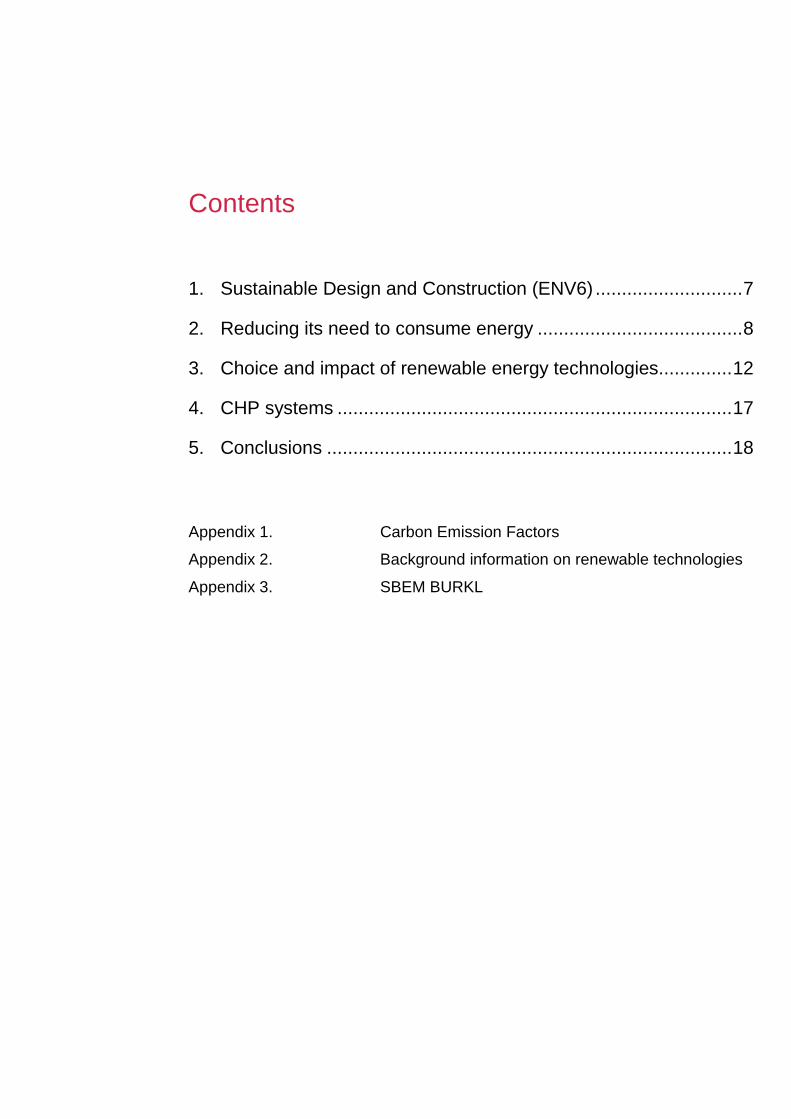
Contents
1. Sustainable Design and Construction (ENV6) ............................ 7
2. Reducing its need to consume energy ....................................... 8
3. Choice and impact of renewable energy technologies.............. 12
4. CHP systems ........................................................................... 17
5. Conclusions ............................................................................. 18
Appendix 1. Carbon Emission Factors
Appendix 2. Background information on renewable technologies
Appendix 3. SBEM BURKL
C O N T E N T S
About Bespoke Builder Services Ltd
Bespoke Builder Services Ltd is a construction consultancy specialising in sustainability, energy
conservation and the application of renewable energy technologies. As a consultancy we do not
sell products, so we are able to take an objective view of a development to assist developers in
incorporating the most cost effective and practical solutions.
Our range of services includes specialist pre-planning reports, energy consumption calculations
for Building Regulations purposes, and broader environmental and sustainability studies and
reports and BRE EcoHomes and Code for Sustainable Homes assessments. Our team of
consultants includes registered SAP Assessors, registered Code Assessors, Planning
Specialists, Renewable Energy Specialists, Chartered Engineers
and Chartered Surveyors.
A sister consultancy is a Corporate Approved Inspector – one of the few approved to provide
Building Control services in the residential sector, and where necessary we are able to draw on
this additional expertise to ensure that all advice given in respect of energy conservation and
sustainability will also meet all other constraints imposed by the Building Regulations.
Established in 2001 by two directors with many years experience in the construction industry,
and latterly, with the NHBC, the practice has grown steadily since, and to date has carried out
hundreds of EcoHomes assessments, and many thousands of SAP assessments. By applying
this expertise to assist developers to understand and meet the new obligations for energy
conservation and on-site renewable energy systems, we are able to help ensure that these
vitally important issues are addressed in a transparent way, where the needs and
responsibilities of all the stakeholders are fully respected.

Report prepared by: Chris Armstrong BSc LCEA171023
1st September 2016
Assessment type: Planning Application

F O R E W O R D
i. Foreword
The impact of human activity on the resources and ecosystems of our planet, and the need to
live within our means has been understood by peoples around the globe from time immemorial.
Yet somehow, in the enthusiasm of industrialisation, with the vast benefits it has brought in
living standards, health, longevity and personal freedom, the understanding of this need, and
the willingness to respect it, seems to have been lost both by individuals and governments.
Only now, at the beginning of the 21st Century, is society moving to a stage where the warnings
long sounded by campaign groups and lone experts are being heeded by governments and
other statutory authorities, and are actually informing real, practical, public policy that is affecting
how we live, and how our communities develop.
In responding positively to the lead taken by the statutory authorities, developers are showing
that if they are given a practical and consistent framework, with adequate time to develop the
knowledge and expertise required, they are ready for the challenge – ready to play their full part
in achieving the transformation that society must achieve – to live more sustainably.

ii. Introduction
This Sustainable Design and Construction relates to the development proposed by Kier
Property in respect of CGG Office Development, 12-14 Crompton Way, Crawley. Kier Property
have prepared a planning application to construct a three storey office building.
This Statement contains an energy demand assessment that shows how the proposals include
efficiency measures that reduce the total carbon dioxide emission and the total energy demand
of the building.
It also assesses which renewable technologies are appropriate for the site, and which the
design team propose to incorporate.
It looks at the possibility of connecting to existing energy networks, and highlights where certain
areas of BREEAM with look to address the reduction of carbon emissions through the
construction phase. The BREEAM Pre-assessment that is submitted part of this planning
application will discuss how the internal water installation will reduce the total water demand in
detail.

E N E R G Y S T A T E M E N T
1. Sustainable Design and Construction (ENV6)
Proposals for new non-domestic buildings should achieve adhere to BREEAM Excellent (for
water and energy credits) where technically and financially viable.
All development, including the alteration and extension of existing buildings, should consider
how it may achieve the following sustainability objectives:
In relation to carbon:
I. Take an active approach to reducing its need to consume energy;
II. Utilise renewable and low carbon energy technologies where appropriate;
III. Look at ways to improve the existing building when adding improvements or extensions;
IV. Minimise the amount of carbon emitted throughout the implementation and construction
process and ensure any existing embedded carbon onsite is retained;
V. Consider Support the establishment and integration of district energy networks within
heat priority areas or near potential sources of waste energy and consider connection or
futureproofing developments for connection (see Policy ENV7);
For other locally-specific Climate Change issues relating to Crawley, all development should
consider how it will:
VI. Tackle the serious water stress in the borough (see Policy ENV9);
VII. Cope with future temperature extremes, and ensure it does not unduly increase the
impact of heatwave events.
2. Reducing its need to consume energy
This chapter contains details of the energy efficiency measures being incorporated in the
development and limiting the demand for space heating/cooling and electricity demand for
lighting.
It also includes an overview of possible renewable energy technologies and identifies the
technology most suitable for this development.
It also concludes that five credits under ENE 01 credit in BREEAM will be achieved that
indicates the Excellent level.
Key energy efficient design measures
The development proposals include the provision of enhanced insulation to all heat loss
elements, which exceeds the requirement of building regulations by up to 40% for each
element. High performance heating systems will be incorporated, and the developer will commit
to achieving a low air leakage.
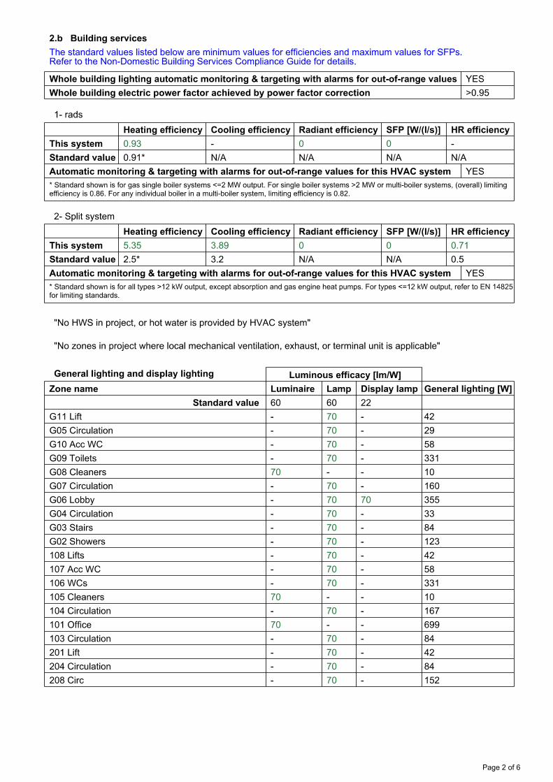
High efficiency lighting design will be incorporated into the design, along with sophisticated
controls which can either switch or dim lighting automatically, dependant on presence detention
and the levels of natural light in the room.
The spaces will also be provided with mechanical ventilation which will incorporated heat
recovery with efficiencies higher than 70%.
Sophisticated metering will be installed which will sub-meter all the services, and provide ‘out of
range’ warnings if unusual readings are detected. This will be accompanied with power factor
correction to the electrical supply.
Summary of proposed heating and cooling systems
The office areas will be provided with heating and cooling which will be provided from a multi-
split system, fuelled by electric air source heat pumps. The selected system will have both high
heating and cooling seasonal efficiencies. The remaining areas will be heating via radiators with
a high efficiency gas boiler.
E N E R G Y S T A T E M E N T
The hot water will be heated by a separate highly efficient gas boiler to enable the gas boiler
that provides heating, to be switched off during the summer months when heating is not
required.
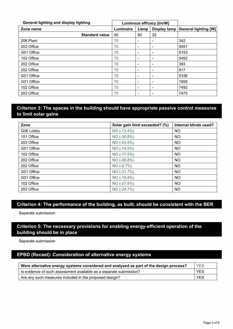
The demands on both the heating and cooling will be minimised through the design of the
building. High levels of insulation are proposed, along with solar control glazing that will limit the
amount of solar gains entering the rooms, whilst keep natural light levels high to reduce the
energy demand for the lighting.
Calculation methodology
The energy demand for the development has been predicted using The Simplified Building
Energy Model (SBEM) 2012 calculation methodology as stipulated within Approved Document
Part L2A: 2013.
SBEM is developed by BRE, and is used for assessing and comparing the energy and
environmental performance of non-domestic buildings.
The calculations generates an estimation of energy consumption per unit floor area, which is
used to determine CO2 emission rates for new buildings in compliance with Part L of the
Building Regulations.
SBEM produces a Building CO2 Emission Rate (BER), which is an estimation of the annual
emissions per unit floor area for space heating, water heating, ventilation and lighting, less the
emissions saved by energy generation technologies, expressed in kg/m2/year. The BER is the
element that are reviewed to ensure each dwelling is compliant with building regulations.
The building regulation criterion is that the BER is no greater than the Target CO2 Emission rate
(TER) based on a notional building of the same size and shape. The TER is estimated using a
set of reference values for the building fabric and heating system, as stipulated within Approved
Document Part L2A.
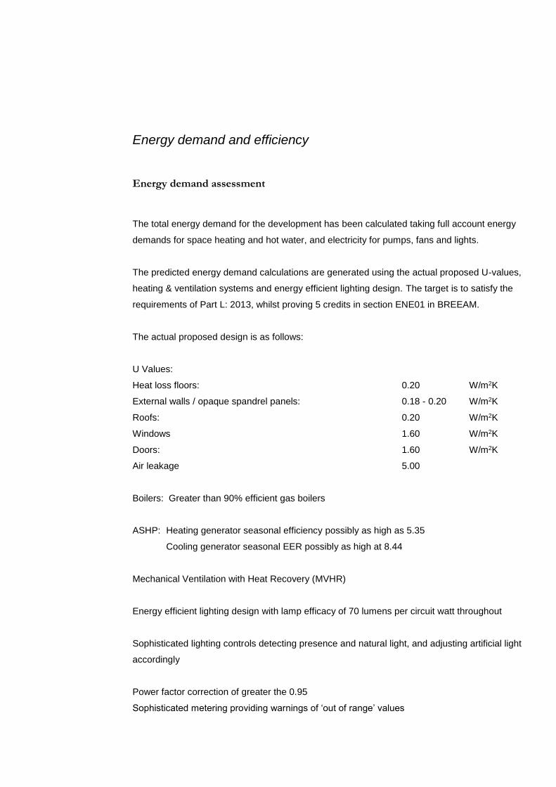
Energy demand and efficiency
Energy demand assessment
The total energy demand for the development has been calculated taking full account energy
demands for space heating and hot water, and electricity for pumps, fans and lights.
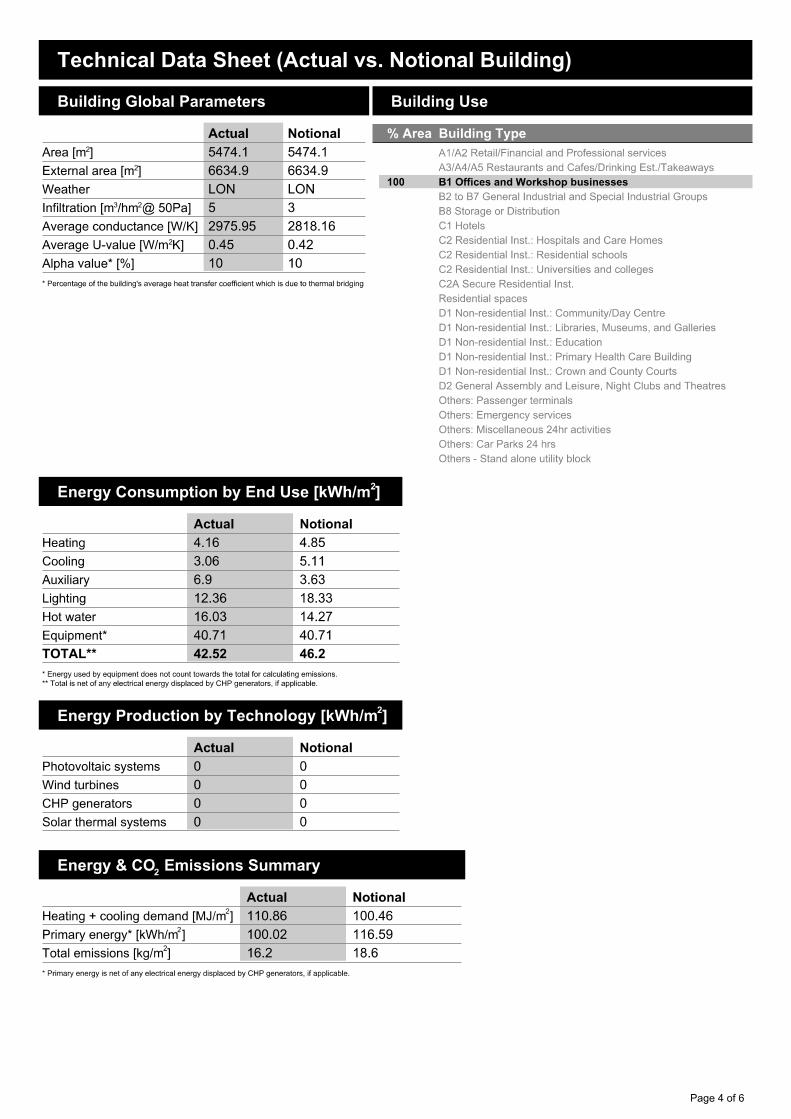
The predicted energy demand calculations are generated using the actual proposed U-values,
heating & ventilation systems and energy efficient lighting design. The target is to satisfy the
requirements of Part L: 2013, whilst proving 5 credits in section ENE01 in BREEAM.
The actual proposed design is as follows:
U Values:
Heat loss floors: 0.20 W/m2K
External walls / opaque spandrel panels: 0.18 - 0.20 W/m2K
Roofs: 0.20 W/m2K
Windows 1.60 W/m2K
Doors: 1.60 W/m2K
Air leakage 5.00
Boilers: Greater than 90% efficient gas boilers
ASHP: Heating generator seasonal efficiency possibly as high as 5.35
Cooling generator seasonal EER possibly as high at 8.44
Mechanical Ventilation with Heat Recovery (MVHR)
Energy efficient lighting design with lamp efficacy of 70 lumens per circuit watt throughout
Sophisticated lighting controls detecting presence and natural light, and adjusting artificial light
accordingly
Power factor correction of greater the 0.95
Sophisticated metering providing warnings of ‘out of range’ values

E N E R G Y S T A T E M E N T
Heat loss element thermal performance has been improved by between 20% (roofs and floors)
to 40% (Walls). This performance improvement is further enhanced by the reduction in air
leakage (by 50%) and inclusion of highly efficiency services. The results with the energy
efficiencies are as follows:
Total Scheme Carbon Emissions: 88,681 kgCO2/yr
Total Scheme Energy Demand: 232,759 kWh/yr
The results for SBEM calculations are summarised in Appendix 3.
3. Choice and impact of renewable energy technologies
The design team are proposing to provide heating and cooling to the office via air source heat
pumps. These are of efficiencies greater than 400% and therefore deliver four times as much
energy as they consume.
Overview of renewable energy
Renewable energy is defined as energy derived from energy flows that occur naturally and
repeatedly in the environment. It may be contrasted with energy sources that can be depleted
such as fossil fuels or uranium-238-based nuclear power. It therefore follows that the commonly
used phrase “equipment to generate renewable energy” is an oxymoron since renewable
energy cannot be “generated” – the true function of the technology is to harness a natural
energy flow.
Renewable energy technologies, with a couple of exceptions, all utilise energy from the sun –
either directly or indirectly, the exceptions being true geothermal2, which uses heat from the
earth’s core, and tidal / marine current electricity generation which uses the gravitational forces
between the earth and the moon, (although some marine currents are also greatly affected by
solar energy). Insofar as this study is only concerned with practical options for on-site renewable
energy, these options are not considered further. The remaining range of “solar” technologies
are however vast, and some would not even appear to be solar on superficial inspection. They
can be summarised as follows:
Solar thermal – direct heating of water for space heating or domestic hot water;
Photovoltaic – direct generation of electricity from sunlight;
Hydroelectricity – use of solar (water cycle) driven3 water flows to generate electricity;
Wind turbines – use of solar driven air movement to generate electricity;
Heat pumps – extraction of solar heat from the earth, atmosphere or water bodies;
Bio-fuels – combustion of solid or liquid bio-fuels to produce heat or electricity;
The technologies, and their potential application to this site are discussed in more detail the
following sections. However, one further pertinent point must be made. The reason for adopting
renewable energy technologies is to reduce greenhouse gas emissions – mainly carbon
dioxide. And none of the technologies are wholly “zero carbon”.
E N E R G Y S T A T E M E N T
This is because when the whole life cycle is taken into account some energy has to be put into
every system to manufacture and maintain the equipment (which has a finite life) or to operate
the equipment, and generally at present this energy is derived from non-renewable sources.
Examples include the energy needed to refine and process the silicon used to manufacture
photovoltaic panels, the diesel fuel used to transport wood pellets to the development and to
power the wood processing machinery, and where applicable to bio-fuels, the energy used to
manufacture the fertilizers needed to maintain soil fertility.
Finally, due to the dynamic and innovative nature of the renewable energy technology industry
even apparently similar products can differ in vital practical details which means that detailed
design of installations must be undertaken by experts, often working closely with the product
manufacturers, as virtually no two products are identical or interchangeable.
The following sections contain a summary of each possibly-applicable technology, and a
comparison of the advantages and disadvantages of technologies relevant to this development.
Additional information on each technology is provided in the Appendices.
Solar thermal panels
A typical solar thermal (hot water) panel can provide 400 kWh of useable hot water per year for
every square metre of panel. Since this energy would replace gas, the reduction in carbon
dioxide emissions would be 78 kgCO2/m2.
For reasons detailed in section 6, solar water is not considered to be feasible for this
development, given the inconstant levels of hot water demand. If the design team is considering
using roof space to provide a form of renewable technology, it is considered than photovoltaic
panels would be a better use of the available roof space.
Photovoltaic panels
Photovoltaic panels are panels of semiconductor material that produce electricity when exposed
to light. They are connected to the building electricity supply via a device called an inverter
which converts the output to a form which is compatible with the mains electricity voltage and
frequency. This also allows excess electricity to be exported at times when the instantaneous

demand from the dwellings is less than that being produced by the panels. This ensures that all
the electricity produced is used and achieves a reduction in carbon dioxide emissions. For all
purposes relating to Planning, the exported electricity is by convention treated as if it were used
on site. In general with flats the inverters are connected to the Landlord’s electrical intake where
they provide power for lifts, lighting, booster pumps and any other communal demand. With
regard to the Building Regulations convention is that the output is treated as if it was connected
to the individual flats, and shared pro-rata to flat floor area. This way the output and resulting
carbon dioxide emission saving is reflected in the results.
The output of photovoltaic panels is generally specified as kW peak, or kWp. The panel area
required to produce an output of 1 kWp varies with panel technology, but a typical south facing
1 kWp mono-crystalline panel would have an area of 6-7m2 and produce an annual electricity
output of approximately 843.2 kWh (45 deg tilt). This output would result in a reduction in carbon
dioxide emissions of 446.0528 kg.
Photovoltaic panels are considered to be feasible renewable energy source for this
development.
Hydroelectricity
Clearly micro-hydroelectricity is not applicable to this development.
E N E R G Y S T A T E M E N T
Wind turbines
Micro wind turbines produce electricity and can be grid-connected in the same way as
photovoltaic panels. Roof mounted micro wind turbines could be installed, and if aesthetic
considerations are set aside it might be technically feasible to install up to two turbines with a
rotor diameter of 3.5m and a hub height above the building of 6.5m.
However the electricity output of such an installation would be limited due to the limited wind
resource and significant wind shadowing and turbulence that typically occur in urban locations.
Therefore this form of renewable energy is not considered to be feasible.
Heat pumps
Heat pumps collect low temperature heat from renewable sources and “concentrate” it to a
usable temperature. Fossil fuel based (grid) electricity is generally required to operate the
pumps and the renewable component of the output is therefore by convention taken as the
difference between the output energy and the input energy. A typical heat pump will deliver 4
kWh of useful energy for every 1 kWh of input energy. A heat pump operating in this way would
therefore be deemed to have delivered 3 kWh of renewable energy.
In urban locations ground source heat pumps collect heat from boreholes. These are typically
up to 100m deep and have to be spaced at least 6m apart to avoid over-cooling the ground. A
typical borehole can deliver a maximum output of 4kW of heat.
In contrast, air source heat pumps avoid the need for boreholes so could be installed in the
central plant.
Heat pumps are considered to be a feasible source of renewable energy for this development.
Note 2: Ground source heat pumps are sometimes described as “geothermal”, however most simply extract solar energy stored near the Earth’s surface. Note 3: This may be compared with “pumped storage” systems such as Dinorwig in North Wales where water is pumped to an upper storage lake during periods of low electricity demand and released to generate electricity when needed during times of peak demand.

Bio-fuels
In the UK at present commercial bio-fuels are confined in the context of this development to
either wood pellets or wood chips. These fuels are known as biomass. Wood pellets are
generally preferred as they have a higher energy density, produce less ash, and are much
easier to handle.
A pre-requisite for biomass is that an adequate amount of space is available to store the fuel.
For this development the proposal is to locate the plant on roof level. This would make it
problematic to receive deliveries of wood pellets or wood chips.
For this reason it is considered infeasible to incorporate Bio-fuels.
Renewable energy options – conclusions
The developers preferred renewable technology is to use air source heat pump to deliver the
heating. These pumps can be also used to deliver cooling to the office spaces when required.

E N E R G Y S T A T E M E N T
4. CHP systems
Combined Heat and Power (CHP) and Combine Cooling Heat and Power (CCHP) or
Trigeneration Systems are recognised as a very desirable way of reducing energy wastage and
resulting carbon dioxide emissions. While generally operating on fossil fuel, mainly natural gas,
their advantage is that the waste heat normally associated with electricity generation (the
reason for the familiar “cooling towers” at power stations) is put to good use providing space
heating and hot water. This means that the overall fuel efficiency can be increased significantly
– typically to above 80% compared to 30 – 40% for grid electricity. The main effect is to
approximately halve the carbon dioxide emissions associated with electricity use on the
development for all the electricity produced by the CHP plant. This can have a dramatic effect
on total emissions.
Generally a CHP system is best suited to development which has a high hot water demand. For
example, a mixed use development which incorporates dwellings and commercial buildings.
The hot water demand associated with such a development will stay constant all year round,
unlike heating demand which will reduce significant in the summer months. Therefore with this
high and constant demand, the CHP resulting energy waste can then be used as described
above.
Whilst the demand for hot water in this development appears to be a reasonable proportion of
the overall energy demand, it is not considered to be large enough for a CHP system to be
feasible. In addition, the demand for hot water in this development is likely to be in the morning
only, when employees who choose to cycle to work, use the showers. Therefore the demand
will only be reasonable for short period of time. Therefore the heat generated form such a
system is unlikely to be utilised, and therefore going to waste.
For the above reasons CHP is not regarded as viable on this development.
Establishment and Integration of District Energy Networks
It has also been investigated whether there are any local district heating networks located close
to the development. There is one such network proposed within the city centre of Crawley, but
this is not located close enough to the development for a connection to be considered to be
feasible. The development on its own is fairly small therefore establishing new District heating
plant is not considered feasible either.

5. Conclusions
The foregoing report and projected results show that this developments proposals:
Include measures to reduce carbon emissions and energy
Include renewable and low carbon technologies
Satisfy the mandatory required in BREEAM 2014 to reach 5 credits in ENE01
The BREEAM Pre-assessment submitted with this planning application will discuss in more
detail with how internal water installations will minimise the water demand and how the
construction phase amount of carbon emission will be minimised.
A P P E N D I C E S
Appendix 1.
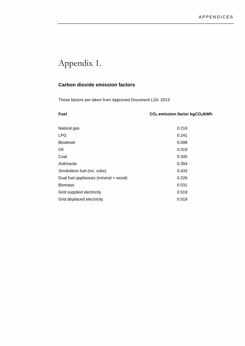
Carbon dioxide emission factors
These factors are taken from Approved Document L2A: 2013
Fuel CO2 emission factor kgCO2/kWh
Natural gas 0.216
LPG 0.241
Biodiesel 0.098
Oil 0.319
Coal 0.345
Anthracite 0.394
Smokeless fuel (inc. coke) 0.433
Dual fuel appliances (mineral + wood) 0.226
Biomass 0.031
Grid supplied electricity 0.519
Grid displaced electricity 0.519

Appendix 2.
Background information on renewable energy technologies
A2.1 Solar thermal panels
This technology is commonly used in residential developments. Solar thermal panels use the
sun’s energy to contribute to the heat energy needed to provide space heating and/or domestic
hot water. They are perhaps the oldest, and certainly the most obvious and easily understood
type of renewable energy technology.
The panels consist of a roof-mounted solar heat collector which can be either a flat plat or tube
system containing water, or a more complex evacuated tube system, which in some cases
utilises “heat pipes”. The systems also include provision to ensure that the water in the panel
does not freeze in winter, and an electric pump to drive the “solar circuit”.
When the system contributes to the domestic hot water supply only, water in the solar circuit is
circulated through the panels and into a separate heat exchanger in the hot water cylinder. The
amount of fossil fuel that can be saved is limited to the amount that would have been used to
heat domestic hot water within the dwelling. If surplus hot water is produced it will be wasted, so
cannot be counted when determining the amount of renewable energy being provided. Since
the results in this report are based on Ofgem data, they include for this effect, although to
remain realistic an upper limit on panel size has to be imposed to reflect the fact that once
panels exceed a reasonable size no further improvement is achieved. This is typically 2m2 to
4m2 depending on dwelling size.
Solar thermal panels can also be used to contribute to space heating using a more complex
arrangement. Essentially the solar heat is used to contribute to heating a “thermal store” – which
is much like a hot water cylinder. Except that it is directly heated to 80ºC by the boiler and the
solar thermal panel, and generally contains two heat exchange coils, one for the central heating
system and one for domestic hot water. Heat stored in the thermal store can thus be delivered
to both the heating system and the domestic hot water supply as required (the domestic hot
water is blended with cold water to reduce the temperature to a safe level). The system has the
added advantage that boiler cycling is reduced (and efficiency increased) as short term heat
demands can be supplied from the thermal store.
A P P E N D I C E S
The disadvantage is that most heat is available from the solar thermal panel in the daytime in
summer generally when there is no heating demand. And in winter, when there is greatest
demand, the solar thermal panel output is lowest and typically will be fully utilised supplying
domestic hot water alone.
Similar systems can also be used on community heating systems which are mainly used on flats
but can be used with houses. A central boiler heats a thermal store and solar thermal panels
can contribute heat. Hot water is then distributed to each dwelling via “heat mains” where a heat
exchanger with a heat meter is used to supply the heat to the local system within the dwelling. It
is estimated that this will increase the usable heat from the panels by up to 20% since at certain
times of the year, mainly spring and autumn, the panels will produce more heat than is needed
for hot water and this can contribute to the space heating demand.
The principle disadvantage with solar thermal systems is that the heat cannot be stored for long
periods, and unlike electricity cannot be exported when surplus is available. Further
disadvantages are that unless a community heating system is to be provided, each dwelling
needs a separate roof-mounted panel with pipework routed to the dwelling, and with larger
blocks of flats, this can pose severe problems. Despite these issues, solar thermal panels have
a useful role, particularly where a simple, modest cost system is required.
In respect of potential to reduce carbon dioxide emissions, there are two issues. First, the
displaced energy is generally gas, with a modest carbon dioxide emissions factor of 0.194
kg/kWh. This simply reflects the fact that had the solar energy not been collected the heat would
have been delivered by a gas boiler at this relatively low emissions rate. (See Section 5.2 for
details of the higher emissions rates used for grid electricity and displaced grid electricity). The
second point, often overlooked, is that most systems use additional electricity to circulate the
water in the solar circuit. In an example where a 4 m2 solar thermal panel is installed on a 90 m2
3-bed house, the panel will contribute 943 kWh/year of energy and therefore reduce the carbon
dioxide emissions by 943 x 0.194 = 183 kg/year. However SAP predicts that the solar circuit
pump will use an additional 75 kWh/year of electricity and this will add back 75 x 0.422 = 32
kg/year to the emissions total, i.e. reducing the saving by 17.5%. Some systems do use small
photovoltaic panels to drive the solar circuit pump but these are not common. This issue serves
to illustrate in a practical way the assertion made in earlier in the report that even in use, most
renewable energy technologies are not “zero carbon” and typically use some fossil-fuel based
energy to facilitate their operation.

A2.2 Photovoltaic panels
Photovoltaic technology – the direct generation of electricity in semi-conductor panels when
these are exposed to sunlight, is not new. The first PV cells were demonstrated in the late
1950s although the physics had been known since the beginning of the 20th century. There are
three types of modern silicon semiconductor panels; monocrystalline; polycrystalline; and thin
film; plus a new technology that involves screen printing non-silicon nano-technology inks on to
a flexible substrate. In many ways these products are similar, with outputs ranging from 50 to
150 kWh/m2. However the main thrust of development now is towards reducing cost, with
potential cost reductions of up to a factor of 10 being claimed for the nano-technology systems
once they are in volume production.
Photovoltaic panels are conceptually straightforward. The panels produce “zero carbon"
electricity that is used in place of grid electricity, and the carbon dioxide emissions saved are the
emissions that would have occurred had the electricity been produced by a power station
feeding the grid. And because photovoltaic panels produce electricity, they substitute for the
energy type that has the highest emissions of carbon dioxide per kWh of delivered energy of
any domestic fuel type. This means that although the energy output can be quite modest the
carbon dioxide emissions saved can be very worthwhile.
Photovoltaic panels inevitably produce most electricity when it is not needed in a domestic
context. This is in the daytime in summer. They can still be used however because of the
concept of "grid storage". They are connected to the grid via an "inverter" and any excess
electricity is "exported" so that someone else can use it, and a power station, perhaps hundreds
of miles away, will burn a little less oil. Then later, when the domestic demand exceeds the
panel's output, the shortfall is drawn from the grid as needed. Whilst there are finite losses and
inefficiencies in this approach, it does work, and it is generally accepted that for virtually all
purposes, any exported electricity is treated as if it was used on site when determining the
carbon dioxide emissions savings.
Furthermore, the carbon dioxide emissions factor used for displaced electricity (i.e. that “saved”
from being produced by the grid network) by virtue of the output from photovoltaic panels (and
any other micro-generation system) is actually higher at 0.568 kg/kWh than the factor for
electricity drawn from the grid which is 0.422 kg/kWh. This is because the electricity fed into the
grid reduces the instantaneous demand from the “marginal” generating plant, i.e. the fast
response gas and oil fired stations, as studies have shown that this plant has higher average
emissions than the base load plant.

A P P E N D I C E S
In terms of practical application there are two main issues – cost per kWh generated and
physical size. In that the total annual predicted carbon dioxide emissions of from a 2-bed well
insulated flat are around 1500 kgCO2/yr, reducing this by 20% using typical panels would
require a panel area of approximately 4.5m2 and cost approximately £4,000. However, if the
claims for the latest technology are realised the dramatic cost savings would make a real
difference to financial feasibility, although the issue of available roof area will continue to pose a
problem on the denser schemes of flats.
Photovoltaic panels also have certain siting constraints. To produce the maximum output they
should face due south, although south-east to south-west is certainly acceptable, and even east
or west will be acceptable if the angle of inclination is no more than 20º. When not in direct
sunlight, but shaded by obstacles such as adjacent buildings or trees, the output of the affected
panel is significantly reduced. And because groups of panels are connected together electrically
in "series" a reduced output from one panel will reduce the output from all the panels in the
group. This means that it is particularly important to avoid over-shading.
However photovoltaic panels have many advantages. They are clean, silent, reliable, low
maintenance, and are easy to install. They also have a very long life – up to 40 years – which is
at least double that typically quoted for other technologies. So while being relatively expensive
in terms of capital cost per kWh, they perform much better when measured in terms of cost per
kgCO2 saved, and in “whole life” cost terms, larger installations can perform the best of all
technologies, even at current prices. And if the projected cost reductions materialise, they could
prove to be the dominant technology of the future.
In addition, and unlike most solar thermal panels, and most other renewable energy
technologies, photovoltaic panels are “zero carbon” in use. They simply produce electricity when
exposed to sunlight. However the situation is rather different when the carbon dioxide emissions
are determined using a “whole life cycle analysis” approach that includes the energy and other
greenhouse gas emissions associated with panel manufacture (panel manufacture uses large
amounts of electricity and greenhouse gases such as SF6 which has a Global Warming
Potential 24,000 time greater than CO2). Studies14 have shown that when analysed in this way
the effective whole life emissions rate of a typical photovoltaic panel is approximately 0.050
kgCO2/kWh compared to the much lower rates of 0.008 kgCO2/kWh for wind turbines and 0.025
kgCO2/kWh for biomass systems.
Note 14: Photovoltaics Energy Payback Times, Greenhouse Gas Emissions and External Costs, 2004-early 2005 status – Vasilis Fthenakis and Erik Alsema (January 2006).

So although in the UK, SAP does not take into account “embodied” emissions, they are real,
and for photovoltaic panels, substantially larger than for most other technologies. Of course,
once the panels are manufactured in plants powered by renewable energy, this problem will be
substantially reduced, and the new nano-technology systems are far less energy intensive.
A2.3 Hydroelectricity
The utilisation of “water power”, together with “wind power” is generally recognised as having
facilitated the early stages of the industrial revolution in Europe. Water wheels were simple to
manufacture and produced high torque without gears, and simple gears could be used to
increase speed. Water power was, unlike wind power, controllable, and subject to a sufficient
water level in the “mill pond”, was available on demand. Water power was of course used to
grind wheat to produce flour, but also powered many types of machinery including bellows for
blast furnaces, and hammer mills used to produce wrought iron. Today, large hydroelectric
schemes are still very important energy sources in many countries, although in the UK only
0.8% of the electricity demand is produced in this way, mainly because there are very few
suitable sites. The Government estimates that if all the rivers and streams in the UK could be
harnessed the output would still only be 3% of the total demand, so while local schemes can be
important, strategically, this is one of the less important technologies.
Micro-hydro is the term used for very small schemes, although it is applied to any scheme
producing less than 1 MW. On-site micro-hydro is clearly totally dependent on the availability of
a suitable river or stream that could be utilised in an environmentally acceptable way, and
produce a worthwhile output, and such availability is so limited in typical urban sites as to make
this a technology that is generally of no relevance.
The extraction of energy from flowing water will by definition reduce its velocity and change
water levels, and introducing such changes even to a canalised urban river can have both
upstream and downstream impacts. And where the site has a natural ecology the local impacts
can be far greater and the necessary mitigation difficult to achieve. So in conclusion, the most
likely instance where a micro-hydro installation might be possible is one where an existing or
historical site can be utilised but these are very rare – potential mill locations were valuable
assets and very few were not utilised by landowners. One such example is the Guildford Toll
House project where a hydro turbine originally installed 1897 to drive pumps has been
renovated and converted to generate electricity. Importantly the turbine house and river-bed
structures were still in place, but even then the project cost was £340,000 and it will only supply
50 houses with electricity.

A P P E N D I C E S
A2.4 Wind turbines
The general principles of operation of small scale wind turbines are straightforward, and
windmills are probably one of earliest ways that mankind harnessed natural energy flows and
put them to practical use. However while conceptually simple, wind turbines present complex
challenges both in technical and planning terms, and cannot be considered a simple option.
Considering in the first instance only the technical issues, it will first be necessary to establish
whether a site has an adequate wind resource. Preliminary checks can be made using the DTI
wind speed database and a site with a theoretical average wind speed of at least 5 m/s at 25m
above ground level can be suitable. Other relevant issues are the amount of local wind
shadowing and turbulence likely to be produced by nearby buildings and trees and whether the
site is open in the direction of the prevailing wind. In practice, even on a promising site these
issues mean that to have any confidence that a worthwhile amount of electricity could be
generated and thereby validate an investment decision it is necessary to carry out extended
wind speed measurements, typically over a full year.
In the normal absence of valid wind data at the beginning of a project some guidance is
becoming available on the reduction in output typically seen on a sheltered urban site compared
to manufacturer’s wind-tunnel data. This can be illustrated by reference to the data for a 1.5kWe
unit with a rotor diameter of 2.1m. In a rural environment with an average wind speed of 8 m/s,
such a unit would produce 2,785 kWh/yr, and reduce carbon dioxide emissions by 1,633 kg. In
contrast, on an urban site where the wind speed is just 4.8 m/s it would produce only 62 kWh/yr,
and reduce emissions by just 35 kg. A single turbine of this type would therefore reduce the
emissions of a single 2-bed flat by just 4%.
While this technical review indicates that wind turbines are very unlikely to be worthwhile on
urban sites, in addition, other issues have to be considered. Clearly the overriding issue is the
impact on the visual amenity of the site and surroundings. Opinions are generally divided on the
aesthetics of wind turbines, but in many cases Local Planning Authorities are reluctant to grant
consent for multiple or larger turbines. In addition, larger slower turbines while being quiet can
create visually disturbing reflections and are generally considered to be unacceptable for
installation close to or within residential developments. The exception to this is where larger
micro wind turbines can be installed on the top of high rise towers where there is a good wind
resource and where visual impact is minimised.
So while large wind turbines installed in “wind farms” in exposed locations and increasingly off
shore, can and are providing a substantial amount of the UK’s current renewable electricity, the
use of micro wind turbines on small residential developments is of questionable value, and is
frequently no more than a token gesture.
A2.5 Heat pumps
Heat pumps are perhaps the least understood renewable energy technology. All heat pumps
operate in a similar way and are devices that collect naturally available low temperature heat
and “concentrate” it so that it can be put to good use.
To understand how a heat pump works it is first necessary to appreciate the difference between
“heat” and “temperature”. “Heat” generally means heat energy and is expressed in the SI unit
the Joule, and 1 Joule is 1 watt of power acting for 1 second. Temperature is a measure of the
degree of hotness of coldness of a substance, and there is a theoretical “absolute zero”
(expressed as 0 Kelvin or -273.15 ºC) – the temperature at which all molecular motion ceases.
Now the amount of heat that has to be absorbed by a given amount of a substance or extracted
from it to change its temperature by a given amount depends on the molecular structure of the
substance, and is known as its heat capacity. The specific heat capacity of water is 4.18
kJ/kg/ºC and that of dry soil is approximately 0.80 kJ/kg/ºC. A further important aspect of the
relationship between heat and temperature is that heat will only move if there is a temperature
difference, moving from a zone of higher temperature to one of a lower temperature and the rate
at which heat will move depends on the thermal conductivity of the substance through which it
has to move.
Most heat in the earth’s natural environment comes from solar radiation and this heat is stored
in the earths crust, in water bodies such as oceans, and in the atmosphere. Most of this heat is
at a temperature which is too low to be directly useful – the typical temperature 2m below the
surface of the earth in temperate zones is 10 – 12 ºC but many humans find this too cold for
domestic purposes such as showers which we prefer to be at 40 ºC, and we like our living
spaces to be controlled to around 20 ºC. But if we could collect 1 kJ of heat from the soil by
cooling 1.25kg of it by 1 ºC it would be enough to heat 239g of water by 1ºC. Now the hard bit is
collecting the heat and moving it to where we want it. What is needed is a device that will cool
say 125kg of soil by 1 ºC, and extract 100 kJ of heat and then use this heat to raise the
temperature of 239g of water by 100 ºC. This would allow us to make a cup of tea! In other
words we need a mechanism that will move heat from one place to another that does not rely on
temperature difference. This device is called a heat pump (or a refrigerator!). A refrigerator
A P P E N D I C E S
moves heat from a cold place, the inside of a well insulated box, to a warm place, the kitchen,
and a heat pump works in the same way. The heat is moved by using the relationship between
pressure and temperature in substances that have liquid and gaseous states. A working fluid is
pressurised and circulated through the system by a compressor. On the discharge side of the
compressor the now hot and highly pressurised gas is cooled in a heat exchanger and gives up
heat to the heating system at around 50 ºC. It condenses into a moderate temperature liquid,
still at pressure. The condensed liquid passes through a pressure lowering device to a second
heat exchanger where it will absorb heat at around 10ºC as it evaporates into a gas. The gas is
then pressurised again by the compressor and it heats up and the cycle is repeated. The key
requirement is that the system, the fluid and the pressures must be arranged so that when
pressurised, the gas temperature exceeds the required output temperature, and that during
evaporation the gas cools to a temperature below the input temperature. This way heat from the
source flows into the cool gas and out from the hot pressurised liquid.
This transfer of heat can only be achieved by constantly pressurising and de-pressurising the
working fluid, and energy has to be put into the system to operate the compressor. The system
works because the amount of mechanical energy needed to run the compressor is substantially
lower than the amount of heat moved. The ratio of mechanical energy input to heat moved is
described by the term coefficient of performance (CoP). The term efficiency should not be used
because technically this would imply that that the heat pump made the heat, which is of course
impossible – it simply moves it from a place and at a temperature where it is not useful to
somewhere where it is useful.
The CoP achieved obviously depends on optimising the system, but it is also affected by the
temperature difference that has to be achieved. This means that a heat pump with an input
temperature of 10 ºC and an output temperature of 40 ºC will operate with a CoP of around 4 to
4.5 whereas reducing the input temperature to -10 ºC or increasing the output temperature to 60
ºC will reduce the CoP to perhaps 2.5. Now whereas it is usually not difficult to ensure that the
output temperature does not get higher than necessary, it is more difficult to ensure that the
input temperature remains constant. The key issue is to ensure that the cooled heat collector
has sufficient area for the required amount of heat to naturally flow from the source. Now the
rate at which that flow will occur depends on the thermal conductivity of the source material as
well as its heat capacity. In terms of renewable energy, all the heat moved by the heat pump is
renewable as it is all generally derived from natural energy flows. However the mechanical
energy used by the pump is generally provided by a motor running on grid electricity. So the
convention is that the renewable component is the difference between the input energy and the
output energy. In energy terms therefore a heat pump with a CoP of 4 will use 1 kWh of
electricity to move 4 kWh of heat, so this would be considered to harness 3 kWh of renewable
energy.
Note: this requirement for input energy is identical in concept to the need for input energy to run
a solar circuit pump on a solar thermal panel, although with solar thermal panels the not
insignificant pump energy is frequently ignored.
In practice there are three potential heat sources: a water body, the ground, or the atmosphere.
In each case a suitable heat collector has to be used – for water, a grid of pipes immersed in the
water; for the ground, pipes buries in trenches near the surface or in boreholes typically up to
100m deep; and for the atmosphere a unit rather like a large car radiator with a fan.
The first of these is generally the best, if it is available. Most water bodies such as lakes have
relatively constant temperatures, and water has a high heat capacity and is highly thermally
conductive so as heat is extracted it will flow quickly through the water and an even temperature
is maintained and no localised cooling occurs. Furthermore, the heat collector can sometime be
located so that convection currents assist in maintaining an even temperature. An equally
satisfactory arrangement can be achieved if the heat is collected from moving water such as a
river, although in this case serious ecological issues can arise.
Using the ground as the heat source is perhaps the most common situation, and here the
situation is more challenging. This is because the heat capacity is lower and the thermal
conductivity is much lower compared to a water body, and of course there are no convection
currents. The situation is helped if the heat collecting pipes are below the water table as the
water improves the thermal conductivity and increases the thermal capacity. However it is
essential that heat is collected from a sufficiently large horizontal or vertical area, and in practice
most urban and suburban systems use boreholes. It is worth noting that although the nominal
ground temperature is 10 - 12 ºC, for the heat to flow through the ground a temperature
difference must exist between the larger mass of the ground and the heat collector. This can be
several degrees, and typically means that the input temperature can be only 5 ºC. Furthermore,
during periods of peak output i.e. in winter it is possible for more heat to be extracted than is
replenished by the natural flow, and this will cause the input temperature to slowly drop. This is
not a problem if during periods of lower output i.e. in the summer, the temperatures fully
recover. If however there is any year-on-year drop, then the temperature will eventually get too
low for satisfactory operation. For this reason it is essential that ground source heat collectors
are specified by experts who understand and allow for the specific site ground conditions, and it
is vital to ensure that the ground is never frozen.
A P P E N D I C E S
Air source heat pumps are becoming increasingly common, and have many advantages
including avoiding the need for boreholes or trenches. The heat source remains the sun, and in
fact much of the heat in the atmosphere (especially at night) is actually solar heat that has been
stored by the ground and the fabric of buildings and other structures and that is slowly released.
Other heat travels in the form of weather systems that bring warm moist air from above the
oceans. The heat collector extracts heat from the air that is circulated though it by the fan.
However as the thermal capacity of air is very low a significant air flow is required. The need for
a fan, and the fact that the heat collector can get somewhat colder than a ground collector,
especially in winter, means that air source heat pumps have slightly lower CoP than other types
– typically around 3.3.
In all three cases described so far the heat pump systems have comprised two physically
separated components: the heat pump and the heat collector. And while the heat collectors
differ according to the heat source, the heat pumps are essentially identical. There will also be a
third component, a hot water storage vessel which stores domestic hot water and often acts as
a thermal store for the heating system. This can either be a separate unit or can be located in
the same enclosure as the heat pump. In these latter cases this combined unit can by means of
stratification achieve a higher hot water temperature whilst operating at a higher CoP. Such a
unit is typically around the size of a large fridge-freezer.
However another option, the ducted air source heat pump is becoming increasingly popular. In
this unit all three components are combined into a single enclosure. The ducting is arranged to
bring external ambient air into the unit where it is chilled and exhausted at a temperature below
that of the external atmosphere. One system has a large cross section direct through-wall duct –
it is designed to be installed in an external corner with large ventilation grills on the two walls at
90º to minimise the risk that the chilled air would be drawn back into the unit. An alternative
arrangement actually connects to the dwelling mechanical ventilation system and uses the
warm air that would otherwise have to be exhausted from the dwelling to maintain internal air
quality. In this latter case it must be stressed that the unit is still a heat pump not simply a heat
recovery device. This is clear from the fact that it operates with a CoP of up to 3.2, whereas the
best heat recovery device can only operate with an efficiency of less than 100% (CoP: 1.0), and
the best available are typically 92% (CoP: 0.92). Indeed, the operation might be better
understood if the dwelling is considered as a “black box system”. The air entering the dwelling
either through ventilation grills or air leakage enters at the outside atmospheric temperature. It is
warmed by mixing with the air in the dwelling and by contact with the internal surfaces. However
the air leaving the dwelling under pressure from the heat pump exhaust fan is colder than the air
outside that initially entered the dwelling. It is this temperature difference that allows the heat to
be extracted and the heat pump to move heat from the outside air to the heating system. In
comparison, a heat recovery system that works on temperature driven heat flows system cannot
cool the temperature of the exhaust air below the temperature of the incoming air (in fact the
exhaust air temperature will always be slightly higher than the incoming air temperature
because as the temperatures become equal the heat flow drops to zero).
Further variations are also possible such as loft-mounted units installed in a cold loft but with a
hot water cylinder mounted in the bathroom on the floor below. These units have the heat pump
and heat collector packaged together so avoid some of the interconnecting pipework and the
need to find a suitable external location for the heat collector.
Finally, although in the preceding section the system have been described in terms of
installation in a single dwelling, heat pumps (generally ground source) can also operate in
conjunction with community heating systems, either as the only heat source or in together with a
second heat source such as a gas boiler. It is important to note however that due to the need to
limit the output temperature from the heat pump to achieve acceptable CoP figures, on
community heating schemes the heat pump can generally only supply heat for space heating.
This has to be distributed at a lower temperature and via separate heat mains to heat for
domestic hot water purposes. This in turn means that twin heat mains are required at
significantly increased cost. However it also means that the heat pump supplies quite a limited
proportion of the total energy demand, and this in turn limits the reduction in carbon dioxide
emissions that can be achieved.
A2.6 Bio-fuels
In the UK there are essentially two types of bio-fuel available at present. Biomass generally
refers to either wood logs, chips or pellets. Bio-diesel (or plant oil) is a liquid bio-fuel (chemically
modified vegetable oil) that can be used in place of heating oil or to run diesel engines. In the
residential context, bio-diesel is not a viable proposition at present due to fuel availability and
cost, and it is questionable whether this should ever be the case since it is a valuable energy
source which can be readily used for transport which cannot at present easily be powered by
other bio-fuels. There are also real issues of the true carbon emissions associated with its
production. There are a range of energy inputs associated with growing and processing the fuel,
and while it is generally regarded as having a bio-fuel output to fossil fuel input ratio of around
4 : 1, some studies suggest it can be 2 : 1 or lower.

A P P E N D I C E S
In contrast, biomass is readily available, requires minimal processing, and a proportion is
sourced from the waste stream that would ultimately go to landfill where decomposition releases
methane, a greenhouse gas 22 times more potent than CO2. However the delivery, storage and
utilisation of biomass is far less convenient than gas or even oil. And while denser suburban
schemes, particularly flats, would almost certainly require community heating systems,
individual dwellings can have individual biomass boilers or room heaters.
In terms of types of system, there are essentially three – a simple log burning room heater that
heats a single room in a dwelling and provides “secondary heating”; a biomass boiler burning
either wood chips, which are cheaper but more difficult to handle, or wood pellets which are
more appropriate to low maintenance systems; or a biomass CHP system. The latter two
options are generally more suited to community heating systems although they could be used
with larger single dwellings.
For flats, or in other cases where community heating is an option, the biomass plant is
frequently part of a larger scheme that also has gas boilers, or sometimes gas CHP. Operation
of the boiler can be fully automatic, especially with wood pellet fuel, with the fuel being fed to the
boiler via an auger, and with the automatic de-ashing system discharging the small quantity of
ash (typically less that 1% of the input fuel by weight) to a suitable bin. The only maintenance
required is that of occasional emptying of the ash bin. Wood ash is generally regarded as inert
and is normally disposed of in conjunction with the boiler service company.
Modern biomass boilers are very controllable. Typical “turn-down” ratios can be as high as 4 : 1,
i.e. the boiler can operate with an output as low as 25% of the maximum rated output. In
addition, many can enter a “slumber” mode for up to 24 hours in which although the fire stays
alight it is not necessary to actively remove heat from the boiler to prevent overheating. This
means that it can be possible to run a biomass boiler through the summer season when the only
heat demand is for domestic hot water, and this occurs for short periods in the morning and
evening only.
With regard to fuel requirements the energy density of wood pellets is approximately 5000 kWh
per tonne, and the bulk density is approximately 700 kg/m3. This means that in the case of a
typical development of 200 flats with an annual heat energy demand of 900,000 kWh, if 50% of
this heat was supplied by a biomass boiler, the energy requirement would be 450,000 kWh. This
would require 90 Tonnes of wood pellets. Typical deliveries are loads of 5 to 15 tonnes, and 15
Tonnes of pellets would require a fuel store with a capacity of 21m3. So subject to providing a
fuel store of adequate size, just six deliveries per year would be required. The delivery vehicle is

generally similar in size to a refuse truck, and pellets are discharged by being “blown” along a
100mm diameter hose. They can be transported in this way up to 30m from the truck which
allows considerable flexibility in siting the fuel store.
Finally, it must be noted that the design of biomass systems and community heating is a
specialised engineering discipline and requires input from experts to ensure that a practicable
and successful system is designed and implemented.