Embed Size (px)
Citation preview
SUSE Enterprise Storage 5.5 with HPE Synergy
www.suse.com Reference Configuration
Written by: Bryan Gartner, SUSE®
p. 2
Table of Contents Table of Contents .................................................................................................................................................................. 2
1. Executive Summary .......................................................................................................................................................... 3
2. Target Audience ................................................................................................................................................................ 3
3. Solution Overview ............................................................................................................................................................. 3
4. Solution Components ........................................................................................................................................................ 3
4.1 Facility ............................................................................................................................................................................. 3
4.2 Network ........................................................................................................................................................................... 4
4.3 Computing ....................................................................................................................................................................... 4
4.4 Storage ........................................................................................................................................................................... 6
4.5 Software .......................................................................................................................................................................... 6
5. Solution Details ............................................................................................................................................................... 10
5.1 Deployment Flow .......................................................................................................................................................... 10
5.2 Additional Considerations ............................................................................................................................................. 17
6. Conclusion ...................................................................................................................................................................... 18
Table 7.1: Bill of Materials - HPE Synergy .......................................................................................................................... 18
Table 7.2: Bill of Materials – SUSE Enterprise Storage Software ....................................................................................... 22
p. 3
1. Executive SummaryThis reference configuration is intended to help an organization plan and install a Ceph-based, software-defined storage
infrastructure.
For most enterprise-level businesses, the demand for data storage is growing much faster than the rate at which the price
for storage is shrinking. As a result, you could be forced to increase your budget dramatically to keep up with data
demands. This intelligent, software-defined storage solution—powered by SUSE Enterprise Storage technology and
composable HPE Synergy system hardware—enables you to transform your enterprise storage infrastructure to reduce
costs, while providing unlimited scalability to keep up with your future demands. With this completely tested and certified
approach, you will have the confidence to deploy a working solution in an agile manner and be able to maintain and scale
it over time, without capacity-based increases in software subscriptions.
2. Target AudienceThis document is intended for IT decision makers, architects, system administrators and technicians who are
implementing the HPE Synergy platform and need a flexible, software-defined storage solution—such as SUSE
Enterprise Storage—that can provide multiple protocol access. To ensure optimum results, you should have a solid
understanding of your storage use cases, along with sizing/characterization concepts and limitations within your
environment.
3. Solution OverviewThe coupling of a composable infrastructure platform such as HPE Synergy and a software-defined storage solution such
as SUSE Enterprise Storage provides an incredibly powerful and flexible combination. Nodes and storage capacity can be
quickly added, replaced or substituted over time as demands dictate. Utilizing the composable aspect provided by HPE
OneView Server Profile Templates guarantees the consistency of the deployment and increases overall simplicity.
Because this management paradigm can extend across multiple HPE Synergy frames, you can easily scale the storage
service aspect and customer consumption access models of this solution. Use cases for such a flexible solution range
from dynamically allocated storage pools for physical, virtualized or containerized environments, to a custom testing and
development solution, to more specific use cases that integrate with:
• OpenStack
• SUSE CaaS Platform
• SUSE Cloud Application Platform
4. Solution Components
4.1 Facility While beyond the scope of this document, the heating, ventilation and air conditioning (HVAC) requirements of hosting
such an infrastructure solution should be carefully considered and planned. To aid in determining the power requirements
for system deployment, we recommend that you use the HPE Power Advisor (available online or as a downloadable
p. 4
application). Using this tool, you can plan the needs for your solution and order the correct Power Distribution Unit (PDU)
to account for the local power conditions and connections in the final installation location.
4.2 Network Networking components and their associated services typically require the most advanced planning. Connectivity,
capacity and bandwidth requirements for a software-defined storage infrastructure have a fair amount of complexity,
especially within the context of an existing IT infrastructure.
However, with HPE Synergy’s inherent features and composability, much of the configuration complexity for network
interconnects can easily be codified into a template for each target resource node. This includes map specific network
interfaces to specific network fabrics within a collection of managed HPE Synergy frames. The baseline network
bandwidth provided by HPE Synergy is sufficient for a basic deployment—for each resource node and collectively within
the frame.
Utilizing the SUSE Enterprise Storage deployment framework, it is quite manageable to set up the network interfaces for
both the front-end, public-facing subnets and the back-end, private subnets used by the replication methods. While
beyond the scope of this document, the only remaining consideration is for capacity and bandwidth for the interconnecting
Top-of-Rack switches to ensure that client systems operate in a shared fashion.
Note: Given the available options for HPE Synergy Interconnect Link Modules with 10, 20 or 40 GbE speeds, you are encouraged to utilize those with higher speeds to help address the access of many clients and to deal with the back-end replication and recovery aspects, especially as the usage and scale increases.
4.3 Computing HPE Synergy, the first Composable Infrastructure, empowers IT to create and deliver new value easily and continuously.
This single infrastructure reduces operational complexity for traditional workloads and increases operational velocity for
the new breed of applications and services. Through a single interface, HPE Synergy composes compute, storage and
fabric pools into any configuration for any application. It also enables a broad range of workloads—from bare metal to
virtual machines to containers—and operational models such as hybrid cloud and DevOps. HPE Synergy enables IT to
rapidly react to new business demands with the following components:
HPE Synergy 12000 Frame
• Is uniquely architected as Composable Infrastructure (CI) to match the powerful infrastructure-as-code
capabilities of the HPE intelligent software architecture. Flexible access to compute, storage and fabric resources
enables IT to maximize resource usage and repurpose underutilized resources. Linking multiple HPE Synergy
Frames efficiently scales the infrastructure with a dedicated, single view of the entire management network.
• Allows for creating multiple composable domains in the infrastructure to efficiently deliver available resources to
the business. HPE Synergy Frames reduce complexity by using intelligent auto-discovery to find all available
resources to accelerate workload deployments. This drives IT efficiency as the business grows and delivers
balanced performance across resources to increase solution effectiveness.
p. 5
HPE Synergy Composer
HPE Synergy Composer is the primary appliance for managing Synergy systems. This hardware appliance is powered by
HPE OneView and is designed with hardware failover, allowing a redundant Composer appliance to take over control and
keep your critical infrastructure up and running.
• Provides the enterprise-level management to compose and deploy system resources to your application needs.
This management appliance uses software-defined intelligence to aggregate compute, storage and fabric
resources in a manner that scales to your application needs, instead of being restricted to the fixed ratios of
traditional resource offerings.
• HPE Synergy template-based provisioning enables fast time to service with a single point for defining compute
module state, pooled storage, network connectivity and boot image.
• Is a comprehensive unifying management interface designed for converged infrastructure management. A
unifying platform increases the productivity of every member of the internal IT team—across servers, storage
and networking. By streamlining processes, incorporating best practices and creating a new holistic way to work,
HPE OneView provides organizations with a more efficient way to work. It is designed for open integration with
existing tools and processes to extend these efficiencies.
• Is instrumental for the deployment and management of HPE servers and enclosure networking. It collapses
infrastructure management tools into a single resource-oriented architecture that provides direct access to all
logical and physical resources of the solution. Logical resources include server profiles and server profile
templates, enclosures and enclosure groups and logical interconnects and logical interconnect groups. Physical
resources include server hardware blades and rack servers, networking interconnects and computing resources.
• Offers a uniform console for administrators to interact with resources by providing a RESTful API foundation. The
RESTful APIs enable administrators to utilize a growing ecosystem of integrations to further expand the
advantages of the integrated resource model. This removes the need for the administrator to enter and maintain
the same configuration data more than once and keep all versions up to date. It encapsulates and abstracts
many underlying tools behind the integrated resource model, so the administrator can operate with new levels of
simplicity, speed and agility to provision, monitor and maintain the solution.
HPE Synergy ImageStreamer
• Can quickly provision an operating environment across a large number of infrastructure blocks or nodes. It can
deploy and update many systems quickly, possibly as fast of you can reboot servers, to quickly expand or
change environments. This management capability is implemented using redundant physical appliances for
production environments, to maintain high availability in operations. These management appliances are
automatically set up with active-active storage to control and protect your image repository. Your image content
might contain an OS or even a complete application stack. Your images can be quickly applied to multiple
compute nodes to optimize your IT service deliveries.
Note: At this point, HPE Synergy ImageStreamer does not yet support Btrfs-based node deployments, which is the
default, recommended operating system filesystem for SUSE Enterprise Storage. To be clear, this is only a combinatorial
limitation for the operating system volumes. As such, the HPE Synergy ImageStreamer is not utilized or detailed in this
p. 6
document. If another supported filesystem option (such as XFS) is preferred for use as operating system volumes, then
HPE Synergy ImageStreamer could be leveraged to ease deployment.
HPE Synergy 480 Gen10 Compute Module
• Delivers an efficient and flexible two-socket workhorse to support the most demanding workloads. Powered by
Intel® Xeon® Scalable Family of processors, up to 3TB DDR4, more storage capacity and controllers and a
variety of GPU options within a composable architecture. HPE Synergy 480 Gen10 Compute Module is the ideal
platform for general-purpose enterprise workload performance now and in the future.
For this implementation, HPE Synergy 480 Gen10 servers were utilized for all node roles. Example configurations are
included in Section 7: Resources and Additional Links.
Tip: Any SUSE YES certified HPE platform can be used for the physical nodes of this deployment, as long as the
certification refers to the major version of the underlying SUSE operating system required by the SUSE Enterprise
Storage release.
4.4 Storage Each of the compute resource nodes is also expected to have local, direct-attach storage, which is used for the node’s
operating system. For this deployment, a pair of disk drives configured as a RAID1 volume (via the HPE Synergy
Composer Server Profile Templates for the operating system) helps to provide fewer points of failure.
HPE Synergy Storage Module
• The HPE Synergy D3940 Storage Module provides a fluid pool of storage resources for the Composable
Infrastructure. Additional capacity for compute modules is easily provisioned and intelligently managed with
integrated data services for availability and protection. The 40 SFF drive bays per storage module can be
populated with 12 Gb/s SAS or 6 Gb/s SATA drives. You can expand up to 4 storage modules in a single
Synergy 12000 Frame, for a total of 200 drives.
• Any drive bay can be zoned to any compute module for efficient use of capacity without fixed ratios. A second
HPE Synergy D3940 I/O Adapter provides a redundant path to disks inside the storage module for high data
availability. The HPE Synergy D3940 Storage Module and HPE Synergy 12Gb/s SAS Connection Module are
performance optimized in a non-blocking 12 Gb/s SAS fabric.
Again, using the HPE Synergy Composer Server Profile Templates configures the number and type of drives, which get
attached to each of the storage-specific nodes that will later provide the software-defined storage capacity.
4.5 Software SUSE Enterprise Storage is an intelligent software-defined storage solution, powered by Ceph technology, that enables
you to transform your enterprise storage infrastructure. While a software-defined approach might seem new, the logic
within enterprise storage devices has always been written in software. It has only been within the last few years that
hardware has progressed enough so that enterprise storage software and dedicated hardware can now be separated.
p. 7
This provides IT organizations with a simple-to-manage, agile infrastructure approach—yielding increased speed of
delivery, durability and reliability. This helps to accelerate innovation, reduce costs and alleviate proprietary hardware
lock-in by transforming your enterprise storage infrastructure with a truly open and unified, intelligent software-defined
storage solution.
Our single, truly unified, software-defined storage cluster provides applications with object, block and file system storage.
It offers ubiquitous and universal access to your legacy and modern applications, along with automated durability for your
data and high availability and disaster recovery options. Key features include:
• Unlimited scalability, with a distributed storage cluster designed to scale to thousands of nodes and multi-
hundred petabyte environments (and beyond) to meet your growing data requirements.
• A highly redundant storage infrastructure design that maximizes application availability, with no single points of
failure.
• Self-healing capabilities minimize storage administration involvement and optimize data placement, enabling
rapid reconstruction of redundancy, maximizing system resiliency and availability. Self-healing capabilities
minimize storage administration involvement and optimize data placement, enabling rapid reconstruction of
redundancy and maximizing system resiliency and availability.
• Utilize commodity, off-the-shelf hardware that is at minimum 30 percent less expensive than average capacity-
optimized solutions to drive significant CAPEX savings.
• Automated re-balancing and optimized data placement, with an easy-to-manage intelligent solution that
continuously monitors data utilization and infrastructure—without any manual intervention and without growing IT
staff.
• The following supported protocols are included with the solution:
o Native
RBD (Block)
RADOS (Object)
CephFS (With multiple active MDS Servers)
S3 & SwiftRBD (Block)
o Traditional
iSCSI
NFS
CIFS/SMB
As noted above, Ceph supports both native and traditional client access. The native clients are aware of the storage
topology and communicate directly with the storage daemons, resulting in horizontally scaling performance. Non-native
protocols (such as ISCSI, S3 and NFS) require the use of gateways. While these gateways might be thought of as a
limiting factor, the ISCSI and S3 gateways can scale horizontally using load balancing techniques.
p. 8
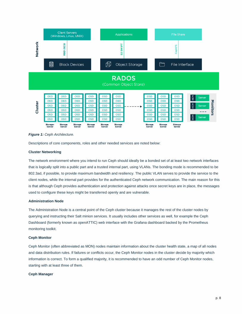
Figure 1: Ceph Architecture.
Descriptions of core components, roles and other needed services are noted below:
Cluster Networking
The network environment where you intend to run Ceph should ideally be a bonded set of at least two network interfaces
that is logically split into a public part and a trusted internal part, using VLANs. The bonding mode is recommended to be
802.3ad, if possible, to provide maximum bandwidth and resiliency. The public VLAN serves to provide the service to the
client nodes, while the internal part provides for the authenticated Ceph network communication. The main reason for this
is that although Ceph provides authentication and protection against attacks once secret keys are in place, the messages
used to configure these keys might be transferred openly and are vulnerable.
Administration Node
The Administration Node is a central point of the Ceph cluster because it manages the rest of the cluster nodes by
querying and instructing their Salt minion services. It usually includes other services as well, for example the Ceph
Dashboard (formerly known as openATTIC) web interface with the Grafana dashboard backed by the Prometheus
monitoring toolkit.
Ceph Monitor
Ceph Monitor (often abbreviated as MON) nodes maintain information about the cluster health state, a map of all nodes
and data distribution rules. If failures or conflicts occur, the Ceph Monitor nodes in the cluster decide by majority which
information is correct. To form a qualified majority, it is recommended to have an odd number of Ceph Monitor nodes,
starting with at least three of them.
Ceph Manager
p. 9
The Ceph manager (MGR) collects the state information from the whole cluster. The Ceph manager daemon runs
alongside the monitor daemons. It provides additional monitoring and interfaces the external monitoring and management
systems. The Ceph manager requires no additional configuration, beyond ensuring that it is running.
Ceph OSD
A Ceph OSD is a daemon that handles Object Storage Devices, which are physical or logical storage units (hard disks or
partitions). Object Storage Devices can be physical disks/partitions or logical volumes. The daemon also takes care of
data replication and rebalancing, in case of added or removed nodes. Ceph OSD daemons communicate with monitor
daemons and provide them with the state of the other OSD daemons.
Optional Roles
• Metadata Server
o The metadata servers (MDS) store metadata for the CephFS. By using an MDS, you can execute basic
file system commands such as ls, without overloading the cluster.
• Object Gateway
o The Ceph Object Gateway provided by Object Gateway is an HTTP REST gateway for the RADOS
object store. It is compatible with OpenStack Swift and Amazon S3 and has its own user management.
• NFS Ganesha
o NFS Ganesha provides NFS access to either the Object Gateway or the CephFS. It runs in the user
instead of the kernel space and directly interacts with the Object Gateway or CephFS.
• iSCSI Gateway
o iSCSI is a storage network protocol that allows clients to send SCSI commands to SCSI storage
devices (targets) on remote servers.
Additional Network Infrastructure Components / Services
• Domain Name Service (DNS): An external, network-accessible service to map IP Addresses to hostnames for all
cluster resource nodes.
• Network Time Protocol (NTP): An external, network-accessible service to obtain and synchronize system times
to aid in timestamp consistency. It is recommended that you to point all resource nodes as a physical
system/device that provides this service.
• Software Update Service: Access to a network-based repository for software update packages. This can be
accessed directly from each node via registration to the SUSE Customer Center (SCC) or from local servers
running a SUSE Subscription Management Tool (SMT) instance. As each node is deployed, it can be pointed to
the respective update service; then update notification and applications will be managed by the configuration
management web interface.
p. 10
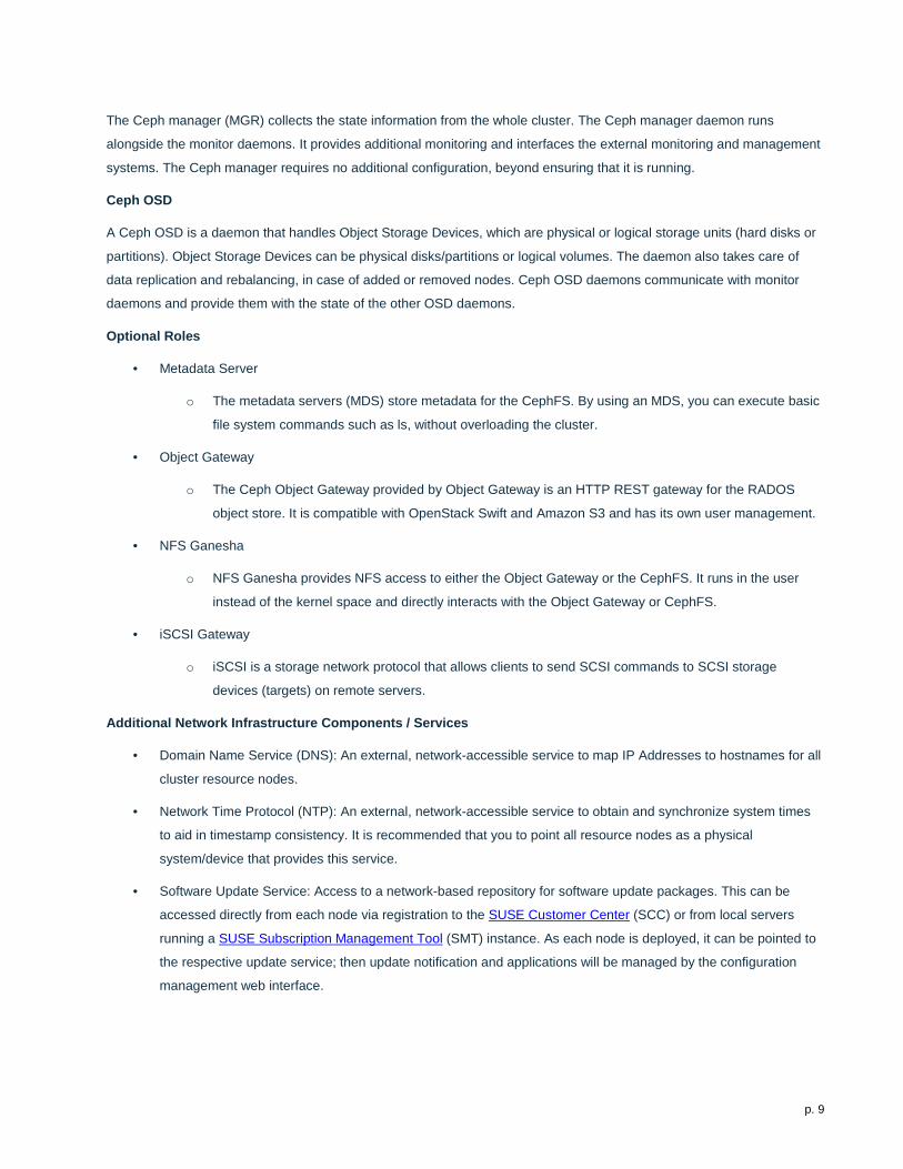
5. Solution Details This document focuses on a new, basic SUSE Enterprise Storage deployment on the HPE Synergy platform, which could
be scaled over time. More physical nodes could also be added, to augment the cluster’s functionality and capacity or to
replace some of the initial resource nodes. To provide a production-ready cluster and to take advantage of the HPE
Synergy platform and its composable features, the following figure shows the target logical cluster deployment.
Figure 2: Deployment Logical View.
5.1 Deployment Flow This section is meant as a companion guide to the official network, system and software product deployment
documentation, citing specific settings as needed for this reference implementation. Default settings are assumed to be in
use, unless otherwise cited, to accomplish the respective best practices and design decisions herein.
Given the very detailed information contained in the SUSE Enterprise Storage Deployment Guide, only the following
additional, incremental configurations and modifications are described below.
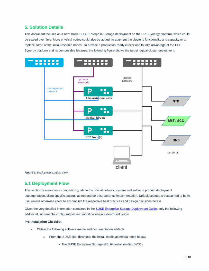
Pre-Installation Checklist
• Obtain the following software media and documentation artifacts:
o From the SUSE site, download the install media as media noted below:
The SUSE Enterprise Storage x86_64 install media (DVD1)
p. 11
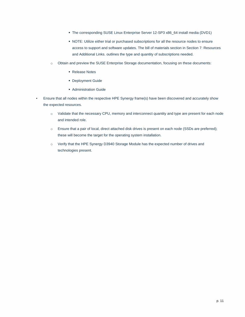
The corresponding SUSE Linux Enterprise Server 12-SP3 x86_64 install media (DVD1)
NOTE: Utilize either trial or purchased subscriptions for all the resource nodes to ensure
access to support and software updates. The bill of materials section in Section 7: Resources
and Additional Links. outlines the type and quantity of subscriptions needed.
o Obtain and preview the SUSE Enterprise Storage documentation, focusing on these documents:
Release Notes
Deployment Guide
Administration Guide
• Ensure that all nodes within the respective HPE Synergy frame(s) have been discovered and accurately show
the expected resources.
o Validate that the necessary CPU, memory and interconnect quantity and type are present for each node
and intended role.
o Ensure that a pair of local, direct attached disk drives is present on each node (SSDs are preferred);
these will become the target for the operating system installation.
o Verify that the HPE Synergy D3940 Storage Module has the expected number of drives and
technologies present.
p. 12
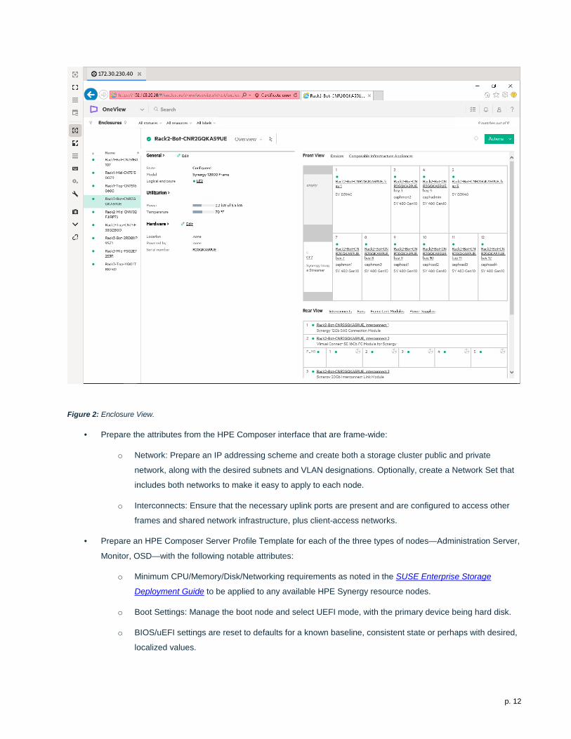
Figure 2: Enclosure View.
• Prepare the attributes from the HPE Composer interface that are frame-wide:
o Network: Prepare an IP addressing scheme and create both a storage cluster public and private
network, along with the desired subnets and VLAN designations. Optionally, create a Network Set that
includes both networks to make it easy to apply to each node.
o Interconnects: Ensure that the necessary uplink ports are present and are configured to access other
frames and shared network infrastructure, plus client-access networks.
• Prepare an HPE Composer Server Profile Template for each of the three types of nodes—Administration Server,
Monitor, OSD—with the following notable attributes:
o Minimum CPU/Memory/Disk/Networking requirements as noted in the SUSE Enterprise Storage
Deployment Guide to be applied to any available HPE Synergy resource nodes.
o Boot Settings: Manage the boot node and select UEFI mode, with the primary device being hard disk.
o BIOS/uEFI settings are reset to defaults for a known baseline, consistent state or perhaps with desired,
localized values.
p. 13
Use consistent and up-to-date versions for BIOS/uEFI/device firmware to reduce potential
troubleshooting issues later.
o Connections: Associate both the public and private networks, or the designated Network Set to the
higher numbered Mezzanine Ports (leaving the “a” port unassociated for possible future usages).
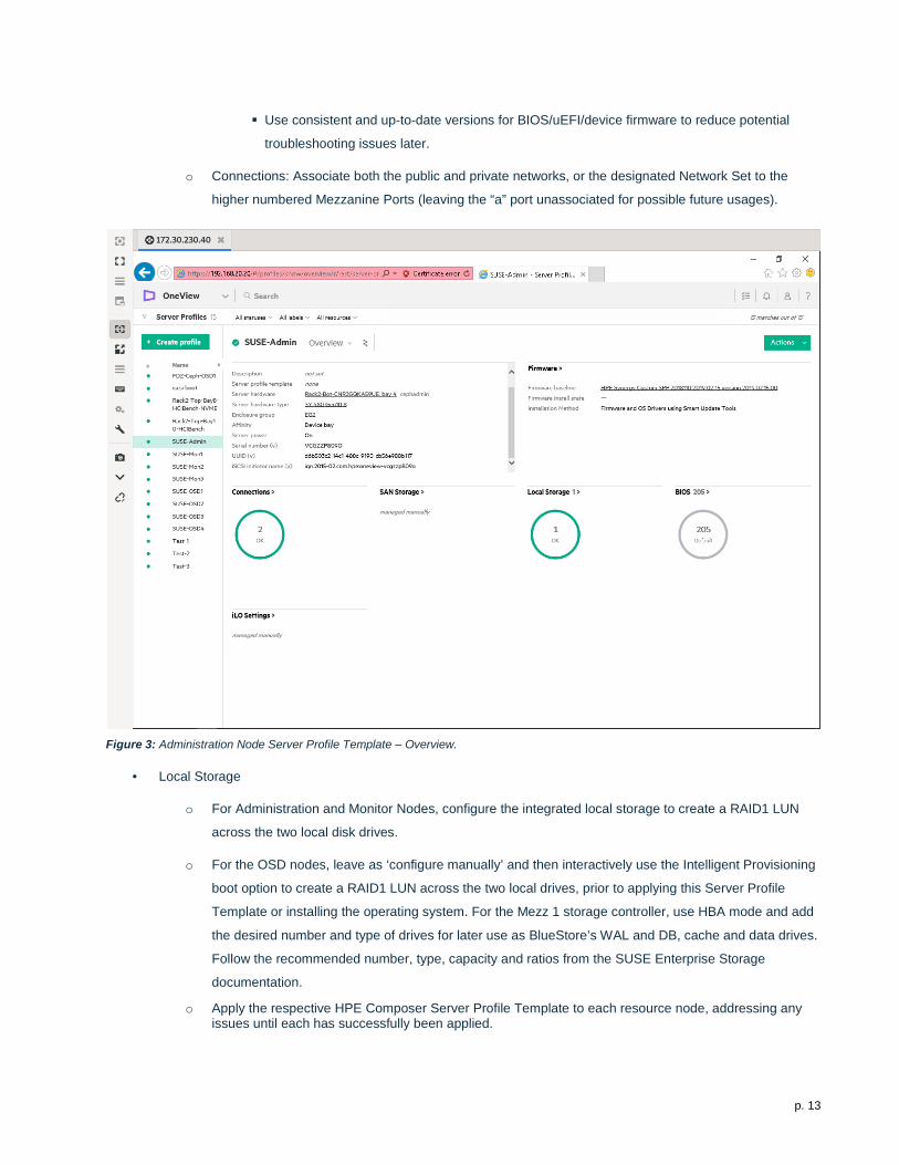
Figure 3: Administration Node Server Profile Template – Overview.
• Local Storage
o For Administration and Monitor Nodes, configure the integrated local storage to create a RAID1 LUN
across the two local disk drives.
o For the OSD nodes, leave as ‘configure manually’ and then interactively use the Intelligent Provisioning
boot option to create a RAID1 LUN across the two local drives, prior to applying this Server Profile
Template or installing the operating system. For the Mezz 1 storage controller, use HBA mode and add
the desired number and type of drives for later use as BlueStore’s WAL and DB, cache and data drives.
Follow the recommended number, type, capacity and ratios from the SUSE Enterprise Storage
documentation.
o Apply the respective HPE Composer Server Profile Template to each resource node, addressing any issues until each has successfully been applied.
p. 14
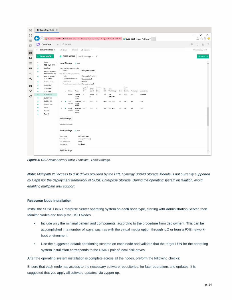
Figure 4: OSD Node Server Profile Template - Local Storage.
Note: Multipath I/O access to disk drives provided by the HPE Synergy D3940 Storage Module is not currently supported
by Ceph nor the deployment framework of SUSE Enterprise Storage. During the operating system installation, avoid
enabling multipath disk support.
Resource Node Installation
Install the SUSE Linux Enterprise Server operating system on each node type, starting with Administration Server, then
Monitor Nodes and finally the OSD Nodes.
• Include only the minimal pattern and components, according to the procedure from deployment. This can be
accomplished in a number of ways, such as with the virtual media option through iLO or from a PXE network-
boot environment.
• Use the suggested default partitioning scheme on each node and validate that the target LUN for the operating
system installation corresponds to the RAID1 pair of local disk drives.
After the operating system installation is complete across all the nodes, preform the following checks:
Ensure that each node has access to the necessary software repositories, for later operations and updates. It is
suggested that you apply all software updates, via zypper up.
p. 15
NTP is configured and operational, synchronizing with a source outside the cluster via ntpq –pn.
* DNS is configured and operational, referencing a source outside the cluster.
If necessary, adjust the udev rules to ensure that network interfaces are identified (as needed) in the same logical order
across the systems, to make later steps easier. Ensure that the respective network interfaces are bonded together with
the associated VLANs configured. While configuring these interfaces, it is also recommended to disable IPv6 functionality
and the firewall on each node.
Note: For environments that require firewalls to be in place, refer to the "Cluster Deployment" portion in the SUSE
Enterprise Storage Deployment Guide.
Cluster Deployment
Follow the process steps noted in the "Cluster Deployment" portion of the SUSE Enterprise Storage Deployment Guide.
You are strongly encouraged to utilize the "DeepSea" approach, which saves the administrator time and helps to
confidently perform complex operations on a Ceph cluster in a staged fashion:
• Complete Stage 0 (preparation) and Stage 1 (discovery).
• Before executing Stage 2:
o You might want to take advantage of SSD devices for BlueStore WAL/DB (if available), to help improve
the overall performance of your cluster. This can be accomplished from the command line on the
Administration Node via:
# salt-run proposal.populate \ name=synergy ratio=6 target='cephosd*' format=bluestore \ wal-size=2g db-size=50g db=745 wal=745 ssd=spinner=True data=279
Note: The size values might need adjustment to effectively use the drive capacity and quantity in your configuration.
• Create a policy.cfg file that references the above generated /srv/pillar/ceph/proposals/profile-synergy contents.
• At this point, you should also review and validate the /srv/pillar/ceph/proposals/profile-
synergy/stack/default/ceph/minions/*.yml content for the OSD nodes, to ensure that the correct disk designations
are in place.
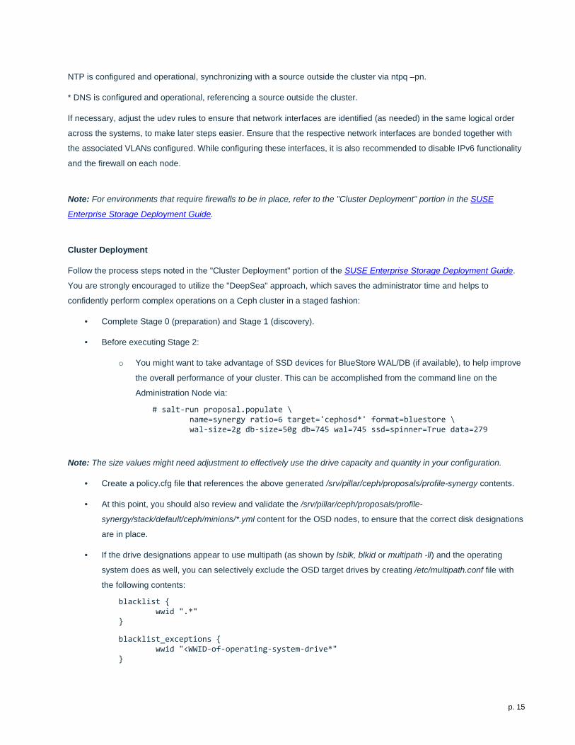
• If the drive designations appear to use multipath (as shown by lsblk, blkid or multipath -ll) and the operating
system does as well, you can selectively exclude the OSD target drives by creating /etc/multipath.conf file with
the following contents:
blacklist { wwid ".*" } blacklist_exceptions { wwid "<WWID-of-operating-system-drive*" }
p. 16
• Execute systemctl reload multipathd, re-run the previous proposal.populate or manually modify the OSD node
minion files to reflect the drive designation of one I/O path or the other.
• Then execute Stage 2 (configuration), Stage 3 (deployment) and Stage 4 (services) to complete the deployment.
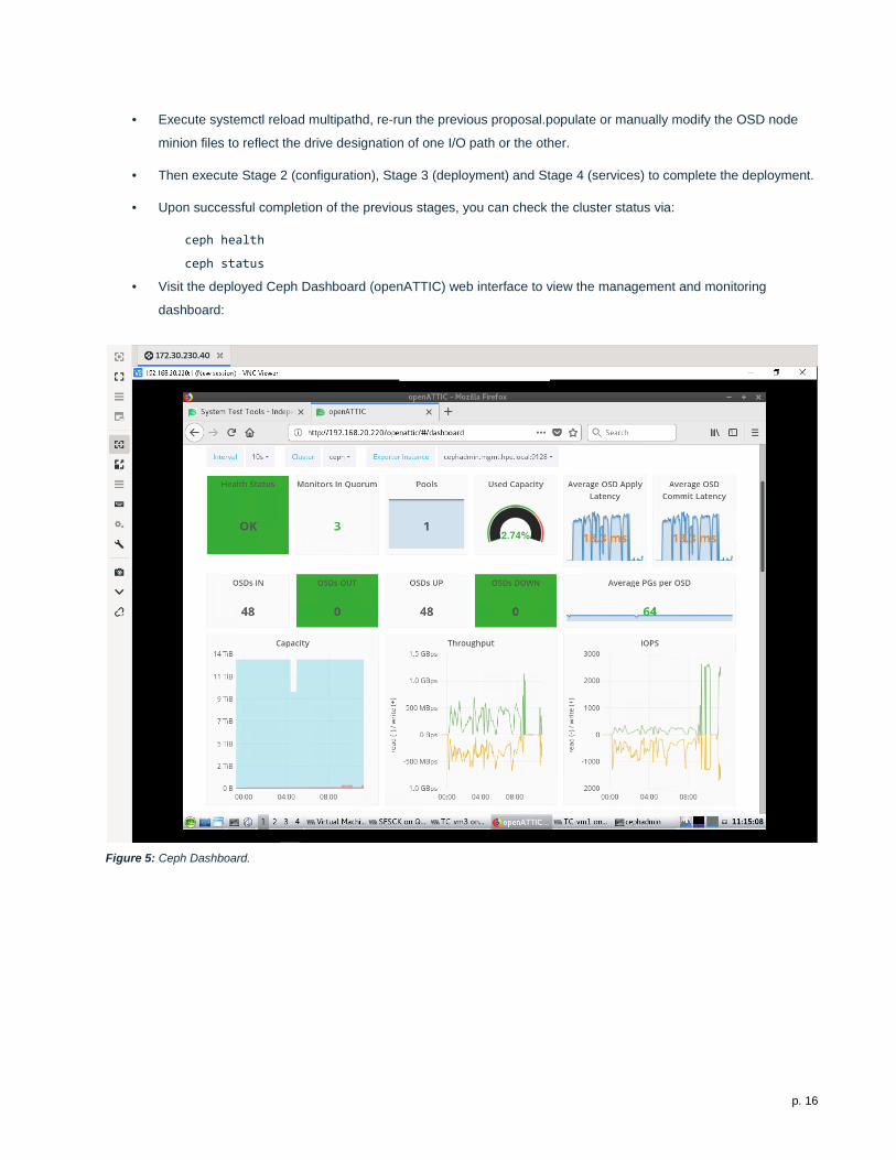
• Upon successful completion of the previous stages, you can check the cluster status via:
ceph health
ceph status
• Visit the deployed Ceph Dashboard (openATTIC) web interface to view the management and monitoring
dashboard:
Figure 5: Ceph Dashboard.
p. 17
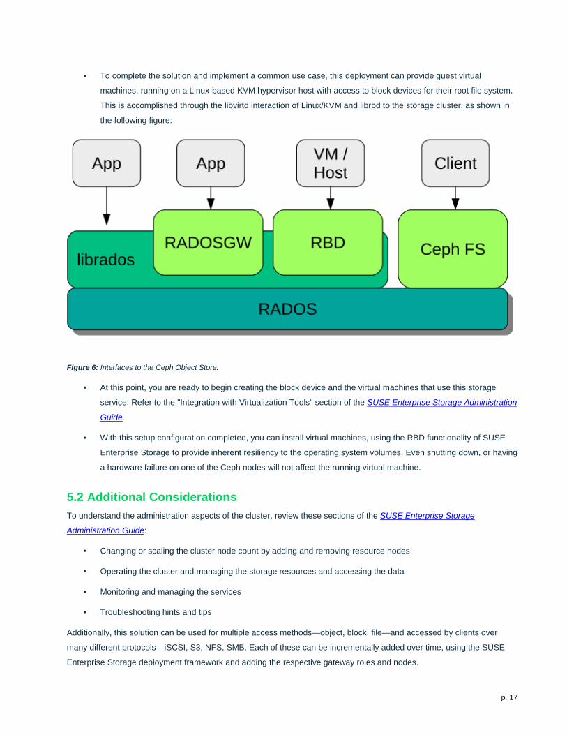
• To complete the solution and implement a common use case, this deployment can provide guest virtual
machines, running on a Linux-based KVM hypervisor host with access to block devices for their root file system.
This is accomplished through the libvirtd interaction of Linux/KVM and librbd to the storage cluster, as shown in
the following figure:
Figure 6: Interfaces to the Ceph Object Store.
• At this point, you are ready to begin creating the block device and the virtual machines that use this storage
service. Refer to the "Integration with Virtualization Tools" section of the SUSE Enterprise Storage Administration
Guide.
• With this setup configuration completed, you can install virtual machines, using the RBD functionality of SUSE
Enterprise Storage to provide inherent resiliency to the operating system volumes. Even shutting down, or having
a hardware failure on one of the Ceph nodes will not affect the running virtual machine.
5.2 Additional Considerations To understand the administration aspects of the cluster, review these sections of the SUSE Enterprise Storage
Administration Guide:
• Changing or scaling the cluster node count by adding and removing resource nodes
• Operating the cluster and managing the storage resources and accessing the data
• Monitoring and managing the services
• Troubleshooting hints and tips
Additionally, this solution can be used for multiple access methods—object, block, file—and accessed by clients over
many different protocols—iSCSI, S3, NFS, SMB. Each of these can be incrementally added over time, using the SUSE
Enterprise Storage deployment framework and adding the respective gateway roles and nodes.
p. 18
6. Conclusion After understanding and working through the steps described in this document, you should have a working software-
defined storage platform that is scalable through the addition of even more resource nodes, as needed. SUSE Enterprise
Storage provides a complete suite of the necessary software and processes and leverages the composability aspect of
HPE Synergy to create a production-worthy and agile platform.
7. Resources and Additional Links HPE Synergy
• HPE Synergy 480 Gen10 System
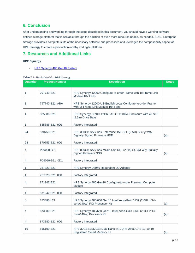
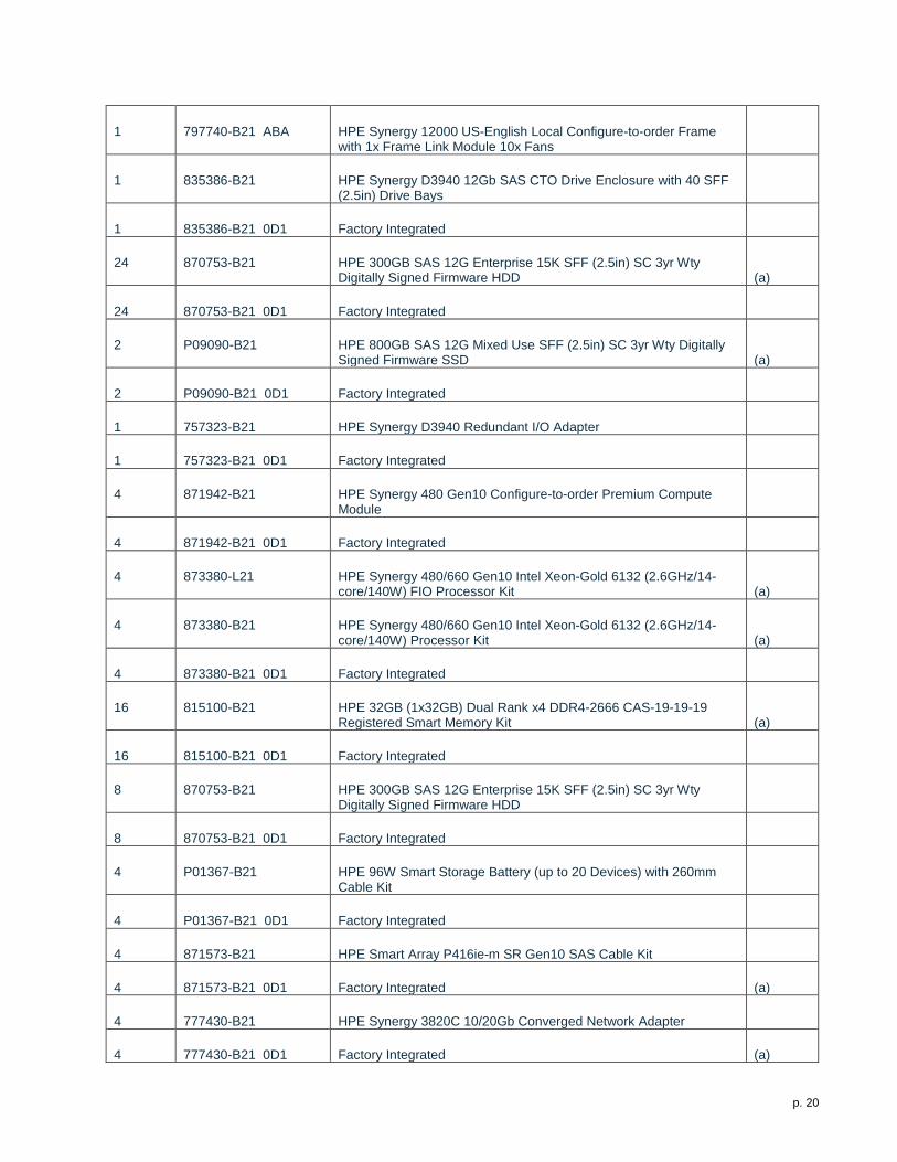
Table 7.1: Bill of Materials - HPE Synergy
Quantity Product Number Description Notes
1 797740-B21 HPE Synergy 12000 Configure-to-order Frame with 1x Frame Link Module 10x Fans
1 797740-B21 ABA HPE Synergy 12000 US-English Local Configure-to-order Frame with 1x Frame Link Module 10x Fans
1 835386-B21 HPE Synergy D3940 12Gb SAS CTO Drive Enclosure with 40 SFF (2.5in) Drive Bays
1 835386-B21 0D1 Factory Integrated
24 870753-B21 HPE 300GB SAS 12G Enterprise 15K SFF (2.5in) SC 3yr Wty Digitally Signed Firmware HDD (a)
24 870753-B21 0D1 Factory Integrated
4 P09090-B21 HPE 800GB SAS 12G Mixed Use SFF (2.5in) SC 3yr Wty Digitally Signed Firmware SSD (a)
4 P09090-B21 0D1 Factory Integrated
1 757323-B21 HPE Synergy D3940 Redundant I/O Adapter
1 757323-B21 0D1 Factory Integrated
4 871942-B21 HPE Synergy 480 Gen10 Configure-to-order Premium Compute Module
4 871942-B21 0D1 Factory Integrated
4 873380-L21 HPE Synergy 480/660 Gen10 Intel Xeon-Gold 6132 (2.6GHz/14-core/140W) FIO Processor Kit (a)
4 873380-B21 HPE Synergy 480/660 Gen10 Intel Xeon-Gold 6132 (2.6GHz/14-core/140W) Processor Kit (a)
4 873380-B21 0D1 Factory Integrated
16 815100-B21 HPE 32GB (1x32GB) Dual Rank x4 DDR4-2666 CAS-19-19-19 Registered Smart Memory Kit (a)
p. 19
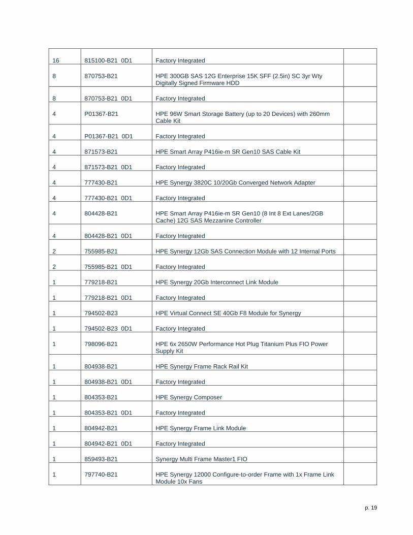
16 815100-B21 0D1 Factory Integrated
8 870753-B21 HPE 300GB SAS 12G Enterprise 15K SFF (2.5in) SC 3yr Wty Digitally Signed Firmware HDD
8 870753-B21 0D1 Factory Integrated
4 P01367-B21 HPE 96W Smart Storage Battery (up to 20 Devices) with 260mm Cable Kit
4 P01367-B21 0D1 Factory Integrated
4 871573-B21 HPE Smart Array P416ie-m SR Gen10 SAS Cable Kit
4 871573-B21 0D1 Factory Integrated
4 777430-B21 HPE Synergy 3820C 10/20Gb Converged Network Adapter
4 777430-B21 0D1 Factory Integrated
4 804428-B21 HPE Smart Array P416ie-m SR Gen10 (8 Int 8 Ext Lanes/2GB Cache) 12G SAS Mezzanine Controller
4 804428-B21 0D1 Factory Integrated
2 755985-B21 HPE Synergy 12Gb SAS Connection Module with 12 Internal Ports
2 755985-B21 0D1 Factory Integrated
1 779218-B21 HPE Synergy 20Gb Interconnect Link Module
1 779218-B21 0D1 Factory Integrated
1 794502-B23 HPE Virtual Connect SE 40Gb F8 Module for Synergy
1 794502-B23 0D1 Factory Integrated
1 798096-B21 HPE 6x 2650W Performance Hot Plug Titanium Plus FIO Power Supply Kit
1 804938-B21 HPE Synergy Frame Rack Rail Kit
1 804938-B21 0D1 Factory Integrated
1 804353-B21 HPE Synergy Composer
1 804353-B21 0D1 Factory Integrated
1 804942-B21 HPE Synergy Frame Link Module
1 804942-B21 0D1 Factory Integrated
1 859493-B21 Synergy Multi Frame Master1 FIO
1 797740-B21 HPE Synergy 12000 Configure-to-order Frame with 1x Frame Link Module 10x Fans
p. 20
1 797740-B21 ABA HPE Synergy 12000 US-English Local Configure-to-order Frame with 1x Frame Link Module 10x Fans
1 835386-B21 HPE Synergy D3940 12Gb SAS CTO Drive Enclosure with 40 SFF (2.5in) Drive Bays
1 835386-B21 0D1 Factory Integrated
24 870753-B21 HPE 300GB SAS 12G Enterprise 15K SFF (2.5in) SC 3yr Wty Digitally Signed Firmware HDD (a)
24 870753-B21 0D1 Factory Integrated
2 P09090-B21 HPE 800GB SAS 12G Mixed Use SFF (2.5in) SC 3yr Wty Digitally Signed Firmware SSD (a)
2 P09090-B21 0D1 Factory Integrated
1 757323-B21 HPE Synergy D3940 Redundant I/O Adapter
1 757323-B21 0D1 Factory Integrated
4 871942-B21 HPE Synergy 480 Gen10 Configure-to-order Premium Compute Module
4 871942-B21 0D1 Factory Integrated
4 873380-L21 HPE Synergy 480/660 Gen10 Intel Xeon-Gold 6132 (2.6GHz/14-core/140W) FIO Processor Kit (a)
4 873380-B21 HPE Synergy 480/660 Gen10 Intel Xeon-Gold 6132 (2.6GHz/14-core/140W) Processor Kit (a)
4 873380-B21 0D1 Factory Integrated
16 815100-B21 HPE 32GB (1x32GB) Dual Rank x4 DDR4-2666 CAS-19-19-19 Registered Smart Memory Kit (a)
16 815100-B21 0D1 Factory Integrated
8 870753-B21 HPE 300GB SAS 12G Enterprise 15K SFF (2.5in) SC 3yr Wty Digitally Signed Firmware HDD
8 870753-B21 0D1 Factory Integrated
4 P01367-B21 HPE 96W Smart Storage Battery (up to 20 Devices) with 260mm Cable Kit
4 P01367-B21 0D1 Factory Integrated
4 871573-B21 HPE Smart Array P416ie-m SR Gen10 SAS Cable Kit
4 871573-B21 0D1 Factory Integrated (a)
4 777430-B21 HPE Synergy 3820C 10/20Gb Converged Network Adapter
4 777430-B21 0D1 Factory Integrated (a)
p. 21
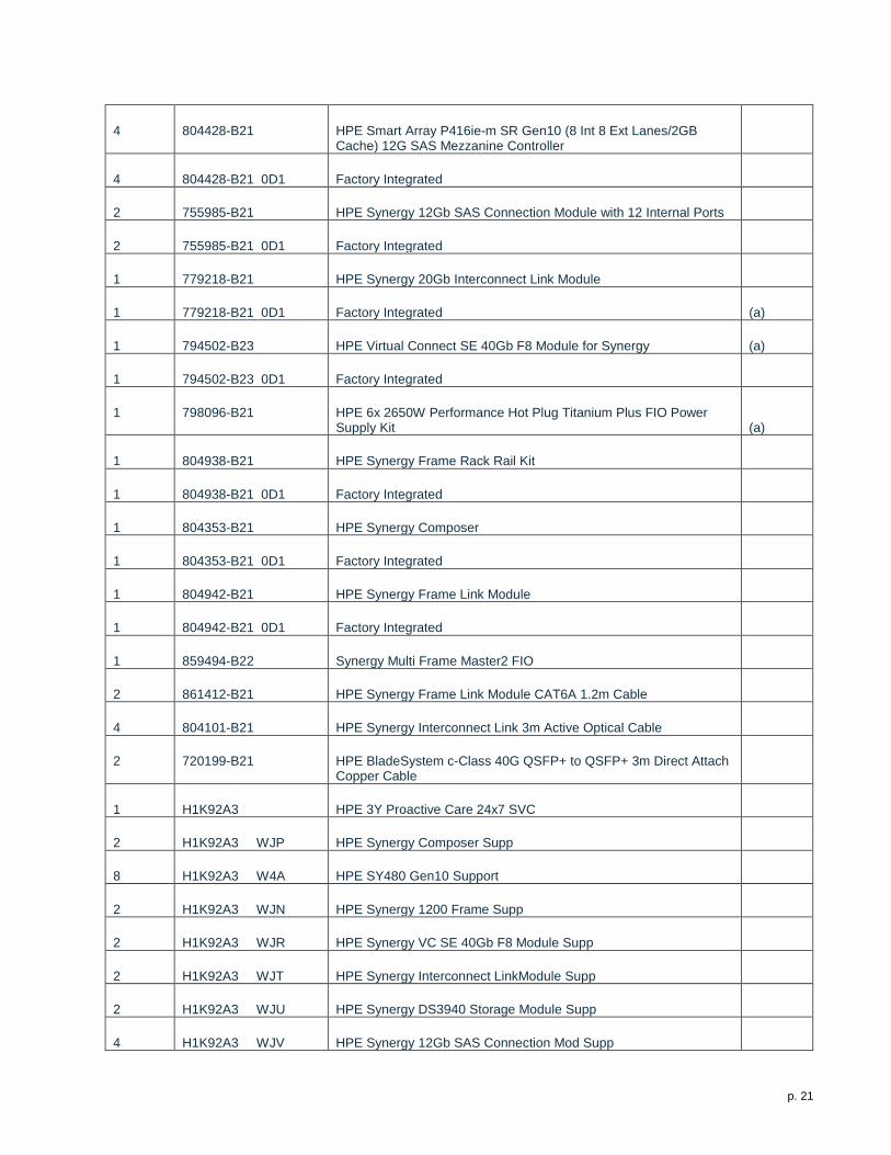
4 804428-B21 HPE Smart Array P416ie-m SR Gen10 (8 Int 8 Ext Lanes/2GB Cache) 12G SAS Mezzanine Controller
4 804428-B21 0D1 Factory Integrated
2 755985-B21 HPE Synergy 12Gb SAS Connection Module with 12 Internal Ports
2 755985-B21 0D1 Factory Integrated
1 779218-B21 HPE Synergy 20Gb Interconnect Link Module
1 779218-B21 0D1 Factory Integrated (a)
1 794502-B23 HPE Virtual Connect SE 40Gb F8 Module for Synergy (a)
1 794502-B23 0D1 Factory Integrated
1 798096-B21 HPE 6x 2650W Performance Hot Plug Titanium Plus FIO Power Supply Kit (a)
1 804938-B21 HPE Synergy Frame Rack Rail Kit
1 804938-B21 0D1 Factory Integrated
1 804353-B21 HPE Synergy Composer
1 804353-B21 0D1 Factory Integrated
1 804942-B21 HPE Synergy Frame Link Module
1 804942-B21 0D1 Factory Integrated
1 859494-B22 Synergy Multi Frame Master2 FIO
2 861412-B21 HPE Synergy Frame Link Module CAT6A 1.2m Cable
4 804101-B21 HPE Synergy Interconnect Link 3m Active Optical Cable
2 720199-B21 HPE BladeSystem c-Class 40G QSFP+ to QSFP+ 3m Direct Attach Copper Cable
1 H1K92A3 HPE 3Y Proactive Care 24x7 SVC
2 H1K92A3 WJP HPE Synergy Composer Supp
8 H1K92A3 W4A HPE SY480 Gen10 Support
2 H1K92A3 WJN HPE Synergy 1200 Frame Supp
2 H1K92A3 WJR HPE Synergy VC SE 40Gb F8 Module Supp
2 H1K92A3 WJT HPE Synergy Interconnect LinkModule Supp
2 H1K92A3 WJU HPE Synergy DS3940 Storage Module Supp
4 H1K92A3 WJV HPE Synergy 12Gb SAS Connection Mod Supp
p. 22
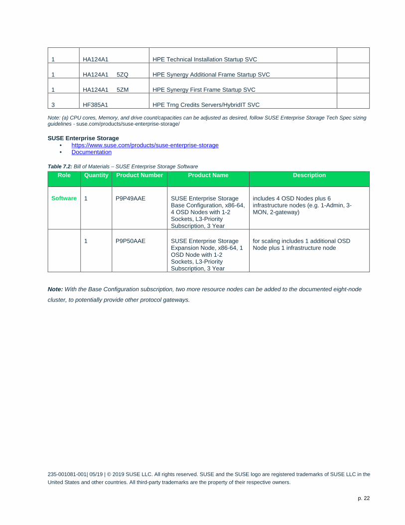
1 HA124A1 HPE Technical Installation Startup SVC
1 HA124A1 5ZQ HPE Synergy Additional Frame Startup SVC
1 HA124A1 5ZM HPE Synergy First Frame Startup SVC
3 HF385A1 HPE Trng Credits Servers/HybridIT SVC Note: (a) CPU cores, Memory, and drive count/capacities can be adjusted as desired, follow SUSE Enterprise Storage Tech Spec sizing guidelines - suse.com/products/suse-enterprise-storage/
SUSE Enterprise Storage • https://www.suse.com/products/suse-enterprise-storage • Documentation
Table 7.2: Bill of Materials – SUSE Enterprise Storage Software Role Quantity Product Number Product Name Description
Software 1 P9P49AAE SUSE Enterprise Storage Base Configuration, x86-64, 4 OSD Nodes with 1-2 Sockets, L3-Priority Subscription, 3 Year
includes 4 OSD Nodes plus 6 infrastructure nodes (e.g. 1-Admin, 3-MON, 2-gateway)
1 P9P50AAE SUSE Enterprise Storage Expansion Node, x86-64, 1 OSD Node with 1-2 Sockets, L3-Priority Subscription, 3 Year
for scaling includes 1 additional OSD Node plus 1 infrastructure node
Note: With the Base Configuration subscription, two more resource nodes can be added to the documented eight-node
cluster, to potentially provide other protocol gateways.
235-001081-001| 05/19 | © 2019 SUSE LLC. All rights reserved. SUSE and the SUSE logo are registered trademarks of SUSE LLC in the United States and other countries. All third-party trademarks are the property of their respective owners.