Embed Size (px)
Citation preview

SURVIVAL GUIDE FOR THE GEODESY LAB
Gina Schmalzle

INDEX
CHAPTER 1: SETTING UP A GPS STATION1. ANTENNA SETUP 3
i. Setup with a spike mount 4ii. Setup with a tripod 5
2. ATTACHING THE GPS ANTENNA 73A. 4000ssi RECEIVER SETUP (UNAVCO DIRECTIONS) 93B. 4000ssi RECEIVER SETUP (PETE’S DIRECTIONS) 114. TROUBLESHOOTING PROBLEMS WITH THE FEILD EQUIPMENT 12
CHAPTER 2: USING GIPSY/OASIS CAN BE FUN!
PROCESSING YOUR DATA1. LOCATION OF THE PROCESSING SCRIPTS 142. STATION NAMES 143. DESCRIPTION OF TRIMBLE DATA FILES 144. DESCRIPTION OF RINEX FILES 155. TEQC 156. GENERATING THE STA_INFO FILES 17
i sta_id 18ii sta_pos 18iii sta_svec 19
7. MAKING YOUR *.stacov AND *.gd FILES 208. MERGING YOUR DATA 229. CALCULATING ERROR 22
CREATING A VELOCITY PROFILE FROM PROCESSED DATA10. CREATING A sites.gd FILE 2311. CREATING A noam.st FILE 2312. CREATING A noam.dat FILE 2413. CREATING A noam.res FILE 2414. CREATING YOUR VELOCITY MAP 24
Survival Guide, 20 JAN 04 Gina Schmalzle

CHAPTER 1: SETTING UP A GPS STATIONA ground GPS station consists of several different components: the mount, the antenna, the receiver, the connectors, and the power supply. In this chapter, we will discuss how to setup and use these parts.
In order to get statistically good data, the system need to run for at least three day, and one UTC day should not have less than 8 hours of data. Be sure to arrange for the instruments to be run for at least this amount of time.
There are many different ways to set up a GPS station because it would be way too simple to just have one standard way. This manual will explain several ways to set up an antenna.
1. ANTENNA SETUP
Picture of a Trimble L1/L2 Choke ring antenna:
Survival Guide, 20 JAN 04 Gina Schmalzle
i. Setup with a spike mount
The picture above shows an assembled spike mount. There is one more leg that should may be attached for better stability, but for alignment purposes, only two legs and the center spike should be touching the ground. The 3rd leg is lowered after the alignment.
At the bottom of the thickest leg there is a plumb bob. The plumb bob is screwed into the leg.
If you are using the Zephyr Geodetic Antenna, you will need to use a leveling plate. The leveling plate has a machined flat side marked ‘FLAT’. If you do not see “FLAT’ written on the leveling plate, the level side is the one with circular marks in it. Slide the leveling plate so that it is about half way up the center spike mount. Make sure the plate points out to an area where you would be able to place your level (i.e., no legs are blocking the plate).
Two of the smaller legs should be set perpendicular to each other. These two legs are used to adjust the leveling of the antenna (discussed later).
1. Screw the antenna onto the top of the spike mount. 2. Move the assembly so that the tip of the plumb bob is in the hole of the pin in the center of the monument. 3. Adjust the legs so that the assembly may move freely about the pin. 4. Rotate the assembly until the cable port on the antenna is facing true north.
Survival Guide, 20 JAN 04 Gina Schmalzle

5. Lower the two adjustable legs. Keep the third thin leg (not shown in the picture above) up. Make sure that the base of the legs are secure into the ground so that there will be no possible movement by settling of the soil. Use rocks as your base if you have to. 6. Plug in antenna cable. 7. Place a level perpendicular to one of the adjusting legs and adjust the other leg height until the antenna is level in that direction. (If you are using a Zephyr Geodetic antenna, use the leveling plate and place the level parallel to the direction of a leg, if you are using the choke ring antenna, place the level on the top of the antenna). Turn the level 90 degrees so that it is parallel to the other leg and repeat. Continue to do so until the antenna is perfectly level in both directions. For the choke ring antennas: Try placing the level on top of the antenna but in between the two leveling legs. For the leveling plate: try rotating the level 45 degrees so that the level is parallel to neither of the legs. If the antenna is still level, tighten the adjustable legs and lower and tighten the third. Check again the leveling. Be aware that the leveling is very tricky. I have found that when you tighten the legs you may also throw off the leveling. Observe this phenomenon and try to compensate for it. 8. Double check that the direction of the cable port is still correct9. Double check that the plumb bob is still in the monument pin. 10. Double check the leveling.11. Plug the other end of the antenna cable into the receiver.
Continue to Receiver Setup.
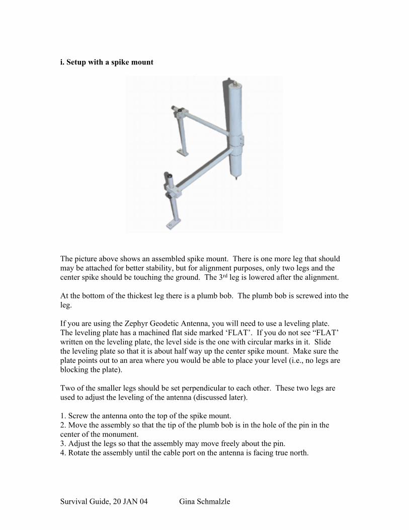
ii. Setup with a tripod The information for the setup with a tripod was obtained through UNAVCO (http://www.unavco.ucar.edu/project_support/campaign/documentation/tripod.pdf).
Survival Guide, 20 JAN 04 Gina Schmalzle
Steps 1-9 are for both rotating and non-rotating tribrachs: 1.Extend tripod legs so the top of the tripod head comes up to your chin. Lock legs at this height with the leg screws. If the ground is not level the legs will have to be extended at different lengths.
2.Attach tribrach to tripod head using the large center screw on the tripod head. Make sure that the leveling foot screws on the tribrach are centered half way between their range of movement.
3. Open tripod legs over the mark and step (set) one leg into the ground at about a 45o slant angle and about 3 feet from the station mark. Look through the optical plummet and position the cross hairs over the point using the remaining two tripod legs. If viewing or crosshairs are out of focus adjust the crosshairs ring first until the crosshairs appear clear and crisp. Adjust the focus ring until the image is in focus. To check for parallax slowly move your head around while looking through the optical plummet. You should see no movement between the crosshairs and the focused background (this is known as being out of parallax), nor should the crosshairs move apart.
4. Once the cross hairs are within 1 cm of the point and the head of the tripod is visually level, step the remaining two legs into the ground. At this point sand bag or tie down the tripod legs.
5. Precisely position the tribrach crosshairs over the point using the leveling foot screws on the tribrach.
6. Level the bull’s-eye bubble on the tribrach by using two tripod legs. (Do not level using the tribrach foot screws.) At this point you are leveling the tripod head.
8. Once the bull’s-eye bubble is precisely level, look through the optical plummet to ensure that the crosshairs are over the point or at least within a few cms. Center the crosshairs precisely over the point by loosening the tripod head screw and gently slide the tribrach and adapter over the point. When centered, tighten the tripod head screw. If tribrach overhangs tripod head, return to step 2.
9. Check the level bubble. If the level is out: just a little - return to step 7.
Survival Guide, 20 JAN 04 Gina Schmalzle
by a lot - (more than a couple of mms) - return to step 5. UNAVCO 8/02 For Tribrachs with Non-Rotating Optical Plummets: 10.Check the set up and calibration of the tribrach by attaching the plumb bob to the tripod head screw so it hangs over the point. It should hang precisely over the point +/- the plumb bob string width.
NOTE: This will not necessarily be true in windy conditions. In windy conditions the plumb bob will be blown away from the mark. If the site is located in an area with high winds the calibration of the tribrach can be checked indoors by performing the set up procedure.
For Tribrach with Rotating Optical Plummet: 10. Follow steps 1-9 above.
11. Turn the optical plummet so that the plate bubble tube is parallel to two footscrews of the tribrach. Center the bubble by adjusting these two footscrews in equal and opposite directions.
12. Turn the optical plummet through 90o. Center the bubble with the third footscrew.
13. Turn the optical plummet through 90o so that the bubble is parallel to the first 2 footscrews. Note position of bubble. If the bubble is centered between the middle divisions, then the tribrach is level in this plane. If the bubble sits more than one division off center, then note how many divisions off center it lies and by adjusting the two footscrews in equal and opposite directions bring the bubble toward the center by half the amount it was off center before. Turn the optical plummet through 180o again and check where the bubble rests. Repeat the process until the bubble is within one division of the central division.
14. Now turn the optical plummet through 90o and check the level in this plane. Note the position of the bubble. If the bubble is off center by more than one division, turn the third footscrew to bring the bubble to a point halfway between the position noted and the centered position. Rotate through 180o and check again using the third footscrew for any fine adjustment.
15. Now rotate the optical plummet through 360o and check if the bubble remains within 1 division of the center for any position.
16. Center the adapter precisely over the point by loosening the tripod head screw and gently sliding the tribrach and adapter over the point. When centered tighten the tripod head screw.
17.Check the set up and calibration of the tribrach by rotating the adapter 180o and check the plummet. If the tribrach is off center by more then 1mm then loosen the tripod head screw and gently slide the tribrach and adapter half the distance it was off. Rotate the adapter 180o and recheck the plumb. The offset should be the same. If not repeat this step again.
2. ATTACHING THE GPS ANTENNA
Survival Guide, 20 JAN 04 Gina Schmalzle

When attaching the antenna to the tribrach first screw the brass adapter plug into the antenna then gently slide the plug into the tribrach adapter or rotating optical plummet.
18. Continue with receiver setup.
Survival Guide, 20 JAN 04 Gina Schmalzle
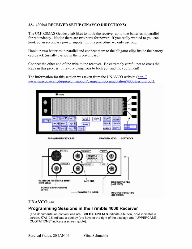
3A. 4000ssi RECEIVER SETUP (UNAVCO DIRECTIONS)
The UM-RSMAS Geodesy lab likes to hook the receiver up to two batteries in parallel for redundancy. Notice there are two ports for power. If you really wanted to you can hook up an secondary power supply. In this procedure we only use one.
Hook up two batteries in parallel and connect them to the alligator clips inside the battery cable sack (usually carried in the receiver case).
Connect the other end of the wire to the receiver. Be extremely careful not to cross the leads in this process. It is very dangerous to both you and the equipment! The information for this section was taken from the UNAVCO website (http://www.unavco.ucar.edu/project_support/campaign/documentation/4000sessions.pdf).
UNAVCO 8/02
Programming Sessions in the Trimble 4000 Receiver (The documentation conventions are: BOLD CAPITALS indicate a button, bold indicates a screen, ITALICS indicate a softkey (the keys to the right of the display), and "UPPERCASE QUOTATIONS" indicate a screen quote).
Survival Guide, 20 JAN 04 Gina Schmalzle
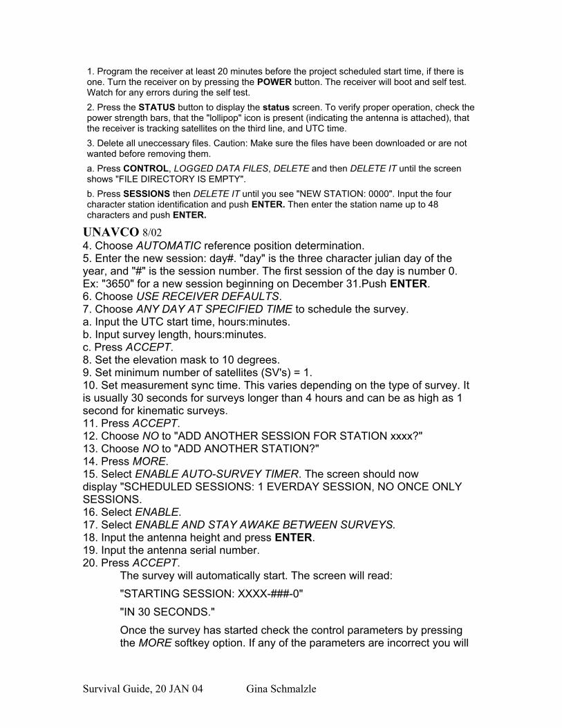
1. Program the receiver at least 20 minutes before the project scheduled start time, if there is one. Turn the receiver on by pressing the POWER button. The receiver will boot and self test. Watch for any errors during the self test. 2. Press the STATUS button to display the status screen. To verify proper operation, check the power strength bars, that the "lollipop" icon is present (indicating the antenna is attached), that the receiver is tracking satellites on the third line, and UTC time. 3. Delete all uneccessary files. Caution: Make sure the files have been downloaded or are not wanted before removing them. a. Press CONTROL, LOGGED DATA FILES, DELETE and then DELETE IT until the screen shows "FILE DIRECTORY IS EMPTY". b. Press SESSIONS then DELETE IT until you see "NEW STATION: 0000". Input the four character station identification and push ENTER. Then enter the station name up to 48 characters and push ENTER.
UNAVCO 8/02 4. Choose AUTOMATIC reference position determination. 5. Enter the new session: day#. "day" is the three character julian day of the year, and "#" is the session number. The first session of the day is number 0. Ex: "3650" for a new session beginning on December 31.Push ENTER. 6. Choose USE RECEIVER DEFAULTS. 7. Choose ANY DAY AT SPECIFIED TIME to schedule the survey. a. Input the UTC start time, hours:minutes. b. Input survey length, hours:minutes. c. Press ACCEPT. 8. Set the elevation mask to 10 degrees. 9. Set minimum number of satellites (SV's) = 1. 10. Set measurement sync time. This varies depending on the type of survey. It is usually 30 seconds for surveys longer than 4 hours and can be as high as 1 second for kinematic surveys. 11. Press ACCEPT. 12. Choose NO to "ADD ANOTHER SESSION FOR STATION xxxx?" 13. Choose NO to "ADD ANOTHER STATION?" 14. Press MORE. 15. Select ENABLE AUTO-SURVEY TIMER. The screen should now display "SCHEDULED SESSIONS: 1 EVERDAY SESSION, NO ONCE ONLY SESSIONS. 16. Select ENABLE. 17. Select ENABLE AND STAY AWAKE BETWEEN SURVEYS. 18. Input the antenna height and press ENTER. 19. Input the antenna serial number. 20. Press ACCEPT.
The survey will automatically start. The screen will read: "STARTING SESSION: XXXX-###-0" "IN 30 SECONDS." Once the survey has started check the control parameters by pressing the MORE softkey option. If any of the parameters are incorrect you will
Survival Guide, 20 JAN 04 Gina Schmalzle

have to stop the current survey and reprogram the receiver from the beginning. 21. Complete the Monument Visit Logsheet. 22. End the survey. A programmed survey will end automatically. When the survey has ended the receiver will automatically start a new survey session. To stop the current survey press the LOG DATA key. Then select END SURVEY. The receiver will prompt "STOP CURRENT SURVEY?". Select YES.
Now you are ready to go! Depending on the station you have just installed you may have to baby-sit it, or you may just be able to leave it. Try to check up on it at least once a day for the next few days.
3B. 4000ssi RECEIVER SETUP (PETE’S DIRECTIONS)NOTICE: DO NOT POWER THE RECEIVER UNTIL THE ANTENNA IS CONNECTED
1.) Set-up antenna on spike mount on top of mark and level the antenna. Make sure there are no obstructions (e.g. tree limbs, concrete posts, etc.) blocking the antenna.
2.) Press the POWER button3.) Press the SESSIONS button – Delete any sessions stored in memory
a. NEW STATION – input 4 character name for station – acceptb. NEW STATION – input site name (usually the nearest town or landmark)
- enterc. Reference Position – automaticd. Input session # = UTC day (Day of year; e.g. January 1 = 001) - entere. Special Controls: Choose Use Receiver Defaultsf. Select schedule: Choose Any day at specified time
i. Start time: 00:00:00ii. Observation time:23:59 – accept
4.) Receiver Defaultsa. Elevation mask = 07º - 15ºb. Minimum SV’s = 4c. Measure Sync. Time = 15.00 – 30.00 seconds
5.) Add Another session – NO6.) Add Another station – NO7.) List – Choose More
a. Choose Enable auto survey timerb. Enablec. Choose Enable stay awake
8.) Input antenna height (0.5 meters) and serial number (last 6 digits found on the preamplifier of the antenna (i.e., where the antenna cable is attached to the antenna). Accept
Survival Guide, 20 JAN 04 Gina Schmalzle

9.) The session will now start in 30 seconds10.) On the log sheet make note of :
a. Starting timeb. Datec. Position. The position may be found by pressing the STATUS button.
Then choose Position from the menu.
4. TROUBLESHOOTING PROBLEMS WITH THE FEILD EQUIPMENT
TRIMBLE 4000SSI RECEIVERS
The Trimble 4000ssi receivers are older and no longer offered through the Trimble website. Problems we have encountered with the aging systems and our solutions to the problems are listed here.
Initializing Problems
The receiver cannot stop initializing. It will not bring you into the main menu and none of the command buttons seem to work. It cannot find any satellites. Why does the receiver hate me?!?!?!
Well, it sounds like some of the Firmware files may be corrupted. Or perhaps the system just got confused. The current (as of 1-20-04) Firmware version we use is 7.19b. So what do you do?
THESE DIRECTIONS ARE ONLY MEANT AS A LAST RESORT. IF YOU CANNOT GET THE SYSTEM WORKING ANY OTHER WAY THEN YOU CAN ATTEMPT THESE DIRECTIONS. GOOD LUCK.
First, you want to try to take as much of your data off the receiver as possible. Use GPload to download your data on your machine.
Then you want to do a hard reset by pressing the LOG DATA and CLEAR buttons while turning on the machine. THIS WILL DELETE ALL THE DATA ON YOUR MACHINE.
Wait about ten minutes to see if the machine will start seeing satellites and acquire its position. If this happens, everything is dandy and you can get on with the rest of the day.
What’s that? It didn’t work? It sounds like you may have some greater problems on your plate. It sounds like your system is beyond being confused—it is corrupted! You may not be able to get your data back if this happens. At this point you will have to download Firmware files on your machine that will replace the corrupted ones. This can be a bit tricky.
Survival Guide, 20 JAN 04 Gina Schmalzle

Download Firmware v.7.19b to your machine by going to the Trimble website at:
http://www.trimble.com/support_trl.asp?Nav=Collection-3849
The upload is the first one listed. Connect the power to the receiver (power 2) and the download cable to IO/Power 1. Double click the update_s.bat and let it run the update. If you are using DOS, go to the directory with the updates and run “UPDATE 1”. You may have to type a different number ie, UPDATE 2 or 3 or 4, in order to run in DOS due to your DOS configuration.
YOU MAY LOOSE ALL OF YOUR DATA FILES ON THE RECEIVER.
Survival Guide, 20 JAN 04 Gina Schmalzle

CHAPTER 2: USING GIPSY/OASIS CAN BE FUN!Written by Gina Schmalzle
Last Updated: August 4, 2005 by Gina Schmalzle and Peter LaFemina
Editors: Batu Osmanoglu and Kim Outerbridge
GIPSY/OASIS (GPS Inferred Positioning SYstem Software) is the software used in the RSMAS Geodesy Lab for processing rinex files produced by GPS (Global Positioning Systems). Rinex is defined as Receiver INdependent EXchange format. It consists of a set of standard definitions and formats that permits interchangeable use of GPS data from dissimilar GPS receiver models or post-processing software. The format includes definitions of time, phase and range. If you are planning on doing any sort of GPS work in this lab, it is absolutely imperative that you know how to process and interpret the data. Try to learn how to use GIPSY as soon as you feel comfortable enough with UNIX.
PROCESSING YOUR DATA
1. LOCATION OF THE PROCESSING SCRIPTS
GPS prcessing scripts are found in/raphael/daily/bin or /giotto/local/bin. GIPSY/OASIS processes ONLY rinex files.
2. STATION NAMES
Station names are four characters long. The name has the flexibility to be lowercase or uppercase, and can also contain numbers. From now on, the sample four character station name used in this manual will be referred to as SITE. Other labels used in this manual are:
JJJ = number of the day of the year, starting from January 1 (001)YY, YYYY = year
MM, MMM = monthDD = day
# = numerical label indicating file number for that day (0, 1, 2...)
3. DESCRIPTION OF TRIMBLE DATA FILES
Trimble data files come in several types. Among those are:
• R-files (of the form *.r00, where the size of the file is approximately 0.5 Mbyte/day)
Survival Guide, 20 JAN 04 Gina Schmalzle

• Data file, downloaded with GPLoad (of the form *.dat, where the approximate size is 1-3Mbytes/day). The Geodesy Lab uses GPLoad to download data from the 4000ssi receivers. GPLoad also provides *.mes, *.ion and *.eph. These files are generally not used/needed during processing unless if you have problems with the XYZ position and/or satellite orbits are off. The *.dat files must be run through TEQC (Translate/Edit/Quality Check, see section 5. TEQC). TEQC converts *.dat files to rinex2 files (rinex2 is the latest version, as of May 7, 2003). For more information on the RINEX v.2 file format, please visit http://www.ngs.noaa.gov/CORS/Rinex2.html.
4. DESCRIPTION OF RINEX FILES
Rinex files are in the form of SITEJJJ#.YYo. Be sure that the o at the end of the name is lowercase.
The first few lines of a rinex files look similar to this:
2 OBSERVATION DATA G (GPS) RINEX VERSION / TYPETRRINEXO V2.5.3 LH IFAG, FFM 14-OCT-96 12:12 PGM / RUN BY / DATERinex conversion COMMENTBIT 2 OF LLI (+4) FLAGS DATA COLLECTED UNDER "AS" CONDITION COMMENTKOSENJAK MARKER NAME0091 MARKER NUMBERMEDVED GURS OBSERVER / AGENCY2322 TRIMBLE 4000SSE 5.68 / 1.26 REC # / TYPE / VERS67153 4000ST L1/L2 GEOD ANT # / TYPE4237539.4409 1137813.0515 4616000.4325 APPROX POSITION XYZ0.6055 0.0000 0.0000 ANTENNA: DELTA H/E/N1 1 WAVELENGTH FACT L1/25 C1 L1 L2 P2 P1 # / TYPES OF OBSERV15 INTERVAL1995 9 29 9 1 0.000000 TIME OF FIRST OBS
END OF HEADER95 9 29 9 1 0.0000000 0 5 01 15 21 28 3121933437.742 -12129273.292 6 -9235809.40146 21933438.434421643688.844 -14115592.591 7 -10752804.35947 21643689.676421647761.906 -3430766.119 6 -2596626.27447 21647763.2774-1305495.601 5 -1017270.439 6 21993701.625 21993700.35920320366.828 -7365142.305 7 -5612569.05947 20320366.430495 9 29 9 1 15.0000000 0 5 01 15 21 28 3121922261.305 -12188003.146 6 -9281572.92146 21922263.109421629040.945 -14192570.871 7 -10812787.43147 21629041.098421646125.023 -3439367.402 6 -2603328.57047 21646126.5594-1300910.244 5 -1013697.451 6 21994574.051 21994573.32820314893.188 -7393905.788 7 -5634982.16447 20314892.7194
The header labels are on the right and the header information is on the left. The actual data begins under the header in columnar form.
Survival Guide, 20 JAN 04 Gina Schmalzle

The data starts the first epoch with the line:95 9 29 9 1 0.0000000 0 5 01 15 21 28 31The second epoch starts with the line:95 9 29 9 1 15.0000000 0 5 01 15 21 28 31
What to look for in a rinex file:
1. Be sure that all the files for one site have the same four letter site name. Sometimes multiple names exist for the same site.
Example Suppose you have 10 rinex files from 1994 for the same site, but the files there are 5 files named ALAM and 5 files named LAMO. In this case, I choose to make all sites named LAMO. To do this, you can type:
mvwilds ALAM LAMO ALAM*.94o
In other words, change the name from ALAM to LAMO for all files that fit the criteria alam*.94o.
2. Do your files end in .YYo? If not, go immediately to A. When do I need to TRANSLATE? in section 5. TEQC
3. Make sure the file can be read by TEQC (section 5. TEQC, but for example, type: teqc +meta SITEJJJ#.YYo). If TEQC can read the file, then it will read the start and end time of the file, as well as a bunch of other useful information. If not, read the prompt line to check for problems. Some typical problems are that TEQC cannot understand the values of certain parameters listed in the rinex file. For instance, TEQC does not like it if the INTERVAL line reads 0. Noting the time difference between the data epochs, you can change the interval in the header either manually or using TEQC (see below)
4. Make sure that the file contains more than just a few hours of data. The processing routine will crash if there are only a few hours of data.
5. Does the date in the file correspond to the gps day of year in the rinex file name? If it does not, you will need to change the name of the rinex file to fit the day the data was collected.
6. Does the data leak over into the next day? If it does, then you will have to split the file using TEQC (see section 5. TEQC).
7. Check the file. Is there a space between the header and the data? If so, remove it.
8. Is the last epoch at the end of the file complete? If not, make sure that you have copied the entire file correctly. If you did, remove the last epoch (~9 lines).
Survival Guide, 20 JAN 04 Gina Schmalzle
Gather your log sheets for your sites. The following questions may involve a bit of detective work:
9. Does your antenna height in the rinex header match the log sheets?
10. Does your antenna type in the header match the log sheets?
5. TEQC
Check your files with the points listed above under To Start--What to look for in a rinex file. If the antenna height, station name or any other label is incorrect, if the date given in the name does not match the date inside the file, or the file contains more than one day of data, then you need to TEQC, or if the file does not match this description at all, you need to TEQC.
What is TEQC?
TEQC stands for Translate/Edit/Quality Check, and has been presented to us by the good people of UNAVCO. This program deals with reformatting, splicing, changing, and checking all your needs as far as GPS rinex files are concerned. Sometimes you will not have to use TEQC for your data set, and other times you may have to use several functions. If you need additional information, refer to the online manual found at: http://www.unavco.org/software/teqc/tutorial.html.
Helpful TEQC hints:
1. Typing “teqc +help” will display all the possible commands you ever wanted to know.
2. Typing “teqc +meta SITEJJJ#.YYo” will display important header information of the file to the screen.
A. When do I need to TRANSLATE?
Look at your data files. Are they in the format *.YYo or *.YYo.Z (YY—last two digits of the year the data were taken)? If so, you do not need to translate. If you have *.r00 (binary file) or *.dat (non-binary file) you will need to translate.
How do I translate?
The geodesy lab has concocted some useful routines for ‘translating’ the files into a rinex format. These routines execute TEQC commands that will change the format.
If your files are *.dat, then you must copy into your working directory the dat2rnx file (found in /raphael/daily/bin). Edit the file by changing the incoming directory, year and station name.
Survival Guide, 20 JAN 04 Gina Schmalzle
Type:dat2rnx *.dat
If your files are *.r00, then type:r002rnx *.rnx
B. When do I need to EDIT my rinex files?
You need to edit when:
1. You have files whose dates given in the name are not the same as the dates given in the file.2. A file has part of another day’s data in it.3. You want to change any information in the rinex header, e.g. - antenna heights, station names, etc.4. The XYZ position stated in your rinex file is not well constrained.5. For any reason given under To Start--What to look for in a rinex file.
For this version of this text, I am going to go through two examples: I. how to split and append files; II. how to change the XYZ position stated in the rinex file. Future versions will include other example situations.
**Remember, you can always type: teqc +help for information on all the commands available for teqc.
I. How to split and append files:
Example Situation: You would like to process rinex files for station SITE. The file containing data for January 31st of year YY is named SITE0310.YYo. Your rinex file is perfect, only, the data for the day marked is there, but so is part of the data for the next day (February 1st)! You have the remainder of the data for February 1st in a second file named SITE0320.YYo. How do I make a file that contains only data for January 31st? How do I take only data for February 1st in file SITE0310.YYo and append it to SITE0320.YYo?
It is important to keep the data for each day separated because GIPSY uses satellite orbit data that are specific to each day. If other days’ data are input into the file which you are processing, the satellite orbits will be wrong.
In this example you have a file that contains data from both January 31 and February 1st named SITE0310.YYo. You have a second file named SITE0320.YYo which contains data only for February 1st.
To put only data from January 31st into a file (truncating the data collected on February 1st) type:
Survival Guide, 20 JAN 04 Gina Schmalzle

teqc –st 01:31:00:00:00 +dh 23.99 SITE0310.YYo >SITE0311.YYo
This command string will put all the information for only January 31st into a file labeled SITE0311.YYo.
To place all the data from February 1st in file SITE0310.YYo to a separate file, type:
teqc –st 02:01:00:00:00 +dh 23.99 SITE0310.YYo >SITE0321.YYo
This command string will put all the information only for February 1st into a file named SITE0321.YYo.
Now you are left with the second problem – you now have two files for the same day (SITE0321.YYo and SITE0320.YYo)! As long as the antenna type and heights are the same, you may merge the two files by typing:
teqc SITE0321.YYo SITE0320.YYo >SITE0322.YYo
Merging has to be done in chronological order.
To test your new files, type:
teqc +meta SITE032#.YYo
Make sure that the file is okay by checking the start and end times of the files.
If you are a computer guru, you can write a program that will take care of your needs and all your sites in one swoop. Good luck with that.
II. How to attain more accurate XYZ values in your rinex headerSometimes the receiver will give you incorrect XYZ positions in the rinex file
header. This problem can occur if the receiver is operated in one location, shut down, and operated in another location that is very far from the first. Poorly constrained XYZ positions recorded in the sta_info files may cause problems and much heartache in the processing.
NEED TO TEST!!!In order to remedy this situation, you will need your original *.eph or *.YYn
files. If you do not have these files, and had taken the data from an archive, you may be able to retrieve them from the archive. You may be able to
III. How to change Rinex Header Information
Survival Guide, 20 JAN 04 Gina Schmalzle
Unfortunately, some rinex file headers may not have complete or correct information. If, for instance, the antenna height in the header is 1.0000m and you know from log sheets that it is really 0.5000m, you can change using TEQC.
If you type: teqc +help, it will list for you the commands for changing the header. the command is –O.{opt}. In the example given above, you can change the antenna height by typing:
teqc –O.pe 0.5000 0.0000 0.0000 SITEJJJ0.YYo > SITEJJJ1.YYo
In the same file, you may also have noticed that the sampling interval (marked INTERVAL in the rinex header) is 0, but you see in the file that the time between epochs is 30 seconds. If this is the case, you can type:
teqc –O.int 30.0 SITEJJJ1.YYo > SITEJJJ2.YYYo.
C. When do I use the Quality Check?
Typing teqc +qc SITEJJJ#.YYo will perform a quality check on the rinex file. Usually this is used after processing when something is suspicious in the results. This command will tell you important details, such as:
a. The specific satellites used at which time, b. How many are seen at one time. c. The start and end times of the filed. The duration and observation intervals. e. The total Rx clock drift, rate of clock drift and the time between resets. The
slower the clock drift, the more accurate the timing in the rinex file.
If, after finishing the processing routine, there are specific days for a certain site that are acting strangely, it may be helpful to take a look at the quality of the data. Here you can see if the clock of the receiver is having difficulties, or if the receiver was not seeing enough satellites. Are there any breaks in the data throughout the file? This may also attribute to strange results.
For more information, read the TEQC Manual located at:http://www.unavco.ucar.edu/software/teqc/tutorial.html.
6. GENERATING THE STA_INFO FILES
Download your rinex files to your work directory, but check disk space before downloading. Keep in mind that /giotto does not have enough space to download the files, let alone to process them.
REMINDER: Your rinex files must have the station names in capital letters and the first character must be a letter.
Survival Guide, 20 JAN 04 Gina Schmalzle
In order to run GIPSY/OASIS, there are 3 files needed in addition to the rinex files. These files are:
i sta_idii sta_posiii sta_svec
You can find the most recent examples of the sta_info files in Pete or Gina’s home directories. You may copy one of ours into your own home directory. gps day of year. Your file MUST be in your home directory. This may be the easiest way to set up these files. When revising these files, be sure that the spacing is identical to the copy.
The files must be kept in your home directory during the processing.
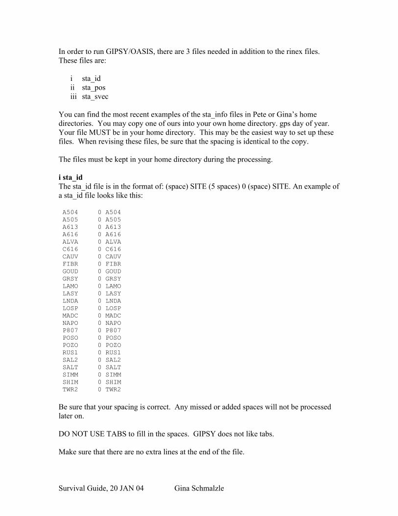
i sta_idThe sta_id file is in the format of: (space) SITE (5 spaces) 0 (space) SITE. An example of a sta_id file looks like this:
A504 0 A504 A505 0 A505 A613 0 A613 A616 0 A616 ALVA 0 ALVA C616 0 C616 CAUV 0 CAUV FIBR 0 FIBR GOUD 0 GOUD GRSY 0 GRSY LAMO 0 LAMO LASY 0 LASY LNDA 0 LNDA LOSP 0 LOSP MADC 0 MADC NAPO 0 NAPO P807 0 P807 POSO 0 POSO POZO 0 POZO RUS1 0 RUS1 SAL2 0 SAL2 SALT 0 SALT SIMM 0 SIMM SHIM 0 SHIM TWR2 0 TWR2
Be sure that your spacing is correct. Any missed or added spaces will not be processed later on.
DO NOT USE TABS to fill in the spaces. GIPSY does not like tabs.
Make sure that there are no extra lines at the end of the file.
Survival Guide, 20 JAN 04 Gina Schmalzle

ii sta_posThe sta_pos file comes in the form of:
(space) SITE (space)YYYY (space) MM (space) DD (space) HH (space) mm (space) SS.SS (space) (the amount of time (in days) the position is valid for) (15 spaces until the end of the next column) (earth center position x (m)) (14 spaces until the end of the next column) (earth center position y (m)) (14 spaces until the end of the next column) (earth center position z (m)) (15 spaces until the end of the next column) (earth velocity in x-direction in meters/yr; if not known then = 0.0000000E+00) (14 spaces until the end of the next column) (earth velocity in y-direction in meters/yr; if not known then = 0.00000000E+00) (14 spaces until the end of the next column) (earth velocity in x-direction in meters/yr; if not known then = 0.00000000E+00) (Comment:YYYY MM DD INT)
YYYY = yearMM = monthDD = dayHH = hourmm = minuteSS.SS = secondINT = initials of processor
An example of a sta_pos file looks like this: A504 1994 03 15 18 58 30.00 1000001.00 -2602485.0000 -4537278.0000 3638445.0000 0.00000000E-01 0.00000000E-01 0.00000000E-01 2005 07 26 GMS A505 1994 03 17 18 47 30.00 1000001.00 -2658546.0000 -4498184.0000 3645536.0000 0.00000000E-01 0.00000000E-01 0.00000000E-01 2005 07 26 GMS A613 1994 03 08 19 22 30.00 1000001.00 -2530704.0000 -4517228.0000 3711964.0000 0.00000000E-01 0.00000000E-01 0.00000000E-01 2005 07 26 GMS A616 1994 03 10 19 16 30.00 1000001.00 -2545588.0000 -4549722.0000 3662107.0000 0.00000000E-01 0.00000000E-01 0.00000000E-01 2005 07 26 GMS ALVA 1994 03 01 22 54 30.00 1000001.00 -2677094.0000 -4523659.0000 3600928.0000 0.00000000E-01 0.00000000E-01 0.00000000E-01 2005 07 26 GMS C616 1994 11 07 18 09 30.00 1000001.00 -2596978.0000 -4497992.0000 3690078.0000 0.00000000E-01 0.00000000E-01 0.00000000E-01 2005 07 26 GMS CAUV 1994 11 07 16 33 30.00 1000001.00 -2592500.0000 -4517446.0000 3671009.0000 0.00000000E-01 0.00000000E-01 0.00000000E-01 2005 07 26 GMS FIBR 1994 03 07 15 42 00.00 1000001.00 -2554674.0000 -4534924.0000 3674026.0000 0.00000000E-01 0.00000000E-01 0.00000000E-01 2005 07 26 GMS GOUD 1994 11 02 17 35 00.00 1000001.00 -2583737.0000 -4517626.0000 3675590.0000 0.00000000E-01 0.00000000E-01 0.00000000E-01 2005 07 26 GMS GRSY 1994 03 04 17 20 00.00 1000001.00 -2656668.0000 -4525635.0000 3613531.0000 0.00000000E-01 0.00000000E-01 0.00000000E-01 2005 07 26 GMS LAMO 1994 03 06 17 46 30.00 1000001.00 -2642123.0000 -4529287.0000 3619794.0000 0.00000000E-01 0.00000000E-01 0.00000000E-01 2005 07 26 GMS LASY 1994 11 04 19 50 00.00 1000001.00 -2598106.0000 -4507898.0000 3678414.0000 0.00000000E-01 0.00000000E-01 0.00000000E-01 2005 07 26 GMS LNDA 1994 03 09 18 54 00.00 1000001.00 -2640232.0000 -4518274.0000 3634325.0000 0.00000000E-01 0.00000000E-01 0.00000000E-01 2005 07 26 GMS LOSP 1994 03 02 19 45 30.00 1000001.00 -2666622.0000 -4507899.0000 3628469.0000 0.00000000E-01 0.00000000E-01 0.00000000E-01 2005 07 26 GMS MADC 1994 03 08 19 27 30.00 1000001.00 -2618499.0000 -4523125.0000 3645287.0000 0.00000000E-01 0.00000000E-01 0.00000000E-01 2005 07 26 GMS NAPO 1994 11 04 18 32 00.00 1000001.00 -2596247.0000 -4504210.0000 3683975.0000 0.00000000E-01 0.00000000E-01 0.00000000E-01 2005 07 26 GMS P807 1994 11 02 16 29 00.00 1000001.00 -2584426.0000 -4502907.0000 3692603.0000 0.00000000E-01 0.00000000E-01 0.00000000E-01 2005 07 26 GMS POSO 1994 11 05 16 49 30.00 1000001.00 -2607680.0000 -4496184.0000 3685407.0000 0.00000000E-01 0.00000000E-01 0.00000000E-01 2005 07 26 GMS POZO 1994 11 02 01 15 30.00 1000001.00 -2627936.0000 -4497409.0000 3669666.0000 0.00000000E-01 0.00000000E-01 0.00000000E-01 2005 07 26 GMS RUS1 1994 03 01 23 31 00.00 1000001.00 -2678535.0000 -4524296.0000 3598860.0000 0.00000000E-01 0.00000000E-01 0.00000000E-01 2005 07 26 GMS SAL2 1994 11 07 17 33 00.00 1000001.00 -2603657.0000 -4527542.0000 3650592.0000 0.00000000E-01 0.00000000E-01 0.00000000E-01 2005 07 26 GMS SALT 2003 10 30 01 04 45.00 1000001.00 -2603655.5653 -4527535.1218 3650597.8651 0.00000000E-01 0.00000000E-01 0.00000000E-01 2005 07 26 GMS SIMM 2003 10 21 23 19 45.00 1000001.00 -2604498.4671 -4510491.4418 3670051.4678 0.00000000E-01 0.00000000E-01 0.00000000E-01 2005 07 26 GMS SHIM 2005 05 20 17 21 15.00 1000001.00 939511.8554 -5688797.1663 2717613.1918 0.00000000E-01 0.00000000E-01 0.00000000E-01 2005 07 26 GMS TWR2 1993 05 09 04 35 00.00 1000001.00 -2601384.6240 -4502436.8153 3682565.9854 0.00000000E-01 0.00000000E-01 0.00000000E-01 2005 07 26 GMS
I purposely decreased the font size so that you can see how the columns line up. Be sure that the columns line up exactly in this format or GIPSY will not like you. Here is a normal sized line so you can better see the information it contains:
A504 1994 03 15 18 58 30.00 1000001.00 -2602485.0000 -4537278.0000 3638445.0000 0.00000000E-01 0.00000000E-01 0.00000000E-01 2005 07 26 GMS
The start date and time, as well as the position from the center of the earth in x, y and z is given in the rinex header. We use 1000001.00 as the default value for how long the position is good for.
Survival Guide, 20 JAN 04 Gina Schmalzle
The sta_pos file only needs one line of information per station. Be sure, however, that the line contains the dates and times and positions from the earliest occupation’s start time.
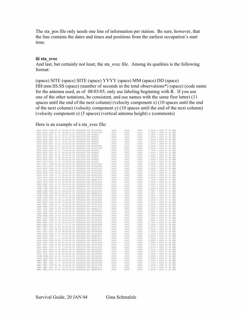
iii sta_svecAnd last, but certainly not least, the sta_svec file. Among its qualities is the following format:
(space) SITE (space) SITE (space) YYYY (space) MM (space) DD (space) HH:mm:SS.SS (space) (number of seconds in the total observations*) (space) (code name for the antenna used, as of 08/03/05, only use labeling beginning with R. If you use one of the other notations, be consistent, and use names with the same first letter) (11 spaces until the end of the next column) (velocity component x) (10 spaces until the end of the next column) (velocity component y) (10 spaces until the end of the next column) (velocity component z) (5 spaces) (vertical antenna height) c (comments)
Here is an example of a sta_svec file: A504 A504 1994 03 15 18:58:30.00 00864000.000 RT1453200 .0000 .0000 .0000 2.2200 c 2005 07 26 GMS A504 A504 1998 07 01 18:28:15.00 00864000.000 RT2202000 .0000 .0000 .0000 2.0000 c 2005 07 26 GMS A504 A504 2001 01 31 16:51:15.00 00014400.000 RT4800 .0000 .0000 .0000 1.6587 c 2005 07 26 GMS A504 A504 2001 02 01 16:41:15.00 00007500.000 RT4800 .0000 .0000 .0000 1.8009 c 2005 07 26 GMS A504 A504 2001 02 01 20:13:00.00 00086400.000 RT4800 .0000 .0000 .0000 1.5124 c 2005 07 26 GMS A504 A504 2001 10 17 15:07:10.00 00086400.000 RT4800 .0000 .0000 .0000 1.6076 c 2005 07 26 GMS A504 A504 2001 10 31 15:59:00.00 00086400.000 RT4800 .0000 .0000 .0000 1.5976 c 2005 07 26 GMS A504 A504 2003 10 31 21:16:15.00 00864000.000 RT2965900 .0000 .0000 .0000 0.5000 c 2005 07 26 GMS A505 A505 1994 03 17 18:47:30.00 00864000.000 RT1453200 .0000 .0000 .0000 2.2200 c 2005 07 26 GMS A505 A505 2001 01 31 17:04:45.00 00007800.000 RT4800 .0000 .0000 .0000 1.7378 c 2005 07 26 GMS A505 A505 2001 01 31 20:45:45.00 00009000.000 RT4800 .0000 .0000 .0000 1.5354 c 2005 07 26 GMS A505 A505 2001 02 01 16:15:15.00 00009000.000 RT4800 .0000 .0000 .0000 1.4653 c 2005 07 26 GMS A505 A505 2001 02 01 20:15:45.00 00009000.000 RT4800 .0000 .0000 .0000 1.5996 c 2005 07 26 GMS A505 A505 2001 11 06 16:25:45.00 00025200.000 RT4800 .0000 .0000 .0000 1.4893 c 2005 07 26 GMS A505 A505 2001 11 07 15:23:50.00 00864000.000 RT4800 .0000 .0000 .0000 1.5474 c 2005 07 26 GMS A613 A613 1994 03 08 19:22:30.00 00864000.000 RT1453200 .0000 .0000 .0000 2.2200 c 2005 07 26 GMS A613 A613 2003 10 18 02:18:45.00 00864000.000 RT2965900 .0000 .0000 .0000 0.5000 c 2005 07 26 GMS A616 A616 1994 03 10 19:16:30.00 00259200.000 RT1453200 .0000 .0000 .0000 2.2200 c 2005 07 26 GMS A616 A616 1998 06 26 19:05:30.00 00864000.000 RT2202000 .0000 .0000 .0000 2.0000 c 2005 07 27 GMS ALVA ALVA 1994 03 02 02:10:30.00 00864000.000 RT1453200 .0000 .0000 .0000 1.1276 c 2005 07 27 GMS C616 C616 1994 11 07 18:09:30.00 00001140.000 RT1453200 .0000 .0000 .0000 0.8252 c 2005 07 27 GMS C616 C616 1994 11 07 18:34:00.00 00086400.000 RT1453200 .0000 .0000 .0000 0.8293 c 2005 07 27 GMS C616 C616 2000 08 29 00:00:30.00 00864000.000 RAOAD/M_T .0000 .0000 .0000 1.1248 c 2005 07 27 GMS CAUV CAUV 1994 11 07 16:33:30.00 00432000.000 RT1453200 .0000 .0000 .0000 1.5463 c 2005 07 27 GMS CAUV CAUV 2003 10 19 22:03:15.00 00864000.000 RT2965900 .0000 .0000 .0000 0.5000 c 2005 07 27 GMS FIBR FIBR 1994 03 07 15:42:00.00 00086400.000 RT1453200 .0000 .0000 .0000 1.1418 c 2005 07 27 GMS FIBR FIBR 1994 03 09 19:17:00.00 00864000.000 RT1453200 .0000 .0000 .0000 2.2200 c 2005 07 27 GMS FIBR FIBR 1994 11 11 16:26:00.00 00432000.000 RT1453200 .0000 .0000 .0000 0.9857 c 2005 07 27 GMS FIBR FIBR 1999 08 25 23:49:00.00 00864000.000 RAOAD/M_T .0000 .0000 .0000 0.9827 c 2005 07 27 GMS FIBR FIBR 2003 10 18 00:00:15.00 00864000.000 RT2965900 .0000 .0000 .0000 0.5000 c 2005 07 27 GMS GOUD GOUD 1994 11 02 17:35:00.00 00864000.000 RT1453200 .0000 .0000 .0000 1.0034 c 2005 07 27 GMS GOUD GOUD 2003 10 18 21:38:45.00 00864000.000 RT2965900 .0000 .0000 .0000 0.5000 c 2005 07 27 GMS GRSY GRSY 1994 03 04 17:20:00.00 00432000.000 RT1453200 .0000 .0000 .0000 1.1510 c 2005 07 28 GMS GRSY GRSY 1994 03 17 18:52:00.00 00864000.000 RT1453200 .0000 .0000 .0000 2.2200 c 2005 07 28 GMS LAMO LAMO 1994 03 06 17:46:30.00 00864000.000 RT1453200 .0000 .0000 .0000 0.9230 c 2005 07 28 GMS LASY LASY 1994 11 04 19:50:00.00 00864000.000 RAOAD/M_T .0000 .0000 .0000 0.8325 c 2005 07 28 GMS LASY LASY 2003 10 21 21:58:15.00 00864000.000 RT2965900 .0000 .0000 .0000 0.5000 c 2005 07 28 GMS LNDA LNDA 1994 03 09 18:54:00.00 00864000.000 RT1453200 .0000 .0000 .0000 0.9825 c 2005 07 28 GMS LNDA LNDA 2003 10 27 23:36:00.00 00950400.000 RT2965900 .0000 .0000 .0000 0.5000 c 2005 07 28 GMS LOSP LOSP 1994 03 03 00:01:30.00 00864000.000 RT1453200 .0000 .0000 .0000 1.0265 c 2005 07 28 GMS MADC MADC 1994 03 08 19:27:30.00 00864000.000 RT1453200 .0000 .0000 .0000 1.0602 c 2005 07 28 GMS NAPO NAPO 1994 11 04 18:32:00.00 00864000.000 RT1453200 .0000 .0000 .0000 0.7441 c 2005 07 28 GMS NAPO NAPO 2003 10 23 17:57:15.00 00950400.000 RT2965900 .0000 .0000 .0000 0.5000 c 2005 07 28 GMS P807 P807 1994 11 02 16:29:00.00 00864000.000 RT1453200 .0000 .0000 .0000 0.8676 c 2005 07 28 GMS P807 P807 2000 08 29 03:56:00.00 00864000.000 RAOAD/M_T .0000 .0000 .0000 0.3522 c 2005 07 28 GMS P807 P807 2003 10 18 18:08:45.00 00864000.000 RT2965900 .0000 .0000 .0000 1.2440 c 2005 07 28 GMS POSO POSO 1994 11 05 16:49:30.00 00003600.000 RT1453200 .0000 .0000 .0000 0.7524 c 2005 07 28 GMS POSO POSO 1994 11 07 17:55:30.00 00453600.000 RAOAD/M_T .0000 .0000 .0000 0.8233 c 2005 07 28 GMS POSO POSO 1994 11 12 00:00:00.00 00864000.000 RAOAD/M_T .0000 .0000 .0000 0.8243 c 2005 07 28 GMS POSO POSO 2000 08 29 17:02:30.00 00864000.000 RAOAD/M_T .0000 .0000 .0000 0.9287 c 2005 07 28 GMS POZO POZO 1994 11 02 01:15:30.00 00864000.000 RT1453200 .0000 .0000 .0000 0.9839 c 2005 07 28 GMS RUS1 RUS1 1994 03 02 01:59:30.00 00864000.000 RT1453200 .0000 .0000 .0000 1.0725 c 2005 07 28 GMS SAL2 SAL2 1994 11 07 17:33:00.00 00023220.000 RT1453200 .0000 .0000 .0000 1.0136 c 2005 07 28 GMS SAL2 SAL2 1994 11 08 00:01:30.00 00864000.000 RT1453200 .0000 .0000 .0000 1.0131 c 2005 07 28 GMS SAL2 SAL2 2003 10 30 00:06:30.00 00864000.000 RT2965900 .0000 .0000 .0000 0.5000 c 2005 07 28 GMS SALT SALT 2003 10 30 01:04:45.00 00864000.000 RT2965900 .0000 .0000 .0000 0.9100 c 2005 07 28 GMS SIMM SIMM 2003 10 21 23:19:45.00 02160000.000 RT2965900 .0000 .0000 .0000 0.5000 c 2005 07 28 GMS SHIM SHIM 2005 05 20 17:21:15.00 00864000.000 RT2965900 .0000 .0000 .0000 0.5000 c 2005 07 28 GMS TWR2 TWR2 1993 05 09 04:35:00.00 00033900.000 RA700228A .0000 .0000 .0000 1.2614 c 2005 07 28 GMS TWR2 TWR2 1993 11 17 16:09:00.00 00864000.000 RA700228D .0000 .0000 .0000 1.1705 c 2005 07 28 GMS TWR2 TWR2 1996 05 09 15:54:00.00 00864000.000 RA700718A .0000 .0000 .0000 1.2579 c 2005 07 28 GMS TWR2 TWR2 2001 05 17 19:35:30.00 00864000.000 RAOAD/M_T .0000 .0000 .0000 1.3725 c 2005 07 28 GMS TWR2 TWR2 2003 03 26 18:43:30.00 00864000.000 RAOAD/M_T .0000 .0000 .0000 1.2614 c 2005 07 28 GMS
Survival Guide, 20 JAN 04 Gina Schmalzle

Once again, I shrank the font so that you can see how the columns align. This is how one row of data looks in a normal font size:
A504 A504 1994 03 15 18:58:30.00 00864000.000 RT1453200 .0000 .0000 .0000 2.2200 c 2005 07 26 GMS
Helpful sta_svec hints:
* The number of seconds in the total observation can always be more, but never less than the total amount of time the data was recorded for that site in that sitting. Therefore, since there are 86,400 seconds in one day, if the GPS were running without interruption for four days, then the number you will put is (86,400 x 4) = 345600.
If the antenna height changes, or the type of antenna changes, a new line must be added to the sta_svec file. For example, look at station A504 in the example listed above. Notice the station was repeated because the antenna height and type changed. If these parameters did not change for a given campaign, the station would not have to be repeated.
If the antenna type or height for any given site has changed, you must add another line with the new information. Be sure that the time in seconds from the previous occupation does not overlap into the next occupation time.
Be sure each line is in reverse chronological order ie, the most recent date is above the other dates.
The code names of the antennas used are found in /goa/sta_info/pcenter (Modified Mar 11, 2002 by Giovanni Sella). If your data was obtained using a tripod, then you may be given a slant height instead of the antenna height. In order to get the antenna height, you must have the radius of the antenna used. These antenna radii are located at http://www.ngs.noaa.gov/ANTCAL/Models/TRM_choice.html. And don’t forget a2+b2=c2!!!
The velocity components are .0000.
Anything put after the c is a comment. You can put whatever you want after the c, but you may want to try something useful, like the date the file is being processed and your initials, so that way if you mess up people know who to make fun of.
REMINDERS:
Be sure that the formatting is EXACTLY how you see it in the examples or you will be sorry. Don’t worry, it usually takes several attempts to get these files right.
Survival Guide, 20 JAN 04 Gina Schmalzle

Make sure your antenna heights and types are correct. You will need to have the site log sheets to verify the correct height. These log sheets may also be useful in interpreting other questions you may have.
The rinex files should be in your working directory, and the sta_info files should be in your home directory.
7. MAKING YOUR *.stacov AND *.gd FILESNow comes the fun part:(Updated August 3, 2005 by Pete and Gina)
Once in your working directory:
1. Type:
compress *.YYo
to compress the data. The file name should have a .Z at the end. The number of days for one process cannot exceed 100.
2. Type:
addst local >&log&
This command creates a directory for each day of rinex data. Within each daily dir/ a local station covariance (*.stacov) file is created, among other things. For example, if you collected data on May 19, 2005 at site SITE you will have a directory 05may19/ that contains your rinex file (now in long format), a qmfile (decimated binary version of your rinex) and hopefully a stacov file 05may19.stacov. For more information regarding*.stacov files or other files that will mysteriously appear in your daily directory, read the GIPSY-OASIS 2 manual (good luck with that) or ask Tim, Gina or Pete.
The log file you have created is important in troubleshooting. Here is what to look for:
Enter the file ‘log’ using your favorite text editor.
Search for the phrase ‘STA info’.
If, in these sections, a core is dumped, you had problems with your processing. This may be due to how many hours of data exist in the file. If the file contains less then an hour of data, then GIPSY will core dump. Pete and Gina try to use only rinex files with 6 or more hours of data. If there is a sufficient amount of data, then it could be a formatting error. Return to section 3. Description of Rinex files for more information.
Survival Guide, 20 JAN 04 Gina Schmalzle
If, it says, No sta_id, and/or, No sta_pos and/or No sta_svec, GIPSY had trouble reading your sta_info files. Return to the sta_info section for hints on fixing this problem.
If none of these dumps or warnings appears, then GIPSY successfully processed your data.
Once all of your stacov files are created:
Make a directory named stacov mkdir stacov
In your working directory, copy your stacov files into your new directory stacov by typing:
foreach d (YY*)cp $d/*.stacov stacov/end
Do this for each year being processed. This will copy all the stacov files into your new directory named stacov.
Change to your stacov directory
cd stacov/
List all of the stacov’s into a file called list:
ls *.stacov >list
Copy the command carriage from Pete’s directory. Also copy the program apply_igsb00_any into the directory for future use:
cp giotto/home/pete/bin/carriage .
cp giotto/home/pete/bin/apply_igsb00_any .
Use the carriage command to take the column list of stacovs and truncate the .stacov part. It will also put all the names in one line:
carriage < list > list2
In your favorite text editor, open list2 and create the following foreach loop:
#!/bin/cshforeach d (list of stacov dates)
Survival Guide, 20 JAN 04 Gina Schmalzle
splitcov $d.stacovend
Make sure you can execute list2:chmod u+x list2
Execute:list2
This splits your daily splitcov files into daily site specific stacov files (e.g., 05MAY19SITE.stacov).
bzip2 the *.stacov files:
bzip2 *.stacov
Make another file named “apply”.
Open apply and type:
#!/bin/cshforeach d (SITE1, SITE2…)apply_igsb00_any $dend
Make the file executable:
chmod u+x apply
Execute:apply
This applies the reference frame transformation parameters to your stacov file and outputs a transformed stacov (e.g., 05MAY19SITE.igsb00.stacov) and your *.gd files.
Create a new file and name it stats.Type:
#!/bin/cshforeach d (SITE1 SITE2 ….)stat $d.GD .end
Save and close the texteditor.
Type:
Survival Guide, 20 JAN 04 Gina Schmalzle
chmod u+x stats
Type:stats
This step creates your *.GD and *.GD.ps files. The positions are calculated for each day of data per site.
8. MERGING DIFFERENT YEARS IN YOUR *.GD FILES
Since, in this manual, we did not process different years separately, we do not have to worry about merging the data. If this is your case, then proceed to section 9.
Let’s say, however, that we have other years of pre-processed data that we would like to merge with our set of processed data for the same sites. In a new directory used specifically for placing the new merged files type:
cat /(directory your first yr’s data is in)/SITE.GD /(directory your second yr’s data is in)/SITE.GD > /(directory your merge will be in)/SITE.GD
9. CALCULATING ERROR
There are several different programs used to calculate error and show the individual site’s results: doerror and gmtplot. doerror may ONLY be done on Corsica. gmtplot may be used on any machine. The preferred is doerror because it also includes white and flicker noise. If you want to use doerror type:
doerror SITE.GD win3.0
If you want to use gmtplot type:
gmtplot SITE.GD win3.0
Enter the file you just made and remove the second header that separated the data for the two years (keep the first header). When the middle headers are removed, type:
gs SITE.GD.ps
to view your plot.
CREATING A VELOCITY PROFILE FROM PROCESSED DATA
In order to plot this data in a way that makes sense, it is useful to plot the data with respect to a stable reference frame. Usually, we will claim a plate to be stable, in other words, the plate is fixed, and we solve for the velocities of each site. In the example
Survival Guide, 20 JAN 04 Gina Schmalzle
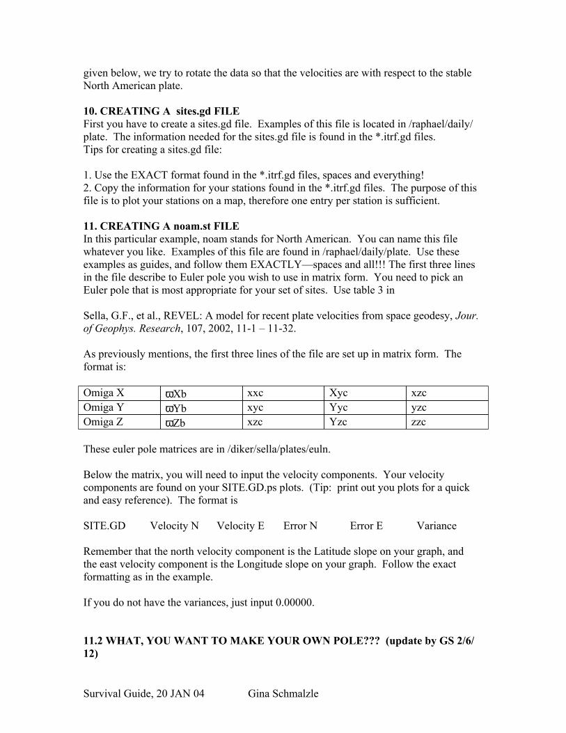
given below, we try to rotate the data so that the velocities are with respect to the stable North American plate.
10. CREATING A sites.gd FILEFirst you have to create a sites.gd file. Examples of this file is located in /raphael/daily/plate. The information needed for the sites.gd file is found in the *.itrf.gd files. Tips for creating a sites.gd file:
1. Use the EXACT format found in the *.itrf.gd files, spaces and everything!2. Copy the information for your stations found in the *.itrf.gd files. The purpose of this file is to plot your stations on a map, therefore one entry per station is sufficient.
11. CREATING A noam.st FILEIn this particular example, noam stands for North American. You can name this file whatever you like. Examples of this file are found in /raphael/daily/plate. Use these examples as guides, and follow them EXACTLY—spaces and all!!! The first three lines in the file describe to Euler pole you wish to use in matrix form. You need to pick an Euler pole that is most appropriate for your set of sites. Use table 3 in
Sella, G.F., et al., REVEL: A model for recent plate velocities from space geodesy, Jour. of Geophys. Research, 107, 2002, 11-1 – 11-32.
As previously mentions, the first three lines of the file are set up in matrix form. The format is:
Omiga X ωXb xxc Xyc xzcOmiga Y ωYb xyc Yyc yzcOmiga Z ωZb xzc Yzc zzc
These euler pole matrices are in /diker/sella/plates/euln. Below the matrix, you will need to input the velocity components. Your velocity components are found on your SITE.GD.ps plots. (Tip: print out you plots for a quick and easy reference). The format is
SITE.GD Velocity N Velocity E Error N Error E Variance Remember that the north velocity component is the Latitude slope on your graph, and the east velocity component is the Longitude slope on your graph. Follow the exact formatting as in the example.
If you do not have the variances, just input 0.00000.
11.2 WHAT, YOU WANT TO MAKE YOUR OWN POLE??? (update by GS 2/6/12)
Survival Guide, 20 JAN 04 Gina Schmalzle

The following commands will allow you to create a pole using vplate.
Let list.dat = the file that contains all the site names you wish to use for the pole. Let alldata.dat = your ITRF velocity field in the format:
Lon Lat Vn Ve Sn Se Corr Site
cat alldata.dat | egrep -f list.dat > subset.datvplate < subset.dat > mypole.stcat mypole.st alldata.dat > noam.stcp alldata.dat noam.dattouch noam.res
12. CREATING A noam.dat FILEMake a noam.dat file which is the same as the noam.st file but the Euler pole positions are not included.
13. CREATING A noam.res FILEMake a blank file and name it noam.res. This will be an input file.
14. CREATING YOUR VELOCITY MAPType: pvel < *.st > *.res
Then type: vmap *.res –diff
A file by the name of map.ps will be created. Type: gs map.ps
to view your results.
Survival Guide, 20 JAN 04 Gina Schmalzle