Embed Size (px)
Citation preview
BORNEO SCIENCE 29: SEPTEMBER 2011
46
SURVEY OF SLOPE FAILURES (SFS) ALONG THE BUNDU TUHAN
KUNDASANG HIGHWAY, SABAH, MALAYSIA
Rodeano Roslee, Sanudin Tahir, S. Abd. Kadir S. Omang & Adong Laming
School of Science and Technology, Universiti Malaysia Sabah, Jalan UMS, 88400 Kota
Kinabalu, Sabah
ABSTRACT. This study focused on the slope failures survey (SFS) along the Bundu Tuhan -
Kundasang highway, which is one of the most vulnerable areas to slope failures in west coast
of Sabah. The area is underlain the Trusmadi Formation (Palaeocene to Eocene age), the
Crocker Formation (Late Eocene to Early Miocene age) and Quaternary Alluvium Deposits.
These geologic units are dissected by numerous lineaments and structural styles produced by
complex tectonic history of multi phase deformations. The tectonic complexity reduces the
physical and mechanical properties of the rocks and soils; and produced intensive
displacements in substrata, resulting in intensive high degree of weathering processes and
instability. In this study, a total of 50 selected critical slopes were studied. This study
classified the slope failures into three main groups: soil slope failures, rock slope failures
and erosional failures. Failures in soil slopes (including embankments) total 34 (68 %) with
10 failures (20 %) of rock slopes and 6 failures (12 %) caused by erosion. Soil slope failures
normally involved large volume of failed material compared to rock slopes, where most
failures are small to large size. Of the 34 failures in soil slopes, 31 (91 %) are embankment
failures making them 62 % of all types of failures. Engineering geological evaluation of the
study area indicates that the slope failures took place when slope materials are no longer
able to resist the force of gravity. These decrease the shear strength and increase the shear
stress resulting slope failures, which is due to internal and external factors. Internal factors
involve some factors change in either physical or chemical properties of the rock or soil such
as topographic setting, climate, geologic setting and processes, groundwater condition and
engineering characteristics. External factors involve increase of shear stress on slopes,
which usually involves a form of disturbance that is induced by man includes removal of
vegetation cover, vehicles loading and artificial changes or natural phenomenon.
Development planning has to consider this disaster in order to mitigate their effect. An
landslide risk management program should be implemented to prevent these losses. This
engineering geological study will play a vital role in slope stability assessment to ensure the
public safety.
KEYWORDS: Slope failures survey (SFS), failure probability, physical and mechanical
properties
INTRODUCTION
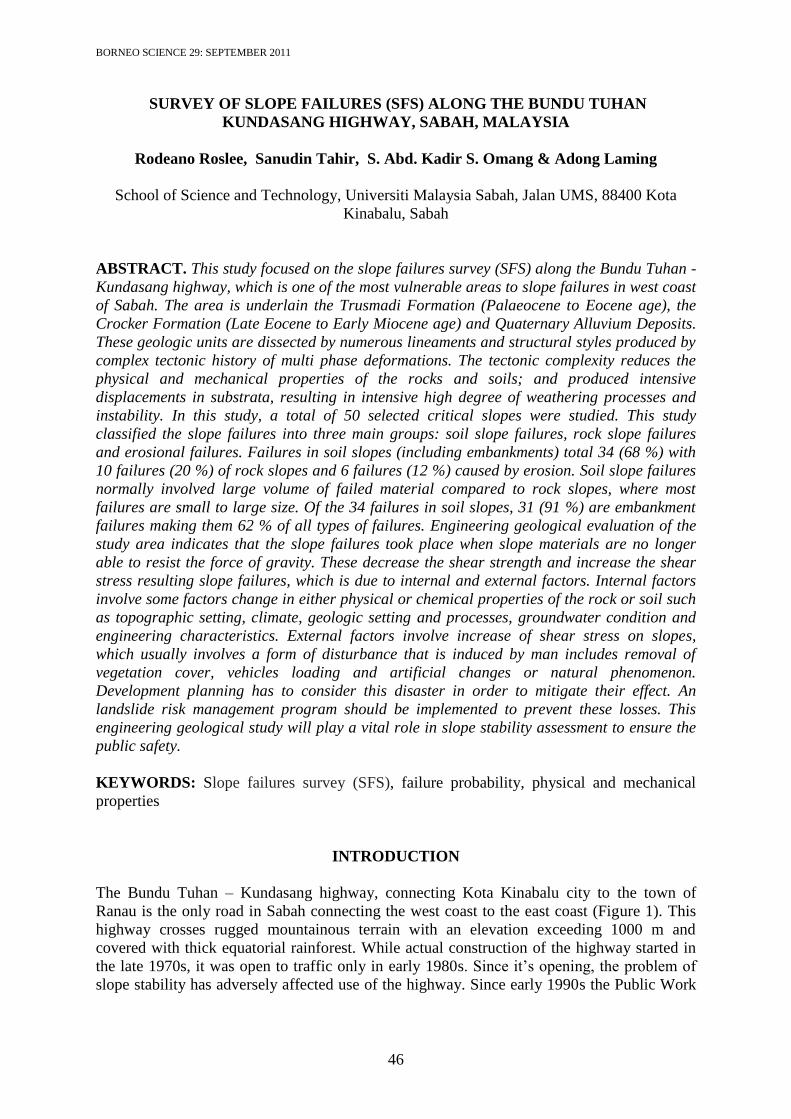
The Bundu Tuhan – Kundasang highway, connecting Kota Kinabalu city to the town of
Ranau is the only road in Sabah connecting the west coast to the east coast (Figure 1). This
highway crosses rugged mountainous terrain with an elevation exceeding 1000 m and
covered with thick equatorial rainforest. While actual construction of the highway started in
the late 1970s, it was open to traffic only in early 1980s. Since it’s opening, the problem of
slope stability has adversely affected use of the highway. Since early 1990s the Public Work
Survey Of Slope Failures (Sfs) Along The Bundu Tuhan Kundasang Highway, Sabah, Malaysia
47
Department of Malaysia (JKR) has started a program of repair and rehabilitation of slope
failures to improve the highway. This work is still going on today.
This paper deals with a slope failures survey (SFS) at 50 selected critical slopes along
the highway with the aim of identifying the main types of failures, the main factors
contributing to failures and the recommendation of mitigation measures. Generally, slope
failures is influenced by a variety of control factors, such as geology and topography, and
trigger factors, such as prolonged and/or heavy rains. Sometimes a combination of various
factors is responsible for failures. Many researchers have conducted SFS triggered by rainfall
(Ocakoglu et al., 2002; Petrucci & Polemio, 2003; Fiorillo & Wilson, 2004; Mikos et al.,
2004; Wen & Aydin, 2005; Mikos et al., 2006; Sivrikaya et al., 2008). It is commonly
recognized that the rainfall-induced slope failures are caused by excess pore pressures and
seepage forces during periods of intense rainfall. It is the excess pore water pressure that
decreases the effective stress in the rock and soil; and thus reduces the shear strength,
consequently resulting in failures (Anderson & Sitar, 1995). In recent years, many studies
have been published on debris flow and/or rainfall-induced slope failures (Chowdhury &
Flentje, 2002; Delmonaco et al., 2003; Teoman et al., 2004; Benac et al., 2005; Dunning et
al., 2006; Yilmaz & Yildirim, 2006; Wang et al., 2006; Ulusay et al., 2007; etc.).
Figure 1. Location of study area with their boreholes location and cross-section A-B
MATERIALS AND METHODS
Several classifications can be used to describe SFS method. A very complete classification
system for general use has been proposed by Terzaghi (1952), Varnes (1958 and 1978),
Zaruba & Mencl (1969 and 1982), Crozier (1986), Hutchison (1988) and Dikau et al. (1996).
For this study, the types of slope failures were classified according to the proposals of
Ibrahim Komoo (1985). In this system, slope failures were classified into three main groups:
soil slope failures, rock slope failures and special types of failures. Soil slope failures were
divided into slides (T1), slumps (T2), flows (T3), creep (T4) and complex failures (T5)
whereas rock slope failures were divided into circular (B1), plane (B2) and wedge failures
(B3) together with rock falls (B4). Erosional failure is considered as a special type of failures
(TB1). In this study, only failures with volumes exceeding 10 m3 were considered, as failures
of smaller volume did not generally affect road users. On this basis, the slope failures were
Rodeano Roslee, Sanudin Tahir, S. Abd. Kadir S. Omang & Adong Laming
48
divided into three groups: small (10 – 50 m3), medium (50 – 500 m
3) and large (> 500 m
3).
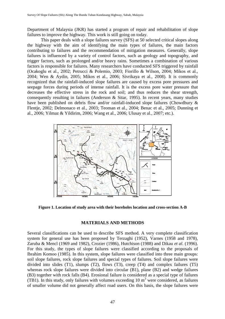
For each slope failures that was studied (Figure 2), the geometry of the slope, geological
background characteristics, weathering characteristics, ground water condition, discontinuity
characteristics, type of failures, physical and mechanical properties of the sliding materials
and an interpretation of the factors causing the failure were recorded. Soil and rock samples
from the study area were collected during field mapping for detailed laboratory analysis. The
laboratory works such as classification tests (grain size, atterberg limit, shrinkage limit,
specific gravity and water content), permeability test, consolidated isotropically undrained
(CIU) test, rock uniaxial compressive strength and point load test were carried out in
compliance and accordance to British Standard Code of Practice BS 5930-1981 (Site
Investigation), British Standard Code of Practice BS 1377-1990 (Method of Test for Soils for
Civil Engineering Purposes) and ISRM (1979a, 1979b & 1985). Besides of those, intensive
literature review also has been done in order to obtain the useful reference and additional
information of the study area.
Figure 2. Location of slopes instability along highway
HYDROLOGIC AND HYDROGEOLOGIC SETTING
The highway and its surrounding area show a high drainage density with patterns (trellis,
annular and parallel) (Figure 2). The structural control of the river tributaries of the area is
evidenced by the physical characteristics of sedimentary rocks; highly fractured areas and
less competent shale beds. The sedimentary rocks are more intensely dissected by fault zones
than the ultrabasic rocks. Groundwater occurs and moves through interstices or secondary
pore openings in the rock formations. Such openings can be the pore spaces between
individual sedimentary grains, open joints and fractures in hard rocks or solution and
cavernous opening in brecciated layers and cataclasites. The direction of groundwater
movement is generally under the influence of gravity. The rock formations exhibit a high
degree of weathering and covered by thick residual soil that extends to more than 65 feet in
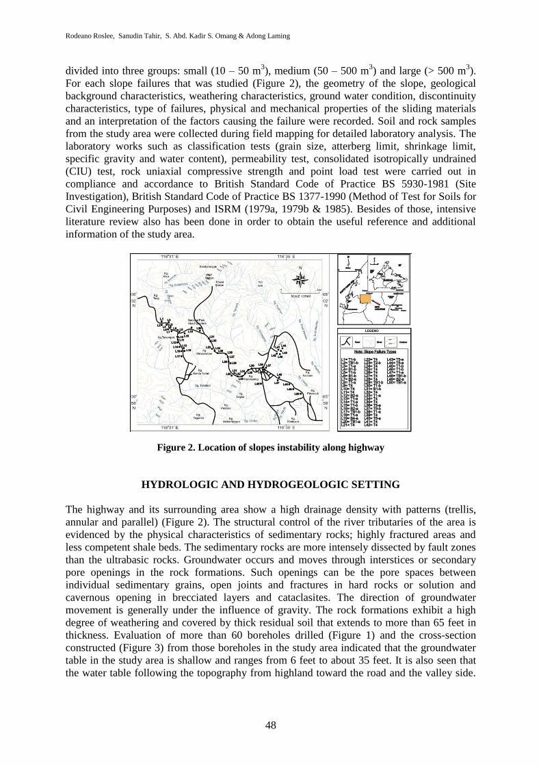
thickness. Evaluation of more than 60 boreholes drilled (Figure 1) and the cross-section
constructed (Figure 3) from those boreholes in the study area indicated that the groundwater
table in the study area is shallow and ranges from 6 feet to about 35 feet. It is also seen that
the water table following the topography from highland toward the road and the valley side.
Slopes Instability Survey (SIV) Along The Bundu Tuhan-Kundasang Highway, Sabah, Malaysia
Survey Of Slope Failures (Sfs) Along The Bundu Tuhan Kundasang Highway, Sabah, Malaysia
49
The weathered materials are weak and caused slope failures due to high pore pressure
subjected by both shallow and deep groundwater.
Figure 3. Cross – sectional A-B of groundwater table (From Figure 1)
GEOLOGY BACKGROUND
The local geology of the study area is made up of sedimentary rock of the Trusmadi
Formation (Palaeocene to Eocene age), the Crocker Formation (Late Eocene to Early
Miocene age) and the Quaternary Alluvium Deposits (Table 1 and Figure 4).
Table 1. Local Stratigraphic Column and their Water Bearing and Engineering
Properties
Age Rock
Formation Unit General Character Water-Bearing Properties Engineering Properties
Quaternary Alluvium -
Unconsolidated gravel, sand and silt with
minor amounts of clay deposited along the
rivers or streams and their tributaries.
Includes natural levee and flood plain
deposit.
Gravelly and sandy, portions
are highly permeable and
yield large quantities of
water. Important to
groundwater development.
Generally poorly consolidated.
Hence not suitable for heavy
structures and subsidence under
heavy load.
Late Eocene to
Early Miocene
Crocker
Formation
Shale
This unit is composed of two types of shale
red and grey. It is a sequence of alteration of
shale with siltstone of very fine.
It has no significant to
groundwater development
due to its impermeable
characteristic.
Very dangerous site for heavy
structures and the main causes of
mass movement.
Interbedded
Shale-Sandstone
It is a sequence of interlayering of permeable
sandstone with impermeable shale. The
permeability of this unit is quite variable.
Groundwater in this unit tends to be under
semi-confined to confined system.
Little importance to
groundwater provides some
water but not enough for
groundwater development.
Dangerous site for heavy structures
and high potential for mass
movement.
Sandstone
Light grey to cream colour, medium to
coarse -grained and some time pebbly. It is
highly folded, faulted, jointed, fractured
occasionally cavernous, surfically oxidized
and exhibits spheriodal weathering.
Importance to groundwater.
Good site for heavy structures with
careful investigation. Stable from
mass movement and provide some
modification like closing of
continuous structure.
Paleocene to
Eocene
Trusmadi
Formation
Trusmadi Slate
and Trusmadi
Phyllite
Comprise of dark colour argillaceous rock
either in thick bedded or interbedded with
thin sandstone beds reported along with
isolated exposures of volcanic rock is a
common feature of this formation.
Fractured sandstone has
significant to groundwater.
Dangerous site for heavy structure.
Improvement should be conducted
before any project.
Rodeano Roslee, Sanudin Tahir, S. Abd. Kadir S. Omang & Adong Laming
50
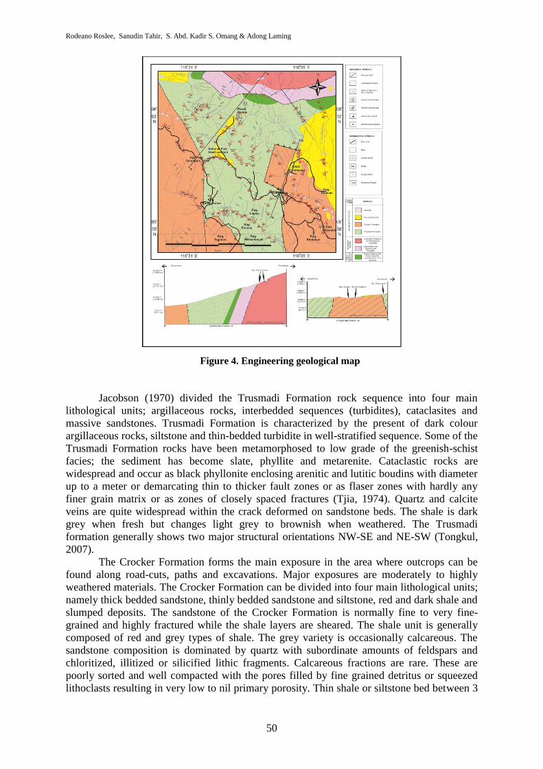
Figure 4. Engineering geological map
Jacobson (1970) divided the Trusmadi Formation rock sequence into four main
lithological units; argillaceous rocks, interbedded sequences (turbidites), cataclasites and
massive sandstones. Trusmadi Formation is characterized by the present of dark colour
argillaceous rocks, siltstone and thin-bedded turbidite in well-stratified sequence. Some of the
Trusmadi Formation rocks have been metamorphosed to low grade of the greenish-schist
facies; the sediment has become slate, phyllite and metarenite. Cataclastic rocks are
widespread and occur as black phyllonite enclosing arenitic and lutitic boudins with diameter
up to a meter or demarcating thin to thicker fault zones or as flaser zones with hardly any
finer grain matrix or as zones of closely spaced fractures (Tjia, 1974). Quartz and calcite
veins are quite widespread within the crack deformed on sandstone beds. The shale is dark
grey when fresh but changes light grey to brownish when weathered. The Trusmadi
formation generally shows two major structural orientations NW-SE and NE-SW (Tongkul,
2007).
The Crocker Formation forms the main exposure in the area where outcrops can be
found along road-cuts, paths and excavations. Major exposures are moderately to highly
weathered materials. The Crocker Formation can be divided into four main lithological units;
namely thick bedded sandstone, thinly bedded sandstone and siltstone, red and dark shale and
slumped deposits. The sandstone of the Crocker Formation is normally fine to very fine-
grained and highly fractured while the shale layers are sheared. The shale unit is generally
composed of red and grey types of shale. The grey variety is occasionally calcareous. The
sandstone composition is dominated by quartz with subordinate amounts of feldspars and
chloritized, illitized or silicified lithic fragments. Calcareous fractions are rare. These are
poorly sorted and well compacted with the pores filled by fine grained detritus or squeezed
lithoclasts resulting in very low to nil primary porosity. Thin shale or siltstone bed between 3
Survey Of Slope Failures (Sfs) Along The Bundu Tuhan Kundasang Highway, Sabah, Malaysia
51
to 40 cm thicknesses occurred between the thick sandstone beds. The argillaceous beds are
frequently site of shearing while the sandstone beds site of fracturing or jointing.
The alluvium is restricted to the low land. It mainly represent unconsolidated alluvial
sediment on river terraces composed of unsorted to well-sorted, sand, silt and clay of varying
proportions which were derived from upstream bed rocks. They occur in irregular lenses
varying in the form and thickness. The alluvium may also consist of very thin layer of
organic matter. The alluvium sediment is soft, compressible and may be prone to settlement.
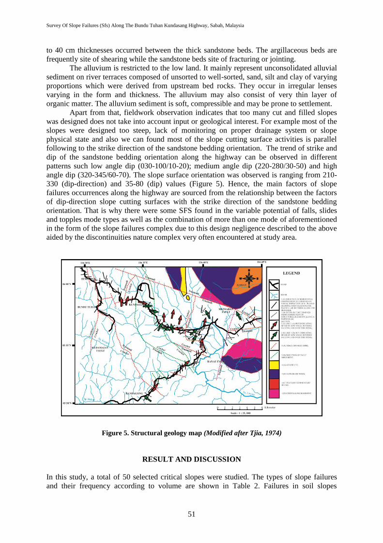
Apart from that, fieldwork observation indicates that too many cut and filled slopes
was designed does not take into account input or geological interest. For example most of the
slopes were designed too steep, lack of monitoring on proper drainage system or slope
physical state and also we can found most of the slope cutting surface activities is parallel
following to the strike direction of the sandstone bedding orientation. The trend of strike and
dip of the sandstone bedding orientation along the highway can be observed in different
patterns such low angle dip (030-100/10-20); medium angle dip (220-280/30-50) and high
angle dip (320-345/60-70). The slope surface orientation was observed is ranging from 210-
330 (dip-direction) and 35-80 (dip) values (Figure 5). Hence, the main factors of slope
failures occurrences along the highway are sourced from the relationship between the factors
of dip-direction slope cutting surfaces with the strike direction of the sandstone bedding
orientation. That is why there were some SFS found in the variable potential of falls, slides
and topples mode types as well as the combination of more than one mode of aforementioned
in the form of the slope failures complex due to this design negligence described to the above
aided by the discontinuities nature complex very often encountered at study area.
Figure 5. Structural geology map (Modified after Tjia, 1974)
RESULT AND DISCUSSION
In this study, a total of 50 selected critical slopes were studied. The types of slope failures
and their frequency according to volume are shown in Table 2. Failures in soil slopes
Rodeano Roslee, Sanudin Tahir and S. Abd. Kadir S. Omang
Rodeano Roslee, Sanudin Tahir and S. Abd. Kadir S. Omang
Rodeano Roslee, Sanudin Tahir, S. Abd. Kadir S. Omang & Adong Laming
52
(including embankments) total 34 (68 %) with 10 failures (20 %) of rock slopes and 6 failures
(12 %) caused by erosion. Soil slope failures normally involved large volume of failed
material compared to rock slopes, where most failures are small to large size. Of the 34
failures in soil slopes, 31 (91 %) are embankment failures making them 62 % of all types of
failures.
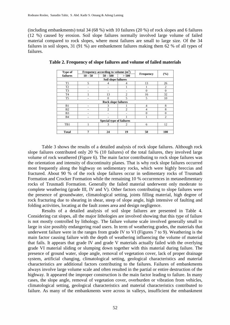
Table 2. Frequency of slope failures and volume of failed materials
Type of
failures
Frequency according to volume (m3) Frequency (%)
10 – 50 50 – 500 > 500
Soil slope failures
T1 5 4 4 13 26
T2 - - 1 1 2
T3 - - - 0 0
T4 1 13 2 16 32
T5 - 0 5 5 10
Rock slope failures
B1 - 3 1 4 8
B2 - 2 2 4 8
B3 - - - 0 0
B4 - - 1 1 2
Special type of failures
TB1 1 3 2 6 12
Total 7 24 19 50 100
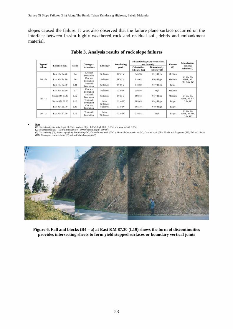
Table 3 shows the results of a detailed analysis of rock slope failures. Although rock
slope failures contributed only 20 % (10 failures) of the total failures, they involved large
volume of rock weathered (Figure 6). The main factor contributing to rock slope failures was
the orientation and intensity of discontinuity planes. That is why rock slope failures occurred
most frequently along the highway on sedimentary rocks, which were highly breccias and
fractured. About 90 % of the rock slope failures occur in sedimentary rocks of Trusmadi
Formation and Crocker Formation while the remaining 10 % occurrences in metasedimentary
rocks of Trusmadi Formation. Generally the failed material underwent only moderate to
complete weathering (grade III, IV and V). Other factors contributing to slope failures were
the presence of groundwater, climatological setting, joints filling material, high degree of
rock fracturing due to shearing in shear, steep of slope angle, high intensive of faulting and
folding activities, locating at the fault zones area and design negligence.
Results of a detailed analysis of soil slope failures are presented in Table 4.
Considering cut slopes, all the major lithologies are involved showing that this type of failure
is not mostly controlled by lithology. The failure volume scale involved generally small to
large in size possibly endangering road users. In term of weathering grades, the materials that
underwent failure were in the ranges from grade IV to VI (Figures 7 to 9). Weathering is the
main factor causing failure with the depth of weathering influencing the volume of material
that fails. It appears that grade IV and grade V materials actually failed with the overlying
grade VI material sliding or slumping down together with this material during failure. The
presence of ground water, slope angle, removal of vegetation cover, lack of proper drainage
system, artificial changing, climatological setting, geological characteristics and material
characteristics are additional factors contributing to the failures. Failures of embankments
always involve large volume scale and often resulted in the partial or entire destruction of the
highway. It appeared the improper construction is the main factor leading to failure. In many
cases, the slope angle, removal of vegetation cover, overburden or vibration from vehicles,
climatological setting, geological characteristics and material characteristics contributed to
failure. As many of the embankments were across in valleys, insufficient the embankment
Survey Of Slope Failures (Sfs) Along The Bundu Tuhan Kundasang Highway, Sabah, Malaysia
53
slopes caused the failure. It was also observed that the failure plane surface occurred on the
interface between in-situ highly weathered rock and residual soil, debris and embankment
material.
Table 3. Analysis results of rock slope failures
Type of
failures Location (km) Slope
Geological
formations Lithology
Weathering
grade
Discontinuity plane orientation
and intensity Volume
(2)
Main factors
causing
failures (3) Orientation
(Strike / dip)
Discontinuity
Intensity (1)
B1 – b
East KM 84.40
East KM 84.90
East KM 92.50
L4
L6
L31
Crocker
Formation
Crocker
Formation
Trusmadi
Formation
Sediment
Sediment
Sediment
IV to V
IV to V
IV to V
345/76
010/62
110/50
Very High
Very High
Very High
Medium
Medium
Large
D, SA, W,
GWL, M,
CR, G & AC
B2 – a
East KM 85.50
South KM 87.45
South KM 87.90
East KM 95.70
L7
L12
L16
L49
Crocker
Formation
Trusmadi
Formation
Trusmadi
Formation
Crocker
Formation
Sediment
Sediment
Meta
Sediment
Sediment
III to IV
IV to V
III to IV
III to IV
350/58
190/73
185/43
085/18
High
Very High
Very High
Very High
Medium
Medium
Large
Large
D, SA, W,
GWL, M, BF,
G & AC
B4 – a East KM 87.30 L19 Trusmadi
Formation
Meta
Sediment III to IV 310/54 High Large
D, SA, W,
GWL, M, FB,
G & AC
Note
(1) Discontinuity intensity: low (< 0.5/m), medium (0.5 – 1.0/m), high (1.0 – 5.0/m) and very high (> 5.0/m)
(2) Volume: small (10 – 50 m3), Medium (50 – 500 m3) and Large (> 500 m3)
(3) Discontinuity (D), Slope angle (SA), Weathering (W), Groundwater level (GWL), Material characterist ics (M), Crushed rock (CR), Blocks and fragments (BF), Fall and blocks
(FB), Geological characteristics (G) and artificial changing (AC)
Figure 6. Fall and blocks (B4 – a) at East KM 87.30 (L19) shows the form of discontinuities
provides intersecting sheets to form yield stepped surfaces or boundary vertical joints
Rodeano Roslee, Sanudin Tahir, S. Abd. Kadir S. Omang & Adong Laming
54
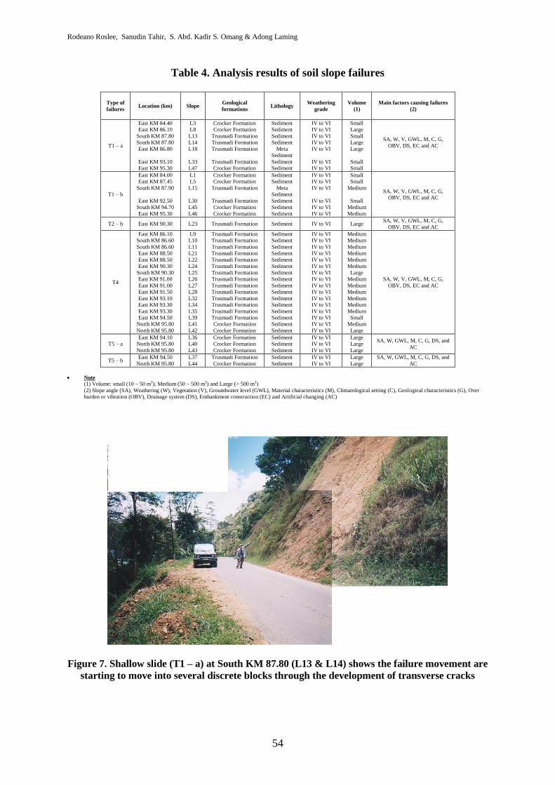
Table 4. Analysis results of soil slope failures
Type of
failures Location (km) Slope
Geological
formations Lithology
Weathering
grade
Volume
(1)
Main factors causing failures
(2)
T1 – a
East KM 84.40
East KM 86.10
South KM 87.80
South KM 87.80
East KM 86.80
East KM 93.10
East KM 95.30
L3
L8
L13
L14
L18
L33
L47
Crocker Formation
Crocker Formation
Trusmadi Formation
Trusmadi Formation
Trusmadi Formation
Trusmadi Formation
Crocker Formation
Sediment
Sediment
Sediment
Sediment
Meta
Sediment
Sediment
Sediment
IV to VI
IV to VI
IV to VI
IV to VI
IV to VI
IV to VI
IV to VI
Small
Large
Small
Large
Large
Small
Small
SA, W, V, GWL, M, C, G,
OBV, DS, EC and AC
T1 – b
East KM 84.00
East KM 87.45
South KM 87.90
East KM 92.50
South KM 94.70
East KM 95.30
L1
L5
L15
L30
L45
L46
Crocker Formation
Crocker Formation
Trusmadi Formation
Trusmadi Formation
Crocker Formation
Crocker Formation
Sediment
Sediment
Meta
Sediment
Sediment
Sediment
Sediment
IV to VI
IV to VI
IV to VI
IV to VI
IV to VI
IV to VI
Small
Small
Medium
Small
Medium
Medium
SA, W, V, GWL, M, C, G,
OBV, DS, EC and AC
T2 – b East KM 90.30 L23 Trusmadi Formation Sediment IV to VI Large SA, W, V, GWL, M, C, G,
OBV, DS, EC and AC
T4
East KM 86.10
South KM 86.60
South KM 86.60
East KM 88.50
East KM 88.50
East KM 90.30
South KM 90.30
East KM 91.00
East KM 91.00
East KM 91.50
East KM 93.10
East KM 93.30
East KM 93.30
East KM 94.50
North KM 95.80
North KM 95.80
L9
L10
L11
L21
L22
L24
L25
L26
L27
L28
L32
L34
L35
L39
L41
L42
Trusmadi Formation
Trusmadi Formation
Trusmadi Formation
Trusmadi Formation
Trusmadi Formation
Trusmadi Formation
Trusmadi Formation
Trusmadi Formation
Trusmadi Formation
Trusmadi Formation
Trusmadi Formation
Trusmadi Formation
Trusmadi Formation
Trusmadi Formation
Crocker Formation
Crocker Formation
Sediment
Sediment
Sediment
Sediment
Sediment
Sediment
Sediment
Sediment
Sediment
Sediment
Sediment
Sediment
Sediment
Sediment
Sediment
Sediment
IV to VI
IV to VI
IV to VI
IV to VI
IV to VI
IV to VI
IV to VI
IV to VI
IV to VI
IV to VI
IV to VI
IV to VI
IV to VI
IV to VI
IV to VI
IV to VI
Medium
Medium
Medium
Medium
Medium
Medium
Large
Medium
Medium
Medium
Medium
Medium
Medium
Small
Medium
Large
SA, W, V, GWL, M, C, G,
OBV, DS, EC and AC
T5 – a
East KM 94.10
North KM 95.80
North KM 95.80
L36
L40
L43
Crocker Formation
Crocker Formation
Crocker Formation
Sediment
Sediment
Sediment
IV to VI
IV to VI
IV to VI
Large
Large
Large
SA, W, GWL, M, C, G, DS, and
AC
T5 – b East KM 94.50
North KM 95.80
L37
L44
Trusmadi Formation
Crocker Formation
Sediment
Sediment
IV to VI
IV to VI
Large
Large
SA, W, GWL, M, C, G, DS, and
AC
Note (1) Volume: small (10 – 50 m3), Medium (50 – 500 m3) and Large (> 500 m3)
(2) Slope angle (SA), Weathering (W), Vegetation (V), Groundwater level (GWL), Material characteristics (M), Climatological setting (C), Geological characteristics (G), Over
burden or vibration (OBV), Drainage system (DS), Embankment construction (EC) and Artificial changing (AC)
Figure 7. Shallow slide (T1 – a) at South KM 87.80 (L13 & L14) shows the failure movement are
starting to move into several discrete blocks through the development of transverse cracks
Survey Of Slope Failures (Sfs) Along The Bundu Tuhan Kundasang Highway, Sabah, Malaysia
55
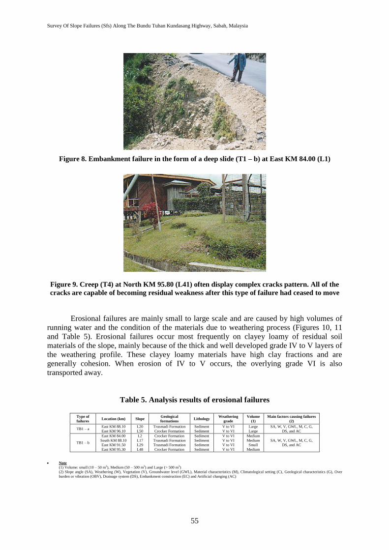
Figure 8. Embankment failure in the form of a deep slide (T1 – b) at East KM 84.00 (L1)
Figure 9. Creep (T4) at North KM 95.80 (L41) often display complex cracks pattern. All of the
cracks are capable of becoming residual weakness after this type of failure had ceased to move
Erosional failures are mainly small to large scale and are caused by high volumes of
running water and the condition of the materials due to weathering process (Figures 10, 11
and Table 5). Erosional failures occur most frequently on clayey loamy of residual soil
materials of the slope, mainly because of the thick and well developed grade IV to V layers of
the weathering profile. These clayey loamy materials have high clay fractions and are
generally cohesion. When erosion of IV to V occurs, the overlying grade VI is also
transported away.
Table 5. Analysis results of erosional failures
Type of
failures Location (km) Slope
Geological
formations Lithology
Weathering
grade
Volume
(1)
Main factors causing failures
(2)
TB1 – a East KM 88.10
East KM 96.10
L20
L50
Trusmadi Formation
Crocker Formation
Sediment
Sediment
V to VI
V to VI
Large
Large
SA, W, V, GWL, M, C, G,
DS, and AC
TB1 – b
East KM 84.00
South KM 88.10
East KM 91.50
East KM 95.30
L2
L17
L29
L48
Crocker Formation
Trusmadi Formation
Trusmadi Formation
Crocker Formation
Sediment
Sediment
Sediment
Sediment
V to VI
V to VI
V to VI
V to VI
Medium
Medium
Small
Medium
SA, W, V, GWL, M, C, G,
DS, and AC
Note
(1) Volume: small (10 – 50 m3), Medium (50 – 500 m3) and Large (> 500 m3)
(2) Slope angle (SA), Weathering (W), Vegetation (V), Groundwater level (GWL), Material characteristics (M), Climatological setting (C), Geological characteristics (G), Over
burden or vibration (OBV), Drainage system (DS), Embankment construction (EC) and Artificial changing (AC)
Rodeano Roslee, Sanudin Tahir, S. Abd. Kadir S. Omang & Adong Laming
56
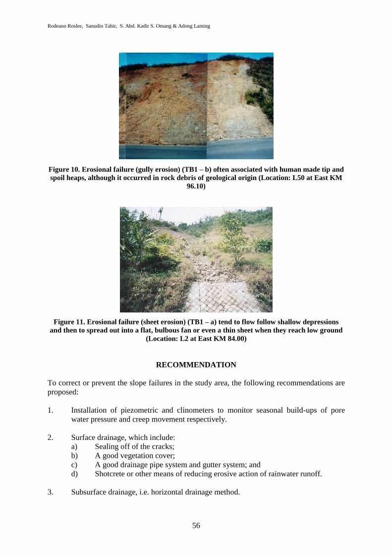
Figure 10. Erosional failure (gully erosion) (TB1 – b) often associated with human made tip and
spoil heaps, although it occurred in rock debris of geological origin (Location: L50 at East KM
96.10)
Figure 11. Erosional failure (sheet erosion) (TB1 – a) tend to flow follow shallow depressions
and then to spread out into a flat, bulbous fan or even a thin sheet when they reach low ground
(Location: L2 at East KM 84.00)
RECOMMENDATION
To correct or prevent the slope failures in the study area, the following recommendations are
proposed:
1. Installation of piezometric and clinometers to monitor seasonal build-ups of pore
water pressure and creep movement respectively.
2. Surface drainage, which include:
a) Sealing off of the cracks;
b) A good vegetation cover;
c) A good drainage pipe system and gutter system; and
d) Shotcrete or other means of reducing erosive action of rainwater runoff.
3. Subsurface drainage, i.e. horizontal drainage method.
Survey Of Slope Failures (Sfs) Along The Bundu Tuhan Kundasang Highway, Sabah, Malaysia
57
In light of available information, the following conclusion may be drawn from the present
study:
1. A total of 50 selected critical slope failures were studied. Failures in soil slopes
(including embankments) total 35 (70 %) with 10 failures (18 %) of rock slopes and 6
failures (12 %) caused by erosion. Soil slope failures normally involved large volume
of failed material compared to rock slopes, where most failures are small to large size.
Of the 35 failures in soil slopes, 31 (89 %) are embankment failures making them 62
% of all types of failures.
2. Geologic evaluation of the study area indicates that the slope failures took place when
slope materials are no longer able to resist the force of gravity. These decrease the
shear strength and increase the shear stress resulting slope failures, which is due to
internal and external factors. Internal factors involve some factors change in either
physical or chemical properties of the rock or soil such as topographic setting,
climate, geologic setting and processes, groundwater condition and engineering
characteristics. External factors involve increase of shear stress on slope, which
usually involves a form of disturbance that is induced by man includes removal of
vegetation cover, vehicles loading or vibration and artificial changes or natural
phenomenon such as tremors.
ACKNOWLEDGEMENTS
A lot of thanks to the Universiti Malaysia Sabah (UMS) on ease of use in laboratory and
fieldwork equipments. The highest appreciation is also given to the Ministry of Education
(MOE) on fundamental research grant award (B-0201-01-ER/U0038) to finance all costs of
research.
REFERENCES
Anderson, S.A. & Sitar, N. 1995. Analysis of rainfall-induced debris flows. J. Geotech. Eng.
121: 544–552.
Benac, C., Arbanas, I., Jurak, V., Ostric, M. & Ozanic, N. 2005. Complex landslide in the
Rjecina valley (Croatia): origin & sliding mechanism. Bull. Eng. Environ. 64: 361–371.
British Standard BS 5930. 1981. Site Investigation. London: British Standard Institution.
British Standard BS 1377. 1990. Methods of Test for Soils for Civil Engineering Purposes.
London: British Standard Institution.
Collenette, P. 1958. The geology & mineral resources of the Jeselton – Kinabalu area, North
Borneo. Borneo Geological Survey Department. Memoir 6.
Chowdhury, R. & Flentje, P. 2002. Uncertainties in rainfall-induced landslide hazard. Q.J.
Eng. Geol. Hydrogeol. 35: 61–69.
Crozier, M.J. 1986. Landslides: Causes, Consequences & Environment. Routledge. London.
Delmonaco, G., Leoni, G., Margottini, C., Puglisi, C, & Spizzichino, D. 2003. Large scale
debris-flow hazard assessment: a geotechnical approach & GIS modeling. Nat. Hazards
Earth Syst. Sci. 3: 443–455.
Rodeano Roslee, Sanudin Tahir, S. Abd. Kadir S. Omang & Adong Laming
58
Dikau, R., Brunsden, D., Schrott, L. & Ibsen, M.L. 1996. Landslide recognition -
identification, movement & causes. New York: John Wiley and Sons.
Dunning, S.A., Rosser, N.J. & Massey, C.R. 2006. Formation & failure of the Tsatichhu
landslide dam, Bhutan. Landslides 3: 107–113.
Fiorillo, F. & Wilson, R.C. 2004. Rainfall induced debris flows in pyroclastic deposits,
Campania (southern Italy). Eng. Geol. 75: 263–289.
Hutchison, J.N. 1988. Morphological & geotechnical parameters of landslides in relation to
geology & hydrology. General Report. In Landslides, Proc. 5th
. Int. Sym. On
Landslides (Ed. C. Bonnard), Vol. 1.
Ibrahim Komoo. 1985. Pengelasan Kegagalan Cerun di Malaysia. Jurnal Ilmu Alam. 14&15.
ISRM. 1979a. Suggested methods for determining water content, porosity, density,
absorption & related properties, & swelling and slake-durability index properties. ISRM
Commission on Standardization of Laboratory & Field Tests. Int. J. Rock Mech. Min.
Sci., 16, 141-156.
ISRM. 1979b. Suggested methods for determining the uniaxial compressive strength &
deformability of rock materials. ISRM Commission on Standardization of Laboratory &
Field Tests. Int. J. Rock Mech. Min. Sci., 16, 135-140.
ISRM. 1985. Suggested methods for determining point load strength. ISRM Commission on
Standardization of Laboratory & Field Tests. Int. J. Rock Mech. Min. Sci., 22 (2), 51-
60.Mikos, M,, Cetina, M. & Brilly, M. 2004. Hydrologic conditions responsible for
triggering the Stoze landslide, Slovenia. Eng. Geol. 73: 193–213.
Jacobson, G. 1970. Gunong Kinabalu area, Sabah, Malaysia. Geological Survey Malaysia.
Report 8.
Mikos, M., Brilly, M., Fazarnic, R. & Ribicic, M. 2006. Strug landslide in W Slovenia: a
complex multi-process phenomenon. Eng. Geol. 83: 22–35.
Ocakoglu, F., Gokceoglu, C. & Ercanoglu, M. 2002. Dynamics of a complex mass movement
triggered by heavyrainfall: a case study from NW Turkey. Geomorphology 42: 329–
341.
Petrucci, O. & Polemio, M. 2003. The use of historical data for the characterisation of
multiple damaging hydrogeological events. Nat. Hazards Earth Syst. 3: 17–3.
Sivrikaya, O., Kilic, A.M., Yalcin, M.G., Aykamis, A.S. & Sonmez, M. 2008. The 2001
Adana landslide & its destructive effects, Turkey. Environ. Geol. 54:1489–1500.
Teoman, M.B., Topal, T. & Isik, N.S. 2004. Assessment of slope stability in Ankara clay: a
case study along E90 highway. Environ. Geol. 45: 963–977.
Terzaghi, K. 1952. Mechanism of landslides. Geol. Soc. A. Berkey Volume.
Tjia, H. D. 1974. Sense of tectonic transport in intensely deformed Trusmadi & Crocker
sediments, Ranau - Tenompok area, Sabah. Sains Malaysiana. 3 (2): 129 – 166.
Tongkul, F. 2007. Geological inputs in road design & construction in mountainous areas of
West Sabah, Malaysia. Proc. Of the 2nd
Malaysia-Japan Symposium on Geohazards &
Geoenvironmental Engineering. City Bayview Hotel, Langkawi. Pp: 39-43.
Ulusay, R., Aydan, O¨. & Kilic, R. 2007. Geotechnical assessment of the 2005 Kuzulu
landslide (Turkey). Eng. Geol. 89: 112–128.
Varnes, D. J. 1958. Landslides types & processes. Landslides & engineering practice (E. B.
Eckel, Ed.), Highway Res. Board Special Rep. 29: 20-47.
Varnes, D. J. 1978. Slope movement types & process. In Dikau, R., Brunsden, D., Schrott, L.
& Ibsen, M. L., 1996. New York: John Wiley & Sons.
Wang, C., Esaki, T., Xie, M. & Qiu, C. 2006. Landslide & debris-flow hazard analysis &
prediction using GIS in Minamata-Hougawachi area, Japan. Environ. Geol. 51: 91–102.

Survey Of Slope Failures (Sfs) Along The Bundu Tuhan Kundasang Highway, Sabah, Malaysia
59
Wen, B.P. & Aydin, A. 2005. Mechanism of a rainfall-induced slide-debris flow: constraints
from microstructure of its slip zone. Eng. Geol. 78:69–88.
Yilmaz, I. & Yildirim, M. 2006. Structural & geomorphological aspects of the Kat landslides
(Tokat-Turkey) and susceptibility mapping by means of GIS. Environ. Geol. 50: 461–
472.
Zaruba, Q. & Mencl, V. 1969. Landslide & Their Control. 1st edition. New York: Elsevier
Scientific Publishing Company.
Zaruba, Q. & Mencl, V. 1982. Landslide & Their Control. 2nd
edition. New York: Elsevier
Scientific Publishing Company.


![STUDENT FEEDBACK SURVEY SUMMER 2017 - uta.edu€¦ · Summer 2017 SFS Results Summer 2017 SFS Results.htm[10/11/2017 9:06:32 AM] Report Instructor and Course The instructor clearly](https://img.pdfslide.us/doc/110x75/606bc1779acc8b7b53068288/student-feedback-survey-summer-2017-utaedu-summer-2017-sfs-results-summer-2017.jpg)