Embed Size (px)
Citation preview
Survey & Classification of Programmable Network Technologies
Salim Hariri, Weiming Wang, Subhra Saha, Vijay Radhakrishnan, Kartik Dev. A. J, Seungchan OhInternet Technology Laboratory
University of Arizonawww.ece.arizona.edu/~hpdc
hariri, wmwang, ssaha, vijayr, kartik, chanoh {@ece.arizona.edu}
and
Kyou Ho Lee, Gil Young ChoiElectronics and Telecommunications Research Institute
161 Gajeon-dong, Yuseong-gu, Daejeon, 305-350, South Koreakyou, kychoi {@etri.re.kr}
Abstract: The rapid deployment of new Internet services with a wide range of quality of
service requirements has resulted in the development of programmable networks.
Programmable networks are built using nodes (network devices) that support user-defined
services by dynamically reprogramming the nodes and thus changing their context of
operation. This paper summarizes and classifies the programmable network technologies
over the period 1996-2001. Based on the approach used to implement programmability, we
can classify programmable networks as active networks, open programmable interface
networks and hybrid networks. We briefly each approach and present its salient features
and the implementation issues.
2
1. INTRODUCTION
The IP network has traditionally been a data network and has in recent decades evolved into a
well connected and widely distributed network like the telephone network. With the convergence
of voice and data communications, IP network has emerged as a common medium to support both
these forms of communications. This has placed a greater demand on the IP network to support
multimedia applications and also provide real time guarantees to different traffic types.
Supporting multimedia traffic involves supporting the quality of service (QoS) requirements of
each traffic type over the IP network. Traditionally, the development and deployment of new
services involves standardization of requirements and capabilities, followed by thorough testing
of the implementation prior to deployment. This is because the switches and the routers are
typically closed vertically integrated systems whose functions are pre-defined through a long
standardization process. Also, only the manufacturer, and to a lesser degree, the service provider,
can change the functionality of these nodes. Introduction of new capabilities like QoS in the IP
networks requires a number of new services to be deployed, and sometimes on the fly. The
existing network nodes cannot perform this. The traditional approach is tedious and time
consuming; it is not highly improbable that today’s new services and applications may become
obsolete by the time a standard for them is evolved. Hence there is a strong trend towards the
design and deployment of programmable network technologies. The main goal of this paper is to
review and classify the approaches used to implement programmable network technologies.
The concept of programmable network technologies is based on segregating the computing and
the routing capabilities of the network nodes. This can be achieved by separating the
communication hardware from the control software. Programmable nodes allow third parties to
dynamically program them and extend their functionality to provide new services. The third party
may be a trusted user of the network or may be the network administrator of the system.
Programmable networks are formed when these new services are supported throughout the
3
network of programmable nodes. Thus programmable networks provide a new means for
dynamic and rapid deployment of network services, easy customization and resource control.
As programmability allows third parties to dynamically modify the software of the switches and
the routers, new issues like security, admission control, management of resources and inter-
working with legacy systems have to be addressed. Security should not only involve
authentication of the third party, but also address the level of network resources that a third party
can access in a network node. The management of resources should address fairness issues along
with the need to make the applications of third parties zero impacting on each other and on the
performance of the node. The interaction with the legacy system will involve addressing the
degree of programmability that can be supported by the traditional non-programmable nodes.
In this paper we have summarized and classified network programmable technologies during the
period 1996-2001. The existence of legacy systems, the multitude of transport and network layer
protocols and the requirements of the new applications and services have shaped the development
of the network programmable technologies. We have classified the network programmable
technologies based on the approach to providing programmability. The programmable
technologies may be either Active Networks or Open Programmable Interface Technologies.
Some of the network technologies embrace to a certain degree both these approaches and have
been classified as hybrid networks.
The active networks [9] [12] [17] [38] [41] approach adopts the dynamic deployment of new
services at runtime. In this approach, code mobility (referred to as active packets) represents the
main mechanism for program delivery, control and service construction. Packets are the means
for delivering code to the remote network nodes and form the basis of network control. The
packets carry either executable code or instructions for the programmable node to act upon. The
instructions may lead the network node to launch specific applications or services that are
required by the end user. Also these applications may also act on the subsequent packets from the
4
same user. In some cases it may lead the programmable node to launch mobile agents into the
network to support the application requested by the user.
The open programmable interface approach [11] [20] [26] [31] [33] [45] is a more conservative
approach compared to the active network approach. Open programmable network approach
provides well-defined open programmable interfaces to the network nodes through which a user
can communicate with the node. The mode of communication may be in the form of a well-
defined application programming interface (API). These open interfaces provide access to the
node resources in the node and help the third party to manipulate or reprogram them to support
the services required.
The programmable technologies that we have classified as hybrid networks support both the
active network approach to support some applications and open programmable interface approach
to support some other applications. The approach followed is largely dependent on the type of
application.
The rest of the paper has been organized in the following manner. The section 2 details our
classification approach. We have provided a gist of an implementation belonging to each
criterion. We describe briefly each implementation emphasizing on the programmability details in
section 3. We provide our views on the drawbacks and research issues that need to be addressed
for each of the implementations discussed. We also describe our implementation of e-GSMP,
which envisages to provide guaranteed QoS through programmability in an IP network. The
conclusion in section 4 mentions the other ways to classify programmable technologies and the
current trends in programmable technologies. Though a number of programmable network
implementations have been proposed in recent years, we have selected a few which would
provide the reader an insight on the diversity in the approaches to providing programmability.
5
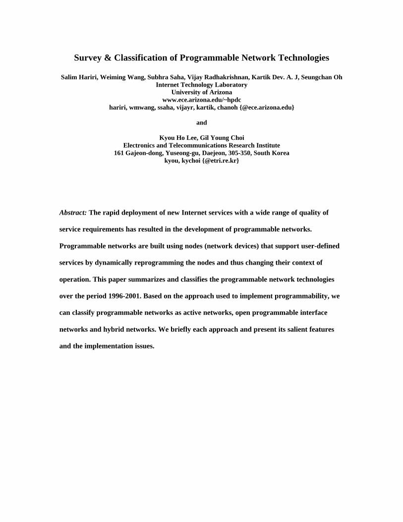
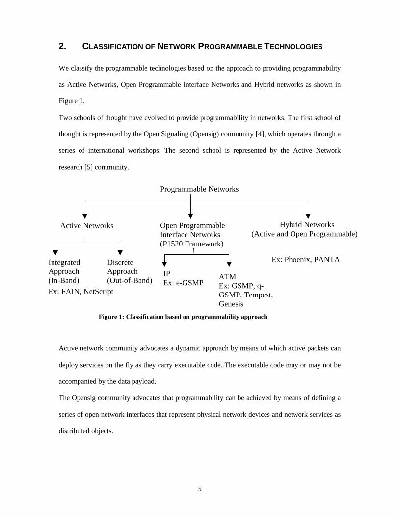
2. CLASSIFICATION OF NETWORK PROGRAMMABLE TECHNOLOGIES
We classify the programmable technologies based on the approach to providing programmability
as Active Networks, Open Programmable Interface Networks and Hybrid networks as shown in
Figure 1.
Two schools of thought have evolved to provide programmability in networks. The first school of
thought is represented by the Open Signaling (Opensig) community [4], which operates through a
series of international workshops. The second school is represented by the Active Network
research [5] community.
Active network community advocates a dynamic approach by means of which active packets can
deploy services on the fly as they carry executable code. The executable code may or may not be
accompanied by the data payload.
The Opensig community advocates that programmability can be achieved by means of defining a
series of open network interfaces that represent physical network devices and network services as
distributed objects.
Programmable Networks
Active Networks Open ProgrammableInterface Networks(P1520 Framework)
IntegratedApproach(In-Band)
DiscreteApproach(Out-of-Band)
Hybrid Networks(Active and Open Programmable)
Figure 1: Classification based on programmability approach
IPEx: e-GSMP
ATMEx: GSMP, q-GSMP, Tempest,Genesis
Ex: Phoenix, PANTA
Ex: FAIN, NetScript
6
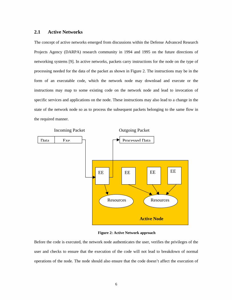
2.1 Active Networks
The concept of active networks emerged from discussions within the Defense Advanced Research
Projects Agency (DARPA) research community in 1994 and 1995 on the future directions of
networking systems [9]. In active networks, packets carry instructions for the node on the type of
processing needed for the data of the packet as shown in Figure 2. The instructions may be in the
form of an executable code, which the network node may download and execute or the
instructions may map to some existing code on the network node and lead to invocation of
specific services and applications on the node. These instructions may also lead to a change in the
state of the network node so as to process the subsequent packets belonging to the same flow in
the required manner.
Before the code is executed, the network node authenticates the user, verifies the privileges of the
user and checks to ensure that the execution of the code will not lead to breakdown of normal
operations of the node. The node should also ensure that the code doesn’t affect the execution of
Figure 2: Active Network approach
EE
EE
EE
Active Node
Resources
EE
Resources
Data Exe. Processed Data
Incoming Packet Outgoing Packet
7
other processes running on the node. The nodes that support execution of downloadable code are
referred to as active nodes. Thus active nodes are able to perform more complex functions than
the traditional nodes. The packets containing the instructions are sometimes referred to as mobile
agents. Mobile agents trigger adaptation of applications inside the network on behalf of the users
at a remote node [8].
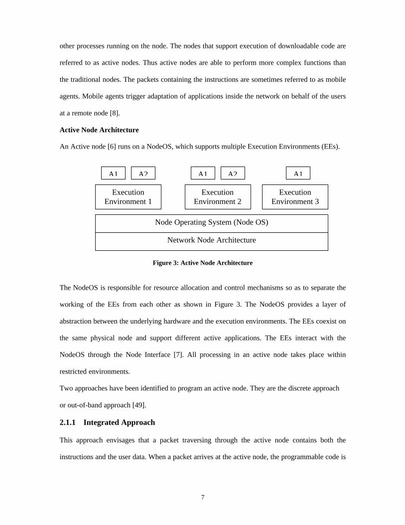
Active Node Architecture
An Active node [6] runs on a NodeOS, which supports multiple Execution Environments (EEs).
Figure 3: Active Node Architecture
The NodeOS is responsible for resource allocation and control mechanisms so as to separate the
working of the EEs from each other as shown in Figure 3. The NodeOS provides a layer of
abstraction between the underlying hardware and the execution environments. The EEs coexist on
the same physical node and support different active applications. The EEs interact with the
NodeOS through the Node Interface [7]. All processing in an active node takes place within
restricted environments.
Two approaches have been identified to program an active node. They are the discrete approach
or out-of-band approach [49].
2.1.1 Integrated Approach
This approach envisages that a packet traversing through the active node contains both the
instructions and the user data. When a packet arrives at the active node, the programmable code is
A1 A2 A1 A2 A1
ExecutionEnvironment 1
ExecutionEnvironment 2
ExecutionEnvironment 3
Node Operating System (Node OS)
Network Node Architecture
8
evaluated and built-in primitives or functions or execution environments are invoked. The
execution environment then acts upon the user data.
2.1.2 Discrete approach
This approach is based on the principle that the users can first inject their custom processing
routines into the network nodes and then send their data packets. The node is configured by the
instructions in the first packet to perform the required operations on the subsequent packets. The
processing of the subsequent packets is linked to the instructions in the first packet.
Applications of active networks includes network congestion control, downloadable diagnostic
functionality for network management and intelligent packets that can find the most effective
route under a given network condition.
Challenges in supporting active networks include identification of the source network element
and the user, verification of the authorization for the access of the various node resources and
execution based on the authorization, ensuring that current services are unaffected by the
invocation of a new services and processing packets and implementing instructions to meet real
time demands.
Of the various implementations of active network technologies studied, we would like to briefly
discuss the FAIN project and the NetScript implementation.
FAIN [12] proposes to provide programmability in an IP environment primarily through active
packets processed by active nodes. The active nodes are built by transforming the traditional
network nodes by addition of computational power and suitable interfaces. The OS of the
traditional nodes is enhanced to support programmability related needs. FAIN also envisages the
usage of programmable interfaces to configure and manage the active nodes. But the essential
function of providing programmability to support user applications and services is provided by
the execution environments. The active packets carry the instructions for the invocation of
execution environments at the node. Multiple instances of the execution environment, each
9
differing from the other, may exist at the same time. The active node platform ensures fair
allocation resources among competing execution environments. The properties of the execution
environments may differ from one another. They could be invoked either during the node
initialization or later on arrival of a specific request through the active packets. Only the network
administrator can control active nodes through open programmable interfaces for network
management. Further implementation details are in section 3.1.
NetScript [41] is an approach to provide programmability at the intermediate nodes in the
network through the deployment of software on a dynamic basis. The installation of software that
needs to be installed at the intermediate node is performed through agents that are transmitted
from the end nodes to the intermediate nodes.
In the NetScript architecture the network is considered as a collection of Virtual Network Engines
(VNE) interconnected by Virtual Links (VL). The agents traverse through the virtual links and
are executed at the VNEs. The service layer at the VNE allows multi-threaded execution of the
agents. NetScript is an example of the discrete active programmable network. The first packet
contains the information needed by the VNE to process the packets that arrive subsequently
belonging to the same stream. The subsequent packets that arrive at the VNE are identified by the
stream id to which they belong to and suitably processed as per the instructions of the first packet.
Further details are in section 3.2.
2.2 Open Programmable Interface Networks
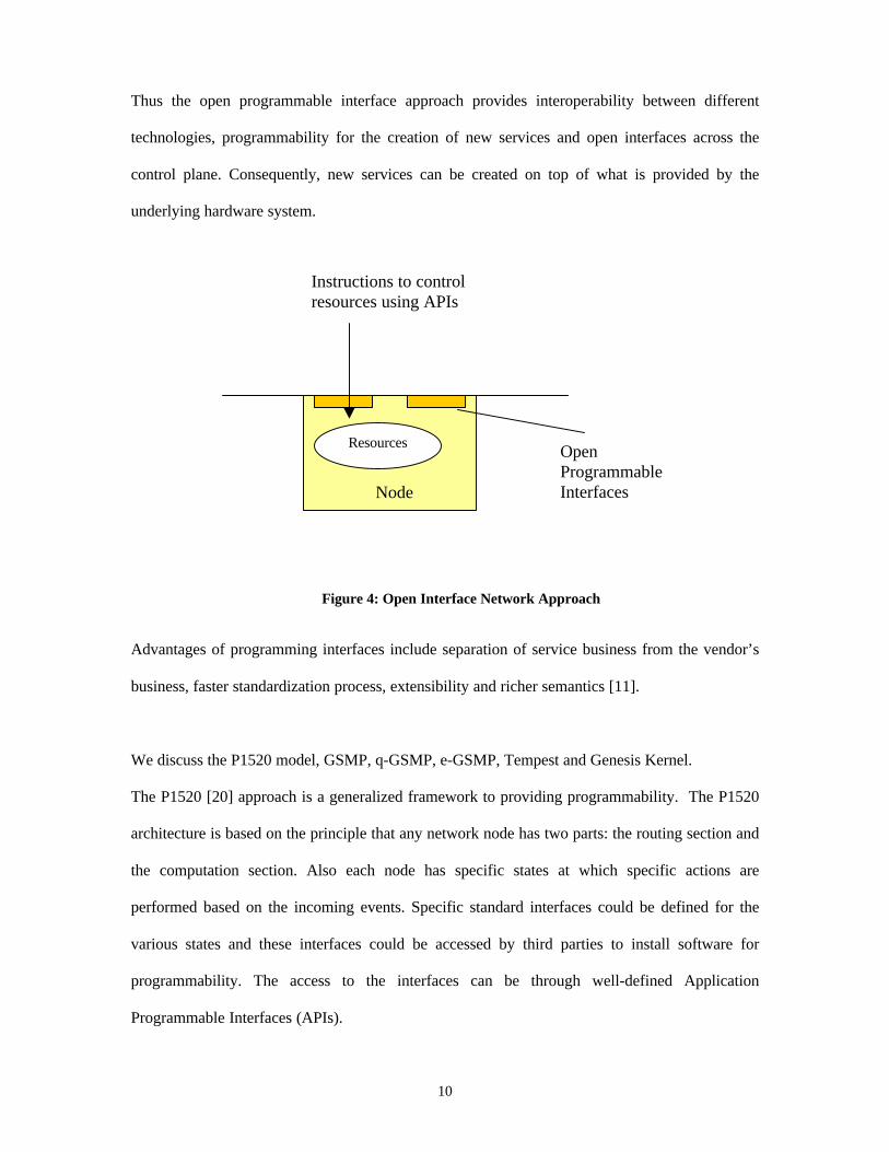
The open programmable interface network approach is based on the principle that
programmability exists in all layers of the network [10]. Each layer has entities that have finite
states. It is possible to provide software abstractions to these states that will allow third parties to
access the state information and manipulate this information through programming interfaces as
shown in Figure 4. Algorithms for signaling and control may access the state information.
10
Thus the open programmable interface approach provides interoperability between different
technologies, programmability for the creation of new services and open interfaces across the
control plane. Consequently, new services can be created on top of what is provided by the
underlying hardware system.
Advantages of programming interfaces include separation of service business from the vendor’s
business, faster standardization process, extensibility and richer semantics [11].
We discuss the P1520 model, GSMP, q-GSMP, e-GSMP, Tempest and Genesis Kernel.
The P1520 [20] approach is a generalized framework to providing programmability. The P1520
architecture is based on the principle that any network node has two parts: the routing section and
the computation section. Also each node has specific states at which specific actions are
performed based on the incoming events. Specific standard interfaces could be defined for the
various states and these interfaces could be accessed by third parties to install software for
programmability. The access to the interfaces can be through well-defined Application
Programmable Interfaces (APIs).
Figure 4: Open Interface Network Approach
Node
ResourcesOpenProgrammableInterfaces
Instructions to controlresources using APIs
11
The P1520 provides a general model for mapping the interfaces and functions over any given
network technology. The actual implementation details and protocol specific details are left to the
vendor to decide. This approach separates the protocol development from the internal
functionality thus providing faster and flexible software development. Details of this approach are
in section 3.3.
In GSMP [26], q-GSMP [31] and e-GSMP the relationship between the host controller and the
switches/routers is that of master-slave. Well-defined messages are used to communicate between
the master and the slaves through open programmable interfaces. The master can configure and
monitor the working of the slaves. The slaves inform the master of the status of the various
resources in the switch and inform any exceptions or errors. This approach is limited to
controlling the switches in the same domain or area as that of the master. Further details are in
sections 3.4, 3.5 and 3.6.
Tempest [45] is based on the concept of providing programmability through virtual networks.
Virtual networks are established by providing an interconnection between the multiple control
entities that exist on the physical switches. The physical resources of the switch are divided
among the control entities in such a way as to support negligible interference between the control
entities. Tempest supports only out of band programmability for the control entities. Details are in
section 3.7.
Genesis Kernel [33] is based on the concept of dynamically creating virtual networks to enable
deployment of specialized services in the network through distributed object architecture. The
network objects are programmable through external controllers. A parent-child relationship exists
between the parent and the spawned virtual network. The physical resources at the network node
are physically divided between the parent and child network nodes. However, to enable dynamic
programming, the resources are not shared between the parent and the spawned child networks.
Processes manage the node resources. These processes exist for both the parent and the child
12
networks. A programmable interface is provided to allow the programming of the node
resources. Details are in section 3.8.
2.3 Hybrid Networks
The hybrid network approach to provide programmability in the network encompasses both the
active and the open interface programmable approaches. The type of approach implemented
depends on the type of service to be provided.
We would briefly discuss the Phoenix framework and the PANTA approaches which fall under
this category.
The Phoenix framework [17] uses both the active network approach and the open programmable
interface approach to achieve network programmability. The network nodes are provided with
programmable interfaces for easy programmability by the user. Mobile agents are used to provide
services and extra computation at the remote nodes. The ability to launch mobile agents and
provide programmable agents is restricted to a few networks designated as the active nodes.
These nodes are used to coordinate the establishment of network services across nodes, which are
not programmable. A set of basic services is supported at the network nodes. Specialized services
are built using the set of basic services as per the instructions in the agent. Authentication and
resource allocation and usage of the mobile agents are performed at the network active nodes.
Data regarding the performance and the system requirements of the adjacent network nodes is
maintained at the active node. Upon arrival of a mobile agent requesting an appropriate from a
particular node, the availability of the remote node and its present resource status is verified by
the active node before proceeding to initiate a new network service at the remote node. The
details are in section 3.9.
The PANTA [38] implementation is based on the splitting of an existing connection at the
transport layer. The split point forms a joint between the two communication paths. The process
13
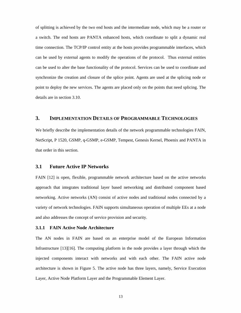
of splitting is achieved by the two end hosts and the intermediate node, which may be a router or
a switch. The end hosts are PANTA enhanced hosts, which coordinate to split a dynamic real
time connection. The TCP/IP control entity at the hosts provides programmable interfaces, which
can be used by external agents to modify the operations of the protocol. Thus external entities
can be used to alter the base functionality of the protocol. Services can be used to coordinate and
synchronize the creation and closure of the splice point. Agents are used at the splicing node or
point to deploy the new services. The agents are placed only on the points that need splicing. The
details are in section 3.10.
3. IMPLEMENTATION DETAILS OF PROGRAMMABLE TECHNOLOGIES
We briefly describe the implementation details of the network programmable technologies FAIN,
NetScript, P 1520, GSMP, q-GSMP, e-GSMP, Tempest, Genesis Kernel, Phoenix and PANTA in
that order in this section.
3.1 Future Active IP Networks
FAIN [12] is open, flexible, programmable network architecture based on the active networks
approach that integrates traditional layer based networking and distributed component based
networking. Active networks (AN) consist of active nodes and traditional nodes connected by a
variety of network technologies. FAIN supports simultaneous operation of multiple EEs at a node
and also addresses the concept of service provision and security.
3.1.1 FAIN Active Node Architecture
The AN nodes in FAIN are based on an enterprise model of the European Information
Infrastructure [13][16]. The computing platform in the node provides a layer through which the
injected components interact with networks and with each other. The FAIN active node
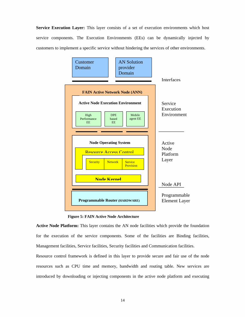
architecture is shown in Figure 5. The active node has three layers, namely, Service Execution
Layer, Active Node Platform Layer and the Programmable Element Layer.
14
Service Execution Layer: This layer consists of a set of execution environments which host
service components. The Execution Environments (EEs) can be dynamically injected by
customers to implement a specific service without hindering the services of other environments.
Active Node Platform: This layer contains the AN node facilities which provide the foundation
for the execution of the service components. Some of the facilities are Binding facilities,
Management facilities, Service facilities, Security facilities and Communication facilities.
Resource control framework is defined in this layer to provide secure and fair use of the node
resources such as CPU time and memory, bandwidth and routing table. New services are
introduced by downloading or injecting components in the active node platform and executing
HighPerformance
EE
DPEbased
EE
Mobileagent EE
Node Kernel
Security
CustomerDomain
AN SolutionproviderDomain
ServiceExecutionEnvironment
ActiveNodePlatformLayer
ProgrammableElement Layer
Interfaces
Network ServiceProvision
Node Operating System
Active Node Execution Environment
Programmable Router (HARDWARE)
FAIN Active Network Node (ANN)
Figure 5: FAIN Active Node Architecture
Node API
Resource Access Control
15
them in the EEs. These components can be remotely controlled or dynamically programmed for
easy customization.
3.1.2 FAIN Network Management
• Policy based Active Network Management: It provides programmable network
configuration, efficient network error detection and dynamic resource management
through continuous interaction between the active nodes. Policies are defined for the
allocation of the resources to the various applications.
• Dynamic Creation of Protocols: It provides rapid provision and update of protocol
stacks by injecting application specific code into the active node to provide application
specific network services.
The FAIN approach doesn’t address the issue of interaction of the active nodes with non-active
nodes. Also the functions and the implementation details of mobile agents need further
explanation.
3.2 NetScript Architecture
In NetScript the active programmability approach is implemented in middleware. The Netscript
model assumes the network to consist of Virtual Network Engines (VNE), which are
interconnected by Virtual Links (VL). A VL may be a collection of multiple physical links.
Multiple instances of VNEs may exist in one physical node. The VNEs and VLs collectively form
the NetScript Virtual Network (NVN). NetScript agents program the VNEs over the VLs.
A virtual network programmed in NetScript consists of agents that configure and maintain the
virtual network topology and resources, agents that provide routing and flow control functions
along the virtual links of this network and agents that support signaling protocols for this virtual
network.
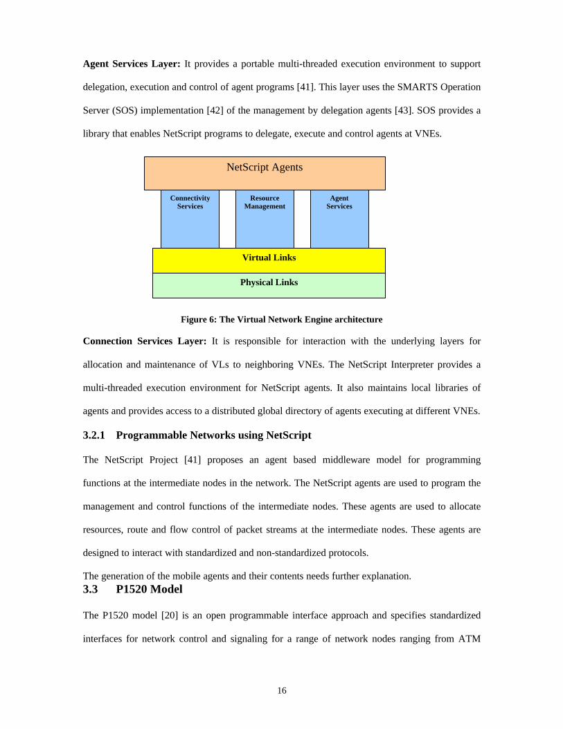
Virtual Network Engine: The NetScript agents are supported by the Connectivity services,
Resource Management and Agent Services layers. Figure 6 illustrates the VNE architecture.
16
Agent Services Layer: It provides a portable multi-threaded execution environment to support
delegation, execution and control of agent programs [41]. This layer uses the SMARTS Operation
Server (SOS) implementation [42] of the management by delegation agents [43]. SOS provides a
library that enables NetScript programs to delegate, execute and control agents at VNEs.
Figure 6: The Virtual Network Engine architecture
Connection Services Layer: It is responsible for interaction with the underlying layers for
allocation and maintenance of VLs to neighboring VNEs. The NetScript Interpreter provides a
multi-threaded execution environment for NetScript agents. It also maintains local libraries of
agents and provides access to a distributed global directory of agents executing at different VNEs.
3.2.1 Programmable Networks using NetScript
The NetScript Project [41] proposes an agent based middleware model for programming
functions at the intermediate nodes in the network. The NetScript agents are used to program the
management and control functions of the intermediate nodes. These agents are used to allocate
resources, route and flow control of packet streams at the intermediate nodes. These agents are
designed to interact with standardized and non-standardized protocols.
The generation of the mobile agents and their contents needs further explanation.3.3 P1520 Model
The P1520 model [20] is an open programmable interface approach and specifies standardized
interfaces for network control and signaling for a range of network nodes ranging from ATM
Physical Links
Virtual Links
ConnectivityServices
ResourceManagement
AgentServices
NetScript Agents
17
switches to IP routers. The P1520 is based on the principle of dissociating the maintenance of
state information from the algorithms that manipulate state in a network. The P1520 model only
defines the interfaces leaving the algorithms and the protocols needed for the implementation to
the vendor. The interfaces are structured in layers and each layer provides services to the layer
above. Each layer contains a number of entities, which may be either algorithms or objects. These
entities represent logical or physical resources depending on the level’s scope and functionality.
3.3.1 The P1520 Architecture
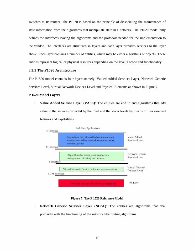
The P1520 model contains four layers namely, Valued Added Services Layer, Network Generic
Services Level, Virtual Network Devices Level and Physical Elements as shown in Figure 7.
P 1520 Model Layers
• Value Added Service Layer (VASL): The entities are end to end algorithms that add
value to the services provided by the third and the lower levels by means of user oriented
features and capabilities.
Figure 7: The P 1520 Reference Model
• Network Generic Services Layer (NGSL): The entities are algorithms that deal
primarily with the functioning of the network like routing algorithms.
18
• Virtual Network Device Layer (VNDL): At VNDL, the entities are the logical
representations of certain state variables of these entities in the first level.
• Physical Elements Layer (PE): The entities in the PE layer are the physical entities like
routers and switches.
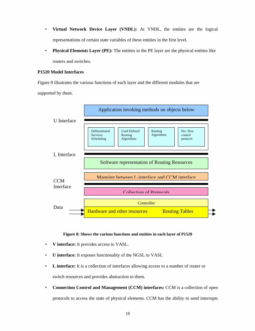
P1520 Model Interfaces
Figure 8 illustrates the various functions of each layer and the different modules that are
supported by them.
Figure 8: Shows the various functions and entities in each layer of P1520
• V interface: It provides access to VASL.
• U interface: It exposes functionality of the NGSL to VASL
• L interface: It is a collection of interfaces allowing access to a number of router or
switch resources and provides abstraction to them.
• Connection Control and Management (CCM) interfaces: CCM is a collection of open
protocols to access the state of physical elements. CCM has the ability to send interrupts
Application invoking methods on objects below
DifferentiatedServicesScheduling
Used DefinedRoutingAlgorithms
RoutingAlgorithms
Per- flowcontrolprotocol
Software representation of Routing Resources
Mapping between L-interface and CCM interface
Collection of Protocols
Hardware and other resources Routing Tables
U Interface
L Interface
CCMInterface
DataController
19
to the higher layers indicating occurrence of events such as flow identification and other
exceptions.
Implementing P1520 oriented towards providing per-flow customized QoS (QoS-aware inter-
working solution and service) treatment requires the node to support management of the (binding
of) scheduling of ATM services, management of the processing resources of an IP switch and
customization of per-flow processing or application-activated QOS processing in addition to its
traditional function of routing.
The difficulties for the P1520 Model to abstract the IP routers are:
• Too many functions need to be described. These include functions for Forwarding,
Connection, Line and Port Control, Route Control (Routing table, Forward Policy) and
Traffic Control.
• Many control functions should be fulfilled both at the layer of CCM and L-interface such
as routing table maintenance. This violates the layered approach architecture.
3.4 General Switch Management Protocol (GSMP)
General switch management protocol is a protocol for the management of an ATM switch [26]
and is an open programmable interface approach. It is based on the concept of Master-Slave
control. The master is the controller, which is an external device controlling one or more ATM
switches and is programmable by the user. The controller is responsible for the initial
configuration of the ATM switches or the slaves, establishment and release of connections across
the switches, addition or deletion of nodes on a point-to-multipoint connection and the
management of switch ports. The switches are responsible for sending the status of their links and
statistics to the controller. The occurrence of events, such as links going down, are reported by
the switch to the controller.
The ATM switch is regarded as containing ‘ports’. The port number may reflect the physical
location of the port on the switch. Each port consists of an input and an output port. Cells arrive
on a VCC on a port. An association of the virtual channels and virtual path identifiers forms
20
virtual channels. Virtual connections are referenced by the input port on which they arrive and the
virtual channel and path identifiers. Each port maintains a port session number assigned by the
port. The programmability is achieved by the control of the switch resources through the
controller. The controller issues request messages to the slaves. Each request message indicates if
a response is required from the switch and also if a transaction identifier is required to enable the
request to be identified with the response. The slave may respond with success or failure after the
action requested was performed by the switch.
The GSMP messages are grouped into four distinct categories, namely, Connection Management,
Port Management, Statistics, Configuration, Event and Adjacency protocol messages [26]. Each
of these messages contains the version number of the protocol, the message type and result field,
which indicates if a response, is required from the switch.
The GSMP was designed to manage the functions of an ATM switch through an external
controller. Though it allows for the control of the various connections, it lacks the ability to
control the queues and the scheduling mechanisms in order to provide deterministic QoS. It
addresses this issue by assigning priorities to each virtual connection when established. For
virtual channel connections that share the same output port, an ATM cell belonging to a
connection having a higher priority is given preference over lower priority connection. This is
inadequate in view of the different classes of network traffic.
3.5 q-General Switch Management Protocol (q-GSMP)
Quality of Service extensions to the GSMP is specified by q-GSMP [31]. It provides a means to
control the scheduler, buffer management and schedulable regions. The q-GSMP messages can be
classified into the same five classes as of GSMP but with a difference. The left most bits in the
message type field are set to one for QoS extension messages. Thus the q-GSMP messages are
backward compatible with the GSMP messages. Bit masks are used to identify buffers, traffic
classes and QoS parameters.

21
The QoS configuration messages have new fields, which allow the controller to query the
scheduling and buffer management policies, schedulable region estimation algorithms and traffic
class characteristics supported by the switch. Traffic characterization into video, voice and data is
supported. QoS parameters like maximum delay, average delay, probability of loss, maximum
gap loss, peak rate and average rate are supported. Various scheduling algorithms like first-in-
first-out, weighted round robin, static priority scheduling and MARS [32] are supported. Buffer
management includes support of a simple policy and threshold policy. Various memory allocation
schemes and memory sizes are also supported.
Thus q-GSMP connection management messages allow the setting up of different types of traffic
classes, number of buffers for each class and scheduling policies for each class of traffic. Statistic
messages allow the controller to query the switch on the QoS measurements and schedulable
region estimates.
The controller is alerted to the various QoS related changes in the switch by the QoS Event
messages. Thus q-GSMP provides a means to control the QoS features for an ATM switch.
GSMP and q-GSMP provide a means to program a group of switches or routers and thus can’t be
used for launching services at remote nodes in other networks. Also they are suitable only for
ATM.
3.6 Enhanced General Switch Management Protocol (e-GSMP)
e-GSMP aims to provide QoS services primarily over an IP network. The framework for the
development of this protocol is on the lines of the GSMP and the q-GSMP.
e-GSMP defines two types of entities namely, the e-GSMP Master and the e-GSMP Slave. The e-
GSMP Master is the host application, which interacts with the e-GSMP slaves and the end user
through a set of well-defined e-GSMP messages. The e-GSMP slaves are the network nodes, may
be routers or switches, which actually process the packets. Each e-GSMP slave may be connected
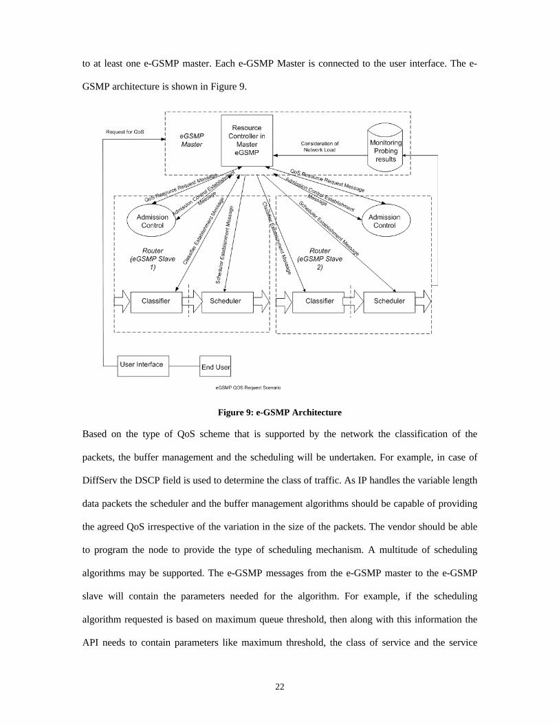
22
to at least one e-GSMP master. Each e-GSMP Master is connected to the user interface. The e-
GSMP architecture is shown in Figure 9.
Figure 9: e-GSMP Architecture
Based on the type of QoS scheme that is supported by the network the classification of the
packets, the buffer management and the scheduling will be undertaken. For example, in case of
DiffServ the DSCP field is used to determine the class of traffic. As IP handles the variable length
data packets the scheduler and the buffer management algorithms should be capable of providing
the agreed QoS irrespective of the variation in the size of the packets. The vendor should be able
to program the node to provide the type of scheduling mechanism. A multitude of scheduling
algorithms may be supported. The e-GSMP messages from the e-GSMP master to the e-GSMP
slave will contain the parameters needed for the algorithm. For example, if the scheduling
algorithm requested is based on maximum queue threshold, then along with this information the
API needs to contain parameters like maximum threshold, the class of service and the service

23
rate. This allows greater flexibility, as algorithms for scheduler and buffer management will be
independent of each other and can be programmed by the user.
The e-GSMP master can request for the status of the various resources from the e-GSMP slaves.
This information when obtained from the e-GSMP slaves can be sent by the e-GSMP master to
the vendor. The GSMP messages will be modified to incorporate sub-fields for indication of type
of QoS framework, namely, DiffServ or IntServ. The identification of the messages as that of e-
GSMP will be based on the version number.
e-GSMP can’t be used to implement services at a remote node not belonging to the subnet or area
to which the controller belongs.
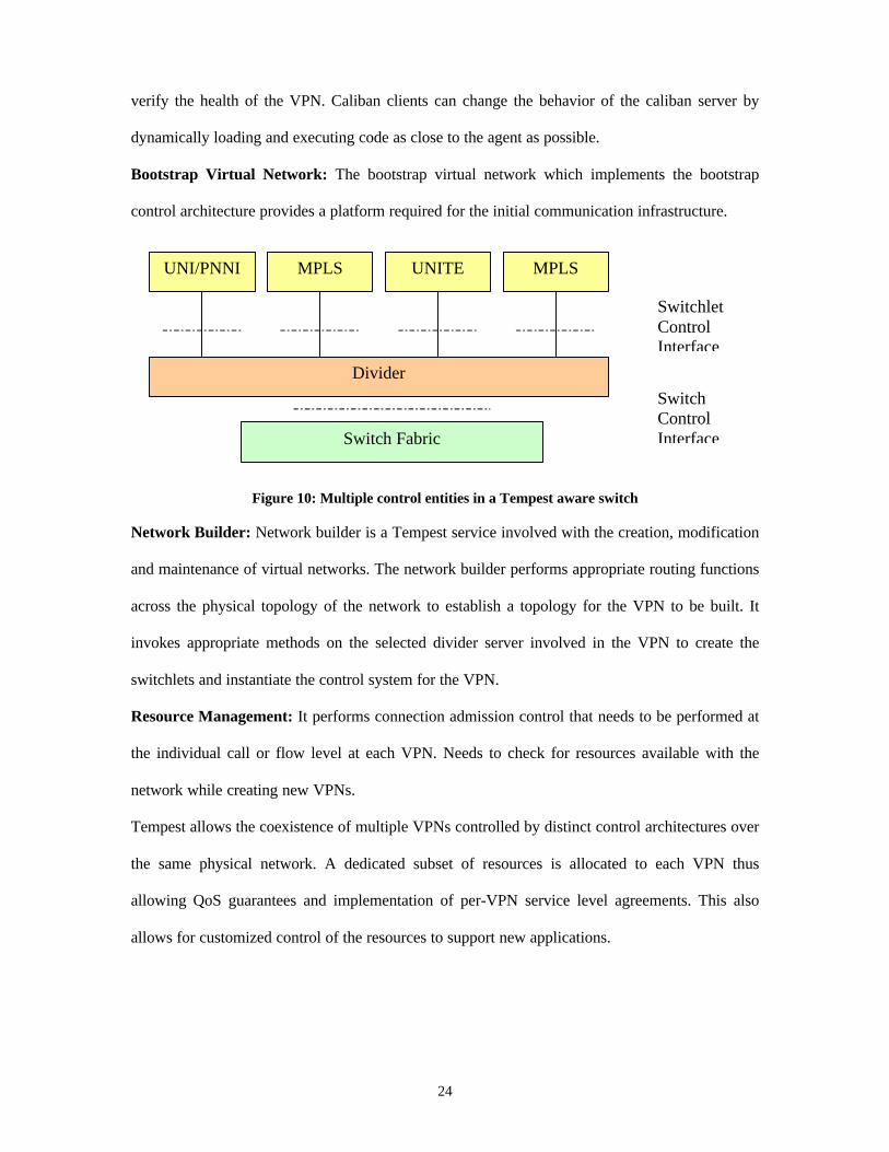
3.7 Tempest
Tempest provides a framework in which virtual private networks can be dynamically created and
assigned a dedicated set of network resources at each network node as shown is Figure 10. This
ensures formation of resource assured VPNs. The Tempest model has been implemented on an
ATM switch but can also be implemented in the IP routers and is an open programmable interface
approach. The Tempest model allows several control entities to simultaneously control partitions
of the physical switch resources.
3.7.1 The Tempest Building Blocks
Prospero Switch Divider: The prospero switch divider performs the partitioning of the physical
switch resources between the control architectures into switchlets. It’s the divider’s prerogative to
ensure that the control entities use only the resources allocated to them. The switchlet resources
are made available to the control entities by means of the Ariel Switchlet Control Interface.
Ariel Switch Independent Control Interface: The Ariel server translates the Ariel control
operations into a form understood by the physical switch. Ariel uses the QoS parameters to allow
control architectures to specify the resources that need to be associated with a connection.
The Caliban Switch Management Interface: Caliban provides an interface that maps a set of
primitives to a variety of underlying management protocols allowing the network administrator to
24
verify the health of the VPN. Caliban clients can change the behavior of the caliban server by
dynamically loading and executing code as close to the agent as possible.
Bootstrap Virtual Network: The bootstrap virtual network which implements the bootstrap
control architecture provides a platform required for the initial communication infrastructure.
Figure 10: Multiple control entities in a Tempest aware switch
Network Builder: Network builder is a Tempest service involved with the creation, modification
and maintenance of virtual networks. The network builder performs appropriate routing functions
across the physical topology of the network to establish a topology for the VPN to be built. It
invokes appropriate methods on the selected divider server involved in the VPN to create the
switchlets and instantiate the control system for the VPN.
Resource Management: It performs connection admission control that needs to be performed at
the individual call or flow level at each VPN. Needs to check for resources available with the
network while creating new VPNs.
Tempest allows the coexistence of multiple VPNs controlled by distinct control architectures over
the same physical network. A dedicated subset of resources is allocated to each VPN thus
allowing QoS guarantees and implementation of per-VPN service level agreements. This also
allows for customized control of the resources to support new applications.
UNI/PNNI
Divider
Switch Fabric
MPLS UNITE MPLS
SwitchletControlInterface
SwitchControlInterface
25
3.8 The Genesis Kernel
The Genesis Kernel automates the creation, deployment and management of network resources.
The Genesis kernel describes a virtual network kernel capable of profiling, spawning and
managing programmable virtual network architectures [32] and is an open programmable
network interface approach. It has the capability to spawn child network architectures, which
support signaling protocols, communication services, QoS and network management that are
different from those supported in the parent network. There is no resource sharing between the
parent and the child networks.
3.8.1 Architecture
The Genesis Kernel supports virtual network life cycle processes by allocating resources to the
child networks [33]. It is based on the principle of separation, nesting and inheritance. The
communication hardware and the network resources are abstracted and represented as a set of
distributed network objects that can be programmed by controllers to meet the demands of the
virtual network architectures.
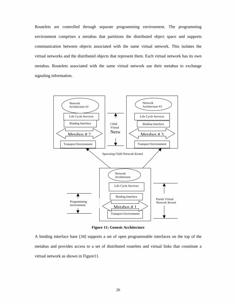
The Genesis Kernel is composed of a Transport Environment, Programming Environment and a
Life Cycle Environment as shown in Figure 11.
Transport Environment: It is a set of transport modules that deliver packets from the source to
the destination end-systems through a set of open programmable virtual router nodes called
routelets. A virtual network is characterized by a set of routelets interconnected by a set of virtual
links. The routelets and the virtual links collectively form a virtual network topology. The control
algorithms are programmed using the virtual network kernel. Routelets process packets along a
programmable data path and use the router computation and communication resources.
A routelet is managed by a control unit, which consists of a spawning controller, a composition
controller, an allocation controller and a data path controller.
Programming Environment: Child routelets are instantiated by the parent virtual network
during spawning and use a subset of the parent’s resources but work independent of the parent.
26
Routelets are controlled through separate programming environment. The programming
environment comprises a metabus that partitions the distributed object space and supports
communication between objects associated with the same virtual network. This isolates the
virtual networks and the distributed objects that represent them. Each virtual network has its own
metabus. Routelets associated with the same virtual network use their metabus to exchange
signaling information.
Figure 11: Genesis Architecture
A binding interface base [34] supports a set of open programmable interfaces on the top of the
metabus and provides access to a set of distributed routelets and virtual links that constitute a
virtual network as shown in Figure11.
Transport Environment
Metabus # 2
Binding Interface
Base
Life Cycle Services
NetworkArchitecture #2
Transport Environment
Metabus # 1
Binding Interface
Life Cycle Services
NetworkArchitecture
Transport Environment
Metabus # 3
Binding Interface
Life Cycle Services
NetworkArchitecture #3
Spawning Child Network Kernel
Parent VirtualNetwork KernelProgramming
environment
ChildVirtual
Netw
27
Every routelet is controlled through a number of implementation dependent system calls. The
binding interface base objects wrap these system calls with open programmable interfaces that
facilitate the interoperability between routelets implemented with different technologies.
Life Cycle Environment: The Genesis architecture dynamically creates and deploys virtual
network architectures through a process of profiling, spawning and management.
Profiling captures addressing, routing, signaling, security, control and management requirements
in an executable profiling script to automate the deployment of programmable virtual networks.
Spawning systematically sets up the topology and address space, allocates resources and binds
transport, routing and network management objects to the physical network infrastructure.
Management supports virtual network resource management based on per-virtual network policy
to exert control over multiple spawned network architectures.
There is always a limitation on the number of VPNs that can be supported over a physical
network. This issue needs to be addressed in Genesis Kernel.
3.9 The Phoenix Framework
The Phoenix framework is an object-oriented, distributed and security aware hybrid
programmable network framework that allows easy control and deployment of new network
services [17]. It defines an extensible mobile agent system and a set of open, safe-Java based
interfaces to provide device functionality abstractions. The mobile agent system provides a
flexible execution environment by proving access to the system resources to the mobile agents.
The Phoenix framework consists of two broad elements namely a programmable network
framework and a mobile agent system.
3.9.1 Programmable Network Framework
Network nodes supporting the Phoenix framework are called active devices. Each active device
contains a proactive console, a proactive environment and proactive services.
28
The Proactive Console: Agents and services are managed by a proactive console. The proactive
console is used by the network programmers to install new services on the devices. Each active
device hosts a proactive environment built on a Java Virtual machine (JVN) that provides basic
primitives for programming and managing the device. The proactive console contains the security
and management policy databases for the Phoenix framework.
The Proactive Environment: Management, transport and execution of mobile agents on the
active devices are the functions of the proactive environment. It is a singleton Java object on an
active device that provides a set of well-defined Java interfaces for the manipulation and
management of the active devices. Proactive services are Java objects with well-defined
interfaces and can be installed at runtime. The interfaces provided by the proactive environment
may be invoked remotely by using the Java Remote Method Invocation.
Proactive Services: Proactive services are objects that expose one or more interfaces that allow
the device functionality to be affected by mobile agents. All core proactive services are
instantiated when the proactive environment is created. The agents must have appropriate
permissions to access and use the services.
Proactive Device Object (PDO): Every network device is represented by a proactive device
object, which is a repository of information needed by the proactive environment to manage the
device. A PDO also contains the configuration data for proactive services supported by the active
device.
3.9.2 Mobile Agent
A mobile agent contains an itinerary object that determines the active devices the agent will visit
during its lifetime. It also contains a Work Object (WO), which specifies the nature of interaction
of the mobile agent with the proactive environment. Each WO contains one or more WorkSheet
(WS) objects that specify the action performed by the agent at each device. On arrival at a device,
the mobile agent is first authenticated and only after validation the WO is executed.
29
The Phoenix framework allows scripts to be executed remotely for network management in cases
where a network administrator is unable to access the node directly. It can be used to predict and
analyze congestion in a network by placing an agent nearest to the congested node to study the
traffic behavior and to detect intrusion into the network and fault diagnosis.
More details are required regarding the usage of PDO. It also doesn’t explain in detail the
mechanism for launching mobile agents.
3.10 Programmable Active Network Transport Architecture (PANTA)
PANTA is a graph oriented hybrid programmable network architecture based on the concept of
transport splicing at the transport connection level [38]. Splicing involves the segmentation of
the end-to-end connections between communication applications with the spliced point forming a
bridge between the two original communication endpoints.
The PANTA architecture consists of PANTA enhanced hosts and routers. The creation of a splice
point is coordinated between the end-to-end PANTA enhanced hosts and the intermediate splice
point router. Splicing can either occur during the connection establishment phase or during the
communication between the hosts.
Each PANTA enhanced host consists of TCP/UDP, which provides the transport mechanism for
the transfer of data. Services are implemented and invoked at the service agent level and scripting
level. The service agent level comprises of a collection of core-level agent services and user
defined agent services. Core-level agent services are used to create a splicing point, synchronize
transfer, introduce new services and accept new services. This is done by cloning of agents at the
local host and instantiating agents at the splicing points and at the destination end point. The
agents are responsible for coordinating the splicing process by creating appropriate paths between
the splice point and the end-to-end points. The services are deployed by binding the new spliced
paths to the end-to-end applications.
30
PANTA also proposes a graph oriented programming approach to model the dynamic
configuration of active networks. In this approach a collection of programming primitives can be
invoked from within a graph-oriented application for direct configuration of network structure
and functionality. A logical graph is used as an abstraction for expressing and defining the
communication and synchronization among the active nodes.
PANTA architecture may be employed to rapidly deploy a service by programming the agent
service at the user process level. It may be used to setup multicast multimedia applications. In
such cases the effects of congestion may be mitigated by using a service agent at the congested
node to perform dynamic sub-sampling of incoming packets among the affected members of the
group.
The ability of a non-PANTA enhanced nodes to support splitting needs to be addressed.
4. CONCLUSION
In this paper we surveyed and classified different approaches to implement programmable
networks. We classified the current programmable network techniques based on the network
programmability approach. An examination of the various implementations in each category
clearly indicates that though active network approach provides greater flexibility to the network
nodes, it increases the complexity of the nodes and has huge implementation overheads. The open
network interface approach provides standard application programming interfaces to third party
developers. This approach though easier to implement cannot provide flexibility comparable to
the active networks approach. Many of the programmable technologies can be classified under
multiple criteria. For example, we can classify GSMP as a technology supporting ATM and also
as an open programmable network interface with a single controller. We also briefly discussed
our approach to providing programmability in an IP network called e-GSMP, which is based on
the open programmable network interface approach. It is clear from the examination of the
programmable technologies that there is no one technology or model that is the superior to all the
other technologies. Approaches and implementations vary based on the necessity and complexity
31
of the issues that must be addressed by the programmable technologies. We are currently working
on identifying the research issues associated with each of the programmable network approaches.
5. REFERENCES
[1] J. Biswas et al., “ The IEEE P1520 Standards Initiative for Programmable NetworkInterfaces”, IEEE Communications magazine, October 1998, pp. 64-70
[2] D. Wetherall et al., “Introducing New Internet Services: Why and How”, IEEE Network,May/June 1998, pp. 12-19
[3] R. Kawamura, R. Stadler, “ A Middleware Architecture for Active Distributed Managementof IP Networks”, IEEE 2000
[4] D.J. Wetherall, J. Gutter, D. Tennenhouse- “ANTS A toolkit for building and dynamicallydeploying network protocol” IEEE OPENARCH, April 1998
[5] D. Tennenhouse, D. Wetherall –“Towards an active network architecture” ComputerCommunications Review, 26, 2 (1996), pp 5-18
[6] Calvert, K.L., ed. “Architectural Framework for Active Networks”, Version 1.0, ActiveNetwork Working Group, July 1999
[7] AN Node OS Working Group, “NodeOS Interface Specification”, January 2000.
[8] Hermann De Meer, Aurelio La Corte, Antonio Puliafito, Orazio Tomarchio, “ ProgrammableAgents for Flexible QoS Management in IP Networks”, IEEE Journal on slected areas incommunication, Vol. 18, No.2, February 2000
[9] David L. Tennenhouse, Jonathan M. Smith, W. David Sincoskie, David J. Wetherall, Gray J.Minden, “A survey of Active Network Research”, IEEE Communications Magazine, January1997
[10] Biswas, J., Lazar, A. A., Huard J.F., Lim, K., Mahjoub S., Pau L.-F., Suzuki, M.,Torstensson S., Wang W. and Weinstein S. “The IEEE P1520 Standards Initiative forProgrammable Network Interfaces”, IEEE Communications Magazine, Vol. 36, No. 10, October1998, pp. 64-70
[11] Biswas, J., Pierre Lin, Spyros Denazi, John Vicente, Masaaki Suzuki, Jens-Peter Redlich,Fernando Cuervo, Jit Biswas, Weiguo Wang, Kazuho Miki, Jairo Gutierrez, “ProgrammingInterfaces for IP Networks- A white paper”. P1520/T/IP-001
[12] Alex Galis, Bernhard Plattner, Jonathan M. Smith, Spyros Deazis, Eckhard Moeller, HuiGuo, Cornel Klein, Joan Serrat, Jan Laarhuis, George T. Karetsos and Chris Todd, “A Flexible IPActive Networks Architecture”
[13] Report of the Sixth Strategic Review Committee on European Information Infrustructure-www.etsi.org/specrec/SRC6/SRC6.htm
[14] IETF “An architecture for Differentiated Services” S. Blake, August 1998
32
[15] DARPA Active Networks Program. www.ito.darpa.mil.research/anets
[16] A. Galis, B. Plattner, J.M. Smith, S. Denazis, H. Guo, C. Klein, J. Serrat, J. Laarhuis, G.T.Karetsos, C. Todd “A Flexible IP Active Networks Architecture” in the Proceedings SecondInternational Working Conference, IWAN’2000-Japan, October 2000, ISBN 3-540-41179-8,Springe
[17] David Putzolu, Sanjay Bakshi, Satyendra Yadav, Raj Yavatkar, Intel Corporation, “ThePhoenix Framework: A Practical Architecture for Programmable Networks”. IEEECommunications magazine, March 2000
[18] J. Hartman et al. “Joust: A platform for Liquid software”, IEEE Comp. April 1999, pp. 50-56
[19] D. Wetherall et al. “ Introducing New Internet Services: Why and How”. IEEE NetworkMay/June 1998, pp. 12-19
[20] Biswas, J., Pierre Lin, Spyros Denazi, John Vicente, Masaaki Suzuki, Jens-Peter Redlich,Fernando Cuervo, Jit Biswas, Weiguo Wang, Kazuho Miki, Jairo Gutierrez, “ProgrammingInterfaces for IP Networks- A white paper”. P1520/T/IP-001
[21] Biswas, J., “ The IEEE P1520 Standards Initiative for Programmable Network Interfaces”,IEEE Communications, Special issue on Programmable networks, Vol. 36, No 10, October 1998.http://www.ieee-pin.org
[22] J.Biswas, J-F Hurd, A. Lazar, K. Lim, A. Smahjoub, L-F. Pau, M. Suzuki, S. Torstenson,W.Weiguo, S. Weinstein – “White paper on Application Programming Interfaces for Networks,Working Group for IEEE P1520”, January 1999.
[23] IETF Internet Draft, "Provider Architecture for Differentiated Services and TrafficEngineering (PASTE)", draft-li-paste-oo.txt, January, 1998.
[24] IETF RFC22054, "Resource Reservation Protocol (RSVP) – Version 1 FunctionalSpecification", September, 1997.
[25] Lazar, A.A., Lim, K.S. and Marconcini, F., “Realising a Foundation forProgrammability of ATM Networks with the Binding Architecture”, IEEE Journalof Selected Areas in Communications, Special Issue on Distributed MultimediaSystems, Vol. 14, No. 7, September 1996.
[26] Calvert, K. L., Bhattacharjee, S., Zegura, E. and Sterbenz, J. “Directions in ActiveNetworks”, IEEE Communications Magazine, Vol 36. No. 10, October 1998, pp.72-78.
[26] RFC 1987 Ipsilon’s General Switch Management Protocol
[27] RFC 1700 “Assigned Numbers”, STD 2, RFC 1700, October 1994
[28] RFC 1573 “Evaluation of the Interfaces Group of MIB-II”, RFC 1573, January 1994
[29] I.361 “B-ISDN ATM Layer Specification”, ITU-T Recommendation , March 1993
33
[30] I.363 “B-ISDN ATM Adaptation Layer (AAL) Specification”, ITU-T RecommendationI.363
[31] Constantin M. Adam, Aurel A. Lazar, Mahesan Nandikesan, COMET Group, “QoSExtensions to GSMP”, CU/CTR/TR 471-97-05
[32] Hyman, J.M., Lazar,A.A. and Pacifici, G., “Real-Time Scheduling with Quality of ServiceConstraints”, IEEE Journal on selected Areas in Communications, Vol. 9, September 1991, pp.1052-1063
[33] A.T. Campbell, H.G. De Meer, M.E. Kounavis, J. Vicente, D.A. Villela, “The GenesisKernel: A virtual Network Operating System for Spawning Network Architectures”.
[34] Lazar, A.A., Lim, K.S and Marconcini, F. “ Realizaing a foundation for Programmability ofATM Networks with the Binding Architecture”, IEEE Journal on Selected Areas inCommunications, Special issue on Distributed Multimedia Systems, No 7, September 1996
[35] Adam, C.M, et al., “The Binding Interface Base Specification Revision 2.0”, OPENSIGWorkshop on Open Signaling for ATM, Internet and Mobile Networks, Cambridge UK, April1997
[36] Zhaung, H., and R. Treadway “Genesis Profiler Tool”, prototype software distributioncomet.Columbia.edu/genesis
[37] Cisco Systems, “Quality of Service for Virtual Private Networks”, white paper,www.cisco.com/wrap/public/779/largeent/vpne/qsvpn_wp.htm
[38] Alvin T.S.Chan, Jiannong Cao, Department of Computing, The Hong Kong PolytechnicUniversity, Hong Kong, “PANTA: A Graph-Oriented Programmable Active Network TransportArchitecture”.
[39] D. Tennenhouse and D. Wetheral, “Towards an Active Network Architecture”, ACMSIGCOMM Review, vol 26, April 1996, pp 15-18
[40] D. Tennenhouse et al. “A Survey of Active Network Research”, IEEE CommunicationsMagazine, January 1997, pp 80-86
[41] Yechiam Yemini, Sushil da Silva, Department of Computer Science, Columbia University,“Towards Programmable Networks”, April 15, 1996
[42] SMARTS, SMARTS Operational Server Manual, 1994, System Management Arts.
[43] Yemini, Y., G. Goldssmidt and S. Yemini. “Network Management by delegation” in thesecond International Symposium on International Network Management 1991, Washington DC
[44] daSilva, S. and Y. Yemini, “NetScript Language Tutorial and reference”, 1996, ColumbiaUniversity Computer Science Department, New York
34
[45] Sean Rooney, Jacobus E. van der Merwe, Simon A. Crosby and Lan M. Leslie, “TheTempest: A Framework for Safe, resource-Assured, Programmable network”,IEEECommunications Magazine, October 1998
[46] J.E.Var der Merwe et al., “The Tempest- a practical framework for networkprogrammability”, IEEE Network vol 12, May/June 1998
[47] ITU-T Recommendations I.312/Q.1201, “Principles of Intelligent Network Architectures”.1992.
[48] A.T. Campbell, H.G.De Meer, M.E. Kounavis, K. Miki, J. Vicente and D.A. Villela. “TheGenesis Kernel: A Virtual Network Operating System for Spawning Network Architectures”.1999 IEEE
[49] R. Maresca, M.D’ Arienzo, M. Esposito, S.P. Romano and G.Ventre. “An ActiveNetwork approach to QoS enabled Virtual Private Network”. April 30, 2001