Embed Size (px)
Citation preview
EUROPEAN ORGANISATION FOR THE SAFETY OF AIR NAVIGATION
E U R O C O N T R O L
EUROPEAN AIR TRAFFIC MANAGEMENT
SUR.ET2.ST03.3111-SPC-02-00
Edition : 1.3 Edition Date : January 2009 Status : Released Issue Class : General Public
EUROCONTROL STANDARD DOCUMENT
FOR
SURVEILLANCE DATA EXCHANGE
Part 5 : Category 017
Mode S Surveillance Coordination Function Messages

DOCUMENT IDENTIFICATION SHEET
DOCUMENT DESCRIPTION
Document Title Mode S Surveillance Coordination Function Messages
EWP DELIVERABLE REFERENCE NUMBER
PROGRAMME REFERENCE INDEX EDITION : 1.3
SUR.ET2.ST03.3111-SPC-02-00 EDITION DATE : January 2009
Abstract This document describes the application of ASTERIX to the transmission of Mode S Surveillance Coordination Function messages.
Keywords SCF ASTERIX Service Messages UAP Data Item Category 17
CONTACT PERSON : A. Engel TEL : +32-2-729 3355 UNIT : CND/CoE/CNS/SUR
DOCUMENT STATUS AND TYPE
STATUS CATEGORY CLASSIFICATION Working Draft � Executive Task � General Public � Draft � Specialist Task � EATCHIP � Proposed Issue � Lower Layer Task � Restricted � Released Issue �
ELECTRONIC BACKUP
INTERNAL REFERENCE NAME : HOST SYSTEM MEDIA SOFTWARE(S)
Microsoft Windows Type : Hard disk Media Identification :
Mode S Surveillance Coordination Function Messages
SUR.ET2.ST03.3111-SPC-02-00
Edition : 1.3 Released Issue Page iii
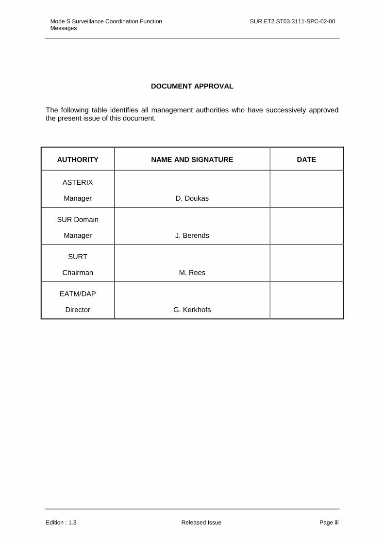
DOCUMENT APPROVAL
The following table identifies all management authorities who have successively approved the present issue of this document.
AUTHORITY NAME AND SIGNATURE DATE
ASTERIX
Manager
D. Doukas
SUR Domain
Manager
J. Berends
SURT
Chairman
M. Rees
EATM/DAP
Director
G. Kerkhofs
SUR.ET2.ST03.3111-SPC-02-00 Mode S Surveillance Coordination Function Messages
Page iv Released Issue Edition : 1.3
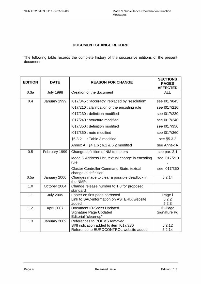
DOCUMENT CHANGE RECORD
The following table records the complete history of the successive editions of the present document.
EDITION DATE REASON FOR CHANGE SECTIONS
PAGES AFFECTED
0.3a July 1998 Creation of the document
ALL
0.4 January 1999 I017/045 : "accuracy" replaced by "resolution"
I017/210 : clarification of the encoding rule
I017/230 : definition modified
I017/240 : structure modified
I017/350 : definition modified
I017/360 : note modified
§5.3.2 : Table 3 modified
Annex A : §4.1.6 ; 6.1 & 6.2 modified
see I017/045
see I017/210
see I017/230
see I017/240
see I017/350
see I017/360
see §5.3.2
see Annex A
0.5 February 1999 Change definition of NM to meters
Mode S Address List, textual change in encoding rule
Cluster Controller Command State, textual change in definition
see par. 3.1
see I017/210 .
see I017/360
0.5a January 2000 Changes made to clear a possible deadlock in the NMP.
5.2.14
1.0 October 2004 Change release number to 1.0 for proposed standard
1.1 July 2005 Footer on first page corrected Link to SAC-information on ASTERIX website added
Page i 5.2.2 5.2.3
1.2 April 2007 Document ID-Sheet Updated Signature Page Updated Editorial “clean-up”
ID-Page Signature Pg
1.3 January 2009 References to POEMS removed SI/II indication added to item I017/230 Reference to EUROCONTROL website added
5.2.12 5.2.14
Mode S Surveillance Coordination Function Messages
SUR.ET2.ST03.3111-SPC-02-00
Edition : 1.3 Released Issue Page v
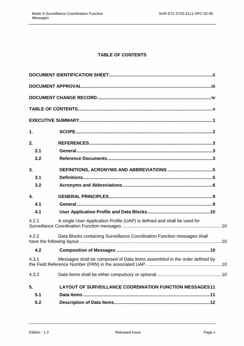
TABLE OF CONTENTS
DOCUMENT IDENTIFICATION SHEET.................................................................................ii
DOCUMENT APPROVAL.....................................................................................................iii
DOCUMENT CHANGE RECORD.........................................................................................iv
TABLE OF CONTENTS.........................................................................................................v
EXECUTIVE SUMMARY........................................................................................................1
1. SCOPE...........................................................................................................2
2. REFERENCES................................................................................................3
2.1 General ..........................................................................................................3
2.2 Reference Documents..................................................................................3
3. DEFINITIONS, ACRONYMS AND ABBREVIATIONS ...................................5
3.1 Definitions.....................................................................................................5
3.2 Acronyms and Abbreviations ......................................................................6
4. GENERAL PRINCIPLES.................................................................................9
4.1 General ..........................................................................................................9
4.1 User Application Profile and Data Blocks.................................................10
4.2.1 A single User Application Profile (UAP) is defined and shall be used for Surveillance Coordination Function messages. .............................................................................10
4.2.2 Data Blocks containing Surveillance Coordination Function messages shall have the following layout. ..............................................................................................................10
4.2 Composition of Messages .........................................................................10
4.3.1 Messages shall be composed of Data Items assembled in the order defined by the Field Reference Number (FRN) in the associated UAP. ..........................................................10
4.3.2 Data Items shall be either compulsory or optional...................................................10
5. LAYOUT OF SURVEILLANCE COORDINATION FUNCTION MESSAGES11
5.1 Data Items ...................................................................................................11
5.2 Description of Data Items...........................................................................12
SUR.ET2.ST03.3111-SPC-02-00 Mode S Surveillance Coordination Function Messages
Page vi Released Issue Edition : 1.3
5.2.1 Data Item I017/000, Message Type .......................................................................12
5.2.2 Data Item I017/010, Data Source Identifier .............................................................13
5.2.3 Data Item I017/012, Data Destination Identifier.......................................................13
5.2.4 Data Item I017/045 Calculated Position in WGS-84 Coordinates............................14
5.2.5 Data Item I017/050 Flight Level in Binary Representation ......................................15
5.2.6 Data Item I017/070, Mode 3/A Code in Octal Representation.................................16
5.2.7 Data Item I017/140, Time of Day ............................................................................17
5.2.8 Data Item I017/200, Track Velocity in Polar Co-ordinates.......................................18
5.2.9 Data Item I017/210, Mode S Address List...............................................................19
5.2.10 Data Item I017/220, Aircraft Address ......................................................................19
5.2.11 Data Item I017/221, Duplicate Address Reference Number (DRN).........................20
5.2.12 Data Item I017/230, Transponder Capability..........................................................21
5.2.13 Data Item I017/240, Track Status ...........................................................................22
5.2.14 Data Item I017/350, Cluster Station/Node List ........................................................23
5.2.15 Data Item I017/360, Cluster Controller Command State .........................................24
5.3 Transmission of Surveillance Co-ordination Function Messages ..........25
5.3.1 User Application Profile .........................................................................................25
5.3.2 Encoding Rules ......................................................................................................26
Mode S Surveillance Coordination Function Messages
SUR.ET2.ST03.3111-SPC-02-00
Edition : 1.3 Released Issue Page 1
EXECUTIVE SUMMARY
SUR.ET2.ST03.3111-SPC-02-00 Mode S Surveillance Coordination Function Messages
Page 2 Released Issue Edition : 1.3
1. SCOPE
1.1 This document describes the message structure for the transmission of Mode S Surveillance Coordination Function messages between Mode S ground interrogators.
1.2 Surveillance Coordination Function messages are ASTERIX data out of Data Category 017.

Mode S Surveillance Coordination Function Messages
SUR.ET2.ST03.3111-SPC-02-00
Edition : 1.3 Released Issue Page 3
2. REFERENCES
2.1 General
At the time of publication of this ASTERIX specification, the editions indicated for the referenced documents and standards were valid.
In the case of a conflict between the requirements of this document and the contents of the other referenced documents, this document shall take precedence.
2.2 Reference Documents
1. Eurocontrol Standard 000-1-92. Directives for the Uniform Drafting and Presentation of Eurocontrol Standard Documents. 1992.
2. Eurocontrol Standard SUR.ET1.ST05.2000-STD-01-01. All Purpose Structured Eurocontrol Radar Information Exchange - ASTERIX.
SUR.ET2.ST03.3111-SPC-02-00 Mode S Surveillance Coordination Function Messages
Page 4 Released Issue Edition : 1.3
This page is intentionally left blank
Mode S Surveillance Coordination Function Messages
SUR.ET2.ST03.3111-SPC-02-00
Edition : 1.3 Released Issue Page 5
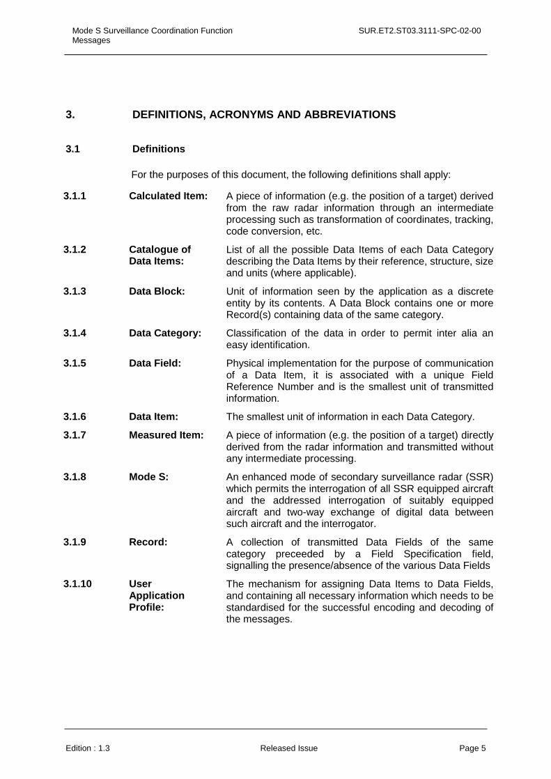
3. DEFINITIONS, ACRONYMS AND ABBREVIATIONS
3.1 Definitions
For the purposes of this document, the following definitions shall apply:
3.1.1 Calculated Item: A piece of information (e.g. the position of a target) derived from the raw radar information through an intermediate processing such as transformation of coordinates, tracking, code conversion, etc.
3.1.2 Catalogue of Data Items:
List of all the possible Data Items of each Data Category describing the Data Items by their reference, structure, size and units (where applicable).
3.1.3 Data Block: Unit of information seen by the application as a discrete entity by its contents. A Data Block contains one or more Record(s) containing data of the same category.
3.1.4 Data Category: Classification of the data in order to permit inter alia an easy identification.
3.1.5 Data Field: Physical implementation for the purpose of communication of a Data Item, it is associated with a unique Field Reference Number and is the smallest unit of transmitted information.
3.1.6 Data Item: The smallest unit of information in each Data Category.
3.1.7 Measured Item: A piece of information (e.g. the position of a target) directly derived from the radar information and transmitted without any intermediate processing.
3.1.8 Mode S: An enhanced mode of secondary surveillance radar (SSR) which permits the interrogation of all SSR equipped aircraft and the addressed interrogation of suitably equipped aircraft and two-way exchange of digital data between such aircraft and the interrogator.
3.1.9 Record: A collection of transmitted Data Fields of the same category preceeded by a Field Specification field, signalling the presence/absence of the various Data Fields
3.1.10 User Application Profile:
The mechanism for assigning Data Items to Data Fields, and containing all necessary information which needs to be standardised for the successful encoding and decoding of the messages.
SUR.ET2.ST03.3111-SPC-02-00 Mode S Surveillance Coordination Function Messages
Page 6 Released Issue Edition : 1.3
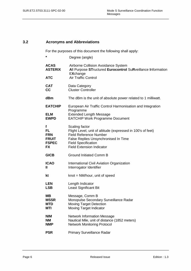
3.2 Acronyms and Abbreviations
For the purposes of this document the following shall apply:
°°°° Degree (angle) ACAS Airborne Collision Avoidance System ASTERIX All Purpose STructured Eurocontrol SuRveillance Information EXchange ATC Air Traffic Control CAT Data Category CC Cluster Controller dBm The dBm is the unit of absolute power related to 1 milliwatt. EATCHIP European Air Traffic Control Harmonisation and Integration
Programme ELM Extended Length Message EWPD EATCHIP Work Programme Document f Scaling factor FL Flight Level, unit of altitude (expressed in 100's of feet) FRN Field Reference Number FRUIT False Replies Unsynchronised In Time FSPEC Field Specification FX Field Extension Indicator GICB Ground Initiated Comm B ICAO International Civil Aviation Organization II Interrogator Identifier kt knot = NM/hour, unit of speed LEN Length Indicator LSB Least Significant Bit MB Message, Comm B MSSR Monopulse Secondary Surveillance Radar MTD Moving Target Detection MTI Moving Target Indicator NIM Network Information Message NM Nautical Mile, unit of distance (1852 meters) NMP Network Monitoring Protocol PSR Primary Surveillance Radar
Mode S Surveillance Coordination Function Messages
SUR.ET2.ST03.3111-SPC-02-00
Edition : 1.3 Released Issue Page 7
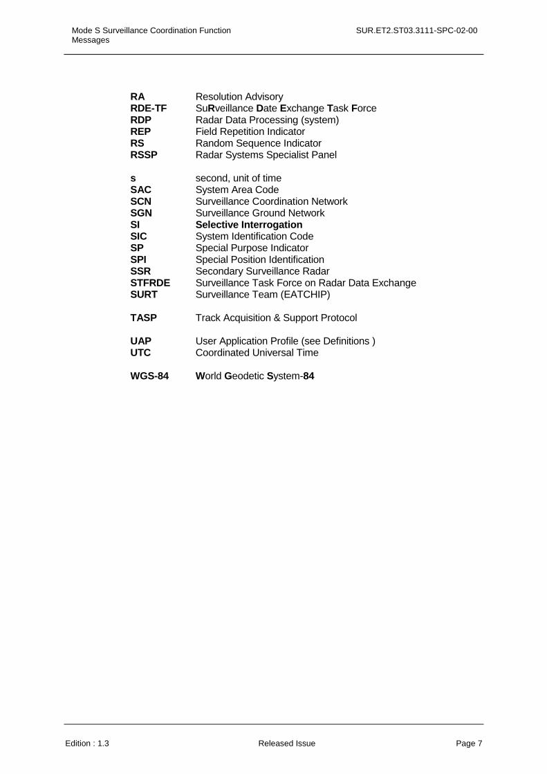
RA Resolution Advisory RDE-TF SuRveillance Date Exchange Task Force RDP Radar Data Processing (system) REP Field Repetition Indicator RS Random Sequence Indicator RSSP Radar Systems Specialist Panel s second, unit of time SAC System Area Code SCN Surveillance Coordination Network SGN Surveillance Ground Network SI Selective Interrogation SIC System Identification Code SP Special Purpose Indicator SPI Special Position Identification SSR Secondary Surveillance Radar STFRDE Surveillance Task Force on Radar Data Exchange SURT Surveillance Team (EATCHIP) TASP Track Acquisition & Support Protocol UAP User Application Profile (see Definitions ) UTC Coordinated Universal Time WGS-84 World Geodetic System-84

SUR.ET2.ST03.3111-SPC-02-00 Mode S Surveillance Coordination Function Messages
Page 8 Released Issue Edition : 1.3
This page is intentionally left blank
Mode S Surveillance Coordination Function Messages
SUR.ET2.ST03.3111-SPC-02-00
Edition : 1.3 Released Issue Page 9
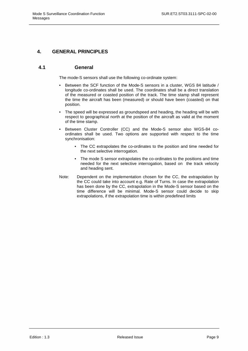
4. GENERAL PRINCIPLES
4.1 General
The mode-S sensors shall use the following co-ordinate system:
• Between the SCF function of the Mode-S sensors in a cluster, WGS 84 latitude / longitude co-ordinates shall be used. The coordinates shall be a direct translation of the measured or coasted position of the track. The time stamp shall represent the time the aircraft has been (measured) or should have been (coasted) on that position.
• The speed will be expressed as groundspeed and heading, the heading will be with respect to geographical north at the position of the aircraft as valid at the moment of the time stamp.
• Between Cluster Controller (CC) and the Mode-S sensor also WGS-84 co-ordinates shall be used. Two options are supported with respect to the time synchronisation:
• The CC extrapolates the co-ordinates to the position and time needed for the next selective interrogation.
• The mode S sensor extrapolates the co-ordinates to the positions and time needed for the next selective interrogation, based on the track velocity and heading sent.
Note: Dependent on the implementation chosen for the CC, the extrapolation by the CC could take into account e.g. Rate of Turns. In case the extrapolation has been done by the CC, extrapolation in the Mode-S sensor based on the time difference will be minimal. Mode-S sensor could decide to skip extrapolations, if the extrapolation time is within predefined limits
SUR.ET2.ST03.3111-SPC-02-00 Mode S Surveillance Coordination Function Messages
Page 10 Released Issue Edition : 1.3
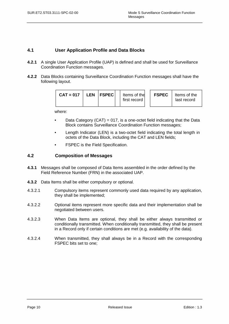
4.1 User Application Profile and Data Blocks
4.2.1 A single User Application Profile (UAP) is defined and shall be used for Surveillance Coordination Function messages.
4.2.2 Data Blocks containing Surveillance Coordination Function messages shall have the following layout.
CAT = 017 LEN FSPEC Items of the first record
FSPEC Items of the last record
where:
• Data Category (CAT) = 017, is a one-octet field indicating that the Data Block contains Surveillance Coordination Function messages;
• Length Indicator (LEN) is a two-octet field indicating the total length in octets of the Data Block, including the CAT and LEN fields;
• FSPEC is the Field Specification.
4.2 Composition of Messages
4.3.1 Messages shall be composed of Data Items assembled in the order defined by the Field Reference Number (FRN) in the associated UAP.
4.3.2 Data Items shall be either compulsory or optional.
4.3.2.1 Compulsory items represent commonly used data required by any application, they shall be implemented;
4.3.2.2 Optional items represent more specific data and their implementation shall be negotiated between users.
4.3.2.3 When Data Items are optional, they shall be either always transmitted or conditionally transmitted. When conditionally transmitted, they shall be present in a Record only if certain conditions are met (e.g. availability of the data).
4.3.2.4 When transmitted, they shall always be in a Record with the corresponding FSPEC bits set to one;
Mode S Surveillance Coordination Function Messages
SUR.ET2.ST03.3111-SPC-02-00
Edition : 1.3 Released Issue Page 11
5. LAYOUT OF SURVEILLANCE COORDINATION FUNCTION MESSAGES
5.1 Data Items
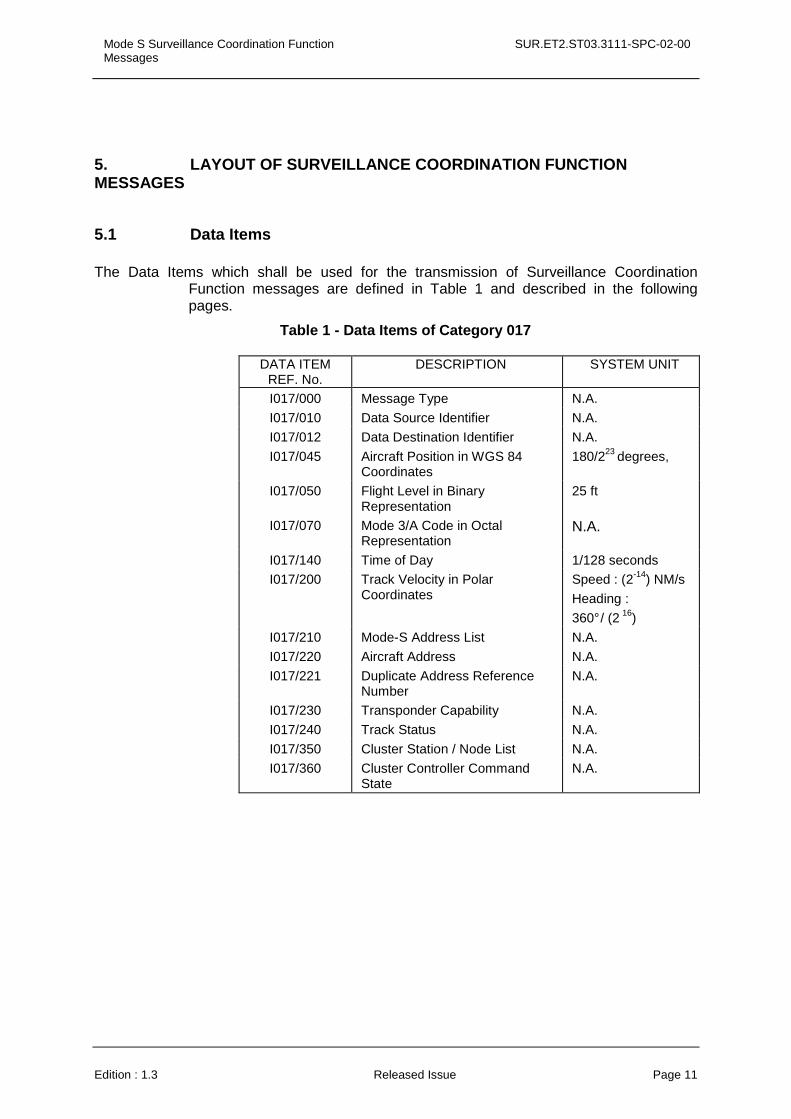
The Data Items which shall be used for the transmission of Surveillance Coordination Function messages are defined in Table 1 and described in the following pages.
Table 1 - Data Items of Category 017
DATA ITEM REF. No.
DESCRIPTION SYSTEM UNIT
I017/000 Message Type N.A.
I017/010 Data Source Identifier N.A.
I017/012 Data Destination Identifier N.A.
I017/045 Aircraft Position in WGS 84 Coordinates
180/223 degrees,
I017/050 Flight Level in Binary Representation
25 ft
I017/070 Mode 3/A Code in Octal Representation
N.A.
I017/140 Time of Day 1/128 seconds
I017/200 Track Velocity in Polar Coordinates
Speed : (2-14) NM/s
Heading :
360° / (2 16)
I017/210 Mode-S Address List N.A.
I017/220 Aircraft Address N.A.
I017/221 Duplicate Address Reference Number
N.A.
I017/230 Transponder Capability N.A.
I017/240 Track Status N.A.
I017/350 Cluster Station / Node List N.A.
I017/360 Cluster Controller Command State
N.A.
SUR.ET2.ST03.3111-SPC-02-00 Mode S Surveillance Coordination Function Messages
Page 12 Released Issue Edition : 1.3
5.2 Description of Data Items
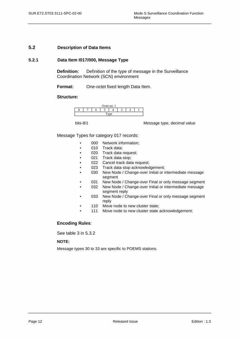
5.2.1 Data Item I017/000, Message Type
Definition: Definition of the type of message in the Surveillance Coordination Network (SCN) environment Format: One-octet fixed length Data Item. Structure:
Octet no. 1
8 7 6 5 4 3 2 1 Type
bits-8/1 Message type, decimal value
Message Types for category 017 records:
• 000 Network information; • 010 Track data; • 020 Track data request; • 021 Track data stop; • 022 Cancel track data request; • 023 Track data stop acknowledgement; • 030 New Node / Change-over Initial or intermediate message
segment • 031 New Node / Change-over Final or only message segment • 032 New Node / Change-over Initial or intermediate message
segment reply • 033 New Node / Change-over Final or only message segment
reply • 110 Move node to new cluster state; • 111 Move node to new cluster state acknowledgement;
Encoding Rules:
See table 3 in 5.3.2
NOTE:
Message types 30 to 33 are specific to POEMS stations.

Mode S Surveillance Coordination Function Messages
SUR.ET2.ST03.3111-SPC-02-00
Edition : 1.3 Released Issue Page 13
5.2.2 Data Item I017/010, Data Source Identifier
Definition: Identification of the source node for the SCN data Format: Two-octets fixed length Data Item. Structure:
Octet no. 1 Octet no. 2
16 15 14 13 12 11 10 9 8 7 6 5 4 3 2 1 SAC SIC
bits-16/9 (SAC) System Area Code bits-8/1 (SIC) System Identity Code
Encoding Rules:
See table 3 in 5.3.2
NOTE - The up-to-date list of SACs is published on the Eurocontrol Web Site (http://www.eurocontrol.int/asterix).
5.2.3 Data Item I017/012, Data Destination Identifier
Definition: Identification of the destination node for the SCN data. Format: Two-octets fixed length Data Item. Structure:
Octet no. 1 Octet no. 2
16 15 14 13 12 11 10 9 8 7 6 5 4 3 2 1 SAC SIC
bits-16/9 (SAC) System Area Code Bits--8/1 (SIC) System Identity Code
Encoding Rules:
See table 3 in 5.3.2
NOTE - The up-to-date list of SACs is published on the Eurocontrol Web Site (http://www.eurocontrol.int).
SUR.ET2.ST03.3111-SPC-02-00 Mode S Surveillance Coordination Function Messages
Page 14 Released Issue Edition : 1.3
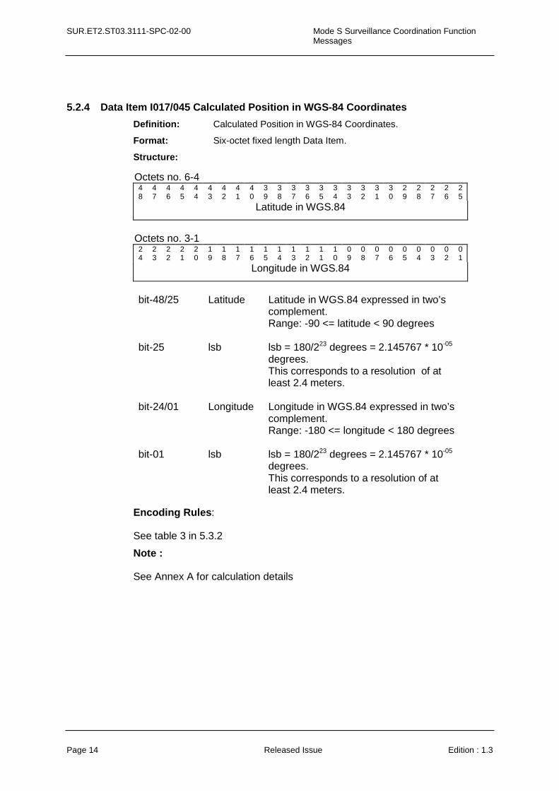
5.2.4 Data Item I017/045 Calculated Position in WGS-84 Coordinates
Definition: Calculated Position in WGS-84 Coordinates.
Format: Six-octet fixed length Data Item.
Structure:
Octets no. 6-4 48
47
46
45
44
43
42
41
40
39
38
37
36
35
34
33
32
31
30
29
28
27
26
25
Latitude in WGS.84
Octets no. 3-1
24
23
22
21
20
19
18
17
16
15
14
13
12
11
10
09
08
07
06
05
04
03
02
01
Longitude in WGS.84
bit-48/25 Latitude Latitude in WGS.84 expressed in two’s
complement. Range: -90 <= latitude < 90 degrees
bit-25 lsb lsb = 180/223 degrees = 2.145767 * 10-05 degrees. This corresponds to a resolution of at least 2.4 meters.
bit-24/01 Longitude Longitude in WGS.84 expressed in two’s
complement. Range: -180 <= longitude < 180 degrees
bit-01 lsb lsb = 180/223 degrees = 2.145767 * 10-05 degrees. This corresponds to a resolution of at least 2.4 meters.
Encoding Rules:
See table 3 in 5.3.2
Note :
See Annex A for calculation details

Mode S Surveillance Coordination Function Messages
SUR.ET2.ST03.3111-SPC-02-00
Edition : 1.3 Released Issue Page 15
5.2.5 Data Item I017/050 Flight Level in Binary Representation Definition: Flight Level of the Aircraft Format: Two-octets fixed length Data Item. Structure:
Octet no. 1 Octet no. 2
16 15 14 13 12 11 10 9 8 7 6 5 4 3 2 1 V G Altitude
bits-16 (V) = 0 Code validated = 1 Code not validated bit-15 (G) = 0 Default =1 Garbled code / Error correction applied bits-14/1 Altitude in binary representation, (LSB) = 1/4
FL = 25 ft.
Encoding Rules:
See table 3 in 5.3.2
NOTES 1. The value shall be within the range described by ICAO Annex 10
2. Bit-15 (G) is set to one when an error correction has been attempted
3. In case of a track miss (coasted position) the flight level sent will be either the predicted flight level from the vertical tracking or the last measured flight level, if no vertical tracking is performed. Bit 7 (FLT) of I017/240 (Track Status) indicates whether vertical tracking was performed or not.
SUR.ET2.ST03.3111-SPC-02-00 Mode S Surveillance Coordination Function Messages
Page 16 Released Issue Edition : 1.3
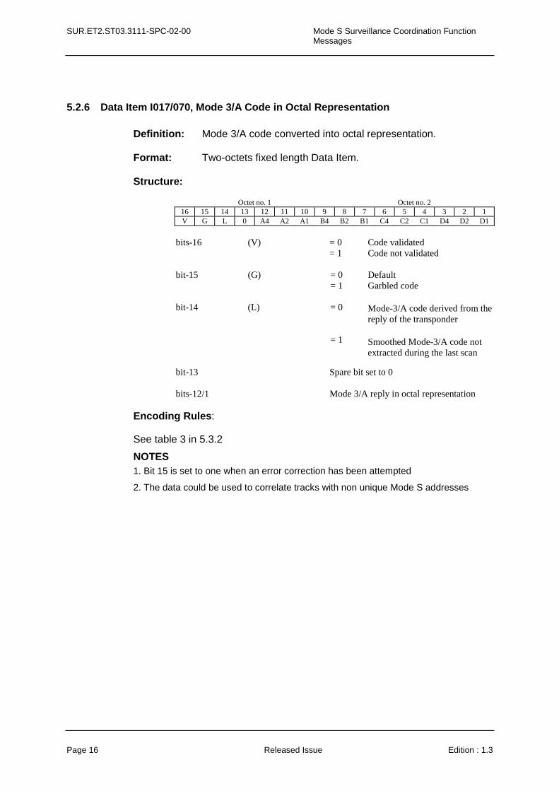
5.2.6 Data Item I017/070, Mode 3/A Code in Octal Representation Definition: Mode 3/A code converted into octal representation. Format: Two-octets fixed length Data Item. Structure:
Octet no. 1 Octet no. 2
16 15 14 13 12 11 10 9 8 7 6 5 4 3 2 1 V G L 0 A4 A2 A1 B4 B2 B1 C4 C2 C1 D4 D2 D1
bits-16 (V) = 0 Code validated = 1 Code not validated bit-15 bit-14
(G) (L)
= 0 = 1 = 0 = 1
Default Garbled code
Mode-3/A code derived from the reply of the transponder
Smoothed Mode-3/A code not extracted during the last scan
bit-13 Spare bit set to 0 bits-12/1 Mode 3/A reply in octal representation
Encoding Rules:
See table 3 in 5.3.2
NOTES 1. Bit 15 is set to one when an error correction has been attempted
2. The data could be used to correlate tracks with non unique Mode S addresses
Mode S Surveillance Coordination Function Messages
SUR.ET2.ST03.3111-SPC-02-00
Edition : 1.3 Released Issue Page 17
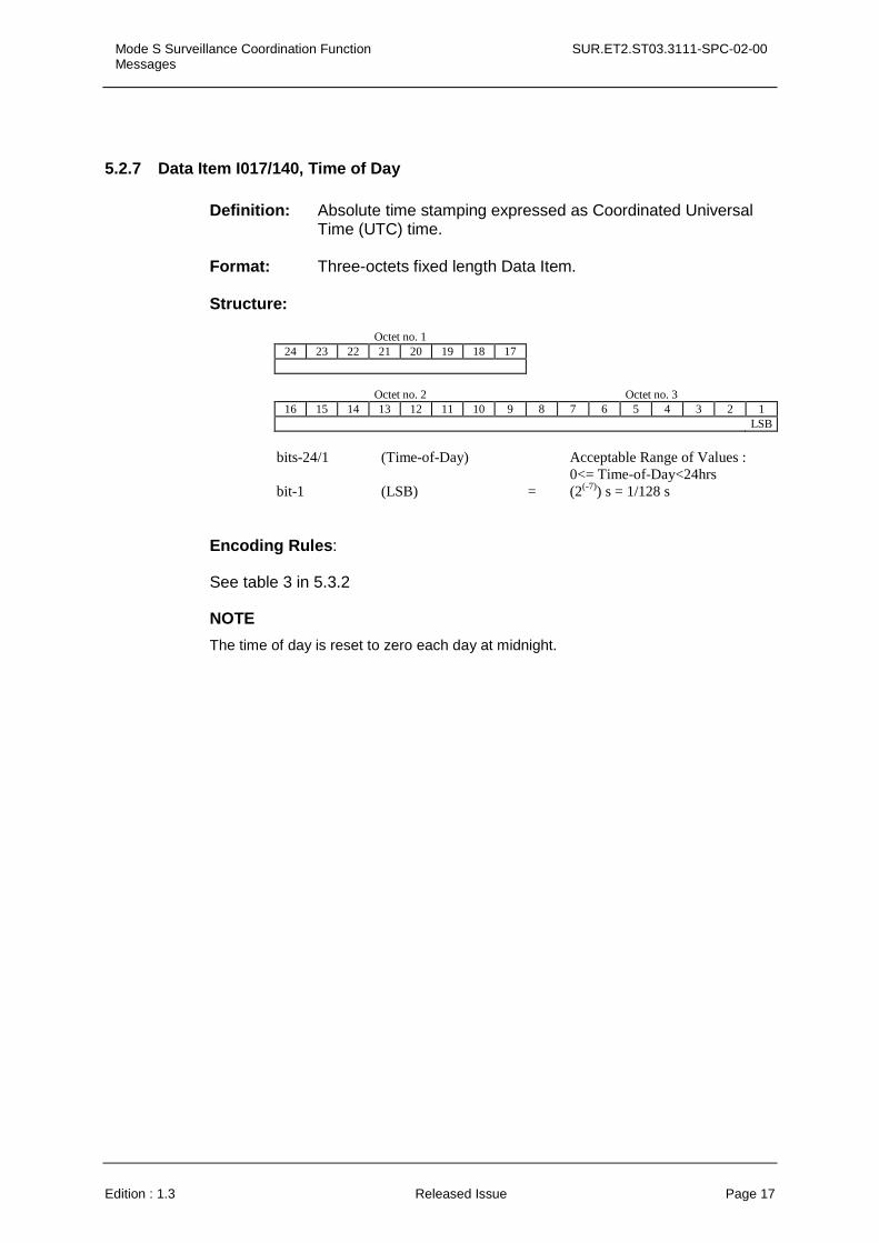
5.2.7 Data Item I017/140, Time of Day Definition: Absolute time stamping expressed as Coordinated Universal Time (UTC) time. Format: Three-octets fixed length Data Item. Structure:
Octet no. 1
24 23 22 21 20 19 18 17
Octet no. 2 Octet no. 3
16 15 14 13 12 11 10 9 8 7 6 5 4 3 2 1 LSB
bits-24/1 (Time-of-Day) Acceptable Range of Values :
0<= Time-of-Day<24hrs bit-1 (LSB) = (2(-7)) s = 1/128 s
Encoding Rules:
See table 3 in 5.3.2
NOTE
The time of day is reset to zero each day at midnight.

SUR.ET2.ST03.3111-SPC-02-00 Mode S Surveillance Coordination Function Messages
Page 18 Released Issue Edition : 1.3
5.2.8 Data Item I017/200, Track Velocity in Polar Co-ordinates
Definition: Calculated track velocity expressed in polar co-ordinates. The heading is the heading with respect to the geographical north at the aircraft position. For clarification see annex A, paragraph5.
Format: Four-octet fixed length Data Item.
Structure:
Octet no. 1 Octet no. 2
32 31 30 29 28 27 26 25 24 23 22 21 20 19 18 17 CALCULATED GROUNDSPEED (max. 2 NM/s) LSB
Octet no. 3 Octet no. 4
16 15 14 13 12 11 10 9 8 7 6 5 4 3 2 1 CALCULATED HEADING LSB
bit-17 (LSB) = (2-14) NM/s = 0.22 kt bit-1 (LSB) = 360°/(2 16) = 0.005 5°
Encoding Rules:
See table 3 in 5.3.2

Mode S Surveillance Coordination Function Messages
SUR.ET2.ST03.3111-SPC-02-00
Edition : 1.3 Released Issue Page 19
5.2.9 Data Item I017/210, Mode S Address List
Definition: List of technical Mode S addresses.
Format: Repetitive Data Item starting with a one-octet Repetition Factor followed by at least one Mode S Address of 3-octets length.
Structure:
Octet no. 1 Octet no. 2 32 31 30 29 28 27 26 25 24 23 22 21 20 19 18 17
REP Mode S Address
Octet no. 3 Octet no. 4 16 15 14 13 12 11 10 9 8 7 6 5 4 3 2 1
Mode S Address
bits-32/25 (REP) Repetition factor bits-24/1 24-bits Mode S address, A23 to A0
Encoding Rules:
See table 3 in 5.3.2
This data item shall be sent even if there is no Mode S Address. In this case it is reduced in length to one octet only (REP =0) with all bits set to zero.
5.2.10 Data Item I017/220, Aircraft Address
Definition: Aircraft address (24-bits Mode S address) assigned uniquely to each aircraft. Format: Three-octets fixed length Data Item. Structure:
Octet no. 1
24 23 22 21 20 19 18 17 MSB
Octet no. 2 Octet no. 3
16 15 14 13 12 11 10 9 8 7 6 5 4 3 2 1 LSB
bits-24/1 24-bits Mode S address, A23 to A0
Encoding Rules:
See table 3 in 5.3.2
SUR.ET2.ST03.3111-SPC-02-00 Mode S Surveillance Coordination Function Messages
Page 20 Released Issue Edition : 1.3
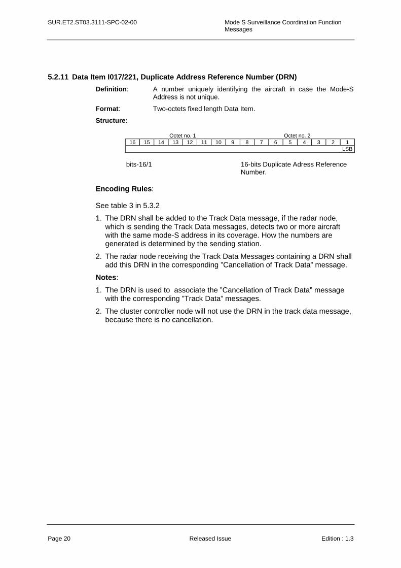
5.2.11 Data Item I017/221, Duplicate Address Reference Number (DRN)
Definition: A number uniquely identifying the aircraft in case the Mode-S Address is not unique.
Format: Two-octets fixed length Data Item.
Structure:
Octet no. 1 Octet no. 2 16 15 14 13 12 11 10 9 8 7 6 5 4 3 2 1
LSB
bits-16/1 16-bits Duplicate Adress Reference
Number. Encoding Rules:
See table 3 in 5.3.2
1. The DRN shall be added to the Track Data message, if the radar node, which is sending the Track Data messages, detects two or more aircraft with the same mode-S address in its coverage. How the numbers are generated is determined by the sending station.
2. The radar node receiving the Track Data Messages containing a DRN shall add this DRN in the corresponding ”Cancellation of Track Data” message.
Notes:
1. The DRN is used to associate the ”Cancellation of Track Data” message with the corresponding ”Track Data” messages.
2. The cluster controller node will not use the DRN in the track data message, because there is no cancellation.

Mode S Surveillance Coordination Function Messages
SUR.ET2.ST03.3111-SPC-02-00
Edition : 1.3 Released Issue Page 21
5.2.12 Data Item I017/230, Transponder Capability
Definition: Communications capability of the transponder received in the All-Call reply when the aircraft is initially acquired.
Format: One-octet fixed length Data Item.
Structure:
Octet no. 1 8 7 6 5 4 3 2 1
CA SI spare
bits-8/6 (CA) Communications capability of the transponder = 0 No communications capability
(surveillance only), no ability to set CA code 7 either airborne or on the ground
= 1 Reserved = 2 Reserved = 3 Reserved = 4 at least Comm. A and Comm. B capability
and the ability to set CA code 7 and on the ground
= 5 at least Comm. A and Comm. B capability and the ability to set CA code 7 and airborne
= 6 at least Comm. A and Comm. B capability and the ability to set CA code 7 and either airborne or on the ground
= 7 signifies the DR field is not equal to 0 or the FS field equals 2, 3, 4 or 5 and either airborne or on the ground
bit 5 (SI) SI/II-capabilities of the transponder = 0 transponder SI capable = 1 transponder not SI capable bits-5/1 (SPARE) spare bits set to zero
Encoding Rules:
See table 3 in 5.3.2

SUR.ET2.ST03.3111-SPC-02-00 Mode S Surveillance Coordination Function Messages
Page 22 Released Issue Edition : 1.3
5.2.13 Data Item I017/240, Track Status
Definition: Status of the track position
Format: One-octet fixed length Data Item.
Structure:
Octet no. 1 8 7 6 5 4 3 2 1
CST FLT spare
bit-8 (CST) Track Coasted = 0 Measured position = 1 No measured position (coasted) bit-7 (FLT) Flight Level Tracking = 0 Last Measured Flight Level = 1 Predicted Flight Level bits-6/1 (SPARE) spare bits set to zero
Encoding Rules:
See table 3 in 5.3.2
This item shall not be sent when CST and FLT equal zero.
Mode S Surveillance Coordination Function Messages
SUR.ET2.ST03.3111-SPC-02-00
Edition : 1.3 Released Issue Page 23
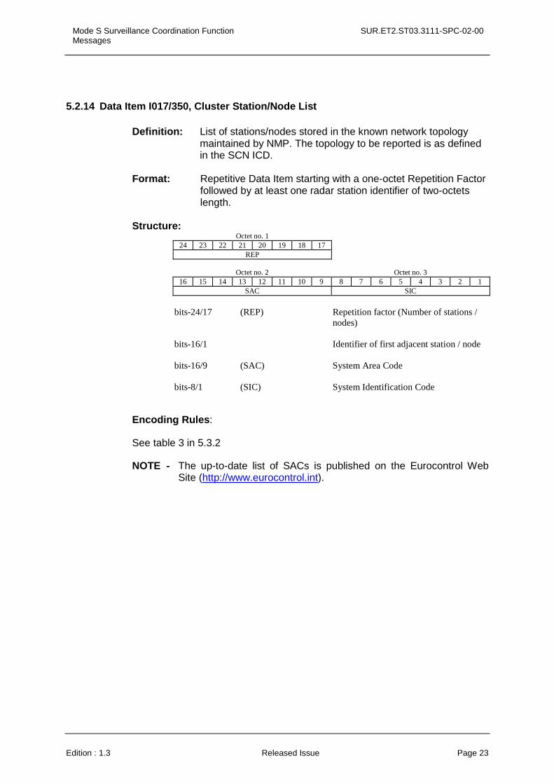
5.2.14 Data Item I017/350, Cluster Station/Node List
Definition: List of stations/nodes stored in the known network topology maintained by NMP. The topology to be reported is as defined in the SCN ICD.
Format: Repetitive Data Item starting with a one-octet Repetition Factor followed by at least one radar station identifier of two-octets length. Structure:
Octet no. 1 24 23 22 21 20 19 18 17
REP
Octet no. 2 Octet no. 3 16 15 14 13 12 11 10 9 8 7 6 5 4 3 2 1
SAC SIC
bits-24/17 (REP) Repetition factor (Number of stations /
nodes) bits-16/1 Identifier of first adjacent station / node bits-16/9 (SAC) System Area Code bits-8/1 (SIC) System Identification Code
Encoding Rules:
See table 3 in 5.3.2
NOTE - The up-to-date list of SACs is published on the Eurocontrol Web Site (http://www.eurocontrol.int).

SUR.ET2.ST03.3111-SPC-02-00 Mode S Surveillance Coordination Function Messages
Page 24 Released Issue Edition : 1.3
5.2.15 Data Item I017/360, Cluster Controller Command State
Definition: Defines the current mode and state in which a cluster station, the radar node taking part in the cluster, should be operating. Format: One-octet fixed length Data Item. Structure:
Octet no. 1
8 7 6 5 4 3 2 1 State
bits-8/1 Station state Value (0 -255) of state number to be
selected
Encoding Rules:
See table 3 in 5.3.2
NOTE - The Cluster Controller will use this field to select the state in which a cluster station should be operating and the cluster station will use this field to indicate to the cluster controller the adopted state.
Mode S Surveillance Coordination Function Messages
SUR.ET2.ST03.3111-SPC-02-00
Edition : 1.3 Released Issue Page 25
5.3 Transmission of Surveillance Co-ordination Function Messages
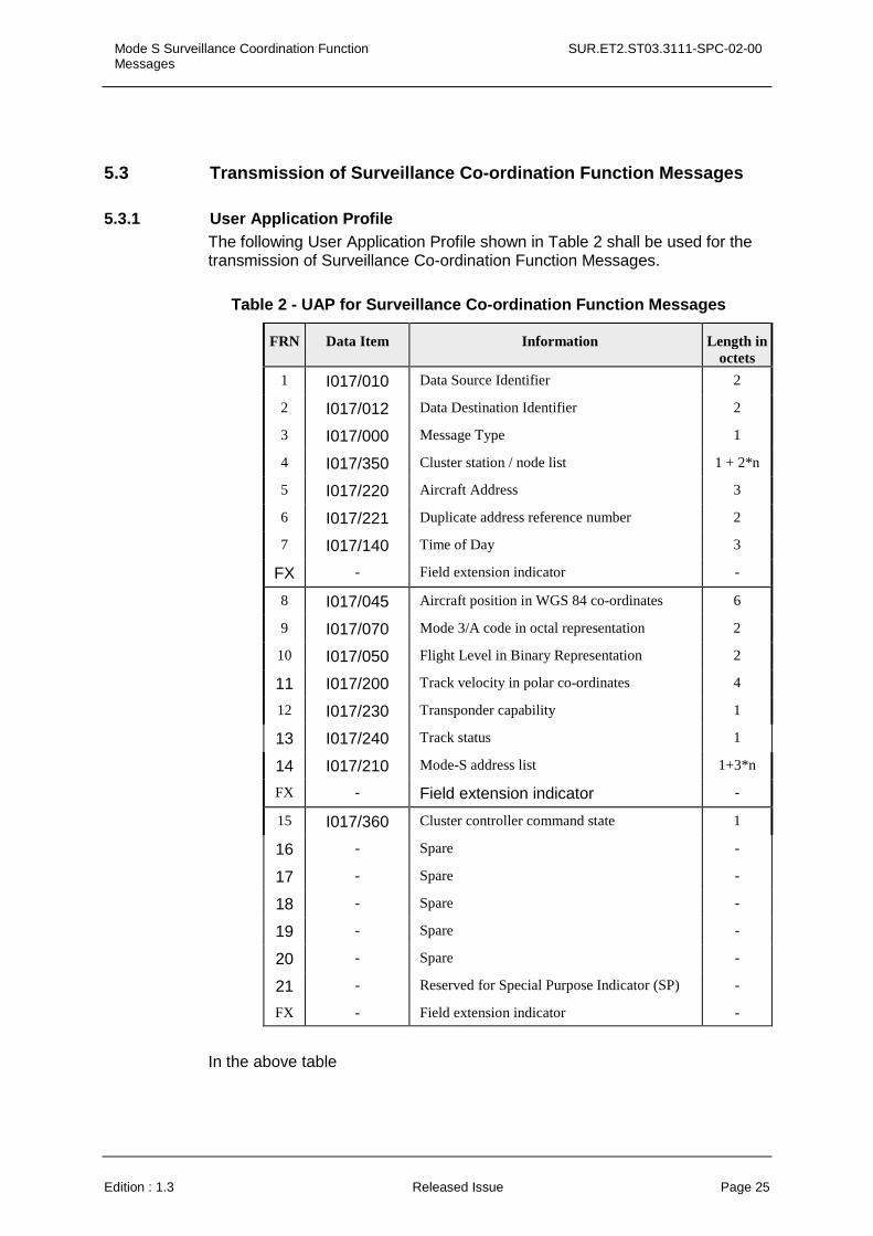
5.3.1 User Application Profile The following User Application Profile shown in Table 2 shall be used for the transmission of Surveillance Co-ordination Function Messages.
Table 2 - UAP for Surveillance Co-ordination Function Messages
FRN Data Item Information Length in octets
1 I017/010 Data Source Identifier 2
2 I017/012 Data Destination Identifier 2
3 I017/000 Message Type 1
4 I017/350 Cluster station / node list 1 + 2*n
5 I017/220 Aircraft Address 3
6 I017/221 Duplicate address reference number 2
7 I017/140 Time of Day 3
FX - Field extension indicator -
8 I017/045 Aircraft position in WGS 84 co-ordinates 6
9 I017/070 Mode 3/A code in octal representation 2
10 I017/050 Flight Level in Binary Representation 2
11 I017/200 Track velocity in polar co-ordinates 4
12 I017/230 Transponder capability 1
13 I017/240 Track status 1
14 I017/210 Mode-S address list 1+3*n
FX - Field extension indicator -
15 I017/360 Cluster controller command state 1
16 - Spare -
17 - Spare -
18 - Spare -
19 - Spare -
20 - Spare -
21 - Reserved for Special Purpose Indicator (SP) -
FX - Field extension indicator -
In the above table
SUR.ET2.ST03.3111-SPC-02-00 Mode S Surveillance Coordination Function Messages
Page 26 Released Issue Edition : 1.3
• the first column indicates the Field Reference Number (FRN) associated to each Data Item used in the UAP,
• the fourth column gives the format and the length of each item, a stand-alone figure indicates the octet-count of a fixed-length Data Item, 1+ indicates a variable-length Data Item comprising a first part of 1 octet followed by n-octets extents as necessary.
The maximum length of the corresponding FSPEC is three octets.
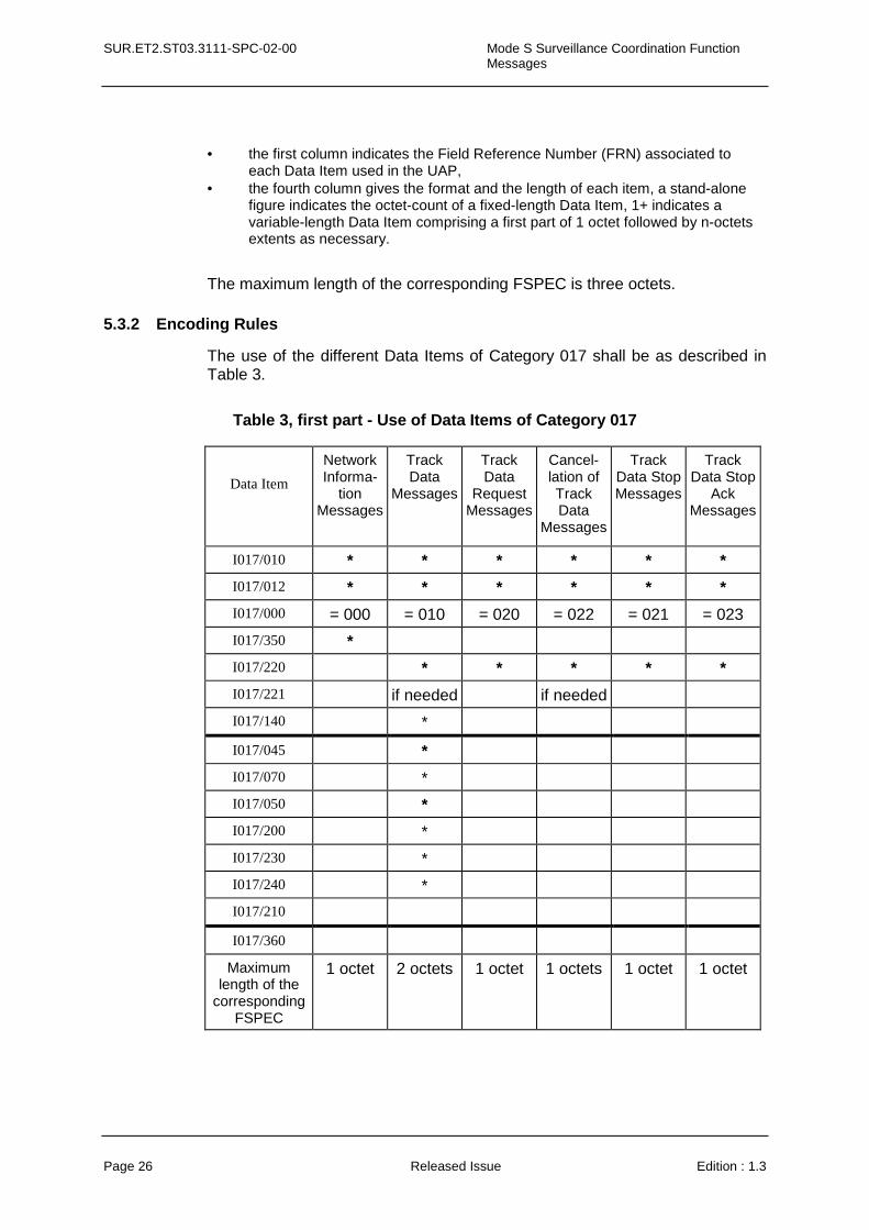
5.3.2 Encoding Rules
The use of the different Data Items of Category 017 shall be as described in Table 3.
Table 3, first part - Use of Data Items of Category 017
Data Item
Network Informa-
tion Messages
Track Data
Messages
Track Data
Request Messages
Cancel-lation of Track Data
Messages
Track Data Stop Messages
Track Data Stop
Ack Messages
I017/010 * * * * * *
I017/012 * * * * * *
I017/000 = 000 = 010 = 020 = 022 = 021 = 023
I017/350 *
I017/220 * * * * *
I017/221 if needed if needed
I017/140 *
I017/045 *
I017/070 *
I017/050 *
I017/200 *
I017/230 *
I017/240 *
I017/210
I017/360
Maximum length of the
corresponding FSPEC
1 octet 2 octets
1 octet 1 octets 1 octet 1 octet
Mode S Surveillance Coordination Function Messages
SUR.ET2.ST03.3111-SPC-02-00
Edition : 1.3 Released Issue Page 27
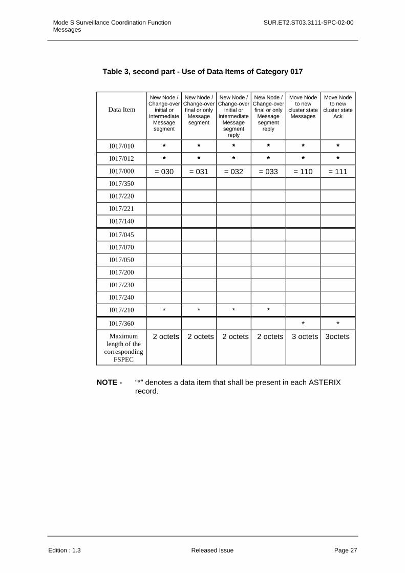
Table 3, second part - Use of Data Items of Category 017
Data Item
New Node / Change-over
initial or intermediate
Message segment
New Node / Change-over final or only Message segment
New Node / Change-over
initial or intermediate
Message segment
reply
New Node / Change-over final or only Message segment
reply
Move Node to new
cluster state Messages
Move Node to new
cluster state Ack
I017/010 * * * * * *
I017/012 * * * * * *
I017/000 = 030 = 031 = 032 = 033 = 110 = 111
I017/350
I017/220
I017/221
I017/140
I017/045
I017/070
I017/050
I017/200
I017/230
I017/240
I017/210 * * * *
I017/360 * *
Maximum length of the
corresponding FSPEC
2 octets 2 octets 2 octets 2 octets 3 octets 3octets
NOTE - “*” denotes a data item that shall be present in each ASTERIX record.