Embed Size (px)
Citation preview

Surround Cinema
SUB200 Amplifier/Subwoofer
SERVICE MANUAL
JBL Consumer Products 250 Crossways Park Dr.
Woodbury, New York 11797 Rev1 3/2005

Note: The SUB200 is part of the SCS200.7 system
Satellite loudspeakers SCS200SAT order JBL part# SCS200SAT-1 Center channel SCS200CEN order JBL part# SCS200/300 CEN-1
- CONTENTS -
BASIC SPECIFICATIONS……………….….….….….…………….1
DETAILED SPECIFICATIONS ……..…………….……………..2
OPERATION ………….……………………………..…………….4
CONNECTIONS..………………………..………….…….………...5
BASIC TROUBLESHOOTING…..…………….….….…….……...7
TEST SET-UP AND PROCEDURE……..……….…….………….8
EXPLODED VIEW/PARTS LIST…………………………………..9
120V BLOCK DIAGRAM..……………………….…………….....10
230V BLOCK DIAGRAM..………………………….………….....11
PCB DRAWINGS………………..………………………………...12
120V ELECTRICAL PARTS LIST …………….…….…………..18
230V ELECTRICAL PARTS LIST …………….….……………..22
INTEGRATED CIRCUIT/TRANSISTOR PINOUTS…………..26
120V SCHEMATICS.……….………………………..…. ………27
230V SCHEMATICS.………..……………………….…. ………29
PACKAGING…………………………….………………………...31
BASIC SPECIFICATIONS SUB200 Subwoofer Configuration: Floor-firing, bass-reflex ported enclosure Woofer: 8" (203mm) cone Amplifier Power output: 100W Continuous RMS power Frequency response: 35Hz – 160Hz (-6dB) Dimensions (including feet): 16 ¼ x 11 x 13 ¾” (413 x 279 x 349mm) Weight: 28 lb/12.7kg Occasional refinements may be made to existing products without notice but will always meet or exceed original specifications unless otherwise stated
SUB200 (SCS200.7 sys)
1

JBL SUB200 100W Powered Sub/ Plate Amp
LINE VOLTAGE Yes/No Hi/Lo Line Unit NotesUS 120VAC/60Hz Yes 108-132 Vrms Normal Operation
Asia 100VAC/50Hz Yes 90-110 Vrms Normal OperationEU 230VAC/50-60Hz Yes 207-264 Vrms Normal Operation Normal operation, MOMS required
Parameter Specification UnitQA Test Limits Conditions Notes
Amp SectionType (Class AB, D, other) AB AB N/A 120V System is Class ABType (Class AB, D, other) H H N/A 230V System is Class HLoad Impedance (speaker) 4 Ohms N/A Nominal
Rated Output Power 120V 100 Watts 85 @ Nominal input voltage
Different output power due to differences in amp configuration between 120V and 230V
Rated Output Power 230V 105 Watts 100 @ Nominal input voltage THD@ Rated Power 0.5 % 1 22K filterTHD @ 1 Watt 0.1 % 0.3 22K filterDC Offset 10 mV-DC 50 @ Speaker Output
Damping factor >100 DF 50Measured at speaker terminals, Output power 90 Watts THD 0.1 %
Input SensitivityInput Frequency 50 Hz 50 Nominal Freq.Line Input (L&R) 15 mVrms ±2dB To 1 Watt 1 input driven
LFE Input 9.5 mVrms ±2dB To 1 Watt LFE input driven onlySpeaker/Hi Level Input 245 mVrms ±2dB To 1 Watt (-20 dB below Line In)...1 input driven
Signal to NoiseSNR-A-Weighted 90 dBA 85 To Rated power A-Weighting filterSNR-unweighted 80 dBr 80 To Rated power 22KHz filterSNR @ 1W-unweighted 65 dBr 60 To 1 Watt 22KHz filter
Residual Noise Floor 1.5 mVrms 2.5Volume @max, using RMS reading DMM/VOM (or A/P)
Residual Noise Floor 1 mVrms(max) 2
Volume @max, w/ A/P Swept Bandpass Measurement (Line freq.+ harmonics)
Input ImpedanceLine input L&R , LFE >10 K ohms N/A Nominal over the audio BW Reference only
Speaker/Hi Level Input 4.7 K ohms N/A Nominal over the audio BW Reference only
FiltersLow Pass (fixed or variable) fixed -- ±2dB
Slope & Q dB/Octave N/ASubsonic filter (HPF) Hz ±2dB
Slope & Q dB/Octave N/A
Limiter (yes/no) YES -- N/ATHD at Max. Output Power N/A -- N/A
Features
LFE Input YES Functional BW Limited to 500 Hz, refer to ECR00031 & AP Curves
Volume pot Taper (lin/log) LOG -- Functional ATO YES Functional
Input ConfigurationLine In (L,R) L ,R -- Functional RCA inputs: L , R Summed to MonoLine level in LFE LFE FunctionalSpkr/Hi Level In (L,R) L,R -- Functional L R Summed to MonoSpkr Out: Level out (L,R)Hi P L,R Functional Direct by pass from Speaker in
Signal Sensing (ATO)Auto-Turn-On (yes/no) YES -- FunctionalATO Input Frequency 50 Hz Functional
ATO Level Line Level in (L,R 2 mV Functional2mV@50Hz into Line Input w/ 1 ch. driven
ATO Level Speaker in 40 mV Functional
SUB200 (SCS200.7sys)
2

Parameter Specification UnitQA Test Limits Conditions Notes
ATO Turn-on time 5 ms FunctionalAmp connected and AC on, then input signal applied
Auto Mute/ Turn-OFF Time 15 minutes FunctionalT before muting, after signal is removed Auto turn of time (T) must be 10 > T <15
Power on Delay time 3 sec. Functional AC Power Applied
Transients/PopsATO Transient 5 mV-peak 10 @ Speaker OutputsTurn-on Transient 50 mV-peak 100 @ Speaker Outputs AC Line cycled from OFF to ONTurn-off Transient 50 mV-peak 100 @ Speaker Outputs AC Line cycled from ON to OFF
Efficiency
Stand-by Input Power 12 Watts 13 @ nom. line voltage
Maximum allowable input power under nominal Input voltage and frequency, HOT or COLD operation.
Power Cons.@rated power 180 Watts 187 @ 120V-60 Hz (Nom.line voltage) 90 Watts @ 4 Ohms nominal line voltagePower Cons.@rated power 195 Watts 200 @ 230V-50 Hz (Nom.line voltage) 90 Watts @ 4 Ohms nominal line voltage
ProtectionShort Circuit Protection YES -- Functional Direct short at output
Thermal Protection 65 deg. C -- Functional @1/8 max unclipped Power Temperature rise should not exceed 35K rise
DC Offset Protection YES -- Functional DC present at Speaker Out leads Relay or crowbar (for driver/fire Line Fuse Rating
120VAC 2.5 Amps Type-T or Slo BloExternal fuse with UL/SEMKO rated holder
230VAC 1.25 Amps Type-T or Slo BloExternal fuse with UL/SEMKO rated holder
SUB200 (SCS200.7sys)
3

10
OPERATION
MIN MAX
SubwooferLevel
MIN MAX
SubwooferLevel
Move the Master Powerswitch (marked “Power” å)to the “•” (On) position touse the SUB200 subwoofer. If you will be away fromhome for an extended periodof time, or if the subwooferwill not be used, switch theMaster Power switch å tothe Off position.
VOLUME
∫
å
Volume may be adjustedusing the Subwoofer Levelcontrol ∫ as shown.
SUB200 (SCS200.7sys)
4

8
DOLBY PRO LOGIC* (NON-DIGITAL) – LINE LEVEL
Use this installation methodfor Dolby Pro Logic applica-tions (not Dolby Digital, DTSor other digital processing),where the receiver/proces-sor is equipped with a sub-woofer output, or a volume-controlled preamp (line-)level output:
Use RCA-type interconnectsto connect the line-level subwoofer outputs on yourreceiver or amplifier to theline-level inputs on the sub-woofer. IMPORTANT: Do notuse the LFE input on the sub-woofer with Dolby Pro Logicprocessors.
NOTE: If your receiver oramplifier only has one sub-woofer output jack, then youwill need to use a Y-connec-tor (not included). Plug themale end of the Y-connectorinto your receiver or ampli-fier’s subwoofer output jack,and connect each of the twofemale ends to separateRCA-type interconnects.Finally, plug the RCA-typeinterconnects into the line-level inputs on the sub-woofer.Connect each speaker to the corresponding speakerterminals on your receiver or amplifier.Make sure your receiver orprocessor is correctly con-figured to indicate that thesubwoofer is “On.”Note for advanced users: Ifyour receiver/processor hasa built-in low-pass crossoverfilter for the subwoofer out-put, you may use the LFEinput to bypass the sub-woofer’s internal crossover.
Use this installation methodfor Dolby Digital, DTS orother digital surroundprocessors: Use the line-level input jackmarked “LFE” for the Low-Frequency Effects channel.
Connect this jack to the LFEoutput or subwoofer output on your receiver or amplifier.Connect each speaker to thecorresponding speaker terminals on your receiver or amplifier.Make sure that you haveconfigured your surroundsound processor for “Sub-woofer On.” Also configureyour receiver for 5.1-, 6.1- or
7.1-channel operation asappropriate. The front left,front right, center and rearspeakers should all be set to“Small.” If your receiverallows you to set the cross-over frequency between thesubwoofer and the mainspeakers, select 120Hz or thesetting that is the closest fre-quency below it.
DOLBY* DIGITAL OR DTS®
(OR OTHER DIGITAL SURROUND MODE) CONNECTION
LINELEVEL
IN
LFE L RLFE OUT
SUBWOOFERRECEIVER
– +
– +
– +
– +
– +
– +– +
– +– +
Receiver
Subwoofer Out
LeftFront
LeftSurround
– +
RightFront
RightSurround
Subwoofer
R L
Center
Surround BackLeft
Line-Level In
Right Surround
Right Front
Left Surround
Left Front Center
R
L
– +
Surround BackLeft
– +
– +
Surround BackRight
– +
Surround BackRight
SUB200 (SCS200.7sys)
5

9
DOLBY PRO LOGIC (NON-DIGITAL) – SPEAKER LEVEL
Use this installation method for Dolby Pro Logic applica-tions (not Dolby Digital, DTSor other digital processing),where the receiver/processordoes not have a subwooferoutput, or a volume-controlledpreamp (line-) level output:
Connect your receiver oramplifier’s front left and rightspeaker terminals to the leftand right terminals on the subwoofer that are marked“Speaker Level In.” Connectthe left and right terminals on the subwoofer that aremarked “Speaker Level Out”to the corresponding termi-nals on the back of your frontleft and right speakers.
Connect your receiver oramplifier’s center, surroundand surround back speakerterminals to the correspon-ding terminals on the back of your center and surroundspeakers.
Right Front
Right Surround
Left Front
Left Surround
Center
– + – +
– +
– + – +– +
– +
– + – + – +
Left Front Center
Left Surround
Right Front
Right Surround
Surround BackLeft
Surround BackLeft
Subwoofer
Receiver
SPEAKER LEVEL
OUT IN
+R–
+R–
–L+
–L+
– +
– +
Surround BackRight
Surround BackRight
– + – +
SUB200 (SCS200.7sys)
6

If there is no sound from anyof the speakers:• Check that receiver/ampli-fier is on and a source isplaying.• Check that the powered subwoofer is plugged in, and its Power switch å isswitched on (“•” position).• Check all wires and con-nections between receiver/amplifier and speakers.Make sure all wires are con-nected. Make sure none ofthe speaker wires arefrayed, cut or punctured, ortouching each other.• Review proper operation ofyour receiver/amplifier.If there is no sound comingfrom one speaker:• Check the “Balance” controlon your receiver/amplifier.• Check all wires and con-nections between receiver/amplifier and speakers.Make sure all wires are con-nected. Make sure none ofthe speaker wires arefrayed, cut or punctured, ortouching each other.• In Dolby Digital or DTSmodes, make sure that thereceiver/processor is config-ured so that the speaker inquestion is enabled.• Turn off all electronics and switch the speaker inquestion with one of theother speakers that is work-ing correctly. Turn every-thing back on, and deter-mine whether the problemhas followed the speaker, orhas remained in the samechannel. If the problem is in the same channel, thesource of the problem is most likely with yourreceiver or amplifier, andyou should consult the
owner’s manual for thatproduct for further informa-tion. If the problem has fol-lowed the speaker, consultyour dealer for further assis-tance or, if that is not possi-ble, visit www.jbl.com.If there is no sound from thecenter speaker:• Check all wires and con-nections between receiver/amplifier and speaker. Makesure all wires are connected.Make sure none of thespeaker wires are frayed,cut or punctured, or touch-ing each other.• If your receiver/processoris set in Dolby Pro Logic mode,make sure the center speakeris not in phantom mode.• If your receiver/processor is set in one of the DolbyDigital or DTS modes, makesure the receiver/processor is configured so that thecenter speaker is enabled.If the system plays at lowvolumes but shuts off as volume is increased:• Check all wires and con-nections between receiver/amplifier and speakers.Make sure all wires are con-nected. Make sure none ofthe speaker wires arefrayed, cut or punctured, ortouching each other.• If more than one pair ofmain speakers is being used,check the minimum imped-ance requirements of yourreceiver/amplifier.If there is low (or no) bassoutput:• Make sure the connectionsto the left and right “SpeakerInputs” have the correct polarity (+ and –).• Make sure the subwoofer is plugged into an active
electrical outlet, and isturned on (Power switch åin the “•” position).• In Dolby Digital or DTSmodes, make sure yourreceiver/processor is config-ured so that the subwooferand LFE output are enabled.If there is no sound from the surround speakers:• Check all wires and con-nections between receiver/amplifier and speakers.Make sure all wires are con-nected. Make sure none ofthe speaker wires arefrayed, cut or punctured, ortouching each other.• Review proper operation ofyour receiver/amplifier andits surround sound features.• Make sure the movie or TV show you are watching is recorded in a surroundsound mode. If it is not,check to see whether yourreceiver/amplifier has othersurround modes you may use.• In Dolby Digital or DTSmodes, make sure yourreceiver/processor is config-ured so that the surroundspeakers are enabled. Whenfive satellites are in use,remember to configure yourreceiver or processor for 6.1-channel operation, andwhen all six satellites are inuse, configure your receiveror processor for 7.1 channels.• Review the operation ofyour DVD player and thejacket of your DVD to makesure that the DVD featuresthe desired Dolby Digital orDTS mode, and that youhave properly selected thatmode using both the DVDplayer’s menu and the DVDdisc’s menu.
TROUBLESHOOTING
11
SUB200 (SCS200.7sys)
7

SUB200 Test Set Up and Procedure
Equipment needed: • Function/signal generator/sweep generator • Integrated Amplifier • Multimeter • Speaker cables General Unit Function (UUT = Unit Under Test) 1) From the signal generator, connect one line level (RCA) cable to the Subwoofer Line Level Input jacks L/R
on the UUT. Use a Y-cable from a mono source if necessary to connect to both inputs. Do not connect to the single LFE input.
2) Turn the LEVEL control on the UUT to completely counterclockwise (MIN). 3) Turn on generator; adjust to 100mV, 50 Hz. 4) Plug in UUT; turn the power switch ON. LED should switch from Red to Green. Turn LEVEL control full
clockwise (MAX) 5) LED should Green; immediate and vigorous bass response should be heard and felt from port tube
opening. 6) Turn off generator, turn LEVEL control full counterclockwise (MIN), and disconnect RCA cable. 7) Connect one pair of speaker cables to Speaker Level input terminal (IN) on UUT. Cables should be
connected to an integrated amplifier fed by the signal generator. 8) Turn on generator and adjust so that speaker level input at the amplifier is 2.0V, 50 Hz. Turn LEVEL control
full clockwise (MAX). 9) Green LED should light; immediate and vigorous bass response should be heard and felt from the port
tube opening. Sweep Function 1) Follow steps 6-8 above, using a sweep generator as a signal source. 2) Sweep generator from 20Hz to 300Hz. Listen to the cabinet and drivers for any rattles, clicks, buzzes or
any other noises. If any unusual noises are heard, remove woofers and test. Driver Function 1) Remove woofer from cabinet (instructions on exploded view drawing); detach + and - wire clips. 2) Check DC resistance of woofer; it should be 3.4 ohms ±10% 3) Connect a pair of speaker cables to driver terminals. Cables should be connected to an integrated amplifier
fed by a signal generator. Turn on generator and adjust so that speaker level output is 5.0V. 4) Sweep generator from 20Hz to 1kHz. Listen to driver for any rubbing, buzzing, or other unusual noises.
SUB200 (SCS200.7sys)
8

SUB200 AmplifierNot For Sale
SUB200 CabinetNot For Sale
Woofer Screw (8)352-FM04020D605
8" Woofer DCR=3.4Ω20MF10DAG-DW04
Rubber Foot Base (4)321-ABS-00009
Foot Screw (4)352-HM04030D500
Main Body Plastic Foot (4)321-ABS-00008
Port Tube249-ABS-00174
Amplifier Screw (10)352-AM04020D210
SUB200Exploded View
SUB200 (SCS200.7sys)
9

SUB200 (SCS200.7sys)
SUB200 120v BLOCK DIAGRAM
10

SUB200 230v BLOCK DIAGRAM
SUB200 (SCS200.7 sys)
11

SUB200 (SCS200.7sys)
12
SUB200 (SCS200.7sys)
13

SUB200 (SCS200.7sys)
120V POWER SUPPLY PCB
14

SUB200 (SCS200.7sys)
120V POWER SUPPLY PCB
15

SUB200 (SCS200.7 sys)
230V POWER SUPPLY PCB
16
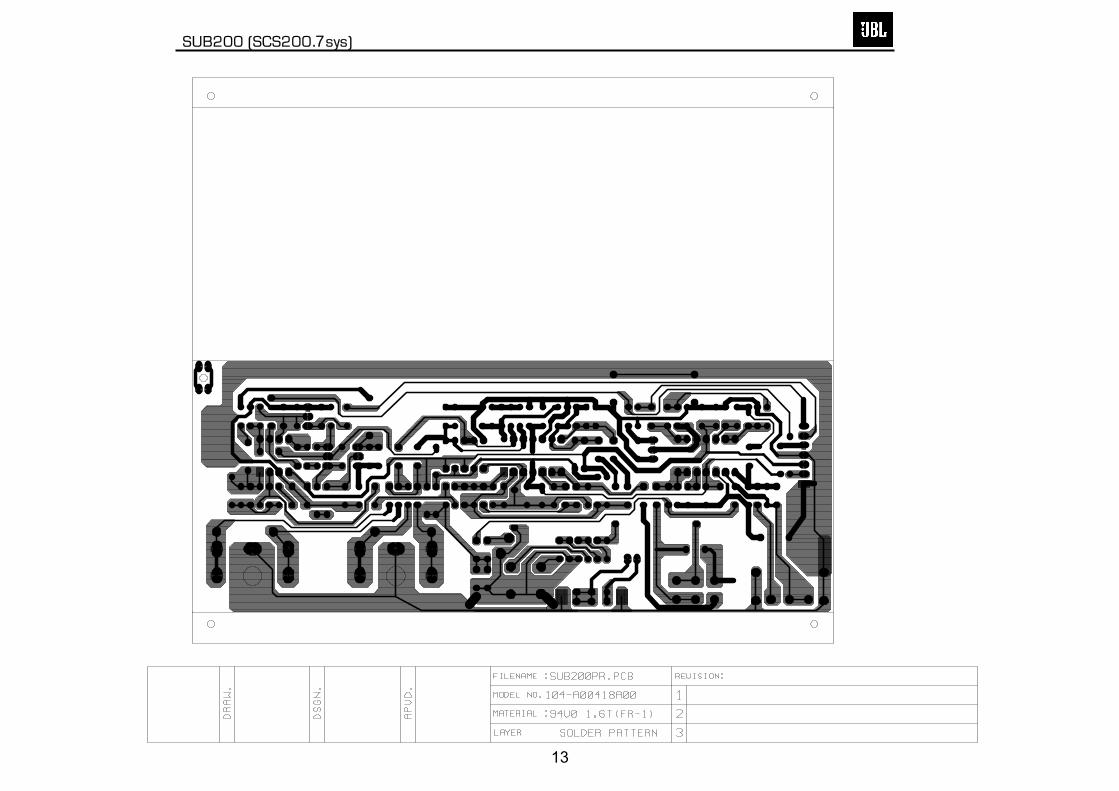
SUB200 (SCS200.7 sys)
230V POWER SUPPLY PCB
17

SUB200 120v Electrical parts List Part Number Description Qty Reference Designator
Main Amp PCB
Resistors
110-14472j26 Resistor 4.7K 1/4W ±5% 26mm 2 R147,150110-14681j26 Resistor 680Ω 1/4W ±5% 26mm 2 R148,151110-16101j26 Resistor10 0Ω 1/6W ±5%CF 26mm 1 R120110-16102j26 Resistor 1K 1/6W ±5% CF 26mm 1 R124110-16103j26 Resistor 10K 1/6W ±5% CF 26mm 1 R134110-16105j26 Resistor 1M 1/6W ±5% CF 26mm 1 R143110-16123j26 Resistor 12K 1/6W ±5% CF 26mm 2 R135,139110-16152j26 Resistor 1.5K 1/6W ±5% CF 26mm CF 6 R103,123,136,137,141,142110-16153j26 Resistor 15K 1/6W ±5% CF 26mm 4 R118,145,152,154110-16154j26 Resistor 150K 1/6W ±5% CF 26mm 1 R131110-16181j26 Resistor 18Ω 1/6W ±5% CF 26mm 2 R11,114110-16182j26 Resistor 1.8K 1/6W ±5% CF 26mm 1 R153110-16223j26 Resistor 22K 1/6W ±5% CF 26mm 3 R128,129,133110-16332j26 Resistor 3.3K 1/6W ±5% CF 26mm 3 R106,107,144110-16392j26 Resistor 3.9K 1/6W ±5% CF 26mm 2 R105,108110-16393j26 Resistor 39K 1/6W ±5% CF 26mm 1 R126110-16470j26 Resistor 47Ω 1/6W ±5%CF 26mm 4 R112,113,115,116110-16471j26 Resistor 470Ω 1/6W ±5% CF 26mm 1 R140110-16472j26 Resistor 4.7K 1/6W ±5% CF 26mm 3 R110,125,130110-16473j26 Resistor 47K 1/6W ±5% CF 26mm 1 R101110-16560j26 Resistor 56Ω 1/6W ±5% CF 26mm 1 R117110-16563j26 Resistor 56K 1/6W ±5% CF 26mm 1 R104110-16682j26 Resistor 6.8K 1/6W ±5% CF 26mm 1 R109110-10821jk2 Resistor 820Ω 1W ±5% 10mm 1 R132110-122r2j15 Resistor 2.2Ω 1/2W ±5% 15mm 1 R127110-20331jk2 Resistor 330Ω 2W ±5% 5mm 2 R146,149113-50r10j10 cement Resistor 0.1Ω 5W ±5% 2 R121,122114-03302m0 semi-fixed Resistor 3K 0.3W 1±20% 1 R138
Capacitors
132-223ja03 mylar capacitor 0.022uF 100V ±5% 2 C123,127135-3107m16 electrolytic 100uF 16V ±20% 1 C110135-4688m50 electrolytic 6800U/50V ±20% D25X45mm 2 C121,122130-2b102k503 disc capacitor 1000p 50V±10% 1 C116130-2f104z503 disc capacitor0.1u 50V+80/ -20% 4 C108.113.115.119130-3f473m503 disc capacitor0.047u 50V±20% 1 C106130-s1101k503 disc capacitor100p 50V SL±10% 2 C139,140132-104J503 mylar capacitor 0.1u50V ±5% 1 C107132-223ja03 mylar capacitor 0.022uF 100V ±5% 4 C124,125,126,128135-3105m50 mylar capacitor 1U 50V ±20% 2 C105,112135-3107m16 mylar capacitor 100uF 16V ±20% 3 C109,117,120135-3226m50 mylar capacitor 22U 50V ±20% 2 C114,118135-3227m10 mylar capacitor 220U 10V ±20% 2 C129,130135-3227m16 mylar capacitor 220U 16V ±20% 1 C111135-3476m25 mylar capacitor 47U 25V ±20% 1 C103
Semiconductors
192-027c1815gr transistor 2SC1815GR NPN 5 Q102,111,112,113,118192-028a1015gr transistor 2SA1015GR PNP 2 Q114,116192-1572n5551 transistor 2N5551 NPN 2 Q103,109192-1582n5401 transistor 2N5401 AI-PNP 350V 500MA TO-92 2 Q104,110197-031n4148 diode 100mA 75V SIGNAL 1N4148 ROHM 4 D101,103,105,108199-15000335 zener diode3.3V 1/2W 52mm 1 D102199-15000625 zener diode 6.2V 1/2W 52mm 2 D106,107199-15001605 zener diode 16V 1/2W 52mm 1 D109190-06m4558d IC OPA 4558D DUAL OP-AMP 1 U101
SUB200 (SCS200.7sys)
18

Part Number Description Qty Reference Designator
Main Amp PCB
192-021tip35c transistor TIP35C NPN 1 Q107192-022tip36c transistor TIP36C PNP 1 Q108192-027c1815gr transistor 2SC1815GR NPN 2 Q101,115192-201d882Y transistor KSD882Y PNP 1 Q117192-202b772y transistor KSB772Y PNP 1 Q119192-991d669a transistor HI-SINCERITY HSD669A NPN 1 Q106192-992b649T transistor HSB649T PNP 1 Q105197-00kb1405 diode 4A500V KBL405 BRIDGE 1 D110197-101n4002 diode IN4002 1 D104
Miscellaneous
193-3m2520 insulator TO-3P 25x20mm 2 for Q107,108162-10202001 wire 26AWC 1007 200mm RED 1171-udhss124d relay 5A 24V UDH-SS124D 1 RY101175-1c07v01 wire connector 7PIN PITCH=2.5mm 1 P101175-1d02v01 wire connector 2PIN PITCH=3.96mm 1 P102175-1d03v01 wire connector 3PIN PITCH=3.96mm 1 P103323-AL-00020 Heat sink 65*32*31 1351-AM03014A094 screw 1352-AM03008D040 screw 4361-FE-00051 transistor holder 1361-NYL-00054 transistor sheet 2
Input/Preamp PCB
Resistors
110-12472j52 Resistor 4.7K 1/2W ±5% CF 52mm 2 R201,202110-16102j26 Resistor 1K 1/6W ±5% CF 26mm 4 R213,214,215,254
110-16103j26 Resistor 10K 1/6W ±5% CF 26mm 14 R209,212,216,217,220,221,222,225,228,226,232,235,240,248
110-16104j26 Resistor 100K 1/6W ±5% CF 26mm 2 R231,266110-16105j26 Resistor 1M 1/6W ±5% CF 26mm 1 R259110-16122j26 Resistor 1.2K 1/6W ±5% CF 26mm 1 R264110-16124j26 Resistor 120K 1/6W ±5% CF 26mm 1 R233110-16151j26 Resistor 150Ω 1/6W ±5% CF 26mm 1 R253110-16153j26 Resistor 15K 1/6W ±5% CF 26mm 1 R234110-16154j26 Resistor 150K 1/6W ±5% CF 26mm 5 R203,204,205,206,252110-16183j26 Resistor 18K 1/6W ±5% CF 26mm 2 R262,227110-16205j26 Resistor 2M 1/6W ±5% CF 26mm 1 R257110-16223j26 Resistor 22K 1/6W ±5% CF 26mm 4 R238,247,250,255110-16273j26 Resistor 27K 1/6W ±5% CF 26mm 2 R223,237110-16333j26 Resistor 33K 1/6W ±5% CF 26mm 1 R249110-16472j26 Resistor 4.7K 1/6W ±5% CF 26mm 4 R200,207,258,260110-16473j26 Resistor 47K 1/6W ±5% CF 26mm 2 R219,251110-16512j26 Resistor 5.1K 1/6W ±5% CF 26mm 4 R210,211,229,230110-16513j26 Resistor 51K 1/6W ±5% CF 26mm 1 R224115-h503a104 Variable resistor D16 50K/1 A LEVEL 1 VR201
Capacitors
130-2b221k503 disc capacitor 220P 50V ± 10% 12 C204,205,207,208,210,211,212,214,220,230,200,249130-2f104z503 disc capacitor 0.1U 50V +80/-20% 7 C232,242,244,245,246,252,254130-sl470k503 disc capacitor 47P 50V ± 10% 1 C229132-103j503 electolytic 0.01U 50V ± 5% 2 C223,224132-104j503 electolytic 0.1U 50V ± 5% 3 C218,221,222132-223ja03 electolytic 0.22uF 100V ± 5% C215132-473j503 electolytic 0.047U 50V ± 5% 2 C216,217135-3105m50 electolytic 1U 50V ± 20% 1 C228135-3106m50 electolytic 10uF 50V ± 20% 10 C201,202,206,213,219,231,241,243,251,253135-3107m16 electolytic 100uF 16V ± 20% 2 C233,234
SUB200 (SCS200.7sys)
19

Part Number Description Qty Reference Designator
Input/Preamp PCB
135-3226m50 electolytic 22U 50V ± 20% 1 C225
Semiconductors
192-027c1815gr transistor 2SC1815GR NPN 3 Q201,206,207197-031n4148 diode 100mA 75V SIGNAL 1N4148 ROHM 11 D201,202,203,204,205,206,207,208,211,212,214199-15000335 zener diode 3.3V 1/2W 52mm 1 D213190-06m4558d I.C OPA 4558D DUAL OP-AMP 1 U203190-16t1074cn I .C TL074cm QUAD OP-AMP 2 U201,202195-10204hgw LED 204HGW 3c 1 D209
Miscellaneous
162-50159201 WIRE ASS'Y 2PIN 150mm 1 for D209174-0rca326p JACK RCA-326 3 input 1 JK202174-2psz406g1 JACK S-8071 1 JK203174-2psz406g2 SPK JK 4PIN S-8072 1 JK203
Limiter PCB
110-16103j26 Resistor 10K 1/6W ±5% CF 26mm 8 R301,303,304,308,309,314,340,344110-16183j26 Resistor 18K 1/6W ±5% CF 26mm 1 R302110-16223j26 Resistor 22K 1/6W ±5% CF 26mm 2 R310,312110-16273j26 Resistor 27K 1/6W ±5% CF 26mm 1 R341110-16333j26 Resistor 33K 1/6W ±5% CF 26mm 1 R305110-16472j26 Resistor 4.7K 1/6W ±5% CF 26mm 2 R342,343110-16474j26 Resistor 470K 1/6W ±5% CF 26mm 1 R307110-16751j26 Resistor 750Ω 1/6W ±5% CF 26mm 2 R311,313110-16755j26 Resistor 7.5M 1/6W ±5% CF 26mm 1 R306130-2f104z503 disc capacitor 0.1u 50V +80/-20% 2 C305,306132-103j503 mylar capacitor 0.01U 50V ± 5% 2 C302,303135-3226m50 electolytic 22U 50V ± 20% 2 C301,340135-3476m25 electolytic 47U 25V ± 20% 1 C304192-027c1815gr transistor 2SC1815GR NPN 2 Q301,302197-031n4148 diode 100mA 75V SIGNAL 1N4148 2 D301,302162-50289001 wire CABLE ASS'Y280mm AWG26 1175-9F40HR2 wire connector 40PIN PITCH=2.54mm HR2*40 0.15 P301190-16tl074cn IC TL074CN ST 1 U301
MISCELLANEOUS
130-3f472md00 disc capacitor 4700p 400V ± 20% 1 On Power Switch123-14j70d Ferrite Core U-16.3*8.2*13 1150-e8604107 Power Trans EI-86 60HZ 120V TT086996580 1 T1152-u602015 LineCord SVT FT-2 6FT 1154-u25006t0 Fuse 2.5A 250V 20mm 1155-520020 Fuse Holder R3-11 1162-10082007 WIRE RED 18AWG 80mm 8mm#1015 1162-50652003 WIRE 650mm RED=205# 0.5T BLK=110# 0.5T 1163-11009 wire tie 100mm 2176-wjcel wire connector Pin CE-1 1180-prf1003S switch ROCK RF-1003-BB2-OHA 1 SW100302-AL-00406-0VC Alu. Panel 1306-ABS-00177 Rear cover 1311-ABS-00028 Plastic knob 1302-RUB-00033 Rubber cusion 4323-AL-00141 Heat sink 1333-EVA-00783 EVA (Gasket) 2333-EVA-00807 EVA (Gasket) 2333-EVA-00826 EVA (Gasket) 2333-EVA-00835 EVA (Gasket) 2335-NYL-00002 Cable ring 2
SUB200 (SCS200.7sys)
20

Part Number Description Qty Reference Designator
MISCELLANEOUS
337-CU-00101 Rubber sheet 1350-EM04012D024 Screw 4351-AM03008A079 Screw 6351-BM03012A088 Screw 1351-HM04016A218 Screw 4352-AM03008D040 Screw 8352-AM03010D065 Screw 5354-GM04002 Screw nut 4361-FE-00051 IC holder 1362-FE-00013 PCB holder 2
SUB200 (SCS200.7sys)
21

SUB200 230v Electrical parts List Part Number Description Qty Reference Designator
Input/Preamp PCBs
Resistors
110-12472j52 Resistor 4.7K 1/2W ±5% CF 52mm 2 R20,202110-16102j26 Resistor 1K 1/6W ±5% CF 26mm 4 R213,214,215,254
110-16103j26 Resistor 10K 1/6W ±5% CF 26mm 14 R209,212,216,217,220,221,222,225,228,226,232,235, 240,248
110-16104j26 Resistor 100K 1/6W ±5% CF 26mm 2 R231,266110-16105j26 Resistor 1M 1/6W ±5% CF 26mm 1 R259110-16122j26 Resistor 1.2K 1/6W ±5% CF 26mm 1 R264110-16124j26 Resistor 120K 1/6W ±5% CF 26mm 1 R233110-16151j26 Resistor 150Ω 1/6W ±5% CF 26mm 1 R253110-16153j26 Resistor 15K 1/6W ±5% CF 26mm 1 R234110-16154j26 Resistor 150K 1/6W ±5% CF 26mm 5 R203,204,205,206,252110-16183j26 Resistor 18K 1/6W ±5% CF 26mm 2 R262,227110-16205j26 Resistor 2M 1/6W ±5% CF 26mm 1 R257110-16223j26 Resistor 22K 1/6W ±5% CF 26mm 4 R238,247,250,255110-16273j26 Resistor 27K 1/6W ±5% CF 26mm 2 R223,237110-16333j26 Resistor 33K 1/6W ±5% CF 26mm 1 R249110-16472j26 Resistor 4.7K 1/6W ±5% CF 26mm 4 R200,207,258,260110-16473j26 Resistor 47K 1/6W ±5% CF 26mm 2 R219,251110-16512j26 Resistor 5.1K 1/6W ±5% CF 26mm 4 R210,211,229,230110-16513j26 Resistor 51K 1/6W ±5% CF 26mm 1 R224115-h503a104 variable resistor D16 50K/1 A 1 VR201
Capacitors
130-2b221k503 disc capacitor 220P 50V ± 10% 12 C204,205,207,208,210,211,212,214,220,230,200,249130-2f104z503 disc capacitor 0.1U 50V +80/-20% 7 C232,242,244,245,246,252,254130-sl470k503 disc capacitor 47P 50V ± 10% 1 C229132-103j503 Electrolytic 0.01U 50V ± 5% 2 C223,224132-104j503 Electrolytic 0.1U 50V ± 5% 3 C218,221,222132-223ja03 Electrolytic 0.02uF100V ± 5% 1 C215132-473j503 Electrolytic 0.047uF 50V ± 5% 2 C216,217135-3105m50 Electrolytic 1U 50V ± 20% 1 C228135-3106m50 Electrolytic 10uF 50V ± 20% 10 C201,202,206,213,219,231,241,243,251,253135-3107m16 Electrolytic 100uF 16V ± 20% 2 C233,234135-3226m50 Electrolytic 22U 50V ± 20% 1 C225
Semiconductors
192-027c1815gr transistor 2SC1815GR NPN 3 Q201,206,207197-031n4148 diode 100mA 75V SIGNAL 1N4148 ROHM 11 D201,202,203,204,205,206,207,208,211,212,214199-15000335 zener diode 3.3V 1/2W 52mm 1 D213190-06m4558d I.C OPA 4558D DUAL OP-AMP 1 U203190-16t1074cn I .C TL074cm QUAD OP-AMP 2 U201,202195-10204hgw LED 204HGW 3c 1 D209
Miscellaneous
162-50159201 WIRE ASS'Y 2PIN 150mm 1 D209174-0rca326p JACK RCA-326 1 JK202174-2psz406g1 JACK S-8071 1 JK203174-2psz406g2 SPK JK 4PIN S-8072 1 JK203
Main Amp PCB
Resistors
110-14560j26 Resistor 56Ω 1/4W ±5% CF 26mm 1 R117
SUB200 (SCS200.7 sys)
22

Part Number Description Qty Reference Designator
Main Amp PCB
110-14680j26 Resistor 68Ω 1/4W ±5% CF 26mm 2 R146,149110-16101j26 Resistor 100Ω 1/6W ±5% CF 26mm 1 R120110-16102j26 Resistor 1K 1/6W ±5% CF 26mm 2 R124,166110-16103j26 Resistor 10K 1/6W ±5% CF 26mm 1 R133110-16104j26 Resistor 100K 1/6W ±5% CF 26mm 2 R163,164110-16105j26 Resistor 1M 1/6W ±5% CF 26mm 1 R143110-16123j26 Resistor 12K 1/6W ±5% CF 26mm 4 R135,139,165,134110-16152j26 Resistor 1.5K 1/6W ±5% CF 26mm 7 R103,123,136,137,141,142,153110-16153j26 Resistor 15K 1/6W ±5% CF 26mm 4 R118,145,152,154110-16154j26 Resistor 150K 1/6W ±5% CF 26mm 1 R131110-16181j26 Resistor 180Ω 1/6W ±5% CF 26mm 2 R111,114110-16223j26 Resistor 22K 1/6W ±5% CF 26mm 6 R128,129,155,156,158,160110-16332j26 Resistor 3.3K 1/6W ±5% CF 26mm 3 R106,107,144110-16392j26 Resistor 3.9K 1/6W ±5% CF 26mm 2 R105,108110-16393j26 Resistor 39K 1/6W ±5% CF 26mm 1 R126110-16470j26 Resistor 47Ω 1/6W ±5% CF 26mm 4 R112,113,115,116110-16471j26 Resistor 470Ω 1/6W ±5% CF 26mm 3 R140,161,162110-16472j26 Resistor 4.7K 1/6W ±5% CF 26mm 4 R200,207,258,260110-16473j26 Resistor 47K 1/6W ±5% CF 26mm 1 R101110-16563j26 Resistor 56K 1/6W ±5% CF 26mm 1 R104110-16681j26 Resistor 680Ω 1/6W ±5% CF 26mm 2 R148,151110-16682j26 Resistor 6.8K 1/6W ±5% CF 26mm 1 R109110-10821jk2 resistor 820Ω 1W ±5% 10mm 1 R132110-122r2j15 resistor 2.2Ω 1/2W ±5% 15mm 1 R127110-20331jk2 resistor 330Ω 2W ±5% 5mm 2 R146,149113-50r10j10 cement resistor 0.1Ω 5W ±5% 2 R121,122114-03302m0 semi-fixed resistor 3K 0.3 ±20% 1 R138
Capacitors
135-4478m35 electrolytic 4700uf 35v ±20% 1 121,122135-4478m50 electrolytic 4700uf 50v ±20% 2 C133,134130-2b102k503 disc capacitor 1000P 50V ± 10% 2 C116,141130-2f104z503 disc capacitor 0.1U 50V +80/-20% 6 C108,113,115,119,137,138130-3f473m503 disc capacitor 0.047U 50V ± 20% 1 C106130-sl101k503 disc capacitor 100P 50V SL ± 10% 3 C139,140,104132-104j503 Electrolytic 0.1U 50V ± 5% 1 C107132-223ja03 Electrolytic 0.022uF 50V ± 5% 8 C124,125,126,128,123,127,131,132135-3105m50 Electrolytic 1U 50V ± 20% 2 C105,112135-3107m16 Electrolytic 100uF 16V ± 20% 4 C109,117,120,110135-3226m50 Electrolytic 22U 50V ± 20% 2 C114,118135-3227m10 Electrolytic 220U 10V ± 20% 2 C129,130135-3227m16 Electrolytic 220U 16V ± 20% 1 C111135-3476m25 Electrolytic 47U 25V ± 20% 1 C103135-3107-m50 Capacitor 100U 50V 2 C135, 136
Semiconductors
192-027c1815gr Transistor 2SC1815GR NPN 7 Q101,102,111,112,113,115,118,123,126192-027c2235y Transistor 2SC2235Y NPN 1 Q121192-028a1015gr Transistor 2SA1015GR PNP 4 Q114,116,122,127192-028a965y Transistor 2SA965Y PNP 1 Q125192-1572n5551 Transistor 2N5551 NPN 2 Q103,109192-1582n5401 92 2 Q104,110192-992b649T Transistor HSB649T PNP 1 Q105192-021tip35c Transistor TIP35C NPN 1 Q107192-022tip36c Transistor TIP36C PNP 1 Q108192-161tip41c Transistor TIP41C NPN SGS 1 Q124192-162tip42c Transistor TIP42C NPN SGS 1 Q120192-201b882Y transistor KSD882Y NPN 1 Q117192-201b772Y transistor KSB772Y PNP 1 Q119192-991d669a Transistor HI-SINCERITY HSD669A NPN 1 Q106
SUB200 (SCS200.7 sys)
23

Part Number Description Qty Reference Designator
Main Amp PCB
197-031n4148 diode 100mA 75V SIGNAL 1N4148 ROHM 7 D101,103,105,108,113,114,116199-15000335 zener diode 3.3V 1/2W 52mm 1 D102199-15000625 zener diode 6.2V 1/2W 52mm 2 D106,107199-15001605 zener diode 16V 1/2W 52mm 1 D109197-00kb1405 diode 4A500V KBL405 BRIDGE 2 D110,115197-101n4002 diode IN4002 1 D104197-101n5402 diode IN5402 2 D111,112190-06m4558d IC OPA 4558D Dual Op-Amp 1 U101
Miscellaneous
323-AL-00020 HEAT SINK 65*32*31 1351-AM03014A094 Screw M3*14 1352-AM03008D040 Screw ¢3*8 4361-FE-00051 diode holder 14.2*8.0*5.2t=1.6mm 1361-NYL-00054 Insulated sheet 2193-3m2520 insulator TO-3P 25x20mm 2 for Q107,108171-udhss124d relay 5A 24V UDH-SS124D 1 RY101162-10202001 wire 26AWC 1007 200mm RED 3m 1175-1c07v01 wire connector 7PIN PITCH=2.5mm 1 P101175-1d02v01 wire connector 2PIN PITCH=3.96mm 1 P102175-1d05v01 wire connector 5PIN PITCH=3.96mm 1 P103
Limiter PCB
110-16103j26 Resistor 10K 1/6W ±5% CF 26mm 8 R301,303,304,308,309,314,340,344,110-16183j26 Resistor 18K 1/6W ±5% CF 26mm 1 R302110-16223j26 Resistor 22K 1/6W ±5% CF 26mm 2 R310,312110-16273j26 Resistor 27K 1/6W ±5% CF 26mm 1 R341110-16333j26 Resistor 33K 1/6W ±5% CF 26mm 1 R305110-16472j26 Resistor 4.7K 1/6W ±5% CF 26mm 2 R342,343110-16474j26 Resistor 470K 1/6W ±5% CF 26mm 1 R307110-16751j26 Resistor 750Ω 1/6W ±5% CF 26mm 2 R311,313110-16755j26 Resistor 7.5k 1/6W ±5% CF 26mm 1 R306130-2f104z503 disc capacitor 0.1u 50V +80/-20% 2 C305,306132-103j503 mylar capacitor 0.01U 50V ± 5% 2 C302,303135-3226m50 Electrolytic 22U 50V ± 20% 2 C301,340135-3476m25 Electrolytic 47U 25V ± 20% 1 C304192-027c1815gr SMD Transistor 2SC1815TRP 2 Q301,302197-031n4148 diode 100mA 75V SIGNAL 1N4148 ROHM 2 D301,302162-50289001 wire CABLE ASS'Y280mm AWG26 1175-9f40hr2 wire connector 40PIN PITCH=2.54mm
HR2*40 0.15 P301190-16tl074cn IC TL047CN ST 1 U301
MISCELLANEOUS
123-14j70d Ferrite Core U-16.3*8.2*13 1132-104kb70 mylar capacitor 0.1uF 275V ±10% VDE 1 POWER SW
150-e8604106Power Transformer EI-86 230V/50HZ TT0869803320 1
152-v602026 Power cord SP-021A 6FT VDE 1154-v12506t0 Fuse TSD 1.25A 250V VDE 1 FS101155-520020 Fuse Holder R3-11 1162-10082007 WIRE RED 18AWG 80mm 8mm#1015 1162-50652003 WIRE 650mm RED=205# 0.5T 1176-wjcel wire connector Pin CE-1 1180-prf1003s switch ROCK RF-1003-BB2-OHA 1 SW101193-2m1813 insulator TO-220 18*13mm 2 Q120,124350-EM04012D024 Screw 4¢*12 4351-HM04016A218 Screw M4*16 4351-BM03012A088 Screw M3*12 1351-AM03008A079 Screw M3*8 6
SUB200 (SCS200.7 sys)
24

Part Number Description Qty Reference Designator
MISCELLANEOUS
352-AM03010D065 Screw ¢3*10 5352-AM03008D040 Screw ¢3*8 8354-GM04002 Screw M4 4361-FE-00004 IC HOLDER 26.9*12*1.4T 1362-FE-00013 PCB holder 2311-ABS-00028 Plastic volume knob 1335-NYL-00002 Wire knob 2333-EVA-00783 EVA W 198*12*2.0T 2333-EVA-00807 EVA L 274*12*2.0T 2333-EVA-00826 EVA W 198*12*1.0T 2333-EVA-00835 EVA L 274*12*1.0T 2320-RUB-00033 Rubber sheet 25*21*4t 4337-CU-00101 Copper sheet 65L*50W 1323-AL-00141 HEAT SINK 117.5*71.5*25 1302-AL-00405-0VC Aluminum panel 200*300*2.5T 1306-ABS-00206 Rear Plastic cover 198*298*102H 1
SUB200 (SCS200.7 sys)
25

SUB200 (SCS200.7sys)
26

R306
SUB200 (SCS200.7sys) 120V SCHEMATICS PAGE 1
27

SUB200 (SCS200.7sys)
STANDBY DELAY Adjustment Procedure for R138: Use DC voltmeter attached to R140, adjust R138 until the meter reads 510mV (+/-2mV) (for 120v model) 460mV (+/-2mV) (for 230v model) then use "LOCTITE" to fix R138.
120V SCHEMATICS PAGE 2
28

SUB200 (SCS200.7 sys) 230V SCHEMATICS PAGE 1
29

SUB200 (SCS200.7 sys) 230V SCHEMATICS PAGE 2
30

SCS200.7 Outer Carton(120v) 402-000-01821
Warranty Card405-000-00258
(120v) Owner’s Manual406-000-00956
Speaker Wire 20 Feet (3)166-020F84XX
Speaker Wire 40 Feet (4)166-040F84XX
Speaker Wire 15 Feet (2)166-015F84XX
RCA Cable 15 Feet166-015F011
Floor Stand Adapter (6)325-ABS-00436
Wall-Mount Bracket (Sats & Center) (7)326-ABS-05013
Center Shelf Stand398-ABS-05043
Sat Shelf Stand (6)398-ABS-05041
Hardware Bag A371-000-05019
Hardware Bag B371-000-05027
Screw (6)354-GC250703
SCS200.7 system Packaging
(230v) Owner’s Manual406-000-00954
431-000-05030
Subwoofer Packing431-000-05032
Sat/Center Packing
Sat/Center Packing431-000-05030
Subwoofer Packing431-000-05032 SCS200.7 Outer Carton
(230v) 402-000-05078
SUB200 (SCS200.7 sys)
31