Embed Size (px)
Citation preview
172-65409A-01 (SP-COSR-16) 19 October 2021
Manufacturer
881 Nagasuna, Noguchi, Kakogawa, Hyogo, 675-8511, Japan
Tel: [81]-(0)79-422-1122 Fax: [81]-(0)79-422-0112
Copyright © 2021 by TLV CO., LTD. All rights reserved
Surplussing Valve
SP-COSR-16
172-65409A-01 (SP-COSR-16) 19 Oct 2021
1
Contents
Introduction ....................................................................... 1
Safety Considerations ....................................................... 2
Piping ................................................................................ 4
Configuration ..................................................................... 6
Adjustment ........................................................................ 7
Disassembly and Inspection ............................................. 8
Regular Inspection and Maintenance .............................. 13
Troubleshooting .............................................................. 13
Specifications .................................................................. 16
TLV EXPRESS LIMITED WARRANTY ........................... 18
Introduction
Thank you for purchasing the TLV surplussing valve.
This product has been thoroughly inspected before being shipped from the factory.
When the product is delivered, before doing anything else, check the specifications
and external appearance to make sure nothing is out of the ordinary. Also be sure to
read this manual carefully before use and follow the instructions to be sure of using
the product properly.
If detailed instructions for special order specifications or options not contained in this
manual are required, please contact TLV for full details.
This instruction manual is intended for use with the model(s) listed on the front cover.
It is necessary not only for installation but for subsequent maintenance,
disassembly/reassembly and troubleshooting. Please keep it in a safe place for
future reference.
172-65409A-01 (SP-COSR-16) 19 Oct 2021
2
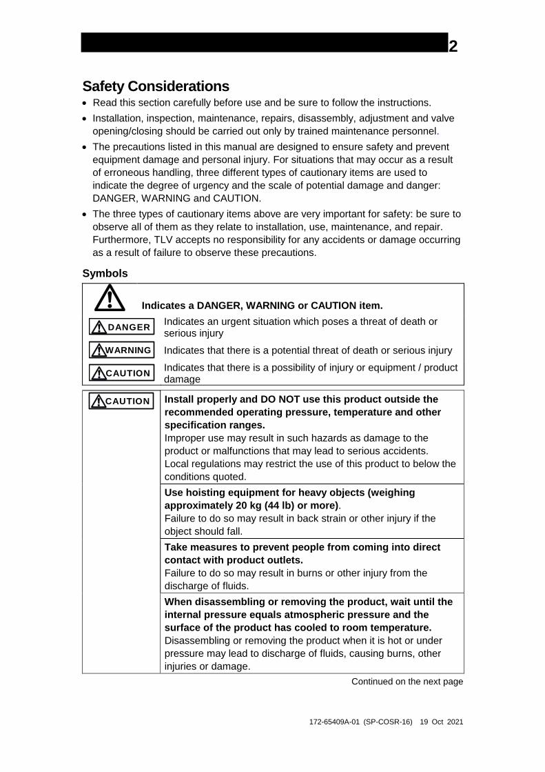
Safety Considerations Read this section carefully before use and be sure to follow the instructions.
Installation, inspection, maintenance, repairs, disassembly, adjustment and valve
opening/closing should be carried out only by trained maintenance personnel.
The precautions listed in this manual are designed to ensure safety and prevent
equipment damage and personal injury. For situations that may occur as a result
of erroneous handling, three different types of cautionary items are used to
indicate the degree of urgency and the scale of potential damage and danger:
DANGER, WARNING and CAUTION.
The three types of cautionary items above are very important for safety: be sure to
observe all of them as they relate to installation, use, maintenance, and repair.
Furthermore, TLV accepts no responsibility for any accidents or damage occurring
as a result of failure to observe these precautions.
Symbols
Indicates a DANGER, WARNING or CAUTION item.
DANGER
Indicates an urgent situation which poses a threat of death or serious injury
WARNING
Indicates that there is a potential threat of death or serious injury
CAUTION
Indicates that there is a possibility of injury or equipment / product damage
CAUTION
Install properly and DO NOT use this product outside the
recommended operating pressure, temperature and other
specification ranges.
Improper use may result in such hazards as damage to the
product or malfunctions that may lead to serious accidents.
Local regulations may restrict the use of this product to below the
conditions quoted.
Use hoisting equipment for heavy objects (weighing
approximately 20 kg (44 lb) or more).
Failure to do so may result in back strain or other injury if the
object should fall.
Take measures to prevent people from coming into direct
contact with product outlets.
Failure to do so may result in burns or other injury from the
discharge of fluids.
When disassembling or removing the product, wait until the
internal pressure equals atmospheric pressure and the
surface of the product has cooled to room temperature.
Disassembling or removing the product when it is hot or under
pressure may lead to discharge of fluids, causing burns, other
injuries or damage.
Continued on the next page
172-65409A-01 (SP-COSR-16) 19 Oct 2021
3
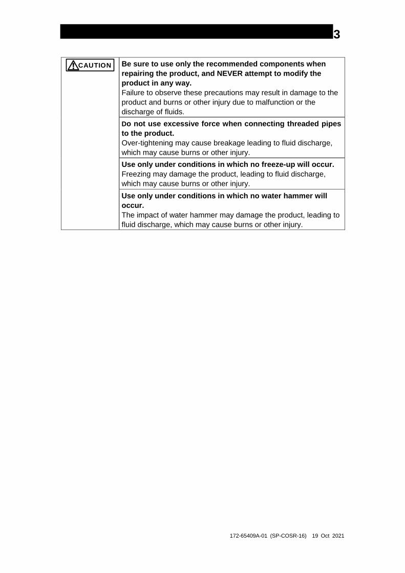
CAUTION
Be sure to use only the recommended components when
repairing the product, and NEVER attempt to modify the
product in any way.
Failure to observe these precautions may result in damage to the
product and burns or other injury due to malfunction or the
discharge of fluids.
Do not use excessive force when connecting threaded pipes
to the product.
Over-tightening may cause breakage leading to fluid discharge,
which may cause burns or other injury.
Use only under conditions in which no freeze-up will occur.
Freezing may damage the product, leading to fluid discharge,
which may cause burns or other injury.
Use only under conditions in which no water hammer will
occur.
The impact of water hammer may damage the product, leading to
fluid discharge, which may cause burns or other injury.
172-65409A-01 (SP-COSR-16) 19 Oct 2021
4
Piping
Install the product as follows:
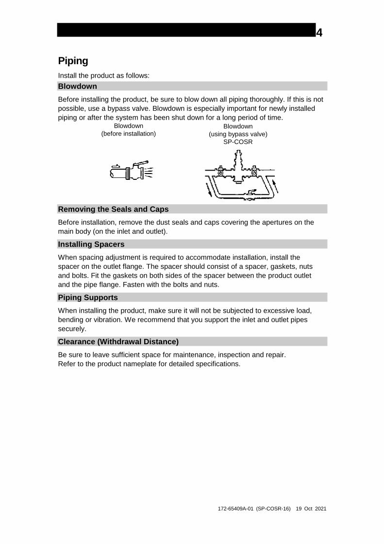
Blowdown
Before installing the product, be sure to blow down all piping thoroughly. If this is not
possible, use a bypass valve. Blowdown is especially important for newly installed
piping or after the system has been shut down for a long period of time. Blowdown
(before installation)Blowdown
(using bypass valve)
SP-COSR
Removing the Seals and Caps
Before installation, remove the dust seals and caps covering the apertures on the
main body (on the inlet and outlet).
Installing Spacers
When spacing adjustment is required to accommodate installation, install the
spacer on the outlet flange. The spacer should consist of a spacer, gaskets, nuts
and bolts. Fit the gaskets on both sides of the spacer between the product outlet
and the pipe flange. Fasten with the bolts and nuts.
Piping Supports
When installing the product, make sure it will not be subjected to excessive load,
bending or vibration. We recommend that you support the inlet and outlet pipes
securely.
Clearance (Withdrawal Distance)
Be sure to leave sufficient space for maintenance, inspection and repair.
Refer to the product nameplate for detailed specifications.
172-65409A-01 (SP-COSR-16) 19 Oct 2021
5
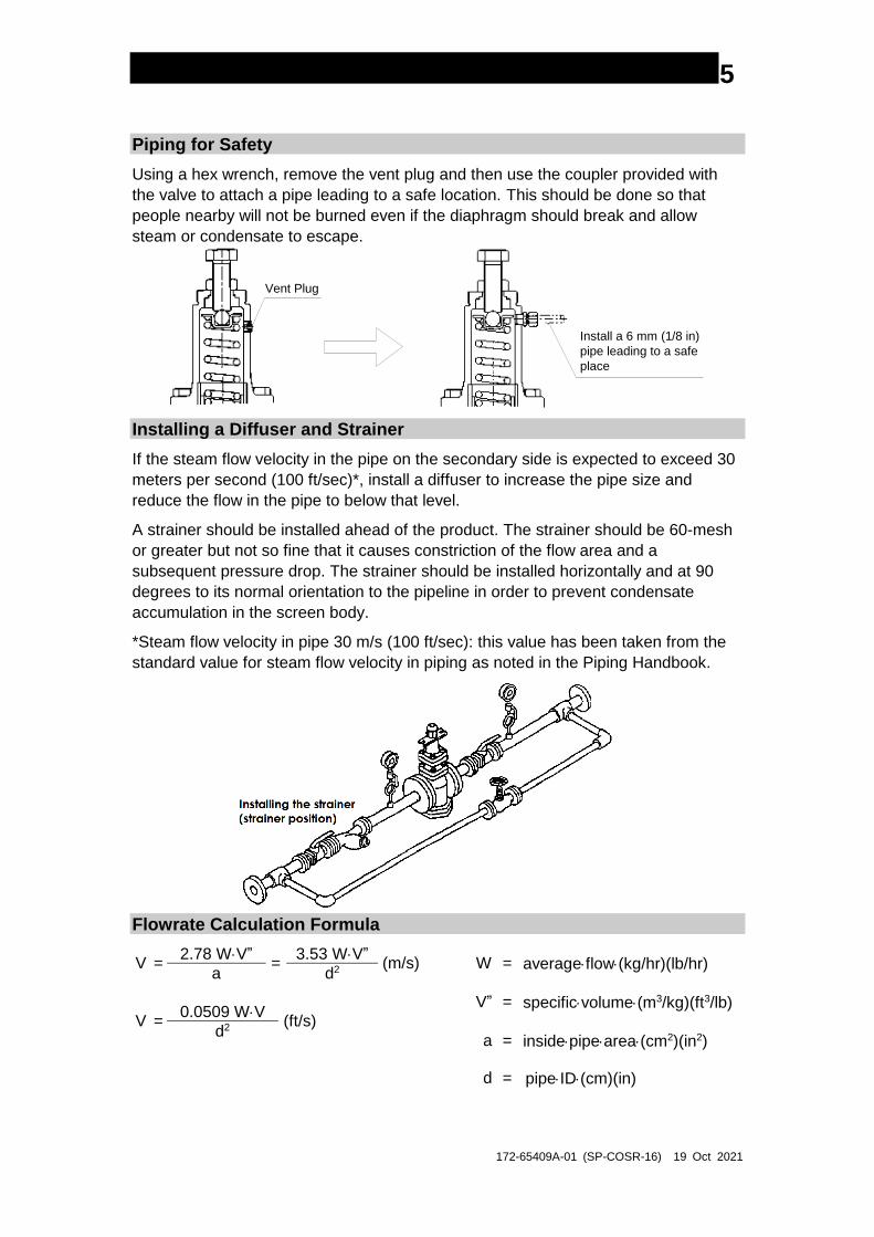
Piping for Safety
Using a hex wrench, remove the vent plug and then use the coupler provided with
the valve to attach a pipe leading to a safe location. This should be done so that
people nearby will not be burned even if the diaphragm should break and allow
steam or condensate to escape.
Vent Plug
Install a 6 mm (1/8 in)
pipe leading to a safe
place
Installing a Diffuser and Strainer
If the steam flow velocity in the pipe on the secondary side is expected to exceed 30
meters per second (100 ft/sec)*, install a diffuser to increase the pipe size and
reduce the flow in the pipe to below that level.
A strainer should be installed ahead of the product. The strainer should be 60-mesh
or greater but not so fine that it causes constriction of the flow area and a
subsequent pressure drop. The strainer should be installed horizontally and at 90
degrees to its normal orientation to the pipeline in order to prevent condensate
accumulation in the screen body.
*Steam flow velocity in pipe 30 m/s (100 ft/sec): this value has been taken from the
standard value for steam flow velocity in piping as noted in the Piping Handbook.
Flowrate Calculation Formula
V = 2.78 WV”
= 3.53 WV”
(m/s) W = averageflow(kg/hr)(lb/hr) a d2
V” = specificvolume(m3/kg)(ft3/lb)
V = 0.0509 WV
(ft/s)
d2 a = insidepipearea(cm2)(in2)
d = pipeID(cm)(in)
172-65409A-01 (SP-COSR-16) 19 Oct 2021
6
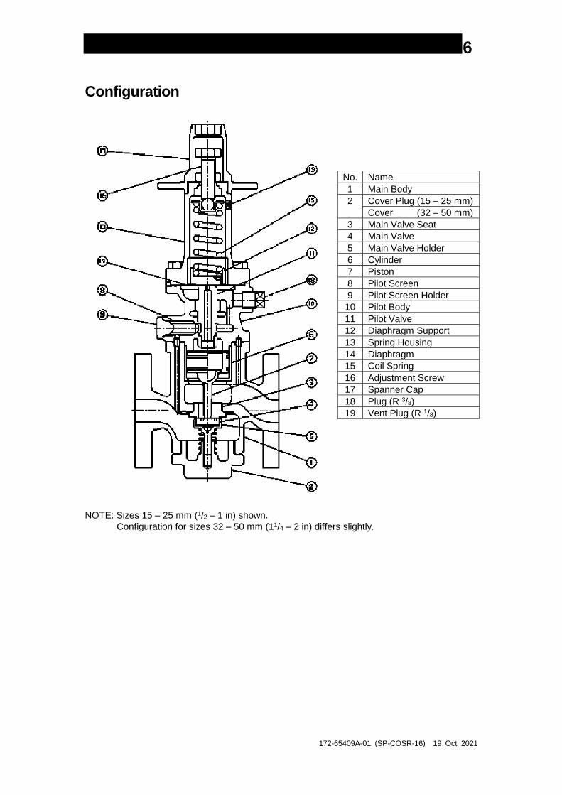
Configuration
No. Name
1 Main Body
2 Cover Plug (15 – 25 mm)
Cover (32 – 50 mm)
3 Main Valve Seat
4 Main Valve
5 Main Valve Holder
6 Cylinder
7 Piston
8 Pilot Screen
9 Pilot Screen Holder
10 Pilot Body
11 Pilot Valve
12 Diaphragm Support
13 Spring Housing
14 Diaphragm
15 Coil Spring
16 Adjustment Screw
17 Spanner Cap
18 Plug (R 3/8)
19 Vent Plug (R 1/8)
NOTE: Sizes 15 – 25 mm (1/2 – 1 in) shown.
Configuration for sizes 32 – 50 mm (11/4 – 2 in) differs slightly.
172-65409A-01 (SP-COSR-16) 19 Oct 2021
7
Adjustment
The product must be properly adjusted for protection of the steam-using equipment
against water hammer.
1. On newly installed piping or after the system has been shut down for a long period
of time, use the bypass valve to blow out the pipes thoroughly. Be especially
careful that no condensate and rust, etc. is left in the steam-using equipment.
2. Make sure that the bypass valve and the shut-off valves upstream and
downstream of the product are completely closed.
3. The product has been preset to the designated pressure at the factory.
4. Open the shut-off valve on the secondary side all the way and then open the shut-
off valve on the primary side slightly.
5. After supplying steam to the product, check to make sure that the
product operates properly and there is no leakage from the pipes, etc. Then
closely open the shut-off valve on the primary side all the way.
6. When the set pressure must be readjusted, use the following procedure.
7. Open the shut-off valve on the secondary side all the way, then open the shut-off
valve on the primary side slightly.
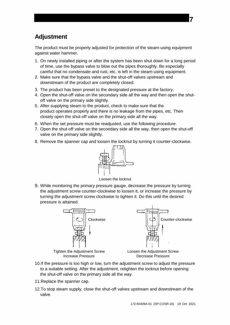
8. Remove the spanner cap and loosen the locknut by turning it counter-clockwise.
Loosen the locknut
9. While monitoring the primary pressure gauge, decrease the pressure by turning
the adjustment screw counter-clockwise to loosen it, or increase the pressure by
turning the adjustment screw clockwise to tighten it. Do this until the desired
pressure is attained.
Tighten the Adjustment Screw
Increase Pressure Loosen the Adjustment Screw
Decrease Pressure
10.If the pressure is too high or low, turn the adjustment screw to adjust the pressure
to a suitable setting. After the adjustment, retighten the locknut before opening
the shut-off valve on the primary side all the way.
11.Replace the spanner cap.
12.To stop steam supply, close the shut-off valves upstream and downstream of the
valve.
Clockwise Counter-clockwise
172-65409A-01 (SP-COSR-16) 19 Oct 2021
8
Disassembly and Inspection
Disassembling and inspecting the valve once a year can help prevent unexpected
failure. We recommend that you inspect the valve right after operating the system
with newly installed piping or after the system has been out of service for a long
period of time.
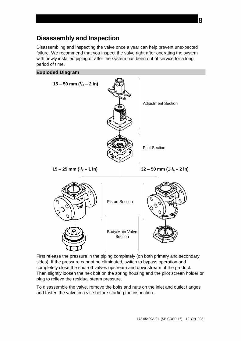
Exploded Diagram
Adjustment Section
Pilot Section
Piston Section
Body/Main Valve
Section
15 – 50 mm (1/2 – 2 in)
15 – 25 mm (1/2 – 1 in) 32 – 50 mm (11/4 – 2 in)
First release the pressure in the piping completely (on both primary and secondary
sides). If the pressure cannot be eliminated, switch to bypass operation and
completely close the shut-off valves upstream and downstream of the product.
Then slightly loosen the hex bolt on the spring housing and the pilot screen holder or
plug to relieve the residual steam pressure.
To disassemble the valve, remove the bolts and nuts on the inlet and outlet flanges
and fasten the valve in a vise before starting the inspection.
172-65409A-01 (SP-COSR-16) 19 Oct 2021
9
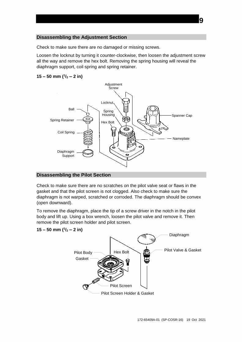
Disassembling the Adjustment Section
Check to make sure there are no damaged or missing screws.
Loosen the locknut by turning it counter-clockwise, then loosen the adjustment screw
all the way and remove the hex bolt. Removing the spring housing will reveal the
diaphragm support, coil spring and spring retainer.
15 – 50 mm (1/2 – 2 in)
Spanner Cap
Nameplate
Coil Spring
Diaphragm
Support
Spring Retainer
Ball
Adjustment Screw
Locknut
SpringHousing
Hex Bolt
Disassembling the Pilot Section
Check to make sure there are no scratches on the pilot valve seat or flaws in the
gasket and that the pilot screen is not clogged. Also check to make sure the
diaphragm is not warped, scratched or corroded. The diaphragm should be convex
(open downward).
To remove the diaphragm, place the tip of a screw driver in the notch in the pilot
body and lift up. Using a box wrench, loosen the pilot valve and remove it. Then
remove the pilot screen holder and pilot screen.
15 – 50 mm (1/2 – 2 in) Diaphragm
Pilot Valve & Gasket
Pilot Screen
Pilot Screen Holder & Gasket
Pilot Body
Gasket
Hex Bolt
172-65409A-01 (SP-COSR-16) 19 Oct 2021
10
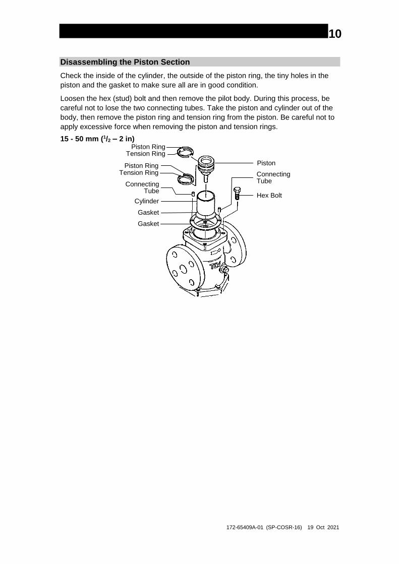
Disassembling the Piston Section
Check the inside of the cylinder, the outside of the piston ring, the tiny holes in the
piston and the gasket to make sure all are in good condition.
Loosen the hex (stud) bolt and then remove the pilot body. During this process, be
careful not to lose the two connecting tubes. Take the piston and cylinder out of the
body, then remove the piston ring and tension ring from the piston. Be careful not to
apply excessive force when removing the piston and tension rings.
15 - 50 mm (1/2 – 2 in) Piston Ring
Tension Ring
Piston RingTension Ring
Hex Bolt
ConnectingTube
Piston
ConnectingTube
Gasket
Cylinder
Gasket
172-65409A-01 (SP-COSR-16) 19 Oct 2021
11
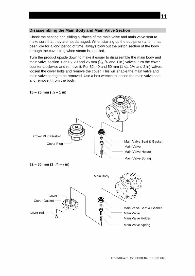
Disassembling the Main Body and Main Valve Section
Check the seating and sliding surfaces of the main valve and main valve seat to
make sure that they are not damaged. When starting up the equipment after it has
been idle for a long period of time, always blow out the piston section of the body
through the cover plug when steam is supplied.
Turn the product upside down to make it easier to disassemble the main body and
main valve section. For 15, 20 and 25 mm (1/2, 3/4 and 1 in.) valves, turn the cover
counter-clockwise and remove it. For 32, 40 and 50 mm (1 1/4, 11/2 and 2 in) valves,
loosen the cover bolts and remove the cover. This will enable the main valve and
main valve spring to be removed. Use a box wrench to loosen the main valve seat
and remove it from the body.
15 – 25 mm (1/2 – 1 in)
Main Valve Seat & Gasket
Main Valve
Main Valve Holder
Main Valve Spring
Cover Plug
Cover Plug Gasket
32 – 50 mm (1 1/4 – 2 in)
Main Valve Seat & Gasket
Main Valve
Main Valve Holder
Main Valve Spring
Main Body
Cover
Cover Gasket
Cover Bolt
172-65409A-01 (SP-COSR-16) 19 Oct 2021
12
Cleaning
Check each section and, if there are no problems, clean and reassemble the parts.
The following parts will require cleaning before reassembly:
Piston and Tension Rings
Diaphragm Support
Inside of Spring Housing (parts that come into contact with the
diaphragm retainer)
Cylinder Pilot Screen Main Valve seat
Pilot Valve Diaphragm Main Valve
Adjustment Screw Piston
Although these parts may be simply rinsed in water, it would be more effective to use
a mild detergent. Carefully wipe components dry after cleaning; especially, the inside
of the spring housing, the diaphragm retainer, adjustment screw and diaphragm.
Assembly
Assemble by following the disassembly procedure in reverse. Use the following
guidelines:
1. PTFE gaskets may be used if they are not damaged, crushed or warped.
2. Apply anti-seize agent to screws and bolts, spring retainer ball and adjustment
screw. On the threads of main valve seats, pilot valves and pilot screen holder
screws, use the anti-seize agent sparingly to make sure it does not come into
contact with other parts.
3. Fasten the bolts one at a time in a diagonally alternate pattern to provide uniform
seating.
4. During assembly, check to make sure the piston moves smoothly.
5. Assemble the piston and tension rings as follows:
- Fit the piston ring to the outside of the tension ring.
- Make sure the ring gaps are opposite one another.
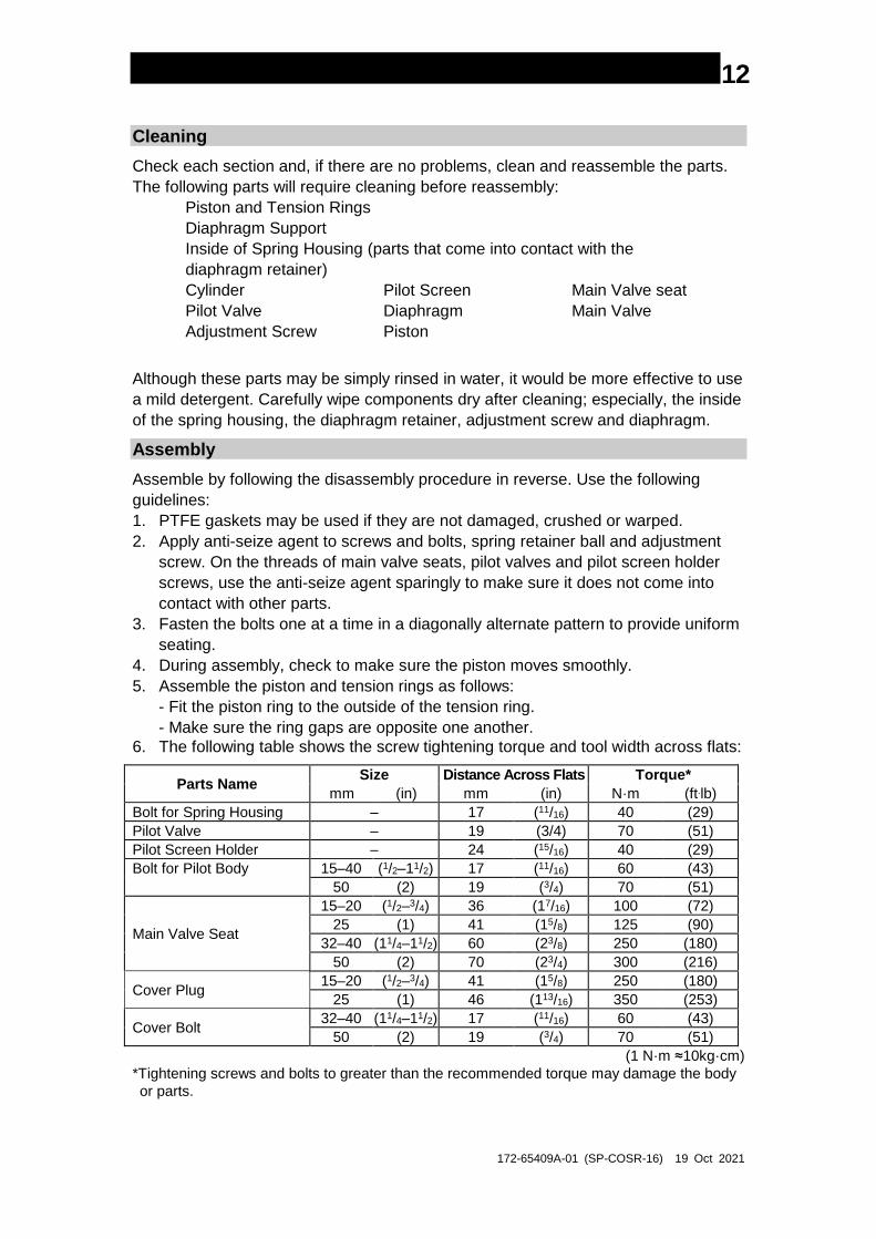
6. The following table shows the screw tightening torque and tool width across flats:
Parts Name Size Distance Across Flats Torque*
mm (in) mm (in) N·m (ft.lb)
Bolt for Spring Housing – 17 (11/16) 40 (29)
Pilot Valve – 19 (3/4) 70 (51)
Pilot Screen Holder – 24 (15/16) 40 (29)
Bolt for Pilot Body 15–40 (1/2–11/2) 17 (11/16) 60 (43)
50 (2) 19 (3/4) 70 (51)
Main Valve Seat
15–20 (1/2–3/4) 36 (17/16) 100 (72)
25 (1) 41 (15/8) 125 (90)
32–40 (11/4–11/2) 60 (23/8) 250 (180)
50 (2) 70 (23/4) 300 (216)
Cover Plug 15–20 (1/2–3/4) 41 (15/8) 250 (180)
25 (1) 46 (113/16) 350 (253)
Cover Bolt 32–40 (11/4–11/2) 17 (11/16) 60 (43)
50 (2) 19 (3/4) 70 (51)
(1 N·m ≈10kg·cm)
*Tightening screws and bolts to greater than the recommended torque may damage the body
or parts.
172-65409A-01 (SP-COSR-16) 19 Oct 2021
13
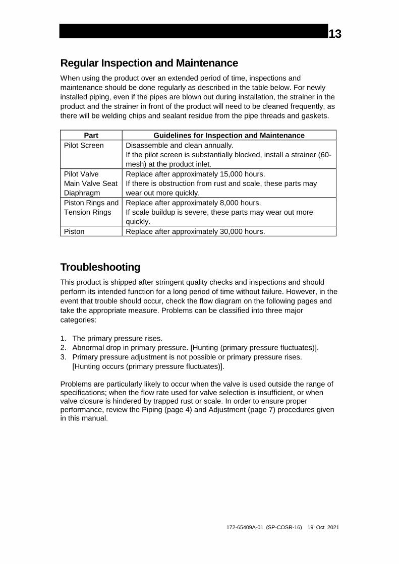
Regular Inspection and Maintenance
When using the product over an extended period of time, inspections and
maintenance should be done regularly as described in the table below. For newly
installed piping, even if the pipes are blown out during installation, the strainer in the
product and the strainer in front of the product will need to be cleaned frequently, as
there will be welding chips and sealant residue from the pipe threads and gaskets.
Part Guidelines for Inspection and Maintenance
Pilot Screen Disassemble and clean annually.
If the pilot screen is substantially blocked, install a strainer (60-
mesh) at the product inlet.
Pilot Valve
Main Valve Seat
Diaphragm
Replace after approximately 15,000 hours.
If there is obstruction from rust and scale, these parts may
wear out more quickly.
Piston Rings and
Tension Rings
Replace after approximately 8,000 hours.
If scale buildup is severe, these parts may wear out more
quickly.
Piston Replace after approximately 30,000 hours.
Troubleshooting
This product is shipped after stringent quality checks and inspections and should
perform its intended function for a long period of time without failure. However, in the
event that trouble should occur, check the flow diagram on the following pages and
take the appropriate measure. Problems can be classified into three major
categories:
1. The primary pressure rises.
2. Abnormal drop in primary pressure. [Hunting (primary pressure fluctuates)].
3. Primary pressure adjustment is not possible or primary pressure rises.
[Hunting occurs (primary pressure fluctuates)].
Problems are particularly likely to occur when the valve is used outside the range of specifications; when the flow rate used for valve selection is insufficient, or when valve closure is hindered by trapped rust or scale. In order to ensure proper performance, review the Piping (page 4) and Adjustment (page 7) procedures given in this manual.
172-65409A-01 (SP-COSR-16) 19 Oct 2021
14
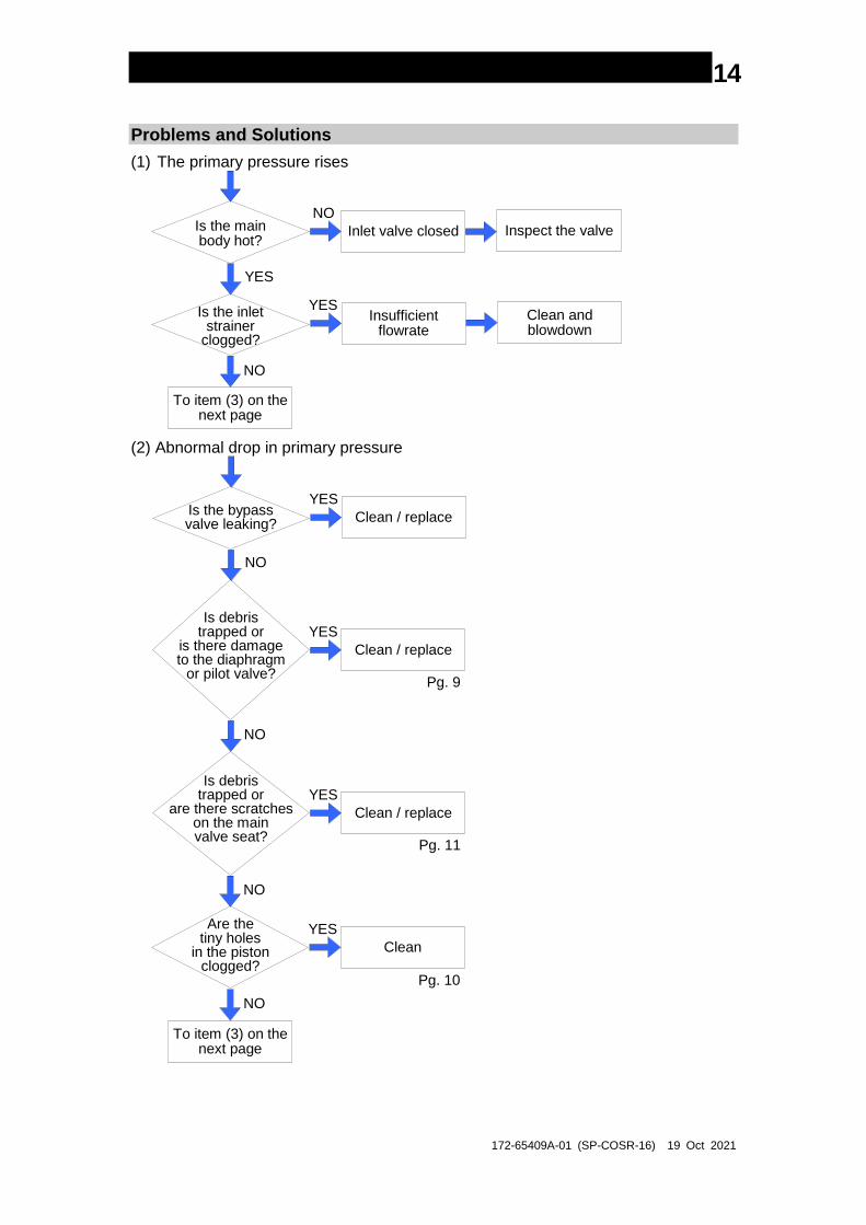
Problems and Solutions
(1) The primary pressure rises
Is the mainbody hot?
Is the inletstrainer
clogged?
To item (3) on thenext page
Inlet valve closed Inspect the valve
NO
YES
NO
Insufficientflowrate
Clean andblowdown
YES
(2) Abnormal drop in primary pressure
Is the bypassvalve leaking?
Is debristrapped or
is there damageto the diaphragm
or pilot valve?
To item (3) on thenext page
Clean / replace
YES
NO
NO
Clean / replace
YES
Is debristrapped or
are there scratcheson the mainvalve seat?
Clean / replace
YES
NO
Are thetiny holes
in the pistonclogged?
Clean
YES
NO
Pg. 9
Pg. 11
Pg. 10
172-65409A-01 (SP-COSR-16) 19 Oct 2021
15
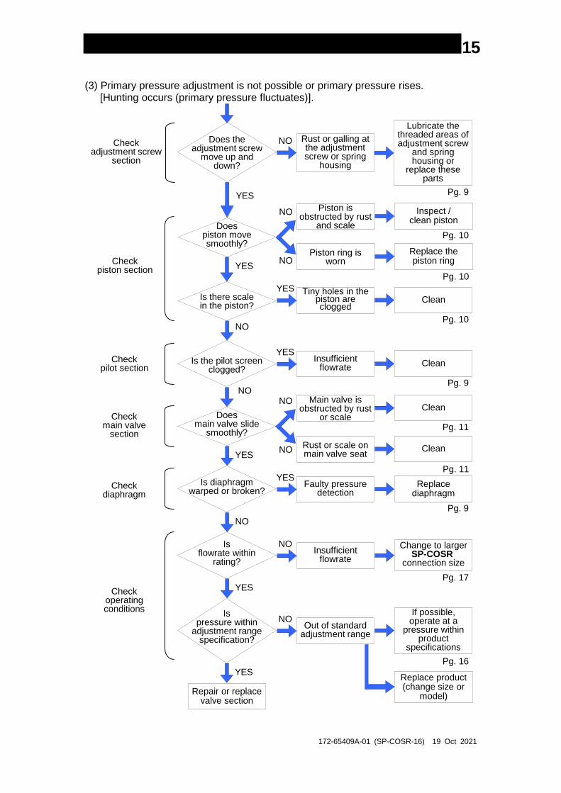
(3) Primary pressure adjustment is not possible or primary pressure rises. [Hunting occurs (primary pressure fluctuates)].
Does theadjustment screw
move up anddown?
Doespiston movesmoothly?
Repair or replacevalve section
Rust or galling at the adjustment screw or spring
housing
Lubricate the threaded areas of adjustment screw
and spring housing or
replace these parts
NO
YES
YES
Piston is obstructed by rust
and scale
Inspect /clean piston
NO
Pg. 9
Piston ring is worn
Replace thepiston ringNO
Pg. 10
Pg. 10
Is there scalein the piston?
Tiny holes in the piston are clogged
Clean
YES
Pg. 10NO
Is the pilot screenclogged?
Insufficient flowrate Clean
YES
Pg. 9
Doesmain valve slide
smoothly?
YES
Main valve is obstructed by rust
or scaleClean
NO
Rust or scale on main valve seat
CleanNO
Pg. 11
NO
Pg. 11
Is diaphragmwarped or broken?
Faulty pressure detection
Replacediaphragm
YES
Pg. 9
NO
Isflowrate within
rating?
Insufficient flowrate
Change to largerSP-COSR
connection size
NO
Pg. 17YES
Ispressure within
adjustment rangespecification?
Out of standard adjustment range
If possible,operate at a
pressure withinproduct
specifications
NO
Pg. 16
YESReplace product(change size or
model)
Check adjustment screw
section
Checkpiston section
Checkpilot section
Checkmain valve
section
Checkdiaphragm
Checkoperating conditions
172-65409A-01 (SP-COSR-16) 19 Oct 2021
16
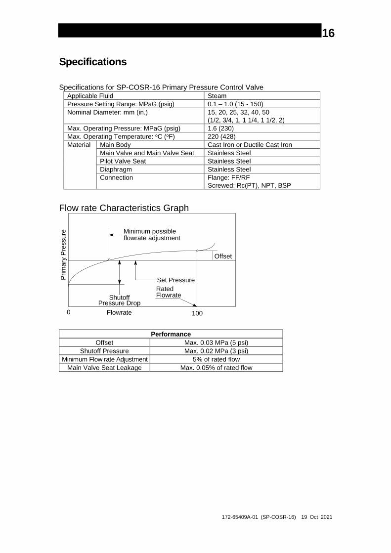
Specifications
Specifications for SP-COSR-16 Primary Pressure Control Valve Applicable Fluid Steam
Pressure Setting Range: MPaG (psig) 0.1 – 1.0 (15 - 150)
Nominal Diameter: mm (in.) 15, 20, 25, 32, 40, 50
(1/2, 3/4, 1, 1 1/4, 1 1/2, 2)
Max. Operating Pressure: MPaG (psig) 1.6 (230)
Max. Operating Temperature: oC (oF) 220 (428)
Material Main Body Cast Iron or Ductile Cast Iron
Main Valve and Main Valve Seat Stainless Steel
Pilot Valve Seat Stainless Steel
Diaphragm Stainless Steel
Connection Flange: FF/RF
Screwed: Rc(PT), NPT, BSP
Flow rate Characteristics Graph
Minimum possibleflowrate adjustment
Set Pressure
RatedFlowrate
Offset
ShutoffPressure Drop
0 100Flowrate
Prim
ary
Pre
ssure
Performance
Offset Max. 0.03 MPa (5 psi)
Shutoff Pressure Max. 0.02 MPa (3 psi)
Minimum Flow rate Adjustment 5% of rated flow
Main Valve Seat Leakage Max. 0.05% of rated flow
172-65409A-01 (SP-COSR-16) 19 Oct 2021
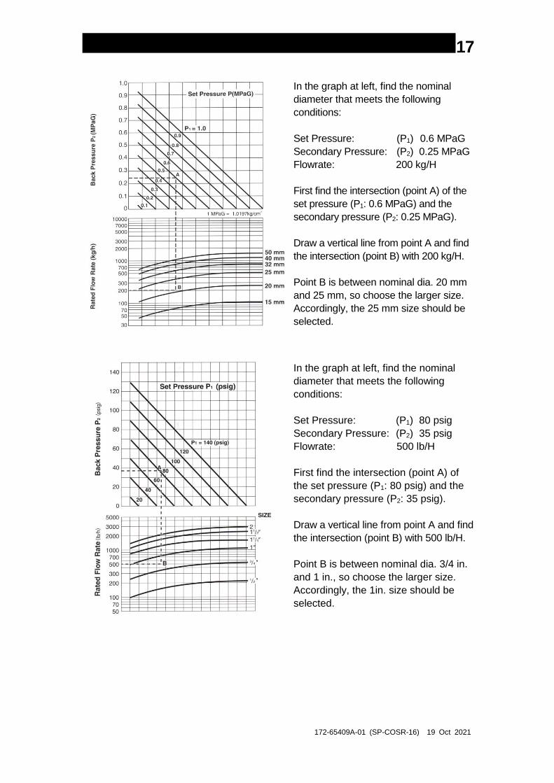
17
In the graph at left, find the nominal
diameter that meets the following
conditions:
Set Pressure: (P1) 0.6 MPaG
Secondary Pressure: (P2) 0.25 MPaG
Flowrate: 200 kg/H
First find the intersection (point A) of the
set pressure (P1: 0.6 MPaG) and the
secondary pressure (P2: 0.25 MPaG).
Draw a vertical line from point A and find
the intersection (point B) with 200 kg/H.
Point B is between nominal dia. 20 mm
and 25 mm, so choose the larger size.
Accordingly, the 25 mm size should be
selected.
In the graph at left, find the nominal
diameter that meets the following
conditions:
Set Pressure: (P1) 80 psig
Secondary Pressure: (P2) 35 psig
Flowrate: 500 lb/H
First find the intersection (point A) of
the set pressure (P1: 80 psig) and the
secondary pressure (P2: 35 psig).
Draw a vertical line from point A and find
the intersection (point B) with 500 lb/H.
Point B is between nominal dia. 3/4 in.
and 1 in., so choose the larger size.
Accordingly, the 1in. size should be
selected.
172-65409A-01 (SP-COSR-16) 19 Oct 2021
18
TLV EXPRESS LIMITED WARRANTY Subject to the limitations set forth below, TLV Corporation, a North Carolina corporation
(“TLV”) warrants that products which are sold by it, TLV CO., LTD., a Japanese
corporation (“TLVJ”) or TLV International, Inc., a Japanese corporation (“TII”), (hereinafter
the “Products”) are designed and manufactured by TLVJ, conform to the specifications
published by TLV for the corresponding part numbers (the “Specifications”) and are free
from defective workmanship and materials. With regard to products or components
manufactured by unrelated third parties (the “Components”), TLV provides no warranty
other than the warranty from the third party manufacturer(s), if any.
Exceptions to Warranty
This warranty does not cover defects or failures caused by:
1. improper shipping, installation, use, handling, etc., by other than TLV or service
representatives authorized by TLV; or
2. dirt, scale or rust, etc.; or
3. improper disassembly and reassembly, or inadequate inspection and
maintenance by other than TLV or service representatives authorized by TLV; or
4. disasters or forces of nature or Acts of God; or
5. abuse, abnormal use, accidents or any other cause beyond the control of TLV; or
6. improper storage, maintenance or repair; or
7. operation of the Products not in accordance with instructions issued with the
Products or with accepted industry practices; or
8. use for a purpose or in a manner for which the Products were not intended; or
9. use of the Products in a manner inconsistent with the Specifications; or
10. use of the Products with Hazardous Fluids (fluids other than steam, air, water,
nitrogen, carbon dioxide and inert gases (helium, neon, argon, krypton, xenon
and radon)); or
11. failure to follow the instructions contained in the TLV Instruction Manual for the
Product.
Duration of Warranty
This warranty is effective for a period of the earlier of: (i) three (3) years after delivery
of Products to the first end user in the case of sealed SST-Series Products for use in
steam pressure service up to 650 psig; (ii) two (2) years after delivery of Products to
the first end user in the case of PowerTrap® units; or (iii) one (1) year after delivery of
Products to the first end user in the case of all other Products. Notwithstanding the
foregoing, asserting a claim under this warranty must be brought by the earlier of one
of the foregoing periods, as applicable, or within five (5) years after the date of delivery
to the initial buyer if not sold initially to the first end user.
ANY IMPLIED WARRANTIES NOT NEGATED HEREBY WHICH MAY ARISE BY OPERATION
OF LAW, INCLUDING THE IMPLIED WARRANTIES OF MERCHANTABILITY AND FITNESS
FOR A PARTICULAR PURPOSE AND ANY EXPRESS WARRANTIES NOT NEGATED
HEREBY, ARE GIVEN SOLELY TO THE INITIAL BUYER AND ARE LIMITED IN DURATION
TO ONE (1) YEAR FROM THE DATE OF SHIPMENT BY TLV.
Exclusive Remedy
THE EXCLUSIVE REMEDY UNDER THIS WARRANTY, UNDER ANY EXPRESS WARRANTY
OR UNDER ANY IMPLIED WARRANTIES NOT NEGATED HEREBY (INCLUDING THE
IMPLIED WARRANTIES OF MERCHANTABILITY AND FITNESS FOR A PARTICULAR
PURPOSE), IS REPLACEMENT; PROVIDED: (a) THE CLAIMED DEFECT IS REPORTED TO
TLV IN WRITING WITHIN THE APPLICABLE WARRANTY PERIOD, INCLUDING A
DETAILED WRITTEN DESCRIPTION OF THE CLAIMED DEFECT AND HOW AND WHEN
172-65409A-01 (SP-COSR-16) 19 Oct 2021
19
THE CLAIMED DEFECTIVE PRODUCT WAS USED; AND (b) THE CLAIMED DEFECTIVE
PRODUCT AND A COPY OF THE PURCHASE INVOICE IS RETURNED TO TLV, FREIGHT
AND TRANSPORTATION COSTS PREPAID, UNDER A RETURN MATERIAL
AUTHORIZATION AND TRACKING NUMBER ISSUED BY TLV. ALL LABOR COSTS,
SHIPPING COSTS, AND TRANSPORTATION COSTS ASSOCIATED WITH THE RETURN
OR REPLACEMENT OF THE CLAIMED DEFECTIVE PRODUCT ARE SOLELY THE
RESPONSIBILITY OF BUYER OR THE FIRST END USER. TLV RESERVES THE RIGHT TO
INSPECT ON THE FIRST END USER’S SITE ANY PRODUCTS CLAIMED TO BE DEFECTIVE
BEFORE ISSUING A RETURN MATERIAL AUTHORIZATION. SHOULD SUCH INSPECTION
REVEAL, IN TLV’S REASONABLE DISCRETION, THAT THE CLAIMED DEFECT IS NOT
COVERED BY THIS WARRANTY, THE PARTY ASSERTING THIS WARRANTY SHALL PAY
TLV FOR THE TIME AND EXPENSES RELATED TO SUCH ON-SITE INSPECTION.
Exclusion of Consequential and Incidental Damages
IT IS SPECIFICALLY ACKNOWLEDGED THAT THIS WARRANTY, ANY OTHER EXPRESS
WARRANTY NOT NEGATED HEREBY, AND ANY IMPLIED WARRANTY NOT NEGATED
HEREBY, INCLUDING THE IMPLIED WARRANTIES OF MERCHANTABILITY AND FITNESS
FOR A PARTICULAR PURPOSE, DO NOT COVER, AND NEITHER TLV, TII NOR TLVJ WILL
IN ANY EVENT BE LIABLE FOR, INCIDENTAL OR CONSEQUENTIAL DAMAGES,
INCLUDING, BUT NOT LIMITED TO LOST PROFITS, THE COST OF DISASSEMBLY AND
SHIPMENT OF THE DEFECTIVE PRODUCT, INJURY TO OTHER PROPERTY, DAMAGE TO
BUYER’S OR THE FIRST END USER’S PRODUCT, DAMAGE TO BUYER’S OR THE FIRST
END USER’S PROCESSES, LOSS OF USE, OR OTHER COMMERCIAL LOSSES. WHERE,
DUE TO OPERATION OF LAW, CONSEQUENTIAL AND INCIDENTAL DAMAGES UNDER
THIS WARRANTY, UNDER ANY OTHER EXPRESS WARRANTY NOT NEGATED HEREBY
OR UNDER ANY IMPLIED WARRANTY NOT NEGATED HEREBY (INCLUDING THE IMPLIED
WARRANTIES OF MERCHANTABILITY AND FITNESS FOR A PARTICULAR PURPOSE)
CANNOT BE EXCLUDED, SUCH DAMAGES ARE EXPRESSLY LIMITED IN AMOUNT TO
THE PURCHASE PRICE OF THE DEFECTIVE PRODUCT. THIS EXCLUSION OF
CONSEQUENTIAL AND INCIDENTAL DAMAGES, AND THE PROVISION OF THIS
WARRANTY LIMITING REMEDIES HEREUNDER TO REPLACEMENT, ARE INDEPENDENT
PROVISIONS, AND ANY DETERMINATION THAT THE LIMITATION OF REMEDIES FAILS OF
ITS ESSENTIAL PURPOSE OR ANY OTHER DETERMINATION THAT EITHER OF THE
ABOVE REMEDIES IS UNENFORCEABLE, SHALL NOT BE CONSTRUED TO MAKE THE
OTHER PROVISIONS UNENFORCEABLE.
Exclusion of Other Warranties
THIS WARRANTY IS IN LIEU OF ALL OTHER WARRANTIES, EXPRESS OR IMPLIED,
AND ALL OTHER WARRANTIES, INCLUDING BUT NOT LIMITED TO THE IMPLIED
WARRANTIES OF MERCHANTABILITY AND FITNESS FOR A PARTICULAR PURPOSE,
ARE EXPRESSLY DISCLAIMED.
Severability
Any provision of this warranty which is invalid, prohibited or unenforceable in any
jurisdiction shall, as to such jurisdiction, be ineffective to the extent of such invalidity,
prohibition or unenforceability without invalidating the remaining provisions hereof,
and any such invalidity, prohibition or unenforceability in any such jurisdiction shall
not invalidate or render unenforceable such provision in any other jurisdiction.
13901 South Lakes Drive, Charlotte, NC 28273-6790, U.S.A.
Tel: [1]-704-597-9070 Fax: [1]-704-583-1610