Embed Size (px)
Citation preview
Surgical User Guide
A BL - TL
2
Thank you for your trust and for choosing the Axiom® Multi Level® implant solution.
This document contains necessary information for using the Axiom® Multi
Level® device with restoration protocols specific to the Axiom® Bone Level and
Axiom® Tissue Level systems, as well as the entire component list.
Success for you means success for us. Our marketing network and team of
experts is always available to you for any further information that you may
need.
Anthogyr
> Scope The Axiom® Multi Level® system is exclusively intended to replace missing teeth. It enables one or more artificial roots to be positioned, onto which dental prostheses are fixed and/ or stabilised. The system allows single-unit, multiple-unit or complete restoration to be performed.
3
A Mult i Level ® SURGICAL USER GUIDE
INSTRUCTIONS AVAILABLE ONLINE
ifu.anthogyr.com You can now find instructions for use (instructions and manuals) for Anthogyr implants and prosthetics parts in PDF
format on our site ifu.anthogyr.com using a PDF reader (Adobe Player).
HOW DOES THE SITE WORK ?
This portal provides the latest instructions for using Anthogyr products.
To find the instructions for your device, please follow these steps:
1- Enter your product reference number, description or GTIN code (Global Trade Item Number) in the search field.
2- Press submit
Your product’s instructions will be available in PDF format, which you can consult online and/or print.
3– Select a language
Our instructions are available in several languages. To select the language you need, click the language choice menu.
This site is optimized for a 1024 x 768 px resolution screen to display instructions on PC or Mac with the following brows-er versions: Microsoft Internet Explorer 11 or higher, Safari 7.0 or higher (Mac only), Chrome 43 or higher, Firefox 38.0
and higher, and IOS and Android.
INFORMATION UPDATES:
Instructions for use are updated regularly and indicated by the “New” pictogram. Updated instructions can impact pa-tient safety. For this reason, we suggest you to avoid local back-ups and advise you to always check the Anthogyr portal. To access archived instructions, click on “View old document versions.” You can also receive paper copies of instructions at no additional cost. To receive paper copies, fill out the form available under the “Contact” tab or include a request with your next order. Make sure to include your desired language. The document will be delivered to you within 7 calendar days. We are available if you have any comments or suggestions, via the “Contact” tab.
4
> Warnings and recommendations The instructions contained in this document describe the different phases of the surgical procedure and prosthetic res-toration to be followed for the Axiom® Multi Level® implant system. A few general features specific to inserting implanta-ble devices are recalled for information. This is not in any way an exhaustive document about implant and prosthetic
practices to which the reader has any right of complaint
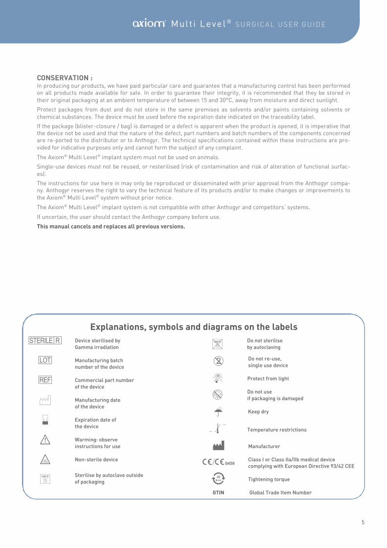
TRAINING : Axiom® Multi Level® components should only be used by practitioners who have been trained in implant practice and/or prosthetic techniques, and who are equipped for this type of procedure. Correct knowledge of surgical techniques and
prosthetics is required to use this system. Specific training is offered and delivered at the Anthogyr company.
The surgical and prosthetic technique for the Axiom® Multi Level® system is performed exclusively in conjunction with the original components and instruments in accordance with the manufacturer’s recommendations. Anthogyr can take no responsibility in case of placement non-compliant with this manual and in case of use of implants or prosthetic parts
or instruments foreign to the system.
Clinical evaluation of the patient and the choice of treatment solution are the sole responsibility of the practitioner. The implant diameter and length must be determined beforehand by the dental practitioner, depending on the clinical situa-tion. Patients should also be informed of potential risks associated with implanting this type of device : oedema, bruising, haemorrhage, periodontal complications, transient or permanent nerve damage, local or systemic infections or inflam-mation, bone fractures, loosening or fracture of the implant, dehiscence, aesthetic problems, aspirating or swallowing
the device, iatrogenic trauma etc.
EQUIPMENT : The practitioner using the system is responsible for the follow-up and maintenance procedures required to identify and treat any complications as early as possible and for ensuring the correct functioning and safety of the device. The refer-ences and the batch numbers of all components implanted, temporarily and/or definitively, must be recorded in the
medical file of the patient.
Follow-up and maintenance are part of the knowledge of a practitioner trained in placing dental implants.
The practitioner is also responsible for defining the different settings for his/her equipment (instrument rotation speed, irrigation flow rate, etc), according to each clinical case, and for confirming that these are in good condition before each
procedure.
Reusable instruments must be cleaned, decontaminated and sterilised before each surgery (even when first used) in accordance with current protocols in hospitals and clinics. The organisation of the operating room, preparation of oper-ating staff and of the patient (premedication, anaesthesia, etc…) should follow current procedures and are the responsi-
bility of the practitioner.
Anthogyr can under no circumstances be held responsible for any harm arising from defective handling or use. In order to avoid swallowing or inhaling small components, it is recommended that these are rendered secure by fixing them to the outside of the mouth with a suture thread. Whenever an instrument is changed, confirm that the contra-angle or key are correctly fixed by applying slight traction and ensure that each part is correctly fixed onto the transfer system out-
side the oral cavity.
5
A Mult i Level ® SURGICAL USER GUIDE
CONSERVATION : In producing our products, we have paid particular care and guarantee that a manufacturing control has been performed on all products made available for sale. In order to guarantee their integrity, it is recommended that they be stored in
their original packaging at an ambient temperature of between 15 and 30°C, away from moisture and direct sunlight.
Protect packages from dust and do not store in the same premises as solvents and/or paints containing solvents or
chemical substances. The device must be used before the expiration date indicated on the traceability label.
If the package (blister-closure / bag) is damaged or a defect is apparent when the product is opened, it is imperative that the device not be used and that the nature of the defect, part numbers and batch numbers of the components concerned are re-ported to the distributor or to Anthogyr. The technical specifications contained within these instructions are pro-
vided for indicative purposes only and cannot form the subject of any complaint.
The Axiom® Multi Level® implant system must not be used on animals.
Single-use devices must not be reused, or resterilised (risk of contamination and risk of alteration of functional surfac-
es).
The instructions for use here in may only be reproduced or disseminated with prior approval from the Anthogyr compa-ny. Anthogyr reserves the right to vary the technical feature of its products and/or to make changes or improvements to
the Axiom® Multi Level® system without prior notice.
The Axiom® Multi Level® implant system is not compatible with other Anthogyr and competitors’ systems.
If uncertain, the user should contact the Anthogyr company before use.
This manual cancels and replaces all previous versions.
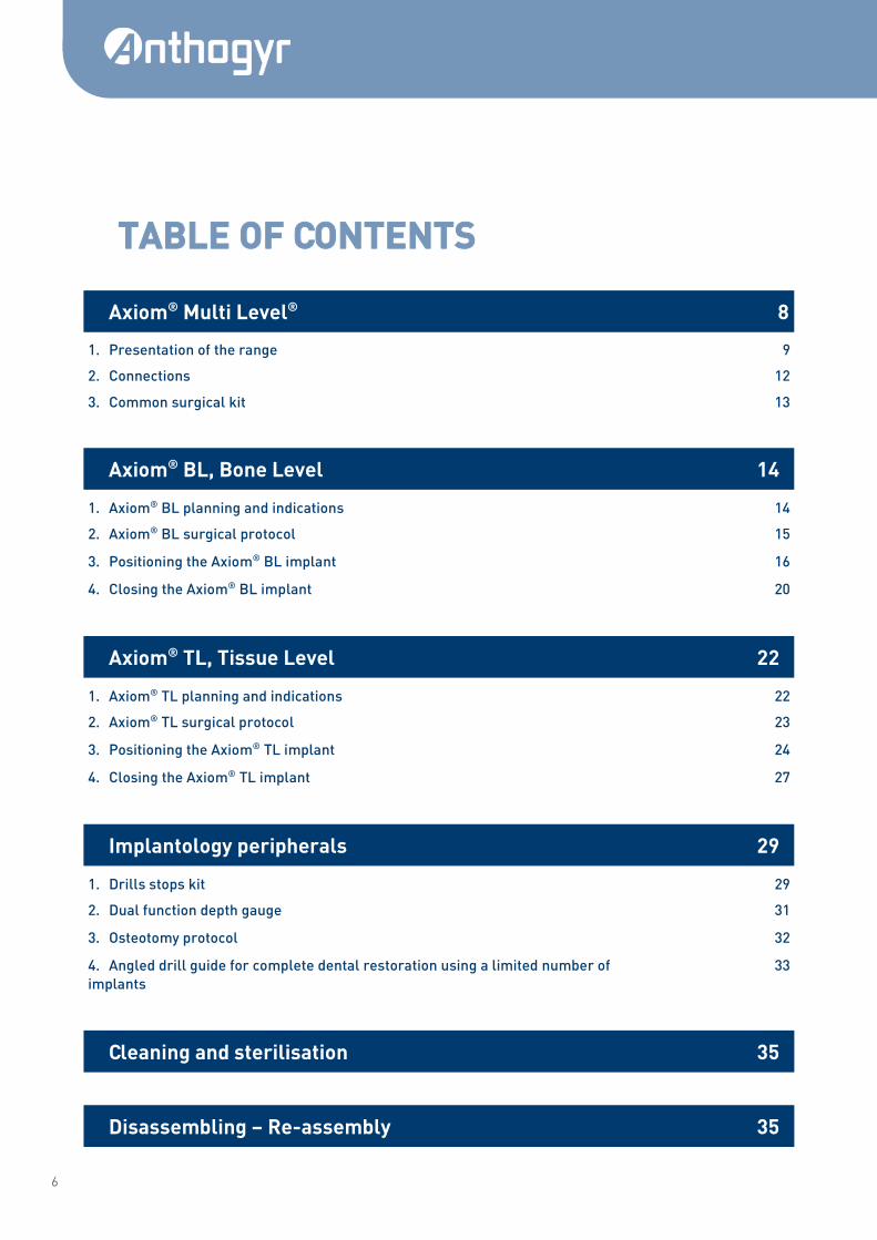
Explanations, symbols and diagrams on the labels
Device sterilised by
Gamma irradiation
Manufacturing batch
number of the device
Commercial part number
of the device
Manufacturing date
of the device
Expiration date of
the device
Warming: observe
instructions for use
Non-sterile device
Sterilise by autoclave outside
of packaging
Do not sterilise
by autoclaving
Do not re-use,
single use device
Protect from light
Do not use
if packaging is damaged
Keep dry
Temperature restrictions
Manufacturer
Class I or Class IIa/IIb medical device
complying with European Directive 93/42 CEE
Tightening torque
GTIN Global Trade Item Number
S
B
O
N
g
F
V
E A
ù
X
W
n G/K
Z
Y
15°C
30°C
k
6
TABLE OF CONTENTS
Axiom® Multi Level® 8
1. Presentation of the range 9
2. Connections 12
3. Common surgical kit 13
Axiom® BL, Bone Level 14
1. Axiom® BL planning and indications 14
2. Axiom® BL surgical protocol 15
3. Positioning the Axiom® BL implant 16
4. Closing the Axiom® BL implant 20
Axiom® TL, Tissue Level 22
1. Axiom® TL planning and indications 22
2. Axiom® TL surgical protocol 23
3. Positioning the Axiom® TL implant 24
4. Closing the Axiom® TL implant 27
Implantology peripherals 29
1. Drills stops kit 29
2. Dual function depth gauge 31
3. Osteotomy protocol 32
4. Angled drill guide for complete dental restoration using a limited number of
implants
33
Cleaning and sterilisation 35
Disassembling – Re-assembly 35
7
A Mult i Level ® SURGICAL USER GUIDE
Component part numbers 36
1. Axiom® BL 36
2. Axiom® TL 39
3. Surgical instruments 46
8
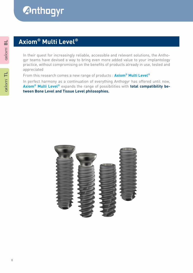
In their quest for increasingly reliable, accessible and relevant solutions, the Antho-gyr teams have devised a way to bring even more added value to your implantology practice, without compromising on the benefits of products already in use, tested and
appreciated
From this research comes a new range of products : Axiom® Multi Level®
In perfect harmony as a continuation of everything Anthogyr has offered until now,
Axiom® Multi Level® expands the range of possibilities with total compatibility be-
tween Bone Level and Tissue Level philosophies.
A T
L
A B
L
Axiom® Multi Level®
9
A Mult i Level ® SURGICAL USER GUIDE
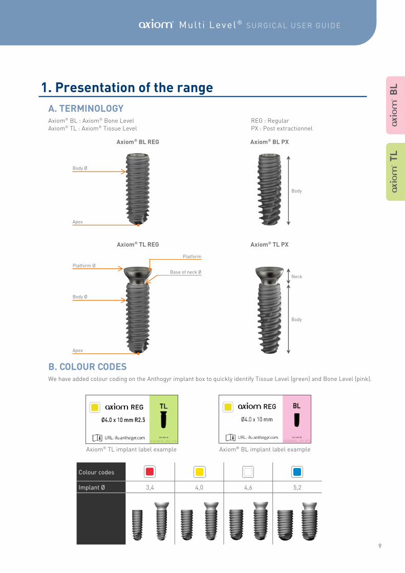
1. Presentation of the range
Axiom® BL : Axiom® Bone Level REG : Regular
Axiom® TL : Axiom® Tissue Level PX : Post extractionnel
We have added colour coding on the Anthogyr implant box to quickly identify Tissue Level (green) and Bone Level (pink).
Axiom® BL REG Axiom® BL PX
Axiom® TL REG Axiom® TL PX
Neck
Body
Platform
Platform Ø
Body Ø
Base of neck Ø
Body
Body Ø
Apex
Apex
Colour codes
3,4 4,0 4,6 5,2 Implant Ø
Axiom® TL implant label example Axiom® BL implant label example
A B
L
A T
L
A. TERMINOLOGY
B. COLOUR CODES
10
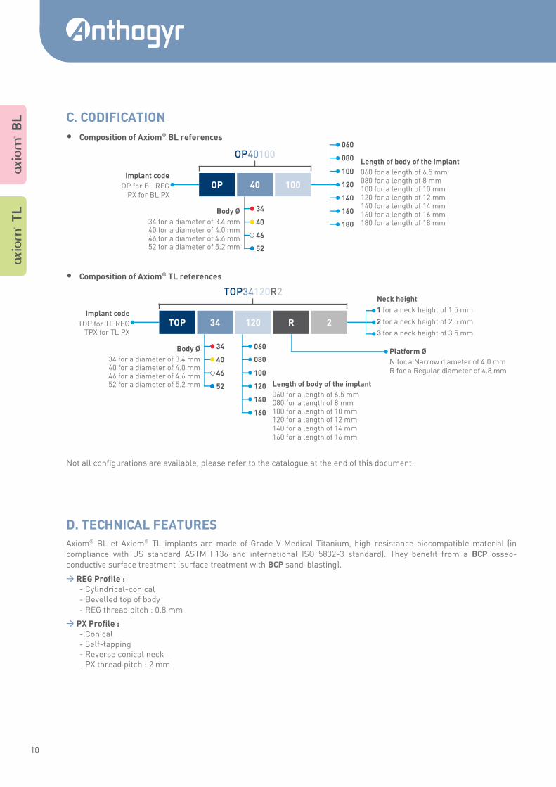
• Composition of Axiom® BL references
• Composition of Axiom® TL references
Not all configurations are available, please refer to the catalogue at the end of this document.
Axiom® BL et Axiom® TL implants are made of Grade V Medical Titanium, high-resistance biocompatible material (in
compliance with US standard ASTM F136 and international ISO 5832-3 standard). They benefit from a BCP osseo-
conductive surface treatment (surface treatment with BCP sand-blasting).
REG Profile : - Cylindrical-conical - Bevelled top of body
- REG thread pitch : 0.8 mm
PX Profile : - Conical - Self-tapping - Reverse conical neck - PX thread pitch : 2 mm
OP 40 100
OP40100
Implant code
OP for BL REG PX for BL PX
Body Ø
34 for a diameter of 3.4 mm 40 for a diameter of 4.0 mm 46 for a diameter of 4.6 mm 52 for a diameter of 5.2 mm
34
40
46
52
Length of body of the implant
060 for a length of 6.5 mm 080 for a length of 8 mm 100 for a length of 10 mm 120 for a length of 12 mm 140 for a length of 14 mm 160 for a length of 16 mm 180 for a length of 18 mm
080
100
120
140
160
060
180
TOP 34 120 R 2
TOP34120R2
Length of body of the implant
060 for a length of 6.5 mm 080 for a length of 8 mm 100 for a length of 10 mm 120 for a length of 12 mm 140 for a length of 14 mm 160 for a length of 16 mm
Implant code
TOP for TL REG TPX for TL PX
Platform Ø
N for a Narrow diameter of 4.0 mm R for a Regular diameter of 4.8 mm
Body Ø
34 for a diameter of 3.4 mm 40 for a diameter of 4.0 mm 46 for a diameter of 4.6 mm 52 for a diameter of 5.2 mm
34
40
46
52
1 for a neck height of 1.5 mm
2 for a neck height of 2.5 mm
3 for a neck height of 3.5 mm
Neck height
080
100
120
140
160
060
C. CODIFICATION
A T
L
A B
L
D. TECHNICAL FEATURES
11
A Mult i Level ® SURGICAL USER GUIDE
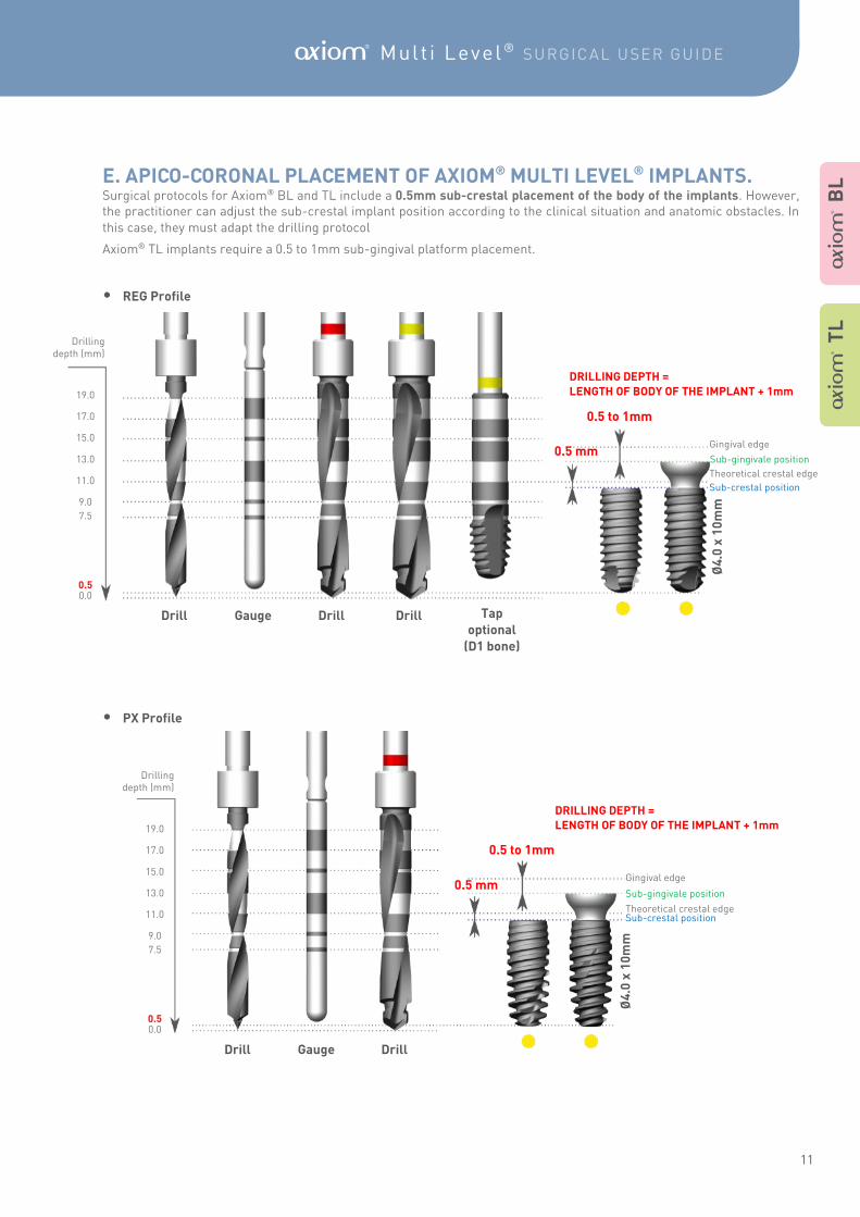
Surgical protocols for Axiom® BL and TL include a 0.5mm sub-crestal placement of the body of the implants. However, the practitioner can adjust the sub-crestal implant position according to the clinical situation and anatomic obstacles. In
this case, they must adapt the drilling protocol
Axiom® TL implants require a 0.5 to 1mm sub-gingival platform placement.
• REG Profile
• PX Profile
A B
L
Drill Gauge Drill
Ø4
.0 x
10
mm
0.5 mm
DRILLING DEPTH =
LENGTH OF BODY OF THE IMPLANT + 1mm
Drilling depth (mm)
19.0
17.0
15.0
13.0
11.0
7.5
9.0
0.5 0.0
Sub-crestal position Theoretical crestal edge
Sub-gingivale position
0.5 to 1mm
Gingival edge
A T
L
Ø4
.0 x
10
mm
0.5 mm
DRILLING DEPTH =
LENGTH OF BODY OF THE IMPLANT + 1mm
7.5
9.0
11.0
13.0
15.0
17.0
19.0
Drill Gauge Drill Drill Tap
optional
(D1 bone)
0.5 0.0
0.5 to 1mm
Theoretical crestal edge
Sub-gingivale position
Gingival edge
Sub-crestal position
Drilling depth (mm)
E. APICO-CORONAL PLACEMENT OF AXIOM® MULTI LEVEL® IMPLANTS.
12
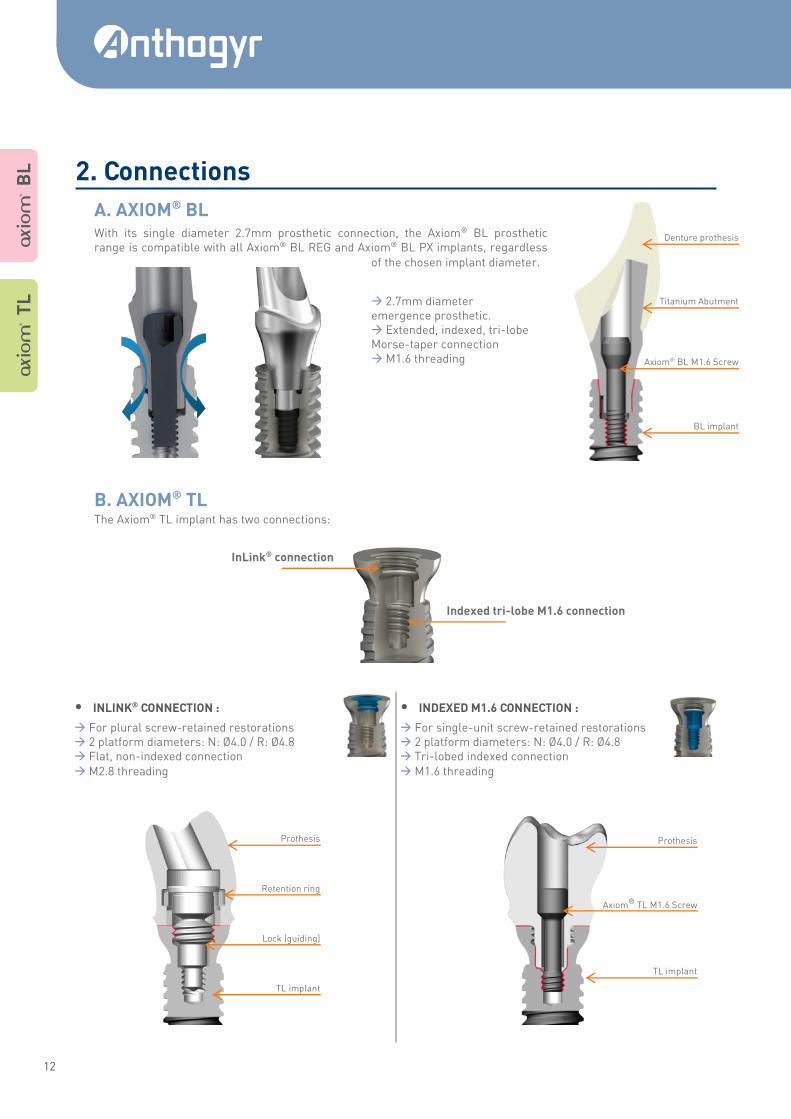
With its single diameter 2.7mm prosthetic connection, the Axiom® BL prosthetic range is compatible with all Axiom® BL REG and Axiom® BL PX implants, regardless
of the chosen implant diameter.
2.7mm diameter emergence prosthetic. Extended, indexed, tri-lobe Morse-taper connection M1.6 threading
The Axiom® TL implant has two connections:
Axiom® BL M1.6 Screw
BL implant
Titanium Abutment
Denture prothesis
InLink® connection
Indexed tri-lobe M1.6 connection
• INLINK® CONNECTION :
For plural screw-retained restorations 2 platform diameters: N: Ø4.0 / R: Ø4.8 Flat, non-indexed connection
M2.8 threading
• INDEXED M1.6 CONNECTION :
For single-unit screw-retained restorations 2 platform diameters: N: Ø4.0 / R: Ø4.8 Tri-lobed indexed connection
M1.6 threading
Axiom® TL M1.6 Screw
TL implant
Prothesis
A T
L
A B
L
Retention ring
TL implant
Prothesis
Lock (guiding)
2. Connections
A. AXIOM® BL
B. AXIOM® TL
13
A Mult i Level ® SURGICAL USER GUIDE
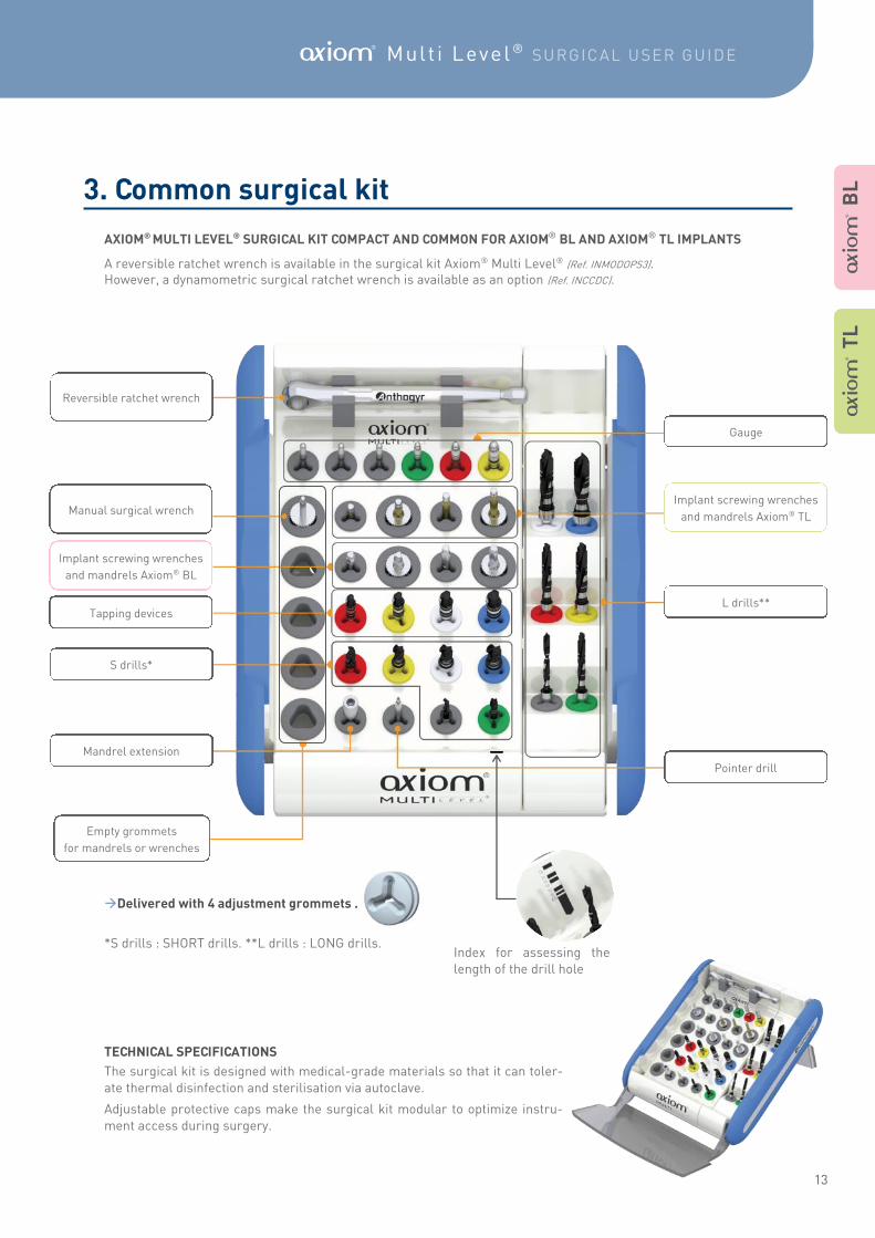
L drills**
Gauge
Implant screwing wrenches
and mandrels Axiom® TL
Reversible ratchet wrench
Pointer drill
Tapping devices
Implant screwing wrenches
and mandrels Axiom® BL
Manual surgical wrench
Mandrel extension
S drills*
AXIOM® MULTI LEVEL® SURGICAL KIT COMPACT AND COMMON FOR AXIOM® BL AND AXIOM® TL IMPLANTS
A reversible ratchet wrench is available in the surgical kit Axiom® Multi Level® (Ref. INMODOPS3). However, a dynamometric surgical ratchet wrench is available as an option (Ref. INCCDC).
Delivered with 4 adjustment grommets .
*S drills : SHORT drills. **L drills : LONG drills.
TECHNICAL SPECIFICATIONS
The surgical kit is designed with medical-grade materials so that it can toler-
ate thermal disinfection and sterilisation via autoclave.
Adjustable protective caps make the surgical kit modular to optimize instru-
ment access during surgery.
A B
L
A T
L
Empty grommets
for mandrels or wrenches
Index for assessing the
length of the drill hole
3. Common surgical kit
14
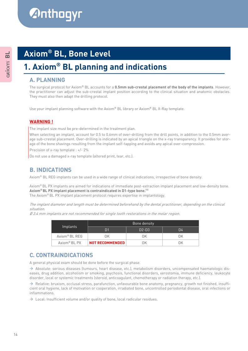
The surgical protocol for Axiom® BL accounts for a 0.5mm sub-crestal placement of the body of the implants. However, the practitioner can adjust the sub-crestal implant position according to the clinical situation and anatomic obstacles.
They must also then adapt the drilling protocol.
Use your implant planning software with the Axiom® BL library or Axiom® BL X-Ray template.
WARNING !
The implant size must be pre-determined in the treatment plan.
When selecting an implant, account for 0.5 to 0.6mm of over-drilling from the drill points, in addition to the 0.5mm aver-age sub-crestal placement. Over-drilling is indicated by an apical triangle on the x-ray transparency. It provides for stor-
age of the bone shavings resulting from the implant self-tapping and avoids any apical over-compression.
Precision of x-ray template : +/- 2%
Do not use a damaged x-ray template (altered print, tear, etc.).
Axiom® BL REG implants can be used in a wide range of clinical indications, irrespective of bone density. Axiom® BL PX implants are aimed for indications of immediate post-extraction implant placement and low-density bone. Axiom® BL PX implant placement is contraindicated in D1-type bone.(1) The Axiom® BL PX implant placement protocol requires expertise in implantology. The implant diameter and length must be determined beforehand by the dental practitioner, depending on the clinical situation. Ø 3.4 mm implants are not recommended for single tooth restorations in the molar region.
A general physical exam should be done before the surgical phase.
Absolute: serious diseases (tumours, heart disease, etc.), metabolism disorders, uncompensated haematologic dis-eases, drug addition, alcoholism or smoking, psychosis, functional disorders, xerostomia, immune deficiency, leukocyte
disorder, local or systemic treatments (steroid, anticoagulant, chemotherapy or radiation therapy, etc.).
Relative: bruxism, occlusal stress, parafunction, unfavourable bone anatomy, pregnancy, growth not finished, insuffi-cient oral hygiene, lack of motivation or cooperation, irradiated bone, uncontrolled periodontal disease, oral infections or
inflammations.
Local: Insufficient volume and/or quality of bone, local radicular residues.
A B
L
A. PLANNING
Axiom® BL, Bone Level
1. Axiom® BL planning and indications
B. INDICATIONS
C. CONTRAINDICATIONS
Implants Bone density
D1 D2-D3 D4
Axiom® BL REG OK OK OK
Axiom® BL PX NOT RECOMMENDED OK OK
15
A Mult i Level ® SURGICAL USER GUIDE
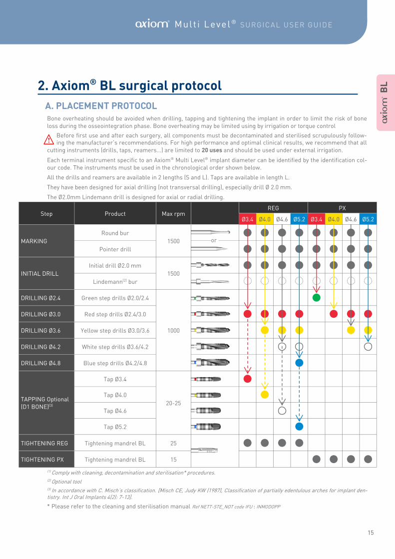
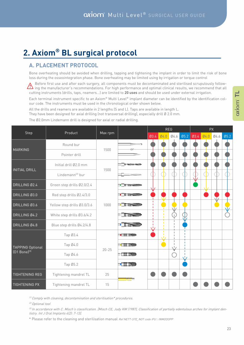
Bone overheating should be avoided when drilling, tapping and tightening the implant in order to limit the risk of bone
loss during the osseointegration phase. Bone overheating may be limited using by irrigation or torque control
Before first use and after each surgery, all components must be decontaminated and sterilised scrupulously follow-ing the manufacturer’s recommendations. For high performance and optimal clinical results, we recommend that all
cutting instruments (drills, taps, reamers...) are limited to 20 uses and should be used under external irrigation.
Each terminal instrument specific to an Axiom® Multi Level® implant diameter can be identified by the identification col-
our code. The instruments must be used in the chronological order shown below.
All the drills and reamers are available in 2 lengths (S and L). Taps are available in length L.
They have been designed for axial drilling (not transversal drilling), especially drill Ø 2.0 mm.
The Ø2.0mm Lindemann drill is designed for axial or radial drilling.
(1) Comply with cleaning, decontamination and sterilisation* procedures. (2) Optional tool (3) In accordance with C. Misch’s classification. [Misch CE, Judy KW (1987), Classification of partially edentulous arches for implant den-tistry. Int J Oral Implants 4(2): 7-13].
* Please refer to the cleaning and sterilisation manual Ref NETT-STE_NOT code IFU : INMODOPP
E
Step Product Max rpm REG PX
Ø3.4 Ø4.0 Ø4.6 Ø5.2 Ø3.4 Ø4.0 Ø4.6 Ø5.2
MARKING
Round bur
1500
Pointer drill
INITIAL DRILL
Initial drill Ø2.0 mm
1500
Lindemann(2) bur
DRILLING Ø2.4 Green step drills Ø2.0/2.4
1000
DRILLING Ø3.0 Red step drills Ø2.4/3.0
DRILLING Ø3.6 Yellow step drills Ø3.0/3.6
DRILLING Ø4.2 White step drills Ø3.6/4.2
DRILLING Ø4.8 Blue step drills Ø4.2/4.8
TAPPING Optional
(D1 BONE)(3)
Tap Ø3.4
20-25
Tap Ø4.0
Tap Ø4.6
Tap Ø5.2
TIGHTENING REG Tightening mandrel BL 25
TIGHTENING PX Tightening mandrel BL 15
or
A B
L
2. Axiom® BL surgical protocol
A. PLACEMENT PROTOCOL
16
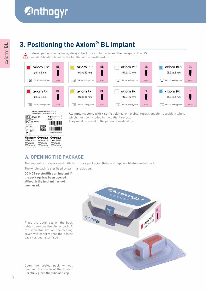
Before opening the package, always check the implant size and the design (REG or PX)
See identification label on the top flap of the cardboard box)
All implants come with 4 self-sticking, removable, repositionable traceability labels which must be included in the patient record. They must be saved in the patient’s medical file.
The implant is pre-packaged with its primary packaging (tube and cap) in a blister-sealed pack.
The whole pack is sterilised by gamma radiation.
DO NOT re-sterillise an implant if
the package has been opened
although the implant has not
been used.
Place the outer box on the back table to remove the blister pack. A red indicator dot on the sealing cover will confirm that the blister pack has been sterilised .
Open the sealed pack without touching the inside of the blister. Carefully place the tube and cap
E
A B
L
3. Positioning the Axiom® BL implant
A. OPENING THE PACKAGE
17
A Mult i Level ® SURGICAL USER GUIDE
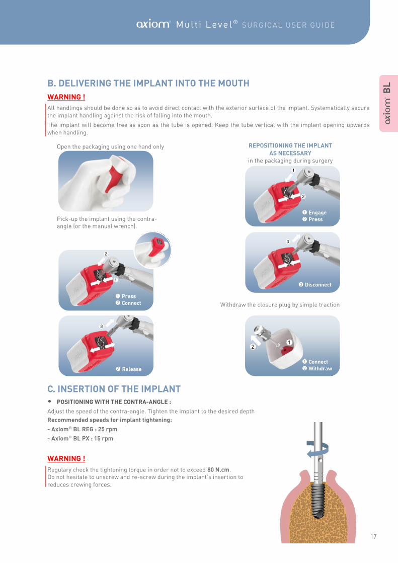
Open the packaging using one hand only Pick-up the implant using the contra- angle (or the manual wrench).
REPOSITIONING THE IMPLANT
AS NECESSARY in the packaging during surgery
Withdraw the closure plug by simple traction
WARNING !
All handlings should be done so as to avoid direct contact with the exterior surface of the implant. Systematically secure
the implant handling against the risk of falling into the mouth.
The implant will become free as soon as the tube is opened. Keep the tube vertical with the implant opening upwards
when handling.
1 Press
2 Connect
3 Release
1 Engage
2 Press
3 Disconnect
1 Connect
2 Withdraw
• POSITIONING WITH THE CONTRA-ANGLE :
Adjust the speed of the contra-angle. Tighten the implant to the desired depth
Recommended speeds for implant tightening:
- Axiom® BL REG : 25 rpm
- Axiom® BL PX : 15 rpm
WARNING !
Regulary check the tightening torque in order not to exceed 80 N.cm. Do not hesitate to unscrew and re-screw during the implant’s insertion to
reduces crewing forces.
A B
L B. DELIVERING THE IMPLANT INTO THE MOUTH
C. INSERTION OF THE IMPLANT
18
• MANUAL POSITIONING :
With the surgical ratchet
Manually pre-tighten the implant into the implant shaft us-ing the torque wrench or the manual screw-down applica-
tion instrument(1) . (Ref. INPIM/INPIL)
Assemble the surgical ratchet wrench and tighten until the
desired depth is reached.
Using the universal surgical instrument
The surgical universal instrument may be used in the superi-or zone of the front maxilla to control and guide the insertion
of Axiom® PX while respecting the implant axis.
WARNING !
No tightening torque control. However, it is possible to evaluate the torque using the surgical dynamometric ratchet
wrench Ref. INCCDC. Be careful not apply excessive forces to the connection. Do not hesitate to unscrew and re-screw dur-
ing the implant’s insertion to reduce screwing forces.
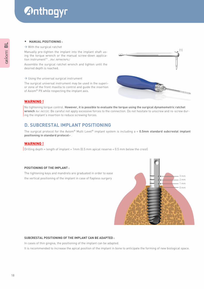
The surgical protocol for the Axiom® Multi Level® implant system is including a « 0.5mm standard subcrestal implant
positioning in standard protocol» .
WARNING !
Drilling depth = length of implant + 1mm (0.5 mm apical reserve + 0.5 mm below the crest)
POSITIONING OF THE IMPLANT :
The tightening keys and mandrels are graduated in order to ease
the vertical positioning of the implant in case of flapless surgery
SUBCRESTAL POSITIONING OF THE IMPLANT CAN BE ADAPTED :
In cases of thin gingiva, the positioning of the implant can be adapted.
It is recommended to increase the apical position of the implant in bone to anticipate the forming of new biological space.
(1)
A B
L
3 mm
2 mm
1 mm
0 mm
D. SUBCRESTAL IMPLANT POSITIONING
19
A Mult i Level ® SURGICAL USER GUIDE
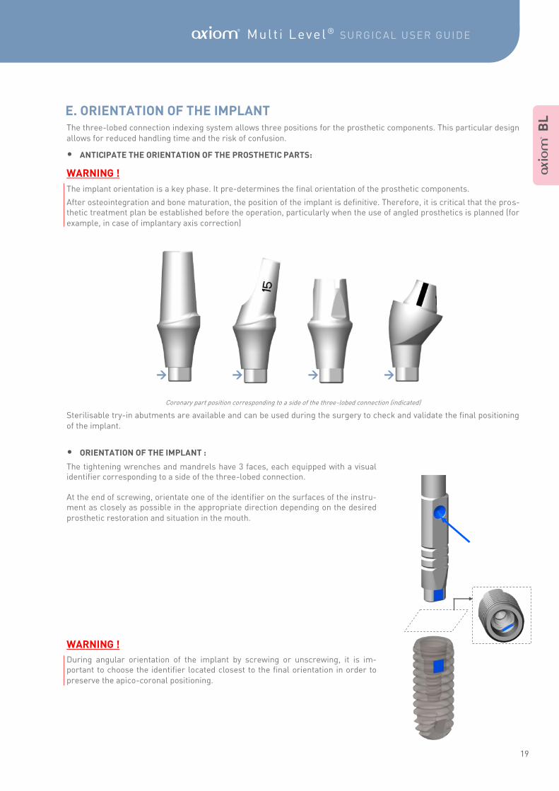
The three-lobed connection indexing system allows three positions for the prosthetic components. This particular design
allows for reduced handling time and the risk of confusion.
• ANTICIPATE THE ORIENTATION OF THE PROSTHETIC PARTS:
WARNING !
The implant orientation is a key phase. It pre-determines the final orientation of the prosthetic components.
After osteointegration and bone maturation, the position of the implant is definitive. Therefore, it is critical that the pros-thetic treatment plan be established before the operation, particularly when the use of angled prosthetics is planned (for
example, in case of implantary axis correction)
Coronary part position corresponding to a side of the three-lobed connection (indicated)
Sterilisable try-in abutments are available and can be used during the surgery to check and validate the final positioning
of the implant.
• ORIENTATION OF THE IMPLANT :
The tightening wrenches and mandrels have 3 faces, each equipped with a visual identifier corresponding to a side of the three-lobed connection. At the end of screwing, orientate one of the identifier on the surfaces of the instru-ment as closely as possible in the appropriate direction depending on the desired
prosthetic restoration and situation in the mouth.
WARNING !
During angular orientation of the implant by screwing or unscrewing, it is im-portant to choose the identifier located closest to the final orientation in order to
preserve the apico-coronal positioning.
A B
L
E. ORIENTATION OF THE IMPLANT
20
A B
L
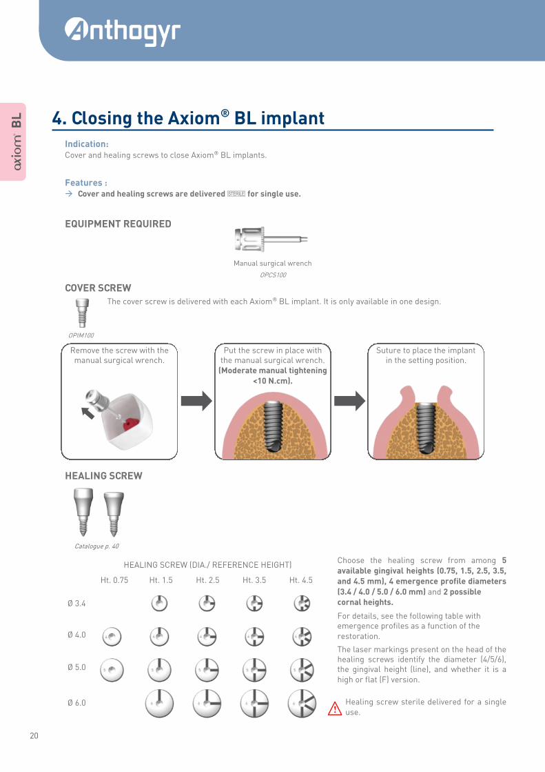
Indication: Cover and healing screws to close Axiom® BL implants.
Features : Cover and healing screws are delivered Q for single use.
EQUIPMENT REQUIRED
COVER SCREW
The cover screw is delivered with each Axiom® BL implant. It is only available in one design.
OPIM100
HEALING SCREW
Catalogue p. 40
Choose the healing screw from among 5
available gingival heights (0.75, 1.5, 2.5, 3.5,
and 4.5 mm), 4 emergence profile diameters
(3.4 / 4.0 / 5.0 / 6.0 mm) and 2 possible
cornal heights.
For details, see the following table with emergence profiles as a function of the
restoration.
The laser markings present on the head of the healing screws identify the diameter (4/5/6), the gingival height (line), and whether it is a
high or flat (F) version.
Healing screw sterile delivered for a single
use.
HEALING SCREW (DIA./ REFERENCE HEIGHT)
Ht. 0.75 Ht. 1.5 Ht. 2.5 Ht. 3.5 Ht. 4.5
Ø 3.4
Ø 4.0
Ø 5.0
Ø 6.0
E
Manual surgical wrench
OPCS100
Put the screw in place with
the manual surgical wrench. (Moderate manual tightening
<10 N.cm).
Remove the screw with the manual surgical wrench.
Suture to place the implant
in the setting position.
4. Closing the Axiom® BL implant
21
A Mult i Level ® SURGICAL USER GUIDE
A B
L
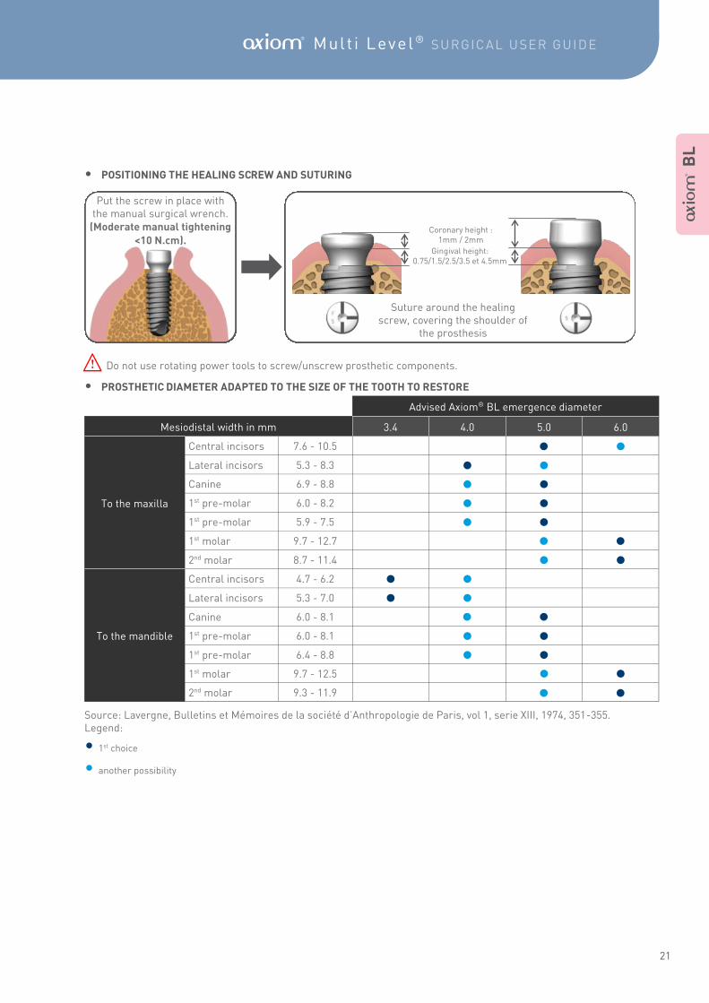
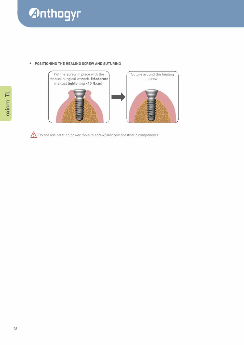
• POSITIONING THE HEALING SCREW AND SUTURING
Do not use rotating power tools to screw/unscrew prosthetic components.
• PROSTHETIC DIAMETER ADAPTED TO THE SIZE OF THE TOOTH TO RESTORE
Source: Lavergne, Bulletins et Mémoires de la société d’Anthropologie de Paris, vol 1, serie XIII, 1974, 351-355. Legend:
• 1st choice
• another possibility
Put the screw in place with
the manual surgical wrench. (Moderate manual tightening
<10 N.cm).
Suture around the healing screw, covering the shoulder of
the prosthesis
Coronary height : 1mm / 2mm
Gingival height: 0.75/1.5/2.5/3.5 et 4.5mm
E
•
Advised Axiom® BL emergence diameter
Mesiodistal width in mm 3.4 4.0 5.0 6.0
To the maxilla
Central incisors 7.6 - 10.5
Lateral incisors 5.3 - 8.3
Canine 6.9 - 8.8
1st pre-molar 6.0 - 8.2
1st pre-molar 5.9 - 7.5
1st molar 9.7 - 12.7
2nd molar 8.7 - 11.4
Central incisors 4.7 - 6.2
To the mandible
Lateral incisors 5.3 - 7.0
Canine 6.0 - 8.1
1st pre-molar 6.0 - 8.1
1st pre-molar 6.4 - 8.8
1st molar 9.7 - 12.5
2nd molar 9.3 - 11.9
• •
• • • • • • •
• • • •
• • • •
• • • • • •
• • • •
22
The surgical protocol for Axiom® TL accounts for a 0.5mm sub-crestal placement of the body of the implants. However,
the practitioner can adjust the sub-crestal implant position according to the clinical situation.
Anthogyr advises a 0.5 to 1 mm sub-gingival plateform implant position.
Use your implant planning software with the Axiom® BL library or Axiom® TL x-ray template.
WARNING !
The implant size must be pre-determined in the treatment plan.
When selecting an implant, account for 0.5 to 0.6mm of over-drilling from the drill points, in addition to the 0.5mm aver-age sub-crestal placement. Over-drilling is indicated by an apical triangle on the x-ray transparency. It provides for stor-
age of the bone shavings resulting from the implant self-tapping and avoids any apical over-compression.
Precision of x-ray template : +/- 2%
Do not use a damaged x-ray template (altered print, tear, etc.).
Axiom® TL REG implants can be used in a wide range of clinical indications, irrespective of bone density. Axiom® TL PX implants are aimed for indications of immediate post-extraction implant placement and low-density bone (D1 type bone excluded). Axiom® TL PX implant placement is contraindicated in D1-type bone.(1) The Axiom® TL PX implant placement protocol requires expertise in implantology. The implant diameter and length must be determined beforehand by the dental practitioner, depending on the clinical situation.
A general physical exam should be done before the surgical phase.
Absolute: serious diseases (tumours, heart disease, etc.), metabolism disorders, uncompensated haematologic dis-eases, drug addition, alcoholism or smoking, psychosis, functional disorders, xerostomia, immune deficiency, leukocyte
disorder, local or systemic treatments (steroid, anticoagulant, chemotherapy or radiation therapy, etc.).
Relative: bruxism, occlusal stress, parafunction, unfavourable bone anatomy, pregnancy, growth not finished, insuffi-cient oral hygiene, lack of motivation or cooperation, irradiated bone, uncontrolled periodontal disease, oral infections or
inflammations.
Local: Insufficient volume and/or quality of bone, local radicular residues.
A T
L
A. PLANNING
Axiom® TL, Tissue Level
1. Axiom® TL planning and indications
B. INDICATIONS
C. CONTRAINDICATIONS
Implants Bone density
D1 D2-D3 D4
Axiom® TL REG OK OK OK
Axiom® TL PX NOT RECOMMENDED OK OK
23
A Mult i Level ® SURGICAL USER GUIDE
Bone overheating should be avoided when drilling, tapping and tightening the implant in order to limit the risk of bone
loss during the osseointegration phase. Bone overheating may be limited using by irrigation or torque control
Before first use and after each surgery, all components must be decontaminated and sterilised scrupulously follow-ing the manufacturer’s recommendations. For high performance and optimal clinical results, we recommend that all
cutting instruments (drills, taps, reamers...) are limited to 20 uses and should be used under external irrigation.
Each terminal instrument specific to an Axiom® Multi Level® implant diameter can be identified by the identification col-
our code. The instruments must be used in the chronological order shown below.
All the drills and reamers are available in 2 lengths (S and L). Taps are available in length L.
They have been designed for axial drilling (not transversal drilling), especially drill Ø 2.0 mm.
The Ø2.0mm Lindemann drill is designed for axial or radial drilling.
(1) Comply with cleaning, decontamination and sterilisation* procedures.
(2) Optional tool (3) In accordance with C. Misch’s classification. [Misch CE, Judy KW (1987), Classification of partially edentulous arches for implant den-tistry. Int J Oral Implants 4(2): 7-13].
* Please refer to the cleaning and sterilisation manual Ref NETT-STE_NOT code IFU : INMODOPP
E
A T
L
or
2. Axiom® BL surgical protocol
A. PLACEMENT PROTOCOL
Step Product Max rpm REG PX
Ø3.4 Ø4.0 Ø4.6 Ø5.2 Ø3.4 Ø4.0 Ø4.6 Ø5.2
MARKING
Round bur
1500
Pointer drill
INITIAL DRILL
Initial drill Ø2.0 mm
1500
Lindemann(2) bur
DRILLING Ø2.4 Green step drills Ø2.0/2.4
1000
DRILLING Ø3.0 Red step drills Ø2.4/3.0
DRILLING Ø3.6 Yellow step drills Ø3.0/3.6
DRILLING Ø4.2 White step drills Ø3.6/4.2
DRILLING Ø4.8 Blue step drills Ø4.2/4.8
TAPPING Optional
(D1 Bone)(3)
Tap Ø3.4
20-25
Tap Ø4.0
Tap Ø4.6
Tap Ø5.2
TIGHTENING REG Tightening mandrel TL 25
TIGHTENING PX Tightening mandrel TL 15
24
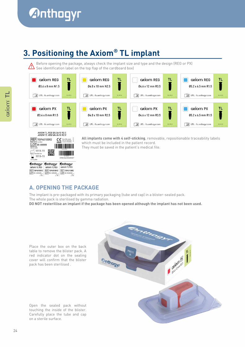
Before opening the package, always check the implant size and type and the design (REG or PX)
See identification label on the top flap of the cardboard box)
All implants come with 4 self-sticking, removable, repositionable traceability labels which must be included in the patient record. They must be saved in the patient’s medical file.
The implant is pre-packaged with its primary packaging (tube and cap) in a blister-sealed pack. The whole pack is sterilised by gamma radiation. DO NOT resterillise an implant if the package has been opened although the implant has not been used.
Place the outer box on the back table to remove the blister pack. A red indicator dot on the sealing cover will confirm that the blister pack has been sterilised .
Open the sealed pack without touching the inside of the blister. Carefully place the tube and cap on a sterile surface.
E
A T
L
3. Positioning the Axiom® TL implant
A. OPENING THE PACKAGE
25
A Mult i Level ® SURGICAL USER GUIDE
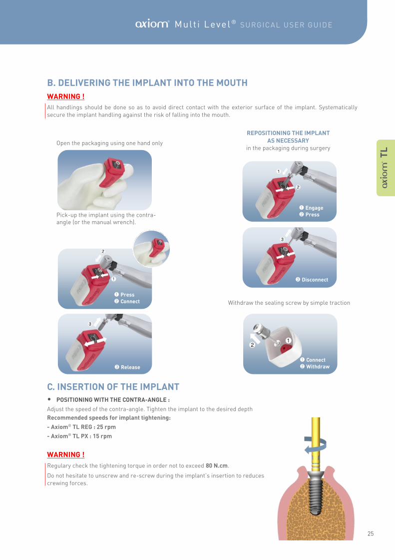
Open the packaging using one hand only Pick-up the implant using the contra- angle (or the manual wrench).
REPOSITIONING THE IMPLANT
AS NECESSARY in the packaging during surgery
Withdraw the sealing screw by simple traction
• POSITIONING WITH THE CONTRA-ANGLE :
Adjust the speed of the contra-angle. Tighten the implant to the desired depth
Recommended speeds for implant tightening:
- Axiom® TL REG : 25 rpm
- Axiom® TL PX : 15 rpm
WARNING !
Regulary check the tightening torque in order not to exceed 80 N.cm.
Do not hesitate to unscrew and re-screw during the implant’s insertion to reduces
crewing forces.
1 Press
2 Connect
3 Release
1 Engage
2 Press
3 Disconnect
A T
L
1 Connect
2 Withdraw
B. DELIVERING THE IMPLANT INTO THE MOUTH
WARNING !
All handlings should be done so as to avoid direct contact with the exterior surface of the implant. Systematically
secure the implant handling against the risk of falling into the mouth.
C. INSERTION OF THE IMPLANT
26
1 mm
2 mm
0 mm
• MANUAL POSITIONING:
With the surgical ratchet
Manually pre-tighten the implant into the implant shaft using the torque wrench
Assemble the surgical ratchet wrench and tighten until the desired depth is reached.
WARNING !
No tightening torque control.
However, it is possible to evaluate the torque using the surgical dynamometric ratchet wrench (Ref. INCCDC). Be careful not apply excessive forces to the connection. Do not hesitate to unscrew and re-screw during the implant’s
insertion to reduce screwing forces.
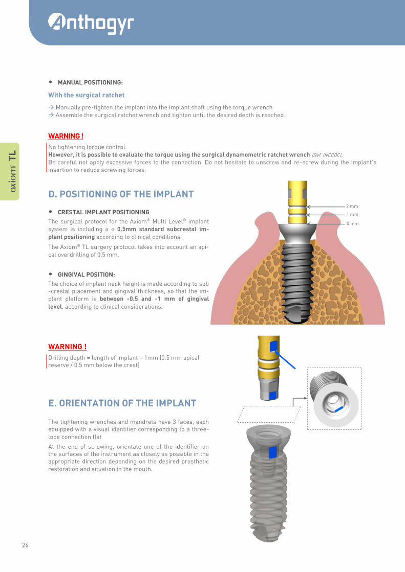
• CRESTAL IMPLANT POSITIONING
The surgical protocol for the Axiom® Multi Level® implant
system is including a « 0.5mm standard subcrestal im-
plant positioning according to clinical conditions.
The Axiom® TL surgery protocol takes into account an api-
cal overdrilling of 0.5 mm.
• GINGIVAL POSITION:
The choice of implant neck height is made according to sub-crestal placement and gingival thickness, so that the im-
plant platform is between -0.5 and -1 mm of gingival
level, according to clinical considerations.
WARNING !
Drilling depth = length of implant + 1mm (0.5 mm apical reserve / 0.5 mm below the crest)
The tightening wrenches and mandrels have 3 faces, each equipped with a visual identifier corresponding to a three-
lobe connection flat
At the end of screwing, orientate one of the identifier on the surfaces of the instrument as closely as possible in the appropriate direction depending on the desired prosthetic
restoration and situation in the mouth.
A T
L
E. ORIENTATION OF THE IMPLANT
D. POSITIONING OF THE IMPLANT
27
A Mult i Level ® SURGICAL USER GUIDE
Suture around the neck of the implant.
Manual surgical wrench
OPCS100
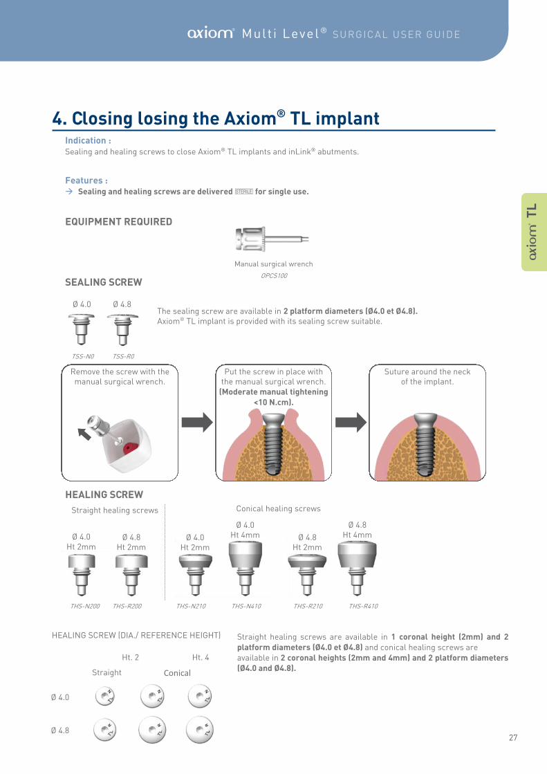
Indication : Sealing and healing screws to close Axiom® TL implants and inLink® abutments.
Features : Sealing and healing screws are delivered Q for single use.
EQUIPMENT REQUIRED
SEALING SCREW
The sealing screw are available in 2 platform diameters (Ø4.0 et Ø4.8). Axiom® TL implant is provided with its sealing screw suitable.
TSS-N0 TSS-R0
HEALING SCREW
THS-N200 THS-R200 THS-N210 THS-N410 THS-R210 THS-R410
Straight healing screws are available in 1 coronal height (2mm) and 2
platform diameters (Ø4.0 et Ø4.8) and conical healing screws are
available in 2 coronal heights (2mm and 4mm) and 2 platform diameters
(Ø4.0 and Ø4.8).
Conical healing screws
Ø 4.0 Ht 2mm
Ø 4.8 Ht 2mm
Ø 4.0 Ø 4.8
HEALING SCREW (DIA./ REFERENCE HEIGHT)
Ht. 2 Ht. 4
Straight Conical
Ø 4.0
Ø 4.8
Straight healing screws
A T
L
Put the screw in place with the manual surgical wrench.
(Moderate manual tightening
<10 N.cm).
Remove the screw with the manual surgical wrench.
Ø 4.0 Ht 2mm
Ø 4.0 Ht 4mm Ø 4.8
Ht 2mm
Ø 4.8 Ht 4mm
4. Closing losing the Axiom® TL implant
28
A T
L
Suture around the healing
screw
• POSITIONING THE HEALING SCREW AND SUTURING
Do not use rotating power tools to screw/unscrew prosthetic components.
Put the screw in place with the
manual surgical wrench. (Moderate
manual tightening <10 N.cm).
E
29
A Mult i Level ® SURGICAL USER GUIDE
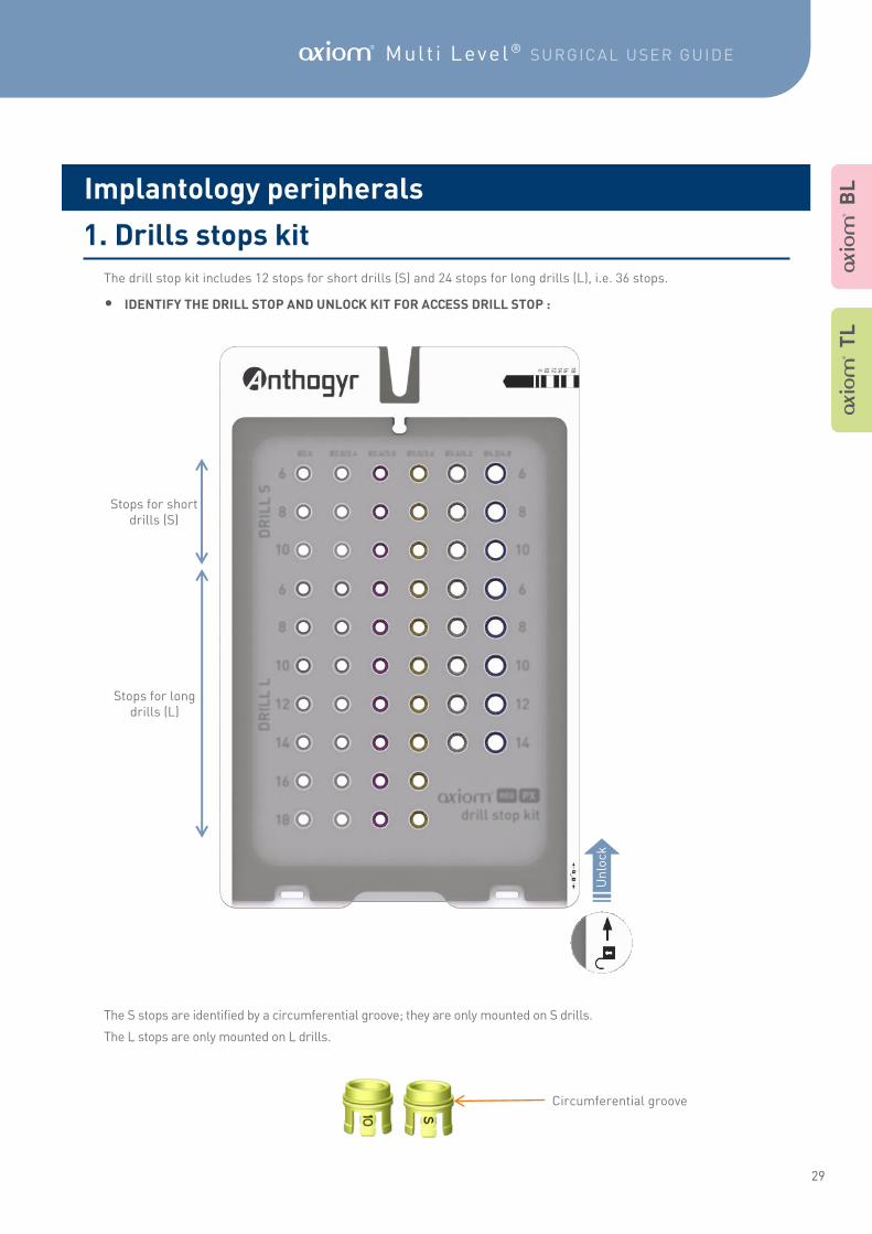
The drill stop kit includes 12 stops for short drills (S) and 24 stops for long drills (L), i.e. 36 stops.
• IDENTIFY THE DRILL STOP AND UNLOCK KIT FOR ACCESS DRILL STOP :
The S stops are identified by a circumferential groove; they are only mounted on S drills.
The L stops are only mounted on L drills.
Stops for short drills (S)
Stops for long drills (L)
Un
lock
Circumferential groove
A B
L
A T
L
Implantology peripherals
1. Drills stops kit
30
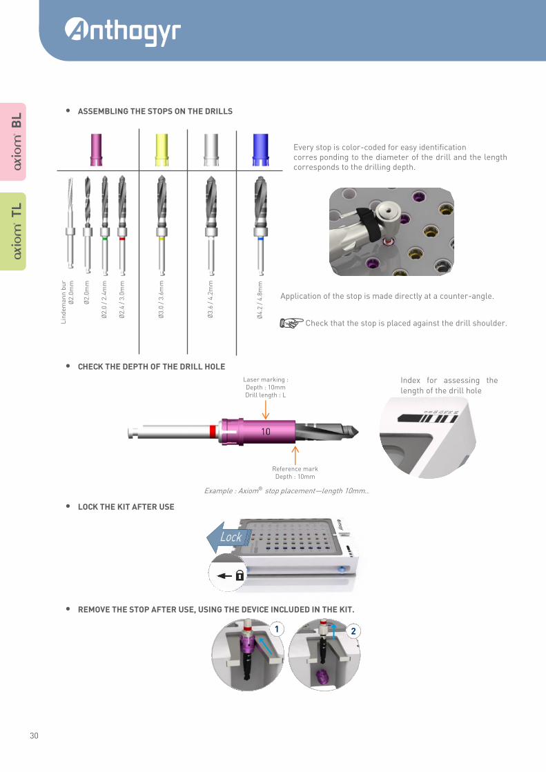
• ASSEMBLING THE STOPS ON THE DRILLS
Every stop is color-coded for easy identification corres ponding to the diameter of the drill and the length corresponds to the drilling depth.
Application of the stop is made directly at a counter-angle.
Check that the stop is placed against the drill shoulder.
• CHECK THE DEPTH OF THE DRILL HOLE
Example : Axiom® stop placement—length 10mm..
• LOCK THE KIT AFTER USE
• REMOVE THE STOP AFTER USE, USING THE DEVICE INCLUDED IN THE KIT.
U Lin
de
ma
nn
bu
r Ø
2.0
mm
Ø
2.0
mm
Ø
2.0
/ 2
.4m
m
Ø2
.4 /
3.0
mm
Ø3
.0 /
3.6
mm
Ø3
.6 /
4.2
mm
Ø4
.2 /
4.8
mm
Reference mark Depth : 10mm
Laser marking : Depth : 10mm Drill length : L
1 2
Index for assessing the
length of the drill hole
A T
L
A B
L
31
A Mult i Level ® SURGICAL USER GUIDE
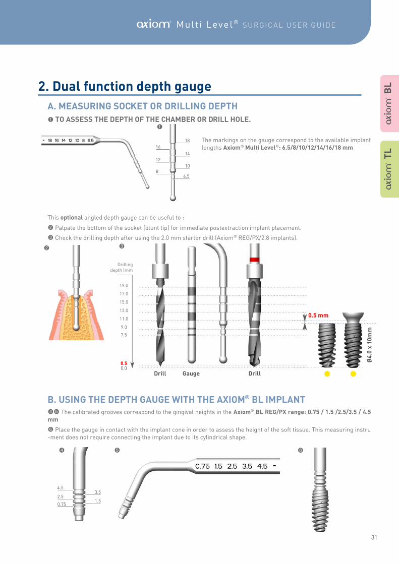
1 TO ASSESS THE DEPTH OF THE CHAMBER OR DRILL HOLE.
The markings on the gauge correspond to the available implant
lengths Axiom® Multi Level®: 6.5/8/10/12/14/16/18 mm
This optional angled depth gauge can be useful to :
2 Palpate the bottom of the socket (blunt tip) for immediate postextraction implant placement.
3 Check the drilling depth after using the 2.0 mm starter drill (Axiom® REG/PX/2.8 implants).
45 The calibrated grooves correspond to the gingival heights in the Axiom® BL REG/PX range: 0.75 / 1.5 /2.5/3.5 / 4.5
mm
6 Place the gauge in contact with the implant cone in order to assess the height of the soft tissue. This measuring instru
-ment does not require connecting the implant due to its cylindrical shape.
18
14
10
6.5
16
12
8
1
1.5
3.5 4.5
2.5
0.75
4 5 6
2 3
Drill Gauge Drill
Drilling depth (mm
0.5 0.0
7.5
9.0
11.0
13.0
15.0
17.0
19.0
Ø4
.0 x
10
mm
A B
L
A T
L
A. MEASURING SOCKET OR DRILLING DEPTH
2. Dual function depth gauge
0.5 mm
B. USING THE DEPTH GAUGE WITH THE AXIOM® BL IMPLANT

32
Set of 4 concave bayonet
osteotomes
Set of 4 convex bayonet
osteotomes SAFE impactor
Set of 4 straight concave
osteotomes
Tightening mandrel for the
Axiom® BL implant
Mandrel extension
Set of 4 straight convex
osteotomes
Universal surgical
screwdriver
Osteotomes can be used to prepare the site and implement the Axiom® BL implants.
The OSTEO SAFE® solution is designed for crestal sinus lifts and/or maxilla bone condensation in low density bone.
You will also find other information about how to use OSTEO SAFE® in the osteotome user guide. (063OSTEOTOMIE_NOT) Research code for the ifu.anthogyr.com web-site: INUSI D
A B
L
3. Osteotomy protocol
33
A Mult i Level ® SURGICAL USER GUIDE
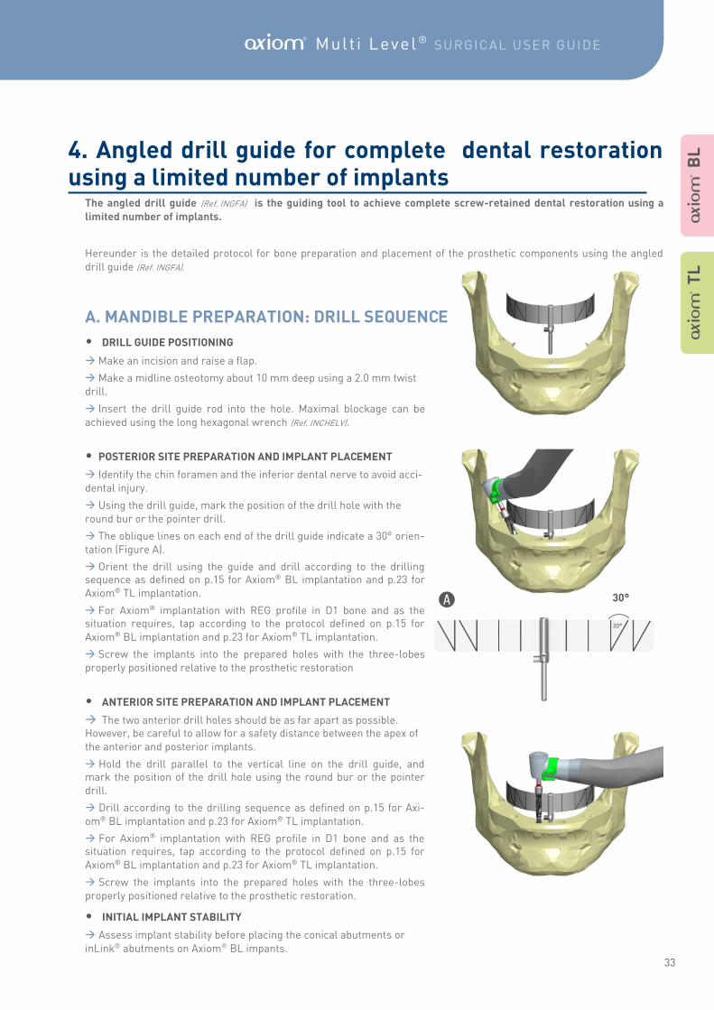
The angled drill guide (Ref. INGFA) is the guiding tool to achieve complete screw-retained dental restoration using a
limited number of implants.
Hereunder is the detailed protocol for bone preparation and placement of the prosthetic components using the angled
drill guide (Ref. INGFA).
• DRILL GUIDE POSITIONING
Make an incision and raise a flap.
Make a midline osteotomy about 10 mm deep using a 2.0 mm twist
drill.
Insert the drill guide rod into the hole. Maximal blockage can be
achieved using the long hexagonal wrench (Ref. INCHELV).
• POSTERIOR SITE PREPARATION AND IMPLANT PLACEMENT
Identify the chin foramen and the inferior dental nerve to avoid acci-
dental injury.
Using the drill guide, mark the position of the drill hole with the
round bur or the pointer drill.
The oblique lines on each end of the drill guide indicate a 30° orien-
tation (Figure A).
Orient the drill using the guide and drill according to the drilling sequence as defined on p.15 for Axiom® BL implantation and p.23 for
Axiom® TL implantation.
For Axiom® implantation with REG profile in D1 bone and as the situation requires, tap according to the protocol defined on p.15 for
Axiom® BL implantation and p.23 for Axiom® TL implantation.
Screw the implants into the prepared holes with the three-lobes
properly positioned relative to the prosthetic restoration
• ANTERIOR SITE PREPARATION AND IMPLANT PLACEMENT
The two anterior drill holes should be as far apart as possible. However, be careful to allow for a safety distance between the apex of
the anterior and posterior implants.
Hold the drill parallel to the vertical line on the drill guide, and mark the position of the drill hole using the round bur or the pointer
drill.
Drill according to the drilling sequence as defined on p.15 for Axi-
om® BL implantation and p.23 for Axiom® TL implantation.
For Axiom® implantation with REG profile in D1 bone and as the situation requires, tap according to the protocol defined on p.15 for
Axiom® BL implantation and p.23 for Axiom® TL implantation.
Screw the implants into the prepared holes with the three-lobes
properly positioned relative to the prosthetic restoration.
• INITIAL IMPLANT STABILITY
Assess implant stability before placing the conical abutments or
inLink® abutments on Axiom® BL impants.
A 30°
A B
L
A T
L
4. Angled drill guide for complete dental restoration using a limited number of implants
A. MANDIBLE PREPARATION: DRILL SEQUENCE
34
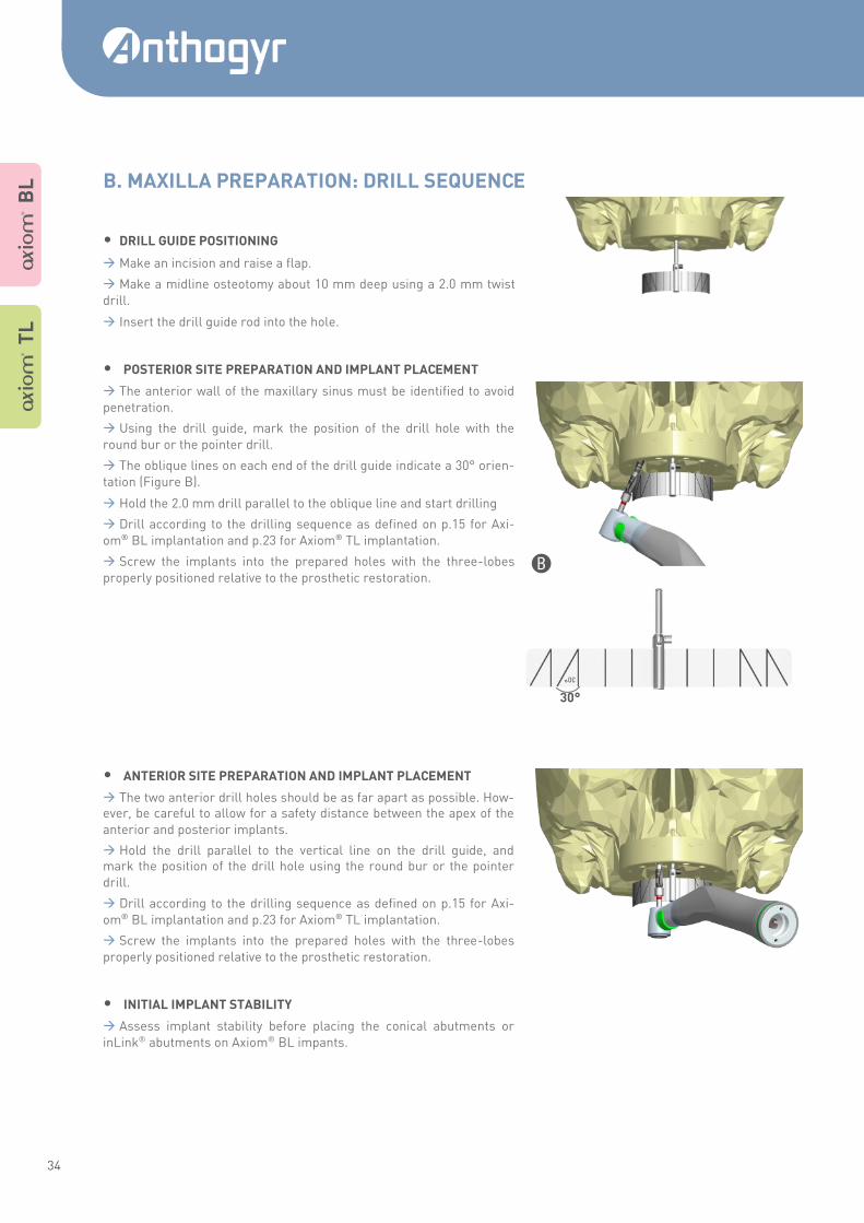
• DRILL GUIDE POSITIONING
Make an incision and raise a flap.
Make a midline osteotomy about 10 mm deep using a 2.0 mm twist
drill.
Insert the drill guide rod into the hole.
• POSTERIOR SITE PREPARATION AND IMPLANT PLACEMENT
The anterior wall of the maxillary sinus must be identified to avoid
penetration.
Using the drill guide, mark the position of the drill hole with the
round bur or the pointer drill.
The oblique lines on each end of the drill guide indicate a 30° orien-
tation (Figure B).
Hold the 2.0 mm drill parallel to the oblique line and start drilling
Drill according to the drilling sequence as defined on p.15 for Axi-
om® BL implantation and p.23 for Axiom® TL implantation.
Screw the implants into the prepared holes with the three-lobes
properly positioned relative to the prosthetic restoration.
• ANTERIOR SITE PREPARATION AND IMPLANT PLACEMENT
The two anterior drill holes should be as far apart as possible. How-ever, be careful to allow for a safety distance between the apex of the
anterior and posterior implants.
Hold the drill parallel to the vertical line on the drill guide, and mark the position of the drill hole using the round bur or the pointer
drill.
Drill according to the drilling sequence as defined on p.15 for Axi-
om® BL implantation and p.23 for Axiom® TL implantation.
Screw the implants into the prepared holes with the three-lobes
properly positioned relative to the prosthetic restoration.
• INITIAL IMPLANT STABILITY
Assess implant stability before placing the conical abutments or
inLink® abutments on Axiom® BL impants.
B
30°
A T
L
A B
L B. MAXILLA PREPARATION: DRILL SEQUENCE
35
A Mult i Level ® SURGICAL USER GUIDE
To clean and sterilise Anthogyr components, please refer to the sterilisation manual (063NETT-STE_NOT) Research code for the ifu.anthogyr.com web-site: INMODOPS3
The assembly and disassembly operations of the Anthogyr kits and ratchet wrench (Ref. INCC) are described in the sterili-
sation manual (063NETT-STE_NOT). Research code for the ifu.anthogyr.com web-site: INMODOPS3
For all other Anthogyr devices, please refer to their respective instructions for use.
D
D
A B
L
A T
L
Cleaning and sterilisation
Disassembling – Re-assembly
36
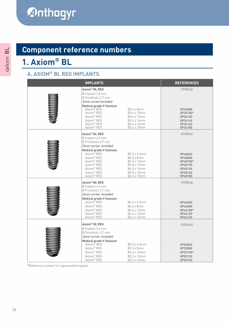
*Reference number for represented implant
IMPLANTS REFERENCES
Axiom® BL REG STERILE
Ø Implant 3.4 mm Ø Prosthetic 2.7 mm
Cover screw included
Medical grade V titanium Axiom® REG Ø3.4 x 8mm OP34080* Axiom® REG Ø3.4 x 10mm OP34100* Axiom® REG Ø3.4 x 12mm OP34120* Axiom® REG Ø3.4 x 14mm OP34140* Axiom® REG Ø3.4 x 16mm OP34160* Axiom® REG Ø3.4 x 18mm OP34180*
Axiom® BL REG STERILE Ø Implant 4.0 mm Ø Prosthetic 2.7 mm
Cover screw included
Medical grade V titanium
Axiom® REG Ø4.0 x 6.5mm OP40060* Axiom® REG Ø4.0 x 8mm OP40080* Axiom® REG Ø4.0 x 10mm OP40100* Axiom® REG Ø4.0 x 12mm OP40120* Axiom® REG Ø4.0 x 14mm OP40140* Axiom® REG Ø4.0 x 16mm OP40160* Axiom® REG Ø4.0 x 18mm OP40180*
Axiom® BL REG STERILE Ø Implant 4.6 mm Ø Prosthetic 2.7 mm
Cover screw included
Medical grade V titanium Axiom® REG Ø4.6 x 6.5mm OP46060* Axiom® REG Ø4.6 x 8mm OP46080* Axiom® REG Ø4.6 x 10mm OP46100* Axiom® REG Ø4.6 x 12mm OP46120* Axiom® REG Ø4.6 x 14mm OP46140*
Axiom® BL REG STERILE
Ø Implant 5.2 mm Ø Prosthetic 2.7 mm
Cover screw included
Medical grade V titanium Axiom® REG Ø5.2 x 6.5mm OP52060* Axiom® REG Ø5.2 x 8mm OP52080*
Axiom® REG Ø5.2 x 10mm OP52100*
Axiom® REG Ø5.2 x 12mm OP52120* Axiom® REG Ø5.2 x 14mm OP52140*
A B
L
1. Axiom® BL
A. AXIOM® BL REG IMPLANTS
Component reference numbers
37
A Mult i Level ® SURGICAL USER GUIDE
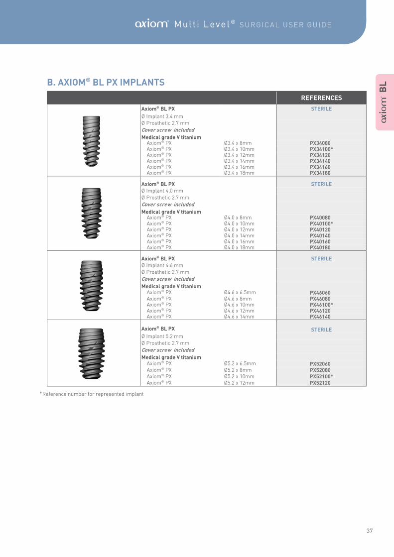
*Reference number for represented implant
REFERENCES
Axiom® BL PX STERILE
Ø Implant 3.4 mm Ø Prosthetic 2.7 mm
Cover screw included
Medical grade V titanium Axiom® PX Ø3.4 x 8mm PX34080* Axiom® PX Ø3.4 x 10mm PX34100* Axiom® PX Ø3.4 x 12mm PX34120* Axiom® PX Ø3.4 x 14mm PX34140* Axiom® PX Ø3.4 x 16mm PX34160* Axiom® PX Ø3.4 x 18mm PX34180*
Axiom® BL PX STERILE Ø Implant 4.0 mm
Ø Prosthetic 2.7 mm
Cover screw included
Medical grade V titanium Axiom® PX Ø4.0 x 8mm PX40080* Axiom® PX Ø4.0 x 10mm PX40100* Axiom® PX Ø4.0 x 12mm PX40120* Axiom® PX Ø4.0 x 14mm PX40140* Axiom® PX Ø4.0 x 16mm PX40160* Axiom® PX Ø4.0 x 18mm PX40180*
Axiom® BL PX STERILE Ø Implant 4.6 mm Ø Prosthetic 2.7 mm
Cover screw included
Medical grade V titanium Axiom® PX Ø4.6 x 6.5mm PX46060* Axiom® PX Ø4.6 x 8mm PX46080* Axiom® PX Ø4.6 x 10mm PX46100* Axiom® PX Ø4.6 x 12mm PX46120* Axiom® PX Ø4.6 x 14mm PX46140*
Axiom® BL PX STERILE
Ø Implant 5.2 mm Ø Prosthetic 2.7 mm
Cover screw included
Medical grade V titanium Axiom® PX Ø5.2 x 6.5mm PX52060* Axiom® PX Ø5.2 x 8mm PX52080* Axiom® PX Ø5.2 x 10mm PX52100* Axiom® PX Ø5.2 x 12mm PX52120*
A B
L B. AXIOM® BL PX IMPLANTS
38
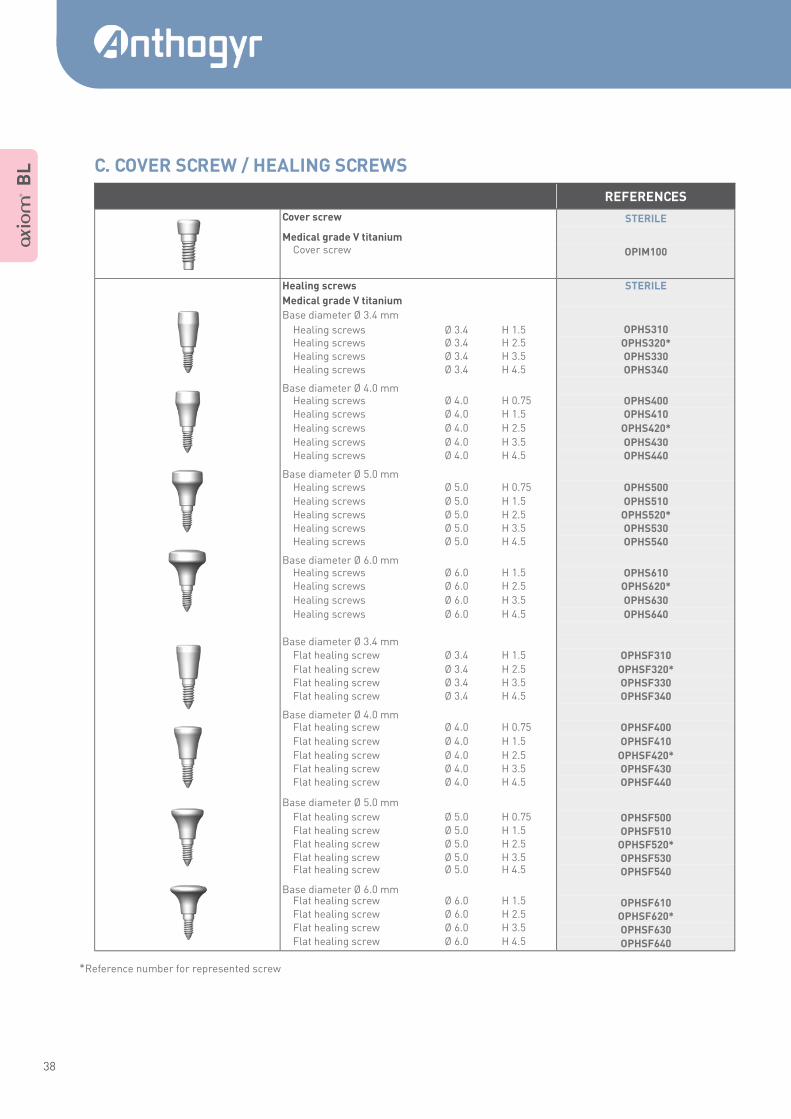
*Reference number for represented screw
REFERENCES
Cover screw STERILE
Medical grade V titanium
Cover screw
OPIM100
Healing screws STERILE
Medical grade V titanium
Base diameter Ø 3.4 mm
Healing screws Ø 3.4 H 1.5 OPHS310 Healing screws Ø 3.4 H 2.5 OPHS320* Healing screws Ø 3.4 H 3.5 OPHS330 Healing screws Ø 3.4 H 4.5 OPHS340
Base diameter Ø 4.0 mm
Healing screws Ø 4.0 H 0.75 OPHS400 Healing screws Ø 4.0 H 1.5 OPHS410
Healing screws Ø 4.0 H 2.5 OPHS420*
Healing screws Ø 4.0 H 3.5 OPHS430 Healing screws Ø 4.0 H 4.5 OPHS440
Base diameter Ø 5.0 mm
Healing screws Ø 5.0 H 0.75 OPHS500
Healing screws Ø 5.0 H 1.5 OPHS510 Healing screws Ø 5.0 H 2.5 OPHS520* Healing screws Ø 5.0 H 3.5 OPHS530 Healing screws Ø 5.0 H 4.5 OPHS540
Base diameter Ø 6.0 mm
Healing screws Ø 6.0 H 1.5 OPHS610 Healing screws Ø 6.0 H 2.5 OPHS620*
Healing screws Ø 6.0 H 3.5 OPHS630
Healing screws Ø 6.0 H 4.5 OPHS640
Base diameter Ø 3.4 mm Flat healing screw Ø 3.4 H 1.5 OPHSF310
Flat healing screw Ø 3.4 H 2.5 OPHSF320* Flat healing screw Ø 3.4 H 3.5 OPHSF330 Flat healing screw Ø 3.4 H 4.5 OPHSF340
Base diameter Ø 4.0 mm
Flat healing screw Ø 4.0 H 0.75 OPHSF400
Flat healing screw Ø 4.0 H 1.5 OPHSF410
Flat healing screw Ø 4.0 H 2.5 OPHSF420* Flat healing screw Ø 4.0 H 3.5 OPHSF430 Flat healing screw Ø 4.0 H 4.5 OPHSF440
Base diameter Ø 5.0 mm
Flat healing screw Ø 5.0 H 0.75 OPHSF500 Flat healing screw Ø 5.0 H 1.5 OPHSF510 Flat healing screw Ø 5.0 H 2.5 OPHSF520* Flat healing screw Ø 5.0 H 3.5 OPHSF530 Flat healing screw Ø 5.0 H 4.5 OPHSF540
Base diameter Ø 6.0 mm
Flat healing screw Ø 6.0 H 1.5 OPHSF610 Flat healing screw Ø 6.0 H 2.5 OPHSF620* Flat healing screw Ø 6.0 H 3.5 OPHSF630 Flat healing screw Ø 6.0 H 4.5 OPHSF640
A B
L C. COVER SCREW / HEALING SCREWS
39
A Mult i Level ® SURGICAL USER GUIDE
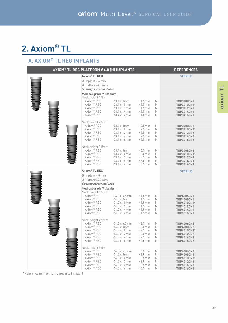
*Reference number for represented implant
AXIOM® TL REG PLATFORM Ø4.0 (N) IMPLANTS REFERENCES
Axiom® TL REG STERILE
Ø Implant 3.4 mm
Ø Platform 4.0 mm
Sealing screw included
Medical grade V titanium
Neck height 1.5mm Axiom® REG Ø3.4 x 8mm H1.5mm N TOP34080N1* Axiom® REG Ø3.4 x 10mm H1.5mm N TOP34100N1* Axiom® REG Ø3.4 x 12mm H1.5mm N TOP34120N1* Axiom® REG Ø3.4 x 14mm H1.5mm N TOP34140N1* Axiom® REG Ø3.4 x 16mm H1.5mm N TOP34160N1*
Neck height 2.5mm Axiom® REG Ø3.4 x 8mm H2.5mm N TOP34080N2* Axiom® REG Ø3.4 x 10mm H2.5mm N TOP34100N2* Axiom® REG Ø3.4 x 12mm H2.5mm N TOP34120N2* Axiom® REG Ø3.4 x 14mm H2.5mm N TOP34140N2* Axiom® REG Ø3.4 x 16mm H2.5mm N TOP34160N2*
Neck height 3.5mm Axiom® REG Ø3.4 x 8mm H3.5mm N TOP34080N3* Axiom® REG Ø3.4 x 10mm H3.5mm N TOP34100N3* Axiom® REG Ø3.4 x 12mm H3.5mm N TOP34120N3* Axiom® REG Ø3.4 x 14mm H3.5mm N TOP34140N3* Axiom® REG Ø3.4 x 16mm H3.5mm N TOP34160N3*
Axiom® TL REG STERILE
Ø Implant 4.0 mm
Ø Platform 4.0 mm
Sealing screw included
Medical grade V titanium
Neck height 1.5mm Axiom® REG Ø4.0 x 6.5mm H1.5mm N TOP40060N1* Axiom® REG Ø4.0 x 8mm H1.5mm N TOP40080N1* Axiom® REG Ø4.0 x 10mm H1.5mm N TOP40100N1* Axiom® REG Ø4.0 x 12mm H1.5mm N TOP40120N1* Axiom® REG Ø4.0 x 14mm H1.5mm N TOP40140N1* Axiom® REG Ø4.0 x 16mm H1.5mm N TOP40160N1*
Neck height 2.5mm Axiom® REG Ø4.0 x 6.5mm H2.5mm N TOP40060N2* Axiom® REG Ø4.0 x 8mm H2.5mm N TOP40080N2* Axiom® REG Ø4.0 x 10mm H2.5mm N TOP40100N2* Axiom® REG Ø4.0 x 12mm H2.5mm N TOP40120N2* Axiom® REG Ø4.0 x 14mm H2.5mm N TOP40140N2* Axiom® REG Ø4.0 x 16mm H2.5mm N TOP40160N2*
Neck height 3.5mm Axiom® REG Ø4.0 x 6.5mm H3.5mm N TOP40060N3* Axiom® REG Ø4.0 x 8mm H3.5mm N TOP40080N3* Axiom® REG Ø4.0 x 10mm H3.5mm N TOP40100N3* Axiom® REG Ø4.0 x 12mm H3.5mm N TOP40120N3* Axiom® REG Ø4.0 x 14mm H3.5mm N TOP40140N3* Axiom® REG Ø4.0 x 16mm H3.5mm N TOP40160N3*
A T
L
2. Axiom® TL
A. AXIOM® TL REG IMPLANTS
40
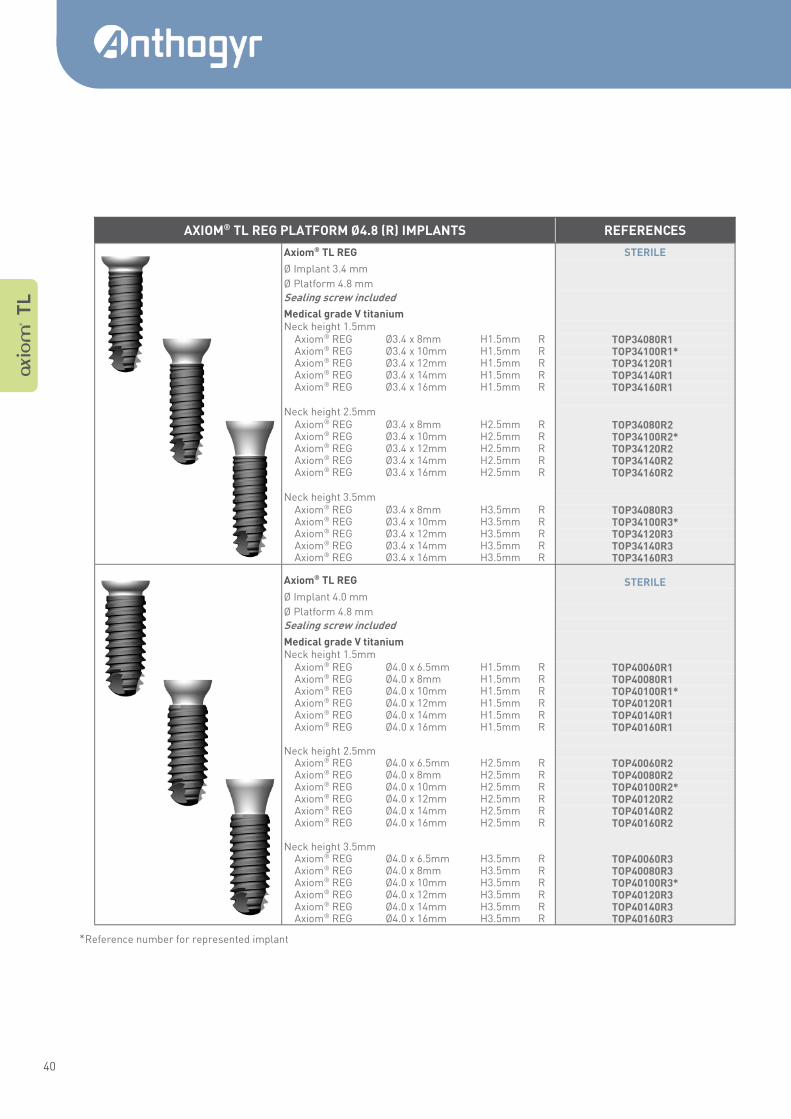
*Reference number for represented implant
A T
L
AXIOM® TL REG PLATFORM Ø4.8 (R) IMPLANTS REFERENCES
Axiom® TL REG STERILE
Ø Implant 3.4 mm
Ø Platform 4.8 mm
Sealing screw included
Medical grade V titanium
Neck height 1.5mm Axiom® REG Ø3.4 x 8mm H1.5mm R TOP34080R1* Axiom® REG Ø3.4 x 10mm H1.5mm R TOP34100R1* Axiom® REG Ø3.4 x 12mm H1.5mm R TOP34120R1* Axiom® REG Ø3.4 x 14mm H1.5mm R TOP34140R1* Axiom® REG Ø3.4 x 16mm H1.5mm R TOP34160R1*
Neck height 2.5mm Axiom® REG Ø3.4 x 8mm H2.5mm R TOP34080R2* Axiom® REG Ø3.4 x 10mm H2.5mm R TOP34100R2* Axiom® REG Ø3.4 x 12mm H2.5mm R TOP34120R2* Axiom® REG Ø3.4 x 14mm H2.5mm R TOP34140R2* Axiom® REG Ø3.4 x 16mm H2.5mm R TOP34160R2*
Neck height 3.5mm Axiom® REG Ø3.4 x 8mm H3.5mm R TOP34080R3* Axiom® REG Ø3.4 x 10mm H3.5mm R TOP34100R3* Axiom® REG Ø3.4 x 12mm H3.5mm R TOP34120R3* Axiom® REG Ø3.4 x 14mm H3.5mm R TOP34140R3* Axiom® REG Ø3.4 x 16mm H3.5mm R TOP34160R3*
Axiom® TL REG STERILE
Ø Implant 4.0 mm
Ø Platform 4.8 mm
Sealing screw included
Medical grade V titanium
Neck height 1.5mm Axiom® REG Ø4.0 x 6.5mm H1.5mm R TOP40060R1* Axiom® REG Ø4.0 x 8mm H1.5mm R TOP40080R1* Axiom® REG Ø4.0 x 10mm H1.5mm R TOP40100R1* Axiom® REG Ø4.0 x 12mm H1.5mm R TOP40120R1* Axiom® REG Ø4.0 x 14mm H1.5mm R TOP40140R1* Axiom® REG Ø4.0 x 16mm H1.5mm R TOP40160R1*
Neck height 2.5mm Axiom® REG Ø4.0 x 6.5mm H2.5mm R TOP40060R2* Axiom® REG Ø4.0 x 8mm H2.5mm R TOP40080R2* Axiom® REG Ø4.0 x 10mm H2.5mm R TOP40100R2* Axiom® REG Ø4.0 x 12mm H2.5mm R TOP40120R2* Axiom® REG Ø4.0 x 14mm H2.5mm R TOP40140R2* Axiom® REG Ø4.0 x 16mm H2.5mm R TOP40160R2*
Neck height 3.5mm Axiom® REG Ø4.0 x 6.5mm H3.5mm R TOP40060R3* Axiom® REG Ø4.0 x 8mm H3.5mm R TOP40080R3* Axiom® REG Ø4.0 x 10mm H3.5mm R TOP40100R3* Axiom® REG Ø4.0 x 12mm H3.5mm R TOP40120R3* Axiom® REG Ø4.0 x 14mm H3.5mm R TOP40140R3* Axiom® REG Ø4.0 x 16mm H3.5mm R TOP40160R3*
41
A Mult i Level ® SURGICAL USER GUIDE
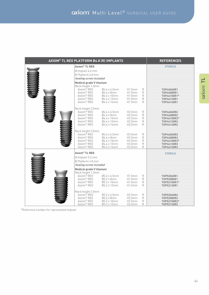
*Reference number for represented implant
A T
L
AXIOM® TL REG PLATFORM Ø4.8 (R) IMPLANTS REFERENCES
Axiom® TL REG STERILE
Ø Implant 4.6 mm
Ø Platform 4.8 mm
Sealing screw included
Medical grade V titanium
Neck height 1.5mm Axiom® REG Ø4.6 x 6.5mm H1.5mm R TOP46060R1* Axiom® REG Ø4.6 x 8mm H1.5mm R TOP46080R1* Axiom® REG Ø4.6 x 10mm H1.5mm R TOP46100R1* Axiom® REG Ø4.6 x 12mm H1.5mm R TOP46120R1* Axiom® REG Ø4.6 x 14mm H1.5mm R TOP46140R1*
Neck height 2.5mm Axiom® REG Ø4.6 x 6.5mm H2.5mm R TOP46060R2* Axiom® REG Ø4.6 x 8mm H2.5mm R TOP46080R2* Axiom® REG Ø4.6 x 10mm H2.5mm R TOP46100R2* Axiom® REG Ø4.6 x 12mm H2.5mm R TOP46120R2* Axiom® REG Ø4.6 x 14mm H2.5mm R TOP46140R2*
Neck height 3.5mm Axiom® REG Ø4.6 x 6.5mm H3.5mm R TOP46060R3* Axiom® REG Ø4.6 x 8mm H3.5mm R TOP46080R3* Axiom® REG Ø4.6 x 10mm H3.5mm R TOP46100R3* Axiom® REG Ø4.6 x 12mm H3.5mm R TOP46120R3* Axiom® REG Ø4.6 x 14mm H3.5mm R TOP46140R3*
Axiom® TL REG STERILE
Ø Implant 5.2 mm
Ø Platform 4.8 mm
Sealing screw included
Medical grade V titanium
Neck height 1.5mm Axiom® REG Ø5.2 x 6.5mm H1.5mm R TOP52060R1* Axiom® REG Ø5.2 x 8mm H1.5mm R TOP52080R1* Axiom® REG Ø5.2 x 10mm H1.5mm R TOP52100R1* Axiom® REG Ø5.2 x 12mm H1.5mm R TOP52120R1*
Neck height 2.5mm Axiom® REG Ø5.2 x 6.5mm H2.5mm R TOP52060R2* Axiom® REG Ø5.2 x 8mm H2.5mm R TOP52080R2* Axiom® REG Ø5.2 x 10mm H2.5mm R TOP52100R2* Axiom® REG Ø5.2 x 12mm H2.5mm R TOP52120R2*
42
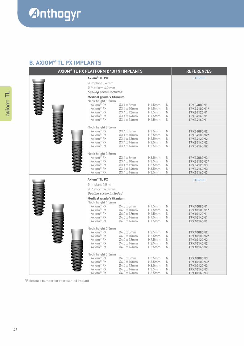
*Reference number for represented implant
A T
L
AXIOM® TL PX PLATFORM Ø4.0 (N) IMPLANTS REFERENCES
Axiom® TL PX STERILE
Ø Implant 3.4 mm
Ø Platform 4.0 mm
Sealing screw included
Medical grade V titanium
Neck height 1.5mm Axiom® PX Ø3.4 x 8mm H1.5mm N TPX34080N1* Axiom® PX Ø3.4 x 10mm H1.5mm N TPX34100N1* Axiom® PX Ø3.4 x 12mm H1.5mm N TPX34120N1* Axiom® PX Ø3.4 x 14mm H1.5mm N TPX34140N1* Axiom® PX Ø3.4 x 16mm H1.5mm N TPX34160N1*
Neck height 2.5mm Axiom® PX Ø3.4 x 8mm H2.5mm N TPX34080N2* Axiom® PX Ø3.4 x 10mm H2.5mm N TPX34100N2* Axiom® PX Ø3.4 x 12mm H2.5mm N TPX34120N2* Axiom® PX Ø3.4 x 14mm H2.5mm N TPX34140N2* Axiom® PX Ø3.4 x 16mm H2.5mm N TPX34160N2*
Neck height 3.5mm Axiom® PX Ø3.4 x 8mm H3.5mm N TPX34080N3* Axiom® PX Ø3.4 x 10mm H3.5mm N TPX34100N3* Axiom® PX Ø3.4 x 12mm H3.5mm N TPX34120N3* Axiom® PX Ø3.4 x 14mm H3.5mm N TPX34140N3* Axiom® PX Ø3.4 x 16mm H3.5mm N TPX34160N3*
Axiom® TL PX STERILE
Ø Implant 4.0 mm
Ø Platform 4.0 mm
Sealing screw included
Medical grade V titanium
Neck height 1.5mm Axiom® PX Ø4.0 x 8mm H1.5mm N TPX40080N1* Axiom® PX Ø4.0 x 10mm H1.5mm N TPX40100N1* Axiom® PX Ø4.0 x 12mm H1.5mm N TPX40120N1* Axiom® PX Ø4.0 x 14mm H1.5mm N TPX40140N1* Axiom® PX Ø4.0 x 16mm H1.5mm N TPX40160N1*
Neck height 2.5mm Axiom® PX Ø4.0 x 8mm H2.5mm N TPX40080N2* Axiom® PX Ø4.0 x 10mm H2.5mm N TPX40100N2* Axiom® PX Ø4.0 x 12mm H2.5mm N TPX40120N2* Axiom® PX Ø4.0 x 14mm H2.5mm N TPX40140N2* Axiom® PX Ø4.0 x 16mm H2.5mm N TPX40160N2*
Neck height 3.5mm Axiom® PX Ø4.0 x 8mm H3.5mm N TPX40080N3* Axiom® PX Ø4.0 x 10mm H3.5mm N TPX40100N3* Axiom® PX Ø4.0 x 12mm H3.5mm N TPX40120N3* Axiom® PX Ø4.0 x 14mm H3.5mm N TPX40140N3* Axiom® PX Ø4.0 x 16mm H3.5mm N TPX40160N3*
B. AXIOM® TL PX IMPLANTS
43
A Mult i Level ® SURGICAL USER GUIDE
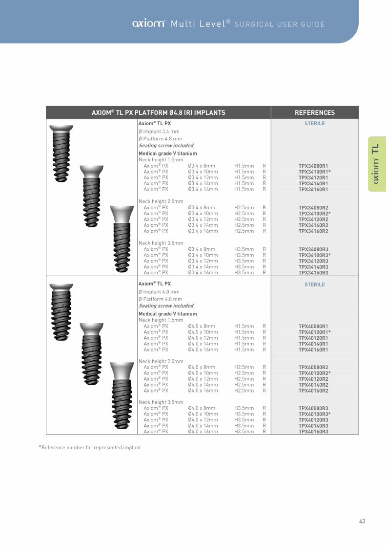
*Reference number for represented implant
A T
L
AXIOM® TL PX PLATFORM Ø4.8 (R) IMPLANTS REFERENCES
Axiom® TL PX STERILE
Ø Implant 3.4 mm
Ø Platform 4.8 mm
Sealing screw included
Medical grade V titanium
Neck height 1.5mm Axiom® PX Ø3.4 x 8mm H1.5mm R TPX34080R1* Axiom® PX Ø3.4 x 10mm H1.5mm R TPX34100R1* Axiom® PX Ø3.4 x 12mm H1.5mm R TPX34120R1* Axiom® PX Ø3.4 x 14mm H1.5mm R TPX34140R1* Axiom® PX Ø3.4 x 16mm H1.5mm R TPX34160R1*
Neck height 2.5mm Axiom® PX Ø3.4 x 8mm H2.5mm R TPX34080R2* Axiom® PX Ø3.4 x 10mm H2.5mm R TPX34100R2* Axiom® PX Ø3.4 x 12mm H2.5mm R TPX34120R2* Axiom® PX Ø3.4 x 14mm H2.5mm R TPX34140R2* Axiom® PX Ø3.4 x 16mm H2.5mm R TPX34160R2*
Neck height 3.5mm Axiom® PX Ø3.4 x 8mm H3.5mm R TPX34080R3* Axiom® PX Ø3.4 x 10mm H3.5mm R TPX34100R3* Axiom® PX Ø3.4 x 12mm H3.5mm R TPX34120R3* Axiom® PX Ø3.4 x 14mm H3.5mm R TPX34140R3* Axiom® PX Ø3.4 x 16mm H3.5mm R TPX34160R3*
Axiom® TL PX STERILE
Ø Implant 4.0 mm
Ø Platform 4.8 mm
Sealing screw included
Medical grade V titanium
Neck height 1.5mm Axiom® PX Ø4.0 x 8mm H1.5mm R TPX40080R1* Axiom® PX Ø4.0 x 10mm H1.5mm R TPX40100R1* Axiom® PX Ø4.0 x 12mm H1.5mm R TPX40120R1* Axiom® PX Ø4.0 x 14mm H1.5mm R TPX40140R1* Axiom® PX Ø4.0 x 16mm H1.5mm R TPX40160R1*
Neck height 2.5mm Axiom® PX Ø4.0 x 8mm H2.5mm R TPX40080R2* Axiom® PX Ø4.0 x 10mm H2.5mm R TPX40100R2* Axiom® PX Ø4.0 x 12mm H2.5mm R TPX40120R2* Axiom® PX Ø4.0 x 14mm H2.5mm R TPX40140R2* Axiom® PX Ø4.0 x 16mm H2.5mm R TPX40160R2*
Neck height 3.5mm Axiom® PX Ø4.0 x 8mm H3.5mm R TPX40080R3* Axiom® PX Ø4.0 x 10mm H3.5mm R TPX40100R3* Axiom® PX Ø4.0 x 12mm H3.5mm R TPX40120R3* Axiom® PX Ø4.0 x 14mm H3.5mm R TPX40140R3* Axiom® PX Ø4.0 x 16mm H3.5mm R TPX40160R3*
44
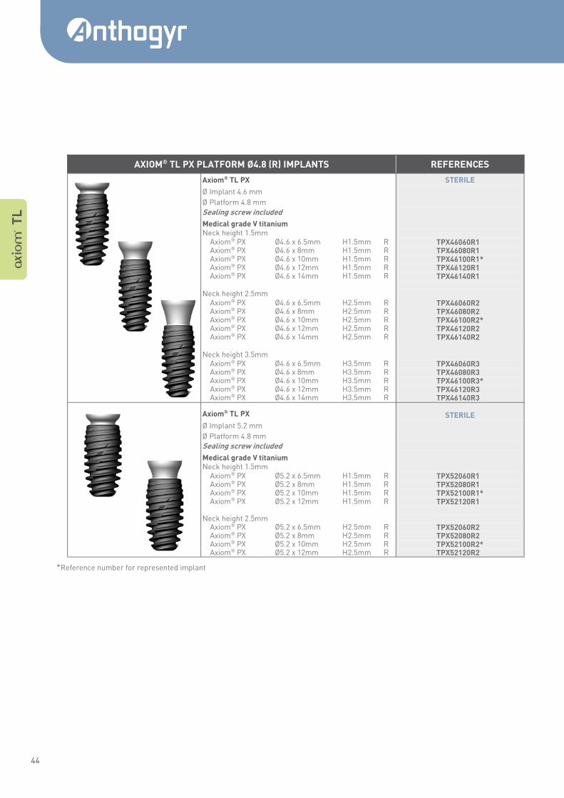
*Reference number for represented implant
A T
L
AXIOM® TL PX PLATFORM Ø4.8 (R) IMPLANTS REFERENCES
Axiom® TL PX STERILE
Ø Implant 4.6 mm
Ø Platform 4.8 mm
Sealing screw included
Medical grade V titanium
Neck height 1.5mm Axiom® PX Ø4.6 x 6.5mm H1.5mm R TPX46060R1* Axiom® PX Ø4.6 x 8mm H1.5mm R TPX46080R1* Axiom® PX Ø4.6 x 10mm H1.5mm R TPX46100R1* Axiom® PX Ø4.6 x 12mm H1.5mm R TPX46120R1* Axiom® PX Ø4.6 x 14mm H1.5mm R TPX46140R1*
Neck height 2.5mm Axiom® PX Ø4.6 x 6.5mm H2.5mm R TPX46060R2* Axiom® PX Ø4.6 x 8mm H2.5mm R TPX46080R2* Axiom® PX Ø4.6 x 10mm H2.5mm R TPX46100R2* Axiom® PX Ø4.6 x 12mm H2.5mm R TPX46120R2* Axiom® PX Ø4.6 x 14mm H2.5mm R TPX46140R2*
Neck height 3.5mm Axiom® PX Ø4.6 x 6.5mm H3.5mm R TPX46060R3* Axiom® PX Ø4.6 x 8mm H3.5mm R TPX46080R3* Axiom® PX Ø4.6 x 10mm H3.5mm R TPX46100R3* Axiom® PX Ø4.6 x 12mm H3.5mm R TPX46120R3* Axiom® PX Ø4.6 x 14mm H3.5mm R TPX46140R3*
Axiom® TL PX STERILE
Ø Implant 5.2 mm
Ø Platform 4.8 mm
Sealing screw included
Medical grade V titanium
Neck height 1.5mm Axiom® PX Ø5.2 x 6.5mm H1.5mm R TPX52060R1* Axiom® PX Ø5.2 x 8mm H1.5mm R TPX52080R1* Axiom® PX Ø5.2 x 10mm H1.5mm R TPX52100R1* Axiom® PX Ø5.2 x 12mm H1.5mm R TPX52120R1*
Neck height 2.5mm Axiom® PX Ø5.2 x 6.5mm H2.5mm R TPX52060R2* Axiom® PX Ø5.2 x 8mm H2.5mm R TPX52080R2* Axiom® PX Ø5.2 x 10mm H2.5mm R TPX52100R2* Axiom® PX Ø5.2 x 12mm H2.5mm R TPX52120R2*
45
A Mult i Level ® SURGICAL USER GUIDE
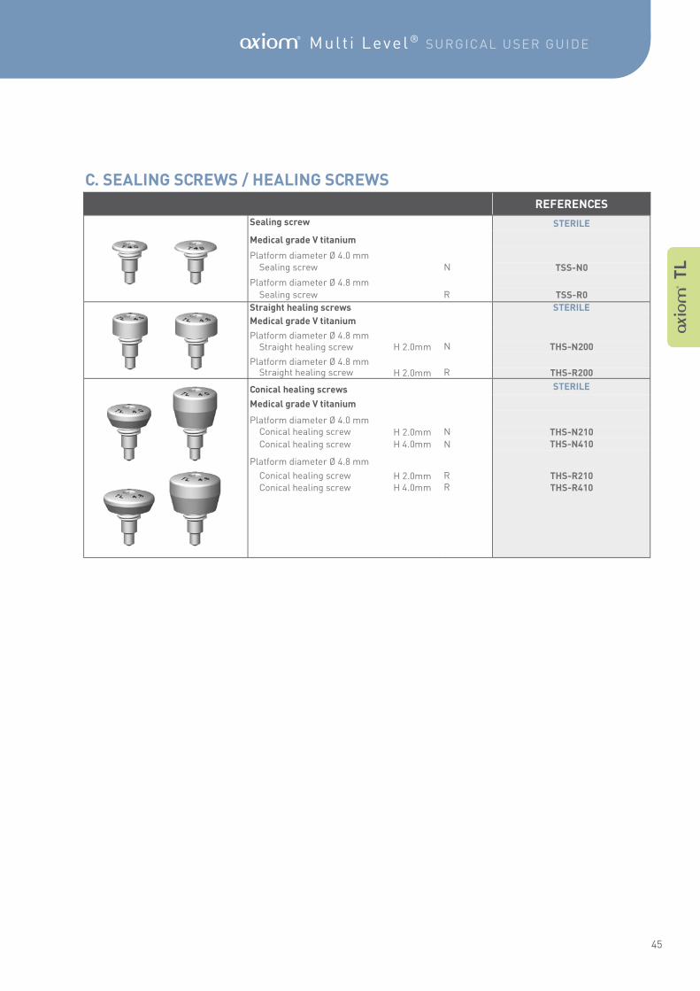
REFERENCES
Sealing screw STERILE
Medical grade V titanium
Platform diameter Ø 4.0 mm
Sealing screw N TSS-N0
Platform diameter Ø 4.8 mm
Sealing screw R TSS-R0
Straight healing screws STERILE
Medical grade V titanium
Platform diameter Ø 4.8 mm
Straight healing screw H 2.0mm N THS-N200
Platform diameter Ø 4.8 mm
Straight healing screw H 2.0mm R THS-R200
Conical healing screws STERILE
Medical grade V titanium
Platform diameter Ø 4.0 mm
Conical healing screw H 2.0mm N THS-N210
Conical healing screw H 4.0mm N THS-N410
Platform diameter Ø 4.8 mm
Conical healing screw H 2.0mm R THS-R210 Conical healing screw H 4.0mm R THS-R410
A T
L
C. SEALING SCREWS / HEALING SCREWS
46
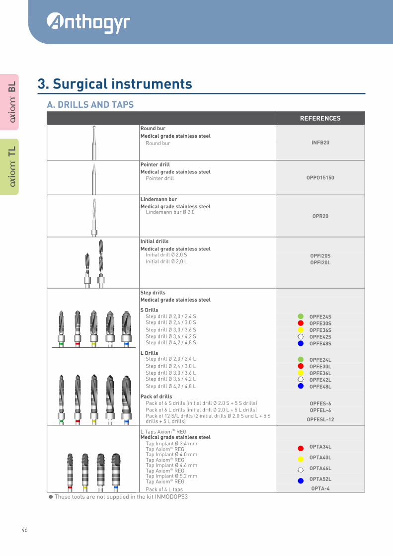
REFERENCES
Round bur
INFB20 Medical grade stainless steel
Round bur
Pointer drill
OPPO15150 Medical grade stainless steel Pointer drill
Lindemann bur
OPR20
Medical grade stainless steel Lindemann bur Ø 2,0
Initial drills
Medical grade stainless steel Initial drill Ø 2,0 S OPFI20S Initial drill Ø 2,0 L OPFI20L
Step drills
Medical grade stainless steel
S Drills
Step drill Ø 2,0 / 2.4 S OPFE24S Step drill Ø 2,4 / 3.0 S OPFE30S Step drill Ø 3,0 / 3,6 S OPFE36S Step drill Ø 3,6 / 4,2 S OPFE42S Step drill Ø 4,2 / 4,8 S OPFE48S
L Drills
Step drill Ø 2,0 / 2.4 L OPFE24L Step drill Ø 2,4 / 3.0 L OPFE30L Step drill Ø 3,0 / 3,6 L OPFE36L Step drill Ø 3,6 / 4,2 L OPFE42L Step drill Ø 4,2 / 4,8 L OPFE48L
Pack of drills
Pack of 6 S drills (initial drill Ø 2.0 S + 5 S drills) OPFES-6 Pack of 6 L drills (initial drill Ø 2.0 L + 5 L drills) OPFEL-6 Pack of 12 S/L drills (2 initial drills Ø 2.0 S and L + 5 S drills + 5 L drills) OPFESL-12
L Taps Axiom® REG
Medical grade stainless steel Tap Implant Ø 3.4 mm Tap Axiom® REG OPTA34L
Tap Implant Ø 4.0 mm Tap Axiom® REG OPTA40L
Tap Implant Ø 4.6 mm Tap Axiom® REG OPTA46L
Tap Implant Ø 5.2 mm Tap Axiom® REG OPTA52L
Pack of 4 L taps OPTA-4
A T
L
A B
L
These tools are not supplied in the kit INMODOPS3
3. Surgical instruments
A. DRILLS AND TAPS
47
A Mult i Level ® SURGICAL USER GUIDE
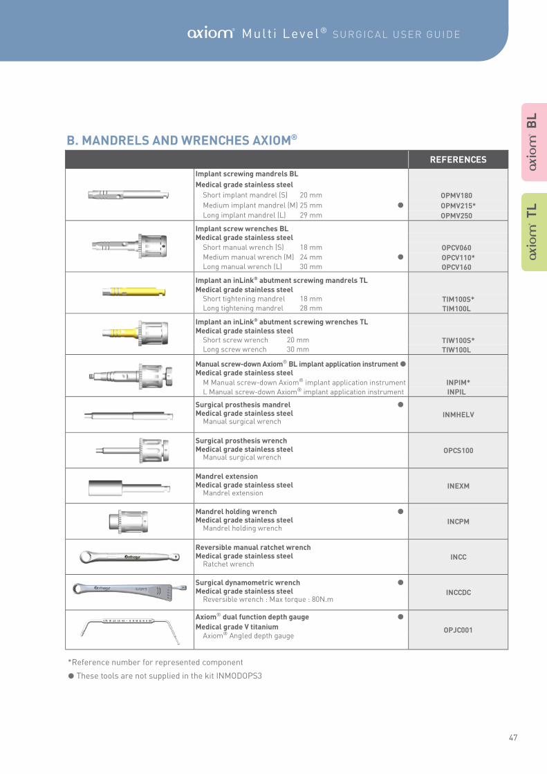
REFERENCES
Implant screwing mandrels BL
Medical grade stainless steel
Short implant mandrel (S) 20 mm OPMV180*
Medium implant mandrel (M) 25 mm OPMV215*
Long implant mandrel (L) 29 mm OPMV250*
Implant screw wrenches BL
Medical grade stainless steel
Short manual wrench (S) 18 mm OPCV060*
Medium manual wrench (M) 24 mm OPCV110* Long manual wrench (L) 30 mm OPCV160*
Implant an inLink® abutment screwing mandrels TL
Medical grade stainless steel Short tightening mandrel 18 mm TIM100S* Long tightening mandrel 28 mm TIM100L*
Implant an inLink® abutment screwing wrenches TL
Medical grade stainless steel Short screw wrench 20 mm TIW100S* Long screw wrench 30 mm TIW100L*
Manual screw-down Axiom® BL implant application instrument Medical grade stainless steel
M Manual screw-down Axiom® implant application instrument INPIM*
L Manual screw-down Axiom® implant application instrument INPIL*
Surgical prosthesis mandrel
INMHELV Medical grade stainless steel Manual surgical wrench
Surgical prosthesis wrench
OPCS100 Medical grade stainless steel Manual surgical wrench
Mandrel extension
INEXM Medical grade stainless steel Mandrel extension
Mandrel holding wrench
INCPM Medical grade stainless steel Mandrel holding wrench
Reversible manual ratchet wrench
INCC Medical grade stainless steel Ratchet wrench
Surgical dynamometric wrench
INCCDC Medical grade stainless steel Reversible wrench : Max torque : 80N.m
Axiom® dual function depth gauge
OPJC001 Medical grade V titanium Axiom® Angled depth gauge
A B
L
A T
L
*Reference number for represented component
These tools are not supplied in the kit INMODOPS3
B. MANDRELS AND WRENCHES AXIOM®
48
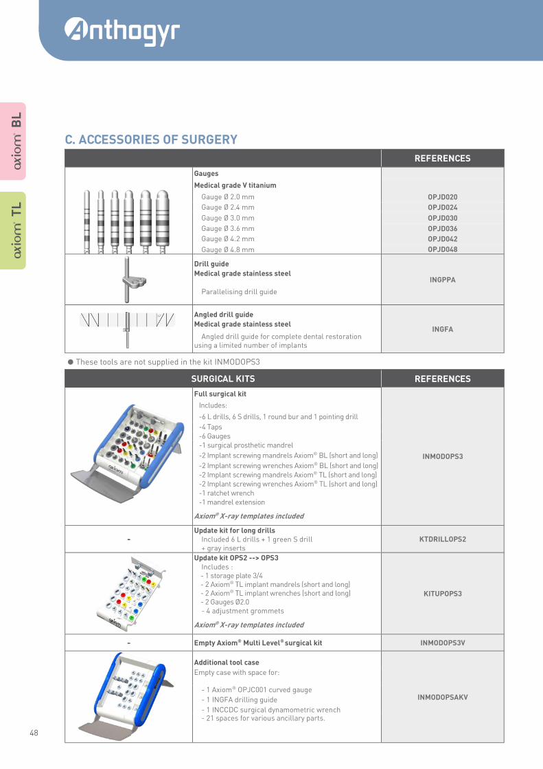
REFERENCES
Gauges
Medical grade V titanium
Gauge Ø 2.0 mm OPJD020
Gauge Ø 2.4 mm OPJD024
Gauge Ø 3.0 mm OPJD030
Gauge Ø 3.6 mm OPJD036
Gauge Ø 4.2 mm OPJD042
Gauge Ø 4.8 mm OPJD048
Drill guide
INGPPA Medical grade stainless steel
Parallelising drill guide
Angled drill guide
INGFA Medical grade stainless steel
Angled drill guide for complete dental restoration using a limited number of implants
SURGICAL KITS REFERENCES
Full surgical kit
INMODOPS3
Includes:
-6 L drills, 6 S drills, 1 round bur and 1 pointing drill
-4 Taps
-6 Gauges -1 surgical prosthetic mandrel
-2 Implant screwing mandrels Axiom® BL (short and long)
-2 Implant screwing wrenches Axiom® BL (short and long)
-2 Implant screwing mandrels Axiom® TL (short and long) -2 Implant screwing wrenches Axiom® TL (short and long) -1 ratchet wrench -1 mandrel extension
Axiom® X-ray templates included
- Update kit for long drills
KTDRILLOPS2 Included 6 L drills + 1 green S drill + gray inserts
Update kit OPS2 --> OPS3
KITUPOPS3
Includes : - 1 storage plate 3/4 - 2 Axiom® TL implant mandrels (short and long) - 2 Axiom® TL implant wrenches (short and long) - 2 Gauges Ø2.0 - 4 adjustment grommets
Axiom® X-ray templates included
- Empty Axiom® Multi Level® surgical kit INMODOPS3V
Additional tool case
INMODOPSAKV
Empty case with space for:
- 1 Axiom® OPJC001 curved gauge
- 1 INGFA drilling guide
- 1 INCCDC surgical dynamometric wrench - 21 spaces for various ancillary parts.
A T
L
A B
L
These tools are not supplied in the kit INMODOPS3
C. ACCESSORIES OF SURGERY
49
A Mult i Level ® SURGICAL USER GUIDE
A B
L
A T
L
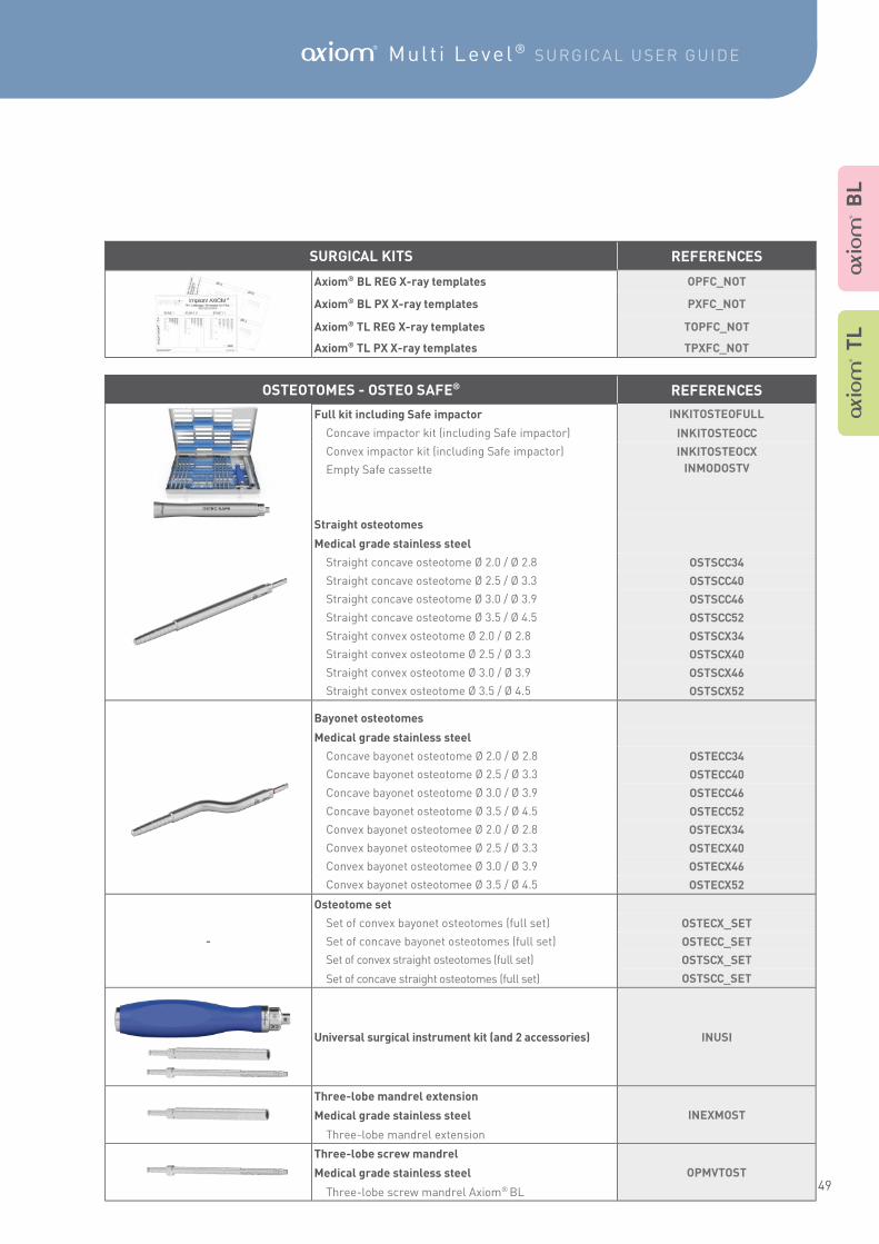
SURGICAL KITS REFERENCES
Axiom® BL REG X-ray templates OPFC_NOT
Axiom® BL PX X-ray templates PXFC_NOT
Axiom® TL REG X-ray templates TOPFC_NOT
Axiom® TL PX X-ray templates TPXFC_NOT
OSTEOTOMES - OSTEO SAFE® REFERENCES
Full kit including Safe impactor INKITOSTEOFULL
Concave impactor kit (including Safe impactor) INKITOSTEOCC
Convex impactor kit (including Safe impactor) INKITOSTEOCX
Empty Safe cassette INMODOSTV
Straight osteotomes
Medical grade stainless steel
Straight concave osteotome Ø 2.0 / Ø 2.8 OSTSCC34
Straight concave osteotome Ø 2.5 / Ø 3.3 OSTSCC40
Straight concave osteotome Ø 3.0 / Ø 3.9 OSTSCC46
Straight concave osteotome Ø 3.5 / Ø 4.5 OSTSCC52
Straight convex osteotome Ø 2.0 / Ø 2.8 OSTSCX34
Straight convex osteotome Ø 2.5 / Ø 3.3 OSTSCX40
Straight convex osteotome Ø 3.0 / Ø 3.9 OSTSCX46
Straight convex osteotome Ø 3.5 / Ø 4.5 OSTSCX52
Bayonet osteotomes
Medical grade stainless steel
Concave bayonet osteotome Ø 2.0 / Ø 2.8 OSTECC34
Concave bayonet osteotome Ø 2.5 / Ø 3.3 OSTECC40
Concave bayonet osteotome Ø 3.0 / Ø 3.9 OSTECC46
Concave bayonet osteotome Ø 3.5 / Ø 4.5 OSTECC52
Convex bayonet osteotomee Ø 2.0 / Ø 2.8 OSTECX34
Convex bayonet osteotomee Ø 2.5 / Ø 3.3 OSTECX40
Convex bayonet osteotomee Ø 3.0 / Ø 3.9 OSTECX46
Convex bayonet osteotomee Ø 3.5 / Ø 4.5 OSTECX52
-
Osteotome set
Set of convex bayonet osteotomes (full set) OSTECX_SET
Set of concave bayonet osteotomes (full set) OSTECC_SET
Set of convex straight osteotomes (full set) OSTSCX_SET
Set of concave straight osteotomes (full set) OSTSCC_SET
Universal surgical instrument kit (and 2 accessories) INUSI
Three-lobe mandrel extension
INEXMOST Medical grade stainless steel
Three-lobe mandrel extension
Three-lobe screw mandrel
OPMVTOST Medical grade stainless steel
Three-lobe screw mandrel Axiom® BL
50
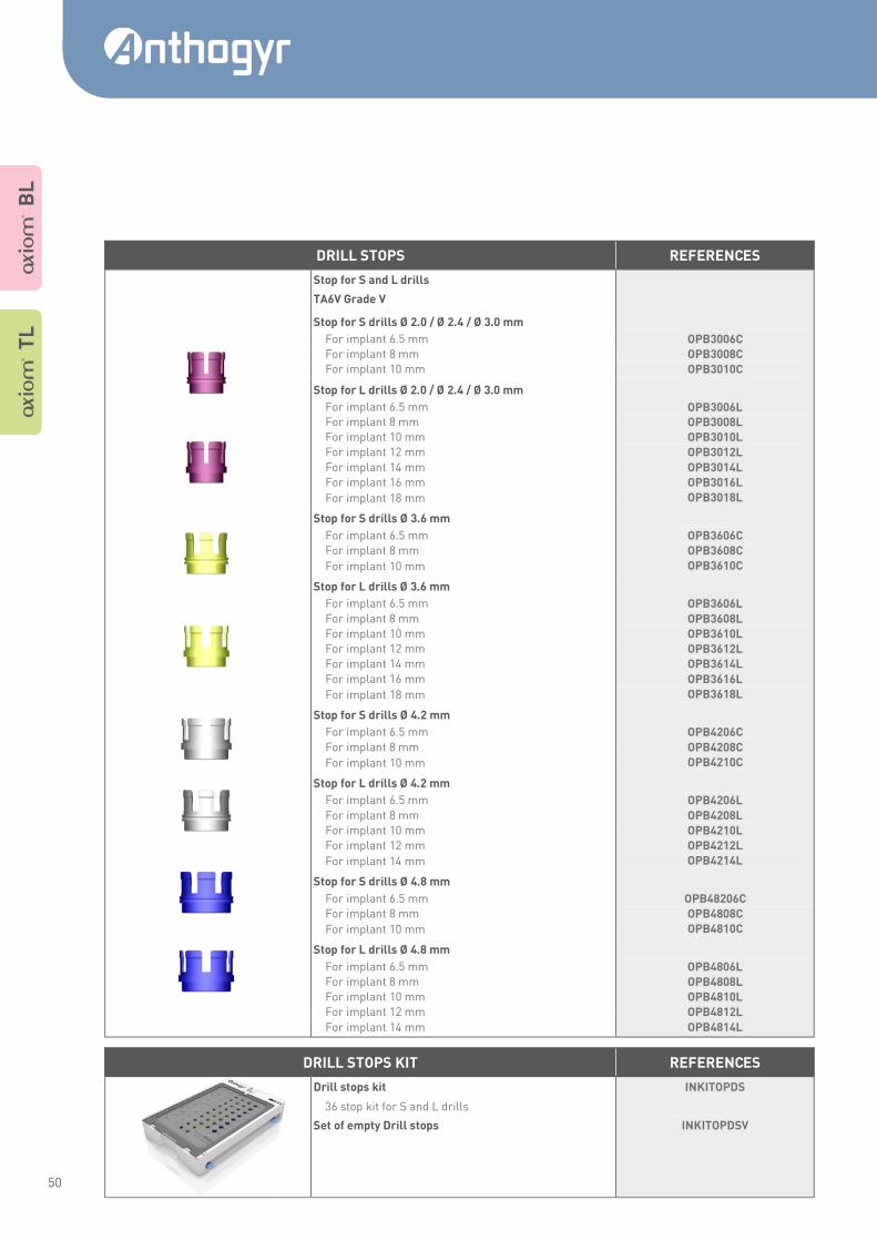
DRILL STOPS REFERENCES
Stop for S and L drills
TA6V Grade V
Stop for S drills Ø 2.0 / Ø 2.4 / Ø 3.0 mm
For implant 6.5 mm OPB3006C
For implant 8 mm OPB3008C
For implant 10 mm OPB3010C
Stop for L drills Ø 2.0 / Ø 2.4 / Ø 3.0 mm
For implant 6.5 mm OPB3006L For implant 8 mm OPB3008L
For implant 10 mm OPB3010L
For implant 12 mm OPB3012L
For implant 14 mm OPB3014L
For implant 16 mm OPB3016L
For implant 18 mm OPB3018L
Stop for S drills Ø 3.6 mm
For implant 6.5 mm OPB3606C
For implant 8 mm OPB3608C
For implant 10 mm OPB3610C
Stop for L drills Ø 3.6 mm
For implant 6.5 mm OPB3606L
For implant 8 mm OPB3608L
For implant 10 mm OPB3610L
For implant 12 mm OPB3612L
For implant 14 mm OPB3614L
For implant 16 mm OPB3616L
For implant 18 mm OPB3618L
Stop for S drills Ø 4.2 mm
For implant 6.5 mm OPB4206C
For implant 8 mm OPB4208C
For implant 10 mm OPB4210C
Stop for L drills Ø 4.2 mm
For implant 6.5 mm OPB4206L
For implant 8 mm OPB4208L
For implant 10 mm OPB4210L
For implant 12 mm OPB4212L
For implant 14 mm OPB4214L
Stop for S drills Ø 4.8 mm
For implant 6.5 mm OPB48206C
For implant 8 mm OPB4808C
For implant 10 mm OPB4810C
Stop for L drills Ø 4.8 mm
For implant 6.5 mm OPB4806L
For implant 8 mm OPB4808L
For implant 10 mm OPB4810L
For implant 12 mm OPB4812L
For implant 14 mm OPB4814L
DRILL STOPS KIT REFERENCES
Drill stops kit INKITOPDS
36 stop kit for S and L drills
Set of empty Drill stops INKITOPDSV
A T
L
A B
L
51
A Mult i Level ® SURGICAL USER GUIDE
NOTE
Anthogyr SAS 2 237, Avenue André Lasquin 74700 Sallanches - France Tél. +33 (0)4 50 58 02 37 Fax +33 (0)4 50 93 78 60
www.anthogyr.com
Ph
oto
s cr
ed
its
: A
nth
og
yr -
All
rig
hts
re
serv
ed
- N
ot
con
tra
ctu
al
ph
oto
s
A
XIO
M-M
LC
_N
OT
_G
B 2
01
7-0
4