Embed Size (px)
Citation preview
Surgical Technique Guide
Bristow-LatarjetInstabilityShoulderSystemOpenandArthroscopicTechniques

2
a leTTer from dr. lafosse
Dear friends,
shoulder instability has been treated differently with time evolution. We know that soft
tissue repair is not always effective for shoulder stabilization. A new arthroscopic concept
of shoulder bone block stabilization has been developed on the base of the Latarjet
procedure to hit the advantages of both techniques. Let me give you my beliefs on
this procedure:
Why a Latarjet procedure?
in 1954, Dr. m Latarjet1 described his technique of transferring the horizontal part of the coracoid to the anterior inferior margin of the glenoid from the 2 o’clock to the 6 o’clock position. the original procedure required detachment of the upper part of the subscapularis, but this has since been modified to place the graft through a horizontal split in the subscapularis and affix it to the glenoid with 2 screws.
Patte et al2 explained the success of the open Latarjet procedure by virtue of the triple-blocking effect. We interpret the triple-block effect first by the bony reconstruction of the anterior glenoid, which serves to increase the glenoid articular arc. this prevents an otherwise engaging hill-sachs lesion from levering on the potentially deficient anteroinferior glenoid rim.
secondly, the split of the subscapularis tendon provides dynamic stability in abduction and external rotation due to the tension created by its intersection with the newly positioned conjoint tendon.
the sling effect of the conjoint tendon crossing the subscapularis has a significant effect on the stability of the shoulder in external rotation after 90° of abduction as it has been proven by biomechanical studies.
Why an arthroscopic Latarjet?
the natural evolution of this procedure was to develop an all-arthroscopic technique that captures all of the advantages of the open procedure while using a minimally invasive technique.
since December 2003, we have performed over 300 arthroscopic Latarjet procedures. the all-arthroscopic Latarjet is a reliable but difficult technique, with a steep learning curve.
our technique has shown excellent results through midterm follow-up, with minimal complications and good graft positioning. We recommend the arthroscopic procedure to surgeons who have good anatomic knowledge, advanced arthroscopic skills, and familiarity with the instrumentation.
Despite the success of open Latarjet procedure, the arthroscopic Latarjet holds many advantages, including:
1. Placement of the bone graft is more accurate under arthroscopic control.several different views can be afforded by the arthroscopic technique that improve graft placement and reduce the chances of overhang and impingement.
3
s U r G I C a l T e C H n I Q U e G U I d e
1. Latarjet M. [Treatment of recurrent dislocation of the shoulder.]. LyonChir 1954;49:994-7.2. Patte D, Bernageau J, Bancel P. The anteroinferior vulnerable point of
the glenoid rim. New York: Marcel Dekker; 1985.
2. open surgery does not easily allow the treatment of concomitant pathologies such as sLAPtears and posterior labral lesions.
3. concurrent anterior and posterior instability can be treated during the same arthroscopicsurgical procedure using anterior and posterior bone blocks. this is not possible through a single open approach.
4. the risk of adhesions and shoulder stiffness is higher with an open technique than with arthroscopy.
5. if during an intended Bankart repair the tissue is determined to not be reconstructable, thenan arthroscopic Latarjet offers an alternative to traditional open surgery without potentially having to reposition the patient.
6. As in other joints, arthroscopy offers the postoperative advantages of less pain, earliermobility, quicker rehabilitation and faster return to sports.
7. An all-arthroscopic technique offers the patient an improved cosmetic result.
8. Arthroscopy reveals many previously unrecognized soft tissue and bony lesions underlyingrecurrent anterior shoulder instability.
How to manage the procedure
We recommend the use of the instrumentation for open Latarjet as it provides a reproducible and guided technique.
it is important to be familiar with the technique by starting with an open approach, but to begin doing this using the arthroscopic instrumentation set.
once the surgeon is familiar with these instruments, he or she can begin the first stage of the surgery arthroscopically.
After this first stage is completed, the rest of the surgery should be performed by reverting to the open technique.
the surgeon should not move on to the next stage arthroscopically until he or she feels comfortable and is competent with the present stage.
this process should continue until the procedure is being performed all arthroscopically.
knowledge of anatomy, education, 3D visualization, patience and work are the keys to perform this difficult but very effective shoulder surgery for the patient benefit.
DePuy mitek and myself will do the best to support you to achieve this goal.
“Amities”,
Laurent LAFOSSE
4
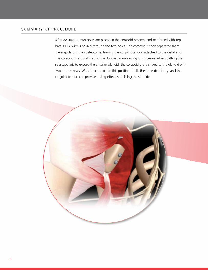
sUmmary of proCedUre
After evaluation, two holes are placed in the coracoid process, and reinforced with top
hats. chiA wire is passed through the two holes. the coracoid is then separated from
the scapula using an osteotome, leaving the conjoint tendon attached to the distal end.
the coracoid graft is affixed to the double cannula using long screws. After splitting the
subscapularis to expose the anterior glenoid, the coracoid graft is fixed to the glenoid with
two bone screws. With the coracoid in this position, it fills the bone deficiency, and the
conjoint tendon can provide a sling effect, stabilizing the shoulder.
5
THe depUy mITek laTarjeT InsTrUmenT porTfolIo
DePuy mitek provides a specialized set of instruments designed specifically for the Latarjet
procedure, whether performed arthroscopically or through the open technique. these
tools offer distinct advantages and benefits to the surgeon.
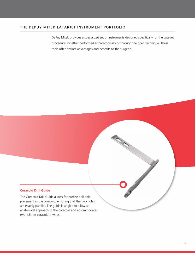
Coracoid Drill Guide
the coracoid Drill guide allows for precise drill hole placement in the coracoid, ensuring that the two holes are exactly parallel. the guide is angled to allow an anatomical approach to the coracoid and accommodates two 1.5mm coracoid k-wires.
6
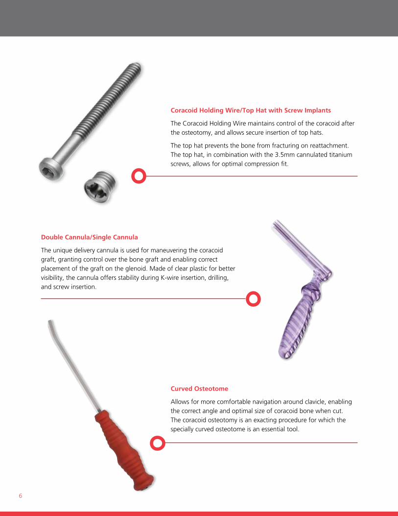
Curved Osteotome
Allows for more comfortable navigation around clavicle, enabling the correct angle and optimal size of coracoid bone when cut. the coracoid osteotomy is an exacting procedure for which the specially curved osteotome is an essential tool.
Double Cannula/Single Cannula
the unique delivery cannula is used for maneuvering the coracoid graft, granting control over the bone graft and enabling correct placement of the graft on the glenoid. made of clear plastic for better visibility, the cannula offers stability during k-wire insertion, drilling, and screw insertion.
Coracoid Holding Wire/Top Hat with Screw Implants
the coracoid holding Wire maintains control of the coracoid after the osteotomy, and allows secure insertion of top hats.
the top hat prevents the bone from fracturing on reattachment. the top hat, in combination with the 3.5mm cannulated titanium screws, allows for optimal compression fit.
7
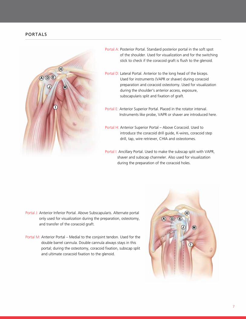
Portal j: Anterior inferior Portal. Above subscapularis. Alternate portal
only used for visualization during the preparation, osteotomy,
and transfer of the coracoid graft.
Portal m: Anterior Portal – medial to the conjoint tendon. used for the
double barrel cannula. Double cannula always stays in this
portal; during the osteotomy, coracoid fixation, subscap split
and ultimate coracoid fixation to the glenoid.
porTals
Portal A: Posterior Portal. standard posterior portal in the soft spot
of the shoulder. used for visualization and for the switching
stick to check if the coracoid graft is flush to the glenoid.
Portal D: Lateral Portal. Anterior to the long head of the biceps.
used for instruments (VAPr or shaver) during coracoid
preparation and coracoid osteotomy. used for visualization
during the shoulder’s anterior access, exposure,
subscapularis split and fixation of graft.
Portal e: Anterior superior Portal. Placed in the rotator interval.
instruments like probe, VAPr or shaver are introduced here.
Portal h: Anterior superior Portal – Above coracoid. used to
introduce the coracoid drill guide, k-wires, coracoid step
drill, tap, wire retriever, chiA and osteotomes.
Portal i: Ancillary Portal. used to make the subscap split with VAPr,
shaver and subscap channeler. Also used for visualization
during the preparation of the coracoid holes.
8
laTarjeT arTHrosCopIC sUrGICal TeCHnIQUe
Steps
1. joint evaluation and surgical final decision
2. shoulder’s elements access, exposure & preparation
3. split of subscapularis
4. Preparation of coracoid holes
5. coracoid osteotomy, mobilization & cannula fixation
6. coracoid transfer through subscapularis
7. coracoid glenoid fixation
PAtient Positioning: Prepare the patient in a standard manner for shoulder arthroscopy in a beach-chair position.
8
9
evalUaTIon of sHoUlder
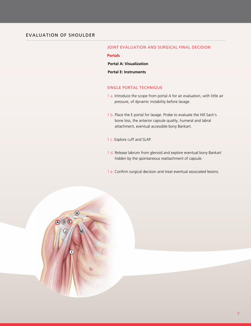
joInT evalUaTIon and sUrGICal fInal deCIsIon
Portals
Portal A: Visualization
Portal E: Instruments
sInGle porTal TeCHnIQUe
1 a. introduce the scope from portal A for air evaluation, with little air
pressure, of dynamic instability before lavage.
1 b. Place the e portal for lavage. Probe to evaluate the hill sach’s
bone loss, the anterior capsule quality, humeral and labral
attachment, eventual accessible bony Bankart.
1 c. explore cuff and sLAP.
1 d. release labrum from glenoid and explore eventual bony Bankart
hidden by the spontaneous reattachment of capsule.
1 e. confirm surgical decision and treat eventual associated lesions.
9
10
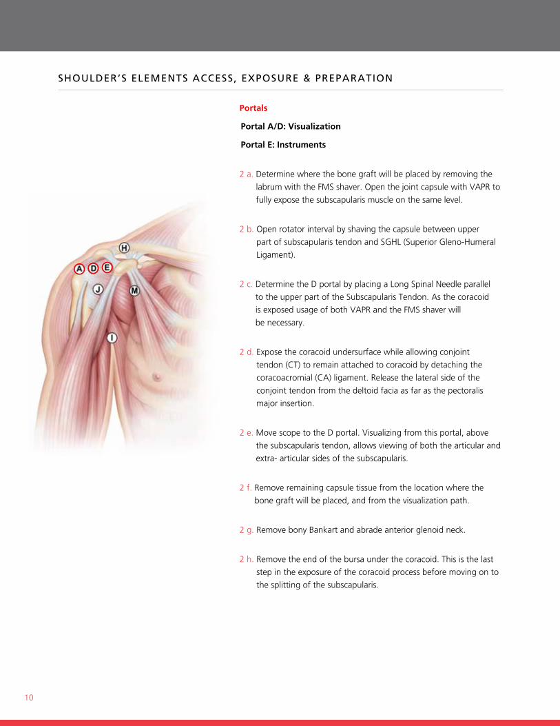
sHoUlder’s elemenTs aCCess, exposUre & preparaTIon
Portals
Portal A/D: Visualization
Portal E: Instruments
2 a. Determine where the bone graft will be placed by removing the
labrum with the fms shaver. open the joint capsule with VAPr to
fully expose the subscapularis muscle on the same level.
2 b. open rotator interval by shaving the capsule between upper
part of subscapularis tendon and sghL (superior gleno-humeral
Ligament).
2 c. Determine the D portal by placing a Long spinal needle parallel
to the upper part of the subscapularis tendon. As the coracoid
is exposed usage of both VAPr and the fms shaver will
be necessary.
2 d. expose the coracoid undersurface while allowing conjoint
tendon (ct) to remain attached to coracoid by detaching the
coracoacromial (cA) ligament. release the lateral side of the
conjoint tendon from the deltoid facia as far as the pectoralis
major insertion.
2 e. move scope to the D portal. Visualizing from this portal, above
the subscapularis tendon, allows viewing of both the articular and
extra- articular sides of the subscapularis.
2 f. remove remaining capsule tissue from the location where the
bone graft will be placed, and from the visualization path.
2 g. remove bony Bankart and abrade anterior glenoid neck.
2 h. remove the end of the bursa under the coracoid. this is the last
step in the exposure of the coracoid process before moving on to
the splitting of the subscapularis.
11
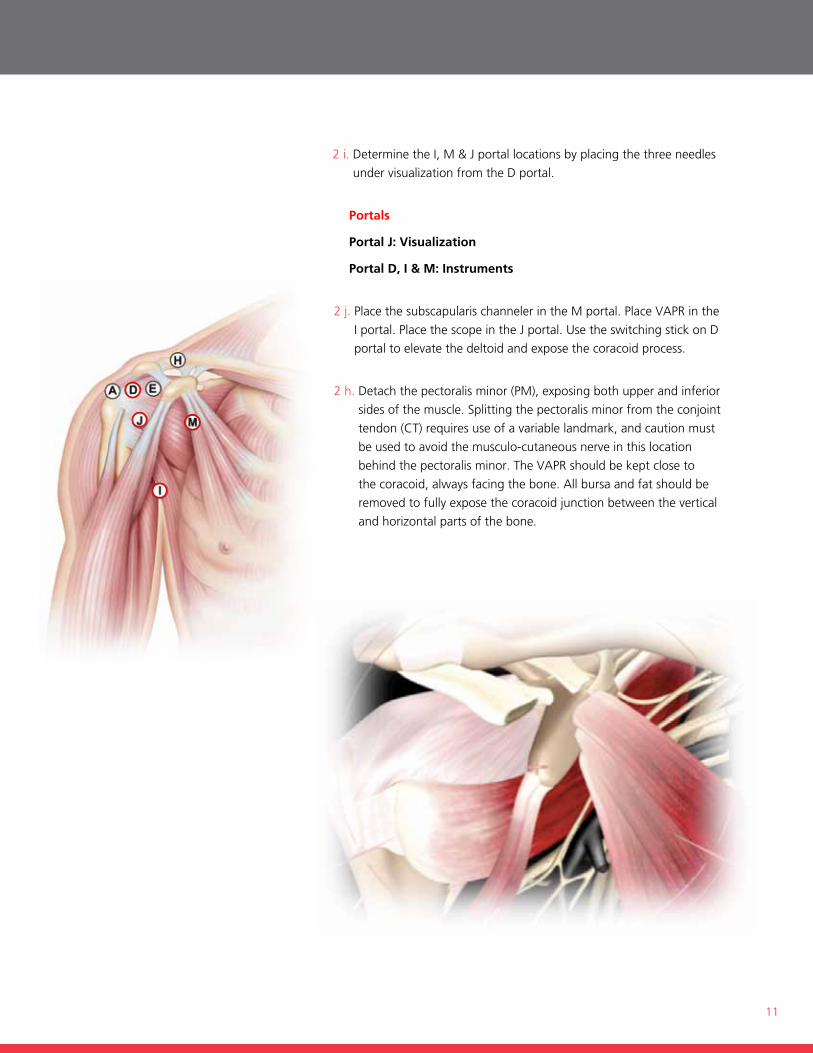
2 i. Determine the i, m & j portal locations by placing the three needles
under visualization from the D portal.
Portals
Portal J: Visualization
Portal D, I & M: Instruments
2 j. Place the subscapularis channeler in the m portal. Place VAPr in the
i portal. Place the scope in the j portal. use the switching stick on D
portal to elevate the deltoid and expose the coracoid process.
2 h. Detach the pectoralis minor (Pm), exposing both upper and inferior
sides of the muscle. splitting the pectoralis minor from the conjoint
tendon (ct) requires use of a variable landmark, and caution must
be used to avoid the musculo-cutaneous nerve in this location
behind the pectoralis minor. the VAPr should be kept close to
the coracoid, always facing the bone. All bursa and fat should be
removed to fully expose the coracoid junction between the vertical
and horizontal parts of the bone.
12
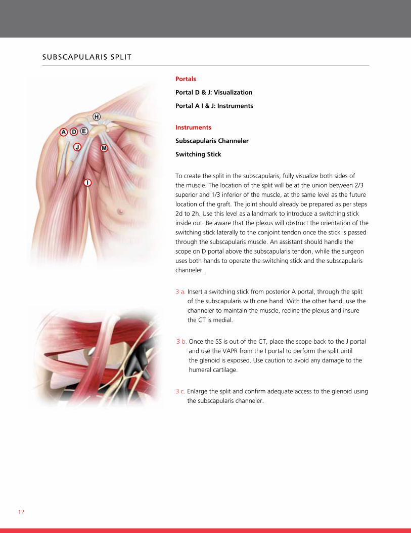
sUbsCapUlarIs splIT
Portals
Portal D & J: Visualization
Portal A I & J: Instruments
Instruments
Subscapularis Channeler
Switching Stick
to create the split in the subscapularis, fully visualize both sides of
the muscle. the location of the split will be at the union between 2/3
superior and 1/3 inferior of the muscle, at the same level as the future
location of the graft. the joint should already be prepared as per steps
2d to 2h. use this level as a landmark to introduce a switching stick
inside out. Be aware that the plexus will obstruct the orientation of the
switching stick laterally to the conjoint tendon once the stick is passed
through the subscapularis muscle. An assistant should handle the
scope on D portal above the subscapularis tendon, while the surgeon
uses both hands to operate the switching stick and the subscapularis
channeler.
3 a. insert a switching stick from posterior A portal, through the split
of the subscapularis with one hand. With the other hand, use the
channeler to maintain the muscle, recline the plexus and insure
the ct is medial.
3 b. once the ss is out of the ct, place the scope back to the j portal
and use the VAPr from the i portal to perform the split until
the glenoid is exposed. use caution to avoid any damage to the
humeral cartilage.
3 c. enlarge the split and confirm adequate access to the glenoid using
the subscapularis channeler.
13
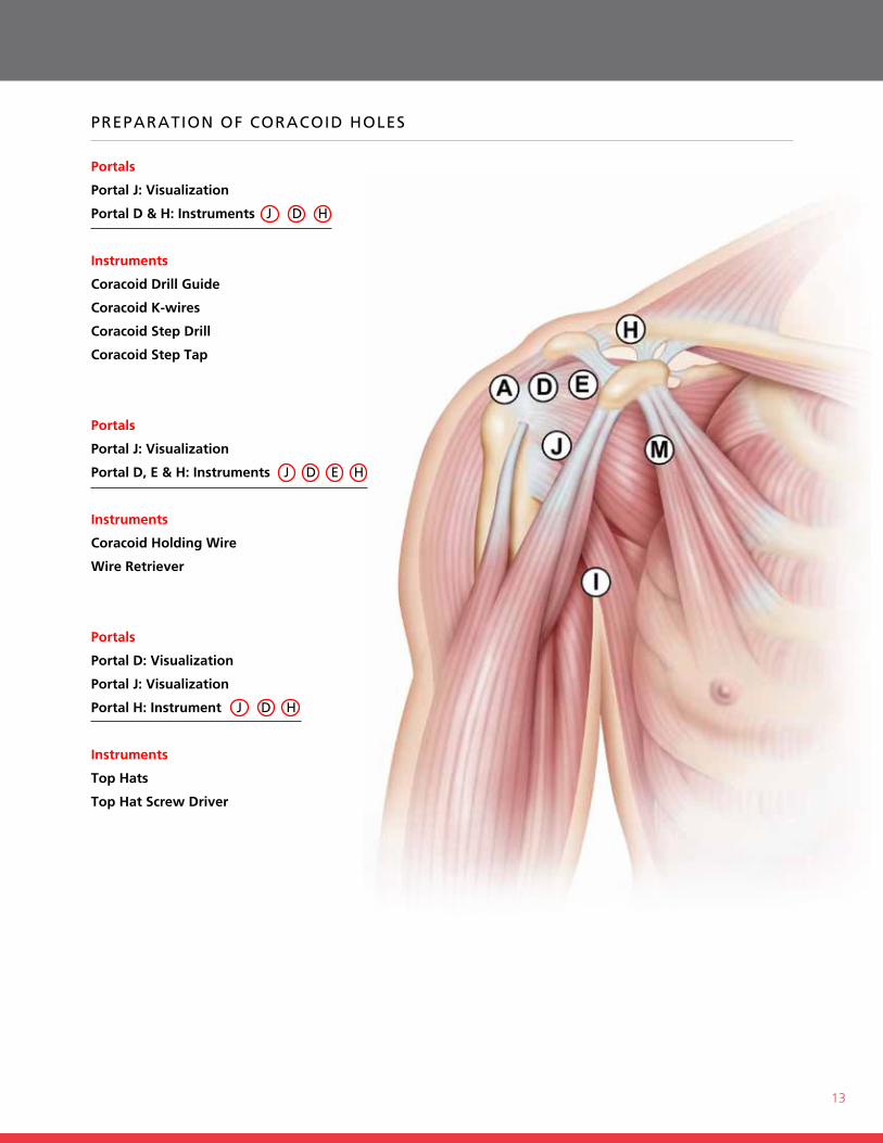
preparaTIon of CoraCoId Holes
Portals
Portal J: Visualization
Portal D & H: Instruments j d H
Instruments
Coracoid Drill Guide
Coracoid K-wires
Coracoid Step Drill
Coracoid Step Tap
Portals
Portal J: Visualization
Portal D, E & H: Instruments j d e H
Instruments
Coracoid Holding Wire
Wire Retriever
Portals
Portal D: Visualization
Portal J: Visualization
Portal H: Instrument j d H
Instruments
Top Hats
Top Hat Screw Driver

15
4 i. remove the coracoid step Drill from the alpha hole and remove
the k-wire.
4 j. Drill the beta hole completely through the coracoid, over the
coracoid k-wire in the same manner.
4 k. introduce the coracoid holding Wire (chiA) through the coracoid
step tap. thread the coracoid step tap through the alpha hole first,
and then the beta hole. Leave the step tap in the beta hole.
4 l. Push the coracoid holding Wire (chiA) through the coracoid step
tap into the beta hole. ensure that the kite loop is threaded first, and
totally protrudes through the coracoid.
4 m. Pass a suture manipulator grasper through the e portal and grasp
the coracoid holding Wire (chiA). remove the coracoid step tap,
leaving the coracoid holding Wire (chiA) inside the beta hole.
4 n. use the suture manipulator grasper to lead the coracoid holding
Wire (chiA) toward the alpha hole. retrieve the kite loop and pull it
out using the Wire retriever .
4 o. cut the loop of the chiA and place a clamp on the end of the wire
exiting from the beta hole. Put top hats in the alpha and beta holes.
4 p. Put the alpha end of the coracoid holding Wire in the top hat from
portal h.
4 q. screw in the top hat using the top hat screw Driver.
4 r. switch the clamp to the alpha end of the wire. Put the beta end of
the wire in the top hat from portal h. screw in the top hat using the
top hat screw Driver.
16
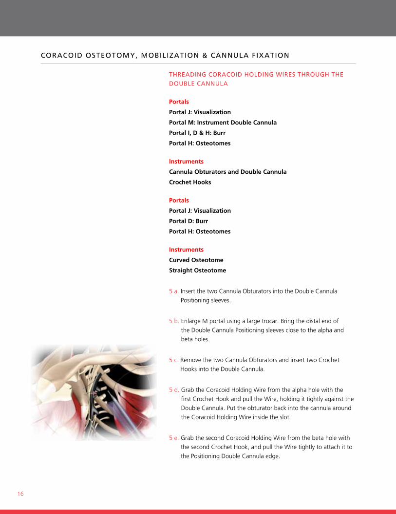
CoraCoId osTeoTomy, mobIlIzaTIon & CannUla fIxaTIon
THreadInG CoraCoId HoldInG WIres THroUGH THe doUble CannUla
Portals
Portal J: Visualization
Portal M: Instrument Double Cannula
Portal I, D & H: Burr
Portal H: Osteotomes
Instruments
Cannula Obturators and Double Cannula
Crochet Hooks
Portals
Portal J: Visualization
Portal D: Burr
Portal H: Osteotomes
Instruments
Curved Osteotome
Straight Osteotome
5 a. insert the two cannula obturators into the Double cannula
Positioning sleeves.
5 b. enlarge m portal using a large trocar. Bring the distal end of
the Double cannula Positioning sleeves close to the alpha and
beta holes.
5 c. remove the two cannula obturators and insert two crochet
hooks into the Double cannula.
5 d. grab the coracoid holding Wire from the alpha hole with the
first crochet hook and pull the Wire, holding it tightly against the
Double cannula. Put the obturator back into the cannula around
the coracoid holding Wire inside the slot.
5 e. grab the second coracoid holding Wire from the beta hole with
the second crochet hook, and pull the Wire tightly to attach it to
the Positioning Double cannula edge.
17
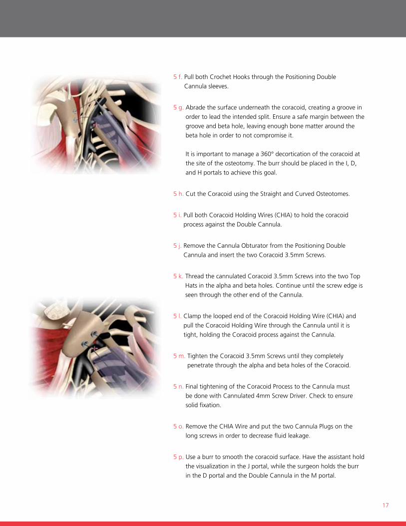
5 f. Pull both crochet hooks through the Positioning Double
cannula sleeves.
5 g. Abrade the surface underneath the coracoid, creating a groove in
order to lead the intended split. ensure a safe margin between the
groove and beta hole, leaving enough bone matter around the
beta hole in order to not compromise it.
it is important to manage a 360° decortication of the coracoid at
the site of the osteotomy. the burr should be placed in the i, D,
and h portals to achieve this goal.
5 h. cut the coracoid using the straight and curved osteotomes.
5 i. Pull both coracoid holding Wires (chiA) to hold the coracoid
process against the Double cannula.
5 j. remove the cannula obturator from the Positioning Double
cannula and insert the two coracoid 3.5mm screws.
5 k. thread the cannulated coracoid 3.5mm screws into the two top
hats in the alpha and beta holes. continue until the screw edge is
seen through the other end of the cannula.
5 l. clamp the looped end of the coracoid holding Wire (chiA) and
pull the coracoid holding Wire through the cannula until it is
tight, holding the coracoid process against the cannula.
5 m. tighten the coracoid 3.5mm screws until they completely
penetrate through the alpha and beta holes of the coracoid.
5 n. final tightening of the coracoid Process to the cannula must
be done with cannulated 4mm screw Driver. check to ensure
solid fixation.
5 o. remove the chiA Wire and put the two cannula Plugs on the
long screws in order to decrease fluid leakage.
5 p. use a burr to smooth the coracoid surface. have the assistant hold
the visualization in the j portal, while the surgeon holds the burr
in the D portal and the Double cannula in the m portal.
18
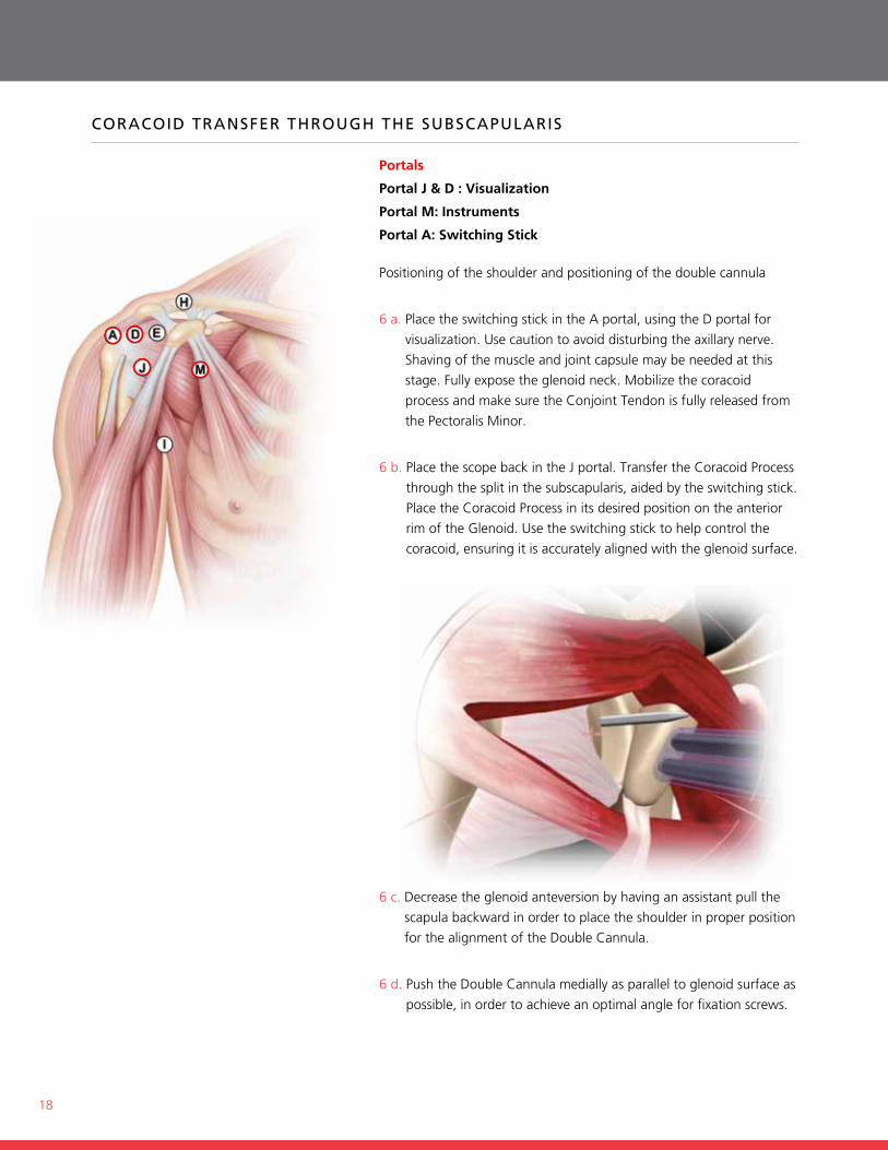
CoraCoId Transfer THroUGH THe sUbsCapUlarIs
Portals
Portal J & D : Visualization
Portal M: Instruments
Portal A: Switching Stick
Positioning of the shoulder and positioning of the double cannula
6 a. Place the switching stick in the A portal, using the D portal for
visualization. use caution to avoid disturbing the axillary nerve.
shaving of the muscle and joint capsule may be needed at this
stage. fully expose the glenoid neck. mobilize the coracoid
process and make sure the conjoint tendon is fully released from
the Pectoralis minor.
6 b. Place the scope back in the j portal. transfer the coracoid Process
through the split in the subscapularis, aided by the switching stick.
Place the coracoid Process in its desired position on the anterior
rim of the glenoid. use the switching stick to help control the
coracoid, ensuring it is accurately aligned with the glenoid surface.
6 c. Decrease the glenoid anteversion by having an assistant pull the
scapula backward in order to place the shoulder in proper position
for the alignment of the Double cannula.
6 d. Push the Double cannula medially as parallel to glenoid surface as
possible, in order to achieve an optimal angle for fixation screws.
19
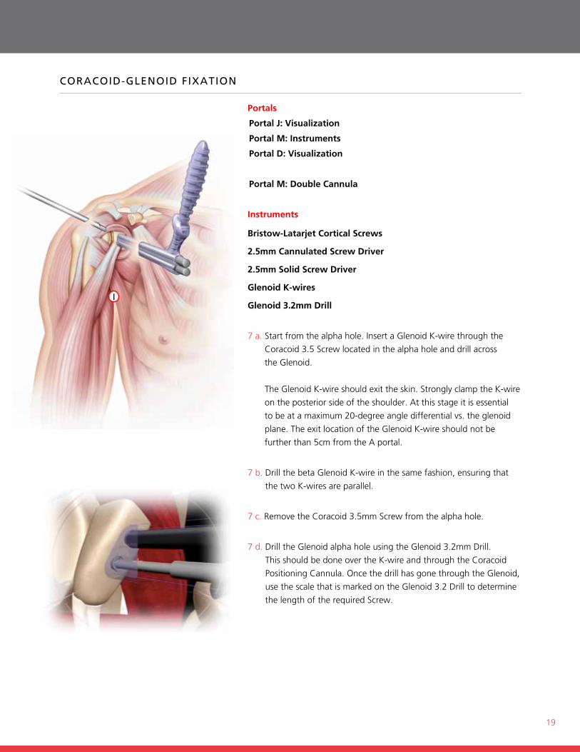
CoraCoId-GlenoId fIxaTIon
Portals
Portal J: Visualization
Portal M: Instruments
Portal D: Visualization
Portal M: Double Cannula
Instruments
Bristow-Latarjet Cortical Screws
2.5mm Cannulated Screw Driver
2.5mm Solid Screw Driver
Glenoid K-wires
Glenoid 3.2mm Drill
7 a. start from the alpha hole. insert a glenoid k-wire through the
coracoid 3.5 screw located in the alpha hole and drill across
the glenoid.
the glenoid k-wire should exit the skin. strongly clamp the k-wire
on the posterior side of the shoulder. At this stage it is essential
to be at a maximum 20-degree angle differential vs. the glenoid
plane. the exit location of the glenoid k-wire should not be
further than 5cm from the A portal.
7 b. Drill the beta glenoid k-wire in the same fashion, ensuring that
the two k-wires are parallel.
7 c. remove the coracoid 3.5mm screw from the alpha hole.
7 d. Drill the glenoid alpha hole using the glenoid 3.2mm Drill.
this should be done over the k-wire and through the coracoid
Positioning cannula. once the drill has gone through the glenoid,
use the scale that is marked on the glenoid 3.2 Drill to determine
the length of the required screw.
I
20
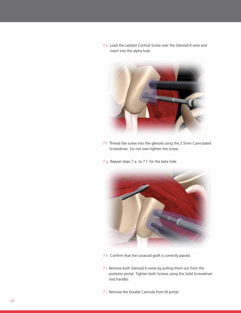
7 e. Load the Latarjet cortical screw over the glenoid k-wire and
insert into the alpha hole.
7 f. thread the screw into the glenoid using the 2.5mm cannulated
screwdriver. Do not over-tighten the screw.
7 g. repeat steps 7 a. to 7 f. for the beta hole.
7 h. confirm that the coracoid graft is correctly placed.
7 i. remove both glenoid k-wires by pulling them out from the
posterior portal. tighten both screws using the solid screwdriver
(red handle).
7 j. remove the Double cannula from m portal.
21
laTarjeT open sUrGICal TeCHnIQUe
STEPS
1. exposure
2. Preparation of coracoid holes
3. cutting the coracoid
4. fixing the Double cannula to the coracoid, and exposure of both
sides of the subscapularis
5. coracoid transfer through the subscapularis
6. coracoid-glenoid fixation
op
en su
rgical Tech
niq
ue
22
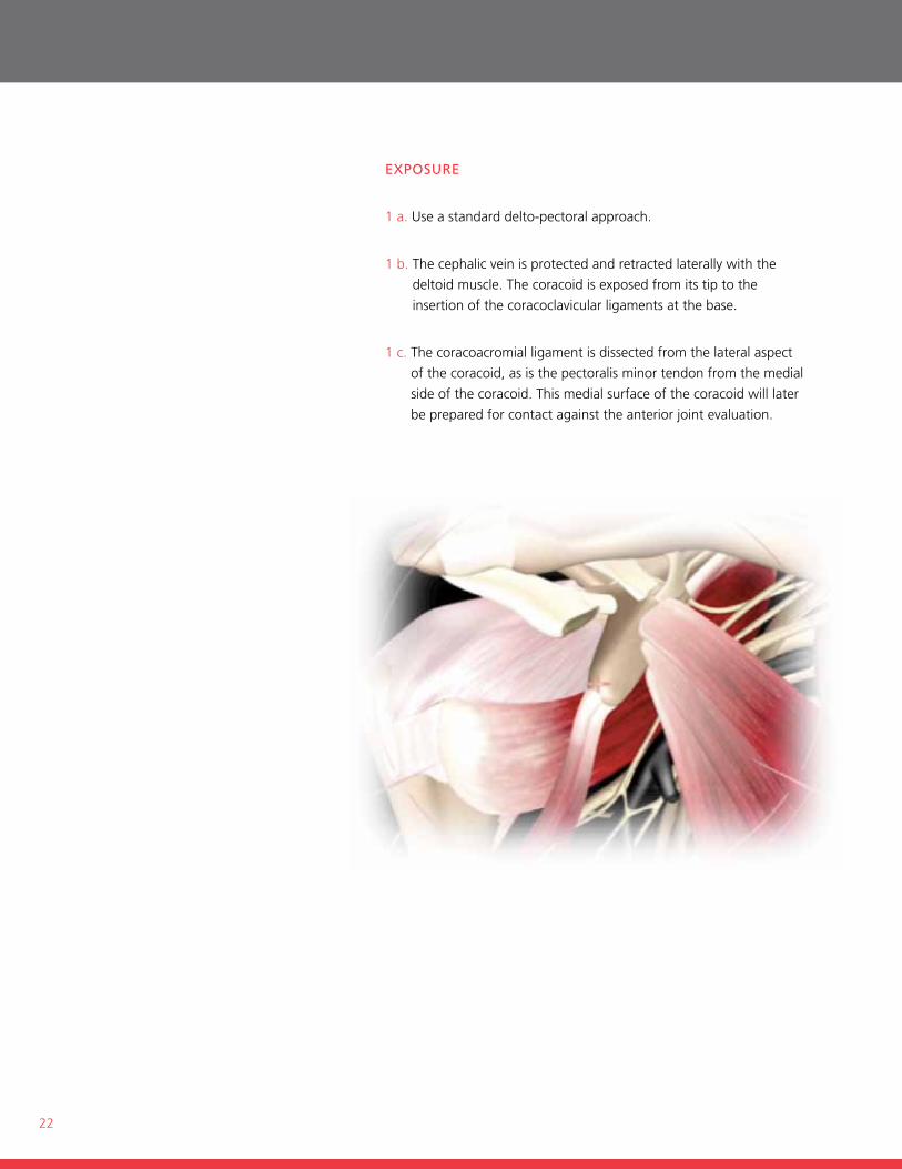
exposUre
1 a. use a standard delto-pectoral approach.
1 b. the cephalic vein is protected and retracted laterally with the
deltoid muscle. the coracoid is exposed from its tip to the
insertion of the coracoclavicular ligaments at the base.
1 c. the coracoacromial ligament is dissected from the lateral aspect
of the coracoid, as is the pectoralis minor tendon from the medial
side of the coracoid. this medial surface of the coracoid will later
be prepared for contact against the anterior joint evaluation.
23
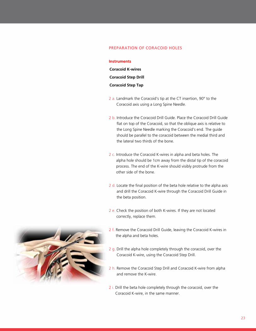
preparaTIon of CoraCoId Holes
Instruments
Coracoid K-wires
Coracoid Step Drill
Coracoid Step Tap
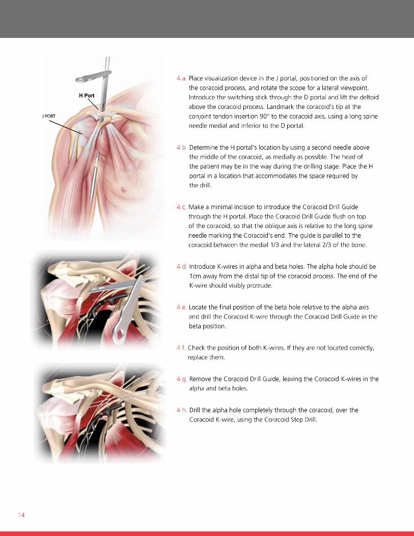
2 a. Landmark the coracoid’s tip at the ct insertion, 90° to the
coracoid axis using a Long spine needle.
2 b. introduce the coracoid Drill guide. Place the coracoid Drill guide
flat on top of the coracoid, so that the oblique axis is relative to
the Long spine needle marking the coracoid’s end. the guide
should be parallel to the coracoid between the medial third and
the lateral two thirds of the bone.
2 c. introduce the coracoid k-wires in alpha and beta holes. the
alpha hole should be 1cm away from the distal tip of the coracoid
process. the end of the k-wire should visibly protrude from the
other side of the bone.
2 d. Locate the final position of the beta hole relative to the alpha axis
and drill the coracoid k-wire through the coracoid Drill guide in
the beta position.
2 e. check the position of both k-wires. if they are not located
correctly, replace them.
2 f. remove the coracoid Drill guide, leaving the coracoid k-wires in
the alpha and beta holes.
2 g. Drill the alpha hole completely through the coracoid, over the
coracoid k-wire, using the coracoid step Drill.
2 h. remove the coracoid step Drill and coracoid k-wire from alpha
and remove the k-wire.
2 i. Drill the beta hole completely through the coracoid, over the
coracoid k-wire, in the same manner.
24
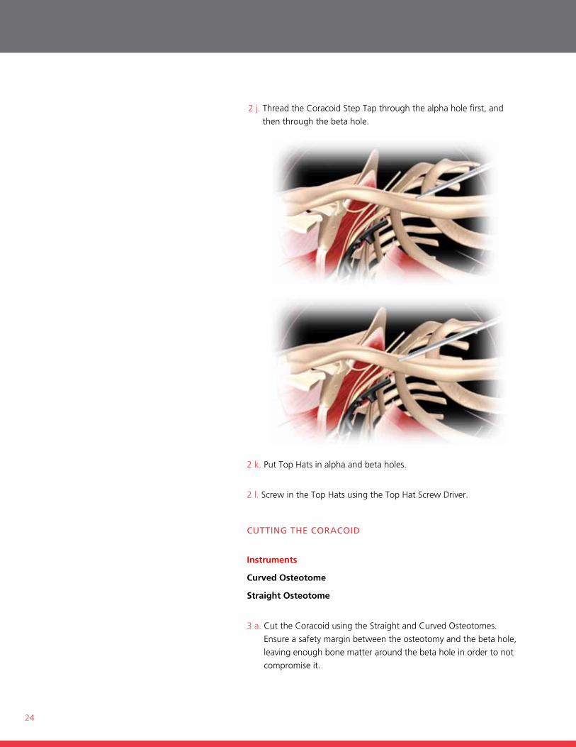
2 j. thread the coracoid step tap through the alpha hole first, and
then through the beta hole.
2 k. Put top hats in alpha and beta holes.
2 l. screw in the top hats using the top hat screw Driver.
CUTTInG THe CoraCoId
Instruments
Curved Osteotome
Straight Osteotome
3 a. cut the coracoid using the straight and curved osteotomes.
ensure a safety margin between the osteotomy and the beta hole,
leaving enough bone matter around the beta hole in order to not
compromise it.
25
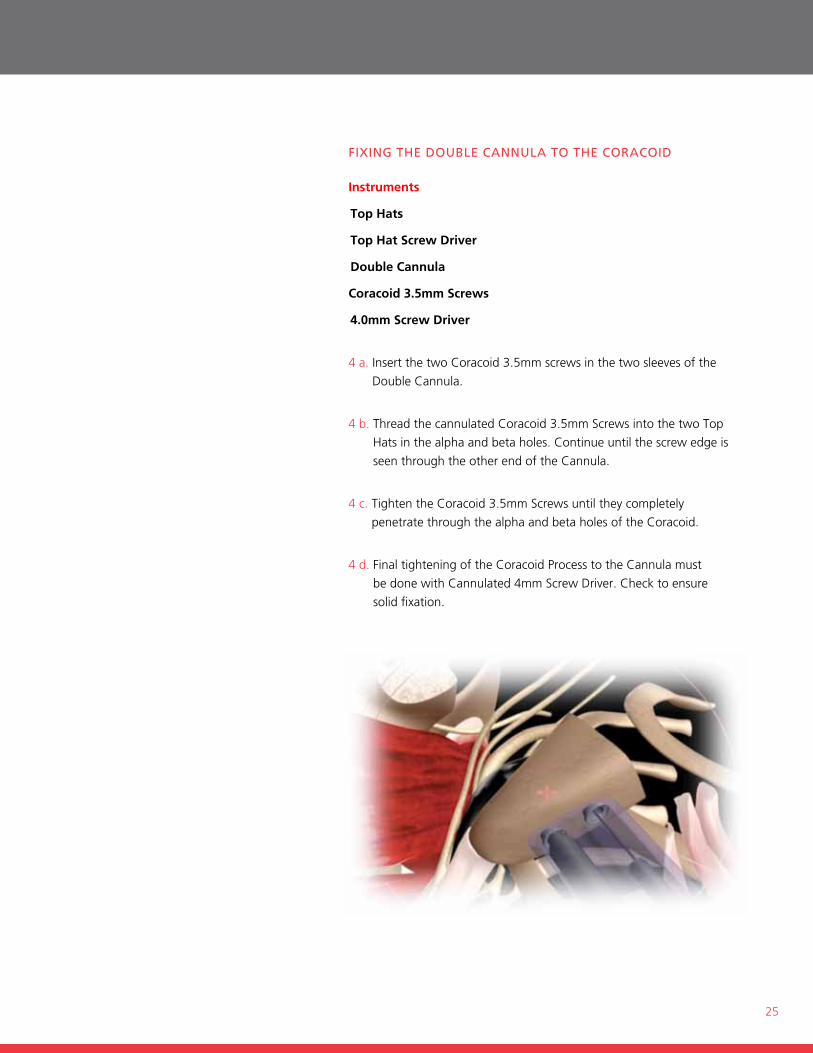
fIxInG THe doUble CannUla To THe CoraCoId
Instruments
Top Hats
Top Hat Screw Driver
Double Cannula
Coracoid 3.5mm Screws
4.0mm Screw Driver
4 a. insert the two coracoid 3.5mm screws in the two sleeves of the
Double cannula.
4 b. thread the cannulated coracoid 3.5mm screws into the two top
hats in the alpha and beta holes. continue until the screw edge is
seen through the other end of the cannula.
4 c. tighten the coracoid 3.5mm screws until they completely
penetrate through the alpha and beta holes of the coracoid.
4 d. final tightening of the coracoid Process to the cannula must
be done with cannulated 4mm screw Driver. check to ensure
solid fixation.
26
CoraCoId Transfer THroUGH THe sUbsCapUlarIs
Positioning of the shoulder and positioning of the double cannula
5 a. fully expose the glenoid neck. mobilize the coracoid process
and make sure the conjoint tendon is fully released from the
pectoralis minor.
5 b. transfer the coracoid Process through the split of
the subscapularis.
Place the coracoid Process in its desired position on the anterior
rim of the glenoid. the coracoid should be flat on the glenoid
surface.
5 c. the assistant should pull the scapula backward in order to
decrease the glenoid anteversion.
5 d. Push the Double cannula medially as parallel to glenoid surface as
possible, in order to achieve an optimal angle for fixation screws.
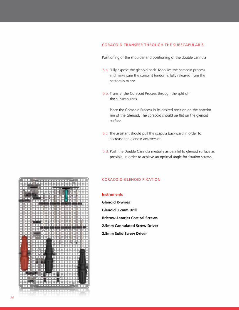
CoraCoId-GlenoId fIxaTIon
Instruments
Glenoid K-wires
Glenoid 3.2mm Drill
Bristow-Latarjet Cortical Screws
2.5mm Cannulated Screw Driver
2.5mm Solid Screw Driver
27
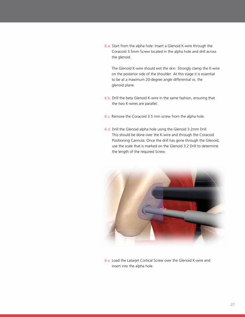
6 a. start from the alpha hole: insert a glenoid k-wire through the
coracoid 3.5mm screw located in the alpha hole and drill across
the glenoid.
the glenoid k-wire should exit the skin. strongly clamp the k-wire
on the posterior side of the shoulder. At this stage it is essential
to be at a maximum 20-degree angle differential vs. the
glenoid plane.
6 b. Drill the beta glenoid k-wire in the same fashion, ensuring that
the two k-wires are parallel.
6 c. remove the coracoid 3.5 mm screw from the alpha hole.
6 d. Drill the glenoid alpha hole using the glenoid 3.2mm Drill.
this should be done over the k-wire and through the coracoid
Positioning cannula. once the drill has gone through the glenoid,
use the scale that is marked on the glenoid 3.2 Drill to determine
the length of the required screw.
6 e. Load the Latarjet cortical screw over the glenoid k-wire and
insert into the alpha hole.
28
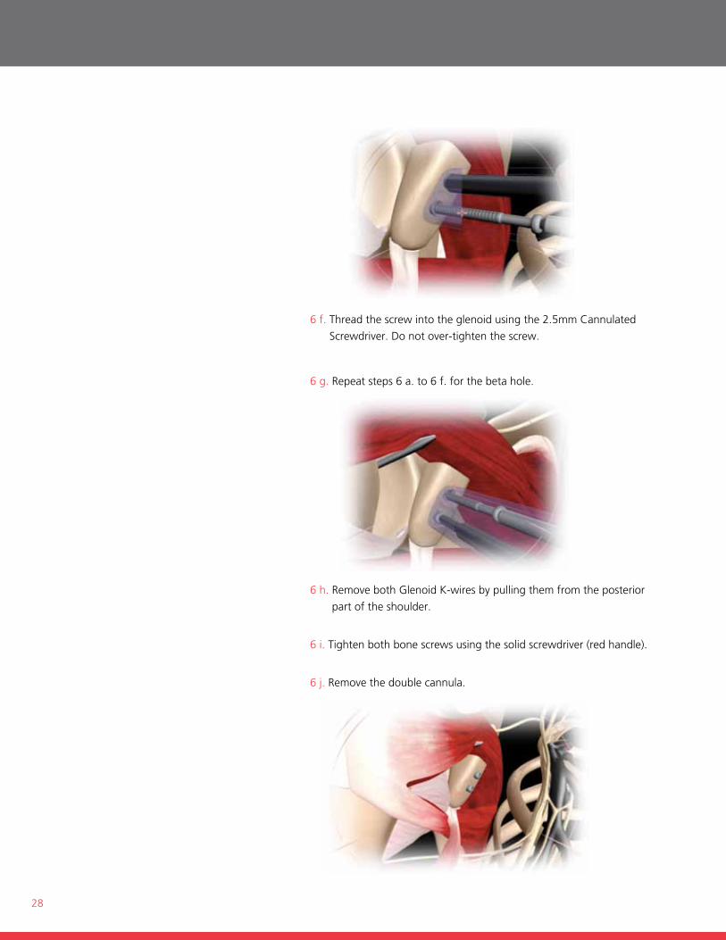
6 f. thread the screw into the glenoid using the 2.5mm cannulated
screwdriver. Do not over-tighten the screw.
6 g. repeat steps 6 a. to 6 f. for the beta hole.
6 h. remove both glenoid k-wires by pulling them from the posterior
part of the shoulder.
6 i. tighten both bone screws using the solid screwdriver (red handle).
6 j. remove the double cannula.
29
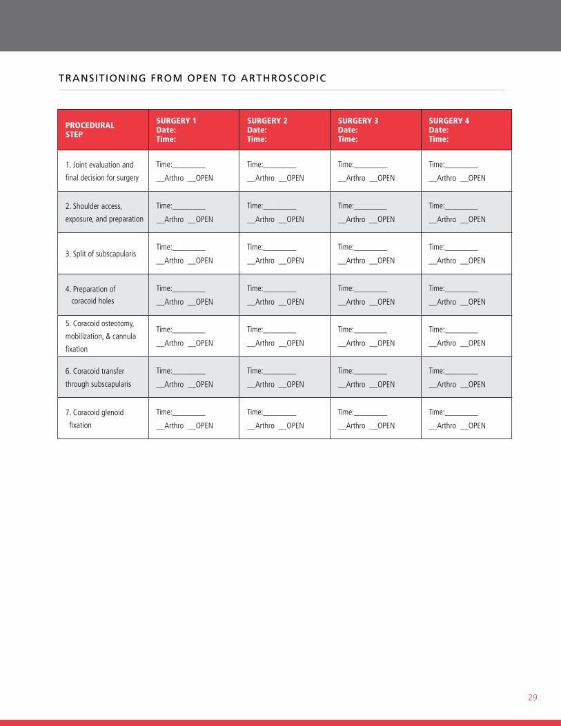
TransITIonInG from open To arTHrosCopIC
PROCEDURAL STEP
SURGERY 1 Date: Time:
SURGERY 2 Date: Time:
SURGERY 3 Date: Time:
SURGERY 4 Date: Time:
1. Joint evaluation and
final decision for surgery
Time:________
__Arthro __OPEN
Time:________
__Arthro __OPEN
Time:________
__Arthro __OPEN
Time:________
__Arthro __OPEN
2. Shoulder access,
exposure, and preparation
Time:________
__Arthro __OPEN
Time:________
__Arthro __OPEN
Time:________
__Arthro __OPEN
Time:________
__Arthro __OPEN
3. Split of subscapularisTime:________
__Arthro __OPEN
Time:________
__Arthro __OPEN
Time:________
__Arthro __OPEN
Time:________
__Arthro __OPEN
4. Preparation of coracoid holes
Time:________
__Arthro __OPEN
Time:________
__Arthro __OPEN
Time:________
__Arthro __OPEN
Time:________
__Arthro __OPEN
5. Coracoid osteotomy,
mobilization, & cannula
fixation
Time:________
__Arthro __OPEN
Time:________
__Arthro __OPEN
Time:________
__Arthro __OPEN
Time:________
__Arthro __OPEN
6. Coracoid transfer
through subscapularis
Time:________
__Arthro __OPEN
Time:________
__Arthro __OPEN
Time:________
__Arthro __OPEN
Time:________
__Arthro __OPEN
7. Coracoid glenoid
fixation
Time:________
__Arthro __OPEN
Time:________
__Arthro __OPEN
Time:________
__Arthro __OPEN
Time:________
__Arthro __OPEN
www.depuy.com
©DePuy mitek, inc. 2011. All rights reserved.
P/n 901134 3/11 ADDB/LP
DePuy Mitek, Inc.325 Paramount Driveraynham, mA 02767usAtel: +1 (800) 382-4682
DePuy Mitek EMEA, a division ofJohnson & Johnson Medical SpaVia del mare, 5600040 Practica di mare, rome, italytel: +39 906 9119 41fax: +39 906 9119 4090