Embed Size (px)
Citation preview
External Hex
Surgical ManualPreservation By Design®
Instructions For Use:For a detailed explanation of the osteotomy preparation and implant placement guidelines, refer to the appropriate Surgical Manual(s).
Description: BIOMET 3i Dental Implants are manufactured from biocompatible titanium or titanium alloy. BIOMET 3i Dental Implants include various surface treatments. For specific product descriptions, please refer to individual product labels.
Indications For Use: BIOMET 3i Dental Implants are intended for surgical placement in the upper or lower jaw to provide a means for prosthetic attachment in single tooth restorations and in partially or fully edentulous spans with multiple single teeth, or as a terminal or intermediary abutment for fixed or removable bridgework, and to retain overdentures.
BIOMET 3i NanoTite™ and OSSEOTITE® Dental Implants are intended for immediate function on single tooth and/or multiple tooth applications when good primary stability is achieved, with appropriate occlusal loading, in order to restore chewing function.
Contraindications: Placement of dental implants may be precluded by both patient conditions that are contraindications for surgery as well as hypersensitivity to commercially pure titanium or titanium alloy (including vanadium, aluminum, and calcium phosphate).
BIOMET 3i Dental Implants should not be placed in patients where the remaining jaw bone is too diminished to provide adequate implant stability.
Warnings: Excessive bone loss or breakage of a dental implant may occur when an implant is loaded beyond its functional capability. Physiological and anatomical conditions may affect the performance of dental implants.
Mishandling of small components inside the patient’s mouth carries a risk of aspiration and/or swallowing.
Forcing the implant into the osteotomy deeper than the depth established by the drills can result in damage to the implant, driver, or osteotomy.
For short implants, clinicians should closely monitor patients for any of the following conditions: peri-implant bone loss, changes to the implant’s response to percussion or radiographic changes in bone-to-implant contact along the implant’s length. If the implant shows mobility or greater than 50% bone loss, the implant should be evaluated for possible removal. If a clinician chooses a short implant, then the clinician should consider a two-stage surgical approach, splinting a short implant to an additional implant, and placement of the widest possible fixture. In addition, if a clinician chooses a short implant, then the clinician should allow longer periods for osseointegration and avoid immediate loading.
Reuse of BIOMET 3i Products that are labeled for single-use may result in product contamination, patient infection and/or failure of the device to perform as intended.
MRI Statement: BIOMET 3i Dental Implants have not been evaluated for safety, heating, migration, or compatibility in the Magnetic Resonance Imaging (MRI) environment.
Precautions: These devices are only to be used by trained professionals. The surgical and restorative techniques required to properly utilize these devices are highly specialized and complex procedures. Improper technique can lead to implant failure, loss of supporting bone, restoration fracture, screw loosening and aspiration. When the clinician has determined adequate primary stability is achieved, immediate functional loading can be considered.
The following should be taken into consideration when placing dental implants: bone quality, oral hygiene, and medical conditions such as blood disorders or uncontrolled hormonal conditions. The healing period varies depending on the quality of the bone at the implantation site, the tissue response to the implanted device and the surgeon’s evaluation of the patient’s bone density at the time of the surgical procedure. Proper occlusion should be evaluated on the implant restoration to avoid excessive force during the healing period on the implant.
It is recommended that implants less than 4mm diameter NOT be placed in the posterior regions.
Sterility: All dental implants are supplied sterile and are labeled “STERILE”. All products sold sterile are for single-use before the expiration date printed on the product label. Do not use sterile products if the packaging has been damaged or previously opened. Do not re-sterilize.
Storage and Handling: Devices should be stored at room temperature. Refer to individual product labels and this Surgical Manual for special storage or handling conditions.
Potential Adverse Events: Potential adverse events associated with the use of dental implants may include: failure to integrate, loss of integration, dehiscence requiring bone grafting, perforation of the maxillary sinus, inferior border, lingual plate, labial plate, inferior alveolar canal or gingiva, infection as reported by abscess, fistula, suppuration, inflammation, or radiolucency, persistent pain, numbness, paresthesia, hyperplasia, excessive bone loss requiring intervention, implant breakage or fracture, systemic infection, nerve injury, and aspiration.
Caution: U.S. Federal Law restricts this device to sale by or on the order of a licensed dentist or physician.
Important Product Information
This document applies to Dental Implants.
Table Of Contents
Introduction And Treatment Planning . . . . . . . . . . . . . . . . . . . . . . . . . . . . . . . . . . . . . . . . . . 1Preoperative Planning . . . . . . . . . . . . . . . . . . . . . . . . . . . . . . . . . . . . . . . . . . . . . . . . . . . . . . 2Top-Down Treatment Planning . . . . . . . . . . . . . . . . . . . . . . . . . . . . . . . . . . . . . . . . . . . . . 3-4Surgical Precautions . . . . . . . . . . . . . . . . . . . . . . . . . . . . . . . . . . . . . . . . . . . . . . . . . . . . . . . . 5Cleaning And Sterilization . . . . . . . . . . . . . . . . . . . . . . . . . . . . . . . . . . . . . . . . . . . . . . . . . . . 6Bone Density . . . . . . . . . . . . . . . . . . . . . . . . . . . . . . . . . . . . . . . . . . . . . . . . . . . . . . . . . . . . 7
3i T3® External Hex Tapered ImplantsWhy Tapered Implants Are Different . . . . . . . . . . . . . . . . . . . . . . . . . . . . . . . . 9Quad Shaping Drills (QSDs) . . . . . . . . . . . . . . . . . . . . . . . . . . . . . . . . . . . . . . . . . . . . . . . . 10Twist Drill Depth Marking System . . . . . . . . . . . . . . . . . . . . . . . . . . . . . . . . . . . . . . . . . 11-14Implant Depth/Direction Indicator (NTDI) . . . . . . . . . . . . . . . . . . . . . . . . . . . . . . . . . . . . . . 15Implant Bone Taps And Bone Tap Kit (NTAPK) . . . . . . . . . . . . . . . . . . . . . . . . . . . . . . . . . . 16Implant Surgical Tray (QNTSK) . . . . . . . . . . . . . . . . . . . . . . . . . . . . . . . . . . . . . . . . . . . . . . 17Quick Reference Subcrestal Surgical Protocol . . . . . . . . . . . . . . . . . . . . . . . . . . . . . . . . . 18-19Subcrestal Surgical Protocol 3i T3 External Hex Tapered 3.25mm(D) Implants . . . . . . . . . . . . . . . . . . . . . . . . . . . 20-22 3i T3 External Hex Tapered 4mm(D) Implants . . . . . . . . . . . . . . . . . . . . . . . . . . . . . . 23-25 3i T3 External Hex Tapered 5mm(D) Implants . . . . . . . . . . . . . . . . . . . . . . . . . . . . . . 26-28 3i T3 External Hex Tapered 6mm(D) Implants . . . . . . . . . . . . . . . . . . . . . . . . . . . . . . 29-32Subcrestal Implant Placement Protocol . . . . . . . . . . . . . . . . . . . . . . . . . . . . . . . . . . . . . 33-35
3i T3 External Hex Parallel Walled ImplantsTwist Drill Depth Marking System . . . . . . . . . . . . . . . . . . . . . . . . . . . . . . . . . . . . . . . . . 37-40Quick Reference Subcrestal Surgical Protocol . . . . . . . . . . . . . . . . . . . . . . . . . . . . . . . . . 41-43Subcrestal Surgical Protocol 3i T3 External Hex Parallel Walled 3.25mm(D) Implants. . . . . . . . . . . . . . . . . . . . . . . 44-45 3i T3 External Hex Parallel Walled 3.75mm(D) Implants. . . . . . . . . . . . . . . . . . . . . . . 46-47 3i T3 External Hex Parallel Walled 4mm(D) Implants . . . . . . . . . . . . . . . . . . . . . . . . . 48-49 3i T3 External Hex Parallel Walled 5mm(D) Implants . . . . . . . . . . . . . . . . . . . . . . . . . 50-51 3i T3 External Hex Parallel Walled 6mm(D) Implants . . . . . . . . . . . . . . . . . . . . . . . . . 52-54Subcrestal Implant Placement Protocol . . . . . . . . . . . . . . . . . . . . . . . . . . . . . . . . . . . . . 55-57
3i T3 External Hex Tapered & Parallel Walled ImplantsSurgical Indexing . . . . . . . . . . . . . . . . . . . . . . . . . . . . . . . . . . . . . . . . . . . . . . . . . . . . . . 58-59Single Stage Treatment Protocol . . . . . . . . . . . . . . . . . . . . . . . . . . . . . . . . . . . . . . . . . . . . . 60Implant Placement In Dense Bone . . . . . . . . . . . . . . . . . . . . . . . . . . . . . . . . . . . . . . . . . 61-62Bone Profiling . . . . . . . . . . . . . . . . . . . . . . . . . . . . . . . . . . . . . . . . . . . . . . . . . . . . . . . . . . . 63
1
Introduction And Treatment Planning
These instructions were designed to serve as a reference guide for dental practitioners utilizing Implants and Surgical Instruments. The design of BIOMET 3i Implants and Surgical Instruments enable the practitioner to place implants in edentulous or partially edentulous mandibles or maxillae in order to support fixed and removable bridgework or single tooth crowns and overdentures.
General Information:The success of any dental implant system depends upon proper use of the components and instrumentation. This manual is not intended for use as a substitute for professional training and experience.
Treatment Planning:Patient Evaluation And SelectionSeveral important factors must be considered when evaluating a patient prior to implant surgery. The presurgical evaluation must include a cautious and detailed assessment of the patient’s general health, current medical status, medical history, oral hygiene, motivation and expectations. Factors such as heavy tobacco use, masticatory function and alcohol consumption should also be considered. In addition, the clinician should determine if the case presents an acceptable anatomical basis conducive to implant placement. An extensive intraoral examination should be undertaken to evaluate the oral cavity for any potential bone or soft-tissue pathology. The examiner should also determine the periodontal status of the
remaining teeth, the health of the soft-tissue and the presence of occlusal abnormalities such as bruxism or crossbite. The presence of other conditions that could adversely affect any existing natural dentition or healthy soft-tissue surrounding the implant should also be evaluated.
Diseases of the mucous membrane and connective tissues, pathologic bone disease and severe malocclusion could affect the determination of whether a patient is a suitable implant candidate.
The use of anticoagulants and the existence of metabolic diseases, such as diabetes, allergies, chronic renal or cardiac disease and blood dyscrasia could significantly influence the patient’s ability to successfully undergo implant procedures.
If the patient’s medical history reveals an existing condition or signals a potential problem that may compromise treatment and/or the patient’s well-being, consultation with a physician is recommended.
2
Preoperative Planning
Preoperative Planning:Proper treatment planning, as well as the selection of the proper implant length and diameter, are crucial to the long-term success of the implant and restoration. Before an implant can be selected, the anatomical foundation available to receive the implant must be carefully assessed. Several steps should be taken to complete the evaluation:
1. Clinical examination of the oral cavity can provide important information about the health of the soft-tissue at the proposed implant site. Tissue tone and the state of the superficial tissues should be evaluated. In addition, the patient should demonstrate an adequate dimension of attached gingiva or keratinized tissue at the site selected for implantation. In partially edentulous cases, the periodontal status of the remaining dentition should be assessed and interaction between the implant restoration and the adjacent natural dentition should be considered.
2. The bony foundation and ridge need to be clinically analyzed to ensure the presence of proper dimensions and the amount of bone for implant placement. At least one millimeter of bone should be present at the buccal and lingual aspects of the implant following placement. During the planning stage, it is useful to measure the existing bone foundation.
CT Scans:Computed tomography (CT) scans help surgeons view parts of the body with three-dimensional images. Image-guided surgical planning allows surgeons to see anatomical landmarks such as nerves, sinus cavities and bony structures in order to plan for the placement of dental implants and prostheses.
Through the use of CT scans, clinicians are able to more precisely measure the locations of anatomical structures, dimensions of the underlying bone and ascertain bone densities in order to plan and treat clinically demanding cases.
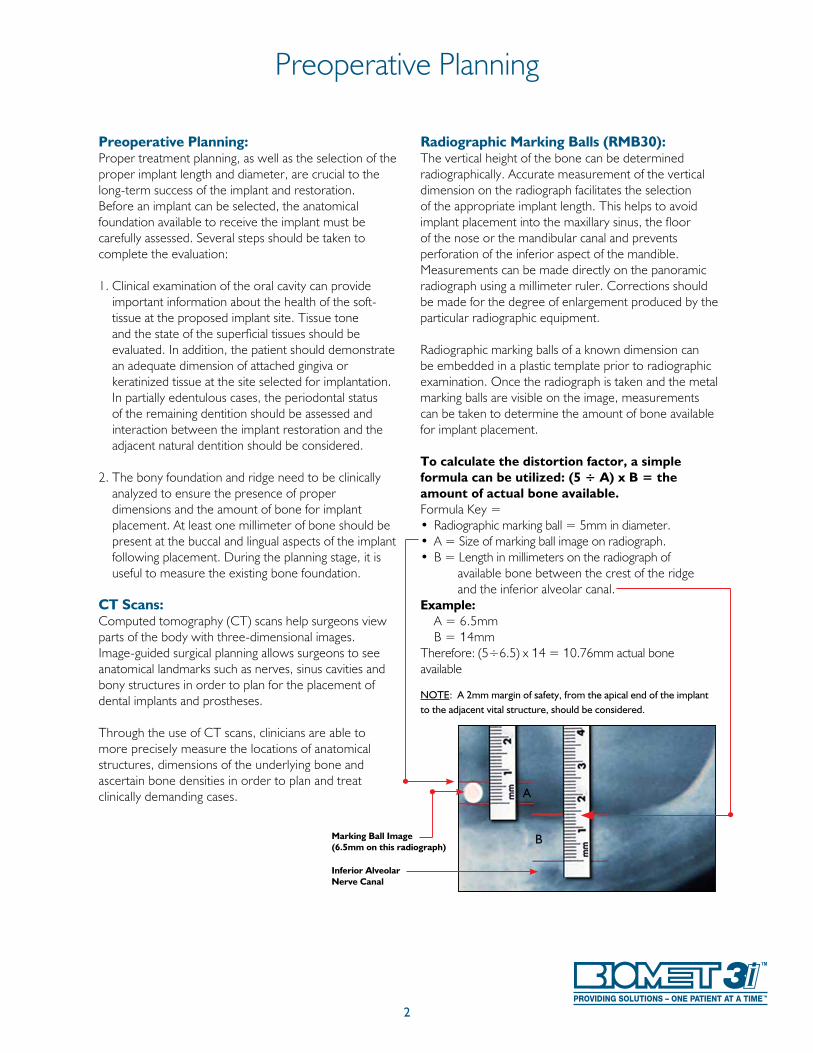
Radiographic Marking Balls (RMB30):The vertical height of the bone can be determined radiographically. Accurate measurement of the vertical dimension on the radiograph facilitates the selection of the appropriate implant length. This helps to avoid implant placement into the maxillary sinus, the floor of the nose or the mandibular canal and prevents perforation of the inferior aspect of the mandible. Measurements can be made directly on the panoramic radiograph using a millimeter ruler. Corrections should be made for the degree of enlargement produced by the particular radiographic equipment.
Radiographic marking balls of a known dimension can be embedded in a plastic template prior to radiographic examination. Once the radiograph is taken and the metal marking balls are visible on the image, measurements can be taken to determine the amount of bone available for implant placement.
To calculate the distortion factor, a simple formula can be utilized: (5 ÷ A) x B = the amount of actual bone available.Formula Key =• Radiographic marking ball = 5mm in diameter.• A = Size of marking ball image on radiograph.• B = Length in millimeters on the radiograph of available bone between the crest of the ridge and the inferior alveolar canal.Example: A = 6.5mm B = 14mmTherefore: (5÷6.5) x 14 = 10.76mm actual bone available
NOTE: A 2mm margin of safety, from the apical end of the implant to the adjacent vital structure, should be considered.
Inferior Alveolar Nerve Canal
Marking Ball Image(6.5mm on this radiograph)
A
B
3
Top-Down Treatment Planning
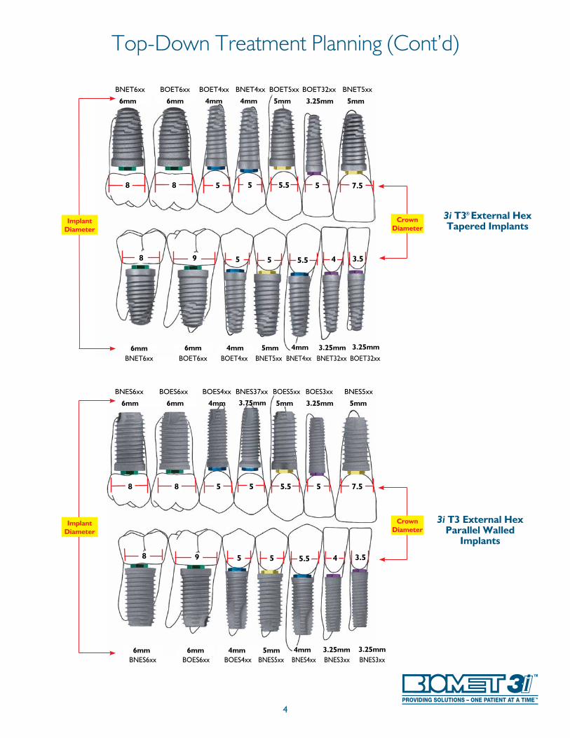
In its simplest form, top-down treatment planning refers to a guideline whereby the desired restorative result is considered first, leading to consideration of the appropriate prosthetic platform and subsequent implant selection based on bony anatomy and the size of the missing tooth.
A top-down treatment planning methodology will provide maximum biomechanical stability and allow for soft-tissue flaring by utilizing an implant with a prosthetic platform slightly smaller in diameter than the emergence diameter of the tooth being replaced. The wide selection of Implants allows clinicians to match the size of the prosthetic platform to the restoration it will eventually support, while allowing for different bone volumes and anatomical features at the
implant site. Implant and healing abutment selections are based upon the relationship of several key measurements:
• The emerging dimension of the crown in relation to the diameter of the prosthetic platform of the implant • The height and diameter of the intended restoration at the tissue exit point
• The bone volume at the implant site in relation to the diameter of the implant body
The Emergence Profile (EP®) Healing Abutment System consists of healing abutments of various diameters and heights for shaping the soft-tissue to replicate the geometry and gingival contours of natural dentition.
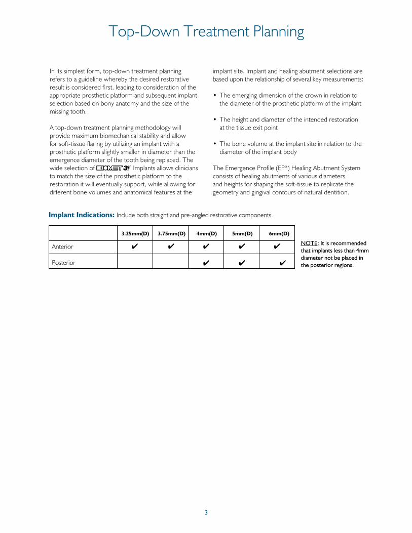
Anterior 4 4 4 4 4
Posterior 4 4 4
Implant Indications: Include both straight and pre-angled restorative components.
NOTE: It is recommended that implants less than 4mm diameter not be placed in the posterior regions.
3.25mm(D) 3.75mm(D) 4mm(D) 5mm(D) 6mm(D)
4
Top-Down Treatment Planning (Cont’d)
7.5
3.54
5.5 5
8 9 5 5.55
8 58 5
6mm 6mm 4mm 5mm
6mm 3.25mm4mm 5mm6mm
3.25mm 5mm3.75mm
3.25mm4mm
3i T3 External Hex Parallel Walled
Implants
BNES6xx BOES6xx BOES4xx BNES37xx BOES5xx BOES3xx BNES5xx
BNES6xx BOES6xx BOES4xx BNES5xx BNES4xx BNES3xx BNES3xx
Crown Diameter
Implant Diameter
7.5
3.54
5.5 5
8 9 5 5.55
8 58 5
6mm 6mm 4mm 5mm
6mm 3.25mm4mm 5mm6mm
3.25mm 5mm4mm
3.25mm4mm
3i T3® External Hex Tapered Implants
BNET6xx BOET6xx BOET4xx BNET4xx BOET5xx BOET32xx BNET5xx
BNET6xx BOET6xx BOET4xx BNET5xx BNET4xx BNET32xx BOET32xx
Crown Diameter
Implant Diameter
5
Surgical Precautions
Clinical Considerations:True bone contours can only be evaluated after tissue flaps have been reflected at the time of surgery or with preoperative high quality CT scans. Even if bone dimensions are painstakingly measured prior to surgery, the doctor and patient must accept the possibility that inadequate bone anatomy might be discovered during surgery and preclude implant placement.
During the presurgical planning phase, it is important to determine the interocclusal clearance - the actual space available between the alveolar crest and the opposing dentition - to confirm that the available space will accommodate the proposed abutment and the definitive crown restoration. The height required by the abutment may vary with the type of abutment; therefore, the surgeon and restorative dentist should carefully evaluate the abutment size. The definitive prosthesis should be conceptually designed prior to the placement of the implant.
Diagnostic casts can be used preoperatively to evaluate the residual ridge and to determine the position and angulation of all implants. These casts allow the clinician to evaluate the opposing dentition and its effect on the implant position. A surgical guide stent, which is critical for determining the precise position and angulation of the implant, can be constructed on the diagnostic cast.
Several software companies offer planning softwarethat allow clinicians to plan implant placement three-dimensionally in conjunction with CT scans. From plans created in these software packages, surgical guides can be made to aid in the pre-angulation and placement of implants.
To prevent damage to the bone tissue and to prevent compromising osseointegration by the bone overheating during high speed drilling, copious irrigation with sterile water or saline solution is mandatory during all drilling procedures.
Bone surgery utilizes a high-torque electric drilling unit that can be operated in forward and reverse modes at speeds ranging from 0 to 2000rpm, depending on the surgical requirements. Sharp instruments of the highest quality should be utilized during implant site preparation to reduce possible overheating and trauma to the bone. Minimizing trauma enhances the potential for successful osseointegration.
The time elapsed between surgical placement of the implant and definitive abutment placement can vary or be modified, depending on the quality of the bone at the implantation site, bony response to the implant surface and other implanted materials and the surgeon’s assessment of the patient’s bone density at the time of the surgical procedure. Extreme care must be taken to avoid excessive force being applied to the implant during this healing period.
6
Cleaning And Sterilization
Single use drills/burs are supplied sterile and should be properly disposed of after each procedure. Reusable drills/burs and instrumentation are supplied nonsterile and must be sterilized prior to use. Nonsterile items must be removed from the packaging before sterilization.
Multiple sterilizations may affect the flow of fluid through internally irrigated drills. The drills should be inspected following each sterilization cycle to determine if fluid flows through the irrigation ports. Although the surgical drills are constructed of stainless steel, these should be adequately dried prior to packaging for sterilization and again after the sterilization cycle. Reusable drills are recommended to be replaced after 15 osteotomy preparations, subject to the information below.
The end of life for surgical instruments is normally determined by wear and damage. Surgical instruments and instrument cases are susceptible to damage for a variety of reasons including prolonged use, misuse, rough or improper handling. Care must be taken to avoid compromising the intended performance of the instrument.
Visually inspect each instrument before and after each use for damage and/or wear.
To extend the useful life of Instruments, certain procedures should always be followed:
Cleaning: 1. After use, place drills into a beaker of plain water, mild
soap or specialized cleaning solution. 2. Rinse with tap water for a minimum of two minutes
while brushing with a soft bristled brush to remove visible debris. Clean the interior lumen with a thin wire to remove any remaining debris.
3. Place instruments in an ultrasonic bath containing enzymatic detergent for five minutes.* Scrub the instruments again with a soft bristled brush and ream the interior lumen to remove any remaining debris.
4. Rinse and flush the instruments for one minute using tap water.
5. Inspect visually for any remaining bone fragments or debris and scrub as necessary.
Sterilization: 6. Remove the bur block from the surgical tray. Scrub the
surgical tray and block with a soft bristle brush and mild soap. Rinse thoroughly.
7. Place the components into the surgical tray and pour ethyl alcohol (do not use rubbing alcohol) over the burs and tray to remove soap residue and minerals from the water. This step is important to help prevent corrosion and spotting. Let the components dry before wrapping.
8. Wrap the surgical tray in paper or autoclave-approved bags twice to prevent a tear of the outer packaging from contaminating sterile instruments.
9. Steam Gravity Sterilization Method Kits NPSDK0, NCATD0, NCATD0C, SGKIT, SGTIKIT:
Trays PSDT1, SGTRAY, SGTTRAY: Minimum forty (40) minutes at a temperature of 270 – 275ºF (132-135ºC)
All other Kits and Trays: Minimum twenty (20) minutes at a temperature of 270-275ºF (132-135ºC)
or Pre-vacuum Sterilization Method (All Kits)
Minimum four (4) minutes (four pulses) at a temperature of 270-275ºF (132-135ºC)
10. Post sterilization, devices should be thoroughly dried to mitigate the risk of stainless corrosion (30 minutes is typical). NOTE: Drying times may vary according to load size.
NOTE: Multiple sterilizations may affect the flow of fluid through internally irrigated burs. After each use, prior to the sterilization cycle, ream burs individually with wire to remove any bone fragments or debris that will prevent the flow of water. It is very important not to remove drills, instrumentation or the surgical tray from the autoclave until the “dry cycle” is complete. These guidelines DO NOT apply to the cleaning and sterilization of your powered instrumentation. Please follow your powered instrumentation manufacturer’s instructions.
Please refer to P-IFSCSS for complete instructions on the sterilization and care of stainless steel.
NOTE: Due to the individual clinical handling procedures, cleaning methods, bioburden levels, and other conditions, clinicians are responsible for proper sterilization of kits and instruments.
These recommendations have been validated by BIOMET 3i to obtainthe following:Cleaning: An average LOG10 reduction in tag spores to 4.58.Sterilization: A 10-6 SAL.
*ENZOL enzymatic detergent was used to validate this process per the manufacturer’s dilution recommendation.
7
Bone Density
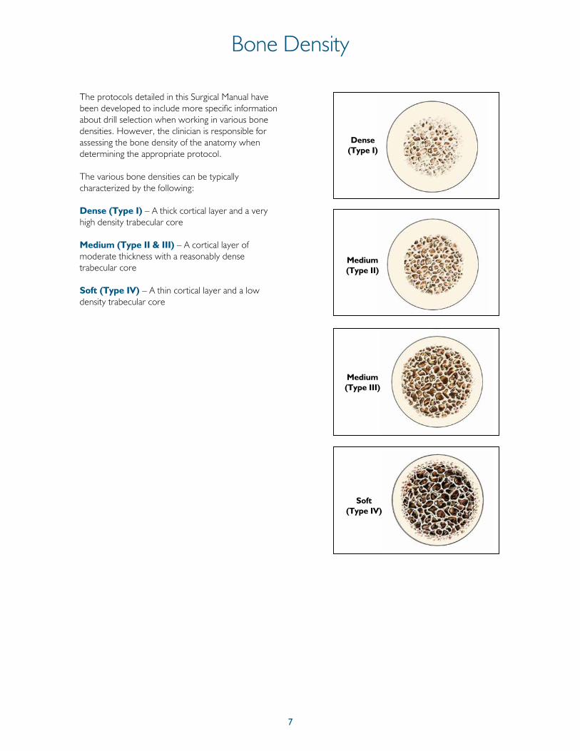
The protocols detailed in this Surgical Manual have been developed to include more specific information about drill selection when working in various bone densities. However, the clinician is responsible for assessing the bone density of the anatomy when determining the appropriate protocol.
The various bone densities can be typically characterized by the following:
Dense (Type I) – A thick cortical layer and a very high density trabecular core
Medium (Type II & III) – A cortical layer of moderate thickness with a reasonably dense trabecular core
Soft (Type IV) – A thin cortical layer and a low density trabecular core
Dense (Type I)
Medium (Type II)
Medium (Type III)
Soft (Type IV)
8
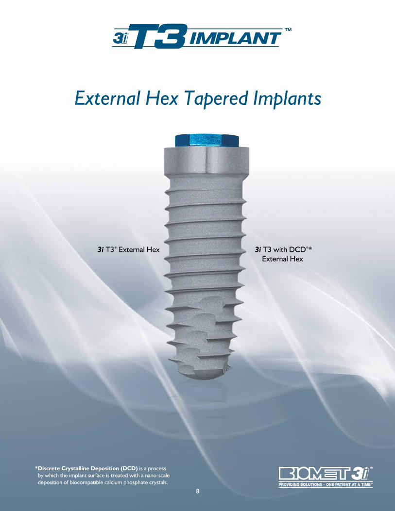
3i T3® External Hex 3i T3 with DCD®* External Hex
* Discrete Crystalline Deposition (DCD) is a process by which the implant surface is treated with a nano-scale deposition of biocompatible calcium phosphate crystals.
External Hex Tapered Implants
9
Why Tapered Implants Are Different3i T3
®
External Hex Tapered Implants
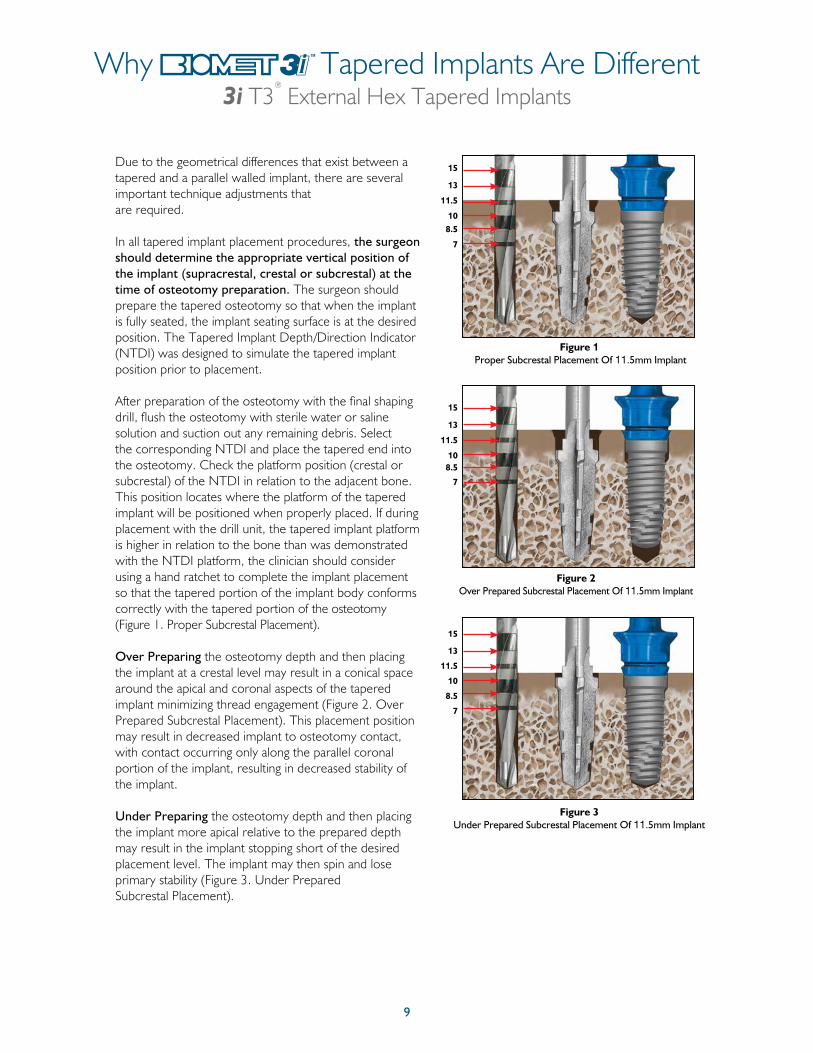
Due to the geometrical differences that exist between a tapered and a parallel walled implant, there are several important technique adjustments that are required.
In all tapered implant placement procedures, the surgeon should determine the appropriate vertical position of the implant (supracrestal, crestal or subcrestal) at the time of osteotomy preparation. The surgeon should prepare the tapered osteotomy so that when the implant is fully seated, the implant seating surface is at the desired position. The Tapered Implant Depth/Direction Indicator (NTDI) was designed to simulate the tapered implant position prior to placement.
After preparation of the osteotomy with the final shaping drill, flush the osteotomy with sterile water or saline solution and suction out any remaining debris. Select the corresponding NTDI and place the tapered end into the osteotomy. Check the platform position (crestal or subcrestal) of the NTDI in relation to the adjacent bone. This position locates where the platform of the tapered implant will be positioned when properly placed. If during placement with the drill unit, the tapered implant platform is higher in relation to the bone than was demonstrated with the NTDI platform, the clinician should consider using a hand ratchet to complete the implant placement so that the tapered portion of the implant body conforms correctly with the tapered portion of the osteotomy (Figure 1. Proper Subcrestal Placement).
Over Preparing the osteotomy depth and then placing the implant at a crestal level may result in a conical space around the apical and coronal aspects of the tapered implant minimizing thread engagement (Figure 2. Over Prepared Subcrestal Placement). This placement position may result in decreased implant to osteotomy contact, with contact occurring only along the parallel coronal portion of the implant, resulting in decreased stability of the implant.
Under Preparing the osteotomy depth and then placing the implant more apical relative to the prepared depth may result in the implant stopping short of the desired placement level. The implant may then spin and lose primary stability (Figure 3. Under Prepared Subcrestal Placement).
Figure 1 Proper Subcrestal Placement Of 11.5mm Implant
15
13
11.5
108.5
7
Figure 2Over Prepared Subcrestal Placement Of 11.5mm Implant
15
13
11.5
108.5
7
Figure 3Under Prepared Subcrestal Placement Of 11.5mm Implant
15
13
11.5
10
8.5
7
10
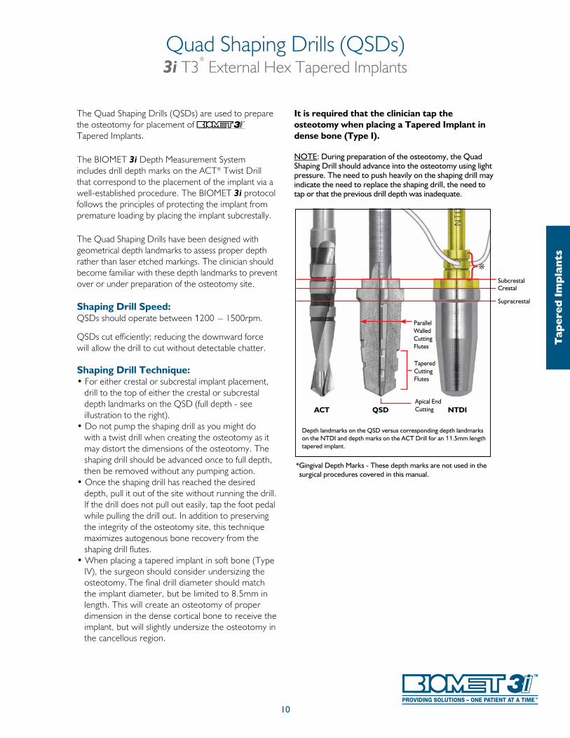
The Quad Shaping Drills (QSDs) are used to prepare the osteotomy for placement of Tapered Implants.
The BIOMET 3i Depth Measurement System includes drill depth marks on the ACT® Twist Drill that correspond to the placement of the implant via a well-established procedure. The BIOMET 3i protocol follows the principles of protecting the implant from premature loading by placing the implant subcrestally.
The Quad Shaping Drills have been designed with geometrical depth landmarks to assess proper depth rather than laser etched markings. The clinician should become familiar with these depth landmarks to prevent over or under preparation of the osteotomy site.
Shaping Drill Speed:QSDs should operate between 1200 – 1500rpm.
QSDs cut efficiently; reducing the downward force will allow the drill to cut without detectable chatter.
Shaping Drill Technique:• For either crestal or subcrestal implant placement,
drill to the top of either the crestal or subcrestal depth landmarks on the QSD (full depth - see illustration to the right).
• Do not pump the shaping drill as you might do with a twist drill when creating the osteotomy as it may distort the dimensions of the osteotomy. The shaping drill should be advanced once to full depth, then be removed without any pumping action.
• Once the shaping drill has reached the desired depth, pull it out of the site without running the drill. If the drill does not pull out easily, tap the foot pedal while pulling the drill out. In addition to preserving the integrity of the osteotomy site, this technique maximizes autogenous bone recovery from the shaping drill flutes.
• When placing a tapered implant in soft bone (Type IV), the surgeon should consider undersizing the osteotomy. The final drill diameter should match the implant diameter, but be limited to 8.5mm in length. This will create an osteotomy of proper dimension in the dense cortical bone to receive the implant, but will slightly undersize the osteotomy in the cancellous region.
It is required that the clinician tap the osteotomy when placing a Tapered Implant in dense bone (Type I).
NOTE: During preparation of the osteotomy, the Quad Shaping Drill should advance into the osteotomy using light pressure. The need to push heavily on the shaping drill may indicate the need to replace the shaping drill, the need to tap or that the previous drill depth was inadequate.
Quad Shaping Drills (QSDs)3i T3
®
External Hex Tapered Implants
Depth landmarks on the QSD versus corresponding depth landmarks on the NTDI and depth marks on the ACT Drill for an 11.5mm length tapered implant.
*{
QSD NTDI
Supracrestal
CrestalSubcrestal
Parallel Walled Cutting Flutes
Tapered Cutting Flutes
Apical End Cutting
* Gingival Depth Marks - These depth marks are not used in the surgical procedures covered in this manual.
ACT
Tap
ered
Im
pla
nts
11
Twist Drill Depth Marking System3i T3
®
External Hex Tapered Implants
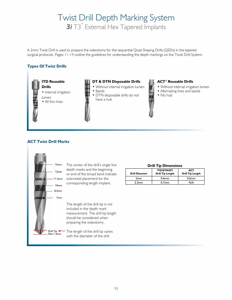
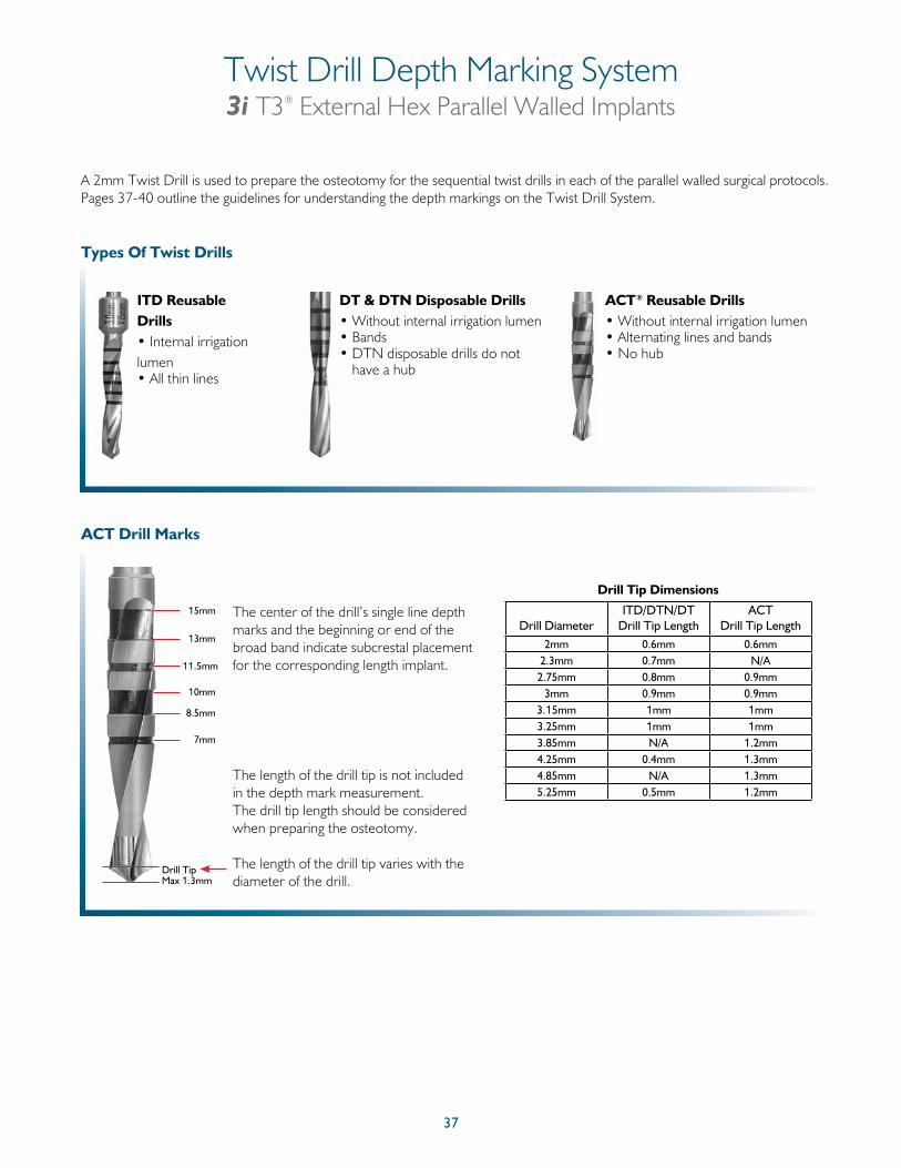
ITD Reusable Drills • Internal irrigation lumen • All thin lines
Types Of Twist Drills
DT & DTN Disposable Drills• Without internal irrigation lumen• Bands• DTN disposable drills do not
have a hub
ACT Twist Drill Marks
The length of the drill tip is not included in the depth mark measurement. The drill tip length should be considered when preparing the osteotomy.
The length of the drill tip varies with the diameter of the drill.
The center of the drill’s single line depth marks and the beginning or end of the broad band indicate subcrestal placement for the corresponding length implant.
Drill Tip Dimensions
8.5mm
7mm
Drill Tip
10mm
11.5mm
13mm
15mm
Max 1.3mm
ACT® Reusable Drills• Without internal irrigation lumen• Alternating lines and bands• No hub
Drill DiameterITD/DTN/DT
Drill Tip LengthACT
Drill Tip Length
2mm 0.6mm 0.6mm2.3mm 0.7mm N/A
A 2mm Twist Drill is used to prepare the osteotomy for the sequential Quad Shaping Drills (QSDs) in the tapered surgical protocols. Pages 11-14 outline the guidelines for understanding the depth markings on the Twist Drill System.
12
Twist Drill Depth Marking System (Cont’d)3i T3
®
External Hex Tapered Implants
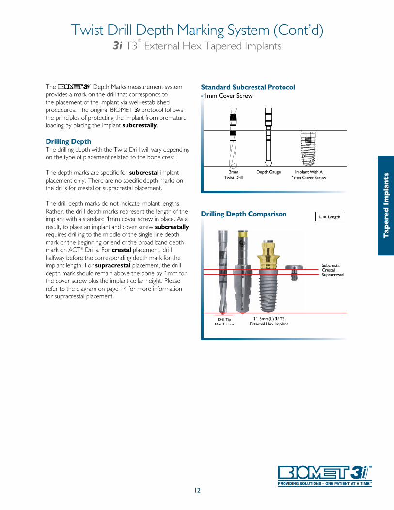
The Depth Marks measurement system provides a mark on the drill that corresponds to the placement of the implant via well-established procedures. The original BIOMET 3i protocol follows the principles of protecting the implant from premature loading by placing the implant subcrestally.
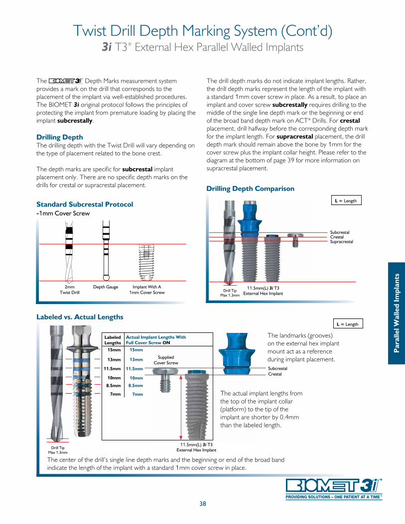
Drilling DepthThe drilling depth with the Twist Drill will vary depending on the type of placement related to the bone crest.
The depth marks are specific for subcrestal implant placement only. There are no specific depth marks on the drills for crestal or supracrestal placement.
The drill depth marks do not indicate implant lengths. Rather, the drill depth marks represent the length of the implant with a standard 1mm cover screw in place. As a result, to place an implant and cover screw subcrestally requires drilling to the middle of the single line depth mark or the beginning or end of the broad band depth mark on ACT® Drills. For crestal placement, drill halfway before the corresponding depth mark for the implant length. For supracrestal placement, the drill depth mark should remain above the bone by 1mm for the cover screw plus the implant collar height. Please refer to the diagram on page 14 for more information for supracrestal placement.
2mmTwist Drill
Depth Gauge Implant With A1mm Cover Screw
Standard Subcrestal Protocol -1mm Cover Screw
Drill TipMax 1.3mm
SubcrestalCrestal Supracrestal
Drilling Depth Comparison
11.5mm(L) 3i T3External Hex Implant
L = Length
Tap
ered
Im
pla
nts
13
Twist Drill Depth Marking System (Cont’d)3i T3
®
External Hex Tapered Implants
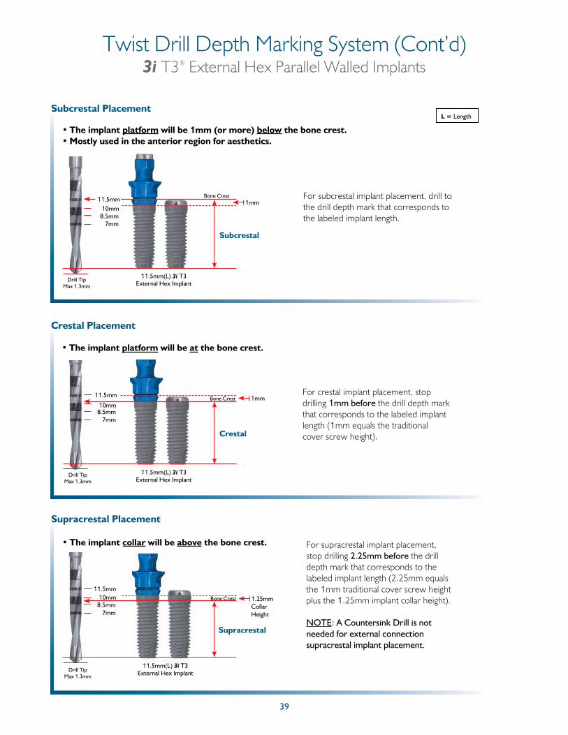
Subcrestal Placement
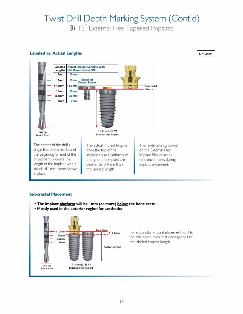
• The implant platform will be 1mm (or more) below the bone crest.• Mostly used in the anterior region for aesthetics
8.5mm7mm
Subcrestal
10mm1mm
Bone CrestFor subcrestal implant placement, drill to the drill depth mark that corresponds to the labeled implant length.
11.5mm
Drill TipMax 1.3mm
11.5mm(L) 3i T3External Hex Implant
L = LengthLabeled vs. Actual Lengths
The center of the drill’s single line depth marks and the beginning or end of the broad band indicate the length of the implant with a standard 1mm cover screw in place.
The actual implant lengths from the top of the implant collar (platform) to the tip of the implant are shorter by 0.4mm than the labeled length.
The landmarks (grooves) on the External Hex Implant Mount act as reference marks during implant placement.
11.5mm(L) 3i T3External Hex Implant
15mm
LabeledLengths
Actual Implant Lengths With Full Cover Screw ON
15mm
13mm
11.5mm
10mm
8.5mm
7mm
13mm
11.5mm
10mm
8.5mm
7mm
SubcrestalCrestal
Supplied Cover Screw
Drill TipMax 1.3mm
14
Twist Drill Depth Marking System (Cont’d)3i T3
®
External Hex Tapered Implants
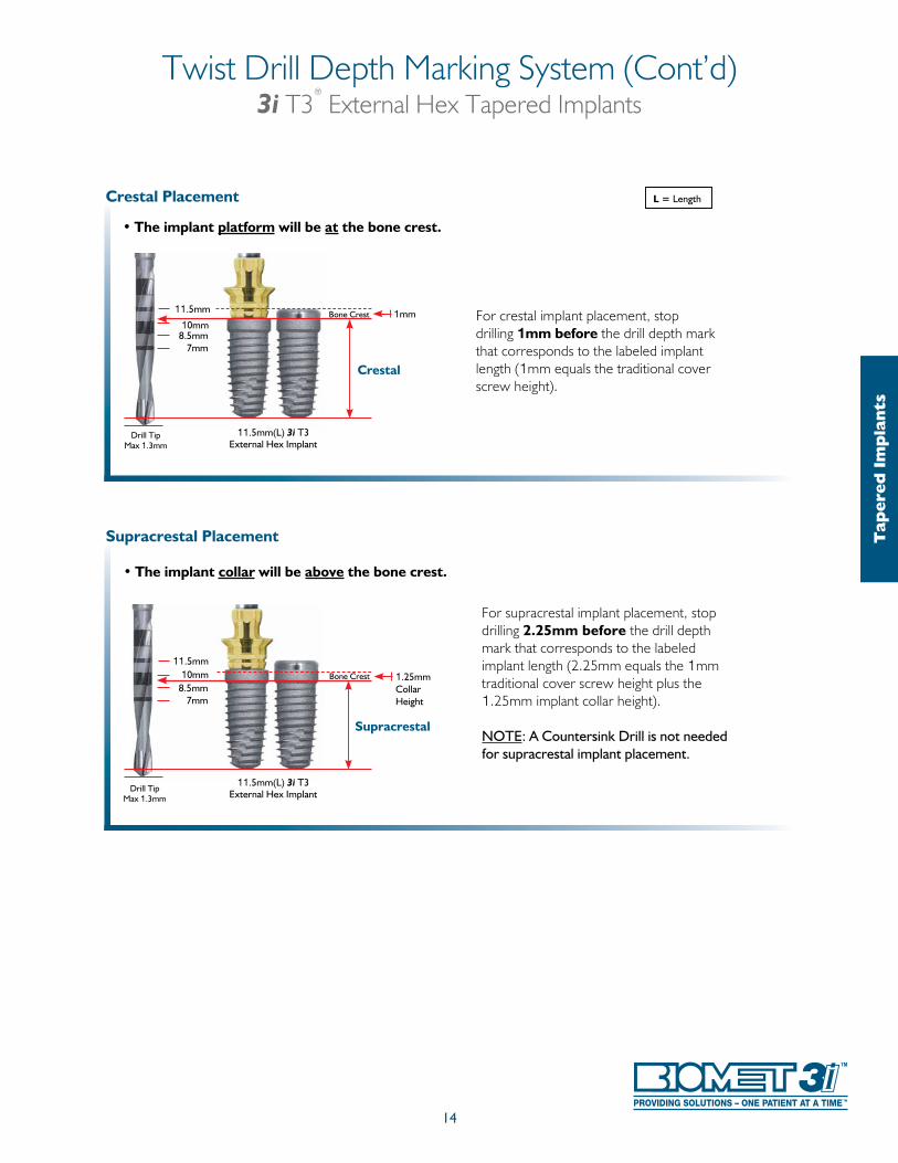
Crestal Placement
• The implant platform will be at the bone crest.
For crestal implant placement, stop drilling 1mm before the drill depth mark that corresponds to the labeled implant length (1mm equals the traditional cover screw height).
Drill TipMax 1.3mm
8.5mm7mm
Crestal
10mm1mmBone Crest11.5mm
11.5mm(L) 3i T3External Hex Implant
Supracrestal Placement
• The implant collar will be above the bone crest.
For supracrestal implant placement, stop drilling 2.25mm before the drill depth mark that corresponds to the labeled implant length (2.25mm equals the 1mm traditional cover screw height plus the 1.25mm implant collar height).
NOTE: A Countersink Drill is not needed for supracrestal implant placement.
Drill TipMax 1.3mm
8.5mm7mm
Supracrestal
10mm 1.25mm Collar Height
Bone Crest
11.5mm
11.5mm(L) 3i T3External Hex Implant
L = Length
Tap
ered
Im
pla
nts
15
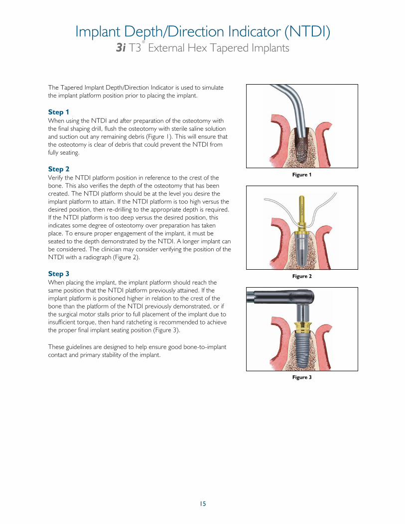
The Tapered Implant Depth/Direction Indicator is used to simulate the implant platform position prior to placing the implant.
Step 1When using the NTDI and after preparation of the osteotomy with the final shaping drill, flush the osteotomy with sterile saline solution and suction out any remaining debris (Figure 1). This will ensure that the osteotomy is clear of debris that could prevent the NTDI from fully seating.
Step 2Verify the NTDI platform position in reference to the crest of the bone. This also verifies the depth of the osteotomy that has been created. The NTDI platform should be at the level you desire the implant platform to attain. If the NTDI platform is too high versus the desired position, then re-drilling to the appropriate depth is required. If the NTDI platform is too deep versus the desired position, this indicates some degree of osteotomy over preparation has taken place. To ensure proper engagement of the implant, it must be seated to the depth demonstrated by the NTDI. A longer implant can be considered. The clinician may consider verifying the position of the NTDI with a radiograph (Figure 2).
Step 3When placing the implant, the implant platform should reach the same position that the NTDI platform previously attained. If the implant platform is positioned higher in relation to the crest of the bone than the platform of the NTDI previously demonstrated, or if the surgical motor stalls prior to full placement of the implant due to insufficient torque, then hand ratcheting is recommended to achieve the proper final implant seating position (Figure 3).
These guidelines are designed to help ensure good bone-to-implant contact and primary stability of the implant.
Figure 1
Figure 2
Figure 3
Implant Depth/Direction Indicator (NTDI)3i T3
®
External Hex Tapered Implants
16
Implant Bone Taps And Bone Tap Kit (NTAPK)3i T3
®
External Hex Tapered Implants
Dense Bone Taps
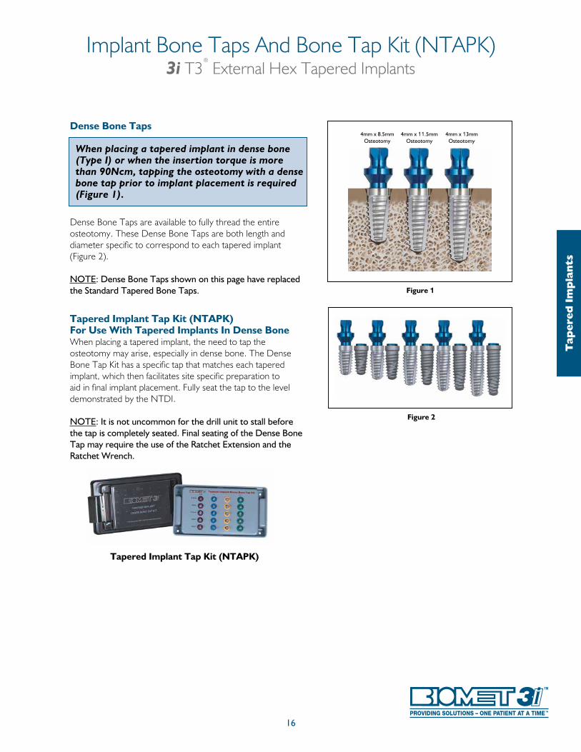
When placing a tapered implant in dense bone (Type I) or when the insertion torque is more than 90Ncm, tapping the osteotomy with a dense bone tap prior to implant placement is required (Figure 1).
Dense Bone Taps are available to fully thread the entire osteotomy. These Dense Bone Taps are both length and diameter specific to correspond to each tapered implant (Figure 2).
NOTE: Dense Bone Taps shown on this page have replaced the Standard Tapered Bone Taps.
Tapered Implant Tap Kit (NTAPK)For Use With Tapered Implants In Dense BoneWhen placing a tapered implant, the need to tap the osteotomy may arise, especially in dense bone. The Dense Bone Tap Kit has a specific tap that matches each tapered implant, which then facilitates site specific preparation to aid in final implant placement. Fully seat the tap to the level demonstrated by the NTDI.
NOTE: It is not uncommon for the drill unit to stall before the tap is completely seated. Final seating of the Dense Bone Tap may require the use of the Ratchet Extension and the Ratchet Wrench.
4mm x 8.5mmOsteotomy
4mm x 13mmOsteotomy
4mm x 11.5mmOsteotomy
Figure 1
Figure 2
Tapered Implant Tap Kit (NTAPK)T
aper
ed I
mp
lan
ts

17
Coordinating The Use Of The Surgical Tray With The Surgical Manual Illustrations:
The Surgical Tray (QNTSK) for tapered implants is numbered to indicate the appropriate steps of the implant placement protocol. The following illustrated implant placement protocol uses the same sequence.
Close-up view of the Surgical Tray illustrating numbering sequence.
Implant Surgical Tray (QNTSK)3i T3
®
External Hex Tapered Implants
18
20mm
18mm
15mm
13mm
11.5mm10mm8.5mm7mm
ACT® Twist DrillDepth Marks
Drill Tip Max 1.3mm
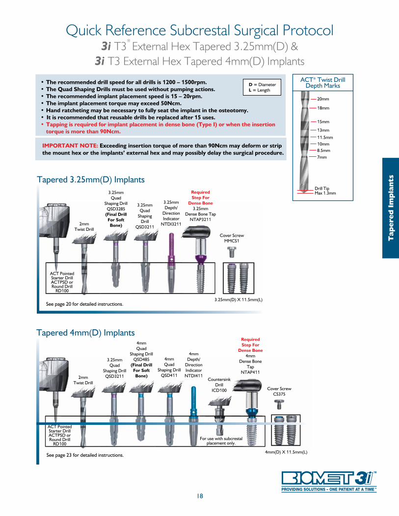
Quick Reference Subcrestal Surgical Protocol3i T3
®
External Hex Tapered 3.25mm(D) & 3i T3 External Hex Tapered 4mm(D) Implants
Tap
ered
Im
pla
nts
See page 20 for detailed instructions.
Tapered 3.25mm(D) Implants
2mmTwist Drill
3.25mmDepth/
Direction Indicator
NTDI3211
Cover ScrewMMCS1
3.25mmQuad
Shaping Drill
QSD3211
RequiredStep For
Dense Bone3.25mm
Dense Bone TapNTAP3211
3.25mm(D) X 11.5mm(L)
ACT Pointed Starter DrillACTPSD or Round Drill
RD100
3.25mmQuad
Shaping DrillQSD3285
(Final Drill For Soft Bone)
• The recommended drill speed for all drills is 1200 – 1500rpm.• The Quad Shaping Drills must be used without pumping actions.• The recommended implant placement speed is 15 – 20rpm.• The implant placement torque may exceed 50Ncm.• Hand ratcheting may be necessary to fully seat the implant in the osteotomy.• It is recommended that reusable drills be replaced after 15 uses.• Tapping is required for implant placement in dense bone (Type I) or when the insertion
torque is more than 90Ncm.
IMPORTANT NOTE: Exceeding insertion torque of more than 90Ncm may deform or strip the mount hex or the implants’ external hex and may possibly delay the surgical procedure.
D = DiameterL = Length
See page 23 for detailed instructions.
Tapered 4mm(D) Implants
2mmTwist Drill
4mmQuad
Shaping DrillQSD411
4mmDepth/
Direction IndicatorNTDI411
3.25mmQuad
Shaping DrillQSD3211
4mmQuad
Shaping DrillQSD485
(Final Drill For Soft Bone)
4mm(D) X 11.5mm(L)
ACT Pointed Starter DrillACTPSD or Round Drill
RD100
RequiredStep For
Dense Bone4mm
Dense Bone Tap
NTAP411
Cover ScrewCS375
CountersinkDrill
ICD100
For use with subcrestal placement only.
• The recommended drill speed for all drills is 1200 – 1500rpm.• The Quad Shaping Drills must be used without pumping actions.• The recommended implant placement speed is 15 – 20rpm.• The implant placement torque may exceed 50Ncm.• Hand ratcheting may be necessary to fully seat the implant in the osteotomy.• It is recommended that reusable drills be replaced after 15 uses.• Tapping is required for implant placement in dense bone (Type I) or when the
insertion torque is more than 90Ncm.
IMPORTANT NOTE: Exceeding insertion torque of more than 90Ncm may deform or strip the mount hex or the implant’s external hex and may possibly delay the surgical procedure.
19
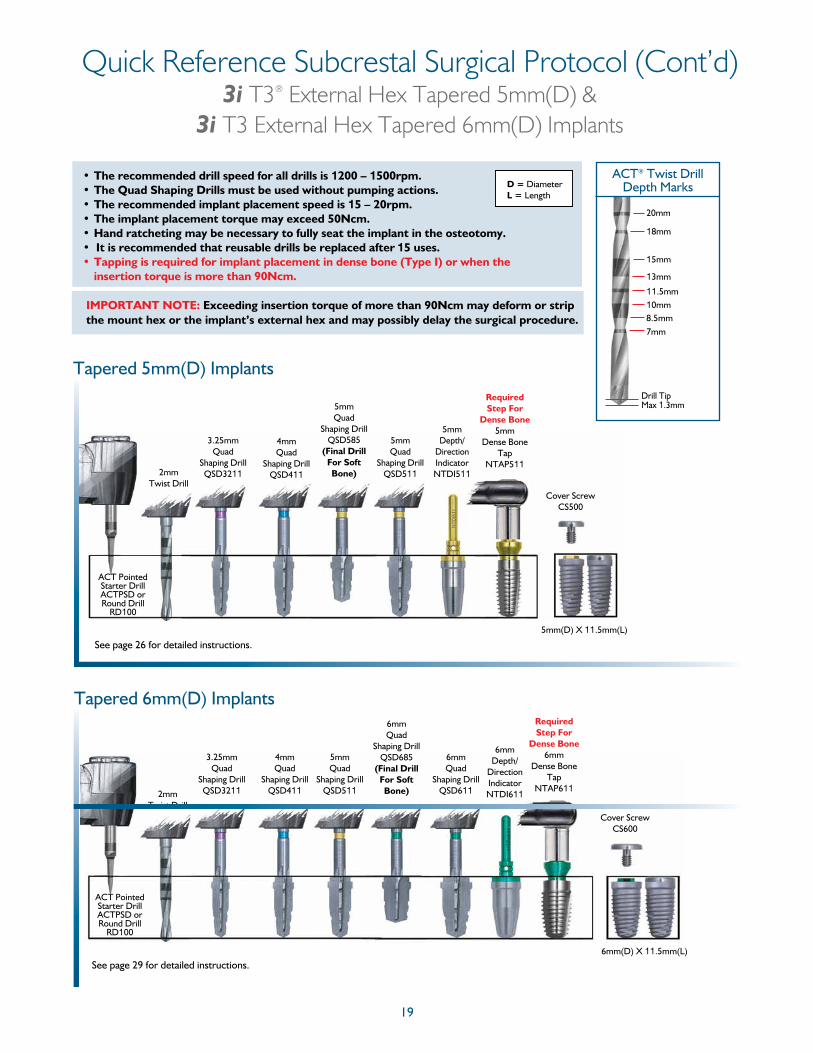
Quick Reference Subcrestal Surgical Protocol (Cont’d)3i T3® External Hex Tapered 5mm(D) &
3i T3 External Hex Tapered 6mm(D) Implants
Tapered 5mm(D) Implants
2mmTwist Drill
4mmQuad
Shaping DrillQSD411
5mmQuad
Shaping DrillQSD585
(Final Drill For Soft Bone)
5mmQuad
Shaping DrillQSD511
Cover ScrewCS500
3.25mmQuad
Shaping DrillQSD3211
5mm(D) X 11.5mm(L)
ACT Pointed Starter DrillACTPSD or Round Drill
RD100
5mmDepth/
Direction IndicatorNTDI511
Required Step For
Dense Bone5mm
Dense Bone Tap
NTAP511
See page 26 for detailed instructions.
D = DiameterL = Length
20mm
18mm
15mm
13mm
11.5mm10mm8.5mm7mm
ACT® Twist DrillDepth Marks
Drill Tip Max 1.3mm
Tapered 6mm(D) Implants
2mmTwist Drill
4mmQuad
Shaping DrillQSD411
5mmQuad
Shaping DrillQSD511
6mmQuad
Shaping DrillQSD611
6mmDepth/
Direction IndicatorNTDI611
Cover ScrewCS600
3.25mmQuad
Shaping DrillQSD3211
6mm(D) X 11.5mm(L)
ACT Pointed Starter DrillACTPSD or Round Drill
RD100
Required Step For
Dense Bone6mm
Dense Bone Tap
NTAP611
See page 29 for detailed instructions.
6mmQuad
Shaping DrillQSD685
(Final Drill For Soft Bone)
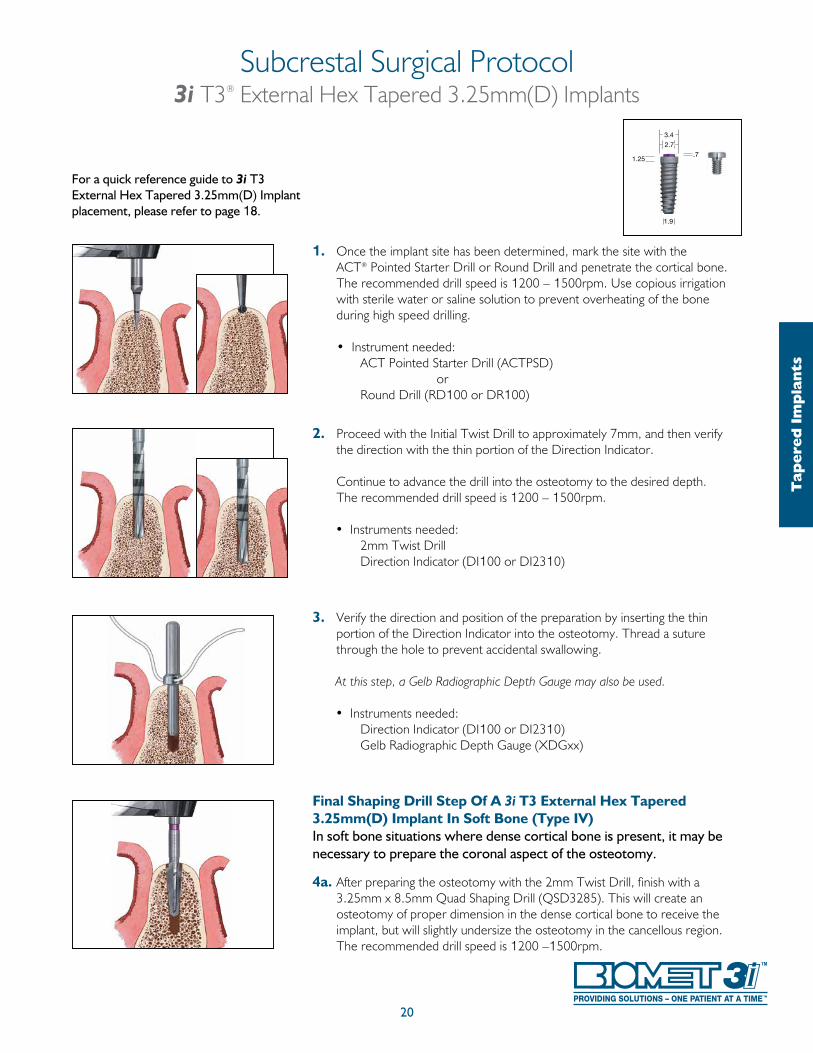
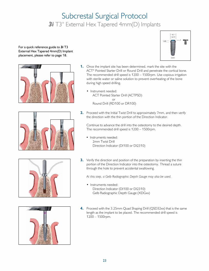
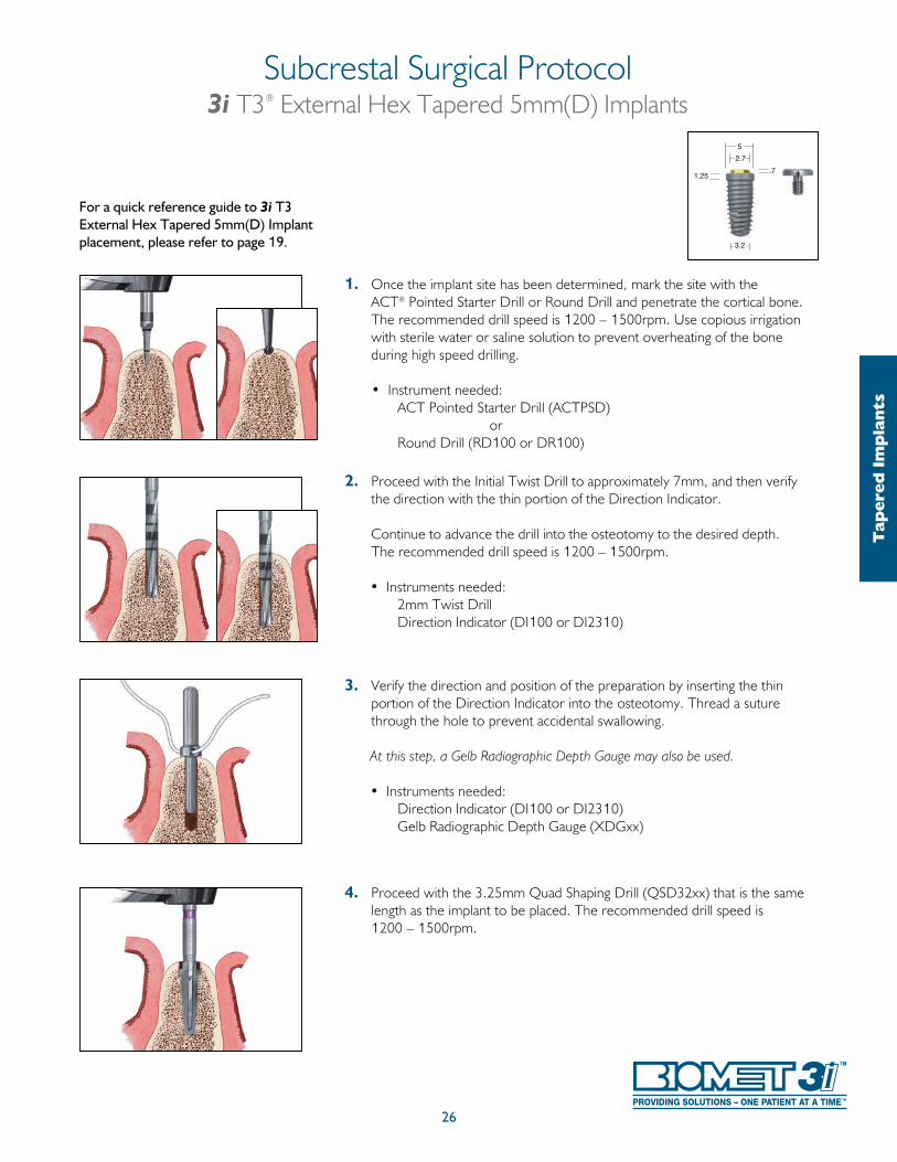
1. Once the implant site has been determined, mark the site with the ACT® Pointed Starter Drill or Round Drill and penetrate the cortical bone.
The recommended drill speed is 1200 – 1500rpm. Use copious irrigation with sterile water or saline solution to prevent overheating of the bone during high speed drilling.
• Instrument needed: ACT Pointed Starter Drill (ACTPSD) or Round Drill (RD100 or DR100)
2. Proceed with the Initial Twist Drill to approximately 7mm, and then verify the direction with the thin portion of the Direction Indicator.
Continue to advance the drill into the osteotomy to the desired depth. The recommended drill speed is 1200 – 1500rpm.
• Instruments needed: 2mm Twist Drill Direction Indicator (DI100 or DI2310)
3. Verify the direction and position of the preparation by inserting the thin portion of the Direction Indicator into the osteotomy. Thread a suture through the hole to prevent accidental swallowing.
At this step, a Gelb Radiographic Depth Gauge may also be used.
• Instruments needed: Direction Indicator (DI100 or DI2310) Gelb Radiographic Depth Gauge (XDGxx)
Final Shaping Drill Step Of A 3i T3 External Hex Tapered 3.25mm(D) Implant In Soft Bone (Type IV)In soft bone situations where dense cortical bone is present, it may be necessary to prepare the coronal aspect of the osteotomy.
4a. After preparing the osteotomy with the 2mm Twist Drill, finish with a 3.25mm x 8.5mm Quad Shaping Drill (QSD3285). This will create an osteotomy of proper dimension in the dense cortical bone to receive the implant, but will slightly undersize the osteotomy in the cancellous region. The recommended drill speed is 1200 –1500rpm.
For a quick reference guide to 3i T3 External Hex Tapered 3.25mm(D) Implant placement, please refer to page 18.
Subcrestal Surgical Protocol3i T3® External Hex Tapered 3.25mm(D) Implants
20
Tap
ered
Im
pla
nts
3.4
1.25
1.9
2.7
.7
21
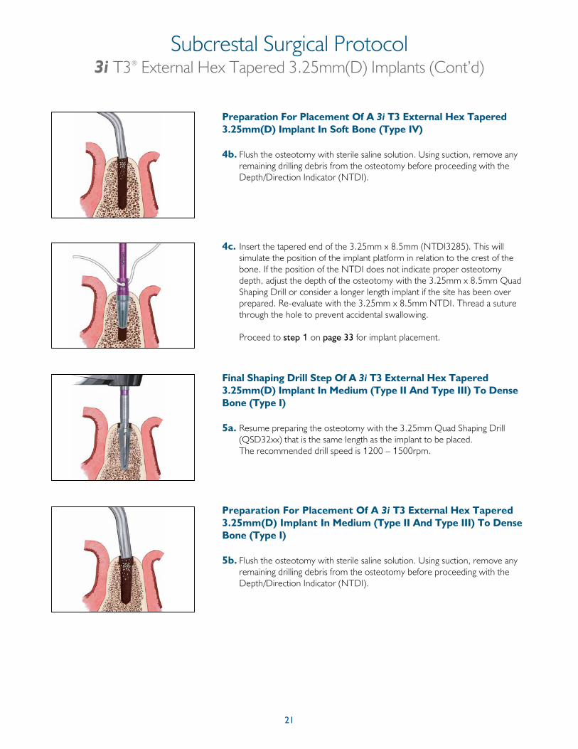
Preparation For Placement Of A 3i T3 External Hex Tapered 3.25mm(D) Implant In Soft Bone (Type IV)
4b. Flush the osteotomy with sterile saline solution. Using suction, remove any remaining drilling debris from the osteotomy before proceeding with the Depth/Direction Indicator (NTDI).
4c. Insert the tapered end of the 3.25mm x 8.5mm (NTDI3285). This will simulate the position of the implant platform in relation to the crest of the bone. If the position of the NTDI does not indicate proper osteotomy depth, adjust the depth of the osteotomy with the 3.25mm x 8.5mm Quad Shaping Drill or consider a longer length implant if the site has been over prepared. Re-evaluate with the 3.25mm x 8.5mm NTDI. Thread a suture through the hole to prevent accidental swallowing.
Proceed to step 1 on page 33 for implant placement.
Final Shaping Drill Step Of A 3i T3 External Hex Tapered 3.25mm(D) Implant In Medium (Type II And Type III) To Dense Bone (Type I)
5a. Resume preparing the osteotomy with the 3.25mm Quad Shaping Drill (QSD32xx) that is the same length as the implant to be placed. The recommended drill speed is 1200 – 1500rpm.
Preparation For Placement Of A 3i T3 External Hex Tapered 3.25mm(D) Implant In Medium (Type II And Type III) To Dense Bone (Type I)
5b. Flush the osteotomy with sterile saline solution. Using suction, remove any remaining drilling debris from the osteotomy before proceeding with the Depth/Direction Indicator (NTDI).
Subcrestal Surgical Protocol3i T3® External Hex Tapered 3.25mm(D) Implants (Cont’d)
22
Required Step
Subcrestal Surgical Protocol3i T3® External Hex Tapered 3.25mm(D) Implants (Cont’d)
Tap
ered
Im
pla
nts
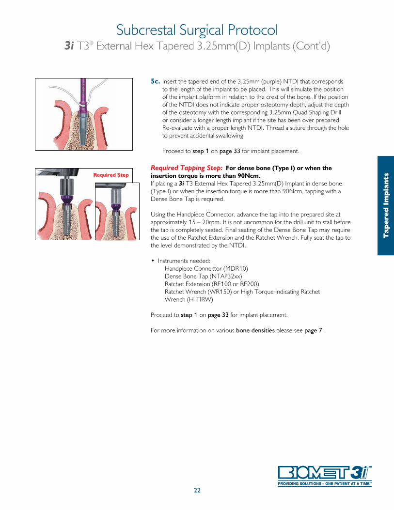
5c. Insert the tapered end of the 3.25mm (purple) NTDI that corresponds to the length of the implant to be placed. This will simulate the position of the implant platform in relation to the crest of the bone. If the position of the NTDI does not indicate proper osteotomy depth, adjust the depth of the osteotomy with the corresponding 3.25mm Quad Shaping Drill or consider a longer length implant if the site has been over prepared. Re-evaluate with a proper length NTDI. Thread a suture through the hole to prevent accidental swallowing.
Proceed to step 1 on page 33 for implant placement.
Required Tapping Step: For dense bone (Type I) or when the insertion torque is more than 90Ncm.If placing a 3i T3 External Hex Tapered 3.25mm(D) Implant in dense bone (Type I) or when the insertion torque is more than 90Ncm, tapping with a Dense Bone Tap is required.
Using the Handpiece Connector, advance the tap into the prepared site atapproximately 15 – 20rpm. It is not uncommon for the drill unit to stall before the tap is completely seated. Final seating of the Dense Bone Tap may require the use of the Ratchet Extension and the Ratchet Wrench. Fully seat the tap to the level demonstrated by the NTDI.
• Instruments needed: Handpiece Connector (MDR10) Dense Bone Tap (NTAP32xx) Ratchet Extension (RE100 or RE200) Ratchet Wrench (WR150) or High Torque Indicating Ratchet Wrench (H-TIRW) Proceed to step 1 on page 33 for implant placement.
For more information on various bone densities please see page 7.
23
Subcrestal Surgical Protocol3i T3® External Hex Tapered 4mm(D) Implants
1. Once the implant site has been determined, mark the site with the ACT® Pointed Starter Drill or Round Drill and penetrate the cortical bone. The recommended drill speed is 1200 – 1500rpm. Use copious irrigation with sterile water or saline solution to prevent overheating of the bone during high speed drilling.
• Instrument needed: ACT Pointed Starter Drill (ACTPSD) or Round Drill (RD100 or DR100)
2. Proceed with the Initial Twist Drill to approximately 7mm, and then verify the direction with the thin portion of the Direction Indicator.
Continue to advance the drill into the osteotomy to the desired depth. The recommended drill speed is 1200 – 1500rpm.
• Instruments needed: 2mm Twist Drill Direction Indicator (DI100 or DI2310)
3. Verify the direction and position of the preparation by inserting the thin portion of the Direction Indicator into the osteotomy. Thread a suture through the hole to prevent accidental swallowing.
At this step, a Gelb Radiographic Depth Gauge may also be used.
• Instruments needed: Direction Indicator (DI100 or DI2310) Gelb Radiographic Depth Gauge (XDGxx)
4. Proceed with the 3.25mm Quad Shaping Drill (QSD32xx) that is the same length as the implant to be placed. The recommended drill speed is 1200 – 1500rpm.
For a quick reference guide to 3i T3 External Hex Tapered 4mm(D) Implant placement, please refer to page 18.
1.25
2.4
4.1
2.7
.7
24
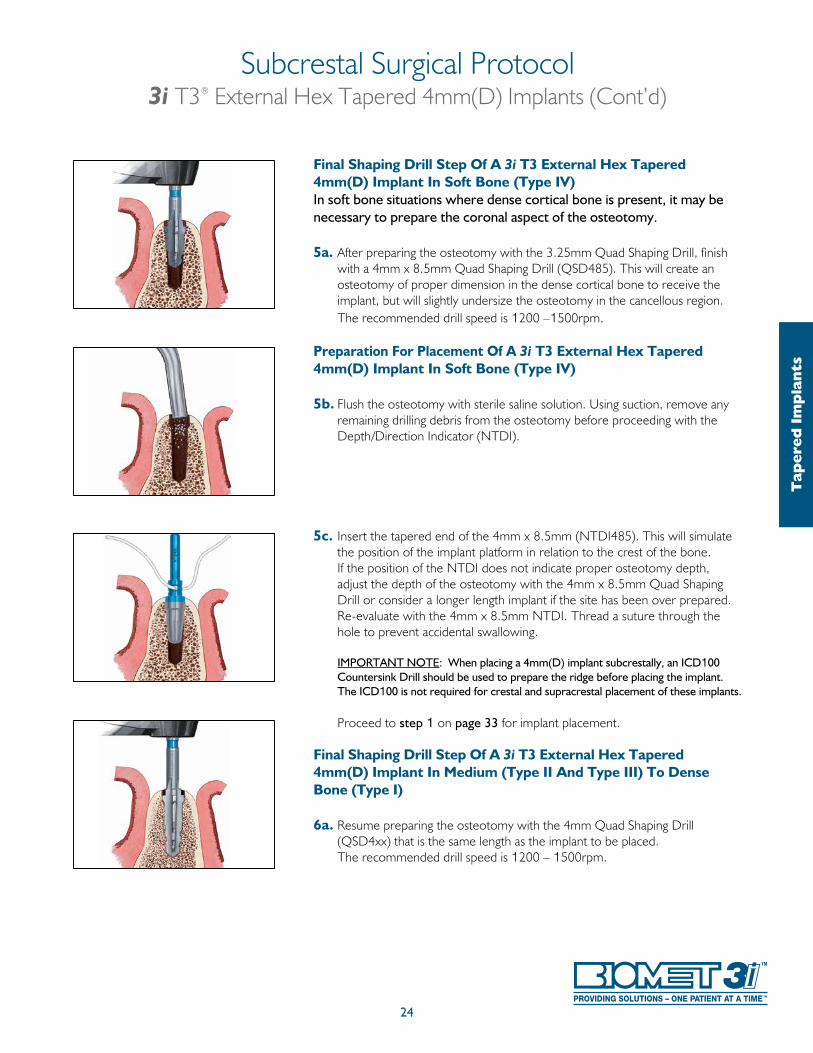
Final Shaping Drill Step Of A 3i T3 External Hex Tapered 4mm(D) Implant In Soft Bone (Type IV)In soft bone situations where dense cortical bone is present, it may be necessary to prepare the coronal aspect of the osteotomy.
5a. After preparing the osteotomy with the 3.25mm Quad Shaping Drill, finish with a 4mm x 8.5mm Quad Shaping Drill (QSD485). This will create an osteotomy of proper dimension in the dense cortical bone to receive the implant, but will slightly undersize the osteotomy in the cancellous region. The recommended drill speed is 1200 –1500rpm.
Preparation For Placement Of A 3i T3 External Hex Tapered 4mm(D) Implant In Soft Bone (Type IV)
5b. Flush the osteotomy with sterile saline solution. Using suction, remove any remaining drilling debris from the osteotomy before proceeding with the Depth/Direction Indicator (NTDI).
5c. Insert the tapered end of the 4mm x 8.5mm (NTDI485). This will simulate the position of the implant platform in relation to the crest of the bone. If the position of the NTDI does not indicate proper osteotomy depth, adjust the depth of the osteotomy with the 4mm x 8.5mm Quad Shaping Drill or consider a longer length implant if the site has been over prepared. Re-evaluate with the 4mm x 8.5mm NTDI. Thread a suture through the hole to prevent accidental swallowing.
IMPORTANT NOTE: When placing a 4mm(D) implant subcrestally, an ICD100 Countersink Drill should be used to prepare the ridge before placing the implant. The ICD100 is not required for crestal and supracrestal placement of these implants.
Proceed to step 1 on page 33 for implant placement.
Final Shaping Drill Step Of A 3i T3 External Hex Tapered 4mm(D) Implant In Medium (Type II And Type III) To Dense Bone (Type I)
6a. Resume preparing the osteotomy with the 4mm Quad Shaping Drill (QSD4xx) that is the same length as the implant to be placed. The recommended drill speed is 1200 – 1500rpm.
Subcrestal Surgical Protocol3i T3® External Hex Tapered 4mm(D) Implants (Cont’d)
Tap
ered
Im
pla
nts
25
Preparation For Placement Of A 3i T3 Eternal Hex Tapered 4mm(D) Implant In Medium (Type II And Type III) To Dense Bone (Type I)
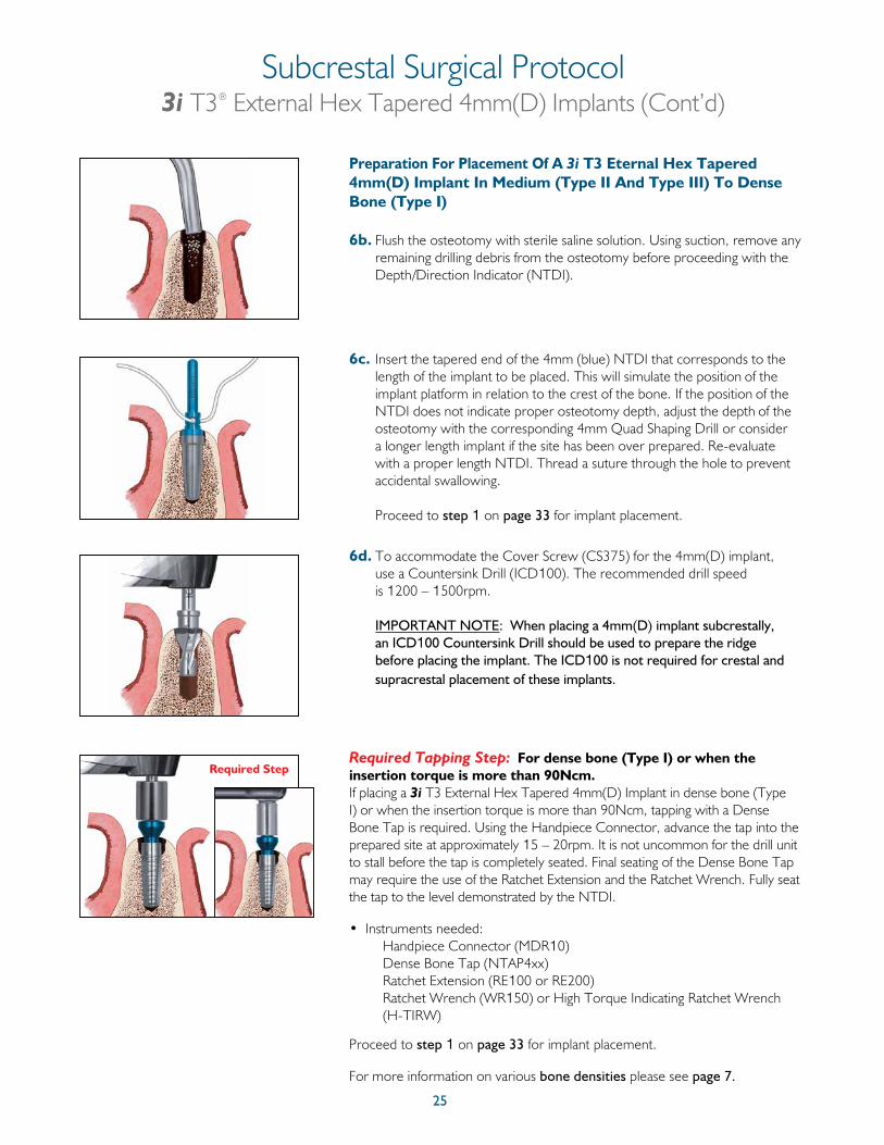
6b. Flush the osteotomy with sterile saline solution. Using suction, remove any remaining drilling debris from the osteotomy before proceeding with the Depth/Direction Indicator (NTDI).
6c. Insert the tapered end of the 4mm (blue) NTDI that corresponds to the length of the implant to be placed. This will simulate the position of the implant platform in relation to the crest of the bone. If the position of the NTDI does not indicate proper osteotomy depth, adjust the depth of the osteotomy with the corresponding 4mm Quad Shaping Drill or consider a longer length implant if the site has been over prepared. Re-evaluate with a proper length NTDI. Thread a suture through the hole to prevent accidental swallowing.
Proceed to step 1 on page 33 for implant placement.
6d. To accommodate the Cover Screw (CS375) for the 4mm(D) implant, use a Countersink Drill (ICD100). The recommended drill speed is 1200 – 1500rpm.
IMPORTANT NOTE: When placing a 4mm(D) implant subcrestally, an ICD100 Countersink Drill should be used to prepare the ridge before placing the implant. The ICD100 is not required for crestal and supracrestal placement of these implants.
Required Tapping Step: For dense bone (Type I) or when the insertion torque is more than 90Ncm.If placing a 3i T3 External Hex Tapered 4mm(D) Implant in dense bone (Type I) or when the insertion torque is more than 90Ncm, tapping with a Dense Bone Tap is required. Using the Handpiece Connector, advance the tap into the prepared site at approximately 15 – 20rpm. It is not uncommon for the drill unit to stall before the tap is completely seated. Final seating of the Dense Bone Tap may require the use of the Ratchet Extension and the Ratchet Wrench. Fully seat the tap to the level demonstrated by the NTDI.
• Instruments needed: Handpiece Connector (MDR10) Dense Bone Tap (NTAP4xx) Ratchet Extension (RE100 or RE200) Ratchet Wrench (WR150) or High Torque Indicating Ratchet Wrench (H-TIRW)
Proceed to step 1 on page 33 for implant placement.
For more information on various bone densities please see page 7.
Required Step
Subcrestal Surgical Protocol3i T3® External Hex Tapered 4mm(D) Implants (Cont’d)
26
For a quick reference guide to 3i T3 External Hex Tapered 5mm(D) Implant placement, please refer to page 19.
1. Once the implant site has been determined, mark the site with the ACT® Pointed Starter Drill or Round Drill and penetrate the cortical bone. The recommended drill speed is 1200 – 1500rpm. Use copious irrigation with sterile water or saline solution to prevent overheating of the bone during high speed drilling.
• Instrument needed: ACT Pointed Starter Drill (ACTPSD) or Round Drill (RD100 or DR100)
2. Proceed with the Initial Twist Drill to approximately 7mm, and then verify the direction with the thin portion of the Direction Indicator.
Continue to advance the drill into the osteotomy to the desired depth. The recommended drill speed is 1200 – 1500rpm.
• Instruments needed: 2mm Twist Drill Direction Indicator (DI100 or DI2310)
3. Verify the direction and position of the preparation by inserting the thin portion of the Direction Indicator into the osteotomy. Thread a suture through the hole to prevent accidental swallowing.
At this step, a Gelb Radiographic Depth Gauge may also be used.
• Instruments needed: Direction Indicator (DI100 or DI2310) Gelb Radiographic Depth Gauge (XDGxx)
4. Proceed with the 3.25mm Quad Shaping Drill (QSD32xx) that is the same length as the implant to be placed. The recommended drill speed is 1200 – 1500rpm.
Subcrestal Surgical Protocol3i T3® External Hex Tapered 5mm(D) Implants
Tap
ered
Im
pla
nts
3.2
1.25
5
2.7
.7
27
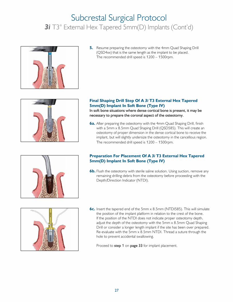
5. Resume preparing the osteotomy with the 4mm Quad Shaping Drill (QSD4xx) that is the same length as the implant to be placed.
The recommended drill speed is 1200 – 1500rpm.
Final Shaping Drill Step Of A 3i T3 External Hex Tapered 5mm(D) Implant In Soft Bone (Type IV)In soft bone situations where dense cortical bone is present, it may be necessary to prepare the coronal aspect of the osteotomy.
6a. After preparing the osteotomy with the 4mm Quad Shaping Drill, finish with a 5mm x 8.5mm Quad Shaping Drill (QSD585). This will create an osteotomy of proper dimension in the dense cortical bone to receive the implant, but will slightly undersize the osteotomy in the cancellous region. The recommended drill speed is 1200 – 1500rpm.
Preparation For Placement Of A 3i T3 External Hex Tapered 5mm(D) Implant In Soft Bone (Type IV)
6b. Flush the osteotomy with sterile saline solution. Using suction, remove any remaining drilling debris from the osteotomy before proceeding with the Depth/Direction Indicator (NTDI).
6c. Insert the tapered end of the 5mm x 8.5mm (NTDI585). This will simulate the position of the implant platform in relation to the crest of the bone. If the position of the NTDI does not indicate proper osteotomy depth, adjust the depth of the osteotomy with the 5mm x 8.5mm Quad Shaping Drill or consider a longer length implant if the site has been over prepared. Re-evaluate with the 5mm x 8.5mm NTDI. Thread a suture through the hole to prevent accidental swallowing.
Proceed to step 1 on page 33 for implant placement.
Subcrestal Surgical Protocol3i T3® External Hex Tapered 5mm(D) Implants (Cont’d)
28
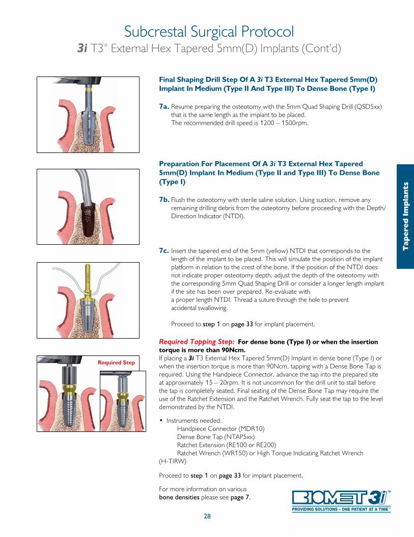
Final Shaping Drill Step Of A 3i T3 External Hex Tapered 5mm(D) Implant In Medium (Type II And Type III) To Dense Bone (Type I)
7a. Resume preparing the osteotomy with the 5mm Quad Shaping Drill (QSD5xx) that is the same length as the implant to be placed. The recommended drill speed is 1200 – 1500rpm.
Preparation For Placement Of A 3i T3 External Hex Tapered 5mm(D) Implant In Medium (Type II and Type III) To Dense Bone (Type I)
7b. Flush the osteotomy with sterile saline solution. Using suction, remove any remaining drilling debris from the osteotomy before proceeding with the Depth/Direction Indicator (NTDI).
7c. Insert the tapered end of the 5mm (yellow) NTDI that corresponds to the length of the implant to be placed. This will simulate the position of the implant platform in relation to the crest of the bone. If the position of the NTDI does not indicate proper osteotomy depth, adjust the depth of the osteotomy with the corresponding 5mm Quad Shaping Drill or consider a longer length implant if the site has been over prepared. Re-evaluate with a proper length NTDI. Thread a suture through the hole to prevent accidental swallowing.
Proceed to step 1 on page 33 for implant placement.
Required Tapping Step: For dense bone (Type I) or when the insertion torque is more than 90Ncm.If placing a 3i T3 External Hex Tapered 5mm(D) Implant in dense bone (Type I) or when the insertion torque is more than 90Ncm, tapping with a Dense Bone Tap is required. Using the Handpiece Connector, advance the tap into the prepared site at approximately 15 – 20rpm. It is not uncommon for the drill unit to stall before the tap is completely seated. Final seating of the Dense Bone Tap may require the use of the Ratchet Extension and the Ratchet Wrench. Fully seat the tap to the level demonstrated by the NTDI.
• Instruments needed: Handpiece Connector (MDR10) Dense Bone Tap (NTAP5xx) Ratchet Extension (RE100 or RE200) Ratchet Wrench (WR150) or High Torque Indicating Ratchet Wrench (H-TIRW) Proceed to step 1 on page 33 for implant placement.
For more information on various bone densities please see page 7.
Required Step
Subcrestal Surgical Protocol3i T3® External Hex Tapered 5mm(D) Implants (Cont’d)
Tap
ered
Im
pla
nts
29
For a quick reference guide to 3i T3 External Hex Tapered 6mm(D) Implant placement, please refer to page 19.
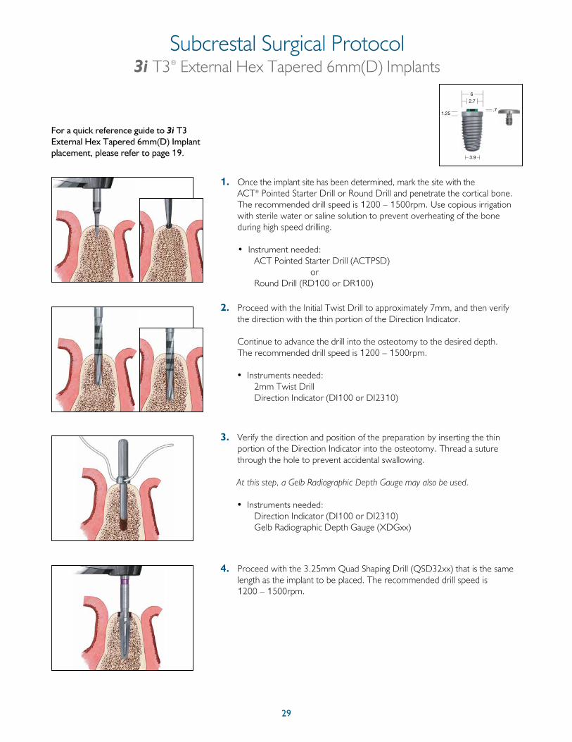
1. Once the implant site has been determined, mark the site with the ACT® Pointed Starter Drill or Round Drill and penetrate the cortical bone. The recommended drill speed is 1200 – 1500rpm. Use copious irrigation with sterile water or saline solution to prevent overheating of the bone during high speed drilling.
• Instrument needed: ACT Pointed Starter Drill (ACTPSD) or Round Drill (RD100 or DR100)
2. Proceed with the Initial Twist Drill to approximately 7mm, and then verify the direction with the thin portion of the Direction Indicator.
Continue to advance the drill into the osteotomy to the desired depth. The recommended drill speed is 1200 – 1500rpm.
• Instruments needed: 2mm Twist Drill Direction Indicator (DI100 or DI2310)
3. Verify the direction and position of the preparation by inserting the thin portion of the Direction Indicator into the osteotomy. Thread a suture through the hole to prevent accidental swallowing.
At this step, a Gelb Radiographic Depth Gauge may also be used.
• Instruments needed: Direction Indicator (DI100 or DI2310) Gelb Radiographic Depth Gauge (XDGxx)
4. Proceed with the 3.25mm Quad Shaping Drill (QSD32xx) that is the same length as the implant to be placed. The recommended drill speed is 1200 – 1500rpm.
Subcrestal Surgical Protocol3i T3® External Hex Tapered 6mm(D) Implants
3.9
1.25
6
2.7
.7
30
Subcrestal Surgical Protocol3i T3® External Hex Tapered 6mm(D) Implants (Cont’d)
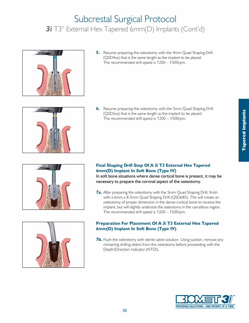
5. Resume preparing the osteotomy with the 4mm Quad Shaping Drill (QSD4xx) that is the same length as the implant to be placed.
The recommended drill speed is 1200 – 1500rpm.
6. Resume preparing the osteotomy with the 5mm Quad Shaping Drill (QSD5xx) that is the same length as the implant to be placed.
The recommended drill speed is 1200 – 1500rpm.
Final Shaping Drill Step Of A 3i T3 External Hex Tapered 6mm(D) Implant In Soft Bone (Type IV)In soft bone situations where dense cortical bone is present, it may be necessary to prepare the coronal aspect of the osteotomy.
7a. After preparing the osteotomy with the 5mm Quad Shaping Drill, finish with a 6mm x 8.5mm Quad Shaping Drill (QSD685). This will create an osteotomy of proper dimension in the dense cortical bone to receive the implant, but will slightly undersize the osteotomy in the cancellous region. The recommended drill speed is 1200 – 1500rpm.
Preparation For Placement Of A 3i T3 External Hex Tapered 6mm(D) Implant In Soft Bone (Type IV)
7b. Flush the osteotomy with sterile saline solution. Using suction, remove any remaining drilling debris from the osteotomy before proceeding with the Depth/Direction Indicator (NTDI).
Tap
ered
Im
pla
nts
31
Subcrestal Surgical Protocol3i T3® External Hex Tapered 6mm(D) Implants (Cont’d)
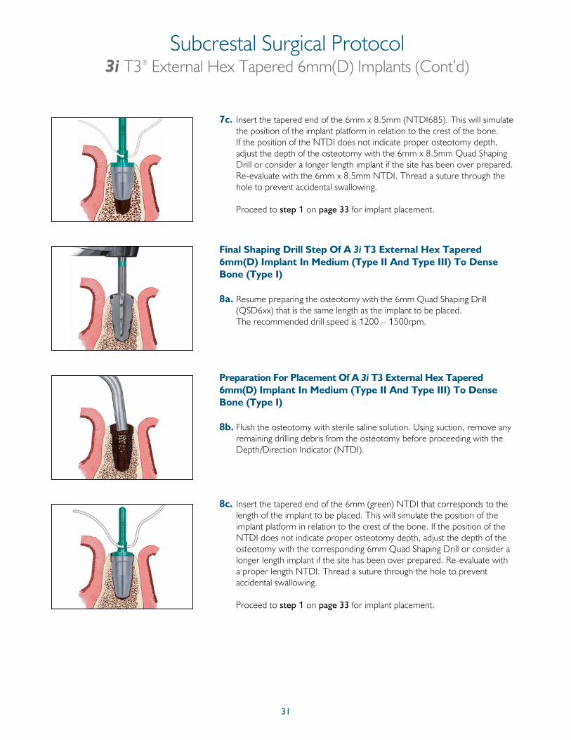
7c. Insert the tapered end of the 6mm x 8.5mm (NTDI685). This will simulate the position of the implant platform in relation to the crest of the bone. If the position of the NTDI does not indicate proper osteotomy depth, adjust the depth of the osteotomy with the 6mm x 8.5mm Quad Shaping Drill or consider a longer length implant if the site has been over prepared. Re-evaluate with the 6mm x 8.5mm NTDI. Thread a suture through the hole to prevent accidental swallowing.
Proceed to step 1 on page 33 for implant placement.
Final Shaping Drill Step Of A 3i T3 External Hex Tapered 6mm(D) Implant In Medium (Type II And Type III) To Dense Bone (Type I)
8a. Resume preparing the osteotomy with the 6mm Quad Shaping Drill (QSD6xx) that is the same length as the implant to be placed.
The recommended drill speed is 1200 – 1500rpm.
Preparation For Placement Of A 3i T3 External Hex Tapered 6mm(D) Implant In Medium (Type II And Type III) To Dense Bone (Type I)
8b. Flush the osteotomy with sterile saline solution. Using suction, remove any remaining drilling debris from the osteotomy before proceeding with the Depth/Direction Indicator (NTDI).
8c. Insert the tapered end of the 6mm (green) NTDI that corresponds to the length of the implant to be placed. This will simulate the position of the implant platform in relation to the crest of the bone. If the position of the NTDI does not indicate proper osteotomy depth, adjust the depth of the osteotomy with the corresponding 6mm Quad Shaping Drill or consider a longer length implant if the site has been over prepared. Re-evaluate with a proper length NTDI. Thread a suture through the hole to prevent accidental swallowing.
Proceed to step 1 on page 33 for implant placement.
32
Tap
ered
Im
pla
nts
Required Step
Subcrestal Surgical Protocol3i T3® External Hex Tapered 6mm(D) Implants (Cont’d)
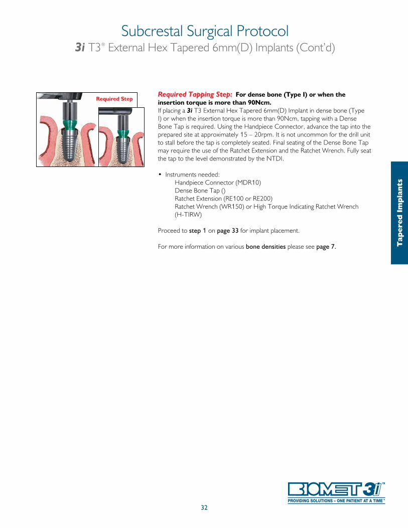
Required Tapping Step: For dense bone (Type I) or when the insertion torque is more than 90Ncm.If placing a 3i T3 External Hex Tapered 6mm(D) Implant in dense bone (Type I) or when the insertion torque is more than 90Ncm, tapping with a Dense Bone Tap is required. Using the Handpiece Connector, advance the tap into the prepared site at approximately 15 – 20rpm. It is not uncommon for the drill unit to stall before the tap is completely seated. Final seating of the Dense Bone Tap may require the use of the Ratchet Extension and the Ratchet Wrench. Fully seat the tap to the level demonstrated by the NTDI.
• Instruments needed: Handpiece Connector (MDR10) Dense Bone Tap () Ratchet Extension (RE100 or RE200) Ratchet Wrench (WR150) or High Torque Indicating Ratchet Wrench (H-TIRW) Proceed to step 1 on page 33 for implant placement.
For more information on various bone densities please see page 7.
33
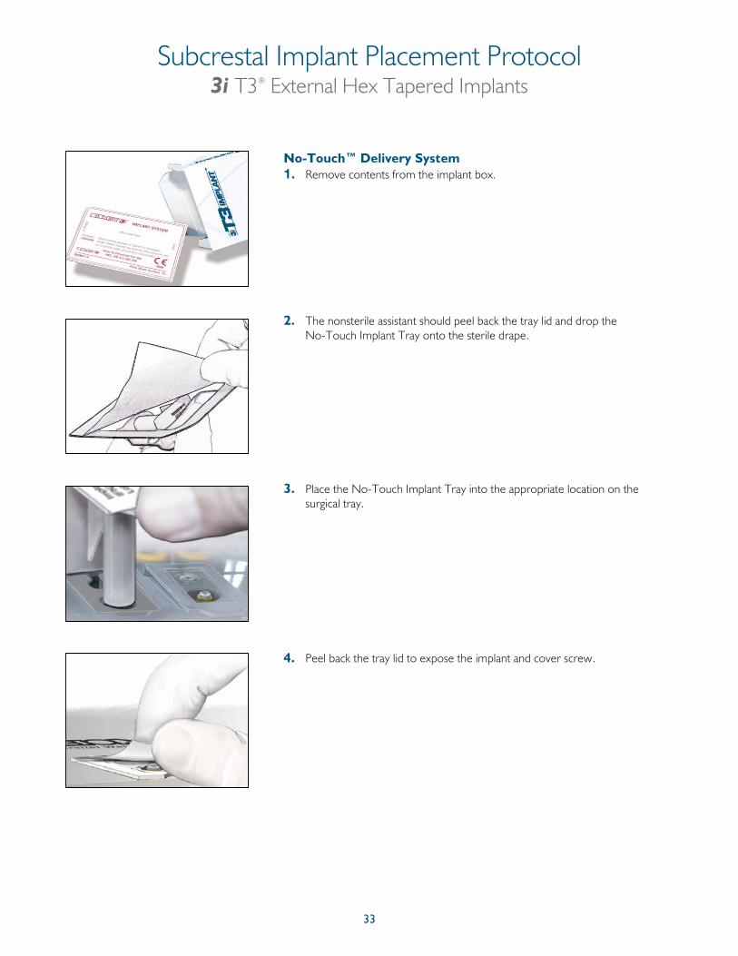
Subcrestal Implant Placement Protocol3i T3® External Hex Tapered Implants
No-Touch™ Delivery System1. Remove contents from the implant box.
2. The nonsterile assistant should peel back the tray lid and drop the No-Touch Implant Tray onto the sterile drape.
3. Place the No-Touch Implant Tray into the appropriate location on the surgical tray.
4. Peel back the tray lid to expose the implant and cover screw.
34
Subcrestal Implant Placement Protocol (Cont’d)3i T3® External Hex Tapered Implants
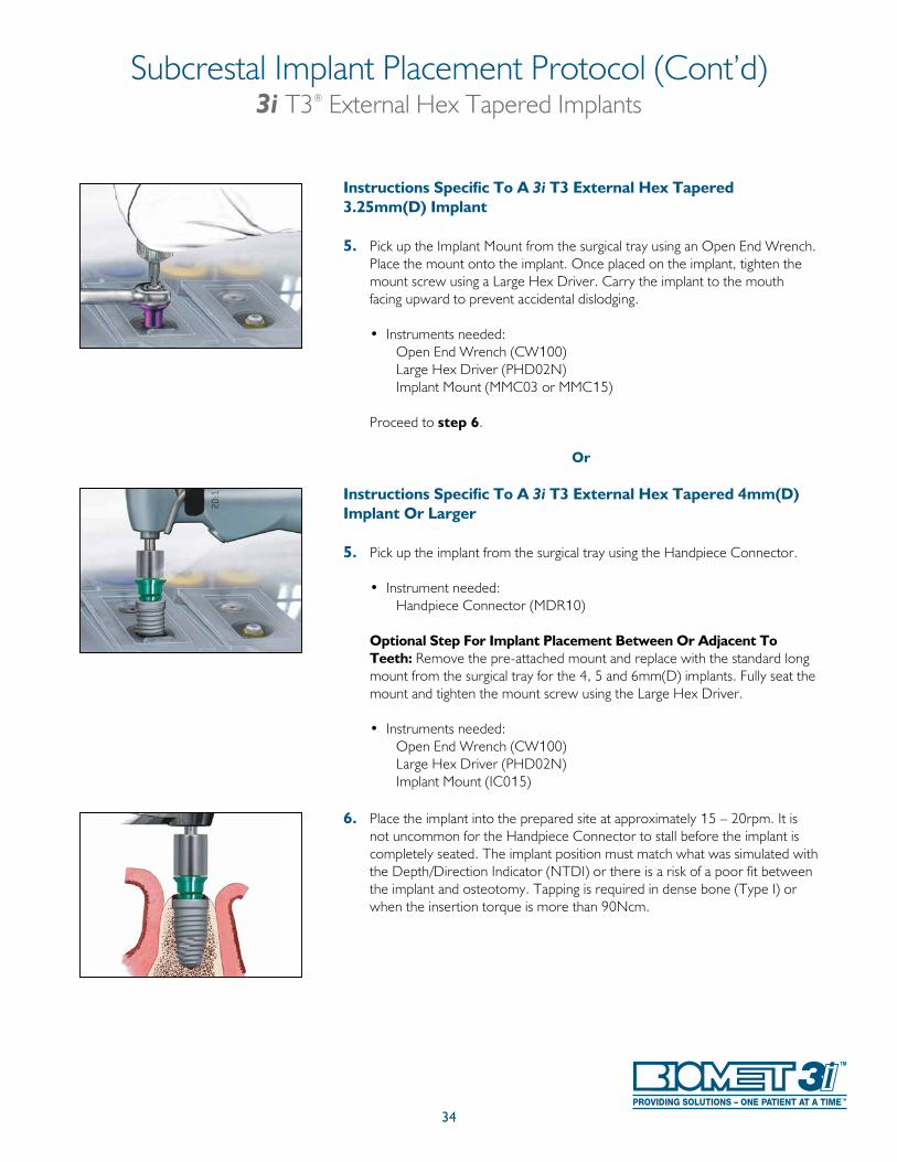
Instructions Specific To A 3i T3 External Hex Tapered 3.25mm(D) Implant
5. Pick up the Implant Mount from the surgical tray using an Open End Wrench. Place the mount onto the implant. Once placed on the implant, tighten the mount screw using a Large Hex Driver. Carry the implant to the mouth facing upward to prevent accidental dislodging.
• Instruments needed: Open End Wrench (CW100) Large Hex Driver (PHD02N) Implant Mount (MMC03 or MMC15)
Proceed to step 6.
Or
Instructions Specific To A 3i T3 External Hex Tapered 4mm(D) Implant Or Larger
5. Pick up the implant from the surgical tray using the Handpiece Connector.
• Instrument needed: Handpiece Connector (MDR10)
Optional Step For Implant Placement Between Or Adjacent To Teeth: Remove the pre-attached mount and replace with the standard long mount from the surgical tray for the 4, 5 and 6mm(D) implants. Fully seat the mount and tighten the mount screw using the Large Hex Driver.
• Instruments needed: Open End Wrench (CW100) Large Hex Driver (PHD02N) Implant Mount (IC015)
6. Place the implant into the prepared site at approximately 15 – 20rpm. It is not uncommon for the Handpiece Connector to stall before the implant is completely seated. The implant position must match what was simulated with the Depth/Direction Indicator (NTDI) or there is a risk of a poor fit between the implant and osteotomy. Tapping is required in dense bone (Type I) or when the insertion torque is more than 90Ncm.
35
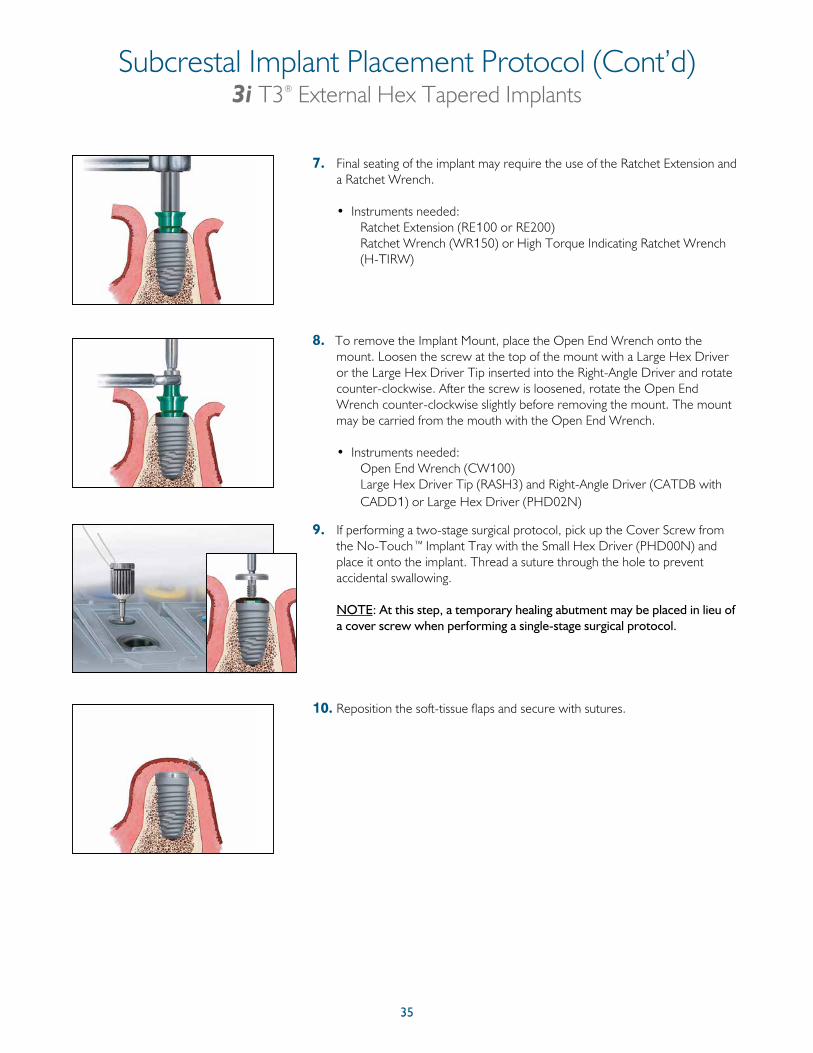
7. Final seating of the implant may require the use of the Ratchet Extension and a Ratchet Wrench.
• Instruments needed: Ratchet Extension (RE100 or RE200) Ratchet Wrench (WR150) or High Torque Indicating Ratchet Wrench
(H-TIRW)
8. To remove the Implant Mount, place the Open End Wrench onto the mount. Loosen the screw at the top of the mount with a Large Hex Driver or the Large Hex Driver Tip inserted into the Right-Angle Driver and rotate counter-clockwise. After the screw is loosened, rotate the Open End Wrench counter-clockwise slightly before removing the mount. The mount may be carried from the mouth with the Open End Wrench.
• Instruments needed: Open End Wrench (CW100) Large Hex Driver Tip (RASH3) and Right-Angle Driver (CATDB with
CADD1) or Large Hex Driver (PHD02N)
9. If performing a two-stage surgical protocol, pick up the Cover Screw from the No-Touch™ Implant Tray with the Small Hex Driver (PHD00N) and place it onto the implant. Thread a suture through the hole to prevent accidental swallowing.
NOTE: At this step, a temporary healing abutment may be placed in lieu of
a cover screw when performing a single-stage surgical protocol.
10. Reposition the soft-tissue flaps and secure with sutures.
Subcrestal Implant Placement Protocol (Cont’d)3i T3® External Hex Tapered Implants
36
* Discrete Crystalline Deposition (DCD) is a process by which the implant surface is treated with a nano-scale deposition of biocompatible calcium phosphate crystals.
External Hex Parallel Walled Implants
3i T3® External Hex 3i T3 with DCD®*External Hex
37
Twist Drill Depth Marking System3i T3® External Hex Parallel Walled Implants
ITD Reusable Drills • Internal irrigation lumen • All thin lines
Types Of Twist Drills
DT & DTN Disposable Drills• Without internal irrigation lumen• Bands• DTN disposable drills do not
have a hub
ACT Drill Marks
The length of the drill tip is not included in the depth mark measurement. The drill tip length should be considered when preparing the osteotomy.
The length of the drill tip varies with the diameter of the drill.
The center of the drill’s single line depth marks and the beginning or end of the broad band indicate subcrestal placement for the corresponding length implant.
Drill Tip Dimensions
8.5mm
7mm
Drill Tip
10mm
11.5mm
13mm
15mm
Max 1.3mm
ACT® Reusable Drills• Without internal irrigation lumen• Alternating lines and bands• No hub
Drill DiameterITD/DTN/DT
Drill Tip LengthACT
Drill Tip Length2mm 0.6mm 0.6mm
2.3mm 0.7mm N/A2.75mm 0.8mm 0.9mm
3mm 0.9mm 0.9mm3.15mm 1mm 1mm3.25mm 1mm 1mm3.85mm N/A 1.2mm4.25mm 0.4mm 1.3mm4.85mm N/A 1.3mm5.25mm 0.5mm 1.2mm
A 2mm Twist Drill is used to prepare the osteotomy for the sequential twist drills in each of the parallel walled surgical protocols. Pages 37-40 outline the guidelines for understanding the depth markings on the Twist Drill System.
38
Twist Drill Depth Marking System (Cont’d)3i T3® External Hex Parallel Walled Implants
The Depth Marks measurement system provides a mark on the drill that corresponds to the placement of the implant via well-established procedures. The BIOMET 3i original protocol follows the principles of protecting the implant from premature loading by placing the implant subcrestally.
Drilling DepthThe drilling depth with the Twist Drill will vary depending on the type of placement related to the bone crest.
The depth marks are specific for subcrestal implant placement only. There are no specific depth marks on the drills for crestal or supracrestal placement.
The drill depth marks do not indicate implant lengths. Rather, the drill depth marks represent the length of the implant with a standard 1mm cover screw in place. As a result, to place an implant and cover screw subcrestally requires drilling to the middle of the single line depth mark or the beginning or end of the broad band depth mark on ACT® Drills. For crestal placement, drill halfway before the corresponding depth mark for the implant length. For supracrestal placement, the drill depth mark should remain above the bone by 1mm for the cover screw plus the implant collar height. Please refer to the diagram at the bottom of page 39 for more information on supracrestal placement.
2mmTwist Drill
Depth Gauge Implant With A1mm Cover Screw
Standard Subcrestal Protocol -1mm Cover Screw
Drill TipMax 1.3mm
SubcrestalCrestal Supracrestal
Drilling Depth Comparison
11.5mm(L) 3i T3External Hex Implant
L = Length
Par
alle
l Wal
led
Impl
ants
L = LengthLabeled vs. Actual Lengths
Drill TipMax 1.3mm
The center of the drill’s single line depth marks and the beginning or end of the broad band indicate the length of the implant with a standard 1mm cover screw in place.
The actual implant lengths from the top of the implant collar (platform) to the tip of the implant are shorter by 0.4mm than the labeled length.
The landmarks (grooves) on the external hex implant mount act as a reference during implant placement.
11.5mm(L) 3i T3 External Hex Implant
15mm
LabeledLengths
Actual Implant Lengths With Full Cover Screw ON
15mm
13mm
11.5mm
10mm
8.5mm
7mm
13mm
11.5mm
10mm
8.5mm
7mm
SubcrestalCrestal
Supplied Cover Screw
39
Twist Drill Depth Marking System (Cont’d)3i T3® External Hex Parallel Walled Implants
Subcrestal Placement
• The implant platform will be 1mm (or more) below the bone crest.• Mostly used in the anterior region for aesthetics.
8.5mm7mm
Subcrestal
10mm1mm
Bone Crest For subcrestal implant placement, drill to the drill depth mark that corresponds to the labeled implant length.
11.5mm
Drill TipMax 1.3mm
11.5mm(L) 3i T3 External Hex Implant
Crestal Placement
• The implant platform will be at the bone crest.
For crestal implant placement, stop drilling 1mm before the drill depth mark that corresponds to the labeled implant length (1mm equals the traditional cover screw height).
Drill TipMax 1.3mm
8.5mm7mm
Crestal
10mm1mmBone Crest11.5mm
11.5mm(L) 3i T3 External Hex Implant
Supracrestal Placement
• The implant collar will be above the bone crest. For supracrestal implant placement, stop drilling 2.25mm before the drill depth mark that corresponds to the labeled implant length (2.25mm equals the 1mm traditional cover screw height plus the 1.25mm implant collar height).
NOTE: A Countersink Drill is not needed for external connection supracrestal implant placement.
Drill TipMax 1.3mm
8.5mm7mm
Supracrestal
10mm 1.25mm Collar Height
Bone Crest
11.5mm
11.5mm(L) 3i T3 External Hex Implant
L = Length
40
Twist Drill Depth Marking System (Cont’d)3i T3® External Hex Parallel Walled Implants
Par
alle
l Wal
led
Impl
ants
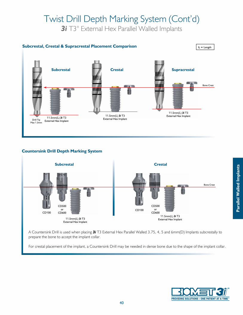
Countersink Drill Depth Marking System
A Countersink Drill is used when placing 3i T3 External Hex Parallel Walled 3.75, 4, 5 and 6mm(D) Implants subcrestally to prepare the bone to accept the implant collar.
For crestal placement of the implant, a Countersink Drill may be needed in dense bone due to the shape of the implant collar.
CD500or
CD600
CD500or
CD600
Bone Crest
Subcrestal Crestal
CD100CD100
11.5mm(L) 3i T3 External Hex Implant
11.5mm(L) 3i T3 External Hex Implant
L = Length
Subcrestal Crestal
Subcrestal, Crestal & Supracrestal Placement Comparison
Bone Crest
Supracrestal
Drill TipMax 1.3mm
11.5mm(L) 3i T3 External Hex Implant
11.5mm(L) 3i T3 External Hex Implant
11.5mm(L) 3i T3 External Hex Implant
41
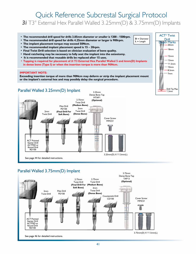
Quick Reference Subcrestal Surgical Protocol3i T3® External Hex Parallel Walled 3.25mm(D) & 3.75mm(D) Implants
20mm
18mm
15mm
13mm
11.5mm10mm8.5mm7mm
ACT® Twist Drill
Depth Marks
Drill Tip Max 1.3mm
• The recommended drill speed for drills 3.85mm diameter or smaller is 1200 – 1500rpm.• The recommended drill speed for drills 4.25mm diameter or larger is 900rpm.• The implant placement torque may exceed 50Ncm.• The recommended implant placement speed is 15 – 20rpm.• Final Twist Drill selection is based on clinician evaluation of bone quality.• Hand ratcheting may be necessary to fully seat the implant into the osteotomy.• It is recommended that reusable drills be replaced after 15 uses.• Tapping is required for placement of 3i T3 External Hex Parallel Walled 5 and 6mm(D) Implants
in dense bone (Type I) or when the insertion torque is more than 90Ncm.
D = DiameterL = Length
IMPORTANT NOTE: Exceeding insertion torque of more than 90Ncm may deform or strip the implant placement mount or the implant’s external hex and may possibly delay the surgical procedure.
Parallel Walled 3.25mm(D) Implant
3.25mm(D) X 11.5mm(L)
ACT Pointed Starter DrillACTPSD or Round Drill
RD100
2mmTwist Drill
Pilot DrillPD100
(Final Drill For Soft Bone)
2.75mmTwist Drill
(Medium Bone)3mm
Twist Drill(Dense Bone)
3.25mmDense Bone Tap
MTAP1(Optional)
Cover ScrewMMCS1
See page 44 for detailed instructions.
Parallel Walled 3.75mm(D) Implant
ACT Pointed Starter DrillACTPSD or Round Drill
RD100
2mmTwist Drill
Pilot DrillPD100
2.75mmTwist Drill
(Medium Bone)3mm
Twist Drill(Dense Bone)
3.75mm(D) X 11.5mm(L)
3.75mmDense Bone Tap
TAP13(Optional)
Cover ScrewMMCS1
Countersink DrillCD100
See page 46 for detailed instructions.
2.75mmTwist Drill
(Final Drill ForSoft Bone)
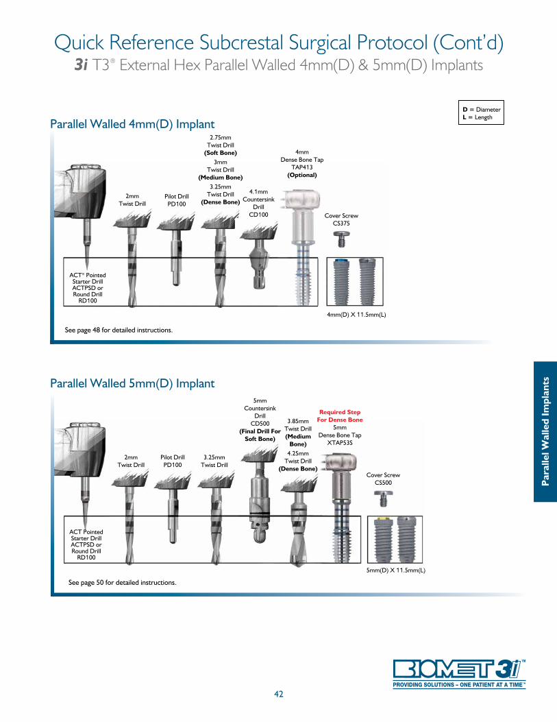
42
Quick Reference Subcrestal Surgical Protocol (Cont’d)3i T3® External Hex Parallel Walled 4mm(D) & 5mm(D) Implants
D = DiameterL = Length
See page 48 for detailed instructions.
Parallel Walled 4mm(D) Implant
2mmTwist Drill
Pilot DrillPD100
2.75mmTwist Drill
(Soft Bone)3mm
Twist Drill(Medium Bone)
3.25mm Twist Drill
(Dense Bone)
4.1mmCountersink
DrillCD100
4mm(D) X 11.5mm(L)
4mmDense Bone Tap
TAP413(Optional)
Cover ScrewCS375
ACT® Pointed Starter DrillACTPSD or Round Drill
RD100
Par
alle
l Wal
led
Impl
ants
See page 50 for detailed instructions.
5mm(D) X 11.5mm(L)
2mmTwist Drill
Pilot DrillPD100
5mmCountersink
DrillCD500
(Final Drill For Soft Bone)
3.85mmTwist Drill(Medium
Bone)4.25mm
Twist Drill(Dense Bone)
3.25mm Twist Drill
ACT Pointed Starter DrillACTPSD or Round Drill
RD100
Cover ScrewCS500
Required Step For Dense Bone
5mmDense Bone Tap
XTAP53S
Parallel Walled 5mm(D) Implant
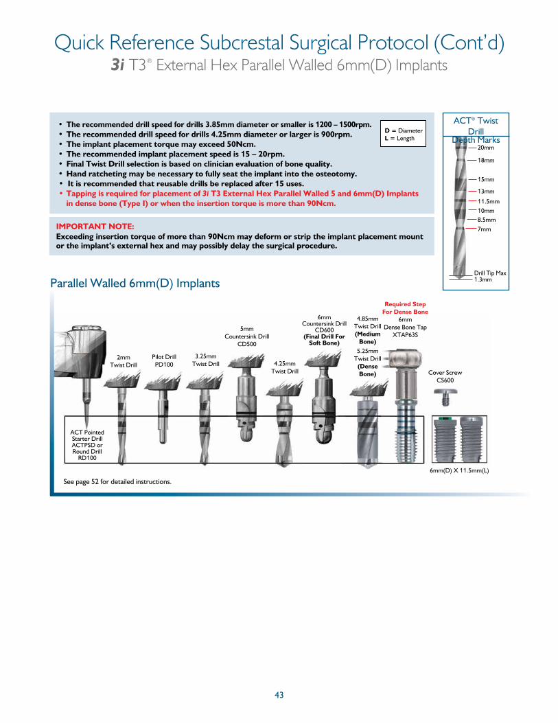
43
Quick Reference Subcrestal Surgical Protocol (Cont’d)3i T3® External Hex Parallel Walled 6mm(D) Implants
See page 52 for detailed instructions.
Parallel Walled 6mm(D) Implants
2mmTwist Drill
Pilot DrillPD100
5mmCountersink Drill
CD500
6mmCountersink Drill
CD600 (Final Drill For
Soft Bone)
3.25mm Twist Drill
4.85mm Twist Drill(Medium
Bone)5.25mm
Twist Drill(Dense Bone)
6mm(D) X 11.5mm(L)
ACT Pointed Starter DrillACTPSD or Round Drill
RD100
4.25mmTwist Drill Cover Screw
CS600
Required Step For Dense Bone
6mmDense Bone Tap
XTAP63S
20mm
18mm
15mm
13mm
11.5mm10mm8.5mm7mm
ACT® Twist Drill
Depth Marks
Drill Tip Max 1.3mm
• The recommended drill speed for drills 3.85mm diameter or smaller is 1200 – 1500rpm.• The recommended drill speed for drills 4.25mm diameter or larger is 900rpm.• The implant placement torque may exceed 50Ncm.• The recommended implant placement speed is 15 – 20rpm.• Final Twist Drill selection is based on clinician evaluation of bone quality.• Hand ratcheting may be necessary to fully seat the implant into the osteotomy.• It is recommended that reusable drills be replaced after 15 uses.• Tapping is required for placement of 3i T3 External Hex Parallel Walled 5 and 6mm(D) Implants
in dense bone (Type I) or when the insertion torque is more than 90Ncm.
D = DiameterL = Length
IMPORTANT NOTE: Exceeding insertion torque of more than 90Ncm may deform or strip the implant placement mount or the implant’s external hex and may possibly delay the surgical procedure.
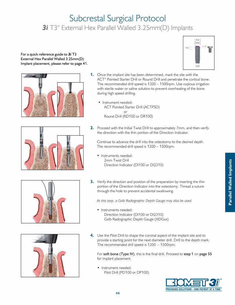
1. Once the implant site has been determined, mark the site with the ACT® Pointed Starter Drill or Round Drill and penetrate the cortical bone. The recommended drill speed is 1200 – 1500rpm. Use copious irrigation with sterile water or saline solution to prevent overheating of the bone during high speed drilling.
• Instrument needed: ACT Pointed Starter Drill (ACTPSD) or Round Drill (RD100 or DR100)
2. Proceed with the Initial Twist Drill to approximately 7mm, and then verify the direction with the thin portion of the Direction Indicator.
Continue to advance the drill into the osteotomy to the desired depth. The recommended drill speed is 1200 – 1500rpm. • Instruments needed: 2mm Twist Drill
Direction Indicator (DI100 or DI2310)
3. Verify the direction and position of the preparation by inserting the thin portion of the Direction Indicator into the osteotomy. Thread a suture through the hole to prevent accidental swallowing.
At this step, a Gelb Radiographic Depth Gauge may also be used.
• Instruments needed: Direction Indicator (DI100 or DI2310) Gelb Radiographic Depth Gauge (XDGxx)
4. Use the Pilot Drill to shape the coronal aspect of the implant site and to provide a starting point for the next diameter drill. Drill to the depth mark. The recommended drill speed is 1200 – 1500rpm.
For soft bone (Type IV), this is the final drill. Proceed to step 1 on page 55
for implant placement. • Instrument needed: Pilot Drill (PD100 or DP100)
44
Subcrestal Surgical Protocol3i T3® External Hex Parallel Walled 3.25mm(D) Implants
For a quick reference guide to 3i T3 External Hex Parallel Walled 3.25mm(D) Implant placement, please refer to page 41.
Par
alle
l Wal
led
Impl
ants
1.5
2.4
3.4
2.5
.7
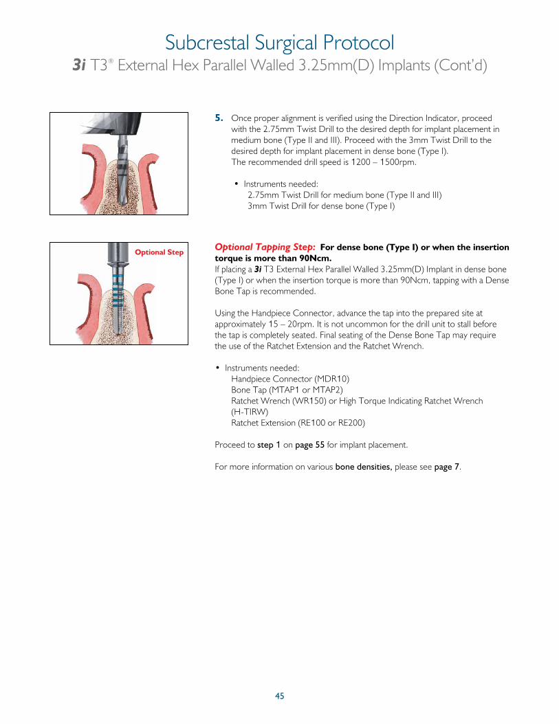
45
5. Once proper alignment is verified using the Direction Indicator, proceed with the 2.75mm Twist Drill to the desired depth for implant placement in medium bone (Type II and III). Proceed with the 3mm Twist Drill to the desired depth for implant placement in dense bone (Type I). The recommended drill speed is 1200 – 1500rpm.
• Instruments needed: 2.75mm Twist Drill for medium bone (Type II and III) 3mm Twist Drill for dense bone (Type I)
Optional Tapping Step: For dense bone (Type I) or when the insertion torque is more than 90Ncm.If placing a 3i T3 External Hex Parallel Walled 3.25mm(D) Implant in dense bone (Type I) or when the insertion torque is more than 90Ncm, tapping with a Dense Bone Tap is recommended.
Using the Handpiece Connector, advance the tap into the prepared site at approximately 15 – 20rpm. It is not uncommon for the drill unit to stall before the tap is completely seated. Final seating of the Dense Bone Tap may require the use of the Ratchet Extension and the Ratchet Wrench.
• Instruments needed: Handpiece Connector (MDR10) Bone Tap (MTAP1 or MTAP2) Ratchet Wrench (WR150) or High Torque Indicating Ratchet Wrench
(H-TIRW) Ratchet Extension (RE100 or RE200)
Proceed to step 1 on page 55 for implant placement.
For more information on various bone densities, please see page 7.
Optional Step
Subcrestal Surgical Protocol3i T3® External Hex Parallel Walled 3.25mm(D) Implants (Cont’d)
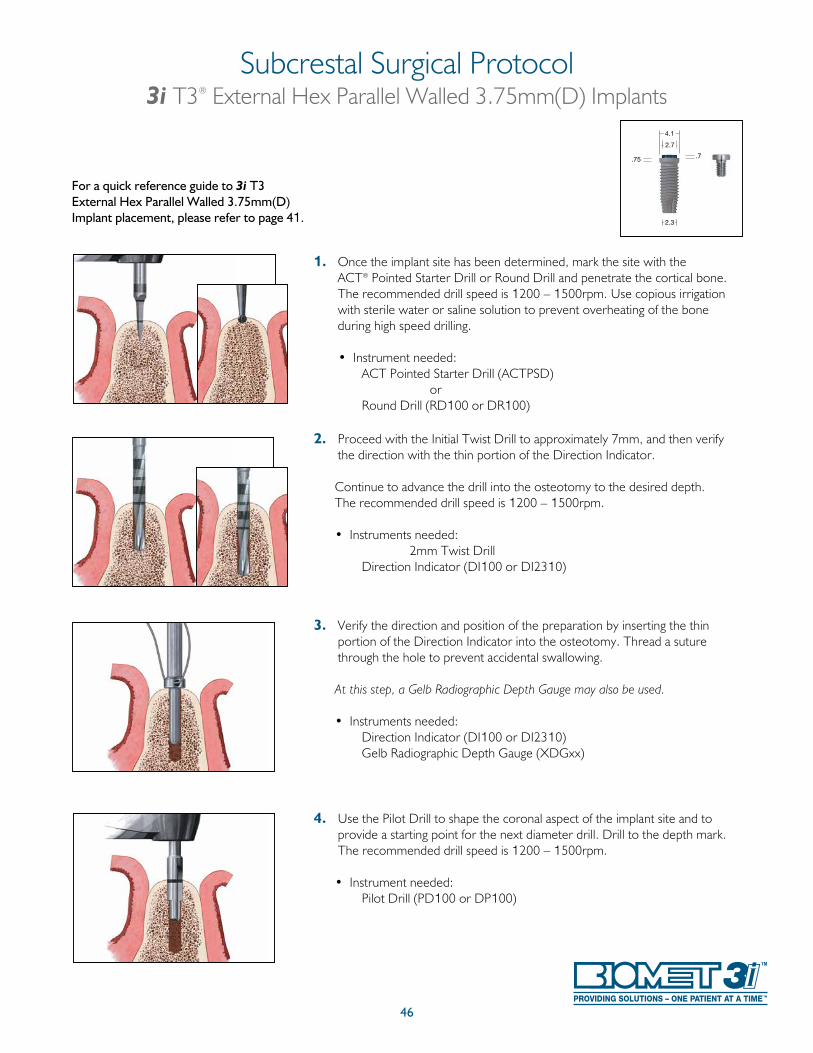
46
1. Once the implant site has been determined, mark the site with the ACT® Pointed Starter Drill or Round Drill and penetrate the cortical bone. The recommended drill speed is 1200 – 1500rpm. Use copious irrigation with sterile water or saline solution to prevent overheating of the bone during high speed drilling.
• Instrument needed: ACT Pointed Starter Drill (ACTPSD) or Round Drill (RD100 or DR100)
2. Proceed with the Initial Twist Drill to approximately 7mm, and then verify the direction with the thin portion of the Direction Indicator.
Continue to advance the drill into the osteotomy to the desired depth. The recommended drill speed is 1200 – 1500rpm. • Instruments needed: 2mm Twist Drill
Direction Indicator (DI100 or DI2310)
3. Verify the direction and position of the preparation by inserting the thin portion of the Direction Indicator into the osteotomy. Thread a suture through the hole to prevent accidental swallowing.
At this step, a Gelb Radiographic Depth Gauge may also be used.
• Instruments needed: Direction Indicator (DI100 or DI2310) Gelb Radiographic Depth Gauge (XDGxx)
4. Use the Pilot Drill to shape the coronal aspect of the implant site and to provide a starting point for the next diameter drill. Drill to the depth mark. The recommended drill speed is 1200 – 1500rpm.
• Instrument needed: Pilot Drill (PD100 or DP100)
Subcrestal Surgical Protocol3i T3® External Hex Parallel Walled 3.75mm(D) Implants
For a quick reference guide to 3i T3 External Hex Parallel Walled 3.75mm(D) Implant placement, please refer to page 41.
.75
4.1
2.3
.7
2.7
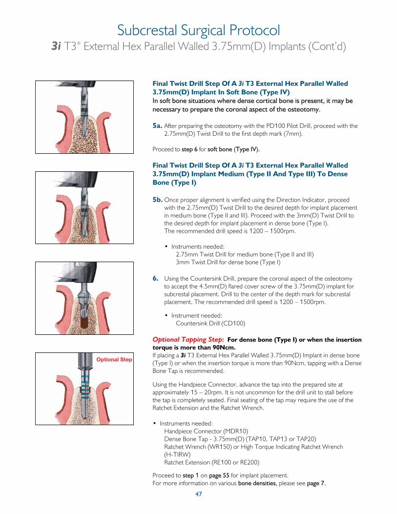
47
Final Twist Drill Step Of A 3i T3 External Hex Parallel Walled 3.75mm(D) Implant In Soft Bone (Type IV)In soft bone situations where dense cortical bone is present, it may be necessary to prepare the coronal aspect of the osteotomy.
5a. After preparing the osteotomy with the PD100 Pilot Drill, proceed with the 2.75mm(D) Twist Drill to the first depth mark (7mm).
Proceed to step 6 for soft bone (Type IV).
Final Twist Drill Step Of A 3i T3 External Hex Parallel Walled 3.75mm(D) Implant Medium (Type II And Type III) To Dense Bone (Type I)
5b. Once proper alignment is verified using the Direction Indicator, proceed with the 2.75mm(D) Twist Drill to the desired depth for implant placement in medium bone (Type II and III). Proceed with the 3mm(D) Twist Drill to the desired depth for implant placement in dense bone (Type I). The recommended drill speed is 1200 – 1500rpm.
• Instruments needed: 2.75mm Twist Drill for medium bone (Type II and III)
3mm Twist Drill for dense bone (Type I) 6. Using the Countersink Drill, prepare the coronal aspect of the osteotomy
to accept the 4.5mm(D) flared cover screw of the 3.75mm(D) implant for subcrestal placement. Drill to the center of the depth mark for subcrestal placement. The recommended drill speed is 1200 – 1500rpm.
• Instrument needed: Countersink Drill (CD100)
Optional Tapping Step: For dense bone (Type I) or when the insertion torque is more than 90Ncm.If placing a 3i T3 External Hex Parallel Walled 3.75mm(D) Implant in dense bone (Type I) or when the insertion torque is more than 90Ncm, tapping with a Dense Bone Tap is recommended.
Using the Handpiece Connector, advance the tap into the prepared site at approximately 15 – 20rpm. It is not uncommon for the drill unit to stall before the tap is completely seated. Final seating of the tap may require the use of the Ratchet Extension and the Ratchet Wrench.
• Instruments needed: Handpiece Connector (MDR10) Dense Bone Tap - 3.75mm(D) (TAP10, TAP13 or TAP20) Ratchet Wrench (WR150) or High Torque Indicating Ratchet Wrench
(H-TIRW) Ratchet Extension (RE100 or RE200)
Proceed to step 1 on page 55 for implant placement.For more information on various bone densities, please see page 7.
Optional Step
Subcrestal Surgical Protocol3i T3® External Hex Parallel Walled 3.75mm(D) Implants (Cont’d)
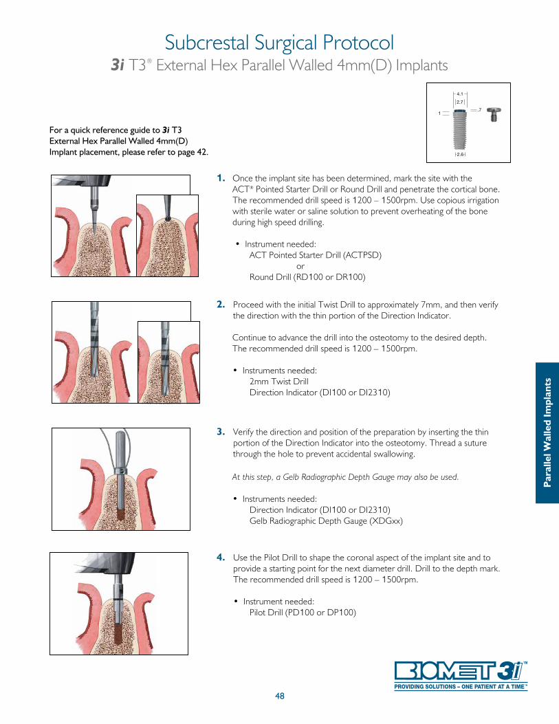
1. Once the implant site has been determined, mark the site with the ACT® Pointed Starter Drill or Round Drill and penetrate the cortical bone. The recommended drill speed is 1200 – 1500rpm. Use copious irrigation with sterile water or saline solution to prevent overheating of the bone during high speed drilling.
• Instrument needed: ACT Pointed Starter Drill (ACTPSD) or Round Drill (RD100 or DR100)
2. Proceed with the initial Twist Drill to approximately 7mm, and then verify the direction with the thin portion of the Direction Indicator.
Continue to advance the drill into the osteotomy to the desired depth. The recommended drill speed is 1200 – 1500rpm.
• Instruments needed: 2mm Twist Drill
Direction Indicator (DI100 or DI2310)
3. Verify the direction and position of the preparation by inserting the thin portion of the Direction Indicator into the osteotomy. Thread a suture through the hole to prevent accidental swallowing.
At this step, a Gelb Radiographic Depth Gauge may also be used.
• Instruments needed: Direction Indicator (DI100 or DI2310) Gelb Radiographic Depth Gauge (XDGxx)
4. Use the Pilot Drill to shape the coronal aspect of the implant site and to provide a starting point for the next diameter drill. Drill to the depth mark. The recommended drill speed is 1200 – 1500rpm.
• Instrument needed: Pilot Drill (PD100 or DP100)
48
Subcrestal Surgical Protocol3i T3® External Hex Parallel Walled 4mm(D) Implants
For a quick reference guide to 3i T3 External Hex Parallel Walled 4mm(D) Implant placement, please refer to page 42.
Par
alle
l Wal
led
Impl
ants
1
2.6
4.1
2.7
.7
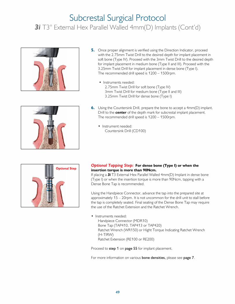
49
5. Once proper alignment is verified using the Direction Indicator, proceed with the 2.75mm Twist Drill to the desired depth for implant placement in soft bone (Type IV). Proceed with the 3mm Twist Drill to the desired depth for implant placement in medium bone (Type II and III). Proceed with the 3.25mm Twist Drill for implant placement in dense bone (Type I). The recommended drill speed is 1200 – 1500rpm.
• Instruments needed: 2.75mm Twist Drill for soft bone (Type IV) 3mm Twist Drill for medium bone (Type II and III) 3.25mm Twist Drill for dense bone (Type I)
6. Using the Countersink Drill, prepare the bone to accept a 4mm(D) implant. Drill to the center of the depth mark for subcrestal implant placement. The recommended drill speed is 1200 – 1500rpm.
• Instrument needed: Countersink Drill (CD100)
Optional Tapping Step: For dense bone (Type I) or when the insertion torque is more than 90Ncm.If placing a 3i T3 External Hex Parallel Walled 4mm(D) Implant in dense bone (Type I) or when the insertion torque is more than 90Ncm, tapping with a Dense Bone Tap is recommended.
Using the Handpiece Connector, advance the tap into the prepared site at approximately 15 – 20rpm. It is not uncommon for the drill unit to stall before the tap is completely seated. Final seating of the Dense Bone Tap may require the use of the Ratchet Extension and the Ratchet Wrench.
• Instruments needed: Handpiece Connector (MDR10) Bone Tap (TAP410, TAP413 or TAP420) Ratchet Wrench (WR150) or Hight Torque Indicating Ratchet Wrench
(H-TIRW) Ratchet Extension (RE100 or RE200)
Proceed to step 1 on page 55 for implant placement.
For more information on various bone densities, please see page 7.
Optional Step
Subcrestal Surgical Protocol3i T3® External Hex Parallel Walled 4mm(D) Implants (Cont’d)
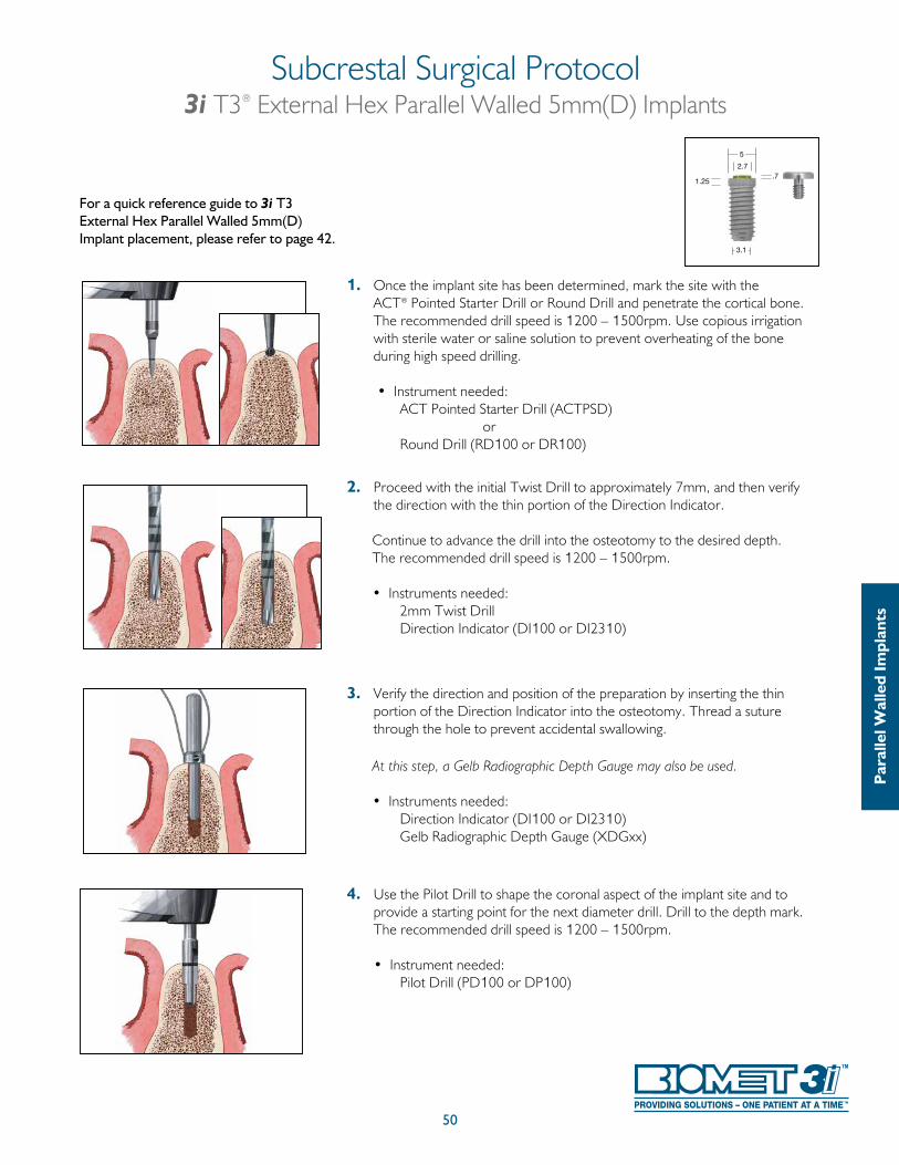
1. Once the implant site has been determined, mark the site with the ACT® Pointed Starter Drill or Round Drill and penetrate the cortical bone. The recommended drill speed is 1200 – 1500rpm. Use copious irrigation with sterile water or saline solution to prevent overheating of the bone during high speed drilling.
• Instrument needed: ACT Pointed Starter Drill (ACTPSD) or Round Drill (RD100 or DR100)
2. Proceed with the initial Twist Drill to approximately 7mm, and then verify the direction with the thin portion of the Direction Indicator.
Continue to advance the drill into the osteotomy to the desired depth. The recommended drill speed is 1200 – 1500rpm. • Instruments needed: 2mm Twist Drill
Direction Indicator (DI100 or DI2310)
3. Verify the direction and position of the preparation by inserting the thin portion of the Direction Indicator into the osteotomy. Thread a suture through the hole to prevent accidental swallowing.
At this step, a Gelb Radiographic Depth Gauge may also be used.
• Instruments needed: Direction Indicator (DI100 or DI2310) Gelb Radiographic Depth Gauge (XDGxx)
4. Use the Pilot Drill to shape the coronal aspect of the implant site and to provide a starting point for the next diameter drill. Drill to the depth mark. The recommended drill speed is 1200 – 1500rpm.
• Instrument needed: Pilot Drill (PD100 or DP100)
Subcrestal Surgical Protocol3i T3® External Hex Parallel Walled 5mm(D) Implants
50
For a quick reference guide to 3i T3 External Hex Parallel Walled 5mm(D) Implant placement, please refer to page 42.
Par
alle
l Wal
led
Impl
ants
5
3.1
2.7.7
1.25
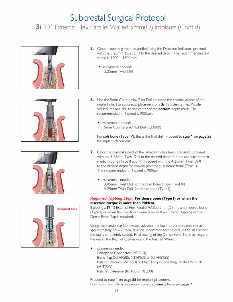
51
Subcrestal Surgical Protocol3i T3® External Hex Parallel Walled 5mm(D) Implants (Cont’d)
5. Once proper alignment is verified using the Direction Indicator, proceed with the 3.25mm Twist Drill to the desired depth. The recommended drill speed is 1200 – 1500rpm.
• Instrument needed: 3.25mm Twist Drill
6. Use the 5mm Countersink/Pilot Drill to shape the coronal aspect of the implant site. For subcrestal placement of a 3i T3 External Hex Parallel Walled Implant, drill to the center of the bottom depth mark. The recommended drill speed is 900rpm.
• Instrument needed: 5mm Countersink/Pilot Drill (CD500)
For soft bone (Type IV), this is the final drill. Proceed to step 1 on page 55 for implant placement.
7. Once the coronal aspect of the osteotomy has been prepared, proceed with the 3.85mm Twist Drill to the desired depth for implant placement in medium bone (Type II and III). Proceed with the 4.25mm Twist Drill to the desired depth for implant placement in dense bone (Type I). The recommended drill speed is 900rpm.
• Instruments needed: 3.85mm Twist Drill for medium bone (Type II and III) 4.25mm Twist Drill for dense bone (Type I)
Required Tapping Step: For dense bone (Type I) or when the insertion torque is more than 90Ncm.If placing a 3i T3 External Hex Parallel Walled 5mm(D) Implant in dense bone (Type I) or when the insertion torque is more than 90Ncm, tapping with a Dense Bone Tap is required.
Using the Handpiece Connector, advance the tap into the prepared site at approximately 15 – 20rpm. It is not uncommon for the drill unit to stall before the tap is completely seated. Final seating of the Dense Bone Tap may require the use of the Ratchet Extension and the Ratchet Wrench.
• Instruments needed: Handpiece Connector (MDR10) Bone Tap (XTAP58S, XTAP53S or XTAP518S) Ratchet Wrench (WR150) or High Torque Indicating Ratchet Wrench
(H-TIRW) Ratchet Extension (RE100 or RE200)
Proceed to step 1 on page 55 for implant placement.For more information on various bone densities, please see page 7.
Required Step
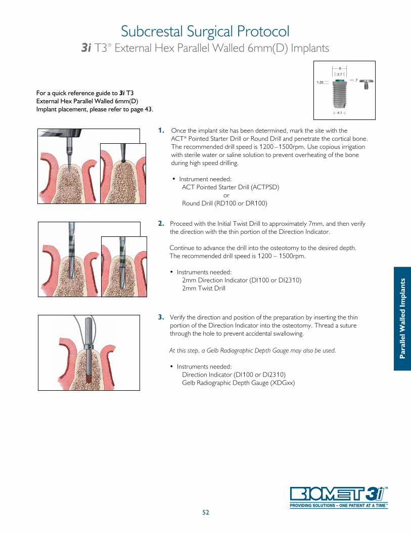
52
1. Once the implant site has been determined, mark the site with the ACT® Pointed Starter Drill or Round Drill and penetrate the cortical bone. The recommended drill speed is 1200 –1500rpm. Use copious irrigation with sterile water or saline solution to prevent overheating of the bone during high speed drilling.
• Instrument needed: ACT Pointed Starter Drill (ACTPSD) or Round Drill (RD100 or DR100)
2. Proceed with the Initial Twist Drill to approximately 7mm, and then verify the direction with the thin portion of the Direction Indicator.
Continue to advance the drill into the osteotomy to the desired depth. The recommended drill speed is 1200 – 1500rpm. • Instruments needed: 2mm Direction Indicator (DI100 or DI2310) 2mm Twist Drill
3. Verify the direction and position of the preparation by inserting the thin portion of the Direction Indicator into the osteotomy. Thread a suture through the hole to prevent accidental swallowing.
At this step, a Gelb Radiographic Depth Gauge may also be used.
• Instruments needed: Direction Indicator (DI100 or DI2310) Gelb Radiographic Depth Gauge (XDGxx)
Subcrestal Surgical Protocol3i T3® External Hex Parallel Walled 6mm(D) Implants
For a quick reference guide to 3i T3 External Hex Parallel Walled 6mm(D) Implant placement, please refer to page 43.
Par
alle
l Wal
led
Impl
ants
4.1
6
1.25
2.7
.7
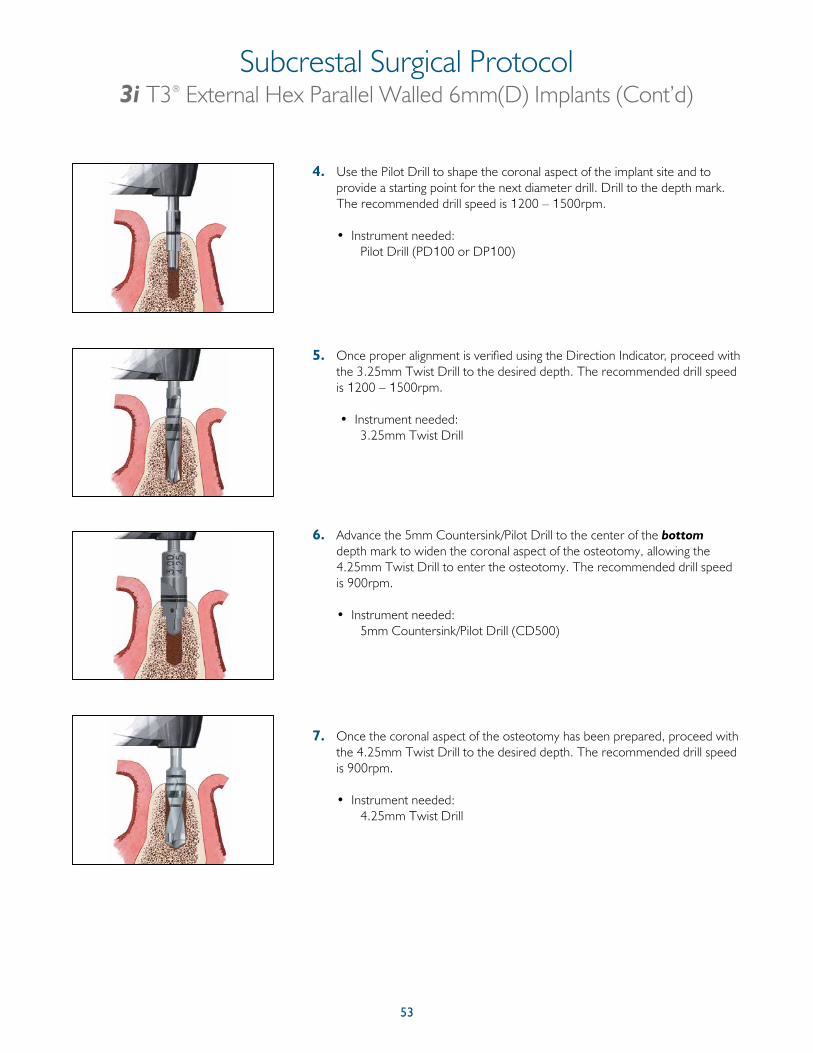
53
4. Use the Pilot Drill to shape the coronal aspect of the implant site and to provide a starting point for the next diameter drill. Drill to the depth mark. The recommended drill speed is 1200 – 1500rpm.
• Instrument needed: Pilot Drill (PD100 or DP100)
5. Once proper alignment is verified using the Direction Indicator, proceed with the 3.25mm Twist Drill to the desired depth. The recommended drill speed is 1200 – 1500rpm.
• Instrument needed: 3.25mm Twist Drill
6. Advance the 5mm Countersink/Pilot Drill to the center of the bottom depth mark to widen the coronal aspect of the osteotomy, allowing the 4.25mm Twist Drill to enter the osteotomy. The recommended drill speed is 900rpm.
• Instrument needed: 5mm Countersink/Pilot Drill (CD500)
7. Once the coronal aspect of the osteotomy has been prepared, proceed with the 4.25mm Twist Drill to the desired depth. The recommended drill speed is 900rpm.
• Instrument needed: 4.25mm Twist Drill
Subcrestal Surgical Protocol3i T3® External Hex Parallel Walled 6mm(D) Implants (Cont’d)
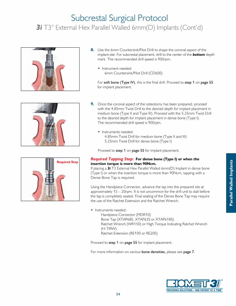
54
8. Use the 6mm Countersink/Pilot Drill to shape the coronal aspect of the implant site. For subcrestal placement, drill to the center of the bottom depth mark. The recommended drill speed is 900rpm.
• Instrument needed: 6mm Countersink/Pilot Drill (CD600)
For soft bone (Type IV), this is the final drill. Proceed to step 1 on page 55 for implant placement.
9. Once the coronal aspect of the osteotomy has been prepared, proceed with the 4.85mm Twist Drill to the desired depth for implant placement in medium bone (Type II and Type III). Proceed with the 5.25mm Twist Drill to the desired depth for implant placement in dense bone (Type I). The recommended drill speed is 900rpm.
• Instruments needed: 4.85mm Twist Drill for medium bone (Type II and III) 5.25mm Twist Drill for dense bone (Type I)
Proceed to step 1 on page 55 for implant placement.
Required Tapping Step: For dense bone (Type I) or when the insertion torque is more than 90Ncm.If placing a 3i T3 External Hex Parallel Walled 6mm(D) Implant in dense bone (Type I) or when the insertion torque is more than 90Ncm, tapping with a Dense Bone Tap is required.
Using the Handpiece Connector, advance the tap into the prepared site at approximately 15 – 20rpm. It is not uncommon for the drill unit to stall before the tap is completely seated. Final seating of the Dense Bone Tap may require the use of the Ratchet Extension and the Ratchet Wrench.
• Instruments needed: Handpiece Connector (MDR10) Bone Tap (XTAP68S, XTAP63S or XTAP618S) Ratchet Wrench (WR150) or High Torque Indicating Ratchet Wrench
(H-TIRW) Ratchet Extension (RE100 or RE200)
Proceed to step 1 on page 55 for implant placement.
For more information on various bone densities, please see page 7.
Subcrestal Surgical Protocol3i T3® External Hex Parallel Walled 6mm(D) Implants (Cont’d)
Par
alle
l Wal
led
Impl
antsRequired Step
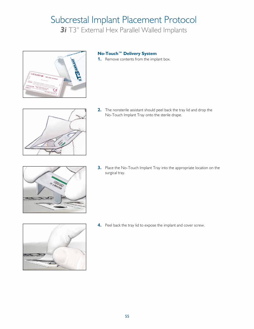
55
No-Touch™ Delivery System1. Remove contents from the implant box.
2. The nonsterile assistant should peel back the tray lid and drop the No-Touch Implant Tray onto the sterile drape.
3. Place the No-Touch Implant Tray into the appropriate location on the surgical tray.
4. Peel back the tray lid to expose the implant and cover screw.
Subcrestal Implant Placement Protocol3i T3® External Hex Parallel Walled Implants
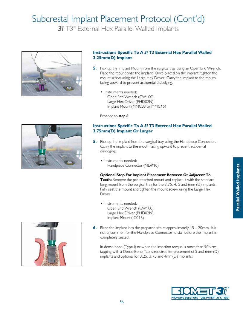
Subcrestal Implant Placement Protocol (Cont’d)3i T3® External Hex Parallel Walled Implants
56
Par
alle
l Wal
led
Impl
ants
Instructions Specific To A 3i T3 External Hex Parallel Walled 3.25mm(D) Implant
5. Pick up the Implant Mount from the surgical tray using an Open End Wrench. Place the mount onto the implant. Once placed on the implant, tighten the mount screw using the Large Hex Driver. Carry the implant to the mouth facing upward to prevent accidental dislodging.
• Instruments needed: Open End Wrench (CW100) Large Hex Driver (PHD02N) Implant Mount (MMC03 or MMC15)
Proceed to step 6.
Instructions Specific To A 3i T3 External Hex Parallel Walled 3.75mm(D) Implant Or Larger
5. Pick up the implant from the surgical tray using the Handpiece Connector. Carry the implant to the mouth facing upward to prevent accidental dislodging.
• Instruments needed: Handpiece Connector (MDR10)
Optional Step For Implant Placement Between Or Adjacent To Teeth: Remove the pre-attached mount and replace it with the standard long mount from the surgical tray for the 3.75, 4, 5 and 6mm(D) implants. Fully seat the mount and tighten the mount screw using the Large Hex Driver.
• Instruments needed: Open End Wrench (CW100) Large Hex Driver (PHD02N) Implant Mount (IC015)
6. Place the implant into the prepared site at approximately 15 – 20rpm. It is not uncommon for the Handpiece Connector to stall before the implant is completely seated. In dense bone (Type I) or when the insertion torque is more than 90Ncm, tapping with a Dense Bone Tap is required for placement of 5 and 6mm(D) implants and optional for 3.25, 3.75 and 4mm(D) implants.
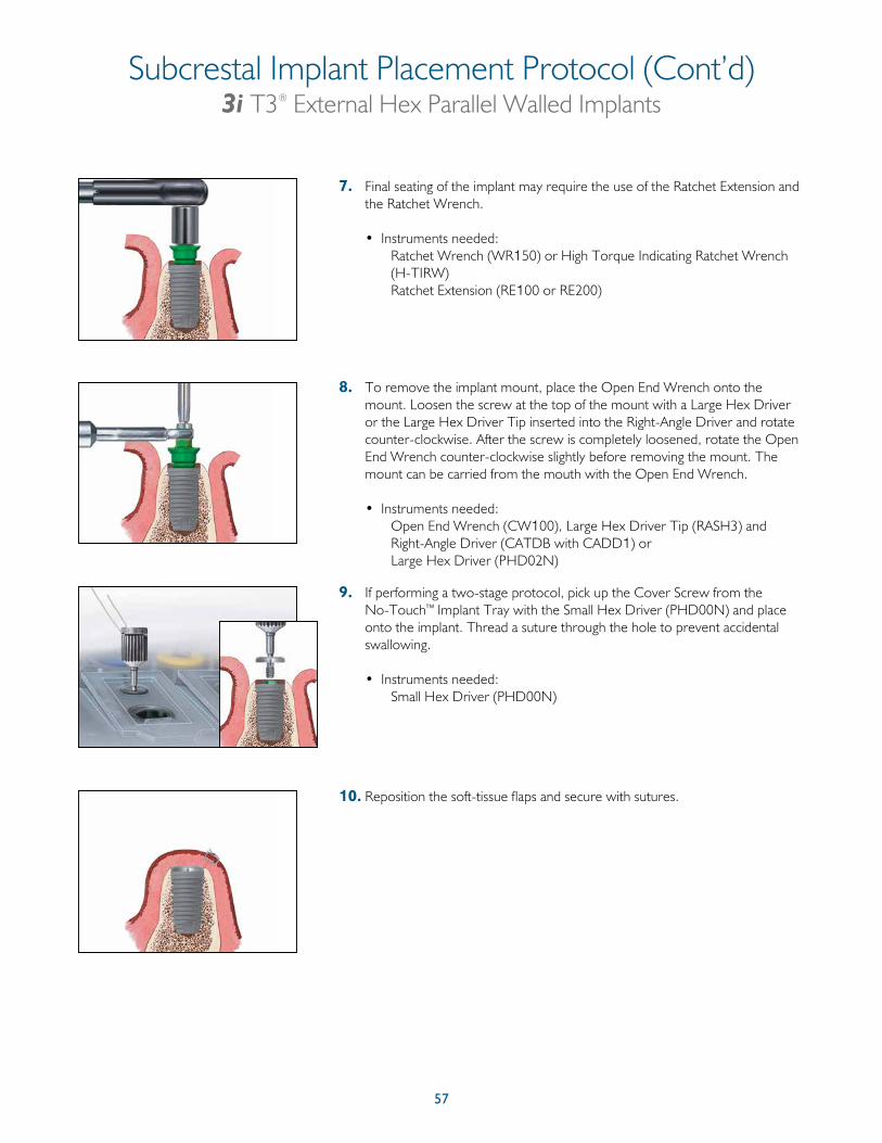
57
Subcrestal Implant Placement Protocol (Cont’d)3i T3® External Hex Parallel Walled Implants
7. Final seating of the implant may require the use of the Ratchet Extension and the Ratchet Wrench.
• Instruments needed: Ratchet Wrench (WR150) or High Torque Indicating Ratchet Wrench
(H-TIRW) Ratchet Extension (RE100 or RE200)
8. To remove the implant mount, place the Open End Wrench onto the mount. Loosen the screw at the top of the mount with a Large Hex Driver or the Large Hex Driver Tip inserted into the Right-Angle Driver and rotate counter-clockwise. After the screw is completely loosened, rotate the Open End Wrench counter-clockwise slightly before removing the mount. The mount can be carried from the mouth with the Open End Wrench.
• Instruments needed: Open End Wrench (CW100), Large Hex Driver Tip (RASH3) and Right-Angle Driver (CATDB with CADD1) or Large Hex Driver (PHD02N)
9. If performing a two-stage protocol, pick up the Cover Screw from the No-Touch™ Implant Tray with the Small Hex Driver (PHD00N) and place onto the implant. Thread a suture through the hole to prevent accidental swallowing.
• Instruments needed: Small Hex Driver (PHD00N)
10. Reposition the soft-tissue flaps and secure with sutures.
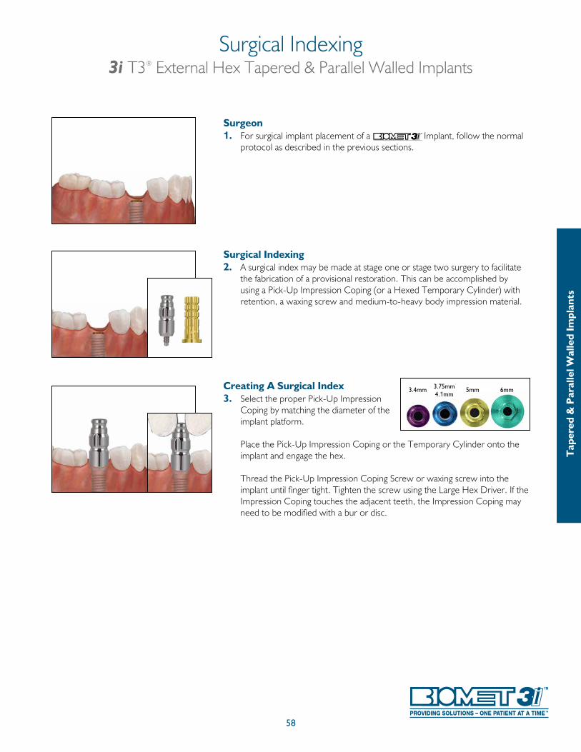
58
Surgeon 1. For surgical implant placement of a Implant, follow the normal
protocol as described in the previous sections.
Surgical Indexing2. A surgical index may be made at stage one or stage two surgery to facilitate
the fabrication of a provisional restoration. This can be accomplished by using a Pick-Up Impression Coping (or a Hexed Temporary Cylinder) with retention, a waxing screw and medium-to-heavy body impression material.
Creating A Surgical Index3. Select the proper Pick-Up Impression
Coping by matching the diameter of the implant platform.
Place the Pick-Up Impression Coping or the Temporary Cylinder onto the implant and engage the hex.
Thread the Pick-Up Impression Coping Screw or waxing screw into the implant until finger tight. Tighten the screw using the Large Hex Driver. If the Impression Coping touches the adjacent teeth, the Impression Coping may need to be modified with a bur or disc.
Surgical Indexing3i T3® External Hex Tapered & Parallel Walled Implants
5mm3.75mm4.1mm
3.4mm
Tap
ered
& P
aral
lel W
alle
d Im
plan
ts
6mm
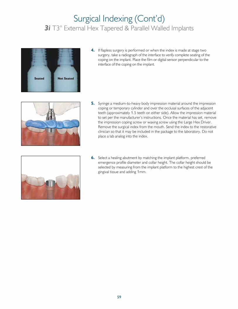
59
Seated Not Seated
4. If flapless surgery is performed or when the index is made at stage two surgery, take a radiograph of the interface to verify complete seating of the coping on the implant. Place the film or digital sensor perpendicular to the interface of the coping on the implant.
5. Syringe a medium-to-heavy body impression material around the impression coping or temporary cylinder and over the occlusal surfaces of the adjacent teeth (approximately 1.5 teeth on either side). Allow the impression material to set per the manufacturer’s instructions. Once the material has set, remove the impression coping screw or waxing screw using the Large Hex Driver. Remove the surgical index from the mouth. Send the index to the restorative clinician so that it may be included in the package to the laboratory. Do not place a lab analog into the index.
6. Select a healing abutment by matching the implant platform, preferred emergence profile diameter and collar height. The collar height should be selected by measuring from the implant platform to the highest crest of the gingival tissue and adding 1mm.
Surgical Indexing (Cont’d)3i T3® External Hex Tapered & Parallel Walled Implants
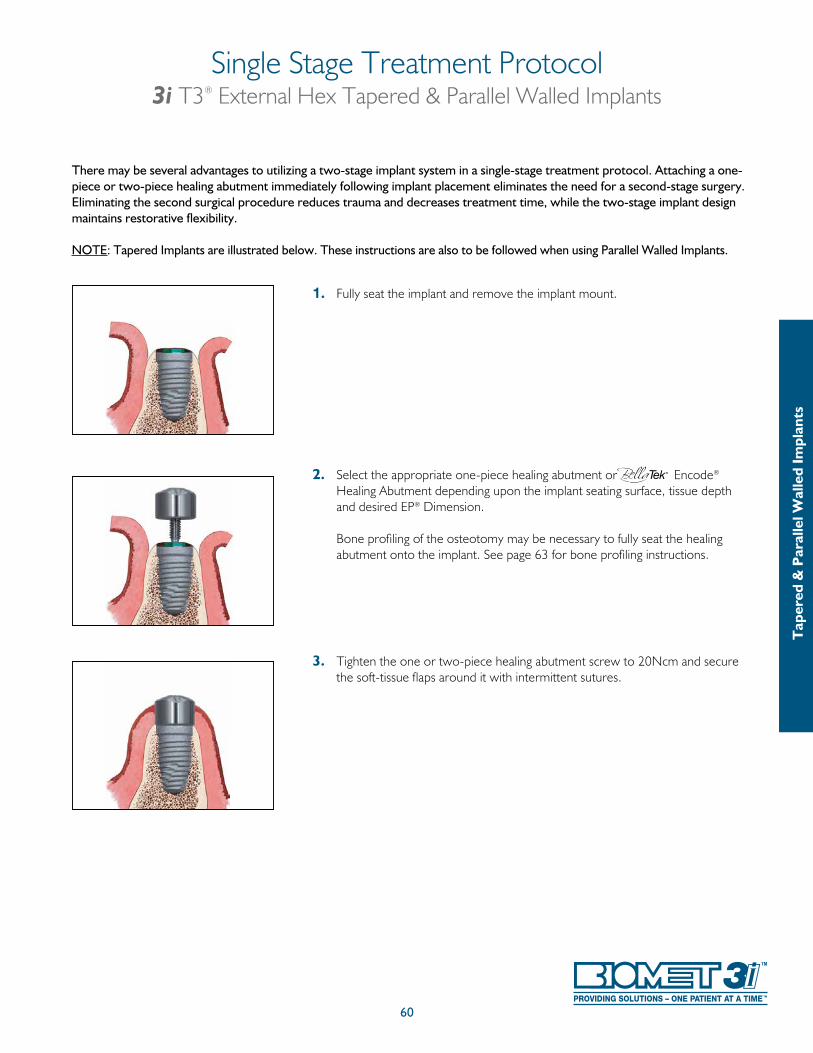
60
Single Stage Treatment Protocol3i T3® External Hex Tapered & Parallel Walled Implants
There may be several advantages to utilizing a two-stage implant system in a single-stage treatment protocol. Attaching a one-piece or two-piece healing abutment immediately following implant placement eliminates the need for a second-stage surgery. Eliminating the second surgical procedure reduces trauma and decreases treatment time, while the two-stage implant design maintains restorative flexibility.
NOTE: Tapered Implants are illustrated below. These instructions are also to be followed when using Parallel Walled Implants.
1. Fully seat the implant and remove the implant mount.
2. Select the appropriate one-piece healing abutment or Encode® Healing Abutment depending upon the implant seating surface, tissue depth and desired EP® Dimension.
Bone profiling of the osteotomy may be necessary to fully seat the healing abutment onto the implant. See page 63 for bone profiling instructions.
3. Tighten the one or two-piece healing abutment screw to 20Ncm and secure the soft-tissue flaps around it with intermittent sutures.
Tap
ered
& P
aral
lel W
alle
d Im
plan
ts
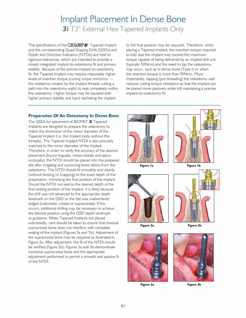
61
The specifications of the Tapered Implant and the corresponding Quad Shaping Drills (QSDs) and Depth and Direction Indicators (NTDIs) are held to rigorous tolerances, which are intended to provide a closely integrated implant-to-osteotomy fit and primary stability. Because of the precise implant-to-osteotomy fit, the Tapered Implant may require reasonably higher levels of insertion torque (cutting torque resistance — the resistance created by the implant threads cutting a path into the osteotomy walls) to seat completely within the osteotomy. Higher torque may be equated with higher primary stability and hand ratcheting the implant
to the final position may be required. Therefore, when placing a Tapered Implant, the insertion torque required to fully seat the implant may exceed the maximum torque capable of being delivered by an implant drill unit (typically 50Ncm) and the need to tap the osteotomy may occur, such as in dense bone (Type I) or when the insertion torque is more than 90Ncm. More importantly, tapping (pre-threading) the osteotomy wall reduces cutting torque resistance so that the implant can be placed more passively while still maintaining a precise implant-to-osteotomy fit.
The QSDs for placement of BIOMET 3i Tapered Implants are designed to prepare the osteotomy to match the dimension of the minor diameter of the Tapered Implant (i.e. the implant body without the threads). The Tapered Implant NTDI is also precisely matched to the minor diameter of the implant. Therefore, in order to verify the accuracy of the desired placement (bucco-lingually, mesio-distally and apico-occlusally), the NTDI should be placed into the prepared site after irrigating and suctioning bone debris from the osteotomy. The NTDI should fit smoothly and cleanly (without binding or snapping) to the exact depth of the preparation, mimicking the final position of the implant. Should the NTDI not seat to the desired depth of the final seating position of the implant, it is likely because the drill was not advanced to the appropriate depth landmark on the QSD or the site was inadvertently ledged (subcrestal, crestal or supracrestal). If this occurs, additional drilling may be necessary to achieve the desired position using the QSD depth landmark as guidance. When Tapered Implants are placed subcrestally, care should be taken to ensure that residual supracrestal bone does not interfere with complete seating of the implant (Figures 1a and 1b). Adjustment of the supracrestal bone may be required as illustrated in Figure 2a. After adjustment, the fit of the NTDI should be verified (Figure 2b). Figures 3a and 3b demonstrate excessive supracrestal bone and the appropriate adjustment performed to permit a smooth and passive fit of the NTDI.
Preparation Of An Osteotomy In Dense Bone
Figure 1a
Figure 2a Figure 2b
Figure 3a Figure 3b
Implant Placement In Dense Bone3i T3® External Hex Tapered Implants Only
Figure 1b
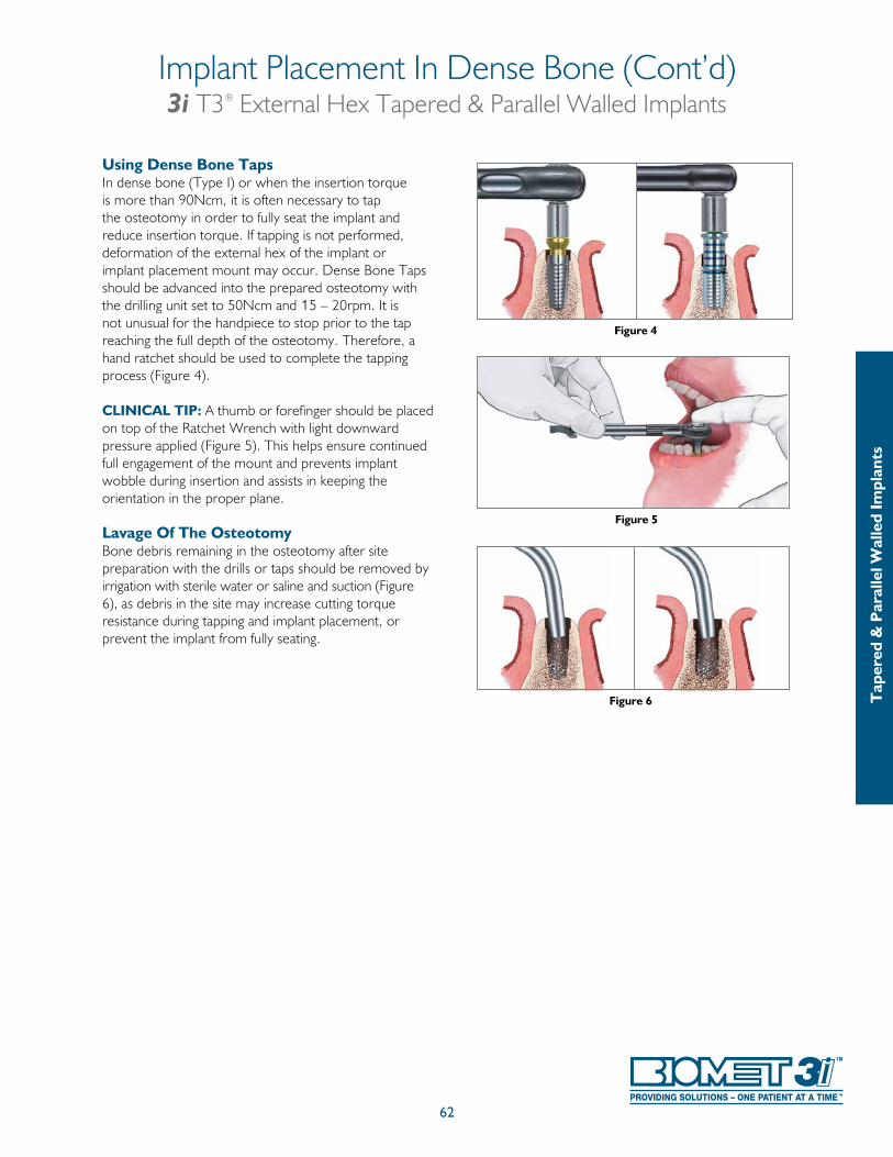
62
Using Dense Bone TapsIn dense bone (Type I) or when the insertion torque is more than 90Ncm, it is often necessary to tap the osteotomy in order to fully seat the implant and reduce insertion torque. If tapping is not performed, deformation of the external hex of the implant or implant placement mount may occur. Dense Bone Taps should be advanced into the prepared osteotomy with the drilling unit set to 50Ncm and 15 – 20rpm. It is not unusual for the handpiece to stop prior to the tap reaching the full depth of the osteotomy. Therefore, a hand ratchet should be used to complete the tapping process (Figure 4).
CLINICAL TIP: A thumb or forefinger should be placed on top of the Ratchet Wrench with light downward pressure applied (Figure 5). This helps ensure continued full engagement of the mount and prevents implant wobble during insertion and assists in keeping the orientation in the proper plane.
Lavage Of The OsteotomyBone debris remaining in the osteotomy after site preparation with the drills or taps should be removed by irrigation with sterile water or saline and suction (Figure 6), as debris in the site may increase cutting torque resistance during tapping and implant placement, or prevent the implant from fully seating.
Figure 4
Figure 5
Figure 6
Implant Placement In Dense Bone (Cont’d)3i T3® External Hex Tapered & Parallel Walled Implants
Tap
ered
& P
aral
lel W
alle
d Im
plan
ts
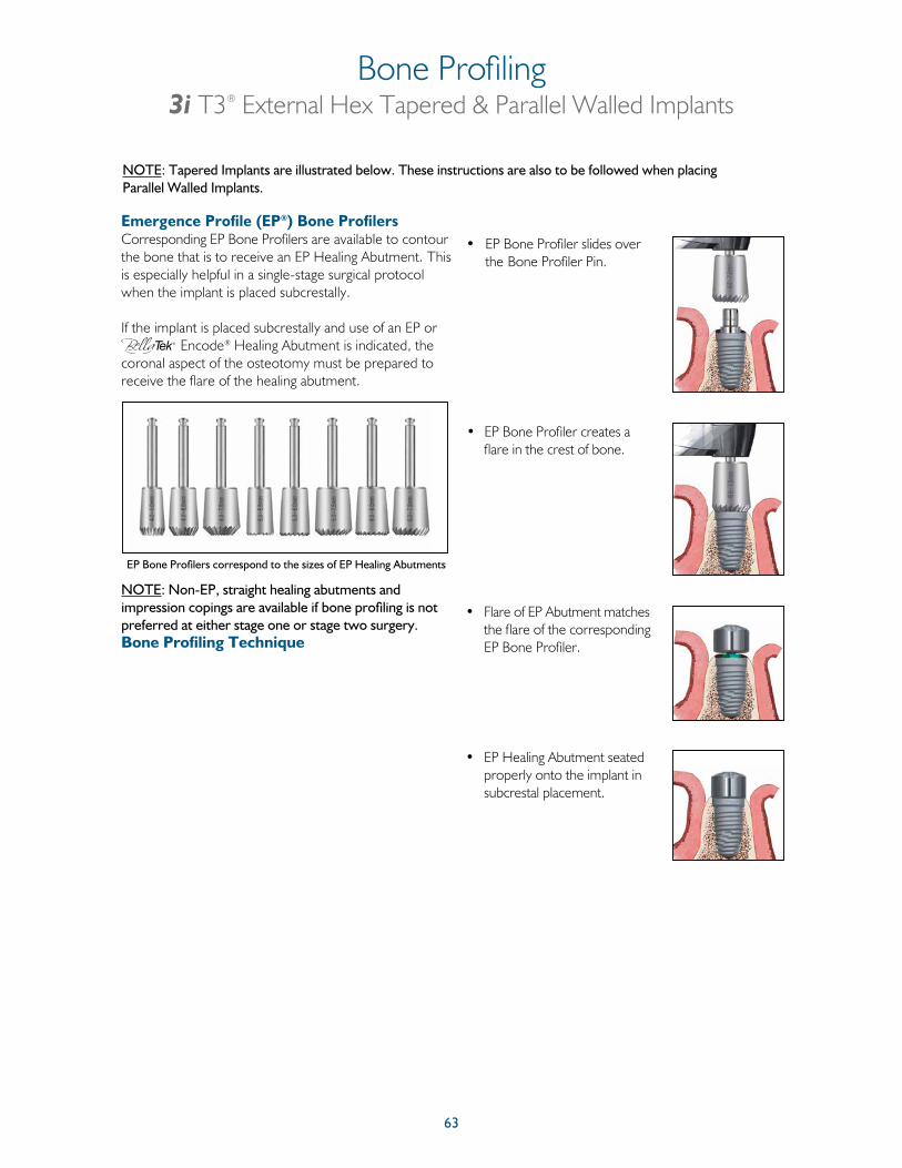
63
Emergence Profile (EP®) Bone Profilers Corresponding EP Bone Profilers are available to contour the bone that is to receive an EP Healing Abutment. This is especially helpful in a single-stage surgical protocol when the implant is placed subcrestally.
If the implant is placed subcrestally and use of an EP or
Encode® Healing Abutment is indicated, the coronal aspect of the osteotomy must be prepared to receive the flare of the healing abutment.
NOTE: Non-EP, straight healing abutments and impression copings are available if bone profiling is not preferred at either stage one or stage two surgery.Bone Profiling Technique
• EP Bone Profiler slides over the Bone Profiler Pin.
• EP Bone Profiler creates a flare in the crest of bone.
• Flare of EP Abutment matches the flare of the corresponding EP Bone Profiler.
• EP Healing Abutment seated properly onto the implant in subcrestal placement.
EP Bone Profilers correspond to the sizes of EP Healing Abutments
Bone Profiling3i T3® External Hex Tapered & Parallel Walled Implants
NOTE: Tapered Implants are illustrated below. These instructions are also to be followed when placing Parallel Walled Implants.

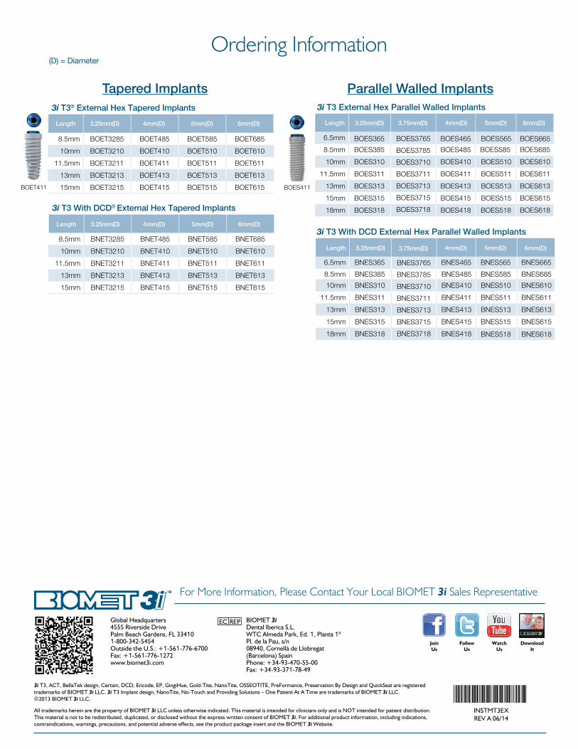
Global Headquarters4555 Riverside DrivePalm Beach Gardens, FL 334101-800-342-5454Outside the U.S.: +1-561-776-6700Fax: +1-561-776-1272www.biomet3i.com
BIOMET 3iDental Iberica S.L.WTC Almeda Park, Ed. 1, Planta 1ªPl. de la Pau, s/n08940, Cornellà de Llobregat(Barcelona) SpainPhone: +34-93-470-55-00Fax: +34-93-371-78-49
3i T3, ACT, BellaTek design, Certain, DCD, Encode, EP, GingiHue, Gold-Tite, NanoTite, OSSEOTITE, PreFormance, Preservation By Design and QuickSeat are registered trademarks of BIOMET 3i LLC. 3i T3 Implant design, NanoTite, No-Touch and Providing Solutions – One Patient At A Time are trademarks of BIOMET 3i LLC. ©2013 BIOMET 3i LLC.
All trademarks herein are the property of BIOMET 3i LLC unless otherwise indicated. This material is intended for clinicians only and is NOT intended for patient distribution. This material is not to be redistributed, duplicated, or disclosed without the express written consent of BIOMET 3i. For additional product information, including indications, contraindications, warnings, precautions, and potential adverse effects, see the product package insert and the BIOMET 3i Website.
INSTMT3EXREV A 06/14
For More Information, Please Contact Your Local BIOMET 3i Sales Representative
JoinUs
FollowUs
WatchUs
DownloadIt
Ordering Information(D) = Diameter
Tapered Implants3i T3® External Hex Tapered Implants
Length 3.25mm(D) 4mm(D) 5mm(D) 6mm(D)
BOET411
8.5mm BOET3285 BOET485 BOET585 BOET685
10mm BOET3210 BOET410 BOET510 BOET610
11.5mm BOET3211 BOET411 BOET511 BOET611
13mm BOET3213 BOET413 BOET513 BOET613
15mm BOET3215 BOET415 BOET515 BOET615
3i T3 With DCD® External Hex Tapered Implants
Length 3.25mm(D) 4mm(D) 5mm(D) 6mm(D)
8.5mm BNET3285 BNET485 BNET585 BNET685
10mm BNET3210 BNET410 BNET510 BNET610
11.5mm BNET3211 BNET411 BNET511 BNET611
13mm BNET3213 BNET413 BNET513 BNET613
15mm BNET3215 BNET415 BNET515 BNET615
Parallel Walled Implants3i T3 External Hex Parallel Walled Implants
Length 3.25mm(D) 3.75mm(D) 4mm(D) 5mm(D) 6mm(D)
8.5mm BOES385 BOES485 BOES585 BOES685
10mm BOES310 BOES410 BOES510 BOES610
11.5mm BOES311 BOES411 BOES511 BOES611
13mm BOES313 BOES413 BOES513 BOES613
15mm BOES315 BOES415 BOES515 BOES615
BOES61818mm BOES318 BOES418 BOES518
BOES411
3i T3 With DCD External Hex Parallel Walled Implants
Length 3.25mm(D) 4mm(D) 5mm(D)
8.5mm BNES385 BNES485 BNES585 BNES685
6.5mm BNES365 BNES465 BNES565 BNES665
6.5mm
10mm BNES310 BNES410 BNES510 BNES610
11.5mm BNES311 BNES411 BNES511 BNES611
13mm BNES313 BNES413 BNES513 BNES613
15mm BNES315 BNES415 BNES515 BNES615
BNES518 BNES61818mm BNES318 BNES418
BOES365 BOES465 BOES565 BOES665
6mm(D)
BOES3765
BOES3785
BOES3710
BOES3711
BOES3713
BOES3715
BOES3718
3.75mm(D)
BNES3765
BNES3785
BNES3710
BNES3711
BNES3713
BNES3715
BNES3718
EC REP