Embed Size (px)
Citation preview
HCMR.ALL.D-2-4-v.0.4 30-06-11 1 (27)
Surfacing System for Ship Recovery
Wednesday, 3 June 2011
D-2-4 Definition of a buoyancy rescue concept for three scenarios The information contained in this report is subject to change without notice and should not be construed as a commitment by any members of the SUSY Consortium. In the event of any software or algorithms being described in this report, the SUSY Consortium assumes no responsibility for the use or inability to use any of its software or algorithms. The information is provided without any warranty of any kind and the SUSY Consortium expressly disclaims all implied warranties, including but not limited to the implied warranties of merchantability and fitness for a particular use.
COPYRIGHT 2009 The SUSY Consortium
This document may not be copied, reproduced, or modified in whole or in part for any purpose without written permission from the SUSY Consortium. In addition, to such written permission to copy, acknowledgement of the authors of the document and all applicable portions of the copyright notice must be clearly referenced.
All rights reserved.
Definition of a buoyancy rescue concept for three scenarios
D2.4 Definition of a buoyancy rescue concept for three scenarios 2
ABSTRACT The objective of this task is to define the concept for three buoyancy rescue scenarios. The scenarios follow typical distress conditions of damaged vessels; on the surface with internal SuSy system, on the surface and adding external SuSy systems and using SuSy to recover a sunken vessel. The environmental conditions that may impact rescue scenarios are considered (at the surface, sub-surface and on the seabed).
DocumentName:Definition of a buoyancy rescue concepts for three scenarios
DocumentAuthor/s: C. Smith, S. Volonakis, E. Chatzidouros, I. Zilakos
DocumentEditors V.J. Papazoglou
DocumentReferenceNumber: D.2.4 v.04 03.06.11
Circulation: All
SecurityStatus Project internal
Definition of a buoyancy rescue concept for three scenarios
D2.4 Definition of a buoyancy rescue concept for three scenarios 3
Table of contents
1 INTRODUCTION .......................................................................................................................... 4
2 GENERAL PRE-REQUISITES .................................................................................................... 4
3 INTERNAL DEPLOYMENT OF SUSY CONCEPT DEVICE ..................................................... 5
3.1 PARAMETERS TO BE CONSIDERED ................................................................................................ 7
4 EXTERNAL DEPLOYMENT OF SUSY CONCEPT DEVICE .................................................... 9
4.1 APPLICATION OF THE SUSY DEVICE ON A DAMAGED TANKER ....................................................... 9
4.1.1 Description ........................................................................................................................... 9
4.1.2 Loading & boundary conditions ...................................................................................... 11
4.1.3 Damage case .................................................................................................................... 11
4.1.4 Application to the damaged tanker ................................................................................ 12
4.1.5 Results ............................................................................................................................... 13
4.1.6 Conclusion ......................................................................................................................... 16
4.2 PARAMETERS TO BE CONSIDERED .............................................................................................. 17
5 SUNKEN VESSEL ..................................................................................................................... 17
5.1 PARAMETERS TO BE CONSIDERED .............................................................................................. 18
5.1.1 Vessel Considered ........................................................................................................... 18
5.1.2 Depth of Sunken Ship (hypothesis) ............................................................................... 19
5.1.3 Residual Structural Strength ........................................................................................... 19
5.1.4 The Stability of the Ship as the Lift Commences ......................................................... 19
5.2 BASIC HYDROSTATIC CALCULATIONS ......................................................................................... 20
5.2.1 Buoyancy Required for Lift .............................................................................................. 20
5.2.2 Centre of Gravity ............................................................................................................... 21
5.3 DYNAMIC CONSIDERATIONS ........................................................................................................ 21
5.3.1 Solve Venting Requirements for Continuous Lifting Speed ....................................... 21
5.3.2 Centre of Buoyancy .......................................................................................................... 22
5.3.3 Solutions and Control for Venting Problem .................................................................. 22
5.4 ATTACHMENT & RIGGING ............................................................................................................ 22
5.5 CONTINUOUS LIFTING SPEED ...................................................................................................... 22
5.6 PRESSURE RELIEF ....................................................................................................................... 23
5.7 AUTOMATIC CONTROL ................................................................................................................. 23
6 ENVIRONMENTAL CONDITIONS ........................................................................................... 23
6.1 INTRODUCTION ............................................................................................................................. 23
6.2 ENVIRONMENTAL CONDITIONS .................................................................................................... 24
6.2.1 Surface Environment ........................................................................................................ 24
6.2.1.1 Air Conditions .................................................................................................................... 24
6.2.1.2 Sea Conditions .................................................................................................................. 25
6.2.2 Sub-surface Environment ................................................................................................ 26
6.2.2.1 Sea Conditions .................................................................................................................. 26
6.2.2.2 Seabed Conditions ........................................................................................................... 26
6.2.3 Casualty Impacts on the Environment ................................................................................. 27
7 REFERENCES ........................................................................................................................... 27
Definition of a buoyancy rescue concept for three scenarios
D2.4 Definition of a buoyancy rescue concept for three scenarios 4
1 Introduction
Within the framework of the “SUSY” project, three buoyancy rescue scenarios will be examined regarding typical distress conditions for specific vessels. In particular the first two rescue scenarios will be applied to a specific AFRAMAX Tanker, which has been chosen to test the SuSy system. The aforementioned tanker has been presented in detail in deliverable 2.3.
These two scenarios refer to a floating vessel, which has sustained damage resulting in a loss of buoyancy. The distinction between these two scenarios is the application of SuSy devices, which in the first scenario is internal and in the second external.
The third scenario refers to a sunken vessel. The vessel is lying on the seabed and the SuSy devices will be attached to the vessel during salvage operations and will be used to lift the vessel to the surface. The vessel that should be chosen for this scenario is a no more that 500 t Lightship. Further details regarding this vessel have yet to be defined.
For each scenario a number of specific important parameters that are considered for the scenarios including for example, inflation speed, pressure relief and system control. Environmental conditions are also considered covering all conditions that may have an impact on the scenario operations
2 General Pre-requisites
The SuSy system must be classified according to its level of danger/risk and must be handled under the existing conditions for those classifications (safety and security). The concept must insure that under all scenarios a number of pre-requisites are met.
Personnel safety:
The concept must be within certification rules that govern personnel safety. For a ship installed system, this concerns when personnel are working with the system (installation or maintenance) when in normal working position (installed), or in storage and transportation of the portable salvage systems. The major danger would be premature initiation either leading to a release of gas or heat or from impact from inflating balloon or a projected gas generator.
Ship Safety:
The concept must be within certification rules that govern ship safety. There should be no incurred risk to the ship by the installation, storage or operation of the system. External deployment of SuSy devices will result in the concentration of loads. The system can only be attached in load bearing areas, but even so this may compromise an already damaged vessel.
Mobile Rescue Squads;
Beyond the safety to personnel on board vessels and the vessels themselves, the system should incur any risk beyond certification of other transport or storage systems under normal/expected environmental conditions. System design must allow for mobility and safety in movement taking into account the full range of hazards in movement.
Definition of a buoyancy rescue concept for three scenarios
D2.4 Definition of a buoyancy rescue concept for three scenarios 5
Surfacing Support for Wrecks:
The SuSy system will provide near instantaneous buoyancy within a confined area, to an external point near or above the water surface or to a submerged casualty. At the surface this may provide stability over long or short term, the later maybe just giving time to evacuate a vessel. In the event of either not maintaining stability or in being used to bring a casualty to the surface, further salvage actions will be needed e.g. in the provision of further buoyancy, damage repair, removal of cargo, or removal of the casualty to a safer environment. In any of these cases the use of the SuSy system is just one step during the salvage process, and many further steps may be needed to finally secure the casualty.
3 Internal Deployment of SuSy concept device
Internal deployment of the SuSy device is envisioned through pre-fitting of the system in existing ships. These devices will restore the buoyancy lost due to damage. The test bed for the feasibility and evaluation of the SuSy device is an AFRAMAX Tanker. Simulations and experiments have been conducted using a double bottom section of the aforementioned vessel. More complete details are reported through Deliverable 2.3 Requirement for the vessel design selected in the typical scenarios.
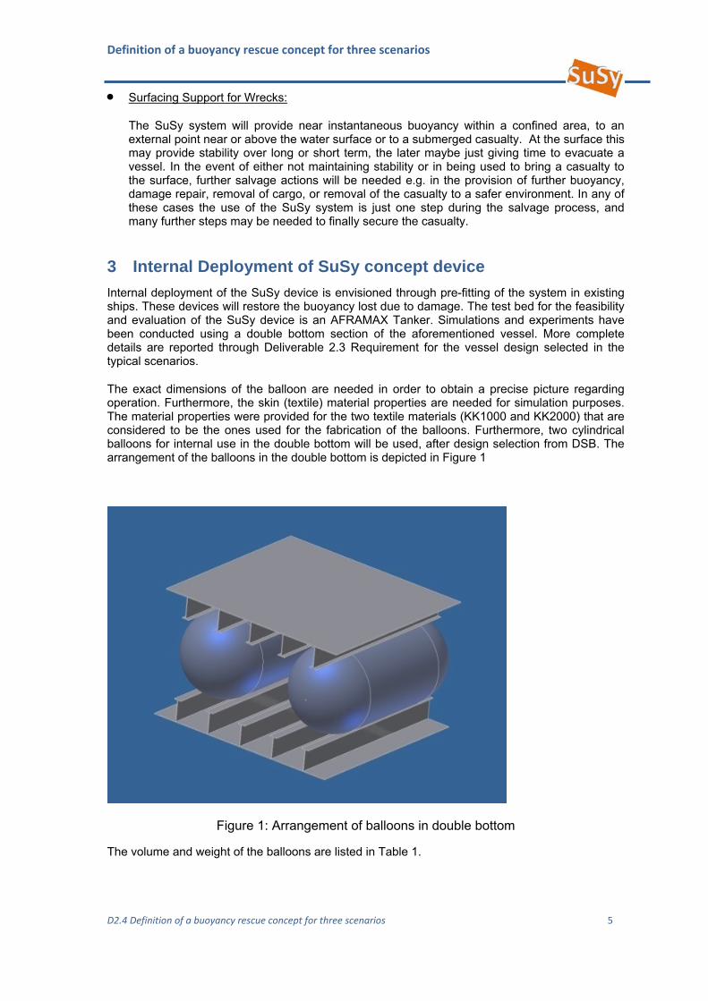
The exact dimensions of the balloon are needed in order to obtain a precise picture regarding operation. Furthermore, the skin (textile) material properties are needed for simulation purposes. The material properties were provided for the two textile materials (KK1000 and KK2000) that are considered to be the ones used for the fabrication of the balloons. Furthermore, two cylindrical balloons for internal use in the double bottom will be used, after design selection from DSB. The arrangement of the balloons in the double bottom is depicted in Figure 1
Figure 1: Arrangement of balloons in double bottom
The volume and weight of the balloons are listed in Table 1.
Definition of a buoyancy rescue concept for three scenarios
D2.4 Definition of a buoyancy rescue concept for three scenarios 6
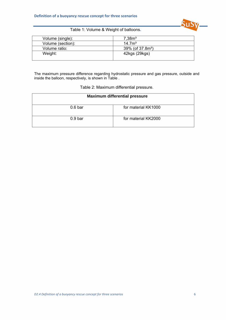
Table 1: Volume & Weight of balloons.
Volume (single): 7,38m³ Volume (section): 14.7m³ Volume ratio: 39% (of 37.8m³) Weight: 42kgs (29kgs)
The maximum pressure difference regarding hydrostatic pressure and gas pressure, outside and inside the balloon, respectively, is shown in Table .
Table 2: Maximum differential pressure.
Maximum differential pressure
0.6 bar for material KK1000
0.9 bar for material KK2000
Definition of a buoyancy rescue concept for three scenarios
D2.4 Definition of a buoyancy rescue concept for three scenarios 7
3.1 Parameters to be considered Automatic Control
As the system will be pre-installed in vessels, the Susy system must be centrally controlled in most cases from the bridge or operational control centre on the vessel. Provision may be made for individual control from deck level above or in vicinity to the installed SuSy systems. There should not be provision for automatic control.
Inflation Speed
In order to restore buoyancy to the damaged floating vessel, a steady state and slow rate inflation is desirable, in order to avoid impact loads on the structure. This would be in the order of more than a few seconds duration. Inflation speed should be fast enough to ensure that stability can be met within a reasonable time frame. Inflation should therefore be completed within minutes.
Pressure relief
Pressure relief during inflation and righting must be used in order to maintain an equilibrium between external (hydrostatic) and internal (gas) pressure. Simulations have already been conducted in order to investigate pressure relief of the SuSy device deployed inside the double bottom of the AFRAMAX tanker. The results indicate that there is no impact regarding the residual structural strength of the double bottom. Both simulations and results are described and discussed in Deliverable-2-3 Report on Requirements from the Vessel Design.
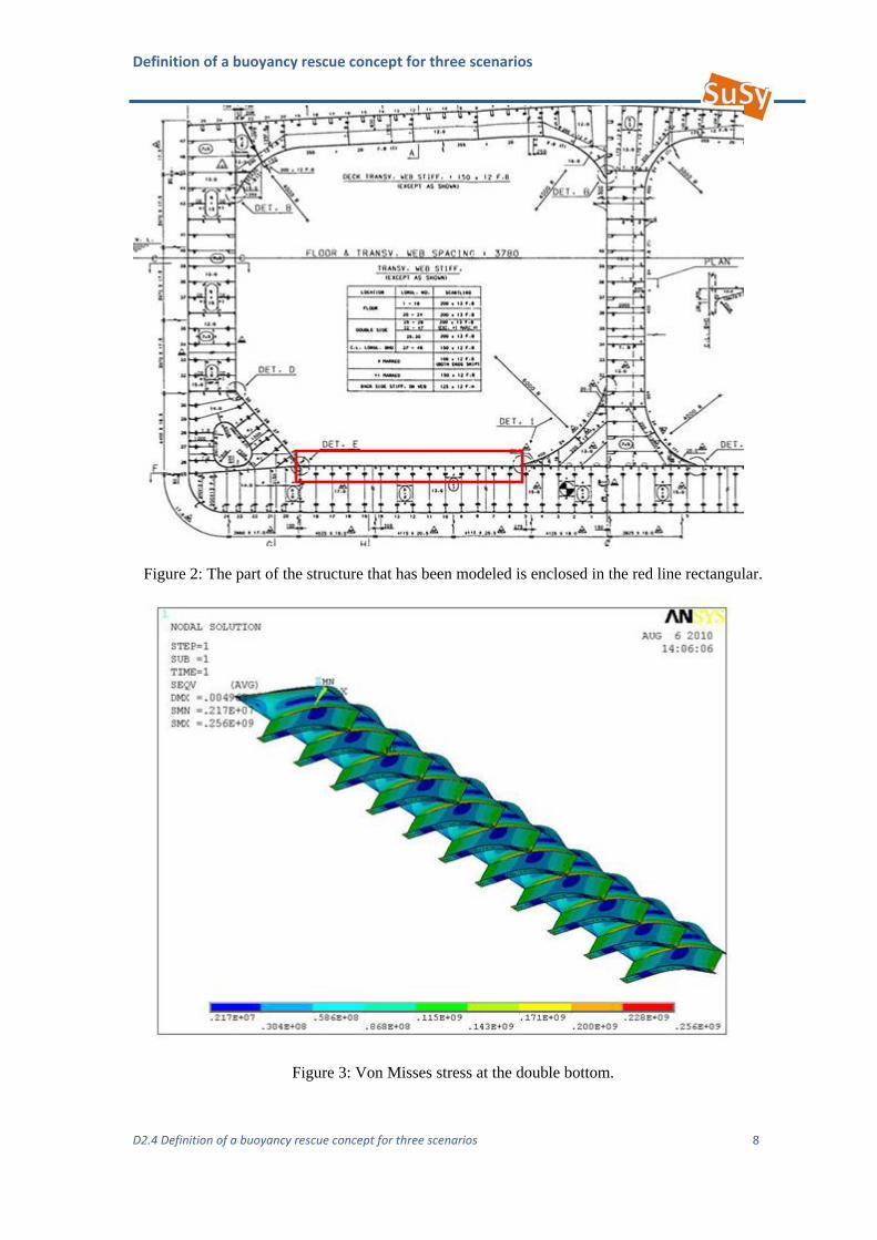
The results regarding the pressure of the air escaping from the balloons in the double bottom are given for 20 m sea depth, as discussed in the SuSy Lorient Meeting (June 2010). This is the worst case scenario, where there is no oil or other liquid in the tanks to compensate for the pressure acting in the double bottom. The inner structure of the double bottom is subjected to 200 kPa pressure, equal to 20 m sea depth.
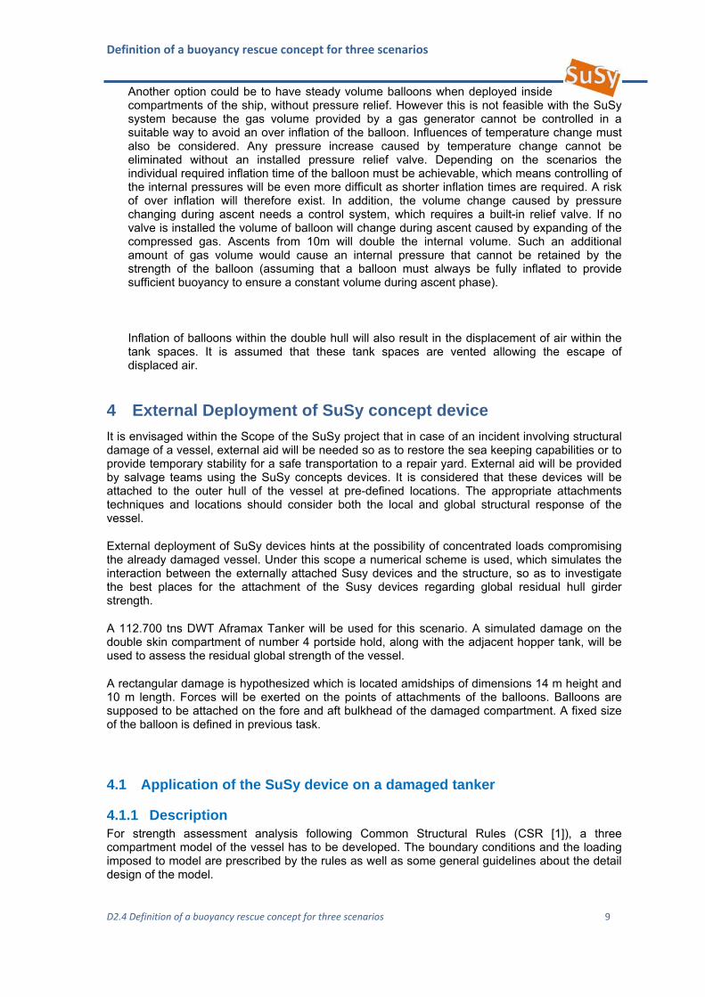
The part of the structure that is modelled is outlined in Figure 2. The results of the analysis are illustrated in a contour plot of Von Misses stress. Figure illustrates that the maximum Von Misses stress is 256 MPa which is lower than the yield stress of the AH steel of the stiffeners and the plating (315 MPa).
It is noted that the inner bottom stiffened plating is designed to withstand the pressure from the oil from the overhead tank.
In this manner the aforementioned results were expected.
Definition of a buoyancy rescue concept for three scenarios
D2.4 Definition of a buoyancy rescue concept for three scenarios 8
Figure 2: The part of the structure that has been modeled is enclosed in the red line rectangular.
Figure 3: Von Misses stress at the double bottom.
Definition of a buoyancy rescue concept for three scenarios
D2.4 Definition of a buoyancy rescue concept for three scenarios 9
Another option could be to have steady volume balloons when deployed inside compartments of the ship, without pressure relief. However this is not feasible with the SuSy system because the gas volume provided by a gas generator cannot be controlled in a suitable way to avoid an over inflation of the balloon. Influences of temperature change must also be considered. Any pressure increase caused by temperature change cannot be eliminated without an installed pressure relief valve. Depending on the scenarios the individual required inflation time of the balloon must be achievable, which means controlling of the internal pressures will be even more difficult as shorter inflation times are required. A risk of over inflation will therefore exist. In addition, the volume change caused by pressure changing during ascent needs a control system, which requires a built-in relief valve. If no valve is installed the volume of balloon will change during ascent caused by expanding of the compressed gas. Ascents from 10m will double the internal volume. Such an additional amount of gas volume would cause an internal pressure that cannot be retained by the strength of the balloon (assuming that a balloon must always be fully inflated to provide sufficient buoyancy to ensure a constant volume during ascent phase).
Inflation of balloons within the double hull will also result in the displacement of air within the tank spaces. It is assumed that these tank spaces are vented allowing the escape of displaced air.
4 External Deployment of SuSy concept device
It is envisaged within the Scope of the SuSy project that in case of an incident involving structural damage of a vessel, external aid will be needed so as to restore the sea keeping capabilities or to provide temporary stability for a safe transportation to a repair yard. External aid will be provided by salvage teams using the SuSy concepts devices. It is considered that these devices will be attached to the outer hull of the vessel at pre-defined locations. The appropriate attachments techniques and locations should consider both the local and global structural response of the vessel.
External deployment of SuSy devices hints at the possibility of concentrated loads compromising the already damaged vessel. Under this scope a numerical scheme is used, which simulates the interaction between the externally attached Susy devices and the structure, so as to investigate the best places for the attachment of the Susy devices regarding global residual hull girder strength.
A 112.700 tns DWT Aframax Tanker will be used for this scenario. A simulated damage on the double skin compartment of number 4 portside hold, along with the adjacent hopper tank, will be used to assess the residual global strength of the vessel.
A rectangular damage is hypothesized which is located amidships of dimensions 14 m height and 10 m length. Forces will be exerted on the points of attachments of the balloons. Balloons are supposed to be attached on the fore and aft bulkhead of the damaged compartment. A fixed size of the balloon is defined in previous task.
4.1 Application of the SuSy device on a damaged tanker
4.1.1 Description For strength assessment analysis following Common Structural Rules (CSR [1]), a three compartment model of the vessel has to be developed. The boundary conditions and the loading imposed to model are prescribed by the rules as well as some general guidelines about the detail design of the model.
Definition of a buoyancy rescue concept for three scenarios
D2.4 Definition of a buoyancy rescue concept for three scenarios 10
Under this scope a three compartment model was developed using ABAQUS 6.10.2 [2] for strength assessment and applied for a specific load case. The loads and boundary conditions imposed to the model as well as the type of elements and analysis are in full accordance with the CSR. Furthermore a subroutine, written in FORTRAN code, which has already been developed in STL, was used for strength assessment of the vessel. The subroutine can be called by ABAQUS during the FE analysis. The procedure, regarding strength assessment following the CSR is described in detail in Appendix A.
This report refers to the study of external application of a SuSy device on an Aframax Tanker that has been structurally compromised, using the finite element method and following the IACS CSR rules for Oil Tankers. A damage condition is assessed, where the middle compartment is compromised on the starboard side and the Tanker is heeling. The damage condition is simulated using the three compartment finite element model, which has been developed, along with a simulated damage on the middle compartment. The residual hull girder strength is evaluated and compared to the undamaged case. Subsequently reserve buoyancy is introduced on the damaged side of the Tanker, in terms of attached balloons on the outer hull of the vessel, for the purpose of bringing the ship to an upright position. The effect of the forces exerted from the attached balloons on the vessel is studied, considering global ship strength. The global ship strength is evaluated considering the most suitable areas for attaching the balloons aimed at lowering the stress peaks that appear on the damaged compartment of the vessel.
In the present work the external use of the SuSy devices on a structurally damaged double skin Aframax Tanker is investigated. This is accomplished by assessing the global structural response of the damaged vessel, with and without the SuSy devices.
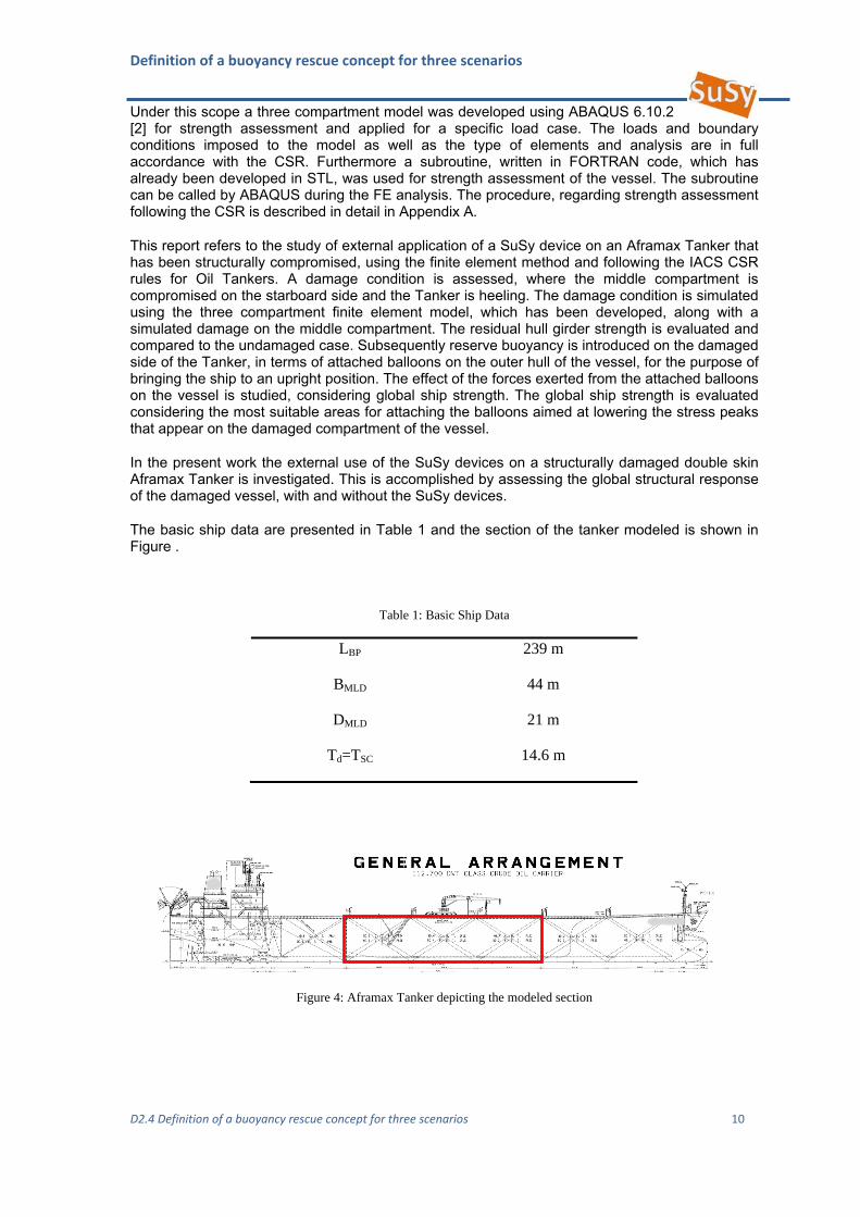
The basic ship data are presented in Table 1 and the section of the tanker modeled is shown in Figure .
Table 1: Basic Ship Data
LBP 239 m
BMLD 44 m
DMLD 21 m
Td=TSC 14.6 m
Figure 4: Aframax Tanker depicting the modeled section
Definition of a buoyancy rescue concept for three scenarios
D2.4 Definition of a buoyancy rescue concept for three scenarios 11
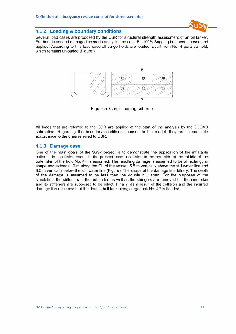
4.1.2 Loading & boundary conditions Several load cases are proposed by the CSR for structural strength assessment of an oil tanker. For both intact and damaged scenario analysis, the case B1-100% Sagging has been chosen and applied. According to this load case all cargo holds are loaded, apart from No. 4 portside hold, which remains unloaded (Figure ).
Figure 5: Cargo loading scheme
All loads that are referred to the CSR are applied at the start of the analysis by the DLOAD subroutine. Regarding the boundary conditions imposed to the model, they are in complete accordance to the ones referred to CSR.
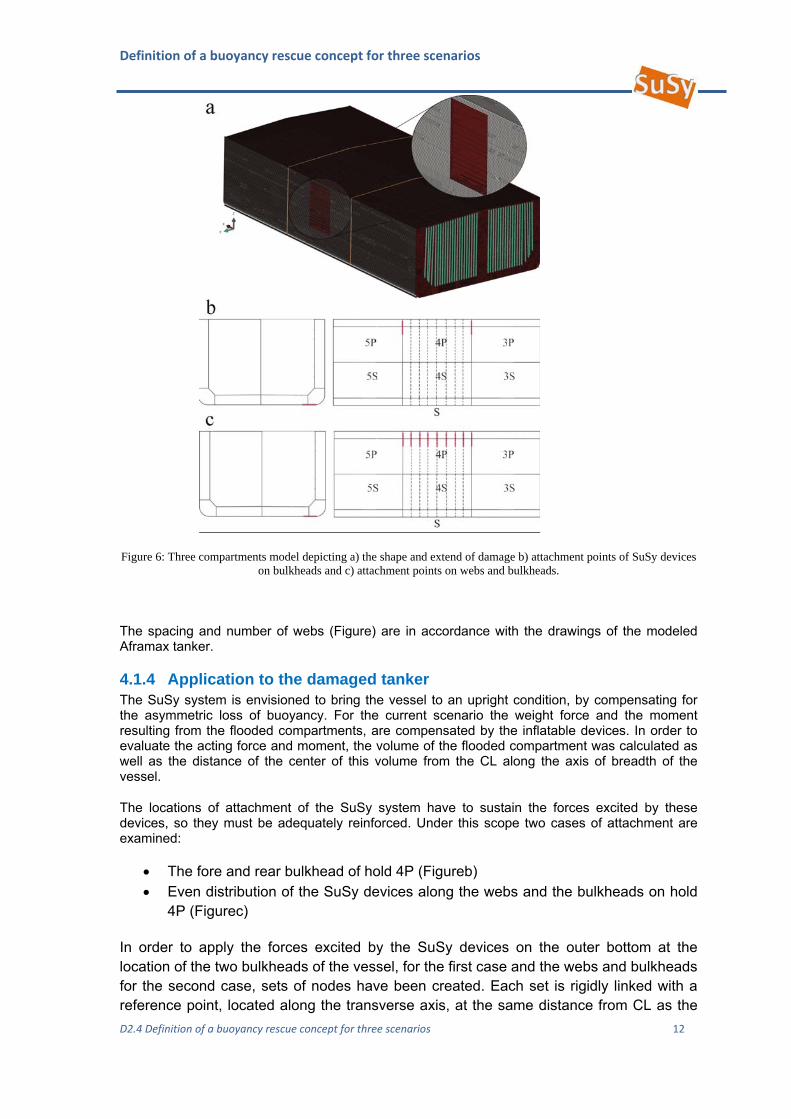
4.1.3 Damage case One of the main goals of the SuSy project is to demonstrate the application of the inflatable balloons in a collision event. In the present case a collision to the port side at the middle of the outer skin of the hold No. 4P is assumed. The resulting damage is assumed to be of rectangular shape and extends 10 m along the CL of the vessel, 5.5 m vertically above the still water line and 8.5 m vertically below the still water line (Figure). The shape of the damage is arbitrary. The depth of the damage is assumed to be less than the double hull span. For the purposes of the simulation, the stiffeners of the outer skin as well as the stringers are removed but the inner skin and its stiffeners are supposed to be intact. Finally, as a result of the collision and the incurred damage it is assumed that the double hull tank along cargo tank No. 4P is flooded.
Definition of a buoyancy rescue concept for three scenarios
D2.4 Definition of a buoyancy rescue concept for three scenarios 12
Figure 6: Three compartments model depicting a) the shape and extend of damage b) attachment points of SuSy devices on bulkheads and c) attachment points on webs and bulkheads.
The spacing and number of webs (Figure) are in accordance with the drawings of the modeled Aframax tanker.
4.1.4 Application to the damaged tanker The SuSy system is envisioned to bring the vessel to an upright condition, by compensating for the asymmetric loss of buoyancy. For the current scenario the weight force and the moment resulting from the flooded compartments, are compensated by the inflatable devices. In order to evaluate the acting force and moment, the volume of the flooded compartment was calculated as well as the distance of the center of this volume from the CL along the axis of breadth of the vessel.
The locations of attachment of the SuSy system have to sustain the forces excited by these devices, so they must be adequately reinforced. Under this scope two cases of attachment are examined:
The fore and rear bulkhead of hold 4P (Figureb) Even distribution of the SuSy devices along the webs and the bulkheads on hold
4P (Figurec)
In order to apply the forces excited by the SuSy devices on the outer bottom at the location of the two bulkheads of the vessel, for the first case and the webs and bulkheads for the second case, sets of nodes have been created. Each set is rigidly linked with a reference point, located along the transverse axis, at the same distance from CL as the
Definition of a buoyancy rescue concept for three scenarios
D2.4 Definition of a buoyancy rescue concept for three scenarios 13
center of the volume of water in the flooded compartment. The weight force of the flooded compartment is equally distributed and applied to the reference points.
4.1.5 Results In this particular damage case three alternative scenarios were studied. The first two considered the external application of the SuSy devices in order to compensate for the loss of buoyancy. The third one refers to a practice occasionally used, of ballasting the double skin and hopper tanks opposite to the damaged ones, in order to bring the vessel to the upright position.
The FE results were visualized by plotting Von Misses (VM) stresses in order to evaluate the structural response of the vessel. Since the material is linear elastic the threshold of the VM stresses depicted in Figure -9 is selected to be the yield stress of the AH36 steel. Higher values than the yield stress cannot be considered since plasticity is not incorporated in this analysis. Furthermore the lower plotting threshold of the VM stresses in Figure -9 is 10 MPa. Lower values appear in black color.
In all three cases the average VM stress distribution on the structure, is below the yield stress of steel AH36, thus the use of only the elastic properties of the material doesn’t affect the results. Some stress concentration points are present, which are located in the damage area and are highly localized.
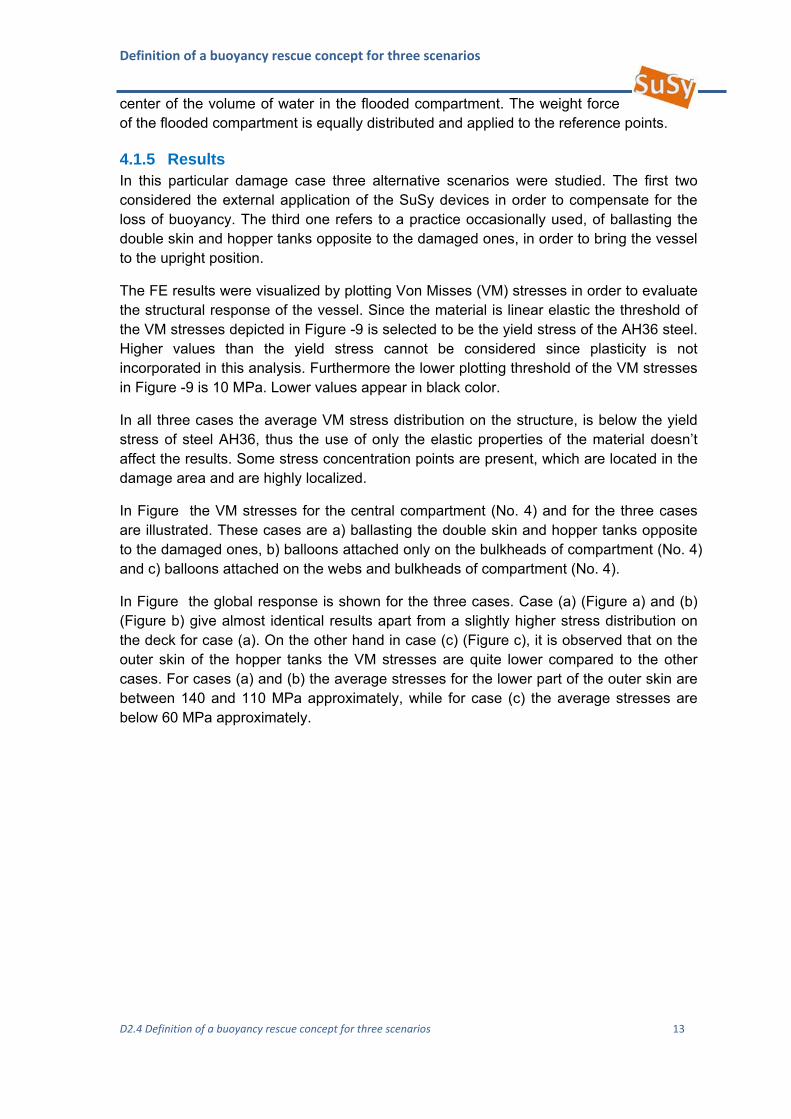
In Figure the VM stresses for the central compartment (No. 4) and for the three cases are illustrated. These cases are a) ballasting the double skin and hopper tanks opposite to the damaged ones, b) balloons attached only on the bulkheads of compartment (No. 4) and c) balloons attached on the webs and bulkheads of compartment (No. 4).
In Figure the global response is shown for the three cases. Case (a) (Figure a) and (b) (Figure b) give almost identical results apart from a slightly higher stress distribution on the deck for case (a). On the other hand in case (c) (Figure c), it is observed that on the outer skin of the hopper tanks the VM stresses are quite lower compared to the other cases. For cases (a) and (b) the average stresses for the lower part of the outer skin are between 140 and 110 MPa approximately, while for case (c) the average stresses are below 60 MPa approximately.
Definition of a buoyancy rescue concept for three scenarios
D2.4 Definition of a buoyancy rescue concept for three scenarios 14
Figure 7: VM stresses on the central compartment of the vessel for the three cases; a) ballasting the double skin and hopper tanks opposite to the damaged ones, b) balloons attached on the bulkheads of compartment No. 4 and c) balloons attached on the webs and bulkheads of compartment No. 4.
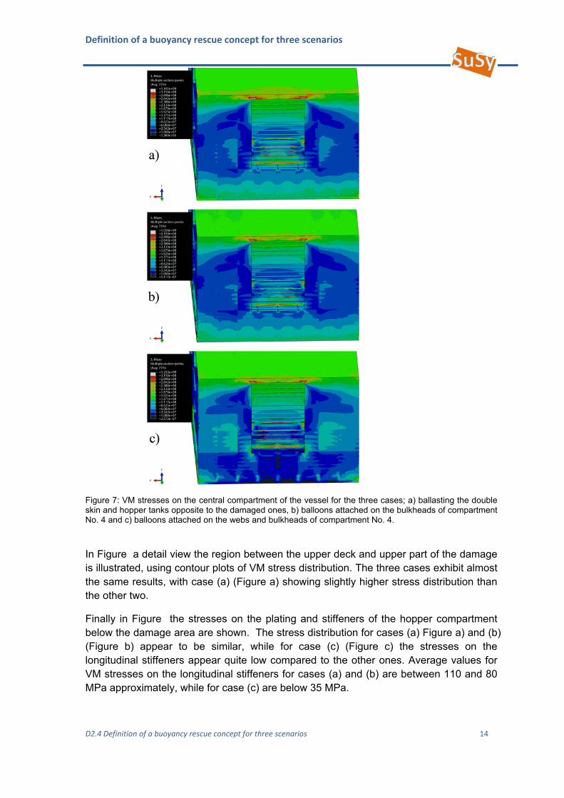
In Figure a detail view the region between the upper deck and upper part of the damage is illustrated, using contour plots of VM stress distribution. The three cases exhibit almost the same results, with case (a) (Figure a) showing slightly higher stress distribution than the other two.
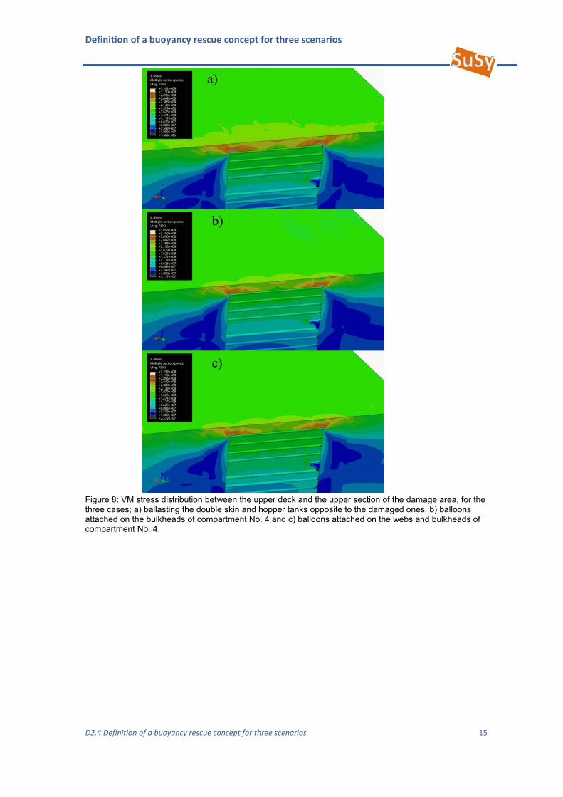
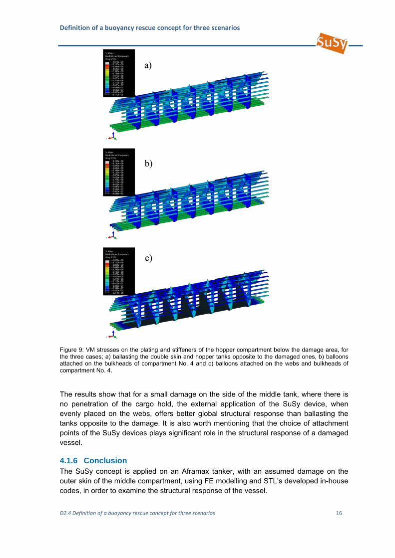
Finally in Figure the stresses on the plating and stiffeners of the hopper compartment below the damage area are shown. The stress distribution for cases (a) Figure a) and (b) (Figure b) appear to be similar, while for case (c) (Figure c) the stresses on the longitudinal stiffeners appear quite low compared to the other ones. Average values for VM stresses on the longitudinal stiffeners for cases (a) and (b) are between 110 and 80 MPa approximately, while for case (c) are below 35 MPa.
Definition of a buoyancy rescue concept for three scenarios
D2.4 Definition of a buoyancy rescue concept for three scenarios 15
Figure 8: VM stress distribution between the upper deck and the upper section of the damage area, for the three cases; a) ballasting the double skin and hopper tanks opposite to the damaged ones, b) balloons attached on the bulkheads of compartment No. 4 and c) balloons attached on the webs and bulkheads of compartment No. 4.
Definition of a buoyancy rescue concept for three scenarios
D2.4 Definition of a buoyancy rescue concept for three scenarios 16
Figure 9: VM stresses on the plating and stiffeners of the hopper compartment below the damage area, for the three cases; a) ballasting the double skin and hopper tanks opposite to the damaged ones, b) balloons attached on the bulkheads of compartment No. 4 and c) balloons attached on the webs and bulkheads of compartment No. 4.
The results show that for a small damage on the side of the middle tank, where there is no penetration of the cargo hold, the external application of the SuSy device, when evenly placed on the webs, offers better global structural response than ballasting the tanks opposite to the damage. It is also worth mentioning that the choice of attachment points of the SuSy devices plays significant role in the structural response of a damaged vessel.
4.1.6 Conclusion The SuSy concept is applied on an Aframax tanker, with an assumed damage on the outer skin of the middle compartment, using FE modelling and STL’s developed in-house codes, in order to examine the structural response of the vessel.
Definition of a buoyancy rescue concept for three scenarios
D2.4 Definition of a buoyancy rescue concept for three scenarios 17
Two different cases, considering different external attachment locations of SuSy devices are examined and compared to the case of ballasting the tanks opposite to the damaged ones, in terms of structural response. Results show:
The application of the SuSy devices on webs compared to ballasting, exhibits
over 50% less average stresses, on hopper plating, relevant longitudinal stiffeners and side skin, situated on the damaged side.
Between the upper deck and upper section of damage, ballasting exhibits slightly higher stress distribution than the cases where the SuSy devices are applied.
Proper selection of attachment points for the SuSy devices is essential regarding structural response of the damaged compartment.
Future work includes more damage cases, in conjunction with external and internal use of SuSy devices, along with assessment of local structural strength on places of attachment.
4.2 Parameters to be considered Automatic Control
The system may be pre-installed in vessels or more likely to be installed after the vessel has become a casualty. If pre-installed the Susy system can be centrally controlled, in most cases from the bridge or operational control centre on the vessel. Provision may be made for individual control from deck level in close vicinity installed SuSy systems. There should not be provision for automatic control, as the use of the system will depend entirely on local damage and buoyancy requirements.
Inflation Speed
In order to restore buoyancy to the damaged floating vessel, a steady state and slow rate inflation is desirable, in order to avoid impact loads on the structure. As the system will be fitted externally the impact load will most likely be at the attachment point. To avoid such stresses the inflation speed should be of more than a few seconds duration. Inflation speed should be fast enough to ensure that stability can be met within a reasonable time frame. Inflation should therefore be completed within minutes.
Pressure relief
Pressure relief during inflation must be used in order to maintain an equilibrium between external (hydrostatic) and internal (gas) pressure. It is assumed that unlike the internal use of the system, the balloons will not be constrained and produce forces on the ships structure (with the exception of the attachment point) and therefore pressure relief only concerns the protection of the balloon material.
5 Sunken Vessel
Salvaging of sunken vessels requires the recovery of sufficient buoyancy to bring the ship afloat and the buoyancy distribution to obtain satisfactory conditions of stability, trim and strength. For lifting a sunken ship from the seabed basic requirements and problems are considered in the following sections:
Definition of a buoyancy rescue concept for three scenarios
D2.4 Definition of a buoyancy rescue concept for three scenarios 18
5.1 Parameters to be considered The operation of buoyancy systems is based on the well-known Archimedes’ principle for which the force on the object can be determined by subtracting the dry weight of the object from the weight of the fluid displaced by that object. Generally, the bottom of inflatable bags (i.e. balloons) are attached to the payload to be lifted and inflated using pipes from air compressors. The main drawback of using inflating bags for marine salvage operation is the difficulty of controlling the vertical speed as the ship ascends the water column.
A large buoyancy force may be required to separate the ship from the seabed and this buoyancy force will result in excessive vertical speed once separated.
During the ascent any trapped air in the hull will expand and increase the buoyancy and the balloons themselves may expand slightly and further increase buoyancy, so increasing the lifting force and equilibrium speed as the hull ascends.
Excessive speed results in a potentially hazardous working environment to divers and salvaging crews and may cause the lift bag to breach the surface of water so fast that the air escapes from the bottom. This purge causes the payload to sink back to the bottom, which, in turn, results in loss of time, damage to the hull, high operating and maintenance costs, and risk to divers and crew members.
To reduce some, but not all, of these problems, Farrell & Wood (3) designed an automatic purge valve to control the lift bag’s ascent.
Ship calculations made in the field on salvage jobs are typically les detailed than calculations made in the design office but both will be limited by the available information related to a particular salvage operation and approximations and assumptions will inevitably be required in order to simplify the problem.
To describe the dynamics of raising sunken vessel from the sea bottom, it is at the present time assumed that:
The vessel behaves as a rigid body The primary forces acting on the vehicle are inertial, gravitational, hydrostatic and
hydrodynamic forces from the drag and Munk moments The seabed is assumed to result in a breakout force of 1.3 times the wet weight of
the payload.
5.1.1 Vessel Considered For software development purposes the ship considered is the Aframax tanker, whose particulars are shown below.
Light Ship Weight - 18,200 MT
Bunkering - 780.20 MT
W.B.T - 3,446.30 MT
Cargo - 108,633.80 MT
Definition of a buoyancy rescue concept for three scenarios
D2.4 Definition of a buoyancy rescue concept for three scenarios 19
Total dry weight - 131060.3 MT
5.1.2 Depth of Sunken Ship (hypothesis) Usually, ships are salvaged only if they are sunk in relatively shallow water, whereas it is technically possible to recover ships and other large objects from great depths, the cost is usually prohibitive. The incurred difficulties and cost increase rapidly with depth: ships sunk with approximately more than 30 m of water over their decks usually are considered beyond economic salvage, although high-value or sensitive cargo may justify their recovery. Salvage operation can be carried out for a maximum depth of 1000 m.
Hydrostatic pressure acting on a sunken vessel is higher than that of a floating or stranded ship, increasing with the water depth. Higher pressures may prevent the use of divers and may result in ‘implosion’ of any parts of the ship which is not able to flood as the ship sinks. Also the ship might sink quickly, hit the seabed with large force and damage itself.
5.1.3 Residual Structural Strength The residual structural strength of any sunken vessel is very difficult to determine. This calculation requires knowledge of the corrosion and cracks at the time of sinking, the way that the ship sunk and maybe partially collapsed as it sank and damage as it impacted the seabed, further corrosion after sinking, if the wreckage is for sufficient time on the seabed etc.
Every case is unique and at this point only remarks from literature (U.S Navy Salvage Manual - 4) can be included.
The strength of sunken ships has a major effect on a particular salvage operation. Local cracks may leads to a serious failure, especially if they are in high stress regions. Crack ends may be drilled in order to prevent crack growth. The decision, whether or not to repair a locally weak area, depends upon the following factors: load acting on that section during the salvage operation, nature of the potential failure and consequences of failure. Patch-work can be carried out to reinforce local weakened areas or to make part of the structure watertight.
5.1.4 The Stability of the Ship as the Lift Commences The stability of a sunken ship being recovered depends upon the way in which it rests on the sea bottom. The following will need to be considered:
If there is a seabed slope the ship could start to slip down as the buoyancy force is applied.
If there is trapped air low down in the ship it might capsize as it is lifted.
Definition of a buoyancy rescue concept for three scenarios
D2.4 Definition of a buoyancy rescue concept for three scenarios 20
5.2 Basic Hydrostatic Calculations
5.2.1 Buoyancy Required for Lift When a ship is afloat, its weight is balanced by the buoyancy force, which is equal to the product of the volume of displaced water and density of sea water. Accidents or structural damage cause the water to flood in to the hull, which leads to an increase in the weight of the ship, where as the displacement remains same. Ship will continue to sink as long as buoyancy is less than weight. For a sunken vessel, which rests on sea bottom, the weight of the ship is balanced by both buoyancy and ground reaction.
The external buoyancy required for lift can be determined by using Archimedes’principle. The method for the estimation of additional buoyancy required for lifting can be stated as follows.
Consider the problem of raising a sunken vessel (Aframax tanker) having total dry weight 131060.30 tons lying at a depth of 40 m in the sea.
Definition of a buoyancy rescue concept for three scenarios
D2.4 Definition of a buoyancy rescue concept for three scenarios 21
Given parameters:
Depth: h = 40 metre
Dry weight of the vessel (weight in air) = 131060.3 tons
Assume the vessel is made up of steel having a density of 7850 kg/m^3, i.e. ρsteel = 7850 kg/m^3
But mass = volume * density
therefore, volume of the steel = dead weight/ density of steel
= 131060.30* 10^3 /7850
= 16695.58 m^3
The buoyancy force provided by seawater is,
B = 1025 * 16695.58 =17112.97 tons
Therefore, in water weight =131060.30-17112.97 = 113947.33 tons
Break out (suction) force is assumed as 1.3 times the wet weight of the vessel = 1.3 * 113947.33 = 148131.53 tons
In order to raise the vessel, the inflating system should provide buoyancy that is greater than the summation of in water weight and break out force.
Suppose air is used as the inflating gas in balloons,
The buoyancy provided by the inflating system is,
= V* (ρwater – ρair)
Therefore, the minimum total volume of air required for inflating,
= (113947.33 +148131.53)* 10^3/ (1025-1.017) = 255940.64 m^3
5.2.2 Centre of Gravity By regulating the positions of the horizontal and vertical positions of the balloons that are filled with gas it will be assured that the centre of gravity of the vessel always lies below the centre of buoyancy.
5.3 Dynamic Considerations
5.3.1 Solve Venting Requirements for Continuous Lifting Speed For safe and steady ascent, the volume flow rate of filling gas inside the balloon (m^3/sec) must be controlled by an automatic control system, say sliding mode control. In addition it is necessary to manage the excess buoyancy force once the ship is freed from the bottom. This may require a controlled, but rapid, release of gas once freeing has been detected.
Definition of a buoyancy rescue concept for three scenarios
D2.4 Definition of a buoyancy rescue concept for three scenarios 22
It may be much safer to keep the ship + buoyancy a little heavy and to winch the ship to the surface.
5.3.2 Centre of Buoyancy The centre of buoyancy may tend to shift as a result of expansion of air trapped in the ship and buoyancy balloons. This will be corrected by the controller.
5.3.3 Solutions and Control for Venting Problem A sliding mode controller is at present selected for regulating the volume flow rate of filling gas inside the balloons. This choice was made for the following reasons:
SMC compensates for known nonlinear behaviour It provides robustness to uncertainty It is easy to use.
The nonlinear terms imply that the system to be modelled cannot be expressed through usual first order equations. Therefore, it is necessary to rely on second or higher order equations to model an unpredictable environment. Sliding mode approach is used to transform a system from higher order to first order. Thus a simpler algorithm can be applied, which is very straightforward and robust. In general, sliding control theory allows n th order systems to be effectively replaced by a (n-1) order system. The control system proposed is a feed back control system consists of a sensor: - which is used to measure the ascent velocity, controller: - to control the output signal based on the system error and an actuator that is used to convert the electric signal in to mechanical action (regulating the opening of the flow valve).
Note however that the type of controller selected will be reviewed when the detailed simulations are performed.
5.4 Attachment & Rigging Attachment points and techniques are documented in Deliverable 3.3.
Furthermore with the aid of the procedure described in paragraph 3.1 proper attachment points considering residual global structural strength can be identified.
Rigging, will be designed to distribute loads over the structure evenly, so that global and local structural strengths are not exceeded.
Options for handling, deploying and fixing the rigging are being considered.
5.5 Continuous Lifting Speed UGS will model and control the process of lifting the damaged vessel from the seabed to the surface, ensuring that a slow continuous lifting speed is achieved.
UGS will also provide guidelines to other partners for the requirements for the balloons and gases, in order to accomplish the salvage in a steady state manner.
The critical parameters involved in a marine salvage operation are depth rate, heave velocity and pitch angle. The major problems associated with the buoyant recovery system are controlling the ascent velocity once the actual lift has commenced. If the ascent velocity (heave velocity) is greater than a limiting value that will depend on the
Definition of a buoyancy rescue concept for three scenarios
D2.4 Definition of a buoyancy rescue concept for three scenarios 23
detailed design, drag forces will deform the inflating system and may lead to air being expelled and a consequent loss of buoyancy. For safe and stable operation of salvage, the ascent velocity should be controlled, probably to be less than 0.6 m/s. By combined use of sliding mode controller and pressure regulating value, the ascent speed can be maintained at a steady value that is less than 0.6 m/s.
Pitch angles must also be controlled. This is especially important if any lifting slings rely on friction to hold them in place, however to cope with unexpected pitching, e.g. from a damaged balloon, then it would be sensible to design for an unexpected pitching during the lift.
5.6 Pressure Relief Pressure relief must be considered for externally fitted balloons. Pressure relief for internally fitted balloons may have undesirable effects on the structure during lifting if the expelled gas moves around the ships compartments. It may also compromise the steady state lifting speed of the ship. However if the gas is not vented and, as the external pressure reduces, the ship’s structure resists the out of balance pressure then the ship’s structure could fail. Therefore, depending on the required operating depth and the strength of the ship’ structure, it may be necessary to vent internal bags to the water outside of the ship.
Steady volume balloons without pressure relief are not considered because the balloon material cannot withstand the differential pressure between internal gas pressure (balloon) and external hydrostatic pressure for great depths.
5.7 Automatic Control In general, the primary control is to regulate the volume flow rate of filling (m^3/sec) the gas inside the balloon. For a vessel resting on the seabed, the weight of the vessel is balanced by both the buoyancy at that time and the ground reaction. However, the large external buoyancy is required initially to overcome the suction force and moments. When the suction breaks, due to the availability of large buoyancy, there will be a possibility that the vessel rises abruptly in an unsteady manner unless some buoyancy is released. Note that raising the system is potentially unstable because any air trapped inside the hull will expand and provide extra buoyancy. Also, the air trapped in the constant volume balloons will become slightly lighter as the balloons ascend (although this is a relatively small effect). Hence, an automatic controller is required to regulate the volume flow rate of filling so that the desired distribution of buoyancy is maintained. A Sliding Mode Controller (SMC) for the buoyancy system is presently the preferred choice, as it can effectively handle nonlinear problems with uncertainties and disturbances.
6 Environmental Conditions
6.1 Introduction The majority of salvage operations are undertaken at the sea surface, with perhaps a small fraction undertaken from the sea shore. A significant fraction will also involve underwater work. A casualty may be in a number of situations where it might be floating, partially aground, fully
Definition of a buoyancy rescue concept for three scenarios
D2.4 Definition of a buoyancy rescue concept for three scenarios 24
aground or sunken. There are many environmental factors that have a bearing on salvage work, in the air, the sea and on the seabed. In this section some of these factors are examined.
6.2 Environmental Conditions The term “bad weather” probably encompasses the majority of environmental factors that may negatively affect salvage operations. Bad weather will begin to effect operations at a certain level (normally above 5 Beaufort) and will certainly curtail most operations above 7 Beaufort. Bad weather is normally mediated from the surface (air conditions or sea conditions) with diminishing affects down through the water column. However there are a number of other environmental factors that can affect operations and along with weather associated factors, are examined below.
6.2.1 Surface Environment
6.2.1.1 Air Conditions Wind: wind will affect both the sea state but also will have a direct impact on structures above
the surface of the seas, either in stresses on anchored or fixed installations or as a directional vector on floating structures. The tendency is for most floating vessels to broach before the wind – drift perpendicular to the wind. Wind will affect lighter and higher structures (higher windage) more than low heavy structures. Winds can effect lifting operations where items of equipment are to be lifted into position, high winds will cause the lifting bodies to have higher degrees of movement.
Precipitation: The form of precipitation depends on environmental conditions and can range from degrees of rain to hail and degrees of snow (sleet, snow). Major hazards are flooding, wetting of unprotected gear, loss of visibility and loss of ability for humans to work in exposed conditions. With low optical visibility in high precipitation cases, radars will also be affected unless they have high filtering functions.
Lightning: Static release in ionised conditions is manifested through lightning. There are many different types of lightning, but the most common are cloud to cloud and cloud to ground. The latter is the most dangerous and can impact on the sea or be routed through a vessel (ship, barge, platform), particularly through masts and gantries and other high metal structures. As well as a direct danger to human life, there is a strong possibility of damage to non-protected instrumentation particularly on masts including communications (all radios and satellite receivers) and navigation gears (radar, GPS). Although water and metals are very good conductors, energy dispersal will be very rapid. Most high points on a vessel are protected with rods and tracks to safely route lightning from a high point to dissipation in the sea.
Visibility: as well as precipitation, visibility may be affected by other forms of water in the air, particularly low cloud, fog or humidity (heat haze). The worst case of this is fog, which can reduce visibility in worst cases to a few metres. Only radar will sea through fog.
Temperature. Temperature has adverse affects at both high and low extremes. At high extremes, equipment might not work effectively due to overheating, viscosity of fluids decreases, solid materials will expand and flexible materials/membranes may perish. At low temperatures there are some opposite effects with viscosity increasing and some fluids freezing, solid materials contracting and all materials becoming brittle. There is a possibility of ice forming, making equipment slippery to handle, bonding equipment together and increasing their weight. For personnel working in extreme temperatures their work rate also slows down and there is an increased risk of accidents.
Day length (lighting): depending on latitude and season there can be large variations in hours of daylight per day. Work that requires good visibility can be carried out in darkness if sufficient artificial light can be produced. This can cause more problems with shadow areas being darker in contrast to lighted areas and the whole working space must be covered by multidirectional lights to prevent shadow areas.
Definition of a buoyancy rescue concept for three scenarios
D2.4 Definition of a buoyancy rescue concept for three scenarios 25
6.2.1.2 Sea Conditions Waves and swell: Winds act on the sea by forming waves, either locally, causing local wave
action, or at some remote distance causing swells with different height and amplitude depending on the fetch and the strength of originating wind (it is not uncommon to have no local wind but a high swell). Sea conditions can be very complex with a number of different patterns of waves superimposed on each other (e.g. a northerly wind causing waves over a southerly swell). Whilst swells might be regular, local waves tend to be more irregular and within a particular set of waves there might be waves of different heights. Waves will cause pitch, roll, heave in a floating vessel depending on the size of wave, wave period, dimension and shape of vessel and relative orientation with respect to the wave run. A sideways-on vessel will be heavily affected by roll making, for example, lifting operations impossible compared to the same vessel taking the sea on the quarter or bow. High local winds will cause waves to break (more noticeable above 4 Beaufort) and driving spray leading to reduction in visibility close to the sea surface. Sea sickness is normally brought on by wave induced motion and can affect all people differently but the same conditions could cause from no affect through to total incapacity (and feeling of near death). Wave forces act at maximum at the sea surface, with action decreasing with depth.
Currents: Currents or water mass movement can be parts of permanent circulation patterns (e.g. Gulf Stream), temporary circulation patterns (e.g. seasonal) or local tidal currents which change twice a day. Circulation currents are normally caused by wind, Coriolis forces, temperature, and salinity differences, whilst tidal currents are influenced by the gravitational forces of the Sun and Moon. Depth contours, shoreline configurations and interaction with other currents influence a current’s direction and strength. Currents in circulation patterns tend to be quite low (less than 2 knots), but tidal currents can be in excess of several knots (in excess of 10 knots in some extremes). Under normal circumstances local information will be available on local currents so that predictions can be made for particular time frames.
Tidal heights: The height of sea level will change with the state of the tide. This is not important in oceanic conditions, and is only relevant to salvage when there are interactions with the seabed, shoreline, fixed platforms or shallow anchorages. Tidal heights fluctuate on a daily, monthly and seasonal basis. Fluctuations are well known with predictive tables for most harbours that can be abstracted to most sea areas. Typically changes are in the order of a few metres. There are some rare higher tidal ranges (e.g. 10-20 m in the Bay of Fundy) and some areas with insignificant tidal ranges (e.g. Mediterranean). The relevance to salvage may be when alongside a grounded casualty with the floating vessel changing relative position in terms of height, compared to the casualty, on a 6 hourly basis.
Temperature: Temperature effects are as noted above with the inclusion of ice at the sea surface either through super cold seawater or in fjordic/estuarine waters from freezing lower salinity waters. Ice may form with a very small change in temperature around the seawater freezing point, which may happen quite quickly at high latitudes.
Salinity: Seawater contains different salts in dissolved states, which give rise to salinity. Normal sea water is in the approximate range of 30-40 parts per thousand with higher range values in warm evaporative waters and lower values in colder areas with higher amounts of fresh water input. Coastal areas may have lower salinity values particularly estuaries and fjords. Salinity can change with depth particularly in inshore waters where inputs of fresh water at different density may sit on top of heavier saline waters. The implications in salvage are in buoyancy as salty water is more buoyant than fresh water. Increasing salinity also increases corrosion rates of metals. In the short term strong corrosion is only seen on metals with electrical currents going through them or in exotic metals such as magnesium alloys. This will not be so important in the equipment used during salvage as all will be selected materials (e.g. plastics, brass, aluminium, stainless or coated steels), or protected (coated, anodised or with anodic protection), but in the materials being salvaged that might have a time factor imposed on them by corrosion processes (decreasing structural integrity, decreasing value).
Definition of a buoyancy rescue concept for three scenarios
D2.4 Definition of a buoyancy rescue concept for three scenarios 26
6.2.2 Sub-surface Environment
6.2.2.1 Sea Conditions Currents: see previous section
Tidal heights: as in the previous section with the addition of the impacts on divers working in the water. With changes in tidal height, in shallower waters with air diving, safe dive times or decompression may change on a hourly basis for working at a fixed point in relation to the seabed. In deeper water (>40 m) or with saturation diving these changes will probably not be so important.
Depth: depth to the seabed or casualty will have a number of associated variables (see lighting and visibility), but primarily affects diving and pressure proofing. With increasing depth, diving operations are increasingly affected by decompression factors, which will affect the type of diving system used (SCUBA or surface supplied, air or mixed gases, decompression stops, use of surface recompression chambers, use of diving bells with recompression chambers or full saturation diving). As pressure increases, equipment must either be pressure tolerant, pressure compensated, or fixed into housings. Housing design (move towards cylindrical housings), material (move from plastics to alloys or particular metals) and wall thickness (increasing for a particular material) will change with depth to provide protection for the equipment.
Visibility: underwater visibility depends on the amount of ambient light, and on the loading of particulate matter in the water. Particulate matter loading typically decreases with distance offshore. Inshore loading depends on the amount of inputs, typically from land run-off and riverine inputs, but can also be caused by resuspension from strong wave action or currents over sedimentary beds. Thus in estuaries or deltas visibility may be zero, but it could be in the order of 100 m in far offshore waters. Underwater visibility can also be affected by non-natural processes, for example, by objects dragging along the seabed (trawls, partially grounded wrecks, propulsion systems in close vicinity to the seabed), or from sea outfalls (drainage, sewerage). Visibility will affect the ability for a diver to locate an object, survey or work on objects. In zero visibility the diver will effectively be blind and must work only by feel. ROV systems may have the advantage or working with acoustic sonars (underwater radar) in low visibility, although the resolution is far lower than optical systems (video).
Lighting: light penetration decreases with depth (absorption) with associated colour penetration, higher frequencies being attenuated first (red is the first colour to “disappear”, blues and greens the last). Light penetration is affected by particulate matter in the water column with highly turbid waters having little light penetration. Lighting conditions will also depend on the day night and seasonal cycles as well as latitude. Artificial lighting can be provided underwater through stand alone lights or platform (diver, submarine, ROV) mounted lights. Artificial lightning although only needed in a local area (eg. carried by a diver) will require a power supply. Surface lighting at night will have some shallow water penetration.
Temperature: see previous section
Salinity: see previous section
6.2.2.2 Seabed Conditions Substrate: seabed substrates range through flat sedimentary bottoms, to rough hard (rock)
seabeds. There is a gradient of substrate types generally based on sediment grain size from fine silts and clays, becoming less muddy through sands, gravel, cobble and stones. Sediments may be well sorted with one particular size of sediment to well mixed. The presences of other materials may also change the sediment fabric, for example organic detritus that can “bind” a sediment together and shell fragments that can increase mean grain size. Substrates may also have a biotic covering such as corals, algae (coralline algae, seaweeds), plants (sea grasses) or dense animal beds. The importance of substrates in salvage is in a number of important factors. If a sediment has a high deformability, under force it can allow an object to sink into it, increasing the contact area and making access and removal more difficult. Fine grained muddy sediments are usually softer and more deformable, but an exception would be a very compact clay sediment. Softer, fine grained sediments tend to be “stickier” and an object may require considerable initial force, well
Definition of a buoyancy rescue concept for three scenarios
D2.4 Definition of a buoyancy rescue concept for three scenarios 27
beyond its positive buoyancy needs, to break it out from the sediment for buoyant return to the surface. If this break out force is maintained during a lift, this could lead to uncontrolled surfacing. Lastly if the substrate is hard and rough (sharp rocks), an object may be holed, impaled or hooked on a substrate.
Topography: whilst most sedimentary sediments are flat, they may also be sloping. Even with a low amount of slope, it may be unstable and liable to slumping/avalanche. Rocky substrates are less likely to be flat and level and it may be that a sunken or grounded vessel may not be in constant contact along its length and may be on a pivot point or just a few high-loading touching points. Accessibility to a sunken object may be limited by the topography. This might be due to the object lying in an underwater canyon or ravine. In shallow waters, the approach to an object may blocked by shoaling reefs, making not just access to the object difficult, but also its safe removal.
Special areas; special designated habitats are found around the world. These might be nature reserves, spawning/breeding/feeding grounds for animals of special importance (e.g. marine mammals, turtles, other endangered species) or it could be complete habitats (e.g. coral reefs, sea grass beds, giant kelp forests). In most cases these areas are coastal in shallow waters, less than 100 m depth. They may be permanent, time specified or periodic (e.g. seasonal). Access or operations may require special permissions or special care. Other special areas may be designated from exclusive anthropogenic activities such as major shipping channels, old dumping grounds (munitions), military ranges, archaeological areas, historic wrecks, gravesites, aquaculture sites or other exclusion zones (including areas with platforms, pipelines and cables).
6.2.3 CasualtyImpactsontheEnvironmentPrior to or during salvage operations, the casualty may cause changes in the working environments from a variety of points.
Visibility: surface visibility may be reduced considerably in and around the local environment of the casualty. If there are very high temperatures there may be smoke or steam. Underwater visibility can also be affected by leaking cargo, particularly from leaking oil (either cargo or the vessels bunker oil).
Dangerous environment: the air around the casualty may be contaminated by gases or with leaking fluids, forcing the use of breathing gears and protective clothing for all personnel. The contaminants might have a poisonous or corrosive primary danger, or a secondary danger in the risk of fire or explosion.
Blocking of access: the casualty itself may have blocked the only access to the position it is now in. It may have been damaged with broken wreckage or parts of the cargo preventing access to important areas (leakage points, floating or lifting points).
7 References
[1] IACS, Common Structural Rules for Double Hull Tankers, in, International Association of Classification Societies, 2010. [2] ABAQUS, Theory manual, Version 6.10-2, Dassault Systèmes Simulia Corp. , Providence: RI, USA, 2010. [3] Farrell, J. & Wood, S. (2009) An Automatic Purge Valve for Marine Salvage.IEEE Conference Publishing, New Jersey. [4]. U.S. Navy, “Salvage Engineer’s Handbook” Volume1, 1992