Embed Size (px)
Citation preview
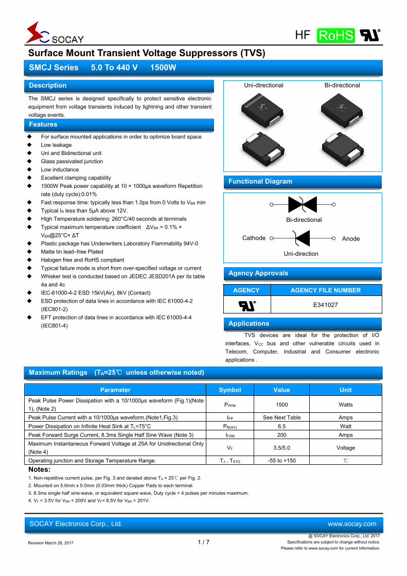
Surface Mount Transient Voltage Suppressors (TVS)
Revision March 28, 2017 1 / 7@ SOCAY Electronics Corp., Ltd. 2017
Specifications are subject to change without notice.Please refer to www.socay.com for current information.
SMCJ Series 5.0 To 440 V 1500W
SOCAY Electronics Corp., Ltd. www.socay.com
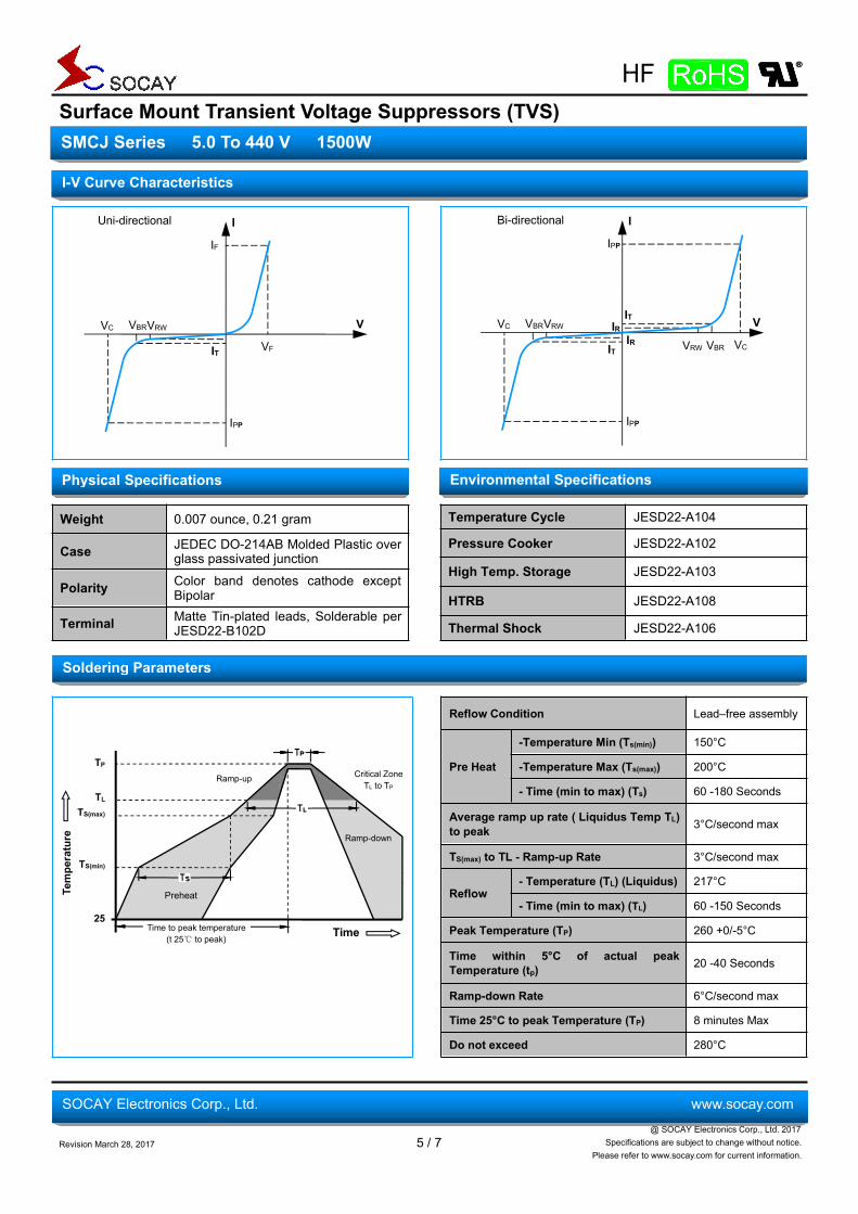
Uni-directional Bi-directional
The SMCJ series is designed specifically to protect sensitive electronicequipment from voltage transients induced by lightning and other transientvoltage events.
For surface mounted applications in order to optimize board space Low leakage Uni and Bidirectional unit Glass passivated junction Low inductance Excellent clamping capability 1500W Peak power capability at 10 × 1000µs waveform Repetition
rate (duty cycle):0.01% Fast response time: typically less than 1.0ps from 0 Volts to VBR min Typical IR less than 5μA above 12V. High Temperature soldering: 260°C/40 seconds at terminals Typical maximum temperature coefficient ΔVBR = 0.1% ×
VBR@25°C× ΔT Plastic package has Underwriters Laboratory Flammability 94V-0 Matte tin lead–free Plated Halogen free and RoHS compliant Typical failure mode is short from over-specified voltage or current Whisker test is conducted based on JEDEC JESD201A per its table
4a and 4c IEC-61000-4-2 ESD 15kV(Air), 8kV (Contact) ESD protection of data lines in accordance with IEC 61000-4-2
(IEC801-2) EFT protection of data lines in accordance with IEC 61000-4-4
(IEC801-4)
AGENCY AGENCY FILE NUMBER
E341027
TVS devices are ideal for the protection of I/Ointerfaces, VCC bus and other vulnerable circuits used inTelecom, Computer, Industrial and Consumer electronicapplications .
Parameter Symbol Value UnitPeak Pulse Power Dissipation with a 10/1000µs waveform (Fig.1)(Note1), (Note 2)
PPPM 1500 Watts
Peak Pulse Current with a 10/1000µs waveform.(Note1,Fig.3) IPP See Next Table AmpsPower Dissipation on Infinite Heat Sink at TL=75°C PM(AV) 6.5 WattPeak Forward Surge Current, 8.3ms Single Half Sine Wave (Note 3) IFSM 200 AmpsMaximum Instantaneous Forward Voltage at 25A for Unidirectional Only(Note 4)
VF 3.5/5.0 Voltage
Operating junction and Storage Temperature Range. TJ , TSTG -55 to +150 ℃
Notes:1. Non-repetitive current pulse, per Fig. 3 and derated above TA = 25℃ per Fig. 2.2. Mounted on 5.0mm x 5.0mm (0.03mm thick) Copper Pads to each terminal.3. 8.3ms single half sine-wave, or equivalent square wave, Duty cycle = 4 pulses per minutes maximum.4. VF < 3.5V for VBR < 200V and VF< 6.5V for VBR > 201V.
Functional Diagram
Agency Approvals
Applications
Maximum Ratings (TA=25℃ unless otherwise noted)
Description
Features
Bi-directional
Uni-direction
Cathode Anode
Surface Mount Transient Voltage Suppressors (TVS)
Revision March 28, 2017 2 / 7@ SOCAY Electronics Corp., Ltd. 2017
Specifications are subject to change without notice.Please refer to www.socay.com for current information.
SMCJ Series 5.0 To 440 V 1500W
SOCAY Electronics Corp., Ltd. www.socay.com
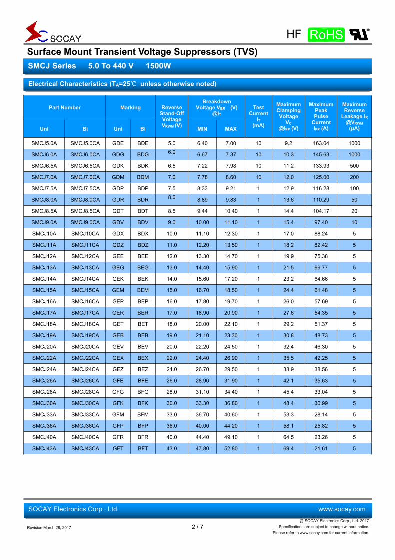
Part Number Marking ReverseStand-OffVoltageVRWM (V)
BreakdownVoltage VBR (V)
@ITTest
CurrentIT
(mA)
MaximumClampingVoltage
VC@IPP (V)
MaximumPeakPulseCurrentIPP (A)
MaximumReverseLeakage IR@VRWM(μA)Uni Bi Uni Bi MIN MAX
SMCJ5.0A SMCJ5.0CA GDE BDE 5.0 6.40 7.00 10 9.2 163.04 1000
SMCJ6.0A SMCJ6.0CA GDG BDG 6.0 6.67 7.37 10 10.3 145.63 1000
SMCJ6.5A SMCJ6.5CA GDK BDK 6.5 7.22 7.98 10 11.2 133.93 500
SMCJ7.0A SMCJ7.0CA GDM BDM 7.0 7.78 8.60 10 12.0 125.00 200
SMCJ7.5A SMCJ7.5CA GDP BDP 7.5 8.33 9.21 1 12.9 116.28 100
SMCJ8.0A SMCJ8.0CA GDR BDR 8.0 8.89 9.83 1 13.6 110.29 50
SMCJ8.5A SMCJ8.5CA GDT BDT 8.5 9.44 10.40 1 14.4 104.17 20
SMCJ9.0A SMCJ9.0CA GDV BDV 9.0 10.00 11.10 1 15.4 97.40 10
SMCJ10A SMCJ10CA GDX BDX 10.0 11.10 12.30 1 17.0 88.24 5
SMCJ11A SMCJ11CA GDZ BDZ 11.0 12.20 13.50 1 18.2 82.42 5
SMCJ12A SMCJ12CA GEE BEE 12.0 13.30 14.70 1 19.9 75.38 5
SMCJ13A SMCJ13CA GEG BEG 13.0 14.40 15.90 1 21.5 69.77 5
SMCJ14A SMCJ14CA GEK BEK 14.0 15.60 17.20 1 23.2 64.66 5
SMCJ15A SMCJ15CA GEM BEM 15.0 16.70 18.50 1 24.4 61.48 5
SMCJ16A SMCJ16CA GEP BEP 16.0 17.80 19.70 1 26.0 57.69 5
SMCJ17A SMCJ17CA GER BER 17.0 18.90 20.90 1 27.6 54.35 5
SMCJ18A SMCJ18CA GET BET 18.0 20.00 22.10 1 29.2 51.37 5
SMCJ19A SMCJ19CA GEB BEB 19.0 21.10 23.30 1 30.8 48.73 5
SMCJ20A SMCJ20CA GEV BEV 20.0 22.20 24.50 1 32.4 46.30 5
SMCJ22A SMCJ22CA GEX BEX 22.0 24.40 26.90 1 35.5 42.25 5
SMCJ24A SMCJ24CA GEZ BEZ 24.0 26.70 29.50 1 38.9 38.56 5
SMCJ26A SMCJ26CA GFE BFE 26.0 28.90 31.90 1 42.1 35.63 5
SMCJ28A SMCJ28CA GFG BFG 28.0 31.10 34.40 1 45.4 33.04 5
SMCJ30A SMCJ30CA GFK BFK 30.0 33.30 36.80 1 48.4 30.99 5
SMCJ33A SMCJ33CA GFM BFM 33.0 36.70 40.60 1 53.3 28.14 5
SMCJ36A SMCJ36CA GFP BFP 36.0 40.00 44.20 1 58.1 25.82 5
SMCJ40A SMCJ40CA GFR BFR 40.0 44.40 49.10 1 64.5 23.26 5
SMCJ43A SMCJ43CA GFT BFT 43.0 47.80 52.80 1 69.4 21.61 5
Electrical Characteristics (TA=25℃ unless otherwise noted)
Surface Mount Transient Voltage Suppressors (TVS)
Revision March 28, 2017 3 / 7@ SOCAY Electronics Corp., Ltd. 2017
Specifications are subject to change without notice.Please refer to www.socay.com for current information.
SMCJ Series 5.0 To 440 V 1500W
SOCAY Electronics Corp., Ltd. www.socay.com
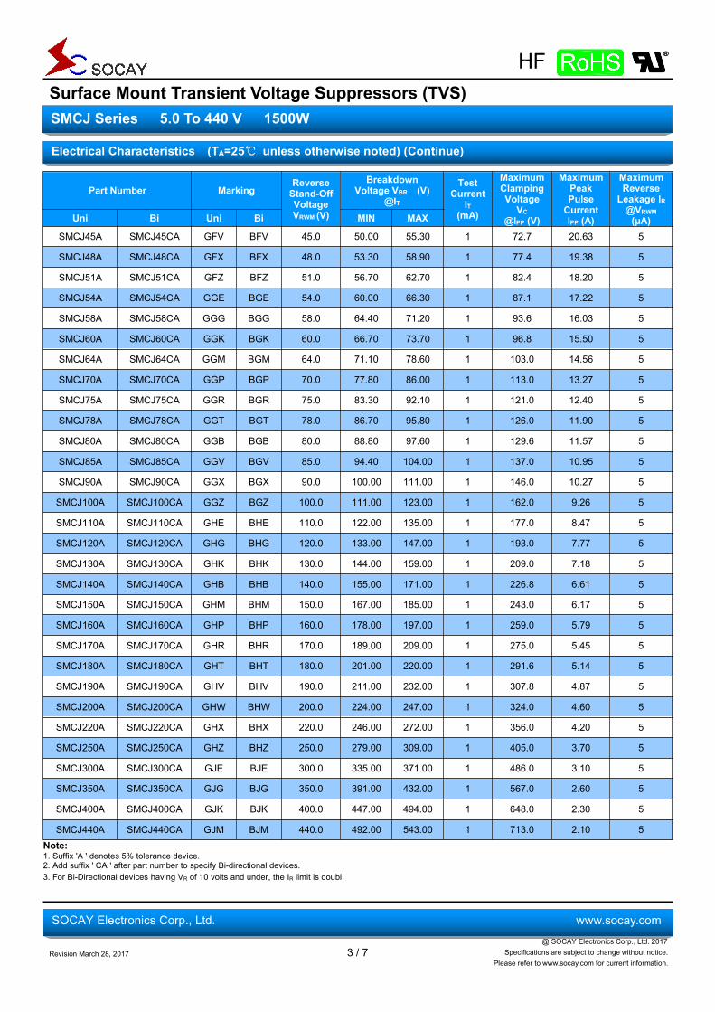
Part Number MarkingReverseStand-OffVoltageVRWM (V)
BreakdownVoltage VBR (V)
@IT
TestCurrent
IT(mA)
MaximumClampingVoltage
VC@IPP (V)
MaximumPeakPulseCurrentIPP (A)
MaximumReverseLeakage IR@VRWM(μA)Uni Bi Uni Bi MIN MAX
SMCJ45A SMCJ45CA GFV BFV 45.0 50.00 55.30 1 72.7 20.63 5
SMCJ48A SMCJ48CA GFX BFX 48.0 53.30 58.90 1 77.4 19.38 5
SMCJ51A SMCJ51CA GFZ BFZ 51.0 56.70 62.70 1 82.4 18.20 5
SMCJ54A SMCJ54CA GGE BGE 54.0 60.00 66.30 1 87.1 17.22 5
SMCJ58A SMCJ58CA GGG BGG 58.0 64.40 71.20 1 93.6 16.03 5
SMCJ60A SMCJ60CA GGK BGK 60.0 66.70 73.70 1 96.8 15.50 5
SMCJ64A SMCJ64CA GGM BGM 64.0 71.10 78.60 1 103.0 14.56 5
SMCJ70A SMCJ70CA GGP BGP 70.0 77.80 86.00 1 113.0 13.27 5
SMCJ75A SMCJ75CA GGR BGR 75.0 83.30 92.10 1 121.0 12.40 5
SMCJ78A SMCJ78CA GGT BGT 78.0 86.70 95.80 1 126.0 11.90 5
SMCJ80A SMCJ80CA GGB BGB 80.0 88.80 97.60 1 129.6 11.57 5
SMCJ85A SMCJ85CA GGV BGV 85.0 94.40 104.00 1 137.0 10.95 5
SMCJ90A SMCJ90CA GGX BGX 90.0 100.00 111.00 1 146.0 10.27 5
SMCJ100A SMCJ100CA GGZ BGZ 100.0 111.00 123.00 1 162.0 9.26 5
SMCJ110A SMCJ110CA GHE BHE 110.0 122.00 135.00 1 177.0 8.47 5
SMCJ120A SMCJ120CA GHG BHG 120.0 133.00 147.00 1 193.0 7.77 5
SMCJ130A SMCJ130CA GHK BHK 130.0 144.00 159.00 1 209.0 7.18 5
SMCJ140A SMCJ140CA GHB BHB 140.0 155.00 171.00 1 226.8 6.61 5
SMCJ150A SMCJ150CA GHM BHM 150.0 167.00 185.00 1 243.0 6.17 5
SMCJ160A SMCJ160CA GHP BHP 160.0 178.00 197.00 1 259.0 5.79 5
SMCJ170A SMCJ170CA GHR BHR 170.0 189.00 209.00 1 275.0 5.45 5
SMCJ180A SMCJ180CA GHT BHT 180.0 201.00 220.00 1 291.6 5.14 5
SMCJ190A SMCJ190CA GHV BHV 190.0 211.00 232.00 1 307.8 4.87 5
SMCJ200A SMCJ200CA GHW BHW 200.0 224.00 247.00 1 324.0 4.60 5
SMCJ220A SMCJ220CA GHX BHX 220.0 246.00 272.00 1 356.0 4.20 5
SMCJ250A SMCJ250CA GHZ BHZ 250.0 279.00 309.00 1 405.0 3.70 5
SMCJ300A SMCJ300CA GJE BJE 300.0 335.00 371.00 1 486.0 3.10 5
SMCJ350A SMCJ350CA GJG BJG 350.0 391.00 432.00 1 567.0 2.60 5
SMCJ400A SMCJ400CA GJK BJK 400.0 447.00 494.00 1 648.0 2.30 5
SMCJ440A SMCJ440CA GJM BJM 440.0 492.00 543.00 1 713.0 2.10 5Note:1. Suffix 'A ' denotes 5% tolerance device.2. Add suffix ' CA ' after part number to specify Bi-directional devices.3. For Bi-Directional devices having VR of 10 volts and under, the IR limit is doubl.
Electrical Characteristics (TA=25℃ unless otherwise noted) (Continue)
Surface Mount Transient Voltage Suppressors (TVS)
Revision March 28, 2017 4 / 7@ SOCAY Electronics Corp., Ltd. 2017
Specifications are subject to change without notice.Please refer to www.socay.com for current information.
SMCJ Series 5.0 To 440 V 1500W
SOCAY Electronics Corp., Ltd. www.socay.com
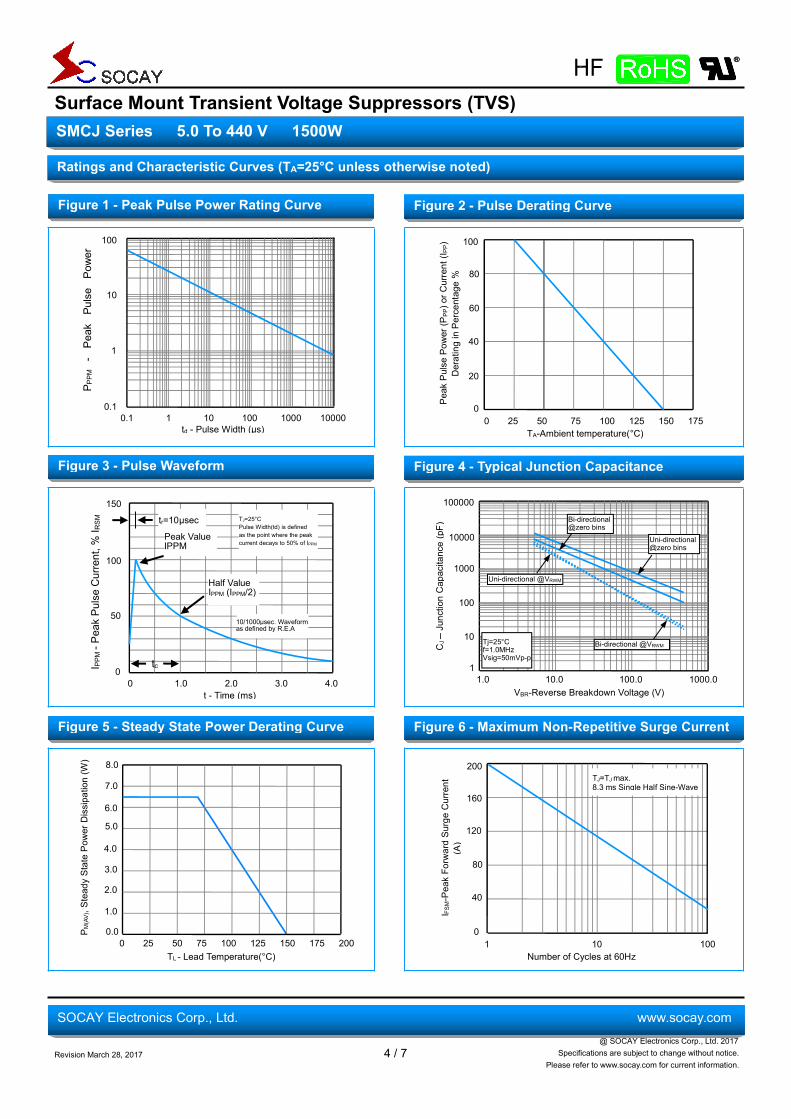
Figure 1 - Peak Pulse Power Rating Curve
Figure 3 - Pulse Waveform
Ratings and Characteristic Curves (TA=25°C unless otherwise noted)
Figure 4 - Typical Junction Capacitance
0 25 50 75 100 125 150 175
100
80
60
40
20
0
TA-Ambient temperature(°C)Pe
akPu
lsePo
wer
(PPP)orC
urrent(I P
P)DeratinginPe
rcentage
%
Figure 5 - Steady State Power Derating Curve
Figure 2 - Pulse Derating Curve
Figure 6 - Maximum Non-Repetitive Surge Current
150
100
50
0I PPM-P
eakPu
lseCurrent,%
I RSM tr=10µsec
Peak ValueIPPM
Half ValueIPPM (IPPM/2)
tc
10/1000µsec. Waveformas defined by R.E.A
0 1.0 2.0 3.0 4.0
TJ=25°CPulse Width(td) is definedas the point where the peakcurrent decays to 50% of IPPM
t - Time (ms)
td - Pulse Width (μs)
P PPM
-Pe
akPu
lse
Power
(kW)
1000
0.1
1
0.1 1 10 100 1000 10000
10
5.0
0 25 50 75 100 125 150 175 200
4.0
3.0
2.0
1.0
0.0
TL - Lead Temperature(°C)
P M(AV),S
teadyStatePo
wer
Dissipation(W
)
6.0
7.0
8.0
Number of Cycles at 60Hz
I FSM-PeakFo
rwardSu
rgeCurrent
(A)
1 10 100
120
80
40
0
160
200TJ=TJmax.8.3 ms Single Half Sine-Wave
1.0 10.0 100.0 1000.0
100000
1000
100
1
VBR-Reverse Breakdown Voltage (V)
10
10000
CJ–JunctionCapacitance(pF)
Tj=25°Cf=1.0MHzVsig=50mVp-p
Bi-directional@zero bins
Uni-directional@zero bins
Uni-directional @VRWM
Bi-directional @VRWM
Surface Mount Transient Voltage Suppressors (TVS)
Revision March 28, 2017 5 / 7@ SOCAY Electronics Corp., Ltd. 2017
Specifications are subject to change without notice.Please refer to www.socay.com for current information.
SMCJ Series 5.0 To 440 V 1500W
SOCAY Electronics Corp., Ltd. www.socay.com
Weight 0.007 ounce, 0.21 gram Temperature Cycle JESD22-A104
Pressure Cooker JESD22-A102Case JEDEC DO-214AB Molded Plastic overglass passivated junction
High Temp. Storage JESD22-A103Polarity Color band denotes cathode except
Bipolar HTRB JESD22-A108
Terminal Matte Tin-plated leads, Solderable perJESD22-B102D Thermal Shock JESD22-A106
Reflow Condition Lead–free assembly
Pre Heat
-Temperature Min (Ts(min)) 150°C
-Temperature Max (Ts(max)) 200°C
- Time (min to max) (Ts) 60 -180 Seconds
Average ramp up rate ( Liquidus Temp TL)to peak 3°C/second max
TS(max) to TL - Ramp-up Rate 3°C/second max
Reflow- Temperature (TL) (Liquidus) 217°C
- Time (min to max) (TL) 60 -150 Seconds
Peak Temperature (TP) 260 +0/-5°C
Time within 5°C of actual peakTemperature (tp) 20 -40 Seconds
Ramp-down Rate 6°C/second max
Time 25°C to peak Temperature (TP) 8 minutes Max
Do not exceed 280°C
Ramp-down
Preheat
Critical ZoneTL to TP
Time to peak temperature(t 25℃ to peak)
TP
TL
TS(max)
TS(min)
25
Temperature
Ramp-up
Time
I-V Curve Characteristics
Soldering Parameters
Physical Specifications Environmental Specifications
IF
I
VCritical
ZoneTL
to
TP
VFIT
IPP
VRW
M
VBR
RVC
Uni-directional
IPP
I
VITIR
VRW
M
VBR
RVCIT
IR
IPP
VRW
M
VBR
RVC
Bi-directional
Surface Mount Transient Voltage Suppressors (TVS)
Revision March 28, 2017 6 / 7@ SOCAY Electronics Corp., Ltd. 2017
Specifications are subject to change without notice.Please refer to www.socay.com for current information.
SMCJ Series 5.0 To 440 V 1500W
SOCAY Electronics Corp., Ltd. www.socay.com
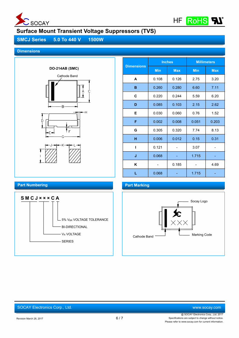
DimensionsInches Millimeters
Min Max Min Max
A 0.108 0.126 2.75 3.20
B 0.260 0.280 6.60 7.11
C 0.220 0.244 5.59 6.20
D 0.085 0.103 2.15 2.62
E 0.030 0.060 0.76 1.52
F 0.002 0.008 0.051 0.203
G 0.305 0.320 7.74 8.13
H 0.006 0.012 0.15 0.31
I 0.121 - 3.07 -
J 0.068 - 1.715 -
K - 0.185 - 4.69
L 0.068 - 1.715 -
S M C J × × × C A
5% VBR VOLTAGE TOLERANCE
BI-DIRECTIONAL
VR VOLTAGE
SERIES
Dimensions
Part Numbering Part Marking
DO-214AB (SMC)
Cathode Band
Socay Logo
Marking CodeCathode Band
Surface Mount Transient Voltage Suppressors (TVS)
Revision March 28, 2017 7 / 7@ SOCAY Electronics Corp., Ltd. 2017
Specifications are subject to change without notice.Please refer to www.socay.com for current information.
SMCJ Series 5.0 To 440 V 1500W
SOCAY Electronics Corp., Ltd. www.socay.com
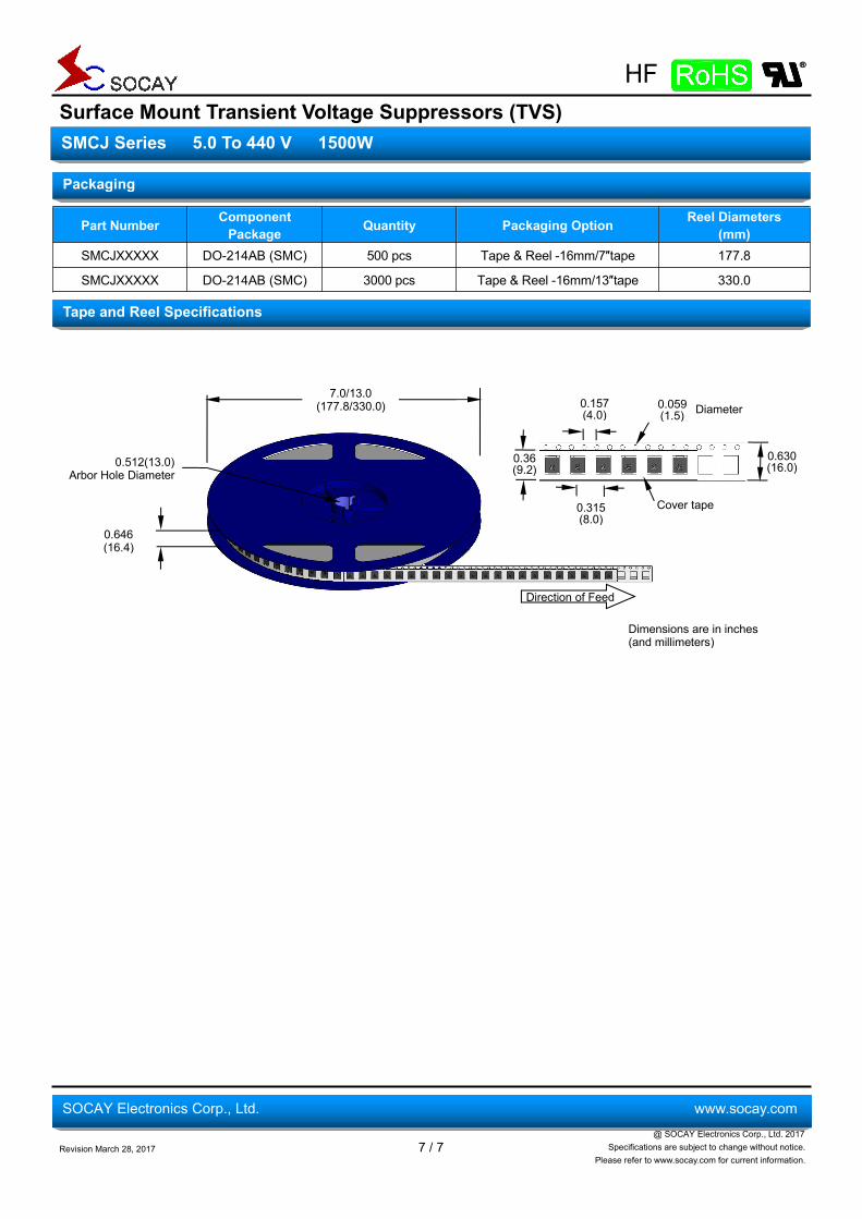
Part Number ComponentPackage Quantity Packaging Option Reel Diameters
(mm)SMCJXXXXX DO-214AB (SMC) 500 pcs Tape & Reel -16mm/7″tape 177.8
SMCJXXXXX DO-214AB (SMC) 3000 pcs Tape & Reel -16mm/13″tape 330.0
Packaging
Tape and Reel Specifications
Direction of Feed
0.646(16.4)
0.512(13.0)Arbor Hole Diameter
7.0/13.0(177.8/330.0)
Dimensions are in inches(and millimeters)
0.36(9.2)
0.157(4.0)
0.059(1.5) Diameter
0.315(8.0)
Cover tape
0.630(16.0)