Embed Size (px)
Citation preview

SAE Technical Standards Board Rules provide that: “This report is published by SAE to advance the state of technical and engineering sciences. The use of this report is entirelyvoluntary, and its applicability and suitability for any particular use, including any patent infringement arising therefrom, is the sole responsibility of the user.”
SAE reviews each technical report at least every five years at which time it may be reaffirmed, revised, or cancelled. SAE invites your written comments and suggestions.
QUESTIONS REGARDING THIS DOCUMENT: (724) 772-8512 FAX: (724) 776-0243TO PLACE A DOCUMENT ORDER; (724) 776-4970 FAX: (724) 776-0790
SAE WEB ADDRESS http://www.sae.org
Copyright 1994 Society of Automotive Engineers, Inc.All rights reserved. Printed in U.S.A.
SURFACEVEHICLE
400 Commonwealth Drive, Warrendale, PA 15096-0001RECOMMENDEDPRACTICE
Submitted for recognition as an American National Standard
J1739ISSUEDJUL94
Issued 1994-07
POTENTIAL FAILURE MODE AND EFFECTS ANALYSIS IN DESIGN (DESIGN FMEA) AND POTENTIAL FAILURE MODE AND EFFECTS ANALYSIS IN MANUFACTURING AND
ASSEMBLY PROCESSES (PROCESS FMEA REFERENCE MANUAL)
Foreword—This Document has not changed other than to put it into the new SAE Technical Standards BoardFormat.
TABLE OF CONTENTS
1 Scope ....................................................................................................................................................... 31.1 Overview................................................................................................................................................... 31.2 History ...................................................................................................................................................... 31.3 Manual Format ......................................................................................................................................... 31.4 FMEA Implementation.............................................................................................................................. 3
2 References ............................................................................................................................................... 3
3 Potential Failure Mode and Effects Analysis in Design (Design FMEA) ................................................... 33.1 Introduction............................................................................................................................................... 33.1.1 Customer Defined .................................................................................................................................... 43.1.2 Team Effort ............................................................................................................................................... 43.2 Development of a Design FMEA .............................................................................................................. 73.2.1 (1) FMEA Number .................................................................................................................................... 73.2.2 (2) System, Subsystem, or Component Name and Number ................................................................... 73.2.3 (3) Design Responsibility.......................................................................................................................... 73.2.4 (4) Prepared By ........................................................................................................................................ 73.2.5 (5) Model Year(s)/Vehicle(s) ..................................................................................................................... 73.2.6 (6) Key Date.............................................................................................................................................. 73.2.7 (7) FMEA Date ......................................................................................................................................... 73.2.8 (8) Core Team........................................................................................................................................... 73.2.9 (9) Item/Function ...................................................................................................................................... 93.2.10 (10) Potential Failure Mode ...................................................................................................................... 93.2.11 (11) Potential Effect(s) of Failure .............................................................................................................. 93.2.12 (12) Severity (S) ..................................................................................................................................... 113.2.13 (13) Classification ................................................................................................................................... 113.2.14 (14) Potential Cause(s)/Mechanism(s) of Failure ................................................................................... 133.2.15 (15) Occurrence (O) ............................................................................................................................... 133.2.16 (16) Current Design Controls.................................................................................................................. 15

SAE J1739 Issued JUL94
-2-
3.2.17 (17) Detection (D) ...................................................................................................................................153.2.18 (18) Risk Priority Number (RPN) ............................................................................................................173.2.19 (19) Recommended Action(s) ................................................................................................................. 173.2.20 (20) Responsibility (for the Recommended Action) ................................................................................ 193.2.21 (21) Actions Taken ..................................................................................................................................193.2.22 (22) Resulting RPN.................................................................................................................................193.2.23 (23) Follow-Up ........................................................................................................................................19
4 Potential Failure Mode and Effects Analysis in Manufacturing and Assembly Processes (Process FMEA)...............................................................................................................................................................21
4.1 Introduction .............................................................................................................................................214.1.1 Customer Defined...................................................................................................................................214.1.2 Team Effort .............................................................................................................................................214.2 Development of a Process FMEA........................................................................................................... 234.2.1 (1) FMEA Number...................................................................................................................................234.2.2 (2) Item ...................................................................................................................................................234.2.3 (3) Process Responsibility ...................................................................................................................... 234.2.4 (4) Prepared By ......................................................................................................................................234.2.5 (5) Model Year(s)/Vehicle(s).................................................................................................................... 234.2.6 (6) Key Date ............................................................................................................................................234.2.7 (7) FMEA Date........................................................................................................................................234.2.8 (8) Core Team.........................................................................................................................................234.2.9 (9) Process Function/Requirements ....................................................................................................... 234.2.10 (10) Potential Failure Mode..................................................................................................................... 254.2.11 (11) Potential Effect(s) of Failure............................................................................................................. 254.2.12 (12) Severity (S)......................................................................................................................................274.2.13 (13) Classification ...................................................................................................................................274.2.14 (14) Potential Cause(s)/Mechanism(s) of Failure.................................................................................... 294.2.15 (15) Occurrence (O)................................................................................................................................ 294.2.16 (16) Current Process Controls ................................................................................................................ 314.2.17 (17) Detection (D) ...................................................................................................................................314.2.18 (18) Risk Priority Number (RPN) ............................................................................................................334.2.19 (19) Recommended Action(s) ................................................................................................................. 334.2.20 (20) Responsibility (for the Recommended Action) ................................................................................ 334.2.21 (21) Actions Taken ..................................................................................................................................334.2.22 (22) Resulting RPN.................................................................................................................................354.2.23 (23) Follow-Up ........................................................................................................................................35
Appendix A Design FMEA Block Diagram Example .................................................................................................. 36
Appendix B Design FMEA Example........................................................................................................................... 37
Appendix C Process FMEA Flow Chart/Risk Assessment Example.......................................................................... 38
Appendix D Process FMEA Example .........................................................................................................................39
Appendix E Glossary..................................................................................................................................................40
Appendix F Standard Form for Design FMEA............................................................................................................41
Appendix G Standard Form for Process FMEA.......................................................................................................... 42

SAE J1739 Issued JUL94
-3-
1. Scope—General Information
1.1 Overview—This SAE Recommended Practice was jointly developed by Chrysler, Ford, and General Motorsunder the sponsorship of the United States Council for Automotive Research (USCAR).
This document introduces the topic of potential Failure Mode and Effects Analysis (FMEA) and gives generalguidance in the application of the technique. An FMEA can be described as a systemized group of activitiesintended to: (a) recognize and evaluate the potential failure of a product/process and its effects, (b) identifyactions which could eliminate or reduce the chance of the potential failure occurring, and (c) document theprocess. It is complementary to the design process of defining positively what a design must do to satisfy thecustomer.
1.2 History—Although engineers have always performed an FMEA type of analysis on their designs andmanufacturing processes, the first formal application of the FMEA discipline was an innovation of theaerospace industry in the mid-1960s.
1.3 Manual Format—For ease of use, this reference manual retains the presentation of the FMEA preparationinstructions in two distinct sections (design and process). However, having both sections in the same manualfacilitates the comparison of techniques used to develop the different types of FMEAs, as a means to moreclearly demonstrate their proper application and interrelation.
1.4 FMEA Implementation—Because of a company's commitment to continually improve its products wheneverpossible, the need for using the FMEA as a disciplined technique to identify and help eliminate potentialconcern is as important as ever. Studies of vehicle campaigns have shown that a fully implemented FMEAprogram could have prevented many of the compaigns.
Although responsibility for the "preparation" of the FMEA must, of necessity, be assigned to an individual,FMEA input should be a team effort. A team of knowledgeable individuals should be assembled: e.g.,engineers with expertise in Design, Manufacturing, Assembly, Service, Quality, and Reliability.
One of the most important factors for the successful implementation of an FMEA program is timeliness. It ismeant to be a "before-the-event" action, not an "after-the-fact" exercise. To achieve the greatest value, theFMEA must be done before a design or process failure mode has been unknowingly designed into the product.Up front time spent in doing a comprehensive FMEA well, when product/process changes can be most easilyand inexpensively implemented, will alleviate late change crises. An FMEA can reduce or eliminate the chanceof implementing a corrective change which would create an even larger concern. Properly applied, it is aninteractive process which is never ending.
2. References—There are no referenced publications specified herein.
3. Potential Failure Mode and Effects Analysis in Design (Design FMEA)
3.1 Introduction—A Design potential FMEA is an analytical technique utilized primarily by a Design ResponsibleEngineer/Team as a means to assure that, to the extent possible, potential failure modes and their associatedcauses/mechanisms have been considered and addressed. End items, along with every related system,subassembly and component, should be evaluated. In its most rigorous form, an FMEA is a summary of anengineer's and the team's thoughts (including an analysis of items that could go wrong based on experienceand past concerns) as a component, subsystem, or system is designed. This systematic approach parallels,formalizes, and documents the mental disciplines that an engineer normally goes through in any designprocess.

SAE J1739 Issued JUL94
-4-
The Design potential FMEA supports the design process in reducing the risk of failures by:
a. Aiding in the objective evaluation of design requirements and design alternatives.b. Aiding in the initial design for manufacturing and assembly requirements.c. Increasing the probability that potential failure modes and their effects on system and vehicle operation
have been considered in the design/development process.d. Providing additional information to aid in the planning of thorough and efficient design, test, and
development programs.e. Developing a list of potential failure modes ranked according to their effect on the "customer," thus
establishing a priority system for design improvements and development testing.f. Providing an open issue format for recommending and tracking risk reducing actions.g. Providing future reference to aid in analyzing field concerns, evaluating design changes and
developing advanced designs.
3.1.1 CUSTOMER DEFINED—The definition of "CUSTOMER" for a Design potential FMEA is not only the "ENDUSER," but also the design responsible engineers/teams of the vehicle or higher level assemblies, and/or themanufacturing process responsible engineers in activities such as Manufacturing, Assembly, and Service.
When fully implemented, the FMEA discipline requires a Design FMEA for all new parts, changed parts, andcarryover parts in new applications or environments. It is initiated by an engineer from the responsibledesign activity, which for a proprietary design may be the supplier.
3.1.2 TEAM EFFORT—During the initial Design potential FMEA process, the responsible engineer is expected todirectly and actively involve representatives from all affected areas. These areas should include, but are notlimited to: assembly, manufacturing, materials, quality, service, and suppliers, as well as the design arearesponsible for the next assembly. The FMEA should be a catalyst to stimulate the interchange of ideasbetween the functions affected and thus promote a team approach. In addition, for any (internal/external)supplier designed items, the responsible design engineer should be consulted.
The Design FMEA is a living document and should be initiated before or at design concept finalization, becontinually updated as changes occur or additional information is obtained throughout the phases of productdevelopment, and be fundamentally completed before the production drawings are released for tooling.
Considering that manufacturing/assembly needs have been incorporated, the Design FMEA addresses thedesign intent and assumes the design will be manufactured/assembled to this intent. Potential failure modesand/or causes/mechanisms which can occur during the manufacturing or assembly process need not, butmay be included in a Design FMEA. When not included, their identification, effect and control are covered bythe Process FMEA.
The Design FMEA does not rely on process controls to overcome potential weaknesses in the design, but itdoes take the technical/physical limits of a manufacturing/assembly process into consideration, e.g.:
a. Necessary mold draftsb. Limited surface finishc. Assembling space/access for toolingd. Limited hardenability of steelse. Process capability/performance

SAE J1739 Issued JUL94
-5-
THIS PAGE IS LEFT BLANK INTENTIONALLY

SAE J1739 Issued JUL94
-6-
FIGURE 1—DESIGN FMEA FORM

SAE J1739 Issued JUL94
-7-
3.2 Development of a Design FMEA—The design responsible engineer has at his or her disposal a number ofdocuments that will be useful in preparing the Design potential FMEA. The process begins by developing alisting of what the design is expected to do, and what it is expected not to do, i.e., the design intent. Customerwants and needs, as may be determined from sources such as Quality Function Deployment (QFD), VehicleRequirements Documents, known product requirements and/or manufacturing/assembly requirements shouldbe incorporated. The better the definition of the desired characteristics, the easier it is to identify potentialfailure modes for corrective action.
A Design FMEA should begin with a block diagram for the system, subsystem, and/or component beinganalyzed. An example block diagram is shown in Appendix A. The block diagram can also indicate the flow ofinformation, energy, force, fluid, etc. The object is to understand the deliverables (input) to the block, theprocess (function) performed in the block, and the deliverables (output) from the block.
The diagram illustrates the primary relationship between the items covered in the analysis and establishes alogical order to the analysis. Copies of the diagrams used in FMEA preparation should accompany the FMEA.
In order to facilitate documentation of the analysis of potential failures and their consequences, a form hasbeen designed and is in Appendix F. (See Figure F1.)
Application of the form is described as follows: Points are numbered according to the numbers encircled on thereference Figures. An example of a completed form is contained in Appendix B. (See Figure B1.)
3.2.1 (1) FMEA NUMBER—Enter the FMEA document number, which may be used for tracking. (See Figure 1.)
3.2.2 (2) SYSTEM, SUBSYSTEM, OR COMPONENT NAME AND NUMBER—Indicate the appropriate level of analysis andenter the name and number of the system, subsystem, or component being analyzed. (See Figure 1.)
3.2.3 (3) DESIGN RESPONSIBILITY—Enter the OEM, department, and group. Also include the supplier name ifknown. (See Figure 1.)
3.2.4 (4) PREPARED BY—Enter the name, telephone number, and company of the engineer responsible forpreparing the FMEA. (See Figure 1.)
3.2.5 (5) MODEL YEAR(S)/VEHICLE(S)—Enter the intended model year(s) and vehicle line(s) that will utilize and/or beaffected by the design being analyzed (if known). (See Figure 1.)
3.2.6 (6) KEY DATE—Enter the initial FMEA due date, which should not exceed the scheduled production designrelease date. (See Figure 1.)
3.2.7 (7) FMEA DATE—Enter the date the original FMEA was compiled, and the latest revision date. (See Figure1.)
3.2.8 (8) CORE TEAM—List the names of the responsible individuals and departments which have the authority toidentify and/or perform tasks. (It is recommended that all team members names, departments, telephonenumbers, addresses, etc., be included on a distribution list). (See Figure 1.)

SAE J1739 Issued JUL94
-8-
FIGURE 2—DESIGN FMEA FORM

SAE J1739 Issued JUL94
-9-
3.2.9 (9) ITEM/FUNCTION—Enter the name and number of the item being analyzed. Use the nomenclature andshow the design level as indicated on the engineering drawing. Prior to initial release, experimental numbersshould be used. (See Figure 2.)
Enter, as concisely as possible, the function of the item being analyzed to meet the design intent. Includeinformation regarding the environment in which this system operates (e.g., define temperature, pressure,humidity ranges). If the item has more than one function with different potential modes of failure, list all thefunctions separately.
3.2.10 (10) POTENTIAL FAILURE MODE—Potential Failure Mode is defined as the manner in which a component,subsystem, or system could potentially fail to meet the design intent. The potential failure mode may also bethe cause of a potential failure mode in a higher level subsystem, or system, or be the effect of one in a lowerlevel component. (See Figure 2.)
List each potential failure mode for the particular item and item function. The assumption is made that thefailure could occur, but may not necessarily occur. A recommended starting point is a review of past things-gone-wrong, concerns, reports, and group brainstorming.
Potential failure modes that could only occur under certain operating conditions (i.e., hot, cold, dry, dusty,etc.) and under certain usage conditions (i.e., above average mileage, rough terrain, only city driving, etc.)should be considered.
Typical failure modes could be, but are not limited to:
NOTE— Potential failure modes should be described in "physical" or technical terms, not as a symptomnoticeable by the customer.
3.2.11 (11) POTENTIAL EFFECT(S) OF FAILURE—Potential Effects of Failure are defined as the effects of the failuremode on the function, as perceived by the customer. (See Figure 2.)
Describe the effects of the failure in terms of what the customer might notice or experience, rememberingthat the customer may be an internal customer as well as the ultimate end user. State clearly if the functioncould impact safety or noncompliance to regulations. The effects should always be stated in terms of thespecific system, subsystem, or component being analyzed. Remember that a hierarchical relationship existsbetween the component, subsystem, and system levels. For example, a part could fracture, which maycause the assembly to vibrate, resulting in an intermittent system operation. The intermittent systemoperation could cause performance to degrade, and ultimately lead to customer dissatisfaction. The intent isto forecast the failure effects to the Team's level of knowledge.
Typical failure effects could be, but are not limited to:
Cracked Sticking
Deformed Short circuited (electrical)
Loosened Oxidized
Leaking Fractured
Noise Rough
Erratic Operation Inoperative
Poor Appearance Unpleasant Odor
Unstable Operation Impaired
Intermittent Operation

SAE J1739 Issued JUL94
-10-
FIGURE 3—DESIGN FMEA FORM

SAE J1739 Issued JUL94
-11-
3.2.12 (12) SEVERITY(S)—Severity is an assessment of the seriousness of the effect (listed in the previous column)of the potential failure mode to the next component, subsystem, system, or customer if it occurs. Severityapplies to the effect only. A reduction in Severity Ranking index can be effected only through a designchange. Severity should be estimated on a "1" to "10" scale. (See Figure 3.)
3.2.12.1 Suggested Evaluation Criteria—The team should agree on an evaluation criteria and ranking system,which is consistent, even if modified for individual product analysis. (See Table 1.)
3.2.13 (13) CLASSIFICATION—This column may be used to classify any special product characteristics (e.g., critical,key, major, significant) for components, subsystems, or systems that may require additional process controls.(See Figure 3.)
Any item deemed to require special process controls should be identified on the Design FMEA form with theappropriate character or symbol in the Classification column and should be addressed in the RecommendedActions column.
Each special product characteristic should have the special process controls identified in the Process FMEA.
TABLE 1—SUGGESTED SEVERITY EVALUATION CRITERIA
Effect Criteria: Severity of Effect Ranking
Hazardous-withoutwarning
Very high severity ranking when a potential failure mode affects safe vehicleoperation and/or involves noncompliance with government regulationwithout warning.
10
Hazardous-with warning
Very high severity ranking when a potential failure mode affects safe vehicleoperation and/or involves noncompliance with government regulation withwarning.
9
Very High Vehicle/item inoperable, with loss of primary function. 8
High Vehicle/item operable, but at reduced level of performance. Customerdissatisfied.
7
Moderate Vehicle/item operable, but Comfort/Convenience item(s) inoperable.Customer experiences discomfort.
6
Low Vehicle/item operable, but Comfort/Convenience item(s) operable atreduced level of performance. Customer experiences some dissatisfaction.
5
Very Low Fit & Finish/Squeak & Rattle item does not conform. Defect noticed by mostcustomers.
4
Minor Fit & Finish/Squeak & Rattle item does not conform. Defect noticed byaverage customer.
3
Very Minor Fit & Finish/Squeak & Rattle item does not conform. Defect noticed bydiscriminating customer.
2
None No Effect. 1

SAE J1739 Issued JUL94
-12-
FIGURE 4—DESIGN FMEA FORM

SAE J1739 Issued JUL94
-13-
3.2.14 (14) POTENTIAL CAUSE(S)/MECHANISM(S) OF FAILURE—Potential Cause of Failure is defined as an indication ofa design weakness, the consequence of which is the failure mode. (See Figure 4.)
List, to the extent possible, every conceivable failure cause and/or failure mechanism for each failure mode.The cause/mechanism should be listed as concisely and completely as possible so that remedial efforts canbe aimed at pertinent causes.
Typical failure causes may include, but are not limited to:
Incorrect Material SpecifiedInadequate Design Life AssumptionOver-stressingInsufficient Lubrication CapabilityInadequate Maintenance InstructionsPoor Environment ProtectionIncorrect Algorithm
Typical failure mechanisms may include, but are not limited to:
YieldFatigueMaterial InstabilityCreepWearCorrosion
3.2.15 (15) OCCURRENCE (O)—Occurrence is the likelihood that a specific cause/mechanism (listed in the previouscolumn) will occur. The likelihood of occurrence ranking number has a meaning rather than a value.Removing or controlling one or more of the causes/mechanisms of the failure mode through a design changeis the only way a reduction in the occurrence can be effected. (See Figure 4.)
Estimate the likelihood of occurrence of potential failure cause/mechanism on a "1" to "10" scale. Indetermining this estimate, questions such as the following should be considered:
a. What is the service history/field experience with similar components or subsystems?b. Is component carryover or similar to a previous level component or subsystem?c. How significant are changes from a previous level component or subsystem?d. Is component radically different from a previous level component?e. Is component completely new?f. Has the component application changed?g. What are the environmental changes?h. Has an engineering analysis been used to estimate the expected comparable occurrence rate for the
application?
A consistent occurrence ranking system should be used to ensure continuity. The "Design Life PossibleFailure Rates" are based on the number of failures which are anticipated during the design life of thecomponent, subsystem, or system. The occurrence ranking number is related to the rating scale and doesnot reflect the actual likelihood of occurrence.

SAE J1739 Issued JUL94
-14-
FIGURE 5—DESIGN FMEA FORM

SAE J1739 Issued JUL94
-15-
3.2.15.1 Suggested Evaluation Criteria—The team should agree on an evaluation criteria and ranking system,which is consistent, even if modified for individual product analysis. (See Table 2.)
3.2.16 (16) CURRENT DESIGN CONTROLS—List the prevention, design validation/verification (DV), or other activitieswhich will assure the design adequacy for the failure mode and/or cause/mechanism under consideration.Current controls (e.g., road testing, design reviews, fail/safe (pressure relief valve), mathematical studies, rig/lab testing, feasibility review, prototype tests, fleet testing) are those that have been or are being used withthe same or similar designs. (See Figure 5.)
There are three types of Design Controls/features to consider, those that:
1. Prevent the cause/mechanism or failure mode/effect from occurring, or reduce their rate of occurrence,2. Detect the cause/mechanism and lead to corrective actions, and3. Detect the failure mode.
The preferred approach is to first use type (1) controls if possible; second, use the type (2) controls; andthird, use the type (3) controls. The initial occurrence rankings will be affected by the type (1) controlsprovided they are integrated as part of the design intent. The initial detection rankings will be based on thetype (2) or type (3) current controls, provided the prototypes and models being used are representative ofdesign intent.
3.2.17 (17) DETECTION (D)—Detection is an assessment of the ability of the proposed type (2) current designcontrols, listed in column 16, to detect a potential cause/mechanism (design weakness), or the ability of theproposed type (3) current design controls to detect the subsequent failure mode, before the component,subsystem, or system is released for production. (See Figure 5.) In order to achieve a lower ranking,generally the planned design control (e.g., preventative, validation, and/or verification activities) has to beimproved.
TABLE 2—SUGGESTED OCCURRENCE EVALUATION CRITERIA
Probability of Failure Possible Failure Rates Ranking
Very High: Failure is almost inevitable ≥ 1 in 2 10
1 in 3 9
High: Repeated failures 1 in 8 8
1 in 20 7
Moderate: Occasional failures 1 in 80 6
1 in 400 5
1 in 2000 4
Low: Relatively few failures 1 in 15 000 3
1 in 150 000 2
Remote: Failure is unlikely ≤ 1 in 1 500 000 1

SAE J1739 Issued JUL94
-16-
FIGURE 6—DESIGN FMEA FORM

SAE J1739 Issued JUL94
-17-
3.2.17.1 Suggested Evaluation Criteria—The team should agree on an evaluation criteria and ranking system,which is consistent, even if modified for individual product analysis. (See Table 3.)
3.2.18 (18) RISK PRIORITY NUMBER (RPN)—The Risk Priority Number is the product of the Severity (S), Occurrence(O), and Detection (D) ranking. (See Figure 6 and Equation 1.)
(Eq. 1)
The Risk Priority Number, as the product S x O x D, is a measure of design risk. This value should be usedto rank order the concerns in the design (e.g., in Pareto fashion). The RPN will be between "1" and "1000".For high RPNs, the team must undertake efforts to reduce this calculated risk through corrective action(s). Ingeneral practice, regardless of the resultant RPN, special attention should be given when severity is high.
3.2.19 (19) RECOMMENDED ACTION(S)—When the failure modes have been rank ordered by RPN, corrective actionshould be first directed at the highest ranked concerns and critical items. The intent of any recommendedaction is to reduce any one or all of the occurrence, severity, and/or detection rankings. An increase indesign validation/verification actions will result in a reduction in the detection ranking only. A reduction in theoccurrence ranking can be effected only by removing or controlling one or more of the causes/mechanismsof the failure mode through a design revision. Only a design revision can bring about a reduction in theseverity ranking. Actions such as the following should be considered, but are not limited to: (See Figure 6.)
a. Design of experiments (particularly when multiple or interactive causes are present)b. Revised Test Planc. Revised Designd. Revised Material Specification
If no actions are recommended for a specific cause, indicate this by entering a "NONE" in this column.
TABLE 3—SUGGESTED DETECTION EVALUATION CRITERIA
Detection Criteria: Likelihood of Detection by Design Control Ranking
AbsoluteUncertainty
Design Control will not and/or can not detect a potential cause/mechanismand subsequent failure mode; or there is no Design Control.
10
Very Remote Very remote chance the Design Control will detect a potentialcause/mechanism and subsequent failure mode.
9
Remote Remote chance the Design Control will detect a potential cause/mechanismand subsequent failure mode.
8
Very Low Very Low chance the Design Control will detect a potential cause/mechanismand subsequent failure mode.
7
Low Low chance the Design Control will detect a potential cause/mechanism andsubsequent failure mode.
6
Moderate Moderate chance the Design Control will detect a potential cause/mechanismand subsequent failure mode.
5
ModeratelyHigh
Moderately high chance the Design Control will detect a potential cause/mechanism and subsequent failure mode.
4
High High chance the Design Control will detect a potential cause/mechanism andsubsequent failure mode.
3
Very High Very High chance the Design Control will detect a potential cause/mechanismand subsequent failure mode.
2
Almost Certain Design Control will almost certainly detect a potential cause/mechanism andsubsequent failure mode.
1

SAE J1739 Issued JUL94
-18-
FIGURE 7—DESIGN FMEA FORM
SAE J1739 Issued JUL94
-19-
3.2.20 (20) RESPONSIBILITY (FOR THE RECOMMENDED ACTION)—Enter the Organization and individual responsiblefor the recommended action and the target completion date. (See Figure 7.)
3.2.21 (21) ACTIONS TAKEN—After an action has been implemented, enter a brief description of the actual actionand effective date. (See Figure 7.)
3.2.22 (22) RESULTING RPN—After the corrective action has been identified, estimate and record the resultingseverity, occurrence, and detection rankings. Calculate and record the resulting RPN. If no actions aretaken, leave the "Resulting RPN" and related ranking columns blank. (See Figure 7.)
All Resulting RPNs should be reviewed and if further action is considered necessary, repeat 3.2.19 through3.2.22.
3.2.23 FOLLOW-UP—The design responsible engineer is responsible for assuring that all actions recommendedhave been implemented or adequately addressed. The FMEA is a living document and should always reflectthe latest design level, as well as the latest relevant actions, including those occurring after start ofproduction.
The design responsible engineer has several means of assuring that concerns are identified and thatrecommended actions are implemented. They include, but are not limited to the following:
a. Assuring design requirements are achievedb. Review of engineering drawings and specificationsc. Confirmation of incorporation to assembly/manufacturing documentationd. Review of Process FMEAs and Control Plans

SAE J1739 Issued JUL94
-20-
THIS PAGE IS LEFT BLANK INTENTIONALLY

SAE J1739 Issued JUL94
-21-
4. Potential Failure Mode and Effects Analysis in Manufacturing and Assembly Processes (ProcessFMEA)
4.1 Introduction—A Process potential FMEA is an analytical technique utilized by a Manufacturing ResponsibleEngineer/Team as a means to assure that, to the extent possible, potential failure modes and their associatedcauses/mechanisms have been considered and addressed. In its most rigorous form, an FMEA is a summaryof the engineer's/team's thoughts (including an analysis of items that could go wrong based on experience andpast concerns) as a process is developed. This systematic approach parallels and formalizes the mentaldiscipline that an engineer normally goes through in any manufacturing planning process.
The Process potential FMEA:
a. Identifies potential product related process failure modes.b. Assesses the potential customer effects of the failures.c. Identifies the potential manufacturing or assembly process causes and identifies process variables on
which to focus controls for occurrence reduction or detection of the failure conditions.d. Develops a ranked list of potential failure modes, thus establishing a priority system for corrective
action considerations.e. Documents the results of the manufacturing or assembly process.
4.1.1 CUSTOMER DEFINED—The definition of "CUSTOMER" for a Process potential FMEA should normally be seenas the "END USER." However, customer can also be a subsequent or downstream manufacturing orassembly operation, as well as a service operation.
When fully implemented, the FMEA discipline requires a Process FMEA for all new parts/processes,changed parts/processes, and carryover parts/processes in new applications or environments. It is initiatedby an engineer from the responsible process engineering department.
4.1.2 TEAM EFFORT—During the initial Process potential FMEA process, the responsible engineer is expected todirectly and actively involve representatives from all affected areas. These areas should include, but are notlimited to, design, assembly, manufacturing, materials, quality, service, and suppliers, as well as the arearesponsible for the next assembly. The FMEA should be a catalyst to stimulate the interchange of ideasbetween the areas affected and thus promote a team approach.
The Process FMEA is a living document and should be initiated before or at the feasibility stage, prior totooling for production, and take into account all manufacturing operations, from individual components toassemblies. Early review and analysis of new or revised processes is promoted to anticipate, resolve, ormonitor potential process concerns during the manufacturing planning stages of a new model or componentprogram.
The Process FMEA assumes the product as designed will meet the design intent. Potential failure modeswhich can occur because of a design weakness need not, but may be included in a Process FMEA. Theireffect and avoidance is covered by the Design FMEA.
The Process FMEA does not rely on product design changes to overcome weaknesses in the process, butdoes take into consideration a product's design characteristics relative to the planned manufacturing orassembly process to assure that, to the extent possible, the resultant product meets customer needs andexpectations.
The FMEA discipline will also assist in developing new machines or equipment. The methodology is thesame, however, the machine or equipment being designed is considered the product. When potential failuremodes are identified, corrective action can be initiated to eliminate them or continuously reduce theirpotential for occurrence.

SAE J1739 Issued JUL94
-22-
FIGURE 8—PROCESS FMEA FORM

SAE J1739 Issued JUL94
-23-
4.2 Development of a Process FMEA—A Process FMEA should begin with a flow chart/risk assessment (seeAppendix C) of the general process. This flow chart should identify the product/process characteristicsassociated with each operation. Identification of some product effects from the corresponding Design FMEA,should be included, if available. Copies of the flow chart/risk assessment used in FMEA preparation shouldaccompany the FMEA.
In order to facilitate documentation of the analysis of potential failures and their consequences, a ProcessFMEA form was developed and is in Appendix G. (See Figure G1.)
Application of the form is described as follows. Points are numbered according to the numbers encircled on thereference Figures. An example of a completed form is contained in Appendix D. (See Figure D1.)
4.2.1 (1) FMEA NUMBER—Enter the FMEA document number, which may be used for tracking. (See Figure 8.)
4.2.2 (2) ITEM—Enter the name and number of the system, subsystem, or component, for which the process isbeing analyzed. (See Figure 8.)
4.2.3 (3) PROCESS RESPONSIBILITY—Enter the OEM, department, and group. Also include the supplier name ifknown. (See Figure 8.)
4.2.4 (4) PREPARED BY—Enter the name, telephone number, and company of the engineer responsible forpreparing the FMEA. (See Figure 8.)
4.2.5 (5) MODEL YEAR(S)/VEHICLE(S)—Enter the intended model year(s) and vehicle line(s) that will utilize and/or beaffected by the design/process being analyzed (if known). (See Figure 8.)
4.2.6 (6) KEY DATE—Enter the initial FMEA due date, which should not exceed the scheduled start of productiondate. (See Figure 8.)
4.2.7 (7) FMEA DATE—Enter the date the original FMEA was complied, and the latest revision date. (See Figure8.)
4.2.8 (8) CORE TEAM—List the names of the responsible individuals and departments which have the authority toidentify and/or perform tasks. (It is recommended that all team members names, departments, telephonenumbers, addresses, etc., be included on a distribution list.) (See Figure 8.)
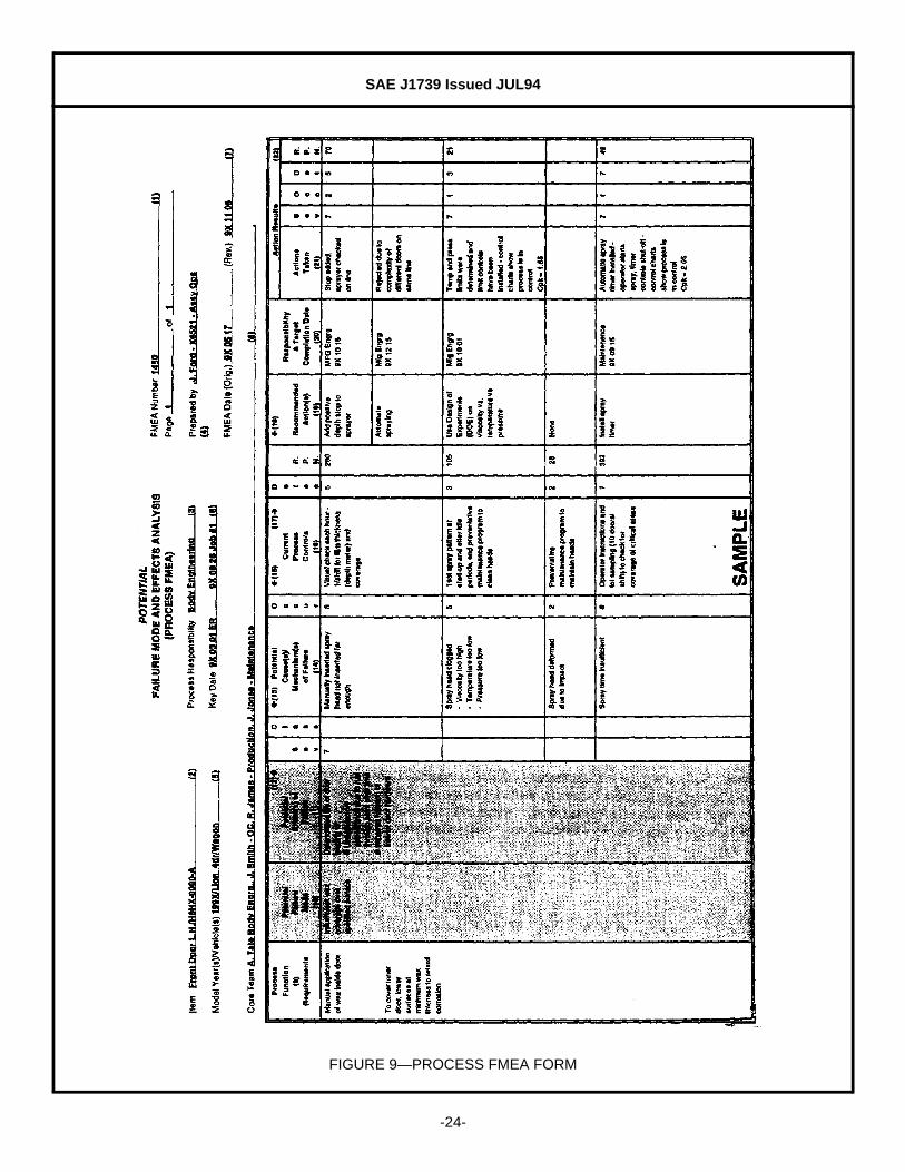
4.2.9 (9) PROCESS FUNCTION/REQUIREMENTS—Enter a simple description of the process or operation beinganalyzed (e.g., turning, drilling, tapping, welding, assembling). Indicate as concisely as possible the purposeof the process or operation being analyzed. Where the process involves numerous operations (e.g.,assembling) with different potential modes of failure, it may be desirable to list the operations as separateprocesses. (See Figure 9.)
SAE J1739 Issued JUL94
-24-
FIGURE 9—PROCESS FMEA FORM

SAE J1739 Issued JUL94
-25-
4.2.10 (10) POTENTIAL FAILURE MODE—Potential Failure Mode is defined as the manner in which the process couldpotentially fail to meet the process requirements and/or design intent. It is a description of thenonconformance at that specific operation. It can be a cause associated with a potential failure mode in asubsequent (downstream) operation or an effect associated with a potential failure in a previous (upstream)operation. However, in preparation of the FMEA, the assumption should be made that the incoming part(s)/material(s) are correct. (See Figure 9.)
List each potential failure mode for the particular operation in terms of a component, subsystem, system, orprocess characteristic. The assumption is made that the failure could occur, but may not necessarily occur.The process engineer/team should be able to pose and answer the following questions:
a. How can the process/part fail to meet specifications?b. Regardless of engineering specifications, what would a customer (end user, subsequent operations, or
service) consider objectionable?
A comparison of similar processes and a review of customer (end user and subsequent operation) claimsrelating to similar components is a recommended starting point. In addition a knowledge of the purpose ofthe design is necessary. Typical failure modes could be, but are not limited to:
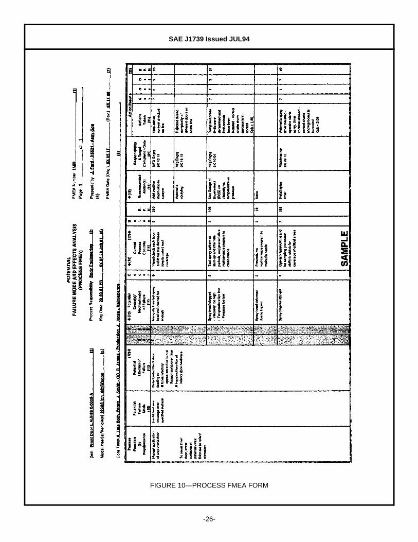
4.2.11 (11) POTENTIAL EFFECT(S) OF FAILURE—Potential Effects of Failure are defined as the effects of the failuremode on the customer(s). The customer(s) in this context could be the next operation, subsequentoperations or locations, the dealer, and/or the vehicle owner. Each must be considered when assessing thepotential effect of a failure. (See Figure 9.)
Describe the effects of the failure in terms of what the customer(s) might notice or experience. For the EndUser, the effects should always be stated in terms of product or system performance, such as:
If the customer is the next operation or subsequent operation(s)/location(s), the effects should be stated interms of process/operation performance, such as:
Bent
Binding Burred
Handling Damage Cracked
Deformed Dirty
Improper Set-up Grounded
Open Circuited Short Circuited
Tool Worn
Noise
Rough Erratic Operation
Excessive Effort Required Inoperative
Unpleasant Odor Unstable
Operation Impaired Draft
Intermittent Operation Poor Appearance
Vehicle Control Impaired
Can not fasten Does not fit
Can not bore/tap Does not connect
Can not mount Does not match
Can not face Damages equipment
Endangers operator
SAE J1739 Issued JUL94
-26-
FIGURE 10—PROCESS FMEA FORM

SAE J1739 Issued JUL94
-27-
4.2.12 (12) SEVERITY (S)—Severity is an assessment of the seriousness of the effect (listed in the previous column)of the potential failure mode to the customer. Severity applies to the effect only. If the customer affected bya failure mode is the assembly plant or the product user, assessing the severity may lie outside theimmediate process engineer's/team's field of experience or knowledge. In these cases, the design FMEA,design engineer, and/or subsequent manufacturing or assembly plant process engineer should be consulted.Severity should be estimated on a "1" to "10" scale. (See Figure 10.)
4.2.12.1 Suggested Evaluation Criteria—The team should agree on an evaluation criteria and ranking system,which is consistent, even if modified for individual process analysis. (See Table 4.)
4.2.13 (13) CLASSIFICATION—This column may be used to classify any special process characteristics (e.g., critical,key, major, significant) for components, subsystems, or systems that may require additional process controls.If a classification is identified in the Process FMEA, notify the design responsible engineer since this mayaffect the engineering documents concerning control item identification. (See Figure 10.)
TABLE 4—SUGGESTED SEVERITY EVALUATION CRITERIA
Effect Criteria: Severity of Effect Ranking
Hazardous-withoutwarning
May endanger machine or assembly operator. Very high severity rankingwhen a potential failure mode affects safe vehicle operation and/or involvesnoncompliance with government regulation. Failure will occur withoutwarning.
10
Hazardous-with warning
May endanger machine or assembly operator. Very high severity rankingwhen a potential failure mode affects safe vehicle operation and/or involvesnoncompliance with government regulation. Failure will occur with warning.
9
Very High Major disruption to production line. 100% of product may have to bescrapped. Vehicle/item inoperable, loss of primary function. Customer verydissatisfied.
8
High Minor disruption to production line. Product may have to be sorted and aportion (less than 100%) scrapped. Vehicle operable, but at a reduced levelof performance. Customer dissatisfied.
7
Moderate Minor disruption to production line. A portion (less than 100%) of theproduct may have to be scrapped (no sorting). Vehicle/item operable, butsome Comfort/Convenience item(s) inoperable. Customer experiencesdiscomfort.
6
Low Minor disruption to production line. 100% of product may have to bereworked. Vehicle/item operable, but some Comfort/Convenience item(s)operable at reduced level of performance. Customer experiences somedissatisfaction.
5
Very Low Minor disruption to production line. The product may have to be sorted anda portion (less than 100%) reworked. Fit & Finish/Squeak & Rattle itemdoes not conform. Defect noticed by most customers.
4
Minor Minor disruption to production line. A portion (less than 100%) of theproduct may have to be reworked on-line but out-of-station. Fit & Finish/Squeak & Rattle does not conform. Defect noticed by averagecustomers.
3
Very Minor Minor disruption to production line. A portion (less than 100%) of theproduct may have to be reworked on-line but in-station. Fit & Finish/Squeak& Rattle item does not conform. Defect noticed by discriminatingcustomers.
2
None No effect.

SAE J1739 Issued JUL94
-28-
FIGURE 11—PROCESS FMEA FORM

SAE J1739 Issued JUL94
-29-
4.2.14 (14) POTENTIAL CAUSE(S)/MECHANISM(S) OF FAILURE—Potential Cause of Failure is defined as how the failurecould occur, described in terms of something that can be corrected or can be controlled. (See Figure 11.)
List, to the extent possible, every conceivable failure cause assignable to each potential failure mode. If acause is exclusive to the failure mode, i.e., if correcting the cause has a direct impact on the failure mode,then this portion of the FMEA thought process is completed. Many causes, however, are not mutuallyexclusive, and to correct or control the cause, a design of experiments, for example, may be considered todetermine which root causes are the major contributors and which can be most easily controlled. Thecauses should be described so that remedial efforts can be aimed at those causes which are pertinent.Typical failure causes may include, but are not limited to:
Only specific errors or malfunctions (e.g., operator fails to install seal) should be listed; ambiguous phrases(e.g., operator error, machine malfunction) should not be used.
4.2.15 (15) OCCURRENCE (O)—Occurrence is how frequently the specific failure cause/mechanism is projected tooccur (listed in the previous column). The occurrence ranking number has a meaning rather than a value.
Estimate the likelihood of the occurrence on a "1" to "10" scale. Only occurrences resulting in the failuremode should be considered for this ranking; failure detecting measures are not considered here. (SeeFigure 11.)
The following occurrence ranking system should be used to ensure consistency. The "Possible FailureRates" are based on the number of failures which are anticipated during the process execution.
If available from a similar process, statistical data should be used to determine the occurrence ranking. In allother cases, a subjective assessment can be made by utilizing the word descriptions in the left column of thetable, along with any historical data available for similar processes.
4.2.15.1 Suggested Evaluation Criteria—The team should agree on an evaluation criteria and ranking system,which is consistent, even if modified for individual process analysis. (See Table 5.)
Improper torque - over, under Improper weld - current, time, pressure
Inaccurate gauging Improper heat treat - time, temperature
Inadequate gating/venting Inadequate or no lubrication
Part missing or mislocated
TABLE 5—SUGGESTED OCCURRENCE EVALUATION CRITERIA
Probability of Failure PossibleFailure Rates
Cpk Ranking
Very High: Failure is almost inevitable. ≥ 1 in 2 <0.33 10
1 in 3 ≥0.33 9
High: Generally associated with processes similar to previousprocesses that have often failed.
1 in 8 ≥0.51 8
1 in 20 ≥0.67 7
Moderate: Generally associated with processes similar to previousprocesses which have experienced occasional failures, but not inmajor proportions.
1 in 80 ≥0.83 6
1 in 400 ≥1.00 5
1 in 2000 ≥1.17 4
Low: Isolated failures associated with similar processes. 1 in 15 000 ≥1.33 3
Very Low: Only isolated failures associated with almost identicalprocesses.
1 in 150 000 ≥1.50 2
Remote: Failure is unlikely. No failures ever associated withalmost identical processes.
≤ 1 in 1 500 000 ≥1.67 1
SAE J1739 Issued JUL94
-30-
FIGURE 12—PROCESS FMEA FORM
SAE J1739 Issued JUL94
-31-
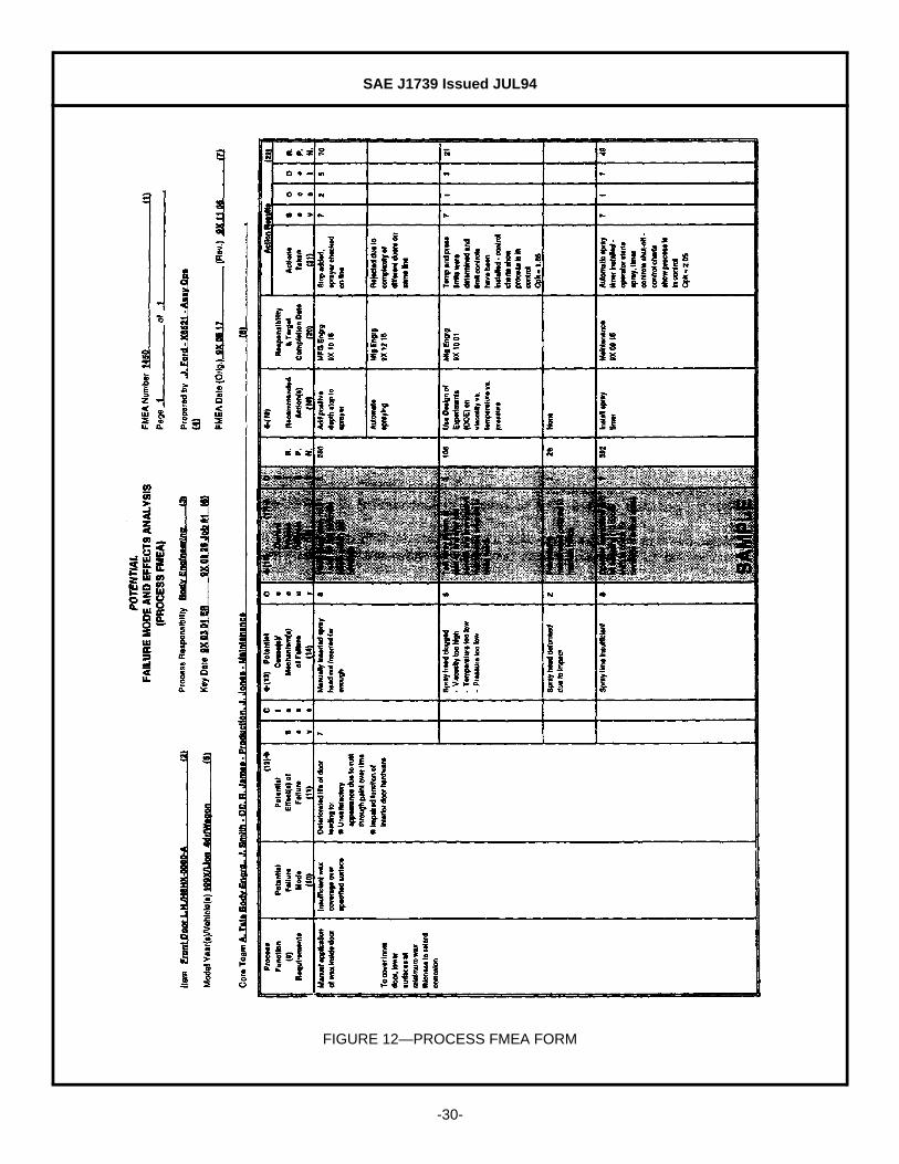
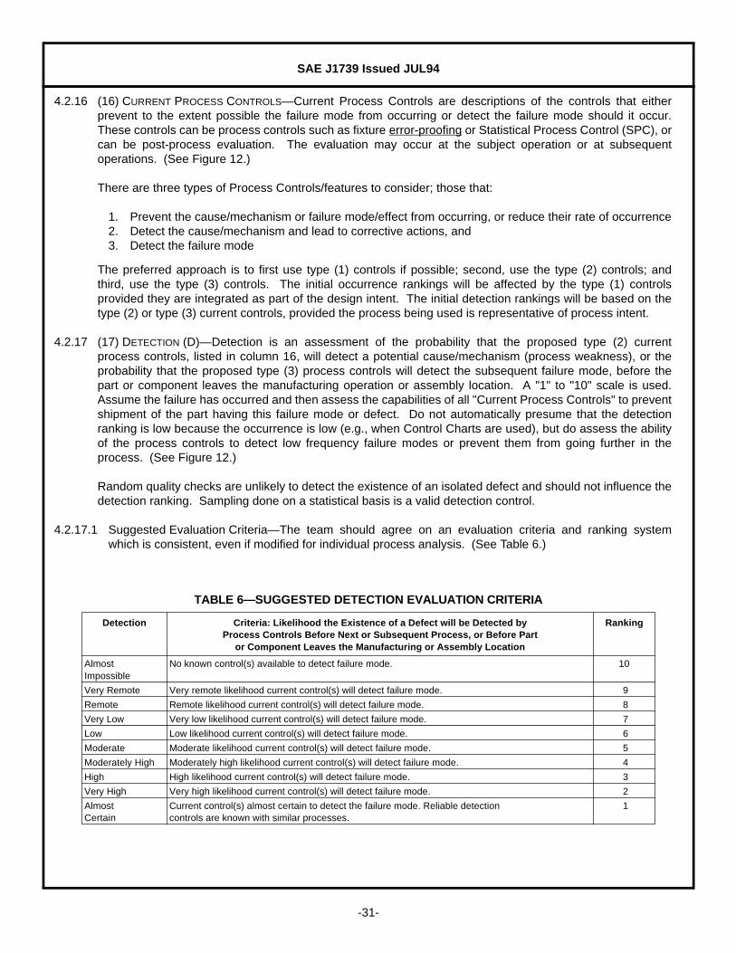
4.2.16 (16) CURRENT PROCESS CONTROLS—Current Process Controls are descriptions of the controls that eitherprevent to the extent possible the failure mode from occurring or detect the failure mode should it occur.These controls can be process controls such as fixture error-proofing or Statistical Process Control (SPC), orcan be post-process evaluation. The evaluation may occur at the subject operation or at subsequentoperations. (See Figure 12.)
There are three types of Process Controls/features to consider; those that:
1. Prevent the cause/mechanism or failure mode/effect from occurring, or reduce their rate of occurrence2. Detect the cause/mechanism and lead to corrective actions, and3. Detect the failure mode
The preferred approach is to first use type (1) controls if possible; second, use the type (2) controls; andthird, use the type (3) controls. The initial occurrence rankings will be affected by the type (1) controlsprovided they are integrated as part of the design intent. The initial detection rankings will be based on thetype (2) or type (3) current controls, provided the process being used is representative of process intent.
4.2.17 (17) DETECTION (D)—Detection is an assessment of the probability that the proposed type (2) currentprocess controls, listed in column 16, will detect a potential cause/mechanism (process weakness), or theprobability that the proposed type (3) process controls will detect the subsequent failure mode, before thepart or component leaves the manufacturing operation or assembly location. A "1" to "10" scale is used.Assume the failure has occurred and then assess the capabilities of all "Current Process Controls" to preventshipment of the part having this failure mode or defect. Do not automatically presume that the detectionranking is low because the occurrence is low (e.g., when Control Charts are used), but do assess the abilityof the process controls to detect low frequency failure modes or prevent them from going further in theprocess. (See Figure 12.)
Random quality checks are unlikely to detect the existence of an isolated defect and should not influence thedetection ranking. Sampling done on a statistical basis is a valid detection control.
4.2.17.1 Suggested Evaluation Criteria—The team should agree on an evaluation criteria and ranking systemwhich is consistent, even if modified for individual process analysis. (See Table 6.)
TABLE 6—SUGGESTED DETECTION EVALUATION CRITERIA
Detection Criteria: Likelihood the Existence of a Defect will be Detected byProcess Controls Before Next or Subsequent Process, or Before Part
or Component Leaves the Manufacturing or Assembly Location
Ranking
AlmostImpossible
No known control(s) available to detect failure mode. 10
Very Remote Very remote likelihood current control(s) will detect failure mode. 9
Remote Remote likelihood current control(s) will detect failure mode. 8
Very Low Very low likelihood current control(s) will detect failure mode. 7
Low Low likelihood current control(s) will detect failure mode. 6
Moderate Moderate likelihood current control(s) will detect failure mode. 5
Moderately High Moderately high likelihood current control(s) will detect failure mode. 4
High High likelihood current control(s) will detect failure mode. 3
Very High Very high likelihood current control(s) will detect failure mode. 2
AlmostCertain
Current control(s) almost certain to detect the failure mode. Reliable detectioncontrols are known with similar processes.
1

SAE J1739 Issued JUL94
-32-
FIGURE 13—PROCESS FMEA FORM

SAE J1739 Issued JUL94
-33-
4.2.18 (18) RISK PRIORITY NUMBER (RPN)—The Risk Priority Number is the product of the Severity (S), Occurrence(O), and Detection (D) rankings. (See Figure 13 and Equation 2.)
(Eq. 2)
This value should be used to rank order the concerns in the process (e.g., in Pareto fashion). The RPN willbe between "1" and "1000". For high RPNs, the team must undertake efforts to reduce this calculated riskthrough corrective action(s). In general practice, regardless of the resultant RPN, special attention should begiven when severity is high.
4.2.19 (19) RECOMMENDED ACTION(S)—When the failure modes have been rank ordered by RPN, corrective actionshould be first directed at the highest ranked concerns and critical items. If for example, the causes are notfully understood, a recommended action might be determined by a statistical designed experiment (DOE).The intent of any recommended action is to reduce the severity, occurrence, and/or detection rankings. If noactions are recommended for a specific cause, then indicate this by entering a "NONE" in this column. (SeeFigure 13.)
In all cases where the effect of an identified potential failure mode could be a hazard to manufacturing/assembly personnel, corrective actions should be taken to prevent the failure mode by eliminating orcontrolling the cause(s), or appropriate operator protection should be specified.
The need for taking specific, positive corrective actions with quantifiable benefits, recommending actions toother activities and following-up all recommendations cannot be overemphasized. A thoroughly thought outand well developed Process FMEA will be of limited value without positive and effective corrective actions. Itis the responsibility of all affected activities to implement effective follow-up programs to address allrecommendations.
Actions such as the following should be considered:
a. To reduce the probability of occurrence, process and/or design revisions are required. An action-oriented study of the process using statistical methods could be implemented with an ongoingfeedback of information to the appropriate operations for continuous improvement and defectprevention.
b. Only a design and/or process revision can bring about a reduction in the severity ranking.c. To increase the probability of detection, process and/or design revisions are required. Generally,
improving detection controls is costly and ineffective for quality improvements. Increasing qualitycontrols inspection frequency is not positive corrective action and should only be utilized as atemporary measure, permanent corrective action is required. In some cases, a design change to aspecific part may be required to assist in the detection. Changes to the current control system may beimplemented to increase this probability. Emphasis must, however, be placed on preventing defects(i.e., reducing the occurrence) rather than detecting them. An example would be the use of StatisticalProcess Control and process improvement rather than random quality checks or associatedinspection.
4.2.20 (20) RESPONSIBILITY (FOR THE RECOMMENDED ACTION)—Enter the Organization and individual responsiblefor the recommended action, and the target completion date. (See Figure 13.)
4.2.21 (21) ACTIONS TAKEN—After an action has been implemented, enter a brief description of the action andeffective date. (See Figure 13.)

SAE J1739 Issued JUL94
-34-
FIGURE 14—PROCESS FMEA FORM

SAE J1739 Issued JUL94
-35-
4.2.22 (22) RESULTING RPN—After corrective actions have been identified, estimate and record the resultingoccurrence, severity, and detection rankings. Calculate and record the resulting RPN. If no actions aretaken, leave the "Resulting RPN" and related ranking columns blank. (See Figure 14.)
All resulting RPNs should be reviewed and if further action is considered necessary, repeat 4.2.19 through4.2.22.
4.2.23 FOLLOW-UP—The process responsible engineer is responsible for assuring that all actions recommendedhave been implemented or adequately addressed. The FMEA is a living document and should always reflectthe latest design level, as well as the latest relevant actions, including those occurring after the start ofproduction.
PREPARED BY THE SAE J1739 TASK FORCE
SAE J1739 Issued JUL94
-36-
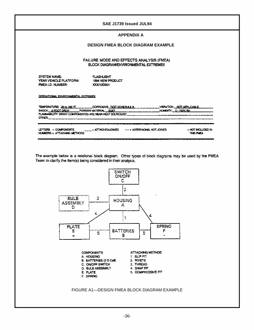
APPENDIX A
DESIGN FMEA BLOCK DIAGRAM EXAMPLE
FIGURE A1—DESIGN FMEA BLOCK DIAGRAM EXAMPLE

SAE J1739 Issued JUL94
-37-
APPENDIX B
DESIGN FMEA EXAMPLE
FIGURE B1—DESIGN FMEA EXAMPLE

SAE J1739 Issued JUL94
-38-
APPENDIX C
PROCESS FMEA FLOW CHART/RISK ASSESSMENT EXAMPLE
TABLE C1—PROCESS FMEA FLOW CHART/RISK ASSESSMENT EXAMPLE
(Application of Wax to Inside of Door)
Process Step Risk Assessment
1. Get wax applicator wand from holder Low risk
2. Open vehicle door Low risk
3. Insert wand and pull trigger for 12 s while making three passes High risk (1)
1. FMEA Required (high risk)
4. Release trigger, wait 3 s Medium risk
5. Remove wand Medium risk
6. Close vehicle door Low risk
7. Replace applicator wand in holder Low risk

SAE J1739 Issued JUL94
-39-
APPENDIX D
PROCESS FMEA EXAMPLE
FIGURE D1—PROCESS FMEA EXAMPLE
SAE J1739 Issued JUL94
-40-
APPENDIX E
GLOSSARY
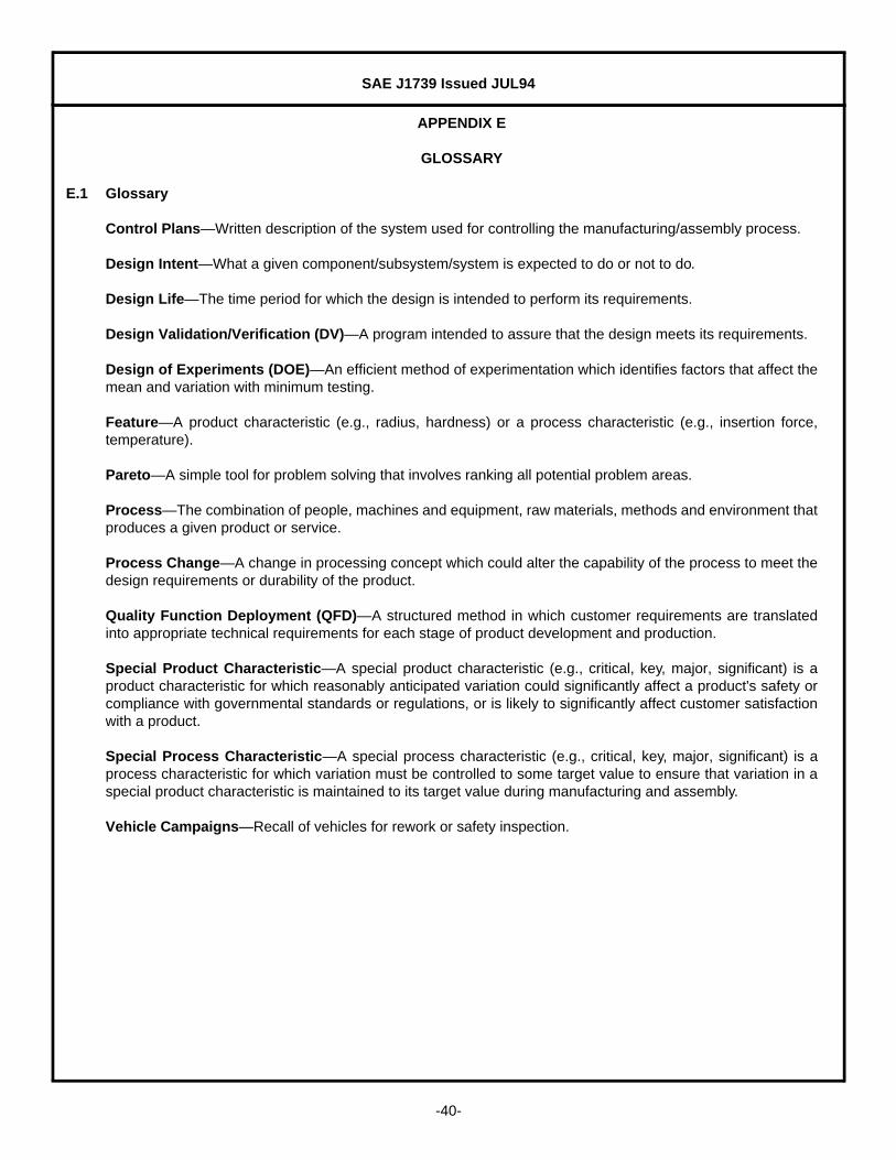
E.1 Glossary
Control Plans—Written description of the system used for controlling the manufacturing/assembly process.
Design Intent—What a given component/subsystem/system is expected to do or not to do.
Design Life—The time period for which the design is intended to perform its requirements.
Design Validation/Verification (DV)—A program intended to assure that the design meets its requirements.
Design of Experiments (DOE)—An efficient method of experimentation which identifies factors that affect themean and variation with minimum testing.
Feature—A product characteristic (e.g., radius, hardness) or a process characteristic (e.g., insertion force,temperature).
Pareto—A simple tool for problem solving that involves ranking all potential problem areas.
Process—The combination of people, machines and equipment, raw materials, methods and environment thatproduces a given product or service.
Process Change—A change in processing concept which could alter the capability of the process to meet thedesign requirements or durability of the product.
Quality Function Deployment (QFD)—A structured method in which customer requirements are translatedinto appropriate technical requirements for each stage of product development and production.
Special Product Characteristic—A special product characteristic (e.g., critical, key, major, significant) is aproduct characteristic for which reasonably anticipated variation could significantly affect a product's safety orcompliance with governmental standards or regulations, or is likely to significantly affect customer satisfactionwith a product.
Special Process Characteristic—A special process characteristic (e.g., critical, key, major, significant) is aprocess characteristic for which variation must be controlled to some target value to ensure that variation in aspecial product characteristic is maintained to its target value during manufacturing and assembly.
Vehicle Campaigns—Recall of vehicles for rework or safety inspection.

SAE J1739 Issued JUL94
-41-
APPENDIX F
STANDARD FORM FOR DESIGN FMEA
FIGURE F1—STANDARD FORM FOR DESIGN FMEA

SAE J1739 Issued JUL94
-42-
APPENDIX G
STANDARD FORM FOR PROCESS FMEA
FIGURE G1—STANDARD FORM FOR PROCESS FMEA
SAE J1739 Issued JUL94
Rationale—Not applicable.
Relationship of SAE Standard to ISO Standard—Not Applicable.
Application—This SAE Recommended Practice was jointly developed by Chrysler, Ford, and General Motorsunder the sponsorship of the United States Council for Automotive Research (USCAR).
This document introduces the topic of potential Failure Mode and Effects Analysis (FMEA) and givesgeneral guidance in the application of the technique. An FMEA can be described as a systemized groupof activities intended to: (a) recognize and evaluate the potential failure for a product/process and itseffects, (b) identify actions which could eliminate or reduce the chance of the potential failure occurring,and (c) document the process. It is complementary to the design process of defining positively what adesign must do to satisfy the customer.
Reference Section—There are no referenced publications specified herein.
Developed by the SAE J1739 Task Force


![UNMANNED SURFACE VEHICLE [USV] - Maritime Robotics · unmanned surface vehicle [usv] cost efficient and risk-reducing maritime data acquisition ottertm](https://img.pdfslide.us/doc/110x75/5ac0249d7f8b9a5a4e8ba2dd/unmanned-surface-vehicle-usv-maritime-robotics-surface-vehicle-usv-cost-efficient.jpg)


![Energy Design of an Autonomous Surface Vehicle (ASV) · An Autonomous Surface Vehicle (ASV) is a vehicle that operates at the surface of the water without a crew [2]. It can be equipped](https://img.pdfslide.us/doc/110x75/5fc0082e0b4e303441157e9e/energy-design-of-an-autonomous-surface-vehicle-asv-an-autonomous-surface-vehicle.jpg)